JP7413089B2 - Image forming device - Google Patents
Image forming device Download PDFInfo
- Publication number
- JP7413089B2 JP7413089B2 JP2020038853A JP2020038853A JP7413089B2 JP 7413089 B2 JP7413089 B2 JP 7413089B2 JP 2020038853 A JP2020038853 A JP 2020038853A JP 2020038853 A JP2020038853 A JP 2020038853A JP 7413089 B2 JP7413089 B2 JP 7413089B2
- Authority
- JP
- Japan
- Prior art keywords
- connector
- image forming
- tray
- main body
- photoreceptor unit
- Prior art date
- Legal status (The legal status is an assumption and is not a legal conclusion. Google has not performed a legal analysis and makes no representation as to the accuracy of the status listed.)
- Active
Links
- 108091008695 photoreceptors Proteins 0.000 claims description 41
- 238000000034 method Methods 0.000 claims description 11
- 230000008569 process Effects 0.000 claims description 11
- 238000003780 insertion Methods 0.000 description 40
- 230000037431 insertion Effects 0.000 description 40
- 238000000926 separation method Methods 0.000 description 30
- 230000015654 memory Effects 0.000 description 22
- 230000033001 locomotion Effects 0.000 description 16
- 238000001179 sorption measurement Methods 0.000 description 9
- 238000012546 transfer Methods 0.000 description 9
- 238000010586 diagram Methods 0.000 description 7
- 238000010438 heat treatment Methods 0.000 description 5
- 238000011144 upstream manufacturing Methods 0.000 description 4
- 230000008878 coupling Effects 0.000 description 3
- 238000010168 coupling process Methods 0.000 description 3
- 238000005859 coupling reaction Methods 0.000 description 3
- 239000000463 material Substances 0.000 description 3
- 230000004048 modification Effects 0.000 description 3
- 238000012986 modification Methods 0.000 description 3
- 239000000123 paper Substances 0.000 description 3
- 238000013459 approach Methods 0.000 description 2
- 230000015572 biosynthetic process Effects 0.000 description 2
- 230000000052 comparative effect Effects 0.000 description 2
- 239000000428 dust Substances 0.000 description 2
- 230000005674 electromagnetic induction Effects 0.000 description 2
- 229910052736 halogen Inorganic materials 0.000 description 2
- 150000002367 halogens Chemical class 0.000 description 2
- 239000011111 cardboard Substances 0.000 description 1
- 239000003086 colorant Substances 0.000 description 1
- 238000007599 discharging Methods 0.000 description 1
- 230000000694 effects Effects 0.000 description 1
- 238000005516 engineering process Methods 0.000 description 1
- 239000004744 fabric Substances 0.000 description 1
- 230000006870 function Effects 0.000 description 1
- 230000005484 gravity Effects 0.000 description 1
- 238000009434 installation Methods 0.000 description 1
- 238000004519 manufacturing process Methods 0.000 description 1
- 230000007246 mechanism Effects 0.000 description 1
- 239000011087 paperboard Substances 0.000 description 1
- 239000002985 plastic film Substances 0.000 description 1
- 229920006255 plastic film Polymers 0.000 description 1
- 239000011347 resin Substances 0.000 description 1
- 229920005989 resin Polymers 0.000 description 1
- 239000000758 substrate Substances 0.000 description 1
- 238000004381 surface treatment Methods 0.000 description 1
Images


Classifications
-
- G—PHYSICS
- G03—PHOTOGRAPHY; CINEMATOGRAPHY; ANALOGOUS TECHNIQUES USING WAVES OTHER THAN OPTICAL WAVES; ELECTROGRAPHY; HOLOGRAPHY
- G03G—ELECTROGRAPHY; ELECTROPHOTOGRAPHY; MAGNETOGRAPHY
- G03G21/00—Arrangements not provided for by groups G03G13/00 - G03G19/00, e.g. cleaning, elimination of residual charge
- G03G21/16—Mechanical means for facilitating the maintenance of the apparatus, e.g. modular arrangements
- G03G21/18—Mechanical means for facilitating the maintenance of the apparatus, e.g. modular arrangements using a processing cartridge, whereby the process cartridge comprises at least two image processing means in a single unit
- G03G21/1839—Means for handling the process cartridge in the apparatus body
- G03G21/1867—Means for handling the process cartridge in the apparatus body for electrically connecting the process cartridge to the apparatus, electrical connectors, power supply
-
- G—PHYSICS
- G03—PHOTOGRAPHY; CINEMATOGRAPHY; ANALOGOUS TECHNIQUES USING WAVES OTHER THAN OPTICAL WAVES; ELECTROGRAPHY; HOLOGRAPHY
- G03G—ELECTROGRAPHY; ELECTROPHOTOGRAPHY; MAGNETOGRAPHY
- G03G21/00—Arrangements not provided for by groups G03G13/00 - G03G19/00, e.g. cleaning, elimination of residual charge
- G03G21/16—Mechanical means for facilitating the maintenance of the apparatus, e.g. modular arrangements
- G03G21/18—Mechanical means for facilitating the maintenance of the apparatus, e.g. modular arrangements using a processing cartridge, whereby the process cartridge comprises at least two image processing means in a single unit
- G03G21/1803—Arrangements or disposition of the complete process cartridge or parts thereof
- G03G21/1817—Arrangements or disposition of the complete process cartridge or parts thereof having a submodular arrangement
- G03G21/1821—Arrangements or disposition of the complete process cartridge or parts thereof having a submodular arrangement means for connecting the different parts of the process cartridge, e.g. attachment, positioning of parts with each other, pressure/distance regulation
-
- G—PHYSICS
- G03—PHOTOGRAPHY; CINEMATOGRAPHY; ANALOGOUS TECHNIQUES USING WAVES OTHER THAN OPTICAL WAVES; ELECTROGRAPHY; HOLOGRAPHY
- G03G—ELECTROGRAPHY; ELECTROPHOTOGRAPHY; MAGNETOGRAPHY
- G03G21/00—Arrangements not provided for by groups G03G13/00 - G03G19/00, e.g. cleaning, elimination of residual charge
- G03G21/16—Mechanical means for facilitating the maintenance of the apparatus, e.g. modular arrangements
- G03G21/1642—Mechanical means for facilitating the maintenance of the apparatus, e.g. modular arrangements for connecting the different parts of the apparatus
- G03G21/1652—Electrical connection means
-
- G—PHYSICS
- G03—PHOTOGRAPHY; CINEMATOGRAPHY; ANALOGOUS TECHNIQUES USING WAVES OTHER THAN OPTICAL WAVES; ELECTROGRAPHY; HOLOGRAPHY
- G03G—ELECTROGRAPHY; ELECTROPHOTOGRAPHY; MAGNETOGRAPHY
- G03G15/00—Apparatus for electrographic processes using a charge pattern
- G03G15/06—Apparatus for electrographic processes using a charge pattern for developing
- G03G15/08—Apparatus for electrographic processes using a charge pattern for developing using a solid developer, e.g. powder developer
- G03G15/0822—Arrangements for preparing, mixing, supplying or dispensing developer
- G03G15/0863—Arrangements for preparing, mixing, supplying or dispensing developer provided with identifying means or means for storing process- or use parameters, e.g. an electronic memory
-
- G—PHYSICS
- G03—PHOTOGRAPHY; CINEMATOGRAPHY; ANALOGOUS TECHNIQUES USING WAVES OTHER THAN OPTICAL WAVES; ELECTROGRAPHY; HOLOGRAPHY
- G03G—ELECTROGRAPHY; ELECTROPHOTOGRAPHY; MAGNETOGRAPHY
- G03G21/00—Arrangements not provided for by groups G03G13/00 - G03G19/00, e.g. cleaning, elimination of residual charge
- G03G21/16—Mechanical means for facilitating the maintenance of the apparatus, e.g. modular arrangements
- G03G21/1642—Mechanical means for facilitating the maintenance of the apparatus, e.g. modular arrangements for connecting the different parts of the apparatus
- G03G21/1647—Mechanical connection means
-
- G—PHYSICS
- G03—PHOTOGRAPHY; CINEMATOGRAPHY; ANALOGOUS TECHNIQUES USING WAVES OTHER THAN OPTICAL WAVES; ELECTROGRAPHY; HOLOGRAPHY
- G03G—ELECTROGRAPHY; ELECTROPHOTOGRAPHY; MAGNETOGRAPHY
- G03G21/00—Arrangements not provided for by groups G03G13/00 - G03G19/00, e.g. cleaning, elimination of residual charge
- G03G21/16—Mechanical means for facilitating the maintenance of the apparatus, e.g. modular arrangements
- G03G21/1661—Mechanical means for facilitating the maintenance of the apparatus, e.g. modular arrangements means for handling parts of the apparatus in the apparatus
- G03G21/1671—Mechanical means for facilitating the maintenance of the apparatus, e.g. modular arrangements means for handling parts of the apparatus in the apparatus for the photosensitive element
-
- G—PHYSICS
- G03—PHOTOGRAPHY; CINEMATOGRAPHY; ANALOGOUS TECHNIQUES USING WAVES OTHER THAN OPTICAL WAVES; ELECTROGRAPHY; HOLOGRAPHY
- G03G—ELECTROGRAPHY; ELECTROPHOTOGRAPHY; MAGNETOGRAPHY
- G03G21/00—Arrangements not provided for by groups G03G13/00 - G03G19/00, e.g. cleaning, elimination of residual charge
- G03G21/16—Mechanical means for facilitating the maintenance of the apparatus, e.g. modular arrangements
- G03G21/1661—Mechanical means for facilitating the maintenance of the apparatus, e.g. modular arrangements means for handling parts of the apparatus in the apparatus
- G03G21/1676—Mechanical means for facilitating the maintenance of the apparatus, e.g. modular arrangements means for handling parts of the apparatus in the apparatus for the developer unit
-
- G—PHYSICS
- G03—PHOTOGRAPHY; CINEMATOGRAPHY; ANALOGOUS TECHNIQUES USING WAVES OTHER THAN OPTICAL WAVES; ELECTROGRAPHY; HOLOGRAPHY
- G03G—ELECTROGRAPHY; ELECTROPHOTOGRAPHY; MAGNETOGRAPHY
- G03G21/00—Arrangements not provided for by groups G03G13/00 - G03G19/00, e.g. cleaning, elimination of residual charge
- G03G21/16—Mechanical means for facilitating the maintenance of the apparatus, e.g. modular arrangements
- G03G21/18—Mechanical means for facilitating the maintenance of the apparatus, e.g. modular arrangements using a processing cartridge, whereby the process cartridge comprises at least two image processing means in a single unit
- G03G21/1803—Arrangements or disposition of the complete process cartridge or parts thereof
- G03G21/1814—Details of parts of process cartridge, e.g. for charging, transfer, cleaning, developing
-
- G—PHYSICS
- G03—PHOTOGRAPHY; CINEMATOGRAPHY; ANALOGOUS TECHNIQUES USING WAVES OTHER THAN OPTICAL WAVES; ELECTROGRAPHY; HOLOGRAPHY
- G03G—ELECTROGRAPHY; ELECTROPHOTOGRAPHY; MAGNETOGRAPHY
- G03G21/00—Arrangements not provided for by groups G03G13/00 - G03G19/00, e.g. cleaning, elimination of residual charge
- G03G21/16—Mechanical means for facilitating the maintenance of the apparatus, e.g. modular arrangements
- G03G21/18—Mechanical means for facilitating the maintenance of the apparatus, e.g. modular arrangements using a processing cartridge, whereby the process cartridge comprises at least two image processing means in a single unit
- G03G21/1839—Means for handling the process cartridge in the apparatus body
- G03G21/1867—Means for handling the process cartridge in the apparatus body for electrically connecting the process cartridge to the apparatus, electrical connectors, power supply
- G03G21/1871—Means for handling the process cartridge in the apparatus body for electrically connecting the process cartridge to the apparatus, electrical connectors, power supply associated with a positioning function
-
- G—PHYSICS
- G03—PHOTOGRAPHY; CINEMATOGRAPHY; ANALOGOUS TECHNIQUES USING WAVES OTHER THAN OPTICAL WAVES; ELECTROGRAPHY; HOLOGRAPHY
- G03G—ELECTROGRAPHY; ELECTROPHOTOGRAPHY; MAGNETOGRAPHY
- G03G2221/00—Processes not provided for by group G03G2215/00, e.g. cleaning or residual charge elimination
- G03G2221/16—Mechanical means for facilitating the maintenance of the apparatus, e.g. modular arrangements and complete machine concepts
- G03G2221/1651—Mechanical means for facilitating the maintenance of the apparatus, e.g. modular arrangements and complete machine concepts for connecting the different parts
- G03G2221/166—Electrical connectors
-
- G—PHYSICS
- G03—PHOTOGRAPHY; CINEMATOGRAPHY; ANALOGOUS TECHNIQUES USING WAVES OTHER THAN OPTICAL WAVES; ELECTROGRAPHY; HOLOGRAPHY
- G03G—ELECTROGRAPHY; ELECTROPHOTOGRAPHY; MAGNETOGRAPHY
- G03G2221/00—Processes not provided for by group G03G2215/00, e.g. cleaning or residual charge elimination
- G03G2221/16—Mechanical means for facilitating the maintenance of the apparatus, e.g. modular arrangements and complete machine concepts
- G03G2221/1678—Frame structures
- G03G2221/1684—Frame structures using extractable subframes, e.g. on rails or hinges
-
- G—PHYSICS
- G03—PHOTOGRAPHY; CINEMATOGRAPHY; ANALOGOUS TECHNIQUES USING WAVES OTHER THAN OPTICAL WAVES; ELECTROGRAPHY; HOLOGRAPHY
- G03G—ELECTROGRAPHY; ELECTROPHOTOGRAPHY; MAGNETOGRAPHY
- G03G2221/00—Processes not provided for by group G03G2215/00, e.g. cleaning or residual charge elimination
- G03G2221/16—Mechanical means for facilitating the maintenance of the apparatus, e.g. modular arrangements and complete machine concepts
- G03G2221/18—Cartridge systems
- G03G2221/183—Process cartridge
- G03G2221/1853—Process cartridge having a submodular arrangement
- G03G2221/1869—Cartridge holders, e.g. intermediate frames for placing cartridge parts therein
Description
本発明は、記録媒体に画像を形成する画像形成装置に関する。 The present invention relates to an image forming apparatus that forms an image on a recording medium.
レーザービームプリンタやLEDプリンタ等の画像形成装置において、装置本体から引き出し可能なトレイを設け、画像形成プロセスを実行するための複数の部品をトレイに対して着脱可能なカートリッジとして構成したものがある。この構成では、ユーザがトレイを引き出すことで、カートリッジを容易に交換することができる。 2. Description of the Related Art Some image forming apparatuses, such as laser beam printers and LED printers, are provided with a tray that can be pulled out from the main body of the apparatus, and a plurality of parts for carrying out an image forming process are configured as cartridges that are removably attached to the tray. With this configuration, the user can easily replace the cartridge by pulling out the tray.
特許文献1には、トレイ状のドラムユニットに対して現像カートリッジを着脱可能であり、現像カートリッジを収容した状態でドラムユニットを装置本体に装着する構成の画像形成装置が記載されている。この現像カートリッジには、現像カートリッジに関する様々な情報を記憶するための記憶媒体が取り付けられており、現像カートリッジがドラムユニットに装着された場合にドラムユニットの後部に設けられた中継基板と電気的に接続される。そして、ドラムユニットを装置本体に挿入した際に、中継基板と電気的に接続されたドラムユニット側の接点部材が装置本体側の接点部材と接触することで、装置本体の制御部が現像カートリッジの記憶媒体から情報を取得可能な状態となる。
上記文献に記載の構成では、ドラムユニットを転写ベルトに沿って略水平に移動させた後、水平方向に対して下方に傾斜した方向(第4方向)に移動させることでドラムユニット及び装置本体の接点部材同士が接触する。しかしながら、この構成では、ドラムユニットの挿入を案内するガイドレール等によって移動方向を規制されずに、ドラムユニットが重力に付勢ながら斜め下方に移動している状態で接点部材同士の接続が行われることになり、接続不良が生じる可能性がある。 In the configuration described in the above-mentioned document, the drum unit is moved approximately horizontally along the transfer belt, and then moved in a direction (fourth direction) inclined downward with respect to the horizontal direction. come into contact with each other. However, with this configuration, the contact members are connected to each other while the drum unit is moving diagonally downward while being biased by gravity, without the direction of movement being restricted by a guide rail or the like that guides the insertion of the drum unit. This may result in poor connection.
そこで、本発明は、接点部材同士の接続不良が発生し難い画像形成装置を提供することを目的とする。 SUMMARY OF THE INVENTION Therefore, an object of the present invention is to provide an image forming apparatus in which poor connection between contact members is less likely to occur.
本発明の一態様は、制御部を有する装置本体と、前記装置本体に装着された感光体ユニットであって、回転軸線を中心に回転可能な感光体を有し、前記装置本体に対して前記回転軸線の方向と交差する方向に移動する感光体ユニットと、前記装置本体に設けられ、前記装置本体に対して前記感光体ユニットが移動させられる時に前記感光体ユニットをガイドするガイド手段と、前記感光体ユニットに設けられた装着部に着脱可能に構成される現像カートリッジであって、現像剤を収容する筐体と、前記筐体に収容された前記現像剤を用いて前記感光体上の静電潜像を現像する現像ローラと、現像カートリッジに関する情報を記憶する記憶媒体と、を有する現像カートリッジと、前記感光体ユニットに設けられた第1コネクタであって、前記現像カートリッジが前記感光体ユニットに装着された状態で前記記憶媒体と電気的に接続される第1接点端子を有し、前記感光体ユニットに対して上下方向に移動可能な第1コネクタと、前記装置本体に設けられた第2コネクタであって、前記制御部と電気的に接続された第2接点端子を有し、前記第1接点端子と前記第2接点端子が接触するように前記第1コネクタと係合可能な第2コネクタと、を備えた画像形成装置であって、前記感光体ユニットは、前記ガイド手段によってガイドされながら着脱位置から画像形成位置に移動するように構成され、前記着脱位置は、前記装着部に対する前記現像カートリッジの着脱が可能となる位置であり、前記画像形成位置は、前記第1コネクタの前記第1接点端子と前記第2コネクタの前記第2接点端子が接触し且つ前記画像形成装置が画像形成動作を実行可能となる位置であって、前記着脱位置よりも下方の位置であり、前記第1コネクタは、前記回転軸線の方向に見た時に、水平方向において前記着脱位置から前記画像形成位置に向かう方向における前記感光体ユニットの端部に設けられており、前記感光体ユニットは、前記着脱位置から前記画像形成位置に移動する過程で前記感光体ユニットの前記端部の移動方向が前記水平方向に対して下向きに傾くように、前記ガイド手段によってガイドされ、前記第1コネクタ及び前記第2コネクタは、前記感光体ユニットが前記着脱位置から前記画像形成位置に移動させられている間に、前記感光体ユニットの前記端部の前記移動方向の前記水平方向に対する下向きの角度が最大角度となる前に、互いに係合するように構成されている、ことを特徴とする画像形成装置である。 One aspect of the present invention includes an apparatus main body having a control section, and a photoreceptor unit mounted on the apparatus main body , the photoreceptor unit being rotatable around a rotation axis, and with respect to the apparatus main body. a photoreceptor unit that moves in a direction intersecting the direction of the rotation axis ; a guide means that is provided in the apparatus main body and guides the photoreceptor unit when the photoreceptor unit is moved relative to the apparatus main body; The developer cartridge is configured to be removably attached to a mounting portion provided on the photoconductor unit, and includes a casing for accommodating a developer, and a developer cartridge that uses the developer accommodated in the casing to develop an image on the photoconductor. a developer cartridge having a developer roller that develops an electrostatic latent image; a storage medium that stores information regarding the developer cartridge; and a first connector provided on the photoconductor unit, wherein the developer cartridge is connected to the photoconductor unit. a first connector that has a first contact terminal that is electrically connected to the storage medium when attached to the unit and is movable in the vertical direction with respect to the photoreceptor unit; and a first connector that is provided on the device main body. a second connector, the second connector having a second contact terminal electrically connected to the control unit, and engageable with the first connector so that the first contact terminal and the second contact terminal are in contact with each other; a second connector, wherein the photoreceptor unit is configured to move from an attachment/detachment position to an image forming position while being guided by the guide means, and the attachment/detachment position is located at the mounting portion. The image forming position is a position where the first contact terminal of the first connector and the second contact terminal of the second connector are in contact with each other and the image forming apparatus is The position is a position where an image forming operation can be performed, and is a position below the attachment/detachment position, and the first connector is configured to perform image forming from the attachment/detachment position in the horizontal direction when viewed in the direction of the rotation axis. The photoreceptor unit is provided at an end of the photoreceptor unit in a direction toward the position, and the direction of movement of the end of the photoreceptor unit is in the process of moving from the attachment/detachment position to the image forming position . The first connector and the second connector are guided by the guide means so as to be tilted downward with respect to the horizontal direction, and the first connector and the second connector , wherein the end portions of the photoreceptor units are configured to engage with each other before the downward angle of the moving direction with respect to the horizontal direction reaches a maximum angle. .
本発明によれば、接点部材同士の接続不良が発生し難い画像形成装置を提供することができる。 According to the present invention, it is possible to provide an image forming apparatus in which poor connection between contact members is unlikely to occur.
以下、本発明を実施するための例示的な形態について、図面を参照しながら説明する。以下の説明では、画像形成装置に関して、ユーザがアクセスする側として想定される方向(前ドアを有する場合は前ドアが設けられた側)を正面側、正面側と反対側を背面側と称する。また、画像形成装置を正面から見て左側を画像形成装置の左側、右側を画像形成装置の右側と称する。 Hereinafter, exemplary embodiments for carrying out the present invention will be described with reference to the drawings. In the following description, regarding the image forming apparatus, the direction assumed to be the side to which the user accesses (if the image forming apparatus has a front door, the side where the front door is provided) will be referred to as the front side, and the side opposite to the front side will be referred to as the back side. Further, when the image forming apparatus is viewed from the front, the left side is called the left side of the image forming apparatus, and the right side is called the right side of the image forming apparatus.
また、感光ドラムの軸線が延びる方向(下記の実施例では画像形成装置の右側から左側に向かう方向)をX方向とし、鉛直方向をZ方向とし、X方向及びZ方向に交差する方向(下記の実施例では画像形成装置の背面方向)をY方向とする。X方向、Y方向、Z方向は、好ましくは互いに直交する直交座標系である。つまり、X方向及びY方向は好ましくはいずれも水平方向である。また、以下の説明において、画像形成装置の構成要素の形状や構成要素間の位置関係について言及するときは、特に断らない限り、各構成要素が画像形成装置に組付けられた状態における位置や姿勢を前提とするものとする。 In addition, the direction in which the axis of the photosensitive drum extends (in the example below, the direction from the right side to the left side of the image forming apparatus) is defined as the X direction, the vertical direction is defined as the Z direction, and the direction intersecting the X and Z directions (as described below) In the embodiment, the direction (back direction) of the image forming apparatus is defined as the Y direction. The X direction, Y direction, and Z direction are preferably mutually orthogonal coordinate systems. That is, the X direction and the Y direction are preferably both horizontal directions. In addition, in the following description, when referring to the shape of the components of the image forming apparatus or the positional relationship between the components, unless otherwise specified, the position or orientation of each component when assembled into the image forming apparatus is referred to. It is assumed that
(1)画像形成装置の概略構成
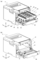
実施例1に係る画像形成装置1の構成について説明する。図1は、本実施例に係る画像形成装置1の断面構成を表す概略図である。図1に示すように、画像形成装置1は、装置本体2と、カートリッジトレイ3と、カートリッジトレイに着脱可能に保持される現像カートリッジ8k、8c、8m、8yを有する。画像形成装置1は、電子写真プロセスによって記録媒体に画像を形成する4色フルカラーレーザプリンタであり、記録媒体Sにカラー画像を形成する。記録媒体Sとしては、普通紙及び厚紙等の紙、プラスチックフィルム、布、コート紙のような表面処理が施されたシート材、封筒やインデックス紙等の特殊形状のシート材等、サイズ及び材質の異なる多様なシートを使用可能である。
(1) Schematic configuration of image forming apparatus The configuration of the
カートリッジトレイ3は、トレイ枠体30と、トレイ枠体30に回転可能に支持される複数の感光ドラム4k、4c、4m、4yと、現像カートリッジ8k~8yを収容するカートリッジ収容部89k、89c、89m、89y(図4参照)と、を有する。各感光ドラム4k~4yは、ドラム状に構成された電子写真感光体(像担持体)である。カートリッジトレイ3は、少なくとも1つの感光体を備えた感光体ユニットの例である。各現像カートリッジ8k~8yは、現像剤を収容する筐体7k、7c、7m、7yと、現像剤を用いて現像プロセスを行うための現像ローラ6k、6c、6m、6yと、を有する。また、カートリッジトレイ3には、感光ドラム4k~4yに対応する帯電ローラ5k、5c、5m、5yが設けられている。
The
装置本体2の正面側には前ドア40が開閉可能に設けられており、後述するように前ドア40を開放することでカートリッジトレイ3を装置本体2から引き出し、カートリッジトレイ3及び現像カートリッジ8k~8yの交換を行うことができる。なお、装置本体2とは、画像形成装置1からカートリッジトレイ3及び現像カートリッジ8k~8yを除いた部分を指し、例えば画像形成装置1の枠体を含んでいる。
A
装置本体2内における現像カートリッジ8k~8y及びカートリッジトレイ3の上方には、露光手段としてのレーザスキャナユニットLBが設けられている。また、装置本体2内における現像カートリッジ8k~8y及びカートリッジトレイ3の下方には、搬送手段としてのベルトユニット11が設けられている。このベルトユニット11は、駆動ローラ13及びテンションローラ14に、可撓性を有する静電吸着ベルト12を張架したものである。静電吸着ベルト12は、記録媒体Sを搬送するベルト部材の一例である。本実施例の静電吸着ベルト12は、駆動ローラ13とテンションローラ14との間で略水平方向に掛け渡されている。
A laser scanner unit LB as an exposure means is provided above the
静電吸着ベルト12の内側には、感光ドラム4k~4yに対向させて転写ローラ16k、16c、16m、16yを設けている。この感光ドラム4k~4yと転写ローラ16k、16c、16m、16yが対向する箇所(感光ドラム4k~4yと静電吸着ベルト12との間のニップ部)は、転写プロセスが行われる転写部である。
ベルトユニット11の下方には、給送ユニット18を設けている。この給送ユニット18は、記録媒体Sが積載されて収納される給送トレイ19と、給送ローラ20と、を有し、記録媒体Sを1枚ずつ給送する。Y方向でベルトユニット11の側方には、定着プロセスを行う定着ユニット21が設けられている。定着ユニット21の上方で装置本体2の上部には、記録媒体Sを装置本体2外に排出する排出ユニット22が設けられている。
A
また、図1に模式的に示すように、装置本体2には、画像形成装置1を制御する制御部として、制御基板2Cが搭載されている。制御基板2Cは、画像形成装置1の制御プログラムを実行するCPUと、制御プログラム及び画像形成装置1の制御に必要なデータ等を格納するメモリと、を有する。CPUは、メモリから制御プログラムを読み出して実行することで、例えば感光ドラム4k~4y等を駆動するためのモータや帯電ローラ5k~5y等にバイアス電圧を印加するための高圧基板を制御して画像形成動作を実行する。
Further, as schematically shown in FIG. 1, a
(2)画像形成動作
図1及び図2を用いて画像形成動作について説明する。フルカラー画像を形成するための動作は次の通りである。現像カートリッジ8k~8yがカートリッジトレイ3に装着された状態でカートリッジトレイ3が装置本体2に挿入された後、前ドア40が閉じられることで、カートリッジトレイ3及び現像カートリッジ8k~8yの画像形成装置1への装着が完了する。
(2) Image forming operation Image forming operation will be explained using FIGS. 1 and 2. The operations for forming a full color image are as follows. After the
前ドア40が閉じられると、画像形成装置1に設けられた不図示のドラム駆動カップリングが、カートリッジトレイ3に設けられた感光ドラム4に接続されているドラムカップリング54と係合する。画像形成装置1が画像形成の実行指示を受け取ると、装置本体2の不図示の駆動出力モータ及びギアを介して、ドラムカップリング54が回転駆動され、これによって感光ドラム4が所定の速度で回転駆動される。静電吸着ベルト12も感光ドラム4の速度に対応した速度で回転駆動される。このとき、レーザスキャナユニットLBも駆動され、発光する。レーザスキャナユニットLBの発光に同期して、帯電ローラ5k~5yによって感光ドラム4表面が所定の極性・電位に一様に帯電される。レーザスキャナユニットLBは各感光ドラム4の表面を各色の画像信号に応じてレーザー光Lで走査露光する。これにより、感光ドラム4の表面(感光体上)に対応色の画像信号に応じた静電潜像が形成される。
When the
この静電潜像は、所定の速度で回転駆動される現像ローラ6k~6yにより現像される。このようなプロセスを経て、第1の感光ドラム4yにはフルカラー画像のイエロー成分に対応するイエロー色のトナー像が形成される。同様に、第2~第4の感光ドラム4m、4c、4kにはフルカラー画像のマゼンタ色、シアン色、ブラック色に対応するトナー像が形成される。
This electrostatic latent image is developed by developing
一方、給送トレイ19からは所定の制御タイミングで記録媒体Sが1枚ずつ分離されて給送される。記録媒体Sが第1~第4の感光ドラム4y、4m、4c、4kを順に通過する間に、記録媒体Sにはイエロー色、マゼンタ色、シアン色、ブラック色のトナー像が重畳転写される。このようにして、記録媒体S上に4色フルカラーの未定着トナー像が形成される。
On the other hand, the recording media S are separated and fed one by one from the feeding
トナー像を転写された記録媒体Sは、定着ユニット21で定着処理を受ける。定着ユニット21は、記録媒体Sを挟持して搬送するローラ対と、記録媒体S上のトナー像を加熱するための加熱手段(例えば、ハロゲンランプや電磁誘導加熱ユニット)を有し、未定着トナー像に熱及び圧力を加える。これによりトナーが溶融・混色し、その後固着することで、記録媒体Sに定着した定着画像が得られる。定着ユニット21を通過した記録媒体Sは、排出ユニット22によって装置本体2の上面に設けられた排出トレイ23へ排出される。
The recording medium S onto which the toner image has been transferred undergoes a fixing process in the fixing unit 21. The fixing unit 21 includes a pair of rollers that nip and convey the recording medium S, and a heating means (for example, a halogen lamp or an electromagnetic induction heating unit) for heating the toner image on the recording medium S, and has a heating unit (for example, a halogen lamp or an electromagnetic induction heating unit) that fixes the unfixed toner. Apply heat and pressure to the image. As a result, the toners are melted and mixed, and then fixed, so that a fixed image fixed on the recording medium S is obtained. The recording medium S that has passed through the fixing unit 21 is discharged by a
(3)カートリッジトレイの挿抜動作
次に、図2を用いて装置本体2に対するカートリッジトレイ3の挿抜動作について説明する。図2(a)は、前ドア40を開いて装置本体2からカートリッジトレイ3を引出位置まで引き出した状態を表している。ただし、引出位置とは、現像カートリッジ8k~8yの着脱を容易に行うことができる程度に現像カートリッジ8k~8yが装置本体2から露出する位置を指す。本実施例では、後述のストッパーによりカートリッジトレイ3の引き出しが規制される位置を引出位置とする。
(3) Insertion and removal operation of cartridge tray Next, the insertion and removal operation of
図2(b)は、装置本体2からカートリッジトレイ3を取り外した状態を表している。画像形成装置1内部で記録媒体Sの搬送不良(ジャム)が生じた場合、図2(b)に示すようにカートリッジトレイ3を装置本体2から取り外すことで記録媒体Sの搬送経路の一部が開放され、詰まった記録媒体Sを容易に除去することができる。
FIG. 2(b) shows a state in which the
次に図3、図4、図5(a~c)を用いてカートリッジトレイ3の挿抜を案内するガイド構成の説明をする。図3は、現像カートリッジ8k~8yを装着したカートリッジ装着状態のカートリッジトレイ3を挿入方向D1の下流側から見た斜視図である。図4は、現像カートリッジ8k~8yを装着していないカートリッジ未装着状態のカートリッジトレイ3を挿入方向D1の上流側から見た斜視図である。ただし、挿入方向D1(本実施例の第1方向)とは、カートリッジトレイ3を引出位置から装置本体2内に向けて挿入するときのカートリッジトレイ3の移動方向である。本実施例における挿入方向D1は、X方向に見て実質的に水平方向である。
Next, the guide structure for guiding the insertion and removal of the
カートリッジトレイ3のトレイ枠体30のX方向における両側面には、図3、図4に示すように、各側面からトレイ枠体30の外側に突出したトレイガイド49L、49Rが設けられている。また、Y方向におけるトレイガイド49L、49Rの背面側部分には、トレイ枠体30に対して回転可能に支持されたガイドコロ50L、50Rが設けられている。
As shown in FIGS. 3 and 4, tray guides 49L and 49R are provided on both side surfaces of the
図5(a~c)を用いて詳細なカートリッジトレイ3のガイド構成を説明する。ただし、X方向で一方側のガイド構成と他方側のガイド構成は実質的に対称であるため、図5に関しては、X方向の一方側と他方側を区別せずに説明し、説明された構成はX方向の両側に設けられているものとする。例えば、トレイガイド49L、49Rを区別せずに「トレイガイド49」とし、X方向の一方側と他方側のガイドコロを区別せずに「ガイドコロ50」とする。
The guide configuration of the
図5(a)に示すように、トレイガイド49のZ方向下側の下面49aは、Y方向に延びた面である。また、ガイドコロ50の最下部は、トレイガイド49よりもZ方向で下方に突出している。また、Y方向におけるトレイガイド49の正面側の端部には、トレイガイド傾斜面49bが設けられている。トレイガイド傾斜面49bは、トレイガイド49の正面側の終端に近づくにつれてZ方向上側に向かうように(つまり、挿入方向D1に向かってZ方向下方に)傾斜している。
As shown in FIG. 5A, the
次に装置本体2に設けられたカートリッジトレイ3のガイド構成を説明する。図2(b)に示すように、装置本体2におけるカートリッジトレイ3の収容部の両側面には、本実施例のガイド手段としてのガイドレール41が設けられている。図5(a)に示すように、各ガイドレール41は、挿入方向D1に伸びたガイド面41aを有する。さらに、図5(a)に示すように、各ガイドレール41のY方向における背面側には、ガイド面41aに連続して傾斜面41bが設けられている。傾斜面41bは、背面側の終端に近づくにつれてZ方向下側に向かうように(つまり、挿入方向D1に向かってZ方向下方に)傾斜している。ガイド面41a及び傾斜面41bは、被案内部としてのガイドコロ50と接触することでカートリッジトレイ3の移動方向を規制するガイド形状の一例である。また、ガイドレール41の画像形成装置1における正面側の端部には、ガイドレール41のガイド面41aからZ方向上向きに突出したトレイストッパ41cが形成されている。
Next, the guide structure of the
以下、図5(b)に示すカートリッジトレイ3の位置を「装着位置」とする。カートリッジトレイ3が装着位置にあるとき、感光ドラム4k~4yは静電吸着ベルト12に当接しており、画像形成装置1が画像形成動作を実行可能(画像形成可能)となる。図5(c)に示すカートリッジトレイ3の位置を「ドラム離間位置」とする。カートリッジトレイ3がドラム離間位置にあるとき、感光ドラム4k~4yは静電吸着ベルト12から上方に離間する。また、上述した通り、現像カートリッジ8k~8yの着脱が可能となるようにカートリッジトレイ3を引き出したときの位置を「引出位置」とする。
Hereinafter, the position of the
引出位置は本実施例の第1位置であり、ドラム離間位置は本実施例の第2位置であり、装着位置は本実施例の第3位置である。Z方向において装着位置はドラム離間位置より下方である。また、本実施例の引出位置は、Z方向においてドラム離間位置と略同じ高さであるが、引出位置とドラム離間位置の高さは異なっていてもよい。 The pull-out position is the first position in this example, the drum separation position is the second position in this example, and the mounting position is the third position in this example. In the Z direction, the mounting position is below the drum separation position. Furthermore, although the pull-out position in this embodiment is at approximately the same height as the drum-separated position in the Z direction, the heights of the pull-out position and the drum-separated position may be different.
以下、装置本体2に対するカートリッジトレイ3の装着動作について説明する。
The operation of attaching the
ユーザは、現像カートリッジ8k~8yの交換等を行った後、引出位置にあるカートリッジトレイ3を挿入方向D1に向けて押し込むことで装置本体2に挿入する。図5(a)は、カートリッジトレイ3が引出位置からドラム離間位置に向かって移動している途中の状態を表している。このとき、カートリッジトレイ3は、ガイドレール41に案内されて挿入方向D1に移動する。具体的には、トレイガイド49の下面49aがトレイストッパ41cに対して摺動し、ガイドコロ50がガイドレール41のガイド面41a上を転がる。また、カートリッジトレイ3が引出位置からドラム離間位置に向かって移動している間、感光ドラム4k~4yは静電吸着ベルト12から離間している。
After replacing the
図5(b)は、カートリッジトレイ3がドラム離間位置に到達した時点の様子を表している。この段階で、トレイガイド49の下面49aがトレイストッパ41cを通過して、トレイガイド傾斜面49bがトレイストッパ41cに接触し始める。また、ガイドコロ50は、挿入方向D1におけるガイド面41aの下流端を通過してトレイガイド傾斜面49bに接触し始める。ただし、この時点では、感光ドラム4k~4yは、まだ静電吸着ベルト12の上方に離間している。
FIG. 5(b) shows the situation when the
カートリッジトレイ3がドラム離間位置を通過すると、カートリッジトレイ3は、水平方向に対してY方向の背面側に向かってZ方向下方に傾斜した装着完了方向D2に移動する。具体的には、トレイガイド傾斜面49bがトレイストッパ41cに対して摺動し、ガイドコロ50が傾斜面41b上を転がる。装着完了方向D2は、水平方向に対して挿入方向D1より大きく傾斜している。言い換えると、本実施例において第1位置から第2位置に向かう第1方向(D1)は、実質的に水平方向(Y)である。後述するように、第1方向(D1)は水平方向に限らず、第2位置から第3位置に向かう第2方向(D2)の水平方向(Y)に対する傾きより水平方向(Y)に対する傾きが小さい方向であればよい。
When the
これにより、図5(c)に示すように、カートリッジトレイ3は装着位置に到達し、感光ドラム4k~4yは静電吸着ベルト12に当接する(図8(c)も参照)。
As a result, as shown in FIG. 5(c), the
カートリッジトレイ3が装着位置にあるとき、トレイガイド49の下面49aはトレイストッパ41cに対してY方向の背面側に位置する。また、カートリッジトレイ3が装着位置にあるとき、ガイドコロ50はトレイガイド傾斜面49bに対してY方向の背面側(挿入方向D1の下流側)に位置する。このため、カートリッジトレイ3のY方向正面側への移動は規制されている。さらに、カートリッジトレイ3のトレイ枠体30をX方向に貫通する貫通軸55(図3、図4も参照)が、装置本体2に設けられた位置決め溝57に嵌合することで、カートリッジトレイ3がY方向に関して位置決めされる。また、このとき、カートリッジトレイ3はY方向の背面側において装置本体2の位置決め部24(図1)に当接して位置決めされる。そして、前ドア40を閉めることで、画像形成装置1は画像形成動作を実行可能な状態となる。
When the
装置本体2からカートリッジトレイ3を引き出す動作は、装着動作の逆順の過程で行われる。
The operation of pulling out the
即ち、現像カートリッジ8k~8yの交換の際には、ユーザは、画像形成装置1の前ドア40を開け、装着位置にあるカートリッジトレイ3をY方向の正面側に引き出す。すると、カートリッジトレイ3は、装着完了方向D2の反対方向に向かって、図5(c)の装着位置から図5(b)のドラム離間位置へ移動する。具体的には、トレイガイド傾斜面49bがトレイストッパ41cに対して摺動し、ガイドコロ50が傾斜面41bを上方に転がる。これにより、感光ドラム4k~4yは静電吸着ベルト12から離間し、以降の引出動作で感光ドラム4k~4yの表面が傷つくことが防がれる。
That is, when replacing the
ユーザがカートリッジトレイ3をさらに引き出すと、カートリッジトレイ3は、ガイドレール41に案内されてY方向の正面側(挿入方向D1の反対方向)に移動する。具体的には、トレイガイド49の下面49aがトレイストッパ41cに対して摺動し、ガイドコロ50がガイドレール41のガイド面41aを転がる。
When the user further pulls out the
カートリッジトレイ3が引出位置(図2(a))に到達すると、トレイストッパ41cによりカートリッジトレイ3のY方向正面側への移動が規制される。この状態で、ユーザは現像カートリッジ8k~8yをカートリッジトレイ3に対して着脱して交換作業を行うことができる。また、ユーザは、引出位置にあるカートリッジトレイ3を上方に持ち上げることトレイストッパ41cから離脱させて、カートリッジトレイ3を装置本体2から取り外すことができる。これにより、ユーザは感光ドラム4k~4yを含むカートリッジトレイ3の交換又はメンテナンスを行うこともできる。
When the
(4)トレイ側コネクタ及び本体側コネクタの構成
次に、現像カートリッジ8k~8yに装着されるメモリを、カートリッジトレイ3を介して装置本体2と電気的に接続するための構成について説明する。
(4) Structure of tray side connector and main body side connector Next, a structure for electrically connecting the memories installed in the developing
図3に示すように、各現像カートリッジ8k~8yには、記憶媒体としてのメモリタグ81k、81c、81m、81yが取り付けられている。各メモリタグ81k~81yは、自身が取り付けられている現像カートリッジ8k~8yに関する情報を格納しているメモリチップと、メモリチップと電気的に接続され現像カートリッジ8k~8yの外部に露出する電気接点部と、を有している。メモリタグ81k~81yには、例えば現像カートリッジ8k~8yの容量、内蔵するトナーの種類、現在のトナー残量、製造ロットといった様々な情報を格納しておくことができる。
As shown in FIG. 3,
図3及び図4に示すように、カートリッジトレイ3には、トレイメモリ接点82k、82c、82m、82y、中継基板84及びトレイ側コネクタ100が設けられている。トレイメモリ接点82k~82yは、現像カートリッジ8k~8yがカートリッジトレイ3に設けられた装着部としてのカートリッジ収容部89k~89yに収容された場合のメモリタグ81k~81yに対応した位置に設けられている。現像カートリッジ8k~8yをカートリッジトレイ3に装着すると、メモリタグ81k~81yの電気接点部は、対応するトレイメモリ接点82k~82yとそれぞれ接触する。
As shown in FIGS. 3 and 4, the
中継基板84は、カートリッジトレイ3の背面部(Y方向背面側の側面部)に設けられている(図4)。カートリッジトレイ3において、トレイメモリ接点82k~82yは配線部83によって中継基板84に接続されている。なお、中継基板84には、感光ドラム4に関する情報を有する記憶媒体である、不図示のドラムメモリタグが設けられている。
The
感光体ユニット側接点部としてのトレイ側コネクタ100も、カートリッジトレイ3の背面部に設けられている。トレイ側コネクタ100は、トレイ枠体30のリアフレーム30Bに対してY方向の背面側(挿入方向D1の下流側)に露出している(図3)。また、トレイ枠体30には、トレイ側コネクタ100の上方に位置し、Z方向に見てトレイ側コネクタ100の少なくとも一部を覆うコネクタカバー部300が設けられている。
A tray-
トレイ側コネクタ100と中継基板84は、配線部86によって中継基板84と接続されている。従って、現像カートリッジ8k~8yをカートリッジトレイ3に装着すると、メモリタグ81k~81yは、トレイメモリ接点82k~82y、配線部83、中継基板84及び配線部86を介して、トレイ側コネクタ100と電気的に接続される。
The
次に図6(a、b)、図7(a、b)を用いて本体側コネクタ200の構成を説明する。図6(a)はカートリッジトレイ3を取り外した状態の装置本体2を正面側から見た斜視図であり、図6(b)は図6(a)の点線で囲った部分を拡大した拡大図である。図7(a、b)は本体側コネクタ200の支持構成を表す概略図である。
Next, the configuration of the main
図6(a、b)に示すように、本体側コネクタ200は装置本体2に設けられた本体側接点部の一例である。本体側コネクタ200は、不図示の配線部を介して装置本体2の制御基板2C(図1)と電気的に接続されている。図6(b)及び図7(a)に示すように本体側コネクタ200は、挿入方向D1の上流側(Y方向の正面側)に向いた姿勢で、コネクタホルダ201に保持されている。
As shown in FIGS. 6A and 6B, the
コネクタホルダ201は、装置本体2に固定されたコネクタガイド202により移動可能に保持されている。コネクタガイド202には上下方向(略鉛直方向)に延びるガイドレール202aが設けられ、コネクタホルダ201のガイド突起201aがガイドレール202aに案内される。これにより、コネクタホルダ201の移動方向は略鉛直方向に規制されている。つまり、本実施例の本体側接点部である本体側コネクタ200は、鉛直方向に関して変位可能に構成されている。
The
また、図7(a、b)に模式的に示すように、コネクタホルダ201は付勢手段としてのバネ部材203によってZ方向上方側に付勢されている。このため、カートリッジトレイ3が装置本体2に装着されていない状態において、本体側コネクタ200は移動可能な範囲の上方位置で待機する構成となっている。本体側コネクタ200の上方位置は、Z方向に関して、カートリッジトレイ3がガイドレール41に案内されて引出位置からドラム離間位置へ向かって移動するときのトレイ側コネクタ100の高さと略一致する。
Further, as schematically shown in FIGS. 7A and 7B, the
なお、図6(a、b)ではカートリッジトレイ3が装置本体2に装着されていないが、説明のために本体側コネクタ200が上方位置より下方にある状態で図示している。また、バネ部材203は付勢手段の一例であり、図示した位置以外に設けてもよく、バネ以外の付勢手段を用いてもよい。
Note that in FIGS. 6A and 6B, the
図8(a~c)を用いて後述するように、本体側コネクタ200は、カートリッジトレイ3が引出位置からドラム離間位置に向かって挿入方向D1に移動している間にトレイ側コネクタ100と係合するように構成されている。本体側コネクタ200とトレイ側コネクタ100の「係合」とは、挿入方向D1に交差する方向(特に、Z方向)に関するコネクタ同士の相対移動を規制するように物理的に互いに拘束された状態を指す。ただし、本体側コネクタ200の端子とトレイ側コネクタ100の端子とが接触しているか否かは問わない。例えば、本体側コネクタ200及びトレイ側コネクタ100としてドロワーコネクタを使用する場合、端子同士が接触しておらず、端子を保護する樹脂製のハウジング同士が部分的に嵌合している状態(仮接続状態)も「係合」である。
As will be described later using FIGS. 8(a to c), the main
また、本体側コネクタ200の移動範囲は、カートリッジトレイ3がドラム離間位置から装着位置に移動する間、トレイ側コネクタ100との係合状態を維持できるように設定されている。具体的には、本体側コネクタ200のZ方向の移動範囲が、カートリッジトレイ3がドラム離間位置から装着位置に移動するときのトレイ側コネクタ100のZ方向の移動量以上となるように、ガイドレール202aの長さ等が設定されている。また、トレイ側コネクタ100が本体側コネクタ200に対して係合状態を維持したままY方向に移動可能な距離が、カートリッジトレイ3がドラム離間位置から装着位置に移動するときのトレイ側コネクタ100のY方向の移動量以上となるようなコネクタ形状が使用される。
Further, the movement range of the main
なお、トレイ側コネクタ100及び本体側コネクタ200の少なくとも一方に、図6(b)に示すように、挿入方向D1に延びるガイド形状200aが設けられたものを好適に用いることができる。
Note that at least one of the tray-
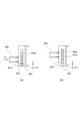
(5)トレイ側コネクタと本体側コネクタの接続動作
次に、トレイ側コネクタ100と本体側コネクタ200の接続動作について説明する。図8(a~c)は、カートリッジトレイ3の装着動作の各段階における、カートリッジトレイ3の位置(左図)と、本体側コネクタ200及びトレイ側コネクタ100の状態(右図)と、を合わせて示したものである。図8(a)はカートリッジトレイ3が引出位置からドラム離間位置へ向けて移動している途中の状態を表し、図8(b)はカートリッジトレイ3がドラム離間位置にある状態を表し、図8(c)はカートリッジトレイ3が装着位置にある状態を表す。
(5) Connection operation between the tray side connector and the main body side connector Next, the connection operation between the
カートリッジトレイ3がガイドレール41に沿って引出位置からドラム離間位置に向かって挿入方向D1に挿入されていくとき、図8(a)に示すように、本体側コネクタ200は上述のバネ部材203に付勢されて上方位置に待機している。さらにカートリッジトレイ3を挿入していくと、ドラム離間位置に到達する前にトレイ側コネクタ100の先端が本体側コネクタ200に到達する。そして、少なくとも図8(b)に示すようにカートリッジトレイ3がドラム離間位置に到達した時点では、トレイ側コネクタ100及び本体側コネクタ200は係合状態(仮接続状態)となっている。ただし、トレイ側コネクタ100及び本体側コネクタ200の端子同士は導通していない。
When the
カートリッジトレイ3がドラム離間位置から装着位置へ向かって装着完了方向D2に移動すると、図8(c)に示すように、トレイ側コネクタ100の装着完了方向D2の移動に伴って本体側コネクタ200はZ方向下方に移動する。また、このとき本体側コネクタ200のY方向の移動は規制されていることから、トレイ側コネクタ100は本体側コネクタ200に対してより深く嵌合し、端子同士が接触する。そして、カートリッジトレイ3が装着位置に到達すると、トレイ側コネクタ100と本体側コネクタ200の接続が完了した状態となっている。
When the
このように、カートリッジトレイ3が装着位置にあるとき、現像カートリッジ8k~8yのメモリタグ81k~81yが、トレイ側コネクタ100及び本体側コネクタ200の接続部を介して装置本体2の制御基板2Cと電気的に接続される。これにより、制御基板2Cは、メモリタグ81k~81kにアクセスして格納されている情報を読み出すことができるようになる。
In this way, when the
(6)本実施例の作用
以上説明した通り、本実施例では、カートリッジトレイ3が引出位置からドラム離間位置へ向けて挿入方向D1に移動している間にトレイ側コネクタ100が本体側コネクタ200と係合する。この構成により、カートリッジトレイ3を装着する際にカートリッジトレイ3と装置本体2を安定して接続することができることを説明する。
(6) Effects of this embodiment As explained above, in this embodiment, while the
比較例として、カートリッジトレイ3がドラム離間位置から装着位置へ向かって装着完了方向D2に移動する際にトレイ側コネクタ100が本体側コネクタ200と係合する構成を考える。しかし、この場合、カートリッジトレイ3がガイドレール41のガイド面41aのガイド作用を受けず、カートリッジトレイ3及び現像カートリッジ8k~8yの重量によって付勢されて斜め下方に移動している状態でコネクタ同士が係合することになる。そのため、接続不良が生じるおそれがある。また、コネクタ同士の位置ずれがあった場合に、コネクタ同士が衝突して破損するおそれがある。
As a comparative example, consider a configuration in which the tray-
これに対し、本実施例では、カートリッジトレイ3がガイドレール41に案内されて装着完了方向D2よりも水平に近い挿入方向D1に移動している間にトレイ側コネクタ100が本体側コネクタ200と係合する。このため、比較例の構成に比べてコネクタ同士をより確実に係合させることができる。
In contrast, in this embodiment, while the
また、本実施例では、本体側コネクタ200及びトレイ側コネクタ100を略水平方向である挿入方向D1の上流に向けた姿勢で配置している。これにより、コネクタ内部に埃等の異物が入り込む可能性を低減して、コネクタ同士の安定した接続に貢献する。
Further, in this embodiment, the main
(7)変形例
上記実施例1では、鉛直方向に変位可能な本体側接点部の例として略鉛直方向にスライドする本体側コネクタ200を例示したが、図9に示すように、鉛直方向に対して交差する移動方向D3にスライドする本体側コネクタ200を用いてもよい。本変形例における本体側コネクタ200のガイド突起201aは、挿入方向D1に対して下方に傾斜した移動方向D3に延びるガイドレール202aによって案内される。移動方向D3は、装着完了方向D2と略同一方向としてもよいし、装着完了方向D2と鉛直方向(下方向)との間の方向としてもよい。このような構成によっても、カートリッジトレイ3が挿入方向D1に移動している間にトレイ側コネクタ100が本体側コネクタ200と係合する構成とすることで、コネクタ同士の安定した接続を実現できる。
(7) Modification In the above-mentioned Example 1, the main
また、上記実施例1において、カートリッジトレイ3の挿入方向D1は略水平方向であるものとして説明したが、挿入方向D1が水平方向に対して傾斜していてもよい。例えば、挿入方向D1がY方向の背面側に向かって下方に傾斜しており、装着完了方向D2が、挿入方向D1よりさらに急な角度で下方に傾斜している構成であってもよい。
Further, in the first embodiment, the insertion direction D1 of the
また、上記実施例1では、カートリッジトレイ3の装着動作が挿入方向D1の動きと装着完了方向D2の動きの2段階で構成されるものとして説明した。これに限らず、例えばカートリッジトレイ3の移動方向が挿入方向D1から装着完了方向D2に連続的に変化するようにガイドレール等が形成されていてもよい。その場合、「第2方向」とは、カートリッジトレイ3が装着位置(第3位置)に到達するときの移動方向である。「第1方向」とは、カートリッジトレイ3の移動軌跡において第2方向に移動する部分より上流側で、水平方向に対する傾きが第2方向の水平方向に対する傾きより小さいいずれかの部分である。
Furthermore, in the first embodiment, the mounting operation of the
なお、トレイ側コネクタ100及び本体側コネクタ200としては、一般にドロワーコネクタとして知られるコネクタ構成を好適に用いることができる。ドロワーコネクタは、端子同士の接続に先立って嵌合するガイド機構を有するコネクタである。
Note that as the
実施例2に係る画像形成装置について、図10及び図11(a~c)を用いて説明する。本実施例は、トレイ側コネクタが移動可能で、本体側コネクタの位置が固定されている点で実施例1と異なっている。以下、実施例1と共通の符号を付した要素は実施例1と同様の構成及び作用を有するものとし、実施例1と異なる部分を中心に説明する。 An image forming apparatus according to a second embodiment will be explained using FIGS. 10 and 11(a to c). This embodiment differs from the first embodiment in that the tray side connector is movable and the main body side connector is fixed in position. Hereinafter, elements with the same reference numerals as those in the first embodiment have the same configurations and functions as those in the first embodiment, and the description will focus on parts that are different from the first embodiment.
図10は実施例2のカートリッジトレイ3を示す斜視図である。実施例1と同様に、挿入方向D1におけるカートリッジトレイ3の下流側(先端側)にトレイ側コネクタ100が配置されている。カートリッジトレイ3に装着された現像カートリッジ8k~8yのメモリタグ81k~81yは、トレイメモリ接点82k~82y及び不図示の中継基板を介してトレイ側コネクタ100に電気的に接続されている。同様に、カートリッジトレイ3に設けられた不図示のドラムメモリタグもトレイ側コネクタ100に電気的に接続されている。
FIG. 10 is a perspective view showing the
本実施例のトレイ側コネクタ100は、カートリッジトレイ3のトレイ枠体30に対してZ方向に揺動可能に設けられている。具体的には、トレイ側コネクタ100はコネクタホルダ302に取り付けられており、コネクタホルダ302は、移動方向を略鉛直方向に規制された状態でトレイ枠体30のリアフレーム301に支持されている。コネクタホルダ302とリアフレーム301の間には、付勢手段としてのバネ部材303が配置されており、コネクタホルダ302はバネ部材303によって下方に付勢されている。このため、カートリッジトレイ3が引出位置にあるとき、トレイ側コネクタ100は移動範囲の下方位置で待機する。
The tray-
一方、図11のように本体側コネクタ200は装置本体2の枠体に固定されたコネクタ固定ホルダ304に取り付けられており、装置本体2に対する位置が固定されている。また、配線部材を介して装置本体2の制御基板2Cと電気的に接続されている。Z方向における本体側コネクタ200の高さは、下方位置にあるトレイ側コネクタ100の高さと略一致する。
On the other hand, as shown in FIG. 11, the main
本実施例におけるコネクタの接続動作を説明する。図11(a)はカートリッジトレイ3が引出位置からドラム離間位置へ向けて移動している途中の状態を表し、図11(b)はカートリッジトレイ3がドラム離間位置にある状態を表し、図11(c)はカートリッジトレイ3が装着位置にある状態を表す。
The connection operation of the connector in this embodiment will be explained. 11(a) shows a state in which the
カートリッジトレイ3がガイドレール41に沿って引出位置からドラム離間位置に向かって挿入方向D1に挿入されていくとき、図11(a)に示すように、トレイ側コネクタ100は上述のバネ部材303に付勢されて下方位置に待機している。さらにカートリッジトレイ3を挿入していくと、ドラム離間位置に到達する前にトレイ側コネクタ100の先端が本体側コネクタ200に到達する。そして、少なくとも図11(b)に示すようにカートリッジトレイ3がドラム離間位置に到達した時点では、トレイ側コネクタ100及び本体側コネクタ200は係合状態(仮接続状態)となっている。ただし、トレイ側コネクタ100及び本体側コネクタ200の端子同士は導通していない。また、引出位置からドラム離間位置までは、感光ドラム4k~4yが静電吸着ベルト12から離間した状態のまま、カートリッジトレイ3が略水平方向である挿入方向D1に移動する。
When the
カートリッジトレイ3がさらに挿入されると、図11(c)に示すように、トレイ側コネクタ100と本体側コネクタ200の係合状態が維持されたまま、カートリッジトレイ3はドラム離間位置から装着位置へ装着完了方向D2に移動する。このとき、トレイ側コネクタ100は、カートリッジトレイ3のリアフレーム301に対してZ方向上方に相対移動する。また、カートリッジトレイ3は、Y方向の背面側に向かって下方に傾斜した装着完了方向D2に移動するため、トレイ側コネクタ100はY方向の背面側に移動して、本体側コネクタ200とより深く嵌合し、端子同士が接触する。そして、カートリッジトレイ3が装着位置に到達すると、トレイ側コネクタ100と本体側コネクタ200の接続が完了した状態となっている。
When the
以上説明したように、実施例2においても、カートリッジトレイ3が挿入方向D1に移動している間にトレイ側コネクタ100と本体側コネクタ200が係合する構成としたため、コネクタ同士の安定した接続を実現することができる。また、本実施例においても、コネクタ同士は略水平方向を向いて配置されるため、コネクタ内部への埃等の異物の侵入を低減してより安定した接続を実現することができる。
As explained above, in the second embodiment as well, the
(変形例)
なお、実施例2では付勢手段としてのバネ部材303によってトレイ側コネクタ100を下方に付勢しているが、例えば、本体側コネクタ200から離脱したトレイ側コネクタ100が自重によって下方位置に待機する構成としてもよい。
(Modified example)
In the second embodiment, the tray-
(その他の実施形態)
上記実施例1、2では、現像カートリッジが感光ドラムを有するカートリッジトレイに着脱される構成を例示した。これに限らず、感光ドラム及びドラムメモリタグを有するカートリッジ(現像カートリッジと一体化されたプロセスカートリッジや現像カートリッジとは別の感光体カートリッジ)が、感光ドラムを有していないトレイに着脱される構成としてもよい。
(Other embodiments)
In the first and second embodiments described above, the configuration in which the developer cartridge is attached to and detached from a cartridge tray having a photosensitive drum was exemplified. The present invention is not limited to this, and the configuration is such that a cartridge having a photosensitive drum and a drum memory tag (a process cartridge integrated with a developing cartridge or a photosensitive cartridge separate from the developing cartridge) is attached to and removed from a tray that does not include a photosensitive drum. You can also use it as
また、上記実施例1、2における静電吸着ベルト12は画像形成装置が備えるベルト部材の一例であり、例えば中間転写体である中間転写ベルトを備える画像形成装置に本技術を適用してもよい。この場合、カートリッジトレイ3が装着位置にあるときは感光ドラムが中間転写ベルトに接触し、カートリッジトレイ3がドラム離間位置と引出位置との間で移動するときは感光ドラムが中間転写ベルトから離間するようにすると好適である。
Further, the
また、上記実施例1、2では、カートリッジトレイ3がガイドレール41の傾斜面41b等に沿って装着位置(第3位置)に到達した時点で感光ドラム4k~4yが静電吸着ベルト12と接触するものとして説明した。これに代えて、例えばカートリッジトレイ3が装着位置に到達した時点では感光ドラムが静電吸着ベルト12と接触せず、前ドア40を閉じる動作に連動してカートリッジトレイ3又は静電吸着ベルト12が移動することで感光ドラムと静電吸着ベルト12が接触するようにしてもよい。
Further, in the first and second embodiments, the
1…画像形成装置/2…装置本体/2C…制御部(制御基板)/3…感光体ユニット(カートリッジトレイ)/4k、4c、4m、4y…感光体(感光ドラム)/6k、6c、6m、6y…現像ローラ/8k、8c、8m、8y…現像カートリッジ/12…ベルト部材(静電吸着ベルト)/41…ガイド手段(ガイドレール)/41a…ガイド面/41b…傾斜面/50…被案内部(ガイドコロ)/81k、81c、81m、81c…記憶媒体(メモリタグ)/89k、89c、89m、89y…装着部(カートリッジ収容部)/100…感光体ユニット側接点部(トレイ側コネクタ)/200…本体側接点部(本体側コネクタ)/203…付勢手段(バネ部材)/D1…第1方向(挿入方向)/D2…第2方向(装着完了方向) 1...Image forming apparatus/2...Device main body/2C...Control unit (control board)/3...Photoconductor unit (cartridge tray)/4k, 4c, 4m, 4y...Photoconductor (photosensitive drum)/6k, 6c, 6m , 6y...Developing roller/8k, 8c, 8m, 8y...Developing cartridge/12...Belt member (electrostatic adsorption belt)/41...Guide means (guide rail)/41a...Guide surface/41b...Slanted surface/50...Surface Guide part (guide roller) /81k, 81c, 81m, 81c... Storage medium (memory tag) /89k, 89c, 89m, 89y... Mounting part (cartridge storage part) / 100... Photoconductor unit side contact part (tray side connector )/200...Body side contact portion (main body side connector)/203...Biasing means (spring member)/D1...First direction (insertion direction)/D2...Second direction (installation completion direction)
Claims (9)
前記装置本体に装着された感光体ユニットであって、回転軸線を中心に回転可能な感光体を有し、前記装置本体に対して前記回転軸線の方向と交差する方向に移動する感光体ユニットと、
前記装置本体に設けられ、前記装置本体に対して前記感光体ユニットが移動させられる時に前記感光体ユニットをガイドするガイド手段と、
前記感光体ユニットに設けられた装着部に着脱可能に構成される現像カートリッジであって、現像剤を収容する筐体と、前記筐体に収容された前記現像剤を用いて前記感光体上の静電潜像を現像する現像ローラと、現像カートリッジに関する情報を記憶する記憶媒体と、を有する現像カートリッジと、
前記感光体ユニットに設けられた第1コネクタであって、前記現像カートリッジが前記感光体ユニットに装着された状態で前記記憶媒体と電気的に接続される第1接点端子を有し、前記感光体ユニットに対して上下方向に移動可能な第1コネクタと、
前記装置本体に設けられた第2コネクタであって、前記制御部と電気的に接続された第2接点端子を有し、前記第1接点端子と前記第2接点端子が接触するように前記第1コネクタと係合可能な第2コネクタと、
を備えた画像形成装置であって、
前記感光体ユニットは、前記ガイド手段によってガイドされながら着脱位置から画像形成位置に移動するように構成され、前記着脱位置は、前記装着部に対する前記現像カートリッジの着脱が可能となる位置であり、前記画像形成位置は、前記第1コネクタの前記第1接点端子と前記第2コネクタの前記第2接点端子が接触し且つ前記画像形成装置が画像形成動作を実行可能となる位置であって、前記着脱位置よりも下方の位置であり、
前記第1コネクタは、前記回転軸線の方向に見た時に、水平方向において前記着脱位置から前記画像形成位置に向かう方向における前記感光体ユニットの端部に設けられており、
前記感光体ユニットは、前記着脱位置から前記画像形成位置に移動する過程で前記感光体ユニットの前記端部の移動方向が前記水平方向に対して下向きに傾くように、前記ガイド手段によってガイドされ、
前記第1コネクタ及び前記第2コネクタは、前記感光体ユニットが前記着脱位置から前記画像形成位置に移動させられている間に、前記感光体ユニットの前記端部の前記移動方向の前記水平方向に対する下向きの角度が最大角度となる前に、互いに係合するように構成されている、
ことを特徴とする画像形成装置。 a device main body having a control section;
A photoreceptor unit mounted on the apparatus main body , the photoreceptor unit having a photoreceptor rotatable around a rotation axis and moving in a direction intersecting the direction of the rotation axis with respect to the apparatus main body. and,
a guide means provided in the apparatus main body and for guiding the photoreceptor unit when the photoreceptor unit is moved relative to the apparatus main body;
The developer cartridge is configured to be removably attached to a mounting portion provided on the photoconductor unit, and includes a casing for accommodating a developer, and a developer cartridge that uses the developer accommodated in the casing to develop an image on the photoconductor. a developer cartridge having a developer roller that develops an electrostatic latent image; and a storage medium that stores information regarding the developer cartridge;
a first connector provided on the photoreceptor unit, the first connector having a first contact terminal electrically connected to the storage medium when the developer cartridge is attached to the photoreceptor unit; a first connector that is movable vertically with respect to the unit;
a second connector provided on the device main body, the second connector having a second contact terminal electrically connected to the control unit, and the second connector configured to connect the first contact terminal and the second contact terminal; a second connector that is engageable with the first connector;
An image forming apparatus comprising:
The photoreceptor unit is configured to move from an attachment/detachment position to an image forming position while being guided by the guide means, and the attachment/detachment position is a position where the developer cartridge can be attached/detached to/from the mounting portion; The image forming position is a position where the first contact terminal of the first connector and the second contact terminal of the second connector are in contact with each other and the image forming apparatus can perform an image forming operation, The position is lower than the
The first connector is provided at an end of the photoreceptor unit in a horizontal direction from the attachment/detachment position toward the image forming position when viewed in the direction of the rotation axis,
The photoreceptor unit is guided by the guide means such that the moving direction of the end portion of the photoreceptor unit is tilted downward with respect to the horizontal direction during the process of moving from the attachment/detachment position to the image forming position;
The first connector and the second connector are connected to each other in the moving direction of the end portion of the photoreceptor unit with respect to the horizontal direction while the photoreceptor unit is being moved from the attachment/detachment position to the image forming position. configured to engage each other before the downward angle reaches the maximum angle;
An image forming apparatus characterized by:
ことを特徴とする請求項1に記載の画像形成装置。 The first connector and the second connector are configured to engage with each other when a downward angle of the moving direction of the end portion of the photoreceptor unit with respect to the horizontal direction is a first angle smaller than the maximum angle. is composed of
The image forming apparatus according to claim 1, characterized in that:
ことを特徴とする請求項1に記載の画像形成装置。 The first connector and the second connector are configured to engage with each other when the moving direction of the end portion of the photoreceptor unit is the horizontal direction.
The image forming apparatus according to claim 1, characterized in that:
ことを特徴とする請求項1から3のいずれか1項に記載の画像形成装置。 The first connector moves upward with respect to the photoreceptor unit in the process of moving the photoreceptor unit from the attachment/detachment position to the image forming position.
The image forming apparatus according to any one of claims 1 to 3.
前記感光体ユニットが前記着脱位置にある場合は前記感光体が前記ベルト部材に接触しておらず、前記感光体ユニットが前記画像形成位置にある場合は前記感光体が前記ベルト部材に接触する、
ことを特徴とする請求項1から4のいずれか1項に記載の画像形成装置。 The apparatus main body includes a belt member disposed below the photoreceptor unit,
When the photoreceptor unit is at the attachment/detachment position, the photoreceptor is not in contact with the belt member, and when the photoreceptor unit is at the image forming position, the photoreceptor is in contact with the belt member.
The image forming apparatus according to any one of claims 1 to 4.
ことを特徴とする請求項5に記載の画像形成装置。 When the photoreceptor unit is at the image forming position, a nip portion is formed between the belt member and the photoreceptor, through which a recording medium to which a toner image is transferred from the photoreceptor passes.
The image forming apparatus according to claim 5, characterized in that:
ことを特徴とする請求項1から6のいずれか1項に記載の画像形成装置。 The photoreceptor unit further includes a biasing member that biases the first connector downward .
The image forming apparatus according to any one of claims 1 to 6.
ことを特徴とする請求項1から7のいずれか1項に記載の画像形成装置。 the second connector is configured not to move in the vertical direction;
The image forming apparatus according to any one of claims 1 to 7.
ことを特徴とする請求項1から8のいずれか1項に記載の画像形成装置。 While the photoreceptor unit is being moved from the attachment/detachment position to the image forming position, before the downward angle of the moving direction of the end portion of the photoreceptor unit with respect to the horizontal direction reaches the maximum angle, the first contact terminal and the second contact terminal are not in contact with each other;
The image forming apparatus according to any one of claims 1 to 8.
Priority Applications (7)
| Application Number | Priority Date | Filing Date | Title |
|---|---|---|---|
| JP2020038853A JP7413089B2 (en) | 2020-03-06 | 2020-03-06 | Image forming device |
| US17/172,512 US11513468B2 (en) | 2020-03-06 | 2021-02-10 | Image forming apparatus having displaceable electrical contact when mounting photoconductor unit |
| CN202311268023.6A CN117092899A (en) | 2020-03-06 | 2021-03-02 | Image forming apparatus |
| CN202110229593.9A CN113359402B (en) | 2020-03-06 | 2021-03-02 | Image forming apparatus |
| US17/973,189 US11874629B2 (en) | 2020-03-06 | 2022-10-25 | Image forming apparatus having photoconductor unit and removable developing cartridge |
| US18/530,966 US20240111246A1 (en) | 2020-03-06 | 2023-12-06 | Image forming apparatus |
| JP2023221608A JP2024026586A (en) | 2020-03-06 | 2023-12-27 | Image forming device |
Applications Claiming Priority (1)
| Application Number | Priority Date | Filing Date | Title |
|---|---|---|---|
| JP2020038853A JP7413089B2 (en) | 2020-03-06 | 2020-03-06 | Image forming device |
Related Child Applications (1)
| Application Number | Title | Priority Date | Filing Date |
|---|---|---|---|
| JP2023221608A Division JP2024026586A (en) | 2020-03-06 | 2023-12-27 | Image forming device |
Publications (3)
| Publication Number | Publication Date |
|---|---|
| JP2021140070A JP2021140070A (en) | 2021-09-16 |
| JP2021140070A5 JP2021140070A5 (en) | 2023-08-31 |
| JP7413089B2 true JP7413089B2 (en) | 2024-01-15 |
Family
ID=77524790
Family Applications (2)
| Application Number | Title | Priority Date | Filing Date |
|---|---|---|---|
| JP2020038853A Active JP7413089B2 (en) | 2020-03-06 | 2020-03-06 | Image forming device |
| JP2023221608A Pending JP2024026586A (en) | 2020-03-06 | 2023-12-27 | Image forming device |
Family Applications After (1)
| Application Number | Title | Priority Date | Filing Date |
|---|---|---|---|
| JP2023221608A Pending JP2024026586A (en) | 2020-03-06 | 2023-12-27 | Image forming device |
Country Status (3)
| Country | Link |
|---|---|
| US (3) | US11513468B2 (en) |
| JP (2) | JP7413089B2 (en) |
| CN (2) | CN117092899A (en) |
Families Citing this family (1)
| Publication number | Priority date | Publication date | Assignee | Title |
|---|---|---|---|---|
| JP2022126270A (en) * | 2021-02-18 | 2022-08-30 | 沖電気工業株式会社 | Image forming apparatus |
Citations (12)
| Publication number | Priority date | Publication date | Assignee | Title |
|---|---|---|---|---|
| JP2001034144A (en) | 1999-07-23 | 2001-02-09 | Canon Inc | Image forming device and process cartridge |
| JP2003195726A (en) | 2001-12-28 | 2003-07-09 | Canon Inc | Image forming apparatus and process cartridge |
| JP2006065267A (en) | 2004-07-30 | 2006-03-09 | Canon Inc | Process cartridge and electrophotographic image forming apparatus |
| JP2007213018A (en) | 2006-01-11 | 2007-08-23 | Canon Inc | Color electrophotographic image forming apparatus |
| JP2011064925A (en) | 2009-09-17 | 2011-03-31 | Brother Industries Ltd | Image forming apparatus and electrode member with the same |
| JP2011118119A (en) | 2009-12-02 | 2011-06-16 | Oki Data Corp | Image forming apparatus |
| JP2013246399A (en) | 2012-05-29 | 2013-12-09 | Brother Ind Ltd | Image forming apparatus |
| JP2014119505A (en) | 2012-12-13 | 2014-06-30 | Canon Inc | Image forming apparatus |
| JP2015163983A (en) | 2010-06-11 | 2015-09-10 | 株式会社リコー | Information storage device and detachable device |
| JP2016075752A (en) | 2014-10-03 | 2016-05-12 | キヤノン株式会社 | Image forming apparatus |
| JP2018205508A (en) | 2017-06-02 | 2018-12-27 | キヤノン株式会社 | Unit attachment/detachment mechanism and image formation apparatus |
| JP2019124969A (en) | 2019-05-08 | 2019-07-25 | キヤノン株式会社 | Image forming apparatus |
Family Cites Families (14)
| Publication number | Priority date | Publication date | Assignee | Title |
|---|---|---|---|---|
| JPH11143337A (en) * | 1997-11-07 | 1999-05-28 | Canon Inc | Process cartridge and electrophotographic image forming device |
| JP2008145502A (en) * | 2006-12-06 | 2008-06-26 | Brother Ind Ltd | Image forming apparatus |
| JP4725590B2 (en) * | 2008-03-25 | 2011-07-13 | ブラザー工業株式会社 | Image forming apparatus and photoreceptor unit |
| JP5762054B2 (en) * | 2010-03-16 | 2015-08-12 | キヤノン株式会社 | Process cartridge and image forming apparatus |
| GB2510033B (en) * | 2012-11-28 | 2015-02-25 | Canon Kk | Image forming apparatus |
| CN104375399B (en) * | 2013-08-13 | 2018-08-07 | 兄弟工业株式会社 | Image forming apparatus |
| JP6128044B2 (en) * | 2014-03-31 | 2017-05-17 | ブラザー工業株式会社 | Image forming apparatus |
| US9360834B1 (en) * | 2015-09-15 | 2016-06-07 | Lexmark International, Inc. | Replaceable unit for an electrophotographic image forming device having positioning features for electrical contacts |
| JP6707877B2 (en) * | 2016-02-02 | 2020-06-10 | ブラザー工業株式会社 | Image forming device |
| KR20180051940A (en) * | 2016-11-09 | 2018-05-17 | 에이치피프린팅코리아 주식회사 | Image forming apparatus |
| US10139776B1 (en) * | 2017-05-11 | 2018-11-27 | Lexmark International, Inc. | Electrical connector assembly for use in an image forming device |
| JP7047277B2 (en) | 2017-08-01 | 2022-04-05 | ブラザー工業株式会社 | Drum unit and image forming device |
| JP2019117346A (en) * | 2017-12-27 | 2019-07-18 | ブラザー工業株式会社 | Drum cartridge and image forming apparatus |
| US10649389B1 (en) * | 2019-04-12 | 2020-05-12 | Lexmark International, Inc. | Electrical connectors of a replaceable unit of an electrophotographic image forming device |
-
2020
- 2020-03-06 JP JP2020038853A patent/JP7413089B2/en active Active
-
2021
- 2021-02-10 US US17/172,512 patent/US11513468B2/en active Active
- 2021-03-02 CN CN202311268023.6A patent/CN117092899A/en active Pending
- 2021-03-02 CN CN202110229593.9A patent/CN113359402B/en active Active
-
2022
- 2022-10-25 US US17/973,189 patent/US11874629B2/en active Active
-
2023
- 2023-12-06 US US18/530,966 patent/US20240111246A1/en active Pending
- 2023-12-27 JP JP2023221608A patent/JP2024026586A/en active Pending
Patent Citations (12)
| Publication number | Priority date | Publication date | Assignee | Title |
|---|---|---|---|---|
| JP2001034144A (en) | 1999-07-23 | 2001-02-09 | Canon Inc | Image forming device and process cartridge |
| JP2003195726A (en) | 2001-12-28 | 2003-07-09 | Canon Inc | Image forming apparatus and process cartridge |
| JP2006065267A (en) | 2004-07-30 | 2006-03-09 | Canon Inc | Process cartridge and electrophotographic image forming apparatus |
| JP2007213018A (en) | 2006-01-11 | 2007-08-23 | Canon Inc | Color electrophotographic image forming apparatus |
| JP2011064925A (en) | 2009-09-17 | 2011-03-31 | Brother Industries Ltd | Image forming apparatus and electrode member with the same |
| JP2011118119A (en) | 2009-12-02 | 2011-06-16 | Oki Data Corp | Image forming apparatus |
| JP2015163983A (en) | 2010-06-11 | 2015-09-10 | 株式会社リコー | Information storage device and detachable device |
| JP2013246399A (en) | 2012-05-29 | 2013-12-09 | Brother Ind Ltd | Image forming apparatus |
| JP2014119505A (en) | 2012-12-13 | 2014-06-30 | Canon Inc | Image forming apparatus |
| JP2016075752A (en) | 2014-10-03 | 2016-05-12 | キヤノン株式会社 | Image forming apparatus |
| JP2018205508A (en) | 2017-06-02 | 2018-12-27 | キヤノン株式会社 | Unit attachment/detachment mechanism and image formation apparatus |
| JP2019124969A (en) | 2019-05-08 | 2019-07-25 | キヤノン株式会社 | Image forming apparatus |
Also Published As
| Publication number | Publication date |
|---|---|
| JP2024026586A (en) | 2024-02-28 |
| US11513468B2 (en) | 2022-11-29 |
| CN117092899A (en) | 2023-11-21 |
| US20210278801A1 (en) | 2021-09-09 |
| US11874629B2 (en) | 2024-01-16 |
| US20240111246A1 (en) | 2024-04-04 |
| US20230185235A1 (en) | 2023-06-15 |
| CN113359402A (en) | 2021-09-07 |
| JP2021140070A (en) | 2021-09-16 |
| CN113359402B (en) | 2023-10-24 |
Similar Documents
| Publication | Publication Date | Title |
|---|---|---|
| US7567769B2 (en) | Electrophotographic color image forming apparatus | |
| US7715746B2 (en) | Process cartridge having electrical contact and image forming apparatus having electrical contact in urging member | |
| KR100890222B1 (en) | Electrophotographic image forming apparatus | |
| US8526841B2 (en) | Process cartridge and electrophotographic image forming apparatus | |
| US8139979B2 (en) | Process cartridge and electrophotographic image forming apparatus | |
| US8290395B2 (en) | Electrophotographic image forming apparatus | |
| KR101721013B1 (en) | Image forming apparatus | |
| US8526848B2 (en) | Electrophotographic image forming apparatus | |
| JP5565011B2 (en) | Image forming apparatus | |
| US8437660B2 (en) | Image forming apparatus with movable member for supporting cartridges | |
| JP2024026586A (en) | Image forming device | |
| US9223242B2 (en) | Image forming apparatus | |
| US10459401B2 (en) | Image forming apparatus | |
| JP5871178B2 (en) | Developer supply device and image forming apparatus | |
| US8452206B2 (en) | Image-forming apparatus with improved positioning for medium conveyance | |
| JP2006151657A (en) | Paper feed cassette and image forming apparatus | |
| JP2021107914A (en) | Cartridge unit | |
| JPH03269552A (en) | Color image forming device |
Legal Events
| Date | Code | Title | Description |
|---|---|---|---|
| A621 | Written request for application examination |
Free format text: JAPANESE INTERMEDIATE CODE: A621 Effective date: 20230303 |
|
| A521 | Request for written amendment filed |
Free format text: JAPANESE INTERMEDIATE CODE: A523 Effective date: 20230823 |
|
| A871 | Explanation of circumstances concerning accelerated examination |
Free format text: JAPANESE INTERMEDIATE CODE: A871 Effective date: 20230823 |
|
| A131 | Notification of reasons for refusal |
Free format text: JAPANESE INTERMEDIATE CODE: A131 Effective date: 20230919 |
|
| A521 | Request for written amendment filed |
Free format text: JAPANESE INTERMEDIATE CODE: A523 Effective date: 20231115 |
|
| TRDD | Decision of grant or rejection written | ||
| A01 | Written decision to grant a patent or to grant a registration (utility model) |
Free format text: JAPANESE INTERMEDIATE CODE: A01 Effective date: 20231128 |
|
| A61 | First payment of annual fees (during grant procedure) |
Free format text: JAPANESE INTERMEDIATE CODE: A61 Effective date: 20231227 |
|
| R151 | Written notification of patent or utility model registration |
Ref document number: 7413089 Country of ref document: JP Free format text: JAPANESE INTERMEDIATE CODE: R151 |