JP7411069B2 - Washpipe system and method - Google Patents
Washpipe system and method Download PDFInfo
- Publication number
- JP7411069B2 JP7411069B2 JP2022515796A JP2022515796A JP7411069B2 JP 7411069 B2 JP7411069 B2 JP 7411069B2 JP 2022515796 A JP2022515796 A JP 2022515796A JP 2022515796 A JP2022515796 A JP 2022515796A JP 7411069 B2 JP7411069 B2 JP 7411069B2
- Authority
- JP
- Japan
- Prior art keywords
- seal
- rotating
- internal cavity
- carrier
- rotating seal
- Prior art date
- Legal status (The legal status is an assumption and is not a legal conclusion. Google has not performed a legal analysis and makes no representation as to the accuracy of the status listed.)
- Active
Links
- 238000000034 method Methods 0.000 title description 12
- 239000012530 fluid Substances 0.000 claims description 103
- 238000005553 drilling Methods 0.000 claims description 26
- XLYOFNOQVPJJNP-UHFFFAOYSA-N water Substances O XLYOFNOQVPJJNP-UHFFFAOYSA-N 0.000 claims description 12
- 238000004891 communication Methods 0.000 claims description 7
- 238000011144 upstream manufacturing Methods 0.000 claims 2
- 230000003416 augmentation Effects 0.000 description 6
- 238000009412 basement excavation Methods 0.000 description 4
- 230000006870 function Effects 0.000 description 4
- 238000007789 sealing Methods 0.000 description 4
- 238000010586 diagram Methods 0.000 description 3
- 239000010720 hydraulic oil Substances 0.000 description 3
- 238000012856 packing Methods 0.000 description 3
- 230000000712 assembly Effects 0.000 description 2
- 238000000429 assembly Methods 0.000 description 2
- 238000001816 cooling Methods 0.000 description 2
- 230000006378 damage Effects 0.000 description 2
- 239000007788 liquid Substances 0.000 description 2
- 230000007246 mechanism Effects 0.000 description 2
- 230000037361 pathway Effects 0.000 description 2
- 230000003014 reinforcing effect Effects 0.000 description 2
- 238000012546 transfer Methods 0.000 description 2
- 244000261422 Lysimachia clethroides Species 0.000 description 1
- 230000008901 benefit Effects 0.000 description 1
- 230000015572 biosynthetic process Effects 0.000 description 1
- 239000000969 carrier Substances 0.000 description 1
- 238000011109 contamination Methods 0.000 description 1
- 230000008878 coupling Effects 0.000 description 1
- 238000010168 coupling process Methods 0.000 description 1
- 238000005859 coupling reaction Methods 0.000 description 1
- 238000005520 cutting process Methods 0.000 description 1
- 230000006866 deterioration Effects 0.000 description 1
- 239000010687 lubricating oil Substances 0.000 description 1
- 238000005461 lubrication Methods 0.000 description 1
- 238000012986 modification Methods 0.000 description 1
- 230000004048 modification Effects 0.000 description 1
- 230000003068 static effect Effects 0.000 description 1
Images


Classifications
-
- E—FIXED CONSTRUCTIONS
- E21—EARTH OR ROCK DRILLING; MINING
- E21B—EARTH OR ROCK DRILLING; OBTAINING OIL, GAS, WATER, SOLUBLE OR MELTABLE MATERIALS OR A SLURRY OF MINERALS FROM WELLS
- E21B21/00—Methods or apparatus for flushing boreholes, e.g. by use of exhaust air from motor
- E21B21/01—Arrangements for handling drilling fluids or cuttings outside the borehole, e.g. mud boxes
-
- F—MECHANICAL ENGINEERING; LIGHTING; HEATING; WEAPONS; BLASTING
- F16—ENGINEERING ELEMENTS AND UNITS; GENERAL MEASURES FOR PRODUCING AND MAINTAINING EFFECTIVE FUNCTIONING OF MACHINES OR INSTALLATIONS; THERMAL INSULATION IN GENERAL
- F16L—PIPES; JOINTS OR FITTINGS FOR PIPES; SUPPORTS FOR PIPES, CABLES OR PROTECTIVE TUBING; MEANS FOR THERMAL INSULATION IN GENERAL
- F16L27/00—Adjustable joints; Joints allowing movement
- F16L27/08—Adjustable joints; Joints allowing movement allowing adjustment or movement only about the axis of one pipe
- F16L27/0804—Adjustable joints; Joints allowing movement allowing adjustment or movement only about the axis of one pipe the fluid passing axially from one joint element to another
- F16L27/0808—Adjustable joints; Joints allowing movement allowing adjustment or movement only about the axis of one pipe the fluid passing axially from one joint element to another the joint elements extending coaxially for some distance from their point of separation
- F16L27/0812—Adjustable joints; Joints allowing movement allowing adjustment or movement only about the axis of one pipe the fluid passing axially from one joint element to another the joint elements extending coaxially for some distance from their point of separation with slide bearings
- F16L27/082—Adjustable joints; Joints allowing movement allowing adjustment or movement only about the axis of one pipe the fluid passing axially from one joint element to another the joint elements extending coaxially for some distance from their point of separation with slide bearings having axial sealing
-
- E—FIXED CONSTRUCTIONS
- E21—EARTH OR ROCK DRILLING; MINING
- E21B—EARTH OR ROCK DRILLING; OBTAINING OIL, GAS, WATER, SOLUBLE OR MELTABLE MATERIALS OR A SLURRY OF MINERALS FROM WELLS
- E21B21/00—Methods or apparatus for flushing boreholes, e.g. by use of exhaust air from motor
- E21B21/02—Swivel joints in hose-lines
-
- F—MECHANICAL ENGINEERING; LIGHTING; HEATING; WEAPONS; BLASTING
- F16—ENGINEERING ELEMENTS AND UNITS; GENERAL MEASURES FOR PRODUCING AND MAINTAINING EFFECTIVE FUNCTIONING OF MACHINES OR INSTALLATIONS; THERMAL INSULATION IN GENERAL
- F16L—PIPES; JOINTS OR FITTINGS FOR PIPES; SUPPORTS FOR PIPES, CABLES OR PROTECTIVE TUBING; MEANS FOR THERMAL INSULATION IN GENERAL
- F16L27/00—Adjustable joints; Joints allowing movement
- F16L27/08—Adjustable joints; Joints allowing movement allowing adjustment or movement only about the axis of one pipe
- F16L27/0804—Adjustable joints; Joints allowing movement allowing adjustment or movement only about the axis of one pipe the fluid passing axially from one joint element to another
- F16L27/0808—Adjustable joints; Joints allowing movement allowing adjustment or movement only about the axis of one pipe the fluid passing axially from one joint element to another the joint elements extending coaxially for some distance from their point of separation
Landscapes
- Engineering & Computer Science (AREA)
- General Engineering & Computer Science (AREA)
- Mechanical Engineering (AREA)
- Mining & Mineral Resources (AREA)
- Life Sciences & Earth Sciences (AREA)
- Geology (AREA)
- Fluid Mechanics (AREA)
- Environmental & Geological Engineering (AREA)
- Physics & Mathematics (AREA)
- General Life Sciences & Earth Sciences (AREA)
- Geochemistry & Mineralogy (AREA)
- Mechanical Sealing (AREA)
- Joints Allowing Movement (AREA)
- Earth Drilling (AREA)
Description
関連出願への相互参照
この特許出願は、参照することにより組み込まれる2019年9月10日付出願の米国仮特許出願第62/898,223号の利益を主張する。
CROSS-REFERENCE TO RELATED APPLICATIONS This patent application claims the benefit of U.S. Provisional Patent Application No. 62/898,223, filed September 10, 2019, which is incorporated by reference.
本開示の技術分野
本願の開示は、抗井掘削のトップドライブシステムに関わり、より具体的には、掘削用流体管に沿って、回転可能な境界面を密閉するためのウォッシュパイプシステム及び方法に関わる。
TECHNICAL FIELD OF THE DISCLOSURE The present disclosure relates to top drive systems for well drilling, and more particularly to washpipe systems and methods for sealing rotatable interfaces along drilling fluid conduits. Involved.
発明の背景
抗井掘削の応用では、通常、地上に延びるドリルストリングの一端に配置される坑井内掘削装置ないし掘削スイベルを使用する。地上では、ドリルストリングの先端をトップドライブに係合させ回転させる。ドリルストリングは通常は中空で、掘削孔を安定化させるための泥水等の掘削用流体やコンクリートを地上から掘削装置または孔の側面に供給できるようになっている。掘削用流体は、掘削スイベルに送られるが、一般に「ウォッシュパイプパッキン(washpipe packing)」アセンブリと呼ばれるシールを有する、「ウォッシュパイプ(washpipe)」と呼ばれる高圧スイベル装置を通過する。このパッキンアセンブリには、静止状態に保持される管状の部品が通常含まれており、その中を通って高圧の掘削用流体が流れる。回転するシールアセンブリである接触リップシールをトップドライブまたはスイベルの主軸に機械的に固定して一緒に回転させると、掘削中の主軸の回転に従って管状のウォッシュパイプの外面に対して動的シールを形成する。
BACKGROUND OF THE INVENTION Well drilling applications typically use a downhole drilling rig or drilling swivel that is placed at one end of a drill string that extends above ground. On the ground, the tip of the drill string engages and rotates with the top drive. The drill string is typically hollow and allows drilling fluids such as mud or concrete to be delivered from the ground to the drilling rig or to the sides of the hole to stabilize the hole. Drilling fluid is routed to the drilling swivel through a high pressure swivel device called a "washpipe" that has a seal commonly called a "washpipe packing" assembly. The packing assembly typically includes a tubular component that is held stationary through which the high pressure drilling fluid flows. A rotating seal assembly, the contact lip seal, is mechanically fixed to the top drive or swivel main shaft and rotated together to form a dynamic seal against the outer surface of the tubular washpipe as the main shaft rotates during excavation. do.
様々な要因が従来のウォッシュパイプパッキンアセンブリが提供するシールの質と揚程に影響し得る。例えば、掘削用流体は通常高圧(例えば、6ないし7kpsi)で提供される。しかも、掘削用流体には、多くの場合、シール境界面を腐食及び/または物理的に摩耗させ得る小砂利が含まれている。高速掘削で発生する摩擦と熱もシールの劣化を加速させる。ウォッシュパイプのシールの損傷は、多くの掘削リグでありがちな掘削用流体の漏出を発生させ、周辺部品や環境に汚染や破壊を起こし得る。 Various factors can affect the quality of seal and lift provided by conventional washpipe packing assemblies. For example, drilling fluids are typically provided at high pressure (eg, 6 to 7 kpsi). Moreover, drilling fluids often contain gravel that can corrode and/or physically wear the seal interface. Friction and heat generated by high-speed drilling also accelerate seal deterioration. Damage to washpipe seals can result in leakage of drilling fluids, which is common in many drilling rigs, and can cause contamination and destruction of surrounding components and the environment.
トップドライブとロータリー掘削において、ウォッシュパイプは、通常、シールハウジング内に含まれる一連の円周シールに密閉して係合する。多くの場合、これらのシールとシールハウジングが回転してもウォッシュパイプは静止状態を保つ。このようなシールアセンブリは、従来、一連の補強用バックアップリングを組み込んだ、一連のシェブロン型エラストマー製補強シールを含んでいる。ある先行技術のシステムでは、1つのシールの片側は完全な液圧に暴露され、反対側は大気圧に暴露される。掘削用泥水の完全な差圧が1つのシールに、そのシールが壊れて次いでアセンブリ中の次のシールが一次シールとしての役割をするまで、作用する。先行技術のスイベルの設計の中には、ウォッシュパイプとシールハウジングを関節で連結できるようにして、起こり得る消耗とオフセットの問題を解決しようとするものもある。 In top drive and rotary drilling, the washpipe typically sealingly engages a series of circumferential seals contained within a seal housing. In many cases, the washpipe remains stationary even as these seals and seal housings rotate. Such seal assemblies conventionally include a series of chevron-type elastomeric reinforcing seals that incorporate a series of reinforcing back-up rings. In some prior art systems, one side of one seal is exposed to full hydraulic pressure and the other side is exposed to atmospheric pressure. The full differential pressure of the drilling mud acts on one seal until it breaks and the next seal in the assembly acts as the primary seal. Some prior art swivel designs attempt to articulate the washpipe and seal housing to solve possible wear and offset problems.
発明の概要
ある側面において、本開示は、回転する機械部品と回転しない機械部品の全体に延びている流体管に沿って、それら回転しない機械部品と回転する機械部品の間に配置されるウォッシュパイプシール構造体を記載する。ウォッシュパイプシール構造体は、回転しない機械部品に接続された回転しないフレームを含む。回転しないフレームは、内部空洞を形成する概して中空の円筒形状を有する、回転しないシール担持体を含む。第1の回転しないシールが回転しないシール担持体に接続され、また、第2の回転しないシールが回転しないシール担持体に接続される。第1及び第2の回転しないシールは、内部空洞に、互いに対して間隔を空けて配置される。回転可能なシール担持体は、少なくとも部分的に内部空洞内に回転可能に配置される。第1の回転するシールは、回転可能なシール担持体に接続されて第1の回転しないシールに隣接して配置され、また、第2の回転するシールは、回転可能なシール担持体に接続されて第2の回転しないシールに隣接して配置される。作動中は、第1の回転するシールが第1の回転しないシールに接して、流体管を密閉するように構成されている第1のスライドするメカニカルシールを規定し、また、第2の回転するシールが第2の回転しないシールに接して、流体管から分離されていて、かつ、第1のスライドするメカニカルシールの方に延びている、内部空洞の第1の部分を密閉するように構成されている第2のスライドするメカニカル面シールを規定する。
SUMMARY OF THE INVENTION In one aspect, the present disclosure provides a wash pipe disposed between a non-rotating mechanical component and a rotating mechanical component along a fluid conduit extending across the rotating and non-rotating mechanical component. Describe the seal structure. The washpipe seal structure includes a non-rotating frame connected to non-rotating mechanical parts. The non-rotating frame includes a non-rotating seal carrier having a generally hollow cylindrical shape forming an internal cavity. A first non-rotating seal is connected to the non-rotating seal carrier and a second non-rotating seal is connected to the non-rotating seal carrier. First and second non-rotating seals are spaced apart from each other in the interior cavity. A rotatable seal carrier is rotatably arranged at least partially within the internal cavity. The first rotating seal is connected to the rotatable seal carrier and positioned adjacent the first non-rotating seal, and the second rotating seal is connected to the rotatable seal carrier. and is positioned adjacent the second non-rotating seal. In operation, a first rotating seal contacts a first non-rotating seal to define a first sliding mechanical seal configured to seal the fluid conduit, and a second rotating mechanical seal is configured to seal the fluid conduit. The seal is configured to abut the second non-rotating seal and seal a first portion of the internal cavity that is separated from the fluid conduit and extends toward the first sliding mechanical seal. A second sliding mechanical face seal is defined.
他の側面において、本開示は、掘削作業において泥水管と共に使用するためのウォッシュパイプシール構造体を記載する。泥水管は、トップドライブとドリルストリングの間に延びていてもよい。ウォッシュパイプシール構造体は、トップドライブの回転しない機械部品に接続された回転しないフレームを含み、該回転しないフレームは、内部空洞を形成する、概して中空の円筒形状をした回転しないシール担持体を含んでいる。第1の回転しないシールが回転しないシール担持体に接続され、また、第2の回転しないシールが回転しないシール担持体に接続されている。第1及び第2の回転しないシールは、内部空洞内に互いに対して間隔を空けて配置される。回転可能なシール担持体は、少なくとも部分的に内部空洞内に回転可能に配置される。第1の回転するシールは、回転可能なシール担持体に接続されて第1の回転しないシールに隣接して配置され、また、第2の回転するシールは、回転可能なシール担持体に接続されて第2の回転しないシールに隣接して配置される。 In other aspects, the disclosure describes a washpipe seal structure for use with mud pipes in drilling operations. A mud pipe may extend between the top drive and the drill string. The wash pipe seal structure includes a non-rotating frame connected to a non-rotating mechanical component of a top drive, the non-rotating frame including a generally hollow cylindrical shaped non-rotating seal carrier forming an internal cavity. I'm here. A first non-rotating seal is connected to the non-rotating seal carrier and a second non-rotating seal is connected to the non-rotating seal carrier. The first and second non-rotating seals are spaced apart from each other within the interior cavity. A rotatable seal carrier is rotatably arranged at least partially within the internal cavity. The first rotating seal is connected to the rotatable seal carrier and positioned adjacent the first non-rotating seal, and the second rotating seal is connected to the rotatable seal carrier. and is positioned adjacent the second non-rotating seal.
作動中は、第1の回転するシールが第1の回転しないシールに接して、泥水管を密閉するように構成されている第1のスライドするメカニカルシールを規定し、また、第2の回転するシールが第2の回転しないシールに接して、泥水管から分離されていて、かつ、第1のスライドするメカニカルシールの方に延びている、内部空洞の第1の部分を密閉するように構成されている第2のスライドするメカニカル面シールを規定する。緩衝流体は、泥水管内の泥水の圧力と少なくとも同等以上の圧力で提供される。緩衝流体は、内部空洞の第1の部分に提供される。 In operation, a first rotating seal abuts a first non-rotating seal to define a first sliding mechanical seal configured to seal the mud pipe; The seal is configured to abut the second non-rotating seal and seal a first portion of the internal cavity that is separated from the mud pipe and extends toward the first sliding mechanical seal. A second sliding mechanical face seal is defined. The buffer fluid is provided at a pressure at least equal to or higher than the pressure of the mud water in the mud pipe. A buffer fluid is provided in the first portion of the internal cavity.
さらに他の側面において、本開示は、ウォッシュパイプシール構造体を作動させるための方法を記載する。方法は、泥水管を少なくとも部分的に囲んで配置される少なくとも1つの回転しないシール担持体を提供することを含み、ここで、泥水管は回転する機械部品と回転しない機械部品の全体に延び、かつ、ウォッシュパイプシール構造体が泥水管の少なくとも一区画を形成する。方法は、ウォッシュパイプシール構造体に含まれる2つのシール要素の間に第1のスライドするメカニカル面シールを作製することをさらに含み、第1のスライドするメカニカル面シールが回転する機械部品と回転しない機械部品の間の境界面に配置される。また、方法は、ウォッシュパイプシール構造体に含まれる2つの追加のシール要素の間に第2のメカニカル面シールを作ること、及び、第1及び第2のメカニカル面シールの間のウォッシュパイプシール構造体のハウジング内に、泥水管から独立した空洞を規定することを含む。この方法に従って、作動中に緩衝流体が空洞内に提供される。 In yet other aspects, the disclosure describes a method for operating a washpipe seal structure. The method includes providing at least one non-rotating seal carrier disposed at least partially surrounding a mud pipe, wherein the mud pipe extends across a rotating mechanical component and a non-rotating mechanical component; and the washpipe seal structure forms at least a section of the mud pipe. The method further includes creating a first sliding mechanical face seal between two seal elements included in the wash pipe seal structure, the first sliding mechanical face seal being non-rotating with the rotating mechanical component. Placed at the interface between mechanical parts. The method also includes creating a second mechanical face seal between two additional seal elements included in the wash pipe seal structure; and a wash pipe seal structure between the first and second mechanical face seals. including defining a cavity within the body housing that is separate from the mud pipe. According to this method, a buffer fluid is provided within the cavity during operation.
発明の詳細な説明
本願の開示は、掘削作業のためのウォッシュパイプシール構造体に関し、より具体的には、既知の設計に対して密閉性を改善しつつシール寿命を延長するように、潤滑油によって緩衝される二重密閉境界面を含むウォッシュパイプシール構造体に関する。本開示を具体的に説明するため、ここに開示するシステム及び方法の応用例として、掘削システム100を図1に示す。
DETAILED DESCRIPTION OF THE INVENTION The present disclosure relates to washpipe seal structures for excavation operations, and more specifically, to a washpipe seal structure for drilling operations, and more particularly, to a washpipe seal structure for excavation operations, and more specifically, a lubricating oil is The present invention relates to a washpipe seal structure including a double sealing interface buffered by. To illustrate the present disclosure, an
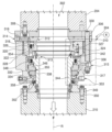
図1に示す掘削システム100は、ドリルストリング110の一端に配置されるドリルビット108を使用して地面106に試錐孔104を掘削するドリルを作動させる、様々な掘削装置を支持する支持塔ないしデリック102を含む。図に示す実施態様において、ドリルビット108は、ドリルビット108に隣接するドリルストリング110の端部に配置されるタービン112によって駆動される。典型的な態様では、泥水または他の液体または凝集性流体(agglomerate fluid)は、加圧されて中空のドリルストリング110を通って提供されてタービン112を作動させる。作動中のタービン112によって排出される流体は、掘削くずを運んで試錐孔104を通って地上に戻る。
The
ドリルストリング110は、下向きに押されるが、これはトップドライブ116に回転可能に係合される、スプラインを付けた部分またはケリー114との係合によって回転されるようにしてもよい。トップドライブは、デリック102の高さに沿って上下に移動してドリルストリングにドリルパイプを継ぎ足したり取り外したりする回転駆動装置であり、また、ケリー114を回転駆動させたり、ドリルストリングを通って泥水を提供してタービン112を作動させたりする。トップドライブ116は、図に示すような、ウインチまたはドローワークス124によって巻き上げられるケーブル122で接続されたトラベリングブロック(動滑車)118とクラウンブロック120といった、プーリーのシステムを使って昇降され得る。ドリルストリングを試錐孔104内で前進させながら、ケーブル122を解放したり戻したりするとトップドライブ116が昇降する。トップドライブ116は、ドリルストリング110を駆動させる駆動機構126を含み、また、泥水をドリルストリング110を通って提供する流体管128も含む。ウォッシュパイプシール構造体130が使用されて、ドリルストリングの一端の回転する部分とトップドライブ上のドリルストリングの駆動機構の静止部分の間で泥水が漏出しないようにシールを提供する。図に示す通り、泥水は、タンク132から提供されてもよく、そこからポンプ134が泥水を汲み上げて、トップドライブ116とポンプ134の間に接続され、かつ、作動中のトップドライブの鉛直方向の移動に従うホース136を通って、トップドライブ116に泥水を提供する。
The
掘削システム100から図解のために取り出した、トップドライブ116の一部の部分拡大図を図2に示す。この図において、泥水入口ないしグーズネック開口202が示され、これを通って、泥水が加圧されて経由するトップドライブに提供されドリルストリング110へと提供される(図1)。開口202は、増強装置のハウジング206と一体化された流体管204の端部に形成されている。トップドライブフレーム208等の静止部品と回転可能な駆動装置210の間に配置される、ドリルストリング110と係合してこれを回転させるウォッシュパイプシール130を通って流体が供給される。増強装置のハウジング206(断面を示す図6を参照してさらに詳細に後述する)は、増強装置のハウジング206に、ねじを切ったナット214によって取り付けられたピストンハウジング212を含む。ピストンハウジング212に結合して流体遮断器216があり、これは図6を参照してさらに詳細に後述する。
A partially enlarged view of a portion of
図3はウォッシュパイプシール構造体130の断面を示し、図4は拡大詳細図である。これらの図を参照すると、見ての通り、ウォッシュパイプシール構造体130は、トップドライブ116の一部である静止流体管204と、回転するドリルストリング110と回転可能に係合する回転可能な駆動装置210の間に配置される部品の集合(アセンブリ)である。このように、ウォッシュパイプシール構造体130は、トップドライブ、ウォッシュパイプ及びドリルストリングを通って延びる泥水管302に沿ってシールを提供しつつ、互いに対して回転するように構成された部分を含む。
3 shows a cross-section of the
より具体的には、ウォッシュパイプシール構造体130は、流体管204に接続された回転しないフレーム304を含む。回転しないフレーム304は、流体管204の一端に、密閉された境界面に沿って締め具308で接続された、取付プレート306を含む。拡張プレート310が、密閉された境界面に沿って取付プレート306に接続されている。拡張プレート310は、円錐形の面312を形成する裾広がりの開口を含み、これが、矢印Fで示す方向に泥水管302を通過する泥水が流れる面積を増加させる。拡張プレート310は、拡張プレート310の少なくとも一部を通って半径方向に延び、かつ、第1の回転しないシール担持体320に形成された移送経路318に緩衝流体入口314を流体接続する、緩衝流体経路316に流体接続されている緩衝流体入口314をさらに含む。
More specifically,
第1の回転しないシール担持体320は、概して中空の円筒形状であり、取付プレート306に向かい合う拡張プレート310に接して配置されて、これにより、第1の回転しないシール担持体320の内部空洞ないし孔322が、移送経路318の内部の端部ないし開口及び緩衝流体入口314と流体接続する。第1の回転しないシール担持体320は、第1の回転しないシール324をスライド可能かつ回転不可能に支持する。第1の回転しないシール324は、ばね326によって、拡張プレート310から離れる方向(図3の紙面で下向きの方向)に付勢される。ばね326は、第1の回転しないシール担持体320の一部と第1の回転しないシール324の間に配置される。第1の回転しないシール担持体320と第1の回転しないシール324において整列した構成要素を通って延びるピン327が、これら2つの部品の互いに対する回転を防ぎつつ、軸方向にかつスライド可能に係合させる。
The first
第2の回転しないシール担持体328は、分離された部品であってもよく、または図の実施態様に示す通り、第1の回転しないシール担持体320と一体化した単一の部品であってもよいが、1以上の細長い締め具330によって、拡張プレート310に向かい合う第1の回転しないシール担持体320に密閉可能に接続されるか一体化されている。第2の回転しないシール担持体328は、ピン334によってこの上に接続されこれと回転可能に係合される第2の回転しないシール332を含む。また、第2の回転しないシール担持体328は、第1の回転しないシール担持体320の孔322と流体的に組み合わせまたは接続可能に概して整列される孔336を形成する中空の円筒形状である。第2の回転しないシール担持体328に形成された孔336は、第2の回転しないシール332を含む。このようにして、第1及び第2の回転しないシール324及び332が、向かい合う関係で結合された孔322及び336の中に配置されるが、シールを付勢するばねの方向もシールそれ自体も、逆向きも可能であることが留意されるべきである。第2の回転しないシール担持体328は追加の緩衝流体入口315をさらに含み、これが、第2の回転しないシール担持体328の少なくとも一部を半径方向に通って延び、かつ、この追加の緩衝流体入口315を孔336の内側に流体接続する、緩衝流体経路317に流体接続されている。
The second
中空の管状の形状をした回転するシール担持体338は、概して円筒形の壁に囲まれている泥水管302の一区画を規定する中央の管状通路を含んでいる。回転するシール担持体338は、結合された孔322及び336の中に回転可能に配置されている。壁は、回転軸Rに対して半径方向に外向きの方向に延びるフランジ340(図4の拡大図に示す。)を含み、この軸が泥水管302を貫通して延びている。フランジ340は、軸Rに対する半径方向と軸方向の両方で完全に結合孔322/326の中に配置されている。第1の回転するシール342は、軸Rに沿う軸方向にフランジ340の片側上で、回転するシール担持体338に接続されている。図の実施態様において、第1の回転するシール342は、円筒形の壁344の一端に適合する大きさであり、フランジ340に対して半径方向に内向きに配置されている。第1の回転するシール342に隣接する壁344は、円錐形の面313を形成する裾狭まりの開口を含み、これが、矢印Fで示す方向に泥水管302を通過する泥水が流れる面積を減少させる。
The hollow tubular shaped
第2の回転するシール346は、回転するシール担持体338にスライド可能に接続され、軸Rに沿う軸方向に対して第1の回転するシール342から見てフランジ340の反対側に配置される。1以上のばね348が、第2の回転するシール346をフランジから離れる方向に付勢し、また、第1の回転するシール342も(例えば、図3の紙面において下向きに)付勢するが、このばねが作用する方向ないしシールは逆向きも可能であり、また、ばねを両方の回転するシールに適用することもできる。フランジ340と反対側の一端上では、回転するシール担持体が、取付カラー349を通して回転可能な駆動装置210に接続されて密閉可能に係合され、これが、順に、締め具350を使用して回転可能な駆動装置210に締め付けられる。二次シール352は、図の実施態様では、第1の回転しないシール担持体320に向かう方向に開いたU字断面を含む圧力シールとして具体化されているが、回転するシール担持体338の外面と第2の回転しないシール担持体328に形成された孔336の内面との間に、密閉可能に配置されまたは係合される。排出ポート353は、第2の回転しないシール担持体328を通って延びて、二次シール325に隣接する領域において、二次シール325と第2の回転しないシール332の間で孔336に流体接続される。
A second
作動中は、ウォッシュパイプシール構造体130は、泥水管302の周囲でスライドするシールの機能を提供するように構成されかつそのように動作して、泥水(または、一般的に、小砂利を含む流体ないし液体)が、泥水管302の異なる区画を含む回転する構造と回転しない構造の間に泥水管302に沿って配置される、スライドする境界面に漏出するのを防止する。
In operation,
図の実施態様において、ウォッシュパイプシール構造体130は、第1の回転しないシール324と第1の回転するシール342との間の、円形の、スライドする接触領域ないし境界面によって形成される、第1のスライドするまたはメカニカル面シール354を含む。第1のメカニカル面シール354は泥水管302に沿って配置されてシール機能を提供し、泥水管302を通過する流体が、泥水管から孔322及び336内に規定される空洞356(図4)に漏出したり逃げ込んだりするのを阻止する。第2のスライドするメカニカル面シール355は、第2の回転しないシール332と第2の回転するシール346との間の、円形の、スライドする接触領域ないし境界面によって形成される。それゆえ、孔322及び336の中に規定される空洞356は、概して密閉されて、第1のメカニカル面シール354と第2のメカニカル面シール355の間で、少なくとも部分的に孔322及び336の中に存在する。空洞356は、緩衝流体入口314と追加の緩衝流体入口315の両方を経由して外から流体的にアクセス可能である。第2の空洞358もまた、少なくとも部分的に孔322及び/または336の中に規定されて、第2のメカニカル面シール355と二次シール352の間を延びる。第2の空洞358は、排出ポート353経由で外からアクセス可能である。
In the illustrated embodiment, the
作動中は、回転するシール担持体338が第1及び第2の(または結合された)回転しないシール担持体320及び328に対して回転している間、泥水または他の流体の絶え間ない流れが圧力P1で泥水管302を通って提供される。泥水管302を流れる泥水は、裾狭まりの円錐形の面313を通過して加速し、したがって、第1のメカニカル面シール354を通過するに従いその動的圧力を減少させる。油圧オイル等の緩衝流体が緩衝流体入口314または315を通って提供され、第1チャンバ356を満たす。緩衝流体は圧力P2で提供され、これは、泥水の圧力P1と少なくとも同等であり、好ましくはそれより高い圧力であり、P1≦P2となる。このようにして、第1のメカニカル面シール354が、圧力差なしに、または、好ましくは、緩衝流体を泥水管302に向かわせその中へと移動させることになる圧力差に、暴露される。泥水の研磨性の性質を考慮すれば、緩衝流体がメカニカル面シール境界面に入ると、第1の回転しないシール及び回転するシール324及び342のスライドして接触する部分への潤滑と冷却の両方の機能を果たす。
In operation, while the
緩衝流体は、第1のメカニカル面シール354によって、また、第2のメカニカル面シール355によっても、第1の空洞の中に圧力P2で維持される。第2のメカニカル面シール355は、片側が圧力P2に暴露され、また、P3<P2となるより低い圧力または大気圧P3にも暴露される。圧力P3は、第2の空洞358に曝されるシールの側面に存在する。緩衝流体または油圧オイルは、密閉されていてもよく、または、代替的に、第2のメカニカル面シール355を通って第2の空洞358へと、制御された速度で漏出が許容されていてもよい。第2の空洞358に存在する緩衝流体は、二次シール352によって回収されて、排出開口353を通って取り除かれてもよい。緩衝流体が第2のメカニカル面シール355を通る漏出が許容または設計される速度は、緩衝流体が第1のメカニカル面シール354から吸収した熱の量に基づいて選択されてもよく、これにより、第1チャンバ356における緩衝流体の、結果として得られるないし定常状態の望ましい温度が達成され得る。第2チャンバ358の中に移動することが許容される緩衝流体は、流体の供給によって第1チャンバ356に補充され、こうして、第1チャンバ356が稼働時間(例えば、8時間)について流体で満たされるようにする。また、緩衝流体を第1チャンバ356に提供する緩衝流体タンクを大きくすることによって、より長い期間使用することもできる。
Buffer fluid is maintained in the first cavity at pressure P2 by a first
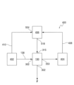
ウォッシュパイプシール130に関連する様々な流体部品の模式図を図5に示す。説明の便宜のため、既出の要素には既に使用したものと同じ参照符号を使用する。この図において、流体供給システム400は、泥水供給源402を含み、これが、例えば、ホース136(図1)を通って、泥水管302への泥水の流れを提供する。また、システム400は、緩衝流体供給源404も含み、これが、緩衝流体(例えば、油圧オイル)を含むタンクを含み得る。緩衝流体供給源404は、緩衝流体を低い圧力(例えば、圧力P3)で、供給導管408を通って圧力レギュレータまたは増強装置406に提供する。同様に、泥水供給源402は、泥水供給圧力P1で、概して静圧の導管410を通って増強装置406に泥水または少なくとも流体を提供する。増強装置406は、作動中に泥水圧力P1を使用して、緩衝流体圧力P3を緩衝流体圧力P2に自動的に制御するまたは増強させるように動作して、泥水圧力P1の変動が、緩衝流体圧力P2における対応する変動によって考慮されるようにして、上述した理由のためにP1≦P2の関係を常に維持する。
A schematic diagram of various fluidic components associated with
増強装置406の可能かつ例示的な実施態様を図6に断面で示す。増強装置406は、第1直径D1を有する泥水ピストンチャンバ502を含む。泥水ピストンチャンバ502は、泥水管302(図3)に提供される泥水の流れFに開かれこれと流体接続する泥水入口ポート504に流体接続されて、これにより、泥水ピストンチャンバ502内の流体が、泥水管302を通過する泥水流体供給の圧力P1で存在するようにする。泥水ピストンチャンバ502が底部材506に形成されており、これが図2に増強装置ハウジング206に接続されて示されている。
A possible exemplary implementation of
ピストンハウジング212は、D1よりも小さい、D2<D1である直径D2を有する緩衝流体ピストンチャンバ508を形成する。このチャンバ502及び508は、その中央線に沿って整列して互いに対して開いているので中央線Lを有する階段状のチャンバを形成している。ステム510がスライド可能かつ密閉可能にブッシング512に配置されて、中央線Lに沿ってチャンバ502及び508内に延びている。圧力の増強(P2>P1)が望ましいか、または単純な追従(P1=P2)が望ましいかによって、ステム510は、1つのプランジャ514または2つのプランジャ(即ち、プランジャ514と、点線で示す追加のプランジャ516)を含み得る。1つのプランジャ514が使用される場合は、チャンバ502からの圧力P1は、プランジャ514の片側に作用して、これにより、流体圧力P1が、等しい圧力P2をチャンバ508に存在する緩衝流体に存在するようにする(P2=P1)。増強が望ましい場合は、圧力P1は、より大きい直径D2で追加のプランジャ516の片側に作用して、これにより、第1のプランジャ514がチャンバ508に存在する緩衝流体に作用すると、D2とD1から導かれる面積の割合に依存する係数による増強が起こる。増強された緩衝流体が、ポート518によって提供される。バルブシステム520が、チャンバ508内の緩衝流体を補充する。
ウォッシュパイプシールアセンブリを作動させる方法のフローチャートを図7に示す。本方法に従えば、少なくとも1つの回転しないシール担持体が泥水管を少なくとも部分的に囲んで配置されるが、これは、掘削装置の一部として提供されてもよい。泥水管は、回転する機械部品と回転しない機械部品の全体に延びている。ウォッシュパイプシールアセンブリは、602で泥水管の少なくとも1区画を形成してもよく、604で2つのシール要素の間に規定され、かつ、回転する機械部品と回転しない機械部品の間の境界面に配置される第1のスライドするメカニカル面シールを含む。ウォッシュパイプシールアセンブリは、606で2つの追加のシール要素の間に形成される第2のメカニカル面シールをさらに含んでいてもよく、608で第1及び第2のメカニカル面シールの間のハウジングの中に空洞を規定する。第1のメカニカル面シールを越える泥水管からの流体の漏出を止めるために、610で加圧した緩衝流体が空洞に提供されてもよい。自由選択で、緩衝流体が、泥水管の中の流体の圧力に少なくとも等しい圧力で、第1の及び/または第2のメカニカル面シールの形成に加わるシール要素に潤滑を行い対流的に冷却するタイプの流体として、提供されてもよい。また、第2のメカニカル面シールを越える緩衝流体の制御された漏出も、緩衝流体の冷却機能に寄与するように提供されてもよく、その場合は、緩衝流体の補充が行われてもよい。液圧増強装置または圧力レギュレータが、612で空洞に提供される緩衝流体の圧力を自動的に調節してもよい。二次シールは、第2のメカニカル面シールを通過して流れ出る緩衝流体があれば、排出のために追加の空洞の中にさらに回収してもよい。 A flowchart of a method of operating the washpipe seal assembly is shown in FIG. According to the method, at least one non-rotating seal carrier is arranged at least partially surrounding the mud pipe, which may be provided as part of the drilling rig. Mud pipes extend throughout rotating and non-rotating machine parts. A wash pipe seal assembly may form at least one section of a mud pipe at 602 and is defined between two seal elements at 604 and at an interface between a rotating mechanical component and a non-rotating mechanical component. a first sliding mechanical face seal disposed therein; The wash pipe seal assembly may further include a second mechanical face seal formed between two additional seal elements at 606, and a second mechanical face seal formed at 608 between the first and second mechanical face seals of the housing. Define a cavity inside. A pressurized buffer fluid may be provided to the cavity at 610 to stop leakage of fluid from the mud tube beyond the first mechanical face seal. Optionally, the buffer fluid lubricates and convectively cools the sealing elements that participate in the formation of the first and/or second mechanical face seal at a pressure at least equal to the pressure of the fluid in the mud pipe. may be provided as a fluid. Controlled leakage of buffer fluid across the second mechanical face seal may also be provided to contribute to the cooling function of the buffer fluid, in which case replenishment of the buffer fluid may occur. A hydraulic booster or pressure regulator may automatically adjust the pressure of the buffer fluid provided to the cavity at 612. The secondary seal may be further withdrawn into an additional cavity for drainage if there is any buffer fluid flowing past the second mechanical face seal.
本明細書において引用する、公報、特許出願、及び特許を含む全ての文献は、参照することにより、各文献が個別にかつ具体的に示され、その全体が本明細書中に規定されているかのようにそれぞれの記載と同程度に、本明細書に組み込まれる。 All documents, including publications, patent applications, and patents, cited herein are individually and specifically indicated by reference, and are incorporated herein by reference in their entirety. are incorporated herein to the same extent as if each were written as such.
本発明を説明する文脈における(特に下記の特許請求の範囲の文脈における)1つに言及する用語(冠詞「a」、「an」及び「the」)、及び「少なくとも1つ(at least one)」並びにこれらと同様の文言の使用は、本明細書中に別段の明示があるか文脈に明らかに反しない限り、単数と複数の両方を包含すると解釈されるべきものである。1以上の項目の列挙を伴う用語「少なくとも1つ」の使用(例えば、「A及びBの少なくとも1つ」)は、本明細書中に別段の明示があるか文脈に明らかに反しない限り、列挙される項目から選択される1項目(AまたはB)または列挙される項目の2以上の任意の組合せ(A及びB)を意味する用語として解釈されるべきものである。用語「含む/有する(comprising)」、「有する(having)」、「含む(including)」及び「含む(containing)」は、本明細書中に別段の記述がない限り、例示列挙を意味する(即ち、「~を含むがこれに限定されない」を意味する)用語として解釈されるべきものである。本明細書における数値範囲の言及は、本明細書中に別段の明示がない限り、その範囲に含まれる各個別の数値にそれぞれ言及する簡便な方法として機能することを意図するにすぎず、各個別の数値は、あたかも本明細書中にそれぞれ個別に言及されているかのように、本明細書中に組み込まれる。本明細書に記載される全ての方法は、本明細書中に別段の明示があるか文脈に明らかに反しない限り、任意の適切な順序で行われ得る。本明細書中におけるいかなる例または例示を示す文言(例、「等」)の使用も、本発明をよりよく説明することを意図するにすぎず、請求項に別段の記載がない限り、本発明の範囲を限定するものではない。本明細書におけるいかなる文言も、請求項に記載されない要素を本発明の実施に必須のものとして示していると解釈されるべきではない。 Terms referring to one (the articles "a", "an" and "the") in the context of describing the invention (particularly in the context of the following claims) and "at least one"; '' and similar words are to be construed to include both the singular and the plural, unless clearly stated otherwise herein or the context clearly contradicts. The use of the term "at least one" with a listing of one or more items (e.g., "at least one of A and B") does not include the use of the term "at least one" unless explicitly stated otherwise herein or clearly contradicted by context. The term should be interpreted as meaning one item (A or B) selected from the listed items or any combination of two or more of the listed items (A and B). The terms "comprising", "having", "including" and "containing" mean an exemplary enumeration, unless stated otherwise herein. That is, it should be construed as a term meaning "including, but not limited to." References to numerical ranges herein, unless expressly stated otherwise herein, are intended to serve only as a convenient way to refer to each individual numerical value within the range, and each Each individual numerical value is incorporated herein as if each were individually mentioned herein. All methods described herein may be performed in any suitable order, unless explicitly stated otherwise herein or the context clearly contradicts. The use of any example or exemplary language (e.g., "etc.") herein is only intended to better describe the invention, and unless otherwise stated in the claims, the invention It does not limit the scope of No language in the specification should be construed as indicating any non-claimed element as essential to the practice of the invention.
本発明を実施するための本発明者らに知られている最良の形態を含む、この発明の好ましい実施態様は本明細書に記載されている。好ましい実施態様の変化形は、上述の説明を読んだ当業者に明らかとなるであろう。本発明者らは当業者がそれらの変化形を適切に採用することを期待しており、また、本発明者らは本発明が、本明細書中に具体的に記載した通りのもの以外にも実施されるべきことを意図している。したがって、この発明は、適用される法が許容する限りにおいて、本明細書に添付する特許請求の範囲に記載される主題のあらゆる改変物及び均等物を含む。さらに、あり得る変化形における上述の要素の任意の組合せも、本明細書中に別段の明示があるか文脈に明らかに反しない限り、本発明に包含される。 Preferred embodiments of this invention are described herein, including the best mode known to the inventors for carrying out the invention. Variations on the preferred embodiment will be apparent to those skilled in the art upon reading the above description. The inventors expect that those skilled in the art will appropriately adapt such variations, and the inventors expect that the invention may be implemented in ways other than as specifically described herein. is also intended to be implemented. Accordingly, this invention includes all modifications and equivalents of the subject matter recited in the claims appended hereto as permitted by applicable law. Furthermore, any combination of the above-mentioned elements in possible variations is also encompassed by the invention, unless stated otherwise herein or clearly contradicted by context.
Claims (11)
前記回転しない機械部品に接続された回転しないフレームを有し、前記回転しないフレームが回転しないシール担持体を含み、前記回転しないシール担持体が内部空洞を形成する概して中空の円筒形状であり、
前記回転しないシール担持体に接続された第1の回転しないシールを有し、
前記回転しないシール担持体に接続された第2の回転しないシールを有し、前記第1及び第2の回転しないシールが前記内部空洞に互いに対して空間を空けて配置され、
少なくとも部分的に前記内部空洞内に回転可能に配置される回転可能なシール担持体を有し、
前記回転可能なシール担持体に接続され、かつ、前記第1の回転しないシールに隣接して配置される第1の回転するシールを有し、
前記回転可能なシール担持体に接続され、かつ、前記第2の回転しないシールに隣接して配置される第2の回転するシールを有する、前記ウォッシュパイプシール構造体において、
作動中は、前記第1の回転するシールが、前記第1の回転しないシールに接して、前記流体管を密閉するように構成されている第1のスライドするメカニカルシールを規定し、及び、
作動中は、前記第2の回転するシールが前記第2の回転しないシールに接して、前記内部空洞の第1の部分を密閉するように構成されている第2のスライドするメカニカルシールを規定し、前記内部空洞の前記第1の部分が、前記回転しないシール担持体と前記回転可能なシール担持体との間にあり、かつ、前記流体管から分離されていて、かつ、前記流体管と並んでおり、かつ、前記内部空洞の前記第1の部分が、前記第2のスライドするメカニカルシールから前記第1のスライドするメカニカルシールの方に延びており、前記ウォッシュパイプシール構造体が、
前記回転しないシール担持体と前記第1の回転しないシールの間に配置される少なくとも1つの第1のばねをさらに有し、前記第1の回転しないシールが前記回転しないシール担持体上にスライド可能に配置され、かつ、前記少なくとも1つの第1のばねが前記第1の回転しないシールを前記第1の回転するシールに向かう方向に付勢し、
前記回転可能なシール担持体と前記第2の回転するシールの間に配置される少なくとも1つの第2のばねをさらに有し、前記第2の回転するシールが前記回転可能なシール担持体上にスライド可能に配置され、かつ、前記少なくとも1つの第2のばねが前記第2の回転するシールを前記第2の回転しないシールに向かう方向に付勢する、
ウォッシュパイプシール構造体。 A wash pipe seal structure disposed between a non-rotating mechanical component and a rotating mechanical component and along a fluid conduit extending throughout the rotating and non-rotating mechanical component, the The wash pipe seal structure is
a non-rotating frame connected to the non-rotating mechanical component, the non-rotating frame including a non-rotating seal carrier, the non-rotating seal carrier having a generally hollow cylindrical shape defining an internal cavity;
a first non-rotating seal connected to the non-rotating seal carrier;
a second non-rotating seal connected to the non-rotating seal carrier, the first and second non-rotating seals being spaced apart from each other in the internal cavity;
a rotatable seal carrier rotatably disposed at least partially within the internal cavity;
a first rotating seal connected to the rotatable seal carrier and positioned adjacent to the first non-rotating seal;
The wash pipe seal structure has a second rotating seal connected to the rotatable seal carrier and positioned adjacent to the second non-rotating seal;
In operation, the first rotating seal abuts the first non-rotating seal and defines a first sliding mechanical seal configured to seal the fluid conduit;
a second sliding mechanical seal configured such that, in operation, the second rotating seal contacts the second non-rotating seal to seal a first portion of the internal cavity; the first portion of the internal cavity is between the non-rotating seal carrier and the rotatable seal carrier and is separated from the fluid conduit; the first portion of the internal cavity extending from the second sliding mechanical seal toward the first sliding mechanical seal; but,
further comprising at least one first spring disposed between the non-rotating seal carrier and the first non-rotating seal, the first non-rotating seal being slidable onto the non-rotating seal carrier; and the at least one first spring biases the first non-rotating seal in a direction toward the first rotating seal;
further comprising at least one second spring disposed between the rotatable seal carrier and the second rotating seal, the second rotating seal being mounted on the rotatable seal carrier; the at least one second spring biasing the second rotating seal in a direction toward the second non-rotating seal;
Washpipe seal structure.
前記トップドライブの回転しない機械部品に接続された回転しないフレームを有し、前記回転しないフレームが回転しないシール担持体を含み、前記回転しないシール担持体が内部空洞を形成する概して中空の円筒形状であり、
前記回転しないシール担持体に接続された第1の回転しないシールと、前記回転しないシール担持体に接続された第2の回転しないシールを有し、前記第1及び第2の回転しないシールが前記内部空洞内に互いに対して空間を空けて配置され、
少なくとも部分的に前記内部空洞内に回転可能に配置される回転可能なシール担持体を有し、
前記回転可能なシール担持体に接続されて前記第1の回転しないシールに隣接して配置される第1の回転するシールと、前記回転可能なシール担持体に接続されて前記第2の回転しないシールに隣接して配置される第2の回転するシールを有する、前記ウォッシュパイプシール構造体であって、
作動中は、前記第1の回転するシールが前記第1の回転しないシールに接して、前記泥水管を密閉するように構成されている第1のスライドするメカニカルシールを規定し、
前記第2の回転するシールが前記第2の回転しないシールに接して、前記内部空洞の第1の部分を密閉するように構成されている第2のスライドするメカニカルシールを規定し、前記内部空洞の前記第1の部分が、前記回転しないシール担持体と前記回転可能なシール担持体との間にあり、かつ、前記泥水管から分離されていて、かつ、前記泥水管と並んでおり、かつ、前記内部空洞の前記第1の部分が、前記第2のスライドするメカニカルシールから前記第1のスライドするメカニカルシールの方に延びており、及び、
緩衝流体が、前記泥水管内の泥水の圧力と少なくとも同等以上の圧力で提供され、前記緩衝流体が、前記内部空洞の前記第1の部分に提供され、前記ウォッシュパイプシール構造体が、
前記回転しないシール担持体と前記第1の回転しないシールの間に配置される少なくとも1つの第1のばねをさらに有し、前記第1の回転しないシールが、前記回転しないシール担持体上にスライド可能に配置され、かつ、前記少なくとも1つの第1のばねが、前記第1の回転しないシールを前記第1の回転するシールに向かう方向に付勢し、
前記回転可能なシール担持体と前記第2の回転するシールの間に配置される少なくとも1つの第2のばねをさらに有し、前記第2の回転するシールが、前記回転可能なシール担持体上にスライド可能に配置され、かつ、前記少なくとも1つの第2のばねが、前記第2の回転するシールを前記第2の回転しないシールに向かう方向に付勢する、
ウォッシュパイプシール構造体。 A washpipe seal structure for use with a mud pipe in a drilling operation, the mud pipe extending between a top drive and a drill string, the wash pipe seal structure comprising:
a non-rotating frame connected to a non-rotating mechanical component of the top drive, the non-rotating frame including a non-rotating seal carrier, the non-rotating seal carrier having a generally hollow cylindrical shape forming an internal cavity; can be,
a first non-rotating seal connected to the non-rotating seal carrier and a second non-rotating seal connected to the non-rotating seal carrier, the first and second non-rotating seals being connected to the non-rotating seal carrier; spaced from each other within the internal cavity;
a rotatable seal carrier rotatably disposed at least partially within the internal cavity;
a first rotating seal connected to the rotatable seal carrier and positioned adjacent the first non-rotating seal; and a first rotating seal connected to the rotatable seal carrier and positioned adjacent the first non-rotating seal. The wash pipe seal structure having a second rotating seal disposed adjacent the seal,
defining a first sliding mechanical seal configured such that, in operation, the first rotating seal abuts the first non-rotating seal to seal the mud pipe;
defining a second sliding mechanical seal, wherein the second rotating seal is configured to contact the second non-rotating seal to seal a first portion of the internal cavity; the first portion of the internal cavity is between the non-rotatable seal carrier and the rotatable seal carrier and is separated from and juxtaposed with the mud pipe; and the first portion of the internal cavity extends from the second sliding mechanical seal toward the first sliding mechanical seal, and
a buffer fluid is provided at a pressure at least equal to or greater than the pressure of mud water in the mud pipe, the buffer fluid is provided in the first portion of the internal cavity, and the wash pipe seal structure comprises:
further comprising at least one first spring disposed between the non-rotating seal carrier and the first non-rotating seal, the first non-rotating seal sliding onto the non-rotating seal carrier; the at least one first spring biasing the first non-rotating seal in a direction toward the first rotating seal;
further comprising at least one second spring disposed between the rotatable seal carrier and the second rotating seal, the second rotating seal being mounted on the rotatable seal carrier. the at least one second spring biasing the second rotating seal in a direction toward the second non-rotating seal;
Washpipe seal structure.
Priority Applications (1)
| Application Number | Priority Date | Filing Date | Title |
|---|---|---|---|
| JP2023217662A JP7676525B2 (en) | 2019-09-10 | 2023-12-25 | Wash Pipe System and Method |
Applications Claiming Priority (3)
| Application Number | Priority Date | Filing Date | Title |
|---|---|---|---|
| US201962898223P | 2019-09-10 | 2019-09-10 | |
| US62/898,223 | 2019-09-10 | ||
| PCT/US2020/049904 WO2021050520A1 (en) | 2019-09-10 | 2020-09-09 | Washpipe system and method |
Related Child Applications (1)
| Application Number | Title | Priority Date | Filing Date |
|---|---|---|---|
| JP2023217662A Division JP7676525B2 (en) | 2019-09-10 | 2023-12-25 | Wash Pipe System and Method |
Publications (4)
| Publication Number | Publication Date |
|---|---|
| JP2022548562A JP2022548562A (en) | 2022-11-21 |
| JPWO2021050520A5 JPWO2021050520A5 (en) | 2023-06-27 |
| JP2022548562A5 JP2022548562A5 (en) | 2023-06-27 |
| JP7411069B2 true JP7411069B2 (en) | 2024-01-10 |
Family
ID=74850883
Family Applications (2)
| Application Number | Title | Priority Date | Filing Date |
|---|---|---|---|
| JP2022515796A Active JP7411069B2 (en) | 2019-09-10 | 2020-09-09 | Washpipe system and method |
| JP2023217662A Active JP7676525B2 (en) | 2019-09-10 | 2023-12-25 | Wash Pipe System and Method |
Family Applications After (1)
| Application Number | Title | Priority Date | Filing Date |
|---|---|---|---|
| JP2023217662A Active JP7676525B2 (en) | 2019-09-10 | 2023-12-25 | Wash Pipe System and Method |
Country Status (7)
| Country | Link |
|---|---|
| US (1) | US11414939B2 (en) |
| EP (1) | EP4028632A4 (en) |
| JP (2) | JP7411069B2 (en) |
| KR (1) | KR102660561B1 (en) |
| CA (1) | CA3150351A1 (en) |
| MX (2) | MX2022002915A (en) |
| WO (1) | WO2021050520A1 (en) |
Families Citing this family (1)
| Publication number | Priority date | Publication date | Assignee | Title |
|---|---|---|---|---|
| GB2643617A (en) * | 2023-03-09 | 2026-02-25 | Forum Us Inc | Washpipe assembly |
Citations (4)
| Publication number | Priority date | Publication date | Assignee | Title |
|---|---|---|---|---|
| JP2918874B1 (en) | 1998-02-18 | 1999-07-12 | 日本ピラー工業株式会社 | Mechanical seal and rotary joint for slurry fluid |
| JP2002005365A (en) | 2000-06-19 | 2002-01-09 | Nippon Pillar Packing Co Ltd | Multiple flow passage type rotary joint |
| JP2009127738A (en) | 2007-11-22 | 2009-06-11 | Nippon Pillar Packing Co Ltd | Rotary joint |
| JP2013036489A (en) | 2011-08-04 | 2013-02-21 | Nippon Pillar Packing Co Ltd | Multiple flow passage type rotary joint |
Family Cites Families (19)
| Publication number | Priority date | Publication date | Assignee | Title |
|---|---|---|---|---|
| JPS57178092A (en) * | 1981-04-25 | 1982-11-02 | Okada Sakuganki Kk | Oil pressure type rock drilling machine |
| JP3483015B2 (en) * | 1995-10-16 | 2004-01-06 | 古河機械金属株式会社 | Hydraulic shock absorber shock absorber |
| US6007105A (en) | 1997-02-07 | 1999-12-28 | Kalsi Engineering, Inc. | Swivel seal assembly |
| JP3824112B2 (en) * | 1997-07-18 | 2006-09-20 | 古河機械金属株式会社 | Shock absorber of hydraulic striking device |
| US6467557B1 (en) * | 1998-12-18 | 2002-10-22 | Western Well Tool, Inc. | Long reach rotary drilling assembly |
| US6554016B2 (en) | 2000-12-12 | 2003-04-29 | Northland Energy Corporation | Rotating blowout preventer with independent cooling circuits and thrust bearing |
| GB0412612D0 (en) * | 2004-06-07 | 2004-07-07 | Aesseal Plc | Mechanical seal with floating face |
| US7343968B2 (en) * | 2004-08-27 | 2008-03-18 | Deublin Company | Washpipe seal assembly |
| CA2585669A1 (en) | 2006-04-27 | 2007-10-27 | National-Oilwell, L.P. | Apparatus for interconnecting and sealing between fixed and rotating conduits and method of installing same |
| US7487848B2 (en) | 2006-04-28 | 2009-02-10 | Varco I/P, Inc. | Multi-seal for top drive shaft |
| US8702106B2 (en) | 2006-07-20 | 2014-04-22 | Hydril Usa Manufacturing Llc | Pressure energized radial seal |
| ITTO20130694A1 (en) * | 2013-08-14 | 2015-02-15 | Umbra Meccanotecnica | WASHPIPE JOINT FOR A PETROLIFY DRILLING SYSTEM |
| US9540898B2 (en) | 2014-06-26 | 2017-01-10 | Sunstone Technologies, Llc | Annular drilling device |
| DE102014221000B3 (en) * | 2014-10-16 | 2016-01-21 | Eagleburgmann Germany Gmbh & Co. Kg | Pre-assembled replacement insert of a drilling fluid device |
| WO2017110793A1 (en) * | 2015-12-24 | 2017-06-29 | 古河ロックドリル株式会社 | Hydraulic hammering device |
| WO2018226530A1 (en) | 2017-06-07 | 2018-12-13 | Deublin Company | Fluid coupling assembly |
| US10538978B1 (en) | 2017-07-21 | 2020-01-21 | Clark Seals, Ltd. | Washpipe seal assembly |
| CN111201397B (en) * | 2017-10-09 | 2022-04-29 | 杜博林公司 | Multi-channel rotary joint |
| CN110608002B (en) | 2019-09-20 | 2022-06-21 | 四川昆仑石油设备制造有限公司 | Washing pipe assembly |
-
2020
- 2020-09-09 WO PCT/US2020/049904 patent/WO2021050520A1/en not_active Ceased
- 2020-09-09 JP JP2022515796A patent/JP7411069B2/en active Active
- 2020-09-09 KR KR1020227011336A patent/KR102660561B1/en active Active
- 2020-09-09 CA CA3150351A patent/CA3150351A1/en active Pending
- 2020-09-09 EP EP20862767.9A patent/EP4028632A4/en active Pending
- 2020-09-09 MX MX2022002915A patent/MX2022002915A/en unknown
- 2020-09-09 US US17/015,716 patent/US11414939B2/en active Active
-
2022
- 2022-03-09 MX MX2023009204A patent/MX2023009204A/en unknown
-
2023
- 2023-12-25 JP JP2023217662A patent/JP7676525B2/en active Active
Patent Citations (4)
| Publication number | Priority date | Publication date | Assignee | Title |
|---|---|---|---|---|
| JP2918874B1 (en) | 1998-02-18 | 1999-07-12 | 日本ピラー工業株式会社 | Mechanical seal and rotary joint for slurry fluid |
| JP2002005365A (en) | 2000-06-19 | 2002-01-09 | Nippon Pillar Packing Co Ltd | Multiple flow passage type rotary joint |
| JP2009127738A (en) | 2007-11-22 | 2009-06-11 | Nippon Pillar Packing Co Ltd | Rotary joint |
| JP2013036489A (en) | 2011-08-04 | 2013-02-21 | Nippon Pillar Packing Co Ltd | Multiple flow passage type rotary joint |
Also Published As
| Publication number | Publication date |
|---|---|
| WO2021050520A1 (en) | 2021-03-18 |
| CA3150351A1 (en) | 2021-03-18 |
| MX2022002915A (en) | 2022-06-09 |
| KR20220055487A (en) | 2022-05-03 |
| JP7676525B2 (en) | 2025-05-14 |
| JP2022548562A (en) | 2022-11-21 |
| EP4028632A1 (en) | 2022-07-20 |
| KR102660561B1 (en) | 2024-04-24 |
| EP4028632A4 (en) | 2023-10-11 |
| MX2023009204A (en) | 2023-08-21 |
| US11414939B2 (en) | 2022-08-16 |
| BR112022004468A2 (en) | 2022-07-19 |
| US20210071487A1 (en) | 2021-03-11 |
| JP2024038075A (en) | 2024-03-19 |
Similar Documents
| Publication | Publication Date | Title |
|---|---|---|
| US4143881A (en) | Lubricant cooled rotary drill head seal | |
| USRE38249E1 (en) | Rotating blowout preventer and method | |
| US6732804B2 (en) | Dynamic mudcap drilling and well control system | |
| US4143880A (en) | Reverse pressure activated rotary drill head seal | |
| RU2405904C2 (en) | Drilling assembly for well (versions) and support mechanism and turbine power plant for drilling assembly | |
| US4529210A (en) | Drilling media injection for rotating blowout preventors | |
| US3752507A (en) | Swivel | |
| US6732819B2 (en) | Mudsaver valve with retrievable inner sleeve | |
| US6896048B2 (en) | Rotary support table | |
| RU2561136C2 (en) | System of pressure compensation for bearing assembly with oil seal of bottomhole motor | |
| CA2845547C (en) | Bearing assembly for a vertical turbine pump | |
| JP7676525B2 (en) | Wash Pipe System and Method | |
| US12055014B2 (en) | Sealing system for downhole tool | |
| US20200182006A1 (en) | Rotating Control Device with Mechanical Seal | |
| CN112177551B (en) | Double-seal-structure pipe flushing assembly, pipe flushing device, lubricating system and lubricating process | |
| US11136848B2 (en) | Rotating control device with cooling mandrel | |
| US10156095B1 (en) | Top drive and power swivel with high pressure seals and automatic refilling lubrication reservoir | |
| US20100051290A1 (en) | Pressure Actuated Piston Type Casing Fill-up Valve and Methods of Use Thereof | |
| US20100101797A1 (en) | Lubricating washpipe system and method | |
| US4328873A (en) | Automatic depth compensating system for drill bit lubrication | |
| BR112022004468B1 (en) | WASHERPIPE SEALING ARRANGEMENT, AND WASHERPIPE SEALING ARRANGEMENT FOR USE WITH A MUD PIPE IN A DRILLING OPERATION | |
| US20210254712A1 (en) | Lubrication system for a piston pump | |
| RU2856158C1 (en) | Continuous circulation sub | |
| US11661802B1 (en) | Cross BOP swivel joint for string rotation during well control events | |
| WO2025240812A1 (en) | Rotating control device rotary seal |
Legal Events
| Date | Code | Title | Description |
|---|---|---|---|
| A521 | Request for written amendment filed |
Free format text: JAPANESE INTERMEDIATE CODE: A523 Effective date: 20230619 |
|
| A621 | Written request for application examination |
Free format text: JAPANESE INTERMEDIATE CODE: A621 Effective date: 20230619 |
|
| A871 | Explanation of circumstances concerning accelerated examination |
Free format text: JAPANESE INTERMEDIATE CODE: A871 Effective date: 20230619 |
|
| A131 | Notification of reasons for refusal |
Free format text: JAPANESE INTERMEDIATE CODE: A131 Effective date: 20230815 |
|
| A521 | Request for written amendment filed |
Free format text: JAPANESE INTERMEDIATE CODE: A523 Effective date: 20231114 |
|
| TRDD | Decision of grant or rejection written | ||
| A01 | Written decision to grant a patent or to grant a registration (utility model) |
Free format text: JAPANESE INTERMEDIATE CODE: A01 Effective date: 20231128 |
|
| A61 | First payment of annual fees (during grant procedure) |
Free format text: JAPANESE INTERMEDIATE CODE: A61 Effective date: 20231222 |
|
| R150 | Certificate of patent or registration of utility model |
Ref document number: 7411069 Country of ref document: JP Free format text: JAPANESE INTERMEDIATE CODE: R150 |