JP7407790B2 - Ultrasound system with artificial neural network for guided liver imaging - Google Patents
Ultrasound system with artificial neural network for guided liver imaging Download PDFInfo
- Publication number
- JP7407790B2 JP7407790B2 JP2021503763A JP2021503763A JP7407790B2 JP 7407790 B2 JP7407790 B2 JP 7407790B2 JP 2021503763 A JP2021503763 A JP 2021503763A JP 2021503763 A JP2021503763 A JP 2021503763A JP 7407790 B2 JP7407790 B2 JP 7407790B2
- Authority
- JP
- Japan
- Prior art keywords
- image
- ultrasound
- interest
- region
- neural network
- Prior art date
- Legal status (The legal status is an assumption and is not a legal conclusion. Google has not performed a legal analysis and makes no representation as to the accuracy of the status listed.)
- Active
Links
- 238000002604 ultrasonography Methods 0.000 title claims description 104
- 210000004185 liver Anatomy 0.000 title claims description 66
- 238000013528 artificial neural network Methods 0.000 title claims description 61
- 238000003384 imaging method Methods 0.000 title claims description 26
- 238000000034 method Methods 0.000 claims description 94
- 210000001519 tissue Anatomy 0.000 claims description 60
- 230000011218 segmentation Effects 0.000 claims description 50
- 210000003734 kidney Anatomy 0.000 claims description 32
- 238000012285 ultrasound imaging Methods 0.000 claims description 24
- 239000000523 sample Substances 0.000 claims description 21
- 238000013527 convolutional neural network Methods 0.000 claims description 18
- 210000005084 renal tissue Anatomy 0.000 claims description 14
- 210000005228 liver tissue Anatomy 0.000 claims description 13
- 230000004044 response Effects 0.000 claims description 12
- 230000009467 reduction Effects 0.000 claims description 6
- 238000012360 testing method Methods 0.000 claims description 6
- 238000002059 diagnostic imaging Methods 0.000 claims description 4
- 230000010339 dilation Effects 0.000 claims description 4
- 238000007689 inspection Methods 0.000 claims 1
- 230000008569 process Effects 0.000 description 38
- 238000011002 quantification Methods 0.000 description 33
- 238000012549 training Methods 0.000 description 30
- 238000003709 image segmentation Methods 0.000 description 17
- 238000005259 measurement Methods 0.000 description 17
- 238000012545 processing Methods 0.000 description 16
- 238000001514 detection method Methods 0.000 description 14
- 230000006870 function Effects 0.000 description 14
- 238000010801 machine learning Methods 0.000 description 12
- 238000010586 diagram Methods 0.000 description 11
- 238000011176 pooling Methods 0.000 description 8
- 239000013598 vector Substances 0.000 description 7
- 230000005540 biological transmission Effects 0.000 description 6
- 210000004204 blood vessel Anatomy 0.000 description 6
- 238000004364 calculation method Methods 0.000 description 6
- 210000000056 organ Anatomy 0.000 description 6
- 230000004913 activation Effects 0.000 description 5
- 238000003491 array Methods 0.000 description 5
- 208000008338 non-alcoholic fatty liver disease Diseases 0.000 description 5
- 230000008901 benefit Effects 0.000 description 4
- 238000002592 echocardiography Methods 0.000 description 4
- 208000010706 fatty liver disease Diseases 0.000 description 4
- 230000003902 lesion Effects 0.000 description 4
- 238000000926 separation method Methods 0.000 description 4
- 230000000007 visual effect Effects 0.000 description 4
- 208000004930 Fatty Liver Diseases 0.000 description 3
- 206010019708 Hepatic steatosis Diseases 0.000 description 3
- 230000003213 activating effect Effects 0.000 description 3
- 238000004422 calculation algorithm Methods 0.000 description 3
- 238000013145 classification model Methods 0.000 description 3
- 230000001419 dependent effect Effects 0.000 description 3
- 230000001965 increasing effect Effects 0.000 description 3
- 230000007774 longterm Effects 0.000 description 3
- 210000004072 lung Anatomy 0.000 description 3
- 231100000240 steatosis hepatitis Toxicity 0.000 description 3
- 238000010200 validation analysis Methods 0.000 description 3
- 238000007792 addition Methods 0.000 description 2
- 210000003484 anatomy Anatomy 0.000 description 2
- 238000013459 approach Methods 0.000 description 2
- 239000000090 biomarker Substances 0.000 description 2
- 210000000481 breast Anatomy 0.000 description 2
- 238000006243 chemical reaction Methods 0.000 description 2
- 208000019425 cirrhosis of liver Diseases 0.000 description 2
- 238000002591 computed tomography Methods 0.000 description 2
- 238000005516 engineering process Methods 0.000 description 2
- 230000002452 interceptive effect Effects 0.000 description 2
- 230000003601 intercostal effect Effects 0.000 description 2
- 210000000231 kidney cortex Anatomy 0.000 description 2
- 208000019423 liver disease Diseases 0.000 description 2
- 206010053219 non-alcoholic steatohepatitis Diseases 0.000 description 2
- 238000012805 post-processing Methods 0.000 description 2
- 230000008707 rearrangement Effects 0.000 description 2
- 238000012216 screening Methods 0.000 description 2
- 238000007619 statistical method Methods 0.000 description 2
- 206010016654 Fibrosis Diseases 0.000 description 1
- 244000068988 Glycine max Species 0.000 description 1
- 241000699670 Mus sp. Species 0.000 description 1
- 208000008589 Obesity Diseases 0.000 description 1
- 210000001015 abdomen Anatomy 0.000 description 1
- 230000009471 action Effects 0.000 description 1
- 238000004458 analytical method Methods 0.000 description 1
- 230000003139 buffering effect Effects 0.000 description 1
- 230000007882 cirrhosis Effects 0.000 description 1
- 238000007635 classification algorithm Methods 0.000 description 1
- 238000004891 communication Methods 0.000 description 1
- 230000006835 compression Effects 0.000 description 1
- 238000007906 compression Methods 0.000 description 1
- 238000012790 confirmation Methods 0.000 description 1
- 230000008602 contraction Effects 0.000 description 1
- 238000003066 decision tree Methods 0.000 description 1
- 238000012217 deletion Methods 0.000 description 1
- 230000037430 deletion Effects 0.000 description 1
- 206010012601 diabetes mellitus Diseases 0.000 description 1
- 238000003745 diagnosis Methods 0.000 description 1
- 201000010099 disease Diseases 0.000 description 1
- 208000037265 diseases, disorders, signs and symptoms Diseases 0.000 description 1
- 238000003708 edge detection Methods 0.000 description 1
- 230000000694 effects Effects 0.000 description 1
- 238000011156 evaluation Methods 0.000 description 1
- 230000005284 excitation Effects 0.000 description 1
- 238000001914 filtration Methods 0.000 description 1
- 238000005194 fractionation Methods 0.000 description 1
- PCHJSUWPFVWCPO-UHFFFAOYSA-N gold Chemical compound [Au] PCHJSUWPFVWCPO-UHFFFAOYSA-N 0.000 description 1
- 210000005003 heart tissue Anatomy 0.000 description 1
- 230000002440 hepatic effect Effects 0.000 description 1
- 230000006872 improvement Effects 0.000 description 1
- 230000001939 inductive effect Effects 0.000 description 1
- 230000008595 infiltration Effects 0.000 description 1
- 238000001764 infiltration Methods 0.000 description 1
- 230000000977 initiatory effect Effects 0.000 description 1
- 238000002372 labelling Methods 0.000 description 1
- 238000012317 liver biopsy Methods 0.000 description 1
- 201000007270 liver cancer Diseases 0.000 description 1
- 239000003550 marker Substances 0.000 description 1
- 239000000463 material Substances 0.000 description 1
- 239000000203 mixture Substances 0.000 description 1
- 238000012986 modification Methods 0.000 description 1
- 230000004048 modification Effects 0.000 description 1
- 230000001537 neural effect Effects 0.000 description 1
- 210000002569 neuron Anatomy 0.000 description 1
- 238000010606 normalization Methods 0.000 description 1
- 235000020824 obesity Nutrition 0.000 description 1
- 230000003287 optical effect Effects 0.000 description 1
- 238000005457 optimization Methods 0.000 description 1
- 210000001672 ovary Anatomy 0.000 description 1
- 238000002600 positron emission tomography Methods 0.000 description 1
- 238000007781 pre-processing Methods 0.000 description 1
- 230000000644 propagated effect Effects 0.000 description 1
- 238000009877 rendering Methods 0.000 description 1
- 238000012552 review Methods 0.000 description 1
- 230000000630 rising effect Effects 0.000 description 1
- 238000005070 sampling Methods 0.000 description 1
- 230000035807 sensation Effects 0.000 description 1
- 239000010454 slate Substances 0.000 description 1
- 239000007787 solid Substances 0.000 description 1
- 210000000952 spleen Anatomy 0.000 description 1
- 238000012706 support-vector machine Methods 0.000 description 1
- 230000009897 systematic effect Effects 0.000 description 1
- 210000001550 testis Anatomy 0.000 description 1
- 210000001685 thyroid gland Anatomy 0.000 description 1
- 230000001960 triggered effect Effects 0.000 description 1
- 210000004291 uterus Anatomy 0.000 description 1
- 230000002792 vascular Effects 0.000 description 1
- XLYOFNOQVPJJNP-UHFFFAOYSA-N water Substances O XLYOFNOQVPJJNP-UHFFFAOYSA-N 0.000 description 1
Images


Classifications
-
- A—HUMAN NECESSITIES
- A61—MEDICAL OR VETERINARY SCIENCE; HYGIENE
- A61B—DIAGNOSIS; SURGERY; IDENTIFICATION
- A61B8/00—Diagnosis using ultrasonic, sonic or infrasonic waves
- A61B8/08—Detecting organic movements or changes, e.g. tumours, cysts, swellings
- A61B8/0833—Detecting organic movements or changes, e.g. tumours, cysts, swellings involving detecting or locating foreign bodies or organic structures
- A61B8/085—Detecting organic movements or changes, e.g. tumours, cysts, swellings involving detecting or locating foreign bodies or organic structures for locating body or organic structures, e.g. tumours, calculi, blood vessels, nodules
-
- A—HUMAN NECESSITIES
- A61—MEDICAL OR VETERINARY SCIENCE; HYGIENE
- A61B—DIAGNOSIS; SURGERY; IDENTIFICATION
- A61B8/00—Diagnosis using ultrasonic, sonic or infrasonic waves
- A61B8/13—Tomography
- A61B8/14—Echo-tomography
-
- A—HUMAN NECESSITIES
- A61—MEDICAL OR VETERINARY SCIENCE; HYGIENE
- A61B—DIAGNOSIS; SURGERY; IDENTIFICATION
- A61B8/00—Diagnosis using ultrasonic, sonic or infrasonic waves
- A61B8/46—Ultrasonic, sonic or infrasonic diagnostic devices with special arrangements for interfacing with the operator or the patient
- A61B8/461—Displaying means of special interest
- A61B8/463—Displaying means of special interest characterised by displaying multiple images or images and diagnostic data on one display
-
- A—HUMAN NECESSITIES
- A61—MEDICAL OR VETERINARY SCIENCE; HYGIENE
- A61B—DIAGNOSIS; SURGERY; IDENTIFICATION
- A61B8/00—Diagnosis using ultrasonic, sonic or infrasonic waves
- A61B8/46—Ultrasonic, sonic or infrasonic diagnostic devices with special arrangements for interfacing with the operator or the patient
- A61B8/467—Ultrasonic, sonic or infrasonic diagnostic devices with special arrangements for interfacing with the operator or the patient characterised by special input means
- A61B8/469—Ultrasonic, sonic or infrasonic diagnostic devices with special arrangements for interfacing with the operator or the patient characterised by special input means for selection of a region of interest
-
- A—HUMAN NECESSITIES
- A61—MEDICAL OR VETERINARY SCIENCE; HYGIENE
- A61B—DIAGNOSIS; SURGERY; IDENTIFICATION
- A61B8/00—Diagnosis using ultrasonic, sonic or infrasonic waves
- A61B8/52—Devices using data or image processing specially adapted for diagnosis using ultrasonic, sonic or infrasonic waves
- A61B8/5215—Devices using data or image processing specially adapted for diagnosis using ultrasonic, sonic or infrasonic waves involving processing of medical diagnostic data
- A61B8/5223—Devices using data or image processing specially adapted for diagnosis using ultrasonic, sonic or infrasonic waves involving processing of medical diagnostic data for extracting a diagnostic or physiological parameter from medical diagnostic data
-
- G—PHYSICS
- G06—COMPUTING; CALCULATING OR COUNTING
- G06N—COMPUTING ARRANGEMENTS BASED ON SPECIFIC COMPUTATIONAL MODELS
- G06N3/00—Computing arrangements based on biological models
- G06N3/02—Neural networks
- G06N3/04—Architecture, e.g. interconnection topology
-
- G—PHYSICS
- G06—COMPUTING; CALCULATING OR COUNTING
- G06N—COMPUTING ARRANGEMENTS BASED ON SPECIFIC COMPUTATIONAL MODELS
- G06N3/00—Computing arrangements based on biological models
- G06N3/02—Neural networks
- G06N3/08—Learning methods
-
- G—PHYSICS
- G06—COMPUTING; CALCULATING OR COUNTING
- G06T—IMAGE DATA PROCESSING OR GENERATION, IN GENERAL
- G06T7/00—Image analysis
- G06T7/10—Segmentation; Edge detection
-
- G—PHYSICS
- G16—INFORMATION AND COMMUNICATION TECHNOLOGY [ICT] SPECIALLY ADAPTED FOR SPECIFIC APPLICATION FIELDS
- G16H—HEALTHCARE INFORMATICS, i.e. INFORMATION AND COMMUNICATION TECHNOLOGY [ICT] SPECIALLY ADAPTED FOR THE HANDLING OR PROCESSING OF MEDICAL OR HEALTHCARE DATA
- G16H30/00—ICT specially adapted for the handling or processing of medical images
- G16H30/40—ICT specially adapted for the handling or processing of medical images for processing medical images, e.g. editing
-
- G—PHYSICS
- G16—INFORMATION AND COMMUNICATION TECHNOLOGY [ICT] SPECIALLY ADAPTED FOR SPECIFIC APPLICATION FIELDS
- G16H—HEALTHCARE INFORMATICS, i.e. INFORMATION AND COMMUNICATION TECHNOLOGY [ICT] SPECIALLY ADAPTED FOR THE HANDLING OR PROCESSING OF MEDICAL OR HEALTHCARE DATA
- G16H50/00—ICT specially adapted for medical diagnosis, medical simulation or medical data mining; ICT specially adapted for detecting, monitoring or modelling epidemics or pandemics
- G16H50/20—ICT specially adapted for medical diagnosis, medical simulation or medical data mining; ICT specially adapted for detecting, monitoring or modelling epidemics or pandemics for computer-aided diagnosis, e.g. based on medical expert systems
-
- G—PHYSICS
- G16—INFORMATION AND COMMUNICATION TECHNOLOGY [ICT] SPECIALLY ADAPTED FOR SPECIFIC APPLICATION FIELDS
- G16H—HEALTHCARE INFORMATICS, i.e. INFORMATION AND COMMUNICATION TECHNOLOGY [ICT] SPECIALLY ADAPTED FOR THE HANDLING OR PROCESSING OF MEDICAL OR HEALTHCARE DATA
- G16H50/00—ICT specially adapted for medical diagnosis, medical simulation or medical data mining; ICT specially adapted for detecting, monitoring or modelling epidemics or pandemics
- G16H50/30—ICT specially adapted for medical diagnosis, medical simulation or medical data mining; ICT specially adapted for detecting, monitoring or modelling epidemics or pandemics for calculating health indices; for individual health risk assessment
-
- G—PHYSICS
- G06—COMPUTING; CALCULATING OR COUNTING
- G06T—IMAGE DATA PROCESSING OR GENERATION, IN GENERAL
- G06T2207/00—Indexing scheme for image analysis or image enhancement
- G06T2207/10—Image acquisition modality
- G06T2207/10132—Ultrasound image
-
- G—PHYSICS
- G06—COMPUTING; CALCULATING OR COUNTING
- G06T—IMAGE DATA PROCESSING OR GENERATION, IN GENERAL
- G06T2207/00—Indexing scheme for image analysis or image enhancement
- G06T2207/20—Special algorithmic details
- G06T2207/20081—Training; Learning
-
- G—PHYSICS
- G06—COMPUTING; CALCULATING OR COUNTING
- G06T—IMAGE DATA PROCESSING OR GENERATION, IN GENERAL
- G06T2207/00—Indexing scheme for image analysis or image enhancement
- G06T2207/20—Special algorithmic details
- G06T2207/20084—Artificial neural networks [ANN]
-
- G—PHYSICS
- G06—COMPUTING; CALCULATING OR COUNTING
- G06T—IMAGE DATA PROCESSING OR GENERATION, IN GENERAL
- G06T2207/00—Indexing scheme for image analysis or image enhancement
- G06T2207/30—Subject of image; Context of image processing
- G06T2207/30004—Biomedical image processing
- G06T2207/30056—Liver; Hepatic
-
- G—PHYSICS
- G06—COMPUTING; CALCULATING OR COUNTING
- G06T—IMAGE DATA PROCESSING OR GENERATION, IN GENERAL
- G06T2207/00—Indexing scheme for image analysis or image enhancement
- G06T2207/30—Subject of image; Context of image processing
- G06T2207/30004—Biomedical image processing
- G06T2207/30084—Kidney; Renal
Description
[001] 本開示は、生体組織を超音波検査するための超音波イメージングシステム及び方法、より具体的には人工ニューラルネットワークを使用する、誘導かつ少なくとも部分的に自動化された肝腎比定量化のための超音波イメージングシステム及び方法に関する。 [001] The present disclosure provides an ultrasound imaging system and method for ultrasound examination of biological tissue, and more specifically for guided and at least partially automated liver-kidney ratio quantification using an artificial neural network. The present invention relates to an ultrasound imaging system and method.
[002] 超音波イメージングは、例えば、任意の数の異なる疾患及びその治療の進行又は成功を診断するために、患者の内部組織又は器官を非侵襲的にイメージングするために一般的に使用されている。例えば、肝臓と腎臓との間のエコー強度の比は、肝臓脂肪含有量についての定量的なバイオマーカである。超音波イメージングを使用してこの比を測定できるが、測定目的に適したフレームを得ることが難しいことから、誤診又は誤判別の可能性がある。既存のシステムは、例えば肝腎比の定量化のための画像データの収集の改善を図るツールを提供できるが、欠点もあり、したがって、超音波イメージングシステムの設計者及び製造業者は、それに対する改善を求め続けている。 [002] Ultrasound imaging is commonly used to non-invasively image internal tissues or organs of a patient, for example, to diagnose the progress or success of any number of different diseases and their treatment. There is. For example, the ratio of echo intensities between liver and kidney is a quantitative biomarker for liver fat content. Ultrasound imaging can be used to measure this ratio, but misdiagnosis or misclassification is possible due to the difficulty of obtaining a suitable frame for the measurement purpose. Although existing systems can provide tools for improving the collection of image data, for example for quantifying hepatorenal ratios, they also have shortcomings and therefore designers and manufacturers of ultrasound imaging systems are looking for improvements to them. I keep asking.
[003] 本開示は、いくつかの例では、人工ニューラルネットワークを使用する自動化された肝臓腎臓定量化によく適している超音波イメージングシステム及び方法について説明する。実施形態において、また、以下にさらに説明されるように、例えば、肝腎比の定量化に適した超音波画像の取得を誘導するためだけでなく、(例えば、ROI配置のための)追加のガイダンスを提供するために、及びプロセスの特定の側面を自動化するために、1つ以上の人工ニューラルネットワークが使用される。 [003] This disclosure describes ultrasound imaging systems and methods that, in some examples, are well-suited for automated liver-kidney quantification using artificial neural networks. In embodiments, additional guidance (e.g. for ROI placement) as well as for guiding the acquisition of ultrasound images suitable for e.g. hepatorenal ratio quantification, as also described further below. One or more artificial neural networks are used to provide information and automate certain aspects of the process.
[004] 本開示のいくつかの実施例によれば、超音波システムが、被検者の生体組織のリアルタイム(又はライブ)画像を生成するために、被検者に向けて超音波を送信するプローブと、リアルタイム画像を受信し、リアルタイム画像の信頼メトリックを出力するプロセッサとを含む。信頼メトリックは、リアルタイム超音波画像が、ターゲット画像ビューに従って生体組織を視覚化する確率を示す。少なくともいくつかの実施形態では、プロセッサは、少なくとも1つの人工ニューラルネットワークを使用して、信頼メトリックを生成する。信頼メトリックが閾値を超えると決定されると、プロセッサはさらに、リアルタイム超音波画像を自動的にキャプチャし(すなわち、ローカルメモリに記憶し)、第1及び第2の関心領域(ROI)の場所を決定し、第1及び第2のROIのエコー強度値の比を計算する。信頼メトリックが閾値を超えない場合、プロセッサはさらに、1つ以上の連続するリアルタイム画像フレームを自動的に受信し、1つ以上の連続するリアルタイム画像フレームそれぞれの信頼メトリックを出力して、エコー強度比定量化のための適切な画像フレームを特定するプロセスを続ける。一実施形態では、システムは、肝組織を超音波検査するように特に構成され、したがって、画像フレーム内の生体組織は、肝組織、腎組織、又はこれらの組合せのうちの少なくとも1つを含んでもよく、ニューラルネットワークは、入力画像が肝臓/腎臓エコー強度比の計算に適した肝臓及び右腎臓サジタルビューに対応する場合、閾値を超える信頼メトリックを生成するように特にトレーニングされていてもよい。 [004] According to some embodiments of the present disclosure, an ultrasound system transmits ultrasound toward a subject to generate real-time (or live) images of the subject's anatomy. It includes a probe and a processor that receives real-time images and outputs a confidence metric for the real-time images. The confidence metric indicates the probability that the real-time ultrasound image visualizes the biological tissue according to the target image view. In at least some embodiments, the processor generates the confidence metric using at least one artificial neural network. Once the confidence metric is determined to exceed the threshold, the processor further automatically captures (i.e., stores in local memory) a real-time ultrasound image and determines the locations of the first and second regions of interest (ROI). and calculate the ratio of the echo intensity values of the first and second ROIs. If the confidence metric does not exceed the threshold, the processor further automatically receives the one or more consecutive real-time image frames and outputs a confidence metric for each of the one or more consecutive real-time image frames to determine the echo intensity ratio. Continue the process of identifying appropriate image frames for quantification. In one embodiment, the system is specifically configured to ultrasound liver tissue, such that the biological tissue within the image frame may include at least one of liver tissue, kidney tissue, or a combination thereof. Well, the neural network may be specifically trained to generate a confidence metric that exceeds a threshold when the input images correspond to liver and right kidney sagittal views suitable for calculating the liver/kidney echo intensity ratio.
[005] いくつかの実施形態では、人工ニューラルネットワークは、入力画像をセグメント化してセグメンテーションマップを生成するようにトレーニングされた畳み込みニューラルネットワークを含み、信頼メトリックは、リアルタイム画像のセグメンテーションマップに少なくとも部分的に基づいている。いくつかの実施例では、(例えば、別のニューラルネットワーク又は非機械学習アルゴリズムを実装している)プロセッサが、セグメンテーションニューラルネットワークによって出力されたセグメンテーションマップを、ターゲット画像ビューに対応するセグメンテーションマップ又は画像と比較する。比較は、ニューラルネットワーク又は他の画像処理技法によって、例えば、2つのマップを重ね合わせ、差を定量化することによって行われる。さらに他の実施例では、信頼メトリックは、例えば、マップ、したがってソース画像が十分な量の特定のタイプの組織(例えば、腎組織)を含むかどうか、及び/又は画像が画像内の適切な場所で特定のタイプの組織を視覚化するかどうかを決定するために、セグメンテーションマップの内容を定量的に分析することによって計算される。いくつかのそのような実施形態では、ニューラルネットワークは、入力画像を、縮小パスの後に拡張パスに沿って伝播して、前記セグメンテーションマップを生成する完全畳み込みネットワークを含む。いくつかの実施例では、完全畳み込みネットワークは、縮小パスに沿ったいくつかのダウンサンプリング畳み込み層と、拡張パスに沿った同数のアップサンプリング畳み込み層とを有する対称ネットワークを含む。 [005] In some embodiments, the artificial neural network includes a convolutional neural network trained to segment the input image and generate a segmentation map, and the confidence metric is applied at least in part to the real-time image segmentation map. Based on. In some embodiments, a processor (e.g., implementing another neural network or non-machine learning algorithm) combines the segmentation map output by the segmentation neural network with a segmentation map or image corresponding to the target image view. compare. The comparison is performed by a neural network or other image processing technique, for example by superimposing the two maps and quantifying the differences. In yet other examples, the confidence metric may be, for example, whether the map, and thus the source image, contains a sufficient amount of a particular type of tissue (e.g., kidney tissue), and/or whether the image is in the correct location within the image. is calculated by quantitatively analyzing the contents of the segmentation map to determine whether to visualize a particular type of tissue. In some such embodiments, the neural network includes a fully convolutional network that propagates the input image along a reduction pass followed by an expansion pass to generate the segmentation map. In some examples, the fully convolutional network includes a symmetric network with several downsampling convolutional layers along the contraction path and an equal number of upsampling convolutional layers along the expansion path.
[006] いくつかの実施形態では、信頼メトリックは、入力画像を複数のカテゴリのうちの1つに分類することによって決定される。このような実施例では、ニューラルネットワークは、入力画像を複数のカテゴリ又はクラスのうちの1つに分類する深層畳み込みネットワークを含み、カテゴリ又はクラスのそれぞれは、複数の異なる信頼メトリック値のうちの1つに関連している。このような実施例では、画像をカテゴリに分類すると、システムは、(ニューラルネットワーク又は非機械学習ベースのアプローチを使用して)画像をセグメント化し、異なるタイプの組織に対応する画像内の領域を特定し、したがって、エコー強度比を測定するための推奨ROIを自動的に生成することに進む。いくつかの実施例では、推奨ROIは、画像と共に表示され(例えば、画像内のそれぞれの場所にオーバーレイされ)、ユーザによる選択後に、システムは、測定用のROIを推奨ROIに設定し、エコー強度比を計算する。いくつかの実施形態では、システムはさらに、信頼メトリックの現在値を表すグラフィカルインジケータを表示することなどによって、適切なビューの取得中にユーザにガイダンスを提供する。グラフィカルインジケータは、システムがビュー特定又はマッチングをバックグラウンドで行っている間にリアルタイムで動的に更新され、この結果、グラフィカルインジケータは、任意の所与の時間に、信頼メトリックの現在の計算値を表す。 [006] In some embodiments, the confidence metric is determined by classifying the input image into one of multiple categories. In such embodiments, the neural network includes a deep convolutional network that classifies the input image into one of a plurality of categories or classes, each category or class being assigned one of a plurality of different confidence metric values. related to. In such embodiments, once the image is classified into categories, the system segments the image (using neural networks or non-machine learning-based approaches) to identify regions within the image that correspond to different types of tissue. and therefore proceed to automatically generate a recommended ROI for measuring the echo intensity ratio. In some embodiments, the recommended ROI is displayed along with the image (e.g., overlaid at its respective location within the image), and after selection by the user, the system sets the ROI for measurement to the recommended ROI and sets the echo intensity to the recommended ROI. Calculate the ratio. In some embodiments, the system further provides guidance to the user during obtaining the appropriate view, such as by displaying a graphical indicator representing the current value of the confidence metric. The graphical indicator is dynamically updated in real time while the system is performing the view identification or matching in the background, so that the graphical indicator displays the current calculated value of the confidence metric at any given time. represent.
[007] いくつかの実施例による生体組織の超音波検査方法は、超音波システムのプロセッサによって、1つ以上のタイプの生体組織を表すリアルタイム超音波画像を受信するステップと、リアルタイム超音波画像を、各入力画像の信頼メトリックを出力するようにトレーニングされた少なくとも1つの畳み込みニューラルネットワークに提供するステップとを含む。さらに説明されるように、信頼メトリックは、リアルタイム超音波画像がターゲット画像ビューに従って生体組織を視覚化する確率を示す。信頼メトリックが、超音波システムによって閾値を超えると決定された場合、例示的な方法は、リアルタイム超音波画像を超音波システムのローカルメモリに自動的に記憶するステップと、関心領域(ROI)の場所を決定するステップと、第1の関心領域(ROI)のエコー強度値の第2の関心領域(ROI)のエコー強度値に対する比を計算するステップとを続ける。信頼メトリックが閾値を超えないと決定された場合、方法は、例えば、十分に高い信頼メトリックを有する画像が特定されるまで、1つ以上の連続するリアルタイム画像それぞれの信頼メトリックを判定するために、1つ以上の連続するリアルタイム画像を少なくとも1つの畳み込みニューラルネットワークに自動的に提供するステップを続ける。 [007] A method for ultrasound examination of biological tissue according to some embodiments includes the steps of: receiving, by a processor of an ultrasound system, real-time ultrasound images representing one or more types of biological tissue; , providing at least one convolutional neural network trained to output a confidence metric for each input image. As further explained, the confidence metric indicates the probability that the real-time ultrasound image visualizes the biological tissue according to the target image view. If the confidence metric is determined to be above the threshold by the ultrasound system, the exemplary method includes automatically storing the real-time ultrasound image in local memory of the ultrasound system and determining the location of the region of interest (ROI). and calculating a ratio of the echo intensity values of the first region of interest (ROI) to the echo intensity values of the second region of interest (ROI). If it is determined that the confidence metric does not exceed the threshold, the method includes, for example, determining the confidence metric of each of the one or more consecutive real-time images until an image with a sufficiently high confidence metric is identified. Continuing with the step of automatically providing one or more successive real-time images to at least one convolutional neural network.
[008] 本明細書で説明される方法のいずれか、又はそのステップは、実行可能命令を含む非一時的コンピュータ可読媒体で具現化される、実行可能命令は、実行されると、医用イメージングシステムのプロセッサに、本明細書で具現化される方法又はステップを行わせる。 [008] Any of the methods described herein, or steps thereof, are embodied in a non-transitory computer-readable medium containing executable instructions, which, when executed, cause a medical imaging system to causes a processor to perform the methods or steps embodied herein.
[022] 特定の実施形態の以下の説明は、本質的に単に例示的なものであり、本発明、その応用又は使用を限定することを決して意図するものではない。本システム及び方法の実施形態の以下の詳細な説明では、本明細書の一部を形成し、説明されるシステム及び方法を実施することができる特定の実施形態を例として示す添付の図面を参照する。これらの実施形態は、当業者が、ここに開示されたシステム及び方法を実施することを可能にするのに十分詳細に説明されている。また、他の実施形態が利用されてもよく、構造的及び論理的な変更が本システムの精神及び範囲から逸脱することなく、なされてもよいことが理解されるべきである。さらに、明確にするために、特定の特徴の詳細な説明は、本システムの説明を不明瞭にしないように、当業者に明らかである場合には論じない。したがって、以下の詳細な説明は、限定的な意味で解釈されるべきではなく、本システムの範囲は、添付の特許請求の範囲によってのみ定義される。 [022] The following descriptions of particular embodiments are merely exemplary in nature and are not intended to limit the invention, its application, or uses in any way. In the following detailed description of embodiments of the present systems and methods, reference is made to the accompanying drawings, which form a part hereof, and which illustrate by way of example specific embodiments in which the described systems and methods may be practiced. do. These embodiments are described in sufficient detail to enable those skilled in the art to practice the systems and methods disclosed herein. It should also be understood that other embodiments may be utilized and structural and logical changes may be made without departing from the spirit and scope of the present system. Furthermore, for clarity, detailed descriptions of specific features are not discussed where obvious to those skilled in the art so as not to obscure the description of the present system. Accordingly, the following detailed description is not to be construed in a limiting sense, the scope of the system being defined only by the appended claims.
[023] 非アルコール性脂肪肝疾患(NAFLD)は、肥満及び糖尿病の割合の上昇による、世界中で最も一般的な肝疾患である。脂肪肝疾患は、非アルコール性脂肪肝炎(NASH)及び肝線維症を含む長期合併症につながる可能性がある。治療せずに放置すると、肝硬変や原発性肝がんという命にかかわる段階にさらに進行する可能性がある。 [023] Non-alcoholic fatty liver disease (NAFLD) is the most common liver disease worldwide due to rising rates of obesity and diabetes. Fatty liver disease can lead to long-term complications including nonalcoholic steatohepatitis (NASH) and liver fibrosis. If left untreated, it can progress further to the life-threatening stages of cirrhosis and primary liver cancer.
[024] 現在の臨床診療において、肝疾患を評価するためのゴールドスタンダードは、肝生検であるが、これは、サンプリングエラーや解釈のばらつきが生じやすい侵襲的な手順である。MRプロトン密度脂肪分画(PDFF)が、肝脂肪含有量の定量的バイオマーカを提供することができるので、NAFLD診断のための新しい参照標準と考えられている。しかし、MR-PDFFは高価な診断ツールであり、すべての病院では利用できない可能性がある。超音波に基づく肝腎エコー強度比測定(又は単純に肝腎比、すなわち、H/R比)は、脂肪肝検出のための比較的簡単で費用効果の高い方法である。MRと比べて、超音波はリアルタイムで、費用効果の高いイメージングモダリティであり、一般集団及び低リスク群のスクリーニングにより適している。 [024] In current clinical practice, the gold standard for assessing liver disease is liver biopsy, which is an invasive procedure prone to sampling error and variability in interpretation. MR proton density fat fractionation (PDFF) is considered a new reference standard for NAFLD diagnosis as it can provide a quantitative biomarker of liver fat content. However, MR-PDFF is an expensive diagnostic tool and may not be available in all hospitals. Ultrasound-based hepatorenal echo intensity ratio measurement (or simply hepatorenal ratio, ie, H/R ratio) is a relatively simple and cost-effective method for fatty liver detection. Compared to MR, ultrasound is a real-time, cost-effective imaging modality that is more suitable for screening the general population and low-risk groups.
[025] 一般に、H/R比を決定するための超音波エコー強度は、肝臓及び腎臓皮質内に同じ深さにある関心領域(ROI)を1つずつ選択し、2つのROIのエコー強度間の比率を(例えば、平均値、中間値、中央値、又は他の何らかの統計値を使用して)計算することによって算出される。肝臓内の過剰な脂肪浸潤は、音響後方散乱係数を増加させ、超音波Bモード画像においてより高いグレースケール値をもたらす。正常な状態では、肝実質及び腎皮質のエコー輝度は同程度である。脂肪沈着が多くなると、肝臓は腎皮質よりもエコー輝度が高いように(すなわち、明るく)見えるようになる。臨床診療におけるH/R比の使用は、提案されている他の脂肪肝診断超音波法より一般的に好まれているが、そのオペレータ依存性及び測定値のばらつきのため、H/R肝の使用は、日常的に使用される臨床ツールとしてまだ受け入れられていない。 [025] Generally, the ultrasound echo intensities for determining the H/R ratio are determined by selecting one region of interest (ROI) at the same depth in the liver and kidney cortex, and comparing the echo intensities of the two ROIs. (e.g., using the mean, mean, median, or some other statistic). Excessive fatty infiltration within the liver increases the acoustic backscatter coefficient, resulting in higher grayscale values in ultrasound B-mode images. Under normal conditions, the echobrightness of the liver parenchyma and renal cortex is comparable. With increased fat deposits, the liver appears more echogenic (ie, brighter) than the renal cortex. Although the use of H/R ratio in clinical practice is generally preferred over other proposed hepatic fatty liver diagnostic ultrasound methods, its operator dependence and measurement variability make it difficult to detect H/R liver. Its use has not yet been accepted as a routinely used clinical tool.
[026] 超音波肝臓検査は、例えば、肋骨下又は肋間像を取得するためにプローブを配置することによって、肝臓の異なる領域(例えば、左葉及び右葉)をスキャンするために腹部の様々な位置で行われ得る。しかしながら、H/R比の定量化には、肋間スキャンによる特定の肝臓及び右腎臓サジタルビューが必要である。超音波イメージング中に両方の器官が視野内にあることが重要である。肝臓と右腎臓との境界は、画像の中心付近に配置されるべきである。この画像のビューは、非常に熟練した超音波検査技師にとっては比較的容易に得ることができるが、経験の少ないオペレータでは困難である(また、ばらつきがある)可能性がある。したがって、最適なビューが、スキャンを行うユーザによって変わってしまうので、H/R比測定は依然としてオペレータ依存性の高いプロセスである。オペレータ間及びオペレータ内のばらつきも、H/R比の評価における測定誤差及びばらつきをもたらし、潜在的な誤診につながる可能性がある。H/R比を一次脂肪肝スクリーニングツールにするためには、標準化され自動化された測定が、特に、リソースの少ない環境における経験の少ないユーザのために望ましい。本明細書の実施例によれば、オペレータ依存性を低減し、従って、測定信頼性を向上させ、例えば、H/R比定量化の信頼性を向上させ得る、インテリジェント肝スキャンインターフェースを有する超音波システムが説明される。いくつかの実施形態では、本明細書のシステム及び技法は、1つ以上の適切にトレーニングされたニューラルネットワークを使用することによってさらによくされる。 [026] Ultrasound liver examination involves scanning various areas of the abdomen to scan different regions of the liver (e.g., left lobe and right lobe), for example, by placing a probe to obtain subcostal or intercostal views. It can be done in location. However, quantification of the H/R ratio requires specific liver and right kidney sagittal views with intercostal scans. It is important that both organs are within the field of view during ultrasound imaging. The border between the liver and right kidney should be placed near the center of the image. This image view is relatively easy to obtain for very skilled sonographers, but can be difficult (and variable) for less experienced operators. Therefore, H/R ratio measurement remains a highly operator-dependent process, as the optimal view varies depending on the user performing the scan. Inter- and intra-operator variations can also lead to measurement errors and variations in the evaluation of H/R ratios, leading to potential misdiagnosis. In order to make the H/R ratio a primary fatty liver screening tool, standardized and automated measurements are desirable, especially for inexperienced users in low-resource settings. According to embodiments herein, ultrasound with an intelligent liver scan interface can reduce operator dependence and thus improve measurement reliability, e.g. improve the reliability of H/R ratio quantification. The system is explained. In some embodiments, the systems and techniques herein are further enhanced through the use of one or more appropriately trained neural networks.
[027] 本明細書の実施例によれば、超音波イメージングシステムは、H/R比の定量化に適したビューの特定及び/又は捕捉においてユーザを支援するように構成される。本明細書のシステム及び技法はさらに、H/R比定量化のプロセスにおいてユーザを支援するように構成される。上述したように、信頼性のあるH/R比計算は、H/R比の定量化に適したビューを選択することと、深さに依存するエコー強度の減衰を回避するために、同じ深さでの肝臓及び腎臓実質におけるROIの正確な配置とに依存する。ワークフローのこれらの側面は、経験のないユーザにとって特に難しく、したがって、本明細書で説明されるシステム及び方法は、ROIの適切な選択、及びH/R比の計算の実行においてユーザを支援するために、肝スキャンプロトコルの1つ以上のステップを自動化する。 [027] According to embodiments herein, an ultrasound imaging system is configured to assist a user in identifying and/or capturing a view suitable for quantifying the H/R ratio. The systems and techniques herein are further configured to assist users in the process of H/R ratio quantification. As mentioned above, reliable H/R ratio calculations depend on selecting a suitable view for quantifying the H/R ratio and at the same depth to avoid depth-dependent echo intensity attenuation. It depends on the precise placement of the ROI in the liver and kidney parenchyma. These aspects of the workflow are particularly difficult for inexperienced users, and therefore the systems and methods described herein are intended to assist users in properly selecting ROIs and performing H/R ratio calculations. to automate one or more steps of the liver scan protocol.
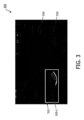
[028] 図1は、本開示の原理によるH/R定量化のための例示的なプロセスのフロー図100を示す。H/R定量化プロセスは、例えば、超音波検査技師が超音波画像データを取得している間にリアルタイムで行われる。例えば、リアルタイム超音波イメージング(ステップ110)中に、例えばユーザ入力に応答して、インテリジェント肝スキャンモードが起動される(ステップ112)。いくつかの実施例では、インテリジェント肝スキャンモードを起動するためのユーザ入力は、イメージングの前又は開始時に、ユーザによるグラフィカルユーザ制御(例えば、図3参照)の選択に応答して、又はインテリジェント肝スキャンモードを呼び出すように適切に構成された任意の他のタイプのユーザ制御の動作に応答して生成される。他の実施例では、インテリジェント肝スキャンモードは、例えばテキストフィールドにおけるスキャンの性質(例えば、肝臓)の指定に応答して、音声コマンドに応答して、又は、画像データ若しくは他の補助データ(例えば、患者病歴、以前の患者検査)に基づいてスキャンの性質を決定するシステムによって自動的に、異なるタイプの入力に応答して起動される。インテリジェントの肝スキャンモード中に、システムは、以下でさらに詳細に説明するように、1つ以上の命令セットを実行する。 [028] FIG. 1 depicts a flow diagram 100 of an example process for H/R quantification in accordance with the principles of this disclosure. The H/R quantification process is performed in real time, for example, while a sonographer is acquiring ultrasound image data. For example, during real-time ultrasound imaging (step 110), an intelligent liver scan mode is activated (step 112), eg, in response to user input. In some embodiments, the user input to activate the intelligent liver scan mode is responsive to a user's selection of a graphical user control (see, e.g., FIG. 3), prior to or at the beginning of imaging, or the intelligent liver scan mode generated in response to any other type of user-controlled action suitably configured to invoke the mode. In other embodiments, the intelligent liver scan mode is activated, e.g., in response to specifying the nature of the scan (e.g., liver) in a text field, in response to a voice command, or in response to image data or other ancillary data (e.g., The system determines the nature of the scan based on patient history, previous patient examinations) and is automatically triggered in response to different types of input. During the intelligent liver scan mode, the system executes one or more sets of instructions, as described in further detail below.
[029] 図1に示されるように、インテリジェント肝スキャンモード101の間、システムは、ビューマッチング、自動画像キャプチャ、ROI特定、及びエコー強度比定量化のための1つ以上の命令セットを実行する。図1の例示的なプロセスでは、インテリジェント肝スキャンモード101の起動の後、プロセスは、ビューマッチングステップ(ステップ114)に進み、H/R比の定量化に適した画像ビューが特定される。このプロセスの間、システムは、H/R比の定量化に適したビューに対応するライブ超音波画像を示す信頼メトリックを決定及び/又は(例えば、ユーザに表示するために)出力する。上述したように、H/R比定量化に適切なビューは、肝臓/右腎臓サジタルビューであるので、システムは、画像が適切な画像ビュー(ターゲット画像ビューとも呼ぶ)に対応するかどうかを認識するようにトレーニングされるか、又は他の方法で構成されていてよい。いくつかの実施形態では、ビューマッチングサブプロセスは、1つ以上の機械学習画像分類モデルを用いて行われるか又は強化される(ステップ115)。このような実施例では、適切な画像分類を行うようにトレーニングされた機械学習画像分類モデル(又は分類ニューラルネットワーク)に、生体組織の1つ以上の超音波画像(例えば、患者の肝臓のリアルタイム超音波画像)が提供される。分類ニューラルネットワークは、各入力画像を1つ以上の分類(例えば、「一致」、「一致/不一致」、又は一致と不一致との間の、一致の品質を示す任意の数の中間カテゴリ)に分類し、分類又は他の何らかの形式の信頼メトリック(例えば、コールドホットカラーバーにグラフィカルに表示され得る数値)を出力する。いくつかの実施例では、プロセスは、一致として分類される画像が特定されると(例えば、分類の結果が表示されることなく)、ステップ116に自動的に進む。他の実施例では、ステップ114におけるビューマッチングプロセスは、追加的に又は代替的に、現在知られている又は今後開発される他の画像処理及び分類技術によって行われてもよい。
[029] As shown in FIG. 1, during intelligent
[030] システムは、適切な画像ビューを表すものとして特定された画像を自動的にキャプチャして(例えば、ローカルメモリに記憶して)(ステップ116)、H/R比定量化のための後続のステップに進んでもよい。例えば、システムは、例えば、従来の画像処理技術を使用して、又は好ましくは機械学習画像セグメンテーションモデルを使用して(ステップ119)画像セグメンテーション(ステップ118)を行い、異なるタイプの組織(例えば、肝臓及び腎臓)に対応する画像内の領域を特定する。セグメンテーションは、適切なビューを特定するために、及び/又は測定ROIの配置を推奨するために使用される。適切なビューが特定されると、システムは、ビューを自動的に(すなわち、ユーザが「取得」ボタンを押す必要なく)キャプチャする。これは、ワークフローを改善し、ユーザがボタンを押す必要がある結果としてプローブが動いてしまうリスクを低減し、したがって、取得された画像ビューが所望の/ターゲットビューから逸脱するリスクを低減する。いくつかの実施形態では、システムは、(例えば、可聴音によって、又は自動的にフリーズモードになって、取得されたビューを表示することによって)所望のビューが取得されたことの通知を提供する。 [030] The system automatically captures (e.g., stores in local memory) images identified as representing suitable image views (step 116) for subsequent H/R ratio quantification. You may proceed to step . For example, the system may perform image segmentation (step 118), e.g., using conventional image processing techniques or preferably using a machine learning image segmentation model (step 119), to and kidney). Segmentation is used to identify appropriate views and/or to recommend measurement ROI placement. Once a suitable view is identified, the system automatically captures the view (ie, without the user having to press a "get" button). This improves the workflow and reduces the risk of the probe moving as a result of the user having to press a button, thus reducing the risk of the acquired image view deviating from the desired/target view. In some embodiments, the system provides notification that the desired view has been obtained (e.g., by an audible tone or by automatically entering freeze mode and displaying the obtained view). .
[031] 次いで、システムは、ガイダンスを提供するか、又は、H/R定量化のためのROIを自動的に選択する。例えば、システムは、第1及び第2のROI(例えば、肝臓及び腎臓のROI)を配置するための場所の1つ以上の適切なペアを特定する。システムは、(例えば、ペアリングを示すために同じペア内のROIを同じ色を使って表示するか、又はペアを順番に表示して、ユーザがペアのセットをスクロールすることを可能にすることによって)適切なペアをユーザに表示し、ROIのペアのユーザ選択を待つ。あるいは、システムは、ROIのペアを自動的に選択し、H/R比を計算するためにステップ120に進んでもよい。適切なROIのペアは、画像内の同じ深さにあるように、第1及び第2のROIがそれぞれ肝臓及び腎臓組織内にあるように、またROIがイメージングアーチファクトとなる傾向がある領域(例えば、組織間の境界に近すぎるか又は重なり合う、血管又は他の不均一な身体構造に近いか又は重なり合う)内にないように特定される。さらに、推奨されるROIは、ROIが(腎洞及び腎髄質を避けた)腎皮質内の場所に確実に配置され、かつ、肝臓の場合は、ROIが血管又は病変のない肝実質に確実に配置されるように、システムによって適応的に(例えば、腎皮質及び肝臓のサイズ及び形状に基づいて)定義される。複数のROIペアがユーザに提案されてユーザ選択を可能にし、測定精度を向上させる。又は、場合によっては、H/R比定量化は、同じ画像上の複数のROIペアに対して行われて、より良好な測定性能が達成される。 [031] The system then provides guidance or automatically selects the ROI for H/R quantification. For example, the system identifies one or more suitable pairs of locations to place first and second ROIs (eg, liver and kidney ROIs). The system may (e.g., display ROIs within the same pair using the same color to indicate pairing, or display pairs sequentially to allow the user to scroll through the set of pairs). ) displays the appropriate pair to the user and awaits the user's selection of the ROI pair. Alternatively, the system may automatically select a pair of ROIs and proceed to step 120 to calculate the H/R ratio. A suitable ROI pair should be such that the first and second ROIs are at the same depth within the image, that the first and second ROIs are within liver and kidney tissue, respectively, and that the ROIs are located in areas prone to imaging artifacts (e.g. , close to or overlapping boundaries between tissues, close to or overlapping blood vessels or other non-uniform body structures). Additionally, the recommended ROI is to ensure that the ROI is located within the renal cortex (avoiding the renal sinuses and medulla) and, in the case of the liver, to ensure that the ROI is in blood vessels or uninvolved liver parenchyma. be adaptively defined by the system (e.g., based on the size and shape of the renal cortex and liver) to be placed. Multiple ROI pairs are suggested to the user to allow user selection and improve measurement accuracy. Alternatively, in some cases, H/R ratio quantification is performed on multiple ROI pairs on the same image to achieve better measurement performance.
[032] ステップ120において、システムは、例えば、ROI内のすべてのピクセルのエコー強度の平均値、中間値、中央値、又は他の何らかの統計的に適切な表現などの、各ROIのエコー強度の代表値を決定し、2つの代表エコー強度値の比をとることによって、H/R比を計算する。計算されたH/R比は、画像と共に、例えば、画像上の注釈として、画像ファイルのヘッダに添付されるメタデータとして、レポートにアーカイブされる測定値として、又は任意の他の適切な関連付けを使用して記憶され、次いで、注釈付けされた/添付された画像は、(最初はローカルに、検査の完了時には、例えば、外部記憶装置に長期保管で)記憶され、これにより、イメージングデータ及び測定値は、臨床決定支援のために使用できる(ステップ122)。
[032] In
[033] 理解されるように、図1のステップ及びその配列は、単に例示のためのものであり、ステップの組み合わせ、再配列、追加、又は削除などの変形形態が企図される。例えば、図1のプロセスは、リアルタイムイメージングのコンテキストで示されているが、当然ながら、プロセスは以前に取得されたデータを用いて行ってもよい。例えば、インテリジェント肝スキャン特徴を起動したとき、システムは、肝臓及び腎臓を含む被検者のボリュームの以前に取得された3D画像データのセットを受信し、3D画像データ内の各スライスをスクロールするように進んで、ステップ114を参照して説明されたように、H/R比定量化の適切なビューを表す適切なスライス又はMPRビューを特定する。適切なビューが特定されると、システムは、前述したように、画像セグメンテーション及びH/R比定量化に進み、次いで、抽出されたMPRビュー及び計算された測定値を後続の診断目的のために記憶する。 [033] As will be appreciated, the steps and arrangement thereof in FIG. 1 are for illustration only, and variations such as combinations, rearrangements, additions, or deletions of steps are contemplated. For example, although the process of FIG. 1 is shown in the context of real-time imaging, it will be appreciated that the process may be performed using previously acquired data. For example, when activating the Intelligent Liver Scan feature, the system receives a set of previously acquired 3D image data of a subject's volume containing the liver and kidneys and scrolls through each slice within the 3D image data. Proceeding to identify the appropriate slice or MPR view representing the appropriate view for H/R ratio quantification, as described with reference to step 114. Once a suitable view is identified, the system proceeds with image segmentation and H/R ratio quantification, as described above, and then uses the extracted MPR views and calculated measurements for subsequent diagnostic purposes. Remember.
[034] 別の実施例では、例えば、画像セグメンテーションを行うようにトレーニングされた1つ以上のニューラルネットワークを使用して、ビューマッチングサブプロセスとセグメンテーションサブプロセスとを組み合わせてもよい。画像セグメンテーションは、画像が両方のタイプの組織を含むかどうか、また、信頼性のあるH/R比定量化のために必要とされる十分な量の2つのタイプの組織を含むかどうかを決定するために使用されるので、適切なビューの特定の間に、ステップ114において使用される。次に、ステップ118及び119を参照して説明したように、ニューラルネットワークによって生成された画像セグメンテーションを、(例えば、システムによるガイダンス又は自動選択のために)ROI配置のために使用できる。このようなシナリオでは、ステップ119の機械学習画像セグメンテーションモデルは、プロセスの早期に(例えば、ステップ112の後に)呼び出されてもよく、入力画像(例えば、リアルタイム画像フレーム)は、画像ビューマッチングのためにステップ119のニューラルネットワークに提供されてもよく、これは、分類モデル115を不要にする。このようなシナリオでは、自動画像キャプチャ(このプロセスはリアルタイムイメージング中に行われると仮定する)が画像セグメンテーションステップ119の後に続く。任意の数の他の変形又は組合せも可能であり、本開示を考慮すると理解されるであろう。
[034] In another example, the view matching sub-process and the segmentation sub-process may be combined, for example, using one or more neural networks trained to perform image segmentation. Image segmentation determines whether an image contains both types of tissue and whether it contains sufficient amounts of the two types of tissue required for reliable H/R ratio quantification. During the identification of the appropriate view, it is used in step 114. The image segmentation generated by the neural network can then be used for ROI placement (eg, for guidance or automatic selection by the system), as described with reference to
[035] 図2は、本開示のいくつかの実施例によるシステム200のブロック図を示す。図2のシステムは、プロセス100若しくはその任意のサブプロセスを少なくとも部分的に具現化するか、又は、それを行うために使用される。図2は、超音波トランスデューサ又はプローブ211、ビームフォーマ220、コントローラ224、及び信号プロセッサ222を含む超音波データ取得ユニット210を示す。図2はまた、ディスプレイ238を含むユーザインターフェース236と、メモリ229と、少なくとも1つの画像データプロセッサ223とを示しており、これらはすべて、例えばデータバス226を介して超音波データ取得ユニット210に通信可能に結合されている。図2に示すシステム200の構成要素及びその配置は、単に例示的であり、構成要素の組み合わせ、再配置、追加、又は除去などの変形形態が企図される。
[035] FIG. 2 depicts a block diagram of a
[036] 超音波データ取得ユニット210は、超音波画像データ232を取得する。超音波画像データは、リアルタイムで(すなわち、被検者を超音波スキャンすることによって画像データが取得されるにつれて)ディスプレイ238に表示される。超音波データ取得ユニット210は、典型的な超音波スキャナの構成要素のいくつか又はすべてを含んでいてもよい。例えば、超音波データ取得ユニット210は、超音波センサアレイ212を含む超音波トランスデューサ又はプローブ211を含む。センサアレイ212は、生体組織216(例えば、肝臓、腎臓、乳房、心臓組織、又は被検者の他のタイプの生体組織)に向けて超音波214を送信し、生体組織216からエコー218を検出して、生体組織216を超音波イメージングする。いくつかの実施例では、イメージングされた組織216は、少なくとも2つの異なるタイプの組織、例えば、肝実質217及び腎実質219を含む。例えば、線形アレイ、曲面アレイ、又はフェーズドアレイである様々なトランスデューサアレイを使用できる。アレイ212は、例えば、2D及び/又は3Dイメージングのための仰角寸法及び方位角寸法の両方でスキャンすることができるトランスデューサ素子の2次元アレイを含む。超音波データ取得ユニット210は、信号プロセッサ222を含み、これは、センサアレイ212と、一緒に収容されていても、物理的に分離されていて、通信可能に(例えば、有線又は無線接続を介して)結合されていてもよい。例えば、アレイ212は、ハンドヘルドプローブ内に配置されていて、一方、信号プロセッサ222は、超音波システムベース230内に配置されていて、場合によっては、タブレットなどのポータブルコンピューティングデバイス内に具現化されていてもよい。
[036] Ultrasonic
[037] アレイ212は、アレイ212の動作を制御するビームフォーマ220を介してシステムベース230に結合される。いくつかの実施形態では、ビームフォーマ220が1つ以上のビームフォーマ(例えば、超音波システムベース内のメインビームフォーマと組み合わせられるマイクロビームフォーマ、送信及び受信マイクロビームフォーマ及び/又はメインビームフォーマの組み合わせ)を含む。ビームフォーマ220は、アレイ212による超音波の送信及びエコー信号の受信を制御する。いくつかの実施形態では、ビームフォーマ220は、プローブ内の超音波アレイと同じ場所に配置され、超音波センサアレイ212のセンサ素子のグループによる信号の送信及び/又は受信のためにセンサ素子のグループに作用するマイクロビームフォーマを含む。いくつかの実施形態では、マイクロビームフォーマは、メインビームフォーマを高エネルギー送信信号から保護するように送信と受信とを切り替える送信/受信(T/R)スイッチ(図示せず)に結合される。いくつかの実施形態では、例えば、ポータブル超音波システムでは、T/Rスイッチ及びシステムの他の要素は、システムベース230ではなく超音波プローブに含まれていてもよい。超音波ベースは、通常、信号処理及び画像データ生成のための回路だけでなく、ユーザインターフェースを提供するための実行可能命令を含むソフトウェア及びハードウェア構成要素を含む。いくつかの実施形態では、超音波プローブは、無線接続(例えば、WiーFi(登録商標)、Bluetooth(登録商標))を介して、又は有線接続(例えば、並列又は直列データ伝送用に構成されたプローブケーブル)を介して、超音波システムベースに結合される。
[037]
[038] システム200は、アレイ212によって検出されたエコーから超音波画像を生成するための1つ以上の処理構成要素を含む。例えば、システム200は、超音波画像232を生成するためにトランスデューサ211から受信されたエコー信号を処理する信号プロセッサ222と、システムのディスプレイ上に超音波画像を提示する少なくとも1つの画像データプロセッサ223とを含む。超音波データ取得ユニット210は、ユーザインターフェース236を含むか、又はそれに動作可能に結合される。ユーザインターフェース236は、信号プロセッサ222を収容するシステムベース230と一体化されるか、又は物理的に接続される。いくつかの実施形態では、ユーザインターフェースの少なくともいくつかの構成要素は、信号プロセッサ222に無線で接続されていてもよい。
[038]
[039] ユーザインターフェース236は、超音波画像232、場合によっては対話型グラフィカルユーザインターフェース(GUI)構成要素を表示するためのディスプレイ238を含む。ユーザインターフェース236はまた、システム200の動作を制御するための1つ以上のユーザ制御部237を含む。いくつかの実施形態では、ユーザ制御部237は、システムベース230のコントロールパネル上に提供される1つ以上のハード制御部(例えば、ボタン、ノブ、ダイヤル、エンコーダ、マウス、トラックボールなど)を含み得る。いくつかの実施形態では、ユーザ制御部237は、タッチセンシティブディスプレイ上に提供されるソフト制御部(例えば、GUI制御素子又は単に、GUI制御部)を追加的に又は代替的に含み得る。システム200はまた、ローカルメモリ229を含む。ローカルメモリは、1つ以上のハードディスクドライブ、ソリッドステートドライブ、又は不揮発性メモリを含む任意の他のタイプの適切な記憶デバイスによって提供される。ローカルメモリ229は、画像データ、実行可能命令、又はシステム200の動作に必要な他の任意の情報を記憶する。いくつかの実施例では、システム200はまた、外部メモリ、例えば、画像データ及び他の患者情報の長期記憶のための画像保管及び通信システム(PACS)記憶デバイスに(有線又は無線接続を介して)通信可能に接続されていてもよい。
[039]
[040] 信号プロセッサ222は、センサアレイ212及び/又はビームフォーマ220に通信可能、動作可能、及び/又は物理的に結合される。信号プロセッサ222は、センサアレイ212によって検出された超音波エコー218を表す、フィルタリングされていない無秩序の超音波データを受信する。このデータから、信号プロセッサ222は、超音波画像データを生成し、この超音波画像データは、例えば、プロセッサ223によって、表示のために画像232に適切に構成される。例えば、信号プロセッサ222は、帯域通過フィルタリング、デシメーション、I及びQ成分分離、及び高調波信号分離などの様々なやり方で受信エコー信号を処理する。また、信号プロセッサ222はまた、スペックル低減、信号複合化、及び雑音除去などの追加の信号強化を行ってもよい。次いで、信号プロセッサ222は、振幅検出、又は、体内の構造のイメージングのための任意の他の既知の又は後で開発される技術を採用するなどして、成分信号からBモード画像データを生成する。Bモード画像データはさらに、例えば信号をそれが受信された空間関係で所望の画像フォーマットで配置するために、スキャン変換によって処理される。例えば、スキャン変換は、信号を、2次元(2D)扇形フォーマット、又は角錐状若しくは他の方法で成形された3次元(3D)フォーマットに配置する。Bモード画像データは、あるいは又はさらに、例えば米国特許第6,443,896号(Detmer)に説明されているように、身体内のボリュメトリック領域内の共通平面内の点から受け取ったエコーを、その平面の超音波画像(例えば、Bモード画像)に変換するマルチプレーナリフォーマッタによって処理されてもよい。システム200の1つ以上のプロセッサ(例えば、プロセッサ222又は223)は、さらに又はあるいは、例えば米国特許第6,530,885号(Entrekin他)に説明されているように、Bモード画像データのボリュームレンダリング(すなわち、所与の基準点から見た3Dデータセットの画像)を生成してもよい。
[040]
[041] 信号処理及び画像データの生成は、オペレータが組織216を超音波スキャンする際にリアルタイムで行われ、それにより、画像データは、被検者のリアルタイム(すなわち、ライブ)画像として表示される。あるいは、画像232は、システム200に関連付けられているメモリ(例えば、ローカル又は外部メモリ)に記憶された、以前に取得された画像データから生成されてもよい。上述したように、超音波データ取得ユニット210は、例えば、アレイ212による信号の送受信だけでなく、システム200の特定の信号及び画像処理機能を制御するために、システム200のイメージングパラメータを設定するコントローラ224を含む。コントローラ224はとりわけ、システム200のイメージングパラメータを制御又は設定し、この設定は、アレイ212による信号の送信及び検出のために、アレイの素子の励起を制御する際にビームフォーマ220によって利用される。コントローラ224によって適用される設定はまた、例えば、画像の表示のための圧縮されたダイナミックレンジ、又は他の画像処理もしくは表示設定を制御することによって、取得された超音波データの信号及び画像処理に影響を及ぼす。上述したように、ビームフォーマの制御下でのトランスデューサアレイ212からの超音波パルスの送信は、T/Rスイッチに結合され、ユーザインターフェース236のユーザ操作からの入力を受信する送信/受信コントローラによって指示される。コントローラ224によって制御され得る別の機能は、電子的ステアリング可能なアレイの場合、ビームがステアリングされる方向である。ビームは、トランスデューサアレイ212から(トランスデューサアレイ212に直交して)まっすぐ前にステアリングされても、又はより広い視野のために異なる角度でステアリングされてもよい。
[041] The signal processing and image data generation occurs in real time as the operator ultrasound scans the
[042] 図2に示されるように、データ取得ユニット210は、例えば、本明細書に説明されるように、インテリジェント又は誘導肝スキャンを行うために、生体組織のインテリジェントスキャン(コンピュータ支援スキャン又はAI支援スキャンとも呼ぶ)に関連する機能のうちの1つ以上を行う少なくとも1つのプロセッサ223に通信可能に接続される。プロセッサ223は、1つ以上の処理ユニット(例えば、1つ以上のシングル又はマルチコアCPU、単一のGPU又はGPUクラスタ、又は、例えば並列処理のために構成された複数のプロセッサの任意の配置)を含み、本明細書に説明する機能を行うように一意的に構成されている。例えば、プロセッサ223は、リアルタイム画像を受信し、リアルタイム画像の信頼メトリックを出力する。信頼メトリックは、ターゲット画像ビューに従ってリアルタイム超音波画像が生体組織を視覚化する確率を示す。少なくともいくつかの実施形態では、プロセッサ223は、少なくとも1つの人工ニューラルネットワークを使用して、信頼メトリックを生成する。信頼メトリックが閾値を超えると決定されると、プロセッサ223はさらに、リアルタイム超音波画像を自動的にキャプチャし(すなわち、ローカルメモリに記憶し)、第1及び第2の関心領域(ROI)の場所を決定し、第1及び第2のROIのエコー強度値の比を計算する。信頼メトリックが閾値を超えない場合、プロセッサ223はさらに、1つ以上の連続するリアルタイム画像フレームを自動的に受信し、1つ以上の連続するリアルタイム画像フレームそれぞれの信頼メトリックを出力して、エコー強度比定量化のための適切な画像フレームを特定するプロセスを続ける。
[042] As shown in FIG. 2, the
[043] 1つの例示的な実施形態では、システム200は、肝組織を超音波検査するために具体的に構成され、したがって、画像フレーム内の生体組織は、肝組織、腎組織、又はこれら2つの組合せの少なくとも一部を含み、ニューラルネットワークは、肝臓/腎臓エコー強度比を計算するのに適した肝臓及び右腎臓サジタルビューに所与の入力画像が対応する確率を定量化する信頼メトリックを生成するように具体的にトレーニングされる。このために、ニューラルネットワークは、画像が、閾値を超える数値に関連する少なくとも1つのカテゴリを含む複数のカテゴリのうちの1つ以上に分類されるべき確率を決定するようにトレーニングされる。本明細書の実施例は、肝イメージングのコンテキストで説明されているが、当然ながら、本開示の原理は、他のイメージング用途に適用されてもよい。例えば、生体組織におけるエコー強度を使用して、組織組成、組織の均質性又は不均質性、肝臓以外の生体組織における水及び/又は脂肪含有量を評価することができ、したがって、本明細書に詳細に説明される肝イメージングの実施例以外の他の用途において、組織を特徴付ける又は診断することができる。
[043] In one exemplary embodiment, the
[044] プロセッサ223は、生体組織のインテリジェントスキャンに関連する機能を行うことに加えて、画像データ及び関連情報の表示に関連する他の機能を提供する。いくつかの実施形態では、プロセッサ223は、表示プロセッサ234を含み、表示プロセッサは、注釈を生成し、ディスプレイ238に、注釈を画像データ、(例えばビューマッチング中のフィードバックを提供するための)グラフィカルインジケータ、及び/又はシステム200のインテリジェントスキャンモードに関連するグラフィカルユーザインターフェース構成要素のいずれかと共に提示させる機能をさらに含む。例えば、表示プロセッサ234は、ディスプレイ238上に表示される前さらなる強調、バッファリング、及び一時記憶のために画像データを受信する。ディスプレイ238は、LCD、LED、OLED、又はプラズマディスプレイ技術などの、種々の既知のディスプレイ技術を用いて実施されるディスプレイデバイスを含み得る。図2では、例示のために、エンジン227と表示プロセッサ234とは別個の構成要素として示されているが、実際には、これらの構成要素(及び本明細書で説明される任意の他の処理構成要素)の機能は、単一のプロセッサ又は一緒に(例えば、並列に)動作するように構成されたプロセッサのクラスタに統合されていてもよい。
[044] In addition to performing functions related to intelligent scanning of biological tissue,
[045] さらに説明されるように、プロセッサ223は、ソフトウェア(例えば、ソースコード又はコンパイルされた/機械命令の形態の実行可能命令)及びハードウェア構成要素(例えば、実行可能命令及び/又はエンジン227の機能のうちの1つ以上を行うように具体的にプログラムされた特定用途向け集積回路ASICなどの配線回路によってプログラム可能な1つ以上のプロセッサ)の任意の適切な組合せで具現化されるエコー強度比定量化エンジン227を含む。エンジン227は、図1を参照して説明したステップのうちの1つ以上を行うための機能を含む。いくつかの実施例では、エンジン227の機能は、プロセッサ実行可能命令225によって実装される。プロセッサ実行可能命令225は、プロセッサ223によって実行されると、イメージングのための適切なビューの特定及び/又は2つのRIOのエコー強度比の定量化に関連する機能を行うようにプロセッサを構成又はプログラムする。いくつかの実施形態では、本明細書でさらに説明するように、エンジン227は、エンジン227の機能の1つ以上を行うようにトレーニングされた少なくとも1つのニューラルパーセプトロンの人工ネットワーク228(本明細書では人工ニューラルネットワーク又は単にニューラルネットワークとも呼ぶ)を含む。任意の適切なタイプの機械学習アルゴリズム(例えば、生成的、判別的、又はこれらの組合せ)及び/又はアーキテクチャを使用して、ニューラルネットワーク228を実装できる。いくつかの実施例では、ニューラルネットワーク228は、画像分類、画像セグメンテーション、画像比較、又はこれらの任意の組合せを実行するようにトレーニングされている深層ニューラルネットワーク、より具体的には深層畳み込みニューラルネットワークを含む。(例えば、PACS又はクラウドストレージ内に)記憶される医用画像データや、トレーニング用画像に必要なラベリングを提供可能な注釈付き画像データのボリュームが増加すると共に、高品質な臨床画像の利用可能性が増加しており、これを利用して、医用画像データに対して分類、セグメンテーション、物体認識、又は他の画像処理タスクを行うようにニューラルネットワークをトレーニングすることができる。トレーニング画像は、イメージングシステムによって生成された完全な画像を含む必要はなく、関連するターゲット生体組織又は器官の医用画像のパッチ又は部分を含むことが理解されるであろう。
[045] As further described,
[046] ニューラルネットワーク228は、任意の適切なアーキテクチャを有することができ、したがって、任意の数の入力層、出力層及び隠れノード層を任意の適切な構成(例えば、畳み込み層、正規化層、プーリング層、及び/又は高密度若しくは全結合層)で含む。いくつかの実施例では、ネットワーク228は、所望の結果を生成するようにトレーニングされたより大きなネットワークを形成する1つ以上のサブネットワークの任意の適切な構成を含む。さらなる実施例では、ニューラルネットワーク228は、例えば、ニューラルネットワーク228に入力されるデータの前処理及び/又はネットワーク228の出力の後処理を実行して、エコー強度比定量化エンジン227から適切な結果を生成するように、追加のプログラムに動作可能に関連付けられる。
[046]
[047] 上述したように、システム200の構成要素のいくつか又はすべては、(例えば、システムベース230内に)同じ場所に配置され、(例えば、データバス226を介して)通信可能に接続される。さらに又はあるいは、システム200の構成要素は、1つ以上の有線又は無線接続を介して遠隔構成要素に接続されてもよい。例えば、システムベース230はさらに、外部ストレージ235(例えば、外部ドライブ又は医療施設のPACS記憶デバイス)に通信可能に結合される。いくつかの実施形態では、エンジン227の機能のいくつか又はすべては、クラウドサーバなどのリモートコンピューティングデバイス239内に常駐していてもよい。例えば、1つ以上のニューラルネットワーク228は、リモートコンピューティングデバイス239上に常駐して、実行され、システムベース230(例えば、タブレット超音波イメージングシステムなどのポータブルシステム)は、分類及び/又はセグメンテーションのためにライブ画像をクラウドに送信し、プローブ211によって取得された関連画像データと共に表示するために、エンジン227の出力(例えば、信頼メトリック)を受信する。
[047] As noted above, some or all of the components of
[048] 本明細書に説明されるように、プロセッサ223は、エコー強度比定量化(例えば、H/R比を使用する脂肪定量化のための肝イメージングの場合)に適したビューを(例えば、入力されるリアルタイム画像から)を特定し、エコー強度比の計算に関連するさらなる処理のために、特定された適切なビューを自動的にキャプチャする。これらのプロセスは、集合的にインテリジェントスキャン又はAI支援スキャンと呼ぶ。図3は、本明細書の実施例による超音波イメージングシステムのインテリジェントスキャンモードを起動し、したがって、プロセッサ223の関連機能を呼び出すために使用するグラフィカルユーザインターフェース(GUI)300の一例を示す。GUI300は、超音波システム(例えば、システム200)のタッチセンシティブディスプレイ上に提供され、システムの機能を選択又は起動するための制御部310の1つ以上の対話型GUI要素を含む。例えば、GUI300は、システム200のインテリジェントスキャンモード301(AI支援の肝スキャン)を起動するための制御部310(例えば、脂肪定量化ソフトボタン)を含む。システム200の任意の数のAI支援機能を起動するために、任意の数のそのような制御部が提供されていてよい。インテリジェントスキャンモードで動作すると、システムは、ユーザにガイダンスを提供するか、又は対応するスキャンプロトコルの特定の動作を自動化する。
[048] As described herein, the
[049] いくつかの実施例では、システムは、組織の適切なビューの取得においてユーザを誘導する。図4のパネルa~cは、AI支援の肝スキャン中に提供され得る追加のグラフィック表示を示す。例えば、制御部310-1を介する起動時、システムは、例えば、タッチセンシティブディスプレイ上又はメインディスプレイ上の新しいウィンドウに、アイコン410(図4、パネルa)などの1つ以上のガイダンスアイコンを表示する。このアイコンは、適切な解剖学的ビューを取得するためのプローブの配置においてユーザを誘導するようにデザインされたグラフィックを含む。さらに又はあるいは、システムは、所望の解剖学的ビュー内の器官の相対位置を示すグラフィックであるアイコン412(図4、パネルb)を表示してもよい。アイコン412は、ユーザ(特に、未経験のユーザ)が、スキャンを行う前又はスキャンを行っている間に最適なビューを視覚化するのを支援する。アイコン410、412の1つ以上は、スキャンセッションの開始時に一度表示されても、ユーザがスキャンを行い、システムがディスプレイのアクティブ領域420内にリアルタイム画像422を表示している間に、ディスプレイ上に同時に(例えば、縮小/サムネイル形式で)表示されてもよい(図4、パネルc)。オペレータがプローブを患者に当て、音響ウィンドウを取得すると、システムは(例えば、パネルcに示すように)ライブ画像表示を自動的に起動し、システムは、被検者のリアルタイム画像、すなわち、ライブ画像の表示を開始する。いくつかの実施形態では、システムは、(例えば、プローブの視野内の所望の組織をより良好にキャプチャするために、ユーザにプローブをサジタル面上に沿って又はつま先からかかとに移動させるための視覚的又は聴覚的命令によって)プローブの操作方法に関する命令をユーザに提供するなど、システムがバックグラウンドで画像ビュー解析を行う間に、追加のガイダンスを提供する。
[049] In some examples, the system guides the user in obtaining an appropriate view of the tissue. Panels a-c of FIG. 4 illustrate additional graphical displays that may be provided during an AI-assisted liver scan. For example, upon activation via control 310-1, the system displays one or more guidance icons, such as icon 410 (FIG. 4, panel a), e.g., on a touch-sensitive display or in a new window on the main display. . This icon includes a graphic designed to guide the user in positioning the probe to obtain the appropriate anatomical view. Additionally or alternatively, the system may display an icon 412 (FIG. 4, panel b), which is a graphic indicating the relative position of the organ within the desired anatomical view.
[050] インテリジェントスキャンモード中に、各取得フレームの画像データは、リアルタイムで適切なビューの特定のためにエンジン227に提供される。上述したように、ビュー特定(又はビューマッチング)は、人工ニューロンの1つ又は任意の数の積み重ねられた、接続された、又はその他の適切に構成されたネットワークを含むニューラルネットワーク228によって行われる。いくつかの実施例では、ニューラルネットワーク228は、各入力画像について、信頼メトリック(本明細書ではマッチングスコアとも呼ぶ)を出力する深層畳み込みネットワークを含む。信頼メトリック(又はマッチングスコア)は、所与の画像が所望の又はターゲット画像ビューに対応する確率又は信頼レベルの指標を提供する。マッチングスコアは、少なくとも部分的に、分類、セグメンテーション、物体検出、又は画像の内容を解析するための他の技法、又はこれらの任意の適切な組合せによって導出される。いくつかの実施例では、深層畳み込みネットワークは、画像セグメンテーションを行うようにトレーニングされた完全畳み込みネットワークを含む。いくつかの実施形態では、深層畳み込みネットワークは、物体検出、画像セグメンテーション、又は両方を行う少なくとも1つの畳み込みサブネットワークと、任意選択で、物体検出又はセグメンテーションの出力を分類して信頼メトリックを生成する少なくとも1つの追加サブネットワークとを含む。いくつかの実施例では、完全畳み込みネットワークは、高密度(すなわち、ピクセルごとの)予測によく適しているため、画像を関連するピクセルの複数のセグメントに分割するように効果的にトレーニングできるので、画像セグメンテーションの機械学習に特によく適している。
[050] During intelligent scan mode, image data for each acquired frame is provided to
[051] 一例では、ネットワーク228(例えば、深層畳み込みネットワーク)は、各入力画像を複数のカテゴリのうちの1つに分類するように画像分類を行うようにトレーニングされる。深層畳み込みネットワークは、入力画像を受信する入力層と、分類(例えば、バイナリ分類か、又は入力画像が分類カテゴリのいずれか1つに関連する確率をリストしたベクトル)を出力する出力層と、畳み込み層、プーリング層、正則化層、及び全結合(又は高密度)層を含む任意の数の中間層とを含む。図5は、本開示のいくつかの実施例で使用され得る畳み込みネットワークの例示的なアーキテクチャを示す。ネットワーク500は、入力層510と、各々が1つ以上の正則化層及びプーリング層に関連付けられている4つの畳み込み層512と、2つから4つ(この特定の場合には3つ)の全結合層514とを含み、最後の全結合層が出力層514-3である。しかし、他の実施例では、ネットワークは、例えば、データセットの複雑さに応じて異なる数の層、例えば、より少ない又はより多い数の畳み込み層及び/又は全結合層を含み得る。入力層510は、入力画像501(例えば、肝組織及び/又は腎組織を視覚化する超音波画像)を受信する。画像501は、単一チャネル(グレースケール)又はマルチチャネル(カラー)画像であり得る。図示の例では、入力画像501は、150×150ピクセル解像度を有する3チャネルグレースケール画像であり、したがって、ネットワーク500に入力されるボリュームは、サイズ150×150×3を有するピクセル値の3次元アレイであるが、他の実施例では入力サイズが異なってもよい(例えば、128×128、256×256、又は任意の他の解像度の画像を受け入れる)ことが理解されよう。各畳み込み層において、複数のフィルタが入力画像に畳み込み演算を行い、特徴(又は活性化)マップ(例えば、層512-1で32個、層512-2で16個、層512-3で8個、及び層512-4で4個)のスタックである各畳み込み層の出力を生成する。プーリングを伴う畳み込み層に続いて、空間次元における入力サイズが縮小され(例えば、150から75へ、次いで37)、このダウンサンプリングは、一部のプーリングのタイプ(例えば、最大、平均、L2ノルムなど)、畳み込みストライド、及びプーリングストライドに依存する。図示の具体例では、入力画像は、最後の畳み込み層512-4の出力において、4つの37×37活性化マップのスタックに処理され、次いで、第1の全結合層514-1に提供され、第1の全結合層は32サイズのベクトルを出力する。次に、第1の全結合層514-1の出力は、それぞれ16及び2の出力サイズを有する2つの追加の全結合層514-2、514-3を通って伝播され、最後の全結合(すなわち、出力)層514-3において、2次元ベクトルを出力し、各次元は2つの、すなわち、バイナリ分類(例えば、一致又は不一致)カテゴリのいずれかに入る画像の確率を表す。図5に示す特定のアーキテクチャは、単に例示のために提供されたものであり、特定のアーキテクチャ、層の数、ならびに入力及び出力サイズは、他の実施例では異なってもよいことが理解されるであろう。例えば、他の実施形態では、ネットワーク500は、4、5、6又はそれよりも多い数の分類カテゴリを有するような、異なるサイズの分類ベクトルを(出力層514-3において)出力するようにトレーニングされてもよい。
[051] In one example, network 228 (eg, a deep convolutional network) is trained to perform image classification to classify each input image into one of a plurality of categories. A deep convolutional network consists of an input layer that receives an input image, an output layer that outputs a classification (e.g., a binary classification or a vector listing the probability that the input image is associated with any one of the classification categories), and a convolution layers, pooling layers, regularization layers, and any number of intermediate layers, including fully connected (or dense) layers. FIG. 5 illustrates an example architecture of a convolutional network that may be used in some embodiments of this disclosure.
[052] バイナリ分類(すなわち、一致又は最適なビュー、及び不一致又は準最適なビュー)の場合、ネットワークは、ラベル付けされた画像のセット(トレーニングデータとも呼ぶ)を使用してトレーニングされる。トレーニングデータは、(例えば、数百から数千の)多数の臨床画像を含み、各画像は、一致(又は最適なビュー)又は不一致(準最適なビュー)のいずれかとして(例えば、経験豊富な超音波検査技師又は臨床医によって)ラベル付けされている。図6は、トレーニングデータとして使用される画像600の一例を示す。それぞれが十分な量の肝組織及び腎組織の両方を視覚化する画像のセット610は、「一致」分類カテゴリに属するものとしてラベル付けされている。主に肝組織を示すか、又はH/R比定量化に適していない画像のセット612は、「不一致」分類カテゴリに属するものとしてラベル付けされている。トレーニングデータ600は、ニューラルネットワークに提供され、ネットワークのパラメータは、トレーニングプロセス全体にわたって(例えば、バックプロパゲーション又は他の技法によって)更新される。ニューラルネットワーク500の1つの実験的なバージョンでは、5400枚以上の臨床画像をトレーニング及び検証に使用した。トレーニング画像は、トレーニングセットと、テスト又は検証セットとに分割された。トレーニング及び検証データセットは、トレーニングのためにネットワークに提供されるラベル付き画像を含む。トレーニング中にネットワークに示されることのなかったラベル付きテスト画像を使用して、システムの性能がテストされ、これは、実験的な使用では、少なくとも85%の正確な予測を提供することが示された。このようにして、ニューラルネットワーク(例えばネットワーク500)はトレーニングされて、新しい未知の画像を、ネットワークがそれに対してトレーニングされた分類カテゴリの1つに分類する。
[052] For binary classification (i.e., matching or optimal views, and mismatching or suboptimal views), the network is trained using a set of labeled images (also referred to as training data). The training data includes a large number of clinical images (e.g., hundreds to thousands), with each image treated as either a match (or optimal view) or a mismatch (suboptimal view) (e.g., by an experienced labeled by the sonographer or clinician). FIG. 6 shows an example of an
[053] 理解されるように、ネットワーク500は、入力画像を3つ以上のカテゴリに分類するようにトレーニングされてもよい。このシナリオでは、トレーニングされているすべてのカテゴリがトレーニングデータで表現されるように、ネットワークは3つ以上のカテゴリにラベル付けされた画像でトレーニングされる。例えば、トレーニングデータは、不一致を表す画像(例えば、ビュー内に肝実質及び腎実質を共に含まない画像)、したがって、0の値でラベル付けされる画像と、画像内の肝臓及び腎臓の理想的な位置付けを含み、一致(又は最適なビュー)としてラベル付けされ、及び/又は1の値が割り当てられる画像とを含む。最適ビューと許容できないビューとの間のどこかに該当する残りの画像は、任意の数の中間カテゴリに分割され、対応して0と1との間の値でラベル付けされて、一致の質を示す。例えば、腎組織を含まない任意の画像を、例えば、ほとんど不一致(0.2)、許容できる一致(0.4)、良好な一致(0.6)、及び非常に良好な一致(0.8)と示すことができる。トレーニング画像の中間分類は、部分的に、経験豊富な超音波検査技師又は臨床医が判断したビュー、又は、画像中に視覚化されている肝組織及び腎組織の割合の計算、肝臓と腎臓との境界の場所などの定量的評価による質に基づいていてもよい。
[053] As will be appreciated,
[054] 本開示によるニューラルネットワークをトレーニングするために、VGGNet又はResNetのようなアーキテクチャなど、任意の適切なアーキテクチャを使用してもよく、また、「ブランクスレート」ネットワークを一から(すなわち、重みの事前構成なしに)トレーニングしてもよい。図7に示すように、必要とされるトレーニングデータの量を減らすために、(図7に示すように)Inception V3などの事前トレーニングされたネットワーク又は別のネットワークを開始点として使用できる。次いで、事前トレーニングされたネットワーク710は、具体的には、特定の臨床用途(この場合は肝イメージング)の医用画像(例えば、超音波画像712)のはるかに小さいトレーニングデータセットで医用画像データを分類するために微調整される。微調整は、例えば、Inception V3ネットワークの最後から2番目の層を、所望の分類(例えば、一致/不一致)を生成する新しい出力分類器714(例えば、全結合層から構成される)に入力することによって、又は、Inception V3ネットワークによって出力された特徴ベクトルを、トレーニングデータが少なくて済む新しい分類器に提供することによって行われる。 [054] Any suitable architecture may be used to train a neural network according to this disclosure, such as a VGGNet or ResNet-like architecture, or a “blank slate” network (i.e., a may be trained (without prior configuration). To reduce the amount of training data required, a pre-trained network such as Inception V3 (as shown in FIG. 7) or another network can be used as a starting point. The pre-trained network 710 then specifically classifies medical image data on a much smaller training dataset of medical images (e.g., ultrasound images 712) for a particular clinical application (in this case liver imaging). fine-tuned to do so. Fine-tuning, for example, inputs the penultimate layer of the Inception V3 network into a new output classifier 714 (e.g., composed of fully connected layers) that produces the desired classification (e.g., match/mismatch). or by providing the feature vectors output by the Inception V3 network to a new classifier that requires less training data.
[055] 上述したように、適切なビューが特定されると、システムは、適切なビューを表す画像を自動的にキャプチャする(例えば、ローカルメモリに記憶する)。適切なビューの特定は、エンジン227が一致を示すメトリック又はスコアを出力することに基づき得る。例えば、所与の画像が、75%以上で良好ビューのカテゴリ内であり、25%以下で不良ビューのカテゴリ内であると分類される場合、システムは、入力画像が適切なビューに対応すると決定する。同様に、非バイナリ分類の場合、システムは、例えば、分類値によって重み付けされた各分類の確率を合計することによって、ビューマッチングスコアを計算する。例えば、ネットワークが、画像をn個のカテゴリに分類するようにトレーニングされ(各カテゴリは、例えば0と1との間の一意の値に関連付けられる)、それぞれのカテゴリに対応する画像の確率を表す分類ベクトルy(c1、c2、cn)を出力する場合、エンジン227は、分類ベクトルの重み付けされた値を合計することによってビューマッチングスコアMを計算する。すなわち、
![]()
![]()
[056] いくつかの実施形態では、マッチングは、バックグラウンドで行われてもよいし、ユーザに対して実質的に透過的であってもよい。いくつかのそのような実施例では、ユーザがプローブを操作し、ディスプレイがリアルタイム画像を表示し続ける間は、システムが適切なビューを特定するまで、ビューマッチングプロセスによって生成される他の情報は提供されない。ビューが特定されると、システムはフリーズモードに入り、適切なビューを表す画像はディスプレイ上に(フリーズモードで)表示される。フリーズモードの自動起動は、適切なビューが特定されたことの指示を提供する。 [056] In some embodiments, matching may occur in the background or may be substantially transparent to the user. In some such embodiments, while the user manipulates the probe and the display continues to display real-time images, other information generated by the view matching process is not provided until the system identifies the appropriate view. Not done. Once a view is identified, the system enters freeze mode and an image representing the appropriate view is displayed on the display (in freeze mode). Automatic activation of freeze mode provides an indication that the appropriate view has been identified.
[057] インテリジェントスキャンモード中、システムは、適切なビューの取得においてユーザを支援するために(例えば、プローブの操作においてユーザを支援する命令の形態で)、ユーザにガイダンスを提供する。いくつかの実施形態では、システムは、システムのプロセッサ(例えば、プロセッサ223)によって計算されている信頼メトリックの現在値を表すグラフィカルインジケータを表示するなどによってガイダンスを提供する。 [057] During intelligent scan mode, the system provides guidance to the user (eg, in the form of instructions to assist the user in manipulating the probe) to assist the user in obtaining the appropriate view. In some embodiments, the system provides guidance, such as by displaying a graphical indicator representing the current value of the confidence metric being calculated by the system's processor (eg, processor 223).
[058] 図8は、グラフィカルインジケータを有する、超音波システムの例示的なスクリーンキャプチャを示す。グラフィカルインジケータは、任意の所与のライブ画像の信頼メトリックのリアルタイムの視覚的指示を提供するために動的に更新される。この例では、グラフィカルインジケータは、可動ゲージを有するカラーバー(例えば、ホット又は赤色が一致に対応し、コールド又は青色が不一致に対応するホットコールドカラーバー)の形態のマッチインジケータ820として実装される。図8のパネルa~dの各々は、肝組織802のライブ超音波画像810、812、814、及び816のスクリーンキャプチャを示し、各ライブ画像は、カラーバーマッチインジケータ820と同時に表示される。マッチインジケータ820は、現在表示されている画像フレームのビューマッチングスコアの値を示すためにカラーバーを上下に移動する動的構成要素822(例えば、スライドレベル又はバー)を含む。最小値及び最大値は、分類カテゴリの最小値及び最大値、ここでは0及び1に対応し、動的構成要素822は、計算された又は別の方法で導出されたビューマッチングスコアを表す。図示のように、画像810では、ビューマッチングスコアは約0.2であり、これは腎組織がビューに含まれていないことを反映する比較的低いマッチング確率を示す。ユーザがプローブを操作すると、システムは、連続するフレームについてビューマッチングスコアを連続的に再計算し、カラーバーに沿った動的構成要素822の位置を動的に更新する。画像816内のビューは、4つのビューマッチングスコアのうち最も高いものに関連付けられ、図8に示す4つのビューのうちの最良のものを表す。上述したように、好ましい実施形態では、ビューマッチングスコアは、ニューラルネットワークの動作に応答して生成されるが、ビューマッチングスコアは、従来のコンピュータビジョンアプローチ及び/又は手作りの特徴生成(例えば、キャニーエッジ検出、輝度勾配ヒストグラム、及びサポートベクターマシン)を追加的に又は代替的に使用して取得されてもよい。他の実施例では、一致インジケータは、ゼロ速度が最小値の信頼メトリックに対応し、最大速度が最大値の信頼メトリックに対応し、ダイヤル内の矢印が信頼メトリックの現在地を示すように動的に更新されるスピードダイヤルなど、異なるタイプのグラフィカル要素を使用して実装されてもよい。さらなる実施例では、信頼メトリックは、画像と共に数値的に表示されてもよい。他のグラフィカルインジケータを使用して、ディスプレイ上に信頼メトリックを視覚化してもよい。
[058] FIG. 8 shows an example screen capture of an ultrasound system with graphical indicators. Graphical indicators are dynamically updated to provide a real-time visual indication of confidence metrics for any given live image. In this example, the graphical indicator is implemented as a
[059] いくつかの実施形態では、ビューマッチングは、画像セグメンテーションを使用して行われる。例えば、図2に戻って参照すると、システム200が採用する1つ以上のニューラルネットワーク228は、入力画像をセグメント化し、画像のセグメンテーションに基づいて、画像がターゲットビューに対応するかどうか(例えば、画像がビュー内に組織/器官のターゲット配置を含むかどうか)の決定を行うようにトレーニングされる。ネットワーク228は、各入力画像のセグメンテーションマップを生成するようにトレーニングされた任意の数の層(例えば、畳み込み層、プーリング層、及び正則化層)を含む。非機械学習技法と同様に、セグメンテーションプロセスは、デジタル画像を複数の領域又はセグメント(すなわち、ピクセルのセット、又は、3D画像データの場合はボクセルのセット)に分割する。具体的な例では、ネットワーク228は、ピクセルごとに意味的セグメンテーションを行うようにトレーニングされ、それによって、画像内の各ピクセルを複数のカテゴリ(例えば、肝臓、腎臓、肺、モリソン窩、血管、病変など)のうちの1つに割り当てる。
[059] In some embodiments, view matching is performed using image segmentation. For example, referring back to FIG. 2, the one or more
[060] 図9は、画像セグメンテーションを行うようにトレーニングされた完全畳み込みニューラルネットワーク900の一例を示す。ネットワーク900は、ラベル付き画像(例えば、異なるタイプの組織の、手動又はコンピュータ支援のいずれかで描写された境界が重ね合わされた肝臓及び/又は腎臓の画像)を含むトレーニングデータを使用してトレーニングされる。したがって、ネットワーク900は、入力超音波画像をセグメント化して、セグメンテーションマップを生成するようにトレーニングされる。セグメンテーションマップでは、同じカテゴリ(例えば、同じ組織タイプ)に関連していると機械学習アルゴリズムによって決定された隣接ピクセルのグループが、同じ意味カテゴリに割り当てられる。セグメンテーションマップは、複数のセグメンテーションマスクから構築されてもよく、各セグメンテーションマップは、複数のカテゴリのうちの1つに対応する。所与のセグメント内のすべてのピクセル(すなわち、スーパーピクセル)には、同じピクセル値(グレースケール又はカラーのいずれか)が割り当てられ、最終的なセグメンテーションマップは、スーパーピクセルを単一のマップとなるように組み合わせることによって組み立てられる(例えば、セグメンテーションマップ920参照)。ネットワーク900は、少なくとも部分的に、図2のネットワーク228を実施するために使用される。ネットワーク900は、同じ「レベル」上にあるエンコーダ層からデコーダ層へのスキップ接続を有する畳み込みオートエンコーダとして実装されてもよい。このようなアーキテクチャの例としては、2D画像のセグメンテーションに適している、図10Aに示すU-netアーキテクチャ1010や、3D画像データのセグメンテーションによく適している、図10Bに示すV-netアーキテクチャ1020がある。図9及び図10に示すように、このようなネットワークは、縮小パス(例えば、図10Aのパス1012)を含み、それに続いて、畳み込み層及び最大プーリング層のカスケードを伴う拡張パス(例えば、図10Aのパス1014)を含み得る。縮小パスは、空間次元において画像データをダウンサンプリングし、拡張パスは、データを元の画像サイズにアップサンプリングする。実施形態では、機械学習において画像セグメンテーションが使用され、このようなニューラルネットワークは、例えば、図10A及び図10Bに示すように、拡張パスに沿ったアップサンプリング層の数と同数のダウンサンプリング畳み込み層を縮小パスに沿って有する左右対称の完全畳み込みネットワークを含み得る。
[060] FIG. 9 shows an example of a fully convolutional neural network 900 trained to perform image segmentation. Network 900 is trained using training data that includes labeled images (e.g., images of a liver and/or kidney overlaid with either manually or computer-assisted delineated boundaries of different types of tissue). Ru. Accordingly, network 900 is trained to segment input ultrasound images and generate a segmentation map. In a segmentation map, groups of adjacent pixels that are determined by a machine learning algorithm to be related to the same category (eg, the same tissue type) are assigned to the same semantic category. A segmentation map may be constructed from multiple segmentation masks, each segmentation map corresponding to one of multiple categories. All pixels (i.e., superpixels) within a given segment are assigned the same pixel value (either grayscale or color), and the final segmentation map is a single map of superpixels. (For example, see segmentation map 920). Network 900 is used, at least in part, to implement
[061] 他のタイプの深層畳み込みニューラルネットワークをトレーニングして、入力画像をセグメント化し、セグメンテーションマップを生成し、その結果、信頼メトリックは、リアルタイム超音波画像のセグメンテーションマップに少なくとも部分的に基づいて計算される。いくつかの実施形態では、信頼メトリックの計算は、セグメンテーションを使用する場合、ニューラルネットワークによって出力されたセグメンテーションマップを所望のビューのセグメンテーションマップと比較することを含む。いくつかの実施形態では、ニューラルネットワークは複数のサブネットワークを含み、そのうちの1つがセグメンテーションを行うようにトレーニングされ、そのうちの別の1つが、例えば、セグメンテーションマップを一致の質に対応するクラスに分類することによって、信頼メトリックを計算するようにトレーニングされ得る。このような例では、第1のサブネットワークが入力画像を受信して、セグメンテーションを行ってセグメンテーションマップを生成する。セグメンテーションマップは、セグメンテーションマップがターゲットビュー(例えば、最適な肝臓/右腎臓のサジタルビュー)に対応するかどうかを認識するようにトレーニングされている第2のサブネットワーク(例えば、畳み込み分類アルゴリズム又は別のタイプの畳み込みネットワーク)に提供される。さらに他の実施例では、信頼メトリックは、セグメンテーションマップ、したがって、ソース画像が十分な量の特定のタイプの組織(例えば、腎組織)を含むかどうか、及び/又は画像が画像内の適切な位置で特定のタイプの組織を視覚化しているかどうかを決定するためなど、セグメンテーションマップの内容のみを定量的に解析することによって(すなわち、最適マップと比較することなく)計算される。 [061] Training other types of deep convolutional neural networks to segment input images and generate segmentation maps such that confidence metrics are computed based at least in part on the segmentation maps of real-time ultrasound images. be done. In some embodiments, calculating the confidence metric, when using segmentation, includes comparing the segmentation map output by the neural network with the segmentation map of the desired view. In some embodiments, the neural network includes multiple subnetworks, one of which is trained to perform the segmentation and another of which is trained to, for example, classify the segmentation map into classes corresponding to the quality of the matches. can be trained to calculate confidence metrics by In such an example, a first subnetwork receives an input image and performs segmentation to generate a segmentation map. The segmentation map is generated using a second subnetwork (e.g., a convolutional classification algorithm or another type of convolutional network). In yet other embodiments, the confidence metric includes a segmentation map, and thus whether the source image contains a sufficient amount of a particular type of tissue (e.g., kidney tissue) and/or whether the image is located at the appropriate location within the image. is computed by quantitatively analyzing only the content of the segmentation map (i.e., without comparing it to the optimal map), such as to determine whether a particular type of tissue is being visualized.
[062] 図9に示すように、ネットワーク900は入力画像(例えば、肝臓の超音波画像910)を受信し、ピクセル単位の予測を行ってセグメンテーションマップ920を導出するようにトレーニングされる。例えば、ネットワーク900は、画像910の各ピクセルを、複数のセグメンテーションカテゴリ又はマスク(例えば、肝臓、腎臓、肺、若しくは背景、又は例えば腎髄質から腎皮質をさらにセグメント化する他の組合せ)のうちの1つに分類するようにトレーニングされる。トレーニングのために、ネットワーク900には、複数のトレーニング画像が提供される。各トレーニング画像は、それぞれのピクセルをセグメンテーションに割り当てるために適切にラベル付けされている。例えば、トレーニング画像は、臨床画像に、オペレータが描写した又はコンピュータが特定したセグメンテーションマップと重ね合わせることによって準備される。特定の例におけるネットワーク900の特定のアーキテクチャは、用途(例えば、セグメント化される画像データの複雑さ)に基づいて異なるが、いくつかの実施例では、ネットワークは、縮小パスに沿ったいくつかの畳み込み層912と、アップサンプリングパスに沿った等しい数の拡張畳み込み層とを含み、それぞれ(例えば、図10A及び図10Bに示すように)正則化及びプーリングに関連付けられる。 [062] As shown in FIG. 9, network 900 is trained to receive an input image (eg, a liver ultrasound image 910) and perform pixel-by-pixel prediction to derive a segmentation map 920. For example, network 900 identifies each pixel of image 910 as one of multiple segmentation categories or masks (e.g., liver, kidney, lung, or background, or other combinations that further segment renal cortex from, for example, renal medulla). It is trained to classify into one category. For training, network 900 is provided with a plurality of training images. Each training image is labeled appropriately to assign each pixel to segmentation. For example, training images are prepared by overlaying clinical images with operator-drawn or computer-specified segmentation maps. Although the particular architecture of network 900 in a particular example will vary based on the application (e.g., the complexity of the image data being segmented), in some implementations the network It includes a convolutional layer 912 and an equal number of dilated convolutional layers along the upsampling path, associated with regularization and pooling, respectively (eg, as shown in FIGS. 10A and 10B).
[063] さらに別の例では、1つ以上のネットワークが、追加的に又は代替的に物体検出を行うようにトレーニングされてもよい。YOLO(you only look once)ネットワークなどのいくつかのニューラルネットワークアーキテクチャが、画像内の物体を検出するために開発されており、任意のそのような物体検出ネットワークを開始点(例えば、事前にトレーニングされたネットワーク)として使用してよく、これは、後に、特に医用画像データでさらにトレーニングされて、超音波画像内の臨床的に関連する物体を検出するように微調整される。例えば、図11に示すように、物体検出ネットワークは、好ましい実施例では、リアルタイムで(例えば、各フレームが受信されるときに)、任意の数のカテゴリの物体(例えば、腎臓(例えば、境界ボックス1110)、血管(例えば、境界ボックス1112-1、1112-2、及び1112-3))、ならびにターゲット解剖学的構造の画像内に存在し得る他のカテゴリ又はクラスの物体(例えば、境界ボックス1114)の存在及び位置を認識するようにトレーニングされる。このような物体検出ネットワークは、入力画像が物体のクラスのうちの1つ以上及びそれらのそれぞれの場所(例えば、検出された物体の周りの境界ボックスの形態で)を含む確率を出力する。物体検出ネットワークは、(例えば、物体検出ネットワークの出力を結合することによって)1つ以上の他のネットワーク(例えば、分類又は他のタイプのニューラルネットワーク)又は非機械学習後処理構成要素に動作可能に接続されて、入力画像がターゲット画像ビューに対応するかどうかを決定し、この決定に基づいて信頼スコアを出力する。
[063] In yet another example, one or more networks may additionally or alternatively be trained to perform object detection. Several neural network architectures, such as YOLO (you only look once) networks, have been developed to detect objects in images, and any such object detection network can be a network), which can later be further trained specifically on medical image data and fine-tuned to detect clinically relevant objects in ultrasound images. For example, as shown in FIG. 11, the object detection network, in a preferred embodiment, detects any number of categories of objects (e.g., kidneys (e.g., bounding boxes) in real time (e.g., as each frame is received). 1110), blood vessels (e.g., bounding boxes 1112-1, 1112-2, and 1112-3)), as well as other categories or classes of objects that may be present within the image of the target anatomy (e.g.,
[064] システムは、セグメンテーション又は物体検出の結果を利用して、ROI配置を推奨する。例えば、入力画像のセグメンテーションが完了すると、システムは、セグメンテーションマップを利用して、推奨ROIがエコー強度比の正確な計算のために信頼性をもって使用できるように、ROI配置のための適切な場所を推奨する。同様に、物体検出プロセスの結果を使用して、ROI配置を誘導できる。例えば、画像内の異なるクラスの物体及びそれらの場所/境界ボックス(例えば、腎臓に対応する領域、ならびに血管及び病変などの他の構造に対応する1つ以上の領域)を特定した後、システムは、適切な測定ROIの基準を満たす画像内のピクセルのグループ、例えば、肝臓及び腎臓内の同じ深さにあり、ほぼ均一な組織に対応する(例えば、血管又は病変などの他の身体構造に重ならない)ピクセルのグループを自動的に特定する。図11に示すように、プロセッサは、画像上に、例えば、検出された物体のカテゴリ、腎臓に関連付けられた境界ボックス(例えば、境界ボックス1110)で第1のピクセルグループを示すことによって、また、画像内の同じ深さであるが境界ボックス1110の外側にあり、他の構造(例えば、血管、病変など)に関連付けられた他の境界ボックスに重ならない第2のピクセルグループを示すことによって、定量化のために推奨されるROI1116-R及び1116-Hの1つ以上のペアを示す。
[064] The system utilizes the segmentation or object detection results to recommend ROI placement. For example, once the segmentation of the input image is complete, the system utilizes the segmentation map to locate the appropriate location for ROI placement so that the recommended ROI can be reliably used for accurate calculation of echo intensity ratios. Recommend. Similarly, the results of the object detection process can be used to guide ROI placement. For example, after identifying different classes of objects and their locations/bounding boxes in an image (e.g., a region corresponding to a kidney, and one or more regions corresponding to other structures such as blood vessels and lesions), the system , a group of pixels in an image that meet the criteria for a suitable measurement ROI, e.g., located at the same depth within the liver and kidneys and corresponding to approximately homogeneous tissue (e.g. overlapping blood vessels or other body structures such as lesions). Automatically identify groups of pixels (not required). As shown in FIG. 11, the processor may also: by indicating a first group of pixels on the image, e.g., with a bounding box (e.g., bounding box 1110) associated with the detected object category, kidney; quantification by indicating a second group of pixels at the same depth in the image but
[065] 図12は、超音波システムディスプレイの例示的なスクリーンキャプチャ1210を示し、これは、定量化のための適切なビューを表すように特定された画像1212を示す。推奨ROIの1つ以上のセットがシステムによって(例えば、プロセッサ223によって)提供される。図示の実施例では、推奨ROIの2つのセットが表示画像上に示されているが、他の実施例では、異なる数のROIのペア、例えば、最適な場所にあると考えられる単一のペアのみ、又は複数(2、3、4、又はそれ以上)のペアが推奨されて、統計的解析を使用して最終的に計算されるエコー強度比を決定できるように、比率がペアのそれぞれについて計算されてもよいことが理解されるであろう。いくつかの実施例では、比率は、ROIの1つのペアに関してしか計算されない。
[065] FIG. 12 shows an
[066] 図12の特定の例では、肝臓ROI1221-H及び腎臓ROI1221-Rを含む第1のROIセットが、例えば、プロセッサ223によって特定され、第1のROIセットには、プロセッサ223に応答して、第1の深さにおいて画像上に円形のマーカが配置される。肝臓ROI1222-H及び腎臓ROI1222-Rを含む第2のROIセットが、例えば、プロセッサ223によって特定され、第2のROIセットには、プロセッサ223に応答して、画像内の第2の深さにおいて第2のセットの円形マーカが配置される。特に、各推奨ROIペアは、ペア内のROIが同じ深さにあるように選択され、これは、曲面トランスデューサの場合、同じ円弧1224-1又は1224-2に沿って存在するROIに対応する。推奨ROIセットは、複数のセットが決定された場合、同時に又は順番にユーザに提示されて、ユーザが所望のROIペアを確認又は選択することを可能にする。いくつかの実施例では、ディスプレイはまた、ユーザが推奨ROIの配置を視覚化し、より良く認識することができるように、セグメンテーションステップによって決定される腎組織を描写するインジケータや、こちらもユーザが推奨ROIの適切な配置を認識し、視覚的に確認することを可能にする深さインジケータ(例えば、円弧1224-1及び1224-2)を含んでもよい。いくつかの実施形態では、適切なROIの選択が、ユーザの関与なしに、例えば、システムが最適なROI配置を決定することによって行われる。このような実施形態では、システムが事前にプログラムされた論理(例えば、ルールベースの決定木)又は適切にトレーニングされたニューラルネットワークを使用して、選択されたROIが各実質(例えば、肝臓及び腎臓)の実質的に均一な組織を表すように、ROIがアーチファクト誘発構造と重ならないように、かつ、それらが同じ深さに配置されるように、測定ROIの最も適切な配置を決定してもよい。
[066] In the particular example of FIG. 12, a first set of ROIs including a liver ROI 1221-H and a kidney ROI 1221-R are identified by, for example, the
[067] (例えば、所与のペアの2つのROIのうちのいずれか1つをクリックするか又は深さインジケータ(例えば、円弧1224-1又は1224-2)をクリックすることによる)ユーザ入力に応答して、又はシステムによる自動選択に応答して所望のROIペアが選択されると、システムは、H/Rエコー強度比の計算を自動的に進める。H/Rエコー強度比を計算するために、システムは、第1の又は肝臓ROIにおけるエコー強度の代表値を、第2の又は腎臓ROIにおけるエコー強度の代表値で割る。代表値は、ROI内のすべてのピクセルのエコー強度値の平均値、又は、例えば、ヒストグラミング処理又は他の統計的解析技法によって取得される、何らかの他の代表値(例えば、平均値、中央値など)であってよい。H/Rエコー強度比の計算は、生のRFデータを使用して(例えば、対数圧縮の前に)行われ、これは、定量化の精度を高めることができる。 [067] Upon user input (e.g., by clicking on any one of the two ROIs of a given pair or by clicking on a depth indicator (e.g., arc 1224-1 or 1224-2)) Once the desired ROI pair is selected in response or in response to automatic selection by the system, the system automatically proceeds with the calculation of the H/R echo intensity ratio. To calculate the H/R echo intensity ratio, the system divides the representative value of echo intensity in the first or liver ROI by the representative value of echo intensity in the second or kidney ROI. The representative value may be the average of the echo intensity values of all pixels within the ROI, or some other representative value (e.g., mean, median, etc.) obtained, e.g., by a histogramming process or other statistical analysis technique. etc.). Calculation of the H/R echo intensity ratio is performed using raw RF data (eg, before logarithmic compression), which can increase the accuracy of quantification.
[068] 本明細書のいくつかの実施例による、生体組織を超音波検査する方法は、超音波システムのプロセッサによって、1つ以上のタイプの生体組織を表すリアルタイム超音波画像を受信するステップと、リアルタイム超音波画像を、各入力画像の信頼メトリックを出力するようにトレーニングされた少なくとも1つの畳み込みニューラルネットワークに提供するステップとを含む。図13は、本開示の原理による例示的なプロセスのフロー図を示す。図13に示すように、プロセスは、超音波システムのプロセッサ1301が、超音波画像を受信し(ステップ1304)、H/R定量化プロセスを起動するための入力を受信する(ステップ1302)ことによって開始される。超音波画像データは、入力超音波画像内の画像ビューが所望のビューに対応するかどうかを特定するようにトレーニングされたニューラルネットワークに結合される(ステップ1310)。画像を、定量化に対する画像の適合性を定性的に表す複数のカテゴリのうちの1つに分類することなどによって、本明細書の実施例のいずれかに従って、ビューマッチング又は特定が行われる。ステップ1310において、ニューラルネットワークは、信頼メトリック(例えば、ビューマッチングスコア1306)を計算する。上述したように、信頼メトリックは、ターゲットビュー、例えば、肝イメージングのコンテキストでは、肝実質及び腎皮質の実質的に均一な組織内への測定ROIを配置することを可能にするように、十分な量の肝臓及び右腎皮質を視覚化するサジタルビューに従って生体組織を視覚化するリアルタイム超音波画像の確率を示す。
[068] A method of ultrasound examining biological tissue, according to some embodiments herein, includes the steps of receiving, by a processor of an ultrasound system, real-time ultrasound images representing one or more types of biological tissue. , providing the real-time ultrasound images to at least one convolutional neural network trained to output a confidence metric for each input image. FIG. 13 depicts a flow diagram of an example process in accordance with the principles of this disclosure. As shown in FIG. 13, the process begins by a
[069] ステップ1312において、信頼メトリックが基準を満たすと決定された場合(例えば、ビューマッチングスコアがある値を超えるなどして、信頼メトリックが、ビューは適切なビューであることを示す場合)、プロセスは、ステップ1314に続いて、画像を自動的にキャプチャする(ローカルメモリに記憶する)。信頼メトリックが基準を満たさないと決定される場合、プロセスはステップ1310に戻り、ニューラルネットワークは、次の画像フレームを受信し、解析する。システムがインテリジェントスキャンモードにある間(例えば、H/R定量化アプリケーションの実行中)、適切なビューが特定されるまでビューマッチングが繰り返される。システムは、例えば、システムによって生成される可聴音の形態で、システムがディスプレイ上に表示された取得画像を用いて自動的にフリーズモードを開始することによって(ステップ1318)、又はその2つの組合せで、一致ビューが取得されたことの指示を提供する(ステップ1316)。他のタイプのフィードバック(例えば、適切なビューの取得に続くプローブのわずかな振動による触覚によって)が、ビューが特定されたことの指示として提供されてもよい。
[069] In
[070] 次いで、プロセスは進んで、ステップ1320に示すように、ROI配置のためのガイダンスを提供する。システムは、例えば、キャプチャされた画像をセグメント化して、異なるタイプの組織(例えば、肝臓及び腎臓)に対応する画像内の領域を特定することによって、少なくとも1つのROIペアの位置を決定する。次いで、プロセッサは、表示された画像上に、肝臓領域内のピクセルのグループを推奨肝臓ROIとして示し、画像内の同じ深さであるが腎臓皮質内のピクセルの別のグループを推奨腎臓ROIとして示す。複数のこのような推奨ペアが画像上に提示される。システムは、推奨ROIペアのうちの1つ以上の選択を待ち、選択を受信すると、各ROIペアについてH/R比を計算する(ステップ1322)。計算された比は、画像データと共に記憶され(ステップ1324)、プロセスは終了する(ステップ1326)。本明細書で説明するように、画像セグメンテーションだけでなく、プロセスの他のステップは、1つ以上の適切にトレーニングされたニューラルネットワークによって行われる。これらのネットワークは、商用システム内への配備の前にトレーニングされていても、(例えば、システム又は診断臨床医によって、その後にさらなるトレーニングデータとして使用するのに適したやり方で自動的に注釈付け又はラベル付けされる、実際の患者検査からの)その後に取得された画像データを使用して追加のトレーニングが現場で行われてもよい。
[070] The process then proceeds to provide guidance for ROI placement, as shown in
[071] 本明細書では、超音波画像データを参照して疎にサンプリングされたデータから医用画像を生成する実施例を説明しているが、本明細書の実施例は、磁気共鳴イメージング(MRI)、コンピュータ断層撮影法(CT)、陽電子放出断層撮影法(PET)、及び実質的にすべての他のイメージングモダリティなど、任意のイメージングモダリティの疎のデータセットから画像を生成するためにニューラルネットワークをトレーニングすることに等しく適用可能であることを理解されたい。 [071] This specification describes an example in which a medical image is generated from sparsely sampled data with reference to ultrasound image data. ), computed tomography (CT), positron emission tomography (PET), and virtually all other imaging modalities. It should be understood that it is equally applicable to training.
[072] 構成要素、システム、及び/又は方法が、コンピュータベースのシステム又はプログラマブル論理などのプログラマブルデバイスを使用して実装される様々な実施形態では、上述のシステム及び方法が、「C」、「C++」、「FORTRAN」、「パスカル」、「VHDL」などの様々な既知の又は後に開発されるプログラミング言語のいずれかを使用して実装できることを理解されたい。したがって、上述のシステム及び/又は方法を実装するようにコンピュータなどのデバイスに指示することができる情報を含むことができる、磁気コンピュータディスク、光ディスク、電子メモリなどの様々な記憶媒体を準備することができる。適切なデバイスが、記憶媒体に含まれる情報及びプログラムにアクセスできると、記憶媒体は情報及びプログラムをデバイスに提供することができ、したがって、デバイスは、本明細書に説明するシステム及び/又は方法の機能を行うことができる。例えば、ソースファイル、オブジェクトファイル、実行可能ファイルなどの適切な材料を含むコンピュータディスクが、コンピュータに提供された場合、コンピュータは情報を受信し、適切に自身を構成し、様々な機能を実装するために、上述の図及びフローチャートに概説された様々なシステムの機能及び方法を行うことができる。すなわち、コンピュータは、上述のシステム及び/又は方法の異なる要素に関連する情報の様々な部分をディスクから受信し、個々のシステム及び/又は方法を実装し、上述の個々のシステムの機能及び/又は方法を調整することができる。 [072] In various embodiments in which the components, systems, and/or methods are implemented using programmable devices, such as computer-based systems or programmable logic, the systems and methods described above may be implemented using "C", " It should be understood that the implementation may be implemented using any of a variety of known or later developed programming languages, such as C++, FORTRAN, Pascal, VHDL, etc. Accordingly, various storage media such as magnetic computer disks, optical disks, electronic memory, etc. may be provided that may contain information capable of instructing a device, such as a computer, to implement the systems and/or methods described above. can. Once a suitable device has access to the information and programs contained on the storage medium, the storage medium can provide the information and programs to the device, and thus the device can perform the systems and/or methods described herein. able to perform functions. For example, if a computer disk containing appropriate material, such as source files, object files, executable files, etc., is provided to a computer, the computer receives information, configures itself appropriately, and implements various functions. The various system functions and methods outlined in the figures and flowcharts above may be performed. That is, the computer receives from the disk various parts of information related to different elements of the systems and/or methods described above, implements the respective systems and/or methods, and performs functions and/or functions of the respective systems and/or methods described above. The method can be adjusted.
[073] 本開示を考慮して、本明細書で説明される様々な方法及びデバイスは、ハードウェア、ソフトウェア、及びファームウェアで実装され得ることに留意されたい。さらに、様々な方法及びパラメータは、例としてのみ含まれ、いかなる限定的な意味においても含まれない。本開示を考慮して、当業者は、本発明の範囲内に留まりながら、当業者自身の技術及びこれらの技術に影響を及ぼすために必要とされる機器を決定する際に、本教示を実施することができる。本明細書で説明される1つ以上のプロセッサの機能は、より少ない数又は単一の処理ユニット(例えば、CPU)に組み込まれてもよく、また、本明細書で説明される機能を行うために実行可能命令に応答してプログラムされる特定用途向け集積回路(ASIC)又は汎用処理回路を使用して実装されてもよい。 [073] In view of this disclosure, it should be noted that the various methods and devices described herein can be implemented in hardware, software, and firmware. Moreover, the various methods and parameters are included by way of example only and not in any limiting sense. In view of this disclosure, those skilled in the art will be able to implement the present teachings in determining their own techniques and the equipment needed to effect these techniques while remaining within the scope of the present invention. can do. The functionality of one or more processors described herein may be incorporated into fewer or a single processing unit (e.g., a CPU) to perform the functions described herein. It may be implemented using an application specific integrated circuit (ASIC) or general purpose processing circuitry that is programmed in response to executable instructions.
[074] 本システムは、超音波イメージングシステムを特に参照して説明されてきたが、本システムは、1つ以上の画像が系統的な方法で得られる他の医用イメージングシステムに拡張することができることも想定される。したがって、本システムは、次に限定されないが、腎臓、精巣、乳房、卵巣、子宮、甲状腺、肝臓、肺、筋骨格、脾臓、心臓、動脈及び血管系、ならびに超音波誘導介入に関連する他のイメージング用途に関連する画像情報を取得及び/又は記録するために使用され得る。さらに、本システムはまた、本システムの特徴及び利点を提供するように、従来のイメージングシステムと共に使用できる1つ以上のプログラムを含んでもよい。本開示の特定の追加の利点及び特徴は、本開示を検討することにより当業者に明らかであり得るか、又は本開示の新規なシステム及び方法を採用する当業者によって経験され得る。本システム及び方法の別の利点は、従来の医用画像システムが、本システム、デバイス、及び方法の特徴及び利点を組み込むように容易にアップグレードされ得ることである。 [074] Although the system has been described with particular reference to an ultrasound imaging system, it is understood that the system can be extended to other medical imaging systems where one or more images are obtained in a systematic manner. is also assumed. Accordingly, the present system can be used to treat, but not limited to, the kidneys, testicles, breasts, ovaries, uterus, thyroid, liver, lungs, musculoskeletal, spleen, heart, arterial and vascular systems, and other organs related to ultrasound-guided interventions. It may be used to acquire and/or record image information related to imaging applications. Additionally, the system may also include one or more programs that can be used with conventional imaging systems to provide the features and benefits of the system. Certain additional advantages and features of the present disclosure may be apparent to those skilled in the art upon reviewing the present disclosure, or may be experienced by those skilled in the art upon adopting the novel systems and methods of the present disclosure. Another advantage of the present systems and methods is that conventional medical imaging systems can be easily upgraded to incorporate the features and advantages of the present systems, devices, and methods.
[075] 当然のことながら、本明細書で説明される実施例、実施形態、又はプロセスのうちの任意の1つは、1つ以上の他の実施例、実施形態、及び/又はプロセスと組み合わせることができ、又は本システム、デバイス、及び方法に従って、別個のデバイス又はデバイス部分間で分離及び/又は行うことができることを理解されたい。 [075] It will be appreciated that any one of the examples, embodiments, or processes described herein can be combined with one or more other examples, embodiments, and/or processes. It should be understood that separation and/or separation can occur between separate devices or device portions in accordance with the present systems, devices, and methods.
[076] 最後に、上記の議論は、単に本システムを例示することを意図しているものであり、添付の特許請求の範囲を任意の特定の実施形態又は実施形態のグループに限定するものとして解釈されるべきではない。したがって、本システムは、例示的な実施形態を参照して特に詳細に説明されてきたが、当業者であれば、以下の特許請求の範囲に記載される本システムのより広くかつ意図された精神及び範囲から逸脱することなく、多数の変更実施形態及び代替実施形態を考案することができることも理解されたい。したがって、本明細書及び図面は、例示的と見なされるべきであり、添付の特許請求の範囲を限定することを意図するものではない。 [076] Finally, the above discussion is intended to be merely illustrative of the present system and is not intended to limit the scope of the appended claims to any particular embodiment or group of embodiments. It is not to be interpreted. Accordingly, while the present system has been described in particular detail with reference to exemplary embodiments, those skilled in the art will appreciate the broader and intended spirit of the present system as set forth in the claims below. It should also be understood that numerous modifications and alternative embodiments may be devised without departing from the scope. Accordingly, the specification and drawings are to be regarded in an illustrative manner and are not intended to limit the scope of the appended claims.
Claims (21)
前記画像を受信し、少なくとも1つのニューラルネットワークを使用して、前記画像がターゲット画像ビューに従って前記生体組織を視覚化する確率を示す信頼メトリックを出力するプロセッサと、
を含む、超音波イメージングシステムであって、
前記生体組織を視覚化する確率を示す信頼メトリックは、前記少なくとも2つの異なるタイプの生体組織を視覚化する確率を示し、
前記プロセッサはさらに、前記信頼メトリックの値が閾値を超える場合、
前記画像を選択し、
記憶された前記画像をセグメント化して、少なくとも2つの異なるタイプの生体組織に関連する領域を特定し、
前記少なくとも2つの異なるタイプの生体組織のうちの1つにそれぞれ関連する、第1の複数のピクセル及び第2の複数のピクセルを特定することによって、前記画像内の第1の関心領域及び第2の関心領域の場所を決定し、
前記第1の関心領域及び前記第2の関心領域のエコー強度値の比を計算する、
超音波イメージングシステム。 a probe that transmits ultrasound toward the subject to generate an image of the subject's biological tissue;
a processor that receives the image and uses at least one neural network to output a confidence metric indicating a probability that the image visualizes the biological tissue according to a target image view;
An ultrasound imaging system comprising:
the confidence metric indicating the probability of visualizing the biological tissue indicates the probability of visualizing the at least two different types of biological tissue;
The processor further comprises: if the value of the confidence metric exceeds a threshold;
Select the image,
segmenting the stored image to identify regions associated with at least two different types of biological tissue;
determining a first region of interest and a second region of interest in the image by identifying a first plurality of pixels and a second plurality of pixels, each associated with one of the at least two different types of biological tissue; determine the location of the region of interest,
calculating a ratio of echo intensity values of the first region of interest and the second region of interest;
Ultrasonic imaging system.
記憶された前記画像と同時に少なくとも1つの推奨関心領域ペアを自動的に特定及び表示し、
前記少なくとも1つの推奨関心領域ペアからの1つの推奨関心領域ペアの選択の指示を受信することによって、
前記第1の関心領域及び前記第2の関心領域の場所を決定し、
前記プロセッサは、前記第1の関心領域及び前記第2の関心領域を、選択された前記推奨関心領域ペアに対応するように設定する、
請求項1に記載の超音波イメージングシステム。 The processor includes:
automatically identifying and displaying at least one recommended region of interest pair simultaneously with the stored image;
by receiving an indication of selection of one recommended region of interest pair from the at least one recommended region of interest pair;
determining locations of the first region of interest and the second region of interest;
the processor sets the first region of interest and the second region of interest to correspond to the selected pair of recommended regions of interest;
The ultrasound imaging system of claim 1.
超音波システムのプロセッサが、1つ以上のタイプの生体組織を表すリアルタイム超音波画像を受信するステップと、
前記リアルタイム超音波画像を、各入力画像の信頼メトリックを出力するようにトレーニングされた少なくとも1つの畳み込みニューラルネットワークに提供するステップであって、前記信頼メトリックは、前記リアルタイム超音波画像が、ターゲット画像ビューに従って前記生体組織を視覚化する確率を示す、提供するステップと、
前記信頼メトリックが閾値を超える場合は、
前記リアルタイム超音波画像を、前記超音波システムのメモリに自動的に記憶するステップと、
記憶された画像をセグメント化して、少なくとも2つの異なるタイプの生体組織に関連する領域を特定するステップと、
前記少なくとも2つの異なるタイプの生体組織のうちの1つにそれぞれ関連する、第1の複数のピクセル及び第2の複数のピクセルを特定するステップを含む、第1の関心領域及び第2の関心領域の場所を決定するステップと、
前記第1の関心領域のエコー強度値と前記第2の関心領域のエコー強度値との比を計算するステップと、
前記信頼メトリックが前記閾値を超えない場合は、
1つ以上の連続リアルタイム画像それぞれの信頼メトリックを決定するために、前記1つ以上の連続リアルタイム画像を前記少なくとも1つの畳み込みニューラルネットワークに自動的に提供するステップと、
を含み、前記生体組織を視覚化する確率を示す信頼メトリックは、前記少なくとも2つの異なるタイプの生体組織を視覚化する確率を示す、超音波検査方法。 An ultrasonic examination method for biological tissue of a subject, the method comprising:
a processor of the ultrasound system receiving real-time ultrasound images representing one or more types of biological tissue;
providing the real-time ultrasound images to at least one convolutional neural network trained to output a confidence metric for each input image, the confidence metric determining whether the real-time ultrasound image is a target image view; providing a probability of visualizing the biological tissue according to the method;
If the confidence metric exceeds a threshold,
automatically storing the real-time ultrasound images in a memory of the ultrasound system;
segmenting the stored image to identify regions associated with at least two different types of biological tissue;
a first region of interest and a second region of interest, comprising identifying a first plurality of pixels and a second plurality of pixels, each associated with one of the at least two different types of biological tissue; a step of determining the location of the
calculating a ratio of an echo intensity value of the first region of interest and an echo intensity value of the second region of interest;
If the confidence metric does not exceed the threshold,
automatically providing the one or more continuous real-time images to the at least one convolutional neural network to determine a confidence metric for each of the one or more continuous real-time images;
wherein the confidence metric indicating the probability of visualizing the biological tissue indicates the probability of visualizing the at least two different types of biological tissue.
前記記憶された画像と同時に少なくとも1つの推奨関心領域ペアを自動的に特定及び表示するステップと、
前記少なくとも1つの推奨関心領域ペアからの1つの推奨関心領域ペアの選択の指示を受信するステップと、
を含み、
前記第1の関心領域及び前記第2の関心領域は、選択された前記推奨関心領域ペアに対応するように設定されている、
請求項11に記載の超音波検査方法。 Determining locations of the first region of interest and the second region of interest comprises:
automatically identifying and displaying at least one recommended region of interest pair simultaneously with the stored image;
receiving an indication of selection of one recommended region of interest pair from the at least one recommended region of interest pair;
including;
The first region of interest and the second region of interest are set to correspond to the selected pair of recommended regions of interest,
The ultrasonic testing method according to claim 11.
Applications Claiming Priority (5)
| Application Number | Priority Date | Filing Date | Title |
|---|---|---|---|
| CNPCT/CN2018/097194 | 2018-07-26 | ||
| CN2018097194 | 2018-07-26 | ||
| US201862711974P | 2018-07-30 | 2018-07-30 | |
| US62/711,974 | 2018-07-30 | ||
| PCT/EP2019/069637 WO2020020809A1 (en) | 2018-07-26 | 2019-07-22 | Ultrasound system with an artificial neural network for guided liver imaging |
Publications (3)
| Publication Number | Publication Date |
|---|---|
| JP2021531885A JP2021531885A (en) | 2021-11-25 |
| JPWO2020020809A5 JPWO2020020809A5 (en) | 2022-07-28 |
| JP7407790B2 true JP7407790B2 (en) | 2024-01-04 |
Family
ID=67544165
Family Applications (1)
| Application Number | Title | Priority Date | Filing Date |
|---|---|---|---|
| JP2021503763A Active JP7407790B2 (en) | 2018-07-26 | 2019-07-22 | Ultrasound system with artificial neural network for guided liver imaging |
Country Status (5)
| Country | Link |
|---|---|
| US (1) | US20210177373A1 (en) |
| EP (1) | EP3826544A1 (en) |
| JP (1) | JP7407790B2 (en) |
| CN (1) | CN112469340A (en) |
| WO (1) | WO2020020809A1 (en) |
Families Citing this family (29)
| Publication number | Priority date | Publication date | Assignee | Title |
|---|---|---|---|---|
| KR102591371B1 (en) * | 2017-12-28 | 2023-10-19 | 삼성메디슨 주식회사 | Ultrasound imaging apparatus and control method for the same |
| EP3536245A1 (en) * | 2018-03-08 | 2019-09-11 | Koninklijke Philips N.V. | A system and method of identifying characteristics of ultrasound images |
| KR102258776B1 (en) * | 2019-05-20 | 2021-05-31 | 주식회사 힐세리온 | Ai-automatic ultrasound diagnosis apparatus for liver steatosis and remote medical-diagnosis method using the same |
| KR20210045891A (en) * | 2019-10-17 | 2021-04-27 | 삼성전자주식회사 | Electronic device and method for controlling and operating of screen capture |
| CN111513762A (en) * | 2019-10-30 | 2020-08-11 | 深圳迈瑞生物医疗电子股份有限公司 | Ultrasonic data processing method, ultrasonic data processing system and computer storage medium |
| US11461594B2 (en) * | 2020-03-23 | 2022-10-04 | Raytheon Company | Transform disentangling auto-encoder and related methods |
| CN111415311B (en) * | 2020-03-27 | 2023-03-14 | 北京航空航天大学杭州创新研究院 | Resource-saving image quality enhancement model |
| CN111513765B (en) * | 2020-04-26 | 2022-08-09 | 深圳华声医疗技术股份有限公司 | Ultrasonic measurement method and device for respiratory muscle tissue and storage medium |
| US11523801B2 (en) | 2020-05-11 | 2022-12-13 | EchoNous, Inc. | Automatically identifying anatomical structures in medical images in a manner that is sensitive to the particular view in which each image is captured |
| US11532084B2 (en) | 2020-05-11 | 2022-12-20 | EchoNous, Inc. | Gating machine learning predictions on medical ultrasound images via risk and uncertainty quantification |
| CN111598868B (en) * | 2020-05-14 | 2022-12-30 | 上海深至信息科技有限公司 | Lung ultrasonic image identification method and system |
| US11782685B2 (en) * | 2020-06-17 | 2023-10-10 | Bank Of America Corporation | Software code vectorization converter |
| CN112070119A (en) * | 2020-08-11 | 2020-12-11 | 长沙大端信息科技有限公司 | Ultrasonic tangent plane image quality control method and device and computer equipment |
| US11636593B2 (en) * | 2020-11-06 | 2023-04-25 | EchoNous, Inc. | Robust segmentation through high-level image understanding |
| IT202000030767A1 (en) * | 2020-12-14 | 2022-06-14 | Ente Ospedaliero Specializzato In Gastroenterologia Istituto Nazionale Di Ricovero E Cura A Caratter | METHOD TO VALIDATE THE DIAGNOSIS OF NON-ALCOHOLIC STEATOSIS LIVER (NAFLD), ON PATIENTS UNDER TREATMENT WITHOUT REcourse TO IMAGING TECHNOLOGIES, USING A MACHINE LEARNING ALGORITHM. |
| US11610306B2 (en) | 2020-12-16 | 2023-03-21 | Industrial Technology Research Institute | Medical image analysis method and device |
| CA3103872A1 (en) * | 2020-12-23 | 2022-06-23 | Pulsemedica Corp. | Automatic annotation of condition features in medical images |
| US20220237798A1 (en) * | 2021-01-22 | 2022-07-28 | GE Precision Healthcare LLC | Method and system for automatically estimating a hepatorenal index from ultrasound images |
| US20220273261A1 (en) * | 2021-02-26 | 2022-09-01 | GE Precision Healthcare LLC | Ultrasound imaging system and method for multi-planar imaging |
| US20220277175A1 (en) * | 2021-02-28 | 2022-09-01 | Clarius Mobile Health Corp. | Method and system for training and deploying an artificial intelligence model on pre-scan converted ultrasound image data |
| TWI790572B (en) * | 2021-03-19 | 2023-01-21 | 宏碁智醫股份有限公司 | Detecting method and detecting apparatus related to image |
| US20220414402A1 (en) * | 2021-06-28 | 2022-12-29 | Varian Medical Systems, Inc. | Automatic localized evaluation of contours with visual feedback |
| US20220334835A1 (en) * | 2021-08-16 | 2022-10-20 | Intel Corporation | Methods and apparatus to automatically evolve a code recommendation engine |
| AU2021240229B1 (en) * | 2021-09-21 | 2023-02-02 | Sensetime International Pte. Ltd. | Stacked object recognition method, apparatus and device, and computer storage medium |
| US20230125779A1 (en) * | 2021-10-25 | 2023-04-27 | EchoNous, Inc. | Automatic depth selection for ultrasound imaging |
| US20230181163A1 (en) * | 2021-12-09 | 2023-06-15 | GE Precision Healthcare LLC | System and Method for Automatic Association and Display of Video Loop Subject Matter for Enhanced Identification |
| WO2024042044A1 (en) * | 2022-08-25 | 2024-02-29 | Koninklijke Philips N.V. | Guided ultrasound imaging for point-of-care staging of medical conditions |
| EP4327750A1 (en) * | 2022-08-25 | 2024-02-28 | Koninklijke Philips N.V. | Guided ultrasound imaging for point-of-care staging of medical conditions |
| WO2024068347A1 (en) * | 2022-09-28 | 2024-04-04 | Koninklijke Philips N.V. | Method and system for performing stiffness measurements using ultrasound shear wave elastography |
Citations (2)
| Publication number | Priority date | Publication date | Assignee | Title |
|---|---|---|---|---|
| US20160155227A1 (en) | 2014-11-28 | 2016-06-02 | Samsung Electronics Co., Ltd. | Computer-aided diagnostic apparatus and method based on diagnostic intention of user |
| US20170360403A1 (en) | 2016-06-20 | 2017-12-21 | Alex Rothberg | Automated image acquisition for assisting a user to operate an ultrasound device |
Family Cites Families (10)
| Publication number | Priority date | Publication date | Assignee | Title |
|---|---|---|---|---|
| US6530885B1 (en) | 2000-03-17 | 2003-03-11 | Atl Ultrasound, Inc. | Spatially compounded three dimensional ultrasonic images |
| US6443896B1 (en) | 2000-08-17 | 2002-09-03 | Koninklijke Philips Electronics N.V. | Method for creating multiplanar ultrasonic images of a three dimensional object |
| JP5481108B2 (en) * | 2009-06-26 | 2014-04-23 | 株式会社東芝 | Ultrasonic diagnostic apparatus and automatic diagnosis support apparatus |
| JP2012122727A (en) * | 2010-12-06 | 2012-06-28 | Furuno Electric Co Ltd | Bottom sediment determination device, ultrasonic sonar, and method and program for setting parameter |
| CN102895003B (en) * | 2011-07-27 | 2015-10-28 | 复旦大学附属中山医院 | A kind of ultrasonography Quantitative Diagnosis system |
| CN102737382B (en) * | 2012-06-22 | 2017-02-08 | 刘怡光 | Automatic precise partition method for prostate ultrasonic image |
| WO2016141449A1 (en) * | 2015-03-09 | 2016-09-15 | Her Majesty The Queen In Right Of Canada, As Represented By The Minister Of The Department Of National Defence | Computer-assisted focused assessment with sonography in trauma |
| US10588605B2 (en) * | 2015-10-27 | 2020-03-17 | General Electric Company | Methods and systems for segmenting a structure in medical images |
| US10339650B2 (en) * | 2016-01-07 | 2019-07-02 | Koios Medical, Inc. | Method and means of CAD system personalization to reduce intraoperator and interoperator variation |
| EP3287127A1 (en) * | 2016-08-26 | 2018-02-28 | Marios Theodotou | Resveratrol's effect on non- alcoholic fatty liver disease |
-
2019
- 2019-07-22 WO PCT/EP2019/069637 patent/WO2020020809A1/en active Application Filing
- 2019-07-22 CN CN201980049721.2A patent/CN112469340A/en active Pending
- 2019-07-22 JP JP2021503763A patent/JP7407790B2/en active Active
- 2019-07-22 EP EP19749606.0A patent/EP3826544A1/en active Pending
- 2019-07-22 US US17/263,172 patent/US20210177373A1/en active Pending
Patent Citations (2)
| Publication number | Priority date | Publication date | Assignee | Title |
|---|---|---|---|---|
| US20160155227A1 (en) | 2014-11-28 | 2016-06-02 | Samsung Electronics Co., Ltd. | Computer-aided diagnostic apparatus and method based on diagnostic intention of user |
| US20170360403A1 (en) | 2016-06-20 | 2017-12-21 | Alex Rothberg | Automated image acquisition for assisting a user to operate an ultrasound device |
Non-Patent Citations (3)
| Title |
|---|
| ANDRADE Andreia, et al.,Classifier Approaches for Liver Steatosis using Ultrasound Images,Procedia Technology,ELSEVIER,2012年12月,Vol.5,pp.763-770 |
| KIM Kwang Baek, et al.,Quantification of Hepatorenal Index for Computer-Aided Fatty Liver Classification with Self-Organizing Map and Fuzzy Stretching from Ultrasonography,BioMed Reaearch International,Hindawi Publishing Corporation,2015年07月13日,2015(6):535894,pp.1-9 |
| SANTOS Jaime, et al.,Detection of pathologic liver using ultrasound images,Biomedical Signal Processing and Control,ELSEVIER,2014年09月06日,Vol.14,pp.248-255 |
Also Published As
| Publication number | Publication date |
|---|---|
| WO2020020809A1 (en) | 2020-01-30 |
| US20210177373A1 (en) | 2021-06-17 |
| EP3826544A1 (en) | 2021-06-02 |
| CN112469340A (en) | 2021-03-09 |
| JP2021531885A (en) | 2021-11-25 |
Similar Documents
| Publication | Publication Date | Title |
|---|---|---|
| JP7407790B2 (en) | Ultrasound system with artificial neural network for guided liver imaging | |
| US10515452B2 (en) | System for monitoring lesion size trends and methods of operation thereof | |
| US11950959B2 (en) | Ultrasound system with automated dynamic setting of imaging parameters based on organ detection | |
| JP6367425B2 (en) | Ultrasonic diagnostic equipment | |
| JP7168664B2 (en) | Intelligent ultrasound system to detect image artifacts | |
| CN110678933B (en) | Ultrasound clinical feature detection and associated devices, systems, and methods | |
| CN105407811B (en) | Method and system for 3D acquisition of ultrasound images | |
| US20160038121A1 (en) | 3d ultrasound imaging system | |
| JP2021520939A (en) | Adaptive ultrasonic scanning | |
| JP7240405B2 (en) | Apparatus and method for obtaining anatomical measurements from ultrasound images | |
| CN111971688A (en) | Ultrasound system with artificial neural network for retrieving imaging parameter settings of relapsing patients | |
| CN114795276A (en) | Method and system for automatically estimating hepatorenal index from ultrasound images | |
| CN113034375A (en) | Method and system for providing fuzzy filtering to emphasize focal region or depth in ultrasound image data | |
| JP7008713B2 (en) | Ultrasound assessment of anatomical features | |
| EP3105741B1 (en) | Systems for monitoring lesion size trends and methods of operation thereof | |
| JP2022513225A (en) | Systems and methods for frame indexing and image review | |
| JP2023552330A (en) | Predicting the likelihood that an individual will have one or more diseases | |
| EP4327750A1 (en) | Guided ultrasound imaging for point-of-care staging of medical conditions | |
| US11382595B2 (en) | Methods and systems for automated heart rate measurement for ultrasound motion modes | |
| WO2024042044A1 (en) | Guided ultrasound imaging for point-of-care staging of medical conditions | |
| WO2024068347A1 (en) | Method and system for performing stiffness measurements using ultrasound shear wave elastography | |
| CN113081030A (en) | Method and system for assisted ultrasound scan plane identification based on M-mode analysis | |
| CN115969414A (en) | Method and system for using analytical aids during ultrasound imaging |
Legal Events
| Date | Code | Title | Description |
|---|---|---|---|
| A521 | Request for written amendment filed |
Free format text: JAPANESE INTERMEDIATE CODE: A523 Effective date: 20220720 |
|
| A621 | Written request for application examination |
Free format text: JAPANESE INTERMEDIATE CODE: A621 Effective date: 20220720 |
|
| A131 | Notification of reasons for refusal |
Free format text: JAPANESE INTERMEDIATE CODE: A131 Effective date: 20230120 |
|
| A601 | Written request for extension of time |
Free format text: JAPANESE INTERMEDIATE CODE: A601 Effective date: 20230411 |
|
| A521 | Request for written amendment filed |
Free format text: JAPANESE INTERMEDIATE CODE: A523 Effective date: 20230713 |
|
| A131 | Notification of reasons for refusal |
Free format text: JAPANESE INTERMEDIATE CODE: A131 Effective date: 20231002 |
|
| A521 | Request for written amendment filed |
Free format text: JAPANESE INTERMEDIATE CODE: A523 Effective date: 20231031 |
|
| TRDD | Decision of grant or rejection written | ||
| A01 | Written decision to grant a patent or to grant a registration (utility model) |
Free format text: JAPANESE INTERMEDIATE CODE: A01 Effective date: 20231120 |
|
| A61 | First payment of annual fees (during grant procedure) |
Free format text: JAPANESE INTERMEDIATE CODE: A61 Effective date: 20231219 |
|
| R150 | Certificate of patent or registration of utility model |
Ref document number: 7407790 Country of ref document: JP Free format text: JAPANESE INTERMEDIATE CODE: R150 |