JP7404375B2 - Phase compensation for NB-IoT baseband signals - Google Patents
Phase compensation for NB-IoT baseband signals Download PDFInfo
- Publication number
- JP7404375B2 JP7404375B2 JP2021541598A JP2021541598A JP7404375B2 JP 7404375 B2 JP7404375 B2 JP 7404375B2 JP 2021541598 A JP2021541598 A JP 2021541598A JP 2021541598 A JP2021541598 A JP 2021541598A JP 7404375 B2 JP7404375 B2 JP 7404375B2
- Authority
- JP
- Japan
- Prior art keywords
- iot
- wireless
- network
- network node
- time
- Prior art date
- Legal status (The legal status is an assumption and is not a legal conclusion. Google has not performed a legal analysis and makes no representation as to the accuracy of the status listed.)
- Active
Links
- 238000004891 communication Methods 0.000 claims description 112
- 238000012545 processing Methods 0.000 claims description 110
- 238000000034 method Methods 0.000 claims description 61
- 239000013256 coordination polymer Substances 0.000 claims description 42
- 238000003860 storage Methods 0.000 claims description 29
- 238000004590 computer program Methods 0.000 claims description 16
- 230000001419 dependent effect Effects 0.000 claims description 16
- 238000001228 spectrum Methods 0.000 claims description 10
- 125000004122 cyclic group Chemical group 0.000 claims description 4
- 230000015654 memory Effects 0.000 description 34
- 230000006870 function Effects 0.000 description 29
- 230000008901 benefit Effects 0.000 description 20
- 230000005540 biological transmission Effects 0.000 description 16
- 238000013461 design Methods 0.000 description 13
- 238000013459 approach Methods 0.000 description 10
- 238000005259 measurement Methods 0.000 description 10
- 238000004422 calculation algorithm Methods 0.000 description 9
- 238000010586 diagram Methods 0.000 description 9
- 238000005516 engineering process Methods 0.000 description 9
- 230000003287 optical effect Effects 0.000 description 8
- 101150071746 Pbsn gene Proteins 0.000 description 7
- 238000007726 management method Methods 0.000 description 7
- 238000007792 addition Methods 0.000 description 5
- 238000003491 array Methods 0.000 description 5
- 230000003993 interaction Effects 0.000 description 5
- 238000012986 modification Methods 0.000 description 5
- 230000004048 modification Effects 0.000 description 5
- 230000004044 response Effects 0.000 description 5
- 230000006855 networking Effects 0.000 description 4
- 230000008569 process Effects 0.000 description 4
- 230000011664 signaling Effects 0.000 description 4
- 230000006978 adaptation Effects 0.000 description 3
- 238000004364 calculation method Methods 0.000 description 3
- 230000001413 cellular effect Effects 0.000 description 3
- 230000007774 longterm Effects 0.000 description 3
- 238000012544 monitoring process Methods 0.000 description 3
- 102100029516 Basic salivary proline-rich protein 1 Human genes 0.000 description 2
- 102100033943 Basic salivary proline-rich protein 2 Human genes 0.000 description 2
- 101001125486 Homo sapiens Basic salivary proline-rich protein 1 Proteins 0.000 description 2
- 101001068639 Homo sapiens Basic salivary proline-rich protein 2 Proteins 0.000 description 2
- 241000700159 Rattus Species 0.000 description 2
- 230000007812 deficiency Effects 0.000 description 2
- 238000012423 maintenance Methods 0.000 description 2
- 238000004519 manufacturing process Methods 0.000 description 2
- 230000002085 persistent effect Effects 0.000 description 2
- 239000007787 solid Substances 0.000 description 2
- 238000006467 substitution reaction Methods 0.000 description 2
- 238000012360 testing method Methods 0.000 description 2
- 241000699670 Mus sp. Species 0.000 description 1
- 239000000654 additive Substances 0.000 description 1
- 230000000996 additive effect Effects 0.000 description 1
- 230000002776 aggregation Effects 0.000 description 1
- 238000004220 aggregation Methods 0.000 description 1
- 230000010267 cellular communication Effects 0.000 description 1
- 230000008859 change Effects 0.000 description 1
- 238000006243 chemical reaction Methods 0.000 description 1
- 238000013500 data storage Methods 0.000 description 1
- 230000009977 dual effect Effects 0.000 description 1
- RGNPBRKPHBKNKX-UHFFFAOYSA-N hexaflumuron Chemical compound C1=C(Cl)C(OC(F)(F)C(F)F)=C(Cl)C=C1NC(=O)NC(=O)C1=C(F)C=CC=C1F RGNPBRKPHBKNKX-UHFFFAOYSA-N 0.000 description 1
- 230000010354 integration Effects 0.000 description 1
- 239000011159 matrix material Substances 0.000 description 1
- 238000010295 mobile communication Methods 0.000 description 1
- 230000008439 repair process Effects 0.000 description 1
- 239000000779 smoke Substances 0.000 description 1
- 230000001360 synchronised effect Effects 0.000 description 1
- 210000003813 thumb Anatomy 0.000 description 1
- 238000012546 transfer Methods 0.000 description 1
- 230000001960 triggered effect Effects 0.000 description 1
- 230000000007 visual effect Effects 0.000 description 1
- 230000003245 working effect Effects 0.000 description 1
Images


Classifications
-
- H—ELECTRICITY
- H04—ELECTRIC COMMUNICATION TECHNIQUE
- H04L—TRANSMISSION OF DIGITAL INFORMATION, e.g. TELEGRAPHIC COMMUNICATION
- H04L27/00—Modulated-carrier systems
- H04L27/26—Systems using multi-frequency codes
- H04L27/2601—Multicarrier modulation systems
- H04L27/2626—Arrangements specific to the transmitter only
- H04L27/2627—Modulators
- H04L27/2634—Inverse fast Fourier transform [IFFT] or inverse discrete Fourier transform [IDFT] modulators in combination with other circuits for modulation
-
- G—PHYSICS
- G16—INFORMATION AND COMMUNICATION TECHNOLOGY [ICT] SPECIALLY ADAPTED FOR SPECIFIC APPLICATION FIELDS
- G16Y—INFORMATION AND COMMUNICATION TECHNOLOGY SPECIALLY ADAPTED FOR THE INTERNET OF THINGS [IoT]
- G16Y10/00—Economic sectors
- G16Y10/75—Information technology; Communication
-
- H—ELECTRICITY
- H04—ELECTRIC COMMUNICATION TECHNIQUE
- H04L—TRANSMISSION OF DIGITAL INFORMATION, e.g. TELEGRAPHIC COMMUNICATION
- H04L5/00—Arrangements affording multiple use of the transmission path
- H04L5/0001—Arrangements for dividing the transmission path
- H04L5/0014—Three-dimensional division
- H04L5/0023—Time-frequency-space
-
- H—ELECTRICITY
- H04—ELECTRIC COMMUNICATION TECHNIQUE
- H04L—TRANSMISSION OF DIGITAL INFORMATION, e.g. TELEGRAPHIC COMMUNICATION
- H04L27/00—Modulated-carrier systems
- H04L27/26—Systems using multi-frequency codes
- H04L27/2601—Multicarrier modulation systems
- H04L27/2602—Signal structure
Description
本開示は、一般に、無線通信に関し、より詳細には、狭帯域モノのインターネット(NB-IoT:Narrowband Internet-of-Things)ベースバンド規定に関する。 TECHNICAL FIELD This disclosure relates generally to wireless communications, and more particularly to Narrowband Internet-of-Things (NB-IoT) baseband provisions.
リリース13では、第3世代パートナーシッププロジェクト(3GPP)がNB-IoTを開発した。NB-IoTは、低いシステム複雑さおよび最適化された電力消費と組み合わせて、信頼できる屋内カバレッジおよび高い容量などの品質を要求するサービスおよびアプリケーションへのコネクティビティを提供する、無線アクセス技術(RAT)である。 In Release 13, the 3rd Generation Partnership Project (3GPP) developed NB-IoT. NB-IoT is a radio access technology (RAT) that provides connectivity to services and applications that demand qualities such as reliable indoor coverage and high capacity, combined with low system complexity and optimized power consumption. be.
NB-IoTダウンリンクは、15キロヘルツ(kHz)サブキャリア間隔に基づく直交周波数分割多重(OFDM)変調を使用する。システム帯域幅は、12個のサブキャリアによって規定され、合計180kHz、または1つの物理リソースブロック(PRB)に及ぶ。この狭いシステム帯域幅は、NB-IoTが、高レベルの展開フレキシビリティをサポートすることを可能にする。これは、ガード帯域において、またはLong-Term Evolution(LTE)キャリア内で、(たとえば、汎欧州デジタル移動電話方式(GSM)スペクトルにおける)スタンドアロンシステムとして展開され得る。 The NB-IoT downlink uses orthogonal frequency division multiplexing (OFDM) modulation based on 15 kilohertz (kHz) subcarrier spacing. The system bandwidth is defined by 12 subcarriers, spanning a total of 180 kHz, or one physical resource block (PRB). This narrow system bandwidth allows NB-IoT to support a high level of deployment flexibility. It may be deployed as a standalone system (eg, in the Pan-European System for Mobile Communications (GSM) spectrum) in a guard band or within a Long-Term Evolution (LTE) carrier.
このフレキシビリティを容易にし、同時に、LTEベースバンド規定が再使用されることを可能にするために、NB-IoTベースバンド仕様は、2つの代替実装形態を規定する。 To facilitate this flexibility and at the same time allow the LTE baseband specification to be reused, the NB-IoT baseband specification defines two alternative implementations.
スタンドアロンシステムの場合、またはLTEガード帯域において動作するとき、3GPP TS36.211 v15.0.0は、NB-IoTダウンリンクベースバンド信号
![]()
ダウンリンクスロット中のOFDMシンボルlにおけるアンテナポートp上の時間連続信号
![]()

![]()
![]()
ここで、
![]()
![]()
Time continuous signal on antenna port p in OFDM symbol l during downlink slot
![]()
![]()
![]()
here,
![]()
特に、NB-IoTは、(LTEではDCサブキャリアとして知られる)ブランクサブキャリアを波形の中心に挿入しない。代わりに、中心周波数は、k=0およびk=1によってインデックス付けされたサブキャリアの中間に位置する。 In particular, NB-IoT does not insert blank subcarriers (known as DC subcarriers in LTE) in the center of the waveform. Instead, the center frequency is located midway between the subcarriers indexed by k=0 and k=1.
帯域内展開の場合、その意図は、LTE基地局が、LTEベースバンド規定を再使用し、LTE PRBをNB-IoT PRBと交換することを可能にすることである。帯域内展開では、以下の規定が適用され、ここで、
![]()
OFDMシンボルl’におけるアンテナポートp上の時間連続信号
![]()
![]()

![]()
![]()

![]()
Time-continuous signal on antenna port p in OFDM symbol l'
![]()
![]()
![]()
![]()
![]()
![]()
Multefireアライアンス(MFA)が、NB-IoT-Unlicensed(NB-IoT-U)についての仕様を確定しており、NB-IoT-Uは、未ライセンス(unlicensed)スペクトルにおける動作を可能にすることになる。第1のリリースでは、NB-IoT-Uは、800および900メガヘルツ(MHz)周波数帯域において、米国および欧州において利用可能にされることになる。 The Multefire Alliance (MFA) has finalized specifications for NB-IoT-Unlicensed (NB-IoT-U), which will enable operation in the unlicensed spectrum. . In the first release, NB-IoT-U will be made available in the US and Europe in the 800 and 900 megahertz (MHz) frequency bands.
欧州では、ETSI EN300 220 v3.1.0において記載された欧州通信規格協会(ETSI)規制に従って、NB-IoT-Uは、単一PRBシステムとして設計される。MFA仕様における動作は、(MFA TS36.211 v1.1.1において説明される)フレーム構造タイプ3N2として知られる設計に従う。 In Europe, the NB-IoT-U is designed as a single PRB system according to the European Telecommunications Standards Institute (ETSI) regulation described in ETSI EN300 220 v3.1.0. Operation in the MFA specification follows a design known as frame structure type 3N2 (described in MFA TS36.211 v1.1.1).
米国では、NB-IoTは、連邦規則の電子コードの§15.247、「Operation within the bands 902-928 MHz,2400-2483.5 MHz,and 5725-5850 MHz」における連邦通信委員会(FCC)規制に準拠する。設計の一部は、周波数ホッピングシステムのルールに従い、1つのPRBのNB-IoTシステム帯域幅を再使用する。しかしながら、設計の一部は、3つのPRBのシステム帯域幅を用いたデジタル変調のルールに従う。MFA仕様における動作は、フレーム構造タイプ3N1として知られる設計に従う。MFA TS36.211 v1.1.1において、信号帯域幅が以下のように説明される。
MF NB-IoTでは、各スロット中の1つのアンテナポート上の送信信号は、節6.2.3において規定されている1つまたは3つのリソースブロックによって説明される。
- フレーム構造タイプ3N1が使用される場合、アンカーセグメントについて、
![]()
![]()

![]()
- フレーム構造タイプ3N2が使用される場合、アンカーセグメントとデータセグメントの両方について、
![]()
In MF NB-IoT, the transmitted signal on one antenna port in each slot is accounted for by one or three resource blocks as specified in Section 6.2.3.
- for anchor segments, if frame structure type 3N1 is used,
![]()
![]()
![]()
- If frame structure type 3N2 is used, for both anchor and data segments,
![]()
図1は、MFA TS36.211 v1.1.1の図10.2.2.1-1に図示されるフレーム構造タイプ3N1についてのアンカーセグメントを示す。より詳細には、図1は、nPRB#0、nPRB#1、およびnPRB#2として示される、3つのPRBを示す。x軸上に時間(20ms)が示されており、y軸上に(サブキャリアにおける)周波数が示されている。nPRB#0の場合、k=0であり、nPRB#2の場合、
![]()
![]()
NB-IoT-U波形を生成するために、MFAは、以下のようにMFA TS36.211 v1.1.1において説明されるスタンドアロンおよびガード帯域展開について、NB IoTベースバンド規定を使用することに同意した。
MF NB-IoTキャリアでは、ダウンリンクスロット中のOFDMシンボルlにおけるアンテナポートp上の時間連続信号
![]()

![]()
![]()
アンテナポートは、アンテナポート上のシンボルがその上で伝達されるチャネルが、同じアンテナポート上の別のシンボルがその上で伝達されるチャネルから推論され得るように、規定される。
To generate the NB-IoT-U waveform, the MFA agrees to use the NB IoT baseband specifications for standalone and guard band deployments as described in MFA TS36.211 v1.1.1 as follows: did.
In MF NB-IoT carrier, time continuous signal on antenna port p in OFDM symbol l during downlink slot
![]()
![]()
![]()
The antenna ports are defined such that the channel on which a symbol on the antenna port is transmitted can be inferred from the channel on which another symbol on the same antenna port is transmitted.
現在、いくつかの課題が存在する。たとえば、MFA TS36.211 v1.1.1によるNB-IoT-Uベースバンド規定は、位相補償項θk,l’を実装しない。したがって、フレーム構造3N1におけるNB-IoT-UアンカーセグメントPRB0、PRB1およびPRB2は、各PRBについてのOFDMシンボル開始位相がPRB番号に依存することになるので、整合された物理レイヤ波形を提供しないことになる。 Several challenges currently exist. For example, the NB-IoT-U baseband specification according to MFA TS36.211 v1.1.1 does not implement the phase compensation term θ k,l' . Therefore, NB-IoT-U anchor segments PRB0, PRB1 and PRB2 in frame structure 3N1 do not provide aligned physical layer waveforms since the OFDM symbol start phase for each PRB will depend on the PRB number. Become.
その上、NB-IoT-U PRB#0波形は、フレーム構造タイプ3N1および3N2にわたって整合されないことになる。これの帰結は、NPSS、NSSSおよびNPBCH波形が、(上記で説明されたFCC規制によって管理される)米国と(上記で説明されたETSIにおけるガイドラインに従う)欧州とでは異なることになる、ということである。
Moreover, the NB-IoT-
さらに、NB-IoT-Uデバイスは、低複雑さのものであり、単一のPRBを受信することが可能であることを必要とされるにすぎない。フレーム構造3N1アンカーセグメントPRBの波形が異なるので、NB-IoT-Uデバイスは、受信されたPRB番号に基づいて、その受信機アルゴリズムを適応させる必要があることになる。NB-IoT-Uデバイスはまた、デバイスの地理的ロケーションに応じて、そのNPSS、NSSSおよびNPBCH受信機アルゴリズムを適応させる必要があることになる。これは、フレーム構造タイプ3N1とフレーム構造タイプ3N2との間の、PRB#0上にマッピングされる波形の差によるものである。
Furthermore, NB-IoT-U devices are of low complexity and only need to be capable of receiving a single PRB. Since the frame structure 3N1 anchor segment PRB waveforms are different, the NB-IoT-U device will need to adapt its receiver algorithm based on the received PRB number. NB-IoT-U devices will also need to adapt their NPSS, NSSS and NPBCH receiver algorithms depending on the device's geographic location. This is due to the difference in waveforms mapped onto
したがって、MFA TS36.211における現在のベースバンド規定は、超低デバイス複雑さを可能にするために、基地局によって波形規定の適応または補償が実装されるべきであるという、NB-IoT設計理念に反する。この目標に反して、現在の手法は、NB-IoT-Uデバイスの複雑さおよびコストを増加させることになる。 Therefore, the current baseband specifications in MFA TS36.211 align with the NB-IoT design philosophy that adaptation or compensation of waveform specifications should be implemented by the base station to enable ultra-low device complexity. Contrary. Contrary to this goal, current approaches increase the complexity and cost of NB-IoT-U devices.
1つの可能な代替手法は、NB-IoT帯域内ベースバンド規定が、必要とされる位相補償θk,l’を提供することになるので、NB-IoT帯域内ベースバンド規定を使用することである。しかしながら、NB-IoT帯域内ベースバンド規定は、LTE帯域内動作のために適応され、中心DCサブキャリアをブランキングする。上記で説明されたように、NB-IoT-Uは、DCサブキャリアを指定しない。したがって、これは、実行可能なオプションではない。 One possible alternative is to use the NB-IoT in-band baseband provision since it would provide the required phase compensation θ k,l′ . be. However, the NB-IoT in-band baseband specification is adapted for LTE in-band operation and blanks the central DC subcarrier. As explained above, the NB-IoT-U does not specify DC subcarriers. Therefore, this is not a viable option.
既存のソリューションを用いて上記の問題に対処するために、無線通信システムにおけるネットワークノードによって実施される方法が開示される。本方法は、サブキャリア上のPRB依存位相回転を除去する位相補償を適用することによって、時間連続ベースバンド信号を生成することを含む。本方法は、生成された時間連続ベースバンド信号を無線周波数信号に変換することを含む。本方法は、無線インターフェース上で無線デバイスに無線周波数信号を送信することを含む。 A method implemented by a network node in a wireless communication system is disclosed to address the above problems using existing solutions. The method includes generating a time-continuous baseband signal by applying phase compensation that removes PRB-dependent phase rotation on the subcarriers. The method includes converting the generated time-continuous baseband signal to a radio frequency signal. The method includes transmitting a radio frequency signal to a wireless device over a wireless interface.
いくつかの実施形態では、ダウンリンクスロット中のOFDMシンボルlにおけるアンテナポートp上で送信される時間連続ベースバンド信号が、
![]()
0≦t<(NCP,l+N)×Tsである場合、

![]()
If 0≦t<(N CP,l +N)×T s ,
いくつかの実施形態では、位相補償はθk,lであり得る。いくつかの実施形態では、位相補償は、7OFDMシンボルの周期性を有し得る。いくつかの実施形態では、以下のうちの1つまたは複数が適用され得る:
![]()
![]()


![]()
![]()
![]()
![]()
![]()
![]()
![]()
![]()
いくつかの実施形態では、時間連続ベースバンド信号は、NB-IoTキャリアのためのものであり得る。いくつかの実施形態では、無線通信システムはNB-IoTであり得る。いくつかの実施形態では、無線周波数信号は、未ライセンススペクトルにおいて送信され得る。 In some embodiments, the time-continuous baseband signal may be for an NB-IoT carrier. In some embodiments, the wireless communication system may be NB-IoT. In some embodiments, radio frequency signals may be transmitted in an unlicensed spectrum.
ネットワークノードも開示される。本ネットワークノードは、送信機と、送信機に接続された処理回路とを備える。処理回路は、サブキャリア上のPRB依存位相回転を除去する位相補償を適用することによって、時間連続ベースバンド信号を生成するように設定される。処理回路は、生成された時間連続ベースバンド信号を無線周波数信号に変換するように設定される。処理回路は、無線インターフェース上で無線デバイスに無線周波数信号を送信するように設定される。 Network nodes are also disclosed. The network node includes a transmitter and a processing circuit connected to the transmitter. The processing circuit is configured to generate a time-continuous baseband signal by applying phase compensation that removes PRB-dependent phase rotation on the subcarriers. The processing circuit is configured to convert the generated time-continuous baseband signal into a radio frequency signal. The processing circuit is configured to transmit radio frequency signals to the wireless device over the wireless interface.
いくつかの実施形態では、ダウンリンクスロット中のOFDMシンボルlにおけるアンテナポートp上の時間連続ベースバンド信号が、
![]()
0≦t<(NCP,l+N)×Tsである場合、

![]()
If 0≦t<(N CP,l +N)×T s ,
いくつかの実施形態では、位相補償はθk,lであり得る。いくつかの実施形態では、位相補償は、7OFDMシンボルの周期性を有し得る。いくつかの実施形態では、以下のうちの1つまたは複数が適用され得る:
![]()
![]()


![]()
![]()
![]()
![]()
![]()
![]()
![]()
![]()
いくつかの実施形態では、時間連続ベースバンド信号は、NB-IoTキャリアのためのものであり得る。いくつかの実施形態では、無線通信システムはNB-IoTであり得る。いくつかの実施形態では、処理回路は、未ライセンススペクトルにおいて無線周波数信号を送信するように設定され得る。 In some embodiments, the time-continuous baseband signal may be for an NB-IoT carrier. In some embodiments, the wireless communication system may be NB-IoT. In some embodiments, the processing circuitry may be configured to transmit radio frequency signals in unlicensed spectrum.
方法を実施するように設定された命令を備えるコンピュータプログラムも開示される。方法は、サブキャリア上のPRB依存位相回転を除去する位相補償を適用することによって、時間連続ベースバンド信号を生成することを含む。方法は、生成された時間連続ベースバンド信号を無線周波数信号に変換することを含む。方法は、無線インターフェース上で無線デバイスに無線周波数信号を送信することを含む。 A computer program product comprising instructions configured to implement the method is also disclosed. The method includes generating a time-continuous baseband signal by applying phase compensation that removes PRB-dependent phase rotation on subcarriers. The method includes converting the generated time-continuous baseband signal to a radio frequency signal. The method includes transmitting a radio frequency signal to a wireless device over a wireless interface.
コンピュータプログラムを備えるコンピュータプログラム製品であって、コンピュータプログラムが、コンピュータ上で実行されたとき、方法を実施する命令を備える、コンピュータプログラム製品も開示される。方法は、サブキャリア上のPRB依存位相回転を除去する位相補償を適用することによって、時間連続ベースバンド信号を生成することを含む。方法は、生成された時間連続ベースバンド信号を無線周波数信号に変換することを含む。方法は、無線インターフェース上で無線デバイスに無線周波数信号を送信することを含む。 Also disclosed is a computer program product comprising a computer program, the computer program comprising instructions for implementing the method when the computer program is executed on a computer. The method includes generating a time-continuous baseband signal by applying phase compensation that removes PRB-dependent phase rotation on subcarriers. The method includes converting the generated time-continuous baseband signal to a radio frequency signal. The method includes transmitting a radio frequency signal to a wireless device over a wireless interface.
コンピュータプログラムを備える非一時的コンピュータ可読記憶媒体であって、コンピュータプログラムが、コンピュータ上で実行されたとき、方法を実施する命令を備える、非一時的コンピュータ可読記憶媒体も開示される。方法は、サブキャリア上のPRB依存位相回転を除去する位相補償を適用することによって、時間連続ベースバンド信号を生成することを含む。方法は、生成された時間連続ベースバンド信号を無線周波数信号に変換することを含む。方法は、無線インターフェース上で無線デバイスに無線周波数信号を送信することを含む。 Also disclosed is a non-transitory computer-readable storage medium comprising a computer program, the computer program comprising instructions for implementing a method when executed on a computer. The method includes generating a time-continuous baseband signal by applying phase compensation that removes PRB-dependent phase rotation on subcarriers. The method includes converting the generated time-continuous baseband signal to a radio frequency signal. The method includes transmitting a radio frequency signal to a wireless device over a wireless interface.
本開示のいくつかの実施形態は、1つまたは複数の技術的利点を提供し得る。たとえば、いくつかの実施形態は、有利には、NB-IoT-UがNB-IoTの設計原理に従うことを可能にし得る。別の例として、いくつかの実施形態は、有利には、ユーザ機器(UE)が、すべてのPRBにわたって、およびすべてのマーケット(たとえば、米国および欧州)について、統一された受信機実装を適用することを可能にし得る。これは、有利には、NB-IoT-Uデバイスが、超低複雑さのものであり、NB-IoTベースバンド実装に基づくことができることを保証し得る。他の利点が、当業者に容易に明らかになり得る。いくつかの実施形態は、具陳された利点のいずれをも有しないか、いくつかを有するか、またはすべてを有し得る。 Some embodiments of the present disclosure may provide one or more technical advantages. For example, some embodiments may advantageously allow the NB-IoT-U to follow NB-IoT design principles. As another example, some embodiments advantageously enable user equipment (UE) to apply a unified receiver implementation across all PRBs and for all markets (e.g., US and Europe). can be made possible. This may advantageously ensure that the NB-IoT-U device is of ultra-low complexity and can be based on the NB-IoT baseband implementation. Other advantages may be readily apparent to those skilled in the art. Some embodiments may have none, some, or all of the recited advantages.
開示される実施形態ならびにそれらの特徴および利点のより完全な理解のために、次に、添付の図面とともに、以下の説明が参照される。 For a more complete understanding of the disclosed embodiments and their features and advantages, reference is now made to the following description, taken in conjunction with the accompanying drawings.
概して、本明細書で使用されるすべての用語は、異なる意味が、明確に与えられ、および/またはその用語が使用される文脈から暗示されない限り、関連のある技術分野における、それらの用語の通常の意味に従って解釈されるべきである。1つの(a/an)/その(the)エレメント、装置、構成要素、手段、ステップなどへのすべての言及は、別段明示的に述べられていない限り、そのエレメント、装置、構成要素、手段、ステップなどの少なくとも1つの事例に言及しているものとしてオープンに解釈されるべきである。本明細書で開示されるいずれの方法のステップも、ステップが、別のステップに後続するかまたは先行するものとして明示的に説明されない限り、および/あるいはステップが別のステップに後続するかまたは先行しなければならないことが暗黙的である場合、開示される厳密な順序で実施される必要はない。本明細書で開示される実施形態のうちのいずれかの任意の特徴は、適切であればいかなる場合も、任意の他の実施形態に適用され得る。同じように、実施形態のいずれかの任意の利点は、任意の他の実施形態に適用され得、その逆も同様である。同封の実施形態の他の目標、特徴、および利点は、以下の説明から明らかになる。 In general, all terms used herein are defined by the common practice of those terms in the relevant technical field, unless a different meaning is explicitly given and/or implied from the context in which the term is used. should be interpreted according to the meaning of All references to a/an/the element, device, component, means, step, etc. refer to that element, device, component, means, step, etc., unless explicitly stated otherwise. It should be openly interpreted as referring to at least one instance such as a step. A step of any method disclosed herein is a step that follows or precedes another step unless the step is explicitly described as following or preceding another step. If what must be done is implicit, it need not be done in the exact order disclosed. Any feature of any of the embodiments disclosed herein may be applied to any other embodiments wherever appropriate. Similarly, any advantage of any of the embodiments may apply to any other embodiment, and vice versa. Other goals, features, and advantages of the enclosed embodiments will become apparent from the description below.
上記で説明されたように、(MFA TS36.211 v1.1.1において説明される)現在のNB-IoT-Uベースバンド規定は、位相補償項θk,l’を実装しない。これは、いくつかの芳しくない帰結を生じる。一例として、フレーム構造3N1におけるNB-IoT-UアンカーセグメントPRB 0、1および2が、整合された物理レイヤ波形を提供しないことになる。別の例として、NB-IoT-U PRB#0波形が、フレーム構造タイプ3N1および3N2にわたって整合されないことになる(それにより、米国と欧州とにおいて、NPSS、NSSSおよびNPBCHについて異なる波形を生じる)。これは、NB-IoT-Uデバイス(たとえば、NB-IoT-U UE)が、受信されたPRB番号に基づいてその受信機アルゴリズムを適応させること、また、デバイスの地理的ロケーションに応じてそのNPSS、NSSSおよびNPBCH受信機アルゴリズムを適応させることを必要とすることになるので、これは問題になる。
As explained above, the current NB-IoT-U baseband specification (described in MFA TS36.211 v1.1.1) does not implement the phase compensation term θ k,l' . This has some unfavorable consequences. As an example, NB-IoT-U
MFA TS36.211における現在のベースバンド規定は、したがって、超低デバイス複雑さを可能にするために、UEではなく、基地局によって波形規定の適応または補償が実装されるべきであるという、NB-IoT設計理念に反する。この目標に反して、現在の手法は、NB-IoT-Uデバイスの複雑さおよびコストを増加させる。 The current baseband specification in MFA TS36.211 is therefore NB-1, which states that waveform specification adaptation or compensation should be implemented by the base station rather than the UE to enable ultra-low device complexity. This goes against the IoT design philosophy. Contrary to this goal, current approaches increase the complexity and cost of NB-IoT-U devices.
上記で説明されたように、1つの可能な代替手法は、NB-IoT帯域内ベースバンド規定が、必要とされる位相補償θk,l’を提供することになるので、NB-IoT帯域内ベースバンド規定を使用することである。しかしながら、NB-IoT帯域内ベースバンド規定は、LTE帯域内動作のために適応され、中心DCサブキャリアをブランキングする。しかしながら、これは、NB-IoT-UがDCサブキャリアを指定しないので、実行可能なオプションではない。 As explained above, one possible alternative is that the NB-IoT in-band baseband provision would provide the required phase compensation θ k,l' The baseband specification is to be used. However, the NB-IoT in-band baseband specification is adapted for LTE in-band operation to blank the central DC subcarrier. However, this is not a viable option since the NB-IoT-U does not specify DC subcarriers.
本開示は、既存の手法に関連するこれらおよび他の欠陥に対処し得る様々な実施形態を企図する。たとえば、いくつかの実施形態では、NB-IoT-Uベースバンド信号は、NB-IoT-Uのために適応された新規の位相補償項の追加がある、NB-IoTスタンドアロンベースバンド規定に基づいて規定される。既存の手法とは異なり、これは、有利には、NB-IoT-U PRB番号、またはNB-IoT Uが展開される領域にかかわらず、統一された波形をサポートするNB-IoT-Uベースバンド規定を提供し得る。 This disclosure contemplates various embodiments that may address these and other deficiencies associated with existing approaches. For example, in some embodiments, the NB-IoT-U baseband signal is based on the NB-IoT standalone baseband specification with the addition of a new phase compensation term adapted for NB-IoT-U. stipulated. Unlike existing approaches, this advantageously supports a unified waveform regardless of the NB-IoT-U PRB number or the area in which the NB-IoT U is deployed. regulations may be provided.
例示的な一実施形態によれば、無線通信システムにおけるネットワークノードによって実施される方法が開示される。ネットワークノードは、サブキャリア上のPRB依存位相回転を除去する位相補償を適用することによって、時間連続ベースバンド信号を生成する。ネットワークノードは、生成された時間連続ベースバンド信号を無線周波数信号に変換し、無線インターフェース上で無線デバイス(たとえば、UE)に無線周波数信号を送信する。 According to an exemplary embodiment, a method implemented by a network node in a wireless communication system is disclosed. A network node generates a time-continuous baseband signal by applying phase compensation that removes PRB-dependent phase rotation on the subcarriers. The network node converts the generated time-continuous baseband signal into a radio frequency signal and transmits the radio frequency signal over the air interface to a wireless device (eg, UE).
いくつかの実施形態では、ダウンリンクスロット中の直交周波数分割多重(OFDM)シンボルlにおけるアンテナポートp上で送信される時間連続ベースバンド信号が、
![]()
0≦t<(NCP,l+N)×Tsである場合、

![]()
If 0≦t<(N CP,l +N)×T s ,
いくつかの実施形態では、位相補償はθk,lであり得る。いくつかの実施形態では、位相補償は、7OFDMシンボルの周期性を有し得る。いくつかの実施形態では、
![]()
N=2048であり、
Δf=15kHzであり、
![]()
![]()

いくつかの実施形態では、
![]()
構造タイプ3N1の場合、
![]()
![]()
0≦l≦6であり、
0≦t≦(NCP,l+N)Tsであり、
l=0である場合、NCP,l=160であり、他の場合、NCP,l=144であり、
Ts=1/30.72・106である。
In some embodiments, the phase compensation may be θ k,l . In some embodiments, the phase compensation may have a periodicity of 7 OFDM symbols. In some embodiments,
![]()
N=2048,
Δf=15kHz,
![]()
![]()
In some embodiments,
![]()
For structure type 3N1,
![]()
![]()
0≦l≦6,
0≦t≦(N CP,l +N)T s ,
If l = 0, then N CP,l = 160; otherwise, N CP,l = 144;
T s =1/30.72·10 6 .
いくつかの実施形態では、時間連続ベースバンド信号は、狭帯域モノのインターネット(NB-IoT)キャリアのためのものであり得る。いくつかの実施形態では、無線通信システムはNB-IoTであり得る。いくつかの実施形態では、無線周波数信号は、未ライセンススペクトルにおいて送信される。 In some embodiments, the time-continuous baseband signal may be for a narrowband Internet of Things (NB-IoT) carrier. In some embodiments, the wireless communication system may be NB-IoT. In some embodiments, the radio frequency signal is transmitted in an unlicensed spectrum.
いくつかの実施形態は、1つまたは複数の技術的利点を提供し得る。たとえば、いくつかの実施形態は、有利には、NB-IoT-UがNB-IoTの設計原理に従うことを可能にし得る。別の例として、いくつかの実施形態は、有利には、ユーザ機器(UE)が、すべてのPRBにわたって、およびすべてのマーケット(たとえば、米国および欧州)について、統一された受信機実装を適用することを可能にし得る。これは、有利には、NB-IoT-Uデバイスが、超低複雑さのものであり、NB-IoTベースバンド実装に基づくことができることを保証し得る。他の利点が、当業者に容易に明らかになり得る。いくつかの実施形態は、具陳された利点のいずれをも有しないか、いくつかを有するか、またはすべてを有し得る。 Some embodiments may provide one or more technical advantages. For example, some embodiments may advantageously allow the NB-IoT-U to follow NB-IoT design principles. As another example, some embodiments advantageously enable user equipment (UE) to apply a unified receiver implementation across all PRBs and for all markets (e.g., US and Europe). can be made possible. This may advantageously ensure that the NB-IoT-U device is of ultra-low complexity and can be based on the NB-IoT baseband implementation. Other advantages may be readily apparent to those skilled in the art. Some embodiments may have none, some, or all of the recited advantages.
次に、添付の図面を参照しながら、本明細書で企図される実施形態のうちのいくつかがより十分に説明される。しかしながら、他の実施形態は、本明細書で開示される主題の範囲内に含まれており、開示される主題は、本明細書に記載される実施形態のみに限定されるものとして解釈されるべきではなく、むしろ、これらの実施形態は、当業者に主題の範囲を伝達するために、例として提供される。 Some of the embodiments contemplated herein will now be described more fully with reference to the accompanying drawings. However, other embodiments are within the scope of the subject matter disclosed herein, and the disclosed subject matter is to be construed as limited only to the embodiments described herein. Rather, these embodiments are provided by way of example only to convey the scope of the subject matter to those skilled in the art.
図2は、いくつかの実施形態による、例示的な無線通信ネットワークを示す。本明細書で説明される主題は、任意の好適な構成要素を使用する任意の適切なタイプのシステムにおいて実装され得るが、本明細書で開示される実施形態は、図2に示されている例示的な無線ネットワーク200などの無線ネットワークに関して説明される。簡単のために、図2の無線ネットワーク200は、ネットワーク206、ネットワークノード260および260b、ならびにWD210、210b、および210cのみを図示する。実際には、無線ネットワーク200は、無線デバイス間の通信、あるいは無線デバイスと、固定電話、サービスプロバイダ、または任意の他のネットワークノードもしくはエンドデバイスなどの別の通信デバイスとの間の通信をサポートするのに好適な任意の追加のエレメントをさらに含み得る。示されている構成要素のうち、ネットワークノード260および無線デバイス(WD)210は、追加の詳細とともに図示される。無線ネットワーク200は、1つまたは複数の無線デバイスに通信および他のタイプのサービスを提供して、無線デバイスの、無線ネットワーク200へのアクセス、および/あるいは、無線ネットワーク200によってまたは無線ネットワーク200を介して提供されるサービスの使用を容易にし得る。
FIG. 2 depicts an example wireless communication network, according to some embodiments. Although the subject matter described herein may be implemented in any suitable type of system using any suitable components, the embodiments disclosed herein are illustrated in FIG. A wireless network, such as
無線ネットワーク200は、任意のタイプの通信(communication)、通信(telecommunication)、データ、セルラ、および/または無線ネットワーク、あるいは他の同様のタイプのシステムを含み、および/またはそれらとインターフェースし得る。いくつかの実施形態では、無線ネットワーク200は、特定の規格あるいは他のタイプのあらかじめ規定されたルールまたはプロシージャに従って動作するように設定され得る。したがって、無線ネットワーク200の特定の実施形態は、NB-IoT、NB-IoT-U、汎欧州デジタル移動電話方式(GSM)、Universal Mobile Telecommunications System(UMTS)、Long Term Evolution(LTE)、ならびに/あるいは他の好適な2G、3G、4G、または5G規格などの通信規格、IEEE802.11規格などの無線ローカルエリアネットワーク(WLAN)規格、ならびに/あるいは、マイクロ波アクセスのための世界的相互運用性(WiMax)、Bluetooth、Z-Waveおよび/またはZigBee規格など、任意の他の適切な無線通信規格を実装し得る。
ネットワーク206は、1つまたは複数のバックホールネットワーク、コアネットワーク、IPネットワーク、公衆交換電話網(PSTN)、パケットデータネットワーク、光ネットワーク、ワイドエリアネットワーク(WAN)、ローカルエリアネットワーク(LAN)、無線ローカルエリアネットワーク(WLAN)、有線ネットワーク、無線ネットワーク、メトロポリタンエリアネットワーク、およびデバイス間の通信を可能にするための他のネットワークを備え得る。
ネットワークノード260およびWD210は、以下でより詳細に説明される様々な構成要素を備える。これらの構成要素は、無線ネットワーク200において無線接続を提供することなど、ネットワークノードおよび/または無線デバイス機能を提供するために協働する。異なる実施形態では、無線ネットワーク200は、任意の数の有線または無線ネットワーク、ネットワークノード、基地局、コントローラ、無線デバイス、中継局、ならびに/あるいは有線接続を介してかまたは無線接続を介してかにかかわらず、データおよび/または信号の通信を容易にするかまたはその通信に参加し得る、任意の他の構成要素またはシステムを備え得る。
本明細書で使用されるネットワークノードは、無線デバイスと、ならびに/あるいは、無線デバイスへの無線アクセスを可能にし、および/または提供するための、および/または、無線ネットワーク200において他の機能(たとえば、アドミニストレーション)を実施するための、無線ネットワーク200中の他のネットワークノードまたは機器と、直接または間接的に通信することが可能な、そうするように設定された、構成された、および/または動作可能な機器を指す。ネットワークノードの例は、限定はしないが、アクセスポイント(AP)(たとえば、無線アクセスポイント)、基地局(BS)(たとえば、無線基地局、ノードB、エボルブドノードB(eNB)およびNRノードB(gNB))を含む。基地局は、基地局が提供するカバレッジの量(または、言い方を変えれば、基地局の送信電力レベル)に基づいてカテゴリー分類され得、その場合、フェムト基地局、ピコ基地局、マイクロ基地局、またはマクロ基地局と呼ばれることもある。基地局は、リレーを制御する、リレーノードまたはリレードナーノードであり得る。ネットワークノードは、リモート無線ヘッド(RRH)と呼ばれることがある、集中型デジタルユニットおよび/またはリモートラジオユニット(RRU)など、分散無線基地局の1つまたは複数(またはすべて)の部分をも含み得る。そのようなリモートラジオユニットは、アンテナ統合無線機としてアンテナと統合されることも統合されないこともある。分散無線基地局の部分は、分散アンテナシステム(DAS)において、ノードと呼ばれることもある。ネットワークノードのまたさらなる例は、マルチ規格無線(MSR)BSなどのMSR機器、無線ネットワークコントローラ(RNC)または基地局コントローラ(BSC)などのネットワークコントローラ、基地トランシーバ局(BTS)、送信ポイント、送信ノード、マルチセル/マルチキャスト協調エンティティ(MCE)、コアネットワークノード(たとえば、MSC、MME)、O&Mノード、OSSノード、SONノード、測位ノード(たとえば、E-SMLC)、および/あるいはMDTを含む。別の例として、ネットワークノードは、以下でより詳細に説明されるように、仮想ネットワークノードであり得る。しかしながら、より一般的には、ネットワークノードは、無線ネットワーク200へのアクセスを可能にし、および/または無線デバイスに提供し、あるいは、無線ネットワーク200にアクセスした無線デバイスに何らかのサービスを提供することが可能な、そうするように設定された、構成された、および/または動作可能な任意の好適なデバイス(またはデバイスのグループ)を表し得る。
As used herein, a network node refers to a wireless device and/or for enabling and/or providing wireless access to a wireless device and/or for other functions in wireless network 200 (e.g. , administration) capable of, configured, configured, and/or in direct or indirect communication with other network nodes or devices in the
図2では、ネットワークノード260は、処理回路270と、デバイス可読媒体280と、インターフェース290と、補助機器284と、電源286と、電力回路287と、アンテナ262とを含む。図2の例示的な無線ネットワーク200中に示されているネットワークノード260は、ハードウェア構成要素の示されている組合せを含むデバイスを表し得るが、他の実施形態は、構成要素の異なる組合せをもつネットワークノードを備え得る。ネットワークノードが、本明細書で開示されるタスク、特徴、機能および方法を実施するために必要とされるハードウェアおよび/またはソフトウェアの任意の好適な組合せを備えることを理解されたい。その上、ネットワークノード260の構成要素が、より大きいボックス内に位置する単一のボックスとして、または複数のボックス内で入れ子にされている単一のボックスとして図示されているが、実際には、ネットワークノードは、単一の示されている構成要素を組成する複数の異なる物理構成要素を備え得る(たとえば、デバイス可読媒体280は、複数の別個のハードドライブならびに複数のRAMモジュールを備え得る)。
In FIG. 2,
同様に、ネットワークノード260は、複数の物理的に別個の構成要素(たとえば、ノードB構成要素およびRNC構成要素、またはBTS構成要素およびBSC構成要素など)から組み立てられ得、これらは各々、それら自体のそれぞれの構成要素を有し得る。ネットワークノード260が複数の別個の構成要素(たとえば、BTS構成要素およびBSC構成要素)を備えるいくつかのシナリオでは、別個の構成要素のうちの1つまたは複数が、いくつかのネットワークノードの間で共有され得る。たとえば、単一のRNCが複数のノードBを制御し得る。そのようなシナリオでは、各一意のノードBとRNCとのペアは、いくつかの事例では、単一の別個のネットワークノードと見なされ得る。いくつかの実施形態では、ネットワークノード260は、複数のRATをサポートするように設定され得る。そのような実施形態では、いくつかの構成要素は複製され得(たとえば、異なるRATのための別個のデバイス可読媒体280)、いくつかの構成要素は再使用され得る(たとえば、同じアンテナ262がRATによって共有され得る)。ネットワークノード260は、ネットワークノード260に統合された、たとえば、GSM、WCDMA、LTE、NR、NB-IoT、NB-IoT-U、WiFi、またはBluetooth無線技術など、異なる無線技術のための様々な示されている構成要素の複数のセットをも含み得る。これらの無線技術は、同じまたは異なるチップまたはチップのセット、およびネットワークノード260内の他の構成要素に統合され得る。
Similarly,
処理回路270は、ネットワークノードによって提供されるものとして本明細書で説明される、任意の決定動作、計算動作、または同様の動作(たとえば、いくつかの取得動作)を実施するように設定される。処理回路270によって実施されるこれらの動作は、処理回路270によって取得された情報を、たとえば、取得された情報を他の情報に変換することによって、処理すること、取得された情報または変換された情報をネットワークノードに記憶された情報と比較すること、ならびに/あるいは、取得された情報または変換された情報に基づいて、および前記処理が決定を行ったことの結果として、1つまたは複数の動作を実施することを含み得る。
処理回路270は、単体で、またはデバイス可読媒体280などの他のネットワークノード260構成要素と併せてのいずれかで、ネットワークノード260機能を提供するように動作可能な、マイクロプロセッサ、コントローラ、マイクロコントローラ、中央処理ユニット、デジタル信号プロセッサ、特定用途向け集積回路、フィールドプログラマブルゲートアレイ、または任意の他の好適なコンピューティングデバイス、リソースのうちの1つまたは複数の組合せ、あるいはハードウェア、ソフトウェアおよび/または符号化された論理の組合せを備え得る。たとえば、処理回路270は、デバイス可読媒体280に記憶された命令、または処理回路270内のメモリに記憶された命令を実行し得る。そのような機能は、本明細書で説明される様々な無線特徴、機能、または利益のうちのいずれかを提供することを含み得る。いくつかの実施形態では、処理回路270は、システムオンチップ(SOC)を含み得る。
いくつかの実施形態では、処理回路270は、無線周波数(RF)トランシーバ回路272とベースバンド処理回路274とのうちの1つまたは複数を含み得る。いくつかの実施形態では、無線周波数(RF)トランシーバ回路272とベースバンド処理回路274とは、別個のチップ(またはチップのセット)、ボード、または無線ユニットおよびデジタルユニットなどのユニット上にあり得る。代替実施形態では、RFトランシーバ回路272とベースバンド処理回路274との一部または全部は、同じチップまたはチップのセット、ボード、あるいはユニット上にあり得る。
In some embodiments,
いくつかの実施形態では、ネットワークノード、基地局、eNBまたは他のそのようなネットワークデバイスによって提供されるものとして本明細書で説明される機能の一部または全部は、デバイス可読媒体280、または処理回路270内のメモリに記憶された、命令を実行する処理回路270によって実施され得る。代替実施形態では、機能の一部または全部は、ハードワイヤード様式などで、別個のまたは個別のデバイス可読媒体に記憶された命令を実行することなしに、処理回路270によって提供され得る。それらの実施形態のいずれでも、デバイス可読記憶媒体に記憶された命令を実行するか否かにかかわらず、処理回路270は、説明される機能を実施するように設定され得る。そのような機能によって提供される利益は、処理回路270単独に、またはネットワークノード260の他の構成要素に限定されないが、全体としてネットワークノード260によって、ならびに/または概してエンドユーザおよび無線ネットワーク200によって、享受される。
In some embodiments, some or all of the functionality described herein as provided by a network node, base station, eNB, or other such network device is provided by a device-
デバイス可読媒体280は、限定はしないが、永続記憶域、固体メモリ、リモートマウントメモリ、磁気媒体、光媒体、ランダムアクセスメモリ(RAM)、読取り専用メモリ(ROM)、大容量記憶媒体(たとえば、ハードディスク)、リムーバブル記憶媒体(たとえば、フラッシュドライブ、コンパクトディスク(CD)またはデジタルビデオディスク(DVD))を含む、任意の形態の揮発性または不揮発性コンピュータ可読メモリ、ならびに/あるいは、処理回路270によって使用され得る情報、データ、および/または命令を記憶する、任意の他の揮発性または不揮発性、非一時的デバイス可読および/またはコンピュータ実行可能メモリデバイスを備え得る。デバイス可読媒体280は、コンピュータプログラム、ソフトウェア、論理、ルール、コード、テーブルなどのうちの1つまたは複数を含むアプリケーション、および/または処理回路270によって実行されることが可能であり、ネットワークノード260によって利用される、他の命令を含む、任意の好適な命令、データまたは情報を記憶し得る。デバイス可読媒体280は、処理回路270によって行われた計算および/またはインターフェース290を介して受信されたデータを記憶するために使用され得る。いくつかの実施形態では、処理回路270およびデバイス可読媒体280は、統合されていると見なされ得る。
Device
インターフェース290は、ネットワークノード260、ネットワーク206、および/またはWD210の間のシグナリングおよび/またはデータの有線または無線通信において使用される。示されているように、インターフェース290は、たとえば有線接続上でネットワーク206との間でデータを送るおよび受信するための(1つまたは複数の)ポート/(1つまたは複数の)端末294を備える。インターフェース290は、アンテナ262に結合されるか、またはいくつかの実施形態では、アンテナ262の一部であり得る、無線フロントエンド回路292をも含む。無線フロントエンド回路292は、フィルタ298と増幅器296とを備える。無線フロントエンド回路292は、アンテナ262および処理回路270に接続され得る。無線フロントエンド回路は、アンテナ262と処理回路270との間で通信される信号を調整するように設定され得る。無線フロントエンド回路292は、無線接続を介して他のネットワークノードまたはWDに送出されるべきであるデジタルデータを受信し得る。無線フロントエンド回路292は、デジタルデータを、フィルタ298および/または増幅器296の組合せを使用して適切なチャネルおよび帯域幅パラメータを有する無線信号に変換し得る。無線信号は、次いで、アンテナ262を介して送信され得る。同様に、データを受信するとき、アンテナ262は無線信号を収集し得、次いで、無線信号は無線フロントエンド回路292によってデジタルデータに変換される。デジタルデータは、処理回路270に受け渡され得る。他の実施形態では、インターフェースは、異なる構成要素および/または構成要素の異なる組合せを備え得る。
いくつかの代替実施形態では、ネットワークノード260は別個の無線フロントエンド回路292を含まないことがあり、代わりに、処理回路270は、無線フロントエンド回路を備え得、別個の無線フロントエンド回路292なしでアンテナ262に接続され得る。同様に、いくつかの実施形態では、RFトランシーバ回路272の全部または一部が、インターフェース290の一部と見なされ得る。さらに他の実施形態では、インターフェース290は、無線ユニット(図示せず)の一部として、1つまたは複数のポートまたは端末294と、無線フロントエンド回路292と、RFトランシーバ回路272とを含み得、インターフェース290は、デジタルユニット(図示せず)の一部であるベースバンド処理回路274と通信し得る。
In some alternative embodiments,
アンテナ262は、無線信号を送るおよび/または受信するように設定された、1つまたは複数のアンテナまたはアンテナアレイを含み得る。アンテナ262は、無線フロントエンド回路290に結合され得、データおよび/または信号を無線で送信および受信することが可能な任意のタイプのアンテナであり得る。いくつかの実施形態では、アンテナ262は、たとえば2GHzから66GHzの間の無線信号を送信/受信するように動作可能な1つまたは複数の全指向性、セクタまたはパネルアンテナを備え得る。全指向性アンテナは、任意の方向に無線信号を送信/受信するために使用され得、セクタアンテナは、特定のエリア内のデバイスから無線信号を送信/受信するために使用され得、パネルアンテナは、比較的直線ラインで無線信号を送信/受信するために使用される見通し線アンテナであり得る。いくつかの事例では、2つ以上のアンテナの使用は、MIMOと呼ばれることがある。いくつかの実施形態では、アンテナ262は、ネットワークノード260とは別個であり得、インターフェースまたはポートを通してネットワークノード260に接続可能であり得る。
アンテナ262、インターフェース290、および/または処理回路270は、ネットワークノードによって実施されるものとして本明細書で説明される任意の受信動作および/またはいくつかの取得動作を実施するように設定され得る。任意の情報、データおよび/または信号が、無線デバイス、別のネットワークノードおよび/または任意の他のネットワーク機器から受信され得る。同様に、アンテナ262、インターフェース290、および/または処理回路270は、ネットワークノードによって実施されるものとして本明細書で説明される任意の送信動作を実施するように設定され得る。任意の情報、データおよび/または信号が、無線デバイス、別のネットワークノードおよび/または任意の他のネットワーク機器に送信され得る。
電力回路287は、電力管理回路を備えるか、または電力管理回路に結合され得、本明細書で説明される機能を実施するための電力を、ネットワークノード260の構成要素に供給するように設定される。電力回路287は、電源286から電力を受信し得る。電源286および/または電力回路287は、それぞれの構成要素に好適な形態で(たとえば、各それぞれの構成要素のために必要とされる電圧および電流レベルにおいて)、ネットワークノード260の様々な構成要素に電力を提供するように設定され得る。電源286は、電力回路287および/またはネットワークノード260中に含まれるか、あるいは電力回路287および/またはネットワークノード260の外部にあるかのいずれかであり得る。たとえば、ネットワークノード260は、電気ケーブルなどの入力回路またはインターフェースを介して外部電源(たとえば、電気コンセント)に接続可能であり得、それにより、外部電源は電力回路287に電力を供給する。さらなる例として、電源286は、電力回路287に接続された、または電力回路287中で統合された、バッテリーまたはバッテリーパックの形態の電力源を備え得る。バッテリーは、外部電源が落ちた場合、バックアップ電力を提供し得る。光起電力デバイスなどの他のタイプの電源も使用され得る。
ネットワークノード260の代替実施形態は、本明細書で説明される機能、および/または本明細書で説明される主題をサポートするために必要な機能のうちのいずれかを含む、ネットワークノードの機能のいくつかの態様を提供することを担当し得る、図2に示されている構成要素以外の追加の構成要素を含み得る。たとえば、ネットワークノード260は、ネットワークノード260への情報の入力を可能にするための、およびネットワークノード260からの情報の出力を可能にするための、ユーザインターフェース機器を含み得る。これは、ユーザが、ネットワークノード260のための診断、メンテナンス、修復、および他のアドミニストレーティブ機能を実施することを可能にし得る。
Alternative embodiments of
本明細書で使用される無線デバイス(WD)は、ネットワークノードおよび/または他の無線デバイスと無線で通信することが可能な、そうするように設定された、構成された、および/または動作可能なデバイスを指す。別段に記載されていない限り、WDという用語は、本明細書ではユーザ機器(UE)と互換的に使用され得る。無線で通信することは、空中で情報を伝達するのに好適な、電磁波、電波、赤外波、および/または他のタイプの信号を使用して無線信号を送信および/または受信することを伴い得る。いくつかの実施形態では、WDは、直接人間対話なしに情報を送信および/または受信するように設定され得る。たとえば、WDは、内部または外部イベントによってトリガされたとき、あるいはネットワークからの要求に応答して、所定のスケジュールでネットワークに情報を送信するように設計され得る。WDの例は、限定はしないが、スマートフォン、モバイルフォン、セルフォン、ボイスオーバーIP(VoIP)フォン、無線ローカルループ電話、デスクトップコンピュータ、携帯情報端末(PDA)、無線カメラ、ゲーミングコンソールまたはデバイス、音楽記憶デバイス、再生器具、ウェアラブル端末デバイス、無線エンドポイント、移動局、タブレット、ラップトップコンピュータ、ラップトップ組込み機器(LEE)、ラップトップ搭載機器(LME)、スマートデバイス、無線顧客構内機器(CPE:customer-premise equipment)、車載無線端末デバイスなどを含む。WDは、たとえばサイドリンク通信、V2V(Vehicle-to-Vehicle)、V2I(Vehicle-to-Infrastructure)、V2X(Vehicle-to-Everything)のための3GPP規格を実装することによって、D2D(device-to-device)通信をサポートし得、この場合、D2D通信デバイスと呼ばれることがある。また別の特定の例として、モノのインターネット(IoT)シナリオでは、WDは、監視および/または測定を実施し、そのような監視および/または測定の結果を別のWDおよび/またはネットワークノードに送信する、マシンまたは他のデバイスを表し得る。WDは、この場合、マシンツーマシン(M2M)デバイスであり得、M2Mデバイスは、3GPPコンテキストではMTCデバイスと呼ばれることがある。1つの特定の例として、WDは、3GPP NB-IoTおよび/またはNB-IoT-U規格を実装するUEであり得る。そのようなマシンまたはデバイスの特定の例は、センサー、電力計などの計量デバイス、産業用機械類、あるいは家庭用または個人用電気器具(たとえば冷蔵庫、テレビジョンなど)、個人用ウェアラブル(たとえば、時計、フィットネストラッカーなど)である。他のシナリオでは、WDは車両または他の機器を表し得、車両または他の機器は、その動作ステータスを監視することおよび/またはその動作ステータスに関して報告すること、あるいはその動作に関連する他の機能が可能である。上記で説明されたWDは無線接続のエンドポイントを表し得、その場合、デバイスは無線端末と呼ばれることがある。さらに、上記で説明されたWDはモバイルであり得、その場合、デバイスはモバイルデバイスまたはモバイル端末と呼ばれることもある。 As used herein, a wireless device (WD) is capable of, configured, configured, and/or operable to wirelessly communicate with network nodes and/or other wireless devices. device. Unless otherwise stated, the term WD may be used interchangeably herein with user equipment (UE). Communicating wirelessly involves sending and/or receiving radio signals using electromagnetic waves, radio waves, infrared waves, and/or other types of signals suitable for transmitting information over the air. obtain. In some embodiments, a WD may be configured to send and/or receive information without direct human interaction. For example, the WD may be designed to send information to the network on a predetermined schedule when triggered by internal or external events or in response to requests from the network. Examples of WD include, but are not limited to, smartphones, mobile phones, cell phones, voice over IP (VoIP) phones, wireless local loop phones, desktop computers, personal digital assistants (PDAs), wireless cameras, gaming consoles or devices, music storage. devices, playback equipment, wearable terminal devices, wireless endpoints, mobile stations, tablets, laptop computers, laptop embedded equipment (LEE), laptop embedded equipment (LME), smart devices, wireless customer premises equipment (CPE) (premise equipment), in-vehicle wireless terminal devices, etc. WD supports D2D (device-to-everything) by implementing 3GPP standards for, for example, sidelink communications, V2V (vehicle-to-vehicle), V2I (vehicle-to-Infrastructure), and V2X (vehicle-to-everything). -device) communications, in which case it may be referred to as a D2D communication device. As yet another specific example, in an Internet of Things (IoT) scenario, a WD may perform monitoring and/or measurements and transmit the results of such monitoring and/or measurements to another WD and/or network node. may represent a machine or other device that does. The WD may in this case be a machine-to-machine (M2M) device, and M2M devices may be referred to as MTC devices in the 3GPP context. As one particular example, the WD may be a UE implementing the 3GPP NB-IoT and/or NB-IoT-U standards. Particular examples of such machines or devices are sensors, metering devices such as power meters, industrial machinery, or household or personal appliances (e.g. refrigerators, televisions, etc.), personal wearables (e.g. watches, etc.). , fitness trackers, etc.). In other scenarios, the WD may represent a vehicle or other equipment that monitors and/or reports on its operational status, or performs other functions related to its operation. is possible. The WD described above may represent an endpoint of a wireless connection, in which case the device may be referred to as a wireless terminal. Furthermore, the WD described above may be mobile, in which case the device may also be referred to as a mobile device or mobile terminal.
示されているように、無線デバイス210は、アンテナ211と、インターフェース214と、処理回路220と、デバイス可読媒体230と、ユーザインターフェース機器232と、補助機器234と、電源236と、電力回路237とを含む。WD210は、WD210によってサポートされる、たとえば、ほんの数個を挙げると、GSM、WCDMA、LTE、NR、NB-IoT、NB-IoT-U、WiFi、WiMAX、またはBluetooth無線技術など、異なる無線技術のための示されている構成要素のうちの1つまたは複数の複数のセットを含み得る。これらの無線技術は、WD210内の他の構成要素と同じまたは異なるチップまたはチップのセットに統合され得る。
As shown, the
アンテナ211は、無線信号を送るおよび/または受信するように設定された、1つまたは複数のアンテナまたはアンテナアレイを含み得、インターフェース214に接続される。いくつかの代替実施形態では、アンテナ211は、WD210とは別個であり、インターフェースまたはポートを通してWD210に接続可能であり得る。アンテナ211、インターフェース214、および/または処理回路220は、WDによって実施されるものとして本明細書で説明される任意の受信動作または送信動作を実施するように設定され得る。任意の情報、データおよび/または信号が、ネットワークノードおよび/または別のWDから受信され得る。いくつかの実施形態では、無線フロントエンド回路および/またはアンテナ211は、インターフェースと見なされ得る。
示されているように、インターフェース214は、無線フロントエンド回路212とアンテナ211とを備える。無線フロントエンド回路212は、1つまたは複数のフィルタ218と増幅器216とを備える。無線フロントエンド回路214は、アンテナ211および処理回路220に接続され、アンテナ211と処理回路220との間で通信される信号を調整するように設定される。無線フロントエンド回路212は、アンテナ211に結合されるか、またはアンテナ211の一部であり得る。いくつかの実施形態では、WD210は別個の無線フロントエンド回路212を含まないことがあり、むしろ、処理回路220は、無線フロントエンド回路を備え得、アンテナ211に接続され得る。同様に、いくつかの実施形態では、RFトランシーバ回路222の一部または全部が、インターフェース214の一部と見なされ得る。無線フロントエンド回路212は、無線接続を介して他のネットワークノードまたはWDに送出されるべきであるデジタルデータを受信し得る。無線フロントエンド回路212は、デジタルデータを、フィルタ218および/または増幅器216の組合せを使用して適切なチャネルおよび帯域幅パラメータを有する無線信号に変換し得る。無線信号は、次いで、アンテナ211を介して送信され得る。同様に、データを受信するとき、アンテナ211は無線信号を収集し得、次いで、無線信号は無線フロントエンド回路212によってデジタルデータに変換される。デジタルデータは、処理回路220に受け渡され得る。他の実施形態では、インターフェースは、異なる構成要素および/または構成要素の異なる組合せを備え得る。
As shown,
処理回路220は、単体で、またはデバイス可読媒体230などの他のWD210構成要素と併せてのいずれかで、WD210機能を提供するように動作可能な、マイクロプロセッサ、コントローラ、マイクロコントローラ、中央処理ユニット、デジタル信号プロセッサ、特定用途向け集積回路、フィールドプログラマブルゲートアレイ、または任意の他の好適なコンピューティングデバイス、リソースのうちの1つまたは複数の組合せ、あるいはハードウェア、ソフトウェアおよび/または符号化された論理の組合せを備え得る。そのような機能は、本明細書で説明される様々な無線特徴または利益のうちのいずれかを提供することを含み得る。たとえば、処理回路220は、本明細書で開示される機能を提供するために、デバイス可読媒体230に記憶された命令、または処理回路220内のメモリに記憶された命令を実行し得る。
示されているように、処理回路220は、RFトランシーバ回路222、ベースバンド処理回路224、およびアプリケーション処理回路226のうちの1つまたは複数を含む。他の実施形態では、処理回路は、異なる構成要素および/または構成要素の異なる組合せを備え得る。いくつかの実施形態では、WD210の処理回路220は、SOCを備え得る。いくつかの実施形態では、RFトランシーバ回路222、ベースバンド処理回路224、およびアプリケーション処理回路226は、別個のチップまたはチップのセット上にあり得る。代替実施形態では、ベースバンド処理回路224およびアプリケーション処理回路226の一部または全部は1つのチップまたはチップのセットになるように組み合わせられ得、RFトランシーバ回路222は別個のチップまたはチップのセット上にあり得る。さらに代替の実施形態では、RFトランシーバ回路222およびベースバンド処理回路224の一部または全部は同じチップまたはチップのセット上にあり得、アプリケーション処理回路226は別個のチップまたはチップのセット上にあり得る。また他の代替実施形態では、RFトランシーバ回路222、ベースバンド処理回路224、およびアプリケーション処理回路226の一部または全部は、同じチップまたはチップのセット中で組み合わせられ得る。いくつかの実施形態では、RFトランシーバ回路222は、インターフェース214の一部であり得る。RFトランシーバ回路222は、処理回路220のためのRF信号を調整し得る。
As shown,
いくつかの実施形態では、WDによって実施されるものとして本明細書で説明される機能の一部または全部は、デバイス可読媒体230に記憶された命令を実行する処理回路220によって提供され得、デバイス可読媒体230は、いくつかの実施形態では、コンピュータ可読記憶媒体であり得る。代替実施形態では、機能の一部または全部は、ハードワイヤード様式などで、別個のまたは個別のデバイス可読記憶媒体に記憶された命令を実行することなしに、処理回路220によって提供され得る。それらの特定の実施形態のいずれでも、デバイス可読記憶媒体に記憶された命令を実行するか否かにかかわらず、処理回路220は、説明される機能を実施するように設定され得る。そのような機能によって提供される利益は、処理回路220単独に、またはWD210の他の構成要素に限定されないが、全体としてWD210によって、ならびに/または概してエンドユーザおよび無線ネットワーク200によって、享受される。
In some embodiments, some or all of the functionality described herein as being performed by a WD may be provided by processing
処理回路220は、WDによって実施されるものとして本明細書で説明される、任意の決定動作、計算動作、または同様の動作(たとえば、いくつかの取得動作)を実施するように設定され得る。処理回路220によって実施されるようなこれらの動作は、処理回路220によって取得された情報を、たとえば、取得された情報を他の情報に変換することによって、処理すること、取得された情報または変換された情報をWD210によって記憶された情報と比較すること、ならびに/あるいは、取得された情報または変換された情報に基づいて、および前記処理が決定を行ったことの結果として、1つまたは複数の動作を実施することを含み得る。
デバイス可読媒体230は、コンピュータプログラム、ソフトウェア、論理、ルール、コード、テーブルなどのうちの1つまたは複数を含むアプリケーション、および/または処理回路220によって実行されることが可能な他の命令を記憶するように動作可能であり得る。デバイス可読媒体230は、コンピュータメモリ(たとえば、ランダムアクセスメモリ(RAM)または読取り専用メモリ(ROM))、大容量記憶媒体(たとえば、ハードディスク)、リムーバブル記憶媒体(たとえば、コンパクトディスク(CD)またはデジタルビデオディスク(DVD))、ならびに/あるいは、処理回路220によって使用され得る情報、データ、および/または命令を記憶する、任意の他の揮発性または不揮発性、非一時的デバイス可読および/またはコンピュータ実行可能メモリデバイスを含み得る。いくつかの実施形態では、処理回路220およびデバイス可読媒体230は、統合されていると見なされ得る。
Device readable medium 230 stores applications including one or more of computer programs, software, logic, rules, code, tables, etc., and/or other instructions capable of being executed by processing
ユーザインターフェース機器232は、人間のユーザがWD210と対話することを可能にする構成要素を提供し得る。そのような対話は、視覚、聴覚、触覚など、多くの形態のものであり得る。ユーザインターフェース機器232は、ユーザへの出力を作り出すように、およびユーザがWD210への入力を提供することを可能にするように動作可能であり得る。対話のタイプは、WD210にインストールされるユーザインターフェース機器232のタイプに応じて変動し得る。たとえば、WD210がスマートフォンである場合、対話はタッチスクリーンを介したものであり得、WD210がスマートメーターである場合、対話は、使用量(たとえば、使用されたガロンの数)を提供するスクリーン、または(たとえば、煙が検出された場合)可聴警報を提供するスピーカーを通したものであり得る。ユーザインターフェース機器232は、入力インターフェース、デバイスおよび回路、ならびに、出力インターフェース、デバイスおよび回路を含み得る。ユーザインターフェース機器232は、WD210への情報の入力を可能にするように設定され、処理回路220が入力情報を処理することを可能にするために、処理回路220に接続される。ユーザインターフェース機器232は、たとえば、マイクロフォン、近接度または他のセンサー、キー/ボタン、タッチディスプレイ、1つまたは複数のカメラ、USBポート、あるいは他の入力回路を含み得る。ユーザインターフェース機器232はまた、WD210からの情報の出力を可能にするように、および処理回路220がWD210からの情報を出力することを可能にするように設定される。ユーザインターフェース機器232は、たとえば、スピーカー、ディスプレイ、振動回路、USBポート、ヘッドフォンインターフェース、または他の出力回路を含み得る。ユーザインターフェース機器232の1つまたは複数の入力および出力インターフェース、デバイス、および回路を使用して、WD210は、エンドユーザおよび/または無線ネットワーク200と通信し、エンドユーザおよび/または無線ネットワーク200が本明細書で説明される機能から利益を得ることを可能にし得る。
補助機器234は、概してWDによって実施されないことがある、より特定の機能を提供するように動作可能である。これは、様々な目的のために測定を行うための特殊なセンサー、有線通信など、追加のタイプの通信のためのインターフェースなどを備え得る。補助機器234の構成要素の包含、および補助機器234の構成要素のタイプは、実施形態および/またはシナリオに応じて変動し得る。
電源236は、いくつかの実施形態では、バッテリーまたはバッテリーパックの形態のものであり得る。外部電源(たとえば、電気コンセント)、光起電力デバイスまたは電池など、他のタイプの電源も使用され得る。WD210は、電源236から、本明細書で説明または示される任意の機能を行うために電源236からの電力を必要とする、WD210の様々な部分に電力を配信するための、電力回路237をさらに備え得る。電力回路237は、いくつかの実施形態では、電力管理回路を備え得る。電力回路237は、追加または代替として、外部電源から電力を受信するように動作可能であり得、その場合、WD210は、電力ケーブルなどの入力回路またはインターフェースを介して(電気コンセントなどの)外部電源に接続可能であり得る。電力回路237はまた、いくつかの実施形態では、外部電源から電源236に電力を配信するように動作可能であり得る。これは、たとえば、電源236の充電のためのものであり得る。電力回路237は、電源236からの電力に対して、その電力を、電力が供給されるWD210のそれぞれの構成要素に好適であるようにするために、任意のフォーマッティング、変換、または他の修正を実施し得る。
上記で説明されたように、いくつかの実施形態では、無線ネットワーク200は、NB-IoTおよび/またはNB-IoT-U無線通信システムであり得る。同様に、いくつかの実施形態では、WD210は、NB-IoTおよび/またはNB-IoT-Uデバイスであり得る。MFA TS36.211における現在のベースバンド規定は、超低無線デバイス複雑さを可能にするために、WD210ではなく、ネットワークノード260によって波形規定の適応または補償が実装されるべきであるという、NB-IoT設計理念に反する。この目標に反して、現在の手法は、NB-IoT-Uデバイスの複雑さおよびコストを増加させる。特に、(MFA TS36.211 v1.1.1において説明される)現在のNB-IoT-Uベースバンド規定は、位相補償項θk,l’を実装しない。その結果、フレーム構造3N1におけるNB-IoT-UアンカーセグメントPRB 0、1および2が、整合された物理レイヤ波形を提供しないことになる。その上、NB-IoT-U PRB#0波形が、フレーム構造タイプ3N1および3N2にわたって整合されないことになる(それにより、米国と欧州とにおいて、NPSS、NSSSおよびNPBCHについて異なる波形を生じる)。これは、NB-IoT-Uデバイス、たとえば、WD210が、受信されたPRB番号に基づいてその受信機アルゴリズムを適応させること、また、WD210の地理的ロケーションに応じてそのNPSS、NSSSおよびNPBCH受信機アルゴリズムを適応させることを必要とすることになるので、これは問題になる。
As explained above, in some embodiments,
本開示は、既存の手法に関連するこれらおよび他の欠陥に対処し得る様々な実施形態を企図する。たとえば、いくつかの実施形態では、NB-IoT-Uベースバンド信号は、NB-IoT-Uのために適応された新規の位相補償項の追加がある、NB-IoTスタンドアロンベースバンド規定に基づいて規定される。既存の手法とは異なり、これは、有利には、NB-IoT-U PRB番号、またはNB-IoT Uが展開される領域にかかわらず、統一された波形をサポートするNB-IoT-Uベースバンド規定を提供し得る。 This disclosure contemplates various embodiments that may address these and other deficiencies associated with existing approaches. For example, in some embodiments, the NB-IoT-U baseband signal is based on the NB-IoT standalone baseband specification with the addition of a new phase compensation term adapted for NB-IoT-U. stipulated. Unlike existing approaches, this advantageously supports a unified waveform regardless of the NB-IoT-U PRB number or the area in which the NB-IoT U is deployed. regulations may be provided.
例示的な一実施形態によれば、ネットワークノード260は、サブキャリア上のPRB依存位相回転を除去する位相補償を適用することによって、時間連続ベースバンド信号を生成する。本開示は、以下でより詳細に説明されるように、サブキャリア上のPRB依存位相回転を除去する位相補償を適用することによって、時間連続ベースバンド信号を生成するための様々なやり方を企図する。いくつかの実施形態では、時間連続ベースバンド信号は、NB-IoTキャリアのためのものである。
According to one exemplary embodiment,
ネットワークノード260は、生成された時間連続ベースバンド信号を無線周波数信号に変換し、無線インターフェース上でWD210に無線周波数信号を送信する。いくつかの実施形態では、無線周波数信号は、(たとえば、NB-IoT-U無線インターフェース上で)未ライセンススペクトルにおいて送信され得る。送信信号は、WD210によって受信され得、任意の好適な情報を搬送し得る。たとえば、送信信号は、同期信号(たとえば、NPSS、NSSSおよびNPBCH)を搬送し得る。送信信号は、たとえば、マスタ情報ブロック(MIB)を搬送するブロードキャスト信号であり得る。
上記で説明されたように、サブキャリア上のPRB依存位相回転を除去する位相補償を適用することによって、時間連続ベースバンド信号を生成するために、様々な手法が使用され得る。 As explained above, various techniques may be used to generate a time-continuous baseband signal by applying phase compensation that removes PRB-dependent phase rotation on the subcarriers.
例示的な一実施形態によれば、時間連続NB-IoT-Uベースバンド信号
![]()
![]()

![]()
構造タイプ3N1(FCC)の場合、
![]()
![]()
![]()
![]()
![]()
0≦l≦6であり、
![]()
Δf=15kHzであり、
0≦t≦(NCP,l+N)Tsであり、
N=2048であり、
l=0である場合、NCP,l=160であり、他の場合、NCP,l=144であり、
Ts=1/30.72・106である。
この例では、位相補償項θk,l’は、

![]()
![]()
![]()
For structure type 3N1 (FCC),
![]()
![]()
![]()
![]()
![]()
0≦l≦6,
![]()
Δf=15kHz,
0≦t≦(N CP,l +N)T s ,
N=2048,
If l = 0, then N CP,l = 160; otherwise, N CP,l = 144;
T s =1/30.72·10 6 .
In this example, the phase compensation term θ k,l' is
量fNB-IoTは、NB-IoT PRB nPRBの中心周波数ロケーション=
![]()
![]()
![]()
![]()
いくつかの実施形態は、可能な最大限の範囲において3GPP規定を再使用することを目的とする。これは、4OFDMスロットごとに(28個のOFDMシンボルごとに)周期的に繰り返す位相補償の規定を含む。しかしながら、周波数オフセットのセットfNB-IoT∈{-180,0,180}を考慮すると、θk,l’は、単一のスロット(7OFDMシンボル)の周期性で繰り返すと結論され得る。 Some embodiments aim to reuse 3GPP specifications to the maximum extent possible. This includes the provision of phase compensation that repeats periodically every 4 OFDM slots (every 28 OFDM symbols). However, considering the set of frequency offsets f NB-IoT ∈{−180,0,180}, it can be concluded that θ k,l' repeats with a periodicity of a single slot (7 OFDM symbols).
したがって、第2の例示的な実施形態によれば、l’への依存性は、たとえばl’=lであると規定することによって、除去される。この手法は、以下の規定を生じる。MF NB-IoTキャリアでは、ダウンリンクスロット中のOFDMシンボルlにおけるアンテナポートp上の時間連続信号
![]()
0≦t<(NCP,l+N)×Tsである場合、

![]()
![]()


![]()
![]()
![]()
![]()
If 0≦t<(N CP,l +N)×T s ,
![]()
![]()
![]()
![]()
![]()
上記で説明された手法は、有利には、NB-IoT-UがNB-IoTの設計原理に従うことを可能にし得る。上記で説明された手法を用いると、フレーム構造3N1におけるNB-IoT-UアンカーセグメントPRB0、1および2が、(図3Aおよび図3Bに関して以下でより詳細に説明されるように)整合された物理レイヤ波形を提供し、重要なことには、NB-IoT-U PRB#0波形が、フレーム構造タイプ3N1および3N2にわたって整合される。有利には、上記で説明された手法を用いると、NB-IoT-Uデバイス、たとえば、WD210が、受信されたPRB番号に基づいてその受信機アルゴリズムを適応させること、またはWD210の地理的ロケーションに応じてそのNPSS、NSSSおよびNPBCH受信機アルゴリズムを適応させることが、もはや必要がないことになる。これは、WD210が、すべてのPRBにわたって、およびすべてのマーケット(たとえば、米国および欧州)について、統一された受信機実装を適用することを可能にし、NB-IoT設計原理に従うWD210における複雑さの必要を低減する。
The approach described above may advantageously allow the NB-IoT-U to follow NB-IoT design principles. Using the approach described above, the NB-IoT-U anchor segments PRB0, 1 and 2 in the frame structure 3N1 are aligned physically (as explained in more detail below with respect to FIGS. 3A and 3B) Provide layer waveforms and, importantly, the NB-IoT-
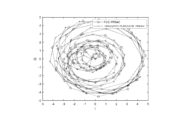
図3Aおよび図3Bは、FCC PRB#0と-180kHzだけシフトされたETSI PRB#0との各々についてのIQトレースを示す。図3Aおよび図3Bの各々について、100個のサンプルが、1.92MHzのサンプルレートを使用してプロットされた。
3A and 3B show IQ traces for
図3Aは、FCC PRB#0と-180kHzだけシフトされたETSI PRB#0との各々についてのIQトレースを示す。上記で説明されたように、NB-IoT-Uは、それぞれ、FCC規制およびETSI規制に従って、米国および欧州において利用可能にされることになる。米国におけるNB-IoT-Uは、フレーム構造タイプ3N1の設計に従うことになり、欧州における動作は、フレーム構造3N2の設計に従うことになる。既存の手法を用いると、フレーム構造3N1におけるNB-IoT-UアンカーセグメントPRB0、PRB1およびPRB2は、各PRBについてのOFDMシンボル開始位相がPRB番号に依存することになるので、整合された物理レイヤ波形を提供しないことになる。特に、NB-IoT-U PRB#0波形は、フレーム構造タイプ3N1および3N2にわたって整合されないことになる。
FIG. 3A shows IQ traces for each of
これの例が、図3Aに示されている。図3Aからわかるように、トレースは整合しない。帰結として、NPSS、NSSSおよびNPBCH波形は、米国と欧州とにおいて異なることになる。 An example of this is shown in Figure 3A. As can be seen in Figure 3A, the traces do not match. As a result, the NPSS, NSSS and NPBCH waveforms will be different in the US and Europe.
図3Bは、いくつかの実施形態による、位相補償が適用された、FCC PRB#0とETSI PRB#0との各々についてのIQトレースを示す。図2に関して上記で説明されたように、サブキャリア上のPRB依存位相回転を除去する位相補償を適用することによって、時間連続ベースバンド信号が生成されたとき、トレースは(図3Bに示されているように)完全に整合する。今や波形が整合されたので、NB-IoT-Uデバイスが、フレーム構造タイプ3N1とフレーム構造タイプ3N2との間のPRB#0上にマッピングされた波形の差により、受信されたPRB番号またはデバイスの地理的ロケーションに基づいてその受信機アルゴリズムを適応させる必要は、もはやない。
FIG. 3B shows IQ traces for each of
図4は、いくつかの実施形態による、ネットワークノードにおける方法のフローチャートである。より詳細には、図4は、無線通信システムにおけるネットワークノードによって実施される方法400のフローチャートである。いくつかの実施形態では、無線通信システムはNB-IoTであり得る。
FIG. 4 is a flowchart of a method at a network node, according to some embodiments. More particularly, FIG. 4 is a flowchart of a
方法400はステップ401において始まり、ネットワークノードは、サブキャリア上のPRB依存位相回転を除去する位相補償を適用することによって、時間連続ベースバンド信号を生成する。いくつかの実施形態では、時間連続ベースバンド信号は、NB-IoTキャリアのためのものであり得る。
ステップ402において、ネットワークノードは、生成された時間連続ベースバンド信号を無線周波数信号に変換する。ステップ403において、ネットワークノードは、無線インターフェース上で無線デバイスに無線周波数信号を送信する。いくつかの実施形態では、無線周波数信号は、未ライセンススペクトルにおいて送信され得る。
At
いくつかの実施形態では、ダウンリンクスロット中のOFDMシンボルlにおけるアンテナポートp上で送信される時間連続ベースバンド信号が、
![]()
0≦t<(NCP,l+N)×Tsである場合、

![]()
If 0≦t<(N CP,l +N)×T s ,
いくつかの実施形態では、位相補償はθk,lであり得る。いくつかの実施形態では、位相補償は、7OFDMシンボルの周期性を有し得る。いくつかの実施形態では、以下のうちの1つまたは複数が適用され得る:
![]()
![]()


![]()
![]()
![]()
![]()
![]()
![]()
![]()
![]()
図5は、いくつかの実施形態による、仮想化装置の概略ブロック図である。より詳細には、図5は、無線ネットワーク(たとえば、図2に示されている無線ネットワーク200)における装置500の概略ブロック図を示す。本装置は、ネットワークノード(たとえば、図2に示されているネットワークノード260)において実装され得る。装置500は、上記の図4に関して説明された例示的な方法、および、場合によっては、本明細書で開示される任意の他のプロセスまたは方法を行うように動作可能である。また、図4の方法は、必ずしも装置500のみによって行われるとは限らないことを理解されたい。その方法の少なくともいくつかの動作は、1つまたは複数の他のエンティティによって実施され得る。
FIG. 5 is a schematic block diagram of a virtualization device, according to some embodiments. More particularly, FIG. 5 shows a schematic block diagram of an
仮想装置500は、1つまたは複数のマイクロプロセッサまたはマイクロコントローラを含み得る、処理回路、ならびに、デジタル信号プロセッサ(DSP)、専用デジタル論理などを含み得る、他のデジタルハードウェアを備え得る。処理回路は、読取り専用メモリ(ROM)、ランダムアクセスメモリ、キャッシュメモリ、フラッシュメモリデバイス、光記憶デバイスなど、1つまたはいくつかのタイプのメモリを含み得るメモリに記憶されたプログラムコードを実行するように設定され得る。メモリに記憶されたプログラムコードは、いくつかの実施形態では、1つまたは複数の通信および/またはデータ通信プロトコルを実行するためのプログラム命令、ならびに本明細書で説明される技法のうちの1つまたは複数を行うための命令を含む。いくつかの実装形態では、処理回路は、受信ユニット502、決定ユニット504、通信ユニット506、および装置500の任意の他の好適なユニットに、本開示の1つまたは複数の実施形態による、対応する機能を実施させるために使用され得る。
図5に示されているように、装置500は、受信ユニット502と、決定ユニット504と、通信ユニット506とを含む。受信ユニット502は、装置500の受信機能を実施するように設定され得る。たとえば、受信ユニット502は、(たとえば、無線デバイスまたは別のネットワークノードから)任意の好適な情報を受信するように設定され得る。受信ユニット502は、受信機および/またはトランシーバを含み得る。受信ユニット502は、(無線または有線により)メッセージおよび/または信号を受信するように設定された回路を含み得る。特定の実施形態では、受信ユニット502は、受信されたメッセージおよび/または信号を決定ユニット504および/または装置500の任意の他の好適なユニットに通信し得る。受信ユニット502の機能は、いくつかの実施形態では、1つまたは複数の異なったユニットにおいて実施され得る。
As shown in FIG. 5,
決定ユニット504は、装置500の処理機能を実施し得る。いくつかの実施形態では、決定ユニット504は、NB-IoT-Uのために適応された位相補償項を備える時間連続NB-IoT-Uベースバンド信号を規定するように設定され得る。たとえば、決定ユニット504は、サブキャリア上のPRB依存位相回転を除去する位相補償を適用することによって、時間連続ベースバンド信号を生成するように設定され得る。いくつかの実施形態では、決定ユニット504は、図2および図3に関して上記で説明されたように、サブキャリア上のPRB依存位相回転を除去する位相補償を適用することによって、時間連続ベースバンド信号を生成するように設定され得る。決定ユニット504は、生成された時間連続ベースバンド信号を無線周波数信号に変換するように設定され得る。
決定ユニット504は、処理回路を含むか、または処理回路中に含まれ得る。決定ユニット504は、決定ユニット504および/または上記で説明された処理回路の機能のうちのいずれかを実施するように設定されたアナログおよび/またはデジタル回路を含み得る。決定ユニット504の機能は、いくつかの実施形態では、1つまたは複数の異なったユニットにおいて実施され得る。
通信ユニット506は、装置500の送信機能を実施するように設定され得る。たとえば、通信ユニット506は、(たとえば、無線デバイスおよび/またはネットワークノードに)メッセージまたは信号を送信するように設定され得る。たとえば、通信ユニット506は、無線インターフェース上で無線デバイスに無線周波数信号を送信するように設定され得る。いくつかの実施形態では、通信ユニット506は、未ライセンススペクトルにおいて無線周波数信号を送信するように設定され得る。
通信ユニット506は、送信機および/またはトランシーバを含み得る。通信ユニット506は、(たとえば、無線または有線手段を通して)メッセージおよび/または信号を送信するように設定された回路を含み得る。特定の実施形態では、通信ユニット506は、決定ユニット504または装置500の任意の他のユニットから送信のためのメッセージおよび/または信号を受信し得る。通信ユニット504の機能は、いくつかの実施形態では、1つまたは複数の異なったユニットにおいて実施され得る。
ユニットという用語は、エレクトロニクス、電気デバイス、および/または電子デバイスの分野での通常の意味を有し得、たとえば、本明細書で説明されるものなど、それぞれのタスク、プロシージャ、算出、出力、および/または表示機能を行うための、電気および/または電子回路、デバイス、モジュール、プロセッサ、メモリ、論理固体および/または個別デバイス、コンピュータプログラムまたは命令などを含み得る。 The term unit may have its ordinary meaning in the field of electronics, electrical devices, and/or electronic devices, e.g., for each task, procedure, calculation, output, and It may include electrical and/or electronic circuits, devices, modules, processors, memories, logic solid state and/or discrete devices, computer programs or instructions, etc., for performing display functions.
図6は、いくつかの実施形態による、UEの一実施形態を示す。本明細書で使用されるユーザ機器またはUEは、必ずしも、関連のあるデバイスを所有し、および/または動作させる人間のユーザという意味におけるユーザを有するとは限らない。代わりに、UEは、人間のユーザへの販売、または人間のユーザによる動作を意図されるが、特定の人間のユーザに関連しないことがあるか、または特定の人間のユーザに初めに関連しないことがある、デバイス(たとえば、スマートスプリンクラーコントローラ)を表し得る。代替的に、UEは、エンドユーザへの販売、またはエンドユーザによる動作を意図されないが、ユーザに関連するか、またはユーザの利益のために動作され得る、デバイス(たとえば、スマート電力計)を表し得る。UE600は、NB-IoT UE、マシン型通信(MTC)UE、および/または拡張MTC(eMTC)UEを含む、第3世代パートナーシッププロジェクト(3GPP)によって識別される任意のUEであり得る。図6に示されているUE600は、第3世代パートナーシッププロジェクト(3GPP)のGSM、UMTS、LTE、および/または5G規格など、3GPPによって公表された1つまたは複数の通信規格による通信のために設定されたWDの一例である。前述のように、WDおよびUEという用語は、互換的に使用され得る。したがって、図6はUEを示しているが、本明細書で説明される構成要素は、WDに等しく適用可能であり、その逆も同様である。
FIG. 6 illustrates one embodiment of a UE, according to some embodiments. User equipment or UE as used herein does not necessarily have a user in the sense of a human user who owns and/or operates the associated device. Alternatively, the UE is intended for sale to or operation by human users, but may not be associated with, or initially associated with, a particular human user. may represent a device (e.g., a smart sprinkler controller). Alternatively, the UE represents a device (e.g., a smart power meter) that is not intended for sale to or operation by an end user, but that may be associated with or operated for the benefit of the user. obtain.
図6では、UE600は、入出力インターフェース605、無線周波数(RF)インターフェース609、ネットワーク接続インターフェース611、ランダムアクセスメモリ(RAM)617と読取り専用メモリ(ROM)619と記憶媒体621などとを含むメモリ615、通信サブシステム631、電源633、および/または他の構成要素、あるいはそれらの任意の組合せに動作可能に接続された、処理回路601を含む。記憶媒体621は、オペレーティングシステム623と、アプリケーションプログラム625と、データ627とを含む。他の実施形態では、記憶媒体621は、他の同様のタイプの情報を含み得る。いくつかのUEは、図6に示されている構成要素のすべてを利用するか、またはそれらの構成要素のサブセットのみを利用し得る。構成要素間の統合のレベルは、UEごとに変動し得る。さらに、いくつかのUEは、複数のプロセッサ、メモリ、トランシーバ、送信機、受信機など、構成要素の複数のインスタンスを含んでいることがある。
In FIG. 6, the
図6では、処理回路601は、コンピュータ命令およびデータを処理するように設定され得る。処理回路601は、(たとえば、ディスクリート論理、FPGA、ASICなどにおける)1つまたは複数のハードウェア実装状態マシンなど、マシン可読コンピュータプログラムとしてメモリに記憶されたマシン命令を実行するように動作可能な任意の逐次状態マシン、適切なファームウェアと一緒のプログラマブル論理、適切なソフトウェアと一緒のマイクロプロセッサまたはデジタル信号プロセッサ(DSP)など、1つまたは複数のプログラム内蔵、汎用プロセッサ、あるいは上記の任意の組合せを実装するように設定され得る。たとえば、処理回路601は、2つの中央処理ユニット(CPU)を含み得る。データは、コンピュータによる使用に好適な形態での情報であり得る。
In FIG. 6,
図示された実施形態では、入出力インターフェース605は、入力デバイス、出力デバイス、または入出力デバイスに通信インターフェースを提供するように設定され得る。UE600は、入出力インターフェース605を介して出力デバイスを使用するように設定され得る。出力デバイスは、入力デバイスと同じタイプのインターフェースポートを使用し得る。たとえば、UE600への入力およびUE600からの出力を提供するために、USBポートが使用され得る。出力デバイスは、スピーカー、サウンドカード、ビデオカード、ディスプレイ、モニタ、プリンタ、アクチュエータ、エミッタ、スマートカード、別の出力デバイス、またはそれらの任意の組合せであり得る。UE600は、ユーザがUE600に情報をキャプチャすることを可能にするために、入出力インターフェース605を介して入力デバイスを使用するように設定され得る。入力デバイスは、タッチセンシティブまたはプレゼンスセンシティブディスプレイ、カメラ(たとえば、デジタルカメラ、デジタルビデオカメラ、ウェブカメラなど)、マイクロフォン、センサー、マウス、トラックボール、方向パッド、トラックパッド、スクロールホイール、スマートカードなどを含み得る。プレゼンスセンシティブディスプレイは、ユーザからの入力を検知するための容量性または抵抗性タッチセンサーを含み得る。センサーは、たとえば、加速度計、ジャイロスコープ、チルトセンサー、力センサー、磁力計、光センサー、近接度センサー、別の同様のセンサー、またはそれらの任意の組合せであり得る。たとえば、入力デバイスは、加速度計、磁力計、デジタルカメラ、マイクロフォン、および光センサーであり得る。
In the illustrated embodiment, input/
図6では、RFインターフェース609は、送信機、受信機、およびアンテナなど、RF構成要素に通信インターフェースを提供するように設定され得る。ネットワーク接続インターフェース611は、ネットワーク643aに通信インターフェースを提供するように設定され得る。ネットワーク643aは、ローカルエリアネットワーク(LAN)、ワイドエリアネットワーク(WAN)、コンピュータネットワーク、無線ネットワーク、通信ネットワーク、別の同様のネットワークまたはそれらの任意の組合せなど、有線および/または無線ネットワークを包含し得る。たとえば、ネットワーク643aは、Wi-Fiネットワークを備え得る。ネットワーク接続インターフェース611は、イーサネット、TCP/IP、SONET、ATMなど、1つまたは複数の通信プロトコルに従って通信ネットワーク上で1つまたは複数の他のデバイスと通信するために使用される、受信機および送信機インターフェースを含むように設定され得る。ネットワーク接続インターフェース611は、通信ネットワークリンク(たとえば、光学的、電気的など)に適した受信機および送信機機能を実装し得る。送信機および受信機機能は、回路構成要素、ソフトウェアまたはファームウェアを共有し得るか、あるいは、代替的に、別個に実装され得る。
In FIG. 6,
RAM617は、オペレーティングシステム、アプリケーションプログラム、およびデバイスドライバなど、ソフトウェアプログラムの実行中に、データまたはコンピュータ命令の記憶またはキャッシングを提供するために、バス602を介して処理回路601にインターフェースするように設定され得る。ROM619は、処理回路601にコンピュータ命令またはデータを提供するように設定され得る。たとえば、ROM619は、不揮発性メモリに記憶される、基本入出力(I/O)、起動、またはキーボードからのキーストロークの受信など、基本システム機能のための、不変低レベルシステムコードまたはデータを記憶するように設定され得る。記憶媒体621は、RAM、ROM、プログラマブル読取り専用メモリ(PROM)、消去可能プログラマブル読取り専用メモリ(EPROM)、電気的消去可能プログラマブル読取り専用メモリ(EEPROM)、磁気ディスク、光ディスク、フロッピーディスク、ハードディスク、リムーバブルカートリッジ、またはフラッシュドライブなど、メモリを含むように設定され得る。一例では、記憶媒体621は、オペレーティングシステム623と、ウェブブラウザアプリケーション、ウィジェットまたはガジェットエンジン、あるいは別のアプリケーションなどのアプリケーションプログラム625と、データファイル627とを含むように設定され得る。記憶媒体621は、UE600による使用のために、多様な様々なオペレーティングシステムまたはオペレーティングシステムの組合せのうちのいずれかを記憶し得る。
記憶媒体621は、独立ディスクの冗長アレイ(RAID)、フロッピーディスクドライブ、フラッシュメモリ、USBフラッシュドライブ、外部ハードディスクドライブ、サムドライブ、ペンドライブ、キードライブ、高密度デジタル多用途ディスク(HD-DVD)光ディスクドライブ、内蔵ハードディスクドライブ、Blu-Ray光ディスクドライブ、ホログラフィックデジタルデータ記憶(HDDS)光ディスクドライブ、外部ミニデュアルインラインメモリモジュール(DIMM)、シンクロナスダイナミックランダムアクセスメモリ(SDRAM)、外部マイクロDIMM SDRAM、加入者識別モジュールまたはリムーバブルユーザ識別情報(SIM/RUIM)モジュールなどのスマートカードメモリ、他のメモリ、あるいはそれらの任意の組合せなど、いくつかの物理ドライブユニットを含むように設定され得る。記憶媒体621は、UE600が、一時的または非一時的メモリ媒体に記憶されたコンピュータ実行可能命令、アプリケーションプログラムなどにアクセスすること、データをオフロードすること、あるいはデータをアップロードすることを可能にし得る。通信システムを利用する製造品などの製造品は、記憶媒体621中に有形に具現され得、記憶媒体621はデバイス可読媒体を備え得る。
The storage medium 621 can be a redundant array of independent disks (RAID), floppy disk drive, flash memory, USB flash drive, external hard disk drive, thumb drive, pen drive, key drive, high density digital versatile disk (HD-DVD) optical disk. Drive, Internal Hard Disk Drive, Blu-Ray Optical Disk Drive, Holographic Digital Data Storage (HDDS) Optical Disk Drive, External Mini Dual Inline Memory Module (DIMM), Synchronous Dynamic Random Access Memory (SDRAM), External Micro DIMM SDRAM, Subscriber It may be configured to include several physical drive units, such as smart card memory, other memory, or any combination thereof, such as an identification module or removable user identity (SIM/RUIM) module. Storage medium 621 may enable
図6では、処理回路601は、通信サブシステム631を使用してネットワーク643bと通信するように設定され得る。ネットワーク643aとネットワーク643bとは、同じ1つまたは複数のネットワークまたは異なる1つまたは複数のネットワークであり得る。通信サブシステム631は、ネットワーク643bと通信するために使用される1つまたは複数のトランシーバを含むように設定され得る。たとえば、通信サブシステム631は、IEEE802.11、CDMA、WCDMA、GSM、LTE、UTRAN、WiMaxなど、1つまたは複数の通信プロトコルに従って、無線アクセスネットワーク(RAN)の別のWD、UE、または基地局など、無線通信が可能な別のデバイスの1つまたは複数のリモートトランシーバと通信するために使用される、1つまたは複数のトランシーバを含むように設定され得る。各トランシーバは、RANリンク(たとえば、周波数割り当てなど)に適した送信機機能または受信機機能をそれぞれ実装するための、送信機633および/または受信機635を含み得る。さらに、各トランシーバの送信機633および受信機635は、回路構成要素、ソフトウェアまたはファームウェアを共有し得るか、あるいは、代替的に、別個に実装され得る。
In FIG. 6,
示されている実施形態では、通信サブシステム631の通信機能は、データ通信、ボイス通信、マルチメディア通信、Bluetoothなどの短距離通信、ニアフィールド通信、ロケーションを決定するための全地球測位システム(GPS)の使用などのロケーションベース通信、別の同様の通信機能、またはそれらの任意の組合せを含み得る。たとえば、通信サブシステム631は、セルラ通信と、Wi-Fi通信と、Bluetooth通信と、GPS通信とを含み得る。ネットワーク643bは、ローカルエリアネットワーク(LAN)、ワイドエリアネットワーク(WAN)、コンピュータネットワーク、無線ネットワーク、通信ネットワーク、別の同様のネットワークまたはそれらの任意の組合せなど、有線および/または無線ネットワークを包含し得る。たとえば、ネットワーク643bは、セルラネットワーク、Wi-Fiネットワーク、および/またはニアフィールドネットワークであり得る。電源613は、UE600の構成要素に交流(AC)または直流(DC)電力を提供するように設定され得る。
In the embodiment shown, the communications functionality of communications subsystem 631 includes data communications, voice communications, multimedia communications, short range communications such as Bluetooth, near field communications, and Global Positioning System (GPS) for determining location. ), other similar communication capabilities, or any combination thereof. For example, communications subsystem 631 may include cellular communications, Wi-Fi communications, Bluetooth communications, and GPS communications. Network 643b may include wired and/or wireless networks, such as a local area network (LAN), wide area network (WAN), computer network, wireless network, communication network, another similar network, or any combination thereof. . For example, network 643b may be a cellular network, a Wi-Fi network, and/or a near-field network.
本明細書で説明される特徴、利益および/または機能は、UE600の構成要素のうちの1つにおいて実装されるか、またはUE600の複数の構成要素にわたって分割され得る。さらに、本明細書で説明される特徴、利益、および/または機能は、ハードウェア、ソフトウェアまたはファームウェアの任意の組合せで実装され得る。一例では、通信サブシステム631は、本明細書で説明される構成要素のうちのいずれかを含むように設定され得る。さらに、処理回路601は、バス602上でそのような構成要素のうちのいずれかと通信するように設定され得る。別の例では、そのような構成要素のうちのいずれかは、処理回路601によって実行されたとき、本明細書で説明される対応する機能を実施する、メモリに記憶されたプログラム命令によって表され得る。別の例では、そのような構成要素のうちのいずれかの機能は、処理回路601と通信サブシステム631との間で分割され得る。別の例では、そのような構成要素のうちのいずれかの非計算集約的機能が、ソフトウェアまたはファームウェアで実装され得、計算集約的機能がハードウェアで実装され得る。
The features, benefits and/or functionality described herein may be implemented in one of the components of
図7は、いくつかの実施形態による、仮想化環境を示す概略ブロック図である。より詳細には、図7は、いくつかの実施形態によって実装される機能が仮想化され得る、仮想化環境700を示す概略ブロック図である。本コンテキストでは、仮想化することは、ハードウェアプラットフォーム、記憶デバイスおよびネットワーキングリソースを仮想化することを含み得る、装置またはデバイスの仮想バージョンを作成することを意味する。本明細書で使用される仮想化は、ノード(たとえば、仮想化された基地局または仮想化された無線アクセスノード)に、あるいはデバイス(たとえば、UE、無線デバイスまたは任意の他のタイプの通信デバイス)またはそのデバイスの構成要素に適用され得、機能の少なくとも一部分が、(たとえば、1つまたは複数のネットワークにおいて1つまたは複数の物理処理ノード上で実行する、1つまたは複数のアプリケーション、構成要素、機能、仮想マシンまたはコンテナを介して)1つまたは複数の仮想構成要素として実装される、実装形態に関する。
FIG. 7 is a schematic block diagram illustrating a virtualized environment, according to some embodiments. More particularly, FIG. 7 is a schematic block diagram illustrating a
いくつかの実施形態では、本明細書で説明される機能の一部または全部は、ハードウェアノード730のうちの1つまたは複数によってホストされる1つまたは複数の仮想環境700において実装される1つまたは複数の仮想マシンによって実行される、仮想構成要素として実装され得る。さらに、仮想ノードが、無線アクセスノードではないか、または無線コネクティビティ(たとえば、コアネットワークノード)を必要としない実施形態では、ネットワークノードは完全に仮想化され得る。
In some embodiments, some or all of the functionality described herein is implemented in one or more
機能は、本明細書で開示される実施形態のうちのいくつかの特徴、機能、および/または利益のうちのいくつかを実装するように動作可能な、(代替的に、ソフトウェアインスタンス、仮想アプライアンス、ネットワーク機能、仮想ノード、仮想ネットワーク機能などと呼ばれることがある)1つまたは複数のアプリケーション720によって実装され得る。アプリケーション720は、処理回路760とメモリ790とを備えるハードウェア730を提供する、仮想化環境700において稼働される。メモリ790は、処理回路760によって実行可能な命令795を含んでおり、それにより、アプリケーション720は、本明細書で開示される特徴、利益、および/または機能のうちの1つまたは複数を提供するように動作可能である。
A feature may include (alternatively, a software instance, virtual appliance) operable to implement some of the features, functionality, and/or benefits of the embodiments disclosed herein. , network function, virtual node, virtual network function, etc.).
仮想化環境700は、1つまたは複数のプロセッサのセットまたは処理回路760を備える、汎用または専用のネットワークハードウェアデバイス730を備え、1つまたは複数のプロセッサのセットまたは処理回路760は、商用オフザシェルフ(COTS)プロセッサ、専用の特定用途向け集積回路(ASIC)、あるいは、デジタルもしくはアナログハードウェア構成要素または専用プロセッサを含む任意の他のタイプの処理回路であり得る。各ハードウェアデバイスはメモリ790-1を備え得、メモリ790-1は、処理回路760によって実行される命令795またはソフトウェアを一時的に記憶するための非永続的メモリであり得る。各ハードウェアデバイスは、ネットワークインターフェースカードとしても知られる、1つまたは複数のネットワークインターフェースコントローラ(NIC)770を備え得、ネットワークインターフェースコントローラ(NIC)770は物理ネットワークインターフェース780を含む。各ハードウェアデバイスは、処理回路760によって実行可能なソフトウェア795および/または命令を記憶した、非一時的、永続的、マシン可読記憶媒体790-2をも含み得る。ソフトウェア795は、1つまたは複数の(ハイパーバイザとも呼ばれる)仮想化レイヤ750をインスタンス化するためのソフトウェア、仮想マシン740を実行するためのソフトウェア、ならびに、それが、本明細書で説明されるいくつかの実施形態との関係において説明される機能、特徴および/または利益を実行することを可能にする、ソフトウェアを含む、任意のタイプのソフトウェアを含み得る。
仮想マシン740は、仮想処理、仮想メモリ、仮想ネットワーキングまたはインターフェース、および仮想ストレージを備え、対応する仮想化レイヤ750またはハイパーバイザによって稼働され得る。仮想アプライアンス720の事例の異なる実施形態が、仮想マシン740のうちの1つまたは複数上で実装され得、実装は異なるやり方で行われ得る。
動作中に、処理回路760は、ソフトウェア795を実行してハイパーバイザまたは仮想化レイヤ750をインスタンス化し、ハイパーバイザまたは仮想化レイヤ750は、時々、仮想マシンモニタ(VMM)と呼ばれることがある。仮想化レイヤ750は、仮想マシン740に、ネットワーキングハードウェアのように見える仮想動作プラットフォームを提示し得る。
In operation, processing circuitry 760 executes
図7に示されているように、ハードウェア730は、一般的なまたは特定の構成要素をもつスタンドアロンネットワークノードであり得る。ハードウェア730は、アンテナ7225を備え得、仮想化を介していくつかの機能を実装し得る。代替的に、ハードウェア730は、多くのハードウェアノードが協働し、特に、アプリケーション720のライフサイクル管理を監督する、管理およびオーケストレーション(MANO)7100を介して管理される、(たとえば、データセンタまたは顧客構内機器(CPE)の場合のような)ハードウェアのより大きいクラスタの一部であり得る。
As shown in FIG. 7,
ハードウェアの仮想化は、いくつかのコンテキストにおいて、ネットワーク機能仮想化(NFV)と呼ばれる。NFVは、多くのネットワーク機器タイプを、データセンタおよび顧客構内機器中に位置し得る、業界標準高ボリュームサーバハードウェア、物理スイッチ、および物理ストレージ上にコンソリデートするために使用され得る。 Hardware virtualization is referred to in some contexts as network functions virtualization (NFV). NFV can be used to consolidate many network equipment types onto industry standard high volume server hardware, physical switches, and physical storage that can be located in data centers and customer premises equipment.
NFVのコンテキストでは、仮想マシン740は、プログラムを、それらのプログラムが、物理的な仮想化されていないマシン上で実行しているかのように稼働する、物理マシンのソフトウェア実装形態であり得る。仮想マシン740の各々と、その仮想マシンに専用のハードウェアであろうと、および/またはその仮想マシンによって仮想マシン740のうちの他の仮想マシンと共有されるハードウェアであろうと、その仮想マシンを実行するハードウェア730のその一部とは、別個の仮想ネットワークエレメント(VNE)を形成する。
In the context of NFV,
さらにNFVのコンテキストでは、仮想ネットワーク機能(VNF)は、ハードウェアネットワーキングインフラストラクチャ730の上の1つまたは複数の仮想マシン740において稼働する特定のネットワーク機能をハンドリングすることを担当し、図7中のアプリケーション720に対応する。
Further in the context of NFV, a virtual network function (VNF) is responsible for handling specific network functions running in one or more
いくつかの実施形態では、各々、1つまたは複数の送信機7220と1つまたは複数の受信機7210とを含む、1つまたは複数の無線ユニット7200は、1つまたは複数のアンテナ7225に結合され得る。無線ユニット7200は、1つまたは複数の適切なネットワークインターフェースを介してハードウェアノード730と直接通信し得、無線アクセスノードまたは基地局など、無線能力をもつ仮想ノードを提供するために仮想構成要素と組み合わせて使用され得る。
In some embodiments, one or
いくつかの実施形態では、何らかのシグナリングが、ハードウェアノード730と無線ユニット7200との間の通信のために代替的に使用され得る制御システム7230を使用して、実現され得る。
In some embodiments, some signaling may be accomplished using
図8は、いくつかの実施形態による、中間ネットワークを介してホストコンピュータに接続された例示的な通信ネットワークを示す。図8を参照すると、一実施形態によれば、通信システムが、無線アクセスネットワークなどのアクセスネットワーク811とコアネットワーク814とを備える、3GPPタイプセルラネットワークなどの通信ネットワーク810を含む。アクセスネットワーク811は、NB、eNB、gNBまたは他のタイプの無線アクセスポイントなど、複数の基地局812a、812b、812cを備え、各々が、対応するカバレッジエリア813a、813b、813cを規定する。各基地局812a、812b、812cは、有線接続または無線接続815上でコアネットワーク814に接続可能である。カバレッジエリア813c中に位置する第1のUE891が、対応する基地局812cに無線で接続するか、または対応する基地局812cによってページングされるように設定される。カバレッジエリア813a中の第2のUE892が、対応する基地局812aに無線で接続可能である。この例では複数のUE891、892が示されているが、開示される実施形態は、唯一のUEがカバレッジエリア中にある状況、または、唯一のUEが、対応する基地局812に接続している状況に等しく適用可能である。
FIG. 8 illustrates an example communications network connected to a host computer via an intermediate network, according to some embodiments. Referring to FIG. 8, according to one embodiment, a communication system includes a
通信ネットワーク810は、それ自体、ホストコンピュータ830に接続され、ホストコンピュータ830は、スタンドアロンサーバ、クラウド実装サーバ、分散サーバのハードウェアおよび/またはソフトウェアにおいて、あるいはサーバファーム中の処理リソースとして具現され得る。ホストコンピュータ830は、サービスプロバイダの所有または制御下にあり得、あるいはサービスプロバイダによってまたはサービスプロバイダに代わって動作され得る。通信ネットワーク810とホストコンピュータ830との間の接続821および822は、コアネットワーク814からホストコンピュータ830に直接延び得るか、または随意の中間ネットワーク820を介して進み得る。中間ネットワーク820は、パブリックネットワーク、プライベートネットワーク、またはホストされたネットワークのうちの1つ、またはそれらのうちの2つ以上の組合せであり得、中間ネットワーク820は、もしあれば、バックボーンネットワークまたはインターネットであり得、特に、中間ネットワーク820は、2つまたはそれ以上のサブネットワーク(図示せず)を備え得る。
The
図8の通信システムは全体として、接続されたUE891、892とホストコンピュータ830との間のコネクティビティを可能にする。コネクティビティは、オーバーザトップ(OTT)接続850として説明され得る。ホストコンピュータ830および接続されたUE891、892は、アクセスネットワーク811、コアネットワーク814、任意の中間ネットワーク820、および考えられるさらなるインフラストラクチャ(図示せず)を媒介として使用して、OTT接続850を介して、データおよび/またはシグナリングを通信するように設定される。OTT接続850は、OTT接続850が通過する、参加する通信デバイスが、アップリンクおよびダウンリンク通信のルーティングに気づいていないという意味で、透過的であり得る。たとえば、基地局812は、接続されたUE891にフォワーディング(たとえば、ハンドオーバ)されるべき、ホストコンピュータ830から発生したデータを伴う着信ダウンリンク通信の過去のルーティングについて、通知されないことがあるかまたは通知される必要がない。同様に、基地局812は、UE891から発生してホストコンピュータ830に向かう発信アップリンク通信の将来のルーティングに気づいている必要がない。
The communication system of FIG. 8 as a whole enables connectivity between connected
図9は、いくつかの実施形態による、部分的無線接続上で基地局を介してUEと通信するホストコンピュータの一例を示す。次に、一実施形態による、前の段落において説明されたUE、基地局およびホストコンピュータの例示的な実装形態が、図9を参照しながら説明される。通信システム900では、ホストコンピュータ910が、通信システム900の異なる通信デバイスのインターフェースとの有線接続または無線接続をセットアップおよび維持するように設定された通信インターフェース916を含む、ハードウェア915を備える。ホストコンピュータ910は、記憶能力および/または処理能力を有し得る、処理回路918をさらに備える。特に、処理回路918は、1つまたは複数のプログラマブルプロセッサ、特定用途向け集積回路、フィールドプログラマブルゲートアレイ、または、命令を実行するように適応されたこれらの組合せ(図示せず)を備え得る。ホストコンピュータ910は、ホストコンピュータ910に記憶されるかまたはホストコンピュータ910によってアクセス可能であり、処理回路918によって実行可能である、ソフトウェア911をさらに備える。ソフトウェア911はホストアプリケーション912を含む。ホストアプリケーション912は、UE930およびホストコンピュータ910において終端するOTT接続950を介して接続するUE930など、リモートユーザにサービスを提供するように動作可能であり得る。リモートユーザにサービスを提供する際に、ホストアプリケーション912は、OTT接続950を使用して送信されるユーザデータを提供し得る。
FIG. 9 illustrates an example of a host computer communicating with a UE via a base station over a partial wireless connection, according to some embodiments. An example implementation of the UE, base station and host computer described in the previous paragraph, according to one embodiment, will now be described with reference to FIG. 9. In
通信システム900は、通信システム中に提供される基地局920をさらに含み、基地局920は、基地局920がホストコンピュータ910およびUE930と通信することを可能にするハードウェア925を備える。ハードウェア925は、通信システム900の異なる通信デバイスのインターフェースとの有線接続または無線接続をセットアップおよび維持するための通信インターフェース926、ならびに基地局920によってサーブされるカバレッジエリア(図9に図示せず)中に位置するUE930との少なくとも無線接続970をセットアップおよび維持するための無線インターフェース927を含み得る。通信インターフェース926は、ホストコンピュータ910への接続960を容易にするように設定され得る。接続960は直接であり得るか、あるいは、接続960は、通信システムのコアネットワーク(図9に図示せず)を、および/または通信システムの外部の1つまたは複数の中間ネットワークを通過し得る。図示の実施形態では、基地局920のハードウェア925は、処理回路928をさらに含み、処理回路928は、1つまたは複数のプログラマブルプロセッサ、特定用途向け集積回路、フィールドプログラマブルゲートアレイ、または、命令を実行するように適応されたこれらの組合せ(図示せず)を備え得る。基地局920は、内部的に記憶されるかまたは外部接続を介してアクセス可能なソフトウェア921をさらに有する。
通信システム900は、すでに言及されたUE930をさらに含む。UE930のハードウェア935は、UE930が現在位置するカバレッジエリアをサーブする基地局との無線接続970をセットアップおよび維持するように設定された、無線インターフェース937を含み得る。UE930のハードウェア935は、処理回路938をさらに含み、処理回路938は、1つまたは複数のプログラマブルプロセッサ、特定用途向け集積回路、フィールドプログラマブルゲートアレイ、または、命令を実行するように適応されたこれらの組合せ(図示せず)を備え得る。UE930は、UE930に記憶されるかまたはUE930によってアクセス可能であり、処理回路938によって実行可能である、ソフトウェア931をさらに備える。ソフトウェア931はクライアントアプリケーション932を含む。クライアントアプリケーション932は、ホストコンピュータ910のサポートのもとに、UE930を介して人間のまたは人間でないユーザにサービスを提供するように動作可能であり得る。ホストコンピュータ910では、実行しているホストアプリケーション912は、UE930およびホストコンピュータ910において終端するOTT接続950を介して、実行しているクライアントアプリケーション932と通信し得る。ユーザにサービスを提供する際に、クライアントアプリケーション932は、ホストアプリケーション912から要求データを受信し、要求データに応答してユーザデータを提供し得る。OTT接続950は、要求データとユーザデータの両方を転送し得る。クライアントアプリケーション932は、クライアントアプリケーション932が提供するユーザデータを生成するためにユーザと対話し得る。
図9に示されているホストコンピュータ910、基地局920およびUE930は、それぞれ、図8のホストコンピュータ830、基地局812a、812b、812cのうちの1つ、およびUE891、892のうちの1つと同様または同等であり得ることに留意されたい。つまり、これらのエンティティの内部の働きは、図9に示されているようなものであり得、別個に、周囲のネットワークトポロジーは、図8のものであり得る。
The host computer 910, base station 920, and
図9では、OTT接続950は、仲介デバイスとこれらのデバイスを介したメッセージの正確なルーティングとへの明示的言及なしに、基地局920を介したホストコンピュータ910とUE930との間の通信を示すために抽象的に描かれている。ネットワークインフラストラクチャが、ルーティングを決定し得、ネットワークインフラストラクチャは、UE930からまたはホストコンピュータ910を動作させるサービスプロバイダから、またはその両方からルーティングを隠すように設定され得る。OTT接続950がアクティブである間、ネットワークインフラストラクチャは、さらに、ネットワークインフラストラクチャが(たとえば、ネットワークの負荷分散考慮または再設定に基づいて)ルーティングを動的に変更する判断を行い得る。
In FIG. 9,
UE930と基地局920との間の無線接続970は、本開示全体にわたって説明される実施形態の教示に従う。様々な実施形態のうちの1つまたは複数は、無線接続970が最後のセグメントを形成するOTT接続950を使用して、UE930に提供されるOTTサービスの性能を改善する。
The
1つまたは複数の実施形態が改善する、データレート、レイテンシおよび他のファクタを監視する目的での、測定プロシージャが提供され得る。測定結果の変動に応答して、ホストコンピュータ910とUE930との間のOTT接続950を再設定するための随意のネットワーク機能がさらにあり得る。測定プロシージャおよび/またはOTT接続950を再設定するためのネットワーク機能は、ホストコンピュータ910のソフトウェア911およびハードウェア915でまたはUE930のソフトウェア931およびハードウェア935で、またはその両方で実装され得る。実施形態では、OTT接続950が通過する通信デバイスにおいてまたはそれに関連して、センサー(図示せず)が展開され得、センサーは、上記で例示された監視された量の値を供給すること、またはソフトウェア911、931が監視された量を算出または推定し得る他の物理量の値を供給することによって、測定プロシージャに参加し得る。OTT接続950の再設定は、メッセージフォーマット、再送信セッティング、好ましいルーティングなどを含み得、再設定は、基地局920に影響を及ぼす必要がなく、再設定は、基地局920に知られていないかまたは知覚不可能であり得る。そのようなプロシージャおよび機能は、当技術分野において知られ、実践され得る。いくつかの実施形態では、測定は、スループット、伝搬時間、レイテンシなどのホストコンピュータ910の測定を容易にするプロプライエタリUEシグナリングを伴い得る。測定は、ソフトウェア911および931が、ソフトウェア911および931が伝搬時間、エラーなどを監視する間にOTT接続950を使用して、メッセージ、特に空のまたは「ダミー」メッセージが送信されることを引き起こすことにおいて、実装され得る。
Measurement procedures may be provided for the purpose of monitoring data rates, latency, and other factors that one or more embodiments improve. There may further be an optional network function for reconfiguring the
図10は、いくつかの実施形態による、通信システムにおいて実装される方法のフローチャートである。通信システムは、図8および図9を参照しながら説明されたものであり得る、ホストコンピュータと基地局とUEとを含む。本開示の簡単のために、図10への図面参照のみがこのセクションに含まれる。ステップ1010において、ホストコンピュータはユーザデータを提供する。ステップ1010の(随意であり得る)サブステップ1011において、ホストコンピュータは、ホストアプリケーションを実行することによって、ユーザデータを提供する。ステップ1020において、ホストコンピュータは、UEにユーザデータを搬送する送信を始動する。(随意であり得る)ステップ1030において、基地局は、本開示全体にわたって説明される実施形態の教示に従って、ホストコンピュータが始動した送信において搬送されたユーザデータをUEに送信する。(また、随意であり得る)ステップ1040において、UEは、ホストコンピュータによって実行されるホストアプリケーションに関連するクライアントアプリケーションを実行する。
FIG. 10 is a flowchart of a method implemented in a communication system, according to some embodiments. The communication system includes a host computer, a base station, and a UE, which may be as described with reference to FIGS. 8 and 9. For simplicity of this disclosure, only drawing references to FIG. 10 are included in this section. At
図11は、いくつかの実施形態による、通信システムにおいて実装される方法のフローチャートである。通信システムは、図8および図9を参照しながら説明されたものであり得る、ホストコンピュータと基地局とUEとを含む。本開示の簡単のために、図11への図面参照のみがこのセクションに含まれる。方法のステップ1110において、ホストコンピュータはユーザデータを提供する。随意のサブステップ(図示せず)において、ホストコンピュータは、ホストアプリケーションを実行することによって、ユーザデータを提供する。ステップ1120において、ホストコンピュータは、UEにユーザデータを搬送する送信を始動する。送信は、本開示全体にわたって説明される実施形態の教示に従って、基地局を介して進み得る。(随意であり得る)ステップ1130において、UEは、送信において搬送されたユーザデータを受信する。
FIG. 11 is a flowchart of a method implemented in a communication system, according to some embodiments. The communication system includes a host computer, a base station, and a UE, which may be as described with reference to FIGS. 8 and 9. For simplicity of the disclosure, only drawing references to FIG. 11 are included in this section. In
図12は、いくつかの実施形態による、通信システムにおいて実装される方法のフローチャートである。通信システムは、図8および図9を参照しながら説明されたものであり得る、ホストコンピュータと基地局とUEとを含む。本開示の簡単のために、図12への図面参照のみがこのセクションに含まれる。(随意であり得る)ステップ1210において、UEは、ホストコンピュータによって提供された入力データを受信する。追加または代替として、ステップ1220において、UEはユーザデータを提供する。ステップ1220の(随意であり得る)サブステップ1221において、UEは、クライアントアプリケーションを実行することによって、ユーザデータを提供する。ステップ1210の(随意であり得る)サブステップ1211において、UEは、ホストコンピュータによって提供された受信された入力データに反応してユーザデータを提供する、クライアントアプリケーションを実行する。ユーザデータを提供する際に、実行されたクライアントアプリケーションは、ユーザから受信されたユーザ入力をさらに考慮し得る。ユーザデータが提供された特定の様式にかかわらず、UEは、(随意であり得る)サブステップ1230において、ホストコンピュータへのユーザデータの送信を始動する。方法のステップ1240において、ホストコンピュータは、本開示全体にわたって説明される実施形態の教示に従って、UEから送信されたユーザデータを受信する。
FIG. 12 is a flowchart of a method implemented in a communication system, according to some embodiments. The communication system includes a host computer, a base station, and a UE, which may be as described with reference to FIGS. 8 and 9. For simplicity of the disclosure, only drawing references to FIG. 12 are included in this section. At step 1210 (which may be optional), the UE receives input data provided by the host computer. Additionally or alternatively, in
図13は、いくつかの実施形態による、通信システムにおいて実装される方法のフローチャートである。通信システムは、図8および図9を参照しながら説明されたものであり得る、ホストコンピュータと基地局とUEとを含む。本開示の簡単のために、図13への図面参照のみがこのセクションに含まれる。(随意であり得る)ステップ1310において、本開示全体にわたって説明される実施形態の教示に従って、基地局は、UEからユーザデータを受信する。(随意であり得る)ステップ1320において、基地局は、ホストコンピュータへの、受信されたユーザデータの送信を始動する。(随意であり得る)ステップ1330において、ホストコンピュータは、基地局によって始動された送信において搬送されたユーザデータを受信する。 FIG. 13 is a flowchart of a method implemented in a communication system, according to some embodiments. The communication system includes a host computer, a base station, and a UE, which may be as described with reference to FIGS. 8 and 9. For simplicity of the disclosure, only drawing references to FIG. 13 are included in this section. At step 1310 (which may be optional), the base station receives user data from the UE in accordance with the teachings of embodiments described throughout this disclosure. At step 1320 (which may be optional), the base station initiates transmission of the received user data to the host computer. At step 1330 (which may be optional), the host computer receives user data carried in a base station initiated transmission.
いくつかの実施形態では、コンピュータプログラム、コンピュータプログラム製品またはコンピュータ可読記憶媒体は、コンピュータ上で実行されたとき、本明細書で開示される実施形態のうちのいずれかを実施する命令を備える。さらなる例では、命令は、信号またはキャリア上で搬送され、それはコンピュータ上で実行可能であり、実行されたとき、本明細書で開示される実施形態のうちのいずれかを実施する。 In some embodiments, a computer program, computer program product, or computer readable storage medium comprises instructions that, when executed on a computer, implement any of the embodiments disclosed herein. In a further example, instructions are carried on a signal or carrier that are executable on a computer and, when executed, implement any of the embodiments disclosed herein.
本開示の範囲から逸脱することなく、本明細書で説明されるシステムおよび装置に対して修正、追加、または省略が行われ得る。システムおよび装置の構成要素は、統合または分離され得る。その上、システムおよび装置の動作は、より多数の、より少数の、または他の構成要素によって実施され得る。さらに、システムおよび装置の動作は、ソフトウェア、ハードウェア、および/または他の論理を含む任意の好適な論理を使用して実施され得る。本明細書で使用される「各々」は、セットの各メンバーまたはセットのサブセットの各メンバーを指す。 Modifications, additions, or omissions may be made to the systems and apparatus described herein without departing from the scope of this disclosure. System and device components may be integrated or separated. Moreover, the operations of the systems and devices may be performed by more, fewer, or other components. Additionally, operations of the systems and devices may be implemented using any suitable logic, including software, hardware, and/or other logic. As used herein, "each" refers to each member of a set or each member of a subset of a set.
本開示の範囲から逸脱することなく、本明細書で説明される方法に対して修正、追加、または省略が行われ得る。本方法は、より多数の、より少数の、または他のステップを含み得る。さらに、ステップは、任意の好適な順序で実施され得る。 Modifications, additions, or omissions may be made to the methods described herein without departing from the scope of this disclosure. The method may include more, fewer, or other steps. Furthermore, the steps may be performed in any suitable order.
本開示はいくつかの実施形態に関して説明されたが、実施形態の改変および置換は当業者に明らかであろう。したがって、実施形態の上記の説明は、本開示を制約しない。他の変更、置換、および改変が、以下の特許請求の範囲によって規定される、本開示の趣旨および範囲から逸脱することなく可能である。 Although this disclosure has been described with respect to several embodiments, modifications and substitutions of the embodiments will be apparent to those skilled in the art. Accordingly, the above description of embodiments does not constrain this disclosure. Other changes, substitutions, and modifications are possible without departing from the spirit and scope of the disclosure, as defined by the following claims.
前述の説明で使用される略語は、以下を含む。
1x RTT CDMA2000 1x無線送信技術
3GPP 第3世代パートナーシッププロジェクト
5G 第5世代
ABS オールモストブランクサブフレーム
ARQ 自動再送要求
AWGN 加算性白色ガウス雑音
BCCH ブロードキャスト制御チャネル
BCH ブロードキャストチャネル
CA キャリアアグリゲーション
CC キャリアコンポーネント
CCCH SDU 共通制御チャネルSDU
CDMA 符号分割多重化アクセス
CGI セルグローバル識別子
CIR チャネルインパルス応答
CP サイクリックプレフィックス
CPICH 共通パイロットチャネル
CPICH Ec/No 帯域中の電力密度で除算されたチップごとのCPICH受信エネルギー
CQI チャネル品質情報
C-RNTI セルRNTI
CSI チャネル状態情報
DCCH 専用制御チャネル
DL ダウンリンク
DM 復調
DMRS 復調用参照信号
DRX 間欠受信
DTX 間欠送信
DTCH 専用トラフィックチャネル
DUT 被試験デバイス
E-CID 拡張セルID(測位方法)
E-SMLC エボルブドサービングモバイルロケーションセンタ
ECGI エボルブドCGI
eNB E-UTRANノードB
ePDCCH 拡張物理ダウンリンク制御チャネル
E-SMLC エボルブドサービングモバイルロケーションセンタ
E-UTRA エボルブドUTRA
E-UTRAN エボルブドUTRAN
FCC 連邦通信委員会
FDD 周波数分割複信
FFS さらなる検討が必要
GERAN GSM EDGE無線アクセスネットワーク
gNB NRにおける基地局
GNSS グローバルナビゲーション衛星システム
GSM 汎欧州デジタル移動電話方式
HARQ ハイブリッド自動再送要求
HO ハンドオーバ
HSPA 高速パケットアクセス
HRPD 高速パケットデータ
LOS 見通し線
LPP LTE測位プロトコル
LTE Long-Term Evolution
MAC 媒体アクセス制御
MBMS マルチメディアブロードキャストマルチキャストサービス
MBSFN マルチメディアブロードキャストマルチキャストサービス単一周波数ネットワーク
MBSFN ABS MBSFNオールモストブランクサブフレーム
MDT ドライブテスト最小化
MFA Multefireアライアンス
MIB マスタ情報ブロック
MME モビリティ管理エンティティ
MSC モバイルスイッチングセンタ
NB-IoT 狭帯域モノのインターネット
NB-IoT-U NB-IoT未ライセンス
NPBCH 狭帯域物理ブロードキャストチャネル
NPDCCH 狭帯域物理ダウンリンク制御チャネル
NPSS 狭帯域1次同期信号
NR 新無線
NSSS 狭帯域2次同期信号
OCNG OFDMAチャネル雑音生成器
OFDM 直交周波数分割多重
OFDMA 直交周波数分割多元接続
OSS 運用サポートシステム
OTDOA 観測到達時間差
O&M 運用保守
PBCH 物理ブロードキャストチャネル
P-CCPCH 1次共通制御物理チャネル
PCell 1次セル
PCFICH 物理制御フォーマットインジケータチャネル
PDCCH 物理ダウンリンク制御チャネル
PDP プロファイル遅延プロファイル
PDSCH 物理ダウンリンク共有チャネル
PGW パケットゲートウェイ
PHICH 物理ハイブリッドARQ指示チャネル
PLMN パブリックランドモバイルネットワーク
PMI プリコーダ行列インジケータ
PRACH 物理ランダムアクセスチャネル
PRB 物理リソースブロック
PRS 測位参照信号
PSS 1次同期信号
PUCCH 物理アップリンク制御チャネル
PUSCH 物理アップリンク共有チャネル
RACH ランダムアクセスチャネル
QAM 直交振幅変調
RAN 無線アクセスネットワーク
RAT 無線アクセス技術
RLM 無線リンク管理
RNC 無線ネットワークコントローラ
RNTI 無線ネットワーク一時識別子
RRC 無線リソース制御
RRM 無線リソース管理
RS 参照信号
RSCP 受信信号コード電力
RSRP 参照シンボル受信電力または
参照信号受信電力
RSRQ 参照信号受信品質または
参照シンボル受信品質
RSSI 受信信号強度インジケータ
RSTD 参照信号時間差
SCH 同期チャネル
SCell 2次セル
SDU サービスデータユニット
SFN システムフレーム番号
SGW サービングゲートウェイ
SI システム情報
SIB システム情報ブロック
SNR 信号対雑音比
SON 自己最適化ネットワーク
SS 同期信号
SSS 2次同期信号
TDD 時分割複信
TDOA 到達時間差
TOA 到達時間
TSS 3次同期信号
TTI 送信時間間隔
UE ユーザ機器
UL アップリンク
UMTS Universal Mobile Telecommunication System
USIM ユニバーサル加入者識別モジュール
UTDOA アップリンク到達時間差
UTRA ユニバーサル地上無線アクセス
UTRAN ユニバーサル地上無線アクセスネットワーク
WCDMA ワイドCDMA
WLAN ワイドローカルエリアネットワーク
Abbreviations used in the foregoing description include:
1x RTT CDMA2000 1x Wireless Transmission Technology 3GPP 3rd Generation Partnership Project 5G 5th Generation ABS Almost Blank Subframe ARQ Automatic Repeat Request AWGN Additive White Gaussian Noise BCCH Broadcast Control Channel BCH Broadcast Channel CA Carrier Aggregation CC Carrier Component CCCH SDU Common Control Channel SDU
CDMA Code Division Multiplex Access CGI Cell Global Identifier CIR Channel Impulse Response CP Cyclic Prefix CPICH Common Pilot Channel CPICH Ec/No CPICH received energy per chip divided by the power density in the band CQI Channel Quality Information C-RNTI Cell RNTI
CSI Channel state information DCCH Dedicated control channel DL Downlink DM Demodulation DMRS Reference signal for demodulation DRX Intermittent reception DTX Intermittent transmission DTCH Dedicated traffic channel DUT Device under test E-CID Extended cell ID (positioning method)
E-SMLC Evolved Serving Mobile Location Center ECGI Evolved CGI
eNB E-UTRAN Node B
ePDCCH Extended Physical Downlink Control Channel E-SMLC Evolved Serving Mobile Location Center E-UTRA Evolved UTRA
E-UTRAN Evolved UTRAN
FCC Federal Communications Commission FDD Frequency Division Duplexing FFS Further consideration required GERAN GSM EDGE Radio Access Network gNB Base station in NR GNSS Global Navigation Satellite System GSM Pan-European Digital Mobile Telephone System HARQ Hybrid Automatic Repeat Request HO Handover HSPA High Speed Packet Access HRPD High-speed packet data LOS Line of sight LPP LTE positioning protocol LTE Long-Term Evolution
MAC Medium Access Control MBMS Multimedia Broadcast Multicast Service MBSFN Multimedia Broadcast Multicast Service Single Frequency Network MBSFN ABS MBSFN Almost Blank Subframe MDT Drive Test Minimization MFA Multifire Alliance MIB Master Information Block MME Mobility Management Entity MSC Mobile Switching Center NB- IoT Narrowband Internet of Things NB-IoT-U NB-IoT unlicensed NPBCH Narrowband Physical Broadcast Channel NPDCCH Narrowband Physical Downlink Control Channel NPSS Narrowband Primary Synchronization Signal NR New Radio NSSS Narrowband Secondary Synchronization Signal OCNG OFDMA Channel Noise generator OFDM Orthogonal frequency division multiplexing OFDMA Orthogonal frequency division multiple access OSS Operation support system OTDOA Observed arrival time difference O&M Operation and maintenance PBCH Physical broadcast channel P-CCPCH Primary common control physical channel PCell Primary cell PCFICH Physical control format indicator channel PDCCH Physical Downlink Control Channel PDP Profile Delay Profile PDSCH Physical Downlink Shared Channel PGW Packet Gateway PHICH Physical Hybrid ARQ Indication Channel PLMN Public Land Mobile Network PMI Precoder Matrix Indicator PRACH Physical Random Access Channel PRB Physical Resource Block PRS Positioning Reference Signal PSS Primary Synchronization Signal PUCCH Physical Uplink Control Channel PUSCH Physical Uplink Shared Channel RACH Random Access Channel QAM Quadrature Amplitude Modulation RAN Radio Access Network RAT Radio Access Technology RLM Radio Link Management RNC Radio Network Controller RNTI Radio Network Temporary Identifier RRC Radio Resource Control RRM Radio Resource Management RS Reference signal RSCP Received signal code power RSRP Reference symbol received power or
Reference signal received power RSRQ Reference signal received quality or
Reference symbol reception quality RSSI Received signal strength indicator RSTD Reference signal time difference SCH Synchronization channel SCell Secondary cell SDU Service data unit SFN System frame number SGW Serving gateway SI System information SIB System information block SNR Signal-to-noise ratio SON Self-optimizing network SS Synchronization Signal SSS Secondary synchronization signal TDD Time division duplexing TDOA Time difference of arrival TOA Time of arrival TSS Tertiary synchronization signal TTI Transmission time interval UE User equipment UL Uplink UMTS Universal Mobile Telecommunication System
USIM Universal Subscriber Identity Module UTDOA Uplink Time Difference of Arrival UTRA Universal Terrestrial Radio Access UTRAN Universal Terrestrial Radio Access Network WCDMA Wide CDMA
WLAN wide local area network
Claims (10)
サブキャリア上の物理リソースブロック(PRB)依存位相回転を除去する位相補償を適用することによって、時間連続ベースバンド信号を生成すること(401)と、
前記生成された時間連続ベースバンド信号を無線周波数信号に変換すること(402)と、
無線インターフェース上で無線デバイスに前記無線周波数信号を送信すること(403)と
を含み、
ダウンリンクスロット中の直交周波数分割多重(OFDM)シンボルlにおけるアンテナポートp上で送信される前記時間連続ベースバンド信号が、
0≦t<(NCP,l+N)×Tsである場合、

N=2048であり、
Δf=15kHzであり、

-
- 構造タイプ3N1の場合、
- 0≦l≦6であり、
- 0≦t≦(NCP,l+N)Tsであり、
- l=0である場合、NCP,l=160であり、他の場合、NCP,l=144であり、
- Ts=1/(30.72・106)である、
方法。 A method implemented by a network node (260, 500) in a Narrowband Internet-of-Things (NB-IoT) wireless communication system (200), the method comprising:
generating (401) a time-continuous baseband signal by applying phase compensation that removes physical resource block (PRB) dependent phase rotations on subcarriers;
converting the generated time-continuous baseband signal into a radio frequency signal (402);
transmitting (403) the radio frequency signal to a wireless device over a wireless interface;
The time-continuous baseband signal transmitted on antenna port p at orthogonal frequency division multiplexing (OFDM) symbol l in a downlink slot is
If 0≦t<(N CP,l +N)×T s ,
N=2048,
Δf=15kHz,
-
- For structure type 3N1,
- 0≦l≦6,
−0≦t≦(N CP,l +N)T s ,
- if l=0 then N CP,l =160, otherwise N CP,l =144;
- T s =1/(30.72・10 6 ),
Method.
送信機(272、290、292)と、
前記送信機に接続された処理回路(270、274)とを備え、前記処理回路が、
サブキャリア上の物理リソースブロック(PRB)依存位相回転を除去する位相補償を適用することによって、時間連続ベースバンド信号を生成すること(401)と、
前記生成された時間連続ベースバンド信号を無線周波数信号に変換すること(402)と、
無線インターフェース上で無線デバイスに前記無線周波数信号を送信すること(403)と
を行うように設定され、
ダウンリンクスロット中の直交周波数分割多重(OFDM)シンボルlにおけるアンテナポートp上の前記時間連続ベースバンド信号が、
0≦t<(NCP,l+N)×Tsである場合、
N=2048であり、
Δf=15kHzであり、
-
- 構造タイプ3N1の場合、
- 0≦l≦6であり、
- 0≦t≦(NCP,l+N)Tsであり、
- l=0である場合、NCP,l=160であり、他の場合、NCP,l=144であり、
- Ts=1/(30.72・106)である、
ネットワークノード(260、500)。 A network node (260, 500) in the Narrowband Internet of Things (NB-IoT),
a transmitter (272, 290, 292);
a processing circuit (270, 274) connected to the transmitter, the processing circuit comprising:
generating (401) a time-continuous baseband signal by applying phase compensation that removes physical resource block (PRB) dependent phase rotations on subcarriers;
converting the generated time-continuous baseband signal into a radio frequency signal (402);
transmitting (403) the radio frequency signal to a wireless device over a wireless interface;
The time-continuous baseband signal on antenna port p at orthogonal frequency division multiplexing (OFDM) symbol l in a downlink slot is
If 0≦t<(N CP,l +N)×T s ,
N=2048,
Δf=15kHz,
-
- For structure type 3N1,
- 0≦l≦6,
−0≦t≦(N CP,l +N)T s ,
- if l=0 then N CP,l =160, otherwise N CP,l =144;
- T s =1/(30.72・10 6 ),
Network node (260, 500).
サブキャリア上の物理リソースブロック(PRB)依存位相回転を除去する位相補償を適用することによって、時間連続ベースバンド信号を生成すること(401)と、
前記生成された時間連続ベースバンド信号を無線周波数信号に変換すること(402)と、
無線インターフェース上で無線デバイスに前記無線周波数信号を送信すること(403)と
を含み、
ダウンリンクスロット中の直交周波数分割多重(OFDM)シンボルlにおけるアンテナポートp上で送信される前記時間連続ベースバンド信号が、
0≦t<(NCP,l+N)×Tsである場合、

N=2048であり、
Δf=15kHzであり、

-
- 構造タイプ3N1の場合、
- 0≦l≦6であり、
- 0≦t≦(NCP,l+N)Tsであり、
- l=0である場合、NCP,l=160であり、他の場合、NCP,l=144であり、
- Ts=1/(30.72・106)である、
方法を実施させる、コンピュータプログラム。 A computer program comprising instructions, when the instructions are executed on a computer as a network node in the Narrowband Internet-of-Things (NB-IoT), causing the computer to:
generating (401) a time-continuous baseband signal by applying phase compensation that removes physical resource block (PRB) dependent phase rotations on subcarriers;
converting the generated time-continuous baseband signal into a radio frequency signal (402);
transmitting (403) the radio frequency signal to a wireless device over a wireless interface;
The time-continuous baseband signal transmitted on antenna port p at orthogonal frequency division multiplexing (OFDM) symbol l in a downlink slot is
If 0≦t<(N CP,l +N)×T s ,
N=2048,
Δf=15kHz,
-
- For structure type 3N1,
- 0≦l≦6,
−0≦t≦(N CP,l +N)T s ,
- if l=0 then N CP,l =160, otherwise N CP,l =144;
- T s =1/(30.72・10 6 ),
A computer program that causes the method to be implemented.
Applications Claiming Priority (3)
| Application Number | Priority Date | Filing Date | Title |
|---|---|---|---|
| US201962796501P | 2019-01-24 | 2019-01-24 | |
| US62/796,501 | 2019-01-24 | ||
| PCT/IB2019/053615 WO2020152513A1 (en) | 2019-01-24 | 2019-05-02 | Phase compensation for nb-iot baseband signals |
Publications (2)
| Publication Number | Publication Date |
|---|---|
| JP2022523005A JP2022523005A (en) | 2022-04-21 |
| JP7404375B2 true JP7404375B2 (en) | 2023-12-25 |
Family
ID=66867589
Family Applications (1)
| Application Number | Title | Priority Date | Filing Date |
|---|---|---|---|
| JP2021541598A Active JP7404375B2 (en) | 2019-01-24 | 2019-05-02 | Phase compensation for NB-IoT baseband signals |
Country Status (7)
| Country | Link |
|---|---|
| US (1) | US11621878B2 (en) |
| EP (1) | EP3915235A1 (en) |
| JP (1) | JP7404375B2 (en) |
| CN (1) | CN113330721A (en) |
| AR (1) | AR117868A1 (en) |
| MX (1) | MX2021008743A (en) |
| WO (1) | WO2020152513A1 (en) |
Families Citing this family (2)
| Publication number | Priority date | Publication date | Assignee | Title |
|---|---|---|---|---|
| CN115378780B (en) * | 2021-12-29 | 2023-07-18 | 比科奇微电子(杭州)有限公司 | Carrier aggregation method and device for carrier modulation signals and electronic equipment |
| CN115243359B (en) * | 2022-07-26 | 2023-05-26 | 深圳市汇顶科技股份有限公司 | Time determining method of NB-IOT (node B-area network) terminal, NB-IOT chip, device and communication system |
Citations (1)
| Publication number | Priority date | Publication date | Assignee | Title |
|---|---|---|---|---|
| US20180054340A1 (en) | 2016-08-19 | 2018-02-22 | Qualcomm Incorporated | Phase rotation for in-band signal generation for narrow band transmission |
Family Cites Families (3)
| Publication number | Priority date | Publication date | Assignee | Title |
|---|---|---|---|---|
| EP2071787B1 (en) * | 2007-12-10 | 2013-03-13 | TELEFONAKTIEBOLAGET LM ERICSSON (publ) | Method and apparatus for positioning an FFT- window in an OFDM-receiver |
| EP2685690B1 (en) * | 2012-07-11 | 2017-09-13 | Telefonaktiebolaget LM Ericsson (publ) | Technique for generating a radio frequency signal based on an offset compensation signal |
| US10848361B2 (en) * | 2017-12-08 | 2020-11-24 | Qualcomm Incorporated | Carrier independent signal transmission and reception |
-
2019
- 2019-05-02 EP EP19730932.1A patent/EP3915235A1/en active Pending
- 2019-05-02 US US16/462,105 patent/US11621878B2/en active Active
- 2019-05-02 CN CN201980090248.2A patent/CN113330721A/en active Pending
- 2019-05-02 JP JP2021541598A patent/JP7404375B2/en active Active
- 2019-05-02 MX MX2021008743A patent/MX2021008743A/en unknown
- 2019-05-02 WO PCT/IB2019/053615 patent/WO2020152513A1/en unknown
-
2020
- 2020-01-23 AR ARP200100167A patent/AR117868A1/en unknown
Patent Citations (1)
| Publication number | Priority date | Publication date | Assignee | Title |
|---|---|---|---|---|
| US20180054340A1 (en) | 2016-08-19 | 2018-02-22 | Qualcomm Incorporated | Phase rotation for in-band signal generation for narrow band transmission |
Non-Patent Citations (3)
| Title |
|---|
| E. Shin, G. Jo,Structure of NB-IoT NodeB system,2017 International Conference on Information and Communication Technology Convergence (ICTC),2017年12月14日,pp.1269-1271,https://ieeexplore.ieee.org/document/8190918 |
| Intel,Correcting NR OFDM Symbol Generation[online],3GPP TSG RAN WG1 #91 R1-1721601,Internet<URL:http://www.3gpp.org/ftp/tsg_ran/WG1_RL1/TSGR1_91/Docs/R1-1721601.zip>,2017年12月01日 |
| Spreadtrum Communications,Remaining issues on OFDM signal generation[online],3GPP TSG RAN WG1 adhoc_NR_AH_1801 R1-1800284,Internet<URL:http://www.3gpp.org/ftp/tsg_ran/WG1_RL1/TSGR1_AH/NR_AH_1801/Docs/R1-1800284.zip>,2018年01月12日 |
Also Published As
| Publication number | Publication date |
|---|---|
| US20210336731A1 (en) | 2021-10-28 |
| EP3915235A1 (en) | 2021-12-01 |
| AR117868A1 (en) | 2021-09-01 |
| JP2022523005A (en) | 2022-04-21 |
| MX2021008743A (en) | 2021-08-24 |
| CN113330721A (en) | 2021-08-31 |
| US11621878B2 (en) | 2023-04-04 |
| WO2020152513A1 (en) | 2020-07-30 |
Similar Documents
| Publication | Publication Date | Title |
|---|---|---|
| JP7427726B2 (en) | A first base station, a second base station, a user equipment, and a method performed by them for handling a change in one or more measurements. | |
| JP7122385B2 (en) | Method for indicating time domain resource allocation for physical downlink shared channel in front of RRC connection | |
| JP6921996B2 (en) | Information exchange for initial user device access | |
| JP7218362B2 (en) | Notification control over RAN interface | |
| US11696278B2 (en) | Methods, apparatus and computer-readable media related to semi-persistent scheduling configuration | |
| US11956828B2 (en) | Sensor-data batching for efficient early data | |
| JP2021511708A (en) | Systems and methods for prioritizing channel state information reports | |
| JP7111806B2 (en) | UCI in grant-free PUSCH | |
| JP7434395B2 (en) | Efficient PLMN coding for 5G | |
| JP7360555B2 (en) | Random access for low complexity user equipment | |
| JP2024054127A (en) | HARQ CODEBOOK DECISION METHOD FOR LOW DELAY COMMUNICATIONS - Patent application | |
| JP2023052068A (en) | Methods of signaling reserved resources for ultra-reliable low latency communication (urllc) traffic | |
| JP7404375B2 (en) | Phase compensation for NB-IoT baseband signals | |
| JP2023549175A (en) | How to calculate physical resource block utilization and related network nodes | |
| US20210058216A1 (en) | Improved Reliability of DCI Decoding | |
| US11974248B2 (en) | Methods providing release and re-direct message contents and UE behavior and related wireless devices | |
| US11916689B1 (en) | HARQ feedback codebook for multicast and unicast | |
| EP3949223A1 (en) | Aligning resources of two radio access technologies | |
| CN112956227A (en) | Baseband processing capability handling in split deployments |
Legal Events
| Date | Code | Title | Description |
|---|---|---|---|
| A621 | Written request for application examination |
Free format text: JAPANESE INTERMEDIATE CODE: A621 Effective date: 20210917 |
|
| A977 | Report on retrieval |
Free format text: JAPANESE INTERMEDIATE CODE: A971007 Effective date: 20220929 |
|
| A131 | Notification of reasons for refusal |
Free format text: JAPANESE INTERMEDIATE CODE: A131 Effective date: 20221004 |
|
| A521 | Request for written amendment filed |
Free format text: JAPANESE INTERMEDIATE CODE: A523 Effective date: 20230104 |
|
| A131 | Notification of reasons for refusal |
Free format text: JAPANESE INTERMEDIATE CODE: A131 Effective date: 20230425 |
|
| A521 | Request for written amendment filed |
Free format text: JAPANESE INTERMEDIATE CODE: A523 Effective date: 20230725 |
|
| TRDD | Decision of grant or rejection written | ||
| A01 | Written decision to grant a patent or to grant a registration (utility model) |
Free format text: JAPANESE INTERMEDIATE CODE: A01 Effective date: 20231024 |
|
| A601 | Written request for extension of time |
Free format text: JAPANESE INTERMEDIATE CODE: A601 Effective date: 20231108 |
|
| A61 | First payment of annual fees (during grant procedure) |
Free format text: JAPANESE INTERMEDIATE CODE: A61 Effective date: 20231213 |
|
| R150 | Certificate of patent or registration of utility model |
Ref document number: 7404375 Country of ref document: JP Free format text: JAPANESE INTERMEDIATE CODE: R150 |