JP7399706B2 - Radar device and its radar signal processing method - Google Patents
Radar device and its radar signal processing method Download PDFInfo
- Publication number
- JP7399706B2 JP7399706B2 JP2019230707A JP2019230707A JP7399706B2 JP 7399706 B2 JP7399706 B2 JP 7399706B2 JP 2019230707 A JP2019230707 A JP 2019230707A JP 2019230707 A JP2019230707 A JP 2019230707A JP 7399706 B2 JP7399706 B2 JP 7399706B2
- Authority
- JP
- Japan
- Prior art keywords
- signal
- time axis
- cell
- slow
- range
- Prior art date
- Legal status (The legal status is an assumption and is not a legal conclusion. Google has not performed a legal analysis and makes no representation as to the accuracy of the status listed.)
- Active
Links
- 238000003672 processing method Methods 0.000 title claims description 6
- 238000012545 processing Methods 0.000 claims description 95
- 230000005540 biological transmission Effects 0.000 claims description 54
- 238000005259 measurement Methods 0.000 claims description 52
- 238000001514 detection method Methods 0.000 claims description 30
- 238000000034 method Methods 0.000 claims description 27
- 239000000284 extract Substances 0.000 claims description 23
- 238000012360 testing method Methods 0.000 claims description 20
- 230000001427 coherent effect Effects 0.000 claims description 10
- 238000000605 extraction Methods 0.000 claims description 10
- 230000035559 beat frequency Effects 0.000 claims description 7
- 238000012935 Averaging Methods 0.000 claims description 4
- 238000010586 diagram Methods 0.000 description 36
- 230000001629 suppression Effects 0.000 description 8
- 238000004891 communication Methods 0.000 description 4
- 230000000694 effects Effects 0.000 description 4
- 238000005516 engineering process Methods 0.000 description 4
- 238000006243 chemical reaction Methods 0.000 description 2
- 230000006835 compression Effects 0.000 description 2
- 238000007906 compression Methods 0.000 description 2
- 239000000470 constituent Substances 0.000 description 1
Images


Landscapes
- Radar Systems Or Details Thereof (AREA)
Description
本実施形態は、レーダ装置及びそのレーダ信号処理方法に関する。 The present embodiment relates to a radar device and its radar signal processing method.
従来のレーダ装置にあっては、クラッタ環境下でドローン等の低速移動目標を検出する場合、ドップラ成分が小さいため、類似のドップラ成分を持つクラッタや近接反射波の影響を抑圧する必要があった。クラッタを抑圧する手法としては、MTI(非特許文献5)があるが、この手法でクラッタを抑圧すると、目標成分まで抑圧してしまう問題があった。 With conventional radar equipment, when detecting low-speed moving targets such as drones in a cluttered environment, the Doppler component is small, so it was necessary to suppress the effects of clutter and nearby reflected waves with similar Doppler components. . MTI (non-patent document 5) is a method for suppressing clutter, but when suppressing clutter using this method, there is a problem in that even the target component is suppressed.
以上述べたように、従来のレーダ装置では、低速目標を検出する際には、クラッタや近接反射波の影響を抑圧する際に、目標成分まで抑圧してしまう問題があった。 As described above, in conventional radar devices, when detecting a low-speed target, there is a problem in that when suppressing the effects of clutter and close reflected waves, even the target component is suppressed.
本実施形態は上記課題に鑑みなされたもので、クラッタや近接反射波の影響を抑圧しつつ低速目標を精度よく検出することのできるレーダ装置及びそのレーダ信号処理方法を提供することを目的とする。 The present embodiment has been developed in view of the above-mentioned problems, and aims to provide a radar device and its radar signal processing method that can accurately detect a low-speed target while suppressing the effects of clutter and nearby reflected waves. .
上記の課題を解決するために、本実施形態に係るレーダ装置は、第1の手段として、送信系統からレンジ方向の1走査期間に送信される回数がN(N≧1)ヒットの送信パルスの反射信号を受信系統で受信して得られた受信信号から前記Nヒットの送信パルスのそれぞれの受信区間に対応するCPI(Coherent Pulse Interval)信号を抽出し、前記CPI信号からレンジセル毎のslow-time軸の複素信号を抽出し、前記slow-time軸の複素信号のm(m≧1)次の近似曲線を算出し、前記近似曲線の複素信号を元のslow-time軸の複素信号から減算して低周波成分を抑圧し、前記低周波成分が抑圧されたslow-time軸の複素信号を周波数領域の信号に変換し、周波数領域に変換されたslow-time軸の複素信号について、レンジセル毎にドップラ周波数軸で0ドップラを中心に、所定の周波数セル幅内ではテストセルの両側のリファレンスセルの振幅最大値で前記テストセルを除算するGO(Greatest Of)-CFAR(Constant False Alarm Rate:一定誤警報率)を選定し、それ以外ではテストセルの両側のリファレンスセルの振幅平均で前記テストセルを除算するCA(Cell-Averaging)-CFARを選定して、それぞれのCFAR処理を実行することによって目標が存在するレンジ-ドップラセルを検出し、検出されたレンジ-ドップラセルを測距・測角処理して目標情報として出力する。 In order to solve the above problem, the radar device according to the present embodiment uses, as a first means, a transmission pulse whose number of hits is N (N≧1) transmitted from the transmission system in one scanning period in the range direction. A CPI (Coherent Pulse Interval) signal corresponding to each reception period of the N hit transmission pulses is extracted from the received signal obtained by receiving the reflected signal in the receiving system, and the slow-time for each range cell is extracted from the CPI signal. Extract the complex signal of the slow-time axis, calculate an m (m ≧ 1) order approximate curve of the complex signal of the slow-time axis, and subtract the complex signal of the approximate curve from the original complex signal of the slow-time axis. The slow-time axis complex signal with the suppressed low frequency component is converted into a frequency domain signal, and the slow-time axis complex signal converted to the frequency domain is calculated for each range cell. GO (Greatest Of)-CFAR (Constant False Alarm Rate), which divides the test cell by the maximum amplitude of the reference cells on both sides of the test cell within a predetermined frequency cell width, centering on 0 Doppler on the Doppler frequency axis. Otherwise, select CA (Cell-Averaging)-CFAR that divides the test cell by the amplitude average of the reference cells on both sides of the test cell, and perform each CFAR process to achieve the target. Detects the range-Doppler cell in which the range-Doppler cell exists, performs ranging and angle measurement processing on the detected range-Doppler cell, and outputs it as target information .
また、第2の手段として、送信系統からレンジ方向の1走査期間に送信される回数がN(N≧1)ヒットの送信パルスの反射信号を受信系統で受信して得られた受信信号から前記Nヒットの送信パルスのそれぞれの受信区間に対応するCPI(Coherent Pulse Interval)信号を抽出し、前記CPI信号からレンジセル毎のslow-time軸の複素信号を抽出し、前記slow-time軸の複素信号のm(m≧1)次の近似曲線を算出し、前記近似曲線の複素信号を元のslow-time軸の複素信号から減算して低周波成分を抑圧し、前記低周波成分が抑圧されたslow-time軸の複素信号を周波数領域の信号に変換し、周波数領域に変換されたslow-time軸の複素信号について、レンジセル毎にドップラ周波数軸で0ドップラを中心に、テストセルの周囲にレンジ-ドップラ周波数軸の2次元のリファレンスセルを設けて、そのリファレンスセルの振幅平均値または振幅最大値を用いて前記テストセルを除算する2次元CFAR(Constant False Alarm Rate:一定誤警報率)処理を行って目標が存在するレンジ-ドップラセルを検出し、検出されたレンジ-ドップラセルを測距・測角処理して目標情報として出力する。 In addition, as a second means, the received signal obtained by receiving the reflected signal of the transmission pulse that is transmitted from the transmission system in one scanning period in the range direction with N (N≧1) hits in the reception system is used. Extract a CPI (Coherent Pulse Interval) signal corresponding to each reception period of N hits of transmitted pulses, extract a slow-time axis complex signal for each range cell from the CPI signal, and extract the slow-time axis complex signal from the CPI signal. An m (m ≧ 1) approximation curve is calculated, and the complex signal of the approximation curve is subtracted from the original slow-time axis complex signal to suppress the low frequency component, and the low frequency component is suppressed. The complex signal on the slow -time axis is converted to a signal in the frequency domain, and the complex signal on the slow-time axis converted to the frequency domain is divided into a range around the test cell, centering on 0 Doppler on the Doppler frequency axis for each range cell. - A two-dimensional CFAR (Constant False Alarm Rate) process that provides a two-dimensional reference cell on the Doppler frequency axis and divides the test cell using the average amplitude value or maximum amplitude value of the reference cell. The range-Doppler cell in which the target exists is detected, and the detected range-Doppler cell is subjected to ranging and angle measurement processing and output as target information.
また、第3の手段として、送信系統からレンジ方向の1走査期間に送信され、周波数変調が連続N(N≧1)スイープの送信信号の反射信号を受信系統で受信して送信時の周波数変調に合わせたローカル周波数信号との混合によるビート周波数の受信信号から実数の前記Nスイープの送信信号のそれぞれの受信区間に対応するCPI(Coherent Pulse Interval)信号を抽出し、前記CPI信号からslow-time軸におけるスイープ番号毎のfast-time軸の実数信号を抽出し、前記fast-time軸の実数信号のm(m≧1)次の近似曲線を算出し、前記近似曲線の実数信号を元のfast-time軸の実数信号から減算して低周波成分を抑圧し、前記低周波成分が抑圧されたfast-time軸の実数信号を複素数の周波数領域の信号に変換し、周波数領域に変換されたfast-time軸の複素数の信号について、正または負の周波数成分を0にして複素信号に変換し、CFAR(Constant False Alarm Rate:一定誤警報率)処理を行って目標が存在するfast-time軸のセルを検出し、検出されたfast-time軸のセルを測距/測速処理及び測角処理して目標情報として出力する。 In addition, as a third means, the receiving system receives the reflected signal of the transmitting signal that is transmitted from the transmitting system during one scanning period in the range direction and whose frequency modulation is a continuous N (N≧1) sweep, thereby modulating the frequency at the time of transmission. A CPI (Coherent Pulse Interval) signal corresponding to each reception interval of the real N sweep transmission signal is extracted from the beat frequency received signal mixed with a local frequency signal adjusted to the slow-time Extract the fast-time axis real number signal for each sweep number on the axis, calculate the m (m ≥ 1) order approximation curve of the fast-time axis real number signal, and convert the real number signal of the approximation curve to the original fast - Suppress low frequency components by subtracting from the real signal on the time axis, convert the real signal on the fast-time axis with the low frequency components suppressed into a signal in the frequency domain of complex numbers, and convert the fast signal converted to the frequency domain. The complex signal on the -time axis is converted to a complex signal by setting the positive or negative frequency components to 0, and then subjected to CFAR (Constant False Alarm Rate) processing to generate the fast-time axis where the target exists. A cell is detected, and the detected fast-time axis cell is subjected to distance measurement/velocity measurement processing and angle measurement processing, and is output as target information .
以下、実施形態について、図面を参照して説明する。尚、各実施形態の説明において、同一部分には同一符号を付して示し、重複する説明を省略する。 Embodiments will be described below with reference to the drawings. In the description of each embodiment, the same parts are denoted by the same reference numerals, and redundant description will be omitted.
(第1の実施形態)
図1乃至図5を参照して、第1の実施形態に係るレーダ装置を説明する。
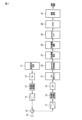
図1乃至図5は第1の実施形態に係るレーダ装置の構成、処理例を示しており、図1は送信系統及び受信系統の構成を示すブロック図、図2は送信系統で生成される送信信号を示すタイミング波形図、図3は受信信号のPRIによるCPIデータを示すタイミング図、図4はレンジセル毎のslow-time軸の受信信号の振幅変化を示す波形図、図5は低周波成分抑圧前と後のslow-time軸FFT後の信号を比較して示すレンジ-ドップラ図である。
(First embodiment)
A radar device according to a first embodiment will be described with reference to FIGS. 1 to 5.
1 to 5 show the configuration and processing example of a radar device according to the first embodiment, FIG. 1 is a block diagram showing the configuration of a transmission system and a reception system, and FIG. 2 is a transmission system generated by the transmission system. Figure 3 is a timing diagram showing CPI data based on PRI of the received signal. Figure 4 is a waveform diagram showing amplitude changes of the received signal on the slow-time axis for each range cell. Figure 5 is low frequency component suppression. It is a range-Doppler diagram showing a comparison of signals after slow-time axis FFT before and after.
まず、図1において、送信系統では、送信信号生成器11で変調パルス等の送信信号(図2)を生成し、DA変換器12によりアナログ信号に変換し、周波数変換器13で高周波(RF)信号に変換し、高出力増幅器14で電力増幅し、サーキュレータ15を介して、アンテナ16により送信する。受信系統では、目標等からの反射信号をアンテナ16で捕捉し、サーキュレータ15により送受分離して、低雑音増幅器17でノイズを低減して増幅した後、周波数変換器18でベースバンドに周波数変換し、AD変換器19でデジタル信号に変換する。
First, in FIG. 1, in the transmission system, a
以上の送受信信号は、N(N≧1)ヒットの送信パルスの受信信号(PRI信号、PRI:Pulse Repetition Interval)によるCPI(Coherent Pulse Interval)信号と呼ぶ。以下、目標検出処理を行う。まず、CPI信号入力部21は、AD変換器19から出力されるN(N≧1)ヒットの送信パルスの受信信号(PRI信号)を入力して受信信号からCPI信号を抽出する。slow-time信号抽出部22は、CPI信号からレンジセル毎のslow-time軸の信号(複素信号)を抽出する。近似曲線算出部23は、抽出されたslow-time軸の信号の近似曲線を算出する。近似曲線減算部24は、算出した近似曲線の信号を元の信号から減算することにより、低周波成分を抑圧する。slow-time FFT処理部25は、slow-time軸の信号をFFT(Fast Fourier Transform:高速フーリエ変換)処理して周波数領域の信号に変換する。CFAR処理部26は、周波数領域に変換されたslow-time軸の信号について、レンジセル毎にドップラ周波数軸でCFAR(Constant False Alarm Rate:一定誤警報率)処理を行って目標が存在するレンジ-ドップラセルを検出する。測距・測角処理部27は、検出されたレンジ-ドップラセルを測距・測角処理して目標情報として出力する。
The above transmission/reception signal is called a CPI (Coherent Pulse Interval) signal based on a reception signal (PRI signal, PRI: Pulse Repetition Interval) of N (N≧1) hit transmission pulses. Hereafter, target detection processing is performed. First, the CPI
上記構成において、第1の実施形態の目標検出処理について説明する。 In the above configuration, target detection processing of the first embodiment will be described.
上記CPI信号は、図3に示すように、レンジセル毎のfast-time軸とPRI間のslow-time軸の2次元データである。レンジセル毎のslow-time軸の受信信号は、図4に示すような振幅変化を持つ複素信号である。また、レンジセル毎のslow-time軸の受信信号には、目標信号やクラッタを含まれている。このうちのクラッタ、特に地上固定レーダにおけるグランドクラッタの場合は、ドップラ0付近の低周波数成分である。一方、目標信号は、固定目標で無い限り、速度によるドップラ成分を持つ。そこで、クラッタと目標信号を分離することを考える。 As shown in FIG. 3, the CPI signal is two-dimensional data of a fast-time axis for each range cell and a slow-time axis between PRIs. The slow-time axis received signal for each range cell is a complex signal with amplitude changes as shown in FIG. Furthermore, the slow-time axis received signal for each range cell includes a target signal and clutter. Among these, clutter, especially ground clutter in fixed ground radar, is a low frequency component near Doppler 0. On the other hand, unless the target is a fixed target, the target signal has a Doppler component due to velocity. Therefore, consider separating the clutter and the target signal.
まず、CPI信号(21)からレンジセル毎のslow-time軸の受信信号(複素信号)を抽出して(22)、図4に示すように、低次(m(m≧1)次)の近似曲線を算出する(23)。この近似曲線は、例えば(1)式に示す多項式近似式を用いて、最小2乗法等により係数を決めればよい。 First, the slow-time axis received signal (complex signal) for each range cell is extracted from the CPI signal (21) (22), and as shown in Figure 4, a low-order (m (m≧1) order) approximation is performed. Calculate the curve (23). For this approximate curve, the coefficients may be determined by the method of least squares or the like using, for example, the polynomial approximation formula shown in equation (1).

この際、次数mを大きくすると、クラッタ成分以上の目標信号まで近似するため、想定する目標信号まで抑圧しないように、低次の次数(例えば1~3程度)に設定する必要がある。ここで算出した近似式の信号を元の受信信号から減算することにより、低周波成分を抑圧する(24)。これを全レンジセル毎(fast-time軸セル)に繰り返し、slow-time軸でFFT処理して(25)、レンジセル毎にドップラ周波数軸でCFAR処理を行うことによりレンジ-ドップラセルの目標検出処理を行う(26)。目標を検出したレンジ-ドップラセルについては、測距・測角処理して、目標情報として出力する(27)。
At this time, if the order m is increased, it approximates a target signal that is higher than the clutter component, so it is necessary to set it to a low order (for example, about 1 to 3) so as not to suppress the expected target signal. By subtracting the signal of the approximate expression calculated here from the original received signal, low frequency components are suppressed (24). Repeat this for every range cell (fast-time axis cell), perform FFT processing on the slow-time axis (25), and perform CFAR processing on the Doppler frequency axis for each range cell to perform range-Doppler cell target detection processing. (26). The range-Doppler cell that detected the target undergoes distance measurement and angle measurement processing and is output as target information (27).
上記クラッタ成分を抑圧する様子を図5に示す。図5(a)は低周波数成分抑圧前のslow-time軸FFT処理後の信号を示し、図5(b)は低周波数成分抑圧後のslow-time軸FFT処理後の信号を示している。レンジ-ドプラ軸でクラッタを抑圧する前では、図5(a)に示すように、クラッタ成分の広がりにより、クラッタ近くの低速目標成分をクラッタ成分から分離することができず、クラッタ近くの低速目標は検出することができない。これに対して、図4に示した近似曲線の信号を減算してレンジ-ドプラ軸でクラッタを抑圧すると、図5(b)に示すように、クラッタ成分にシャープなヌルが形成される。これにより、クラッタ近くの低速目標成分をクラッタ成分から分離することが可能となり、クラッタのみを抑圧して低速目標成分を検出することができる。 FIG. 5 shows how the clutter components are suppressed. FIG. 5(a) shows a signal after slow-time axis FFT processing before low frequency component suppression, and FIG. 5(b) shows a signal after slow-time axis FFT processing after low frequency component suppression. Before suppressing clutter using the range-Doppler axis, as shown in Figure 5(a), the low-speed target component near the clutter cannot be separated from the clutter component due to the spread of the clutter component, and the low-speed target component near the clutter cannot be separated from the low-speed target component near the clutter. cannot be detected. On the other hand, when the signal of the approximate curve shown in FIG. 4 is subtracted to suppress clutter on the range-Doppler axis, a sharp null is formed in the clutter component as shown in FIG. 5(b). This makes it possible to separate the low-speed target component near the clutter from the clutter component, and it is possible to suppress only the clutter and detect the low-speed target component.
したがって、上記実施形態に係るレーダ装置は、本実施形態に係るレーダ装置は、fast-time軸のセル毎に、slow-time軸の複素信号から、m(m≧1)次の近似曲線を算出し、元の信号から減算することにより、低周波数の信号成分(クラッタ、近接反射波等)を抑圧して、目標検出処理(パルス圧縮、CFAR等)を行うようにしているので、低速目標信号を保持したままクラッタや近接反射信号を抑圧して、低速目標のみを検出することができる。 Therefore, the radar device according to the above embodiment calculates an m-th (m≧1) approximation curve from a complex signal on the slow-time axis for each cell on the fast-time axis. By subtracting it from the original signal, low frequency signal components (clutter, close reflected waves, etc.) are suppressed and target detection processing (pulse compression, CFAR, etc.) is performed. It is possible to detect only low-speed targets by suppressing clutter and proximity reflection signals while maintaining the
(第2の実施形態)
図6乃至図9を参照して、第2の実施形態に係るレーダ装置を説明する。
第1の実施形態では、パルスレーダのCPI信号に対して、fast-time軸のセル毎のslow-time軸の信号に対して近似曲線を減算する手法について述べた。パルスレーダの場合は、通常、送信時に受信することはないが、連続波レーダの場合は、送信しながら受信するので、送信~サーキュレータ~受信への回り込み成分が入力される。これを近接反射と呼ぶ。本実施形態では、FMCWレーダ等の連続波レーダの場合について、近接反射信号を抑圧する手法について述べる。
(Second embodiment)
A radar device according to a second embodiment will be described with reference to FIGS. 6 to 9.
In the first embodiment, a method was described in which an approximate curve is subtracted from a slow-time axis signal for each cell on a fast-time axis with respect to a CPI signal of a pulse radar. In the case of a pulse radar, normally the signal is not received while transmitting, but in the case of a continuous wave radar, the signal is received while transmitting, so a wrap-around component from the transmission to the circulator to the reception is input. This is called proximity reflection. In this embodiment, a method for suppressing a proximity reflected signal will be described in the case of a continuous wave radar such as an FMCW radar.
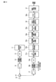
図6乃至図9は第2の実施形態に係るレーダ装置の構成、処理例を示しており、図6は送信系統及び受信系統の構成を示すブロック図、図7は送信系統で生成される連続スイープの送信変調信号と受信系統で得られるビート検出信号を示すタイミング波形図、図8はスイープ送信信号に対する受信信号のCPI信号を示すタイミング図、図9は受信系統で得られるslow-time軸スイープ番号毎のfast-time軸の受信信号の振幅変化を示す波形図である。なお、図6において、図1と同一部分には同一符号を付して示す。 6 to 9 show the configuration and processing examples of the radar device according to the second embodiment, FIG. 6 is a block diagram showing the configuration of the transmission system and the reception system, and FIG. 7 is a block diagram showing the configuration of the transmission system and the reception system. Timing waveform diagram showing the sweep transmit modulation signal and beat detection signal obtained in the receiving system. Figure 8 is a timing diagram showing the CPI signal of the received signal for the sweep transmit signal. Figure 9 is the slow-time axis sweep obtained in the receiving system. FIG. 7 is a waveform diagram showing the amplitude change of the fast-time axis received signal for each number. Note that in FIG. 6, the same parts as in FIG. 1 are denoted by the same reference numerals.
図6において、送信系統では、送信信号生成器11aにより、連続スイープの送信信号(送信変調信号)として図7(a)に示すアップスイープ1とダウンスイープ2の信号等を生成し、DA変換器12によりアナログ信号に変換し、周波数変換器13で高周波(RF)信号に変換し、高出力増幅器14で電力増幅し、サーキュレータ15を介して、アンテナ16により送信する。受信系統では、目標等からの反射信号をアンテナ16で捕捉し、サーキュレータ15により送受分離して、低雑音増幅器17でノイズを低減して増幅した後、周波数変換器18aでベースバンドに周波数変換する。ここで、周波数変換器18aにおいては、送信変調信号と同様に、スイープしたローカル周波数を用いて、図7(b)に示す受信信号との差分であるビート周波数を抽出する(非特許文献1参照)。受信系統では、周波数変換器18aから出力されるビート周波数の受信信号をAD変換器19でデジタル信号に変換する。
In FIG. 6, in the transmission system, the transmission signal generator 11a generates up-sweep 1 and down-
以上の送受信処理により、N(N≧1)スイープ(図7ではN=2の場合)の受信信号(図8)が得られる。以下、目標検出処理を行う。まず、CPI信号入力部31は、AD変換器19の出力からN(N≧1)スイープの送信信号によるビート周波数の受信信号からCPI信号を抽出する。fast-time信号抽出部32は、CPI信号からslow-time軸におけるスイープ番号毎のfast-time軸の信号(複素信号)を抽出する。近似曲線算出部33は、抽出されたfast-time軸の信号の近似曲線を算出する。近似曲線減算部34は、算出した近似曲線の信号を元の信号から減算することにより、低周波成分を抑圧する。fast-time FFT処理部35は、fast-time軸の信号をFFT処理して周波数領域の信号に変換する。CFAR処理部36は、周波数領域に変換されたfast-time軸の信号について、CFAR検出処理を行って目標が存在するfast-time軸とslow-time軸のセルを検出する。測距/測速・測角処理部37は、検出されたfast-time軸とslow-time軸のセルを測距/測速処理及び測角処理して目標情報として出力する。
Through the above transmission and reception processing, N (N≧1) sweep (in the case of N=2 in FIG. 7) received signals (FIG. 8) are obtained. Hereafter, target detection processing is performed. First, the CPI
上記構成において、第2の実施形態の目標検出処理について説明する。 In the above configuration, target detection processing according to the second embodiment will be described.
上記受信データにおいて、slow-time軸(スイープ)番号毎のfast-time軸の受信信号を図9に示す。この信号には、近接反射成分を含む。近接反射成分は、ドップラ0付近の低周波数成分である。一方、目標信号は、固定目標で無い限り、速度によるドップラ成分を持つ。ここで、近接反射と目標信号を分離することを考える。 In the above received data, the fast-time axis received signals for each slow-time axis (sweep) number are shown in FIG. This signal includes a close reflection component. The close reflection component is a low frequency component near 0 Doppler. On the other hand, unless the target is a fixed target, the target signal has a Doppler component due to velocity. Here, consider separating the proximity reflection and the target signal.
まず、スイープ毎のfast-time軸の受信信号(複素信号)を抽出して(32)、図9に示すように、低次(m(m≧1)次)の近似曲線を算出する(33)。この近似曲線は、例えば(2)式に示す多項式近似式を用いて、最小2乗法等により係数を決めればよい。 First, the fast-time axis received signal (complex signal) for each sweep is extracted (32), and a low-order (m (m≧1) order) approximate curve is calculated as shown in Figure 9 (33). ). For this approximate curve, the coefficients may be determined by the method of least squares or the like using, for example, the polynomial approximation formula shown in equation (2).

この際、次数mを大きくすると、近接周波数成分以上の目標信号まで近似するため、想定する目標信号まで抑圧しないように、低次の次数(例えば1~3程度)に設定する必要がある。ここで算出した近似式の信号を元の信号から減算することにより、低周波成分の近接反射信号を抑圧する(34)。これを全スイープ毎に繰り返す。この信号をfast-time軸でFFT処理して(35)、CFARによりfast-time軸とslow-time軸のセルの目標検出処理を行う(36)。検出したfast-time軸とslow-time軸のセルについては、FMCWの測距/測速処理と測角処理を行い(37)、目標情報として出力する。
At this time, if the order m is increased, the target signal of adjacent frequency components or higher will be approximated, so it is necessary to set it to a low order (for example, about 1 to 3) so as not to suppress the expected target signal. By subtracting the signal of the approximate expression calculated here from the original signal, the proximity reflection signal of the low frequency component is suppressed (34). Repeat this for every sweep. This signal is subjected to FFT processing on the fast-time axis (35), and target detection processing for cells on the fast-time axis and slow-time axis is performed using CFAR (36). The detected fast-time axis and slow-time axis cells are subjected to FMCW distance measurement/velocity measurement processing and angle measurement processing (37), and output as target information.
測距/測速・測角処理部37の距離と速度は、次式の演算による算出することができる(非特許文献1参照)。
The distance and speed of the distance measurement/velocity measurement/angle


上記の処理により、本実施形態に係るレーダ装置は、FMCWレーダ等の連続波レーダの場合について、fast-time軸の複素信号の低次の近似曲線を用いて近接反射信号を抑圧し、近接反射信号近くの低速目標成分を分離することが可能となり、近接反射信号のみを抑圧して低速目標成分を検出することができる。
Through the above processing, the radar device according to the present embodiment suppresses the proximity reflected signal using a low-order approximation curve of the complex signal on the fast-time axis in the case of continuous wave radar such as FMCW radar, and suppresses the proximity reflected signal. It becomes possible to separate the low-speed target component near the signal, and it is possible to detect the low-speed target component by suppressing only the nearby reflected signal.
(第3の実施形態)
図10乃至図12を参照して、第3の実施形態に係るレーダ装置を説明する。
第2の実施形態では、連続波レーダの場合の近接反射の抑圧手法について述べた。この受信信号は、周波数変換器の部分で直交検波をしている前提であり、AD変換後の信号は複素信号(実部+虚部の信号)の場合である。一方、周波数変換器を簡易化するためには、直交検波をしない場合もあり、その場合の受信信号は実数信号(実部)のみとなる。本実施形態では、実数信号のみで周波数変換を行う場合の方式を述べる。
(Third embodiment)
A radar device according to a third embodiment will be described with reference to FIGS. 10 to 12.
In the second embodiment, a method for suppressing proximity reflections in the case of continuous wave radar has been described. This received signal is assumed to undergo orthogonal detection in the frequency converter, and the signal after AD conversion is a complex signal (real part + imaginary part signal). On the other hand, in order to simplify the frequency converter, quadrature detection may not be performed, and in that case, the received signal is only a real number signal (real part). In this embodiment, a method will be described in which frequency conversion is performed using only real signals.
図10乃至図12は第3の実施形態に係るレーダ装置の構成及び処理例を示すもので、図10は送信系統及び受信系統の構成を示すブロック図、図11は受信系統で実数をfast-time軸FFTした信号から複素数の信号を生成する様子を示す波形図、図12は位相モノパルスによる測角処理を示す角度-振幅波形図及び角度-誤差電圧波形図である。 10 to 12 show the configuration and processing example of the radar device according to the third embodiment. FIG. 10 is a block diagram showing the configuration of the transmission system and the reception system, and FIG. FIG. 12 is a waveform diagram showing how a complex number signal is generated from a time-axis FFT signal. FIG. 12 is an angle-amplitude waveform diagram and an angle-error voltage waveform diagram showing angle measurement processing using a phase monopulse.
図10において、送信信号生成器11aにより、アップスイープ信号とダウンスイープ信号を生成した後、低雑音増幅器17までは、第2の実施形態と同様である。本実施形態では、第2の実施形態で用いた周波数変換器18の直交検波(ローカル信号を直交信号に分配して、それぞれで検波)を用いず、ローカル信号と直接検波する周波数変換器18bを用い、その出力をAD変換器19aでデジタル信号に変換することで実数信号による受信データを得る。この受信データは、第2の実施形態の複素信号を実数信号に置き換えれば、第2の実施形態と同様の演算で近似曲線を算出することができる。すなわち、CPI信号入力部31aは、AD変換器19aのN(N≧1)スイープの送信信号によるビート周波数の受信信号(実数)からCPI信号(実数)を抽出する。fast-time信号抽出部32aは、CPI信号(実数)からslow-time軸におけるスイープ番号毎のfast-time軸の信号(実数)を抽出する。近似曲線算出部33aは、抽出されたfast-time軸の信号(実数)の近似曲線を算出する。近似曲線減算部34aは、算出した近似曲線の信号(実数)を元の信号(実数)から減算することにより、低周波成分を抑圧する。fast-time FFT処理部35aは、fast-time軸の信号をFFT処理して周波数領域の信号(複素数)に変換する。ここで、周波数処理部38で負または正の周波数成分を0にする。CFAR処理部36aは、周波数成分が制限されたfast-time軸の信号(複素数)について、CFAR検出処理を行って目標が存在するfast-time軸のセルを検出する。測距/測速・測角処理部37は、検出されたfast-time軸のセルを測距/測速処理及び測角処理して目標情報として出力する。
In FIG. 10, after the up-sweep signal and the down-sweep signal are generated by the transmission signal generator 11a, the steps up to the low-
上記構成において、第3の実施形態の目標検出処理について説明する。 In the above configuration, target detection processing according to the third embodiment will be described.
まず、CPI信号入力部31で受信データからスイープ毎のfast-time軸の信号(実数信号)を抽出し(32a)、図11(a)に示すように、低次の近似曲線を算出する。この近似曲線は、例えば次式に示す多項式近似式を用いて、最小2乗法等により係数を決めればよい。
First, the CPI

この際、次数mを大きくすると、近接周波数成分以上の目標信号まで近似するため、想定する目標信号まで抑圧しないように、低次の次数(例えば1~3程度)に設定する必要がある。ここで算出した近似式を元の信号から減算することにより、低周波成分を抑圧する(34a)。これを全スイープ毎に繰り返す。
At this time, if the order m is increased, the target signal of adjacent frequency components or higher will be approximated, so it is necessary to set it to a low order (for example, about 1 to 3) so as not to suppress the expected target signal. By subtracting the approximate expression calculated here from the original signal, low frequency components are suppressed (34a). Repeat this for every sweep.
この信号は、実数信号であり、位相モノパルス処理(非特許文献2参照)等を行うためには、複素信号が必要である。このために、fast-time軸のFFT(複素数)を行う(35a)。なお、位相モノパルス処理では、アンテナ開口を分割(左右、上下等)して、分割信号の和信号Σと差信号(左右または上下)Δの信号が必要であるが、図10の系統では、わかりやすくするためにΣ系統のみを示している。Δ信号がある場合には、受信系統(低雑音増幅器17~周波数処理部38)がΔ信号の数分増えて、測距/測速・測角処理37の処理に入力されることになる。
This signal is a real signal, and a complex signal is required to perform phase monopulse processing (see Non-Patent Document 2). For this purpose, fast-time axis FFT (complex number) is performed (35a). In phase monopulse processing, the antenna aperture is divided (left and right, top and bottom, etc.) and the sum signal Σ and difference signal (left and right or top and bottom) Δ of the divided signals are required. For simplicity, only the Σ system is shown. If there is a Δ signal, the reception system (
実数をfast-time軸FFTした信号は、図11(b)に示すように、正と負の成分を持つため、これを複素信号にするために、まずは、図11(c)に示すように、負(正)の信号成分を0にする(38)。この信号から、fast-time軸の複素信号を得るには、図11(d)に示すように、fast-time軸で逆FFTするが、図10の系統では、fast-time軸の周波数のままCFAR処理するために、逆FFTの処理は含めていない。CFAR36aにより検出処理を行い検出したfast-time軸のセルについては、FMCWの測距/測速処理と測角処理を行い、目標情報として出力する(37)。距離と速度の演算式は、第2の実施形態と同様であるため、ここではその説明を省略する。測角処理については、図12(a)に示すΣビーム及びΔビームによる位相モノパルス処理を想定して、次式の誤差電圧を用いて演算を行う。
The signal obtained by fast-time axis FFT of real numbers has positive and negative components, as shown in Figure 11(b), so in order to convert it into a complex signal, first, as shown in Figure 11(c), , the negative (positive) signal components are set to 0 (38). To obtain a complex signal on the fast-time axis from this signal, an inverse FFT is performed on the fast-time axis as shown in Figure 11(d), but in the system shown in Figure 10, the frequency on the fast-time axis remains unchanged. In order to perform CFAR processing, inverse FFT processing is not included. The fast-time axis cells detected through detection processing by the

このように、簡易な周波数変換器を用いても、予め、アンテナ11のΣビームとΔビームの角度応答信号を測定して図12(b)の測角曲線を算出しておき、CFARにより検出したfast-time軸(fast-time軸FFT後の周波数軸)のセルについて、上記の誤差電圧εを観測すれば、測角値θを得ることができる。
In this way, even if a simple frequency converter is used, the angle response signals of the Σ beam and Δ beam of the
以上のように、本実施形態に係るレーダ装置は、fast-time軸の実数信号の低次の近似曲線を用いるようにしているので、低速目標信号を保持したままクラッタや近接反射信号を抑圧して、低速目標のみを検出することができる。 As described above, the radar device according to this embodiment uses a low-order approximation curve of the real signal on the fast-time axis, so it suppresses clutter and proximity reflection signals while maintaining the low-speed target signal. Therefore, only low-speed targets can be detected.
(第4の実施形態)
図13乃至図16を参照して、第4の実施形態に係るレーダ装置を説明する。
第1の実施形態では、クラッタ等の低周波数成分について、レンジ-ドップラ軸でヌルを形成(図5(b))することで、低速目標を検出する手法について述べた。レンジ-ドップラ軸にヌルを形成して、レンジセル毎にドップラ軸でCA(Cell-Averaging)-CFAR(非特許文献3参照)を実施すると、ヌルのエッジによる誤検出が発生する場合がある。本実施形態では、その対策について述べる。
(Fourth embodiment)
A radar device according to a fourth embodiment will be described with reference to FIGS. 13 to 16.
In the first embodiment, a method was described in which a low-speed target is detected by forming a null in the range-Doppler axis (FIG. 5(b)) for low frequency components such as clutter. If a null is formed on the range-Doppler axis and CA (Cell-Averaging)-CFAR (see Non-Patent Document 3) is performed on the Doppler axis for each range cell, false detection may occur due to the edge of the null. In this embodiment, countermeasures will be described.
図13乃至図16は第4の実施形態に係るレーダ装置の構成、処理例を示しており、図13は送信系統及び受信系統の構成を示すブロック図、図14は0ドップラを中心に設定されるGO(Greatest Of)-CFARの範囲とCA-CFARの範囲を示すレンジ-ドップラ図、図15はCA-CFARの手法とGO-CFARの手法を示すブロック図、図16はCA-CFARの場合とGO-CFARの場合のヌルのエッジ付近の処理の様子を比較して示す波形図である。 13 to 16 show the configuration and processing example of a radar device according to the fourth embodiment, FIG. 13 is a block diagram showing the configuration of a transmitting system and a receiving system, and FIG. 14 shows a configuration centered on 0 Doppler. Range-Doppler diagram showing the range of GO (Greatest Of)-CFAR and the range of CA-CFAR, Figure 15 is a block diagram showing the CA-CFAR method and GO-CFAR method, and Figure 16 is the case of CA-CFAR. FIG. 4 is a waveform chart showing a comparison of processing near the null edge in the case of GO-CFAR and GO-CFAR.
図13に示す送信系統及び受信系統の構成において、CFAR検出のための処理以外は、第1の実施形態と同様である。図13において、図1と同一部分には同一符号を付して、その説明を省略する。異なる点は、slow-time FFT処理部25の出力をCFAR種別切り替え処理部28に入力し、所定の条件に従ってGO-CFAR、CA-CFARのいずれかの種別を選定し、選定された種別のCFAR処理をCFAR処理部26aで実行するようにしたことにある。
The configurations of the transmission system and reception system shown in FIG. 13 are the same as those in the first embodiment except for the processing for CFAR detection. In FIG. 13, the same parts as in FIG. 1 are given the same reference numerals, and their explanations will be omitted. The difference is that the output of the slow-time
上記CFAR種別の条件を説明する。まず、ドップラの低周波数成分として、0ドップラを中心に所定の幅を設定する。所定の幅は、ドップラ分解能がCPI時間の逆数により決まるため、その±M倍(例えばM=10等)とする。図14に示すように、0ドップラを中心とする所定の幅内ではGO-CFARを選定し、それ以外ではCA-CFARとする。CA-CFARは、図15(a)に示すように、テストセルの両側のリファレンスセルの振幅平均の平均でテストセルを除算する手法である。一方、GO-CFARは、図15(b)に示すように、テストセルの両側のリファレンスセルの最大値によりテストセルを除算する手法である。クラッタ抑圧ヌルがある場合の動作を図16に示す。図16(a)に示すCA-CFARの場合は、テストセルとリファレンスセルをfast-time軸で順次スライディングさせながら、スレショルドを算出する。この場合、ヌルがあると、両側のリファレンスセルの平均値が低下することになり、スレショルドが低下し、ヌルのエッジ付近で誤検出が発生する場合がある。一方、図16(b)に示すGO-CFARの場合は、両側のリファレンスセルの最大値であるので、ヌルによる振幅低下が発生しにくい。このため、ヌルのエッジ付近でもスレショルドは高いままとなり、誤検出を抑圧することができる。 The conditions for the above CFAR types will be explained. First, a predetermined width is set around 0 Doppler as the low frequency component of Doppler. Since the Doppler resolution is determined by the reciprocal of the CPI time, the predetermined width is set to ±M times the reciprocal of the CPI time (for example, M=10, etc.). As shown in FIG. 14, GO-CFAR is selected within a predetermined width centered on 0 Doppler, and CA-CFAR is selected elsewhere. CA-CFAR is a method of dividing a test cell by the average amplitude of reference cells on both sides of the test cell, as shown in FIG. 15(a). On the other hand, GO-CFAR is a method of dividing the test cell by the maximum value of the reference cells on both sides of the test cell, as shown in FIG. 15(b). FIG. 16 shows the operation when there is a clutter suppression null. In the case of CA-CFAR shown in FIG. 16(a), the threshold is calculated while sequentially sliding the test cell and the reference cell on the fast-time axis. In this case, if there is a null, the average value of the reference cells on both sides will decrease, the threshold will decrease, and false detection may occur near the edge of the null. On the other hand, in the case of GO-CFAR shown in FIG. 16(b), since the value is the maximum value of the reference cells on both sides, amplitude reduction due to nulls is less likely to occur. Therefore, the threshold remains high even near the null edge, making it possible to suppress false detections.
ただし、GO-CFARは、ヌル付近の誤検出抑圧のためには有効であるが、スレショルドが上昇しやすいため、CA-CFARに比べて信号ロスを生じやすい。このため、ヌル近傍ではGO-CFARとし、その範囲以外ではCA-CFARを適用するとよい。 However, although GO-CFAR is effective for suppressing false detection near nulls, the threshold tends to rise, so it is more likely to cause signal loss than CA-CFAR. Therefore, it is recommended to use GO-CFAR near the null and CA-CFAR outside that range.
以上のように、本実施形態に係るレーダ装置は、クラッタや近接反射の抑圧によってドップラ周波数軸にヌルが形成され、ヌルの影響で誤検出が生じる場合でも、GO-CFARにすることで、誤検出を抑圧して、低速目標のみを検出することができる。 As described above, in the radar device according to the present embodiment, even if a null is formed on the Doppler frequency axis due to suppression of clutter or proximity reflections and false detection occurs due to the influence of the null, GO-CFAR can be used to prevent false detection. Detection can be suppressed to detect only low-speed targets.
(第5の実施形態)
図17及び図18を参照して、第4の実施形態に係るレーダ装置を説明する。
第4の実施形態では、クラッタヌルによる誤検出を抑圧するために、ドップラ周波数軸の1軸のCFARを切り替える手法について述べた。本実施形態では、他の手法について述べる。
(Fifth embodiment)
A radar device according to a fourth embodiment will be described with reference to FIGS. 17 and 18.
In the fourth embodiment, a method has been described in which the CFAR of one axis of the Doppler frequency axis is switched in order to suppress false detection due to clutter null. In this embodiment, another method will be described.
図17及び図16は第5の実施形態に係るレーダ装置の構成、処理例を示しており、図17は送信系統及び受信系統の構成を示すブロック図、図18はレンジ-ドップラ軸の2次元CFARを適用した場合の処理の様子を示すレンジ-ドップラ図である。 17 and 16 show the configuration and processing example of a radar device according to the fifth embodiment, FIG. 17 is a block diagram showing the configuration of the transmitting system and the receiving system, and FIG. 18 is a two-dimensional range-Doppler axis It is a range-Doppler diagram showing the state of processing when CFAR is applied.
図17に示す送信系統及び受信系統の構成において、CFAR検出のための処理以外は、第1の実施形態、第4の実施形態と同様である。図13において、図1及び図13と同一部分には同一符号を付して、その説明を省略する。異なる点は、レンジ-ドップラ軸の2次元CFAR処理部26bを用いてCFARの種別に対応した処理を実行するようにしたことにある。2次元CFARは、図18に示すように、テストセルの周囲に2次元のリファレンスセルを設けて、そのリファレンスセルの平均値(CA-CFAR)や最大値(GO-CFAR)を用いたCFARを適用することができる(非特許文献4参照)。CFARの切り替方式については、第4の実施形態と同様である。1次元CFARに比べて、リファレンスセル数が多く、クラッタ抑圧ヌルの影響を受けにくいため、レンジ-ドップラの全範囲をCA-CFARのみの選定にしてもよい。
The configurations of the transmission system and reception system shown in FIG. 17 are the same as those in the first embodiment and the fourth embodiment except for the processing for CFAR detection. In FIG. 13, the same parts as in FIGS. 1 and 13 are designated by the same reference numerals, and the explanation thereof will be omitted. The difference is that a range-Doppler axis two-dimensional
以上のように、本実施形態に係るレーダ装置は、クラッタや近接反射の抑圧によって、ドップラ周波数軸にヌルが形成され、ヌルの影響で誤検出が生じる場合でも、2次元CFARにすることで、誤検出を抑圧して、低速目標のみを検出することができる。 As described above, in the radar device according to the present embodiment, even if a null is formed on the Doppler frequency axis due to the suppression of clutter and proximity reflections and false detection occurs due to the influence of the null, by using two-dimensional CFAR, It is possible to suppress false detections and detect only low-speed targets.
上記の実施形態に係るレーダ装置によれば、Fast-time軸の複素信号から、N(N≧1)次の近似曲線を算出し、元の信号から減算することにより、低周波数の信号成分(クラッタ、近接反射等)を抑圧して、信号処理(パルス圧縮、CFAR等)するようにしているので、低速で移動する目標であっても、その位置をより高精度に検出することできる。 According to the radar device according to the above embodiment, the N (N≧1) order approximate curve is calculated from the complex signal on the fast-time axis, and the low-frequency signal component ( Clutter, proximity reflections, etc.) are suppressed and signal processing (pulse compression, CFAR, etc.) is performed, so even if the target is moving at low speed, its position can be detected with higher accuracy.
なお、本発明は上記実施形態をそのままに限定されるものではなく、実施段階ではその要旨を逸脱しない範囲で構成要素を変形して具体化できる。また、上記実施形態に開示されている複数の構成要素の適宜な組み合わせにより、種々の発明を形成できる。例えば、実施形態に示される全構成要素から幾つかの構成要素を削除してもよい。更に、異なる実施形態にわたる構成要素を適宜組み合わせてもよい。 It should be noted that the present invention is not limited to the above-described embodiments as they are, but can be embodied by modifying the constituent elements within the scope of the invention at the implementation stage. Moreover, various inventions can be formed by appropriately combining the plurality of components disclosed in the above embodiments. For example, some components may be deleted from all the components shown in the embodiments. Furthermore, components from different embodiments may be combined as appropriate.
11,11a…送信信号生成器、12…DA変換器、13…周波数変換器、14…高出力増幅器、15…サーキュレータ、16…アンテナ、17…低雑音増幅器、18,18a,18b…周波数変換器、19,19a…AD変換器、
21…CPI信号入力部、22…slow-time信号抽出部、23…近似曲線算出部、24…近似曲線減算部、25…slow-time FFT処理部、26,26a,26b…CFAR処理部、27…測距・測角処理部、28…CFAR種別切り替え処理部、
31…CPI信号入力部、32…fast-time信号抽出部、33…近似曲線算出部、34…近似曲線減算部、35…fast-time FFT処理部、36,36a…CFAR処理部、37…測距/測速・測角処理部、38…周波数処理部。
11, 11a... Transmission signal generator, 12... DA converter, 13... Frequency converter, 14... High output amplifier, 15... Circulator, 16... Antenna, 17... Low noise amplifier, 18, 18a, 18b... Frequency converter , 19, 19a...AD converter,
21... CPI signal input section, 22... slow-time signal extraction section, 23... approximate curve calculation section, 24... approximate curve subtraction section, 25... slow-time FFT processing section, 26, 26a, 26b... CFAR processing section, 27 ... Distance measurement/angle measurement processing section, 28... CFAR type switching processing section,
31... CPI signal input section, 32... fast-time signal extraction section, 33... approximate curve calculation section, 34... approximate curve subtraction section, 35... fast-time FFT processing section, 36, 36a... CFAR processing section, 37... measurement Distance/speed measurement/angle measurement processing section, 38...frequency processing section.
Claims (6)
前記CPI信号からレンジセル毎のslow-time軸の複素信号を抽出するslow-time信号抽出部と、
前記slow-time軸の複素信号のm(m≧1)次の近似曲線を算出する近似曲線算出部と、
前記近似曲線の複素信号を元のslow-time軸の複素信号から減算して低周波成分を抑圧する近似曲線減算部と、
前記低周波成分が抑圧されたslow-time軸の複素信号を周波数領域の信号に変換し、周波数領域に変換されたslow-time軸の複素信号について、レンジセル毎にドップラ周波数軸で0ドップラを中心に、所定の周波数セル幅内ではテストセルの両側のリファレンスセルの振幅最大値で前記テストセルを除算するGO(Greatest Of)-CFAR(Constant False Alarm Rate:一定誤警報率)を選定し、それ以外ではテストセルの両側のリファレンスセルの振幅平均で前記テストセルを除算するCA(Cell-Averaging)-CFARを選定して、それぞれのCFAR処理を実行することによって目標が存在するレンジ-ドップラセルを検出し、検出されたレンジ-ドップラセルを測距・測角処理して目標情報として出力する目標検出部と
を具備するレーダ装置。 The reception system receives the reflected signals of the transmission pulses that are transmitted in one scanning period in the range direction from the transmission system and has N (N≧1) hits. a CPI signal extraction unit that extracts a CPI (Coherent Pulse Interval) signal corresponding to the reception interval ;
a slow-time signal extraction unit that extracts a slow-time axis complex signal for each range cell from the CPI signal;
an approximate curve calculation unit that calculates an m (m≧1) order approximate curve of the complex signal on the slow-time axis;
an approximate curve subtraction unit that suppresses low frequency components by subtracting the complex signal of the approximate curve from the original slow-time axis complex signal;
The slow-time axis complex signal in which the low frequency components have been suppressed is converted into a frequency domain signal, and the converted slow-time axis complex signal is centered at 0 Doppler on the Doppler frequency axis for each range cell. Then, within a predetermined frequency cell width, select GO (Greatest Of)-CFAR (Constant False Alarm Rate), which divides the test cell by the maximum amplitude value of the reference cells on both sides of the test cell. Otherwise, select CA (Cell-Averaging)-CFAR that divides the test cell by the amplitude average of the reference cells on both sides of the test cell, and detect the range-Doppler cell where the target exists by executing each CFAR process. and a target detection unit that subjects the detected range-Doppler cell to distance measurement and angle measurement processing and outputs it as target information .
前記CPI信号からレンジセル毎のslow-time軸の複素信号を抽出するslow-time信号抽出部と、
前記slow-time軸の複素信号のm(m≧1)次の近似曲線を算出する近似曲線算出部と、
前記近似曲線の複素信号を元のslow-time軸の複素信号から減算して低周波成分を抑圧する近似曲線減算部と、
前記低周波成分が抑圧されたslow-time軸の複素信号を周波数領域の信号に変換し、周波数領域に変換されたslow-time軸の複素信号について、レンジセル毎にドップラ周波数軸で0ドップラを中心に、テストセルの周囲にレンジ-ドップラ周波数軸の2次元のリファレンスセルを設けて、そのリファレンスセルの振幅平均値または振幅最大値を用いて前記テストセルを除算する2次元CFAR(Constant False Alarm Rate:一定誤警報率)処理を行って目標が存在するレンジ-ドップラセルを検出し、検出されたレンジ-ドップラセルを測距・測角処理して目標情報として出力する目標検出部と
を具備するレーダ装置。 The reception system receives the reflected signals of the transmission pulses that are transmitted in one scanning period in the range direction from the transmission system and has N (N≧1) hits. a CPI signal extraction unit that extracts a CPI (Coherent Pulse Interval) signal corresponding to the reception interval;
a slow-time signal extraction unit that extracts a slow-time axis complex signal for each range cell from the CPI signal;
an approximate curve calculation unit that calculates an m (m≧1) order approximate curve of the complex signal on the slow-time axis;
an approximate curve subtraction unit that suppresses low frequency components by subtracting the complex signal of the approximate curve from the original slow-time axis complex signal;
The slow-time axis complex signal in which the low frequency components have been suppressed is converted into a frequency domain signal, and the converted slow-time axis complex signal is centered at 0 Doppler on the Doppler frequency axis for each range cell. CFAR (Constant False Alarm Rate) is a two-dimensional CFAR (Constant False Alarm Rate : constant false alarm rate) processing to detect the range-Doppler cell where the target is present, and process the detected range-Doppler cell for distance measurement and angle measurement and output it as target information.
A radar device equipped with .
前記CPI信号からslow-time軸におけるスイープ番号毎のfast-time軸の実数信号を抽出するfast-time信号抽出部と、
前記fast-time軸の実数信号のm(m≧1)次の近似曲線を算出する近似曲線算出部と、
前記近似曲線の実数信号を元のfast-time軸の実数信号から減算して低周波成分を抑圧する近似曲線減算部と、
前記低周波成分が抑圧されたfast-time軸の実数信号を複素数の周波数領域の信号に変換し、周波数領域に変換されたfast-time軸の複素数の信号について、正または負の周波数成分を0にして複素信号に変換し、CFAR(Constant False Alarm Rate:一定誤警報率)処理を行って目標が存在するfast-time軸のセルを検出し、検出されたfast-time軸のセルを測距/測速処理及び測角処理して目標情報として出力する目標検出部と
を具備するレーダ装置。 The reflected signal of the transmitted signal, which is transmitted from the transmitting system during one scanning period in the range direction and whose frequency modulation is a continuous N (N≧1) sweep , is received by the receiving system and is combined with the local frequency signal that matches the frequency modulation at the time of transmission. a CPI signal extracting unit that extracts a CPI (Coherent Pulse Interval) signal corresponding to each reception period of the real N sweep transmission signal from the mixed beat frequency reception signal;
a fast-time signal extraction unit that extracts a fast-time axis real number signal for each sweep number on the slow-time axis from the CPI signal;
an approximate curve calculation unit that calculates an m-th (m≧1) order approximate curve of the real signal on the fast-time axis;
an approximate curve subtraction unit that suppresses low frequency components by subtracting the real signal of the approximate curve from the original fast-time axis real signal;
The real signal on the fast-time axis in which the low frequency components have been suppressed is converted to a signal in the complex frequency domain, and the positive or negative frequency components of the complex signal on the fast-time axis converted to the frequency domain are set to 0. Convert it to a complex signal, perform CFAR (Constant False Alarm Rate) processing to detect the fast-time axis cell where the target exists, and measure the detected fast-time axis cell. / A radar device comprising a target detection unit that performs speed measurement processing and angle measurement processing and outputs the resultant target information .
前記CPI信号からレンジセル毎のslow-time軸の複素信号を抽出し、
前記slow-time軸の複素信号のm(m≧1)次の近似曲線を算出し、
前記近似曲線の複素信号を元のslow-time軸の複素信号から減算して低周波成分を抑圧し、
前記低周波成分が抑圧されたslow-time軸の複素信号を周波数領域の信号に変換し、周波数領域に変換されたslow-time軸の複素信号について、レンジセル毎にドップラ周波数軸で0ドップラを中心に、所定の周波数セル幅内ではテストセルの両側のリファレンスセルの振幅最大値で前記テストセルを除算するGO(Greatest Of)-CFAR(Constant False Alarm Rate:一定誤警報率)を選定し、それ以外ではテストセルの両側のリファレンスセルの振幅平均で前記テストセルを除算するCA(Cell-Averaging)-CFARを選定して、それぞれのCFAR処理を実行することによって目標が存在するレンジ-ドップラセルを検出し、検出されたレンジ-ドップラセルを測距・測角処理して目標情報として出力する
レーダ装置のレーダ信号処理方法。 The reception system receives the reflected signals of the transmission pulses that are transmitted in one scanning period in the range direction from the transmission system and has N (N≧1) hits. Extract the CPI (Coherent Pulse Interval) signal corresponding to the reception interval ,
Extract the slow-time axis complex signal for each range cell from the CPI signal,
Calculate the m (m≧1) order approximate curve of the complex signal on the slow-time axis,
subtracting the complex signal of the approximate curve from the original slow-time axis complex signal to suppress low frequency components;
The slow-time axis complex signal in which the low frequency components have been suppressed is converted into a frequency domain signal, and the converted slow-time axis complex signal is centered at 0 Doppler on the Doppler frequency axis for each range cell. Then, within a predetermined frequency cell width, select GO (Greatest Of)-CFAR (Constant False Alarm Rate), which divides the test cell by the maximum amplitude value of the reference cells on both sides of the test cell. Otherwise, select CA (Cell-Averaging)-CFAR that divides the test cell by the amplitude average of the reference cells on both sides of the test cell, and detect the range-Doppler cell where the target exists by executing each CFAR process. Then, the detected range-Doppler cell is subjected to ranging and angle measurement processing and output as target information.
Radar signal processing method for radar equipment.
前記CPI信号からレンジセル毎のslow-time軸の複素信号を抽出し、
前記slow-time軸の複素信号のm(m≧1)次の近似曲線を算出し、
前記近似曲線の複素信号を元のslow-time軸の複素信号から減算して低周波成分を抑圧し、
前記低周波成分が抑圧されたslow-time軸の複素信号を周波数領域の信号に変換し、周波数領域に変換されたslow-time軸の複素信号について、レンジセル毎にドップラ周波数軸で0ドップラを中心に、テストセルの周囲にレンジ-ドップラ周波数軸の2次元のリファレンスセルを設けて、そのリファレンスセルの振幅平均値または振幅最大値を用いて前記テストセルを除算する2次元CFAR(Constant False Alarm Rate:一定誤警報率)処理を行って目標が存在するレンジ-ドップラセルを検出し、検出されたレンジ-ドップラセルを測距・測角処理して目標情報として出力する
レーダ装置のレーダ信号処理方法。 The reception system receives the reflected signals of the transmission pulses that are transmitted in one scanning period in the range direction from the transmission system and has N (N≧1) hits. Extract the CPI (Coherent Pulse Interval) signal corresponding to the reception interval,
Extract the slow-time axis complex signal for each range cell from the CPI signal,
Calculate the m (m≧1) order approximate curve of the complex signal on the slow-time axis,
subtracting the complex signal of the approximate curve from the original slow-time axis complex signal to suppress low frequency components;
The slow-time axis complex signal in which the low frequency components have been suppressed is converted into a frequency domain signal, and the converted slow-time axis complex signal is centered at 0 Doppler on the Doppler frequency axis for each range cell. CFAR (Constant False Alarm Rate) is a two-dimensional CFAR (Constant False Alarm Rate (constant false alarm rate) processing to detect the range-Doppler cell where the target exists, process the detected range-Doppler cell for distance measurement and angle measurement, and output it as target information . Radar signal of the radar device Processing method.
前記CPI信号からslow-time軸におけるスイープ番号毎のfast-time軸の実数信号を抽出し、
前記fast-time軸の実数信号のm(m≧1)次の近似曲線を算出し、
前記近似曲線の実数信号を元のfast-time軸の実数信号から減算して低周波成分を抑圧し、
前記低周波成分が抑圧されたfast-time軸の実数信号を複素数の周波数領域の信号に変換し、周波数領域に変換されたfast-time軸の複素数の信号について、正または負の周波数成分を0にして複素信号に変換し、CFAR(Constant False Alarm Rate:一定誤警報率)処理を行って目標が存在するfast-time軸のセルを検出し、検出されたfast-time軸のセルを測距/測速処理及び測角処理して目標情報として出力する
レーダ装置のレーダ信号処理方法。 The reflected signal of the transmitted signal, which is transmitted from the transmitting system during one scanning period in the range direction and whose frequency modulation is a continuous N (N≧1) sweep , is received by the receiving system and is combined with the local frequency signal that matches the frequency modulation at the time of transmission. Extracting a CPI (Coherent Pulse Interval) signal corresponding to each reception period of the real N sweep transmission signal from the beat frequency reception signal by mixing ,
Extract the fast-time axis real number signal for each sweep number on the slow-time axis from the CPI signal,
Calculate the m (m ≧ 1) order approximate curve of the real signal on the fast-time axis,
subtracting the real number signal of the approximate curve from the original fast-time axis real number signal to suppress low frequency components;
The real signal on the fast-time axis in which the low frequency components have been suppressed is converted to a signal in the complex frequency domain, and the positive or negative frequency components of the complex signal on the fast-time axis converted to the frequency domain are set to 0. Convert it to a complex signal, perform CFAR (Constant False Alarm Rate) processing to detect the fast-time axis cell where the target exists, and measure the detected fast-time axis cell. / Perform speed measurement processing and angle measurement processing and output as target information
Radar signal processing method for radar equipment.
Priority Applications (1)
| Application Number | Priority Date | Filing Date | Title |
|---|---|---|---|
| JP2019230707A JP7399706B2 (en) | 2019-12-20 | 2019-12-20 | Radar device and its radar signal processing method |
Applications Claiming Priority (1)
| Application Number | Priority Date | Filing Date | Title |
|---|---|---|---|
| JP2019230707A JP7399706B2 (en) | 2019-12-20 | 2019-12-20 | Radar device and its radar signal processing method |
Publications (2)
| Publication Number | Publication Date |
|---|---|
| JP2021099244A JP2021099244A (en) | 2021-07-01 |
| JP7399706B2 true JP7399706B2 (en) | 2023-12-18 |
Family
ID=76541880
Family Applications (1)
| Application Number | Title | Priority Date | Filing Date |
|---|---|---|---|
| JP2019230707A Active JP7399706B2 (en) | 2019-12-20 | 2019-12-20 | Radar device and its radar signal processing method |
Country Status (1)
| Country | Link |
|---|---|
| JP (1) | JP7399706B2 (en) |
Families Citing this family (2)
| Publication number | Priority date | Publication date | Assignee | Title |
|---|---|---|---|---|
| JP7170948B2 (en) * | 2020-08-04 | 2022-11-14 | 三菱電機株式会社 | SIGNAL PROCESSING DEVICE, RADAR AND RADAR SIGNAL PROCESSING METHOD |
| KR102391935B1 (en) * | 2021-11-15 | 2022-04-28 | 한화시스템 주식회사 | Apparatus and method for estimating angle of the low velocity target in the radar |
Citations (4)
| Publication number | Priority date | Publication date | Assignee | Title |
|---|---|---|---|---|
| JP2013083467A (en) | 2011-10-06 | 2013-05-09 | Japan Aerospace Exploration Agency | Colored noise reduction method and apparatus for optical remote air flow measuring device |
| JP2014153088A (en) | 2013-02-05 | 2014-08-25 | Mitsubishi Electric Corp | Rader system and tracking processor |
| WO2018220701A1 (en) | 2017-05-30 | 2018-12-06 | 株式会社ソシオネクスト | Information processing device and detection device |
| JP2019100947A (en) | 2017-12-06 | 2019-06-24 | 株式会社東芝 | Radar device and radar signal processing method of the same |
Family Cites Families (3)
| Publication number | Priority date | Publication date | Assignee | Title |
|---|---|---|---|---|
| US5686919A (en) * | 1995-06-06 | 1997-11-11 | Jordan; James R. | Process for generating wind profiler data free of fixed ground clutter contamination |
| JP3296234B2 (en) * | 1997-03-04 | 2002-06-24 | 三菱電機株式会社 | Clutter suppression device and clutter suppression method |
| JPH11248829A (en) * | 1998-03-05 | 1999-09-17 | Mitsubishi Electric Corp | Radar apparatus |
-
2019
- 2019-12-20 JP JP2019230707A patent/JP7399706B2/en active Active
Patent Citations (4)
| Publication number | Priority date | Publication date | Assignee | Title |
|---|---|---|---|---|
| JP2013083467A (en) | 2011-10-06 | 2013-05-09 | Japan Aerospace Exploration Agency | Colored noise reduction method and apparatus for optical remote air flow measuring device |
| JP2014153088A (en) | 2013-02-05 | 2014-08-25 | Mitsubishi Electric Corp | Rader system and tracking processor |
| WO2018220701A1 (en) | 2017-05-30 | 2018-12-06 | 株式会社ソシオネクスト | Information processing device and detection device |
| JP2019100947A (en) | 2017-12-06 | 2019-06-24 | 株式会社東芝 | Radar device and radar signal processing method of the same |
Also Published As
| Publication number | Publication date |
|---|---|
| JP2021099244A (en) | 2021-07-01 |
Similar Documents
| Publication | Publication Date | Title |
|---|---|---|
| US11885903B2 (en) | FMCW radar with interference signal suppression using artificial neural network | |
| JP6726253B2 (en) | Radar detection with interference suppression | |
| US11693106B2 (en) | Multiple input multiple output (MIMO) frequency-modulated continuous-wave (FMCW) radar system | |
| US11693085B2 (en) | FMCW radar with interference signal suppression | |
| US10663559B2 (en) | Radar transceiver with phase noise cancellation | |
| Brooker | Mutual interference of millimeter-wave radar systems | |
| US10234541B2 (en) | FMCW radar device | |
| Rohling | Some radar topics: waveform design, range CFAR and target recognition | |
| KR101092567B1 (en) | Frequency modulated continuous wave rader and detecting method for distance and velocity of moving object using it | |
| JP2014182010A (en) | Radar apparatus | |
| CN110632587A (en) | Weak moving object monitoring method based on rapid FMCW radar | |
| CN106597427B (en) | A kind of ultrahigh speed object detection method | |
| JP2007322331A (en) | Radar device | |
| US9482744B1 (en) | Staggered pulse repetition frequency doppler processing | |
| JP7399706B2 (en) | Radar device and its radar signal processing method | |
| US20180372861A1 (en) | Systems for determining target direction and methods therefor | |
| JP2019105601A (en) | Rader system and radar signal processing method for the same | |
| JP2017161358A (en) | Radar device | |
| JP5460290B2 (en) | Radar equipment | |
| Casademont et al. | I-channel FMCW Doppler radar for long-range and high-velocity targets | |
| JP2009103510A (en) | Radar system | |
| Shimura et al. | An advanced wideband interference suppression technique using envelope detection and sorting for automotive FMCW radar | |
| Ivanov et al. | CFAR multi-target detection based on non-central Chi-square distribution for FMCW | |
| JP2013113723A (en) | Radar system | |
| JP2023001662A (en) | Radar system, and radar signal processing method |
Legal Events
| Date | Code | Title | Description |
|---|---|---|---|
| A621 | Written request for application examination |
Free format text: JAPANESE INTERMEDIATE CODE: A621 Effective date: 20221021 |
|
| A977 | Report on retrieval |
Free format text: JAPANESE INTERMEDIATE CODE: A971007 Effective date: 20230731 |
|
| A131 | Notification of reasons for refusal |
Free format text: JAPANESE INTERMEDIATE CODE: A131 Effective date: 20230822 |
|
| A521 | Request for written amendment filed |
Free format text: JAPANESE INTERMEDIATE CODE: A523 Effective date: 20231023 |
|
| TRDD | Decision of grant or rejection written | ||
| A01 | Written decision to grant a patent or to grant a registration (utility model) |
Free format text: JAPANESE INTERMEDIATE CODE: A01 Effective date: 20231107 |
|
| A61 | First payment of annual fees (during grant procedure) |
Free format text: JAPANESE INTERMEDIATE CODE: A61 Effective date: 20231206 |
|
| R150 | Certificate of patent or registration of utility model |
Ref document number: 7399706 Country of ref document: JP Free format text: JAPANESE INTERMEDIATE CODE: R150 |