JP7399619B2 - Safe anode for electrochemical cells - Google Patents
Safe anode for electrochemical cells Download PDFInfo
- Publication number
- JP7399619B2 JP7399619B2 JP2018556386A JP2018556386A JP7399619B2 JP 7399619 B2 JP7399619 B2 JP 7399619B2 JP 2018556386 A JP2018556386 A JP 2018556386A JP 2018556386 A JP2018556386 A JP 2018556386A JP 7399619 B2 JP7399619 B2 JP 7399619B2
- Authority
- JP
- Japan
- Prior art keywords
- anode
- titanium
- current limiter
- vertical
- electrochemical cell
- Prior art date
- Legal status (The legal status is an assumption and is not a legal conclusion. Google has not performed a legal analysis and makes no representation as to the accuracy of the status listed.)
- Active
Links
- 239000010936 titanium Substances 0.000 claims description 122
- 229910052719 titanium Inorganic materials 0.000 claims description 122
- RTAQQCXQSZGOHL-UHFFFAOYSA-N Titanium Chemical compound [Ti] RTAQQCXQSZGOHL-UHFFFAOYSA-N 0.000 claims description 121
- 238000009826 distribution Methods 0.000 claims description 77
- RYGMFSIKBFXOCR-UHFFFAOYSA-N Copper Chemical compound [Cu] RYGMFSIKBFXOCR-UHFFFAOYSA-N 0.000 claims description 35
- 229910052802 copper Inorganic materials 0.000 claims description 35
- 239000010949 copper Substances 0.000 claims description 35
- 229910052751 metal Inorganic materials 0.000 claims description 20
- 239000002184 metal Substances 0.000 claims description 20
- 238000000429 assembly Methods 0.000 claims description 14
- 230000000712 assembly Effects 0.000 claims description 14
- 238000005363 electrowinning Methods 0.000 claims description 13
- 239000011810 insulating material Substances 0.000 claims description 13
- 239000004020 conductor Substances 0.000 claims description 10
- 239000000463 material Substances 0.000 claims description 10
- 150000002739 metals Chemical class 0.000 claims description 10
- 239000000956 alloy Substances 0.000 claims description 9
- 229910045601 alloy Inorganic materials 0.000 claims description 9
- 239000003822 epoxy resin Substances 0.000 claims description 8
- 229920000647 polyepoxide Polymers 0.000 claims description 8
- 239000011133 lead Substances 0.000 claims description 5
- 229910052782 aluminium Inorganic materials 0.000 claims description 4
- XAGFODPZIPBFFR-UHFFFAOYSA-N aluminium Chemical compound [Al] XAGFODPZIPBFFR-UHFFFAOYSA-N 0.000 claims description 4
- 239000011248 coating agent Substances 0.000 claims description 4
- 238000000576 coating method Methods 0.000 claims description 4
- 239000012212 insulator Substances 0.000 claims description 3
- 239000004411 aluminium Substances 0.000 claims description 2
- CWYNVVGOOAEACU-UHFFFAOYSA-N Fe2+ Chemical compound [Fe+2] CWYNVVGOOAEACU-UHFFFAOYSA-N 0.000 claims 1
- QAOWNCQODCNURD-UHFFFAOYSA-N Sulfuric acid Chemical compound OS(O)(=O)=O QAOWNCQODCNURD-UHFFFAOYSA-N 0.000 description 8
- 239000002253 acid Substances 0.000 description 8
- 230000000694 effects Effects 0.000 description 8
- 239000003792 electrolyte Substances 0.000 description 7
- 238000004519 manufacturing process Methods 0.000 description 7
- 238000000034 method Methods 0.000 description 7
- 230000008569 process Effects 0.000 description 7
- AZDRQVAHHNSJOQ-UHFFFAOYSA-N alumane Chemical group [AlH3] AZDRQVAHHNSJOQ-UHFFFAOYSA-N 0.000 description 6
- 239000003595 mist Substances 0.000 description 6
- 239000004593 Epoxy Substances 0.000 description 5
- 238000009434 installation Methods 0.000 description 5
- 238000003466 welding Methods 0.000 description 5
- QVGXLLKOCUKJST-UHFFFAOYSA-N atomic oxygen Chemical compound [O] QVGXLLKOCUKJST-UHFFFAOYSA-N 0.000 description 4
- 230000006378 damage Effects 0.000 description 4
- 238000005868 electrolysis reaction Methods 0.000 description 4
- 239000001301 oxygen Substances 0.000 description 4
- 229910052760 oxygen Inorganic materials 0.000 description 4
- 230000002093 peripheral effect Effects 0.000 description 4
- 230000008901 benefit Effects 0.000 description 3
- 238000000151 deposition Methods 0.000 description 3
- 230000008021 deposition Effects 0.000 description 3
- 239000004033 plastic Substances 0.000 description 3
- 229920000642 polymer Polymers 0.000 description 3
- PXHVJJICTQNCMI-UHFFFAOYSA-N Nickel Chemical compound [Ni] PXHVJJICTQNCMI-UHFFFAOYSA-N 0.000 description 2
- 230000002378 acidificating effect Effects 0.000 description 2
- 230000005611 electricity Effects 0.000 description 2
- 238000003912 environmental pollution Methods 0.000 description 2
- 238000009413 insulation Methods 0.000 description 2
- 230000009467 reduction Effects 0.000 description 2
- 239000000126 substance Substances 0.000 description 2
- ZAMOUSCENKQFHK-UHFFFAOYSA-N Chlorine atom Chemical compound [Cl] ZAMOUSCENKQFHK-UHFFFAOYSA-N 0.000 description 1
- 230000002411 adverse Effects 0.000 description 1
- 239000010405 anode material Substances 0.000 description 1
- 230000004888 barrier function Effects 0.000 description 1
- 230000005540 biological transmission Effects 0.000 description 1
- 230000008859 change Effects 0.000 description 1
- 239000000460 chlorine Substances 0.000 description 1
- 229910052801 chlorine Inorganic materials 0.000 description 1
- 230000002860 competitive effect Effects 0.000 description 1
- 229910000365 copper sulfate Inorganic materials 0.000 description 1
- ARUVKPQLZAKDPS-UHFFFAOYSA-L copper(II) sulfate Chemical compound [Cu+2].[O-][S+2]([O-])([O-])[O-] ARUVKPQLZAKDPS-UHFFFAOYSA-L 0.000 description 1
- 230000007797 corrosion Effects 0.000 description 1
- 238000005260 corrosion Methods 0.000 description 1
- 238000005520 cutting process Methods 0.000 description 1
- 230000007423 decrease Effects 0.000 description 1
- 230000003247 decreasing effect Effects 0.000 description 1
- 230000006866 deterioration Effects 0.000 description 1
- 239000006185 dispersion Substances 0.000 description 1
- 238000003487 electrochemical reaction Methods 0.000 description 1
- 239000008151 electrolyte solution Substances 0.000 description 1
- 230000007613 environmental effect Effects 0.000 description 1
- -1 ferrous metals Chemical class 0.000 description 1
- 239000007789 gas Substances 0.000 description 1
- 230000036541 health Effects 0.000 description 1
- 238000010348 incorporation Methods 0.000 description 1
- 239000004615 ingredient Substances 0.000 description 1
- 230000010354 integration Effects 0.000 description 1
- 150000002500 ions Chemical class 0.000 description 1
- 230000007246 mechanism Effects 0.000 description 1
- 229910052759 nickel Inorganic materials 0.000 description 1
- 230000003647 oxidation Effects 0.000 description 1
- 238000007254 oxidation reaction Methods 0.000 description 1
- 150000002926 oxygen Chemical class 0.000 description 1
- 230000036961 partial effect Effects 0.000 description 1
- 238000000926 separation method Methods 0.000 description 1
- 239000007787 solid Substances 0.000 description 1
- 239000000243 solution Substances 0.000 description 1
- 230000004083 survival effect Effects 0.000 description 1
- 239000000725 suspension Substances 0.000 description 1
Images


Classifications
-
- C—CHEMISTRY; METALLURGY
- C25—ELECTROLYTIC OR ELECTROPHORETIC PROCESSES; APPARATUS THEREFOR
- C25C—PROCESSES FOR THE ELECTROLYTIC PRODUCTION, RECOVERY OR REFINING OF METALS; APPARATUS THEREFOR
- C25C7/00—Constructional parts, or assemblies thereof, of cells; Servicing or operating of cells
-
- C—CHEMISTRY; METALLURGY
- C25—ELECTROLYTIC OR ELECTROPHORETIC PROCESSES; APPARATUS THEREFOR
- C25C—PROCESSES FOR THE ELECTROLYTIC PRODUCTION, RECOVERY OR REFINING OF METALS; APPARATUS THEREFOR
- C25C7/00—Constructional parts, or assemblies thereof, of cells; Servicing or operating of cells
- C25C7/02—Electrodes; Connections thereof
-
- C—CHEMISTRY; METALLURGY
- C25—ELECTROLYTIC OR ELECTROPHORETIC PROCESSES; APPARATUS THEREFOR
- C25B—ELECTROLYTIC OR ELECTROPHORETIC PROCESSES FOR THE PRODUCTION OF COMPOUNDS OR NON-METALS; APPARATUS THEREFOR
- C25B11/00—Electrodes; Manufacture thereof not otherwise provided for
- C25B11/04—Electrodes; Manufacture thereof not otherwise provided for characterised by the material
- C25B11/051—Electrodes formed of electrocatalysts on a substrate or carrier
- C25B11/073—Electrodes formed of electrocatalysts on a substrate or carrier characterised by the electrocatalyst material
-
- C—CHEMISTRY; METALLURGY
- C25—ELECTROLYTIC OR ELECTROPHORETIC PROCESSES; APPARATUS THEREFOR
- C25C—PROCESSES FOR THE ELECTROLYTIC PRODUCTION, RECOVERY OR REFINING OF METALS; APPARATUS THEREFOR
- C25C1/00—Electrolytic production, recovery or refining of metals by electrolysis of solutions
- C25C1/12—Electrolytic production, recovery or refining of metals by electrolysis of solutions of copper
-
- C—CHEMISTRY; METALLURGY
- C25—ELECTROLYTIC OR ELECTROPHORETIC PROCESSES; APPARATUS THEREFOR
- C25D—PROCESSES FOR THE ELECTROLYTIC OR ELECTROPHORETIC PRODUCTION OF COATINGS; ELECTROFORMING; APPARATUS THEREFOR
- C25D17/00—Constructional parts, or assemblies thereof, of cells for electrolytic coating
- C25D17/10—Electrodes, e.g. composition, counter electrode
-
- H—ELECTRICITY
- H01—ELECTRIC ELEMENTS
- H01H—ELECTRIC SWITCHES; RELAYS; SELECTORS; EMERGENCY PROTECTIVE DEVICES
- H01H85/00—Protective devices in which the current flows through a part of fusible material and this current is interrupted by displacement of the fusible material when this current becomes excessive
-
- C—CHEMISTRY; METALLURGY
- C25—ELECTROLYTIC OR ELECTROPHORETIC PROCESSES; APPARATUS THEREFOR
- C25B—ELECTROLYTIC OR ELECTROPHORETIC PROCESSES FOR THE PRODUCTION OF COMPOUNDS OR NON-METALS; APPARATUS THEREFOR
- C25B11/00—Electrodes; Manufacture thereof not otherwise provided for
- C25B11/02—Electrodes; Manufacture thereof not otherwise provided for characterised by shape or form
-
- C—CHEMISTRY; METALLURGY
- C25—ELECTROLYTIC OR ELECTROPHORETIC PROCESSES; APPARATUS THEREFOR
- C25B—ELECTROLYTIC OR ELECTROPHORETIC PROCESSES FOR THE PRODUCTION OF COMPOUNDS OR NON-METALS; APPARATUS THEREFOR
- C25B15/00—Operating or servicing cells
- C25B15/06—Detection or inhibition of short circuits in the cell
-
- Y—GENERAL TAGGING OF NEW TECHNOLOGICAL DEVELOPMENTS; GENERAL TAGGING OF CROSS-SECTIONAL TECHNOLOGIES SPANNING OVER SEVERAL SECTIONS OF THE IPC; TECHNICAL SUBJECTS COVERED BY FORMER USPC CROSS-REFERENCE ART COLLECTIONS [XRACs] AND DIGESTS
- Y02—TECHNOLOGIES OR APPLICATIONS FOR MITIGATION OR ADAPTATION AGAINST CLIMATE CHANGE
- Y02E—REDUCTION OF GREENHOUSE GAS [GHG] EMISSIONS, RELATED TO ENERGY GENERATION, TRANSMISSION OR DISTRIBUTION
- Y02E60/00—Enabling technologies; Technologies with a potential or indirect contribution to GHG emissions mitigation
- Y02E60/10—Energy storage using batteries
Landscapes
- Chemical & Material Sciences (AREA)
- Engineering & Computer Science (AREA)
- Chemical Kinetics & Catalysis (AREA)
- Electrochemistry (AREA)
- Materials Engineering (AREA)
- Metallurgy (AREA)
- Organic Chemistry (AREA)
- Electrodes For Compound Or Non-Metal Manufacture (AREA)
- Electrolytic Production Of Metals (AREA)
- Battery Electrode And Active Subsutance (AREA)
- Cell Electrode Carriers And Collectors (AREA)
- Electrolytic Production Of Non-Metals, Compounds, Apparatuses Therefor (AREA)
Description
本明細書は電気化学セルのための安全なアノードについて述べており、銅などの金属の電解採取のためのセルに適用可能である。 This specification describes safe anodes for electrochemical cells and is applicable to cells for electrowinning of metals such as copper.
最初に、容器、タンク、または電気化学セルは、他の成分の中でも、堆積されることになる金属から作られた電解質溶液によって満たされ、その中に交互の位置においてアノード/カソードペアが沈められ、これは電流が供給されたとき、カソード上に金属を堆積すると言うことができる。 First, a vessel, tank, or electrochemical cell is filled with an electrolyte solution made from the metal to be deposited, among other ingredients, into which anode/cathode pairs are submerged in alternating positions. , which can be said to deposit metal on the cathode when current is supplied.
これは垂直アノードが金属の電解採取のためにセル内で用いられるとき、垂直アノードは水平電流供給導体バーと、電流供給バーに接続された垂直配電バーとに基づいた吊り下げ構造から構成され、その配電バーは銅またはアルミニウムコア、およびチタン外層または外皮によって定義されることを意味する。 This means that when a vertical anode is used in a cell for the electrowinning of metals, the vertical anode consists of a hanging structure based on a horizontal current supply conductor bar and a vertical distribution bar connected to the current supply bar; That means the distribution bar is defined by a copper or aluminum core, and a titanium outer layer or skin.
従ってコーティングされたまたは無コーティングのチタンアノードプレートは配電バーに電気的に接続され、陽極電気分解はアノードプレートの表面上で行われる。 The coated or uncoated titanium anode plate is thus electrically connected to the distribution bar and anodic electrolysis takes place on the surface of the anode plate.
従来型アノードは、水平電流供給バー当たりの垂直バーの数の点で複数の組み合わせを呈する。 Conventional anodes exhibit multiple combinations in the number of vertical bars per horizontal current supply bar.
示されたように、金属の電解採取のための過程において用いられる従来型垂直バーは、銅またはアルミニウムコア、およびチタン外層または外皮を有するバイメタルのバーである。銅またはアルミニウムは、大電流の効果的な伝達のために必要な低い電気抵抗率を呈し、チタンは同時に、コーティングされたまたは無コーティングのチタンアノードプレートのこれらの垂直バーへの接続を可能にしながら、電解質の化学的腐食に対して銅またはアルミニウムを保護する。 As indicated, conventional vertical bars used in processes for the electrowinning of metals are bimetallic bars with a copper or aluminum core and a titanium outer layer or skin. Copper or aluminum exhibits the low electrical resistivity necessary for effective transmission of large currents, while titanium simultaneously allows the connection of coated or uncoated titanium anode plates to these vertical bars. , protect copper or aluminum against electrolyte chemical corrosion.
このようにして、最適な出力および最大能力を得るために、金属の電解採取のための過程において用いられるアノード、および具体的にはアノード表面は、カソードの近くで動作し、短いアノード-カソード距離に対して大きな表面積、例えば5cmの離隔距離で100×100センチメートルの表面を有する。これは必然的に、カソード表面上のいずれかの点において平坦さの変形または変化があった場合、アノードとカソードとの間の電気的接触、または言い換えれば短絡のリスクをもたらす。 In this way, in order to obtain optimal output and maximum capacity, the anode, and specifically the anode surface, used in the process for electrowinning of metals is operated close to the cathode, with a short anode-cathode distance. 100 x 100 cm with a separation distance of 5 cm. This necessarily results in a risk of electrical contact between the anode and cathode, or in other words a short circuit, if there is a deformation or change in flatness at any point on the cathode surface.
陰極表面はもともと不安定であり、なぜならそれらの厚さは生産過程自体の間に急速に変化するからであり、およびまたその表面上の単一の点でのカソードの厚さにおける増加はアノード-カソード距離を減少させ、これは電気抵抗を減少させ、オームの法則を適用すると問題の点におけるイオン電流を増加させるからである。 Cathode surfaces are inherently unstable because their thickness changes rapidly during the production process itself, and also the increase in cathode thickness at a single point on its surface is anode- Decreasing the cathode distance, since this reduces the electrical resistance and, applying Ohm's law, increases the ionic current at the point in question.
電流またはイオン堆積を増加させることはそれらの点に堆積された金属の厚さを増加させ、それによりこれらの事象は明らかに正帰還系を呈し、これは知られているように本質的に不安点なプロセスであり、これらの場合においてアノード-カソード接触または短絡を生じることになる。 Increasing the current or ion deposition increases the thickness of metal deposited at those points, so these events clearly exhibit a positive feedback system, which is known to be inherently unstable. This is a point process and will result in anode-cathode contacts or shorts in these cases.
さらにアラインメント誤差または既存の機械的変形も、直接のアノード-カソード接触、または短絡を引き起こすことになる。 Additionally, alignment errors or pre-existing mechanical deformations will also cause direct anode-cathode contact or short circuits.
アノードとカソードとの間に直接の電気的接触が確立されると、電解質とアノードとの間の潜在的な電気化学的バリアは消失し、電解質の比較的高い抵抗も除去されることになる。これらの状況において電流は許容できない値まで急上昇し、コーティングされたまたは無コーティングのチタンアノードプレートを損傷または破壊し同時に、著しい生産損失を引き起こす。 Once direct electrical contact is established between the anode and cathode, the potential electrochemical barrier between the electrolyte and the anode will disappear and the relatively high resistance of the electrolyte will also be removed. In these situations, the current spikes to unacceptable values, damaging or destroying the coated or uncoated titanium anode plate, while causing significant production losses.
また金属および具体的には銅の電解採取のためのセル内のアノードの作業過程において、「酸ミスト」として知られている現象である、硫酸を有する酸素気泡が生成される。この「酸ミスト」は重大な環境汚染問題を生じ、工場作業者の健康に直接影響を及ぼす可能性があり、セル室内のマスクの使用が必要となり、工場が位置する領域内の環境の悪化を生じ得る。 Also, during the operation of the anode in cells for the electrowinning of metals and specifically copper, oxygen bubbles with sulfuric acid are produced, a phenomenon known as "acid mist". This "acid mist" creates a serious environmental pollution problem and can directly affect the health of factory workers, necessitating the use of masks inside cell rooms and reducing the deterioration of the environment within the area where the factory is located. can occur.
例えば銅電解採取の場合において、電解質は主として硫酸および硫酸銅の溶液から作られる。その正常な電気分解過程において、アノードは硫酸を保持した汚染された酸素気泡を生成し、これらの気泡の大部分は電解質から出て、周囲雰囲気の一部となり、酸ミストとして知られているものを生成する。 For example, in the case of copper electrowinning, the electrolyte is made primarily from a solution of sulfuric acid and copper sulfate. During its normal electrolysis process, the anode generates contaminated oxygen bubbles that retain sulfuric acid, and most of these bubbles leave the electrolyte and become part of the surrounding atmosphere, creating what is known as acid mist. generate.
さらに、電流制限器は特定の値を超えるすべての電流に反応し、その電流を打ち消す装置であり、この値は特定の装置またはモデルの特性である。 Furthermore, a current limiter is a device that reacts to and cancels out any current that exceeds a certain value, and this value is a characteristic of a particular device or model.
よく知られている例は、我々の家庭内のヒューズであり、ネットワーク内で短絡または線材の直接接触があったとき、ヒューズは飛ばされて切断し、我々は暗闇に置かれる。それにより我々は、再び照明をもたらすためにヒューズをリセットまたは交換しなければならない。我々はこの例を用いてリセットすることの概念を説明しさらに、物理的短絡がもはや存在しなくなった場合、外部の介入なしに、ある期間の後に自動的に照明をもとにもどす可能性に関してより詳しく立ち入る。この場合ヒューズは自動リセットヒューズである。 A well-known example is the fuses in our homes, when there is a short circuit or direct contact of wires in the network, the fuse blows and disconnects, leaving us in the dark. Thereby we have to reset or replace the fuse to bring the lighting again. We use this example to explain the concept of resetting and furthermore regarding the possibility of automatically switching the lighting back on after a period of time, without external intervention, if a physical short circuit no longer exists. Let's go into more detail. In this case the fuse is a self-resetting fuse.
短絡に対して保護するための2つの方法があり、一方は電流を打ち消すまたはゼロに強制することであり、他方は電流を許容できるより低い値まで変調することである。両方の場合が電流制限器と見なされるが、我々は前者をデジタルオン-オフ制限器、後者をアナログ制限器と呼ぶことにする。 There are two ways to protect against short circuits, one is to cancel or force the current to zero, and the other is to modulate the current to an acceptable lower value. Although both cases are considered current limiters, we will refer to the former as a digital on-off limiter and the latter as an analog limiter.
また我々は、金属の電解採取のためのアノード構造を述べた、特許文献WO 2015/079072を引用することができ、これは水平支持バーと、プラスチックまたはエポキシでコーティングされたおよび垂直バーとを備え、垂直バーには25から225cm2の面積を有するサブメッシュと呼ばれるアノードプレートが取り付けられ、アノードプレートにはそれぞれの配線および/またはプリント回路によって電気が供給され、それらは一連の絶縁構造によって保護され、プラスチックまたはエポキシでコーティングされたバーの内側に設置される。 We may also cite patent document WO 2015/079072, which describes an anode structure for the electrowinning of metals, comprising a horizontal support bar and a vertical bar coated with plastic or epoxy. , the vertical bars are fitted with anode plates, called sub-mesh, with an area of 25 to 225 cm2 , the anode plates are supplied with electricity by respective wires and/or printed circuits, which are protected by a series of insulating structures. , installed inside a bar coated with plastic or epoxy.
本明細書の表題に表されるように以下の本発明は、電気化学セルにおいて、および具体的には金属の電解採取において用いられる、垂直アノードのタイプの電気化学セルのための安全なアノードに関し、アノードは吊り下げ構造からなり、水平電流供給導体バーと、電流供給バーに接続された垂直配電バーであって、銅またはアルミニウムコア、およびチタン外層または外皮によって定義される配電バーとに基づく。 The present invention below as expressed in the title of the present specification relates to a safe anode for electrochemical cells of the type of vertical anode used in electrochemical cells and in particular in the electrowinning of metals. , the anode consists of a suspended structure and is based on a horizontal current supply conductor bar and a vertical distribution bar connected to the current supply bar, defined by a copper or aluminum core and a titanium outer layer or skin.
この従来型実施形態に基づいて本発明の第1の目的は、コーティングされたまたは無コーティングのチタンアノードプレートを破壊または損傷し得る短絡を防止するために、垂直配電バーと、コーティングされたまたは無コーティングのチタンアノードプレートとの間の電気的接続が、電流制限器アセンブリを備えたそれぞれのアダプタ要素によってもたらされることである。 Based on this conventional embodiment, the first object of the present invention is to connect the vertical distribution bar with the coated or uncoated titanium anode plate in order to prevent short circuits that could destroy or damage the coated or uncoated titanium anode plate. Electrical connection between the coating and the titanium anode plate is provided by respective adapter elements with current limiter assemblies.
本発明の第2の目的は、硫酸を有する酸素気泡の放散を、それらをアノードの中央部分を通して導いて低減することであり、その理由のためにアノードプレートは垂直配電バーによって定義される垂直平面に対してある角度で配置され、それらを運ぶ煙突効果を生成し、捕集器による捕集を容易にし、有害な「酸ミスト」およびその重大な環境への影響を回避する。 A second objective of the invention is to reduce the dissipation of oxygen bubbles with sulfuric acid by directing them through the central part of the anode, for which reason the anode plate has a vertical plane defined by vertical distribution bars. placed at an angle to the air, creating a chimney effect that carries them, facilitating collection by collectors and avoiding harmful "acid mist" and its significant environmental impact.
これは結果として著しい経済的利点を生じ、なぜなら一方ではコーティングされたまたは無コーティングのチタンアノードプレートへの破壊または損傷を防止し、他方では短絡が起きた場合、影響を受けたプレートは破壊されず、他のプレートは機能し続けるからである。 This results in significant economic advantages, since on the one hand it prevents destruction or damage to coated or uncoated titanium anode plates, and on the other hand if a short circuit occurs, the affected plates are not destroyed. , since the other plates continue to function.
本発明は、吊り下げ構造を備えた垂直アノードのタイプの、請求項1に定義されるような電気化学セルのためのアノードに関し、
- 水平電流供給導体バーと、
- 電流供給バーに接続された1つまたは複数の垂直配電バーであって、
・ 銅、アルミニウム、鉛、およびそれらの合金からなる群から選択された導電性要素のコア、ならびに
・ チタンまたはその合金、バルブ金属またはその合金、および鉛またはその合金からなる群から選択された材料の外層または外皮
を備えた配電バーと、
- 垂直配電バーに関連付けられた少なくとも1つのコーティングされたまたは無コーティングのチタンアノードプレートと
を有しまたは備える電気化学セルのためのアノードにおいて、アノード(1)は、垂直配電バー(3)の少なくとも1つとコーティングされたまたは無コーティングのチタンアノードプレート(4)の少なくとも1つとの間に配置されたアダプタ要素(6)を組み込み、アダプタ要素(6)は電流制限器(10)を有する少なくとも1つの電流制限器アセンブリ(7)を備え、電流制限器アセンブリ(7)は、垂直配電バー(3)をコーティングされたまたは無コーティングのチタンアノードプレート(4)に接続するように、少なくとも1つの垂直配電バー(3)および少なくとも1つのコーティングされたまたは無コーティングのチタンアノードプレート(4)に関連付けられることを特徴とする、電気化学セルのためのアノードに関する。
The present invention relates to an anode for an electrochemical cell as defined in claim 1, of the type of vertical anode with a hanging structure,
- a horizontal current supply conductor bar;
- one or more vertical distribution bars connected to the current supply bar,
- a core of an electrically conductive element selected from the group consisting of copper, aluminium, lead and alloys thereof, and - a material selected from the group consisting of titanium or its alloys, valve metal or its alloys, and lead or its alloys. a power distribution bar having an outer layer or skin;
- at least one coated or uncoated titanium anode plate associated with a vertical distribution bar; and at least one coated or uncoated titanium anode plate (4), the adapter element (6) incorporating at least one titanium anode plate having a current limiter (10). A current limiter assembly (7) is provided, the current limiter assembly (7) comprising at least one vertical distribution bar (3) for connecting the vertical distribution bar (3) to the coated or uncoated titanium anode plate (4). An anode for an electrochemical cell, characterized in that it is associated with a bar (3) and at least one coated or uncoated titanium anode plate (4).
「垂直配電バー」という表現によって、(垂直)吊り下げ姿勢に耐えることができ、アダプタ要素に関連付けられまたは取り付けられたあらゆる角柱状要素が意味される。1つまたは複数の「垂直配電バー」は円形、卵形、または多角形の断面を有することができ、それらは異なる縦横比を呈することができ、極限では例えば鉛パネルなどのパネルとすることができる。加えて「アノードプレート」という表現によって、アノードとして用いられるのに適し、酸素または塩素を発達させることができる少なくとも1つの表面を呈する、任意の形状およびサイズの要素が意味され、より具体的には陽極プレートは平坦な、湾曲したまたは部分的に湾曲した、波形の、中実の、多孔質の、小孔のある、切断された、エッチングされた、または穴のあいた材料とすることができる。 By the expression "vertical distribution bar" is meant any prismatic element capable of withstanding a (vertical) hanging position and associated with or attached to an adapter element. The one or more "vertical distribution bars" can have a circular, oval or polygonal cross-section, and they can exhibit different aspect ratios, and in the extreme can be panels, such as lead panels, for example. can. In addition, by the expression "anode plate" is meant an element of any shape and size that is suitable to be used as an anode and presents at least one surface capable of developing oxygen or chlorine, more specifically The anode plate can be a flat, curved or partially curved, corrugated, solid, porous, perforated, cut, etched, or perforated material.
この要約は、吊り下げ構造から構成された垂直アノードのタイプの電気化学セルのための安全なアノードを述べ、
- 水平電流供給導体バーと、
- 電流供給バーに接続された垂直配電バーであって、
・銅またはアルミニウムコア、および
・チタン外層または外皮
から作られた配電バーと、
- 垂直配電バーに関連付けられた少なくとも1つのコーティングされたチタンアノードプレートと
に基づき、その結果安全なアノードは、垂直配電バーの少なくとも1つと少なくとも1つのコーティングされたチタンアノードプレートとの間に配置された電流制限器アセンブリを備えたアダプタ要素を組み込み、そのアダプタ要素は対応する垂直配電バーを、アダプタ要素に取り付けられたコーティングされたチタンアノードプレートに接続する、電気化学セルのための安全なアノードを述べる。
This summary describes safe anodes for electrochemical cells of the type of vertical anodes constructed from suspended structures,
- a horizontal current supply conductor bar;
- a vertical distribution bar connected to a current supply bar,
- a distribution bar made from a copper or aluminum core, and - a titanium outer layer or skin;
- at least one coated titanium anode plate associated with the vertical distribution bar; and the resulting safe anode is arranged between at least one of the vertical distribution bars and the at least one coated titanium anode plate; A safe anode for electrochemical cells incorporating an adapter element with a current limiter assembly that connects a corresponding vertical distribution bar to a coated titanium anode plate mounted on the adapter element. state
他の実施形態において、アノードの吊り下げ構造は具体的には、
- 水平電流供給導体バーと、
- 電流供給バーに接続された垂直配電バーであって、
・銅またはアルミニウムコア、および
・チタン外層または外皮
からなる配電バーと、
- 垂直配電バーに関連付けられた少なくとも1つのコーティングされたチタンアノードプレートと
からなる。
In other embodiments, the anode suspension structure specifically includes:
- a horizontal current supply conductor bar;
- a vertical distribution bar connected to a current supply bar,
- a distribution bar consisting of a copper or aluminum core, and - a titanium outer layer or skin;
- at least one coated titanium anode plate associated with a vertical distribution bar;
本発明の1つの実用的実施形態において、安全なアノードのアダプタ要素は、垂直配電バーおよびコーティングされたまたは無コーティングのチタンアノードプレートに直接取り付けられ、垂直配電バーをアノードプレートに接続する電流制限器アセンブリによって定義される。 In one practical embodiment of the invention, the safe anode adapter element is attached directly to the vertical distribution bar and the coated or uncoated titanium anode plate, and the current limiter connects the vertical distribution bar to the anode plate. Defined by assembly.
これはアダプタ要素が、電流制限器アセンブリ自体によって定義されることを意味する。 This means that the adapter element is defined by the current limiter assembly itself.
本発明の実用的実施形態の第1の変形形態において、安全なアノードのアダプタ要素は、電流制限器アセンブリを保持するチタンストリップによって定義され、チタンストリップは垂直配電バーおよび対応するコーティングされたまたは無コーティングのチタンアノードプレートに取り付けられ、そのアノードプレートは250から1670cm2の表面積を有し、電流制限器アセンブリに取り付けられる。 In a first variant of the practical embodiment of the invention, the adapter element of the safe anode is defined by a titanium strip holding the current limiter assembly, which is connected to a vertical distribution bar and a corresponding coated or uncoated titanium strip. The coating is attached to a titanium anode plate, which has a surface area of 250 to 1670 cm 2 and is attached to a current limiter assembly.
本発明の実用的実施形態の第2の変形形態において、安全アノードアダプタ要素は、その2つの端部のそれぞれに1つずつ、2つの電流制限器アセンブリを保持するチタンストリップによって定義され、チタンストリップは垂直配電バーに取り付けられ、および電流制限器アセンブリのペアは、対応するコーティングされたまたは無コーティングのチタンアノードプレートに取り付けられる。 In a second variant of the practical embodiment of the invention, the safety anode adapter element is defined by a titanium strip carrying two current limiter assemblies, one at each of its two ends; are attached to a vertical distribution bar, and a pair of current limiter assemblies are attached to a corresponding coated or uncoated titanium anode plate.
同様に、少なくとも1つの電流制限器アセンブリを備えた安全アノードアダプタ要素は、対応する垂直配電バーに取り付けられ、垂直平面に対してわずかな角度を定義し、安全アノードアダプタ要素に取り付けられたコーティングされたまたは無コーティングのチタンアノードプレートは同じ角度を有する。「わずかな角度」として、垂直線に対して小さい角度、すなわち小さな大きさの角度と理解されるべきである。図に示されるようにわずかな角度は、バー(3)の垂直平面に対して3.25度以下であることが好ましい。より好ましい実施形態においてわずかな角度は、バー(3)の垂直平面に対して3度である。 Similarly, a safety anode adapter element with at least one current limiter assembly is attached to a corresponding vertical distribution bar and defines a slight angle with respect to the vertical plane, and a coated safety anode adapter element attached to the safety anode adapter element The uncoated or uncoated titanium anode plates have the same angle. By "slight angle" is to be understood a small angle with respect to the vertical, ie an angle of small magnitude. Preferably, the slight angle as shown in the figure is less than or equal to 3.25 degrees with respect to the vertical plane of the bar (3). In a more preferred embodiment the slight angle is 3 degrees with respect to the vertical plane of the bar (3).
少なくとも1つの電流制限器アセンブリを備えたアノードアダプタ要素は、それらが搭載されるわずかな角度において異なる大きさ有することができ、それらに関連付けられるアノードプレートも、垂直平面に対して異なる角度に応じて角度が付けられる。 The anode adapter elements with at least one current limiter assembly can have different sizes at the slight angles at which they are mounted, and their associated anode plates can also have different sizes at different angles relative to the vertical plane. Can be angled.
さらに少なくとも1つの電流制限器アセンブリを備え、それらが搭載されたわずかな角度において異なる大きさを有するアノードアダプタ要素は、対応する第2の垂直配電バーに沿って、下から上へ増加する大きさを有して取り付けられ、酸素気泡および酸の上へ向かう流れに対する煙突効果を引き起こす。 anode adapter elements further comprising at least one current limiter assembly and having sizes that differ at the slight angle at which they are mounted, the anode adapter elements having sizes that increase from bottom to top along the corresponding second vertical power distribution bar; installed with a 200°C, creating a chimney effect on the upward flow of oxygen bubbles and acid.
アダプタ要素の一部を形成するチタンストリップは、管状構成を有することができ、直角に曲げられた少なくとも1つのシートに関連付けられたその中央内部部分に電流制限器を組み込み、シートは外側に延び、対応するアノードプレートがシートに取り付けられる。 The titanium strip forming part of the adapter element may have a tubular configuration and incorporate a current limiter in its central interior portion associated with at least one sheet bent at right angles, the sheets extending outwardly; A corresponding anode plate is attached to the sheet.
同様に、アダプタ要素の一部を形成するチタンストリップは、その上に挿入されたエポキシ樹脂または同様の材料のブロックを有することができ、その中に電流制限器が埋め込まれる。 Similarly, the titanium strip forming part of the adapter element can have a block of epoxy or similar material inserted thereon, into which the current limiter is embedded.
アノードが生き残ることは通常、前述の短絡によって影響され、他の原因によらないので、アノードはそれが著しい損傷を被らずに短絡に耐え、動作可能のままであるとき、安全であると言われることができる。 An anode is said to be safe when it withstands a short circuit without significant damage and remains operational, since the anode's survival is usually affected by the aforementioned short circuit and not due to other causes. It can be done.
従ってアダプタ要素の一部を形成し、電流制限器がその中に一体化された電流制限器アセンブリは、ボックスによって定義される。ボックスという用語は、チタンストリップを完全にまたは一部を、収容するまたは含むハウジング、ケース、部分的または完全なエンクロージャを意味する。ボックスは、その意図された目的に対して、および金属の電解採取のための電解槽の酸性環境に浸らされることに対して適することを条件として、任意の材料から作られることができる。好ましいケースにおいてボックスは、上述の目的に適した導電性材料から作られ、およびチタンまたはその合金から作られることがより好ましい。ボックスは、特定の実施形態においてチタンストリップが、チタンストリップを格納するボックスの絶縁材料によって絶縁されるように、絶縁材料を備えることができ、備えなくてもよく、その絶縁材は、端子によって中間のチタンストリップに、および別の端子によってボックスに接続された1つ、2つ、またはそれより多い電流制限器を組み込む。 The current limiter assembly forming part of the adapter element and into which the current limiter is integrated is thus defined by the box. The term box means a housing, case, partial or complete enclosure that houses or contains, completely or in part, the titanium strip. The box can be made of any material, provided that it is suitable for its intended purpose and for being immersed in the acidic environment of an electrolyser for the electrowinning of metals. In a preferred case the box is made of an electrically conductive material suitable for the above-mentioned purpose, and more preferably of titanium or an alloy thereof. The box may or may not include an insulating material such that in certain embodiments the titanium strip is insulated by the insulating material of the box containing the titanium strip, the insulating material being intermediated by the terminal. one, two or more current limiters connected to the titanium strip of the box and to the box by another terminal.
同様に、アダプタ要素の一部を形成し、電流制限器がその中に一体化された電流制限器アセンブリは、バイメタルのチタン/銅の部片のペアによって定義され、銅表面は互いに対向し、それらの間に電流制限器が挿入され、ポリマー層および両面上の銅のそれぞれのシートから構成され、両方の相対するバイメタルの部片の銅の幅に対応する横断する中央および周辺のくぼみが具現化され、くぼみはエポキシ樹脂または同様の絶縁体によって満たされる。 Similarly, the current limiter assembly forming part of the adapter element and into which the current limiter is integrated is defined by a pair of bimetallic titanium/copper pieces, the copper surfaces facing each other; A current limiter is inserted between them, consisting of a polymer layer and respective sheets of copper on both sides, embodying a transverse central and peripheral recess corresponding to the width of the copper of both opposing bimetallic pieces. The recess is filled with epoxy resin or similar insulation.
本発明の他の目的は、前に定義されたように少なくとも1つのアノードを備えた、金属の電解採取のための電気化学セルである。好ましい場合においてセルは、非限定的に銅またはニッケルを含む、非鉄金属の電解採取のためのものである。 Another object of the invention is an electrochemical cell for the electrowinning of metals, comprising at least one anode as previously defined. In a preferred case the cell is for the electrowinning of non-ferrous metals, including but not limited to copper or nickel.
以下でもたらされる説明を完全なものにするため、および本発明の特徴をより容易に理解できるようにする助けとする目的のために、本明細書には本発明の最も特徴的な詳細を表す、例示のためであり限定するものではない一組の図が添付される。 In order to complete the description provided below and to help make the features of the invention easier to understand, the present specification presents the most characteristic details of the invention. , a set of figures is attached for purposes of illustration and not limitation.
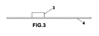
前述の図に示されるように、および指定された番号付けによれば、従来型構成から始めてどのようなものであるかが分かり、そこではアノード1は電流供給導体バー2と、少なくとも1つのコーティングされたまたは無コーティングのチタンアノードプレート4が取り付けられた一連の垂直配電バー3とに基づく、吊り下げ構造から構成され(本明細書の以下ではこれらを単にアノードプレートと呼ぶ)、図面の図1は実用的実施形態において、アノードがどのように2つのアノードプレート4を有するかを示す。従来型実施形態においてアノードプレート4は、図面の図2に示されるようにスポット溶接5によって垂直配電バー3に取り付けられる。
As shown in the aforementioned figure and according to the specified numbering, it can be seen how starting from a conventional configuration, the anode 1 has a current supply conductor bar 2 and at least one coating. It consists of a suspended structure based on a series of
上述の従来型構成から始めて本発明の第1の目的は、図4に示されるように少なくとも1つの電流制限器アセンブリ7を備えたアダプタ要素6の組み込みに基づき、それを通して対応する垂直配電バー3からアノードプレート4への電流供給または接続が確立される。
Starting from the conventional configuration described above, the first object of the invention is based on the incorporation of an
図4および5により1つの実用的実施形態において、アダプタ要素6は電流制限器アセンブリ7を備え、これは垂直配電バー3およびアノードプレート4に直接取り付けられ、その結果電流は垂直配電バー3から電流制限器7を通ってアノードプレートに到達する。この実施形態では電流制限器アセンブリ7自体が、アダプタ要素6として作用する。
In one practical embodiment according to FIGS. 4 and 5, the
さらに図面の図6および7によれば、実用的実施形態の第1の変形形態においてアダプタ要素6は、その一方の端部において垂直配電バー3に取り付けられ、他方の端部において電流制限器アセンブリ7を組み込む、チタンストリップ8によって定義され、一方、図面の図8によれば、実用的実施形態の第2の変形形態においてアダプタ要素6は、垂直配電バー3に取り付けられたチタンストリップ8から作られ、これは各端部に両方の電流制限器アセンブリ7を有し、それらにはそれぞれのアノードプレート4が取り付けられ、電流は垂直配電バー3からチタンストリップ8および対応する電流制限器7を通って、アノードプレート4に到達する。
Further according to figures 6 and 7 of the drawings, in a first variant of the practical embodiment the
電流制限器アセンブリは、自動リセット型であることが好ましく、当業界において入手可能な任意の機構を用いて具体化されることになり、すなわちバイメタルのブレーカ、自動リセットを有するデジタルヒューズ、自動リセットを有するアナログヒューズ、遮断または調節を有するトランジスタなどである。 The current limiter assembly is preferably of the self-resetting type and will be implemented using any mechanism available in the art, i.e., bimetallic breakers, digital fuses with automatic reset, digital fuses with automatic reset, etc. Analog fuses with, transistors with cut or adjust, etc.
例としておよび図面の図8、9、および10によれば以下のように述べることができ、アダプタ要素6の構成要素として用いられることになる電流制限器アセンブリ7の第1のタイプは、チタン/銅のバイメタルの部片9のペアによって定義され、銅表面は互いに対向し、それらの間に電流制限器10が挿入され、ポリマーの層および両側面上の銅のそれぞれのシートから構成され、互いに対向する両方のバイメタルの部片9の銅の幅に対応する横断する中央および周辺のくぼみを有し、くぼみはエポキシ樹脂11または同様の絶縁体によって満たされる。
By way of example and according to FIGS. 8, 9 and 10 of the drawings, it may be stated as follows that a first type of
このようにして図面の図8は、電流制限器アセンブリ7に関して以下を示し、2つの網掛けされた部分はバイメタルの部片9の銅に対応し、それらの周りの外形は、横断する中央および周辺のくぼみに対応するようになり、これは電流制限器10自体がそれらの間に挿入された2つのバイメタルの部片9に関連して、エポキシ樹脂11または他の絶縁材料によって満たされるようになる。
Figure 8 of the drawings thus shows the following with respect to the
図面の図11、12、および13による電流制限器アセンブリ7の第2のタイプは、チタンボックス12から構成されることができ、チタンストリップ8の一方の端部は挿入された絶縁材料13によって収容され、絶縁材料13は2つの電流制限器10をその中に組み込み、結果として好ましくは第2のタイプは図面の図13に示されるように、チタンストリップ8の各端部に1つずつ、2つのチタンボックス12を組み込み、これは端子によってチタンストリップ8に、および電流制限器10の他の端子によってチタンボックス12に接続され、言い換えれば電気の流れは垂直配電バー3 - チタンストリップ8 - 電流制限器10-チタンボックス12 - アノードプレート4となる。
A second type of
アダプタ当たり1つおよび2つの制限器によって表された場合に基づいて明らかであると考えられるので、アダプタ要素当たり3つ、4つなどの制限器への拡張についての説明を省いたことが留意される。 It is noted that we have omitted the discussion of extensions to three, four, etc. limiters per adapter element, as this is considered obvious based on the cases represented by one and two limiters per adapter. Ru.
絶縁材料13は、エポキシ樹脂もしくはプラスチック材料、または任意の他の等価な材料の層とすることができる。
Insulating
論理的に、アダプタ要素に関して述べられた構造は同様に、述べられたものと等価な他の実施形態を有することができ、従って図面の図14において以下がわかり、アダプタ要素6の一部を形成するチタンストリップ8は管状構成を有することができ、対応するアノードプレート4が取り付けられた直角に曲げられた第1のシート14に関連付けられて、その内側に完全に絶縁されて電流制限器10を収容することができる。同様に、各端部に1つずつ、直角に曲げられた2つのシート14が管状ストリップ8の内側から延び、対応するアノードプレート4が2つのシート14に取り付けられた二重構成も可能である。
Logically, the structure described with respect to the adapter element could likewise have other embodiments equivalent to the one described, so that in FIG. 14 of the drawings the following can be seen, forming part of the
同様に図15の実施形態によれば、アダプタ要素6の一部を形成する電流制限器自体は、チタンストリップ8上に挿入されたエポキシ樹脂のブロック15内に埋め込まれることができ、2つの部分に分割され、そのチタンストリップ8は、それをそれぞれのアノードプレート4に取り付けることができるように直角に曲げられる。前の場合のようにアダプタ要素は、それを2つのアノードプレート4に取り付けるように二重構成を有することができる。
Similarly, according to the embodiment of FIG. 15, the current limiter forming part of the
アノード1当たりの垂直配電バー3およびアノードプレート4の数は、本発明の目的に影響を及ぼさないが、これらの適切な数は設置の性能およびコストを調整することを可能にし、結果として要素の実用的な数は、3個の垂直バー、アノード当たり30個のアダプタ要素、ただし各1つは2つのアノードプレートに供給し、従ってアノード当たり合計60個のアノードプレートとなる。さらにアノードプレートは、250から1670cm2の面積を有する。
The number of
さらに従来型アノードにおいてアノードプレート4の数は1つまたは2つであり、結果として2つのプレートの場合、図面の図1に示されるように表面当たり1つ存在する。本発明の目的はこの従来型モデルに適用されることができるが、その有効性はアノード当たり、より大きな数のアノードプレート4が設置された場合に増加し、およびまたコストおよび設置の難しさは過度に高い値を妨げ、従ってそれら2つの間の妥協が確立される。
Furthermore, in conventional anodes the number of
我々は、他とは異なるアノードプレートを定義するアノード材料の面積を、両方の面積の間の電気抵抗が十分に高いことを条件に考慮し、それらの一方との陰極接触が確立されたとき、他方は動作の少なくとも30%程度その電気分解の過程を継続できるように、考慮する。 We consider the area of the anode material that defines the anode plate to be different from the other, provided that the electrical resistance between both areas is sufficiently high, and when a cathodic contact with one of them is established, The other is to allow the electrolysis process to continue for at least 30% of the operation.
各アダプタ要素6は少なくとも1つの電流制限器アセンブリ7を備えるようになり、これは短絡の場合に電流を遮断するまたは少なくともその電流を許容できる値に制限するようになり、許容できる値とはアノードの完全性に対して危険でなく、電流の大きな損失を示さない値と考えられる。我々は正常動作または公称電流と同様な値を推奨するが、公称動作電流の値の5倍を超えない短絡電流まで性能に著しい影響を及ぼさずに、より高い値によって動作させ得る。
Each
さらに本発明の第2の目的は、陽極電気分解によって生成される「酸ミスト」の放散を制御することを試みることである。これを行うために、図1に示されるような10から30mmの間だけ離れて間隔が置かれた2つの陽極プレート4に供給するアノードに対する、銅などの金属の電解採取のためのセルにおいて、図17、20、および21に示されるように、わずかな角度でアノードプレート4を配置することによって、アノードプレートの角度の結果として、矢印「A」に従って追従される経路を得ることによって、生成された気泡を制御し、経路付けることが可能であり、これは非常に多様な方法で得られることができる。
Furthermore, a second objective of the present invention is to attempt to control the dissipation of the "acid mist" produced by anodic electrolysis. To do this, in a cell for electrowinning of a metal such as copper, the anode feeds two
さらにアノードプレートの角度の大きさを変化させ、下から上に増加する角度によってそれらを配置することで、煙突効果を生じる逆さの魚骨形パターンでの配置が作成され、これは分散を避けることを可能にし、酸性気泡について、それらがアノードのアノードプレートの2つの側面の間で煙突内であるかのように制約され上昇するので、それらの制御された放散を可能にする。 Further varying the angular magnitude of the anode plates and arranging them with increasing angles from bottom to top creates an arrangement in an inverted fishbone pattern that creates a chimney effect, which avoids dispersion. and for acidic bubbles, allowing their controlled dissipation as they are constrained and rise as if in a chimney between the two sides of the anode plate of the anode.
アノードプレートの角度は、述べられたように種々の方法で達成されることができ、まず、第一に図面の図5の電流制限器アセンブリ7を備えたアダプタ要素6は、所望の角度で垂直配電バー3に直接取り付けられることができ、またはチタンストリップ8自体が所望の角度に従って、対応する垂直配電バー3に取り付けられることができ、または図17および18に示されるようにチタンストリップ8自体が捻られることができ、その端部は角度が付けられることができ、対応する電流制限器アセンブリが取り付けられたとき、チタンストリップ8に取り付けられたアノードプレートは所望の角度を有するようになる。
The angle of the anode plate can be achieved in various ways as mentioned, firstly the
上へ向かう気泡の流れをアノードの内側に集中させるこの現象は以下の利点をもたらす: This phenomenon of concentrating the upward flow of bubbles inside the anode provides the following benefits:
・ アノードとカソードとの間の電流の通過に対する電解質の抵抗の低減であり、なぜならアノードとカソードとの間の上へ向かう気泡は絶縁体であり、従ってそれらは電解質の実効的な抵抗を増加させるからである; - Reduction of the resistance of the electrolyte to the passage of current between the anode and cathode, since the upwardly directed air bubbles between the anode and cathode are insulators and therefore they increase the effective resistance of the electrolyte It is from;
・ カソードプレート上のより一様な銅堆積;アノードの下方部分でより高い電流密度があり、従って短絡のより高い発生率があり、言い換えれば下方部分上においてわずかに、より大きな銅の厚さがあることがよく知られている。上方部分に集中する気泡が、アノードとカソードとの間から阻止された場合、得られる銅プレートは、銅プレートの上方と下方部分の間の厚さの差がより小さく、より平坦となる; - More uniform copper deposition on the cathode plate; there is a higher current density and therefore a higher incidence of short circuits on the lower part of the anode, in other words a slightly larger copper thickness on the lower part. Something is well known. If the air bubbles concentrated in the upper part are blocked from between the anode and the cathode, the resulting copper plate will be flatter with a smaller difference in thickness between the upper and lower parts of the copper plate;
・ 金属の陰極堆積の過程の効率およびその品質に悪影響を及ぼす、これらの気泡がカソードに到達するようになり酸化を引き起こす可能性を低減する、および; reducing the likelihood that these air bubbles will reach the cathode and cause oxidation, which will adversely affect the efficiency of the process of cathodic deposition of metal and its quality; and;
・ 大きな割合の酸性気泡が2つの陽極表面の狭い内部領域を通って上昇するとき、煙突の出口における捕集器の設置は、「酸ミスト」の非常に効果的な捕集を可能にし、結果として環境汚染を著しく低減する。 - The installation of a collector at the exit of the chimney allows a very effective collection of the "acid mist" when a large proportion of acid bubbles rises through the narrow internal area of the two anode surfaces, resulting in This significantly reduces environmental pollution.
さらに図面の図22および23に示される1つの実用的実施形態において、電流制限器アセンブリ(7)は、絶縁材料(13)を含んだボックス(12)である少なくとも1つの外枠と、チタンストリップ(8)である少なくとも1つの内枠とを備え、少なくとも1つの内枠は少なくとも1つの外枠内に部分的にまたは完全に収容され、少なくとも1つの外枠および少なくとも1つの内枠は、少なくとも1つの内枠が取り付けられ、1つまたは複数の垂直配電バー(3)の少なくとも1つの一部分を部分的に包むように、U字形輪郭を有し、少なくとも1つの外枠は少なくとも1つのアノードプレート(4)に関連付けられまたは取り付けられる。
In one practical embodiment, further illustrated in Figures 22 and 23 of the drawings, the current limiter assembly (7) comprises at least one outer shell that is a box (12) containing an insulating material (13) and a titanium strip. (8) wherein the at least one inner frame is partially or completely contained within the at least one outer frame , and the at least one outer frame and the at least one inner frame are at least One inner frame is mounted and has a U-shaped profile so as to partially enclose at least a portion of the one or more vertical distribution bars (3), and the at least one outer frame is fitted with at least one anode plate (3). 4) associated with or attached to.
この実施形態は、アダプタ要素の生産を簡単にし、生産コストを低減する利点を有する。実際、実施形態は、本発明によるアダプタ要素の製造、統合、および電気効率の観点からの改善をもたらすことができる。製造に関して、チタンストリップ(8)およびボックス(12)のU字形輪郭は、アダプタ要素を組み立てるために必要なチタンの量を効率的に管理および/または低減することを可能にする。容器は、2つのU字輪郭から、一方を他方の内側に配置することによって構築され、これらの輪郭は長いストリップにおいて自動的に、および溶接および難しい切断を必要とせずに折り畳み機を用いて高い効率で製造される。加えて電流制限器のリード線を溶接することは、ずっと快適におよび効率的に行われ、それ自体はロボット化されたプロセスに適し、これは非常に競争力のあるコストでの、高い製造能力を意味する。最後に電気効率に関して、電流配電バーをアダプタ自体で包み込むまたは取り囲むことによって、電流経路はアダプタの面に垂直となり、これは最大の断面および回路の最小の長さを意味することが考慮されるべきである。 This embodiment has the advantage of simplifying the production of the adapter element and reducing production costs. Indeed, embodiments may provide improvements in terms of manufacturing, integration, and electrical efficiency of adapter elements according to the invention. Regarding manufacturing, the U-shaped profile of the titanium strip (8) and box (12) makes it possible to efficiently manage and/or reduce the amount of titanium required to assemble the adapter elements. The container is constructed from two U-shaped profiles by placing one inside the other, and these profiles are folded automatically in long strips and with the help of a folding machine without the need for welding and difficult cutting. Manufactured with efficiency. In addition welding current limiter leads is much more comfortable and efficient and is itself suitable for robotized processes, which allows for high manufacturing capacity at very competitive costs. means. Finally regarding electrical efficiency, it should be taken into account that by wrapping or surrounding the current distribution bar with the adapter itself, the current path will be perpendicular to the plane of the adapter, which means a maximum cross section and a minimum length of the circuit. It is.
本明細書で前に述べられた実施形態は、望むならば、煙突効果を可能にする構成において用いられることができる。このような場合アノードプレートが、アノードにおいて行われる電気化学反応からのガス気泡の流れを方向付けるように、垂直位置に対して傾きまたは曲がりを有して搭載されることになる。例えばアノードプレートは、積分記号「∫」のような、またはこの目的にために適切であると当業者なら容易に認識するであろう任意の他の形状に成形されるように曲げられる。あるいはアノードプレートとアダプタ要素との間に、垂直方向に対してある角度でアノードプレートを溶接することを可能にする導電性くさびまたはシェーパーを差し込むことが可能である。 The embodiments previously described herein can be used in configurations that allow for a chimney effect, if desired. In such cases the anode plate will be mounted with an inclination or bend relative to the vertical position so as to direct the flow of gas bubbles from the electrochemical reaction taking place at the anode. For example, the anode plate can be bent to form an integral symbol "∫" or any other shape that one skilled in the art would readily recognize as suitable for this purpose. Alternatively, it is possible to insert a conductive wedge or shaper between the anode plate and the adapter element, which makes it possible to weld the anode plate at an angle to the vertical direction.
最後に、本発明はさらに以下の実施形態A~Kに関する: Finally, the invention further relates to the following embodiments A to K:
A)吊り下げ構造から構成される垂直アノードのタイプの電気化学セルのための安全なアノードであって、
- 水平電流供給導体バーと、
- 電流供給バーに接続された垂直配電バーであって、
・銅またはアルミニウムコア、および
・チタン外層または外皮
によって定義された配電バーと、
- コーティングされ、垂直配電バーに関連付けられた少なくとも1つのチタンアノードプレートと
に基づき、安全なアノード(1)は、垂直配電バー(3)の少なくとも1つと少なくとも1つのコーティングされたチタンアノードプレート(4)との間に配置された安全アノードアダプタ要素(6)を組み込み、そのアダプタ要素(6)は電流制限器(10)がその中に一体化された少なくとも1つの電流制限器アセンブリ(7)を備え、これは垂直配電バー(3)およびコーティングされたチタンアノードプレート(4)に関連付けられ、垂直配電バー(3)をコーティングされたチタンアノードプレート(4)に接続することを特徴とする、電気化学セルのための安全なアノード。
A) A safe anode for an electrochemical cell of the type of vertical anode consisting of a suspended structure, comprising:
- a horizontal current supply conductor bar;
- a vertical distribution bar connected to a current supply bar,
a distribution bar defined by a copper or aluminum core, and a titanium outer layer or skin;
- at least one titanium anode plate coated and associated with the vertical distribution bar; the safe anode (1) is based on at least one of the vertical distribution bars (3) and at least one coated titanium anode plate (4); ), the adapter element (6) incorporating at least one current limiter assembly (7) with a current limiter (10) integrated therein. an electrical device, characterized in that it is associated with a vertical distribution bar (3) and a coated titanium anode plate (4), connecting the vertical distribution bar (3) to the coated titanium anode plate (4). Safe anode for chemical cells.
B)項目Aの実施形態による電気化学セルのための安全なアノードであって、安全なアノードのアダプタ要素(6)は、電流制限器(10)がその中に一体化され、垂直配電バー(3)およびコーティングされたチタンアノードプレート(4)に取り付けられた、電流制限器アセンブリ(7)によって定義されることを特徴とする、電気化学セルのための安全なアノード。 B) A safe anode for an electrochemical cell according to an embodiment of item A, wherein the adapter element (6) of the safe anode has a current limiter (10) integrated therein and a vertical distribution bar ( 3) and a safe anode for electrochemical cells, characterized in that it is defined by a current limiter assembly (7) attached to a coated titanium anode plate (4).
C)項目Aの実施形態による電気化学セルのための安全なアノードであって、安全なアノードのアダプタ要素(6)は、少なくとも1つの電流制限器アセンブリ(7)を保持するチタンストリップ(8)によって定義され、チタンストリップ(8)は垂直配電バー(3)に取り付けられ、対応するコーティングされたチタンアノードプレート(4)は電流制限器アセンブリ(7)に取り付けられることを特徴とする、電気化学セルのための安全なアノード。 C) A safe anode for an electrochemical cell according to an embodiment of item A, wherein the adapter element (6) of the safe anode comprises a titanium strip (8) carrying at least one current limiter assembly (7). , characterized in that the titanium strip (8) is attached to the vertical distribution bar (3) and the corresponding coated titanium anode plate (4) is attached to the current limiter assembly (7). Safe anode for cells.
D)項目AおよびCの実施形態による電気化学セルのための安全なアノードであって、安全なアノードのアダプタ要素(6)は、各端部に1つずつ、2つの電流制限器アセンブリ(7)を保持するチタンストリップ(8)によって定義され、チタンストリップ(8)は垂直配電バー(3)に取り付けられ、対応するコーティングされたチタンアノードプレート(4)は電流制限器アセンブリ(7)のペアに取り付けられることを特徴とする、電気化学セルのための安全なアノード。 D) A safe anode for an electrochemical cell according to embodiments of items A and C, wherein the adapter element (6) of the safe anode comprises two current limiter assemblies (7), one at each end. ), the titanium strip (8) is attached to the vertical distribution bar (3) and the corresponding coated titanium anode plate (4) is defined by a pair of current limiter assemblies (7). A safe anode for electrochemical cells, characterized in that it is attached to.
E)項目Aの実施形態による電気化学セルのための安全なアノードであって、少なくとも1つの電流制限器アセンブリ(7)を備えた安全なアノードのアダプタ要素(6)は、対応する垂直配電バー(3)に取り付けられ、垂直平面に対してわずかな角度を定義し、アダプタ要素(6)に取り付けられたコーティングされたチタンアノードプレート(4)は同じ角度を有することを特徴とする、電気化学セルのための安全なアノード。 E) A safe anode for an electrochemical cell according to the embodiment of item A, wherein the adapter element (6) of the safe anode with at least one current limiter assembly (7) is connected to a corresponding vertical distribution bar. (3), defining a slight angle with respect to the vertical plane, and characterized in that the coated titanium anode plate (4), attached to the adapter element (6), has the same angle. Safe anode for cells.
F)項目Eの実施形態による電気化学セルのための安全なアノードであって、少なくとも1つの電流制限器アセンブリ(7)を備えたアノードのアダプタ要素(6)は、それらのわずかな搭載角度において異なる大きさを有することができ、それらに関連付けられたアノードプレート(4)も、垂直平面に対して異なる角度に応じて角度が付けられることを特徴とする、電気化学セルのための安全なアノード。 F) Safe anode for an electrochemical cell according to the embodiment of item E, in which the adapter element (6) of the anode with at least one current limiter assembly (7) is Safe anode for electrochemical cells, characterized in that they can have different sizes and that the anode plates (4) associated with them are also angled according to different angles with respect to the vertical plane .
G)項目Fの実施形態による電気化学セルのための安全なアノードであって、少なくとも1つの電流制限器アセンブリ(7)を備え、それらのわずかな搭載角度において異なる大きさを有するアノードのアダプタ要素(6)は、対応する第2の垂直配電バー(3)に沿って、下から上へ増加する大きさを有して取り付けられ、煙突効果を引き起こすことを特徴とする、電気化学セルのための安全なアノード。 G) Safe anode for an electrochemical cell according to the embodiment of item F, comprising at least one current limiter assembly (7) and adapter elements of the anode having different sizes in their slight mounting angle. (6) for an electrochemical cell, characterized in that it is installed along the corresponding second vertical distribution bar (3) with increasing magnitude from bottom to top, causing a chimney effect. safe anode.
H)項目Cの実施形態による電気化学セルのための安全なアノードであって、アダプタ要素(6)の一部を形成するチタンストリップ(8)は管状構成を有し、直角に曲げられ少なくとも1つのシート(14)に関連付けられたその中央内部部分に電流制限器(10)を組み込み、シート(14)は外側に延び、対応するアノードプレート(4)がシート(14)に取り付けられることを特徴とする、電気化学セルのための安全なアノード。 H) Safe anode for an electrochemical cell according to the embodiment of item C, in which the titanium strip (8) forming part of the adapter element (6) has a tubular configuration, is bent at right angles and has at least one incorporating a current limiter (10) in its central inner part associated with one sheet (14), the sheets (14) extending outwardly and characterized in that a corresponding anode plate (4) is attached to the sheet (14). A safe anode for electrochemical cells.
I)項目Cの実施形態による電気化学セルのための安全なアノードであって、アダプタ要素(6)の一部を形成するチタンストリップ(8)は、その上に挿入されたエポキシ樹脂または同様の材料のブロック(15)を有し、その中に電流制限器(10)が埋め込まれることを特徴とする、電気化学セルのための安全なアノード。 I) Safe anode for an electrochemical cell according to the embodiment of item C, in which the titanium strip (8) forming part of the adapter element (6) is made of an epoxy or similar material inserted thereon. Safe anode for an electrochemical cell, characterized in that it has a block (15) of material, in which a current limiter (10) is embedded.
J)項目Aの実施形態による電気化学セルのための安全なアノードであって、アダプタ要素(6)の一部を形成し、電流制限器(10)がその中に一体化される電流制限器アセンブリ(7)は、チタンストリップ(8)を収容したボックス(12)によって定義され、チタンストリップ(8)はそれを含んだボックス(12)の絶縁材料(13)によって絶縁され、その絶縁材料(13)は、端子によって中間チタンストリップ(8)に、および他方の端子によってボックス(12)に接続された2つの電流制限器(10)を組み込むことを特徴とする、電気化学セルのための安全なアノード。 J) A safe anode for an electrochemical cell according to an embodiment of item A, a current limiter forming part of the adapter element (6) and in which the current limiter (10) is integrated. The assembly (7) is defined by a box (12) containing a titanium strip (8), which is insulated by the insulating material (13) of the box (12) containing it and which insulating material ( 13) Safety for electrochemical cells, characterized in that it incorporates two current limiters (10) connected by a terminal to the intermediate titanium strip (8) and by the other terminal to the box (12) anode.
K)項目Aの実施形態による電気化学セルのための安全なアノードであって、アダプタ要素(6)の一部を形成し、電流制限器(10)がその中に一体化された電流制限器アセンブリ(7)は、バイメタルのチタン/銅の部片(9)のペアによって定義され、銅表面は互いに対向し、それらの間に電流制限器(10)が挿入され、ポリマー層および両側面上の銅のそれぞれの層から構成され、両方の相対するバイメタルの部片(9)の銅の幅に対応する横断する中央および周辺のくぼみを有し、くぼみはエポキシ樹脂(11)または同様の絶縁体によって満たされることを特徴とする、電気化学セルのための安全なアノード。 K) A safe anode for an electrochemical cell according to an embodiment of item A, forming part of the adapter element (6) and having a current limiter (10) integrated therein. The assembly (7) is defined by a pair of bimetallic titanium/copper pieces (9), the copper surfaces facing each other, a current limiter (10) inserted between them, a polymer layer and on both sides of copper, with a transverse central and peripheral recess corresponding to the width of the copper of both opposing bimetallic pieces (9), the recess being insulated with epoxy resin (11) or similar insulation. Safe anode for electrochemical cells, characterized by being filled by the body.
Claims (13)
- 水平電流供給導体バーと、
- 水平電流供給導体バーに接続された1つまたは複数の垂直配電バーであって、
・ 銅、アルミニウム、鉛、およびそれらの合金からなる群から選択された導電性要素のコア、ならびに
・ チタンまたはその合金、バルブ金属またはその合金、および鉛またはその合金からなる群から選択された材料の外層または外皮
を備えた垂直配電バーと、
- 垂直配電バーに取り付けられた少なくとも1つのコーティングされたまたは無コーティングのチタンアノードプレートと
を有する電気化学セルのためのアノードにおいて、
アノード(1)は、垂直配電バー(3)の少なくとも1つとコーティングされたまたは無コーティングのチタンアノードプレート(4)の少なくとも1つとの間に配置されたアダプタ要素(6)を組み込み、
アダプタ要素(6)は電流制限器(10)を有する少なくとも1つの電流制限器アセンブリ(7)を備え、
前記電流制限器アセンブリ(7)は、垂直配電バー(3)をコーティングされたまたは無コーティングのチタンアノードプレート(4)に接続するように、少なくとも1つの垂直配電バー(3)および少なくとも1つのコーティングされたまたは無コーティングのチタンアノードプレート(4)に取り付けられることを特徴とする、
電気化学セルのためのアノード。 An anode for an electrochemical cell of the type of vertical anode with a hanging structure, the anode comprising:
- a horizontal current supply conductor bar;
- one or more vertical distribution bars connected to horizontal current supply conductor bars,
- a core of an electrically conductive element selected from the group consisting of copper, aluminium, lead and alloys thereof, and - a material selected from the group consisting of titanium or its alloys, valve metal or its alloys, and lead or its alloys. a vertical distribution bar with an outer layer or skin;
- at least one coated or uncoated titanium anode plate mounted on a vertical distribution bar;
The anode (1) incorporates an adapter element (6) arranged between at least one of the vertical distribution bars (3) and at least one of the coated or uncoated titanium anode plates (4);
The adapter element (6) comprises at least one current limiter assembly (7) having a current limiter (10);
Said current limiter assembly (7) comprises at least one vertical distribution bar (3) and at least one coating so as to connect the vertical distribution bar (3) to a coated or uncoated titanium anode plate (4). attached to a coated or uncoated titanium anode plate (4),
Anode for electrochemical cells.
前記電流制限器アセンブリ(7)に取り付けられた前記チタンアノードプレート(4)も同じ角度を有するように、各アダプタ要素(6)が、前記垂直配電バー(3)の垂直平面に対して3.25度以下の角度を定義する前記垂直配電バー(3)に取り付けられ、
各アダプタ要素(6)が異なる大きさを有する、請求項5に記載の電気化学セルのためのアノード。 said anode comprises two or more adapter elements (6);
3. Each adapter element (6) is angled relative to the vertical plane of the vertical distribution bar (3) so that the titanium anode plate (4) attached to the current limiter assembly (7) also has the same angle. attached to said vertical distribution bar (3) defining an angle of 25 degrees or less;
Anode for an electrochemical cell according to claim 5, wherein each adapter element (6) has a different size.
バイメタルのチタン/銅の部片(9)のペアの銅表面が互いに対向し、それらの間に電流制限器(10)が挿入され、
両方の相対するバイメタルの部片(9)の幅に対応する横方向において、中央および両端にくぼみが存在し、
前記くぼみはエポキシ樹脂(11)または絶縁体によって満たされる、請求項1に記載の電気化学セルのためのアノード。 the current limiter assembly (7) comprises a pair of bimetallic titanium/copper pieces (9);
the copper surfaces of the pair of bimetallic titanium/copper pieces (9) are opposite each other and a current limiter (10) is inserted between them;
a recess is present in the center and at both ends in the lateral direction corresponding to the width of both opposing bimetallic pieces (9);
Anode for an electrochemical cell according to claim 1, wherein the recess is filled with an epoxy resin (11) or an insulator.
前記少なくとも1つの内枠が前記少なくとも1つの外枠内に部分的にまたは完全に収容され、
前記少なくとも1つの内枠が取り付けられ、且つ前記1つまたは複数の垂直配電バー(3)の少なくとも1つの一部分を部分的に包むように、前記少なくとも1つの外枠及び少なくとも1つの内枠がU字形輪郭を有し、
前記少なくとも1つの外枠は少なくとも1つのアノードプレート(4)に取り付けられる、請求項9に記載の電気化学セルのためのアノード。 The current limiter assembly (7) comprises at least one outer frame that is a box (12) containing an insulating material (13) and at least one inner frame that is a titanium strip (8);
the at least one inner frame is partially or completely housed within the at least one outer frame ;
The at least one outer frame and the at least one inner frame are U-shaped, such that the at least one inner frame is attached and partially encloses a portion of at least one of the one or more vertical power distribution bars (3). has a contour,
Anode for an electrochemical cell according to claim 9 , wherein the at least one outer frame is attached to at least one anode plate (4).
13. The electrochemical cell of claim 12 , wherein the metal is a non-ferrous metal.
Priority Applications (1)
| Application Number | Priority Date | Filing Date | Title |
|---|---|---|---|
| JP2022140482A JP2022184865A (en) | 2016-04-29 | 2022-09-05 | Safe anode for electrochemical cells |
Applications Claiming Priority (3)
| Application Number | Priority Date | Filing Date | Title |
|---|---|---|---|
| ESP201630554 | 2016-04-29 | ||
| ES201630554A ES2580552B1 (en) | 2016-04-29 | 2016-04-29 | SAFE ANODE FOR ELECTROCHEMICAL CELL |
| PCT/IB2017/052403 WO2017187357A1 (en) | 2016-04-29 | 2017-04-26 | Safe anode for electrochemical cells |
Related Child Applications (1)
| Application Number | Title | Priority Date | Filing Date |
|---|---|---|---|
| JP2022140482A Division JP2022184865A (en) | 2016-04-29 | 2022-09-05 | Safe anode for electrochemical cells |
Publications (3)
| Publication Number | Publication Date |
|---|---|
| JP2019516019A JP2019516019A (en) | 2019-06-13 |
| JPWO2017187357A5 JPWO2017187357A5 (en) | 2023-08-22 |
| JP7399619B2 true JP7399619B2 (en) | 2023-12-18 |
Family
ID=56692749
Family Applications (2)
| Application Number | Title | Priority Date | Filing Date |
|---|---|---|---|
| JP2018556386A Active JP7399619B2 (en) | 2016-04-29 | 2017-04-26 | Safe anode for electrochemical cells |
| JP2022140482A Pending JP2022184865A (en) | 2016-04-29 | 2022-09-05 | Safe anode for electrochemical cells |
Family Applications After (1)
| Application Number | Title | Priority Date | Filing Date |
|---|---|---|---|
| JP2022140482A Pending JP2022184865A (en) | 2016-04-29 | 2022-09-05 | Safe anode for electrochemical cells |
Country Status (21)
| Country | Link |
|---|---|
| US (1) | US10590554B2 (en) |
| EP (1) | EP3449043B1 (en) |
| JP (2) | JP7399619B2 (en) |
| KR (1) | KR102485531B1 (en) |
| CN (1) | CN108713074B (en) |
| AR (1) | AR108239A1 (en) |
| AU (1) | AU2017257423B2 (en) |
| BR (1) | BR112018071888B1 (en) |
| CA (1) | CA3013419A1 (en) |
| CL (1) | CL2018003012A1 (en) |
| EA (1) | EA201892472A1 (en) |
| ES (2) | ES2580552B1 (en) |
| HK (1) | HK1258149A1 (en) |
| MA (1) | MA45333A (en) |
| MX (1) | MX2018013045A (en) |
| PE (1) | PE20181866A1 (en) |
| PH (1) | PH12018502224A1 (en) |
| PL (1) | PL3449043T3 (en) |
| TW (1) | TWI714763B (en) |
| WO (1) | WO2017187357A1 (en) |
| ZA (1) | ZA201805017B (en) |
Families Citing this family (6)
| Publication number | Priority date | Publication date | Assignee | Title |
|---|---|---|---|---|
| US10665849B2 (en) * | 2017-03-20 | 2020-05-26 | The Boeing Company | Battery cell design for preventing internal short circuits from occurring and propagating |
| US10651514B2 (en) | 2017-03-20 | 2020-05-12 | The Boeing Company | Battery cell design for preventing internal short circuits from occurring and propagating using positive temperature coefficient (PTC) materials |
| EP3748042A1 (en) * | 2019-06-03 | 2020-12-09 | Permascand Ab | Electrode assembly for electrochemical processes and method of restoring the same |
| EP3748041A1 (en) * | 2019-06-03 | 2020-12-09 | Permascand Ab | An electrode assembly for electrochemical processes |
| CN110158117A (en) * | 2019-06-26 | 2019-08-23 | 中国恩菲工程技术有限公司 | Combined type copper electrolysis anode |
| CN110904467B (en) * | 2019-12-27 | 2023-06-27 | 昆明理工大学 | Assembled anode for synthesizing stannous octoate through electrochemical reaction and assembling method |
Citations (3)
| Publication number | Priority date | Publication date | Assignee | Title |
|---|---|---|---|---|
| US5679240A (en) | 1995-07-12 | 1997-10-21 | Metallgesellschaft Aktiengesellschaft | Anode for the electrolytic winning of metals and process |
| JP2013014815A (en) | 2011-07-06 | 2013-01-24 | Toshiba Corp | Household electrical appliance |
| WO2015079072A2 (en) | 2014-02-19 | 2015-06-04 | Industrie De Nora S.P.A. | Anode structure for metal electrowinning cells |
Family Cites Families (12)
| Publication number | Priority date | Publication date | Assignee | Title |
|---|---|---|---|---|
| US4512866A (en) | 1983-10-04 | 1985-04-23 | Langley Robert C | Titanium-lead anode for use in electrolytic processes employing sulfuric acid |
| DE3406777C2 (en) * | 1984-02-24 | 1985-12-19 | Conradty GmbH & Co Metallelektroden KG, 8505 Röthenbach | Coated valve metal anode for the electrolytic extraction of metals or metal oxides |
| JP3539015B2 (en) * | 1995-11-30 | 2004-06-14 | 日産自動車株式会社 | Electrolytic etching method |
| US6245209B1 (en) * | 1999-01-15 | 2001-06-12 | Jacobs Bill | Electro-refining system and method |
| US7927468B2 (en) | 2008-08-27 | 2011-04-19 | GM Global Technology Operations LLC | Electrode assembly for use in an electrodeposition process |
| US8038855B2 (en) * | 2009-04-29 | 2011-10-18 | Freeport-Mcmoran Corporation | Anode structure for copper electrowinning |
| ITMI20111668A1 (en) * | 2011-09-16 | 2013-03-17 | Industrie De Nora Spa | PERMANENT SYSTEM FOR THE CONTINUOUS EVALUATION OF THE CURRENT DISTRIBUTION IN INTERCONNECTED ELECTROLYTIC CELLS. |
| ITMI20111938A1 (en) * | 2011-10-26 | 2013-04-27 | Industrie De Nora Spa | ANODIC COMPARTMENT FOR CELLS FOR ELECTROLYTIC EXTRACTION OF METALS |
| US20160010233A1 (en) * | 2012-02-10 | 2016-01-14 | Outotec Oyj | System for power control in cells for electrolytic recovery of a metal |
| WO2014032085A1 (en) * | 2012-08-28 | 2014-03-06 | Hatch Associates Pty Limited | Improved electric current sensing and management system for electrolytic plants |
| ITMI20130505A1 (en) * | 2013-04-04 | 2014-10-05 | Industrie De Nora Spa | CELL FOR ELECTROLYTIC EXTRACTION OF METALS |
| CL2014001133A1 (en) * | 2014-04-30 | 2014-11-03 | Propipe Maqunarias Limitada | Insertable (dei) electrode device that replaces the traditional anode in electro-metal processes, which does not generate acid mist or other gases, comprising a perimeter frame arranged on both sides of the device, ion exchange membranes, strategic electrode that is a conductor or semiconductor, inlet and outlet duct, vertical electric busbars; device application procedure. |
-
2016
- 2016-04-29 ES ES201630554A patent/ES2580552B1/en active Active
-
2017
- 2017-04-24 MA MA045333A patent/MA45333A/en unknown
- 2017-04-26 CA CA3013419A patent/CA3013419A1/en active Pending
- 2017-04-26 BR BR112018071888-2A patent/BR112018071888B1/en active IP Right Grant
- 2017-04-26 JP JP2018556386A patent/JP7399619B2/en active Active
- 2017-04-26 WO PCT/IB2017/052403 patent/WO2017187357A1/en active Application Filing
- 2017-04-26 EP EP17720233.0A patent/EP3449043B1/en active Active
- 2017-04-26 AU AU2017257423A patent/AU2017257423B2/en active Active
- 2017-04-26 EA EA201892472A patent/EA201892472A1/en unknown
- 2017-04-26 MX MX2018013045A patent/MX2018013045A/en unknown
- 2017-04-26 ES ES17720233T patent/ES2743198T3/en active Active
- 2017-04-26 PE PE2018002069A patent/PE20181866A1/en unknown
- 2017-04-26 KR KR1020187034467A patent/KR102485531B1/en active IP Right Grant
- 2017-04-26 US US16/076,559 patent/US10590554B2/en active Active
- 2017-04-26 PL PL17720233T patent/PL3449043T3/en unknown
- 2017-04-26 CN CN201780015229.4A patent/CN108713074B/en active Active
- 2017-04-27 AR ARP170101081A patent/AR108239A1/en active IP Right Grant
- 2017-04-28 TW TW106114355A patent/TWI714763B/en active
-
2018
- 2018-07-25 ZA ZA2018/05017A patent/ZA201805017B/en unknown
- 2018-10-18 PH PH12018502224A patent/PH12018502224A1/en unknown
- 2018-10-24 CL CL2018003012A patent/CL2018003012A1/en unknown
-
2019
- 2019-01-14 HK HK19100503.9A patent/HK1258149A1/en unknown
-
2022
- 2022-09-05 JP JP2022140482A patent/JP2022184865A/en active Pending
Patent Citations (3)
| Publication number | Priority date | Publication date | Assignee | Title |
|---|---|---|---|---|
| US5679240A (en) | 1995-07-12 | 1997-10-21 | Metallgesellschaft Aktiengesellschaft | Anode for the electrolytic winning of metals and process |
| JP2013014815A (en) | 2011-07-06 | 2013-01-24 | Toshiba Corp | Household electrical appliance |
| WO2015079072A2 (en) | 2014-02-19 | 2015-06-04 | Industrie De Nora S.P.A. | Anode structure for metal electrowinning cells |
Also Published As
| Publication number | Publication date |
|---|---|
| BR112018071888A2 (en) | 2019-02-05 |
| MA45333A (en) | 2019-03-06 |
| TWI714763B (en) | 2021-01-01 |
| MX2018013045A (en) | 2019-01-24 |
| WO2017187357A1 (en) | 2017-11-02 |
| CN108713074A (en) | 2018-10-26 |
| JP2022184865A (en) | 2022-12-13 |
| KR20190002616A (en) | 2019-01-08 |
| CN108713074B (en) | 2021-02-05 |
| KR102485531B1 (en) | 2023-01-09 |
| PL3449043T3 (en) | 2019-12-31 |
| EP3449043B1 (en) | 2019-07-03 |
| HK1258149A1 (en) | 2019-11-08 |
| BR112018071888B1 (en) | 2023-03-21 |
| ES2743198T3 (en) | 2020-02-18 |
| AU2017257423A1 (en) | 2018-08-16 |
| AU2017257423B2 (en) | 2021-11-25 |
| ZA201805017B (en) | 2019-09-25 |
| CL2018003012A1 (en) | 2019-02-01 |
| JP2019516019A (en) | 2019-06-13 |
| TW201809360A (en) | 2018-03-16 |
| AR108239A1 (en) | 2018-08-01 |
| CA3013419A1 (en) | 2017-11-02 |
| ES2580552A1 (en) | 2016-08-24 |
| US20190048485A1 (en) | 2019-02-14 |
| EA201892472A1 (en) | 2019-04-30 |
| EP3449043A1 (en) | 2019-03-06 |
| US10590554B2 (en) | 2020-03-17 |
| PE20181866A1 (en) | 2018-12-04 |
| ES2580552B1 (en) | 2017-05-31 |
| PH12018502224A1 (en) | 2019-08-05 |
Similar Documents
| Publication | Publication Date | Title |
|---|---|---|
| JP7399619B2 (en) | Safe anode for electrochemical cells | |
| JP2013073929A (en) | Battery pack | |
| US9899684B2 (en) | Electrodes, batteries, electrode production methods, and battery production methods | |
| JP6270694B2 (en) | Fuel cell stack | |
| JP2695908B2 (en) | Assembled anodes as mosaics of modular anodes | |
| PL136045B1 (en) | Electrode,in particular anode of plated valve metal,for electrolytically obtaining a metal or its oxides | |
| US11710613B2 (en) | Melting conductor and fuse | |
| JPH05106075A (en) | Insoluble anode for electrolysis in aqueous solution | |
| JPWO2017187357A5 (en) | ||
| ES2855699T3 (en) | Electrode structure provided with resistors | |
| US2434731A (en) | Platinum sheet electrode | |
| CN109891003B (en) | Improvement of hanger rod | |
| JP5488281B2 (en) | Molten salt battery and molten salt battery | |
| CN108963174A (en) | Battery conductive connection sheet and full tab core | |
| JP2015104186A (en) | Electric connection box | |
| IT9021410A1 (en) | INSOLUBLE ANODE FOR ELECTROLYSIS IN AQUEOUS SOLUTIONS. |
Legal Events
| Date | Code | Title | Description |
|---|---|---|---|
| A621 | Written request for application examination |
Free format text: JAPANESE INTERMEDIATE CODE: A621 Effective date: 20200326 |
|
| A977 | Report on retrieval |
Free format text: JAPANESE INTERMEDIATE CODE: A971007 Effective date: 20201125 |
|
| A131 | Notification of reasons for refusal |
Free format text: JAPANESE INTERMEDIATE CODE: A131 Effective date: 20210105 |
|
| A521 | Request for written amendment filed |
Free format text: JAPANESE INTERMEDIATE CODE: A523 Effective date: 20210331 |
|
| A131 | Notification of reasons for refusal |
Free format text: JAPANESE INTERMEDIATE CODE: A131 Effective date: 20210824 |
|
| A601 | Written request for extension of time |
Free format text: JAPANESE INTERMEDIATE CODE: A601 Effective date: 20211124 |
|
| A521 | Request for written amendment filed |
Free format text: JAPANESE INTERMEDIATE CODE: A523 Effective date: 20220124 |
|
| A02 | Decision of refusal |
Free format text: JAPANESE INTERMEDIATE CODE: A02 Effective date: 20220510 |
|
| C60 | Trial request (containing other claim documents, opposition documents) |
Free format text: JAPANESE INTERMEDIATE CODE: C60 Effective date: 20220905 |
|
| A521 | Request for written amendment filed |
Free format text: JAPANESE INTERMEDIATE CODE: A523 Effective date: 20220915 |
|
| C22 | Notice of designation (change) of administrative judge |
Free format text: JAPANESE INTERMEDIATE CODE: C22 Effective date: 20221108 |
|
| C22 | Notice of designation (change) of administrative judge |
Free format text: JAPANESE INTERMEDIATE CODE: C22 Effective date: 20230221 |
|
| C22 | Notice of designation (change) of administrative judge |
Free format text: JAPANESE INTERMEDIATE CODE: C22 Effective date: 20230411 |
|
| A524 | Written submission of copy of amendment under article 19 pct |
Free format text: JAPANESE INTERMEDIATE CODE: A524 Effective date: 20230807 |
|
| A61 | First payment of annual fees (during grant procedure) |
Free format text: JAPANESE INTERMEDIATE CODE: A61 Effective date: 20231206 |
|
| R150 | Certificate of patent or registration of utility model |
Ref document number: 7399619 Country of ref document: JP Free format text: JAPANESE INTERMEDIATE CODE: R150 |