JP7398888B2 - U-based fasteners with folded barbs and multiple spring arms - Google Patents
U-based fasteners with folded barbs and multiple spring arms Download PDFInfo
- Publication number
- JP7398888B2 JP7398888B2 JP2019109298A JP2019109298A JP7398888B2 JP 7398888 B2 JP7398888 B2 JP 7398888B2 JP 2019109298 A JP2019109298 A JP 2019109298A JP 2019109298 A JP2019109298 A JP 2019109298A JP 7398888 B2 JP7398888 B2 JP 7398888B2
- Authority
- JP
- Japan
- Prior art keywords
- aperture
- spring arm
- barb
- fastener
- rib
- Prior art date
- Legal status (The legal status is an assumption and is not a legal conclusion. Google has not performed a legal analysis and makes no representation as to the accuracy of the status listed.)
- Active
Links
- 238000003780 insertion Methods 0.000 claims description 108
- 230000037431 insertion Effects 0.000 claims description 108
- 230000014759 maintenance of location Effects 0.000 claims description 40
- 239000000463 material Substances 0.000 claims description 11
- 230000002093 peripheral effect Effects 0.000 claims 10
- 230000008878 coupling Effects 0.000 claims 3
- 238000010168 coupling process Methods 0.000 claims 3
- 238000005859 coupling reaction Methods 0.000 claims 3
- 238000000034 method Methods 0.000 description 3
- 229910000639 Spring steel Inorganic materials 0.000 description 2
- 230000001154 acute effect Effects 0.000 description 2
- 230000013011 mating Effects 0.000 description 2
- 229910045601 alloy Inorganic materials 0.000 description 1
- 239000000956 alloy Substances 0.000 description 1
- 238000005452 bending Methods 0.000 description 1
- 230000000295 complement effect Effects 0.000 description 1
- 239000002131 composite material Substances 0.000 description 1
- 238000010276 construction Methods 0.000 description 1
- 210000003195 fascia Anatomy 0.000 description 1
- 230000002452 interceptive effect Effects 0.000 description 1
- 238000003698 laser cutting Methods 0.000 description 1
- 229910052751 metal Inorganic materials 0.000 description 1
- 239000002184 metal Substances 0.000 description 1
- 150000002739 metals Chemical class 0.000 description 1
- 238000012986 modification Methods 0.000 description 1
- 230000004048 modification Effects 0.000 description 1
- 239000004033 plastic Substances 0.000 description 1
- 229920003023 plastic Polymers 0.000 description 1
- 230000000717 retained effect Effects 0.000 description 1
- 238000004513 sizing Methods 0.000 description 1
Images


Classifications
-
- F—MECHANICAL ENGINEERING; LIGHTING; HEATING; WEAPONS; BLASTING
- F16—ENGINEERING ELEMENTS AND UNITS; GENERAL MEASURES FOR PRODUCING AND MAINTAINING EFFECTIVE FUNCTIONING OF MACHINES OR INSTALLATIONS; THERMAL INSULATION IN GENERAL
- F16B—DEVICES FOR FASTENING OR SECURING CONSTRUCTIONAL ELEMENTS OR MACHINE PARTS TOGETHER, e.g. NAILS, BOLTS, CIRCLIPS, CLAMPS, CLIPS OR WEDGES; JOINTS OR JOINTING
- F16B21/00—Means for preventing relative axial movement of a pin, spigot, shaft or the like and a member surrounding it; Stud-and-socket releasable fastenings
- F16B21/06—Releasable fastening devices with snap-action
- F16B21/07—Releasable fastening devices with snap-action in which the socket has a resilient part
- F16B21/073—Releasable fastening devices with snap-action in which the socket has a resilient part the socket having a resilient part on its inside
- F16B21/075—Releasable fastening devices with snap-action in which the socket has a resilient part the socket having a resilient part on its inside the socket having resilient parts on its inside and outside
Description
本発明は、ファスナに関し、より特定的には、弾性Uベース型ファスナに関する。
本出願は、2017年10月18日に出願された米国特許出願番号第15/787,288号の一部継続出願であり、2018年3月1日に出願された米国特許出願番号第15/909,057号の一部継続出願でもある。上記の出願の開示全体は引用により本明細書に組み入れられる。
FIELD OF THE INVENTION This invention relates to fasteners, and more particularly to resilient U-based fasteners.
This application is a continuation-in-part of U.S. Patent Application No. 15/787,288, filed on October 18, 2017, and U.S. Patent Application No. It is also a continuation-in-part of No. 909,057. The entire disclosure of the above application is incorporated herein by reference.
本節は、本開示に関連する背景情報を提供するものであり、必ずしも先行技術ではない。 This section provides background information related to the present disclosure and is not necessarily prior art.
製品、車両、及び他の環境において嵌合部品を接続するために、種々のタイプのファスナが使用されることが多い。1つのタイプのファスナは、Uベース型ファスナである。Uベース型ファスナ(又はUベース型クリップ)は、2つの嵌合部品を互いに容易に取り付けるために特に使用される。1つの構成部品が、一般的に、Uベース型ファスナ内に受けられる、リブのような構造部を有し、このリブがUベース型ファスナ内に固定される。次に、Uベース型ファスナを第2の構成部品の開口部に挿入することにより、構成部品を第2の構成部品に固定することができる。Uベース型クリップのバーブ(barb)又は他の構造部が、一般的に、リブをUベース型ファスナ内に保持し、Uベース型クリップの他の要素が、Uベース型クリップを第2の構成部品の開口部内に固定する。 Various types of fasteners are often used to connect mating parts in products, vehicles, and other environments. One type of fastener is a U-based fastener. U-based fasteners (or U-based clips) are particularly used to easily attach two mating parts to each other. One component typically has a rib-like structure received within the U-based fastener, and the rib is secured within the U-based fastener. The component can then be secured to the second component by inserting a U-based fastener into the opening in the second component. Barbs or other structures on the U-based clip generally retain the ribs within the U-based fastener, and other elements on the U-based clip move the U-based clip into a second configuration. Secure within the opening of the part.
Uベース型クリップの1つの用途は、車両内の所望の位置に構成部品を固定することに関連するものである。車両内のそうした構成部品は、内部トリム部品、外部トリム部品、フェイシア部品、及び種々の他のカバー、装飾品等を含むことができる。これら及び他の用途において、リブをUベース型ファスナに挿入するのに必要な挿入力、及びUベース型ファスナを開口部に挿入するために必要な挿入力は、重要な特性である。保持力、Uベース型ファスナを開口部から除去するために必要な力も、重要な特性である。ファスナのサイズ、ファスナを様々な用途で使用するための能力、ファスナを製造する容易さ及び効率、ファスナの信頼性及び耐久性、ファスナのコストなどを含む、Uベース型ファスナの他の特性も重要である。 One use of U-based clips is in connection with securing components in desired locations within a vehicle. Such components within a vehicle may include interior trim components, exterior trim components, fascia components, and various other covers, trims, and the like. In these and other applications, the insertion force required to insert the rib into the U-based fastener and the insertion force required to insert the U-based fastener into the opening is an important characteristic. Retention force, the force required to remove the U-based fastener from the opening, is also an important characteristic. Other characteristics of U-based fasteners are also important, including the size of the fastener, the ability of the fastener to be used in a variety of applications, the ease and efficiency with which the fastener is manufactured, the reliability and durability of the fastener, the cost of the fastener, etc. It is.
折り曲げられたバーブ及び複数のばねアームを有するUベース型ファスナを提供する。 A U-based fastener is provided having a folded barb and a plurality of spring arms.
本節は、開示の一般的な概要を提供するものであり、その完全な範囲について又はその特徴の全てについて理解できる程度の開示を与えるものではない。 This section provides a general overview of the disclosure and is not intended to provide an understanding of its complete scope or all of its features.
本開示による1つの例示的な弾性Uベース型ファスナが、第1の側と第2の側との間に中央キャビティを定めるU形状本体を含む。第1の側は、挿入端部において第2の側に接続され、かつ、第1の側方側縁部及び第2の側方側縁部を有する。第2の側は、第3の側方側縁部及び第4の側方側縁部を有する。Uベース型ファスナは、第1のバーブを中央キャビティ内に支持するように湾曲する、第1の側方側縁部から外方に延びる第1のバーブ延長部も含む。第1のバーブは、内方にかつ挿入端部に向けて延び、第1のバーブの少なくとも一部分が、第1の側の第1の側方側縁部と第2の側方側縁部との間に配置される。Uベース型ファスナは、第2のバーブを中央キャビティ内に支持するように湾曲する、第2の側方側縁部から外方に延びる第2のバーブ延長部も含む。第2のバーブは、内方にかつ挿入端部に向けて延び、第2のバーブの少なくとも一部分は、第1の側の第1の側方側縁部と第2の側方側縁部との間に配置される。Uベース型ファスナは、挿入端部に隣接して本体に接続され、第2の側から外方にかつ中央キャビティから離れるように延びる第1のばねアームも含む。 One exemplary resilient U-based fastener according to the present disclosure includes a U-shaped body defining a central cavity between a first side and a second side. The first side is connected to the second side at the insertion end and has a first lateral side edge and a second lateral side edge. The second side has a third lateral side edge and a fourth lateral side edge. The U-based fastener also includes a first barb extension extending outwardly from the first lateral side edge that curves to support the first barb within the central cavity. The first barb extends inwardly and toward the insertion end, and at least a portion of the first barb extends between a first lateral edge and a second lateral edge of the first side. placed between. The U-based fastener also includes a second barb extension extending outwardly from the second lateral side edge that curves to support the second barb within the central cavity. The second barb extends inwardly and toward the insertion end, and at least a portion of the second barb extends between the first lateral edge and the second lateral edge of the first side. placed between. The U-based fastener also includes a first spring arm connected to the body adjacent the insertion end and extending outwardly from the second side and away from the central cavity.
本開示による別の例示的なUベース型ファスナが、第1の側と第2の側との間に中央キャビティを定めるU形状本体を含む。第1の側は、挿入端部において第2の側に接続される。ファスナは、第1の側の対向する側方側縁部から外方に延びる第1の対のバーブ延長部も含む。第1の対のバーブ延長部は、第1の対のバーブを中央キャビティ内に支持するように湾曲する。ファスナは、第2の側の対向する側方側縁部から外方に延びる第2の対のバーブ延長部をさらに含む。第2の対のバーブ延長部は、第2の対のバーブを中央キャビティ内に支持するように湾曲する。ファスナは、挿入端部に隣接して本体に接続され、第1の側から外方にかつ中央キャビティから離れるように延びる第1のばねアームと、挿入端部に隣接して本体に接続され、第2の側から外方にかつ中央キャビティから離れるように延びる第2のばねアームとも含む。 Another exemplary U-based fastener according to the present disclosure includes a U-shaped body defining a central cavity between a first side and a second side. The first side is connected to the second side at the insertion end. The fastener also includes a first pair of barb extensions extending outwardly from opposite lateral edges of the first side. The first pair of barb extensions are curved to support the first pair of barbs within the central cavity. The fastener further includes a second pair of barb extensions extending outwardly from opposite lateral side edges of the second side. The second pair of barb extensions are curved to support the second pair of barbs within the central cavity. a first spring arm connected to the body adjacent the insertion end and extending outwardly from the first side and away from the central cavity; It also includes a second spring arm extending outwardly from the second side and away from the central cavity.
本開示の1つの態様において、第1のばねアーム及び第2のばねアームは、互いから横方向に離間配置することができ、本体の第1の側における隙間により分離される。隙間は、第1のばねアームが第1の側から外方に湾曲する、第1のばねアームの第1の湾曲部を超えて、かつ、第2のばねアームが第1の側から外方に湾曲する、第2のばねアームの第2の湾曲部を超えて、挿入端部に向けて延びることができる。 In one aspect of the disclosure, the first spring arm and the second spring arm can be laterally spaced from each other and separated by a gap on the first side of the body. The gap extends beyond a first curved portion of the first spring arm, where the first spring arm curves outwardly from the first side, and where the second spring arm curves outwardly from the first side. The second spring arm can extend toward the insertion end beyond the second curved portion of the second spring arm.
別の態様において、第1のばねアームの側方内縁部及び第2のばねアームの側方内縁部は、第1のばねアームを第2のばねアームから分離するための隙間を定め、第1のばねアームの側方内縁部は、第1のばねアームの側方外縁部の外部垂直方向高さよりも長い内部垂直方向高さを有する。 In another aspect, the lateral inner edge of the first spring arm and the lateral inner edge of the second spring arm define a gap to separate the first spring arm from the second spring arm; The inner lateral edge of the spring arm has an inner vertical height that is longer than the outer vertical height of the outer lateral edge of the first spring arm.
別の態様において、隙間は、第1の側において第1のばねアームを第2のばねアームから分離し、第2の側において第3のばねアームを第4のばねアームから分離することができる。ファスナは、本体の挿入端部において、隙間にわたって横方向に延びる架橋部分を含むことができる。 In another aspect, the gap can separate the first spring arm from the second spring arm on the first side and separate the third spring arm from the fourth spring arm on the second side. . The fastener can include a bridging portion at the insertion end of the body that extends laterally across the gap.
さらなる適用領域は、本明細書において与えられる説明から明らかになるであろう。この概要における説明及び特定の例は、例証のみを目的とすることを意図したものであり、本開示の範囲を限定することを意図しない。 Further areas of applicability will become apparent from the description given herein. The descriptions and specific examples in this summary are intended for illustrative purposes only and are not intended to limit the scope of the disclosure.
本明細書において記載される図面は、全ての可能な実施を示すものではなく、選択された実施形態のみを例証するためのものであり、本開示の範囲を限定することを意図しない。 The drawings described herein are not intended to depict all possible implementations, but are intended to illustrate only selected embodiments and are not intended to limit the scope of the disclosure.
図面の幾つかの図の全体にわたって、対応する参照番号は、対応する部品を示す。 Corresponding reference numbers indicate corresponding parts throughout the several views of the drawings.
図1~図6は、本開示によるUベース型ファスナの1つの例示的な実施形態を示す。ファスナ10は、第1の側16及び第2の側18を有する本体12を含む。図1は、リブ82を有する第1の構成部品80を示す。説明されるように、1つ又はそれ以上のバーブがファスナ10をリブ82に固定する。ファスナ10がリブに固定された後、ファスナ10を第2の構成部品84の開口部86に挿入することにより、第1の構成部品80を第2の構成部品84に接続することができる。このようにして、第1の構成部品80が第2の構成部品84に固定される。
1-6 illustrate one exemplary embodiment of a U-based fastener according to the present disclosure. Fastener 10 includes a
ここで図2~図6を参照すると、ファスナ10の本体12は、この例では、U形状であり、第1の側16を第2の側18に接続する丸いプロファイルを有する挿入端部20を含む。本体12は、挿入端部20から離れるように、第1の側16及び第2の側18に沿って後端部22に向けて延びる。第1の側16は、挿入端部20から後端部22まで、第1の側16の縁部上に延びる2つの側方側縁部24を有する。同様に、第2の側18は、第2の側18の縁部に沿って、挿入端部20から後端部22まで延びる2つの側方側縁部24も有する。後端部22において、第1の側16及び第2の側18はそれぞれ、外側に向き、第1の側16上に第1のフランジ26を形成し、第2の側18上に第2のフランジ28を形成することができる。この例では、第1のフランジ26は、第1の側16上の本体12の幅にわたり、第2のフランジ28は、第2の側18上の本体12の幅にわたる。
Referring now to FIGS. 2-6, the
見られるように、本体12のこの構造体は、第1の側16と第2の側18との間に配置される中央キャビティ14を形成する。図1に示され、理解されるように、リブ82は、中央キャビティ14に嵌合する。次に、挿入端部20が第2の構成部品84の開口部86に挿入され得る。第2の構成部品84の開口部86は、第1のフランジ26の外縁部30と第2のフランジ28の外縁部32との間の距離より小さい幅を有する。この相対的なサイズ設定により、ファスナ10は、開口部86を貫通することができない。ファスナ10の第1のフランジ26及び第2のフランジ28は、第2の構成部品84の外面上に着座する。
As can be seen, this structure of the
ファスナ10は、この例では、第1のばねアーム34及び第2のばねアーム36のような1つ又はそれ以上のばねアームによって、第2の構成部品84の開口部86内に保持される。他の例では、ファスナ10は、単一のばねアームを含み得る。図示される例では、ファスナ10は、該ファスナ10の両側に配置された2つのばねアームを含む。図2及び図3に見られるように、第1のばねアーム34及び第2のばねアーム36は、本体12の側方側縁部24の間に配置される。第1のばねアーム34は、挿入端部20において又はその付近で本体12に接続され、第1の側16から外方にかつ挿入端部20から離れるように延びる。第1のばねアーム34は、該第1のばねアーム34が第1の肩部40において第1の側16に向けて折り返し、外方に細長い部分38に沿って延びる。次に、第1のばねアーム34は、再び曲って第1の側16に対して概ねより平行な方向に従ってから、ファスナ10の後端部22において第1のフランジ26の下に配置された終端部46で停止する。
Fastener 10 is retained within opening 86 of
第2のばねアーム36は、ファスナ10の両側に配置することができ、図3に示されるように第1のばねアーム34に対して実質的に対称である。第2のばねアーム36は、挿入端部20において又はその付近で第2の側18に接続することができ、挿入端部20から離れるようにかつ第2の側18から外方に延びる。第2のばねアーム36は、第2の側18に対して鋭角に配向することができ、第2の肩部44において第2の側18に向けて折り返される、細長い部分42を含む。
The
第1のばねアーム34及び第2のばねアーム36は、該第1のばねアーム34及び第2のばねアーム36が、それぞれ第1の側16及び第2の側18に対して内方に動くことができるように撓むことができる。ファスナ10が第2の構成部品84の開口部86内に挿入されると、第1のばねアーム34及び第2のばねアーム36は、これらが開口部86の縁部に接触すると撓み、中央キャビティ14に向けて内方に動く。開口部86を貫通した後、第1のばねアーム34及び第2のばねアーム36は、その元の位置に向けて撓み戻る。第1の肩部40及び第2の肩部44は外方に動き、ファスナ10を第2の構成部品84内に保持する。取り付けられると、第1の肩部40と第1の側16の第1のフランジ26との間、及び第2の肩部44と第2の側18の第2のフランジ28との間に、第2の構成部品の材料の厚さが捕捉される。
The
図2及び図3にさらに示されるように、ファスナ10は、少なくとも1つのバーブ延長部及び少なくとも1つのバーブも含む。一例において、ファスナ10は、第1のバーブ延長部50、第2のバーブ延長部58、第3のバーブ延長部54、第4のバーブ延長部62、第1のバーブ52、第2のバーブ60、第3のバーブ56、及び第4のバーブ64を含む。この例では、4つのバーブ延長部の各々及び4つのバーブの各々は互いに類似している。第1のバーブ延長部50及び第1のバーブ52は、以下に説明されるが、他のバーブ延長部及び他のバーブは、同様の構造を有することができ、ファスナ10の両側上に対称配置又は鏡像化され得ることを理解されたい。
As further shown in FIGS. 2 and 3, fastener 10 also includes at least one barb extension and at least one barb. In one example, the fastener 10 includes a
図2及び図6に示されるように、第1のバーブ52は、第1のバーブ延長部50によってファスナ10の本体12に接続される。第1のバーブ延長部50は、第1の側16の側方側縁部24から離れるように側方に延びる。第1のバーブ延長部50の一部分を、側方側縁部24の横方向外方に配置することができる。次に、第1のバーブ延長部50は、該第1のバーブ延長部50の一部分が隣接する第1の側16の内面に重なるように、本体12の中央キャビティ14に向けて折り返される。従って、第1のバーブ延長部50は、中央キャビティ14において第1の側16と第2の側18との間に配置されるように折り曲げられる。図2にさらに示されるように、第1のバーブ延長部50の湾曲部分は、丸い又は湾曲した形状を有するので、図5に示されるように本体12の後端部22から見たとき、第1のバーブ延長部50の湾曲部分はU形状を有する、第1のバーブ延長部50の湾曲部分は、他の形状又はプロファイルを有することもできる。第1のバーブ延長部50の湾曲部分は、他の例では、V形状若しくは矩形形状を有することができ、又は実質的に平坦なプロファイルを有するようにクリンプすることができる。
As shown in FIGS. 2 and 6, the
図4に示されるように、この例におけるファスナ10の側方側縁部24は、前方から見たときに線形ではない。側方側縁部は、後端部22に向けてオフセット部分を有する。見られるように、側方側縁部24は、挿入端部20から第1の部分に沿って上向きに延び、次に、本体12の中心に又はその付近に配置された第1のばねアーム34に向けて内方に動く。反対側の側方側縁部24は、同じプロファイルに従い、本体12の幅が後端部22におけるよりも挿入端部20において大きくなる。
As shown in FIG. 4, the lateral edges 24 of the fastener 10 in this example are not linear when viewed from the front. The lateral side edges have an offset portion toward the
本体12のこのプロファイルは、有利なことに、ファスナ10の両側面上に配置されたバーブ延長部(この例では50及び58)が、挿入端部20における本体12の全幅を超えて外方に突出しない構造体をもたらす。第1のバーブ延長部50と第2のバーブ延長部58との間の最大全横方向距離は、挿入端部20における本体12の最大全横方向幅よりも少ない。他の例においては、対向するバーブ延長部間の全横方向距離は、挿入端部20において本体12の全横方向幅に等しくすることができる。理解されるように、このプロファイルにより、バーブ延長部の最外部分が挿入端部20における本体12の全幅の横方向内方に配置されるので、バーブ延長部は、開口部86へのファスナ10の挿入において接触しないか、又はこれを妨げない。
This profile of the
この例では、第1のバーブ延長部50は、ファスナ10の挿入端部20に面する第1のバーブ延長部50の部分に向けて配置された湾曲部66において、第1のバーブ52に接合される。第1のバーブ52は、該第1のバーブ52の遠位端68が中央キャビティ14内に延びるように、内方にかつ本体12から離れるように角度が付けられる。第2のバーブ延長部58及び第2のバーブ60も、図2に示されるように、第1のバーブ52及び第2のバーブ60の各々が第1の側16から中央キャビティ14内に外方に延び、挿入端部20の方向に向けられるように、同様に構成することができる。
In this example, the
前述したように、ファスナ10は、本体12の第2の側18上に同様に構成され、反対の位置に配置された第3のバーブ延長部54、第3のバーブ56、第4のバーブ延長部62、及び第4のバーブ64も含むことができる。理解されるように、第1のバーブ52及び第3のバーブ56は、互いに反対側に配置され、第2のバーブ60及び第4のバーブ64は、互いに反対側に配置される。対向するバーブの遠位端は、第1の側16と第2の側18との間の中央キャビティ14の中心に沿って配置され、かつ、これらに対して実質的に平行な、ほぼ同じ垂直平面で終端し得る。
As previously mentioned, the fastener 10 includes a
使用中、リブ82は、第1の側16と第2の側18との間の中央キャビティ14内に挿入することができる。リブ82は、バーブに接触しこれを押しのけて、バーブがリブ82に係合し、リブ82を保持するようにする。リブ82を中央キャビティ14から除去しようとした場合、バーブが、挿入した構造部のこうした運動に抵抗する。理解されるように、バーブの遠位端はリブ82の表面に係合し、リブ82が、望ましくない除去を防止する。
In use,
第1のバーブ52の遠位端68の1つの例示的なプロファイルが、図6に示される。この例では、第1のバーブ52の遠位端68は、尖端部72に達する。図5及び図6にも示されるように、遠位端68の遠位縁部には角度が付けられ、第1のバーブ52の側方外縁部76において尖端部72に達する。この例においては、第3のバーブ56も尖っているが、尖端部74は、第3のバーブ56の側方内縁部78上に配置される。このように、第1のバーブ52及び第3のバーブ56のそれぞれの尖端部は、バーブの両側縁上に配置されるので、尖端部は、互いに接触すること又は邪魔することなく、中央キャビティ14の中心に配置された垂直平面に重なることができる。
One exemplary profile of the
別の例示的なバーブ構成において、バーブは、2つの尖端部を含むことができる。図7に示されるように、例示的なバーブ156は、2つの尖端部を含む。第1の尖端部158及第2の尖端部160は、バーブ156の側縁部に配置され、バーブ156の遠位縁には互いに向けて角度が付けられ、バーブ156の中心で交わる。この構成において、バーブ156はV形状である。第1の尖端部158及び第2の尖端部160は、外方にかつファスナ10の挿入端部20に向けて延びることができ、同様のサイズ及び長さのものとすることができる。他の例では、第1の尖端部158及び第2の尖端部160は、異なるサイズ及び長さを有する。
In another exemplary barb configuration, the barb can include two tips. As shown in FIG. 7,
別の例示的なバーブ構成において、バーブは、尖端部及び平坦なセクションを含むことができる。図8に示されるように、バーブ256は、尖端部258及び平坦なセクション260を含む。この例では、尖端部258は、平坦なセクション260よりもさらに下向き及び内方に延びる。平坦なセクション260は、ファスナ10の挿入端部20に対して実質的に平行な関係でバーブ256の幅の一部分にわたって延びる。他の例においては、平坦なセクション260は、挿入端部20と平行でないように斜めに延びる。これらの他の例では、尖端部258は、依然として平坦なセクション260から下向きに延びる。バーブのさらに他の例示的な構成においては、バーブの幅に沿って異なる位置に配置された尖端部、及び丸い又は平坦な端部を含む尖端部のような上述の特定の例の変形を用い得る。
In another exemplary barb configuration, the barb can include a pointed end and a flat section. As shown in FIG. 8, barb 256 includes a
図6~図8に示される例において、バーブ52、156、256は、第1のバーブ延長部50又は第3のバーブ延長部54の幅を下回るように示される幅を有する。従って、バーブ延長部50の一部分は、本体12の側方側縁部24の両方及び側方側縁部24又はバーブ52、156、256を超えて横方向に延びることができる。図6に示されるように、幅Weは、本体12の第1の側16に重なる第1のバーブ延長部50の幅の部分に対応する。幅Wbは、バーブ52の幅に対応する。他の実施形態において、第1のバーブ52の幅は、第1のバーブ延長部50の幅と実質的に同じとすることができる。
In the examples shown in FIGS. 6-8, the
既存の設計において、バーブは、ファスナの挿入縁部に実質的に平行な、薄い平坦な遠位端(末端)を含むことが多い。この配向により、ファスナに挿入されるリブの外面に事実上平行に、バーブの薄い遠位縁部(端縁部)が配置される。既存のバーブのこの配向及び設計により、既存のバーブがリブに入り込み、既存のファスナに緩みを生じ、接合した部品の相対的運動が可能になることがある。例示的なバーブ52、156及び256において説明したように、比較的広いバーブの遠位縁の一部分をリブの表面に対して斜めに配向すること、及び/又は尖端部に隣接する平坦な部分、又はこうした比較的幅広のバーブを含ませることによって、リブに接触するバーブの表面積が増大する。これにより、バーブが問題を生じるような方法でリブに入り込む、又は他の方法でリブを損傷する可能性が低くなり、接合した部品の相対運動を可能にする。
In existing designs, the barb often includes a thin, flat distal end that is substantially parallel to the insertion edge of the fastener. This orientation places the thin distal edges of the barbs substantially parallel to the outer surface of the ribs that are inserted into the fastener. This orientation and design of the existing barb may cause the existing barb to penetrate into the rib, loosening the existing fastener, and allowing relative movement of the joined parts. As described in the
本開示による例示的なバーブは、バーブの長さと比べると、既存のバーブ設計の幅よりも相対的に大きい幅を有する。例えば、図6に示されるように、幅Wbは、その側方外縁部からその内縁部までバーブ52に沿って測定されたバーブ52の幅である。長さLbは、バーブ52が第1のバーブ延長部50に接合される湾曲部66から尖端部72まで測定されたバーブ52の長さである。この例において、幅Wbは、長さLbの半分より大きい。他の例においては、バーブの幅は、その長さに対して他の相対的比率を有し得る。別の例において、幅Wbは、長さLbの3分の1より大きくすることができる。さらに他の例においては、バーブの幅Wbと長さLbの比は、1/5若しくは1/4に等しい、又はそれより大きい値を有し得る。
Exemplary barbs according to the present disclosure have a width that is relatively greater than the width of existing barb designs when compared to the length of the barb. For example, as shown in FIG. 6, width W b is the width of
例示的なバーブ52は、2.5mmの幅Wb及び2.3mmの長さLbを有する。他の例示的なバーブは、異なる幅及び異なる長さを有し得る。バーブのサイズの他の例として、7.3mmの長さLbを有する1.0mmの幅Wb、5.7mmの長さLbを有する1.3mmの幅Wb、及び6.0mmの長さLbを有する幅Wb1.2mmが挙げられる。
図6にさらに示され、上述したように、例示的なバーブ52は、遠位端68に配置された尖端部72を有するような形状にされる。尖端部72は、側方外縁部76と遠位縁部8との交点に配置される。遠位縁部88に対する側方外縁部76の配向は、バーブ角Aを定める。示される例において、バーブ角Aは45度である。他の例において、バーブ角Aは他のサイズを有し得る。他の例において、バーブ角Aは、30度乃至90度の範囲、又は45度乃至90度の範囲である。さらに別の例において、バーブ角Aは、3.5度乃至10度の範囲である。
As further shown in FIG. 6 and discussed above, the
図9~図11は、別の例示的なファスナ300を示す。ファスナ300は、多くの点でファスナ10に類似しているが、挿入端部310の近くに配置されたバーブ構成を含む。図示のように、ファスナ300は、第1の側306及び第2の側308を有する本体302を含む。第1の側306及び第2の側308は、互いに平行に配置されて中央キャビティ304を定め、挿入端部310から後端部312まで延びる。後端部312において、ファスナ300は、それぞれ第1の側306及び第2の側308にわたって横方向に延びる第1のフランジ332及び第2のフランジ334を含むことができる。第1のフランジ332は、第1の側から外方に直交するように延びることができ、第2のフランジ334は、第2の側308から外方に直交するように延びることができる。第1のフランジ332及び第2のフランジ334は、この例において、それぞれ中央キャビティ304から離れるように延びる。
9-11 illustrate another
ファスナ300は、1つ又はそれ以上のばねアームも含むことができる。示される例において、ファスナ300は、第1のばねアーム316及び第2のばねアーム318を含む。第1のばねアーム316及び第2のばねアーム318は、ファスナ10の第1のばねアーム34及び第2のばねアーム36と同様に構成される。第1のばねアーム316及び第2のばねアーム318は、それぞれ第1の側306及び第2の側308から離れるように、かつ、中央キャビティ304から離れるように延びる。第1のばねアーム316及び第2のばねアーム318は、第1の肩部324及び第2の肩部326において中央キャビティ304に向けて折り返す。次に、第1のばねアーム316及び第2のばねアーム318は、ファスナ300の後端部312に向けて上向きに曲がる。第1のばねアーム316及び第2のばねアーム318は、それぞれ第1の終端部320及び第2の終端部322において第1のフランジ332及び第2のフランジ334の手前で停止する。
図9~図11にさらに示されるように、ファスナ300は、第1のバーブ延長部350、第2のバーブ延長部358、第3のバーブ延長部354、第4のバーブ延長部362、第1のバーブ352、第2のバーブ360、第3のバーブ356、及び第4のバーブ364を含むこともできる。前述の例と同様に、この例示的なファスナ300における4つのバーブ延長部の各々及び4つのバーブの各々は、互いに類似している。第1のバーブ延長部350及び第1のバーブ352は、以下に説明されるが、他のバーブ延長部及び他のバーブは、ファスナ300の反対側に配置される同様の構造体を有し得ることを理解されたい。
As further shown in FIGS. 9-11, the
図示されるように、第1のバーブ352は、第1のバーブ延長部350によってファスナ300の本体302に接続される。第1のバーブ延長部350は、第1の側306の第1の側方側縁部314から離れるように横方向に延びる。次に、第1のバーブ延長部350は、該第1のバーブ延長部350の一部分が第1の側306の内面に重なるように、本体302の中央キャビティ304に向けて折り返される。従って、第1のバーブ延長部350は、中央キャビティ304において第1の側306と第2の側308との間に配置される。
As shown,
図9にさらに示されるように、第1のバーブ延長部350の湾曲部分は、丸い形状を有するので、第1のバーブ延長部350の湾曲部分は、側方側縁部から横方向にかつその外方に延びるU形状を有する。第1のバーブ延長部350の湾曲部分は、他の形状又はプロファイルを有することもできる。第1のバーブ延長部350の湾曲部分は、他の例では、V字形状若しくは矩形形状を有することができ、又は実質的に平坦なプロファイルを有するようにクリンプすることができる。
As further shown in FIG. 9, the curved portion of the
図に示すように、第1のバーブ延長部350は、前述した例示的なファスナ10におけるものよりも、第1のフランジ332から第1の側方側縁部314に沿ってさらに下向きに延びる。図10及び図11に示されるように、第1のバーブ延長部350は高さH1を有する。比較すると、第1の側方側縁部314は高さH2を有する。高さH1及びH2は、ファスナ300の後端部312とファスナ300の挿入端部310との間及びファスナ300の後端部312とバーブ延長部の挿入端部との間の垂直方向距離である。図9~図11に示される例において、高さH1は、高さH2の半分より大きい。この構成により、第1のばねアーム316が第1の側306から離れるように延び始める垂直方向位置において又はその下方に第1のバーブ352の遠位端368が配置され得る。
As shown, the
別の例において、第1の肩部324の位置と、第1のばねアーム316が第1の側306から離れるように延び始める垂直方向位置との間の垂直方向高さにおいて、第1のバーブ352の遠位端368を中央キャビティ304内に配置することができる。別の例において、第1の肩部324の位置と挿入端部310との間の垂直方向高さにおいて、第1のバーブの遠位端368を中央キャビティ304内に配置することができる。さらに別の例において、高さH2のものに対する高さH1の相対サイズは、上述したものとは異なり得る。例えば、図2~図5の例示的なファスナ10に示されるように、高さH1は、高さH2の半分を下回り得る。
In another example, at a vertical height between the position of the
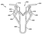
さらに別の例示的なファスナ400が、図12及び図13に示される。この実施形態において、前述した構造部の多くは類似している。ファスナ400は、本体402、中央キャビティ404、第1のばねアーム416、及び第2のばねアーム418を含む。この実施形態において、ファスナ400は、第3のばねアーム420及び第4のばねアーム422も含む。付加的なばねアームにより、ファスナ400をより広い範囲の材料厚に固定することが可能になるので、この実施形態における第3のばねアーム420及び第4のばねアーム422の付加により、ファスナ400がより幅広い部品と適合可能な付加的な可撓性を有することが可能になる。
Yet another
図12及び図13に示されるように、第1のばねアーム416及び第3のばねアーム420は、ファスナ400の第1の側406から後端部412に向けて外方に延びることができる。第2のばねアーム418及び第4のばねアーム422は、後端部412に向けて外方に同様に延びるが、第2の側408から延びることができる。第2のばねアーム418及び第4のばねアーム422は、外方に延びて、それぞれ第2の肩部426及び第4の肩部430において第2の側408に向けて折り返すことができる。第2の肩部426及び第4の肩部430は、第2の側408の後端部412においてフランジ434の下方に配置することができる。フランジ434と第2の肩部426及び第4の肩部430との間の垂直方向距離は、異なる。ファスナ400のこの構成により、このファスナ400を、異なる材料厚を有する複数の異なる第2の構成部品と共に使用することが可能になる。
As shown in FIGS. 12 and 13,
第1のばねアーム416及び第3のばねアーム420は、第1の側406上に配置される。第1のばねアーム416及び第3のばねアーム420は、第1の肩部424及び第3の肩部428を有した状態で前述されたのと同様に構成される。この構成において、第1のばねアーム416及び第3のばねアーム420は、第2のばねアーム418及び第4のばねアーム422と同じ種々の材料厚を適合することができる。
A
この実施形態において、第1のばねアーム416及び第2のばねアーム418は、図12に示されるように互いから横方向にオフセットして配置される。第3のばねアーム420及び第4のばねアーム422も、互いから横方向にオフセットされる。このように、補完的なばねアームにより与えられる保持力が、第2の構成部品にわたって横方向に分散され、ファスナ400の回転又はねじれを最小にする。
In this embodiment,
ここで図14~図17を参照すると、別の例示的なファスナ500が示される。例示的なファスナ500は、例示的なファスナ10、300、又は400の構造部の多くを含むことができる。理解されるように、該当する場合、例示的なファスナ500と共に用い得る前述の構造部及び機能は、ここで再度詳細に説明する必要はない。
Referring now to FIGS. 14-17, another
図示されるように、ファスナ500は、この例では、第1の側502、第2の側504、挿入端部506、及び終端部508を含む。例示的なファスナ500は、第1の側502が第2の側504の反対側に配置されたU形状である。第1の側502は、丸い挿入端部506によって第2の側504に接続して、中央本体キャビティ510を形成することができる。上述のように、中央本体キャビティ510は、第1の側502と第2の側504との間にリブ82を受けることができる。終端部508は、挿入端部506の反対側のファスナ500の端部に配置される。終端部508は、第1の側502上の第1のフランジ部分512と、第2の側504上の第2のフランジ部分514とを含むことができる。第1のフランジ部分512及び第2のフランジ部分514は、外方にかつ中央本体キャビティ510から離れるように角度を付けることができる。このように、第1のフランジ部分512及び第2のフランジ部分514は、リブ82を中央本体キャビティ510内に案内するのを助けることができる。
As shown,
例示的なファスナ500は、第1のバーブ延長部516、第2のバーブ延長部518、第3のバーブ延長部520、及び第4のバーブ延長部522を含むこともできる。前述のように、第1のバーブ延長部516、第2のバーブ延長部518、第3のバーブ延長部520、及び第4のバーブ延長部522は、ファスナ500の横方向側縁部に接続され、湾曲されるか、又は第1の側502と第2の側504との間の中央本体キャビティ510内に折り返される。第1のバーブ延長部516、第2のバーブ延長部518、第3のバーブ延長部520、及び/又は第4のバーブ延長部522の遠位端において、1つ又はそれ以上のバーブを接続することができる。バーブは、バーブがリブ82を把持してリブ82を中央本体キャビティ510内に保持できるように、内方にかつ中央本体キャビティ510の中心に向けて角度が付けられる。
The
図14~図17に示される例において、ファスナ500は、第1のバーブ延長部516、第2のバーブ延長部518、第3のバーブ延長部520及び第4のバーブ延長部522の各々に接続された一対のバーブ518を含む。図示されるように、ファスナは、第1のバーブ524、第2のバーブ526、第3のバーブ528、第4のバーブ530、第5のバーブ532、第6のバーブ534、第7のバーブ536、及び第8のバーブ538を含む。バーブは、中央本体キャビティ510内の異なる垂直方向高さに配置することができる。図示される例において、第1のバーブ524及び第5のバーブ532は、第1のバーブ延長部516に接続される。第1のバーブ524及び第2のバーブ526は、第1のバーブ延長部516から実質的に同じ角度に沿って角度が付けられるが、挿入端部506に対して異なる垂直方向高さで外方に湾曲し始める。従って、第1のバーブ524及び第2のバーブ526の端部は、中央本体キャビティ510内の異なる垂直方向高さで終端する。バーブ間のこのような変形により、リブ82がファスナ500内に挿入されるとき、バーブが、リブ82の異なる部分を保持することができる。
In the example shown in FIGS. 14-17,
図示される例において、第1のバーブ延長部516、第2のバーブ延長部518、第3のバーブ延長部520、及び第4のバーブ延長部522上の各対のバーブは、前述したものとは異なるプロファイルを有し得る。互いに真向いに配置されたバーブが、挿入端部506に対して異なる垂直方向高さに配置されるように、対向する対のバーブ(すなわち、第1及び第5のバーブ対第3及び第7のバーブ)を互い違いに配置することができる。他の例において、バーブは、ファスナ10、300、又は400に関して説明したもののような構成を有することができ、又は他の構成を有することができる。
In the illustrated example, each pair of barbs on
ファスナ500は、この例においては、4つのばねアームを含む。第1の側502は、第1のばねアーム540及び第2のばねアーム542を含むことができ、第2の側504は、第3のばねアーム544及び第4のばねアーム546を含むことができる。ファスナ500のばねアームは、例示的なファスナ400について前述したものと類似し得る。4つのばねアームの各々は、図示される例においては、外方にかつ中央本体キャビティ510から離れるように角度が付けられる。第1及び第2のばねアーム540、542は、外方にかつ第1の側502から離れるように延び、第3及び第4のばねアーム544、546は、外方にかつ第2の側504から離れるように延びる。
ファスナ400に関して前述したように、ファスナ500のばねアームは、終端部508に対して異なる垂直方向高さで中央キャビティに向けて折り返され得る。図示されるように、第1のばねアーム540は、第1の肩部578において中央本体キャビティ510に向けて折り返され、第2のばね542は、第2の肩部580において中央本体キャビティ510に向けて折り返され得る。第1の肩部578は、第2の肩部580よりも終端部508に対して異なる垂直方向高さで配置することができる。理解できるように(及び上述のように)、これにより、ファスナ500が、異なる材料厚を有するパネルを保持することが可能になる。例えば、第1の肩部578は、第2の肩部580よりも、終端部508からより大きい垂直方向距離に配置される。このタイプの構成において、第1のばねアーム540は、第2のばねアーム542より厚い厚さを有するパネルを保持することができる。
As previously discussed with respect to
前方から見たとき(図15に示されるように)、ファスナ500は、第1のスロット550、第2のスロット552、及び第3のスロット554を含むことができる。第1のスロット550は、第1の側502の側壁及び第1のばねアーム540の側方外縁部566により定められる。第2のスロット552は、第1のばねアーム540の側方内縁部568及び第2のばねアーム542の側方内縁部570により定められる。第3のスロット554は、第2のばねアーム542の側方外縁部572及び第1の側502の側壁により定められる。図示されるように、第1のスロット550、第2のスロット552、及び第3のスロット554は、実質的に同じ垂直方向高さ及び横方向幅を有し、互いに平行に配置され得る。理解できるように、第1のスロット550は、第1のばねアーム540が第1の側502に対して撓むことができるように、第1のばねアーム540を第1の側502から分離する。同様に、第3のスロット554は、第1の側502と独立して同様に撓むように、第2のばねアーム542を第1の側502から分離する。
When viewed from the front (as shown in FIG. 15),
第2のスロット552は、第1のばねアーム540と第2のばねアーム542との間に配置される。従って、第2のスロット552は、第1のばねアーム540が、第2のばねアーム542と独立して、第1の側502に対して撓むことを可能にする。
A
第1のばねアーム540及び第2のばねアーム542は、隙間558により互いから分離されるので、これらが互いから独立して撓むことが可能である。隙間558は、前述した第2のスロット552の一部分とすることができる。第1のばねアーム540及び第2のばねアーム542は、それぞれ第1の接続端部560及び第2の接続端部562において第1の側502に接続される。隙間558(又は第2のスロット552の下部)は、第1の接続端部560と第2の接続端部562との間に配置される。図14~図17に示されるように、例示的なファスナ500の隙間558は、第1の接続端部560及び第2の接続端部562に隣接して、及び/又はこれらと実質的に同じ垂直方向高さ(挿入端部506に対して)に配置することができる。
The
図15に示されるように、第1の接続端部560及び第2の接続端部562は、第1の側502の挿入端部506より上方に高さXで配置することができる。隙間558は、図示されるような同じ垂直方向高さXで配置することができる。以下にさらに説明されるように、本開示のファスナの他の例は、高さXを超えて又は第1及び第2の接続端部560、562を超えて延びる隙間558を含むことができる。
As shown in FIG. 15, the first connecting
さらに図示されるように、第1のばねアーム540は、第1の湾曲部574において第1の側502から離れるように湾曲し得る。同様に、第2のばねアーム542は、第2の湾曲部576において第1の側502から離れるように湾曲し得る。図15に示される例において、第1の湾曲部574及び第2の湾曲部576は、垂直方向に位置合わせされる。このように、第1の湾曲部574及び第2の湾曲部576は、曲げ線Bを定めることができる。図示されるように、隙間558は、曲げ線Bを超えて(すなわち、第1の湾曲部574及び第2の湾曲部576を超えて)挿入端部506に向けて延びる。以下にさらに説明されるように、隙間558は、曲げ線Bを超えて様々な度合で延びることができる。一例において、隙間558は、少なくとも1mm、曲げ線Bを超えて及び/又は第1の湾曲部574及び第2の湾曲部576を超えて延びることができる。別の例において、隙間558は、少なくとも3mm、第1の湾曲部574及び/又は第2の湾曲部576を超えて延びることができる。
As further illustrated,
上述のように、第1のばねアーム540は、第1の側502から離間配置された側方外縁部566を含む。同様に、第2のばねアーム542は、同じく第1の側502から離間配置された側方外縁部572も含む。第1のばねアーム540の側方内縁部568は、第2のばねアーム542の側方内縁部570から離間配置される。図15の例において、第1のばねアーム540の側方外縁部566の外部横方向高さH1は、第1のばねアーム540の側方内縁部568の内部横方向高さH2に等しい。第2のばねアーム542の側方外縁部572の外部横方向高さH1は、第2のばねアーム542の側方内縁部570の内部横方向高さH2に等しい。他の例示的なファスナ(以下に説明される)において、横方向内部高さH2は、外部横方向高さH1よりも長くすることができ、隙間558(及び/又は第2のスロット552)は、第1のばねアーム540及び/又は第2のばねアーム542の側方外縁部よりも挿入端部506に向けてさらに延びることができる。
As mentioned above,
さらに図示されるように、第1のスロット550は接続縁部584を有することができ、第3のスロット554は接続縁部586を有することができる。接続縁部584、586は、それぞれ第1の接続端部560及び第2の接続端部562に又はその付近に配置される。第1のばねアーム540の側方外縁部566は、接続縁部584において第1の側502に接続し、第2のばねアーム542の側方外縁部572は、接続縁部586において第1の側502に接続する。第1のばねアーム540の側方内縁部568及び第2のばねアーム542の側方内縁部570は、ベース縁部582において接続される。図示される例において、接続縁部584、586は、ベース縁部582と同じ垂直方向高さ(挿入端部506に対する)で配置される。他の例において、以下にさらに説明されるように、ベース縁部582は、接続縁部584、586よりも挿入端部506の近くに配置することができる。
As further illustrated, the first slot 550 can have a connecting
例示的なファスナ500は、架橋部分564も含むことができる。架橋部分564は、ファスナ500の横方向半分を互いに接続するファスナ500の一部分である。架橋部分564は、ファスナ500の横方向半分(第1のばねアーム540及び第3のばねアーム544を含む半分)を、ファスナの反対側の横方向半分(第2のばねアーム542及び第4のばねアーム546を含む反対側の半分)に接続する隙間558に隣接して(又はその中に)配置される挿入端部506における材料である。架橋部分564は、第1の側502の隙間558から第2の側504の隙間558まで挿入端部506の周りで周方向に測定される周方向長さL(例えば図22参照)を有することができる。種々の例において、架橋部分564は、様々なサイズの長さを有することができる。
理解されるように、ファスナ500は、第2の側504上の前述したものと実質的に同じ構造体及び構成を含むことができる。第3のばねアーム544及び第4のばねアーム546を同様に分離することができ、第2の側504に対して独立して撓むことを可能にする。第3のばねアーム544及び第4のばねアーム546は、隙間558により分離することもできる。こうした例において、隙間が互いに向けて挿入端部506の周りに延びるように、第2の側504上の隙間558を、第1の側502上の隙間558と横方向に位置合わせすることができる。他の例において、隙間558は、他のサイズを有することができ、又は第1及び第2のばねアーム540、542及び/又は第3及び第4のばねアーム544、546に対して他の位置を有することができる。
As will be appreciated,
ここで図18及び図19を参照すると、例示的なファスナ600が、挿入端部604を通って延びる隙間602を含む。例示的なファスナ600は、既述のものと実質的に類似した4つのばねアーム構成を含む。しかしながら、この例において、第1のばねアーム606及び第2のばねアーム608は、挿入端部604において互いに接続されていない。隙間602は、第1のばねアーム606の第1の接続端部610を超えて(及び下方に)かつ第2のばねアーム608の第2の接続端部612を超えて(及び下方に)延びる。この例において、第1のばねアーム606及び第2のばねアーム608は、後端部614において互いに間接的に接続されるにすぎない。同様に、第3のばねアーム616及び第4のばねアーム618は、挿入端部604において互いに接続されていず、後端部614において互いに間接的に接続されるにすぎない。この例において、例示的なファスナ600の架橋部分の長さはゼロである。
Referring now to FIGS. 18 and 19, an
図19に示されるように、第1の接続端部610及び第2の接続端部612は、挿入端部604の上に配置された垂直方向高さXを定める。この例において、隙間602は、垂直方向高さXを超えて延びることができる。さらに図示されるように、第1のばねアーム606は、第1の湾曲部624において第1の側622から外方に湾曲し、第2のばねアーム608は、第2の湾曲部626において第1の側622から外方に湾曲する。第1の湾曲部624及び第2の湾曲部626は、この例では垂直方向に位置合わせされ、曲げ線Bを定めることができる。隙間602は、第1の湾曲部624及び/又は第2の湾曲部626を超えて(又は曲げ線Bを超えて)挿入端部604に向けて延びることができる。
As shown in FIG. 19, first connecting
第1のばねアーム606は、側方外縁部628及び側方内縁部630をさらに含むことができる。第2のばねアーム608は、側方内縁部632及び側方外縁部634を含むことができる。図示されるように、第1のばねアーム606の側方外縁部628及び/又は第2のばねアーム608の側方外縁部634は、挿入端部604に対して垂直方向高さH1を有することができる。第1のばねアーム606の側方内縁部630及び第2のばねアーム608の側方内縁部632は、挿入端部604に対して垂直方向高さH2を有することができる。図示されるように、垂直方向高さH2は、垂直方向高さH1より長い。
ここで図20及び図21を参照すると、さらに別の例示的なファスナ700が示される。この例において、ファスナ700は、第1のばねアーム706の第1の接続端部704を超えて(又は下方に)、かつ第2のばねアーム710の第2の接続端部708を超えて(又は下方に)延びる隙間702を有する。図21に見られるように、隙間702は、第1のばねアーム706及び第2のばねアーム710の側方外側にスロットが配置された挿入端部712に向けてさらに延びる。第1の接続端部704及び第2の接続端部708は、挿入端部712の上方に配置された垂直方向高さXを定めることができる。隙間702は、挿入端部712に近接した隙間702の縁部が、図示のようにG1の垂直方向高さに配置されるように、挿入端部712に向けて延びる。この例において、垂直方向高さG1(隙間702のベース縁部734が垂直方向に配置される)は、隙間702が第1の接続端部704及び第2の接続端部708を超えて延びるように、垂直方向高さXを下回る。幾つかの例において、隙間702は、1mmより多く、第1の接続端部704及び/又は第2の接続端部708を超えて延びることができる。他の例において、隙間702は、2mm又はそれより多く、第1の接続端部704及び/又は第2の接続端部708を超えて延びることができる。
Referring now to FIGS. 20 and 21, yet another
この例においてさらに示されるように、第1のばねアーム706は、第1の湾曲部720において第1の側718から外方に湾曲し、第2のばねアーム710は、第2の湾曲部722において第1の側718から外方に湾曲する。第1の湾曲部720及び第2の湾曲部722は、この例においては垂直方向に位置合わせされ、曲げ線Bを定めることができる。隙間702は、第1の湾曲部720及び/又は第2の湾曲部722を超えて(又は曲げ線Bを超えて)挿入端部712に向けて延びることができる。隙間702のベース縁部734は、曲げ線Bの下方に垂直方向距離G2で配置される。見られるように、垂直方向距離G2は、隙間702が接続縁部732、736を超えて延びるように、垂直方向距離G1より大きい。
As further shown in this example, the
第1のばねアーム706は、側方外縁部724及び側方内縁部726をさらに含むことができる。第2のばねアーム710は、側方内縁部728及び側方外縁部730を含むことができる。図示されるように、第1のばねアーム706の側方外縁部724及び/又は第2のばねアーム710の側方外縁部730は、挿入端部712に対して垂直方向高さH1を有することができる。第1のばねアーム706の側方内縁部726及び第2のばねアーム710の側方内縁部728は、挿入端部712に対して垂直方向高さH2を有することができる。図示されるように、垂直方向高さH2は、垂直方向高さH1より長い。
理解されるように、隙間702は、曲げ線Bを超えて及び/又は接続縁部732、736を超えて、種々の距離を延びることができる。例えば、垂直方向距離G2は、1mm、2mm、又は2mmより多くすることができる。隙間702は、第1のばねアーム706が、第2のばねアーム710から独立して、ファスナ700の本体から内方及び外方に撓むように、挿入端部712に向けて延びることができる。このように、ファスナ700は、種々の厚さのパネルにしっかりと繰り返し固定される。図21に示されるように、第1のばねアーム706(及び第2のばねアーム710)は、横方向幅Wを有することができる。隙間702は、第1の湾曲部720及び/又は第2の湾曲部722を超えて挿入端部712に向けて、第1のばねアーム706の横方向幅Wの少なくとも3分の1である垂直方向距離だけ延びることができる。別の例において、隙間702は、第1の湾曲部720及び/又は第2の湾曲部722を超えて挿入端部712に向けて、第1のばねアーム706の横方向幅Wの少なくとも半分である垂直方向距離だけ延びることができる。こうした例において、垂直方向距離G2は、横方向幅Wの3分の1又は横方向幅Wの2分の1であり得る。他の例において、隙間702は、曲げ線Bから種々の距離を延びる(又は挿入端部712の周りに完全に延びる)ことができる。
As will be appreciated, the
図22及び図23に示されるようなさらに別の例において、ファスナ800は、挿入端部814内に延びる隙間802を含むことができる。この例において、隙間802は、挿入端部814の湾曲部分の周りに延びる。隙間802は、第1のばねアーム806の第1の接続端部804を超えて(又は下方に)及び第2のばねアーム810の第2の接続端部808を超えて(又は下方に)延びる。例示的なファスナ800は、前述したもののような関係及び相対的サイズを有することができる。第1のばねアーム806及び第2のばねアーム810の側方外縁部818、824は、第1のばねアーム806及び第2のばねアーム810の側方内縁部820、822の垂直方向高さH2よりも短い垂直方向高さH1を有し得る。
In yet another example, as shown in FIGS. 22 and 23,
図示され、前述したように、本開示のファスナは、様々な長さの架橋部分を有し得る。図22に示されるように、ファスナ800は、丸い挿入端部814の頂点にのみ配置される架橋部分812を有し得る。幾つかの例において、架橋部分812は、1mm又はそれより少ない長さLを有し得る。他の例では、架橋部分は、3mm又はそれより少ない長さLを有し得る。図20に示されるように、例示的なファスナ700は、ファスナ800の架橋部分812よりも長い架橋部分を有し得る。例示的なファスナ700は、3mm又はそれより多い長さを有する架橋部分714を有し得る。図18に示されるように、架橋部分は、0mmの長さを有し得る。こうした構成において、ファスナ600のように、第1のばねアーム及び第2のばねアームが、挿入端部において互いから完全に分離される(又は離れている)。
As illustrated and discussed above, the fasteners of the present disclosure can have bridging portions of varying lengths. As shown in FIG. 22, the
ここで図24~図26を参照すると、別の例示的なファスナ900が示される。例示的なファスナ900は、第1のばねアーム906及び第2のばねアーム910に隣接して下方に延びる隙間902を含む。例示的なファスナ900は、前述したものに実質的に類似した4つのばねアーム及び構成を含む。例示的なファスナ900は、この例におけるバーブが折り曲げられたバーブ延長部によりファスナ900に接続されていない点を除いて、例示的なファスナ700に実質的に類似している。さらに、第1の側922及び第2の側924は、前述のように互いに対して実質的に平行ではなく、互いに対して鋭角をなして配向される。理解されるように、第1の側922及び第2の側924は、この例においても互いに実質的に平行に配向され得る。
Referring now to FIGS. 24-26, another
例示的なファスナ900において、第1のバーブ940、第2のバーブ942、第3のバーブ944、第4のバーブ946、第5のバーブ948、第6のバーブ950、第7のバーブ952、及び第8のバーブ954が、第1の側922又は第2の側924に直接接続される。第1のバーブ940、第2のバーブ942、第3のバーブ944、及び第4のバーブ946は、第1の側922から挿入端部912に向けて内方に突出し得る。第5のバーブ948、第6のバーブ950、第7のバーブ952、及び第8のバーブ954は、第2の側924から挿入端部912に向けて内方に突出し得る。バーブは、第1の側922又は第2の側924に沿っていずれかの適切な高さで配置することができる。図示される例において、第1のバーブ940及び第2のバーブ942は、ファスナ900上で垂直方向及び横方向に互い違いに配置される。同様に、第3のバーブ944は、第4のバーブ946から垂直方向及び横方向に互い違いに配置される。第5のバーブ948は、第6のバーブ950から垂直方向及び横方向に互い違いに配置され、第7のバーブ952は、第8のバーブ954から垂直方向及び横方向に互い違いに配置される。他の例においては、バーブは、異なる相対的位置を有することができ、又は異なる配向でファスナ900上に設けることができる。
In the
ファスナ700に関して前述したように、この例示的なファスナ900は、隙間902によって互いから分離される第1のばねアーム906及び第2のばねアーム910を含む。この例において、隙間902は、第1のばねアーム906及び第2のばねアーム910の横方向外側に配置されたスロットよりも挿入端部912に向けてさらに延びる。
As previously discussed with respect to
隙間902は、挿入端部912に近接する隙間902のベース縁部が、図示されるようなG1の垂直方向高さで配置されるように、挿入端部912に向けて延びる。この例において、隙間902は、第1の接続端部904及び第2の接続端部908を超えて延びる。幾つかの例において、隙間902は、1mmより多く、第1の接続端部904及び/又は第2の接続端部908を超えて延びることができる。他の例において、隙間902は、2mm又はそれより多く、第1の接続端部904及び/又は第2の接続端部908を超えて延びることができる。さらに他の例において、ファスナ900(図示のようなバーブを有する)は、隙間902の前述の構成のいずれかを含むこともできる。
ここで図27を参照すると、例示的なブランク970が示される。ブランク970は、ばね鋼、又は図示されるようなプロファイルを有するように形成された他の適切な材料の平坦な部分である。ブランク970は、打抜き加工、レーザ切断等のような適切なプロセスで形成することができる。その後、ブランク970は、前の例に示されるようなU形状を有するように形成することができる。 Referring now to FIG. 27, an exemplary blank 970 is shown. Blank 970 is a flat section of spring steel or other suitable material formed with a profile as shown. Blank 970 may be formed by any suitable process, such as stamping, laser cutting, or the like. The blank 970 can then be formed to have a U-shape as shown in the previous example.
図示される例において、ブランク970は、第1のバーブ940、第2のバーブ942、第3のバーブ944、第4のバーブ946、第5のバーブ948、第6のバーブ950、第7のバーブ952、及び第8のバーブ954を含む。さらに、ブランク970は、第1のばねアーム906、第2のばねアーム910、第3のばねアーム914、及び第4のばねアーム916を含む。理解されるように、ブランク970は、前述したファスナ900に実質的に類似したファスナを形成することができる。
In the illustrated example, blank 970 includes
しかしながら、この例において、隙間972は、図24~図26に示されるような隙間902とは異なる。隙間972は、第1のばねアーム906を第2のばねアーム910から完全に分離する連続スロットである。この点で、隙間972は、例示的なファスナ600(図18及び図19)において前述されたれた隙間602に類似している。
However, in this example,
図示されるように、ブランク970は、第1のタブ974及び第2のタブ976を含むことができる。第1のタブ974及び第2のタブ976は、この例では、隙間972内に横方向に突出する材料の突出部である。第1のタブ974は、挿入端部912に向けて第1の側922上に配置され、第2のタブ976は、挿入端部912に向けて第2の側924上に配置される。第1のタブ974及び第2のタブ976は、隙間972にわたって横方向に及ぶが、隙間972の対向する側縁部に接続されない。第1のタブ974及び第2のタブ976は、隙間972の対向する側縁部に接触し得るが、隙間972は、第1のばねアーム906及び第2のばねアーム910が互いに対して独立に撓むことができるように、第1のタブ974及び第2のタブ976に接触しないままである。
As shown, blank 970 can include a
ブランク970内に第1のタブ974及び第2のタブ976を含ませて、ファスナが第2の構成部品84(図1)に挿入されたとき、ファスナが互いに横方向に締め付けられる又は押し潰されるのを防止することができる。理解されるように、隙間972が第1のタブ974及び/又は第2のタブ976を含まないファスナにおいて、ブランク970から形成されたファスナの横方向半分が、挿入端部912において互いに向けて横方向に締め付けされる又は押し潰されることがある。第1のタブ974及び/又は第2のタブ976を有する例においては、こうした締め付け又は押し潰しを防止すること又は最小化することができる。
Include
上記の例において、第1のばねアーム及び第2のばねアームは、接続すること、又は様々な程度に互いから完全に分離することが可能である。第1のばねアームを第2のばねアームから分離する隙間のサイズ及び位置により、第1のばねアーム及び第2のばねアームは、互いに独立して撓むための異なる能力を有し得る。有利なことに、このことは、ファスナが、種々の厚さのパネルを繰り返しかつしっかりと把持及び保持することを可能にする。 In the above examples, the first spring arm and the second spring arm can be connected or completely separated from each other to varying degrees. Depending on the size and location of the gap separating the first spring arm from the second spring arm, the first spring arm and the second spring arm may have different abilities to deflect independently of each other. Advantageously, this allows the fastener to repeatedly and securely grip and hold panels of various thicknesses.
ファスナ10、300、400、500、600、700、800及び900を含む本開示のファスナは、ファスナの種々の要素が、撓み、湾曲し、又は弾性変形して、前述したような機能を与えることができるように、適切な材料で作成される。状況によっては、適切なばね鋼からファスナを作成することによって、ファスナの弾性性質が生成される。しかしながら、他の状況においては、本開示のファスナは、他の金属、合金、プラスチック、又は複合材料で作成することができる。
The fasteners of the present disclosure, including
当業者には、具体的な詳細を用いる必要がないこと、例示的な実施形態は多くの異なる形態で具体化できること、及び、いずれも本開示の範囲を限定するものと解釈すべきではないことが明らかであろう。幾つかの例示的な実施形態において、周知のプロセス、周知の装置構造、及び周知の技術は、詳細に説明していない。 Those skilled in the art will appreciate that specific details need not be used, that the exemplary embodiments can be embodied in many different forms, and that nothing should be construed as limiting the scope of the disclosure. should be obvious. In some example embodiments, well-known processes, well-known device structures, and well-known techniques are not described in detail.
第1、第2、第3等の用語は、本明細書において種々の要素、構成部品、領域、層、及び/又はセクションを説明するために用いられていることがあるが、これらの要素、構成部品、領域、層、及び/又はセクションは、これらの用語によって制限されるべきではない。これらの用語は単に、1つの要素、構成部品、領域、層、又はセクションと、別の領域、層、又はセクションとを区別するために用いることができる。「第1」、「第2」及びその他の数の用語のような用語は、本明細書において用いられるとき、文脈により明らかに示されていない限り、シーケンス又は順序を意味するものではない。従って、以下で論じる第1の要素、構成部品、領域、層又はセクションは、例示的な実施形態の教示から逸脱することなく、第2の要素、構成部品、領域、層又はセクション損と名付けることができる。 Terms such as first, second, third, etc. may be used herein to describe various elements, components, regions, layers, and/or sections; The components, regions, layers, and/or sections should not be limited by these terms. These terms may only be used to distinguish one element, component, region, layer, or section from another region, layer, or section. Terms such as "first," "second," and other numerical terms, when used herein, do not imply a sequence or order unless the context clearly dictates otherwise. Accordingly, a first element, component, region, layer or section discussed below may be termed a second element, component, region, layer or section without departing from the teachings of the exemplary embodiments. I can do it.
例示的な実施形態及び例示的な用途の上記の説明は、図示及び説明のために与えられている。これは、網羅的であること又は本開示を限定することを意図するものではない。具体的に示され又は説明されていない場合でも、特定の実施形態の個々の要素又は特徴は、一般に、その特定の実施形態に限定されるものではなく、適用可能な場合には、交換可能であり、選択された実施形態において用いることができる。特定の実施形態の個々の要素又は特徴は、多くの方法で変化し得る。こうした変形は、本開示からの逸脱とみなすべきではなく、全てのこうした変更は、本開示の範囲内に含まれることが意図される。 The above descriptions of example embodiments and example applications have been presented for purposes of illustration and description. It is not intended to be exhaustive or limit the disclosure. Even if not specifically shown or described, individual elements or features of a particular embodiment are generally not limited to that particular embodiment and, where applicable, may be interchangeable. Yes, and can be used in selected embodiments. Individual elements or features of a particular embodiment may vary in many ways. Such variations are not to be considered a departure from this disclosure, and all such modifications are intended to be included within the scope of this disclosure.
10、300、400、500、600、700、800、び900:ファスナ
12、302、402:本体
14、304、404、510:中央本体キャビティ
16、306、406、502、622、718、922:第1の側
18、308、408、504、924:第2の側
20、310、506、604、712、814、912:挿入端部
22、312、412、614:後端部
24、314:側方側縁部
26、332、512:第1のフランジ
28、334、514:第2のフランジ
34、316、416、540、606、706、806、906:第1のばねアーム
36、318、418、542、608、710、810、910:第2のばねアーム
40、324:第1の肩部
44、426:第2の肩部
46:終端部
50、350、516:第1のバーブ延長部
52、352、524、904:第1のバーブ
54、354、520:第3のバーブ延長部
56、356、528、944:第3のバーブ
58、358、518:第2のバーブ延長部
60、360、526、942:第2のバーブ
62、362、522:第4のバーブ延長部
64、364、530、946:第4のバーブ
66、574、626、720:第1の湾曲部
68、368:遠位端
72、158、160:尖端部
76:側方外縁部
78:側方内縁部
80:第1の構成部品
82:リブ
84:第2の構成部品
86:開口部
256:バーブ
260:平坦なセクション
420、544、914:第3のばねアーム
422、546、916:第4のばねアーム
426:第3の肩部
430:第4の肩部
532、948:第5のバーブ
534、950:第6のバーブ
536、952:第7のバーブ
538、954:第8のバーブ
558、602、702、802、902:隙間
560、610、704、804、904:第1の接続端部
562、612、708、810、908:第2の接続端部
576、626、722:第2の湾曲部
734:ベース縁部
970:ブランク
B:曲げ線
10, 300, 400, 500, 600, 700, 800, and 900: Fasteners 12, 302, 402: Body 14, 304, 404, 510: Central body cavity 16, 306, 406, 502, 622, 718, 922: First side 18, 308, 408, 504, 924: Second side 20, 310, 506, 604, 712, 814, 912: Insertion end 22, 312, 412, 614: Back end 24, 314: Lateral side edges 26, 332, 512: first flange 28, 334, 514: second flange 34, 316, 416, 540, 606, 706, 806, 906: first spring arm 36, 318; 418, 542, 608, 710, 810, 910: second spring arm 40, 324: first shoulder 44, 426: second shoulder 46: termination 50, 350, 516: first barb extension Sections 52, 352, 524, 904: First barb 54, 354, 520: Third barb extension 56, 356, 528, 944: Third barb 58, 358, 518: Second barb extension 60 , 360, 526, 942: second barb 62, 362, 522: fourth barb extension 64, 364, 530, 946: fourth barb 66, 574, 626, 720: first curved section 68, 368: Distal end 72, 158, 160: Point 76: Lateral outer edge 78: Lateral inner edge 80: First component 82: Rib 84: Second component 86: Opening 256: Barb 260 : flat section 420, 544, 914: third spring arm 422, 546, 916: fourth spring arm 426: third shoulder 430: fourth shoulder 532, 948: fifth barb 534; 950: Sixth barb 536, 952: Seventh barb 538, 954: Eighth barb 558, 602, 702, 802, 902: Gap 560, 610, 704, 804, 904: First connection end 562 , 612, 708, 810, 908: second connecting end 576, 626, 722: second curved section 734: base edge 970: blank B: bending line
Claims (20)
第1の側と第2の側との間に中央リブ受けキャビティを定め、前記第1の側は挿入端部において前記第2の側に接続され、前記中央リブ受けキャビティは前記リブを受けるように設計される、U形状本体と、
前記本体の前記第1の側に接続され、前記中央リブ受けキャビティ内に内方にかつ前記挿入端部に向かって湾曲し、前記リブを前記中央リブ受けキャビティ内に保持するように配置されかつ設計された第1のリブ保持バーブと、
前記本体の前記第1の側に接続され、第1の湾曲部において前記中央リブ受けキャビティから外方に離れかつ前記挿入端部から離れるように湾曲し、前記アパーチャの周縁部に係合して前記弾性Uベース型ファスナを前記アパーチャ内に保持するように配置されかつ設計された第1のアパーチャ保持ばねアームと、
前記第1のアパーチャ保持ばねアームに隣接して前記本体の前記第1の側に接続され、第2の湾曲部において前記中央リブ受けキャビティから外方に離れかつ前記挿入端部から離れるように湾曲し、前記アパーチャの前記周縁部に係合して前記弾性Uベース型ファスナを前記アパーチャ内に保持するように配置されかつ設計された第2のアパーチャ保持ばねアームと、
を含み、
前記第1のアパーチャ保持ばねアーム及び前記第2のアパーチャ保持ばねアームは、互いから横方向に離間配置され、前記本体の前記第1の側において隙間により互いから分離され、前記第1及び第2のアパーチャ保持ばねアームの側方内縁部は、前記側方内縁部との前記隙間の両側をそれぞれ定め、前記本体の前記第1の側における前記隙間は、前記第1及び第2のアパーチャ保持ばねアームのそれぞれの自由遠位端から前記第1の湾曲部を超えて及び前記第2の湾曲部を超えて前記挿入端部に向かって連続して延びており、前記隙間は、前記第1の湾曲部を超えて少なくとも1mm延びることを特徴とする、弾性Uベース型ファスナ。 A resilient U-based fastener coupling a first component having a rib to a second component having an aperture therethrough, the fastener comprising:
a central rib-receiving cavity is defined between a first side and a second side, the first side connected to the second side at an insertion end, and the central rib-receiving cavity configured to receive the rib. A U-shaped main body designed to
connected to the first side of the body and curved inwardly into the central rib receiving cavity and toward the insertion end and arranged to retain the rib within the central rib receiving cavity; a designed first rib retention barb;
connected to the first side of the body, curved at a first curved portion outwardly away from the central rib receiving cavity and away from the insertion end, and engaged with a peripheral edge of the aperture; a first aperture retention spring arm arranged and designed to retain the resilient U-based fastener within the aperture;
connected to the first side of the body adjacent to the first aperture retaining spring arm and curved outwardly away from the central rib receiving cavity and away from the insertion end at a second curved section; a second aperture retention spring arm positioned and designed to engage the peripheral edge of the aperture to retain the resilient U-based fastener within the aperture;
including;
The first aperture retention spring arm and the second aperture retention spring arm are laterally spaced apart from each other and separated from each other by a gap on the first side of the body, and the first and second aperture retention spring arms are lateral inner edges of the aperture retaining spring arms of the body define opposite sides of the gap with the lateral inner edges, and the gap on the first side of the body is defined by the first and second aperture retaining spring arms. extending continuously from the respective free distal ends of the arms past the first curved section and beyond the second curved section towards the insertion end, the gap being An elastic U-based fastener, characterized in that it extends at least 1 mm beyond the curve.
前記第2のアパーチャ保持ばねアームは、前記第2のアパーチャ保持ばねアームが前記中央リブ受けキャビティに向けて折り返す第2の肩部を含み、
前記第1のアパーチャ保持ばねアームの前記第1の肩部は、前記挿入端部とは反対に配置された前記ファスナの後端部に対して第1の垂直方向高さで配置されるとともに、前記第1の垂直方向高さに関連する第1の厚さを有する前記第2の構成部品において前記アパーチャの前記周縁部に係合して保持するように配置されかつ設計され、前記第2のアパーチャ保持ばねアームの前記第2の肩部は、前記ファスナの後端部に対して前記第1の垂直方向高さとは異なる第2の垂直方向高さで配置されるとともに、前記第2の垂直方向高さに関連する第2の厚さを有する前記第2の構成部品内の前記アパーチャの前記周縁部に係合して保持するように配置されかつ設計されることを特徴とする、請求項1に記載の弾性Uベース型ファスナ。 the first aperture retention spring arm includes a first shoulder where the first aperture retention spring arm folds back toward the central rib receiving cavity;
the second aperture retention spring arm includes a second shoulder where the second aperture retention spring arm folds back toward the central rib receiving cavity;
the first shoulder of the first aperture retention spring arm is disposed at a first vertical height relative to a rear end of the fastener disposed opposite the insertion end; arranged and designed to engage and retain the peripheral edge of the aperture in the second component having a first thickness associated with the first vertical height; the second shoulder of the aperture retaining spring arm is disposed at a second vertical height relative to the rear end of the fastener that is different than the first vertical height; Claim 1, characterized in that the second component is arranged and designed to engage and retain the peripheral edge of the aperture in the second component having a second thickness related to a directional height. 1. The elastic U-based fastener according to item 1.
第1の側と第2の側との間に中央リブ受けキャビティを定め、前記第1の側は挿入端部において前記第2の側に接続され、前記中央リブ受けキャビティは前記リブを受けるように設計される、U形状本体と、
前記本体の前記第1の側に接続され、前記中央リブ受けキャビティ内に内方にかつ前記挿入端部に向かって湾曲し、前記リブを前記中央リブ受けキャビティ内に保持するように配置されかつ設計された第1のリブ保持バーブと、
前記本体の前記第1の側に接続され、前記中央リブ受けキャビティから外方に離れかつ前記挿入端部から離れるように湾曲し、前記アパーチャの周縁部に係合して前記弾性Uベース型ファスナを前記アパーチャ内に保持するように配置されかつ設計された第1のアパーチャ保持ばねアームと、
前記第1のアパーチャ保持ばねアームに隣接して前記本体の前記第1の側に接続され、前記中央リブ受けキャビティから外方に離れかつ前記挿入端部から離れるように湾曲し、前記アパーチャの前記周縁部に係合して前記弾性Uベース型ファスナを前記アパーチャ内に保持するように配置されかつ設計された第2のアパーチャ保持ばねアームと、
を含み、
前記第1のアパーチャ保持ばねアームの側方内縁部及び前記第2のアパーチャ保持ばねアームの側方内縁部は、前記第1及び第2のアパーチャ保持ばねアームのそれぞれの自由遠位端から前記挿入端部に向かって連続して延びて前記第1のアパーチャ保持ばねアームを前記第2のアパーチャ保持ばねアームから互いから分離する、前記第1の側における隙間の両側を定め、前記第1のアパーチャ保持ばねアームの前記側方内縁部は、前記第1のアパーチャ保持ばねアームの側方外縁部の外部垂直方向高さより長い内部垂直方向高さを有することを特徴とする、弾性Uベース型ファスナ。 A resilient U-based fastener coupling a first component having a rib to a second component having an aperture therethrough, the fastener comprising:
a central rib-receiving cavity is defined between a first side and a second side, the first side connected to the second side at an insertion end, and the central rib-receiving cavity configured to receive the rib. A U-shaped main body designed to
connected to the first side of the body and curved inwardly into the central rib receiving cavity and toward the insertion end and arranged to retain the rib within the central rib receiving cavity; a designed first rib retention barb;
a resilient U-based fastener connected to the first side of the body and curved outwardly away from the central rib receiving cavity and away from the insertion end and engaged with a peripheral edge of the aperture; a first aperture retaining spring arm arranged and designed to retain within the aperture;
connected to the first side of the body adjacent to the first aperture retaining spring arm and curved outwardly away from the central rib receiving cavity and away from the insertion end; a second aperture retention spring arm arranged and designed to engage a peripheral edge to retain the resilient U-based fastener within the aperture;
including;
A lateral inner edge of the first aperture retaining spring arm and a lateral inner edge of the second aperture retaining spring arm extend from the free distal ends of each of the first and second aperture retaining spring arms. defining a gap on the first side extending continuously toward an end and separating the first aperture retaining spring arm from the second aperture retaining spring arm from each other; A resilient U-based fastener, wherein the inner lateral edge of the retaining spring arm has an inner vertical height that is greater than the outer vertical height of the outer lateral edge of the first aperture retaining spring arm.
前記第1の側の第2の側方縁部から横方向外方に延び、第2のリブ保持バーブを前記中央リブ受けキャビティ内に支持するように湾曲する第2のバーブと、
を含み、前記第2のリブ保持バーブは内方にかつ前記挿入端部に向けて延び、前記第2のリブ保持バーブは前記リブを前記中央リブ受けキャビティ内に保持するように配置されかつ設計されることを特徴とする、請求項5に記載の弾性Uベース型ファスナ。 a first barb extending laterally outwardly from a first lateral edge of the first side and curved to support the first rib retaining barb within the central rib receiving cavity;
a second barb extending laterally outwardly from a second lateral edge of the first side and curved to support a second rib retaining barb within the central rib receiving cavity;
said second rib retention barb extending inwardly and toward said insertion end, said second rib retention barb being positioned and designed to retain said rib within said central rib receiving cavity. The elastic U-based fastener according to claim 5, characterized in that:
前記第3のアパーチャ保持ばねアームに隣接して前記本体の前記第2の側に接続され、前記中央リブ受けキャビティから離れるように外方に湾曲する、第4のアパーチャ保持ばねアームと、
を含み、
前記第3のアパーチャ保持ばねアームの側方内縁部及び前記第4のアパーチャ保持ばねアームの側方内縁部は、前記第3のアパーチャ保持ばねアームを前記第4のアパーチャ保持ばねアームから分離するための第2の隙間を定め、前記第3のアパーチャ保持ばねアームの前記側方内縁部は、前記第3のアパーチャ保持ばねアームの側方外縁部の外部垂直方向高さよりも長い内部垂直方向高さを有することを特徴とする、請求項5に記載の弾性Uベース型ファスナ。 a third aperture retaining spring arm connected to the second side of the body and curving outwardly away from the central rib receiving cavity;
a fourth aperture retaining spring arm connected to the second side of the body adjacent to the third aperture retaining spring arm and curving outwardly away from the central rib receiving cavity;
including;
a lateral inner edge of the third aperture retaining spring arm and a lateral inner edge of the fourth aperture retaining spring arm to separate the third aperture retaining spring arm from the fourth aperture retaining spring arm; defining a second gap, wherein the lateral inner edge of the third aperture retaining spring arm has an inner vertical height that is greater than the outer vertical height of the lateral outer edge of the third aperture retaining spring arm. An elastic U-based fastener according to claim 5, characterized in that it has:
第1の側と第2の側との間に中央リブ受けキャビティを定め、前記第1の側は挿入端部において前記第2の側に接続される、U形状本体を含み、
前記本体の前記第1の側は、それぞれが前記中央リブ受けキャビティから離れるように外方に湾曲する第1のアパーチャ保持ばねアーム及び第2のアパーチャ保持ばねアームを含み、前記第1及び第2のアパーチャ保持ばねアームは、前記アパーチャの周縁部に係合して前記弾性Uベース型ファスナを前記アパーチャ内に保持するように配置されかつ設計され、
前記本体の前記第1の側は、それぞれが前記中央リブ受けキャビティ内に内方にかつ前記挿入端部に向かって湾曲する第1のリブ保持バーブ及び第2のリブ保持バーブを含み、前記第1及び第2のリブ保持バーブは、前記リブを前記中央リブ受けキャビティ内に保持するように配置されかつ設計され、
前記本体の前記第2の側は、それぞれが前記中央リブ受けキャビティから離れるように外方に湾曲する第3のアパーチャ保持ばねアーム及び第4のアパーチャ保持ばねアームを含み、前記第3及び第4のアパーチャ保持ばねアームは、前記アパーチャの前記周縁部に係合して前記弾性Uベース型ファスナを前記アパーチャ内に保持するように配置されかつ設計され、
前記第1のアパーチャ保持ばねアームの側方内縁部及び前記第2のアパーチャ保持ばねアームの側方内縁部は、前記第1及び第2のアパーチャ保持ばねアームのそれぞれの自由遠位端から前記挿入端部に向かって連続して延びて前記第1のアパーチャ保持ばねアームを前記第2のアパーチャ保持ばねアームから分離する、前記第1の側における第1の隙間の両側を定め、前記第3のアパーチャ保持ばねアームの側方内縁部及び前記第4のアパーチャ保持ばねアームの側方内縁部は、前記第3及び第4のアパーチャ保持ばねアームのそれぞれの自由遠位端から前記挿入端部に向かって連続して延びて前記第3のアパーチャ保持ばねアームを前記第4のアパーチャ保持ばねアームから分離する第2の隙間の両側を定めることを特徴とする、弾性Uベース型ファスナ。 A resilient U-based fastener coupling a first component having a rib to a second component having an aperture therethrough, the fastener comprising:
defining a central rib receiving cavity between a first side and a second side, the first side including a U-shaped body connected to the second side at an insertion end;
The first side of the body includes a first aperture retention spring arm and a second aperture retention spring arm, each of which curves outwardly away from the central rib receiving cavity; an aperture retaining spring arm arranged and designed to engage a peripheral edge of the aperture to retain the resilient U-based fastener within the aperture;
The first side of the body includes a first rib retention barb and a second rib retention barb each curved inwardly into the central rib receiving cavity and toward the insertion end; first and second rib retention barbs are arranged and designed to retain the rib within the central rib receiving cavity;
The second side of the body includes a third aperture retention spring arm and a fourth aperture retention spring arm, each of which curves outwardly away from the central rib receiving cavity; an aperture retention spring arm arranged and designed to engage the peripheral edge of the aperture to retain the resilient U-based fastener within the aperture;
A lateral inner edge of the first aperture retaining spring arm and a lateral inner edge of the second aperture retaining spring arm extend from the free distal ends of each of the first and second aperture retaining spring arms. defining a first gap on the first side extending continuously toward an end and separating the first aperture retaining spring arm from the second aperture retaining spring arm; A lateral inner edge of the aperture retaining spring arm and a lateral inner edge of the fourth aperture retaining spring arm extend from respective free distal ends of the third and fourth aperture retaining spring arms toward the insertion end. a resilient U-based fastener characterized in that the second aperture retaining spring arm extends continuously from the first aperture retaining spring arm to define opposite sides of a second gap separating the third aperture retaining spring arm from the fourth aperture retaining spring arm;
前記第2の側は、第3のバーブ延長部及び第4のバーブ延長部を含み、前記第3及び第4のバーブ延長部は、前記第2の側の両側面から横方向外方に延びて、前記第3及び第4のリブ保持バーブをそれぞれ前記中央リブ受けキャビティ内に支持するように横方向内方に湾曲され、前記第3及び第4のリブ保持バーブは、内方にかつ前記挿入端部に向けて延び、前記リブを前記中央リブ受けキャビティ内に保持するように配置されかつ設計されることを特徴とする、請求項13に記載の弾性Uベース型ファスナ。 The first side includes a first barb extension and a second barb extension, the first and second barb extensions extending laterally outwardly from opposite sides of the first side. are laterally inwardly curved to support each of the first and second rib retaining barbs within the central rib receiving cavity;
The second side includes a third barb extension and a fourth barb extension, the third and fourth barb extensions extending laterally outwardly from opposite sides of the second side. and are laterally inwardly curved to support said third and fourth rib retaining barbs, respectively, within said central rib receiving cavity, said third and fourth rib retaining barbs being curved inwardly and within said central rib receiving cavity. 14. A resilient U-based fastener according to claim 13, characterized in that it is arranged and designed to extend towards an insertion end and retain the rib within the central rib receiving cavity.
Applications Claiming Priority (2)
| Application Number | Priority Date | Filing Date | Title |
|---|---|---|---|
| US16/007,728 | 2018-06-13 | ||
| US16/007,728 US10894516B2 (en) | 2017-10-18 | 2018-06-13 | U-base fastener with folded barb and multiple spring arms |
Publications (3)
| Publication Number | Publication Date |
|---|---|
| JP2019215080A JP2019215080A (en) | 2019-12-19 |
| JP2019215080A5 JP2019215080A5 (en) | 2022-01-20 |
| JP7398888B2 true JP7398888B2 (en) | 2023-12-15 |
Family
ID=66690212
Family Applications (1)
| Application Number | Title | Priority Date | Filing Date |
|---|---|---|---|
| JP2019109298A Active JP7398888B2 (en) | 2018-06-13 | 2019-06-12 | U-based fasteners with folded barbs and multiple spring arms |
Country Status (2)
| Country | Link |
|---|---|
| EP (1) | EP3581813B1 (en) |
| JP (1) | JP7398888B2 (en) |
Families Citing this family (1)
| Publication number | Priority date | Publication date | Assignee | Title |
|---|---|---|---|---|
| DE202021003158U1 (en) | 2021-10-11 | 2022-01-12 | A.RAYMOND et Cie. SCS | Clip for holding a first part to a second part and a first part-second part system |
Citations (3)
| Publication number | Priority date | Publication date | Assignee | Title |
|---|---|---|---|---|
| JP2001050228A (en) | 1999-08-08 | 2001-02-23 | Piolax Inc | Mounting structure for parts |
| US20020194710A1 (en) | 2001-06-25 | 2002-12-26 | Dickinson Daniel James | Spring fastener with ergonomically balanced removal to insertion force ratio |
| JP2016056950A (en) | 2014-09-10 | 2016-04-21 | ニューフレイ リミテッド ライアビリティ カンパニー | U-base type fastener with improved rib fixing part |
Family Cites Families (6)
| Publication number | Priority date | Publication date | Assignee | Title |
|---|---|---|---|---|
| US5533237A (en) * | 1994-09-12 | 1996-07-09 | Emhart, Inc. | Grommet fastener assembly for automobiles |
| US8950042B2 (en) * | 2001-06-25 | 2015-02-10 | Termax Corporation | Continuously adaptive fastener clip |
| US8627552B2 (en) * | 2001-06-25 | 2014-01-14 | Termax Corporation | Multicontact adaptive fastener clip |
| US6976292B2 (en) * | 2003-08-28 | 2005-12-20 | Newfrey Llc | Resilient clip fastener |
| DE202011101112U1 (en) * | 2011-02-02 | 2012-08-28 | A. Raymond Et Cie | fastening device |
| FR2976986B1 (en) * | 2011-06-21 | 2014-08-01 | Raymond A & Cie | PROTECTIVE COLLAR FOR PROTECTING A ROD-TYPE ELEMENT |
-
2019
- 2019-06-03 EP EP19177827.3A patent/EP3581813B1/en active Active
- 2019-06-12 JP JP2019109298A patent/JP7398888B2/en active Active
Patent Citations (3)
| Publication number | Priority date | Publication date | Assignee | Title |
|---|---|---|---|---|
| JP2001050228A (en) | 1999-08-08 | 2001-02-23 | Piolax Inc | Mounting structure for parts |
| US20020194710A1 (en) | 2001-06-25 | 2002-12-26 | Dickinson Daniel James | Spring fastener with ergonomically balanced removal to insertion force ratio |
| JP2016056950A (en) | 2014-09-10 | 2016-04-21 | ニューフレイ リミテッド ライアビリティ カンパニー | U-base type fastener with improved rib fixing part |
Also Published As
| Publication number | Publication date |
|---|---|
| JP2019215080A (en) | 2019-12-19 |
| EP3581813B1 (en) | 2023-11-15 |
| EP3581813A1 (en) | 2019-12-18 |
Similar Documents
| Publication | Publication Date | Title |
|---|---|---|
| US10894516B2 (en) | U-base fastener with folded barb and multiple spring arms | |
| US6691380B2 (en) | Fasteners of increased holding power | |
| EP3473870B1 (en) | U-base fastener with folded barb | |
| US20200208660A1 (en) | Dual material u-base fastener | |
| EP1220362B1 (en) | A terminal fitting | |
| US5860837A (en) | Spring clamp terminal | |
| US4040713A (en) | Double spring contact and method of making the same | |
| CN101646893B (en) | Hose clamp | |
| JP5859331B2 (en) | clip | |
| EP1832791A1 (en) | A fixture | |
| JPH10233251A (en) | Integrally constituted contact spring | |
| US6425786B1 (en) | Contact socket for electrical pin-and-socket connector | |
| US6287156B1 (en) | Electrical terminal connector | |
| JP7398888B2 (en) | U-based fasteners with folded barbs and multiple spring arms | |
| US6745440B2 (en) | Increased holding power spring fasteners | |
| US9705227B2 (en) | Plug contact element having a fold-over layer | |
| CN114607690B (en) | Fastening device and fastening assembly for fixing parts | |
| US9837744B2 (en) | Female terminal with resilient piece having contact mark and a slide contact mark that do not overlap so that contact resistance with a male terminal is low | |
| US7261604B2 (en) | Electrical terminal element | |
| JP2019215080A5 (en) | ||
| EP1580442A2 (en) | Angled fastener clip and method of manufacturing same | |
| RU2731326C2 (en) | Contact element | |
| US7037145B2 (en) | Electrical contact and connector | |
| WO2008059320A1 (en) | Electrical terminal | |
| EP1168504A1 (en) | An insulation-displacement terminal fitting |
Legal Events
| Date | Code | Title | Description |
|---|---|---|---|
| A521 | Request for written amendment filed |
Free format text: JAPANESE INTERMEDIATE CODE: A523 Effective date: 20220112 |
|
| A621 | Written request for application examination |
Free format text: JAPANESE INTERMEDIATE CODE: A621 Effective date: 20220112 |
|
| A977 | Report on retrieval |
Free format text: JAPANESE INTERMEDIATE CODE: A971007 Effective date: 20221027 |
|
| A131 | Notification of reasons for refusal |
Free format text: JAPANESE INTERMEDIATE CODE: A131 Effective date: 20221102 |
|
| A601 | Written request for extension of time |
Free format text: JAPANESE INTERMEDIATE CODE: A601 Effective date: 20230201 |
|
| A521 | Request for written amendment filed |
Free format text: JAPANESE INTERMEDIATE CODE: A523 Effective date: 20230403 |
|
| A131 | Notification of reasons for refusal |
Free format text: JAPANESE INTERMEDIATE CODE: A131 Effective date: 20230629 |
|
| A521 | Request for written amendment filed |
Free format text: JAPANESE INTERMEDIATE CODE: A523 Effective date: 20230929 |
|
| TRDD | Decision of grant or rejection written | ||
| A01 | Written decision to grant a patent or to grant a registration (utility model) |
Free format text: JAPANESE INTERMEDIATE CODE: A01 Effective date: 20231106 |
|
| A61 | First payment of annual fees (during grant procedure) |
Free format text: JAPANESE INTERMEDIATE CODE: A61 Effective date: 20231205 |
|
| R150 | Certificate of patent or registration of utility model |
Ref document number: 7398888 Country of ref document: JP Free format text: JAPANESE INTERMEDIATE CODE: R150 |