JP7398056B2 - Wire cover and connector structure - Google Patents
Wire cover and connector structure Download PDFInfo
- Publication number
- JP7398056B2 JP7398056B2 JP2020104410A JP2020104410A JP7398056B2 JP 7398056 B2 JP7398056 B2 JP 7398056B2 JP 2020104410 A JP2020104410 A JP 2020104410A JP 2020104410 A JP2020104410 A JP 2020104410A JP 7398056 B2 JP7398056 B2 JP 7398056B2
- Authority
- JP
- Japan
- Prior art keywords
- cover
- auxiliary member
- electric wire
- connector
- wire
- Prior art date
- Legal status (The legal status is an assumption and is not a legal conclusion. Google has not performed a legal analysis and makes no representation as to the accuracy of the status listed.)
- Active
Links
- 230000013011 mating Effects 0.000 claims description 25
- 238000005452 bending Methods 0.000 claims description 13
- 230000037431 insertion Effects 0.000 claims description 12
- 238000003780 insertion Methods 0.000 claims description 12
- 230000001105 regulatory effect Effects 0.000 claims description 7
- 230000000630 rising effect Effects 0.000 description 5
- 238000005516 engineering process Methods 0.000 description 3
- 239000002184 metal Substances 0.000 description 3
- 230000002093 peripheral effect Effects 0.000 description 3
- 230000001681 protective effect Effects 0.000 description 3
- 239000011248 coating agent Substances 0.000 description 2
- 238000000576 coating method Methods 0.000 description 2
- 229920003002 synthetic resin Polymers 0.000 description 2
- 239000000057 synthetic resin Substances 0.000 description 2
- 210000000078 claw Anatomy 0.000 description 1
- 238000002788 crimping Methods 0.000 description 1
- 230000000694 effects Effects 0.000 description 1
- 238000009413 insulation Methods 0.000 description 1
- 238000005476 soldering Methods 0.000 description 1
- XLYOFNOQVPJJNP-UHFFFAOYSA-N water Substances O XLYOFNOQVPJJNP-UHFFFAOYSA-N 0.000 description 1
- 238000003466 welding Methods 0.000 description 1
Images


Classifications
-
- H—ELECTRICITY
- H01—ELECTRIC ELEMENTS
- H01R—ELECTRICALLY-CONDUCTIVE CONNECTIONS; STRUCTURAL ASSOCIATIONS OF A PLURALITY OF MUTUALLY-INSULATED ELECTRICAL CONNECTING ELEMENTS; COUPLING DEVICES; CURRENT COLLECTORS
- H01R13/00—Details of coupling devices of the kinds covered by groups H01R12/70 or H01R24/00 - H01R33/00
- H01R13/58—Means for relieving strain on wire connection, e.g. cord grip, for avoiding loosening of connections between wires and terminals within a coupling device terminating a cable
- H01R13/5841—Means for relieving strain on wire connection, e.g. cord grip, for avoiding loosening of connections between wires and terminals within a coupling device terminating a cable allowing different orientations of the cable with respect to the coupling direction
-
- H—ELECTRICITY
- H01—ELECTRIC ELEMENTS
- H01R—ELECTRICALLY-CONDUCTIVE CONNECTIONS; STRUCTURAL ASSOCIATIONS OF A PLURALITY OF MUTUALLY-INSULATED ELECTRICAL CONNECTING ELEMENTS; COUPLING DEVICES; CURRENT COLLECTORS
- H01R13/00—Details of coupling devices of the kinds covered by groups H01R12/70 or H01R24/00 - H01R33/00
- H01R13/46—Bases; Cases
- H01R13/502—Bases; Cases composed of different pieces
- H01R13/506—Bases; Cases composed of different pieces assembled by snap action of the parts
-
- H—ELECTRICITY
- H01—ELECTRIC ELEMENTS
- H01R—ELECTRICALLY-CONDUCTIVE CONNECTIONS; STRUCTURAL ASSOCIATIONS OF A PLURALITY OF MUTUALLY-INSULATED ELECTRICAL CONNECTING ELEMENTS; COUPLING DEVICES; CURRENT COLLECTORS
- H01R13/00—Details of coupling devices of the kinds covered by groups H01R12/70 or H01R24/00 - H01R33/00
- H01R13/46—Bases; Cases
- H01R13/50—Bases; Cases formed as an integral body
- H01R13/501—Bases; Cases formed as an integral body comprising an integral hinge or a frangible part
-
- H—ELECTRICITY
- H01—ELECTRIC ELEMENTS
- H01R—ELECTRICALLY-CONDUCTIVE CONNECTIONS; STRUCTURAL ASSOCIATIONS OF A PLURALITY OF MUTUALLY-INSULATED ELECTRICAL CONNECTING ELEMENTS; COUPLING DEVICES; CURRENT COLLECTORS
- H01R13/00—Details of coupling devices of the kinds covered by groups H01R12/70 or H01R24/00 - H01R33/00
- H01R13/58—Means for relieving strain on wire connection, e.g. cord grip, for avoiding loosening of connections between wires and terminals within a coupling device terminating a cable
- H01R13/582—Means for relieving strain on wire connection, e.g. cord grip, for avoiding loosening of connections between wires and terminals within a coupling device terminating a cable the cable being clamped between assembled parts of the housing
-
- H—ELECTRICITY
- H01—ELECTRIC ELEMENTS
- H01R—ELECTRICALLY-CONDUCTIVE CONNECTIONS; STRUCTURAL ASSOCIATIONS OF A PLURALITY OF MUTUALLY-INSULATED ELECTRICAL CONNECTING ELEMENTS; COUPLING DEVICES; CURRENT COLLECTORS
- H01R13/00—Details of coupling devices of the kinds covered by groups H01R12/70 or H01R24/00 - H01R33/00
- H01R13/58—Means for relieving strain on wire connection, e.g. cord grip, for avoiding loosening of connections between wires and terminals within a coupling device terminating a cable
- H01R13/5833—Means for relieving strain on wire connection, e.g. cord grip, for avoiding loosening of connections between wires and terminals within a coupling device terminating a cable the cable being forced in a tortuous or curved path, e.g. knots in cable
Description
本明細書で開示する技術は、電線カバー及びコネクタ構造に関する。 The technology disclosed herein relates to a wire cover and a connector structure.
従来、コネクタの嵌合方向後側に取り付けられ、コネクタから嵌合方向後側に引き出された複数の電線を嵌合方向に交差する方向に曲げて引き出す電線カバーが知られている(例えば、特許文献1参照)。具体的には、特許文献1に記載の横出しコネクタ用のカバー(電線カバーに相当)は、同文献の図6に示されているように、防水横出しコネクタの嵌合方向後側にカバーが取り付けられており、複数の電線がカバーの内部で湾曲して電線引出口から横出しされている。
Conventionally, there is a known wire cover that is attached to the rear side of a connector in the mating direction and that bends and draws out a plurality of electric wires drawn out from the connector in the rear side in the mating direction (for example, a patent (See Reference 1). Specifically, the cover for the horizontally extending connector (corresponding to the wire cover) described in
上述した特許文献1に記載のカバーは本体カバーと蓋カバーとからなり、本体カバーの内面に電線のストレート部を確保するガイドリブが突出している。当該カバーではガイドリブに沿わせて電線を配線し、ストレート部を確保した後に電線を横曲げすることにより、防水ゴム栓が変形してコネクタ内に浸水が生じることを防止している。
The cover described in
ところで、電線カバーから引き出されている電線が強く引っ張られると電線がコネクタの端子から抜ける虞がある。上述した特許文献1に記載のカバーではこれについて十分に検討されていなかった。
本明細書では、コネクタから引き出された複数の電線を嵌合方向に交差する方向に引き出す電線カバーにおいて、電線に対して端子の抜け方向の力が生じても電線が端子から抜け難くすることをコンパクトな構成で実現する技術を開示する。
By the way, if the electric wire drawn out from the electric wire cover is pulled strongly, there is a possibility that the electric wire will come off from the terminal of the connector. This has not been sufficiently considered in the cover described in
In this specification, in a wire cover that pulls out a plurality of wires pulled out from a connector in a direction crossing the mating direction, the wire cover is designed to prevent the wires from being pulled out from the terminal even if a force is applied to the wires in the direction of the terminal pulling out. Discloses technology that can be realized with a compact configuration.
本開示の電線カバーは、相手側コネクタに嵌合されるコネクタの嵌合方向後側に取り付けられる電線カバーであって、前記コネクタは、前記嵌合方向に直交する第1の直交方向に互いに離間して配されている複数の端子と、各前記端子に接続されて前記嵌合方向後側から引き出されている複数の電線とを有し、当該電線カバーは、前記複数の電線が挿入される挿入口と、前記挿入口から挿入された前記複数の電線が前記嵌合方向と交差する方向に導出される導出口とを有するハウジングと、前記ハウジングの内部で各前記電線の立体的な曲げを補助する補助部材と、を備え、前記ハウジングの内部で各前記電線が前記補助部材に補助されて立体的に曲げられて前記導出口から導出されている。 The electric wire cover of the present disclosure is an electric wire cover attached to the rear side in the fitting direction of a connector to be fitted to a mating connector, and the connectors are spaced apart from each other in a first orthogonal direction perpendicular to the fitting direction. and a plurality of electric wires connected to each of the terminals and pulled out from the rear side in the fitting direction, and the electric wire cover has a plurality of electric wires into which the plurality of electric wires are inserted. A housing having an insertion port and an outlet through which the plurality of electric wires inserted from the insertion port are led out in a direction intersecting the fitting direction, and three-dimensional bending of each of the electric wires inside the housing. and an auxiliary member for assisting, and inside the housing, each of the electric wires is assisted by the auxiliary member, bent three-dimensionally, and led out from the outlet.
本開示の電線カバーによれば、コネクタから引き出された複数の電線を嵌合方向に交差する方向に引き出す電線カバーにおいて、電線に対して端子の抜け方向の力が生じても電線が端子から抜け難くすることをコンパクトな構成で実現できる。 According to the electric wire cover of the present disclosure, in the electric wire cover that pulls out a plurality of electric wires pulled out from a connector in a direction crossing the mating direction, the electric wires can be pulled out from the terminals even if a force is generated against the electric wires in the direction of pulling out the terminals. This can be achieved with a compact configuration.
[本開示の実施形態の説明]
最初に本開示の実施態様を列記して説明する。
[Description of embodiments of the present disclosure]
First, embodiments of the present disclosure will be listed and described.
(1)本開示の電線カバーは、相手側コネクタに嵌合されるコネクタの嵌合方向後側に取り付けられる電線カバーであって、前記コネクタは、前記嵌合方向に直交する第1の直交方向に互いに離間して配されている複数の端子と、各前記端子に接続されて前記嵌合方向後側から引き出されている複数の電線とを有し、当該電線カバーは、前記複数の電線が挿入される挿入口と、前記挿入口から挿入された前記複数の電線が前記嵌合方向と交差する方向に導出される導出口とを有するハウジングと、前記ハウジングの内部で各前記電線の立体的な曲げを補助する補助部材と、を備え、前記ハウジングの内部で各前記電線が前記補助部材に補助されて立体的に曲げられて前記導出口から導出されている。 (1) The electric wire cover of the present disclosure is an electric wire cover that is attached to the rear side in the fitting direction of a connector to be fitted to a mating connector, and the connector is arranged in a first orthogonal direction perpendicular to the fitting direction. and a plurality of electric wires connected to each of the terminals and drawn out from the rear side in the fitting direction, and the electric wire cover has a plurality of electric wires arranged at a distance from each other. a housing having an insertion opening into which the electric wires are inserted; and an outlet through which the plurality of electric wires inserted from the insertion opening are led out in a direction intersecting the fitting direction; and an auxiliary member for assisting in bending, and each of the electric wires is assisted by the auxiliary member to be three-dimensionally bent inside the housing and led out from the outlet.
前述した特許文献1に記載のカバーではカバーの内部で各電線の曲がり方が異なっている。特許文献1に記載のカバーでは、電線が引っ張られたとき、曲がりの外側となる電線ほど大きな力が作用するため、曲がりの外側となる電線が端子から抜け易い。
本開示の構成によると、電線カバーの内部で各電線がそれぞれ補助部材によって曲がりを補助されているので、各電線の曲がりを均一にできる。このため、電線が引っ張られたときに各電線に作用する力が均一化され、曲がりの外側となる電線に大きな力が作用することを抑制できる。
In the cover described in
According to the configuration of the present disclosure, each electric wire is assisted in bending by the auxiliary member inside the electric wire cover, so that each electric wire can be bent uniformly. Therefore, when the electric wire is pulled, the force acting on each electric wire is equalized, and it is possible to suppress a large force from acting on the electric wire on the outside of the bend.
ところで、各電線の曲がりを均一にしつつ嵌合方向に交差する方向に電線を引き出すためには、電線カバーの内部で各電線をそれぞれ補助部材によって補助して1回だけ平面的に曲げることも可能である。しかしながら、その場合は電線と補助部材との間に摩擦が生じる箇所が1箇所だけとなる。これに対し、本発明に係る電線カバーでは各電線を補助部材によって補助して立体的に曲げている。電線を立体的に曲げると電線が2回以上曲げられるので、1回だけ曲げる場合に比べて電線と補助部材との間に摩擦が生じる箇所が増える。このため、電線をコネクタの端子から引き抜く力を低減できる。また、電線を立体的に曲げると、電線と補助部材との間に摩擦が生じる箇所を増やしつつ電線を嵌合方向に交差する方向に引き出すことを、平面的に2回以上曲げる場合に比べてコンパクトな構成で実現できる。 By the way, in order to make the bends of each wire uniform and to pull out the wires in a direction that intersects the mating direction, it is also possible to bend each wire in a flat plane only once inside the wire cover by assisting each wire with an auxiliary member. It is. However, in that case, there is only one location where friction occurs between the electric wire and the auxiliary member. In contrast, in the wire cover according to the present invention, each wire is assisted by an auxiliary member and bent three-dimensionally. When the electric wire is bent three-dimensionally, the electric wire is bent two or more times, so there are more places where friction occurs between the electric wire and the auxiliary member than when the electric wire is bent only once. Therefore, the force required to pull out the wire from the terminal of the connector can be reduced. Additionally, when the wire is bent three-dimensionally, the number of friction points between the wire and the auxiliary member is increased, and the wire can be pulled out in a direction that intersects the mating direction, compared to when the wire is bent two or more times. This can be achieved with a compact configuration.
よって本開示の構成によると、コネクタから引き出された複数の電線を嵌合方向に交差する方向に引き出す電線カバーにおいて、電線に対して端子の抜け方向の力が生じても電線が端子から抜け難くすることをコンパクトな構成で実現できる。 Therefore, according to the configuration of the present disclosure, in a wire cover that pulls out a plurality of wires pulled out from a connector in a direction crossing the mating direction, the wires are difficult to pull out from the terminals even if a force is applied to the wires in the direction of pulling the terminals out. This can be achieved with a compact configuration.
(2)前記ハウジングは、前記複数の電線に対して前記嵌合方向及び前記第1の直交方向の両方に直交する第2の直交方向の一方の側に配される第1のカバーと、前記複数の電線を挟んで前記第1のカバーと対向する第2のカバーと、を有し、前記補助部材は前記第2のカバーと前記電線との間に配される板状の部材であり、前記挿入口から挿入されて前記嵌合方向後側に延びる各前記電線が前記補助部材を通過した位置で前記補助部材に補助されて前記第2のカバー側に曲がっており、前記第2のカバー側に曲がった各前記電線が前記補助部材に補助されて前記導出口側に曲がっていることが好ましい。 (2) The housing includes a first cover disposed on one side of the plurality of electric wires in a second orthogonal direction perpendicular to both the fitting direction and the first orthogonal direction; a second cover facing the first cover with a plurality of electric wires in between, the auxiliary member being a plate-shaped member disposed between the second cover and the electric wires; Each of the electric wires inserted from the insertion opening and extending rearward in the fitting direction is assisted by the auxiliary member and bent toward the second cover at a position where it passes through the auxiliary member, and Preferably, each of the electric wires bent toward the side is assisted by the auxiliary member and bent toward the outlet.
上記の構成によると、電線が第2のカバー側に曲がる箇所で電線と補助部材との間に摩擦が生じ、第2のカバー側に曲がった各電線が導出口側に曲がる箇所で電線と補助部材との間に摩擦が生じる。すなわち、上記の電線カバーによると、電線が立体的に曲がっていることによって電線と補助部材との間に2か所で摩擦が生じる。このため、電線を1回だけ平面的に曲げる場合に比べて端子から電線を引き抜く力を低減できる。 According to the above configuration, friction occurs between the electric wire and the auxiliary member at the point where the electric wire bends toward the second cover side, and friction occurs between the electric wire and the auxiliary member at the point where each electric wire bent toward the second cover side bends toward the outlet side. Friction occurs between the parts. That is, according to the above electric wire cover, friction occurs between the electric wire and the auxiliary member at two places due to the three-dimensional bending of the electric wire. Therefore, the force required to pull out the wire from the terminal can be reduced compared to the case where the wire is bent flatly only once.
(3)前記補助部材の前記嵌合方向後側の縁部は、前記第1の直交方向のいずれか一方の側から他方の側に向かって前記嵌合方向後側に傾斜していることが好ましい。 (3) The rear edge of the auxiliary member in the fitting direction may be inclined rearward in the fitting direction from one side to the other side in the first orthogonal direction. preferable.
上記の構成によると、補助部材の嵌合方向後側の縁部が傾斜しているので、電線を立体的に曲げつつ嵌合方向に対して直角に引き出すことあるいはそれに近い角度で引き出すことができる。 According to the above configuration, since the rear edge of the auxiliary member in the mating direction is inclined, the electric wire can be bent three-dimensionally and pulled out at right angles to the mating direction or at an angle close to that. .
(4)前記補助部材の前記縁部に1つ又は複数の凹部が形成されており、前記補助部材を通過した位置で前記補助部材に補助されて前記第2のカバー側に曲がった各前記電線が前記凹部を通過していることが好ましい。 (4) One or more recesses are formed in the edge of the auxiliary member, and each of the electric wires is assisted by the auxiliary member and bent toward the second cover at a position passing through the auxiliary member. preferably passes through the recess.
上記の構成によると、凹部によって電線の位置が規制されるので、ハウジング内での電線の動きを抑制できる。 According to the above configuration, since the position of the electric wire is regulated by the recess, movement of the electric wire within the housing can be suppressed.
(5)前記凹部は前記電線毎に形成されていることが好ましい。 (5) Preferably, the recess is formed for each electric wire.
上記の構成によると、電線毎に凹部が形成されているので、例えば2つの電線毎あるいは3つの電線毎などのように複数の電線毎に1つの凹部を設ける場合に比べ、ハウジング内での電線の動きをより確実に抑制できる。 According to the above configuration, since a recess is formed for each electric wire, compared to a case where one recess is provided for each plurality of electric wires, such as every two electric wires or every three electric wires, the electric wires in the housing are movement can be suppressed more reliably.
(6)前記凹部は前記第2の直交方向から見て三角形状であることが好ましい。 (6) Preferably, the recess has a triangular shape when viewed from the second orthogonal direction.
上記の構成によると、第2の直交方向から見て、三角形を構成している2辺のうちの一方の辺を支点にして電線を曲げ、当該一方の辺を支点にして曲げられた電線が凹部を通過した後、他方の辺を支点にして電線を曲げることにより、電線を嵌合方向に対して直角に引き出すことあるいはそれに近い角度で引き出すことがより容易になる
(7)前記補助部材はヒンジによって前記ハウジングに連結されていることが好ましい。
According to the above configuration, when viewed from the second orthogonal direction, the electric wire is bent using one of the two sides forming the triangle as the fulcrum, and the electric wire bent using the one side as the fulcrum is After passing through the recess, by bending the wire using the other side as a fulcrum, it becomes easier to pull out the wire at right angles to the mating direction or at an angle close to it. (7) The auxiliary member Preferably, it is connected to said housing by a hinge.
上記の構成によると、補助部材がヒンジによってハウジングに連結されているので、補助部材とハウジングとが連結されていない場合に比べ、電線カバーを取り付ける作業の作業効率が向上する。 According to the above configuration, since the auxiliary member is connected to the housing by the hinge, the work efficiency of attaching the wire cover is improved compared to the case where the auxiliary member and the housing are not connected.
(8)前記補助部材に対して前記嵌合方向後側に配されており、前記補助部材と協働して前記ハウジング内での前記電線の動きを規制する規制部を有することが好ましい。 (8) It is preferable that the electric wire has a regulating part disposed on the rear side in the fitting direction with respect to the auxiliary member, and working together with the auxiliary member to regulate movement of the electric wire within the housing.
上記の構成によると、補助部材と規制部とが協働して電線の動きを規制することにより、ハウジング内での電線の動きをより確実に抑制できる。 According to the above configuration, the movement of the electric wire within the housing can be more reliably suppressed by the auxiliary member and the regulating portion working together to restrict the movement of the electric wire.
(9)本開示のコネクタ構造は、相手側コネクタと嵌合されるコネクタであって、嵌合方向に直交する第1の直交方向に互いに離間して配されている複数の端子と、各前記端子に接続されて前記嵌合方向後側から引き出されている複数の電線とを有するコネクタと、前記コネクタの前記嵌合方向後側に取り付けられる請求項1から請求項8のいずれか一項に記載の電線カバーと、を備える。 (9) The connector structure of the present disclosure is a connector that is fitted with a mating connector, and includes a plurality of terminals spaced apart from each other in a first orthogonal direction orthogonal to the fitting direction, and 9. A connector having a plurality of electric wires connected to terminals and drawn out from the rear side in the fitting direction, and attached to the rear side of the connector in the fitting direction. Equipped with the electric wire cover described above.
上記の構成によると、コネクタから引き出された複数の電線を嵌合方向に交差する方向に引き出す電線カバーを備えるコネクタ構造において、電線に対して端子の抜け方向の力が生じても電線が端子から抜け難くすることをコンパクトな構成で実現できる。 According to the above configuration, in a connector structure including a wire cover that pulls out a plurality of wires pulled out from the connector in a direction crossing the mating direction, even if a force is applied to the wires in the direction of pulling out the terminals, the wires are pulled out from the terminals. This feature can be achieved with a compact configuration that makes it difficult to pull out.
[本開示の実施形態の詳細]
以下に、本開示の実施形態を説明する。本開示はこれらの例示に限定されるものではなく、特許請求の範囲によって示され、特許請求の範囲と均等の意味および範囲内でのすべての変更が含まれることが意図される。
[Details of embodiments of the present disclosure]
Embodiments of the present disclosure will be described below. The present disclosure is not limited to these examples, but is indicated by the claims, and is intended to include all changes within the meaning and scope equivalent to the claims.
<実施形態1>
実施形態1を図1から図9を参照しながら説明する。以降の説明において前後方向、左右方向、上下方向とは、図1における前後方向、左右方向、上下方向を基準とする。前後方向は嵌合方向の一例である。左右方向は嵌合方向に直交する第1の直交方向の一例である。上下方向は嵌合方向及び第1の直交方向の両方に直交する第2の直交方向の一例である。複数の同一部材については、一部の部材に符号を付し、他の部材については符号を省略する場合がある。
<
(1)コネクタ構造
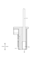
図1及び図2に示すように、実施形態1に係るコネクタ構造1は、図示しない相手側コネクタに嵌合されるコネクタ2と、コネクタ2の後側に取り付けられる電線カバー3とを有している。
(1) Connector structure As shown in FIGS. 1 and 2, the
図3及び図4に示すように、コネクタ2は、絶縁性の合成樹脂製であって、上下に扁平な略直方体形状をなしている。コネクタ2には前後方向に延びる複数のキャビティ10が形成されている。複数のキャビティ10は左右方向に間隔を空けて並んでいる。キャビティ10は前方及び後方に開口している。
As shown in FIGS. 3 and 4, the
コネクタ2の上面には、弾性変形可能なロックアーム11が、コネクタ2の前端部から後方に延びて形成されている。ロックアーム11の上面には相手側コネクタの係合穴に係合されるロック部12が上方に突出して形成されている。ロックアーム11の後端部には、左右方向に延びた板状をなす把持部15が設けられている。作業者が把持部15に指を掛けることにより、ロックアーム11を弾性変形させることができる。
コネクタ2の上面には上方に突出する保護リブ14が形成されている。保護リブ14のコネクタ2からの突出高さ寸法は、ロックアーム11のコネクタ2の上面からの突出高さ寸法よりも大きく設定されている。
An elastically
A
コネクタ2の後端部には、上下方向及び左右方向に突出するエンドリブ16が設けられている。コネクタ2の上面においては、エンドリブ16はコネクタ2の左右両端部に設けられている。コネクタ2の左右両側面においては、エンドリブ16は上下方向の全域に設けられている。コネクタ2の下面においては、エンドリブ16は左右方向の全域に設けられている。
An
図5に示すように、各キャビティ10の内部には金属製の雌端子17(端子の一例)が収容されている。雌端子17は前後方向に延びる角筒状をなしている。雌端子17の後端部には電線4が接続されている。電線4は芯線の外周面を絶縁性の合成樹脂からなる絶縁被覆で包囲してなる。電線4の端末部分は絶縁被覆が皮剥ぎされて、芯線が露出している。実施形態1に係る芯線は、1本の金属線からなる、いわゆる単芯線である。芯線は、複数の金属細線を撚り合わせてなる撚線であってもよい。電線4は芯線が圧着、溶接、半田付けなどによって雌端子17に接続されており、雌端子17から後側に延びている。
図5では示されていないが、キャビティ10の内部において雌端子17の後側には雌端子17が後側に抜けることを防止する抜け止め部が設けられている。このため、雌端子17は電線4が後側に引っ張られても図5に示す位置より後側には移動しない。
As shown in FIG. 5, a metal female terminal 17 (an example of a terminal) is housed inside each
Although not shown in FIG. 5, a retaining portion is provided on the rear side of the
図1に示すように、電線カバー3はコネクタ2から後側に引き出された複数の電線4の向きを右側(嵌合方向と交差する方向の一例)に90度曲げるためのものである。電線カバー3は、図1に示す第1のカバー21及び第2のカバー22、並びに、図6に示す補助部材24を備えている。
図1に示すように、第1のカバー21と第2のカバー22とは電線カバー3のハウジング23を構成している。
図6に示すように、第1のカバー21は底壁部30、底壁部30の外周縁部から立ち上がっている4つの側壁部31(31A、31B、31C、31D)を有している。底壁部30は上面視で底辺51、左辺52、右辺(図示せず)、上辺53の4つの辺を有する四角形状であり、右辺が左辺52より長くなっている。このため上辺53は底辺51の左端から右端に向かって底辺51から離間するように傾斜している。具体的には、上辺53は底辺51に対して45度の角度で傾斜している。45度は一例である。上辺53の角度は適宜に決定できる。以降の説明では上辺53のことを斜辺53という。
As shown in FIG. 1, the
As shown in FIG. 1, the
As shown in FIG. 6, the
底壁部30の斜辺53に沿って立ち上がっている側壁部31C(規制部の一例)は、後述する補助部材24と協働してハウジング23内での電線4の前後方向の動きを規制する。図2に示すように、側壁部31Cの外面には第2のカバー22に形成されているロックアーム60が係止される係止突起32が形成されている。
図6に示すように、底壁部30の底辺51に沿って立ち上がっている側壁部31Aの中央部分は矩形状に切り欠かれている。矩形状に切り欠かれている部分の左右方向の幅は左右方向に並ぶ複数の電線4の左右方向の幅より広くなっており、複数の電線4をハウジング23の内部に挿入するための挿入口36を構成している。
A
As shown in FIG. 6, the center portion of the
底壁部30の右辺に沿って立ち上がっている側壁部31Dは前後方向の中央部分が矩形状に切り欠かれている。切り欠かれている部分の前後方向の幅は、90度に曲げられて右側に延びる複数の電線4の前後方向の幅より広くなっており、挿入口36から挿入された複数の電線4が右側に導出される導出口37を構成している。
底壁部30の左辺52に沿って立ち上がっている側壁部31Bには、後述する補助部材24に設けられている被係止部66が係止される係止穴35が形成されている。
The
A locking
第1のカバー21の前側には、コネクタ2のエンドリブ16が上側から差し込まれる溝を有する第1のガイド部38が一体に設けられている。具体的には、第1のガイド部38は側壁部31Dの外面から前側に張り出す右壁部38A、側壁部31Bの外面から前側に張り出す左壁部38B、及び、底壁部30の下面から前側に張り出す下壁部38Cを有している。
右壁部38Aの左側を向く面には上下方向に延びる縦溝39が形成されている。左壁部38Bの右側を向く面には上下方向に延びる縦溝39が形成されている。下壁部38Cの上側を向く面には左右方向に延びる横溝40が形成されている。これらの溝39及び40の前後方向の幅はエンドリブ16の前後方向の幅と略一致している。
A
A
図1に示すように、第2のカバー22は複数の電線4の上側に配されており、複数の電線4を挟んで第1のカバー21と対向している。上面視で第2のカバー22の外周形状は第1のカバー21の外周形状と略一致している。
図6に示すように、第2のカバー22は概ね平板状である。第2のカバー22はヒンジ25によって第1のカバー21に回動可能に連結されている。第2のカバー22の前側には、コネクタ2のエンドリブ16の上端部が差し込まれる溝42を有する第2のガイド部43が一体に設けられている。具体的には、第2のガイド部43は、第2のカバー22の右側の端面から前側に張り出す右側ガイド部43Aと、第2のカバー22の左側の端面から前側に張り出す左側ガイド部43Bとを有している。右側ガイド部43Aの左側を向く面には上下方向に延びる縦溝42が形成されている。左側ガイド部43Bの右側を向く面には上下方向に延びる縦溝42が形成されている。これらの溝42の前後方向の幅はエンドリブ16の前後方向の幅と略一致している。これらの縦溝42の下側にはエンドリブ16が上側に抜けることを防止するための壁44が形成されている。
As shown in FIG. 1, the
As shown in FIG. 6, the
図2及び図6に示すように、第2のカバー22の後側には、側壁部31Cの外面に形成されている係止突起32に係止される弾性変形可能なロックアーム60が形成されている。
As shown in FIGS. 2 and 6, an elastically
図6を参照して、補助部材24について説明する。補助部材24はハウジング23の内部で各電線4の立体的な曲げを補助するものである。補助部材24は第2のカバー22と電線4との間に配される板状の部材であり、ヒンジ26によって第1のカバー21の側壁部31Dに回動可能に連結されている。補助部材24の外周形状は、上側から見てハウジング23の内部空間の形状と略一致しているが、前後方向の幅がハウジング23の内部空間の前後方向の幅より狭くなっている。
The
補助部材24が回動されてハウジング23の内部に収容された状態では、補助部材24の嵌合方向後側の縁部は、左右方向の左側(第1の直交方向のいずれか一方の側の一例)から右側(他方の側の一例)に向かって嵌合方向後側に傾斜した状態となる。
補助部材24の嵌合方向後側の縁部には複数の凹部65が形成されている。凹部65の数は電線4の数と同じである。各凹部65は上面視で直角三角形状に形成されている。直角三角形状の凹部65が複数連なって形成されていることにより、補助部材24の嵌合方向後側の縁部は階段状に形成されている。
When the
A plurality of
補助部材24の右端部には上側に向かって突出する弾性変形可能な被係止部66が一体に設けられている。被係止部66は上側に向かって延びる腕部と腕部の先端部から右側に張り出す係止爪とを有している。補助部材24が閉じられると係止爪が第1のカバー21の側壁部31Bに形成されている係止穴35に係止されることによって補助部材24が第1のカバー21にロックされる。
An elastically deformable locked
(2)電線カバーの取り付け
図7に示すように、コネクタ2への電線カバー3の取り付けでは、先ず、コネクタ2のエンドリブ16が電線カバー3の第1のガイド部38の溝39及び40に差し込まれることによって電線カバー3がコネクタ2に取り付けられる。電線カバー3がコネクタ2に取り付けられると、コネクタ2の後側から引き出されている電線4は第1のカバー21の上面に沿って後側に延び、第1のカバー21の側壁部31Cを乗り越えて更に後側に延びた状態となる。
(2) Attaching the wire cover As shown in FIG. 7, when attaching the
次に、図8に示すように、各電線4がそれぞれ側壁部31Cの内面(斜面)に突き当たる位置で上に90度曲げられ、その状態で補助部材24が閉じられる。これにより、挿入口36から挿入されて嵌合方向後側に延びる各電線4が、補助部材24を通過した位置で補助部材24に補助されて上側(第2のカバー22側)に曲がった状態となる。そして、上側に曲がった電線4が凹部65を通過して上側に延びる状態となる。
Next, as shown in FIG. 8, each
次に、図9に示すように、凹部65を通過した各電線4が補助部材24に補助されて右側(導出口37側の一例)に90度曲げられ、導出口37から外に引き出される。
次に、図1及び図2及びに示すように、各電線4が導出口37から引き出されている状態で第2のカバー22が閉じられる。第2のカバー22が閉じられると、第2のカバー22のロックアーム60が係止突起32に係止されることによって第1のカバー21と第2のカバー22とがロックされる。
Next, as shown in FIG. 9, each
Next, as shown in FIGS. 1 and 2, the
(3)実施形態の効果
実施形態1の電線カバー3によると、電線カバー3の内部で各電線4がそれぞれ補助部材24によって曲がりを補助されているので、各電線4の曲がりを均一にできる。このため、電線4が引っ張られたときに各電線4に作用する力が均一化され、曲がりの外側となる電線4に大きな力が作用することを抑制できる。
更に、電線カバー3は各電線4を補助部材24によって補助して立体的に曲げている。電線4を立体的に曲げると電線4が2回以上曲げられるので、1回だけ曲げる場合に比べて電線4と補助部材24との間に摩擦が生じる箇所が増える。このため、電線4をコネクタ2の雌端子17から引き抜く力を低減できる。また、電線4を立体的に曲げると、電線4と補助部材24との間に摩擦が生じる箇所を増やしつつ電線4を嵌合方向に交差する方向に引き出すことを、平面的に2回以上曲げる場合に比べてコンパクトな構成で実現できる。
よって実施形態1の構成によると、コネクタ2から引き出された複数の電線4を嵌合方向に交差する方向に引き出す電線カバー3において、電線4に対して雌端子17の抜け方向の力が生じても電線4が雌端子17から抜け難くすることをコンパクトな構成で実現できる。
(3) Effects of Embodiment According to the
Furthermore, the
Therefore, according to the configuration of
電線カバー3によると、電線4が第2のカバー22側に曲がる箇所(電線4が上側に曲がる個所)で電線4と補助部材24との間に摩擦が生じ、第2のカバー22側に曲がった各電線4が導出口37側に曲がる箇所(電線4が右側に曲がる個所)で電線4と補助部材24との間に摩擦が生じる。すなわち、電線カバー3によると、電線4が立体的に曲がっていることによって電線4と補助部材24との間に2か所で摩擦が生じる。このため、電線4を1回だけ平面的に曲げる場合に比べて雌端子17から電線4を引き抜く力を低減できる。
According to the
電線カバー3によると、補助部材24の嵌合方向後側の縁部が傾斜しているので、電線4を立体的に曲げつつ嵌合方向に対して直角に引き出すことあるいはそれに近い角度で引き出すことができる。
According to the
電線カバー3によると、凹部65によって電線4の位置が規制されるので、ハウジング23内での電線4の動きを抑制できる。
According to the
電線カバー3によると、電線4毎に凹部65が形成されているので、例えば2つの電線4毎あるいは3つの電線4毎などのように複数の電線4毎に1つの凹部を設ける場合に比べ、ハウジング23内での電線4の動きをより確実に抑制できる。
According to the
電線カバー3によると、上下方向(第2の直交方向)から見て、凹部65が直角三角形状であるので、直角三角形の直角を構成している2辺のうちの一方の辺を支点にして電線4を曲げ、当該一方の辺を支点にして曲げられた電線4が凹部を通過した後、他方の辺を支点にして電線4を曲げることにより、電線4を嵌合方向に対して直角に引き出すことあるいはそれに近い角度で引き出すことがより容易になる。
According to the
電線カバー3によると、補助部材24がヒンジ26によってハウジング23に連結されているので、補助部材24とハウジング23とが連結されていない場合に比べ、電線カバー3を取り付ける作業の作業効率が向上する。
According to the
電線カバー3によると、補助部材24と側壁部31C(規制部)とが協働して電線4の前後方向の動きを規制することにより、ハウジング23内での電線4の動きをより確実に抑制できる。
According to the
実施形態1のコネクタ2によると、コネクタ2から引き出された複数の電線4を嵌合方向に交差する方向に引き出す電線カバー3を備えるコネクタ構造1において、電線4が引っ張られた場合に電線4がコネクタ2の雌端子17から抜ける可能性を低減することをコンパクトな構成で実現できる。
According to the
<実施形態2>
図10に示すように、実施形態2に係るコネクタ構造201は、コネクタ202と電線カバー203とを備えている。コネクタ202は複数のキャビティ10が上下2段に分かれて設けられている。上段のキャビティ10は互いに左右方向に離間して一列に配されている。下段のキャビティ10も互いに左右方向に離間して一列に配されている。
<
As shown in FIG. 10, a
図11を参照して、電線カバー203の内部について説明する。実施形態2ではコネクタ202の後側から電線4が上下2段に引き出されているが、電線カバー203の内部ではそれらの電線4は上下に仕切られておらず、上段の電線4も下段の電線4も第1のカバー221と補助部材224との間を通って後側に延びている。
実施形態2に係るコネクタ構造201はその他の点において実施形態1と実質的に同一である。
The inside of the
The
<実施形態3>
図12に示すように、実施形態3に係る電線カバー303は第1のカバー21と第2のカバー22とが補助部材24を介して連結されている。具体的には、第1のカバー21はヒンジ301を介して補助部材24に連結されている。第2のカバー22はヒンジ302を介して補助部材24に連結されている。実施形態3はその他の点において実施形態1と実質的に同一である。
<
As shown in FIG. 12, in the
<他の実施形態>
本明細書によって開示される技術は上記記述及び図面によって説明した実施形態に限定されるものではなく、例えば次のような実施形態も本明細書によって開示される技術的範囲に含まれる。
<Other embodiments>
The technology disclosed by this specification is not limited to the embodiments described above and illustrated in the drawings; for example, the following embodiments are also included within the technical scope disclosed by this specification.
(1)上記実施形態1の補助部材24は1つの電線4ごとに1つの凹部65が設けられている。これに対し、図13に示す補助部材424のように、複数(図13では2つ)の電線4ごとに1つの凹部465を設け、複数の電線4が同じ凹部465を通過してもよい。
(1) In the
(2)上記実施形態1の補助部材24は凹部65を備えている。これに対し、図14に示す補助部材524のように、凹部565を1つだけ備えていてもよい。あるいは、補助部材24は凹部を備えていなくてもよい。
(2) The
(3)上記実施形態1の補助部材24の凹部は直角三角形状である。これに対し、図15に示す凹部665ように半円状に形成されてもよい。
(3) The concave portion of the
(4)上記実施形態1の電線カバー3は斜辺53を有している。これに対し、図16に示す電線カバー703のように斜辺53を有していなくてもよい。この場合、補助部材724も電線カバー703の形状に合わせて斜辺を有していない形状となる。
(4) The
(5)上記実施形態1では補助部材24が電線カバーと一体に形成されているが、補助部材24はコネクタ2と一体に形成されてコネクタ2から嵌合方向後側に延びていてもよい。そして、後側に延びた補助部材24が電線カバー3のハウジング23に挿入されて電線4の立体的な曲げを補助してもよい。
(5) In the first embodiment, the
(6)上記実施形態1では上下方向(第2の直交方向)から見て凹部65が直角三角形状である場合を例に説明したが、凹部65は直角三角形以外の三角形状であってもよい。
(6) In the first embodiment, the
1: コネクタ構造
2: コネクタ
3: 電線カバー
4: 電線
10: キャビティ
11: ロックアーム
12: ロック部
14: 保護リブ
15: 把持部
16: エンドリブ
17: 雌端子(端子の一例)
21: 第1のカバー
22: 第2のカバー
23: ハウジング
24: 補助部材
25: ヒンジ
26: ヒンジ
30: 底壁部
31: 側壁部
31A: 側壁部
31B: 側壁部
31C: 側壁部(規制部の一例)
31D: 側壁部
32: 係止突起
35: 係止穴
36: 挿入口
37: 導出口
38: ガイド部
38A: 右壁部
38B: 左壁部
38C: 下壁部
39: 縦溝
40: 横溝
42: 縦溝
43: ガイド部
43A: 右側ガイド部
43B: 左側ガイド部
44: 壁
51: 底辺
52: 左辺
53: 上辺
60: ロックアーム
65: 凹部
66: 被係止部
201: コネクタ構造
202: コネクタ
203: 電線カバー
221: 第1のカバー
224: 補助部材
301: ヒンジ
302: ヒンジ
303: 電線カバー
424: 補助部材
465: 凹部
524: 補助部材
565: 凹部
665: 凹部
703: 電線カバー
724: 補助部材
1: Connector structure 2: Connector 3: Wire cover 4: Wire 10: Cavity 11: Lock arm 12: Lock part 14: Protective rib 15: Grip part 16: End rib 17: Female terminal (an example of a terminal)
21: First cover 22: Second cover 23: Housing 24: Auxiliary member 25: Hinge 26: Hinge 30: Bottom wall 31:
31D: Side wall portion 32: Locking projection 35: Locking hole 36: Insertion port 37: Outlet port 38:
Claims (8)
前記コネクタは、前記嵌合方向に直交する第1の直交方向に互いに離間して配されている複数の端子と、各前記端子に接続されて前記嵌合方向後側から引き出されている複数の電線とを有し、
当該電線カバーは、
前記複数の電線が挿入される挿入口と、前記挿入口から挿入された前記複数の電線が前記嵌合方向と交差する方向に導出される導出口とを有するハウジングと、
前記ハウジングの内部で各前記電線の立体的な曲げを補助する補助部材と、
を備え、
前記ハウジングの内部で各前記電線が前記補助部材に補助されて立体的に曲げられて前記導出口から導出されており、
前記ハウジングは、
前記複数の電線に対して前記嵌合方向及び前記第1の直交方向の両方に直交する第2の直交方向の一方の側に配される第1のカバーと、
前記複数の電線を挟んで前記第1のカバーと対向する第2のカバーと、
を有し、
前記補助部材は前記第2のカバーと前記電線との間に配される板状の部材であり、
前記挿入口から挿入されて前記嵌合方向後側に延びる各前記電線が前記補助部材を通過した位置で前記補助部材に補助されて前記第2のカバー側に曲がっており、前記第2のカバー側に曲がった各前記電線が前記補助部材に補助されて前記導出口側に曲がっている、電線カバー。 An electric wire cover that is attached to the rear side in the mating direction of a connector that is mated to a mating connector,
The connector includes a plurality of terminals spaced apart from each other in a first orthogonal direction perpendicular to the fitting direction, and a plurality of terminals connected to each terminal and pulled out from the rear side in the fitting direction. It has an electric wire,
The wire cover is
a housing having an insertion port into which the plurality of electric wires are inserted; and an outlet through which the plurality of electric wires inserted from the insertion port are led out in a direction intersecting the fitting direction;
an auxiliary member that assists three-dimensional bending of each of the electric wires inside the housing;
Equipped with
Each of the electric wires is assisted by the auxiliary member and bent three-dimensionally inside the housing and led out from the outlet ,
The housing includes:
a first cover disposed on one side of the plurality of electric wires in a second orthogonal direction that is orthogonal to both the fitting direction and the first orthogonal direction;
a second cover facing the first cover with the plurality of electric wires in between;
has
The auxiliary member is a plate-shaped member disposed between the second cover and the electric wire,
Each of the electric wires inserted from the insertion opening and extending rearward in the fitting direction is assisted by the auxiliary member and bent toward the second cover at a position where it passes through the auxiliary member, and An electric wire cover , wherein each of the electric wires bent to the side is assisted by the auxiliary member and bent toward the outlet side .
前記補助部材を通過した位置で前記補助部材に補助されて前記第2のカバー側に曲がった各前記電線が前記凹部を通過している、請求項2に記載の電線カバー。 one or more recesses are formed in the edge of the auxiliary member,
The electric wire cover according to claim 2, wherein each of the electric wires, which are assisted by the auxiliary member and bent toward the second cover at a position passing through the auxiliary member, passes through the recess .
前記コネクタの前記嵌合方向後側に取り付けられる請求項1から請求項7のいずれか一項に記載の電線カバーと、
を備えるコネクタ構造。 A connector to be mated with a mating connector, comprising a plurality of terminals spaced apart from each other in a first orthogonal direction perpendicular to the mating direction, and a plurality of terminals connected to each terminal and rearward in the mating direction. a connector having a plurality of electric wires pulled out from the side;
The wire cover according to any one of claims 1 to 7, which is attached to the rear side of the connector in the fitting direction;
Connector structure with.
Priority Applications (4)
| Application Number | Priority Date | Filing Date | Title |
|---|---|---|---|
| JP2020104410A JP7398056B2 (en) | 2020-06-17 | 2020-06-17 | Wire cover and connector structure |
| PCT/JP2021/020224 WO2021256210A1 (en) | 2020-06-17 | 2021-05-27 | Electric wire cover and connector structure |
| US18/010,326 US20230231340A1 (en) | 2020-06-17 | 2021-05-27 | Wire cover and connector structure |
| CN202180042288.7A CN115699470A (en) | 2020-06-17 | 2021-05-27 | Wire cover and connector structure |
Applications Claiming Priority (1)
| Application Number | Priority Date | Filing Date | Title |
|---|---|---|---|
| JP2020104410A JP7398056B2 (en) | 2020-06-17 | 2020-06-17 | Wire cover and connector structure |
Publications (3)
| Publication Number | Publication Date |
|---|---|
| JP2021197311A JP2021197311A (en) | 2021-12-27 |
| JP2021197311A5 JP2021197311A5 (en) | 2022-10-19 |
| JP7398056B2 true JP7398056B2 (en) | 2023-12-14 |
Family
ID=79195913
Family Applications (1)
| Application Number | Title | Priority Date | Filing Date |
|---|---|---|---|
| JP2020104410A Active JP7398056B2 (en) | 2020-06-17 | 2020-06-17 | Wire cover and connector structure |
Country Status (4)
| Country | Link |
|---|---|
| US (1) | US20230231340A1 (en) |
| JP (1) | JP7398056B2 (en) |
| CN (1) | CN115699470A (en) |
| WO (1) | WO2021256210A1 (en) |
Citations (3)
| Publication number | Priority date | Publication date | Assignee | Title |
|---|---|---|---|---|
| JP2004127813A (en) | 2002-10-04 | 2004-04-22 | Sumitomo Wiring Syst Ltd | Connector |
| JP2007141725A (en) | 2005-11-21 | 2007-06-07 | Sumitomo Wiring Syst Ltd | Connector |
| JP6243926B2 (en) | 2013-12-12 | 2017-12-06 | 日立建機株式会社 | VEHICLE TRAVEL SYSTEM, METHOD USED BY PAPER VEHICLE STOP POSITION SETTING APPARATUS, AND CAR |
Family Cites Families (4)
| Publication number | Priority date | Publication date | Assignee | Title |
|---|---|---|---|---|
| JPH0317413Y2 (en) * | 1986-01-21 | 1991-04-12 | ||
| JP2767733B2 (en) * | 1993-02-15 | 1998-06-18 | 矢崎総業株式会社 | connector |
| JP2001076809A (en) * | 1999-09-09 | 2001-03-23 | Sumitomo Wiring Syst Ltd | Connector |
| JP5130170B2 (en) * | 2008-06-30 | 2013-01-30 | 矢崎総業株式会社 | Connector with cover |
-
2020
- 2020-06-17 JP JP2020104410A patent/JP7398056B2/en active Active
-
2021
- 2021-05-27 US US18/010,326 patent/US20230231340A1/en active Pending
- 2021-05-27 CN CN202180042288.7A patent/CN115699470A/en active Pending
- 2021-05-27 WO PCT/JP2021/020224 patent/WO2021256210A1/en active Application Filing
Patent Citations (3)
| Publication number | Priority date | Publication date | Assignee | Title |
|---|---|---|---|---|
| JP2004127813A (en) | 2002-10-04 | 2004-04-22 | Sumitomo Wiring Syst Ltd | Connector |
| JP2007141725A (en) | 2005-11-21 | 2007-06-07 | Sumitomo Wiring Syst Ltd | Connector |
| JP6243926B2 (en) | 2013-12-12 | 2017-12-06 | 日立建機株式会社 | VEHICLE TRAVEL SYSTEM, METHOD USED BY PAPER VEHICLE STOP POSITION SETTING APPARATUS, AND CAR |
Also Published As
| Publication number | Publication date |
|---|---|
| CN115699470A (en) | 2023-02-03 |
| JP2021197311A (en) | 2021-12-27 |
| US20230231340A1 (en) | 2023-07-20 |
| WO2021256210A1 (en) | 2021-12-23 |
Similar Documents
| Publication | Publication Date | Title |
|---|---|---|
| JP5381492B2 (en) | Female terminal bracket | |
| TWI463747B (en) | Connector with cover | |
| TW200818625A (en) | Connector | |
| JP2002313472A (en) | Connector | |
| JP6991575B2 (en) | Connector assembly | |
| JP6280080B2 (en) | Connector with aligning plate | |
| JP7398056B2 (en) | Wire cover and connector structure | |
| CN112909608B (en) | Terminal fitting | |
| JP2010049984A (en) | Terminal metal fitting and electric wire with terminal metal fitting | |
| JP6115449B2 (en) | Terminal fitting | |
| JP6218912B2 (en) | Electrical connector assembly | |
| JP7245432B2 (en) | connector | |
| JP3757801B2 (en) | Male connector | |
| JP6179451B2 (en) | connector | |
| JP6607393B2 (en) | Terminal fitting | |
| JP5104639B2 (en) | connector | |
| JP5986933B2 (en) | Terminal | |
| JP7414363B2 (en) | connector | |
| JP7381320B2 (en) | connector | |
| JP7435329B2 (en) | terminal fittings | |
| JP5394696B2 (en) | connector | |
| JP7339184B2 (en) | protector and wire harness | |
| US11728589B2 (en) | Connector | |
| WO2024057856A1 (en) | Connector | |
| JP6767214B2 (en) | Assembling structure of connector |
Legal Events
| Date | Code | Title | Description |
|---|---|---|---|
| A521 | Request for written amendment filed |
Free format text: JAPANESE INTERMEDIATE CODE: A523 Effective date: 20221007 |
|
| A621 | Written request for application examination |
Free format text: JAPANESE INTERMEDIATE CODE: A621 Effective date: 20221130 |
|
| A131 | Notification of reasons for refusal |
Free format text: JAPANESE INTERMEDIATE CODE: A131 Effective date: 20230808 |
|
| A521 | Request for written amendment filed |
Free format text: JAPANESE INTERMEDIATE CODE: A523 Effective date: 20231004 |
|
| TRDD | Decision of grant or rejection written | ||
| A01 | Written decision to grant a patent or to grant a registration (utility model) |
Free format text: JAPANESE INTERMEDIATE CODE: A01 Effective date: 20231102 |
|
| A61 | First payment of annual fees (during grant procedure) |
Free format text: JAPANESE INTERMEDIATE CODE: A61 Effective date: 20231115 |
|
| R150 | Certificate of patent or registration of utility model |
Ref document number: 7398056 Country of ref document: JP Free format text: JAPANESE INTERMEDIATE CODE: R150 |