JP7397860B2 - Humidifier with protection against penetration for use in CPAP therapy - Google Patents
Humidifier with protection against penetration for use in CPAP therapy Download PDFInfo
- Publication number
- JP7397860B2 JP7397860B2 JP2021516780A JP2021516780A JP7397860B2 JP 7397860 B2 JP7397860 B2 JP 7397860B2 JP 2021516780 A JP2021516780 A JP 2021516780A JP 2021516780 A JP2021516780 A JP 2021516780A JP 7397860 B2 JP7397860 B2 JP 7397860B2
- Authority
- JP
- Japan
- Prior art keywords
- lid
- housing
- gas flow
- water chamber
- patient
- Prior art date
- Legal status (The legal status is an assumption and is not a legal conclusion. Google has not performed a legal analysis and makes no representation as to the accuracy of the status listed.)
- Active
Links
- 238000011513 continuous positive airway pressure therapy Methods 0.000 title 1
- 230000035515 penetration Effects 0.000 title 1
- XLYOFNOQVPJJNP-UHFFFAOYSA-N water Substances O XLYOFNOQVPJJNP-UHFFFAOYSA-N 0.000 claims description 68
- 230000029058 respiratory gaseous exchange Effects 0.000 claims description 46
- 230000007246 mechanism Effects 0.000 claims description 17
- 230000000241 respiratory effect Effects 0.000 claims description 14
- 230000002093 peripheral effect Effects 0.000 claims description 2
- 239000007789 gas Substances 0.000 description 59
- 238000000034 method Methods 0.000 description 6
- 201000002859 sleep apnea Diseases 0.000 description 6
- 206010021079 Hypopnoea Diseases 0.000 description 5
- 230000000670 limiting effect Effects 0.000 description 5
- 238000002560 therapeutic procedure Methods 0.000 description 4
- 208000008784 apnea Diseases 0.000 description 3
- 230000000712 assembly Effects 0.000 description 3
- 238000000429 assembly Methods 0.000 description 3
- 238000010586 diagram Methods 0.000 description 3
- 208000037265 diseases, disorders, signs and symptoms Diseases 0.000 description 3
- 208000035475 disorder Diseases 0.000 description 3
- CURLTUGMZLYLDI-UHFFFAOYSA-N Carbon dioxide Chemical compound O=C=O CURLTUGMZLYLDI-UHFFFAOYSA-N 0.000 description 2
- 206010041235 Snoring Diseases 0.000 description 2
- 206010063968 Upper airway resistance syndrome Diseases 0.000 description 2
- QVGXLLKOCUKJST-UHFFFAOYSA-N atomic oxygen Chemical compound [O] QVGXLLKOCUKJST-UHFFFAOYSA-N 0.000 description 2
- 238000010276 construction Methods 0.000 description 2
- 230000000414 obstructive effect Effects 0.000 description 2
- 208000001797 obstructive sleep apnea Diseases 0.000 description 2
- 229910052760 oxygen Inorganic materials 0.000 description 2
- 239000001301 oxygen Substances 0.000 description 2
- 230000036961 partial effect Effects 0.000 description 2
- 230000009467 reduction Effects 0.000 description 2
- 230000001225 therapeutic effect Effects 0.000 description 2
- 238000009423 ventilation Methods 0.000 description 2
- 208000000884 Airway Obstruction Diseases 0.000 description 1
- 241000473391 Archosargus rhomboidalis Species 0.000 description 1
- 206010007559 Cardiac failure congestive Diseases 0.000 description 1
- 208000003417 Central Sleep Apnea Diseases 0.000 description 1
- 208000007590 Disorders of Excessive Somnolence Diseases 0.000 description 1
- 206010019280 Heart failures Diseases 0.000 description 1
- 102000001554 Hemoglobins Human genes 0.000 description 1
- 108010054147 Hemoglobins Proteins 0.000 description 1
- 206010062519 Poor quality sleep Diseases 0.000 description 1
- 206010064911 Pulmonary arterial hypertension Diseases 0.000 description 1
- 208000008166 Right Ventricular Dysfunction Diseases 0.000 description 1
- 208000010340 Sleep Deprivation Diseases 0.000 description 1
- 206010041349 Somnolence Diseases 0.000 description 1
- 230000002411 adverse Effects 0.000 description 1
- 230000037007 arousal Effects 0.000 description 1
- 206010003119 arrhythmia Diseases 0.000 description 1
- 230000006793 arrhythmia Effects 0.000 description 1
- 210000004556 brain Anatomy 0.000 description 1
- 229910002092 carbon dioxide Inorganic materials 0.000 description 1
- 239000001569 carbon dioxide Substances 0.000 description 1
- 208000010877 cognitive disease Diseases 0.000 description 1
- 238000004891 communication Methods 0.000 description 1
- 230000008878 coupling Effects 0.000 description 1
- 238000010168 coupling process Methods 0.000 description 1
- 238000005859 coupling reaction Methods 0.000 description 1
- 230000003247 decreasing effect Effects 0.000 description 1
- 230000001419 dependent effect Effects 0.000 description 1
- 230000000694 effects Effects 0.000 description 1
- 239000012530 fluid Substances 0.000 description 1
- 210000001061 forehead Anatomy 0.000 description 1
- 230000014509 gene expression Effects 0.000 description 1
- 210000003128 head Anatomy 0.000 description 1
- 230000003434 inspiratory effect Effects 0.000 description 1
- 230000003993 interaction Effects 0.000 description 1
- 210000004072 lung Anatomy 0.000 description 1
- 230000014759 maintenance of location Effects 0.000 description 1
- 238000004519 manufacturing process Methods 0.000 description 1
- 238000012986 modification Methods 0.000 description 1
- 230000004048 modification Effects 0.000 description 1
- 210000003205 muscle Anatomy 0.000 description 1
- 210000001034 respiratory center Anatomy 0.000 description 1
- 208000023504 respiratory system disease Diseases 0.000 description 1
- 230000006814 right ventricular dysfunction Effects 0.000 description 1
- 238000007789 sealing Methods 0.000 description 1
- 208000024891 symptom Diseases 0.000 description 1
- 210000001519 tissue Anatomy 0.000 description 1
- 238000004448 titration Methods 0.000 description 1
Images


Classifications
-
- A—HUMAN NECESSITIES
- A61—MEDICAL OR VETERINARY SCIENCE; HYGIENE
- A61M—DEVICES FOR INTRODUCING MEDIA INTO, OR ONTO, THE BODY; DEVICES FOR TRANSDUCING BODY MEDIA OR FOR TAKING MEDIA FROM THE BODY; DEVICES FOR PRODUCING OR ENDING SLEEP OR STUPOR
- A61M16/00—Devices for influencing the respiratory system of patients by gas treatment, e.g. mouth-to-mouth respiration; Tracheal tubes
- A61M16/10—Preparation of respiratory gases or vapours
- A61M16/14—Preparation of respiratory gases or vapours by mixing different fluids, one of them being in a liquid phase
- A61M16/16—Devices to humidify the respiration air
- A61M16/162—Water-reservoir filling system, e.g. automatic
-
- A—HUMAN NECESSITIES
- A61—MEDICAL OR VETERINARY SCIENCE; HYGIENE
- A61M—DEVICES FOR INTRODUCING MEDIA INTO, OR ONTO, THE BODY; DEVICES FOR TRANSDUCING BODY MEDIA OR FOR TAKING MEDIA FROM THE BODY; DEVICES FOR PRODUCING OR ENDING SLEEP OR STUPOR
- A61M16/00—Devices for influencing the respiratory system of patients by gas treatment, e.g. mouth-to-mouth respiration; Tracheal tubes
- A61M16/10—Preparation of respiratory gases or vapours
- A61M16/14—Preparation of respiratory gases or vapours by mixing different fluids, one of them being in a liquid phase
- A61M16/16—Devices to humidify the respiration air
-
- A—HUMAN NECESSITIES
- A61—MEDICAL OR VETERINARY SCIENCE; HYGIENE
- A61M—DEVICES FOR INTRODUCING MEDIA INTO, OR ONTO, THE BODY; DEVICES FOR TRANSDUCING BODY MEDIA OR FOR TAKING MEDIA FROM THE BODY; DEVICES FOR PRODUCING OR ENDING SLEEP OR STUPOR
- A61M16/00—Devices for influencing the respiratory system of patients by gas treatment, e.g. mouth-to-mouth respiration; Tracheal tubes
- A61M16/0057—Pumps therefor
- A61M16/0066—Blowers or centrifugal pumps
- A61M16/0069—Blowers or centrifugal pumps the speed thereof being controlled by respiratory parameters, e.g. by inhalation
-
- A—HUMAN NECESSITIES
- A61—MEDICAL OR VETERINARY SCIENCE; HYGIENE
- A61M—DEVICES FOR INTRODUCING MEDIA INTO, OR ONTO, THE BODY; DEVICES FOR TRANSDUCING BODY MEDIA OR FOR TAKING MEDIA FROM THE BODY; DEVICES FOR PRODUCING OR ENDING SLEEP OR STUPOR
- A61M2205/00—General characteristics of the apparatus
- A61M2205/21—General characteristics of the apparatus insensitive to tilting or inclination, e.g. spill-over prevention
Landscapes
- Health & Medical Sciences (AREA)
- Emergency Medicine (AREA)
- Pulmonology (AREA)
- Engineering & Computer Science (AREA)
- Anesthesiology (AREA)
- Biomedical Technology (AREA)
- Heart & Thoracic Surgery (AREA)
- Hematology (AREA)
- Life Sciences & Earth Sciences (AREA)
- Animal Behavior & Ethology (AREA)
- General Health & Medical Sciences (AREA)
- Public Health (AREA)
- Veterinary Medicine (AREA)
- Respiratory Apparatuses And Protective Means (AREA)
- Air Humidification (AREA)
Description
本発明は、加湿されたガス流を患者の気道に送出するための気道圧力支援システムにおいて使用するための加湿器に関し、より詳細には、そのような加湿器の入口から外への水の流れを防止するための構成に関する。 The present invention relates to a humidifier for use in an airway pressure support system for delivering a humidified gas flow to a patient's airway, and more particularly to a humidifier for use in an airway pressure support system for delivering a humidified gas flow into a patient's airway, and more particularly to a humidifier for use in an airway pressure support system for delivering a humidified gas flow to a patient's airway, and more particularly to Regarding the configuration for preventing.
多くの人は、睡眠時の呼吸障害を患っている。睡眠時無呼吸は、世界中で何百万人もの人々が患っている上記の睡眠時の呼吸障害の一般的な例である。睡眠時無呼吸の1つの種類は、閉塞性睡眠時無呼吸(OSA)であり、これは、典型的には上気道又は咽頭領域である気道の閉塞によって呼吸ができないことにより、睡眠が繰り返し中断される状態である。気道の閉塞は、少なくとも一部は上気道セグメントを安定化させる筋肉の全般的な弛緩によるものであり、それにより組織が気道を崩壊させるためであると一般的に考えられている。もう一つの種類の睡眠時無呼吸症候群は、中枢性無呼吸であり、これは脳の呼吸中枢からの呼吸信号の欠如による呼吸停止である。閉塞性、中枢性又は閉塞性と中枢性との組み合わせである混合性を問わず、無呼吸状態は、呼吸の完全な停止又は略停止、例えば最大呼吸気流量の90%以上の減少と定義される。 Many people suffer from sleep breathing disorders. Sleep apnea is a common example of the above-mentioned sleep breathing disorder that affects millions of people worldwide. One type of sleep apnea is obstructive sleep apnea (OSA), in which sleep is repeatedly interrupted due to an inability to breathe due to obstruction of the airway, typically in the upper airway or pharyngeal area. It is a state in which It is generally believed that airway obstruction is due, at least in part, to general relaxation of the muscles that stabilize the upper airway segments, thereby allowing tissue to collapse the airway. Another type of sleep apnea is central apnea, which is a cessation of breathing due to a lack of respiratory signals from the brain's respiratory center. Apnea, whether obstructive, central, or a combination of obstructive and central, is defined as a complete or near-cessation of breathing, such as a 90% or more reduction in peak respiratory airflow. Ru.
睡眠時無呼吸で苦しめられている人々は、睡眠中、潜在的に重症レベルのヘモグロビン酸素飽和度の低下を伴い、睡眠断片化及び換気の完全な又は略完全な中断を断続的に経験する。これらの症状は、日中の過度の眠気、不整脈、肺動脈高血圧、うっ血性心不全及び/又は認知機能障害に臨床的に変換される。睡眠時無呼吸の他の結果は、右室機能不全、睡眠中と同様に、覚醒時の二酸化炭素の貯留、並びに連続して減少する動脈血酸素分圧を含む。睡眠時無呼吸を患う人は、潜在的に危険な機器を運転及び/又は操作している間、事故の危険性の増大と同様に、これらの要因による高い死亡率の危険性がある。 People suffering from sleep apnea experience intermittent sleep fragmentation and complete or near-complete disruption of ventilation during sleep, with potentially severe levels of hemoglobin oxygen desaturation. These symptoms translate clinically into excessive daytime sleepiness, arrhythmias, pulmonary arterial hypertension, congestive heart failure, and/or cognitive dysfunction. Other consequences of sleep apnea include right ventricular dysfunction, retention of carbon dioxide during sleep as well as during wakefulness, and a continuously decreasing arterial oxygen tension. People who suffer from sleep apnea are at risk of increased mortality from these factors, as well as an increased risk of accidents while driving and/or operating potentially dangerous equipment.
患者が気道の完全又は略完全な閉塞に苦しんでいなくても、例えば睡眠からの覚醒のような悪影響は、気道の部分的な閉塞があるだけで起こり得ることも知られている。気道の部分的な閉塞は、典型的には低呼吸と呼ばれる浅い呼吸をもたらす。低呼吸は、典型的には、最大呼吸気流の50%又はそれ以上の減少として定義される。他の種類の睡眠呼吸障害は、これらに限定されないが、上気道抵抗症候群(UARS)及び一般にいびきと呼ばれる咽頭壁の振動のような気道の振動が含まれる。 It is also known that even if a patient does not suffer from complete or near-total obstruction of the airway, adverse effects such as arousal from sleep can occur even if there is only partial obstruction of the airway. Partial obstruction of the airway typically results in shallow breathing, called hypopnea. Hypopnea is typically defined as a 50% or more reduction in peak respiratory airflow. Other types of sleep breathing disorders include, but are not limited to, upper airway resistance syndrome (UARS) and airway vibrations such as pharyngeal wall vibrations, commonly referred to as snoring.
患者の気道に持続陽圧呼吸(CPAP)を施すことにより睡眠呼吸障害を治療することはよく知られている。この陽圧は気道に効果的に"添え木(splint)"を当て、それにより肺への開放通路を維持する。患者に送出されるガスの圧力が患者の呼吸サイクルと共に変化する又は患者の呼吸努力と共に変化する陽圧療法を施し、患者に対する快適性を高めることも知られている。この圧力支持技術はバイレベル圧力支持と呼ばれ、患者に送出される吸気気道陽圧(IPAP)は呼気気道陽圧(EPAP)よりも高い。例えば患者が無呼吸及び/又は低呼吸を経験しているかどうかのような、患者の検出された状態に基づいて、圧力が自動的に調整される陽圧療法を施すことも知られている。この圧力支援技術は、圧力支援装置が呼吸障害を治療するのに必要なだけ高い圧力を患者に供給しようとするので、自動滴定タイプの圧力支援と呼ばれる。 It is well known to treat sleep disordered breathing by applying continuous positive airway pressure (CPAP) to a patient's airway. This positive pressure effectively "splints" the airways, thereby maintaining an open passageway to the lungs. It is also known to provide positive pressure therapy in which the pressure of the gas delivered to the patient varies with the patient's breathing cycle or with the patient's respiratory effort to increase comfort for the patient. This pressure support technique is called bilevel pressure support, where the inspiratory positive airway pressure (IPAP) delivered to the patient is higher than the expiratory positive airway pressure (EPAP). It is also known to administer positive pressure therapy in which the pressure is automatically adjusted based on a detected condition of the patient, such as whether the patient is experiencing apnea and/or hypopnea. This pressure support technique is referred to as autotitration type pressure support because the pressure support device attempts to provide the patient with as high a pressure as necessary to treat the respiratory disorder.
上述したような圧力支援療法は、患者の顔面上に柔らかく柔軟な封止クッションを有するマスク構成要素を含む患者インターフェース装置の配置を含む。マスク構成要素は、これらに限定されないが、患者の鼻を覆う鼻マスク、患者の鼻と口を覆う鼻/口マスク又は患者の顔を覆うフルフェイスマスクである。そのような患者インターフェース装置は、額支持体、頬パッド及び顎パッドのような他の患者接触構成要素を使用してもよい。患者インターフェース装置は通例、ヘッドギア構成要素により患者の頭部に固定される。患者インターフェース装置は、ガス送出チューブ又は導管に接続され、圧力支援装置を患者の気道と結び付けるので、呼吸ガス流が、圧力/フロー発生装置から患者の気道に送出され得る。 Pressure support therapy, as described above, involves placement of a patient interface device that includes a mask component with a soft, pliable sealing cushion over the patient's face. The mask component can be, but is not limited to, a nasal mask that covers the patient's nose, a nose/oral mask that covers the patient's nose and mouth, or a full face mask that covers the patient's face. Such patient interface devices may use other patient contacting components such as forehead supports, cheek pads, and chin pads. Patient interface devices are typically secured to the patient's head by a headgear component. The patient interface device is connected to the gas delivery tube or conduit and couples the pressure support device with the patient's airway so that a flow of respiratory gas can be delivered from the pressure/flow generating device to the patient's airway.
PAP装置により生成される比較的乾燥した圧縮空気を加湿するために、加湿器は、PAP装置とユーザインターフェースとの間に、又はPAP装置と一体でしばしば設けられる。在宅治療の人工呼吸器に使用される最も一般的な種類の加湿は、パスオーバー方式である。そのような方式において、CPAP装置からの空気は、加湿器を出て患者に移る前に、水室(water chamber)に流入し、水領域Wの上を流れる。これは、湿気を患者回路(チューブ+マスク)を介して患者まで運ぶ。水は、室温でも、高温でもよい。高温の手法は、水が加熱されるという事実により、空気中により多くの水を送るので、より人気がある。この種類の加湿器用の水は、一般に抵抗加熱器を使って加熱され、快適さのための複数の設定点がある。 To humidify the relatively dry compressed air produced by a PAP device, a humidifier is often provided between the PAP device and the user interface, or integral to the PAP device. The most common type of humidification used in home care ventilators is the passover method. In such a manner, air from the CPAP device enters a water chamber and flows over a water region W before exiting the humidifier and passing onto the patient. This carries the moisture through the patient circuit (tubing + mask) to the patient. The water may be at room temperature or at high temperature. The high temperature method is more popular as the fact that the water is heated sends more water into the air. The water for this type of humidifier is generally heated using a resistance heater and has multiple set points for comfort.
加湿器は通例、人工呼吸器(すなわち、CPAP)の一体となっている部分であり、故に、フロー発生器に直接接続されている可能性が最も高い。フロー発生器内には、水の浸入によって簡単にダメージを受ける可能性のある敏感な部品やアセンブリがある。これらは、モータ/送風器アセンブリ、圧力及び流量センサ、並びにダメージを受けることなく又は性能が低下することなく水に耐えるということができない他の電子装置を含む。使用中、患者は、治療中に湿気を気道に供給する水を含む水室と相互作用できなければならない。この相互作用中、加湿器のフォームファクタに依存して、水室内に収容される水が、意図せずに(例えば、誤注入、過充填等が原因で)フロー発生器に入る可能性がある。従って、このようなフロー発生器への水の侵入の発生を最小限に抑え、好ましくは排除する改良される装置の必要性がある。 Humidifiers are typically an integral part of a ventilator (ie, CPAP) and are therefore most likely connected directly to the flow generator. There are sensitive parts and assemblies within the flow generator that can be easily damaged by water ingress. These include motor/blower assemblies, pressure and flow sensors, and other electronic equipment that cannot withstand water without damage or loss of performance. During use, the patient must be able to interact with the water chamber containing water, which provides moisture to the airways during treatment. During this interaction, depending on the form factor of the humidifier, water contained within the water chamber may unintentionally enter the flow generator (e.g. due to misfilling, overfilling, etc.) . Accordingly, there is a need for an improved device that minimizes and preferably eliminates the occurrence of water ingress into such flow generators.
本発明の実施形態は、水室が依然として加湿器内に組み込まれ、フロー発生器に取り付けられている一方、水室が満たされることを可能にしながら、そのようなフロー発生器への水の侵入の可能性を最小限に抑える又は排除する。本発明の実施形態は、空気の道の経路が水室の蓋の旋回点を概ね通るように経路設定され、この蓋が上げられるとき、蓋が出口を水室の上方に位置決め、従って、水がフロー発生器に入る可能性を排除する。 Embodiments of the present invention reduce water ingress into such flow generators while still allowing the water chamber to be filled while being incorporated within the humidifier and attached to the flow generator. minimize or eliminate the possibility of Embodiments of the invention are configured such that the path of the air path is routed generally through the pivot point of the water chamber lid, so that when this lid is raised, the lid positions the outlet above the water chamber and thus eliminates the possibility of water entering the flow generator.
開示される概念の1つの態様として、患者に呼吸ガス流を供給するための装置が提供される。この装置は、ハウジング、このハウジング内に配され、呼吸ガス流を生成するように構成されるガス流発生器、このハウジング内に配され、その中に水を収容するように構成される水室を持つ加湿器であり、水室は水をこの水室に供給するための頂部開口を持っている、加湿器、蓋が水室の頂部開口を覆う第1の位置と、蓋が水室の頂部を覆わない第2の位置との間を蓋が移動可能であるように、前記ハウジングに結合される蓋、前記ガス流発生器から呼吸ガス流を受け取るように位置決め及び構成される第1の端部から、前記呼吸ガス流を前記水室内に放出するように位置決め及び構成される反対側の第2の端部まで延在する通路、並びに前記ハウジング上に位置決められ、前記水室からの呼吸ガス流を前記ハウジングから外に運ぶように構成される出口、を有する。 In one aspect of the disclosed concepts, an apparatus for providing a flow of breathing gas to a patient is provided. The apparatus includes a housing, a gas flow generator disposed within the housing and configured to produce a breathing gas flow, a water chamber disposed within the housing and configured to receive water therein. a humidifier with a water chamber having a top opening for supplying water to the water chamber; a first position in which the lid covers the top opening of the water chamber; and a first position in which the lid covers the top opening of the water chamber; a lid coupled to the housing such that the lid is movable between a second position not covering the top; a first lid positioned and configured to receive a breathing gas flow from the gas flow generator; a passageway extending from one end to an opposite second end positioned and configured to emit a flow of breathing gas into the water chamber; an outlet configured to convey a gas flow out of the housing.
前記蓋は、この蓋が回転軸の周りを回転可能であるようなヒンジ機構を介してハウジングに回転可能に結合される。 The lid is rotatably coupled to the housing via a hinge mechanism such that the lid is rotatable about an axis of rotation.
前記通路の一部は、ヒンジ機構により画定される。 A portion of the passageway is defined by a hinge mechanism.
前記ヒンジ機構は、前記回転軸を中心に配される概ね円筒形の円筒部分を有し、前記通路の一部は、円筒部分内に画定される中空部を有する。 The hinge mechanism has a generally cylindrical cylindrical portion disposed about the axis of rotation, and a portion of the passageway has a hollow portion defined within the cylindrical portion.
前記中空部は、この中空部に入る呼吸ガス流を最初に受け取るように位置決められる入口から延在し、この入口は、前記円筒部分の軸方向面上に配される。 The hollow portion extends from an inlet positioned to initially receive a flow of breathing gas entering the hollow portion, the inlet being arranged on an axial plane of the cylindrical portion.
前記中空部は、この中空部に入る呼吸ガス流を最初に受け取るように位置決められる入口から延在し、この入口は、前記円筒部分の円周面上に配される。 The hollow portion extends from an inlet positioned to initially receive a flow of breathing gas entering the hollow portion, the inlet being disposed on the circumferential surface of the cylindrical portion.
前記蓋が前記第1の位置に配されるとき、入口は、呼吸ガス流を受け取るように位置決められ、前記蓋が前記第2の位置に配されるとき、前記入口は、呼吸ガス流を受け取らないように位置決められる。 When the lid is placed in the first position, the inlet is positioned to receive a flow of breathing gas, and when the lid is placed in the second position, the inlet is positioned to receive a flow of breathing gas. Positioned so that it does not.
前記円筒部分は、前記蓋に固定して結合されてもよい。 The cylindrical portion may be fixedly coupled to the lid.
前記中空部は、入口から側面出口まで延在し、前記通路の一部は、前記側面出口から前記通路の反対側の第2の端部まで延在する概ね真っすぐな部分をさらに有する。 The hollow portion extends from an inlet to a side outlet, and the portion of the passageway further has a generally straight portion extending from the side outlet to an opposite second end of the passageway.
前記蓋は、内蓋を有し、前記装置は、外蓋が内蓋を覆う第1の位置と、外蓋が内蓋を覆わない第2の位置との間を外蓋が移動可能であるように、ハウジングに結合される外蓋をさらに有する。 The lid has an inner lid, and the device is configured such that the outer lid is movable between a first position in which the outer lid covers the inner lid and a second position in which the outer lid does not cover the inner lid. The housing further includes an outer lid coupled to the housing.
ハウジングは、第1のハウジング、及びこの第1のハウジングに選択的に結合される第2のハウジングを有し、ガス流発生器は、前記第1のハウジングに配され、加湿器は、前記第2のハウジングに配される。 The housing has a first housing and a second housing selectively coupled to the first housing, a gas flow generator disposed in the first housing, and a humidifier disposed in the first housing. 2 housing.
開示される概念のもう1つの態様として、患者の気道に呼吸ガス流を供給する際に使用する気道圧力支援システムが提供される。このシステムは、患者に呼吸ガス流を供給するための装置を有し、この装置は、ハウジング、前記ハウジング内に配され、呼吸ガス流を生成するために構成されるガス流発生器、前記ハウジング内に配され、加湿器はその中に水を収容するように構成される水室を持つ加湿器であり、水室がこの水室に水を供給するための頂部開口を持つ、加湿器、蓋が前記水室の頂部開口を覆う第1の位置と、蓋が前記水室の頂部開口を覆わない第2の位置との間を、蓋が移動可能であるように、前記ハウジングに結合される蓋、前記ガス流発生器から呼吸ガス流を受け取るように位置決め及び構成される第1の端部から、前記蓋に位置決められ、呼吸ガス流を前記水室内に放出するように構成される反対側の第2の端部まで延在する通路、並びに前記ハウジングに位置決められ、前記水室からの呼吸ガス流をハウジングから外に運ぶように構成される出口、を有する。前記システムは、前記装置の前記出口に結合される第1の端部及び反対側の第2の端部を持ち、前記第1の端部から前記第2の端部に呼吸ガス流を運ぶように構成される送出導管、並びに患者の気道に治療ガス流を供給するための前記送出導管の第2の端部に結合される患者インターフェース装置をさらに有する。 Another aspect of the disclosed concepts provides an airway pressure support system for use in providing a flow of breathing gas to a patient's airway. The system includes an apparatus for providing a flow of breathing gas to a patient, the apparatus comprising: a housing; a gas flow generator disposed within the housing and configured to generate a flow of breathing gas; a humidifier having a water chamber configured to receive water therein, the water chamber having a top opening for supplying water to the water chamber; The lid is coupled to the housing such that the lid is movable between a first position in which the lid covers a top opening of the water chamber and a second position in which the lid does not cover the top opening of the water chamber. a lid positioned and configured to receive a breathing gas flow from said gas flow generator, an opposite end positioned on said lid and configured to discharge a breathing gas flow into said water chamber; a passageway extending to a second end of the side, and an outlet positioned in the housing and configured to convey a flow of breathing gas from the water chamber out of the housing. The system has a first end coupled to the outlet of the device and an opposite second end for conveying a flow of breathing gas from the first end to the second end. and a patient interface device coupled to a second end of the delivery conduit for providing a therapeutic gas flow to the patient's airway.
構成物の関連する要素の動作方法及び機能、並びに製造部品と製造の経済性との組み合わせと同じく、本開示のこれら及び他の目的、特徴並びに特性は、付随する図面を参照して、以下の説明及び添付の請求項を考慮するとより明白となり、これらの全てが本明細書を形成している。様々な図面において、同様の参照番号は対応する部品を示している。しかしながら、これら図面は単に例証及び説明を目的とするものであり、本発明の境界を規定するものとは意図されないことは明白に理解されるべきである。明細書及び請求項に用いられるように、文脈上明白に他の意味で述べている場合を除き、複数あることを述べなくとも、それらが複数あることも含んでいる。 These and other objects, features and characteristics of the present disclosure, as well as the method of operation and function of the relevant elements of the composition, and the combination of manufactured parts and economics of manufacture, will be further described below with reference to the accompanying drawings. This will become clearer upon consideration of the description and appended claims, all of which form part of this specification. Like reference numbers indicate corresponding parts in the various drawings. However, it should be expressly understood that these drawings are for purposes of illustration and explanation only and are not intended to define the boundaries of the invention. As used in the specification and claims, a plurality is included without mentioning a plurality, unless the context clearly dictates otherwise.
必要に応じて、本発明の詳細な実施形態が本明細書に開示されるが、開示される実施形態は、様々な形態で具現化され得る本発明の単なる例示であることを理解されたい。従って、本明細書に開示される特定の構造及び機能の詳細は、限定としてではなく、単に特許請求の範囲の基礎として、及び実質的に如何なる適切な詳細な構造で本発明を様々に用いられることを当業者に教示するための代表的な基礎として解釈されるべきである。 Although detailed embodiments of the invention are disclosed herein, as appropriate, it is to be understood that the disclosed embodiments are merely illustrative of the invention, which may be embodied in various forms. The specific structural and functional details disclosed herein are therefore used solely as a basis for the claims and not as limitations, and that the invention may be employed in various ways in virtually any suitable detailed construction. should be construed as a representative basis for teaching those skilled in the art.
明細書において、特に文脈上はっきりと述べていない限り、複数あると述べていなくても、それらが複数あることを含む。明細書において、2つ以上の部品又は構成要素が"結合される"と述べることは、連動している限り、これらの部品が直接的に又は間接的、すなわち1つ以上の中間部品若しくは構成要素を介しての何れかにより接合される又は共に動作することを意味している。明細書において、"直接結合される"は、2つの要素が互いに直に接していることを意味している。明細書において、"固定して結合される"又は"固定される"は、2つの構成要素が互いに対し一定の方向を維持している間、1つとして移動するように結合されることを意味している。明細書において、"選択的に結合される"は、2つの要素が簡単に分離される又は再結合されるように、これら2つの要素が結合されることを意味している。 In the specification, unless the context clearly dictates otherwise, a plurality does not include a plurality. In the specification, references to two or more parts or components being "coupled" may refer to them being "coupled" insofar as they are interlocked, either directly or indirectly, i.e., one or more intermediate parts or components. It means to be joined or to work together by either through. As used herein, "directly coupled" means that two elements are in direct contact with each other. In the specification, "fixedly coupled" or "fixed" means coupled such that two components move as one while maintaining a constant orientation relative to each other. are doing. As used herein, "selectively coupled" means that two elements are coupled such that they can be easily separated or recombined.
明細書において、"ユニタリ(unitary)"という言葉は、構成要素が単一ピース又は単一ユニットとして作られることを意味している。すなわち、別々に作られ、その後一体として結合される部品を含んでいる構成要素は、"ユニタリ"な構成要素又は本体ではない。明細書において、2つ以上の部品又は構成要素が互いに"係合する"と述べることは、これらの部品が互いに向けて直接的に又は1つ以上の中間部品若しくは構成要素を介して間接的にの何れかにより力を及ぼし合うことを意味している。明細書において、"数字"は、1若しくは1以上の整数(すなわち複数)を意味する。 In the specification, the word "unitary" means that a component is made as a single piece or unit. That is, a component that includes parts that are made separately and then joined together is not a "unitary" component or body. In the specification, a reference to two or more parts or components "engaging" each other means that the parts are directed toward each other directly or indirectly through one or more intermediate parts or components. It means to exert force on one another. In the specification, "number" means 1 or an integer greater than or equal to 1 (ie, a plurality).
明細書において使用される方向の表現、例えば例であり限定ではない、頂部、底部、左側、右側、上方、下方、前方、後方及びそれらの派生語は、図面に示される要素の方位に関連し、特に明瞭に言わない限り、請求項を制限しない。 Directional expressions used in the specification, such as, by way of example and not limitation, top, bottom, left, right, upper, lower, forward, backward, and derivatives thereof, refer to the orientation of elements shown in the drawings. , does not limit the claims unless expressly stated otherwise.
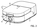
図1は、本発明が様々な実施形態で実施され得る、1つの特定の限定ではない実施形態に従う気道圧力支援システム2の概略図である。圧力支援システム2は、呼吸ガス流を供給するための装置4、この呼吸ガス流を伝えるための送出導管6、送出導管6からの呼吸ガス流を受け取る、及び患者の気道の周りに係合するように構成される患者インターフェース装置8、並びに患者インターフェース装置8を患者(P)の頭部に固定するためのヘッドギア10を含む。
FIG. 1 is a schematic diagram of an airway
装置4は、患者インターフェース装置8を介して患者Pの気道に送出される呼吸ガス流を生成するように構成されるガス流発生器12を含む。呼吸ガス流は、装置4の一部として設けられる加湿器14により加熱及び/又は加湿されてよい。ガス流発生器12及び加湿器14は、共通或いはメインのハウジング17に設けられてもよいし、又は何らかの適切な結合機構を介して互いに選択的に結合及び切り離され得る別個のハウジング18、20に設けられてもよい。
Device 4 includes a
ガス流発生器12は、限定ではないが、人工呼吸器、一定圧力支援装置(例えば持続陽圧呼吸装置又はCPAP装置)、可変圧力装置(例えば、ペンシルベニア州マリスビルのPhilips Respironics社により製造及び販売されるBiPAP(登録商標)、Bi-Flex(登録商標)又はC-Flex(登録商標)装置)及び自動滴定圧力支援装置を含む。送出導管6は、装置4から患者インターフェース装置8に呼吸ガス流を伝えるように構成される。送達導管6及び患者インターフェース装置8は、しばしば、総称して患者回路と呼ばれる。
The
BiPAP(登録商標)装置は、患者に供給される圧力が患者の呼吸サイクルと共に変化するバイレベル装置であるので、呼気中よりも吸気中の方がより高い圧力が送出される。自動滴定圧力支援システムは、例えば患者がいびきをしているか、又は無呼吸或いは低呼吸を経験しているかどうかのような、患者の状態と共に圧力が変化するシステムである。本発明は、ガス流発生器12が、患者の気道にガス流を送出するための、又は患者の気道におけるガスの圧力を上昇させるための、如何なる従来のシステムであり、これらは、上に要約された圧力支援システム及び非侵襲的な換気システムを含むと考えている。本明細書において、加圧したガス流が利用される例示的な実施形態で説明されていたとしても、本明細書に説明されるような本発明の実施形態が、他の一般的な加圧を行わない利用(例えば、限定ではないが、高流量療法の利用)にも容易に用いられ得ることも分かる。
BiPAP® devices are bilevel devices where the pressure delivered to the patient varies with the patient's breathing cycle, so a higher pressure is delivered during inspiration than during exhalation. Autotitrating pressure support systems are systems in which the pressure changes with the patient's condition, such as whether the patient is snoring or experiencing apnea or hypopnea. The present invention contemplates that the
図1に示される例示的な実施形態において、患者インターフェース装置8は、示される実施形態ではフルフェイスマスクである患者封止アセンブリ16を含む。しかしながら、他の種類の患者封止アセンブリ、例えば限定ではないが、鼻/口マスク、鼻クッション又は呼吸ガス流を患者の気道に送出することを容易にする他の如何なる構成も、本発明の範囲内にありつつ、患者封止アセンブリ16の代わりになり得ることが分かる。ヘッドギア10は、単に例示を目的に設けられ、如何なる適切なヘッドギア構成が本発明の範囲から逸脱することなく用いられ得ることも分かる。
In the exemplary embodiment shown in FIG. 1,
図2~図6を参照すると、本発明の1つの例示的な実施形態に従う例示的な装置4の様々な詳細図が示される。図1の概略図に関して上に述べたように、装置4は、ガス流発生器12(図4及び図5)及びメインのハウジング17内に位置決められる加湿器14を一般的に含む。ガス流発生器12は、(矢印Fで概略的に示される)呼吸ガス流を生成するように構成され、加湿器14は、ガス流発生器により生じた呼吸ガス流を加湿するように構成される。
2-6, various detailed views of an exemplary apparatus 4 according to one exemplary embodiment of the invention are shown. As mentioned above with respect to the schematic diagram of FIG. 1, device 4 generally includes a gas flow generator 12 (FIGS. 4 and 5) and a
図3~図6を参照すると、加湿器14は、その中に水Wを収容するように構成される水室30を含む。水室30は、頂部開口32を介して一般的にアクセス可能であり、必要に応じて、装置4のユーザにより、水Wが(例えば、水栓、水差し等により)この頂部開口32を介して水室30内に供給される。頂部開口32へのアクセスは、ハウジングの可動部分として動くように、ハウジング17に結合される内蓋40により制御される。従って、内蓋40は、内蓋40が水室30の頂部開口32を覆う第1の位置(図1、図5及び図6)と、内蓋40が水室30の頂部開口32を覆わない第2の位置(図3及び図4)との間で移動可能である。例示的な実施形態において、内蓋40は、回転軸44の周りを回転するように、ヒンジ機構42を介してハウジング17に回転可能に結合される。内蓋40は、例えば図2及び図6に一般的に示されるように、ハウジング17に結合される内蓋40の部分の概ね反対側に、上述した第1の位置にある内蓋40をハウジング17に確実に固定するのに使用するためのラッチ機構46を含んでよい。内蓋40に加え、ハウジング17に結合される外蓋50をさらに備えてもよく、この外蓋50は、外蓋50が内蓋40を覆う第1の位置(図2、図5及び図6)と、外蓋50が内蓋40を覆わない第2の位置(図3及び図4)との間で移動可能であるように設けられる。例示的な実施形態において、外蓋50は、回転軸44に対し略平行に配される第2の回転軸(番号なし)の周りを回転するようにハウジング17に回転可能に結合される。
Referring to FIGS. 3-6,
図4~図6を参照すると、ガス流発生器12により生じる呼吸ガス流Fは、ガス流発生器12から呼吸ガス流Fを受け取るように位置決め及び構成される(図4の62に概ね示される)第1の端部から、内蓋40上に配され、呼吸ガス流Fを加湿器14の水室30内に放出するように位置決め及び構成される反対側の第2の端部64まで延在する通路60を介して搬送される。示される例示的な実施形態において、通路60は、2つの部分、すなわちi)ハウジング17及び装置4の内部構成要素(番号なし)により概ね画定される第1の部分60A(図4)、並びにii)ヒンジ機構42及び内蓋40により概ね画定される第2の部分60B(図5及び図6)を一般的に含む。
4-6, a breathing gas flow F produced by
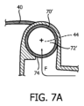
より詳細には、図4及び5に示されるように、ヒンジ機構42は、内蓋40が固定して結合される概ね円筒形の円筒部分70を含む。円筒部分70は、この円筒部分70の中心縦軸が回転軸44と一致するように、回転軸44の周りに配される。円筒部分70は、この円筒部分70(及び内蓋40)が回転軸44の周りを回転可能であるように、向かい合う端部70A、70Bに又はその周りでハウジング17に結合される。円筒部分70は、第1の端部70Aに又はその周りに配される入口74から、円筒部分70の第2の端部70Bに向かって延在し、回転軸44に概ね平行に配される側面出口76で終わるように、円筒部分70内に画定される中空部72を含む。図4及び図5に示される例において、入口74は、呼吸ガス流Fが回転軸44に沿った概ね軸方向に中空部72に入るように、第1の端部70Aの軸方向面(番号なし)に画定される。このような構成において、入口74は、円筒部分70の回転位置に関係なく、常に「開いて」いる。その一方、図7A及び7Bは、入口74が円筒部分70'の周囲面(番号なし)に画定される(及び軸方向面が閉じられている)もう1つの例示的な実施形態の断面図を示す。このような構成において、円筒部分70'(及び内蓋40)が、図7Aに示されるような「閉じた」位置に位置決められるとき、入口74は、呼吸ガス流Fを受け取るように位置決められる。しかしながら、円筒部分70'(及び内蓋40)が、(例えば、内蓋40及び円筒部分70'が方向Rに約90°回転することにより)図7Bに示されるような「開いた」位置に位置決められるとき、入口74は覆われ、従って、入口74を通り何れの方向にも流体(例えば、フローF、水)が通過することを防ぐ。ヒンジ機構42の構成は、本概念の範囲から逸脱することなく、一般的に反対である(すなわち、円筒部分70、70'がハウジング17に固定して結合され、入口74を介して内蓋40上の通路にフローを提供する)ことでもよいことが分かる。加えて、ガス流発生器12から、出口64と同じように内蓋40の一部に位置決められる出口までの通路を備える他の構成が、本概念の範囲から逸脱することなく、用いられてよいことも分かる。
More particularly, as shown in FIGS. 4 and 5,
再び図4~図6を参照すると、通路60の第2の部分60Bは、円筒部分70の側面出口76から、内蓋40の裏面(番号無し)に沿って延在し、反対側の第2の端部64で終わる概ね真っすぐな部分80をさらに含む。
Referring again to FIGS. 4-6, the
ここで図5及び図6を参照すると、水室30内の水Wに曝された(及びその水により加湿された)後、呼吸ガス流Fは、出口92で終わる出口通路90(図6)を介して水室30を出る。出口92は、ハウジング17の外側上に配され、図1と連動して上述した例えば送出導管6のような導管が、今加湿された呼吸ガス流Fを、患者の気道と係合する患者インターフェース装置にさらに伝えるために、出口92に簡単に結合されるように構成される。
Referring now to FIGS. 5 and 6, after being exposed to (and humidified by) the water W in the
上述したことから、本発明の実施形態は、加湿器の水室がCPAP装置に取り付けられている状態で、水がガス流発生装置に侵入する可能性を最小限に抑えながら、加湿器の水室が充填/再充填されることを可能にする構成を提供することが分かる。 From the foregoing, embodiments of the present invention provide a method for reducing the amount of water in a humidifier while minimizing the possibility of water entering the gas flow generator when the humidifier water chamber is attached to a CPAP device. It will be appreciated that an arrangement is provided which allows the chamber to be filled/refilled.
本発明は、最も実用的で好ましい実施形態であると現在考えられているものに基づいて、例示の目的に詳細に説明されていたとしても、そのような詳細は、単に例示が目的であること、並びに本発明は、開示される実施形態に限定されるのではなく、それどころか添付の特許請求の範囲の主旨及び範囲内にある修正案及び同等の構成を含むことが意図されることを理解されたい。例えば、本発明は、可能な限り、何れかの実施形態の1つ以上の特徴が他の何れかの実施形態の1つ以上の特徴と組み合わされ得ることを考えていると理解されるべきである。 Although the invention has been described in detail for purposes of illustration and based on what is presently believed to be the most practical and preferred embodiment, such details are for purposes of illustration only. , and it is to be understood that the invention is not limited to the disclosed embodiments, but rather is intended to include modifications and equivalent constructions within the spirit and scope of the appended claims. sea bream. For example, it should be understood that the invention contemplates that, to the extent possible, one or more features of any embodiment may be combined with one or more features of any other embodiment. be.
請求項において、括弧の間に置かれる如何なる参照記号もその請求項を限定するとは解釈されるべきではない。「有する」又は「含む」という言葉は、請求項に挙げられる以外の素子又はステップの存在を排除するものではない。幾つかの手段を列挙している装置の請求項において、これらの手段の幾つかは、ハードウェアの同一のアイテムにより具現化されてもよい。要素が複数あると述べていなくても、その要素が複数あることを排除しない。幾つかの手段を列挙している如何なる装置の請求項において、これらの手段の幾つかは、ハードウェアの1つの同じアイテムによって具現化されてもよい。幾つかの要素が互いに異なる従属請求項に挙げられているという単なる事実は、これらの要素が組み合わせて使用されることができないことを示していない。 In the claims, any reference signs placed between parentheses shall not be construed as limiting the claim. The word ``comprising'' or ``comprising'' does not exclude the presence of elements or steps other than those listed in a claim. In the device claim enumerating several means, several of these means may be embodied by one and the same item of hardware. Not stating that there is more than one element does not exclude that there is more than one of that element. In any device claim enumerating several means, several of these means may be embodied by one and the same item of hardware. The mere fact that certain elements are recited in mutually different dependent claims does not indicate that these elements cannot be used in combination.
Claims (10)
ハウジング、
前記ハウジング内に配され、前記呼吸ガス流を生成するように構成されるガス流発生器、
前記ハウジング内に配され、その中に水(W)を収容するように構成される水室を有する加湿器であり、前記水室は、当該水室に水を供給するための頂部開口を有する、加湿器、
蓋が前記水室の前記頂部開口を覆う第1の位置と、前記蓋が前記水室の前記頂部開口を覆わない第2の位置との間を前記蓋が移動可能であるように、前記ハウジングに結合される前記蓋、
前記ガス流発生器からの前記呼吸ガス流を受け取るように位置決め及び構成される第1の端部から、前記蓋の上に位置決められ、前記呼吸ガス流を前記水室内に放出するように構成される反対側の第2の端部まで延在する通路、並びに
前記ハウジング内に位置決められ、前記水室からの呼吸ガス流を前記ハウジングから外に運ぶように構成される出口
を有し、
前記蓋が回転軸の周りを回転可能であるように、前記蓋は、ヒンジ機構を介して前記ハウジングに回転可能に結合され、前記通路の一部は、前記ヒンジ機構により画定される、
装置。 A device for supplying a respiratory gas flow (F) to a patient, said device comprising:
housing,
a gas flow generator disposed within the housing and configured to generate the breathing gas flow;
A humidifier having a water chamber disposed within the housing and configured to contain water (W) therein, the water chamber having a top opening for supplying water to the water chamber. ,humidifier,
the housing, such that the lid is movable between a first position in which the lid covers the top opening of the water chamber and a second position in which the lid does not cover the top opening of the water chamber; said lid coupled to;
from a first end positioned and configured to receive the breathing gas flow from the gas flow generator and positioned on the lid and configured to discharge the breathing gas flow into the water chamber; a passageway extending to an opposite second end of the housing, and an outlet positioned within the housing and configured to convey a flow of breathing gas from the water chamber out of the housing;
the lid is rotatably coupled to the housing via a hinge mechanism such that the lid is rotatable about an axis of rotation, and a portion of the passageway is defined by the hinge mechanism;
Device.
患者に呼吸ガス流を供給するための装置であり、
ハウジング、
前記ハウジング内に配され、前記呼吸ガス流を生成するように構成されるガス流発生器、
前記ハウジング内に配され、その中に水を収容するように構成される水室を持つ加湿器であり、前記水室は、当該水室に水を供給するための頂部開口を持つ、加湿器、
蓋が前記水室の頂部開口を覆う第1の位置と、前記蓋が前記水室の頂部開口を覆わない第2の位置との間を前記蓋が移動可能であるように、前記ハウジングに結合される前記蓋、
前記ガス流発生器からの前記呼吸ガス流を受け取るように位置決め及び構成される第1の端部から、前記蓋の上に位置決められ、前記呼吸ガス流を前記水室内に放出するように構成される反対側の第2の端部まで延在する通路、並びに
前記ハウジング上に位置決められ、前記水室からの前記呼吸ガス流を前記ハウジングから外に運ぶように構成される出口
を有し、前記蓋が回転軸の周りを回転可能であるように、前記蓋は、ヒンジ機構を介して前記ハウジングに回転可能に結合され、前記通路の一部は、前記ヒンジ機構により画定される、装置、
前記装置の出口に結合される第1の端部及び反対側の第2の端部を持ち、前記呼吸ガス流を前記第1の端部から前記第2の端部に運ぶように構成される、送出導管、並びに
前記呼吸ガス流を前記患者の気道に供給するために、前記送出導管の前記第2の端部に結合される患者インターフェース装置
を有する気道圧力支援システム。 An airway pressure support system for use in providing a respiratory gas flow to a patient's airway, the system comprising:
A device for supplying a respiratory gas flow to a patient,
housing,
a gas flow generator disposed within the housing and configured to generate the breathing gas flow;
A humidifier having a water chamber disposed within the housing and configured to contain water therein, the water chamber having a top opening for supplying water to the water chamber. ,
The lid is coupled to the housing such that the lid is movable between a first position in which the lid covers a top opening of the water chamber and a second position in which the lid does not cover the top opening of the water chamber. the lid;
from a first end positioned and configured to receive the breathing gas flow from the gas flow generator and positioned on the lid and configured to discharge the breathing gas flow into the water chamber; a passageway extending to an opposite second end of the housing, and an outlet positioned on the housing and configured to convey the breathing gas flow from the water chamber out of the housing; the lid is rotatably coupled to the housing via a hinge mechanism such that the lid is rotatable about an axis of rotation, and a portion of the passageway is defined by the hinge mechanism;
a first end coupled to an outlet of the device and an opposite second end configured to convey the respiratory gas flow from the first end to the second end; , a delivery conduit, and a patient interface device coupled to the second end of the delivery conduit for delivering the respiratory gas flow to the patient's airway.
Applications Claiming Priority (3)
| Application Number | Priority Date | Filing Date | Title |
|---|---|---|---|
| US201862738376P | 2018-09-28 | 2018-09-28 | |
| US62/738,376 | 2018-09-28 | ||
| PCT/EP2019/075986 WO2020064906A1 (en) | 2018-09-28 | 2019-09-26 | Humidifier with ingress protection for use in cpap therapy |
Publications (3)
| Publication Number | Publication Date |
|---|---|
| JP2022502152A JP2022502152A (en) | 2022-01-11 |
| JPWO2020064906A5 JPWO2020064906A5 (en) | 2022-07-21 |
| JP7397860B2 true JP7397860B2 (en) | 2023-12-13 |
Family
ID=68104609
Family Applications (1)
| Application Number | Title | Priority Date | Filing Date |
|---|---|---|---|
| JP2021516780A Active JP7397860B2 (en) | 2018-09-28 | 2019-09-26 | Humidifier with protection against penetration for use in CPAP therapy |
Country Status (5)
| Country | Link |
|---|---|
| US (1) | US11484682B2 (en) |
| EP (1) | EP3856312A1 (en) |
| JP (1) | JP7397860B2 (en) |
| CN (1) | CN112770802B (en) |
| WO (1) | WO2020064906A1 (en) |
Families Citing this family (7)
| Publication number | Priority date | Publication date | Assignee | Title |
|---|---|---|---|---|
| EP4082594A1 (en) * | 2013-03-15 | 2022-11-02 | ResMed Pty Ltd | Water reservoir and respiratory pressure device |
| CN112546379A (en) * | 2018-10-26 | 2021-03-26 | 北京怡和嘉业医疗科技股份有限公司 | Respiratory ventilation apparatus |
| USD948055S1 (en) * | 2019-04-16 | 2022-04-05 | Perma Pure Llc | Humidifier cartridge for low-flow oxygen therapy |
| USD936833S1 (en) * | 2019-04-16 | 2021-11-23 | Perma Pure Llc | Humidifier for low-flow oxygen therapy |
| USD928962S1 (en) * | 2019-04-16 | 2021-08-24 | Perma Pure Llc | Humidifier base for low-flow oxygen therapy |
| WO2020212902A1 (en) * | 2019-04-17 | 2020-10-22 | ResMed Pty Ltd | Cpap system |
| JP7124970B2 (en) * | 2019-07-04 | 2022-08-24 | 株式会社村田製作所 | respiratory blower |
Citations (5)
| Publication number | Priority date | Publication date | Assignee | Title |
|---|---|---|---|---|
| US20130174843A1 (en) | 2011-12-22 | 2013-07-11 | Resmed Limited | Humidifiers for respiratory apparatus |
| US20140109907A1 (en) | 2008-02-01 | 2014-04-24 | Rajiv Doshi | Cpap interface and backup devices |
| US20140264975A1 (en) | 2013-03-15 | 2014-09-18 | Resmed Limited | Humidifier reservoir |
| JP2015515875A (en) | 2012-05-01 | 2015-06-04 | コーニンクレッカ フィリップス エヌ ヴェ | System and method for controlling flow in a respiratory support system during expiration |
| JP2018140193A (en) | 2011-09-13 | 2018-09-13 | レスメド・リミテッドResMed Limited | Apparatus for controlling gas washout of patient interface of respiratory treatment apparatus |
Family Cites Families (19)
| Publication number | Priority date | Publication date | Assignee | Title |
|---|---|---|---|---|
| US3667463A (en) * | 1969-11-14 | 1972-06-06 | David L Barnes | Method and apparatus for treatment of respiratory disease |
| US5645769A (en) * | 1994-06-17 | 1997-07-08 | Nippondenso Co., Ltd. | Humidified cool wind system for vehicles |
| US5511539A (en) | 1995-06-19 | 1996-04-30 | Lien; Su-Chu | Dose inhaler |
| DE10016005B4 (en) * | 2000-03-31 | 2007-11-22 | Map Medizin-Technologie Gmbh | Device for breathing gas humidification |
| CN1301761C (en) | 2001-02-16 | 2007-02-28 | 雷斯梅德有限公司 | Humidifier with structure to prevent backflow of liquid through humidifier inlet |
| NZ596207A (en) * | 2003-06-20 | 2013-05-31 | Resmed Ltd | Blower with one of lid and chassis made of metal and plastic composite |
| JP2005287596A (en) * | 2004-03-31 | 2005-10-20 | Teijin Pharma Ltd | Respiration gas feeder |
| DE102004052054A1 (en) * | 2004-10-26 | 2006-04-27 | Map Medizin-Technologie Gmbh | Device for administration of breathable room air and other components to make air pressure levels above the ambient pressure in a phased manner by conveyor system of first module and second module |
| US20070035044A1 (en) * | 2005-08-15 | 2007-02-15 | Paul Chiu | Humidifier having a night lamp function |
| WO2007024812A1 (en) * | 2005-08-23 | 2007-03-01 | Aerogen, Inc. | Self-sealing t-piece and valved t-piece |
| BRPI0617296A2 (en) * | 2005-10-21 | 2013-02-26 | Compumedics Ltd | pressurized gas delivery apparatus |
| WO2008042912A2 (en) * | 2006-10-02 | 2008-04-10 | Philip Morris Products S.A. | Continuous high pressure delivery system |
| US20080093750A1 (en) * | 2006-10-18 | 2008-04-24 | Zhijing Wang | Dual inlet water tank for a humidifier |
| US8453640B2 (en) * | 2008-11-12 | 2013-06-04 | Resmed Limited | Positive airway pressure device |
| US9737682B2 (en) | 2009-09-17 | 2017-08-22 | Resmed Limited | Humidification of respiratory gases |
| US8757154B2 (en) * | 2011-08-09 | 2014-06-24 | Carmen Schuller | Air purifier apparatus |
| EP4082594A1 (en) * | 2013-03-15 | 2022-11-02 | ResMed Pty Ltd | Water reservoir and respiratory pressure device |
| EP3013401B1 (en) * | 2013-06-28 | 2018-11-07 | Koninklijke Philips N.V. | Humidifier assembly and method of providing moisture to supplied gas in a pressure support system. |
| KR101685901B1 (en) * | 2016-07-15 | 2016-12-13 | 최연옥 | Portable air cleaner |
-
2019
- 2019-09-25 US US16/582,218 patent/US11484682B2/en active Active
- 2019-09-26 EP EP19779828.3A patent/EP3856312A1/en active Pending
- 2019-09-26 CN CN201980062583.1A patent/CN112770802B/en active Active
- 2019-09-26 JP JP2021516780A patent/JP7397860B2/en active Active
- 2019-09-26 WO PCT/EP2019/075986 patent/WO2020064906A1/en unknown
Patent Citations (5)
| Publication number | Priority date | Publication date | Assignee | Title |
|---|---|---|---|---|
| US20140109907A1 (en) | 2008-02-01 | 2014-04-24 | Rajiv Doshi | Cpap interface and backup devices |
| JP2018140193A (en) | 2011-09-13 | 2018-09-13 | レスメド・リミテッドResMed Limited | Apparatus for controlling gas washout of patient interface of respiratory treatment apparatus |
| US20130174843A1 (en) | 2011-12-22 | 2013-07-11 | Resmed Limited | Humidifiers for respiratory apparatus |
| JP2015515875A (en) | 2012-05-01 | 2015-06-04 | コーニンクレッカ フィリップス エヌ ヴェ | System and method for controlling flow in a respiratory support system during expiration |
| US20140264975A1 (en) | 2013-03-15 | 2014-09-18 | Resmed Limited | Humidifier reservoir |
Also Published As
| Publication number | Publication date |
|---|---|
| CN112770802B (en) | 2024-09-10 |
| CN112770802A (en) | 2021-05-07 |
| US20200101258A1 (en) | 2020-04-02 |
| EP3856312A1 (en) | 2021-08-04 |
| JP2022502152A (en) | 2022-01-11 |
| US11484682B2 (en) | 2022-11-01 |
| WO2020064906A1 (en) | 2020-04-02 |
Similar Documents
| Publication | Publication Date | Title |
|---|---|---|
| JP7397860B2 (en) | Humidifier with protection against penetration for use in CPAP therapy | |
| EP2575944B1 (en) | Automatic control of temperature in a patient circuit | |
| CA2556016C (en) | Sealing nasal cannula | |
| US8011369B2 (en) | Connector for a respiratory mask and a respiratory mask | |
| US20150040907A1 (en) | Valved breathing device providing adjustable expiration resistance for the treatment of sleep disordered breathing | |
| GB2530670A (en) | An interface | |
| US8205615B1 (en) | Self directing exhaust port assembly | |
| JP7471282B2 (en) | Humidifier with ingress protection for use in CPAP therapy | |
| JP6932202B2 (en) | Moisture relief conduits and systems | |
| JP2024110974A (en) | Ventilation system for patient interfaces | |
| CN116322851A (en) | Exhaust apparatus for patient interface device and patient interface including the same | |
| WO2013144740A1 (en) | Selectable exhaust port assembly | |
| CN111163825A (en) | Inflatable catheter and headgear including same | |
| JP7474739B2 (en) | Nose portion and patient interface device including said nose portion | |
| US12097326B2 (en) | Patient interface having a restrictor element for varying flow resistance through an exhalation port thereof | |
| JP7442510B2 (en) | A bendable substrate and a patient interface formed from the substrate. | |
| US11458268B2 (en) | Systems and methods for concurrent airway stabilization and pulmonary stretch receptor activation | |
| US20200001029A1 (en) | Compact fluid moving assembly and device employing same |
Legal Events
| Date | Code | Title | Description |
|---|---|---|---|
| A521 | Request for written amendment filed |
Free format text: JAPANESE INTERMEDIATE CODE: A523 Effective date: 20220712 |
|
| A621 | Written request for application examination |
Free format text: JAPANESE INTERMEDIATE CODE: A621 Effective date: 20220712 |
|
| A977 | Report on retrieval |
Free format text: JAPANESE INTERMEDIATE CODE: A971007 Effective date: 20230710 |
|
| A131 | Notification of reasons for refusal |
Free format text: JAPANESE INTERMEDIATE CODE: A131 Effective date: 20230718 |
|
| A521 | Request for written amendment filed |
Free format text: JAPANESE INTERMEDIATE CODE: A523 Effective date: 20231004 |
|
| TRDD | Decision of grant or rejection written | ||
| A01 | Written decision to grant a patent or to grant a registration (utility model) |
Free format text: JAPANESE INTERMEDIATE CODE: A01 Effective date: 20231124 |
|
| A61 | First payment of annual fees (during grant procedure) |
Free format text: JAPANESE INTERMEDIATE CODE: A61 Effective date: 20231201 |
|
| R150 | Certificate of patent or registration of utility model |
Ref document number: 7397860 Country of ref document: JP Free format text: JAPANESE INTERMEDIATE CODE: R150 |