JP7396796B2 - earphone device - Google Patents
earphone device Download PDFInfo
- Publication number
- JP7396796B2 JP7396796B2 JP2019011462A JP2019011462A JP7396796B2 JP 7396796 B2 JP7396796 B2 JP 7396796B2 JP 2019011462 A JP2019011462 A JP 2019011462A JP 2019011462 A JP2019011462 A JP 2019011462A JP 7396796 B2 JP7396796 B2 JP 7396796B2
- Authority
- JP
- Japan
- Prior art keywords
- earphone
- volume level
- earphones
- operation mode
- holder
- Prior art date
- Legal status (The legal status is an assumption and is not a legal conclusion. Google has not performed a legal analysis and makes no representation as to the accuracy of the status listed.)
- Active
Links
- 210000005069 ears Anatomy 0.000 claims description 43
- 238000001514 detection method Methods 0.000 claims description 12
- 238000004891 communication Methods 0.000 description 10
- 238000010586 diagram Methods 0.000 description 5
- 230000002093 peripheral effect Effects 0.000 description 5
- 238000000034 method Methods 0.000 description 3
- XEEYBQQBJWHFJM-UHFFFAOYSA-N Iron Chemical compound [Fe] XEEYBQQBJWHFJM-UHFFFAOYSA-N 0.000 description 2
- 230000005540 biological transmission Effects 0.000 description 1
- 229910052742 iron Inorganic materials 0.000 description 1
- 238000012986 modification Methods 0.000 description 1
- 230000004048 modification Effects 0.000 description 1
Images


Classifications
-
- H—ELECTRICITY
- H04—ELECTRIC COMMUNICATION TECHNIQUE
- H04R—LOUDSPEAKERS, MICROPHONES, GRAMOPHONE PICK-UPS OR LIKE ACOUSTIC ELECTROMECHANICAL TRANSDUCERS; DEAF-AID SETS; PUBLIC ADDRESS SYSTEMS
- H04R1/00—Details of transducers, loudspeakers or microphones
- H04R1/10—Earpieces; Attachments therefor ; Earphones; Monophonic headphones
- H04R1/1041—Mechanical or electronic switches, or control elements
-
- H—ELECTRICITY
- H04—ELECTRIC COMMUNICATION TECHNIQUE
- H04R—LOUDSPEAKERS, MICROPHONES, GRAMOPHONE PICK-UPS OR LIKE ACOUSTIC ELECTROMECHANICAL TRANSDUCERS; DEAF-AID SETS; PUBLIC ADDRESS SYSTEMS
- H04R5/00—Stereophonic arrangements
- H04R5/033—Headphones for stereophonic communication
- H04R5/0335—Earpiece support, e.g. headbands or neckrests
-
- G—PHYSICS
- G10—MUSICAL INSTRUMENTS; ACOUSTICS
- G10L—SPEECH ANALYSIS OR SYNTHESIS; SPEECH RECOGNITION; SPEECH OR VOICE PROCESSING; SPEECH OR AUDIO CODING OR DECODING
- G10L15/00—Speech recognition
- G10L15/22—Procedures used during a speech recognition process, e.g. man-machine dialogue
-
- H—ELECTRICITY
- H04—ELECTRIC COMMUNICATION TECHNIQUE
- H04R—LOUDSPEAKERS, MICROPHONES, GRAMOPHONE PICK-UPS OR LIKE ACOUSTIC ELECTROMECHANICAL TRANSDUCERS; DEAF-AID SETS; PUBLIC ADDRESS SYSTEMS
- H04R1/00—Details of transducers, loudspeakers or microphones
- H04R1/08—Mouthpieces; Microphones; Attachments therefor
-
- H—ELECTRICITY
- H04—ELECTRIC COMMUNICATION TECHNIQUE
- H04R—LOUDSPEAKERS, MICROPHONES, GRAMOPHONE PICK-UPS OR LIKE ACOUSTIC ELECTROMECHANICAL TRANSDUCERS; DEAF-AID SETS; PUBLIC ADDRESS SYSTEMS
- H04R1/00—Details of transducers, loudspeakers or microphones
- H04R1/10—Earpieces; Attachments therefor ; Earphones; Monophonic headphones
- H04R1/1016—Earpieces of the intra-aural type
-
- H—ELECTRICITY
- H04—ELECTRIC COMMUNICATION TECHNIQUE
- H04R—LOUDSPEAKERS, MICROPHONES, GRAMOPHONE PICK-UPS OR LIKE ACOUSTIC ELECTROMECHANICAL TRANSDUCERS; DEAF-AID SETS; PUBLIC ADDRESS SYSTEMS
- H04R1/00—Details of transducers, loudspeakers or microphones
- H04R1/10—Earpieces; Attachments therefor ; Earphones; Monophonic headphones
- H04R1/105—Earpiece supports, e.g. ear hooks
-
- H—ELECTRICITY
- H04—ELECTRIC COMMUNICATION TECHNIQUE
- H04R—LOUDSPEAKERS, MICROPHONES, GRAMOPHONE PICK-UPS OR LIKE ACOUSTIC ELECTROMECHANICAL TRANSDUCERS; DEAF-AID SETS; PUBLIC ADDRESS SYSTEMS
- H04R1/00—Details of transducers, loudspeakers or microphones
- H04R1/10—Earpieces; Attachments therefor ; Earphones; Monophonic headphones
- H04R1/1058—Manufacture or assembly
- H04R1/1066—Constructional aspects of the interconnection between earpiece and earpiece support
-
- G—PHYSICS
- G10—MUSICAL INSTRUMENTS; ACOUSTICS
- G10L—SPEECH ANALYSIS OR SYNTHESIS; SPEECH RECOGNITION; SPEECH OR VOICE PROCESSING; SPEECH OR AUDIO CODING OR DECODING
- G10L15/00—Speech recognition
- G10L15/22—Procedures used during a speech recognition process, e.g. man-machine dialogue
- G10L2015/223—Execution procedure of a spoken command
-
- H—ELECTRICITY
- H04—ELECTRIC COMMUNICATION TECHNIQUE
- H04R—LOUDSPEAKERS, MICROPHONES, GRAMOPHONE PICK-UPS OR LIKE ACOUSTIC ELECTROMECHANICAL TRANSDUCERS; DEAF-AID SETS; PUBLIC ADDRESS SYSTEMS
- H04R2420/00—Details of connection covered by H04R, not provided for in its groups
- H04R2420/07—Applications of wireless loudspeakers or wireless microphones
-
- H—ELECTRICITY
- H04—ELECTRIC COMMUNICATION TECHNIQUE
- H04R—LOUDSPEAKERS, MICROPHONES, GRAMOPHONE PICK-UPS OR LIKE ACOUSTIC ELECTROMECHANICAL TRANSDUCERS; DEAF-AID SETS; PUBLIC ADDRESS SYSTEMS
- H04R2430/00—Signal processing covered by H04R, not provided for in its groups
- H04R2430/01—Aspects of volume control, not necessarily automatic, in sound systems
-
- H—ELECTRICITY
- H04—ELECTRIC COMMUNICATION TECHNIQUE
- H04R—LOUDSPEAKERS, MICROPHONES, GRAMOPHONE PICK-UPS OR LIKE ACOUSTIC ELECTROMECHANICAL TRANSDUCERS; DEAF-AID SETS; PUBLIC ADDRESS SYSTEMS
- H04R29/00—Monitoring arrangements; Testing arrangements
- H04R29/004—Monitoring arrangements; Testing arrangements for microphones
Description
本発明は、イヤホン装置に関し、特にネックバンド方式のイヤホン装置に関する。 The present invention relates to an earphone device, and particularly to a neckband type earphone device.
携帯音楽プレーヤ等からBluetooth(登録商標)等の近距離無線通信によりワイヤレス送信されたオーディオデータを受信してイヤホンで聴取するイヤホン装置が普及している(例えば特許文献1)。この種のイヤホン装置として、イヤホンがケーブル接続されたネックバンドを備え、このネックバンドを聴取者の首にかけて使用する、いわゆるネックバンド方式のイヤホン装置が知られている。また、この種のイヤホン装置には、マイクを備え、オーディオデータの聴取のみならず、スマートホン等の送受話器として機能するものもある。 2. Description of the Related Art Earphone devices that receive audio data wirelessly transmitted from a portable music player or the like by short-range wireless communication such as Bluetooth (registered trademark) and listen to it with earphones have become widespread (for example, Patent Document 1). As this type of earphone device, a so-called neckband-type earphone device is known, which includes a neckband to which earphones are connected with a cable, and is worn around the listener's neck. Furthermore, some earphone devices of this type are equipped with a microphone and function not only for listening to audio data but also as a handset for a smart phone or the like.
ところで、イヤホン装置は、イヤホンを耳に装着するものであり、聴取者は、イヤホン装置を長時間使用していると、耳が痛くなってイヤホンを耳から外したくなる場合がある。ここで、イヤホンの出力音量レベルは、イヤホンが耳に装着されていることを前提としているため、イヤホンを耳から外した状態では、イヤホンの出力音量レベルが小さすぎて、オーディオデータを聴取できない。このため、聴取者は、イヤホンを耳から外した状態においてもオーディオデータを聴取したい場合には、イヤホン装置あるいは携帯音楽プレーヤ等の音量ボリュームを操作して、イヤホンの出力音量レベルを大きくする必要がある。 By the way, an earphone device is a device that is worn in the ear, and when a listener uses the earphone device for a long time, the listener may feel pain in the ear and want to remove the earphone from the ear. Here, the output volume level of the earphones is based on the assumption that the earphones are worn in the ears, so when the earphones are removed from the ears, the output volume level of the earphones is too low to listen to audio data. Therefore, if a listener wants to listen to audio data even when the earphones are removed from the ear, the listener must increase the output volume level of the earphones by controlling the volume of the earphone device or portable music player. be.
一方、イヤホンを耳から外した状態においてオーディオデータを聴取できるようにした場合、イヤホンの出力音量レベルが大きすぎて、イヤホンを耳に装着できない。したがって、聴取者は、イヤホンを耳に装着してオーディオデータを聴取したい場合には、イヤホン装置あるいは携帯音楽プレーヤ等の音量ボリュームを操作して、イヤホンの出力音量レベルを小さくする必要がある。 On the other hand, if it is possible to listen to audio data while the earphones are removed from the ears, the output volume level of the earphones is too high to allow the earphones to be worn in the ears. Therefore, when a listener wants to listen to audio data by wearing earphones in the ear, the listener needs to operate the volume of the earphone device, portable music player, etc. to reduce the output volume level of the earphones.
このように、オーディオデータを聴取するためには、イヤホンの装着状態に応じて、イヤホン装置あるいは携帯音楽プレーヤ等の音量ボリュームを操作して、イヤホンの出力音量レベルを調節する必要があり煩わしい。 As described above, in order to listen to audio data, it is necessary to adjust the output volume level of the earphones by operating the volume of the earphone device, portable music player, etc., depending on the wearing state of the earphones, which is cumbersome.
本発明は上記事情に鑑みてなされたものであり、その目的は、イヤホンの装着状態にかかわらず、オーディオデータを良好に聴取することができるイヤホン装置を提供することにある。 The present invention has been made in view of the above circumstances, and an object of the present invention is to provide an earphone device that allows audio data to be listened to satisfactorily regardless of how the earphones are worn.
上記課題を解決するために、本発明のイヤホン装置では、動作モードとして、イヤホンを耳に装着した状態を想定した音量レベルでオーディオデータをイヤホンから出力する通常モード、およびイヤホンを耳から外した状態を想定した、通常モードより大きな音量レベルでオーディオデータをイヤホンから出力するスピーカモードを準備し、通常モードおよびスピーカモード間で動作モードを切り替えられるようにした。 In order to solve the above problems, the earphone device of the present invention has two operation modes: a normal mode in which audio data is output from the earphone at a volume level assuming the state in which the earphone is attached to the ear, and a state in which the earphone is removed from the ear. We have prepared a speaker mode that outputs audio data from the earphones at a higher volume level than the normal mode, and made it possible to switch the operating mode between the normal mode and the speaker mode.
ここで、イヤホンの装着状態を判断し、判断した装着状態に応じて動作モードを切り替えてもよい。あるいは、聴取者の音声コマンドを認識することにより動作モードを切り替えてもよい。 Here, the wearing state of the earphones may be determined, and the operation mode may be switched according to the determined wearing state. Alternatively, the operating mode may be switched by recognizing a listener's voice command.
例えば、本発明のイヤホン装置は、
オーディオデータをイヤホンから出力するイヤホン装置であって、
前記イヤホンから出力する音量レベルを制御する音量レベル制御手段と、
前記音量レベル制御手段の動作モードを、前記イヤホンが耳に装着された状態における聴取に対応する音量レベルで前記オーディオデータを前記イヤホンから出力する通常モード、および前記イヤホンが耳から外された状態における聴取に対応する、前記通常モードよりも大きな音量レベルで、前記オーディオデータを前記イヤホンから出力するスピーカモードのいずれかに切り替える動作モード切替手段と、
前記イヤホンにケーブル接続され、首にかけて使用するネックバンドと、
前記イヤホンの装着状態を判断する装着状態判断手段と、
マイクと、
前記マイクへの入力音量レベルを検出する音量レベル検出手段と、を備え、
前記ネックバンドは、
前記イヤホンを着脱自在に保持するホルダを有し、
前記ホルダは、
前記ネックバンドを首にかけた場合に、前記イヤホンの音声出力方向が耳に向かって上向きとなるように前記イヤホンを保持し、
前記装着状態判断手段は、
前記音量レベル検出手段によって検出された入力音量レベルが所定値未満の場合に前記イヤホンを耳に装着した状態であると判断し、前記所定値以上の場合に前記イヤホンを耳から外した状態であると判断し、
前記動作モード切替手段は、
前記装着状態判断手段により判断された前記イヤホンの装着状態に基づいて、前記音量レベル制御手段の動作モードを切り替えるとともに、前記音量レベル制御手段の動作モードを前記スピーカモードから前記通常モードに切り替えた場合、前記装着状態判断手段の判断結果にかかわらず、所定時間を経過するまで、前記音量レベル制御手段の動作モードを前記通常モードに固定する。
また、本発明の他の態様のイヤホン装置は、
オーディオデータをイヤホンから出力するイヤホン装置であって、
前記イヤホンから出力する音量レベルを制御する音量レベル制御手段と、
前記音量レベル制御手段の動作モードを、前記イヤホンを耳に装着した状態における聴取に対応する音量レベルで前記オーディオデータを前記イヤホンから出力する通常モード、および前記イヤホンを耳から外した状態における聴取に対応する、前記通常モードよりも大きな音量レベルで、前記オーディオデータを前記イヤホンから出力するスピーカモードのいずれかに切り替える動作モード切替手段と、
前記イヤホンの装着状態を判断する装着状態判断手段と、
マイクと、
前記マイクへの入力音量レベルを検出する音量レベル検出手段と、を備え、
前記動作モード切替手段は、
前記装着状態判断手段により判断された前記イヤホンの装着状態に基づいて、前記音量レベル制御手段の動作モードを切り替え、
前記装着状態判断手段は、
前記音量レベル検出手段によって検出された入力音量レベルが所定値未満の場合に前記イヤホンを耳に装着した状態であると判断し、前記所定値以上の場合に前記イヤホンを耳から外した状態であると判断し、
前記動作モード切替手段は、
前記音量レベル制御手段の動作モードを前記通常モードに切り替えた場合、前記装着状態判断手段の判断結果にかかわらず、所定時間を経過するまで、前記音量レベル制御手段の動作モードを前記通常モードに固定する。
For example, the earphone device of the present invention includes:
An earphone device that outputs audio data from the earphone,
Volume level control means for controlling the volume level output from the earphone;
The operation mode of the volume level control means is set to a normal mode in which the audio data is output from the earphone at a volume level corresponding to listening with the earphone attached to the ear, and a normal mode in which the audio data is output from the earphone at a volume level corresponding to listening with the earphone attached to the ear. operation mode switching means for switching to one of speaker modes for outputting the audio data from the earphones at a volume level higher than the normal mode, which corresponds to listening;
a neckband connected to the earphone by a cable and worn around the neck;
A wearing state determining means for determining a wearing state of the earphone;
Mike and
Volume level detection means for detecting the input volume level to the microphone,
The neckband is
a holder for detachably holding the earphone;
The holder is
Holding the earphones so that the audio output direction of the earphones is directed upward toward the ears when the neckband is worn around the neck;
The wearing state determining means includes:
If the input volume level detected by the volume level detecting means is less than a predetermined value, it is determined that the earphones are worn in the ears, and if the input volume level is equal to or higher than the predetermined value, the earphones are removed from the ears. I decided that
The operation mode switching means includes:
The operation mode of the volume level control means is switched based on the wearing state of the earphone determined by the wearing state determining means, and the operation mode of the volume level control means is switched from the speaker mode to the normal mode. , the operation mode of the volume level control means is fixed to the normal mode until a predetermined period of time has elapsed, regardless of the judgment result of the wearing state judgment means .
Further, an earphone device according to another aspect of the present invention includes:
An earphone device that outputs audio data from the earphone,
Volume level control means for controlling the volume level output from the earphone;
The operation mode of the volume level control means is set to a normal mode in which the audio data is output from the earphone at a volume level corresponding to listening with the earphone attached to the ear, and a normal mode for listening with the earphone removed from the ear. corresponding operation mode switching means for switching to one of the speaker modes for outputting the audio data from the earphones at a volume level greater than the normal mode;
A wearing state determining means for determining a wearing state of the earphone;
Mike and
Volume level detection means for detecting the input volume level to the microphone,
The operation mode switching means includes:
switching the operation mode of the volume level control means based on the wearing state of the earphone determined by the wearing state determining means;
The wearing state determining means includes:
If the input volume level detected by the volume level detecting means is less than a predetermined value, it is determined that the earphones are worn in the ears, and if the input volume level is equal to or higher than the predetermined value, the earphones are removed from the ears. I decided that
The operation mode switching means includes:
When the operation mode of the volume level control means is switched to the normal mode, the operation mode of the volume level control means is fixed to the normal mode until a predetermined time elapses, regardless of the judgment result of the wearing state judgment means. do.
本発明では、動作モードを、イヤホンが耳に装着された状態における聴取に対応する音量レベルでオーディオデータをイヤホンから出力する通常モード、およびイヤホンが耳から外された状態における聴取に対応する、通常モードより大きな音量レベルでオーディオデータをイヤホンから出力するスピーカモードのいずれかに切り替えられるようにしている。このため、聴取者は、イヤホンの装着状態に応じて音量ボリュームを操作して、イヤホンの出力音量レベルを調節する必要がない。したがって、本発明によれば、イヤホンの装着状態にかかわらず、オーディオデータを良好に聴取することができる。 In the present invention, the operating mode is set to a normal mode in which audio data is output from the earphone at a volume level corresponding to listening with the earphone in the ear, and a normal mode corresponding to listening with the earphone removed from the ear. It is possible to switch to one of the speaker modes that outputs audio data from the earphones at a higher volume level than the mode. Therefore, the listener does not need to adjust the output volume level of the earphones by operating the volume according to the wearing state of the earphones. Therefore, according to the present invention, audio data can be listened to satisfactorily regardless of how the earphones are worn.
以下、本発明の一実施の形態について、図面を参照して説明する。 DESCRIPTION OF THE PREFERRED EMBODIMENTS An embodiment of the present invention will be described below with reference to the drawings.
図1は、本実施の形態に係るイヤホン装置1の外観図である。図2(A)は、図1に示すイヤホン装置1のA部拡大図であり、図2(B)は、図1に示すイヤホン装置1のB部拡大図である。
FIG. 1 is an external view of an
図示するように、本実施の形態に係るイヤホン装置1は、ネックバンド方式のイヤホン装置であり、右耳用のイヤホン2aと、左耳用のイヤホン2bと、イヤホン2a、2bにケーブル接続されたU字形状のネックバンド3と、を備えている。このイヤホン装置1は、ネックバンド3が聴取者の首にかけられた状態で使用され、携帯音楽プレーヤ、スマートホン等からBluetooth(登録商標)等の近距離無線通信によりワイヤレス送信されたオーディオデータを受信してイヤホン2a、2bから出力する。
As shown in the figure, the
ネックバンド3を首にかけた聴取者から見て右側に位置する、ネックバンド3の先端部31aの外面32には、右耳用のイヤホン2aの被保持部20aを着脱自在に保持するホルダ(以下、右側のホルダとも呼ぶ)30aが設けられている。また、この聴取者から見て左側に位置する、ネックバンド3の先端部31bの外面32には、左耳用のイヤホン2bの被保持部20bを着脱自在に保持するホルダ(以下、左側のホルダとも呼ぶ)30bが設けられている。
On the
右側のホルダ30aは、突起300を例えば内周面に有する円柱状の凹部であり、その底面301には磁石302が取り付けられている(図2(A)参照)。一方、右耳用のイヤホン2aの被保持部20aは、右側のホルダ30aの突起300と係合する切欠き200を例えば外周面に有する、右側のホルダ30aに挿入可能な円柱状の凸部であり、その頂面201には、右側のホルダ30aの磁石302と逆極性の磁石202が取り付けられている(図2(B)参照)。
The
図示していないが、同様に、左側のホルダ30bは、突起300を内周面に有する円柱状の凹部であり、その底面301には磁石302が取り付けられている。一方、左耳用のイヤホン2bの被保持部20bは、左側のホルダ30bの突起300と係合する切欠き200を外周面に有する、左側のホルダ30bに挿入可能な円柱状の凸部であり、その頂面201には、左側のホルダ30bの磁石302と逆極性の磁石202が取り付けられている。ここで、右側のホルダ30aおよび左側のホルダ30bの磁石302の極性(右耳用のイヤホン2aの被保持部20aおよび左耳用のイヤホン2bの被保持部20bの磁石202の極性)は、互いに逆極性となるように設定されている。
Although not shown, the
被保持部20aの切欠き200を右側のホルダ30aの突起300に係合させつつ、被保持部20aを右側のホルダ30aに挿入することにより、被保持部20aの磁石202と右側のホルダ30aの磁石302との間で磁力による引力が発生し、被保持部20aが右側のホルダ30aに装着される。このとき、被保持部20aの切欠き200がホルダ30aの突起300と係合していることにより、図3に示すように、右耳用のイヤホン2aは、イヤーパッド203から出力される音声が聴取者の右耳に効率的に向かうように(音声出力方向Vaが聴取者の右耳に向かって上向きになるように)、イヤーパッド203を上方に向けた姿勢で固定される。
By inserting the held
同様に、被保持部20bの切欠き200を左側のホルダ30bの突起300に係合させつつ、被保持部20bを左側のホルダ30bに挿入することにより、被保持部20bの磁石202と左側のホルダ30bの磁石302との間で磁力による引力が発生し、被保持部20bが左側のホルダ30bに装着される。このとき、被保持部20bの切欠き200がホルダ30bの突起300と係合していることにより、図3に示すように、左耳用のイヤホン2bは、イヤーパッド203から出力される音声が聴取者の左耳に効率的に向かうように(音声出力方向Vbが聴取者の左耳に向かって上向きになるように)、イヤーパッド203を上方に向けた姿勢で固定される。
Similarly, by inserting the held
なお、右側のホルダ30aおよび左側のホルダ30bの磁石302の極性(右耳用のイヤホン2aの被保持部20aおよび左耳用のイヤホン2bの被保持部20bの磁石202の極性)は、互いに逆極性となるように設定されている。右耳用のイヤホン2aの被保持部20aを左側のホルダ30bに挿入すると、被保持部20aの磁石202とホルダ30bの磁石302との間で磁力による斥力が発生する。このため、右耳用のイヤホン2aの被保持部20aは左側のホルダ30bに装着されない。同様に、左耳用のイヤホン2bの被保持部20bを右側のホルダ30aに挿入すると、被保持部20bの磁石202とホルダ30aの磁石302との間で磁力による斥力が発生する。このため、左耳用のイヤホン2bの被保持部20bは右側のホルダ30aに装着されない。これにより、右側のホルダ30aへの左耳用のイヤホン2bの誤装着および左側のホルダ30bへの右耳用のイヤホン2aの誤装着を防止できる。
Note that the polarities of the
また、ネックバンド3には、本実施の形態に係るイヤホン装置1にワイヤレス接続された携帯音楽プレーヤ、スマートホン等に対する各種操作を聴取者から受け付けるための操作部33、およびマイク34が設けられている。
The
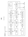
図4は、ネックバンド3の概略機能構成図である。
FIG. 4 is a schematic functional configuration diagram of the
図示するように、ネックバンド3は、上述のホルダ30a、30b、操作部33、およびマイク34に加えて、近距離無線通信部35と、イヤホン接続部36と、音量レベル検出部37と、装着状態判断部38と、音量レベル制御部39と、音響特性制御部40と、動作モード切替部41と、主制御部42と、を備えている。
As shown in the figure, the
近距離無線通信部35は、Bluetooth(登録商標)等の近距離無線通信により携帯音楽プレーヤ、スマートホン等と接続するためのインターフェースである。
The short-range
イヤホン接続部36は、ケーブルを介して各耳用のイヤホン2a、2bと接続するためのインターフェースである。
The
音量レベル検出部37は、マイク34への入力音量レベルを検出する。
The volume
装着状態判断部38は、音量レベル検出部37で検出されたマイク34への入力音量レベルに基づいて、各耳用のイヤホン2a、2bの装着状態を判断する。各耳用のイヤホン2a、2bのスピーカ(不図示)がイヤーパッド203で囲まれているため、各耳用のイヤホン2a、2bのイヤーパッド203がそれぞれ対応する耳穴に挿入されて、左右の耳にそれぞれイヤホン2a、2bが装着されている状態では、マイク34で検出されるイヤホン2a、2bの出力音声の音量レベルは極めて小さい。これに対して、左右の耳からそれぞれイヤホン2a、2bが外されている状態では、マイク34で検出される各耳用のイヤホン2a、2bの出力音声の音量レベルは、左右の耳にイヤホン2a、2bが装着されている状態に比べて大きくなる。そこで、装着状態判断部38は、音量レベル検出部37で検出されたマイク34への入力音量レベルが所定の閾値T(例えば5db)未満ならば、イヤホン2a、2bが左右の耳に装着された状態であると判断し、所定の閾値T以上ならば、イヤホン2a、2bが左右の耳から外された状態であると判断する。
The wearing
音量レベル制御部39は、近距離無線通信部35を介して携帯音楽プレーヤ、スマートホン等より受信したオーディオデータの音量レベルを制御する。
The volume
音響特性制御部40は、近距離無線通信部35を介して携帯音楽プレーヤ、スマートホン等より受信したオーディオデータの音響特性(周波数特性)を制御する。
The acoustic characteristics control
動作モード切替部41は、装着状態判断部38で判断されたイヤホン2a、2bの装着状態に基づいて、音量レベル制御部39および音響特性制御部40の動作モードを切り替える。具体的には、イヤホン2a、2bが左右の耳に装着されている状態の場合、音量レベル制御部39の動作モードを、イヤホン2a、2bが左右の耳に装着されている状態における聴取を想定して定めた音量レベル(例えば30db)でオーディオデータを各耳用のイヤホン2a、2bから出力する通常モードに設定するとともに、音響特性制御部40の動作モードを、イヤホン2a、2bを左右の耳に装着した状態における聴取を想定して定めた音響特性でオーディオデータをイヤホン2a、2bから出力する通常モードに設定する。一方、イヤホン2a、2bが左右の耳から外れている状態の場合、音量レベル制御部39の動作モードを、イヤホン2a、2bを左右の耳から外した状態における聴取を想定して、通常モードよりも大きな値に定めた音量レベル(例えば50db)でオーディオデータをイヤホン2a、2bから出力するスピーカモードに設定するとともに、音響特性制御部40の動作モードを、聴取者がイヤホン2a、2bを左右の耳から外した状態における聴取を想定して、通常モードよりも低周波数帯域が強調されるように定めた音響特性でオーディオデータを各耳用のイヤホン2a、2bから出力するスピーカモードに設定する。
The operation
主制御部42は、ネックバンド3の各部を統括的に制御する。例えば、操作部33を介して聴取者より受け付けた動作モードの設定操作に従い、音量レベル制御部39および音響特性制御部40の通常モード、スピーカモードにおける音量レベルおよび音響特性を、動作モード切替部41に設定する。また、操作部33を介して聴取者より受け付けた、携帯音楽プレーヤ、スマートホン等に対する再生操作等の操作内容を、近距離無線通信部35を介して携帯音楽プレーヤ、スマートホン等に送信する。
The
図5は、ネックバンド3の動作モード切替処理を説明するためのフロー図である。
FIG. 5 is a flow diagram for explaining the operation mode switching process of the
このフローは、操作部33を介して聴取者より受け付けたオーディオデータの再生操作に従い、主制御部42が近距離無線通信部35を介して携帯音楽プレーヤ、スマートホン等にオーディオデータの再生指示を送信することにより開始し、携帯音楽プレーヤ、スマートホン等によるオーディオデータの再生が終了することにより終了する。
In this flow, the
まず、動作モード切替部41は、音量レベル制御部39および音響特性制御部40の動作モードを通常モードに設定する(S10)。また、音量レベル検出部37は、マイク34の入力音量レベルの検出を開始する(S11)。
First, the operation
つぎに、装着状態判断部38は、音量レベル検出部37で検出された入力音量レベルを監視し、この入力音量レベルが所定の閾値T以上であるか否かを判断する(S12)。そして、この入力音量レベルが所定の閾値T以上であるならば(S12でYES)、イヤホン2a、2bが左右の耳から外されている状態であると判断し、この判断結果を動作モード切替部41に通知する。
Next, the wearing
これを受けて、動作モード切替部41は、音量レベル制御部39および音響特性制御部40の動作モードをスピーカモードに切り替える(S13)。この際、音量レベル制御部39は、オーディオデータの音量レベルをいきなり通常モードからスピーカモードに切り替えるのではなく、徐々に音量レベルを大きくしてスピーカモードに切り替えることが好ましい。
In response to this, the operation
その後、装着状態判断部38は、音量レベル検出部37で検出された入力音量レベルを監視し、所定の閾値T未満であるか否かをチェックする(S14)。そして、聴取者がイヤホン2a、2bのオーディオ出力用開口部(イヤーパッド203の先端部分)を指で塞ぐなどして、左右の耳へのイヤホン2a、2bの装着準備を開始して、これにより入力音量レベルが所定の閾値T未満となった場合(S14でYES)、装着状態判断部38は、イヤホン2a、2bが左右の耳に装着された状態であると判断し、この判断結果を動作モード切替部41に通知する。
Thereafter, the wearing
これを受けて、動作モード切替部41は、音量レベル制御部39および音響特性制御部40の動作モードを通常モードに切り替える(S15)。そして、所定時間(例えば10秒)の間、入力音量レベルにかかわらず通常モードに固定して(S16)、聴取者がイヤホン2a、2bを左右の耳に装着し終わるのを待つ。それから、S12に戻る。
In response to this, the operation
以上、本発明の一実施の形態について説明した。 An embodiment of the present invention has been described above.
本実施の形態では、音量レベル制御部39の動作モードを、イヤホン2a、2bが聴取者の耳に装着された状態における聴取を想定して定めた音量レベルでオーディオデータをイヤホン2a、2bから出力する通常モード、およびイヤホン2a、2bが聴取者の耳から外した状態における聴取を想定して、通常モードより大きな値に定めた音量レベルでオーディオデータをイヤホン2a、2bから出力するスピーカモードのいずれかに切り替えられるようにしている。このため、聴取者は、イヤホン2a、2bの装着状態に応じて音量ボリュームを操作して、イヤホン2a、2bの出力音量レベルを調節する必要がない。したがって、本実施の形態によれば、イヤホン2a、2bの装着状態にかかわらず、オーディオデータを良好に聴取することができる。
In the present embodiment, the operation mode of the volume
また、本実施の形態では、イヤホン2a、2bの装着状態を判断し、その判断結果に基づいて、音量レベル制御部39の動作モードを通常モードおよびスピーカモードのいずれかに切り替えているので、聴取者は、イヤホン装置1に特別な指示を入力することなく、動作モードを切り替えることができる。したがって、本実施の形態によれば、イヤホン装置1の使い勝手を向上させることができる。
Furthermore, in this embodiment, the wearing state of the
また、本実施の形態では、マイク34の入力音量レベルが所定の閾値T未満の場合に聴取者がイヤホン2a、2bを耳に装着した状態であると判断し、所定の閾値T以上の場合に聴取者がイヤホン2a、2bを耳から外した状態であると判断している。このため、オーディオデータの聴取のみならず、スマートホン等の送受話器として機能するイヤホン装置1においては、送受話器に使用するマイクをマイク34として併用することにより、コストの増加を抑制することができる。
Furthermore, in the present embodiment, it is determined that the listener is wearing the
また、本実施の形態では、イヤホン2a、2bにケーブル接続され、首にかけて使用するネックバンド3に、イヤホン2a、2bを着脱自在に保持するホルダ30a、30bを設けている。そして、聴取者がネックバンド3を首にかけた場合にイヤホン2a、2bの音声出力方向Va、Vbが上方(具体的には、聴取者の耳に向かう方向)となるように、ホルダ30a、30bにイヤホン2a、2bを保持させている。このため、スピーカモードの際に、イヤホン2a、2bから出力されたオーディオを聴取者の耳に効率よく届けることができる。したがって、本実施の形態によれば、スピーカモードの際に、オーディオデータをより良好に聴取することができる。
Further, in this embodiment, a
また、本実施の形態では、ホルダ30a、30bにイヤホン2a、2bを磁力によって着脱自在に保持させている。ここで、右耳用のイヤホン2aについては、右側のホルダ30aとの間で磁力による引力が発生する一方、左側のホルダ30bとの間で磁力による斥力が発生し、左耳用のイヤホン2bについては、左側のホルダ30bとの間で磁力による引力が発生する一方、右側のホルダ30aとの間で磁力による斥力が発生する。このため、本実施の形態によれば、左側のホルダ30bへの右耳用のイヤホン2aの誤装着および右側のホルダ30aへの左耳用のイヤホン2bの誤装着を防止することできる。
Furthermore, in this embodiment, the
また、本実施の形態では、音量レベル制御部39の動作モードの切替に併せて、音響特性制御部40の動作モードを、イヤホン2a、2bを耳に装着した状態における聴取を想定して定めた音響特性でオーディオデータをイヤホン2a、2bから出力する通常モード、およびイヤホン2a、2bを耳から外した状態における聴取を想定して、通常モードよりも低周波領域が強調されるように定めた音響特性でオーディオデータをイヤホン2a、2bから出力するスピーカモードのいずれかに切り替えられるようにしている。したがって、本実施の形態によれば、イヤホン2a、2bの装着状態によらず、より適した音質でオーディオデータを聴取することが可能となる。
Furthermore, in this embodiment, in conjunction with switching the operation mode of the volume
なお、本発明は上記の実施の形態に限定されるものではなく、その要旨の範囲内で数々の変形が可能である。 Note that the present invention is not limited to the above-described embodiments, and many modifications can be made within the scope of the invention.
例えば、上記の実施の形態では、マイク34の入力音量レベルに基づいて、イヤホン2a、2bの装着状態を判断しているが、本発明はこれに限定されない。例えば、イヤホン2a、2bあるいはホルダ30a、30bに感圧センサを設けるとともに、感圧センサのセンサ値に基づいて、ホルダ30a、30bによるイヤホン2a、2bの保持状態を判断する保持状態検出部を設けてもよい。そして、装着状態判断部38は、保持状態検出部による保持状態の判断結果が、イヤホン2a、2bがホルダ30a、30bに保持されていない状態を示している場合に、聴取者がイヤホン2a、2bを耳に装着した状態であると判断し、イヤホン2a、2bがホルダ30a、30bに保持されている状態を示している場合に、聴取者がイヤホン2a、2bを耳から外した状態であると判断してもよい。
For example, in the embodiment described above, the wearing state of the
また、上記の実施の形態では、イヤホン2a、2bの装着状態に基づいて、音量レベル制御部39および音響特性制御部40の動作モードを切り替えているが、本発明はこれに限定されない。例えば、ネックバンド3に音声認識処理部を内蔵してもよい。これにより、携帯音楽プレーヤ、スマートホン等によるオーディオデータの再生中に、マイク34の入力音声に対して音声認識処理を施して、聴取者が動作モード切替のための所定の音声コマンドを発声したか否か監視し、所定の音声コマンドを検出した場合に、動作モードを切り替えてもよい。
Further, in the embodiment described above, the operation modes of the volume
また、上記の実施の形態では、ホルダ30a、30bに設けられた突起300とイヤホン2a、2bの被保持部20a、20bの切欠き200とを係合させることにより、イヤホン2a、2bを、音声が効率的に聴取者の耳に向かう姿勢(音声出力方向Va、Vbが、聴取者の耳に向かうように上向になる姿勢)で固定している。しかし、本発明はこれに限定されない。ホルダ30a、30bおよびイヤホン2a、2bの被保持部20a、20bは、イヤホン2a、2bを、音声が効率的に聴取者の耳に向かう姿勢(音声出力方向Va、Vbが聴取者の耳に向かうように上向になる姿勢)で固定することができるものであればどのような形状のものであってもよい。例えば、ホルダ30a、30b側に切欠きを設け、イヤホン2a、2bの被保持部20a、20b側に突起を設けてもよい。また、ホルダ30a、30bおよびイヤホン2a、2bの被保持部20a、20bの形状をハート型とすることにより、ホルダ30a、30bに装着されたイヤホン2a、2bの被保持部20a、20bの回転を防止して、イヤホン2a、2bを、音声が効率的に聴取者の耳に向かう姿勢(音声出力方向Va、Vbが聴取者の耳に向かうように上向きになる姿勢)で固定してもよい。また、切欠き200および突起300の代わりに、ホルダ30a、30bの内周面の一部に磁石302を配置するとともに、イヤホン2a、2bの被保持部20a、20bの外周面の一部に磁石202を配置することによって、ホルダ30a、30bに収容にされたイヤホン2a、2bの向きが、両磁石202、302が引き合う力によって調整されるようにしてもよい。
Further, in the above embodiment, by engaging the
また、上記の実施の形態では、イヤホン2a、2bおよびホルダ30a、30bの両方に磁石202、302に設けているが、本発明はこれに限定されない。イヤホン2a、2bおよびホルダ30a、30bの一方に、磁石に代えて鉄板等の磁性体を設けてもよい。また、上記の実施の形態では、ホルダ30a、30bにイヤホン2a、2bを磁力によって着脱自在に保持させているが、本発明はこれに限定されない。例えば、イヤホン2a、2bの被保持部20a、20bをゴム等の弾性部材で形成し、この被保持部20a、20bをホルダ30a、30bに圧入することにより、ホルダ30a、30bにイヤホン2a、2bを着脱自在に保持させてもよい。あるいは、ホルダ30a、30bをゴム等の弾性部材で形成し、イヤホン2a、2bの被保持部20a、20bをホルダ30a、30bに圧入することにより、ホルダ30a、30bにイヤホン2a、2bを着脱自在に保持させてもよい。
Further, in the embodiment described above, the
これらの場合、左側のホルダ30bへの右耳用のイヤホン2aの誤装着および右側のホルダ30aへの左耳用のイヤホン2bの誤装着を防止するために、右耳用のイヤホン2aおよび右側のホルダ30aと、左耳用のイヤホン2bおよび左側のホルダ30bとの間で、装着部分の形状を互いに異ならせるようにしてもよい。例えば、右耳用のイヤホン2aの被保持部20aの側面にさらに突起部を形成し、かつ右側のホルダ30aの内側面にこの被保持部20aの突起部と係合する溝部をさらに形成するとともに、左耳用のイヤホン2bの被保持部20bの側面に突起部をさらに形成し、かつ左側のホルダ30bの側面にこの被保持部20bの突起部と係合する溝部をさらに形成する。そして、右耳用のイヤホン2aの被保持部20aにおける突起部および切欠き200の位置関係を、左耳用のイヤホン2bの被保持部20bにおける突起部および切欠き200の位置関係と異ならせる。
In these cases, in order to prevent the
また、図4に示すイヤホン装置1の機能構成は、ASIC(Application Specific Integrated Circuit)、FPGA(Field Programmable Gate Array)などの集積ロジックICによりハード的に実現されるものでもよいし、あるいはDSP(Digital Signal Processor)、マイクロコンピュータなどの計算機によりソフトウエア的に実現されるものでもよい。
Further, the functional configuration of the
また、本発明は、左右両耳用のイヤホン装置のみならず、片耳用のイヤホン装置にも適用できる。また、ネックバンド方式のイヤホン装置に限らず、様々なタイプのイヤホン装置に適用するができる。 Further, the present invention can be applied not only to earphone devices for left and right ears, but also to earphone devices for one ear. Further, the invention is not limited to neckband type earphone devices, but can be applied to various types of earphone devices.
1:イヤホン装置 2a、2b:イヤホン 3:ネックバンド
20a、20b:被保持部 30a、30b:ホルダ
31a、31b:ネックバンド3の先端部 32:ネックバンド3の外面
33:操作部 34:マイク 35:近距離無線通信部
36:イヤホン接続部 37:音量レベル検出部: 38:装着状態判断部
39:音量レベル制御部 40:音響特性制御部
41:動作モード切替部 42:主制御部
200:被保持部20a、20bの切欠き
201:被保持部20a、20bの頂面 202、302:磁石
203:イヤーパッド 300:ホルダ30a、30bの突起
301:ホルダ30a、30bの底面
1:
Claims (6)
前記イヤホンから出力する音量レベルを制御する音量レベル制御手段と、
前記音量レベル制御手段の動作モードを、前記イヤホンを耳に装着した状態における聴取に対応する音量レベルで前記オーディオデータを前記イヤホンから出力する通常モード、および前記イヤホンを耳から外した状態における聴取に対応する、前記通常モードよりも大きな音量レベルで、前記オーディオデータを前記イヤホンから出力するスピーカモードのいずれかに切り替える動作モード切替手段と、
前記イヤホンにケーブル接続され、首にかけて使用するネックバンドと、
前記イヤホンの装着状態を判断する装着状態判断手段と、
マイクと、
前記マイクへの入力音量レベルを検出する音量レベル検出手段と、を備え、
前記ネックバンドは、
前記イヤホンを着脱自在に保持するホルダを有し、
前記ホルダは、
前記ネックバンドを首にかけた場合に、前記イヤホンの音声出力方向が耳に向かって上向きとなるように前記イヤホンを保持し、
前記装着状態判断手段は、
前記音量レベル検出手段によって検出された入力音量レベルが所定値未満の場合に前記イヤホンを耳に装着した状態であると判断し、前記所定値以上の場合に前記イヤホンを耳から外した状態であると判断し、
前記動作モード切替手段は、
前記装着状態判断手段により判断された前記イヤホンの装着状態に基づいて、前記音量レベル制御手段の動作モードを切り替えるとともに、前記音量レベル制御手段の動作モードを前記スピーカモードから前記通常モードに切り替えた場合、前記装着状態判断手段の判断結果にかかわらず、所定時間を経過するまで、前記音量レベル制御手段の動作モードを前記通常モードに固定する
ことを特徴とするイヤホン装置。 An earphone device that outputs audio data from the earphone ,
Volume level control means for controlling the volume level output from the earphone;
The operation mode of the volume level control means is set to a normal mode in which the audio data is output from the earphone at a volume level corresponding to listening with the earphone attached to the ear, and a normal mode for listening with the earphone removed from the ear. corresponding operation mode switching means for switching to one of the speaker modes for outputting the audio data from the earphones at a volume level greater than the normal mode;
a neckband connected to the earphone by a cable and worn around the neck;
A wearing state determining means for determining a wearing state of the earphone;
Mike and
Volume level detection means for detecting the input volume level to the microphone,
The neckband is
a holder for detachably holding the earphone;
The holder is
Holding the earphones so that the audio output direction of the earphones is directed upward toward the ears when the neckband is worn around the neck;
The wearing state determining means includes:
If the input volume level detected by the volume level detecting means is less than a predetermined value, it is determined that the earphones are worn in the ears, and if the input volume level is equal to or higher than the predetermined value, the earphones are removed from the ears. I decided that
The operation mode switching means includes:
The operation mode of the volume level control means is switched based on the wearing state of the earphone determined by the wearing state determining means, and the operation mode of the volume level control means is switched from the speaker mode to the normal mode. The earphone device is characterized in that the operation mode of the volume level control means is fixed to the normal mode until a predetermined period of time has elapsed, regardless of the judgment result of the wearing state judgment means.
前記イヤホンは、磁力によって前記ホルダに着脱自在に保持される
ことを特徴とするイヤホン装置。 The earphone device according to claim 1 ,
The earphone device is characterized in that the earphone is detachably held in the holder by magnetic force.
左耳用の前記イヤホンおよび前記ホルダと、
右耳用の前記イヤホンおよび前記ホルダと、を有し、
左耳用の前記イヤホンは、
左耳用の前記ホルダとの間で磁力による引力が発生する一方、右耳用の前記ホルダとの間で磁力による斥力が発生し、
右耳用の前記イヤホンは、
右耳用の前記ホルダとの間で磁力による引力が発生する一方、左耳用の前記ホルダとの間で磁力による斥力が発生する
ことを特徴とするイヤホン装置。 The earphone device according to claim 2 ,
the earphone and the holder for the left ear;
the earphone for the right ear and the holder;
The earphone for the left ear is
An attractive force due to magnetic force is generated between the holder for the left ear, and a repulsive force due to magnetic force is generated between the holder for the right ear,
The earphone for the right ear is
An earphone device characterized in that an attractive force due to magnetic force is generated between the holder for the right ear, and a repulsive force due to magnetic force is generated between the holder and the holder for the left ear.
前記イヤホンは、弾性部材の圧入によって前記ホルダに着脱自在に保持される
ことを特徴とするイヤホン装置。 The earphone device according to claim 1 ,
The earphone device is characterized in that the earphone is detachably held in the holder by press-fitting an elastic member.
前記イヤホンから出力する音量レベルを制御する音量レベル制御手段と、
前記音量レベル制御手段の動作モードを、前記イヤホンを耳に装着した状態における聴取に対応する音量レベルで前記オーディオデータを前記イヤホンから出力する通常モード、および前記イヤホンを耳から外した状態における聴取に対応する、前記通常モードよりも大きな音量レベルで、前記オーディオデータを前記イヤホンから出力するスピーカモードのいずれかに切り替える動作モード切替手段と、
前記イヤホンの装着状態を判断する装着状態判断手段と、
マイクと、
前記マイクへの入力音量レベルを検出する音量レベル検出手段と、を備え、
前記動作モード切替手段は、
前記装着状態判断手段により判断された前記イヤホンの装着状態に基づいて、前記音量レベル制御手段の動作モードを切り替え、
前記装着状態判断手段は、
前記音量レベル検出手段によって検出された入力音量レベルが所定値未満の場合に前記イヤホンを耳に装着した状態であると判断し、前記所定値以上の場合に前記イヤホンを耳から外した状態であると判断し、
前記動作モード切替手段は、
前記音量レベル制御手段の動作モードを前記スピーカモードから前記通常モードに切り替えた場合、前記装着状態判断手段の判断結果にかかわらず、所定時間を経過するまで、前記音量レベル制御手段の動作モードを前記通常モードに固定する
ことを特徴とするイヤホン装置。 An earphone device that outputs audio data from the earphone,
Volume level control means for controlling the volume level output from the earphone;
The operation mode of the volume level control means is set to a normal mode in which the audio data is output from the earphone at a volume level corresponding to listening with the earphone attached to the ear, and a normal mode for listening with the earphone removed from the ear. corresponding operation mode switching means for switching to one of the speaker modes for outputting the audio data from the earphones at a volume level greater than the normal mode;
A wearing state determining means for determining a wearing state of the earphone;
Mike and
Volume level detection means for detecting the input volume level to the microphone,
The operation mode switching means includes:
switching the operation mode of the volume level control means based on the wearing state of the earphone determined by the wearing state determining means;
The wearing state determining means includes:
If the input volume level detected by the volume level detecting means is less than a predetermined value, it is determined that the earphones are worn in the ears, and if the input volume level is equal to or higher than the predetermined value, the earphones are removed from the ears. I decided that
The operation mode switching means includes:
When the operation mode of the volume level control means is switched from the speaker mode to the normal mode, the operation mode of the volume level control means is switched to the normal mode until a predetermined time elapses, regardless of the judgment result of the wearing state judgment means. An earphone device characterized by being fixed in normal mode.
前記イヤホンから出力するオーディオデータの音響特性を制御する音響特性制御手段をさらに備え、
前記動作モード切替手段は、
前記音量レベル制御手段の動作モードとともに、前記音響特性制御手段の動作モードを、前記イヤホンを耳に装着した状態における聴取に対応する音響特性で前記オーディオデータを前記イヤホンから出力する通常モード、および前記イヤホンを耳から外した状態における聴取に対応する、前記通常モードよりも低周波領域が強調された音響特性で、前記オーディオデータを前記イヤホンから出力するスピーカモードのいずれかに切り替える
ことを特徴とするイヤホン装置。 The earphone device according to any one of claims 1 to 5 ,
further comprising acoustic characteristic control means for controlling acoustic characteristics of audio data output from the earphone,
The operation mode switching means includes:
In addition to the operation mode of the sound volume level control means, the operation mode of the acoustic characteristic control means is set to a normal mode in which the audio data is output from the earphone with acoustic characteristics corresponding to listening with the earphone attached to the ear; Switching to one of speaker modes in which the audio data is output from the earphones with acoustic characteristics that emphasize a lower frequency region than in the normal mode, which corresponds to listening with the earphones removed from the ears. earphone device.
Priority Applications (4)
| Application Number | Priority Date | Filing Date | Title |
|---|---|---|---|
| JP2019011462A JP7396796B2 (en) | 2019-01-25 | 2019-01-25 | earphone device |
| EP19911707.8A EP3917154A4 (en) | 2019-01-25 | 2019-09-19 | Earphone device |
| PCT/JP2019/036802 WO2020152907A1 (en) | 2019-01-25 | 2019-09-19 | Earphone device |
| US17/423,957 US20220086555A1 (en) | 2019-01-25 | 2019-09-19 | Earphone device |
Applications Claiming Priority (1)
| Application Number | Priority Date | Filing Date | Title |
|---|---|---|---|
| JP2019011462A JP7396796B2 (en) | 2019-01-25 | 2019-01-25 | earphone device |
Publications (3)
| Publication Number | Publication Date |
|---|---|
| JP2020120332A JP2020120332A (en) | 2020-08-06 |
| JP2020120332A5 JP2020120332A5 (en) | 2021-11-11 |
| JP7396796B2 true JP7396796B2 (en) | 2023-12-12 |
Family
ID=71736176
Family Applications (1)
| Application Number | Title | Priority Date | Filing Date |
|---|---|---|---|
| JP2019011462A Active JP7396796B2 (en) | 2019-01-25 | 2019-01-25 | earphone device |
Country Status (4)
| Country | Link |
|---|---|
| US (1) | US20220086555A1 (en) |
| EP (1) | EP3917154A4 (en) |
| JP (1) | JP7396796B2 (en) |
| WO (1) | WO2020152907A1 (en) |
Families Citing this family (3)
| Publication number | Priority date | Publication date | Assignee | Title |
|---|---|---|---|---|
| USD964315S1 (en) * | 2020-07-03 | 2022-09-20 | Epos Group A/S | Headset |
| USD1008214S1 (en) * | 2022-08-04 | 2023-12-19 | Minuendo As | Ear plugs |
| CN117857964A (en) * | 2022-09-30 | 2024-04-09 | Oppo广东移动通信有限公司 | Control method and device of equipment, bluetooth headset and storage medium |
Citations (9)
| Publication number | Priority date | Publication date | Assignee | Title |
|---|---|---|---|---|
| JP2001285982A (en) | 2000-03-31 | 2001-10-12 | Sanyo Electric Co Ltd | Headphone |
| JP2004129112A (en) | 2002-10-07 | 2004-04-22 | Hitachi Kokusai Electric Inc | Portable radio communication equipment |
| JP2007519342A (en) | 2004-01-09 | 2007-07-12 | コス コーポレイション | Hands-free personal communication device |
| JP2012169828A (en) | 2011-02-14 | 2012-09-06 | Sony Corp | Sound signal output apparatus, speaker apparatus, sound signal output method |
| JP2015510304A (en) | 2012-01-01 | 2015-04-02 | クアルコム,インコーポレイテッド | Ultra compact headset |
| US20160073200A1 (en) | 2014-09-04 | 2016-03-10 | Lg Electronics Inc. | Headset |
| US20170272561A1 (en) | 2014-08-25 | 2017-09-21 | Lg Electronics Inc. | Wireless headset and method of controlling the same |
| US20170311073A1 (en) | 2016-04-20 | 2017-10-26 | Lg Electronics Inc. | Portable sound equipment |
| US20170347192A1 (en) | 2016-05-25 | 2017-11-30 | Lg Electronics Inc. | Wireless sound equipment |
Family Cites Families (5)
| Publication number | Priority date | Publication date | Assignee | Title |
|---|---|---|---|---|
| US20100020998A1 (en) * | 2008-07-28 | 2010-01-28 | Plantronics, Inc. | Headset wearing mode based operation |
| JP5880340B2 (en) * | 2012-08-02 | 2016-03-09 | ソニー株式会社 | Headphone device, wearing state detection device, wearing state detection method |
| KR101498087B1 (en) * | 2013-02-21 | 2015-03-03 | 엘지전자 주식회사 | Bluetooth headset |
| KR102343269B1 (en) * | 2014-08-28 | 2021-12-27 | 삼성전자주식회사 | Wearable Electronic Device |
| CN104661153B (en) * | 2014-12-31 | 2018-02-02 | 歌尔股份有限公司 | A kind of compensation method of earphone audio, device and earphone |
-
2019
- 2019-01-25 JP JP2019011462A patent/JP7396796B2/en active Active
- 2019-09-19 WO PCT/JP2019/036802 patent/WO2020152907A1/en unknown
- 2019-09-19 US US17/423,957 patent/US20220086555A1/en active Pending
- 2019-09-19 EP EP19911707.8A patent/EP3917154A4/en active Pending
Patent Citations (9)
| Publication number | Priority date | Publication date | Assignee | Title |
|---|---|---|---|---|
| JP2001285982A (en) | 2000-03-31 | 2001-10-12 | Sanyo Electric Co Ltd | Headphone |
| JP2004129112A (en) | 2002-10-07 | 2004-04-22 | Hitachi Kokusai Electric Inc | Portable radio communication equipment |
| JP2007519342A (en) | 2004-01-09 | 2007-07-12 | コス コーポレイション | Hands-free personal communication device |
| JP2012169828A (en) | 2011-02-14 | 2012-09-06 | Sony Corp | Sound signal output apparatus, speaker apparatus, sound signal output method |
| JP2015510304A (en) | 2012-01-01 | 2015-04-02 | クアルコム,インコーポレイテッド | Ultra compact headset |
| US20170272561A1 (en) | 2014-08-25 | 2017-09-21 | Lg Electronics Inc. | Wireless headset and method of controlling the same |
| US20160073200A1 (en) | 2014-09-04 | 2016-03-10 | Lg Electronics Inc. | Headset |
| US20170311073A1 (en) | 2016-04-20 | 2017-10-26 | Lg Electronics Inc. | Portable sound equipment |
| US20170347192A1 (en) | 2016-05-25 | 2017-11-30 | Lg Electronics Inc. | Wireless sound equipment |
Also Published As
| Publication number | Publication date |
|---|---|
| EP3917154A4 (en) | 2022-10-05 |
| JP2020120332A (en) | 2020-08-06 |
| EP3917154A1 (en) | 2021-12-01 |
| WO2020152907A1 (en) | 2020-07-30 |
| US20220086555A1 (en) | 2022-03-17 |
Similar Documents
| Publication | Publication Date | Title |
|---|---|---|
| JP6706766B2 (en) | Audio input/output device and bone conduction headset system | |
| JP7396796B2 (en) | earphone device | |
| US10791390B2 (en) | Flex-fit ear tip for headphones | |
| KR20170119922A (en) | Portable sound equipment | |
| EP1843627B1 (en) | A personal voice-transmitted device | |
| KR101714442B1 (en) | Portable sound equipment | |
| CN111903140B (en) | sound output device | |
| JP2009159447A (en) | Cap with bone conduction speaker and wireless communication system using the same | |
| US20230276156A1 (en) | Sound output device | |
| JP2000165972A (en) | Bone conduction voice detector | |
| JP7067477B2 (en) | Acoustic output device | |
| JPWO2017134968A1 (en) | Sound output device | |
| EP4294041A1 (en) | Earphone, acoustic control method, and program | |
| JP3245512U (en) | headset | |
| EP4294040A1 (en) | Earphone, acoustic control method, and program | |
| WO2021261084A1 (en) | Sound output device | |
| JP2007096414A (en) | Headphone | |
| CN115550779A (en) | Earphone with separable arm | |
| KR20080073074A (en) | Headset | |
| KR20170035054A (en) | Electronic device |
Legal Events
| Date | Code | Title | Description |
|---|---|---|---|
| A521 | Request for written amendment filed |
Free format text: JAPANESE INTERMEDIATE CODE: A523 Effective date: 20210928 |
|
| A621 | Written request for application examination |
Free format text: JAPANESE INTERMEDIATE CODE: A621 Effective date: 20210928 |
|
| A131 | Notification of reasons for refusal |
Free format text: JAPANESE INTERMEDIATE CODE: A131 Effective date: 20220913 |
|
| A521 | Request for written amendment filed |
Free format text: JAPANESE INTERMEDIATE CODE: A523 Effective date: 20221018 |
|
| A131 | Notification of reasons for refusal |
Free format text: JAPANESE INTERMEDIATE CODE: A131 Effective date: 20230124 |
|
| A521 | Request for written amendment filed |
Free format text: JAPANESE INTERMEDIATE CODE: A523 Effective date: 20230316 |
|
| A02 | Decision of refusal |
Free format text: JAPANESE INTERMEDIATE CODE: A02 Effective date: 20230718 |
|
| A521 | Request for written amendment filed |
Free format text: JAPANESE INTERMEDIATE CODE: A523 Effective date: 20231009 |
|
| A911 | Transfer to examiner for re-examination before appeal (zenchi) |
Free format text: JAPANESE INTERMEDIATE CODE: A911 Effective date: 20231018 |
|
| TRDD | Decision of grant or rejection written | ||
| A01 | Written decision to grant a patent or to grant a registration (utility model) |
Free format text: JAPANESE INTERMEDIATE CODE: A01 Effective date: 20231107 |
|
| A61 | First payment of annual fees (during grant procedure) |
Free format text: JAPANESE INTERMEDIATE CODE: A61 Effective date: 20231130 |
|
| R150 | Certificate of patent or registration of utility model |
Ref document number: 7396796 Country of ref document: JP Free format text: JAPANESE INTERMEDIATE CODE: R150 |