JP7387789B2 - Tape measure with planetary gear drive for tape storage - Google Patents
Tape measure with planetary gear drive for tape storage Download PDFInfo
- Publication number
- JP7387789B2 JP7387789B2 JP2022043784A JP2022043784A JP7387789B2 JP 7387789 B2 JP7387789 B2 JP 7387789B2 JP 2022043784 A JP2022043784 A JP 2022043784A JP 2022043784 A JP2022043784 A JP 2022043784A JP 7387789 B2 JP7387789 B2 JP 7387789B2
- Authority
- JP
- Japan
- Prior art keywords
- tape
- reel
- gear
- axle
- coupled
- Prior art date
- Legal status (The legal status is an assumption and is not a legal conclusion. Google has not performed a legal analysis and makes no representation as to the accuracy of the status listed.)
- Active
Links
- 238000003860 storage Methods 0.000 title claims description 33
- 239000000969 carrier Substances 0.000 claims 1
- 230000000977 initiatory effect Effects 0.000 claims 1
- 230000008878 coupling Effects 0.000 description 14
- 238000010168 coupling process Methods 0.000 description 14
- 238000005859 coupling reaction Methods 0.000 description 14
- 230000009467 reduction Effects 0.000 description 14
- 239000000463 material Substances 0.000 description 12
- 238000013461 design Methods 0.000 description 7
- 238000000034 method Methods 0.000 description 7
- 238000004804 winding Methods 0.000 description 7
- 239000000853 adhesive Substances 0.000 description 6
- 230000001070 adhesive effect Effects 0.000 description 6
- 230000036316 preload Effects 0.000 description 6
- 238000003466 welding Methods 0.000 description 6
- 230000033001 locomotion Effects 0.000 description 5
- 238000004519 manufacturing process Methods 0.000 description 5
- 239000012528 membrane Substances 0.000 description 5
- 230000008901 benefit Effects 0.000 description 4
- 238000005259 measurement Methods 0.000 description 4
- 238000012986 modification Methods 0.000 description 3
- 230000004048 modification Effects 0.000 description 3
- 229910001229 Pot metal Inorganic materials 0.000 description 2
- 230000005540 biological transmission Effects 0.000 description 2
- 238000010586 diagram Methods 0.000 description 2
- 239000000428 dust Substances 0.000 description 2
- 239000004519 grease Substances 0.000 description 2
- 238000004513 sizing Methods 0.000 description 2
- 229910000831 Steel Inorganic materials 0.000 description 1
- 230000009471 action Effects 0.000 description 1
- 238000004364 calculation method Methods 0.000 description 1
- 239000003795 chemical substances by application Substances 0.000 description 1
- 239000011247 coating layer Substances 0.000 description 1
- 238000000576 coating method Methods 0.000 description 1
- 238000010276 construction Methods 0.000 description 1
- 239000000356 contaminant Substances 0.000 description 1
- 230000007423 decrease Effects 0.000 description 1
- 230000000694 effects Effects 0.000 description 1
- 238000004146 energy storage Methods 0.000 description 1
- 238000009434 installation Methods 0.000 description 1
- 239000002184 metal Substances 0.000 description 1
- 229910052751 metal Inorganic materials 0.000 description 1
- 230000008569 process Effects 0.000 description 1
- 239000002356 single layer Substances 0.000 description 1
- 238000009987 spinning Methods 0.000 description 1
- 239000010959 steel Substances 0.000 description 1
- 238000006467 substitution reaction Methods 0.000 description 1
Images


Classifications
-
- B—PERFORMING OPERATIONS; TRANSPORTING
- B65—CONVEYING; PACKING; STORING; HANDLING THIN OR FILAMENTARY MATERIAL
- B65H—HANDLING THIN OR FILAMENTARY MATERIAL, e.g. SHEETS, WEBS, CABLES
- B65H75/00—Storing webs, tapes, or filamentary material, e.g. on reels
- B65H75/02—Cores, formers, supports, or holders for coiled, wound, or folded material, e.g. reels, spindles, bobbins, cop tubes, cans, mandrels or chucks
- B65H75/34—Cores, formers, supports, or holders for coiled, wound, or folded material, e.g. reels, spindles, bobbins, cop tubes, cans, mandrels or chucks specially adapted or mounted for storing and repeatedly paying-out and re-storing lengths of material provided for particular purposes, e.g. anchored hoses, power cables
- B65H75/38—Cores, formers, supports, or holders for coiled, wound, or folded material, e.g. reels, spindles, bobbins, cop tubes, cans, mandrels or chucks specially adapted or mounted for storing and repeatedly paying-out and re-storing lengths of material provided for particular purposes, e.g. anchored hoses, power cables involving the use of a core or former internal to, and supporting, a stored package of material
- B65H75/44—Constructional details
- B65H75/48—Automatic re-storing devices
- B65H75/486—Arrangements or adaptations of the spring motor
-
- G—PHYSICS
- G01—MEASURING; TESTING
- G01B—MEASURING LENGTH, THICKNESS OR SIMILAR LINEAR DIMENSIONS; MEASURING ANGLES; MEASURING AREAS; MEASURING IRREGULARITIES OF SURFACES OR CONTOURS
- G01B3/00—Measuring instruments characterised by the use of mechanical techniques
- G01B3/10—Measuring tapes
- G01B3/1005—Means for controlling winding or unwinding of tapes
-
- G—PHYSICS
- G01—MEASURING; TESTING
- G01B—MEASURING LENGTH, THICKNESS OR SIMILAR LINEAR DIMENSIONS; MEASURING ANGLES; MEASURING AREAS; MEASURING IRREGULARITIES OF SURFACES OR CONTOURS
- G01B3/00—Measuring instruments characterised by the use of mechanical techniques
- G01B3/10—Measuring tapes
-
- G—PHYSICS
- G01—MEASURING; TESTING
- G01B—MEASURING LENGTH, THICKNESS OR SIMILAR LINEAR DIMENSIONS; MEASURING ANGLES; MEASURING AREAS; MEASURING IRREGULARITIES OF SURFACES OR CONTOURS
- G01B3/00—Measuring instruments characterised by the use of mechanical techniques
- G01B3/10—Measuring tapes
- G01B3/1003—Measuring tapes characterised by structure or material; characterised by layout or indicia
-
- F—MECHANICAL ENGINEERING; LIGHTING; HEATING; WEAPONS; BLASTING
- F16—ENGINEERING ELEMENTS AND UNITS; GENERAL MEASURES FOR PRODUCING AND MAINTAINING EFFECTIVE FUNCTIONING OF MACHINES OR INSTALLATIONS; THERMAL INSULATION IN GENERAL
- F16H—GEARING
- F16H1/00—Toothed gearings for conveying rotary motion
- F16H1/28—Toothed gearings for conveying rotary motion with gears having orbital motion
- F16H1/46—Systems consisting of a plurality of gear trains each with orbital gears, i.e. systems having three or more central gears
-
- G—PHYSICS
- G01—MEASURING; TESTING
- G01B—MEASURING LENGTH, THICKNESS OR SIMILAR LINEAR DIMENSIONS; MEASURING ANGLES; MEASURING AREAS; MEASURING IRREGULARITIES OF SURFACES OR CONTOURS
- G01B3/00—Measuring instruments characterised by the use of mechanical techniques
- G01B3/10—Measuring tapes
- G01B3/1005—Means for controlling winding or unwinding of tapes
- G01B3/102—Means for damping
-
- G—PHYSICS
- G01—MEASURING; TESTING
- G01B—MEASURING LENGTH, THICKNESS OR SIMILAR LINEAR DIMENSIONS; MEASURING ANGLES; MEASURING AREAS; MEASURING IRREGULARITIES OF SURFACES OR CONTOURS
- G01B3/00—Measuring instruments characterised by the use of mechanical techniques
- G01B3/10—Measuring tapes
- G01B3/1041—Measuring tapes characterised by casings
- G01B3/1043—Details of internal structure thereof, e.g. means for coupling separately moulded casing halves
-
- G—PHYSICS
- G01—MEASURING; TESTING
- G01B—MEASURING LENGTH, THICKNESS OR SIMILAR LINEAR DIMENSIONS; MEASURING ANGLES; MEASURING AREAS; MEASURING IRREGULARITIES OF SURFACES OR CONTOURS
- G01B3/00—Measuring instruments characterised by the use of mechanical techniques
- G01B3/10—Measuring tapes
- G01B3/1056—Tape end arrangements, e.g. end-hooks
-
- G—PHYSICS
- G01—MEASURING; TESTING
- G01B—MEASURING LENGTH, THICKNESS OR SIMILAR LINEAR DIMENSIONS; MEASURING ANGLES; MEASURING AREAS; MEASURING IRREGULARITIES OF SURFACES OR CONTOURS
- G01B3/00—Measuring instruments characterised by the use of mechanical techniques
- G01B3/10—Measuring tapes
- G01B3/1005—Means for controlling winding or unwinding of tapes
- G01B2003/1023—Winding mechanisms
- G01B2003/103—Winding mechanisms operated by springs
Description
関連出願の相互参照
[0001]本出願は、両方が参照により本明細書に全体が組み込まれる、2017年3月2
2日に出願された米国仮特許出願第62/474,872号、および2017年12月1
4日に出願された米国仮特許出願第62/598,890号の各々の優先権および利益を
主張するものである。
Cross-reference of related applications
[0001] This application was filed March 2, 2017, both of which are herein incorporated by reference in their entirety.
U.S. Provisional Patent Application No. 62/474,872 filed on December 2, 2017, and December 1, 2017
each of which claims priority and benefit from U.S. Provisional Patent Application No. 62/598,890, filed on April 4th.
[0002]本発明は概してツールの分野に関する。本発明は、詳細には、テープリールと回
転可能アクスルとの間に位置するギアトレインと、リールと回転可能アクスルとの間に結
合される渦巻きばねとを有するばねベースの格納システムを有する、巻尺、測定テープ、
格納式定規(retractable rule)などに関する。
[0002] The present invention relates generally to the field of tools. The present invention particularly relates to a tape measure having a spring-based storage system having a gear train located between a tape reel and a rotatable axle, and a spiral spring coupled between the reel and the rotatable axle. , measuring tape,
It relates to retractable rules and the like.
[0003]巻尺は、建築業および建設業においてなどを含めた、多様な測定用途で使用され
る測定ツールである。一部の巻尺は、リール上に巻かれる目盛り付きの記号付きブレード
を有し、さらにはブレードをリール上に自動で格納するための格納システムをさらに有す
る。一部の典型的な巻尺の設計では、格納システムがコイルまたは渦巻きばねによって駆
動され、コイルまたは渦巻きばねが、テープの延伸時に張力をかけられてエネルギーを保
存し、リールをスピンさせてブレードを再びリール上に巻くときにはエネルギーを解放す
る。
[0003] Tape measures are measurement tools used in a variety of measurement applications, including in the building and construction industries. Some tape measures have graduated and marked blades that are wound on a reel and further have a storage system for automatically retracting the blade onto the reel. In some typical tape measure designs, the retraction system is driven by a coil or spiral spring that is tensioned as the tape is stretched to store energy and spin the reel to release the blade again. It releases energy when it winds onto the reel.
[0004]本発明の一実施形態が、リールと、渦巻きばねとを有するばねベースの格納シス
テムを備える巻尺に関連する。渦巻きばねが、リールに結合される外側端部と、アクスル
に結合される内側端部とを有する。アクスルおよびリールの両方が巻尺ハウジング内に回
転可能に設置される。ギアトレインがリールとアクスルとの間に結合される。ギアトレイ
ンが、テープの延伸中にリールが1回転するごとにアクスルが1回転未満で回転するよう
に、構成され得る。ギアトレインが、アクスルの回転軸に位置合わせされる中心回転軸を
有する遊星ギアトレインであってよい。
[0004] One embodiment of the invention relates to a tape measure that includes a reel and a spring-based storage system having a spiral spring. A spiral spring has an outer end coupled to the reel and an inner end coupled to the axle. Both the axle and reel are rotatably mounted within the tape measure housing. A gear train is coupled between the reel and the axle. The gear train may be configured such that the axle rotates less than one revolution for each revolution of the reel during tape stretching. The gear train may be a planetary gear train having a central axis of rotation aligned with the axis of rotation of the axle.
[0005]いくつかの実施形態では、ばねの外側端部がリールの内側表面に直接に結合され
る。いくつかのこのような実施形態では、ばねの外側端部とリールの内側表面との間で径
方向に追加の構造が位置しない。いくつかの実施形態では、テープの延伸中および/また
は格納中、ばねの外側端部がばねの内側端部の角速度より大きい角速度を有する。
[0005] In some embodiments, the outer end of the spring is coupled directly to the inner surface of the reel. In some such embodiments, no additional structure is located radially between the outer end of the spring and the inner surface of the reel. In some embodiments, the outer end of the spring has an angular velocity that is greater than the angular velocity of the inner end of the spring during tape stretching and/or retraction.
[0006]いくつかの実施形態では、ギアトレインのギア比が1より大きく、2未満である
。いくつかの実施形態では、ギア比がばねの巻数比を画定し、ばねの巻数比が、ばねに加
えられる一巻きごとのリール回転数として定義され、いくつかの実施形態では、ばねの巻
数比が、2から10、3から6、3から4、4から5、5から6、および/または3.5
から4.5である。
[0006] In some embodiments, the gear train has a gear ratio greater than one and less than two. In some embodiments, the gear ratio defines the turns ratio of the spring, where the turns ratio of the spring is defined as the number of reel revolutions per turn applied to the spring, and in some embodiments, the turns ratio of the spring is 2 to 10, 3 to 6, 3 to 4, 4 to 5, 5 to 6, and/or 3.5
It is 4.5 from .
[0007]以下の詳細な説明に追加の特徴および利点が記載されており、これらの追加の特
徴および利点は、部分的に、本説明から当業者には容易に明らかとなるか、または本記述
および本発明の特許請求の範囲さらには添付図面で説明される実施形態を実施することに
より理解される。上記の概説および以下の詳細な説明が例示であることを理解されたい。
[0007] Additional features and advantages are described in the detailed description that follows, and in part, will be readily apparent to those skilled in the art from this description, or will be readily apparent to those skilled in the art from this description. The scope of the invention can be understood by practicing the embodiments described in the claims and the accompanying drawings. It is to be understood that the above general description and the following detailed description are exemplary.
[0008]添付図面はさらなる理解を可能にするために含まれるものであり、本明細書に組
み込まれ、本明細書の一部を構成する。図面は1つまたは複数の実施形態を示しており、
本説明と共に、種々の実施形態の原理および動作を説明する働きをする。
[0008] The accompanying drawings are included to provide a further understanding, and are incorporated into and constitute a part of this specification. The drawings illustrate one or more embodiments,
Together with this description, it serves to explain the principles and operation of the various embodiments.
[0034]図を概して参照すると、巻尺の種々の実施形態が示されている。本明細書で考察
される巻尺の種々の実施形態が、格納速度を制御すること/低下させることを含めた、多
様な所望の格納特性を提供するように設計される革新的な格納システムを有する。いくつ
かの巻尺ブレードが格納中の高い速度を原因としてダメージ/破損を受けやすい。例えば
、格納中の高い速度はテープブレードを鞭のように動かす(whip)可能性があり(例
えば、巻尺ブレードが高速の格納中に曲がったりまたはそれ自体で非常に素早く元の形に
戻る傾向を有する)、それによりテープブレードに亀裂を入れたりまたはテープブレード
を裂いたりする可能性があり、また同様に高い格納速度は格納の終了時にテープハウジン
グに対してテープフックが接触するときにテープブレードにダメージを与える可能性があ
る。出願人は、本明細書で説明される巻尺格納システムがこのような巻尺のダメージの原
因を制限することができる格納速度の制御を実現し、同時にテープの長さまたは格納性能
を犠牲にすることなくよりコンパクトな巻尺を提供する、と考える。
[0034] Referring generally to the figures, various embodiments of tape measures are shown. Various embodiments of tape measures discussed herein have innovative storage systems designed to provide a variety of desired storage characteristics, including controlling/reducing storage speed. . Some tape measure blades are susceptible to damage/breakage due to high speeds during retraction. For example, high speeds during retraction can cause the tape blade to whip (e.g., a tape measure blade tends to bend or return to its original shape very quickly on its own during high-speed retraction). ), which can crack or tear the tape blade, and similarly high retraction speeds can cause the tape blade to crack when the tape hook contacts the tape housing at the end of retraction. May cause damage. Applicants believe that the tape measure storage system described herein provides control over storage speed that can limit such sources of tape measure damage, while at the same time sacrificing tape length or storage performance. The idea is to provide a more compact tape measure.
[0035]一般に理解されているように、特定の巻尺の設計では、ばねがテープブレードの
延伸中にエネルギーを保存し、テープブレードの格納中にリールに力/トルクを加えてテ
ープブレードをリール上に巻く。ばねエネルギー、トルクプロフィール、ばね定数などの
、ばねの設計の種々の態様が、申し分のないテープ格納を実現するのに十分なエネルギー
をばねの動作に有させるのを保証するように選択される。しかし、典型的な巻尺渦巻きば
ねの物理学および特性を理由として、申し分のない速度でテープを完全に格納するのを保
証するためには典型的な巻尺渦巻きばねが格納中にテープブレードに対して過度のエネル
ギーを供給することなり、それにより望ましくない程に高い格納速度に達し、特には格納
の終了に向かって鞭のように動かすことになる。加えて、所与の渦巻きばねの設計におい
て、より長い、より幅広の、および/またはより厚い測定テープブレードを格納するのを
実現することを目的としてばねエネルギーを増大させるには、通常、より大きい渦巻きば
ねを使用することが必要であり、それにより巻尺がより大型となる。
[0035] It is generally understood that in certain tape measure designs, a spring stores energy during tape blade extension and applies force/torque to the reel during tape blade retraction to move the tape blade onto the reel. Wrap it around. Various aspects of the spring design, such as spring energy, torque profile, spring constant, etc., are selected to ensure that the spring movement has sufficient energy to achieve satisfactory tape retraction. However, due to the physics and characteristics of a typical tape measure spiral spring, in order to ensure complete retraction of the tape at satisfactory speeds, a typical tape measure spiral spring must This would supply too much energy, thereby reaching undesirably high retraction speeds, especially whipping towards the end of retraction. Additionally, in a given spiral spring design, increasing the spring energy with the aim of achieving storage of longer, wider, and/or thicker measuring tape blades typically requires a larger It is necessary to use a spiral spring, which makes the tape measure larger.
[0036]本明細書で考察されるように、出願人が、比較的短いまたは小さい体積のばねを
利用しながら、巻尺ハウジング(例えば、巻尺の外径)を比較的小型に維持しながら、お
よび/あるいは所望の格納特性を提供しながら、所望のレベルのばねエネルギーを提供す
る多様な革新的な巻尺ブレード格納システムを開発した。より詳細に考察されるように、
本明細書で考察されるテープ格納システムが、回転式テープリールに結合される入力側と
、回転式中心アーバまたはアクスルに結合される出力側と、固定式巻尺ハウジンングに結
合される一部分とを有するギアトレインを利用する。テープ格納システムが渦巻きばねな
どのばねをさらに有し、ばねがその内側端部のところで回転式アクスルに結合され、その
外側端部のところで回転式テープリールに結合される。一般に、ギアトレインは、テープ
リールの各1回転をアクスルの1回転未満の回転へと変換する減速ギアトレインであり、
テープの延伸および格納中、テープリールおよびアクスルの両方が同時に回転する。
[0036] As discussed herein, Applicants utilize relatively short or small volume springs while keeping the tape measure housing (e.g., the outer diameter of the tape measure) relatively small; and A variety of innovative tape measure blade storage systems have been developed that provide desired levels of spring energy while/or provide desired storage characteristics. As discussed in more detail,
The tape storage systems contemplated herein have an input side coupled to a rotating tape reel, an output side coupled to a rotating central arbor or axle, and a portion coupled to a stationary tape measure housing. Use gear train. The tape storage system further includes a spring, such as a spiral spring, coupled at its inner end to the rotary axle and at its outer end to the rotatable tape reel. Generally, the gear train is a reduction gear train that converts each revolution of the tape reel into less than one revolution of the axle;
During tape stretching and storage, both the tape reel and axle rotate simultaneously.
[0037]ギアトレインの入力側をテープリールに結合させてギアトレインの出力側を渦巻
きばねの外側端部に結合させるようなギア減速構成と比較すると、本明細書で考察される
ギアトレイン構成はリール内のスペースを節約するのを実現し、これがばねのサイズをさ
らに縮小するのに利用され得、それによりハウジングのサイズを縮小するのを可能にする
。別法として、本明細書で考察される格納システム構成によって実現されるスペースの節
約が、ハウジングのサイズを固定したままでばねエネルギーを増大させるのに利用され得
、それにより、より長いテープ長さを収容するのに通常必要となるようなハウジングより
も小さいテープハウジング内により長いテープブレードを配備することが可能となる。下
記の説明から理解されるように、リールが渦巻きばねの巻き動作を駆動するときの巻尺の
延伸中にギアトレインが一方向に運動し、また、広がる渦巻きばねがリールの回転および
テープブレードの巻き取りを始動するときの巻尺の格納中にギアトレインが反対方向に運
動する。本明細書で使用される場合のギアトレイン(例えば、入力側および出力側)の方
向性は、テープの延伸中のギアトレインの動作を意味し、ここではテープブレードの格納
中ではギアトレインが反対方向に運動することを理解されたい。
[0037] Compared to a gear reduction configuration such as coupling the input side of the gear train to a tape reel and coupling the output side of the gear train to the outer end of a spiral spring, the gear train configuration considered herein A saving of space within the reel is achieved, which can be utilized to further reduce the size of the spring, thereby making it possible to reduce the size of the housing. Alternatively, the space savings realized by the storage system configurations discussed herein can be utilized to increase spring energy while keeping the housing size fixed, thereby allowing longer tape lengths. This allows longer tape blades to be placed in a smaller tape housing than would normally be required to accommodate the tape. As can be understood from the description below, the gear train moves in one direction during the stretching of the tape measure when the reel drives the winding action of the spiral spring, and the expanding spiral spring also drives the rotation of the reel and the winding of the tape blade. The gear train moves in the opposite direction during retraction of the tape measure when starting the take. Directionality of a gear train (e.g., input and output) as used herein refers to the operation of the gear train during tape stretching, where the gear train is opposite during tape blade retraction. Please understand that it moves in the direction.
[0038]図1~3を参照すると、例示の実施形態による、例えば巻尺10のような、長さ
測定デバイス、巻尺、測定テープ、格納式定規などが示されている。概して、巻尺10が
、第1の部分14および第2の部分16を有するハウジング12を有する。巻尺10がテ
ープブレード18を有し、図1および2に示される格納位置では、テープブレード18が
テープリール20上に巻かれているかまたはテープリール20上で渦巻き状になっている
。概して、テープブレード18が複数の目盛り付き測定マーキングを有する細長い材料ス
トリップであり、特定の実施形態では、テープブレード18が、フック組立体22に結合
/接合される最も外側の端部を有する細長い金属材料(例えば、鋼材料)ストリップであ
る。テープブレード18が、テープブレード18をおよび/またはブレードの目盛り付き
マーキングを、摩耗、破損などから保護するのを補助するための種々のコーティング(例
えば、重合体コーティング層)を有することができる。
[0038] Referring to FIGS. 1-3, a length measuring device, such as a
[0039]概して、テープリール20がハウジング12内に回転可能に設置されてアクスル
24の周りに配置される。後でより詳細に説明されるように、アクスル24がハウジング
12内に回転可能に設置され、その結果、アクスル24がテープの延伸中または格納中に
ハウジング12を基準として回転することが可能となる。
[0039] Generally, a
[0040]図2に概略的に示されるように、巻尺10が、渦巻きばね26として示されるば
ねを有する格納システム40を有する。概して、渦巻きばね26がアクスル24とテープ
リール20との間に結合され(または、テープリール20を通してテープ18の内側端部
に直接に結合され)、その結果、渦巻きばね26が、ハウジング12からのテープ18の
延伸中には、渦巻き状になるかまたは巻かれてエネルギーを保存するようになり、テープ
18の格納中にはほどかれてエネルギーを解放し、テープ18をテープリール20の上に
再び巻くのを始動する(例えば、テープ18を解放またはロック解除する後で)。具体的
には、テープブレード18がロック解除されるかまたは解放されるとき、ばね26が広が
り、テープブレード18を巻き取るようにおよびテープブレード18をハウジング12の
中まで引くようにテープリール20を駆動する。
[0040] As shown schematically in FIG. 2, the
[0041]図3に示されるように、テープ18の非延伸部分がリール20上に巻かれ、ハウ
ジング12によって囲まれる。リール20が巻尺10の軸28の周りに回転可能に配置さ
れ、ばね26がリール20に結合され、回転軸28を中心としてリール20を駆動するよ
うに構成され、それによりテープブレード18の動力式格納を実現する。図1を参照する
と、テープロック30がテープブレード18に選択可能に係合されるように設けられ、テ
ープロック30がテープブレード18およびリール20を定位置で保持するように機能し
、その結果、テープブレード18の延伸したセグメントが所望の長さを維持する。
[0041] As shown in FIG. 3, the unstretched portion of
[0042]スロット32がハウジング12の前方部分に沿って画定される。スロット32が
巻尺ハウジング12内に開口部を提供し、それによりテープロック30をハウジング12
の中まで延伸させることおよびテープロック30をテープ18またはリール20に係合さ
せることを可能にする。加えて、スロット32が、ハウジング12を基準としてロック位
置とロック解除位置との間でテープロック30を移動させるのを可能にするのに十分な長
さを提供する。スロット32の下方で、テープポート34がテープハウジング12内に設
けられる。一実施形態では、テープポート34が弓形状を有し、これがテープブレード1
8の弓形断面プロフィールに対応する。テープポート34が、テープの延伸中および格納
中のハウジング12の中までのおよびハウジング12からのテープブレード18の格納お
よび延伸を可能にする。
[0042] A
to allow the
8 corresponding to the arcuate cross-sectional profile. A
[0043]図2を参照すると、格納システム40を有する巻尺10の概略図が示されている
。概して、格納システム40がギアトレイン42を有する。ギアトレイン42が、テープ
リール20に結合される入力側44と、回転式アクスル24に結合される出力側46とを
有する。特定の実施形態では、ギアトレイン42が、テープリール20とアクスル24と
の間でギア減速を実現する減速ギアトレインであり、その結果、テープリール20の各1
回転において(例えば、テープの延伸中)アクスル24が1回転未満で回転することにな
る。具体的な実施形態では、ギアトレイン42によって実現されるギア減速が、少なくと
も、21リールターン→20アクスルターン(21/20)であり、具体的には少なくと
も、11リールターン→10アクスルターン(11/10)であり、より具体的には少な
くとも、8リールターン→7アクスルターン(8/7)である。具体的な実施形態では、
ギアトレイン42が6リールターン→5アクスルターン(6/5)のギア減速を実現する
。
[0043] Referring to FIG. 2, a schematic diagram of a
In rotation (eg, during tape stretching)
The
[0044]特定の実施形態では、リール20およびアクスル24の両方が同じ方向に回転し
、それによりばね26の内側端部(アクスル24に結合される)およびばね26の外側端
部(リール20に結合される)が互いに同じ方向に回転するようになる。したがって、格
納システム40の2つの回転する部分の間にばね26を結合することにより、リール20
の1回転で生じるばね26の巻数がリール20の1回転で生じるアクスル24の回転数よ
り実質的に大きくなる。理解されるように、ギア減速の計算の詳細は使用される特定のギ
ア構成に基づいて変化するが、以下の式が本明細書で考察される種々のギアトレインのば
ねの巻数比を定義する。
「数式1」

The number of turns of the
"
[0045]このようにして、テープリール20とアクスル24との間でギア減速を実現する
ことにより、およびギアトレイン42の回転する入力側と出力側との間にばね26を配置
することにより、比較的低いギア比を有するギアトレインを利用することで、リール20
の1回転で生じるばね26の巻数が減少させられ得る。リール20からテープブレード1
8を完全に延伸させるのを達するのに必要となるばね26の巻数を減少させることにより
(標準的な渦巻きばねと比較する)、ばね26がより堅い材料から形成され得るようにな
り、高い巻数を経験するのに十分に対応し得るようなばねよりも高いエネルギー密度を有
する(ばねによって占有される単位体積当たりの保存されるばねエネルギーが大きい)。
特定の実施形態では、ギアトレイン42が、ばねの巻数比を、1より大きくするか、2か
ら10の間にするか、3から6の間にするか、3から4の間にするか、4から5の間にす
るか、5から6の間にするか、または3.5から4.5の間にするように構成される。特
定の一実施形態では、ギアトレイン42のばねの巻数比が3.95から4.05であり、
別の特定の実施形態では、ギアトレイン42の巻数比が5.5から6.5の間であり、具
体的には6である。追加の特定の実施形態では、ギアトレイン42が、アクスル24の回
転に対するリール20の回転の比を、1から2の間にするか、1.1から1.6の間にす
るか、1.2から1.5の間にするか(この実施形態は、3から6の間のばねの巻数比を
有するギアトレイン42の実施形態と相互に関連する)、1.3から1.45の間にする
か、または1.36から1.42の間にするように、構成される。出願人は、これらの範
囲内にある比を有する格納制御システムが、概して、巻尺の用途において申し分のないト
ルクプロフィールおよびばねのサイズを可能にする、と考える。
[0045] Thus, by providing gear reduction between the
The number of turns of
By reducing the number of turns of
In certain embodiments, the
In another particular embodiment, the
[0046]したがって、格納システム40が、渦巻きばね26の全体積を縮小させながら(
例えば、ばね26の幅または長さを縮小させる)、所望のレベルのトルク/エネルギーを
渦巻きばね26により供給するのを可能にする。具体的な実施形態では、渦巻きばね26
の全長を縮小させることにより、本明細書で考察されるギア減速を利用しないが必要とな
るトルク/エネルギーが等しいような巻尺格納システムと比較して、渦巻きばね26の直
径が縮小され得る。さらに、本明細書で考察されるギアトレイン構成を備える格納システ
ム40を利用することにより、ばね26がその外側端部のところでリール20に直接に結
合されることになり、それにより、ばねとギアシステムとの間の結合を実現することにお
いて追加のトランスミッション要素をリール20内に配置する必要性を排除する。このよ
うな不必要な体積が、選択される外側巻尺ハウジングを維持しながらばねのサイズまたは
テープの長さを増大させるのに利用され得る。
[0046] Therefore, while the
(e.g., reducing the width or length of spring 26) to enable the desired level of torque/energy to be provided by
By reducing the overall length of the
[0047]上述したように、概して、特定のレベルのエネルギーをばねの中に保存するのを
達成することにおいて、より厚いばねを使用することで、ばねに適用される巻数を減少さ
せながらトルクを増大させることになる。したがって、ギアトレイン42などの減速ギア
駆動を利用することにより、巻数の少ないばねの動力密度が高いことの恩恵によりより小
型でよりコンパクトなばねが使用され得るようになる。具体的な実施形態では、ばね26
およびギアトレイン42が、0.056~0.28Nm(0.5~2.5in-lbf)
の、具体的には0.11~0.16Nm(1.0~1.4in-lbf)のプレロードト
ルクと、0.34~2.26Nm(3~20in-lbf)の、具体的には0.68~1
.36Nm(6.0~12.0in-lbf)の、リール20とアクスル24との間に作
用する最大トルクとを供給するように構成される。図4を参照すると、以下の特性:0.
25mmのばねの厚さ、40mmのテープハウジングの内径、および65回の動作のため
の巻数(operating turn)、を有する例示の巻尺およびばねの場合におけ
る、種々のギア比のプレロードトルクに対しての効果が示されている。図4に示されるよ
うに、ばねの巻数比が増加すると、プレロードトルクが減少する。0.11~0.16N
m(1.0~1.4in-lbf)の所望の目標プレロードトルクの場合、図4に示され
る所与のばねおよびテープハウジングで約4.5:1から6:1の間のばねの巻数比が望
ましい。
[0047] As discussed above, in general, in achieving a certain level of energy storage within a spring, using a thicker spring will increase the torque while reducing the number of turns applied to the spring. It will increase it. Therefore, by utilizing a reduction gear drive such as
and the
, specifically a preload torque of 0.11 to 0.16 Nm (1.0 to 1.4 in-lbf), and a preload torque of 0.34 to 2.26 Nm (3 to 20 in-lbf), specifically 0. .68~1
.. The
For the preload torque of various gear ratios in the case of an exemplary tape measure and spring with a spring thickness of 25 mm, a tape housing inner diameter of 40 mm, and a number of operating turns of 65. It has been shown to be effective. As shown in FIG. 4, as the spring turns ratio increases, the preload torque decreases. 0.11~0.16N
For a desired target preload torque of 1.0 to 1.4 in-lbf, the number of spring turns between approximately 4.5:1 and 6:1 for the given spring and tape housing shown in FIG. ratio is desirable.
[0048]理解されるように、リール20に与えられる格納速度が、格納中のリールに、ば
ね26およびギアトレイン42によって供給されるトルクおよびエネルギーに関連する。
具体的な実施形態では、ばね26およびギアトレイン42が、格納中に、200rpmか
ら1500rpmの間の、具体的には500rpmから900rpmの、より具体的には
650rpmから750rpmの間の、所望の回転速度をリール20に与えるように構成
される。
[0048] As will be appreciated, the retract speed imparted to reel 20 is related to the torque and energy provided by
In a specific embodiment, the
[0049]格納システム40が、ギアトレイン42をハウジング12に結合する固定の剛体
接続部48をさらに有する。一般に理解されるように、ギアトレイン42の1つの構成要
素が接続部48を介してハウジング12に結合され、それによりギアトレイン42の入力
側44から出力側46への回転の伝達およびギア減速が可能となる。後で詳細に考察する
ように、接続部48を介して、リール20に対して、アクスル24に対して、およびハウ
ジング12に対して、いずれのギアトレイン構成要素が結合されるかが、使用される特定
のギアトレインの設計に基づいて変わってくる。しかし、上述したように、種々の実施形
態において、ギアトレイン42の回転可能な構成要素がリール20に結合され、その結果
、リール20の回転がギアトレイン42に伝達され、また、ギアトレイン42の回転可能
な構成要素がアクスル24に結合され、その結果、リール20の回転がギアトレイン42
を介してアクスル24に伝達される。
[0049]
is transmitted to the
[0050]種々の実施形態で、ギアトレイン42が多様な遊星ギアトレインの設計のうちの
任意の1つであってよい。具体的な実施形態では、ギアトレイン42が、ANSI/AG
MA 6123-B06で示されて説明されるギア構成のうちの任意の1つである。他の
実施形態では、ギアトレイン42が、直列の形で各々接続される2つ以上の遊星ギア構成
を有し、ここでは、第1の遊星ギア構成の入力側がリール20に結合され、第1の遊星ギ
ア構成の出力側が第2のギア構成の入力側に結合され、第2の遊星ギア構成の出力側がア
クスル24に結合される。直列の3つ、4つ、5つなどの遊星ギアトレインを有するギア
トレイン42の場合、このパターンが繰り返され得る。他の実施形態では、ギアトレイン
42がANSI/AGMA 6123-B06に記載されないギア構成である。理解され
るように、ギアトレインの入力側をリール20に結合して出力側をアクスル24に結合し
てばね26をリール20とアクスル24との間に結合するような、一部の遊星ギア構成を
利用することにより、テープの延伸中にばね26がリール20の回転方向と同じ方向に巻
かれ、他の実施形態では、テープの延伸中にばね26がリール20の回転方向と反対方向
に巻かれる。
[0050] In various embodiments,
Any one of the gear configurations shown and described in MA 6123-B06. In other embodiments, the
[0051]出願人は上で考察したギアトレイン42として多種多様な遊星ギアトレイン構成
が実装され得ることを概して理解している。しかし、出願人は、特定のギアトレイン構成
が、テープハウジング12内でスペースを効率的に利用すること、複雑さを低くすること
、トルク特性を所望のものとすること、などを可能にする、と考える。このようなギアト
レインの具体的な例示の実施形態が図2および5~18に示される。
[0051] Applicants generally understand that a wide variety of planetary gear train configurations may be implemented as the
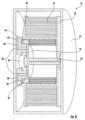
[0052]図3を参照すると、具体的な実施形態において、ギアトレイン42がプラネタリ
ギアトレイン50であってよい。プラネタリギアトレイン50が、セントラルギアまたは
太陽ギア52と、外側リングギア54と、ギアキャリア56と、少なくとも2つのプラネ
タリギア58とを有する。
[0052] Referring to FIG. 3, in specific embodiments,
[0053]図3に示されるように、太陽ギア52がテープハウジング12に堅固に結合され
、プラネタリギアトレイン50とハウジング12との間に固定の接続部48を提供する。
太陽ギア52がギアトレイン50の回転軸を画定し、この回転軸が巻尺10の回転軸28
と同一直線である。示される具体的な実施形態では、太陽ギア52が、テープハウジング
12の内側表面から内側に延在するギア構造である。一実施形態では、太陽ギア52がハ
ウジング12の構成要素と一体に形成または成形される構造であり、別の実施形態では、
太陽ギア52がハウジング12の内側表面に結合される(例えば、接着剤、溶接、摩擦嵌
合などを介する)別個の部片である。
[0053] As shown in FIG. 3, a
A
is the same straight line as In the specific embodiment shown,
[0054]外側リングギア54がリール20に堅固に結合される。図3に示されるように、
外側リングギア54が、リール20から外側に延在する環状フランジ60上に形成される
。理解されるように(図5を参照)、外側リングギア54が、環状フランジ60の概して
円筒形の内側表面から内側に径方向に延在するギア歯を有し、その結果、外側リングギア
54が回転軸28を囲む。いくつかの実施形態では、外側リングギア54およびリール2
0が切れ目のない連続する単一材料部片から一体に形成または成形され、別の実施形態で
は、外側リングギア54がリール20の外側表面に結合される(例えば、接着剤、溶接、
摩擦嵌合などを介する)別個の部片である。
[0054]
An
0 is integrally formed or molded from a single, continuous piece of material, and in another embodiment, the
(through a friction fit, etc.).
[0055]プラネタリギア58がギアキャリア56のポスト62に設置される。ギアキャリ
ア56がアクスル24に堅固に結合される(例えば、回転不可能に)。プラネタリギア5
8のギア歯が外側リングギア54のギア歯および固定の太陽ギア52のギア歯に結合/連
結される。この構成では、テープの延伸中にリール20が回転するとき、外側リングギア
54とプラネタリギア58との間の結合がリール20の回転運動をプラネタリギア58へ
と伝える。プラネタリギア58と太陽ギア52との間の係合を介して、プラネタリギアが
太陽ギア52の周りを「周回」し、これがプラネタリギア58の周回運動をギアキャリア
56へとおよびアクスル24へと伝える。図3に示される具体的な実施形態では、プラネ
タリギアトレイン50によりアクスル24がリール20と同じ方向に回転することになり
、その結果、螺旋構造のばね26が、リール20上のテープ18と同じ方向に巻回される
(渦巻き状となる)。
[0055]
Eight gear teeth are coupled/connected to the gear teeth of
[0056]理解されるように、太陽ギア52と、リングギア54と、プラネタリギア58と
を相対的にサイズ決定することが、リール20とアクスル24との間のギア減速を決定す
ることになる。したがって、このようにギアトレイン構成要素を相対的にサイズ決定する
ことが、プラネタリギアトレイン50のばねの巻数比(上記の式1を参照)を決定するこ
とになる。
[0056] As will be appreciated, the relative sizing of
[0057]図3を参照すると、プラネタリギアトレイン50のギア減速により実現されるこ
とである、ばねのエネルギー密度が増大することと、その結果としてハウジング12内の
スペースを節約することとに加えて、図3に示されるような、ばね26およびリール20
に対してのプラネタリギアトレイン50の配置構成により、スペースをさらに節約するこ
とが実現される。具体的には、図3の実施形態では、ばね26がリール20とアクスル2
4との間に直接に結合され、それにより、リール20の内部チャンバ64の断面直径の全
体を占有するようにばね26をサイズ決定することが可能となる。したがって、このよう
な実施形態では、ばね26の最も外側の一巻きがリール20の円筒形内側表面の方を向く
ようになり、ここではばね26とリール20との間にプラネタリギアトレイン50の構成
要素が位置しない。加えて、一部の遊星ギア構成と比較すると、プラネタリギアトレイン
50がさらには、可動部品の数を相対的に少なくするのを可能にする。さらに、プラネタ
リギアトレイン50は、ハウジング12とリール20/アクスル25との間の幅方向に単
層の歯車装置のみを配置することを理由として、巻尺の幅の増大を相対的に小さいものの
みとする。
[0057] Referring to FIG. 3, in addition to the increased energy density of the springs and the consequent space savings within the
Further space savings are realized by the arrangement of the
4, thereby allowing the
[0058]図5を参照すると、巻尺10が、ギアトレイン70として示される、ギアトレイ
ンを有することができる。ギアトレイン70は、図2に関連して上で考察されるギアトレ
イン42の例示の実施形態である。この実施形態では、ギアトレイン70が、一対の対向
するプラネタリギアトレイン50を有する。図5に示される実施形態では、1つのプラネ
タリギアトレイン50がリール20の一方側に位置し、第2のプラネタリギアトレイン5
0がリール20のもう一方側に位置する。この構成では、ばね26がリール20内に位置
し、かつ回転軸28に沿って2つの対向するプラネタリギアトレイン50の間に位置する
。
[0058] Referring to FIG. 5,
0 is located on the other side of the
[0059]図6~8を参照すると、巻尺10が、ギアトレイン80として示される、ギアト
レインを有することができる。ギアトレイン80は、図2に関連して上で考察されるギア
トレイン42の例示の実施形態である。示されるように、ギアトレイン80は遊星ギアト
レインであり、外側リングギア82と、内側リングギア84と、少なくとも2つのプラネ
タリギア86とを有する。
[0059] Referring to FIGS. 6-8,
[0060]外側リングギア82がリール20に堅固に結合される。図6に示されるように、
外側リングギア54が、リール20から外側に延在する環状フランジ60上に位置する。
理解されるように(図5を参照)、外側リングギア82が、環状フランジ60の概略円筒
形の内側表面から内側に径方向に延在するギア歯を有する。いくつかの実施形態では、外
側リングギア82およびリール20が切れ目のない連続する単一材料部片から一体に形成
または成形され、別の実施形態では、外側リングギア82がリール20の外側表面に結合
される(例えば、接着剤、溶接、摩擦嵌合などを介する)別個の部片である。
[0060]
An
As can be seen (see FIG. 5), the
[0061]各プラネタリギア86が、ハウジング12の内側表面に堅固に結合されるポスト
88に回転式に設置される。ポスト88がテープハウジング12に堅固に結合され、その
結果、プラネタリギア86がハウジング12を基準として平行移動することが防止される
が、ポスト88を中心としてスピンするかまたは回転させられことが可能であり、それに
よりアクスル24へと回転を変換する。このようにして、ポスト88がギアトレイン80
とハウジング12との間に固定の接続部を提供する(図2の接続部48を参照されたい)
。
[0061] Each
and the housing 12 (see
.
[0062]各プラネタリギア86が、外側セクションまたはハイギアセクション90および
内側セクションまたはローギアセクション92を有する。内側リングギア84がプレート
94を介してアクスル24に堅固に結合される。いくつかの実施形態では、内側リングギ
ア84および/またはプレート94が、アクスル24と共に、切れ目のない連続する単一
材料部片から一体に形成または成形され、別の実施形態では、内側リングギア84および
/またはプレート94がアクスル24に結合される(例えば、接着剤、溶接、摩擦嵌合な
どを介する)別個の部片である。
[0062] Each
[0063]テープの延伸中の動作では、外側リングギア82が各プラネタリギア86のハイ
ギアセクション90に係合され、その結果、リール20の回転が各プラネタリギア86の
そのポスト88を中心とした回転へと変換される。各プラネタリギア86のローギアセク
ション92が内側リングギア84に係合され、その結果、プラネタリギア86の回転が内
側リングギア84の回転へと変換される。内側リングギア84とアクスル24との間の堅
固な結合を介して、内側リングギア84の回転によりアクスル24が回転させられる。図
6~8に示される具体的な実施形態では、ギアトレイン80によりアクスル24がリール
20と同じ方向に回転することになり、その結果、螺旋構造ばね26がリール20上のテ
ープ18と同じ方向に巻回される(渦巻き状となる)。
[0063] In operation during tape stretching, the
[0064]図9を参照すると、巻尺10が、ギアトレイン100として示される、ギアトレ
インを有することができる。ギアトレイン100は、図2に関連して上で考察されるギア
トレイン42の例示の実施形態である。示されるように、ギアトレイン100は遊星ギア
トレインであり、小さい太陽ギア102と、大きい太陽ギア104と、少なくとも2つの
プラネタリギア106とを有する。
[0064] Referring to FIG. 9,
[0065]図9に示されるように、小さい太陽ギア102がテープハウジング12に堅固に
結合され、ギアトレイン100とハウジング12との間に固定の接続部48(図2を参照
)を提供する。示される具体的な実施形態では、小さい太陽ギア102が、テープハウジ
ング12の内側表面から内側に延在するギア構造である。一実施形態では、小さい太陽ギ
ア102がハウジング12の構成要素と一体に形成または成形される構造であり、別の実
施形態では、小さい太陽ギア102がハウジング12の内側表面に結合される(例えば、
接着剤、溶接、摩擦嵌合などを介する)別個の部片である。
[0065] As shown in FIG. 9, a
(through adhesive, welding, friction fit, etc.).
[0066]図9に示されるように、大きい太陽ギア104がアクスル24に堅固に結合され
、小さい太陽ギア102の外径より大きい外径を有する。示される具体的な実施形態では
、大きいギア104が、アクスル24の外側端部のうちの一方から回転軸28の方向に外
側に延在するギア構造である。一実施形態では、大きい太陽ギア104がアクスル24の
端部と一体に形成または成形される構造であり、別の実施形態では、大きい太陽ギア10
4がアクスル24の端部に結合される(例えば、接着剤、溶接、摩擦嵌合などを介する)
別個の部片である。
[0066] As shown in FIG. 9, a
4 is coupled to the end of the axle 24 (e.g., via adhesive, welding, friction fit, etc.)
It is a separate piece.
[0067]ギアトレイン100が、ポスト108に設置される少なくとも2つのプラネタリ
ギア106を有する。ポスト108がリール20の外側側方表面から回転軸28に平行な
方向に外側へと延在する。このようにして、ポスト108がプラネタリギア106をリー
ル20に結合する。
[0067]
[0068]各プラネタリギア106が、外側セクションまたはハイギアセクション110お
よび内側セクションまたはローギアセクション112を有する。図9に示されるように、
各ハイギアセクション110の外径がローギアセクション112の外径より大きい。ハイ
ギアセクション110のギア歯が小さい太陽ギア102に係合され、ローギアセクション
112のギア歯が大きい太陽ギア104に係合される。
[0068] Each
The outer diameter of each
[0069]ポスト108を介するリール20とプラネタリギア106の間の結合が、テープ
の延伸中、小さい太陽ギア102の周りでプラネタリギア106を担持する。プラネタリ
ギア106が小さい太陽ギア102の周りを回転または周回するとき、ローギアセクショ
ン112と大きい太陽ギア104との間の係合がアクスル24の回転を始動する。図9に
示される具体的な実施形態では、ギアトレイン100によりアクスル24がリール20と
同じ方向に回転することになり、その結果、螺旋構造ばね26がリール20上のテープ1
8と同じ方向に巻回される(渦巻き状となる)。
[0069] The coupling between
It is wound in the same direction as 8 (it becomes a spiral shape).
[0070]図10を参照すると、巻尺10が、ギアトレイン120として示される、ギアト
レインを有することができる。ギアトレイン120は、図2に関連して上で考察されるギ
アトレイン42の例示の実施形態である。ギアトレイン120は本明細書で考察されるこ
とを除いて図3に示されるギアトレイン42に類似する。示されるように、ギアトレイン
120は遊星ギアトレインであり、セントラルギアまたは太陽ギア52と、外側リングギ
ア54と、ギアキャリア56と、少なくとも2つのプラネタリギア122とを有する。
[0070] Referring to FIG. 10,
[0071]各プラネタリギア122が外側セクションまたはハイギアセクション124およ
び内側セクションまたはローギアセクション126を有する。プラネタリギア122がギ
アキャリア56のポスト128に設置される。プラネタリギア122のローギアセクショ
ン126のギア歯が外側リングギア54のギア歯に結合される。プラネタリギア122の
ハイギアセクション124のギア歯が固定の太陽ギア52のギア歯に結合される。この構
成では、テープの延伸中にリール20が回転するとき、外側リングギア54とプラネタリ
ギア122のローギアセクション126のギア歯との間の結合がリール20の回転運動を
プラネタリギア122へと伝える。プラネタリギア122と太陽ギア52との間の係合を
介して、プラネタリギア122が太陽ギア52の周りを「周回」し、これが周回運動をギ
アキャリア56およびアクスル24へと伝える。図10に示される具体的な実施形態では
、ギアトレイン120によりアクスル24がリール20と同じ方向に回転することになり
、その結果、螺旋構造ばね26がリール20上のテープ18と同じ方向に巻回される(渦
巻き状となる)。
[0071] Each
[0072]図11から18が、追加の例示の実施形態による種々の遊星ギアトレイン構成を
有する巻尺10を示す。概して、図11~18に示されるギアトレイン構成は上で考察し
たギアトレイン構成に類似するが、上記では、ギアトレイン構成がリールとアクスルとの
間でギア減速を実現し、その結果、リールの1回転ごとのばねに適用される巻数が減少す
る。
[0072] FIGS. 11-18 illustrate
[0073]図11を参照すると、ギアキャリア56がハウジング12に結合され、ポスト6
2を有し、このポスト62の周りに内側プラネタリギア92および外側プラネタリギア9
0が回転可能に設置される。外側プラネタリギア90のギア歯が外側リングギア82およ
び内側プラネタリギア92に結合され、さらに内側プラネタリギア92のギア歯が内側リ
ングギア84に結合される。外側リングギア82がアクスル24に結合され、内側リング
ギア84がテープリール20に結合され、ばね26がテープリール20とアクスル24と
の間に結合される。
[0073] Referring to FIG. 11,
2, and an inner
0 is rotatably installed. Gear teeth of outer
[0074]図12を参照すると、ギアキャリア56がテープリール20に結合され、ポスト
62を有し、ポスト62の周りに内側プラネタリギア92および外側プラネタリギア90
が回転可能に設置される。外側プラネタリギア90のギア歯が外側リングギア54および
内側プラネタリギア92に結合され、さらに内側プラネタリギア92のギア歯が太陽ギア
52に結合される。太陽ギア52がハウジング12に結合され、外側リングギア54がア
クスル24に結合され、ばね26がテープリール20とアクスル24との間に結合される
。
[0074] Referring to FIG. 12, a
is installed rotatably. Gear teeth of outer
[0075]図13を参照すると、ギアキャリア56がアクスル24に結合され、ポスト62
を有し、ポスト62の周りに内側プラネタリギア92および外側プラネタリギア90が回
転可能に設置される。外側プラネタリギア90のギア歯が外側リングギア54および内側
プラネタリギア92に結合され、さらに内側プラネタリギア92のギア歯が太陽ギア52
に結合される。外側リングギア54がテープリール20に結合され、太陽ギア52がハウ
ジング12に結合され、ばね26がテープリール20とアクスル24との間に結合される
。
[0075] Referring to FIG. 13,
An inner
is combined with An
[0076]図14を参照すると、ギアキャリア56がアクスル24に結合され、ポスト62
を有し、ポスト62の周りに内側プラネタリギア92および外側プラネタリギア90が回
転可能に設置される。外側プラネタリギア90のギア歯が外側リングギア54および内側
リングギア92に結合され、さらに内側プラネタリギア92のギア歯が太陽ギア52に結
合される。外側リングギア54がテープリール20に結合され、太陽ギア52がハウジン
グ12に結合され、ばね26がテープリール20とアクスル24との間に結合される。
[0076] Referring to FIG. 14, the
An inner
[0077]図15を参照すると、ギアキャリア56がアクスル24に結合され、ポスト62
を有し、ポスト62の周りに内側プラネタリギア92および外側プラネタリギア90が回
転可能に設置される。外側プラネタリギア90のギア歯が外側リングギア82および内側
プラネタリギア92に結合され、さらに内側プラネタリギア92のギア歯が内側リングギ
ア84に結合される。外側リングギア82がテープリール20に結合され、内側リングギ
ア84がハウジング12に結合され、ばね26がテープリール20とアクスル24との間
に結合される。
[0077] Referring to FIG. 15,
An inner
[0078]図16を参照すると、ギアキャリア56がアクスル24に結合される。テープリ
ール20がポスト62を有し、ポスト62の周りにプラネタリギア58が回転可能に設置
される。内側プラネタリギア92のギア歯が外側リングギア82に結合され、外側プラネ
タリギア90のギア歯が内側リングギア84に結合される。外側リングギア82がハウジ
ング12に結合され、内側リングギア84がギアキャリア56に結合され、ばね26がテ
ープリール20とアクスル24との間に結合される。
[0078] Referring to FIG. 16, a
[0079]図17を参照すると、ギアキャリア56がアクスル24に結合される。ポスト6
2がテープリール20に結合され、プラネタリギア58がポスト62に回転可能に設置さ
れる。外側プラネタリギア90のギア歯が外側リングギア82に結合され、内側プラネタ
リギア92のギア歯が内側リングギア84に結合される。外側リングギア82がハウジン
グ12に結合され、内側リングギア84がギアキャリア56に結合され、ばね26がテー
プリール20とアクスル24との間に結合される。
[0079] Referring to FIG. 17, a
2 is coupled to the
[0080]図18を参照すると、ギアキャリア56がアクスル24に結合され、ポスト62
を有し、ポスト62の周りに内側プラネタリギア92および外側プラネタリギア90が回
転可能に設置される。外側プラネタリギア90のギア歯が内側リングギア84および内側
プラネタリギア92に結合され、さらに内側プラネタリギア92のギア歯が外側リングギ
ア82に結合される。内側リングギア84がテープリール20に結合され、外側リングギ
ア82がハウジング12に結合され、ばね26がテープリール20とアクスル24との間
に結合される。
[0080] Referring to FIG. 18,
An inner
[0081]次に図19を参照すると、種々の実施形態において、巻尺10がテープリールま
たはスプール20が回転する間の(例えば、ハウジング12がテープブレード18を送り
出すかまたは回収する間の)摩擦を低減するように構成される1つまたは複数の構造を有
することができる。図19のスプール20の左側で、アクスルまたはキャリア24により
、接触面150のところで、スプール20が径方向において支持される。図19のスプー
ル20の右側で、キャリア24により、スプールカバー132を介して、接触面150の
ところで、スプール20が径方向において間接的に支持される。キャリア24の両側で、
キャリア24自体がハウジング12により接触面150のところで閉じ込められる。
[0081] Referring now to FIG. 19, in various embodiments, the
The
[0082]一実施形態では、キャリア24が5mmの直径を有しダイカストの亜鉛から作ら
れるが、他の直径、製造方法、および/または材料が利用されてもよく、また、他の直径
、製造方法、および/または材料が本明細書の開示を実施してもよいことが、本明細書で
は企図される。
[0082] In one embodiment, the
[0083]スプール20およびスプールカバー132の軸受接触面を含む接触面150が直
接にキャリア24の周りに位置する。キャリア24からより大きい直径のところに軸受面
が位置するような他の実施形態と比較して軸受面の直径が小さいことを理由として、接触
面150の面積が縮小される。その結果、併せて、スプール20が回転する間の摩擦によ
るエネルギー損失量が低減される。したがって、スプール20およびテープブレードを完
全に格納するのを実現するのに必要となるトルクが低減される。
[0083] Contact surfaces 150, including bearing contact surfaces of
[0084]巻尺10がダストカバー130を有し、ダストカバー130が、プラネタリギア
58と太陽ギア52および外側リングギア54の両方との間の結合箇所を少なくとも部分
的に取り囲む(図20に最も良好に示される)。
[0084] The
[0085]図19の実施形態では、本明細書で説明される1つまたは複数の他の実施形態と
同様に、ばね26がキャリア24およびスプール20に固着され、プラネタリギア58が
太陽ギア52に結合されてその周りを回転する(図20に最も良好に示される)。さらに
、プラネタリギア58の外周が外側リングギア54に結合される。スプール20(テープ
リール20とも称される)およびキャリア24(アクスル24とも称される)の両方が、
アクスル24の長手方向軸を中心として、ハウジング12内でハウジング12に対して回
転する。
[0085] In the embodiment of FIG. 19, like one or more other embodiments described herein,
[0086]次に図21を参照すると、巻尺10が、ダストカバー130に対してスプール2
0の反対側に位置するスプールカバー132をさらに有することができる。スプールカバ
ー132がスプール20の内部チャンバ64を少なくとも部分的に取り囲み、内部チャン
バ64の中にばね26が配置される。スプールカバー132がスプール20に回転可能に
固定され、キャリア24を中心として回転する。スプールカバー132内の突起部が、組
み立て時にスプール20に容易に回転ロックをかけるのを可能にする。支持リング134
がスプールカバー132とスプール20との間のより確実な結合を促進し、それにより巻
尺10が落下してしまう場合に外れる可能性を低減する。代替的実施形態では、スプール
カバー132がスプール20に固定されず、代わりに、キャリア24およびスプール20
の両方から独立して回転することが可能である。
[0086] Referring now to FIG. 21, the
0 may further include a
promotes a more secure connection between the
It is possible to rotate independently from both.
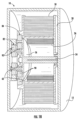
[0087]次に図22を参照すると、巻尺10の別の実施形態がこの図に示されている。こ
の実施形態では、巻尺10が、巻尺10の主要な質量(通常、テープブレード18および
ばね26)からハウジング12への直接的な荷重経路を形成するように設計され、それに
より例えば巻尺10が落下してしまう場合に衝撃を受けるときの耐久性および安定性を向
上させる。この実施形態の別の態様および利点は、入力トルクが、太陽ギア52/前方ハ
ウジング12のところに作用するトルクを小さくするような形でより多い巻数へと変換さ
れ、それによりテープリール20を回転させる、ということである。
[0087] Referring now to FIG. 22, another embodiment of a
[0088]図22に示される実施形態では、ばね26がキャリア24およびスプール20に
固着される。キャリア24がハウジング12およびスプール20を基準として自由にスピ
ンする。さらに、テープブレード18が送り出されるかまたはハウジング12の中へと回
収される場合、キャリア24がスプール20と同じ方向にスピンするが、その速度がスプ
ール20よりわずかに低い。
[0088] In the embodiment shown in FIG. 22,
[0089]この実施形態では、スプール20が、図22の右側でハウジング12により接触
面150のところで、また図22の左側においてハブキャップ140により接触面150
のところで、径方向において支持される。スプール20およびハブキャップ140の軸受
接触面を含む接触面150が、図22に示されるように、ハウジング12の周りに位置す
る。したがって、図19と比較して、図22の軸受面の直径が相対的に大きいことを理由
として、接触面150の面積がわずかに増大する。
[0089] In this embodiment, the
is supported in the radial direction. Contact surfaces 150, including bearing contact surfaces of
[0090]ハブキャップ140がプラネタリギア58と外側リングギア54との間の結合箇
所を部分的に取り囲む。ハブキャップ140がスプール20に回転可能に固定される(例
えば、リベット、ねじ、および/または固定具を介する)。図22に示される実施形態で
は、ハブキャップ140が環状フランジ60から延在してプラネタリギア58の径方向内
側縁部に接近する。この構成では、ハブキャップ140がギア組立体に汚染物質が入るの
を防止するのを補助する。しかし、ハブキャップ140が他の構成を有してもよいことが
本明細書では企図される。
[0090] A
[0091]図22の実施形態には膜142も含まれる。膜142が、太陽ギア52と、プラ
ネタリギア58と、外側リングギア54とを含むギアから内部チャンバ64を分離する(
図22および23に最も良好に示される)。一実施形態では、外側リングギア54がスプ
ール20内の開口部内に配置されるように構成され(図23に最も良好に示される)、そ
の結果、外側リングギア54およびスプール20が回転可能に一体に固定される。
[0091] The embodiment of FIG. 22 also includes a
best shown in Figures 22 and 23). In one embodiment,
[0092]次に図24を参照すると、キャリア24の例示の実施形態がこの図に示されてい
る。この実施形態では、キャリア24がギアキャリア56を有し、ギアキャリア56がキ
ャリア24の主軸から径方向に延在する。ギアキャリア56から複数のポスト62が突出
し、ポスト62上にプラネタリギア58が配置され、ポスト62を軸としてその周りでプ
ラネタリギア58が回転する。図24に示される実施形態では、キャリア24が5つのポ
スト62を有するが、本明細書では、限定しないが単に例示としては3つから6つのポス
トなどの任意の数のポストが利用されてよいことが企図される。さらに、図24などの、
1つまたは複数の実施形態では、ポスト62が互いを基準としてギアキャリア56上で対
称に位置する。キャリア56が円形として示されるが、他の実施形態ではキャリア56が
、六角形、D形、楕円形、X角形などの、任意の適切な他の形状であってもよことを理解
されたい。
[0092] Referring now to FIG. 24, an exemplary embodiment of
In one or more embodiments, posts 62 are positioned symmetrically on
[0093]一実施形態では、キャリア24が4.63mmの直径を有し、ダイカストの亜鉛
から作られるが、他の直径、製造方法、および/または材料が利用されてもよく、また、
他の直径、製造方法、および/または材料が本明細書の1つまたは複数の開示を実施して
もよいことが本明細書では企図される。
[0093] In one embodiment,
It is contemplated herein that other diameters, manufacturing methods, and/or materials may implement one or more of the disclosures herein.
[0094]次に図25を参照すると、巻尺10などの遊星ギア式の巻尺(epicycli
c geared tape measure)の組立方法が示されている。ステップ1
で、膜142の一方側がグリースなどでわずかに潤滑される。膜142がキャリア24上
に据え付けられ、ここでは膜142のグリースを差された側がキャリア24の方を向く。
ステップ2でばね26がキャリア24のアクスルの周りに形成され、巻かれる。ステップ
3で、ばね26の外側テール部分が捕捉され、スプール20がばね26の周りに配置され
、ばね26の外側テール部分がスプール20に固着される。
[0094] Referring now to FIG. 25, a planetary gear tape measure, such as
c geared tape measurement) is shown.
Then, one side of the
[0095]ステップ4で、プラネタリギア58がプラネタリギア58とポスト62との間で
わずかに潤滑され(例えば、グリースを用いる)、プラネタリギア58がポスト62上に
配置される。ステップ5で、外側リングギア54がプラネタリギア58の周りに配置され
、プラネタリギア58の歯がわずかに潤滑される。次いで、ステップ6で、ハブキャップ
140がギア組立体の上に配置されてスプール20に固定的に取り付けられる(例えば、
ねじを介する)。次いで、ステップ7で、スプール組立体が、太陽ギア52を有するハウ
ジング12(例えば、前方ハウジング)の中に配置され、その結果、プラネタリギア58
が太陽ギア52に結合される。その後、ステップ8で、後方ハウジング、バンパ、ブレー
キ、および/またはハウジングの取り付けのためのハウジングのねじ、を取り付けるなど
して、巻尺10の残り部分が組み立てられる。
[0095] In
(through screws). The spool assembly is then placed in the housing 12 (e.g., the front housing) having the
is coupled to
[0096]スプール20に対してのアーバ24の相対回転速度は、テープブレード18およ
びばね26が同じ方向に巻かれているか否かに部分的に基づく。ブレード18およびばね
26を異なる方向に巻くことの結果を例証するために、以下で2つの実施形態を説明する
。いずれの実施形態でも、ばね26が、一方の端部においてスプール20に固着され、も
う一方の端部においてアーバ24に固着される。使用中、テープブレード18が延伸させ
られるかまたは格納されるとき、スプール20およびアーバ24が互いに同じ方向に回転
する。スプール20およびアーバ24の両方がギアトレイン42を介してハウジング12
に結合される。テープブレード18がスプール20の周りに巻かれ、テープブレード18
がハウジング12から延伸させられるとき、アーバ24およびスプール20の回転を介し
てエネルギーがばね26内に保存される。
[0096] The relative rotational speed of
is combined with
Energy is stored in
[0097]第1の実施形態では、ばね26およびテープブレード18が同じ方向に巻かれ、
その結果、スプール20がアーバ24より速く回転する。例えば、この実施形態で4:1
のばねの巻数比が利用される場合、スプール20が4回転すると、アーバ24が3回転し
、その結果、一巻分の力がばね26に加えられることになる(ハウジング12、ばね26
、スプール20、およびアーバ24が直列である一般的な巻尺における4巻に代えて)。
[0097] In the first embodiment, the
As a result,
If a spring turns ratio of
,
[0098]第2の実施形態では、ケースばね26およびテープブレード18が反対方向に巻
かれ、その結果、アーバ24がスプール20よりも速く回転する。比較のためにこの実施
形態で4:1のばねの巻数比を利用すると、スプール20が4回転すると、アーバ24が
5回転し、その結果、一巻きがばねに適用されることになる(一般的な巻尺における4巻
に代えて)。
[0098] In the second embodiment,
[0099]図が例示の実施形態を詳細に示していること、および本出願が本説明に記載され
るかまたは図に示される細部または方法のみに限定されないことを理解されたい。また、
用語が説明することのみを目的としており、限定するものとしてみなされるべきではない
ことを理解されたい。
[0099] It is to be understood that the figures depict example embodiments in detail and that this application is not limited to only the details or methodologies set forth in the description or shown in the figures. Also,
It is to be understood that the terms are for descriptive purposes only and are not to be considered limiting.
[0100]本記述を考慮すると、当業者には、本発明の種々の態様の別の修正形態および代
替的実施形態が明らかとなろう。したがって、本記述は単に例示的であると解釈される。
種々の例示の実施形態に示される構造および構成は単に例示である。本開示ではいくつか
の実施形態のみを詳細に説明してきたが、本明細書で説明される主題の新規な教示および
利点から実質的に逸脱することなく、多くの修正形態が可能である(例えば、種々の要素
のサイズ、寸法、構造、形状、および比率、パラメータ値、設置構成、材料の使用、色、
向き、などの変更)。一体に形成されると示される一部の要素は複数の部品または要素か
ら構築されてもよく、要素の位置は逆にされるかまたは他の形で変更されてもよく、別個
の要素または位置の性質または数は修正または変更され得る。任意のプロセス、論理アル
ゴリズム、または方法ステップの順序または並びは、代替的実施形態に従って、変更され
てよいかまたは並び直されてよい。また、本発明の範囲から逸脱することなく、種々の例
示の実施形態の設計、動作条件、および構成において、他の置き換え、修正、変更、およ
び省略が行われてもよい。
[0100] Other modifications and alternative embodiments of various aspects of the invention will be apparent to those skilled in the art upon consideration of this description. Accordingly, this description is to be construed as illustrative only.
The structures and configurations shown in the various example embodiments are merely exemplary. Although this disclosure has described only certain embodiments in detail, many modifications are possible without departing materially from the novel teachings and advantages of the subject matter described herein (e.g. , the size, dimensions, structure, shape and proportions of the various elements, parameter values, installation configuration, use of materials, color,
changes in orientation, etc.). Some elements shown as integrally formed may be constructed from multiple parts or elements, and the position of the elements may be reversed or otherwise altered, and some elements may be separated from separate elements or positions. The nature or number of may be modified or changed. The order or sequence of any process, logical algorithm, or method steps may be changed or rearranged according to alternative embodiments. Additionally, other substitutions, modifications, changes, and omissions may be made in the design, operating conditions, and arrangement of the various exemplary embodiments without departing from the scope of the invention.
[0101]特に明記しない限り、本明細書に記載されるいかなる方法も、そのステップを特
定の順序で実施するのを必要とすると解釈されることを意図されない。したがって、方法
クレームがそのステップが従うことになる順序を実際的に列記しているわけではなく、ま
たステップを特定の順序のみに限定することを特許請求の範囲および本記述で具体的に述
べているわけでもない場合、特定の順序を意味することが意図されているわけではない。
また、本明細書で使用される冠詞「a」は1つまたは複数の構成要素または要素を含むこ
とを意図され、1つのみを意味するものとして解釈されることを意図されない。本明細書
で使用される「堅固に結合される」は、力の作用時に2つの構成要素が固定される位置関
係で共に移動するような形で2つの構成要素が結合されていることを意味する。
[0101] Unless stated otherwise, no method described herein is intended to be construed as requiring its steps to be performed in a particular order. Therefore, the method claims do not substantively recite the order in which the steps are to be followed, and the claims and this description do not specifically state that the steps are limited to only a particular order. No particular order is intended.
Also, as used herein, the article "a" is intended to include one or more components or elements, and is not intended to be construed as meaning only one. As used herein, "rigidly coupled" means that two components are coupled in such a way that the two components move together in a fixed relationship when a force is applied. do.
[0102]本発明の種々の実施形態は複数の特徴のうちの任意の特徴の任意の組み合わせに関連し、このような特徴の任意の組み合わせが本出願または将来の出願で特許請求され得る。上で考察される例示の実施形態のうちの任意の実施形態の特徴、要素、または構成要素のうちの任意のものはすべて、単独で使用されてもよく、あるいは上で考察した他の実施形態のうちの任意の実施形態の特徴、要素、または構成要素のうちの任意のものとの組み合わせで使用されてもよい。
[付記]
[形態1]
巻尺であって、
ハウジングと、
前記ハウジング内に回転可能に設置されるアクスルと、
前記ハウジング内で前記アクスルの周りに回転可能に設置されるテープリールであって、前記テープリールが、リール内部キャビティを画定する径方向内側の表面、および径方向外側の表面を備える、テープリールと、
前記テープリールの前記径方向外側の表面の周りに巻かれる細長いテープブレードと、 前記細長いテープブレードの外側端部に結合されるフック組立体と、
前記リール内部キャビティ内に少なくとも部分的に位置して径方向において前記細長いテープブレードにより少なくとも部分的に囲まれる渦巻きばねであって、前記渦巻きばねが前記テープリールと前記アクスルとの間に結合され、その結果、前記細長いテープブレードが前記テープリールからほどかれて前記ハウジングから延伸するとき、前記渦巻きばねがエネルギーを保存し、前記渦巻きばねがエネルギーを解放すると、前記細長いテープブレードを前記テープリール上に再び巻くのを始動する、渦巻きばねと、
前記ハウジングからの前記細長いテープブレードの延伸中に、前記テープリールが完全に1回転するごとに前記アクスルが1回転未満で回転するように、前記テープリールおよび前記アクスルを回転可能に結合させるギアトレインと
を備え、
前記細長いテープブレードを延伸させるときおよび再び巻くとき、前記アクスルおよび前記テープリールの両方が前記ハウジング内で回転する、
巻尺。
[形態2]
形態1に記載の巻尺において、前記ギアトレインの第1のギアが前記ハウジングに結合され、前記細長いテープブレードが前記ハウジングからの延伸時に凹形のプロフィールを有する上側面を有する、巻尺。
[形態3]
形態2に記載の巻尺において、前記第2のギアが前記ハウジングを基準として回転しないように、前記ギアトレインの第2のギアが前記ハウジングに固定的に結合される、巻尺。
[形態4]
形態2に記載の巻尺において、前記第2のギアが前記ハウジングを基準として回転するように、前記ギアトレインの第2のギアが前記ハウジングに回転可能に結合される、巻尺。
[形態5]
形態1に記載の巻尺において、前記アクスルが前記アクスルの端部から径方向外側に延在するギアキャリアを備え、前記ギアキャリアが前記アクスルの主軸に平行な軸に沿って延在する複数のポストを備え、前記ギアトレインが、
前記ハウジングに固定的に結合される太陽ギアと、
前記テープリールに固定的に結合される外側リングギアと、
前記複数のポストに回転可能に設置される複数のプラネタリギアであって、前記複数のプラネタリギアが前記外側リングギアおよび前記太陽ギアに回転可能に係合される、複数のプラネタリギアと
を備える、巻尺。
[形態6]
形態1に記載の巻尺において、
前記アクスルが前記アクスルの端部から径方向外側に延在するギアキャリアを備え、前記ギアトレインが、
前記テープリールに固定的に結合される第1の外側リングギアと、
前記ギアキャリアに固定的に結合される第2の外側リングギアと、
前記ハウジングに固定的に結合される複数のポストと、
前記複数のポストに回転可能に設置される複数のプラネタリギアであって、前記複数のプラネタリギアの各々が、軸方向において位置合わせされて互いに固定的に結合されて互いに異なる半径を有する低速プラネタリギアおよび高速プラネタリギアを備え、前記低速プラネタリギアが前記第2の外側リングギアに回転可能に係合され、前記高速プラネタリギアが前記第1の外側リングギアに回転可能に係合される、複数のプラネタリギアと
を備える、巻尺。
[形態7]
形態6に記載の巻尺において、各低速プラネタリギアが第1の半径を有し、各高速プラネタリギアが第2の半径を有し、前記第1の半径が前記第2の半径より小さい、巻尺。
[形態8]
形態1に記載の巻尺において、
前記ギアトレインが、
前記アクスルに固定的に結合される大きい太陽ギアと、
前記ハウジングに固定的に結合される小さい太陽ギアであって、前記小さい太陽ギアが前記大きい太陽ギアの半径より小さい半径を有する、小さい太陽ギアと、
前記テープリールに固定的に結合される複数のポストであって、前記複数のポストの各々が前記アクスルの主軸に平行な軸に沿って延在する、複数のポストと、
前記複数のポストに回転可能に設置される複数のプラネタリギアであって、前記複数のプラネタリギアの各々が一体に固定的に結合される高速プラネタリギアおよび低速プラネタリギアを備え、前記高速プラネタリギアが前記小さい太陽ギアに回転可能に係合され、前記低速プラネタリギアが前記大きい太陽ギアに回転可能に係合される、複数のプラネタリギアと、
を備える、巻尺。
[形態9]
形態1に記載の巻尺において、前記テープリールが、前記アクスルの径方向外側の表面に係合される径方向内側の表面を備える、巻尺。
[形態10]
形態9に記載の巻尺において、前記テープリールが前記テープリールの前記リール内部キャビティを部分的に画定する内側壁を備え、前記内側壁が前記アクスルの主軸に対して垂直に延在し、前記径方向内側の表面を備える、巻尺。
[形態11]
形態10に記載の巻尺において、前記巻尺が前記内側壁の反対側で前記リール内部キャビティを部分的に画定するスプールカバーを備え、前記スプールカバーが、前記アクスルの第2の径方向外側の表面に係合される第2の径方向内側の表面を備える、巻尺。
[形態12]
形態1に記載の巻尺において、前記ハウジングからの前記細長いテープブレードの延伸中、アクスルの回転に対するテープリールの回転の比が1より大きく、2未満である、巻尺。
[形態13]
形態1に記載の巻尺において、前記ハウジングからの前記細長いテープブレードの延伸中、アクスルの回転に対するテープリールの回転の比が1.2より大きく、1.5未満である、巻尺。
[形態14]
巻尺であって、
ハウジングと、
前記ハウジング内に回転可能に設置されるアクスルと、
前記ハウジング内で前記アクスルの周りに回転可能に設置されるテープリールであって、前記テープリールが、リール内部キャビティを画定する径方向内側の表面、および径方向外側の表面を備える、テープリールと、
前記テープリールの前記径方向外側の表面の周りに巻かれる細長いテープブレードと、 前記細長いテープブレードの外側端部に結合されるフック組立体と、
前記リール内部キャビティ内に少なくとも部分的に位置して径方向において前記細長いテープブレードにより少なくとも部分的に囲まれる渦巻きばねであって、前記渦巻きばねが前記テープリールと前記アクスルとの間に結合され、その結果、前記細長いテープブレードが前記テープリールからほどかれて前記ハウジングから延伸するとき、前記渦巻きばねがエネルギーを保存し、前記渦巻きばねがエネルギーを解放すると、前記細長いテープブレードを前記テープリール上に再び巻くのを始動する、渦巻きばねと、
前記ハウジングからの前記細長いテープブレードの延伸中に、前記アクスルおよび前記テープリールが同じ回転方向に回転するように、前記テープリールおよび前記アクスルを回転可能に結合させるギアトレインと
を備える、巻尺。
[形態15]
形態14に記載の巻尺において、前記ギアトレインの第1のギアが前記ハウジングに結合され、前記細長いテープブレードが前記ハウジングからの延伸時に凹形のプロフィールを有する上側面を有する、巻尺。
[形態16]
形態14に記載の巻尺において、前記ギアトレインの第1のギアが前記ハウジングに回転可能に結合され、前記細長いテープブレードが前記ハウジングからの延伸時に凹形のプロフィールを有する上側面を有する、巻尺。
[形態17]
形態14に記載の巻尺において、前記アクスルが前記アクスルの端部から径方向外側に延在するギアキャリアを備え、前記ギアキャリアが前記アクスルの主軸に平行な軸に沿って延在する複数のポストを備え、前記ギアトレインが、
前記ハウジングに固定的に結合される太陽ギアと、
前記テープリールに固定的に結合される外側リングギアと、
前記複数のポストに回転可能に設置される複数のプラネタリギアであって、前記複数のプラネタリギアが前記外側リングギアおよび前記太陽ギアに回転可能に係合される、複数のプラネタリギアと
を備える、巻尺。
[形態18]
形態14に記載の巻尺において、前記アクスルが前記アクスルの端部から径方向外側に延在するギアキャリアを備え、前記ギアトレインが、
前記テープリールに固定的に結合される第1の外側リングギアと、
前記ギアキャリアに固定的に結合される第2の外側リングギアと、
前記ハウジングに固定的に結合される複数のポストと、
前記複数のポストに回転可能に設置される複数のプラネタリギアであって、前記複数のプラネタリギアの各々が、軸方向において位置合わせされて互いに固定的に結合されて互いに異なる半径を有する低速プラネタリギアおよび高速プラネタリギアを備え、前記低速プラネタリギアが前記第2の外側リングギアに回転可能に係合され、前記高速プラネタリギアが前記第1の外側リングギアに回転可能に係合される、複数のプラネタリギアと
を備える、巻尺。
[形態19]
形態18に記載の巻尺において、各低速プラネタリギアが第1の半径を有し、各高速プラネタリギアが第2の半径を有し、前記第1の半径が前記第2の半径より小さい、巻尺。
[形態20]
形態14に記載の巻尺において、
前記ギアトレインが、
前記アクスルに固定的に結合される大きい太陽ギアと、
前記ハウジングに固定的に結合される小さい太陽ギアであって、前記小さい太陽ギアが前記大きい太陽ギアの半径より小さい半径を有する、小さい太陽ギアと、
前記テープリールに固定的に結合される複数のポストであって、前記複数のポストの各々が前記アクスルの主軸に平行な軸に沿って延在する、複数のポストと、
前記複数のポストに回転可能に設置される複数のプラネタリギアであって、前記複数のプラネタリギアの各々が一体に固定的に結合される高速プラネタリギアおよび低速プラネタリギアを備え、前記高速プラネタリギアが前記小さい太陽ギアに回転可能に係合され、前記低速プラネタリギアが前記大きい太陽ギアに回転可能に係合される、複数のプラネタリギアと
備える、巻尺。
[形態21]
形態14に記載の巻尺において、前記テープリールが前記テープリールの前記リール内部キャビティを部分的に画定する内側壁を備え、前記内側壁が前記アクスルの主軸に対して垂直に延在し、前記径方向内側表面を備える、巻尺。
[形態22]
形態21に記載の巻尺において、前記巻尺が前記内側壁の反対側で前記リール内部キャビティを部分的に画定するスプールカバーを備え、前記スプールカバーが、前記アクスルの第2の径方向外側の表面に係合される第2の径方向内側の表面を備える、巻尺。
[形態23]
巻尺であって、
ハウジングと、
前記ハウジング内に回転可能に設置されるアクスルと、
前記ハウジング内で前記アクスルの周りに回転可能に設置されるテープリールであって、前記テープリールが、リール内部キャビティを画定する径方向内側の表面、および径方向外側の表面を備える、テープリールと、
前記テープリールの前記径方向外側の表面の周りに巻かれる細長いテープブレードであって、前記細長いテープブレードが前記ハウジングからの延伸時に凹形のプロフィールを有する上側面を有する、細長いテープブレードと、
前記細長いテープブレードの外側端部に結合されるフック組立体と、
前記リール内部キャビティ内に少なくとも部分的に位置して径方向において前記細長いテープブレードにより少なくとも部分的に囲まれる渦巻きばねであって、前記渦巻きばねが前記テープリールと前記アクスルとの間に結合され、その結果、前記細長いテープブレードが前記テープリールからほどかれて前記ハウジングから延伸するとき、前記渦巻きばねがエネルギーを保存し、前記渦巻きばねがエネルギーを解放すると、前記細長いテープブレードを前記テープリール上に再び巻くのを始動する、渦巻きばねと、
前記ハウジングからの前記細長いテープブレードの延伸中に、前記テープリールが完全に1回転するごとに前記アクスルが完全な1回転未満で回転するように、前記テープリールおよび前記アクスルを回転可能に結合させるギアトレインと
を備え、
前記細長いテープブレードを延伸させるときまたは再び巻くとき、前記アクスルおよび前記テープリールが互いに異なる回転速度で前記ハウジング内で回転する、
巻尺。
[形態24]
形態23に記載の巻尺において、前記ギアトレインの第1のギアが前記ハウジングに結合される、巻尺。
[形態25]
形態23に記載の巻尺において、前記ギアトレインの第1のギアが前記ハウジングに回転可能に結合される、巻尺。
[形態26]
形態23に記載の巻尺において、前記アクスルが前記アクスルの端部から径方向外側に延在するギアキャリアを備え、前記ギアキャリアが前記アクスルの主軸に平行な軸に沿って延在する複数のポストを備え、前記ギアトレインが、
前記ハウジングに固定的に結合される太陽ギアと、
前記テープリールに固定的に結合される外側リングギアと、
前記複数のポストに回転可能に設置される複数のプラネタリギアであって、前記複数のプラネタリギアが前記外側リングギアおよび前記太陽ギアに回転可能に係合される、複数のプラネタリギアと
を備える、巻尺。
[形態27]
形態23に記載の巻尺において、
前記アクスルが前記アクスルの端部から径方向外側に延在するギアキャリアを備え、前記ギアトレインが、
前記テープリールに固定的に結合される第1の外側リングギアと、
前記ギアキャリアに固定的に結合される第2の外側リングギアと、
前記ハウジングに固定的に結合される複数のポストと、
前記複数のポストに回転可能に設置される複数のプラネタリギアであって、前記複数のプラネタリギアの各々が、軸方向において位置合わせされて互いに固定的に結合されて互いに異なる半径を有する低速プラネタリギアおよび高速プラネタリギアを備え、前記低速プラネタリギアが前記第2の外側リングギアに回転可能に係合され、前記高速プラネタリギアが前記第1の外側リングギアに回転可能に係合される、複数のプラネタリギアと
を備え、
各低速プラネタリギアが第1の半径を有し、各高速プラネタリギアが第2の半径を有し、前記第1の半径が前記第2の半径より小さい、
巻尺。
[形態28]
形態23に記載の巻尺において、
前記ギアトレインが、
前記アクスルに固定的に結合される大きい太陽ギアと、
前記ハウジングに固定的に結合される小さい太陽ギアであって、前記小さい太陽ギアが前記大きい太陽ギアの半径より小さい半径を有する、小さい太陽ギアと、
前記テープリールに固定的に結合される複数のポストであって、前記複数のポストの各々が前記アクスルの主軸に平行な軸に沿って延在する、複数のポストと、
前記複数のポストに回転可能に設置される複数のプラネタリギアであって、前記複数のプラネタリギアの各々が一体に固定的に結合される高速プラネタリギアおよび低速プラネタリギアを備え、前記高速プラネタリギアが前記小さい太陽ギアに回転可能に係合され、前記低速プラネタリギアが前記大きい太陽ギアに回転可能に係合される、複数のプラネタリギアと、
を備える、巻尺。
[0102] Various embodiments of the invention relate to any combination of any of a plurality of features, and any combination of such features may be claimed in this or future applications. Any of the features, elements, or components of any of the example embodiments discussed above may be used alone or with other embodiments discussed above. may be used in combination with any of the features, elements, or components of any of the embodiments.
[Additional notes]
[Form 1]
A tape measure,
housing and
an axle rotatably installed within the housing;
a tape reel rotatably mounted within the housing about the axle, the tape reel having a radially inner surface defining a reel interior cavity and a radially outer surface; ,
an elongate tape blade wrapped around the radially outer surface of the tape reel; and a hook assembly coupled to the outer end of the elongate tape blade.
a spiral spring located at least partially within the reel interior cavity and radially surrounded at least partially by the elongate tape blade, the spiral spring being coupled between the tape reel and the axle; As a result, as the elongate tape blade unwinds from the tape reel and extends from the housing, the spiral spring stores energy, and when the spiral spring releases energy, it moves the elongate tape blade onto the tape reel. a spiral spring that starts winding again;
a gear train rotatably coupling the tape reel and the axle such that the axle rotates less than one revolution for each complete revolution of the tape reel during extension of the elongated tape blade from the housing; and
both the axle and the tape reel rotate within the housing when stretching and rewinding the elongated tape blade;
Tape measure.
[Form 2]
The tape measure of
[Form 3]
The tape measure according to
[Form 4]
The tape measure according to
[Form 5]
The tape measure according to
a sun gear fixedly coupled to the housing;
an outer ring gear fixedly coupled to the tape reel;
a plurality of planetary gears rotatably installed on the plurality of posts, the plurality of planetary gears being rotatably engaged with the outer ring gear and the sun gear; Tape measure.
[Form 6]
In the tape measure according to
the axle includes a gear carrier extending radially outwardly from an end of the axle, the gear train comprising:
a first outer ring gear fixedly coupled to the tape reel;
a second outer ring gear fixedly coupled to the gear carrier;
a plurality of posts fixedly coupled to the housing;
a plurality of planetary gears rotatably installed on the plurality of posts, each of the plurality of planetary gears being aligned in the axial direction and fixedly coupled to each other, and having different radii; and a high speed planetary gear, the low speed planetary gear being rotatably engaged to the second outer ring gear, and the high speed planetary gear being rotatably engaged to the first outer ring gear. A tape measure equipped with a planetary gear.
[Form 7]
The tape measure of
[Form 8]
In the tape measure according to
The gear train is
a large sun gear fixedly coupled to the axle;
a small sun gear fixedly coupled to the housing, the small sun gear having a radius smaller than the radius of the large sun gear;
a plurality of posts fixedly coupled to the tape reel, each of the plurality of posts extending along an axis parallel to a major axis of the axle;
A plurality of planetary gears rotatably installed on the plurality of posts, each of the plurality of planetary gears including a high-speed planetary gear and a low-speed planetary gear that are fixedly coupled together, the high-speed planetary gear a plurality of planetary gears rotatably engaged to the small sun gear, and the low speed planetary gear rotatably engaged to the large sun gear;
Equipped with a tape measure.
[Form 9]
The tape measure according to
[Form 10]
The tape measure according to aspect 9, wherein the tape reel includes an inner wall partially defining the internal reel cavity of the tape reel, the inner wall extending perpendicularly to the main axis of the axle, A tape measure with a directional inner surface.
[Form 11]
A tape measure according to
[Form 12]
The tape measure of
[Form 13]
The tape measure of
[Form 14]
A tape measure,
housing and
an axle rotatably installed within the housing;
a tape reel rotatably mounted within the housing about the axle, the tape reel having a radially inner surface defining a reel interior cavity and a radially outer surface; ,
an elongate tape blade wrapped around the radially outer surface of the tape reel; and a hook assembly coupled to the outer end of the elongate tape blade.
a spiral spring located at least partially within the reel interior cavity and radially surrounded at least partially by the elongate tape blade, the spiral spring being coupled between the tape reel and the axle; As a result, as the elongate tape blade unwinds from the tape reel and extends from the housing, the spiral spring stores energy, and when the spiral spring releases energy, it moves the elongate tape blade onto the tape reel. a spiral spring that starts winding again;
a gear train rotatably coupling the tape reel and the axle such that the axle and the tape reel rotate in the same direction of rotation during extension of the elongated tape blade from the housing.
[Form 15]
15. The tape measure of
[Form 16]
15. The tape measure of
[Form 17]
15. The tape measure according to
a sun gear fixedly coupled to the housing;
an outer ring gear fixedly coupled to the tape reel;
a plurality of planetary gears rotatably installed on the plurality of posts, the plurality of planetary gears being rotatably engaged with the outer ring gear and the sun gear; Tape measure.
[Form 18]
The tape measure according to
a first outer ring gear fixedly coupled to the tape reel;
a second outer ring gear fixedly coupled to the gear carrier;
a plurality of posts fixedly coupled to the housing;
a plurality of planetary gears rotatably installed on the plurality of posts, each of the plurality of planetary gears being aligned in the axial direction and fixedly coupled to each other, and having different radii; and a high speed planetary gear, the low speed planetary gear being rotatably engaged to the second outer ring gear, and the high speed planetary gear being rotatably engaged to the first outer ring gear. A tape measure equipped with a planetary gear.
[Form 19]
19. The tape measure of
[Form 20]
In the tape measure according to
The gear train is
a large sun gear fixedly coupled to the axle;
a small sun gear fixedly coupled to the housing, the small sun gear having a radius smaller than the radius of the large sun gear;
a plurality of posts fixedly coupled to the tape reel, each of the plurality of posts extending along an axis parallel to a major axis of the axle;
A plurality of planetary gears rotatably installed on the plurality of posts, each of the plurality of planetary gears including a high-speed planetary gear and a low-speed planetary gear that are fixedly coupled together, the high-speed planetary gear A tape measure comprising a plurality of planetary gears rotatably engaged to the small sun gear and the low speed planetary gear rotatably engaged to the large sun gear.
[Form 21]
15. The tape measure according to
[Form 22]
22. The tape measure of aspect 21, wherein the tape measure includes a spool cover partially defining the reel interior cavity opposite the inner wall, the spool cover being on a second radially outer surface of the axle. A tape measure comprising a second radially inner surface that is engaged.
[Form 23]
A tape measure,
housing and
an axle rotatably installed within the housing;
a tape reel rotatably mounted within the housing about the axle, the tape reel having a radially inner surface defining a reel interior cavity and a radially outer surface; ,
an elongate tape blade wrapped around the radially outer surface of the tape reel, the elongate tape blade having an upper surface having a concave profile upon extension from the housing;
a hook assembly coupled to an outer end of the elongated tape blade;
a spiral spring located at least partially within the reel interior cavity and radially surrounded at least partially by the elongate tape blade, the spiral spring being coupled between the tape reel and the axle; As a result, as the elongate tape blade unwinds from the tape reel and extends from the housing, the spiral spring stores energy, and when the spiral spring releases energy, it moves the elongate tape blade onto the tape reel. a spiral spring that starts winding again;
the tape reel and the axle are rotatably coupled such that the axle rotates less than one full revolution for each complete revolution of the tape reel during extension of the elongated tape blade from the housing; Equipped with a gear train,
the axle and tape reel rotate within the housing at different rotational speeds when stretching or rewinding the elongated tape blade;
Tape measure.
[Form 24]
24. The tape measure of form 23, wherein a first gear of the gear train is coupled to the housing.
[Form 25]
24. The tape measure of aspect 23, wherein a first gear of the gear train is rotatably coupled to the housing.
[Form 26]
24. The tape measure according to aspect 23, wherein the axle includes a gear carrier extending radially outward from an end of the axle, the gear carrier having a plurality of posts extending along an axis parallel to the main axis of the axle. , the gear train comprising:
a sun gear fixedly coupled to the housing;
an outer ring gear fixedly coupled to the tape reel;
a plurality of planetary gears rotatably installed on the plurality of posts, the plurality of planetary gears being rotatably engaged with the outer ring gear and the sun gear; Tape measure.
[Form 27]
In the tape measure according to Form 23,
the axle includes a gear carrier extending radially outwardly from an end of the axle, the gear train comprising:
a first outer ring gear fixedly coupled to the tape reel;
a second outer ring gear fixedly coupled to the gear carrier;
a plurality of posts fixedly coupled to the housing;
a plurality of planetary gears rotatably installed on the plurality of posts, each of the plurality of planetary gears being aligned in the axial direction and fixedly coupled to each other, and having different radii; and a high speed planetary gear, the low speed planetary gear being rotatably engaged to the second outer ring gear, and the high speed planetary gear being rotatably engaged to the first outer ring gear. Equipped with a planetary gear,
each low speed planetary gear has a first radius and each high speed planetary gear has a second radius, the first radius being less than the second radius;
Tape measure.
[Form 28]
In the tape measure according to Form 23,
The gear train is
a large sun gear fixedly coupled to the axle;
a small sun gear fixedly coupled to the housing, the small sun gear having a radius smaller than the radius of the large sun gear;
a plurality of posts fixedly coupled to the tape reel, each of the plurality of posts extending along an axis parallel to a major axis of the axle;
A plurality of planetary gears rotatably installed on the plurality of posts, each of the plurality of planetary gears including a high-speed planetary gear and a low-speed planetary gear that are fixedly coupled together, the high-speed planetary gear a plurality of planetary gears rotatably engaged to the small sun gear, and the low speed planetary gear rotatably engaged to the large sun gear;
Equipped with a tape measure.
Claims (20)
ハウジングと、
前記ハウジング内に回転可能に設置されるアクスルと、
前記ハウジング内で前記アクスルの周りに回転可能に設置されるテープリールであって、前記テープリールが、リール内部キャビティを画定する径方向内側の表面、および前記径方向内側表面と反対側の径方向外側の表面を備える、テープリールと、
前記テープリールの前記径方向外側の表面の周りに巻かれる細長いテープブレードと、
前記細長いテープブレードの外側端部に結合されるフックと、
前記細長いテープブレードを前記テープリール上に再び巻くのを始動するように構成され、及び前記リール内部キャビティ内に少なくとも部分的に位置する渦巻きばねを備える格納システムと、
前記細長いテープブレードを延伸させるときおよび再び巻くとき、前記テープリールが完全に1回転するごとに前記アクスルが1回転未満で回転するように、前記テープリールと前記アクスルとの間に結合されるギアトレインと
を備え、
前記細長いテープブレードを延伸させるときおよび再び巻くとき、前記アクスルおよび前記テープリールの両方が前記ハウジング内で回転する、巻尺。 A tape measure,
housing and
an axle rotatably installed within the housing;
a tape reel rotatably mounted within the housing about the axle, the tape reel having a radially inner surface defining a reel interior cavity and a radially opposite surface of the tape reel; a tape reel having an outer surface;
an elongated tape blade wrapped around the radially outer surface of the tape reel;
a hook coupled to an outer end of the elongated tape blade;
a retraction system comprising a spiral spring configured to initiate rewinding of the elongate tape blade onto the tape reel and located at least partially within the reel interior cavity;
a gear coupled between the tape reel and the axle such that the axle rotates less than one revolution for each complete revolution of the tape reel when stretching and rewinding the elongated tape blade; Equipped with a train,
A tape measure in which both the axle and the tape reel rotate within the housing as the elongated tape blade is stretched and re-wound.
前記渦巻きばねは、径方向において前記細長いテープブレードにより少なくとも部分的に囲まれ、
前記渦巻きばねが前記テープリールと前記アクスルとの間に結合され、その結果、前記細長いテープブレードが前記テープリールからほどかれて前記ハウジングから延伸するとき、前記渦巻きばねがエネルギーを保存し、前記渦巻きばねがエネルギーを解放すると、前記細長いテープブレードを前記テープリール上に再び巻くのを始動する、巻尺。 The tape measure according to claim 1,
the spiral spring is radially at least partially surrounded by the elongated tape blade;
The spiral spring is coupled between the tape reel and the axle so that when the elongated tape blade is unwound from the tape reel and extends from the housing, the spiral spring stores energy and the spiral A tape measure, when a spring releases energy, triggers rewinding the elongated tape blade onto the tape reel.
前記ハウジングに固定的に結合される太陽ギアと、
前記テープリールに固定的に結合される外側リングギアと、
前記複数のポストに回転可能に設置される複数のプラネタリギアであって、前記複数のプラネタリギアが前記外側リングギアおよび前記太陽ギアに回転可能に係合される、複数のプラネタリギアと
を備える、巻尺。 2. The tape measure of claim 1, wherein the axle includes a gear carrier extending radially outwardly from an end of the axle, the gear carrier having a plurality of gear carriers extending along an axis parallel to the main axis of the axle. a post, the gear train comprising:
a sun gear fixedly coupled to the housing;
an outer ring gear fixedly coupled to the tape reel;
a plurality of planetary gears rotatably installed on the plurality of posts, the plurality of planetary gears being rotatably engaged with the outer ring gear and the sun gear; Tape measure.
ハウジングと、
前記ハウジング内で回転可能に設置されるテープリールであって、前記テープリールが、リール内部キャビティを画定する径方向内側の表面、および前記径方向内側表面と反対側の径方向外側の表面を備える、テープリールと、
前記ハウジング内で回転可能であり、前記リール内部キャビティ内に配置されるアクスルと、
前記テープリールの前記径方向外側の表面の周りに巻かれる細長いテープブレードと、
前記テープリールと前記アクスルとの間に結合され、前記リール内部キャビティ内に少なくとも部分的に位置する渦巻きばねと、
前記細長いテープブレードの延伸中または格納中に、前記テープリールが完全に1回転するごとに前記アクスルが1回転未満で回転するように、前記テープリールに結合される入力側と、前記アクスルに結合される出力側とを有するギアトレインと、
を備え、
前記細長いテープブレードを延伸させるときおよび再び巻くときの両方で、前記アクスルおよび前記テープリールの両方が前記ハウジング内で回転する、巻尺。 A tape measure,
housing and
a tape reel rotatably mounted within the housing, the tape reel having a radially inner surface defining a reel interior cavity and a radially outer surface opposite the radially inner surface; , tape reel,
an axle rotatable within the housing and disposed within the reel interior cavity;
an elongated tape blade wrapped around the radially outer surface of the tape reel;
a spiral spring coupled between the tape reel and the axle and located at least partially within the reel interior cavity;
an input side coupled to the tape reel and coupled to the axle such that the axle rotates less than one revolution for each complete revolution of the tape reel during extension or retraction of the elongated tape blade; a gear train having an output side that is
Equipped with
A tape measure in which both the axle and the tape reel rotate within the housing both when stretching and rewinding the elongated tape blade.
ハウジングと、
前記ハウジング内で回転可能に設置されるテープリールであって、前記テープリールが、リール内部キャビティを画定する径方向内側の表面、および径方向外側の表面を備える、テープリールと、
前記リール内部キャビティ内に配置される回転式のアクスルと、
前記テープリールの前記径方向外側の表面の周りに巻かれる細長いテープブレードと、
前記リール内部キャビティ内に位置する渦巻きばねであって、前記渦巻きばねが前記テープリールに結合される外側端部と前記アクスルに結合される内側端部とを有し、前記細長いテープブレードが前記テープリールからほどかれて前記ハウジングから延伸するとき、前記渦巻きばねがエネルギーを保存し、前記渦巻きばねがエネルギーを解放すると、前記細長いテープブレードを前記テープリール上に再び巻くのを始動する、渦巻きばねと、
前記細長いテープブレードの延伸中または格納中に、前記テープリールが完全に1回転するごとに前記アクスルが1回転未満で回転するように、前記テープリールに結合される入力側と、前記アクスルに結合される出力側とを有するギアトレインと、
を備える、巻尺。 A tape measure,
housing and
a tape reel rotatably mounted within the housing, the tape reel having a radially inner surface defining a reel interior cavity and a radially outer surface;
a rotary axle disposed within the reel internal cavity;
an elongated tape blade wrapped around the radially outer surface of the tape reel;
a spiral spring located within the reel interior cavity, the spiral spring having an outer end coupled to the tape reel and an inner end coupled to the axle; a spiral spring that stores energy when unwound from the tape reel and extends from the housing, and when the spiral spring releases energy it initiates rewinding of the elongated tape blade onto the tape reel; and,
an input side coupled to the tape reel and coupled to the axle such that the axle rotates less than one revolution for each complete revolution of the tape reel during extension or retraction of the elongated tape blade; a gear train having an output side that is
Equipped with a tape measure.
Applications Claiming Priority (6)
| Application Number | Priority Date | Filing Date | Title |
|---|---|---|---|
| US201762474872P | 2017-03-22 | 2017-03-22 | |
| US62/474,872 | 2017-03-22 | ||
| US201762598890P | 2017-12-14 | 2017-12-14 | |
| US62/598,890 | 2017-12-14 | ||
| PCT/US2018/023391 WO2018175461A1 (en) | 2017-03-22 | 2018-03-20 | Tape measure with epicyclic gear drive for tape retraction |
| JP2019528108A JP7084399B2 (en) | 2017-03-22 | 2018-03-20 | Tape measure with planetary gear drive for tape storage |
Related Parent Applications (1)
| Application Number | Title | Priority Date | Filing Date |
|---|---|---|---|
| JP2019528108A Division JP7084399B2 (en) | 2017-03-22 | 2018-03-20 | Tape measure with planetary gear drive for tape storage |
Publications (2)
| Publication Number | Publication Date |
|---|---|
| JP2022078347A JP2022078347A (en) | 2022-05-24 |
| JP7387789B2 true JP7387789B2 (en) | 2023-11-28 |
Family
ID=63585686
Family Applications (2)
| Application Number | Title | Priority Date | Filing Date |
|---|---|---|---|
| JP2019528108A Active JP7084399B2 (en) | 2017-03-22 | 2018-03-20 | Tape measure with planetary gear drive for tape storage |
| JP2022043784A Active JP7387789B2 (en) | 2017-03-22 | 2022-03-18 | Tape measure with planetary gear drive for tape storage |
Family Applications Before (1)
| Application Number | Title | Priority Date | Filing Date |
|---|---|---|---|
| JP2019528108A Active JP7084399B2 (en) | 2017-03-22 | 2018-03-20 | Tape measure with planetary gear drive for tape storage |
Country Status (10)
| Country | Link |
|---|---|
| US (1) | US20220363510A1 (en) |
| EP (1) | EP3601943A4 (en) |
| JP (2) | JP7084399B2 (en) |
| KR (3) | KR102236808B1 (en) |
| CN (2) | CN109983298B (en) |
| AU (2) | AU2018240118B2 (en) |
| CA (1) | CA3044290C (en) |
| MX (1) | MX2019005550A (en) |
| TW (2) | TW202305310A (en) |
| WO (1) | WO2018175461A1 (en) |
Families Citing this family (3)
| Publication number | Priority date | Publication date | Assignee | Title |
|---|---|---|---|---|
| TWI782078B (en) * | 2017-08-24 | 2022-11-01 | 美商米沃奇電動工具公司 | Tape measure with tape blade profile increasing tape standout |
| EP3997414A4 (en) * | 2019-07-12 | 2023-07-26 | Milwaukee Electric Tool Corporation | Tape measure with magnetic retraction speed controller |
| EP3957946A1 (en) * | 2020-08-21 | 2022-02-23 | Bayerische Mass-Industrie Arno Keller GmbH | Tape measure or pocket tape measure with freewheel |
Citations (2)
| Publication number | Priority date | Publication date | Assignee | Title |
|---|---|---|---|---|
| JP3131093U (en) | 2007-02-08 | 2007-04-19 | 李詩林 | Improved tape measure |
| CN1991292A (en) | 2005-12-31 | 2007-07-04 | 钢保实业有限公司 | Constitution of automatic rolling-up tapeline causing case contraction, weight lightening and strip lengthen |
Family Cites Families (26)
| Publication number | Priority date | Publication date | Assignee | Title |
|---|---|---|---|---|
| DE3067828D1 (en) * | 1979-07-06 | 1984-06-20 | Paul Burtscher | Device for winding up an elongated object |
| US4551847A (en) * | 1983-04-08 | 1985-11-05 | Caldwell W Kenneth | Hand held digital measuring device |
| US5448837A (en) * | 1993-11-02 | 1995-09-12 | Han-Teng; Cheng | Structure of measuring tape |
| US5440820A (en) * | 1994-03-21 | 1995-08-15 | Hwang; Ming-Tsung | Structure of an electrical measuring tape |
| JPH07301501A (en) * | 1994-05-09 | 1995-11-14 | Kyoto Doki Kk | Measuring tape |
| JP2832525B2 (en) * | 1996-04-22 | 1998-12-09 | ヤマヨ測定機株式会社 | Tape measure |
| JP3770575B2 (en) * | 1997-08-08 | 2006-04-26 | 株式会社ケイディエス | Tape measure |
| CN2499792Y (en) * | 2001-08-17 | 2002-07-10 | 台湾炜圣股份有限公司 | Band tpae brake structure capable of regulating band type sheet tightness drgree |
| KR200279487Y1 (en) * | 2002-03-26 | 2002-06-24 | 정석진 | measuring tape that high speed rolling reel is equiped |
| DE10231462B4 (en) * | 2002-07-05 | 2006-04-27 | Muammer Atar | Apparatus for rolling in a spring-loaded flexible band, such as a measuring tape, Stahlbandmaßes or the like., Method for extending and retracting a fexible band from or in a housing, method for lowering and retrieving a Lotgewichtes and Lotgerät |
| AU2002952251A0 (en) * | 2002-10-25 | 2002-11-07 | Terry Victor Lee | Escape device |
| DE10311105A1 (en) | 2003-03-06 | 2004-09-23 | Muammer Atar | Device for rolling a flexible tape up e.g. when standing under spring action for a cord or a cable, has spring action for standing device to recoil and roll of flexible tapes up |
| GB0404791D0 (en) * | 2004-03-03 | 2004-04-07 | Fisco Tools Ltd | Tape measures |
| JP4633398B2 (en) * | 2004-08-02 | 2011-02-16 | 原度器株式会社 | Tape measure |
| US20060254070A1 (en) * | 2005-05-11 | 2006-11-16 | Index Measuring Tape Co., Ltd. | Rotational tape retraction and releasing structure for tape measure |
| US7559154B2 (en) * | 2005-10-19 | 2009-07-14 | Irwin Industrial Tool Company | Tape measure |
| TW200724859A (en) * | 2005-12-23 | 2007-07-01 | First Measure Ind Co Ltd | Auto-rewind structure of tape measure for dwindling case, lessening weight and extending tape |
| US7475842B2 (en) * | 2006-01-04 | 2009-01-13 | Black & Decker Inc. | Tape measure utilizing mechanical decoupling of power tape extension feature for tape retraction |
| CN200968837Y (en) * | 2006-10-31 | 2007-10-31 | 宁波长城精工实业有限公司 | Long ruler |
| CN101430181B (en) * | 2007-11-08 | 2010-08-18 | 宁波长城精工实业有限公司 | Tape braking mechanism |
| US20110099828A1 (en) * | 2009-10-30 | 2011-05-05 | Alltrade Tools Llc | Compact tape measure |
| CN203586971U (en) * | 2013-12-14 | 2014-05-07 | 宁波宏迪尺业有限公司 | Multifunctional band tape |
| TWM496124U (en) * | 2014-09-12 | 2015-02-21 | Yong-Peng Qiu | Scale ruler tape |
| CN204388731U (en) * | 2014-12-31 | 2015-06-10 | 天津市雄狮工量具有限公司 | A kind of speedup tape measure |
| US10836603B2 (en) * | 2017-03-22 | 2020-11-17 | Milwaukee Electric Tool Corporation | Tape measure with epicyclic gear drive for tape retraction |
| CN112534205A (en) * | 2018-07-24 | 2021-03-19 | 米沃奇电动工具公司 | Tape measure with retraction spring adjacent to tape reel |
-
2018
- 2018-03-20 CA CA3044290A patent/CA3044290C/en active Active
- 2018-03-20 KR KR1020197014872A patent/KR102236808B1/en active IP Right Grant
- 2018-03-20 WO PCT/US2018/023391 patent/WO2018175461A1/en unknown
- 2018-03-20 MX MX2019005550A patent/MX2019005550A/en unknown
- 2018-03-20 EP EP18771779.8A patent/EP3601943A4/en active Pending
- 2018-03-20 JP JP2019528108A patent/JP7084399B2/en active Active
- 2018-03-20 KR KR1020217009441A patent/KR102377980B1/en active IP Right Grant
- 2018-03-20 CN CN201880004542.2A patent/CN109983298B/en active Active
- 2018-03-20 AU AU2018240118A patent/AU2018240118B2/en active Active
- 2018-03-20 CN CN202210086185.7A patent/CN114526654A/en active Pending
- 2018-03-20 KR KR1020227008839A patent/KR102480547B1/en active IP Right Grant
- 2018-03-21 TW TW111139953A patent/TW202305310A/en unknown
- 2018-03-21 TW TW107109588A patent/TWI781994B/en active
-
2022
- 2022-03-18 JP JP2022043784A patent/JP7387789B2/en active Active
- 2022-07-25 US US17/872,765 patent/US20220363510A1/en active Pending
-
2023
- 2023-01-09 AU AU2023200087A patent/AU2023200087B2/en active Active
Patent Citations (2)
| Publication number | Priority date | Publication date | Assignee | Title |
|---|---|---|---|---|
| CN1991292A (en) | 2005-12-31 | 2007-07-04 | 钢保实业有限公司 | Constitution of automatic rolling-up tapeline causing case contraction, weight lightening and strip lengthen |
| JP3131093U (en) | 2007-02-08 | 2007-04-19 | 李詩林 | Improved tape measure |
Also Published As
| Publication number | Publication date |
|---|---|
| KR20210038713A (en) | 2021-04-07 |
| JP7084399B2 (en) | 2022-06-14 |
| WO2018175461A1 (en) | 2018-09-27 |
| KR20190078597A (en) | 2019-07-04 |
| KR102480547B1 (en) | 2022-12-22 |
| CN114526654A (en) | 2022-05-24 |
| AU2023200087B2 (en) | 2023-12-14 |
| CN109983298A (en) | 2019-07-05 |
| CN109983298B (en) | 2022-02-08 |
| TW202305310A (en) | 2023-02-01 |
| CA3044290A1 (en) | 2018-09-27 |
| TW201840953A (en) | 2018-11-16 |
| TWI781994B (en) | 2022-11-01 |
| KR102377980B1 (en) | 2022-03-22 |
| CA3044290C (en) | 2023-03-07 |
| US20220363510A1 (en) | 2022-11-17 |
| KR20220038187A (en) | 2022-03-25 |
| JP2022078347A (en) | 2022-05-24 |
| EP3601943A1 (en) | 2020-02-05 |
| AU2018240118A1 (en) | 2019-05-30 |
| KR102236808B1 (en) | 2021-04-05 |
| MX2019005550A (en) | 2019-11-05 |
| AU2023200087A1 (en) | 2023-02-09 |
| EP3601943A4 (en) | 2020-12-30 |
| JP2020511627A (en) | 2020-04-16 |
| AU2018240118B2 (en) | 2022-10-20 |
Similar Documents
| Publication | Publication Date | Title |
|---|---|---|
| US11427434B2 (en) | Tape measure with epicyclic gear drive for tape retraction | |
| JP7387789B2 (en) | Tape measure with planetary gear drive for tape storage | |
| US11226187B2 (en) | Tape measure with retraction spring adjacent to tape reel | |
| US11680784B2 (en) | Tape measure with fluid-based retraction speed controller | |
| CN109804219B (en) | Tape measure with compact retraction system | |
| US10605579B2 (en) | Tape measure with motor spring retraction system | |
| TWI824505B (en) | Tape measure with fluid-based retraction speed controller | |
| EP2807322A1 (en) | Window treatment operating apparatus with cycloidal drive | |
| JP6327661B2 (en) | Tie-down device | |
| JPH06265989A (en) | Film feeding mechanism |
Legal Events
| Date | Code | Title | Description |
|---|---|---|---|
| A521 | Request for written amendment filed |
Free format text: JAPANESE INTERMEDIATE CODE: A523 Effective date: 20220322 |
|
| A621 | Written request for application examination |
Free format text: JAPANESE INTERMEDIATE CODE: A621 Effective date: 20220322 |
|
| A977 | Report on retrieval |
Free format text: JAPANESE INTERMEDIATE CODE: A971007 Effective date: 20221228 |
|
| A131 | Notification of reasons for refusal |
Free format text: JAPANESE INTERMEDIATE CODE: A131 Effective date: 20230127 |
|
| A521 | Request for written amendment filed |
Free format text: JAPANESE INTERMEDIATE CODE: A523 Effective date: 20230420 |
|
| A131 | Notification of reasons for refusal |
Free format text: JAPANESE INTERMEDIATE CODE: A131 Effective date: 20230713 |
|
| A521 | Request for written amendment filed |
Free format text: JAPANESE INTERMEDIATE CODE: A523 Effective date: 20231006 |
|
| TRDD | Decision of grant or rejection written | ||
| A01 | Written decision to grant a patent or to grant a registration (utility model) |
Free format text: JAPANESE INTERMEDIATE CODE: A01 Effective date: 20231025 |
|
| A61 | First payment of annual fees (during grant procedure) |
Free format text: JAPANESE INTERMEDIATE CODE: A61 Effective date: 20231115 |
|
| R150 | Certificate of patent or registration of utility model |
Ref document number: 7387789 Country of ref document: JP Free format text: JAPANESE INTERMEDIATE CODE: R150 |