JP7387180B2 - Method and system for determining the velocity of sound in a fluid within the region of an implanted vascular assist system, and a vascular assist system using the same - Google Patents
Method and system for determining the velocity of sound in a fluid within the region of an implanted vascular assist system, and a vascular assist system using the same Download PDFInfo
- Publication number
- JP7387180B2 JP7387180B2 JP2020567974A JP2020567974A JP7387180B2 JP 7387180 B2 JP7387180 B2 JP 7387180B2 JP 2020567974 A JP2020567974 A JP 2020567974A JP 2020567974 A JP2020567974 A JP 2020567974A JP 7387180 B2 JP7387180 B2 JP 7387180B2
- Authority
- JP
- Japan
- Prior art keywords
- acoustic reflector
- fluid
- sound
- ultrasound
- acoustic
- Prior art date
- Legal status (The legal status is an assumption and is not a legal conclusion. Google has not performed a legal analysis and makes no representation as to the accuracy of the status listed.)
- Active
Links
- 239000012530 fluid Substances 0.000 title claims description 71
- 230000002792 vascular Effects 0.000 title claims description 43
- 238000000034 method Methods 0.000 title claims description 33
- 238000002604 ultrasonography Methods 0.000 claims description 113
- 238000004458 analytical method Methods 0.000 claims description 29
- 230000035559 beat frequency Effects 0.000 claims description 20
- 238000013459 approach Methods 0.000 claims description 17
- 239000000463 material Substances 0.000 claims description 17
- 230000008859 change Effects 0.000 claims description 8
- 239000007943 implant Substances 0.000 claims description 2
- 238000011156 evaluation Methods 0.000 claims 16
- 238000002513 implantation Methods 0.000 claims 1
- 210000004369 blood Anatomy 0.000 description 21
- 239000008280 blood Substances 0.000 description 21
- 238000010586 diagram Methods 0.000 description 17
- 230000000747 cardiac effect Effects 0.000 description 11
- 238000005259 measurement Methods 0.000 description 9
- 230000002861 ventricular Effects 0.000 description 8
- 230000005540 biological transmission Effects 0.000 description 7
- 230000005855 radiation Effects 0.000 description 6
- 210000000709 aorta Anatomy 0.000 description 5
- 210000001765 aortic valve Anatomy 0.000 description 4
- 230000006870 function Effects 0.000 description 4
- 238000013461 design Methods 0.000 description 3
- 238000004382 potting Methods 0.000 description 3
- 210000002966 serum Anatomy 0.000 description 3
- 238000001228 spectrum Methods 0.000 description 3
- 210000000601 blood cell Anatomy 0.000 description 2
- 210000004204 blood vessel Anatomy 0.000 description 2
- 238000004364 calculation method Methods 0.000 description 2
- 239000004020 conductor Substances 0.000 description 2
- 230000003111 delayed effect Effects 0.000 description 2
- 230000001419 dependent effect Effects 0.000 description 2
- 238000009792 diffusion process Methods 0.000 description 2
- 230000010354 integration Effects 0.000 description 2
- 210000005240 left ventricle Anatomy 0.000 description 2
- 238000000691 measurement method Methods 0.000 description 2
- 239000000203 mixture Substances 0.000 description 2
- 230000000737 periodic effect Effects 0.000 description 2
- 230000008569 process Effects 0.000 description 2
- 230000002685 pulmonary effect Effects 0.000 description 2
- 229910052710 silicon Inorganic materials 0.000 description 2
- 239000010703 silicon Substances 0.000 description 2
- XLYOFNOQVPJJNP-UHFFFAOYSA-N water Substances O XLYOFNOQVPJJNP-UHFFFAOYSA-N 0.000 description 2
- 206010018910 Haemolysis Diseases 0.000 description 1
- 208000007536 Thrombosis Diseases 0.000 description 1
- RTAQQCXQSZGOHL-UHFFFAOYSA-N Titanium Chemical compound [Ti] RTAQQCXQSZGOHL-UHFFFAOYSA-N 0.000 description 1
- 230000003321 amplification Effects 0.000 description 1
- 230000015572 biosynthetic process Effects 0.000 description 1
- 230000017531 blood circulation Effects 0.000 description 1
- 210000000748 cardiovascular system Anatomy 0.000 description 1
- 210000004027 cell Anatomy 0.000 description 1
- 238000012512 characterization method Methods 0.000 description 1
- 230000004087 circulation Effects 0.000 description 1
- 230000003750 conditioning effect Effects 0.000 description 1
- 230000002950 deficient Effects 0.000 description 1
- 238000007599 discharging Methods 0.000 description 1
- 238000002592 echocardiography Methods 0.000 description 1
- 230000000694 effects Effects 0.000 description 1
- -1 eg MP35N Chemical compound 0.000 description 1
- 210000003743 erythrocyte Anatomy 0.000 description 1
- 230000008588 hemolysis Effects 0.000 description 1
- 238000009434 installation Methods 0.000 description 1
- 229910052751 metal Inorganic materials 0.000 description 1
- 239000002184 metal Substances 0.000 description 1
- HLXZNVUGXRDIFK-UHFFFAOYSA-N nickel titanium Chemical compound [Ti].[Ti].[Ti].[Ti].[Ti].[Ti].[Ti].[Ti].[Ti].[Ti].[Ti].[Ni].[Ni].[Ni].[Ni].[Ni].[Ni].[Ni].[Ni].[Ni].[Ni].[Ni].[Ni].[Ni].[Ni] HLXZNVUGXRDIFK-UHFFFAOYSA-N 0.000 description 1
- 229910001000 nickel titanium Inorganic materials 0.000 description 1
- 238000003199 nucleic acid amplification method Methods 0.000 description 1
- 230000010355 oscillation Effects 0.000 description 1
- 239000002245 particle Substances 0.000 description 1
- HWLDNSXPUQTBOD-UHFFFAOYSA-N platinum-iridium alloy Chemical compound [Ir].[Pt] HWLDNSXPUQTBOD-UHFFFAOYSA-N 0.000 description 1
- 238000012545 processing Methods 0.000 description 1
- 210000001147 pulmonary artery Anatomy 0.000 description 1
- 229910001220 stainless steel Inorganic materials 0.000 description 1
- 239000010935 stainless steel Substances 0.000 description 1
- 230000000638 stimulation Effects 0.000 description 1
- 230000001502 supplementing effect Effects 0.000 description 1
- 239000010936 titanium Substances 0.000 description 1
- 229910052719 titanium Inorganic materials 0.000 description 1
- 230000009466 transformation Effects 0.000 description 1
Images


Classifications
-
- A—HUMAN NECESSITIES
- A61—MEDICAL OR VETERINARY SCIENCE; HYGIENE
- A61M—DEVICES FOR INTRODUCING MEDIA INTO, OR ONTO, THE BODY; DEVICES FOR TRANSDUCING BODY MEDIA OR FOR TAKING MEDIA FROM THE BODY; DEVICES FOR PRODUCING OR ENDING SLEEP OR STUPOR
- A61M60/00—Blood pumps; Devices for mechanical circulatory actuation; Balloon pumps for circulatory assistance
- A61M60/50—Details relating to control
- A61M60/508—Electronic control means, e.g. for feedback regulation
- A61M60/538—Regulation using real-time blood pump operational parameter data, e.g. motor current
- A61M60/546—Regulation using real-time blood pump operational parameter data, e.g. motor current of blood flow, e.g. by adapting rotor speed
-
- A—HUMAN NECESSITIES
- A61—MEDICAL OR VETERINARY SCIENCE; HYGIENE
- A61B—DIAGNOSIS; SURGERY; IDENTIFICATION
- A61B8/00—Diagnosis using ultrasonic, sonic or infrasonic waves
- A61B8/12—Diagnosis using ultrasonic, sonic or infrasonic waves in body cavities or body tracts, e.g. by using catheters
-
- A—HUMAN NECESSITIES
- A61—MEDICAL OR VETERINARY SCIENCE; HYGIENE
- A61B—DIAGNOSIS; SURGERY; IDENTIFICATION
- A61B8/00—Diagnosis using ultrasonic, sonic or infrasonic waves
- A61B8/48—Diagnostic techniques
- A61B8/488—Diagnostic techniques involving Doppler signals
-
- A—HUMAN NECESSITIES
- A61—MEDICAL OR VETERINARY SCIENCE; HYGIENE
- A61B—DIAGNOSIS; SURGERY; IDENTIFICATION
- A61B8/00—Diagnosis using ultrasonic, sonic or infrasonic waves
- A61B8/52—Devices using data or image processing specially adapted for diagnosis using ultrasonic, sonic or infrasonic waves
- A61B8/5215—Devices using data or image processing specially adapted for diagnosis using ultrasonic, sonic or infrasonic waves involving processing of medical diagnostic data
- A61B8/5223—Devices using data or image processing specially adapted for diagnosis using ultrasonic, sonic or infrasonic waves involving processing of medical diagnostic data for extracting a diagnostic or physiological parameter from medical diagnostic data
-
- G—PHYSICS
- G16—INFORMATION AND COMMUNICATION TECHNOLOGY [ICT] SPECIALLY ADAPTED FOR SPECIFIC APPLICATION FIELDS
- G16H—HEALTHCARE INFORMATICS, i.e. INFORMATION AND COMMUNICATION TECHNOLOGY [ICT] SPECIALLY ADAPTED FOR THE HANDLING OR PROCESSING OF MEDICAL OR HEALTHCARE DATA
- G16H50/00—ICT specially adapted for medical diagnosis, medical simulation or medical data mining; ICT specially adapted for detecting, monitoring or modelling epidemics or pandemics
- G16H50/30—ICT specially adapted for medical diagnosis, medical simulation or medical data mining; ICT specially adapted for detecting, monitoring or modelling epidemics or pandemics for calculating health indices; for individual health risk assessment
-
- A—HUMAN NECESSITIES
- A61—MEDICAL OR VETERINARY SCIENCE; HYGIENE
- A61B—DIAGNOSIS; SURGERY; IDENTIFICATION
- A61B8/00—Diagnosis using ultrasonic, sonic or infrasonic waves
- A61B8/08—Detecting organic movements or changes, e.g. tumours, cysts, swellings
- A61B8/0883—Detecting organic movements or changes, e.g. tumours, cysts, swellings for diagnosis of the heart
-
- A—HUMAN NECESSITIES
- A61—MEDICAL OR VETERINARY SCIENCE; HYGIENE
- A61M—DEVICES FOR INTRODUCING MEDIA INTO, OR ONTO, THE BODY; DEVICES FOR TRANSDUCING BODY MEDIA OR FOR TAKING MEDIA FROM THE BODY; DEVICES FOR PRODUCING OR ENDING SLEEP OR STUPOR
- A61M2205/00—General characteristics of the apparatus
- A61M2205/33—Controlling, regulating or measuring
- A61M2205/3375—Acoustical, e.g. ultrasonic, measuring means
-
- A—HUMAN NECESSITIES
- A61—MEDICAL OR VETERINARY SCIENCE; HYGIENE
- A61M—DEVICES FOR INTRODUCING MEDIA INTO, OR ONTO, THE BODY; DEVICES FOR TRANSDUCING BODY MEDIA OR FOR TAKING MEDIA FROM THE BODY; DEVICES FOR PRODUCING OR ENDING SLEEP OR STUPOR
- A61M2205/00—General characteristics of the apparatus
- A61M2205/70—General characteristics of the apparatus with testing or calibration facilities
- A61M2205/702—General characteristics of the apparatus with testing or calibration facilities automatically during use
Description
本発明は、移植された血管補助システムの領域内の流体中の音速を決定するための方法、移植された血管補助システムの領域内の流体中の音速を決定するためのシステム、および移植可能な血管補助システムに関する。本発明は、(完全に)移植された左心補助システム(LVAD[左心室補助装置])に特に使用される。 The present invention provides a method for determining the speed of sound in a fluid within the region of an implanted vascular assist system, a system for determining the speed of sound in a fluid within the region of an implanted vascular assist system, and a system for determining the speed of sound in a fluid within the region of an implanted vascular assist system. Regarding vascular assistance systems. The invention has particular use in (fully) implanted left ventricular assist systems (LVADs).
心臓補助システムまたは心機能補助システムの実際の循環血液量に関する知識は、特に(移植された)補助システムの調節のために、医学的に非常に重要である。 Knowledge of the actual circulating blood volume of a cardiac or cardiac assist system is of great medical importance, especially for the regulation of (implanted) assist systems.
したがって、超音波ベースの体積流量測定技術を補助システムに組み込む作業が進められている。超音波ドップラー測定は、単一の超音波振動子のみがトランスミッタおよびレシーバ素子として必要とされ、主にインプラント内の設置スペースを節約する、測定方法として使用することができる。流速は、ドップラー効果による周波数シフトに基づいて計算することができ、

(心臓)補助システムでは、vは決定され、一般に、αは既知であり、f0は既知である。音速cは、およそ知られているだけであり、血液の組成および特性に依存する。したがって、高い測定品質を得るには、測定によって血液中の音の速度cを明示的に決定する必要がある。 In a (cardiac) assist system, v is determined and, in general, α is known and f 0 is known. The speed of sound c is only approximately known and depends on the composition and properties of the blood. Therefore, to obtain a high measurement quality, it is necessary to explicitly determine the speed of sound in blood c by measurements.
本発明の課題は、方法を特定し、流体中の音速、特に移植された血管補助システムの領域内の血液の音速を決定することができるシステムを提供することである。 It is an object of the present invention to specify a method and to provide a system with which it is possible to determine the speed of sound in a fluid, in particular the speed of sound in blood in the area of an implanted vascular assist system.
この目的は、請求項1に記載の方法、および請求項8に記載のシステムによって達成される。本発明の有利な実施形態は、従属特許請求の範囲に記載される。
This object is achieved by a method according to
請求項1によると、移植された血管補助システムの領域内の流体中の音速を決定する方法が、ここで提案され、
a)超音波センサによって超音波信号を伝送する工程と、
b)超音波センサの視野に、少なくとも超音波センサまたはさらなる音響反射体に対して定義された距離で配置される、少なくとも一つの音響反射体に超音波信号を反射させる工程と、
c)反射超音波信号を受信する工程と、
d)反射超音波信号を使用して、流体内の音速を決定する工程と、を含む。
According to
a) transmitting an ultrasonic signal by an ultrasonic sensor;
b) reflecting the ultrasound signal on at least one acoustic reflector arranged in the field of view of the ultrasound sensor at a defined distance to at least the ultrasound sensor or the further acoustic reflector;
c) receiving the reflected ultrasound signal;
d) determining the speed of sound within the fluid using the reflected ultrasound signal.
血管補助システムは、好ましくは心機能補助システム、特に好ましくは心室補助システムである。補助システムは、該当する場合、ヒトまたは患者の心血管系内の血液の循環を補助するために定期的に使用される。補助システムは、血管内に少なくとも部分的に配置され得る。血管は、例えば、特に左心補助システムにおける大動脈、または、特に右心補助システムにおいては二つの肺動脈への肺幹(肺動脈幹)であり、好ましくは大動脈である。補助システムは、心臓の左心室出口または左心室に配置されることが好ましい。補助システムは、特に大動脈弁位置に配置されることが好ましい。 The vascular assist system is preferably a cardiac assist system, particularly preferably a ventricular assist system. Ancillary systems are regularly used to assist in the circulation of blood within the cardiovascular system of a human or patient, as applicable. The auxiliary system may be placed at least partially within the blood vessel. The blood vessel is, for example, the aorta, in particular in a left ventricular assist system, or the pulmonary trunk (pulmonary trunk) to the two pulmonary arteries, in particular in a right ventricular assist system, preferably the aorta. Preferably, the auxiliary system is placed in the left ventricular outlet or left ventricle of the heart. Preferably, the auxiliary system is placed in particular at the aortic valve location.
方法は、心臓補助システムで超音波を使用して血液中の音速を測定するために好ましくは使用される。本方法は、心臓の心室から、特に(完全に)移植された(左)心室(心臓)補助システムの領域内の大動脈に向かって心臓の(左)心室から流れる流体の流速および/または流量の流れを判定することに寄与し得る。流体は常に血液である。音速は、好ましくは、補助システムを通って流れる流体流れまたは流量の流れで決定される。本方法はまた、有利なことに、高品質を有する外科手術シナリオの外で、血液中の(ドップラー)測定に必要な音速または流れ速度を、特に移植された補助システム自体によって、決定することを可能にする。 The method is preferably used to measure the speed of sound in blood using ultrasound in a cardiac assist system. The method includes determining the flow rate and/or flow rate of fluid flowing from the (left) ventricle of the heart, particularly towards the aorta in the region of a (fully) implanted (left) ventricular (cardiac) assist system. It can contribute to determining the flow. The fluid is always blood. The speed of sound is preferably determined by the fluid flow or flow rate flowing through the auxiliary system. The method also advantageously allows determining the sound velocity or flow velocity required for (Doppler) measurements in blood, especially by the implanted auxiliary system itself, outside of surgical scenarios with high quality. enable.
音速の明示的な決定は、ドップラーベースの血流測定の精度が、音速の不確実性の影響を受けないように、特に、追加の分析アルゴリズム、特に、追加のFMCW(周波数変調アプローチ)型の分析アルゴリズムの強化と組み合わせて、心臓補助システムのドップラー超音波センサの視野内に一つ以上の音響反射体を組み込むことによって、特に可能になる。本明細書に提示されるソリューションは、超音波素子に対して定義された距離で一つ以上の反射体を有する一体型ドップラー体積流量センサを備える血管補助システムの強化に基づいており、それによって、超音波素子と反射体との間の幾何学的に定義された既知の移動距離、ならびに測定されたパルス飛行時間および/またはビート周波数に基づいて、音速を決定することができる。 Explicit determination of the sound speed requires additional analysis algorithms, in particular additional FMCW (Frequency Modulation Approach) type This is particularly possible by incorporating one or more acoustic reflectors within the field of view of the Doppler ultrasound sensor of the cardiac assist system, in combination with enhancements to the analysis algorithms. The solution presented here is based on the enhancement of a vascular assist system with an integrated Doppler volume flow sensor with one or more reflectors at a defined distance to the ultrasound element, thereby Based on the known geometrically defined travel distance between the ultrasonic element and the reflector and the measured pulse time of flight and/or beat frequency, the speed of sound can be determined.
工程a)では、超音波センサによって超音波信号が放射される。この目的のために、超音波センサは、好ましくは、例えば、その発振のために、一つ以上の超音波信号を放射するように設計される超音波素子を含む。ピエゾ素子は、超音波素子に特に好ましい。さらに、超音波センサは、超音波音響経路と流体の主流れ方向との間の角度が5°未満となるように整列されることが好ましい。超音波センサが、例えば、超音波素子がトランスミッタおよびレシーバ素子として機能し得るという点で、超音波信号の送信および受信の両方のために構成される超音波振動子の様式で設計される場合にも有利である。放射された超音波信号はまた、透過信号と呼ばれてもよく、概して特定の周波数および/または振幅を有する。さらに、透過信号はまた、パルス状であってもよく、または少なくともパルス(インパルス)(パルス飛行時間アプローチ用)を含んでもよい。さらに、透過信号は、好ましくは、周波数変調、特にビート周波数を決定するための(FMCWアプローチのための)周波数変調の影響を受けることができる。 In step a) an ultrasonic signal is emitted by the ultrasonic sensor. For this purpose, the ultrasonic sensor preferably comprises an ultrasonic element designed to emit one or more ultrasonic signals, for example due to its oscillation. Piezo elements are particularly preferred for ultrasound elements. Furthermore, the ultrasonic sensors are preferably aligned such that the angle between the ultrasonic acoustic path and the main flow direction of the fluid is less than 5°. When the ultrasonic sensor is designed in the manner of an ultrasonic transducer configured for both transmitting and receiving ultrasonic signals, for example, in that the ultrasonic element can function as a transmitter and a receiver element. is also advantageous. The emitted ultrasound signal may also be referred to as a transmitted signal and generally has a particular frequency and/or amplitude. Furthermore, the transmission signal may also be pulsed or include at least pulses (for pulsed time-of-flight approaches). Furthermore, the transmitted signal can preferably be subjected to frequency modulation, in particular (for the FMCW approach) for determining the beat frequency.
工程b)では、超音波信号は、超音波センサの視野内に、超音波センサに対して、および/またはそれもまた超音波センサの視野内に配置されるさらなる音響反射体に対して、(予め)定義された距離で配置される、少なくとも一つの音響反射体に反射される。超音波センサの視野は通常、その放射特性によって決定または形成される。音響反射体は、補助システムの流路の内周部に沿って円周方向に配置されることが好ましい。少なくとも一つの音響反射体は、補助システムを通して流体の流れ経路または流体の流路内に少なくとも部分的に突出することが好ましい。この流れ経路または流路は、例えば、(入口)カニューレを通って移動してもよく、またはカニューレによって形成されてもよい。この場合、少なくとも一つの音響反射体が、カニューレの(内側)表面に沿って円周方向に配置されることが特に好ましい。超音波センサと音響反射体との間のこの定義された距離は、好ましくは、5~35mm、特に5~30mmの範囲である。 In step b), the ultrasound signal is transmitted within the field of view of the ultrasound sensor, to the ultrasound sensor, and/or to a further acoustic reflector that is also located within the field of view of the ultrasound sensor ( at least one acoustic reflector placed at a predefined distance. The field of view of an ultrasonic sensor is typically determined or shaped by its radiation properties. Preferably, the acoustic reflector is arranged circumferentially along the inner periphery of the flow path of the auxiliary system. Preferably, the at least one acoustic reflector projects at least partially into the fluid flow path or fluid flow path through the auxiliary system. This flow path or channel may for example travel through or be formed by an (inlet) cannula. In this case, it is particularly preferred that at least one acoustic reflector is arranged circumferentially along the (inner) surface of the cannula. This defined distance between the ultrasonic sensor and the acoustic reflector is preferably in the range from 5 to 35 mm, in particular from 5 to 30 mm.
少なくとも一つの音響反射体は、少なくとも一つの空気充填された空洞を有することができる。少なくとも一つの音響反射体は、超音波センサの方向に(単に)一つの反射または(単に)反射を引き起こすように配向および/または整列されることが好ましい。言い換えれば、少なくとも一つの音響反射体は、特に超音波センサに直接および/または超音波センサのみに向かう入射超音波あるいは信号を反映するように配向および/または整列される。さらに、少なくとも一つの音響反射体は、反射体の表面が入射超音波波面と平行に配向されるように整列されることが好ましい。好ましくは、少なくとも一つの音響反射体は、流体と接触するさらなる構成要素(例えば、チャネル内壁)とは別個の、補助システムの構成要素である。少なくとも一つの音響反射体は、補助システムのチャネル内壁に取り付けられるか、または固定されることが好ましい。 The at least one acoustic reflector can have at least one air-filled cavity. Preferably, the at least one acoustic reflector is oriented and/or aligned so as to cause (only) one reflection or (only) a reflection in the direction of the ultrasonic sensor. In other words, the at least one acoustic reflector is oriented and/or aligned to specifically reflect incident ultrasound waves or signals directed directly to and/or only to the ultrasound sensor. Furthermore, the at least one acoustic reflector is preferably aligned such that the surface of the reflector is oriented parallel to the incident ultrasound wavefront. Preferably, the at least one acoustic reflector is a component of the auxiliary system, separate from further components in contact with the fluid (eg, the inner channel walls). Preferably, the at least one acoustic reflector is attached to or fixed to the inner wall of the channel of the auxiliary system.
工程c)で、反射された超音波信号を受信する。反射超音波信号は、超音波センサによって受信されることが好ましい。受信した超音波信号はまた、受信信号と呼ばれてもよい。特に、いくつかの音響反射体が搭載される場合、いくつかの反射超音波信号も工程c)で受信することができる。 In step c), the reflected ultrasound signal is received. Preferably, the reflected ultrasound signal is received by an ultrasound sensor. A received ultrasound signal may also be referred to as a received signal. In particular, if several acoustic reflectors are mounted, several reflected ultrasound signals can also be received in step c).
工程d)では、流体中の音速は、反射超音波信号を使用して決定される。この目的のために、超音波信号は、例えば、補助システムの分析ユニット、特に超音波センサによって評価または分析することができる。この場合、(パルス)飛行時間ベースのアプローチおよび/またはいわゆるFMCWベースのアプローチを実施することができる。 In step d) the speed of sound in the fluid is determined using the reflected ultrasound signal. For this purpose, the ultrasound signal can be evaluated or analyzed, for example, by an analysis unit of the auxiliary system, in particular an ultrasound sensor. In this case, (pulsed) time-of-flight-based approaches and/or so-called FMCW-based approaches can be implemented.
有利な実施形態によれば、超音波信号は、超音波センサから異なる距離に配置される少なくとも二つの音響反射体に反射されることが提案されている。二つの音響反射体は、一般に、互いに(予め)定義された距離を有する。この距離は、好ましくは1~10mmの範囲である。異なる距離で少なくとも二つの反射体を使用することにより、特に、超音波振動子のインピーダンス調整層の音速の不確実性およびそれに存在する可能性のある組織堆積物が補正され得るため、精度を有利にさらに増加させることができる。 According to an advantageous embodiment, it is proposed that the ultrasound signal is reflected on at least two acoustic reflectors arranged at different distances from the ultrasound sensor. Two acoustic reflectors generally have a (pre)defined distance from each other. This distance preferably ranges from 1 to 10 mm. The use of at least two reflectors at different distances favors accuracy, especially since uncertainties in the sound speed of the impedance adjustment layer of the ultrasound transducer and tissue deposits that may be present on it can be corrected. can be further increased.
有利な実施形態によれば、少なくとも一つの音響反射体は、流体の最大音響インピーダンスよりも大きいか、または流体の最小音響インピーダンスより小さい音響インピーダンスを有することが提案されている。少なくとも一つの音響反射体は、好ましくは、流体の音響インピーダンスと少なくとも5MRaylだけ異なる音響インピーダンスを有する。複数の音響反射体を搭載する場合、それらは、同一の音響インピーダンスまたは互いに異なる音響インピーダンスを有することができる。しかしながら、すべての現在の音響反射体は、それぞれ流体の最大音響インピーダンスよりも大きいか、または流体の最小音響インピーダンスよりも小さい音響インピーダンスを有するべきである。さらに、少なくとも一つの音響反射体は、2~80MRaylの範囲の音響インピーダンスを有することが好ましい。さらに、少なくとも一つの音響反射体は、チタン、例えば、MP35N、白金イリジウム、ニチノールなどの医療用ステンレス鋼のうちの一つ以上を使用して形成されることが好ましい。 According to an advantageous embodiment, it is proposed that the at least one acoustic reflector has an acoustic impedance that is greater than the maximum acoustic impedance of the fluid or less than the minimum acoustic impedance of the fluid. The at least one acoustic reflector preferably has an acoustic impedance that differs from the acoustic impedance of the fluid by at least 5 MRayl. If multiple acoustic reflectors are mounted, they can have the same acoustic impedance or different acoustic impedances. However, all current acoustic reflectors should have an acoustic impedance that is greater than the maximum acoustic impedance of the fluid or less than the minimum acoustic impedance of the fluid, respectively. Furthermore, it is preferred that the at least one acoustic reflector has an acoustic impedance in the range of 2 to 80 MRayl. Furthermore, the at least one acoustic reflector is preferably formed using one or more of titanium, eg MP35N, platinum iridium, medical grade stainless steel such as nitinol.
さらに、少なくとも一つの音響反射体は、好ましくは、流体の最大の反射係数よりも大きい反射係数を有する。この場合の音響反射体の反射係数は、特に、音響反射体の材料と流体との間の境界層の反射係数として定義される。流体の反射係数は、血液細胞と血清との間の境界層の反射係数として特に定義される。いくつかの音響反射体を搭載した場合、それらは、同じ反射係数または互いに異なる反射係数を有することができる。ただし、現在のすべての音響反射体は、それぞれ流体の最大の反射係数よりも大きい反射係数である必要がある。少なくとも一つの音響反射体の反射係数は、0.3~0.99の範囲であることが好ましい。 Furthermore, the at least one acoustic reflector preferably has a reflection coefficient greater than the maximum reflection coefficient of the fluid. The reflection coefficient of the acoustic reflector in this case is defined in particular as the reflection coefficient of the boundary layer between the material of the acoustic reflector and the fluid. The reflection coefficient of a fluid is specifically defined as the reflection coefficient of the boundary layer between blood cells and serum. If several acoustic reflectors are mounted, they can have the same reflection coefficient or different reflection coefficients from each other. However, all current acoustic reflectors must each have a reflection coefficient greater than the maximum reflection coefficient of the fluid. Preferably, the reflection coefficient of the at least one acoustic reflector is in the range of 0.3 to 0.99.
有利な実施形態によれば、少なくとも一つの音響反射体が、埋め込み材料に埋め込まれることが提案されている。埋め込み材料は、流体の音響インピーダンスに本質的に対応する音響インピーダンスを有することが好ましい。例えば、シリコンを埋め込み材料として使用することができる。さらに好ましくは、埋め込み材料は、少なくとも部分的に、好ましくは、完全に、流体に向かって面する音響反射体の表面を包む。具体的には、少なくとも一つの音響反射体(埋め込み材料を使用する)は、平面および/または滑らかな表面に埋め込まれることが好ましい。好ましくは、少なくとも一つの音響反射体(埋め込み材料による)は、表面内に埋め込まれ、その最大勾配は、音響反射体の外部表面の最大勾配よりも小さい。 According to an advantageous embodiment, it is proposed that at least one acoustic reflector is embedded in the potting material. Preferably, the embedding material has an acoustic impedance that essentially corresponds to the acoustic impedance of the fluid. For example, silicon can be used as the potting material. More preferably, the embedding material at least partially, preferably completely, envelops the surface of the acoustic reflector facing towards the fluid. In particular, the at least one acoustic reflector (using an embedding material) is preferably embedded in a flat and/or smooth surface. Preferably, at least one acoustic reflector (by means of an embedding material) is embedded within the surface, the maximum slope of which is less than the maximum slope of the external surface of the acoustic reflector.
有利な実施形態によれば、音速は、(パルス)飛行時間ベースの分析アルゴリズムを使用して決定されることが提案されている。言い換えれば、これは、特に、(パルス)飛行時間ベースの分析アルゴリズムを使用して、音速を決定することを意味する。パルス時間ベースの分析アルゴリズムは、好ましくは、少なくとも超音波センサと音響反射体との間、または二つの音響反射体と少なくとも一つの(測定された)信号飛行時間との間の定義された距離の関数として、音速を決定する。特に好ましくは、信号の飛行時間(複数可)は、相互相関に基づいて決定され、特に、透過パルス(放射された超音波信号のパルス)と、飛行時間(複数可)によって遅延され、音響反射体に反射された受信パルス(受信された、反射された超音波信号のパルス)との間の相互相関に基づいて決定される。 According to an advantageous embodiment, it is proposed that the speed of sound is determined using a (pulse) time-of-flight based analysis algorithm. In other words, this means, in particular, using (pulsed) time-of-flight based analysis algorithms to determine the speed of sound. The pulse time-based analysis algorithm preferably uses a defined distance between at least an ultrasonic sensor and an acoustic reflector, or between two acoustic reflectors and at least one (measured) signal flight time. Determine the speed of sound as a function. Particularly preferably, the time-of-flight(s) of the signal is determined based on cross-correlation, in particular the transmission pulse (pulse of the emitted ultrasound signal) delayed by the time-of-flight(s) and the acoustic reflection. It is determined based on the cross-correlation between the received pulses (received and reflected pulses of ultrasound signals) reflected on the body.
有利な実施形態によれば、音速は、FMCWベースの分析アルゴリズムを使用して決定されることが提案されている。言い換えれば、これは、特に、FMCWベースの分析アルゴリズムが、音速を決定するために使用されることを意味する。FMCWは、周波数変調された連続波の頭字語である。 According to an advantageous embodiment, it is proposed that the speed of sound is determined using an FMCW-based analysis algorithm. In other words, this means that, in particular, an FMCW-based analysis algorithm is used to determine the speed of sound. FMCW is an acronym for Frequency Modulated Continuous Wave.
FMCWベースの分析アルゴリズムは、好ましくは、少なくとも超音波センサと音響反射体との間の、または二つの音響反射体との間の定義された距離の関数、超音波信号の周波数の変化、および少なくとも一つの(結果として生じる)ビート周波数として、音速を決定する。特に好ましくは、音速は、超音波センサと音響反射体との間および/または二つの音響反射体の間の定義された距離の関数、周波数ランプの勾配、および少なくとも一つの(結果として生じる)ビート周波数として決定される。 The FMCW-based analysis algorithm preferably comprises at least a function of a defined distance between the ultrasound sensor and the acoustic reflector or between two acoustic reflectors, a change in the frequency of the ultrasound signal, and at least Determine the speed of sound as one (resulting) beat frequency. Particularly preferably, the speed of sound is a function of the defined distance between the ultrasonic sensor and the acoustic reflector and/or between two acoustic reflectors, the slope of the frequency ramp and the at least one (resulting) beat. determined as the frequency.
ビート周波数は、FMCWベースの分析アルゴリズムによって、および/またはFMCWベースの分析アルゴリズム用に決定されることが好ましい。ビート周波数はまた、差動周波数および/またはビート周波数と呼ばれてもよい。ビート周波数は、有利なことに、超音波センサによって受信される反射超音波信号(受信信号)と超音波センサによって放射される超音波信号(透過信号)のオーバーレイから決定される。概して、決定された、または決定されるビート周波数の数は、(超)音波反射体の数に対応する。さらに、離散フーリエ変換(DFT)または高速フーリエ変換(FFT)を使用して、ビート周波数を決定することが好ましい。 Preferably, the beat frequency is determined by and/or for an FMCW-based analysis algorithm. Beat frequency may also be referred to as differential frequency and/or beat frequency. The beat frequency is advantageously determined from the overlay of the reflected ultrasound signal received by the ultrasound sensor (received signal) and the ultrasound signal emitted by the ultrasound sensor (transmission signal). Generally, the number of beat frequencies determined or to be determined corresponds to the number of (ultrasound) reflectors. Furthermore, it is preferred to use a discrete Fourier transform (DFT) or a fast Fourier transform (FFT) to determine the beat frequency.
さらなる態様によれば、移植された血管補助システムの領域内の流体中の音速を決定するためのシステムが提案され、
補助システム内またはその上に配置された超音波センサと、
超音波センサの視野内に、少なくとも超音波センサまたはさらなる音響反射体に対して定義された距離で配置される、少なくとも一つの音響反射体と、を備える。
According to a further aspect, a system for determining the speed of sound in a fluid within the region of an implanted vascular assist system is proposed,
an ultrasonic sensor located in or on the auxiliary system;
at least one acoustic reflector arranged within the field of view of the ultrasonic sensor and at a defined distance relative to at least the ultrasonic sensor or the further acoustic reflector.
有利な実施形態によれば、少なくとも二つの音響反射体が超音波センサに対して異なる距離に配置されることが提案されている。さらに、少なくとも一つの音響反射体を埋め込み材料に埋め込むシステムも好ましい。 According to an advantageous embodiment, it is proposed that the at least two acoustic reflectors are arranged at different distances with respect to the ultrasound sensor. Furthermore, systems in which at least one acoustic reflector is embedded in the potting material are also preferred.
有利な実施形態によれば、パルス時間ベースの分析アルゴリズムが記憶される分析ユニットを搭載することが提案される。代替的にまたは累積的に、FMCWベースの分析アルゴリズムが記憶される分析ユニットを搭載することができる。分析ユニットは、好ましくは、補助システムの構成要素、特に超音波センサの構成要素である。さらに、分析ユニットは、本明細書に提案する方法を実施するように構成されることが好ましい。分析ユニットは、パルス飛行時間ベースの分析アルゴリズムおよび/またはFMCWベースの分析アルゴリズムが記憶されているメモリを有することができる。さらに、分析ユニットは、メモリにアクセスできるマイクロプロセッサを含むことができる。処理ユニットは、超音波センサの超音波素子からデータを受信することが好ましい。 According to an advantageous embodiment, it is proposed to include an analysis unit in which a pulse time-based analysis algorithm is stored. Alternatively or cumulatively, an analysis unit can be installed in which FMCW-based analysis algorithms are stored. The analysis unit is preferably a component of an auxiliary system, in particular of an ultrasonic sensor. Furthermore, the analysis unit is preferably configured to implement the method proposed herein. The analysis unit may have a memory in which a pulse time-of-flight-based analysis algorithm and/or an FMCW-based analysis algorithm is stored. Additionally, the analysis unit may include a microprocessor with access to memory. Preferably, the processing unit receives data from an ultrasonic element of the ultrasonic sensor.
さらなる態様によれば、音速を決定するため本明細書に提案されるシステムを備える、移植可能な血管補助システムが提案されている。補助システムは、好ましくは、左心室心臓補助システム(LVAD)または経皮的で低侵襲性の左心補助システムである。さらに、当該システムを完全に移植できることが好ましい。言い換えれば、これは、具体的には、補助システムが患者の体内に完全にあり、そこに留まっていることを意味する。補助システムは、少なくとも部分的に心室に、好ましくは心臓の左心室および/または大動脈、特に大動脈弁の位置に配置され得るように、特に構成される、かつ/または適することが好ましい。 According to a further aspect, an implantable vascular assist system is proposed comprising the system proposed herein for determining the speed of sound. The assist system is preferably a left ventricular cardiac assist system (LVAD) or a percutaneous minimally invasive left heart assist system. Furthermore, it is preferred that the system be completely portable. In other words, this specifically means that the auxiliary system is completely within the patient's body and remains there. Preferably, the auxiliary system is particularly configured and/or suitable so that it can be placed at least partially in the ventricle, preferably in the left ventricle and/or the aorta of the heart, in particular at the aortic valve.
さらに、補助システムは、カニューレ、特に入口カニューレ、およびポンプなどの流れ機械フローマシンを備えることが好ましい。補助システムはさらに、この場合、常にフローマシンの構成要素である電気モータを備えることができる。(入口)カニューレは、移植された状態において、心臓の(左)心室からフローマシンに流体を運ぶことができるように構成されることが好ましい。補助システムは、好ましくは細長く、かつ/またはホース様形状を有する。入口カニューレおよびフローマシンは、補助システムの対向する端部の領域内に配置されることが好ましい。 Furthermore, the auxiliary system preferably comprises a cannula, in particular an inlet cannula, and a flow machine, such as a pump. The auxiliary system may further comprise an electric motor, which in this case is always a component of the flow machine. The (inlet) cannula is preferably configured such that, in the implanted state, it can convey fluid from the (left) ventricle of the heart to the flow machine. The auxiliary system preferably has an elongated and/or hose-like shape. Preferably, the inlet cannula and the flow machine are located in the area of opposite ends of the auxiliary system.
本方法に関連して論じた詳細、特徴および有利な実施形態もまた、それに応じて、本明細書に提示されるシステムおよび/または補助システムで発生することができ、その逆もまた可能である。この点に関して、特徴の詳細な特徴付けに関する関連する考察について、全面的に参照する。 The details, features and advantageous embodiments discussed in connection with the method can also occur accordingly in the system and/or auxiliary system presented herein, and vice versa. . In this regard, reference is made in full to the relevant discussion regarding the detailed characterization of the features.
本明細書に提示されるソリューションならびにその技術環境は、図に基づいてより詳細に以下に説明される。本発明は、図示した例示的な実施形態によって限定されないことに留意することが重要である。特に、明示的に別段の記載がない限り、図で説明される事実の部分的な態様を抽出し、当該部分的な態様を他の図ならびに/あるいは本説明からの他の構成要素および/または発見と組み合わせることも可能である。以下の図が概略的に示されている。 The solution presented here as well as its technical environment will be explained in more detail below on the basis of the figures. It is important to note that the invention is not limited by the exemplary embodiments shown. In particular, unless explicitly stated otherwise, extract partial aspects of the facts illustrated in the figures and incorporate them into other figures and/or other components from the description and/or It can also be combined with discovery. The diagram below is shown schematically.
図1は、標準的な作業順序で本明細書に提示される方法の配列の概略図を示す。ブロック110、120、130および140を有する方法の工程a)、b)、c)、およびd)の図示された配列は、例示に過ぎない。ブロック110では、超音波信号は超音波センサで送信される。ブロック120では、超音波信号は、超音波センサの視野内に、超音波センサから定義された距離で配置される、少なくとも一つの音響反射体に反射される。ブロック130では、反射超音波信号が受信される。ブロック140では、音速は、反射された超音波信号を使用して流体内で決定される。
FIG. 1 shows a schematic diagram of the arrangement of the method presented herein in a standard working order. The illustrated arrangement of method steps a), b), c) and d) with
特に、方法の工程a)、b)、およびc)も、少なくとも部分的にまたは同時に並列に実行することができる。 In particular, method steps a), b) and c) can also be carried out at least partially or simultaneously in parallel.
図2aは、移植可能な血管補助システム2の詳細図を概略的に示す。図2bは、さらなる移植可能な血管補助システム2の詳細図の概略図を示す。図2aおよび図2bは、以下において一緒に説明される。参照記号は一様に使用される。 FIG. 2a schematically shows a detailed view of the implantable vascular assist system 2. FIG. FIG. 2b shows a schematic diagram of a detailed view of a further implantable vascular assist system 2. FIG. Figures 2a and 2b are discussed together below. Reference symbols are used uniformly.
ここで説明する方法は、原則的に心機能補助システムのすべての設計に組み込むことができる。例として、図2aは、大動脈弁の位置での左心室マイクロ軸ポンプへの組み込みを示し、図2bは、尖端に位置付けられた放射状補助システム2への組み込みを示す。 The method described here can in principle be incorporated into all designs of cardiac assist systems. As an example, Figure 2a shows integration into a left ventricular micro-axial pump at the aortic valve location, and Figure 2b shows integration into a radial assist system 2 located apically.
流体1の流れ方向は、図2aおよび2bに矢印で表される。いずれの場合も、超音波センサ4が記載され、これは補助システム2内またはその上に配置される。超音波センサ4は、例として図2aおよび2bの超音波振動子として設計される。さらに、二つの周方向音響反射体5は、超音波センサ4の視野6内に、それぞれ超音波センサ4に対して定義された距離7に配置され、補助システム2の流路の内周部に沿って搭載される。特に図2aによる実施形態では、流路は、補助システム2の(入口)カニューレ(図示せず)の内部に形成され得る。
The flow direction of the
図2aによる詳細図は、マイクロ軸ポンプ(ここに図示せず)を有する補助システム2の先端を示し、該先端は超音波センサ4を収容する。流れ導電体10は、この場合、超音波センサ4の正面に一例として配置される。前述の流れ導電体10は、超音波センサ4から離れて間隔を空けておらず、超音波信号に対して透過性である。この場合の流体1は、ポンプの方向に流れる。図2aによる詳細図に示す補助システム2の先端は、好ましい配置で、本明細書の左側に示される端部を有する心臓の心室(ここに示さず)内に突出することができ、ポンプは、大動脈(ここに示さず)内に少なくとも部分的に配置され得る。この配置では、したがって補助システムは大動脈弁(ここに図示せず)を貫通する。
The detailed view according to FIG. 2 a shows the tip of the auxiliary system 2 with a micro-axial pump (not shown here), which tip houses the
図2bによる詳細図は、心尖部の放射状ポンプとも呼ばれる補助システム2に関する。補助システム2は、流体1を半径方向に図示するように排出するフローマシン11(この場合、ポンプ)を備える。
The detailed view according to FIG. 2b concerns the auxiliary system 2, also referred to as the apical radial pump. The auxiliary system 2 comprises a flow machine 11 (in this case a pump) for discharging the
両方の例示的なポンプバリアントでは、超音波センサ4、特に超音波センサ4の超音波素子は、通常、流れに対する角度がα=0°(ゼロ度)であるように配置され、ゆえに最良のドップラーシフトを実現することができる。
In both exemplary pump variants, the
図3は、超音波素子(ここでは図示せず)の放射特性12の概略図を示す。超音波センサまたは超音波センサの超音波素子の放射特性12は、概して、主ビーム方向が真っ直ぐ前方である突出部形状である。これは、図3に、f0=4MHzで直径3mmの円盤式超音波振動子の例として示されている。言い換えれば、図3は、超音波センサ(ここに図示せず)の視野6を示す。視野幅13は、縦軸(y軸)に沿って測定することができ、視野長さ14は、横軸(x軸)に沿って測定することができる。
FIG. 3 shows a schematic diagram of the radiation characteristic 12 of an ultrasound element (not shown here). The radiation characteristic 12 of the ultrasonic sensor or the ultrasonic element of the ultrasonic sensor is generally in the form of a protrusion with the main beam direction straight ahead. This is shown in FIG. 3 as an example of a disk-type ultrasonic transducer with f 0 =4 MHz and a diameter of 3 mm. In other words, FIG. 3 shows the field of
図4は、本明細書に提示されるシステムの概略図を示す。システムは、超音波センサ4と、超音波センサ4とは異なる(定義された)距離7に配置される、二つの音響反射体5を備える。反射体5は、例として流体1内に突出する。
FIG. 4 shows a schematic diagram of the system presented herein. The system comprises an
二つの音響インピーダンス間の各境界層は、音響エネルギーの一部がパラメータΓに従って反射される反射係数を有する。

この場合、Zw1は工程点前の波形インピーダンスであり、Zw2は工程点後の波形インピーダンスである。 In this case, Z w1 is the waveform impedance before the process point and Z w2 is the waveform impedance after the process point.
赤血球および血清のわずかに異なる音響インピーダンスは、例えば、血液の流れ速度を決定することができるドップラー周波数シフトを計算するために通常使用される反射信号を提供する。 The slightly different acoustic impedances of red blood cells and serum provide reflected signals that are commonly used to calculate the Doppler frequency shift, which can determine, for example, blood flow velocity.
本明細書で提案する(追加の)反射体は、好ましくは、血液とのインピーダンスの不一致によって特に達成され得る、可能な限り高い反射係数を有するべきである。すなわち、反射体の音響インピーダンスは、例えば、空気で満たされた空洞または金属で作製される反射体によって、血液と可能な限り異なるべきである。 The (additional) reflector proposed here should preferably have as high a reflection coefficient as possible, which can be achieved in particular by impedance mismatch with blood. That is, the acoustic impedance of the reflector should be as different as possible from blood, for example by an air-filled cavity or a reflector made of metal.
一つの反射体5のみを有する方法は、複数の未知の媒体が超音波センサ4と反射体5との間に存在すればすぐに欠陥になり得る。例えば、調整層15の音響インピーダンス(数式記号ZW1)および音速(数式記号C1)は、水拡散によって長年にわたって変化し得るか、またはセル層(自身の音響インピーダンスZW2および音速C2を有する)の堆積物16が超音波センサ4上に発生する場合があり、したがって、図4でより詳細に示されるように、未知の厚さおよび/または未知の音速の追加的な材料層を生成し得る。この文脈では、異なる媒体の異なる音速が、一例として図4に示されており、すなわち、調整層15の音速C1、堆積物16の音速C2、および流体1の音速C3の速度(ここでは血液)である。
The method with only one
図5は、本明細書で使用可能なパルス飛行時間ベースのアプローチの概略図を示す。図5による図および/またはパルス飛行時間ベースのアプローチを説明するために、図4によるシステムの図も参照される。 FIG. 5 shows a schematic diagram of a pulse time-of-flight based approach that can be used herein. To explain the diagram according to FIG. 5 and/or the pulse time-of-flight based approach, reference is also made to the diagram of the system according to FIG. 4.
流体1の各散乱粒子(ここでは血液、具体的には、血清から血球までのそれぞれの境界での)によって連続的に反射される超音波力に加えて、反射体5に鮮明なエコーがあり、これは受信した振幅時間データで識別できる。さらに、超音波センサ4から反射体5へのインパルス飛行時間、および超音波センサ4へ戻る飛行時間を計算することができる。(心臓)補助システム2の機械的設計、およびそれゆえ超音波センサ4と反射体5との間の(定義された)距離7が既知であるため、所望の音速cは式:

したがって、図4に示すように、異なる距離7を有する二つの反射体5を使用する場合、第一の反射体5で散乱されたインパルスの飛行時間tR1は、

そして、第二の反射体5上で散乱されたパルスの飛行時間tR2は、

音速c1を有する調整層15と、音速c2を有する堆積物16は両方のインパルスに等しく作用するため、信号飛行時間の差tR2-tR1は、求められる(流体の)範囲または(求められる)音速c3にここで関連する(流体の)範囲の構成要素のみを含む。

二つの反射体5の距離s4は互いに既知であるため、超音波センサ4と反射体5との間の追加層の影響とは無関係に、音速c3を決定することができる。
Since the distance s 4 of the two
飛行時間tR1+tR2またはtR1-tR2を決定する一つの可能性は、超音波反射体5で反射され、飛行時間tR1またはtR2だけ遅延した受信パルス8(受信および反射超音波信号のパルス8)に対する透過パルス3(透過超音波信号のパルス3)の相互相関17の計算である。時間-離散相互相関17は、エネルギー信号について以下のように計算することができ、

図5は、この計算結果の例を示す。図5は、放射された超音波信号3のパルス、受信した反射超音波信号8のパルス、および時間18(時間-離散)的相互相関17を示す。時間間隔tR1-tR2は、離散時間工程を逆再計算した後、例えば、相互相関信号17の二つの先端(ピーク)間の距離から求めることができる。
FIG. 5 shows an example of this calculation result. FIG. 5 shows the pulses of the emitted
図6は、本明細書で使用可能なFMCWベースのアプローチの概略図を示す。図6またはFMCWベースのアプローチに従って図を説明するために、図4によるシステムの図も参照される。 FIG. 6 shows a schematic diagram of the FMCW-based approach that can be used herein. To explain the diagram according to FIG. 6 or the FMCW-based approach, reference is also made to the diagram of the system according to FIG. 4.
(超)音響反射体5は、特にその高反射係数に起因する超音波センサ4の放射範囲の主標的を表す。したがって、それらのビート周波数は、計算されたスペクトル内で明確に検出され得る。(心臓)補助システムの機械的設計、およびそれゆえ超音波センサ4と反射体5(数式記号x)との間の距離が既知であるため、所望の音速cは、数式:

したがって、図4に示すように、異なる距離7を有する二つの反射体5を使用する場合、第一の反射体で反射された周波数ランプのビート周波数fbeat,R1は、


音速c1を有する調整層15と、音速c2を有する堆積物16は、両方の周波数ランプで等しく作用するため、ビート周波数の差fbeat,R2-fbeat,R1は、検索された(流体の)範囲または(検索された)音速c3にここで関連する(流体の)範囲の構成要素のみを含む。

二つの反射体5の距離s4は互いに既知であるため、超音波センサ4と反射体5との間の追加の層の影響に関係なく、音速c3を決定することができる。
Since the distance s 4 of the two
ビート周波数を決定するために、超音波周波数f0は、一例として周波数変調によって影響を受ける。限定されるものではないが、正弦波形状、のこぎり歯形状、三角形または長方形の変調タイプを使用できる。超音波センサまたはセンサの超音波素子が、広帯域共鳴を提供し、ランプ飛行時間(数式記号はT)が超音波センサ4(超音波振動子)へ、そして(超)音響反射体5へ、その後再び戻る周波数ランプの飛行時間(超音波振動子)よりもはるかに大きいことが特に好ましい。連続的に放射され、反射体5で反射された変調された超音波周波数のエコーは、瞬時透過周波数ランプと重ね合わせられる。このようにして生成されたベースバンド信号は、決定されるビート周波数を含む。これらは、例えば、離散フーリエ変換(DFT)または高速フーリエ変換(FFT)による、周波数範囲への変換によって変換される。
To determine the beat frequency, the ultrasound frequency f 0 is influenced by frequency modulation as an example. Without limitation, sinusoidal, sawtooth, triangular or rectangular modulation types can be used. The ultrasonic sensor or the ultrasonic element of the sensor provides a broadband resonance and the lamp flight time (mathematical symbol T) passes to the ultrasonic sensor 4 (ultrasonic transducer) and to the (ultrasonic)
図6は、のこぎり歯変調による、前述のFMCWベースのアプローチの可能な実現を示す。図6の上部図は、周波数19対時間18のグラフを示す。超音波センサによって放射される超音波信号3(透過信号)と、超音波センサによって受信される反射超音波信号8(受信信号)(ここでは例として三つ)の両方が、のこぎり歯の様な形状になっていることが分かる。この場合、透過信号3に対して、および互いに対してシフトした三つの受信信号8が、例として適用され、例えば、超音波センサに対して異なる距離に配置される三つの超音波反射体が使用される場合である。
FIG. 6 shows a possible implementation of the aforementioned FMCW-based approach with sawtooth modulation. The top panel of FIG. 6 shows a graph of
FMCWアプローチは、周期的な周波数変調と常に動作し、この場合、周期的なのこぎり歯の変調は、測定の最良の精度を確保するために可能な限り時間線形であるべきである。変調は通常、周期的に実行される。最低周波数から最高周波数までのこのようなサイクルはまた、信号バーストとも呼ばれる。対応するサイクルの持続時間は、いわゆるチャープ持続時間22として、図6の上部図に示される。さらに、使用可能なチャープ持続時間23が示されている。
The FMCW approach always operates with periodic frequency modulation, in which case the periodic sawtooth modulation should be as time-linear as possible to ensure the best accuracy of the measurements. Modulation is typically performed periodically. Such a cycle from the lowest frequency to the highest frequency is also called a signal burst. The duration of the corresponding cycle is shown in the upper diagram of FIG. 6 as the so-called
この場合の超音波センサは、透過周波数3ののこぎり歯形状の変化を伴う線形周波数変調信号の例を送信する。超音波反射体のうちの一つでの反射の後に、同じ信号が超音波センサによって受信される。受信した信号8は、時間において異なり、周波数シフト間の時間差21は、一般に、超音波センサからの反射性超音波反射体の距離に比例する。同時に(線形周波数変化を想定して)、透過信号3と受信信号8との間の差周波数20は、任意の時点で同一であり、したがって反射性超音波反射体までの距離の尺度でもある。この周波数差は、特に周波数範囲で評価することができる。
The ultrasonic sensor in this case transmits an example of a linear frequency modulated signal with a sawtooth shape variation of
図6の上部図の周波数プロットは、この例において、瞬時透過信号でオーバーレイ/乗算することによって、かつその後の高速フーリエ変換24によって、周波数スペクトル25を生成するために使用され、該周波数スペクトル25は、バックグラウンドノイズ26に加えて、差周波数20を担持する。簡略化された様式で、受信信号は、瞬時透過信号と乗算され、その後、ベースバンド時間信号のフーリエ変換が続き、そこから、差分周波数20が生じ、これも本明細書ではビート周波数と呼ばれる。
The frequency plot in the upper part of FIG. 6 is used in this example to generate a
FMCWシステムの最小範囲分解能は、

しかし、著しく高い範囲の精度は、いわゆるゼロパディング(ゼロの連結または付け足し)または高性能周波数推定方法などの技術の追加の使用によって達成され得る。これは、血液中の音速cの著しく正確な決定に寄与し得る。達成可能な精度は、特に、周波数推定方法および/または信号対雑音比に依存する。 However, a significantly higher range of accuracy can be achieved by the additional use of techniques such as so-called zero padding (concatenation or addition of zeros) or high performance frequency estimation methods. This can contribute to a highly accurate determination of the speed of sound c in blood. The achievable accuracy depends, inter alia, on the frequency estimation method and/or on the signal-to-noise ratio.
特に有利な線形性は、具体的には、ピエゾ素子(超音波素子として)を使用する場合、好ましくは共鳴(広帯域共鳴)の品質がバッキング(増幅)によって低減される場合、所望の周波数帯にわたって達成され得る。図7は、刺激周波数28に対する8MHzのピエゾ素子のインピーダンスの実際の構成要素27の例示的なプロットを示す。示される場合では、例示的な帯域幅bw=150kHzを有する周波数ランプを、灰色で強調された周波数帯29に配置することができる。
Particularly advantageous linearity is achieved over the desired frequency band, in particular when using piezo elements (as ultrasound elements), preferably when the quality of the resonance (broadband resonance) is reduced by backing (amplification). can be achieved. FIG. 7 shows an exemplary plot of the
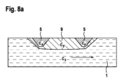
図8aは、本明細書に提示されるシステムの詳細図の概略図を示す。図8bは、本明細書に提示されるさらなるシステムの詳細図の概略図を示す。図8aおよび図8bは、以下において一緒に説明される。参照記号は一様に使用される。 Figure 8a shows a schematic diagram of a detailed view of the system presented herein. FIG. 8b shows a schematic diagram of further system details presented herein. Figures 8a and 8b are discussed together below. Reference symbols are used uniformly.
可能な限り最良の反射を得るには、反射体の表面は入射超音波波面と平行である必要がある。重ね合わされた反射体などの非平面表面は、流れの乱流(ドップラー超音波測定に不利な)、血栓の形成、およびせん断力による追加の血液損傷(溶血)につながる可能性があるため、図8aおよび8bに例証されるように、反射体5を埋め込み材料9に埋め込むのが好都合である。埋め込み材料9は、反射体表面と比較して、より滑らかな表面あるいは角および/またはエッジのない表面を提供するための例として、本明細書で使用される。特に、少なくとも一つの反射体5を、特に埋め込み材料9によって平面に埋め込むことが好ましい。埋め込み材料9は、この追加の回折が所望されない場合、音響インパルスの追加的な反射または回折がないように、流体1(ここでは血液)と同じ音響インピーダンスを可能な限り有し、また可能な限り薄くすべきである。例えば、音響インピーダンスC4を有するその反射体5(または各反射体5)は、音響インピーダンスC3’を有するシリコンに埋め込まれてもよく、そこでは、C3’は血液の音響インピーダンスC3と類似している。
For the best possible reflection, the surface of the reflector needs to be parallel to the incident ultrasound wavefront. Non-planar surfaces such as superimposed reflectors can lead to flow turbulence (disadvantageous for Doppler ultrasound measurements), thrombus formation, and additional blood damage (hemolysis) due to shear forces; It is advantageous to embed the
ここで特に説明するソリューションには、以下の利点のうちの一つ以上がある。
・超音波システムの放射範囲で少なくとも一つの超音波反射体を補足することによって、音速は、結果として生じるパルス飛行時間および/または反射体からのランプ飛行時間から決定することができる。
・既知の音速は、流量測定の測定精度を増加させる。
・音速は、血液の組成に依存し、この場合、直接決定して使用することができる。
・FMCWアプローチは、測定に非常に正確な時間差を必要としない。同等の周波数差を代わりに決定することができ、これにより技術的労力が大幅に減少する。
The solution specifically described here has one or more of the following advantages:
- By supplementing at least one ultrasound reflector in the radiation range of the ultrasound system, the speed of sound can be determined from the resulting pulse flight time and/or ramp flight time from the reflector.
- Known speed of sound increases measurement accuracy of flow measurements.
- The speed of sound depends on the composition of the blood and in this case can be determined and used directly.
- The FMCW approach does not require very precise time differences for measurements. An equivalent frequency difference can be determined instead, which significantly reduces the technical effort.
Claims (29)
a)前記血管補助システムが、超音波センサによって超音波信号を送信する工程と、
b)前記流体の流路に少なくとも部分的に突出し、前記超音波センサの視野に、且つ前記超音波センサから定義された距離で配置されている、少なくとも一つの音響反射体に、前記血管補助システムが前記超音波信号を反射させる工程と、
c)前記血管補助システムが、反射された前記超音波信号を受信する工程と、
d)前記血管補助システムが、評価ユニットによって前記反射された前記超音波信号に基づいて、前記流体中の前記音速を決定する工程と、を含む血管補助システムの作動を制御するための方法。 A method for controlling operation of a vascular assist system to determine the velocity of sound in a fluid within a portion of the vascular assist system, the method comprising:
a) the vascular assistance system transmits an ultrasound signal by an ultrasound sensor;
b) at least one acoustic reflector protruding at least partially into the fluid flow path and arranged in the field of view of the ultrasound sensor and at a defined distance from the ultrasound sensor; a system reflecting the ultrasound signal;
c) the vascular assist system receiving the reflected ultrasound signal;
d) a method for controlling the operation of a vascular assistance system, comprising the step of the vascular assistance system determining the sound velocity in the fluid based on the reflected ultrasound signal by an evaluation unit .
前記評価ユニットが、前記受信した反射された前記超音波信号を周波数変調アプローチに基づく評価アルゴリズムによって評価し、
前記評価アルゴリズムは、
前記超音波センサと前記少なくとも一つの音響反射体との前記定義された距離と、
前記超音波信号の周波数変化と、
ベースバンド時間信号のフーリエ変換により決定されたビート周波数と、の関数として流体中の前記音速を決定する、請求項1に記載の血管補助システムの作動を制御するための方法。 the evaluation unit modulates the frequency of the transmitted ultrasound signal;
the evaluation unit evaluates the received reflected ultrasound signal by an evaluation algorithm based on a frequency modulation approach;
The evaluation algorithm is
the defined distance between the ultrasonic sensor and the at least one acoustic reflector;
a frequency change of the ultrasound signal;
A method for controlling operation of a vascular assist system according to claim 1, wherein the speed of sound in a fluid is determined as a function of a beat frequency determined by a Fourier transform of a baseband time signal.
第1の音響反射体と、
少なくとも別の音響反射体であって、前記少なくとも別の音響反射体は、前記第1の音響反射体から定義された距離に配置され、且つ前記第1の音響反射体と前記少なくとも別の音響反射体とは前記超音波センサに対して異なる距離に配置されるように前記超音波センサの視野に配置されている少なくとも別の音響反射体と、を含む請求項1に記載の血管補助システムの作動を制御するための方法。 The at least one acoustic reflector is
a first acoustic reflector;
at least another acoustic reflector, the at least another acoustic reflector being disposed at a defined distance from the first acoustic reflector, and the first acoustic reflector and the at least another acoustic reflector being disposed at a defined distance from the first acoustic reflector; and at least another acoustic reflector disposed in the field of view of the ultrasonic sensor such that it is disposed at a different distance from the body to the ultrasonic sensor. A way to control .
前記血管補助システムが、前記少なくとも別の音響反射体で反射された前記超音波信号を受信する工程と、
前記血管補助システムが、前記評価ユニットによって前記反射された前記超音波信号を使用して、前記流体中の前記音速を決定する工程と、をさらに含み、
前記評価ユニットが、前記送信した超音波信号の周波数に周波数変調により影響を及ぼし、
前記評価ユニットが、前記受信した超音波信号を周波数変調アプローチに基づく評価アルゴリズムによって評価し、
前記評価アルゴリズムは、
前記第1の音響反射体との前記少なくとも別の音響反射体との前記定義された距離と、
前記超音波信号の周波数変化と、
第1の差周波数であって、ベースバンド時間信号のフーリエ変換により決定され、前記超音波センサから前記第1の音響反射体へ送信した超音波信号と、前記第1の音響反射体で反射し前記超音波センサにより受信した超音波信号との間の第1の差周波数と、
少なくとも一つの他の差周波数であって、ベースバンド時間信号のフーリエ変換により決定され、前記超音波センサから前記少なくとも別の音響反射体へ送信した超音波信号と、前記少なくとも別の音響反射体で反射し前記超音波センサにより受信した超音波信号との間の少なくとも一つの他の差周波数と、の関数として前記流体中の前記音速を決定する、請求項3に記載の血管補助システムの作動を制御するための方法。 the vascular assist system reflecting the ultrasound signal onto the at least another acoustic reflector;
the vascular assist system receiving the ultrasound signal reflected by the at least another acoustic reflector;
the vascular assistance system further comprising: using the reflected ultrasound signal by the evaluation unit to determine the speed of sound in the fluid;
the evaluation unit influences the frequency of the transmitted ultrasound signal by frequency modulation;
the evaluation unit evaluates the received ultrasound signal by an evaluation algorithm based on a frequency modulation approach;
The evaluation algorithm is
the defined distance between the first acoustic reflector and the at least another acoustic reflector;
a frequency change of the ultrasound signal;
A first difference frequency, which is determined by Fourier transform of a baseband time signal, between an ultrasonic signal transmitted from the ultrasonic sensor to the first acoustic reflector and reflected by the first acoustic reflector. a first difference frequency between the ultrasonic signal received by the ultrasonic sensor;
at least one other difference frequency determined by a Fourier transform of a baseband time signal between the ultrasound signal transmitted from the ultrasound sensor to the at least another acoustic reflector and the at least another acoustic reflector; and at least one other difference frequency between an ultrasound signal reflected and received by the ultrasound sensor. A way to control .
前記血管補助システム内またはその上に配置されて超音波信号を送信するように構成されている超音波センサと、
前記流体の流路に少なくとも部分的に突出し、前記超音波センサの視野に、且つ少なくとも前記超音波センサに対して定義された距離に配置され、前記超音波信号を反射するように構成されている少なくとも一つの音響反射体と、
反射した前記超音波信号に基づいて前記流体中の音速を決定するように構成されている評価ユニットと、を備える、流体中の音速を決定するシステム。 A system for determining the speed of sound in a fluid within a portion of a vascular assist system for controlling operation of the vascular assist system, the system comprising:
an ultrasound sensor disposed within or on the vascular assist system and configured to transmit an ultrasound signal ;
at least partially protruding into the fluid flow path, located in the field of view of the ultrasonic sensor and at least a defined distance relative to the ultrasonic sensor , and configured to reflect the ultrasonic signal. at least one acoustic reflector comprising:
an evaluation unit configured to determine the speed of sound in the fluid based on the reflected ultrasound signal.
前記超音波信号は、周波数変調により影響を及ぼすことができる、請求項14に記載の流体中の音速を決定するシステム。 The ultrasonic sensor is configured to receive the reflected ultrasonic signal, and
15. The system for determining the speed of sound in a fluid according to claim 14 , wherein the ultrasound signal can be influenced by frequency modulation.
前記評価アルゴリズムは、
前記超音波センサと前記少なくとも一つの音響反射体との前記定義された距離と、
前記超音波信号の周波数変化と、
差周波数であって、ベースバンド時間信号のフーリエ変換により決定され、前記超音波センサから前記少なくとも一つの音響反射体へ送信した超音波信号と、前記少なくとも一つの音響反射体で反射し前記超音波センサにより受信した超音波信号との間の差周波数と、の関数として前記流体中の前記音速を決定するように構成されている、請求項15に記載の流体中の音速を決定するシステム。 an evaluation algorithm based on a frequency modulation approach is stored in said evaluation unit;
The evaluation algorithm is
the defined distance between the ultrasonic sensor and the at least one acoustic reflector;
a frequency change of the ultrasound signal;
a difference frequency determined by Fourier transform of a baseband time signal between an ultrasound signal transmitted from the ultrasound sensor to the at least one acoustic reflector and the ultrasound signal reflected by the at least one acoustic reflector; 16. The system for determining the speed of sound in a fluid according to claim 15, configured to determine the speed of sound in the fluid as a function of a difference frequency between an ultrasound signal received by a sensor.
前記超音波センサの視野に配置されている第1の音響反射体と、
少なくとも別の音響反射体であって、前記少なくとも別の音響反射体は、前記第1の音響反射体から定義された距離に配置され、且つ前記第1の音響反射体と前記少なくとも別の音響反射体とは前記超音波センサに対して異なる距離に配置されるように前記超音波センサの視野に配置されている少なくとも別の音響反射体と、を含む、請求項16に記載の流体中の音速を決定するシステム。 The at least one acoustic reflector is
a first acoustic reflector disposed in the field of view of the ultrasonic sensor;
at least another acoustic reflector, the at least another acoustic reflector being disposed at a defined distance from the first acoustic reflector, and the first acoustic reflector and the at least another acoustic reflector being disposed at a defined distance from the first acoustic reflector; and at least another acoustic reflector located in the field of view of the ultrasound sensor such that the body is located at a different distance relative to the ultrasound sensor. system to determine.
前記第1の音響反射体と前記少なくとも別の音響反射体との前記定義された距離と、
前記超音波信号の周波数変化と、
第1の差周波数であって、ベースバンド時間信号のフーリエ変換により決定され、前記超音波センサから前記第1の音響反射体へ送信した超音波信号と、前記第1の音響反射体で反射し前記超音波センサにより受信した超音波信号との間の第1の差周波数と、
第2の差周波数であって、ベースバンド時間信号のフーリエ変換により決定され、前記超音波センサから前記少なくとも別の音響反射体へ送信した超音波信号と、前記少なくとも別の音響反射体で反射し前記超音波センサにより受信した超音波信号との間の第2の差周波数と、の関数として前記流体中の前記音速を決定するように構成されている、請求項18に記載の流体中の音速を決定するシステム。 The evaluation algorithm is
the defined distance between the first acoustic reflector and the at least another acoustic reflector;
a frequency change of the ultrasound signal;
A first difference frequency, which is determined by Fourier transform of a baseband time signal, between an ultrasonic signal transmitted from the ultrasonic sensor to the first acoustic reflector and reflected by the first acoustic reflector. a first difference frequency between the ultrasonic signal received by the ultrasonic sensor;
a second difference frequency determined by a Fourier transform of a baseband time signal between an ultrasound signal transmitted from the ultrasound sensor to the at least another acoustic reflector and reflected by the at least another acoustic reflector; and a second difference frequency between an ultrasonic signal received by the ultrasonic sensor and a second difference frequency between the ultrasonic signals received by the ultrasonic sensor. system to determine.
前記補助システム内またはその上に配置されて超音波信号を送信するように構成されている超音波センサと、
流体の流路に少なくとも部分的に突出し、前記超音波センサの視野に、且つ少なくとも前記超音波センサに対して定義された距離に配置され、前記超音波信号を反射するように構成されている少なくとも一つの音響反射体と、
反射した前記超音波信号に基づいて前記流体中の音速を決定するように構成されている評価ユニットと、を備える、血管補助システム。 A vascular assist system,
an ultrasonic sensor disposed within or on the auxiliary system and configured to transmit an ultrasonic signal ;
at least partially protruding into a fluid flow path, located in the field of view of the ultrasonic sensor and at least a defined distance relative to the ultrasonic sensor , and configured to reflect the ultrasonic signal. at least one acoustic reflector comprising:
an evaluation unit configured to determine the speed of sound in the fluid based on the reflected ultrasound signal.
Applications Claiming Priority (3)
| Application Number | Priority Date | Filing Date | Title |
|---|---|---|---|
| DE102018208899.3A DE102018208899A1 (en) | 2018-06-06 | 2018-06-06 | A method for determining the speed of sound in a fluid in the region of an implanted vascular support system |
| DE102018208899.3 | 2018-06-06 | ||
| PCT/EP2019/064803 WO2019234163A1 (en) | 2018-06-06 | 2019-06-06 | Method and system for determining the speed of sound in a fluid in the region of an implanted vascular support system |
Publications (3)
| Publication Number | Publication Date |
|---|---|
| JP2021526891A JP2021526891A (en) | 2021-10-11 |
| JPWO2019234163A5 JPWO2019234163A5 (en) | 2022-06-15 |
| JP7387180B2 true JP7387180B2 (en) | 2023-11-28 |
Family
ID=66794008
Family Applications (1)
| Application Number | Title | Priority Date | Filing Date |
|---|---|---|---|
| JP2020567974A Active JP7387180B2 (en) | 2018-06-06 | 2019-06-06 | Method and system for determining the velocity of sound in a fluid within the region of an implanted vascular assist system, and a vascular assist system using the same |
Country Status (6)
| Country | Link |
|---|---|
| US (1) | US20210339002A1 (en) |
| EP (1) | EP3801281A1 (en) |
| JP (1) | JP7387180B2 (en) |
| CN (1) | CN112533543A (en) |
| DE (1) | DE102018208899A1 (en) |
| WO (1) | WO2019234163A1 (en) |
Families Citing this family (4)
| Publication number | Priority date | Publication date | Assignee | Title |
|---|---|---|---|---|
| LU100993B1 (en) * | 2018-11-09 | 2020-05-11 | Visseiro Gmbh | SENSOR SURFACE |
| AU2021381515A1 (en) | 2020-11-20 | 2023-07-06 | Kardion Gmbh | Purgeless mechanical circulatory support system with magnetic drive |
| US20230173250A1 (en) | 2021-12-03 | 2023-06-08 | Kardion Gmbh | Cardiac pump with optical fiber for laser doppler |
| DE102023118223A1 (en) | 2022-07-11 | 2024-01-11 | Kardion Gmbh | LASER DOPPLER VELOCIMETERY FLOW MEASUREMENT |
Citations (6)
| Publication number | Priority date | Publication date | Assignee | Title |
|---|---|---|---|---|
| JP2001506140A (en) | 1994-10-24 | 2001-05-15 | トランソニック・システムズ・インコーポレイテッド | Cardiovascular measurements by sound velocity dilution |
| US20060122583A1 (en) | 2002-06-25 | 2006-06-08 | Glucon Inc | Method and apparatus for performing myocardial revascularization |
| US20070266778A1 (en) | 2003-11-26 | 2007-11-22 | Corey Francis S | Method and Apparatus for Ultrasonic Determination of Hematocrit and Hemoglobin Concentrations |
| US20120203476A1 (en) | 2011-02-08 | 2012-08-09 | Cosense, Inc | Apparatus and method for real time measurement of a constituent of blood to monitor blood volume |
| US20140296677A1 (en) | 2003-09-18 | 2014-10-02 | New Paradigm Concepts, LLC | Method of measuring total vascular hemoglobin mass |
| JP2015181800A (en) | 2014-03-25 | 2015-10-22 | テルモ株式会社 | Flow sensor, extracorporeal circulation apparatus having flow sensor and control method thereof |
Family Cites Families (15)
| Publication number | Priority date | Publication date | Assignee | Title |
|---|---|---|---|---|
| JPS62282284A (en) * | 1986-05-30 | 1987-12-08 | Tokyo Keiki Co Ltd | Method and apparatus for measuring distance by ultrasonic wave |
| US5685989A (en) * | 1994-09-16 | 1997-11-11 | Transonic Systems, Inc. | Method and apparatus to measure blood flow and recirculation in hemodialysis shunts |
| IL138073A0 (en) * | 2000-08-24 | 2001-10-31 | Glucon Inc | Photoacoustic assay and imaging system |
| US7559894B2 (en) * | 2003-09-18 | 2009-07-14 | New Paradigm Concepts, LLC | Multiparameter whole blood monitor and method |
| US20080133006A1 (en) * | 2006-10-27 | 2008-06-05 | Ventrassist Pty Ltd | Blood Pump With An Ultrasonic Transducer |
| JP5283888B2 (en) * | 2006-11-02 | 2013-09-04 | 株式会社東芝 | Ultrasonic diagnostic equipment |
| EP1987774A1 (en) * | 2007-05-03 | 2008-11-05 | BrainLAB AG | Measurement of sonographic acoustic velocity using a marker device |
| DE102008040266A1 (en) * | 2008-07-09 | 2010-01-14 | Biotronik Crm Patent Ag | Implantable measuring arrangement |
| WO2010131136A1 (en) * | 2009-05-13 | 2010-11-18 | Koninklijke Philips Electronics, N.V. | Ultrasonic blood flow doppler audio with pitch shifting |
| DE102009025464A1 (en) * | 2009-06-12 | 2011-01-27 | Technische Universität Dresden | Assembly for determining sonic speeds and distances in e.g. fluid media, using ultrasound of ultrasonic imaging system, has evaluation unit determining variable sonic speed by determining parameters of point reflector at various locations |
| DE112010002450B4 (en) * | 2009-06-12 | 2017-12-07 | Technische Universität Dresden | Arrangement and method for the combined determination of sound velocities and distances in media by means of ultrasound |
| TW201336478A (en) * | 2011-12-01 | 2013-09-16 | Maui Imaging Inc | Motion detection using ping-based and multiple aperture doppler ultrasound |
| DE102014213233A1 (en) * | 2014-07-08 | 2016-01-14 | Continental Automotive Gmbh | Device for determining a speed of sound of a sound signal in a fluid |
| EP3115755B1 (en) * | 2015-07-06 | 2022-02-16 | ABB Schweiz AG | System and method for measuring a speed of sound in a liquid or gaseous medium |
| US11944495B2 (en) * | 2017-05-31 | 2024-04-02 | Foundry Innovation & Research 1, Ltd. | Implantable ultrasonic vascular sensor |
-
2018
- 2018-06-06 DE DE102018208899.3A patent/DE102018208899A1/en active Pending
-
2019
- 2019-06-06 JP JP2020567974A patent/JP7387180B2/en active Active
- 2019-06-06 US US15/734,322 patent/US20210339002A1/en active Pending
- 2019-06-06 WO PCT/EP2019/064803 patent/WO2019234163A1/en active Search and Examination
- 2019-06-06 EP EP19729271.7A patent/EP3801281A1/en active Pending
- 2019-06-06 CN CN201980047180.XA patent/CN112533543A/en active Pending
Patent Citations (6)
| Publication number | Priority date | Publication date | Assignee | Title |
|---|---|---|---|---|
| JP2001506140A (en) | 1994-10-24 | 2001-05-15 | トランソニック・システムズ・インコーポレイテッド | Cardiovascular measurements by sound velocity dilution |
| US20060122583A1 (en) | 2002-06-25 | 2006-06-08 | Glucon Inc | Method and apparatus for performing myocardial revascularization |
| US20140296677A1 (en) | 2003-09-18 | 2014-10-02 | New Paradigm Concepts, LLC | Method of measuring total vascular hemoglobin mass |
| US20070266778A1 (en) | 2003-11-26 | 2007-11-22 | Corey Francis S | Method and Apparatus for Ultrasonic Determination of Hematocrit and Hemoglobin Concentrations |
| US20120203476A1 (en) | 2011-02-08 | 2012-08-09 | Cosense, Inc | Apparatus and method for real time measurement of a constituent of blood to monitor blood volume |
| JP2015181800A (en) | 2014-03-25 | 2015-10-22 | テルモ株式会社 | Flow sensor, extracorporeal circulation apparatus having flow sensor and control method thereof |
Also Published As
| Publication number | Publication date |
|---|---|
| DE102018208899A1 (en) | 2019-12-12 |
| CN112533543A (en) | 2021-03-19 |
| WO2019234163A1 (en) | 2019-12-12 |
| JP2021526891A (en) | 2021-10-11 |
| EP3801281A1 (en) | 2021-04-14 |
| US20210339002A1 (en) | 2021-11-04 |
Similar Documents
| Publication | Publication Date | Title |
|---|---|---|
| JP7387180B2 (en) | Method and system for determining the velocity of sound in a fluid within the region of an implanted vascular assist system, and a vascular assist system using the same | |
| Posada et al. | Staggered multiple-PRF ultrafast color Doppler | |
| US6544181B1 (en) | Method and apparatus for measuring volume flow and area for a dynamic orifice | |
| JP7405449B2 (en) | Method and system for determining fluid flow rate through an implanted vascular assist system | |
| Vilkomerson et al. | Finding the peak velocity in a flow from its Doppler spectrum | |
| JP7269667B2 (en) | Implanted Vascular Support System and Method of Determining Fluid Flow Rate Through Implantable Vascular Support System | |
| Newhouse et al. | Three-dimensional vector flow estimation using two transducers and spectral width | |
| Ricci et al. | An improved Doppler model for obtaining accurate maximum blood velocities | |
| JP2023085343A (en) | Interventional device positioning for ultrasound image plane | |
| WO2009031034A2 (en) | Methods and devices for estimating blood flow characteristics | |
| US20210346676A1 (en) | Method for determining a flow rate of a fluid flowing through an implanted vascular support system, and implantable vascular support system | |
| Wilhjelm et al. | Target velocity estimation with FM and PW echo ranging Doppler systems I. Signal analysis | |
| JP7299968B2 (en) | Interventional device positioning with respect to the ultrasound image plane | |
| JP2019523082A (en) | System and method for determining cardiac output | |
| Hoyos et al. | Adaptive multi-lag for synthetic aperture vector flow imaging | |
| Wang et al. | P6B-7 The initial doppler blood flow measurement using an implantable CMUT array | |
| Grall-Maës et al. | Ultrasonic Doppler measurement using a pseudo-continuous mode | |
| Steinman et al. | Beam steering in pulsed'Doppler'ultrasound velocity estimation | |
| JPH0564059B2 (en) | ||
| Abe et al. | 1J1-2 In vivo Estimation of Sound Velocity Distribution for Diagnosis of Chronic Liver Disease and High Resolution Ultrasonic Tomographic Imaging | |
| CN112566556A (en) | Tracking an interventional device relative to an ultrasound image plane | |
| de Ana et al. | Quantitative blood flow estimation error due to the in-plane component of the flow with intravascular ultrasound | |
| Shimaya et al. | P1D-2 Fundamental Study for IVUS based on Pulse Compression System | |
| CN115990035A (en) | Hemodynamic parameter measurement correction method and ultrasonic device | |
| Zhang et al. | A novel velocity estimator using multiple frequency carriers |
Legal Events
| Date | Code | Title | Description |
|---|---|---|---|
| A521 | Request for written amendment filed |
Free format text: JAPANESE INTERMEDIATE CODE: A523 Effective date: 20220606 |
|
| A621 | Written request for application examination |
Free format text: JAPANESE INTERMEDIATE CODE: A621 Effective date: 20220606 |
|
| A977 | Report on retrieval |
Free format text: JAPANESE INTERMEDIATE CODE: A971007 Effective date: 20230331 |
|
| A131 | Notification of reasons for refusal |
Free format text: JAPANESE INTERMEDIATE CODE: A131 Effective date: 20230404 |
|
| A521 | Request for written amendment filed |
Free format text: JAPANESE INTERMEDIATE CODE: A523 Effective date: 20230703 |
|
| A131 | Notification of reasons for refusal |
Free format text: JAPANESE INTERMEDIATE CODE: A131 Effective date: 20230718 |
|
| A521 | Request for written amendment filed |
Free format text: JAPANESE INTERMEDIATE CODE: A523 Effective date: 20231017 |
|
| TRDD | Decision of grant or rejection written | ||
| A01 | Written decision to grant a patent or to grant a registration (utility model) |
Free format text: JAPANESE INTERMEDIATE CODE: A01 Effective date: 20231031 |
|
| A61 | First payment of annual fees (during grant procedure) |
Free format text: JAPANESE INTERMEDIATE CODE: A61 Effective date: 20231108 |
|
| R150 | Certificate of patent or registration of utility model |
Ref document number: 7387180 Country of ref document: JP Free format text: JAPANESE INTERMEDIATE CODE: R150 |