JP7383420B2 - Image processing device, recording device, image processing method, and program - Google Patents
Image processing device, recording device, image processing method, and program Download PDFInfo
- Publication number
- JP7383420B2 JP7383420B2 JP2019147566A JP2019147566A JP7383420B2 JP 7383420 B2 JP7383420 B2 JP 7383420B2 JP 2019147566 A JP2019147566 A JP 2019147566A JP 2019147566 A JP2019147566 A JP 2019147566A JP 7383420 B2 JP7383420 B2 JP 7383420B2
- Authority
- JP
- Japan
- Prior art keywords
- image processing
- image data
- group
- groups
- recording
- Prior art date
- Legal status (The legal status is an assumption and is not a legal conclusion. Google has not performed a legal analysis and makes no representation as to the accuracy of the status listed.)
- Active
Links
- 238000012545 processing Methods 0.000 title claims description 378
- 238000003672 processing method Methods 0.000 title description 3
- 238000012546 transfer Methods 0.000 claims description 109
- 238000000034 method Methods 0.000 claims description 75
- 238000001514 detection method Methods 0.000 claims description 11
- 239000000976 ink Substances 0.000 description 57
- 230000008569 process Effects 0.000 description 51
- 239000003086 colorant Substances 0.000 description 27
- 208000028659 discharge Diseases 0.000 description 19
- 230000007246 mechanism Effects 0.000 description 16
- 230000002093 peripheral effect Effects 0.000 description 16
- 238000010586 diagram Methods 0.000 description 14
- 238000007689 inspection Methods 0.000 description 14
- 239000000463 material Substances 0.000 description 11
- 230000009467 reduction Effects 0.000 description 11
- 238000004891 communication Methods 0.000 description 10
- 238000001454 recorded image Methods 0.000 description 9
- 230000000295 complement effect Effects 0.000 description 8
- 239000007788 liquid Substances 0.000 description 8
- 230000006870 function Effects 0.000 description 7
- 238000012805 post-processing Methods 0.000 description 7
- 230000000694 effects Effects 0.000 description 5
- 238000010521 absorption reaction Methods 0.000 description 4
- 239000012295 chemical reaction liquid Substances 0.000 description 3
- 238000004140 cleaning Methods 0.000 description 3
- 238000004040 coloring Methods 0.000 description 3
- 238000010438 heat treatment Methods 0.000 description 3
- 230000004044 response Effects 0.000 description 3
- 238000011144 upstream manufacturing Methods 0.000 description 3
- 230000015572 biosynthetic process Effects 0.000 description 2
- 230000008859 change Effects 0.000 description 2
- 239000000049 pigment Substances 0.000 description 2
- 238000007781 pre-processing Methods 0.000 description 2
- 239000011347 resin Substances 0.000 description 2
- 229920005989 resin Polymers 0.000 description 2
- MKUXAQIIEYXACX-UHFFFAOYSA-N aciclovir Chemical compound N1C(N)=NC(=O)C2=C1N(COCCO)C=N2 MKUXAQIIEYXACX-UHFFFAOYSA-N 0.000 description 1
- 230000000740 bleeding effect Effects 0.000 description 1
- 238000009835 boiling Methods 0.000 description 1
- 238000012790 confirmation Methods 0.000 description 1
- 238000012937 correction Methods 0.000 description 1
- 230000003247 decreasing effect Effects 0.000 description 1
- 239000000428 dust Substances 0.000 description 1
- 239000004744 fabric Substances 0.000 description 1
- 239000003292 glue Substances 0.000 description 1
- 238000003384 imaging method Methods 0.000 description 1
- 239000011295 pitch Substances 0.000 description 1
- 239000002985 plastic film Substances 0.000 description 1
- 229920006255 plastic film Polymers 0.000 description 1
- 238000011084 recovery Methods 0.000 description 1
- 238000012360 testing method Methods 0.000 description 1
- XLYOFNOQVPJJNP-UHFFFAOYSA-N water Substances O XLYOFNOQVPJJNP-UHFFFAOYSA-N 0.000 description 1
Images


Classifications
-
- G—PHYSICS
- G06—COMPUTING; CALCULATING OR COUNTING
- G06F—ELECTRIC DIGITAL DATA PROCESSING
- G06F3/00—Input arrangements for transferring data to be processed into a form capable of being handled by the computer; Output arrangements for transferring data from processing unit to output unit, e.g. interface arrangements
- G06F3/12—Digital output to print unit, e.g. line printer, chain printer
- G06F3/1201—Dedicated interfaces to print systems
- G06F3/1202—Dedicated interfaces to print systems specifically adapted to achieve a particular effect
- G06F3/1211—Improving printing performance
- G06F3/1215—Improving printing performance achieving increased printing speed, i.e. reducing the time between printing start and printing end
-
- H—ELECTRICITY
- H04—ELECTRIC COMMUNICATION TECHNIQUE
- H04N—PICTORIAL COMMUNICATION, e.g. TELEVISION
- H04N1/00—Scanning, transmission or reproduction of documents or the like, e.g. facsimile transmission; Details thereof
- H04N1/23—Reproducing arrangements
-
- B—PERFORMING OPERATIONS; TRANSPORTING
- B41—PRINTING; LINING MACHINES; TYPEWRITERS; STAMPS
- B41J—TYPEWRITERS; SELECTIVE PRINTING MECHANISMS, i.e. MECHANISMS PRINTING OTHERWISE THAN FROM A FORME; CORRECTION OF TYPOGRAPHICAL ERRORS
- B41J29/00—Details of, or accessories for, typewriters or selective printing mechanisms not otherwise provided for
- B41J29/38—Drives, motors, controls or automatic cut-off devices for the entire printing mechanism
- B41J29/393—Devices for controlling or analysing the entire machine ; Controlling or analysing mechanical parameters involving printing of test patterns
-
- G—PHYSICS
- G06—COMPUTING; CALCULATING OR COUNTING
- G06F—ELECTRIC DIGITAL DATA PROCESSING
- G06F3/00—Input arrangements for transferring data to be processed into a form capable of being handled by the computer; Output arrangements for transferring data from processing unit to output unit, e.g. interface arrangements
- G06F3/12—Digital output to print unit, e.g. line printer, chain printer
- G06F3/1201—Dedicated interfaces to print systems
- G06F3/1202—Dedicated interfaces to print systems specifically adapted to achieve a particular effect
- G06F3/121—Facilitating exception or error detection and recovery, e.g. fault, media or consumables depleted
-
- G—PHYSICS
- G06—COMPUTING; CALCULATING OR COUNTING
- G06F—ELECTRIC DIGITAL DATA PROCESSING
- G06F3/00—Input arrangements for transferring data to be processed into a form capable of being handled by the computer; Output arrangements for transferring data from processing unit to output unit, e.g. interface arrangements
- G06F3/12—Digital output to print unit, e.g. line printer, chain printer
- G06F3/1201—Dedicated interfaces to print systems
- G06F3/1223—Dedicated interfaces to print systems specifically adapted to use a particular technique
- G06F3/1237—Print job management
- G06F3/124—Parallel printing or parallel ripping
-
- G—PHYSICS
- G06—COMPUTING; CALCULATING OR COUNTING
- G06F—ELECTRIC DIGITAL DATA PROCESSING
- G06F3/00—Input arrangements for transferring data to be processed into a form capable of being handled by the computer; Output arrangements for transferring data from processing unit to output unit, e.g. interface arrangements
- G06F3/12—Digital output to print unit, e.g. line printer, chain printer
- G06F3/1201—Dedicated interfaces to print systems
- G06F3/1278—Dedicated interfaces to print systems specifically adapted to adopt a particular infrastructure
- G06F3/1279—Controller construction, e.g. aspects of the interface hardware
-
- G—PHYSICS
- G06—COMPUTING; CALCULATING OR COUNTING
- G06F—ELECTRIC DIGITAL DATA PROCESSING
- G06F3/00—Input arrangements for transferring data to be processed into a form capable of being handled by the computer; Output arrangements for transferring data from processing unit to output unit, e.g. interface arrangements
- G06F3/12—Digital output to print unit, e.g. line printer, chain printer
- G06F3/1201—Dedicated interfaces to print systems
- G06F3/1278—Dedicated interfaces to print systems specifically adapted to adopt a particular infrastructure
- G06F3/1282—High volume printer device
-
- H—ELECTRICITY
- H04—ELECTRIC COMMUNICATION TECHNIQUE
- H04N—PICTORIAL COMMUNICATION, e.g. TELEVISION
- H04N1/00—Scanning, transmission or reproduction of documents or the like, e.g. facsimile transmission; Details thereof
- H04N1/00002—Diagnosis, testing or measuring; Detecting, analysing or monitoring not otherwise provided for
-
- B—PERFORMING OPERATIONS; TRANSPORTING
- B41—PRINTING; LINING MACHINES; TYPEWRITERS; STAMPS
- B41J—TYPEWRITERS; SELECTIVE PRINTING MECHANISMS, i.e. MECHANISMS PRINTING OTHERWISE THAN FROM A FORME; CORRECTION OF TYPOGRAPHICAL ERRORS
- B41J25/00—Actions or mechanisms not otherwise provided for
- B41J2025/008—Actions or mechanisms not otherwise provided for comprising a plurality of print heads placed around a drum
-
- Y—GENERAL TAGGING OF NEW TECHNOLOGICAL DEVELOPMENTS; GENERAL TAGGING OF CROSS-SECTIONAL TECHNOLOGIES SPANNING OVER SEVERAL SECTIONS OF THE IPC; TECHNICAL SUBJECTS COVERED BY FORMER USPC CROSS-REFERENCE ART COLLECTIONS [XRACs] AND DIGESTS
- Y02—TECHNOLOGIES OR APPLICATIONS FOR MITIGATION OR ADAPTATION AGAINST CLIMATE CHANGE
- Y02D—CLIMATE CHANGE MITIGATION TECHNOLOGIES IN INFORMATION AND COMMUNICATION TECHNOLOGIES [ICT], I.E. INFORMATION AND COMMUNICATION TECHNOLOGIES AIMING AT THE REDUCTION OF THEIR OWN ENERGY USE
- Y02D10/00—Energy efficient computing, e.g. low power processors, power management or thermal management
Description
本発明は、複数の画像処理モジュールを用いて画像処理を行う画像処理装置、記録装置、画像処理方法、及びプログラムに関する。 The present invention relates to an image processing device, a recording device, an image processing method, and a program that perform image processing using a plurality of image processing modules.
従来、画像処理の高速化を図る方法として、複数の処理部を直列あるいは並列に接続して分散処理する方法が知られている。特許文献2では、画像処理の処理性能を向上させるため、同一機能を持つ複数の画像処理モジュールをPCIeスイッチ等の画像データの取得部に接続し、各画像処理モジュールによって、画像データの並列処理を行う技術が開示されている。 Conventionally, as a method for speeding up image processing, a method is known in which a plurality of processing units are connected in series or in parallel to perform distributed processing. In Patent Document 2, in order to improve the processing performance of image processing, a plurality of image processing modules having the same function are connected to an image data acquisition unit such as a PCIe switch, and each image processing module performs parallel processing of image data. A technique for performing this is disclosed.
特許文献1の方法では、一つでも画像処理モジュールにエラーが発生すると処理全体が停止するという課題がある。
The method disclosed in
本発明は、複数のモジュールの中にエラーが発生した場合にも画像処理の継続することが可能な画像処理技術の提供を目的とする。 An object of the present invention is to provide an image processing technique that allows image processing to continue even when an error occurs in a plurality of modules.
本発明は、記録装置に供給する画像データを生成するための画像処理を行う画像処理装置であって、入力画像データを分割した分割画像データに所定の画像処理を施す複数のモジュールを備え、前記複数のモジュールそれぞれの処理後の画像データを、所定の前記モジュールを介して出力する画像処理グループと、複数の前記画像処理グループが並列に接続され、各々の前記画像処理グループから出力された処理後の画像データを取得する取得手段と、前記複数のモジュールのうち正常な処理が行われないエラーモジュールを検知する検知手段と、複数の前記画像処理グループの中で画像処理に使用することが可能な使用可能グループを前記検知手段が検知した結果に基づいて設定し、前記分割画像データの画像処理を前記使用可能グループに実行させる制御手段と、を備え、前記制御手段は、前記複数の画像処理グループのうち、前記取得手段に対して通信可能であり、かつ正常な画像処理を可能とする正常モジュールを少なくとも1つ備える画像処理グループを前記使用可能グループとして定め、前記使用可能グループに前記エラーモジュールが存在したとき、当該エラーモジュールが属する使用可能グループにおける前記正常モジュールのみによって前記分割画像データの画像処理を実行し、前記制御手段は、前記エラーモジュールが存在する前記使用可能グループの画像処理速度が、前記正常モジュールのみを備えた前記使用可能グループの画像処理速度と均等になるように、前記エラーモジュールが存在する使用可能グループによって処理すべき前記分割画像データのデータ量を定めることを特徴とする。 The present invention is an image processing device that performs image processing to generate image data to be supplied to a recording device, and includes a plurality of modules that perform predetermined image processing on divided image data obtained by dividing input image data. An image processing group that outputs image data processed by each of a plurality of modules via a predetermined module, and a plurality of image processing groups connected in parallel to output processed image data from each of the image processing groups. an acquisition means for acquiring image data of the plurality of image processing groups, a detection means for detecting an error module in which normal processing is not performed among the plurality of modules, and a detection means capable of being used for image processing among the plurality of image processing groups. control means for setting usable groups based on the results detected by the detection means and causing the usable groups to execute image processing of the divided image data; Among them, an image processing group that is capable of communicating with the acquisition means and includes at least one normal module that enables normal image processing is defined as the usable group, and the error module is included in the usable group. When the error module exists, the image processing of the divided image data is executed only by the normal module in the usable group to which the error module belongs, and the control means determines that the image processing speed of the usable group to which the error module exists is The data amount of the divided image data to be processed is determined according to the usable group in which the error module exists so that the image processing speed is equal to the image processing speed of the usable group that includes only the normal module. .
本発明によれば、本発明は、複数のモジュールの中にエラーが発生した場合にも画像処理の継続することが可能になる。 According to the present invention, it is possible to continue image processing even when an error occurs in a plurality of modules.
図面を参照して本発明の実施形態について説明する。なお、各図中、同一部分には同一符号を付す。 Embodiments of the present invention will be described with reference to the drawings. In each figure, the same parts are given the same reference numerals.
[記録装置]
図1は本発明の一実施形態に係る記録装置1を概略的に示した正面図である。本実施形態における記録装置1は、転写体40を介して記録媒体Pにインク像を転写することで記録物P’を製造する、枚葉式のインクジェットプリンタによって構成されている。記録装置1は、画像形成部1Aと、搬送部1Bとを含む。本実施形態では、X方向、Y方向、Z方向が、それぞれ、記録装置1の幅方向(全長方向)、奥行き方向、高さ方向を示している。記録媒体PはX方向に搬送される。
[Recording device]
FIG. 1 is a front view schematically showing a
本明細書において「記録」には、文字、図形等有意の情報を形成する場合のみならず、有意無意を問わず、広く記録媒体上に画像、模様、パターン等を形成する、又は媒体の加工を行う場合も含まれる。よって「記録」は、人間が視覚で知覚し得るように顕在化したものであるか否かを問わない。また、本実施形態では「記録媒体]としてシート状の用紙を想定する。よって、以下の説明では、記録媒体の給送を、「給紙」とも言う。また、記録媒体は、紙の他、布、プラスチック・フィルム等であってもよい。インクの成分については、特に限定はないが、本実施形態では、色材である顔料、水、樹脂を含む水性顔料インクを用いる場合を想定する。 In this specification, "recording" includes not only the formation of significant information such as characters and figures, but also the formation of images, patterns, patterns, etc. on a recording medium, whether significant or not, or the processing of the medium. This also includes cases where the Therefore, it does not matter whether or not a "record" has been manifested so that it can be visually perceived by a human being. Further, in this embodiment, a sheet of paper is assumed as the "recording medium." Therefore, in the following description, feeding of the recording medium is also referred to as "paper feeding." In addition to paper, the recording medium may be cloth, plastic film, or the like. There are no particular limitations on the components of the ink, but in this embodiment, it is assumed that an aqueous pigment ink containing coloring materials such as pigment, water, and resin is used.
(画像形成部)
画像形成部1Aは、記録ユニット3、転写ユニット4および周辺ユニット5A~5D、および、供給ユニット6を含む。
(Image forming section)
The
<記録ユニット>
図1および図2に示すように、記録ユニット(記録手段)3は、複数の記録ヘッド30と、キャリッジ31とを含む。図2は記録ユニット3の斜視図である。記録ヘッド30は、転写体40に液体インクを吐出し、転写体40上に記録画像としてインク像を形成する。
<Recording unit>
As shown in FIGS. 1 and 2, the recording unit (recording means) 3 includes a plurality of
本実施形態の場合、各記録ヘッド30は、Y方向に延設されたフルラインヘッドであり、使用可能な最大サイズの記録媒体の画像記録領域の幅分をカバーする範囲に吐出口が配列されている。記録ヘッド30は、その下面に、吐出口が形成されている吐出面を有している。吐出面は、微小隙間(例えば数mm)を介して転写体40の表面と対向している。本実施形態の場合、転写体40は円軌道上を循環的に移動する構成を有する。このため、複数の記録ヘッド30は、転写体40の中心から放射状に配置されている。
In the case of this embodiment, each
各吐出口内にはインクを吐出するための吐出エネルギー発生素子(以下、吐出素子ともいう)が設けられている。吐出素子は、例えば、吐出口内に圧力を発生させて吐出口内のインクを吐出させる素子である。吐出素子としては、例えば電気-熱変換体によりインクに膜沸騰を生じさせ気泡を形成することでインクを吐出する素子、電気-機械変換体(ピエゾ)によってインクを吐出する素子、静電気を利用してインクを吐出する素子(ヒータ)等が挙げられる。高速で高密度の記録の観点からは電気-熱変換体を利用した吐出素子を用いることが有効である。 An ejection energy generating element (hereinafter also referred to as an ejection element) for ejecting ink is provided in each ejection port. The ejection element is, for example, an element that generates pressure within the ejection port to eject ink within the ejection port. Examples of ejection elements include elements that eject ink by causing film boiling in the ink using an electro-thermal converter to form bubbles, elements that eject ink using an electro-mechanical converter (piezo), and elements that eject ink using electro-mechanical converters (piezo). An example of this is an element (heater) that ejects ink. From the viewpoint of high-speed, high-density recording, it is effective to use a discharge element using an electrothermal converter.
本実施形態の場合、記録ヘッド30は、9つ設けられている。各記録ヘッド30は、互いに異なる種類のインクを吐出する。異なる種類のインクとは、例えば、色材が異なるインクであり、イエローインク、マゼンタインク、シアンインク、ブラックインク等のインクである。1つの記録ヘッド30は1種類のインクを吐出するが、1つの記録ヘッド30が複数種類のインクを吐出する構成であってもよい。このように複数の記録ヘッド30を設けた場合、そのうちの一部が色材を含まないインク(例えば画質向上液)を吐出してもよい。
In this embodiment, nine
キャリッジ31は、複数の記録ヘッド30を支持する。各記録ヘッド30は、吐出面側の端部がキャリッジ31に固定されている。これにより、吐出面と転写体40との表面の隙間をより精密に維持することができる。キャリッジ31は、案内部材RLの案内によって、記録ヘッド30を搭載しつつ変位可能に構成されている。本実施形態の場合、案内部材RLは、Y方向に延設されたレール部材であり、X方向に離間して一対設けられている。キャリッジ31のX方向の各側部にはスライド部32が設けられている。スライド部32は案内部材RLと係合し、案内部材RLに沿ってY方向にスライドする。
The
<転写ユニット>
図1を参照して転写ユニット4について説明する。転写ユニット4は、転写胴41と圧胴42とを含む。これらの胴は、Y方向の回転軸周りに回転する回転体であり、円筒形状の外周面を有している。図1において、転写胴41および圧胴42の内側に示した円弧状の矢印は、これらの回転方向を示しており、転写胴41は時計回りに、圧胴42は反時計回りに回転する。
<Transfer unit>
The
転写胴41は、その外周面で転写体40を支持する支持体である。転写体40は、転写胴41の外周面上に、周方向に連続的にあるいは間欠的に設けられる。連続的に設けられる場合、転写体40は無端の帯状に形成される。間欠的に設けられる場合、転写体40は、有端の帯状をなす複数のセグメントに分けて形成される。各セグメントは転写胴41の外周面に等ピッチで円弧状に配置することができる。
The
転写胴41の回転により、転写体40は円軌道上を循環的に移動する。転写胴41の回転位相により、転写体40の位置は、吐出前処理領域R1、吐出領域R2、吐出後処理領域R3およびR4、転写領域R5、転写後処理領域R6に区別することができる。転写体40はこれらの領域を循環的に通過する。
As the
吐出前処理領域R1は、記録ユニット3によるインクの吐出前に転写体40に対する前処理を行う領域であり、周辺ユニット5Aによる処理が行われる領域である。本実施形態の場合、画質向上を図るための反応液が付与される。吐出領域R2は記録ユニット3が転写体40にインクを吐出してインク像を形成する領域である。吐出後処理領域R3およびR4はインクの吐出後にインク像に対する処理を行う処理領域である。吐出後処理領域R3は周辺ユニット5Bによる処理が行われる領域であり、吐出後処理領域R4は周辺ユニット5Cによる処理が行われる領域である。転写領域R5は転写ユニット4により転写体40上のインク像が記録媒体Pに転写される領域である。転写後処理領域R6は、転写後に転写体40に対する後処理を行う領域であり、周辺ユニット5Dによる処理が行われる領域である。
The ejection pre-processing area R1 is an area where pre-processing is performed on the
圧胴42は、その外周面が転写体40に圧接される。圧胴42の外周面には、記録媒体Pの先端部を保持するグリップ機構が少なくとも一つ設けられている。グリップ機構は圧胴42の周方向に離間して複数設けてもよい。記録媒体Pは圧胴42の外周面に密接して搬送されつつ、圧胴42と転写体40とのニップ部を通過するときに、転写体40上のインク像が転写される。
The
<周辺ユニット>
周辺ユニット5A~5Dは転写体40の周囲に配置されている。本実施形態の場合、周辺ユニット5A~5Dは、それぞれ付与ユニット、吸収ユニット、加熱ユニット、清掃ユニットである。
<Peripheral units>
The
付与ユニット5Aは、記録ユニット3によるインクの吐出前に、転写体40上に反応液を付与する機構である。反応液は、インクを高粘度化する成分を含有する液体である。吸収ユニット5Bは、転写前に、転写体40上のインク像から液体成分を吸収する機構である。インク像の液体成分を減少させることで、記録媒体Pに記録される画像のにじみ等を抑制することができる。吸収ユニット5Bは、例えば、インク像に接触してインク像の液体成分の量を減少させる液吸収部材を含む。
The
加熱ユニット5Cは、転写前に、転写体40上のインク像を加熱する機構である。インク像を加熱することで、インク像中の樹脂が溶融し、記録媒体Pへの転写性が向上する。清掃ユニット5Dは、転写後に転写体40上を清掃する機構である。清掃ユニット5Dは、転写体40上に残留したインクや、転写体40上のごみ等を除去する。
The
<供給ユニット>
供給ユニット6は、記録ユニット3の各記録ヘッド30にインクを供給する機構である。供給ユニット6はインクを貯留する貯留部TKを備える。貯留部TKは、メインタンクとサブタンクとによって構成されてもよい。各貯留部TKと各記録ヘッド30とは流路6aで連通し、貯留部TKから記録ヘッド30へインクが供給される。流路6aは、貯留部TKと記録ヘッド30との間でインクを循環させる流路であってもよく、供給ユニット6はインクを循環させるポンプ等を備えてもよい。
<Supply unit>
The supply unit 6 is a mechanism that supplies ink to each
<搬送部>
搬送部1Bは、積載部に積載された記録媒体Pを転写ユニット4へ給送する。転写ユニット4に給送された記録媒体Pに対して、インク像が転写される(すなわち、記録される)。その後、搬送部1Bは、インク像が転写された記録物P’を転写ユニット4から排出する。搬送部1Bは、給送ユニット(給送手段)7、複数の搬送胴8、8a、2つのスプロケット8b、チェーン8cおよび回収ユニット8dを含む。図1において、搬送部1Bにおける後述の搬送胴8、8a内に付した円弧状の矢印は、搬送胴8、8aの回転方向を示し、外側の矢印は記録媒体Pまたは記録物P’の搬送経路を示している。記録媒体Pは給送ユニット7から転写ユニット4へ搬送され、記録物P’は転写ユニット4から回収ユニット8dへ搬送される。給送ユニット7側を搬送方向で上流側と呼び、回収ユニット8d側を下流側と呼ぶ場合がある。
<Transport section>
The
給送ユニット7は、複数の記録媒体Pが積載される積載部を含むと共に、積載部から一枚ずつ記録媒体Pを、最上流の搬送胴8に給送する給送機構を含む。各搬送胴8、8aはY方向の回転軸周りに回転する回転体であり、円筒形状の外周面を有している。各搬送胴8、8aの外周面には、記録媒体P(または記録物P’)の先端部を保持するグリップ機構が少なくとも一つ設けられている。各グリップ機構は、隣接する搬送胴間で記録媒体Pが受け渡されるように、その把持動作および解除動作が制御される。
The feeding unit 7 includes a stacking section on which a plurality of recording media P are stacked, and also includes a feeding mechanism that feeds the recording media P one by one from the stacking section to the most
2つの搬送胴8aは、記録媒体Pの反転用の搬送胴である。記録媒体Pを両面記録する場合、表面への転写後に、圧胴42から下流側に隣接する搬送胴8へ記録媒体Pを渡さずに、搬送胴8aに渡す。記録媒体Pは、2つの搬送胴8aを経由して表裏が反転され、圧胴42の上流側の搬送胴8を経由して再び圧胴42へ渡される。これにより、記録媒体Pの裏面が転写胴41に面することになり、裏面にインク像が転写される。
The two
チェーン8cは、2つのスプロケット8b間に架け渡されている。2つのスプロケット8bのうち、一方は駆動スプロケットであり、他方は従動スプロケットである。駆動スプロケットの回転によりチェーン8cが循環的に走行する。チェーン8cには、その長手方向に離間して複数のグリップ機構が設けられている。グリップ機構は、記録物P’の端部を把持する。下流端に位置する搬送胴8からチェーン8cのグリップ機構に記録物P’が渡される。グリップ機構に把持された記録物P’はチェーン8cの走行により回収ユニット8dへ搬送され、把持が解除される。これにより記録物P’が回収ユニット8d内に積載される。
The
<後処理ユニット>
搬送装置1Bには、後処理ユニット10A、10Bが設けられている。後処理ユニット10A、10Bは転写ユニット4よりも下流側に配置され、記録物P’に対して後処理を行う機構である。後処理ユニット10Aは、記録物P’の表面に対する処理を行い、後処理ユニット10Bは、記録物P’の裏面に対する処理を行う。
<Post-processing unit>
The
<検査ユニット>
搬送装置1Bには、検査ユニット9A、9Bが設けられている。検査ユニット9A、9Bは転写ユニット4よりも下流側に配置され、記録物P’の検査を行う機構である。本実施形態の場合、検査ユニット9Aは、記録物P’に記録された画像を撮影する撮影装置であり、例えば、CCDセンサやCMOSセンサ等の撮像素子を含む。検査ユニット9Aは、連続的に行われる記録動作中に、記録画像を撮影する。検査ユニット9Aが撮影した画像に基づいて、記録画像の色味などの経時変化を確認し、画像データあるいは記録データの補正の可否を判断することができる。本実施形態の場合、検査ユニット9Aは、圧胴42の外周面に撮像範囲が設定されており、転写直後の記録画像を部分的に撮影可能に配置されている。検査ユニット9Aにより全ての記録画像の検査を行ってもよいし、所定数毎に検査を行ってもよい。
<Inspection unit>
The
本実施形態の場合、検査ユニット9Bも、記録物P’に記録された画像を撮影する撮影装置であり、例えば、CCDセンサやCMOSセンサ等の撮像素子を含む。検査ユニット9Bは、テスト記録動作において記録画像を撮影する。検査ユニット9Bは、記録画像の全体を撮影し、検査ユニット9Bが撮影した画像に基づいて、記録データに関する各種の補正の基本設定を行うことができる。本実施形態の場合、チェーン8cで搬送される記録物P’を撮影する位置に配置されている。検査ユニット9Bにより記録画像を撮影する場合、チェーン8cの走行を一時的に停止して、その全体を撮影する。検査ユニット9Bは、記録物P’上を走査するスキャナであってもよい。
In the case of the present embodiment, the
<制御ユニット>
次に、記録装置1の制御ユニット13について説明する。図3は記録装置1の制御ユニット13のハード構成を示すブロック図である。制御ユニット13は、上位装置(DFE(Digital Front End Processor))HC2に通信可能に接続されている。また、上位装置HC2はホスト装置HC1に通信可能に接続されている。
<Control unit>
Next, the
ホスト装置HC1では、記録画像の元になる原稿データが生成、あるいは保存される。ここでの原稿データは、例えば、文書ファイルや画像ファイル等の電子ファイルの形式で生成される。この原稿データは、上位装置HC2へ送信され、上位装置HC2では、受信した原稿データを制御ユニット13で利用可能なデータ形式(例えば、RGBで画像を表現するRGBデータ)に変換する。変換後のデータは、画像データとして上位装置HC2から制御ユニット13へ送信される。制御ユニット13は受信した画像データに基づき、記録動作を開始する。
The host device HC1 generates or stores document data that is the source of recorded images. The manuscript data here is generated in the form of an electronic file such as a document file or an image file, for example. This document data is transmitted to the host device HC2, and the host device HC2 converts the received document data into a data format that can be used by the control unit 13 (for example, RGB data that expresses an image in RGB). The converted data is transmitted from the host device HC2 to the
本実施形態の場合、制御ユニット13は、メインコントローラ13Aと、エンジンコントローラ13Bとに大別される。メインコントローラ13Aは、処理部131、記憶部132、操作部133、画像処理部134、通信I/F(インターフェース)135、バッファ136および通信I/F137を含む。なお、制御ユニット13は、本実施形態における記録装置の記録動作を制御する記録制御手段としての機能を果す。エンジンコントローラ13Bは、本実施形態の供給装置としての機能を果す。さらに、処理部131や記憶部132によって、画像処理装置1の各部を制御するためのコンピュータが構成されている。
In the case of this embodiment, the
処理部131は、CPU等のプロセッサである。処理部131は、記憶部132に記憶されたプログラムを実行し、メインコントローラ13A全体の制御を行う。記憶部132は、RAM、ROM、ハードディスク、SSD等の記憶デバイスである。記憶部132には、CPUが実行するプログラムや、データが格納される。また、記憶部132は、CPUが処理を実行する際に使用するワークエリアを提供する。操作部133は、例えば、タッチパネル、キーボード、マウス等の入力デバイスであり、ユーザの指示を受け付ける。
The
画像処理部134は、例えば画像処理プロセッサを有する電子回路である。バッファ136は、例えば、RAM、ハードディスクまたはSSDにより構成されている。I/F135は上位装置HC2との通信を行い、I/F137はメインコントローラ13Aとエンジンコントローラ13Bとの通信を行う。
The
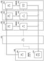
図4は、画像処理部134の構成を示すブロック図である。画像処理部134は画像処理コントローラ400、PCI Express(登録商標、以下PCIeとも記載する)スイッチ410、PCIeスイッチ411、及び画像処理を行う複数の画像処理モジュール(ASIC)420~445により構成される。画像処理コントローラ400には、画像処理を行う複数のASICがPCIeスイッチを介して接続されている。ここでは、複数のASICを接続するためのPCIeスロット数を確保するため、複数(図4では2個)のPCIeスイッチ410、411が画像処理コントローラ400に接続されている。画像処理コントローラ400は、種々の演算、制御を行う制御手段としての機能を有し、後述のASICにおけるメモリ容量の算出手段としての機能、及び記録速度もしくは記録可能速度を算出して取得する速度取得手段としての機能も果たす。さらに、画像処理コントローラ400とPCIeスイッチ410、411とにより、ASICへデータを送信する送信手段、及びASICからのデータを取得する取得手段を構成している。なお、本実施形態では画像処理装置134内の通信は全てPCIe通信であるが、これに限定するものでなく、USB、LAN等の性能を満たすものであれば、他の通信手段を用いてもよい。
FIG. 4 is a block diagram showing the configuration of the
以下、本実施形態の画像処理部134に設けられた複数のASICによって実行される画像処理の手順を説明する。図5は、複数のASICの接続状態、及び各ASICによるASICのグループ構成の一例を示す図である。本例では、3個のASICを直列に接続した画像処理グループ(以下、単にグループという)が、8個のグループa~hが設けられている。つまり、合計24個のASICが設けられている。8個のグループa~hのうち、4つのグループa~dがPCIeスイッチ410に接続され、他の4個のグループe~hがPCIe411に接続されている。
Hereinafter, a procedure of image processing executed by a plurality of ASICs provided in the
また、24個のASICは、PCIeスイッチに近い位置から順に、グループ(1)、グループ(2)、グループ(3)に分けられている。すなわちPCIeスイッチ410または411に接続されている8つのASICによってグループ(1)が構成されている。また、グループ(1)のASICに接続されている8つのASICによってグループ(2)が構成されている。さらに、グループ(2)のASICに接続されている8個のASICによってグループ(3)が構成されている。これら3個のグループ(1)~(3)は、それぞれ入力画像データに含まれる異なる色成分データの処理を行う。
Furthermore, the 24 ASICs are divided into group (1), group (2), and group (3) in order from the position closest to the PCIe switch. That is, group (1) is composed of eight ASICs connected to
また、本例では、入力画像データ500を24個のASICで分散して画像処理を行う。すなわち、形成すべき画像を8つの領域(以下、バンド領域ともいう)に分割し、入力画像データ500を、各領域に対応する8つの分割画像データ(以下、バンドデータとも言う)に分割する。各バンド領域に対応する分割画像データ(バンドデータ)の画像処理は、グループ(a)から(h)のそれぞれで担当する。バンドデータはさらに色分割され、グループ(1)から(3)に属するそれぞれのASICで所定の色成分データ毎に画像処理を行う。なお、具体的な処理については後述するが、グループ(1)ではCyan(C)とMagenta(M)の画像データが生成され、グループ(2)ではYellow(Y)とBlack(K)の画像データが生成される。さらに、グループ(3)ではLightCyan(Lc)とLightMagenta(Lm)とGray(Gy)の画像データが生成される。
Further, in this example,
以上のように、本例における画像処理部134に設けられたASIC群は、直列数3、並列数8の接続構成を有している。但し、ASIC群を構成するASICの数、直列数及び並列数は、図5に示す例に限定されない。処理する画像データのデータ量、色の種類などに限定されない。
As described above, the ASIC group provided in the
図6は、前述のグループ(a)~(h)の中の1つのグループにおけるデータの流れを示す図であり、画像処理コントローラ400から転送された入力画像データと、ASIC420、421、422によって処理された結果データが示されている。以下では、入力画像データをRGBデータ、結果データをCMYKLcLmGy(C:Cyan、M:Magenta、Y:Yellow、K:Black、Lc:LightCyan、Lm:LightMagenta、Gy:Gray)データとして説明する。
FIG. 6 is a diagram showing the flow of data in one of the groups (a) to (h) described above. Input image data transferred from the
画像処理コントローラ400には、上位装置HC2から転送されてきたRGB(R:Red、G:Green、B:Blue)データ600が保存されている。このRGBデータ600がPCIeスイッチ410を経由してASIC420に転送される。ASIC420は、転送されてきたRGBデータ600に対して画像処理を実施してCMデータ611を生成すると同時に、ASIC421にRGBデータ600を転送する。ASIC420はCMデータ611の生成を完了した後、PCIeスイッチ410を経由して画像処理コントローラ400に出力する。
The
ASIC421に転送されたRGBデータ600は、画像処理を実施してYKデータ612を生成すると同時に、ASIC422にRGBデータ600を転送する。ASIC421はYKデータ612の生成を完了した後、ASIC420に転送する。ASIC420は、ASIC421から転送されたYKデータ612を、PCIeスイッチ410を経由して画像処理コントローラ400に出力する。
The
ASIC422は、ASIC421から転送されたRGBデータ600に対して画像処理を実施し、LcLmGyデータ613を生成する。ASIC422はLcLmGyデータ613の生成を完了した後、LcLmGyデータ613をASIC421に転送する。ASIC421は転送されたLcLmGyデータ613をASIC420に転送する。ASIC420は転送されたLcLmGyデータ613を、PCIeスイッチ410を経由して画像処理コントローラ400に出力する。画像処理コントローラ400は、以上のようにしてASIC420から転送されてきたCMデータ611,YKデータ612,LcLmGyデータ613を統合してCMYKLcLmGyデータ610を生成する。
The
なお、ASIC420、ASIC421、ASIC422は、同一のバンド領域の色成分データを生成するものであるため、各ASICには、同一のRGBデータが入力される。例えば、ASIC420では、C、Mの2色、ASIC421ではY、Bの2色、ASIC422では、Lc、Lm、Gyの3色の色成分データをそれぞれ生成するが、これらは同一の画像を表現する色成分であるため、同一のRGBデータが入力される。
Note that since the
また、本実施形態では、RGBデータに対して画像処理を実施して、CM、YK、LcLmGyデータを生成する画像処理モジュールとして、ASIC(ASIC420、ASIC421、ASIC422)を用いた。しかし、CM、YK、LcLmGyデータを生成する画像処理モジュールは、ASICに限定されるものではない。FPGA(Field programmable Gate Array)やGPU(Graphics Processing Unit)等、画像処理可能なモジュールであれば他のモジュールを適用することも可能である。 Furthermore, in this embodiment, ASICs (ASIC420, ASIC421, ASIC422) are used as image processing modules that perform image processing on RGB data to generate CM, YK, and LcLmGy data. However, the image processing module that generates CM, YK, and LcLmGy data is not limited to ASIC. It is also possible to apply other modules as long as they are capable of image processing, such as FPGA (Field Programmable Gate Array) and GPU (Graphics Processing Unit).
また、ASIC420、ASIC421、ASIC422で生成する画像データの色、色数、及び色の組み合わせは、図6に示す例に限定されない。各ASICによって生成する画像データの色、色数、及び色の組み合わせを変更することも可能である。例えば、ASIC420でC,Kの2色の画像データを、ASIC421でY,M、Lmの3色の画像データを、ASIC422でLc,Gyの2色の画像データを、それぞれ生成するようにすることも可能である。さらに結果データに含まれる色は、C、M、Y、K、Lc、Lm、Gy以外にBlueであってもよく、各ASICで生成する画像データの色は、特に限定されない。
Furthermore, the colors, number of colors, and color combinations of the image data generated by the
本実施形態では、ASIC420、ASIC421、ASIC422の間で入力画像データ及び結果データを順次転送する、所謂バケツリレー方式で通信を行っている。しかし、ASIC420とASIC422とが直接通信を行ってもよく、特に通信方法は限定されない。
In this embodiment, communication is performed between
また、本実施形態では、グループ(1)、グループ(2)、グループ(3)の全3グループにて色分割を行い、並列処理を実施している。3グループとした理由は、画像処理装置として求められる画像処理速度を満たす最小限の構成だからである。求められる画像処理速度を満たすことが可能であれば、2グループでも良いし、4グループでもよく、特にグループ数は限定されない。 Further, in this embodiment, color division is performed in all three groups, group (1), group (2), and group (3), and parallel processing is performed. The reason for selecting three groups is that this is the minimum configuration that satisfies the image processing speed required for an image processing device. As long as it is possible to satisfy the required image processing speed, there may be two groups or four groups, and the number of groups is not particularly limited.
図7は、本実施形態における記録装置1における転写胴41及びその周辺部分を拡大して示す図である。転写胴41には、4つの円弧状の転写体401、402、403、404が取り付けられている。各転写体401~404の長さは同一に定められている。各転写体401~404には、記録ヘッド30(30C、30M、30Y、30K、30Lc、30Lm、30Gy、30I)から吐出されたインクが着弾し、画像が形成される。なお、記録ヘッド30Iは画像の品質を向上させるための画質向上液を吐出する記録ヘッドである。各転写体に形成された画像は、転写体401~404と、圧胴42との間を通過する用紙に転写される。本実施形態では、転写体401に対して用紙1枚分の画像が記録される。
FIG. 7 is an enlarged view showing the
記録速度の変更を行う場合、本実施形態の記録装置1では、転写胴41及び圧胴42の回転速度を変化させず、使用する転写体の数を変更する。例えば、4つの転写体401~404を使用し、各転写体に対して1枚ずつ用紙が供給されるタイミングで給紙を行う場合を最大の記録速度とする。これに対し、2つの転写体401と404のみを使用し、転写体401と404に対して1枚ずつ用紙が供給されるようなタイミングで給紙を行うことにより、最大の記録速度の2分の1の記録速度に変更することができる。さらに、転写体401のみを使用し、かつ転写体401にのみ1枚の用紙を給送するようなタイミングで給紙を行うことにより、記録速度を最大の記録速度の1/4に変更することができる。
When changing the recording speed, in the
このような方式によって記録速度の変更を行うことにより、各用紙への記録時間を一定に保つことができ、均一な画像品質を維持することが可能になる。但し、画像品質に大きな影響が生じない場合には、記録ヘッド30の駆動周波数、転写胴41及び圧胴42の回転速度を変化させることによって、記録速度を変更するようにすることも可能である。
By changing the recording speed using such a method, it is possible to keep the recording time on each sheet constant, and it is possible to maintain uniform image quality. However, if the image quality is not significantly affected, it is also possible to change the recording speed by changing the driving frequency of the
次に、画像処理部134を構成する画像処理ユニット発生時によって本実施形態において実行される画像処理方法を説明する。本実施形態では、図4に示すように、画像処理部134に設けられた複数(本例では24個)の画像処理モジュール(ASIC)のエラーを検知し、エラーが発生しているASICの位置・個数に応じた処理を行う。すなわち、画像処理エラーが発生したASICが存在していた場合に、グループa~hのうち、正常なASIC(正常モジュール)によって構成されるグループで画像処理を分担して画像データの生成を行う。
Next, an image processing method executed in this embodiment when an image processing unit forming the
エラー状態のASICがエラー状態にあるか否かは、初期化もしくは画像処理中に、各ASICに対してコマンドや処理要求等を送信できたか否かによって判断することができる。また、コマンドや処理要求等を送信した後一定時間応答がなかった時にも、ASICがエラー状態にあると判断することができる。具体的には、図4において、ASIC421からASIC422に対して初期化要求を送れなかった場合は、ASIC422がエラー状態にあると判断し、その旨を、ASIC420を経由して画像処理コントローラ400に通知する。画像処理コントローラ400は、ASIC422がエラー状態にあることをメモリに記録し、次回の画像処理時には、メモリに記録されている内容から、エラー状態にある画像処理モジュールを知ることが可能になる。
Whether or not an ASIC in an error state is in an error state can be determined by whether commands, processing requests, etc. can be sent to each ASIC during initialization or image processing. Furthermore, it can also be determined that the ASIC is in an error state when there is no response for a certain period of time after sending a command, processing request, etc. Specifically, in FIG. 4, if the
また、別の例としては、画像処理コントローラ400が、例えば、ASIC420に対して、初期化要求を送ったが一定時間応答がない場合がある。この場合にも、ASIC420にエラーが発生していると判断する。本実施形態では、ASIC420にエラーが発生している場合には、画像処理コントローラ400に対してASIC421及びASIC422が、直接通信しない構成となっている。従って、ASIC421及びASIC422に対して処理の要求を送ることが不可能となる。そのため、ASIC420にエラーが発生している場合、本実施形態では、ASIC421及びASIC422もエラー状態として扱い、画像処理コントローラ400のメモリに記録する。
Further, as another example, the
上記の説明では、コマンドや処理要求等を送信できなかった場合、もしくは送信した後に一定時間応答がなかった場合をエラーとして判断する例について述べた。しかし、画像処理後のCMYKLcLmGyデータのうち、特定の色の画像データが画像処理コントローラ400に送られて来ない場合に、その特定の色の処理を担当する画像処理モジュールにエラーが発生している、との判断を行うようにしてもよい。つまり、エラーの発生している画像処理モジュール(ASIC)を判定することができる方法であれば、いかなる方法も適用可能であり、その具体的な処理は特に限定されない。
In the above explanation, an example was described in which a case where a command, a processing request, etc. could not be sent, or a case where there was no response for a certain period of time after sending was determined to be an error. However, if image data of a specific color among the CMYKLcLmGy data after image processing is not sent to the
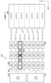
以下、図8及び図9を参照しつつ、本実施形態において実施される画像処理をより詳細に説明する。図8は画像処理部134に設けられている複数の画像処理モジュール(ASIC)のうち、ASIC427にエラーが発生し、その他の画像処理モジュールが正常な状態にある場合を示している。この場合、ASIC427と共に同一画像領域の処理を担当するグループc(斜線部801の中に示されるグループ)の使用を停止する。その他のグループaとグループb、及びグループd~グループhの合計7つのグループは、正常に画像処理を行うことが可能な正常グループである。よって、これら7つのグループを使用可能グループして定め、これらのグループにより分担して画像処理を行う。
The image processing performed in this embodiment will be described in more detail below with reference to FIGS. 8 and 9. FIG. 8 shows a case where an error occurs in the
図9は、本実施形態によって実行される画像処理の手順を示すフローチャートである。なお、本実施形態及びその他の実施形態で使用するフローチャートにおいて、各工程番号の前に付したSの文字は、ステップを意味している。処理部131からの画像処理の開始要求を受けると(S810)、エラー発生中の画像処理モジュール(ASIC)があるか否かの判定を行う(S811)。この判定は、前述のように、初期化もしくは既に実行された画像処理中に、エラー発生状態にあると判定されたASICの有無、及びエラー状態のASICの位置を、画像処理コントローラ400のメモリに記録された内容を確認することによって行う。
FIG. 9 is a flowchart showing the procedure of image processing performed by this embodiment. In addition, in the flowcharts used in this embodiment and other embodiments, the letter S added before each process number means a step. When a request to start image processing is received from the processing unit 131 (S810), it is determined whether there is an image processing module (ASIC) in which an error is occurring (S811). As described above, this determination involves storing the presence or absence of an ASIC determined to be in an error state and the location of the ASIC in an error state in the memory of the
S811においてエラー発生中のASICが存在しないと判定した場合には、画像処理を正常に行うことが可能な正常グループの数Nとして、全グループ数(図8に示す例では、「8」)を設定する(S821)。次にS815では、記録ヘッドの不吐ノズルを補完するために設けられた不吐補間ルックアップテーブル(以下、不吐補間LUT)を、正常グループ数N(=8)で分割する。そして、N分割した不吐補間LUTを、対応する各正常グループに転送する(S816)。 If it is determined in S811 that there is no ASIC in which an error has occurred, the total number of groups (in the example shown in FIG. 8, "8") is set as the number N of normal groups that can perform image processing normally. Set (S821). Next, in S815, the ejection failure interpolation lookup table (hereinafter referred to as ejection failure interpolation LUT) provided to complement the ejection failure nozzles of the print head is divided by the number of normal groups N (=8). Then, the N-divided discharge failure interpolation LUT is transferred to each corresponding normal group (S816).
次にS817では、各バンド数に対応させて入力画像データをN分割(8分割)し、その分割画像データを各正常グループに転送する(S818)。その後、各正常グループの各ASICにおいて画像処理を実行し(S819)、全てのASICで処理が終了したところで、一連の処理を終了する(S820)。 Next, in S817, the input image data is divided into N (divided into 8) corresponding to each number of bands, and the divided image data is transferred to each normal group (S818). Thereafter, image processing is executed in each ASIC of each normal group (S819), and when the processing is completed in all ASICs, the series of processing ends (S820).
一方、S811において、エラー状態のASICが存在すると判定された場合には、そのASICが存在するグループ以外のグループ(正常グループ)の数Nを設定する(S812)。次にS813では、S812で設定した正常グループ数が「0)であるか否かを確認する。ここで、正常グループ数が「0」であると判定した場合には、S825へ移行してエラーを通知し、一連の処理を終了する(S820)。 On the other hand, if it is determined in S811 that there is an ASIC in an error state, the number N of groups (normal groups) other than the group in which the ASIC exists is set (S812). Next, in S813, it is confirmed whether or not the number of normal groups set in S812 is "0".If it is determined that the number of normal groups is "0", the process moves to S825 and an error occurs. is notified, and the series of processing ends (S820).
またS813において、正常グループ数が「0」でないと判定した場合はS814へ移行し、画像処理部134によって行う処理速度の判定処理を行う。記録動作を行うために必要とされる画像処理速度(必要処理速度)以上であるかを判定する(S814)。具体的には、転写胴41が基準速度で回転するとき、先行する転写体への記録開始タイミングから、次の転写体への記録開始タイミングまでの時間内に、1枚の用紙に記録するための画像データの画像処理が完了するような画像処理速度以上であるかを判定する。つまり、ここで言う必要処理速度とは、基準速度で回転する転写胴41に設けられた4つの転写体401~403のそれぞれに連続的に画像を記録することを可能とする画像処理速度を意味する。
If it is determined in S813 that the number of normal groups is not "0", the process moves to S814, and the
S814の判定の結果、画像処理速度が必要処理速度以上であると判定された場合(YESである)と判定された場合には、正常なグループの数Nを分割数として設定し、前述のS815~S820の処理を行う。図8に示す例であれば、使用するグループ数Nを「7」に設定する。本実施形態の場合、使用するグループ数が「7」であれば、使用するグループ数が「8」の場合と同様の記録速度を得ることができる。すなわち、4つの転写体401~404に連続的に記録を行うことが可能である。このため、S814以降は、前述のS815~S820の処理を行う。
As a result of the determination in S814, if it is determined that the image processing speed is equal to or higher than the required processing speed (YES), the number N of normal groups is set as the number of divisions, and the process described in S815 is performed. ~ Perform the processing of S820. In the example shown in FIG. 8, the number N of groups to be used is set to "7". In the case of this embodiment, if the number of groups used is "7", the same recording speed as when the number of groups used is "8" can be obtained. That is, it is possible to perform continuous recording on the four
また、S812において設定された正常なグループ数Nが「6」であり、分割数が「6」に設定された場合、本実施形態では、画像処理速度が必要処理速度を下回る。このためS814からS822へと処理が移行する。S822では、現在設定されている記録速度を低下させることが許容されるか否かの確認を行う。確認方法は特に限定されない。例えば、事前に設定されていた記録速度の許容範囲を参照してもよいし、このタイミングでUIを通してユーザに確認してもよい。そして、記録速度の低下が許容されない場合には、S825のエラー通知を行い、処理を終了する(S820)。また、記録速度の低下が許容される場合には、現在の画像処理速度によって記録可能な速度を計算により取得し(S823)、取得した記録速度に応じて使用する転写体の選択を行うと共に、給紙タイミングの変更を行う(S824)。 Further, in the case where the normal number of groups N set in S812 is "6" and the number of divisions is set to "6", in this embodiment, the image processing speed is lower than the required processing speed. Therefore, the process moves from S814 to S822. In S822, it is checked whether it is permissible to reduce the currently set recording speed. The confirmation method is not particularly limited. For example, the permissible recording speed range that has been set in advance may be referred to, or the user may be asked to confirm this through the UI at this timing. If the decrease in recording speed is not allowed, an error notification in S825 is given, and the process ends (S820). In addition, if a decrease in the recording speed is allowed, the printable speed is calculated based on the current image processing speed (S823), and the transfer body to be used is selected according to the acquired recording speed. The paper feeding timing is changed (S824).
正常なグループ数が6の場合、本実施形態においては4つの転写体401~404のうち、2つの転写体401と403、または転写体402と404を用いる。さらに、給紙は2回に1回のタイミングで行う。これにより、全体的な記録速度は、分割数が「8」に設定された場合に対して2分の1となる。その後は、分割数Nを6として、S815~S820の処理を行う。
When the normal number of groups is 6, in this embodiment, out of the four
以上のように、本実施形態では、複数の画像処理モジュール(ASIC)の中にエラーが発生した場合、エラーの発生したASICを含むグループ以外の正常なグループに、画像データの処理を分配して処理を行う。このため、画像処理が停止することによって記録動作が停止することはなくなり、良好なスループットを得ることができる。 As described above, in this embodiment, when an error occurs in multiple image processing modules (ASICs), image data processing is distributed to a normal group other than the group containing the ASIC in which the error occurred. Perform processing. Therefore, the recording operation does not stop due to the stop of image processing, and good throughput can be obtained.
また、本実施形態では、処理モジュールの並列化及び直列化両方の手段を取り入れたハイブリットな構成を有している。このため、データ線の増大、及びデータの取得手段を構成するPCIeスイッチ410、411のポート数の増大を抑制することが可能になる。このため、並列処理より処理の高速化を図りつつ回路規模の増大を抑制することが可能になる。 Furthermore, this embodiment has a hybrid configuration that incorporates means for both parallelization and serialization of processing modules. Therefore, it is possible to suppress an increase in the number of data lines and an increase in the number of ports of the PCIe switches 410 and 411 that constitute the data acquisition means. Therefore, it is possible to achieve higher processing speed than parallel processing while suppressing an increase in circuit scale.
[第2実施形態]
次に、本発明の第2実施形態を、図10及び図11を参照しつつ説明する。なお、本実施形態においても、図1ないし図6の構成を同様に備えるものとする。本実施形態では、上記第1実施形態と同様に、エラーの発生していない画像処理モジュール(ASIC)からなる正常グループで画像処理を分担する。但し、正常なグループが少なく、画像処理を行うASICのメモリが不足する場合もある。本実施形態では、このような場合に対応する処理を実施する。
[Second embodiment]
Next, a second embodiment of the present invention will be described with reference to FIGS. 10 and 11. Note that this embodiment also includes the configurations shown in FIGS. 1 to 6. In this embodiment, as in the first embodiment, image processing is shared among a normal group consisting of image processing modules (ASICs) in which no errors have occurred. However, there may be cases where the number of normal groups is small and the memory of the ASIC that performs image processing is insufficient. In this embodiment, processing corresponding to such a case is performed.
図10は、画像処理モジュール(ASIC)425、427、429、436、441にエラーが発生し、その他の画像処理モジュールが正常な状態にある例を示している。本例の場合、エラー状態にあるASIC425、427、429、436、441を含むグループb、c、e、f、h(斜線部920、921、922に位置するグループ)の使用を停止する。そして、画像処理時には、正常なグループa、d、gの合計3個のグループに分担して画像処理を行う。本例のように、正常なグループ数が少ない場合、正常なグループ内の各ASICに設けられたメモリのサイズ(記憶容量)が、当該メモリの使用量に対して不足することがある。
FIG. 10 shows an example in which an error occurs in image processing modules (ASICs) 425, 427 , 429 , 436, and 441, and other image processing modules are in a normal state. In this example, the use of groups b, c, e, f, and h (groups located in the shaded
図11は、本実施形態によって実施される画像処理の手順を示すフローチャートである。図11において、S910~S913及びS915において実施する処理は、第1実施形態におけるS810~S813及びS821において実施する処理と同様であり、これらの処理についての重複説明は省略する。 FIG. 11 is a flowchart showing the procedure of image processing performed by this embodiment. In FIG. 11, the processes performed in S910 to S913 and S915 are the same as the processes performed in S810 to S813 and S821 in the first embodiment, and a redundant explanation of these processes will be omitted.
S913において正常グループ数が「0」でないと判定した場合には、各正常グループ内の各ASICに設けられたメモリの使用量がメモリサイズを超過したかを判定する(S914)。ここで、メモリ使用量が、当該メモリのサイズを超過していないときは、使用グループ数Nを正常グループ数とした状態を維持したまま、画像処理部134における画像処理速度が必要処理速度以上であるかを判定する(S917)。この判定処理は、第1実施形態において説明したS814の処理と同様である。
If it is determined in S913 that the number of normal groups is not "0", it is determined whether the amount of memory used in each ASIC in each normal group exceeds the memory size (S914). Here, if the memory usage does not exceed the size of the memory concerned, the image processing speed in the
一方、S914において、ASICのメモリサイズをメモリ使用量が超過すると判定した場合は、Nを全グループ数(本例では「8」)に設定し(S916)、S917へ移行する。なお、各ASICのメモリのサイズは、入力画像データを全グループ数で分割した場合のメモリ使用量以上に予め定められている。 On the other hand, if it is determined in S914 that the memory usage exceeds the memory size of the ASIC, N is set to the total number of groups ("8" in this example) (S916), and the process moves to S917. Note that the memory size of each ASIC is predetermined to be larger than the amount of memory used when input image data is divided by the total number of groups.
S917において、画像処理部134の処理速度が必要処理速度を上回ると判定した場合(YESの場合)には、図10に示す入力画像データ900及び不吐補完LUTをN分割(8分割)する(S918、S919)。その後、S920及びS921において、画像処理が行われていない未処理の画像データ901と当該画像データに対応する不吐補完LUT901を、正常なグループa、d、gに転送する。次にS922では、転送された不吐補完LUTを使用して未処理の画像データ901に対する画像処理を実施する。この後、S923では画像データ全体の処理が終了したか否かを確認する。図10に示すように、3つのバンドデータ(分割画像データ)901を処理した時点では、画像データ902及び画像データ903が未処理の状態にある。このため、S920に戻ってS920~923の処理を繰り返し、図10に示す未処理のバンドデータ902及び903の画像処理を行う。この後、画像データ901~903の処理が全て完了した時点で、一連の処理が終了する(S923、S924)。
In S917, if it is determined that the processing speed of the
図10の例に示すような正常なグループが3つの状態では、処理速度が必要処理速度を下回る可能性が高い。つまり、S916においてNOと判定される可能性が高い。処理速度が必要処理速度を下回ると判定された場合には、現在設定されている記録速度を低下させることが許容されるか否かを確認する処理を行う(S925)。ここで、記録速度を低下させることが許容されない場合には、エラーを通知する処理を行い(S928)、一連の処理を終了(S924)。これに対し、記録速度の低下が許容される場合には、画像処理速度に応じて低下させるべき記録速度を計算し(S926)、使用する転写体の選択を行うと共に、給紙タイミングの変更を行う(S927)。 In a state where there are three normal groups as shown in the example of FIG. 10, there is a high possibility that the processing speed will be lower than the required processing speed. In other words, there is a high possibility that the determination in S916 will be NO. If it is determined that the processing speed is lower than the required processing speed , a process is performed to confirm whether or not it is permissible to reduce the currently set recording speed (S925). If it is not permissible to reduce the recording speed, an error notification process is performed (S928), and the series of processes ends (S924). On the other hand, if a decrease in the recording speed is allowed, the recording speed to be decreased is calculated according to the image processing speed (S926), the transfer body to be used is selected, and the paper feeding timing is changed. Execute (S927).
正常なグループ数が「3」の場合、4つの転写体401~404のうち、1つの転写体を用い、給紙を4回に1回のタイミングで行う。これにより、全体的な記録速度は4分の1となる。その後は前述した、S918~S923の処理を行う。
When the normal number of groups is "3", one of the four
以上のように、本実施形態では、正常なグループが少なく、画像処理を行うASICのメモリが不足する場合にも、全ての画像データに対する処理を実施することが可能になり、記録動作を継続的に実施することができる。これにより、良好なスループットを得ることができる。また、装置の小型化、配線の削減、及びPCIeスイッチ410、411のポート数の低減などの効果も第1実施形態と同様に得られる。 As described above, in this embodiment, even when the number of normal groups is small and the memory of the ASIC that performs image processing is insufficient, it is possible to perform processing on all image data, and the recording operation can be performed continuously. can be implemented. Thereby, good throughput can be obtained. Furthermore, effects such as miniaturization of the device, reduction in wiring, and reduction in the number of ports of the PCIe switches 410 and 411 can be obtained in the same manner as in the first embodiment.
[第3実施形態]
次に、本発明の第3実施形態を、図12及び図13を参照しつつ説明する。なお、本実施形態においても、図1ないし図6の構成を同様に備えるものとする。本実施形態は、小サイズの用紙を用いる場合に好適な処理を行う。使用する用紙が小サイズの場合、本実施形態では、画像処理部134に設けられている複数の画像処理モジュール(ASIC)のうち、一部のASICを使用することで画像データの処理を実施することが可能である。例えば、A3の用紙を用いて記録を行う場合には、図12に示すように、画像処理部134のうちグループc~fまでの4グループを用いることで必要処理速度を達成することが可能である。但し、図12に示す例では、ACIC427にエラーが発生した状態を示している。この場合、画像処理ではASIC427を含むグループcは使用しない。
[Third embodiment]
Next, a third embodiment of the present invention will be described with reference to FIGS. 12 and 13. Note that this embodiment also includes the configurations shown in FIGS. 1 to 6. This embodiment performs suitable processing when using small-sized paper. When the paper to be used is small in size, in this embodiment, image data is processed by using some ASICs among the plurality of image processing modules (ASICs) provided in the
図13は、本実施形態における画像処理の手順を示すフローチャートである。画像処処理開始の要求を受けると(S1050)、使用グループ数Mと、正常グループ数Nを設定する(S1051)。図12に示す例では、使用グループ数Mを4、正常グループ数Nを7に設定する。ここで、使用グループ数Mと正常グループ数Nとの比較を行い、正常グループ数Nが使用グループ数M以上であれば、S1053へ移行してLを全グループ数とする。次いで、S1054において、正常グループの中から使用するグループを選択する。 FIG. 13 is a flowchart showing the procedure of image processing in this embodiment. When receiving a request to start image processing (S1050), the number M of used groups and the number N of normal groups are set (S1051). In the example shown in FIG. 12, the number M of used groups is set to 4, and the number N of normal groups is set to 7. Here, the number M of used groups is compared with the number N of normal groups, and if the number N of normal groups is greater than or equal to the number M of used groups, the process moves to S1053 and L is set as the total number of groups. Next, in S1054, a group to be used is selected from among the normal groups.
本例では、グループb、及びグループd~fを選択する。この後、先に設定した全グループ数L(本例ではL=8)で不吐補間LUTを分割し(S1055)、選択した使用グループのそれぞれに対し、対応する不吐補間LUTを転送する(S1056)。また、S1057において画像データを、使用グループ数M(本例ではM=4)で分割し(S1057)、選択した使用グループのそれぞれに対し、対応する分割画像データを転送する。その後、各使用グループにおいて画像データに対する画像処理を実施し、一連の処理を終了する(S1060)。 In this example, group b and groups d to f are selected. After that, the discharge failure interpolation LUT is divided by the total number of groups L set previously (L=8 in this example) (S1055), and the corresponding discharge failure interpolation LUT is transferred to each of the selected use groups ( S1056). Further, in S1057, the image data is divided by the number of usage groups M (M=4 in this example) (S1057), and the corresponding divided image data is transferred to each of the selected usage groups. Thereafter, image processing is performed on the image data in each usage group, and the series of processing ends (S1060).
一方、S1052において、正常グループ数Nが使用グループ数Mより少ないと判定した場合には、正常グループが「0」であるか否かの判定を行う(S1061)。判定の結果、正常なグループが「0」である場合にはエラーを通知し(S1070)、処理を終了する(S1060)。また、正常グループが「0」でないと判定した場合には、S1062において画像処理部134の処理速度が、記録動作を行うために必要とされる処理速度(必要処理速度)以上であるかを判定する。ここで、処理速度が必要処理速度以上であると判定した場合には、不吐補間LUTの中で必要な領域及び画像データをN分割する(S1063、S1064)。本例では処理速度が必要処理速度以上となるため、不吐補間LUT及び画像データをN分割(4分割)する(S1063、S1064)。そして、分割した不吐補間LUT及び画像データを正常グループのそれぞれに転送する(S1065、S1066)。その後、不吐補間LUTを使用して画像データの画像処理を正常グループの各正常モジュールで実施し、一連の処理を終了する(S1060)。
On the other hand, if it is determined in S1052 that the number N of normal groups is less than the number M of used groups, it is determined whether the number of normal groups is "0" (S1061). As a result of the determination, if the number of normal groups is "0", an error is notified (S1070) and the process ends (S1060). If it is determined that the normal group is not "0", it is determined in S1062 whether the processing speed of the
また、使用グループ数Mが正常グループ数Nより多く、正常グループ数Nが少数である場合、例えば、正常グループ数が「2」である場合には、画像処理部134の処理速度が必要処理速度を下回る可能性が高い。このように処理速度が必要処理速度を下回る場合には、記録速度を低下させることが許容されるか否かを確認する(S1062)。ここで、記録速度を低下させることが許容されない場合には、S1070でエラーを通知した後、一連の処理を終了する(S1060)。また、記録速度の低下が許容される場合には、現在の処理速度と必要処理速度とに基づき、記録を行うことが可能な速度(記録可能速度)を計算により取得する(S1068)。さらに、取得した記録可能速度に基づいて使用する転写体の選択と、給紙タイミングの変更を行う(S1069)。正常グループ数が「2」の場合、使用する転写体は4つのうち2つを選択し、給紙は2回に1回のタイミングで行う。これにより、全体的な記録速度は2分の1となる。その後はS1063~S1066の処理を経てS1059の画像処理を行い、一連の処理を終了する(S1060)。
In addition, when the number of used groups M is larger than the number of normal groups N, and the number of normal groups N is small, for example, when the number of normal groups is "2", the processing speed of the
以上のように、本実施形態によれば、第1または第2の実施形態と同様に、装置の小型化、配線の削減、及びPCIeスイッチ410、411のポート数の低減などの効果を得ることができる。さらに、小サイズの用紙を使用する際には、エラーが発生した画像処理モジュール(ASIC)を含むグループの使用を避けて、正常なグループのみを用いて継続的に画像処理を実施することが可能になる。このため、複数の記録媒体に対する記録動作を連続的に実施することが可能になり、スループットの向上を図ることができる。 As described above, according to the present embodiment, similar to the first or second embodiment, effects such as miniaturization of the device, reduction in wiring, and reduction in the number of ports of the PCIe switches 410 and 411 can be obtained. Can be done. Furthermore, when using small-sized paper, it is possible to avoid using the group that includes the image processing module (ASIC) in which an error has occurred, and continue image processing using only the normal group. become. Therefore, it becomes possible to continuously perform recording operations on a plurality of recording media, and it is possible to improve throughput.
[第4実施形態]
次に、本発明の第4実施形態を、図14及び図15を参照しつつ説明する。なお、本実施形態においても、図1ないし図6の構成を同様に備えるものとする。本実施形態における記録装置1は、図1及び図2に示すように、7色のインクを用いて画像を形成することが可能な構成を有する。しかし、記録モードには、7色のインク全てを用いず、使用するインク色を制限して画像を記録することも可能である。本実施形態では、このように使用するインク色を制限して記録を行う場合に好適な処理を行う。
[Fourth embodiment]
Next, a fourth embodiment of the present invention will be described with reference to FIGS. 14 and 15. Note that this embodiment also includes the configurations shown in FIGS. 1 to 6. As shown in FIGS. 1 and 2, the
使用するインクを4色に制限して記録を行うモードを設定した場合、処理を行う色数が少ないため、図14に示すように、斜線が付された領域1104の中に位置する画像処理モジュール(ASIC)のみを使用する。すなわち、グループ(1)及びグルー(2)のASICのみを使用する。グループ(1)は2色(例えば、C、Mの2色)の画像データを処理し、グループ(2)は他の2色(例えば、Y、Kの2色)の画像データを処理する。なお、グループ(3)は、さらに他の3色(例えば、Lc、Lm、Gyの3色)の画像データの処理を想定して設けられているが、ここでは、4色のインクのみを扱うため、このグループ(3)の画像処理モジュール(ASIC)は使用しない。
When a printing mode is set in which the ink used is limited to four colors, the number of colors to be processed is small, so the image processing module located in the shaded
また、図14に示す例では、グループ(2)に属するASIC427がエラー状態となっている場合を示している。本来、ASIC427にエラーが発生していない場合には、画像データ1100の中の一部の画像データ(バンドデータ1105)は、グループcに属するASIC426及びASIC427を用いて処理を行う。しかし、本例では、ASIC427がエラー状態にあるため、使用されていないグループ3の中の1つのASIC(例えば、ASIC422)を使用して画像データの処理を行う。
Further, the example shown in FIG. 14 shows a case where the
図15は、本実施形態において実施される画像処理の手順を示すフローチャートである。画像処理の要求を受けると(S1150)、使用するASIC(図14の領域1104内のASIC)の中に、エラー状態のASICが存在するかを判定する(S1151)。この後、使用するASICの中にエラー状態のASICが存在しない場合は、入力画像データ1100の処理を行う全グループ(本例ではグループa~hの8グループ)の数である「8」をNの値として設定する(S1153)。この後、S1158において不吐補完LUTをN分割(8分割)し、S1159において分割した不吐補完LUTを対応するASICにそれぞれ転送する。さらにS1160において、入力画像データ1100についてもN分割(8分割)し、分割画像データ(バンドデータ)を対応するASICにそれぞれ転送(S1161)する。なお、4色のインクを使用する本例では、8分割された不吐補完LUT及び画像データ(バンドデータ)は、それぞれ対応するグループa~hに属し、かつグループ(1)およびグループ(2)に属するASICに転送される。
FIG. 15 is a flowchart showing the procedure of image processing performed in this embodiment. When a request for image processing is received (S1150), it is determined whether there is an ASIC in an error state among the ASICs to be used (ASICs in
また、S1151においてエラーが発生している画像処理モジュール(ASIC)が存在すると判定された場合には、未使用なASICのうち、正常なモジュールが存在するかの確認を行う(S1152)。ここで、未使用なASICとは、グループ(3)に属するASICを指す。また正常なASICとは、PCIeスイッチ(410、411)を介して画像処理コントローラ400(図14では図示せず(図4参照))との間でデータの通信が可能な状態にあり、かつ正常な画像処理が可能なASICを指す。具体的には、グループ(3)のASICの中で、エラー状態のASIC427に接続されて通信不能な状態にあるASIC428を除いた、他のASIC(例えばASIC422等)が未使用かつ正常なASICに該当する。
Further, if it is determined in S1151 that there is an image processing module (ASIC) in which an error has occurred, it is confirmed whether a normal module exists among the unused ASICs (S1152). Here, the unused ASIC refers to the ASIC belonging to group (3). A normal ASIC is one that is in a state where data communication is possible with the image processing controller 400 (not shown in FIG. 14 (see FIG. 4)) via the PCIe switch (410, 411), and is normal. refers to an ASIC capable of image processing. Specifically, among the ASICs in group (3), other ASICs (for example,
S1152において正常かつ未使用なASICが存在しないと判定された場合には、エラーを通知し(S1167)、処理を終了する(S1163)。また、正常かつ未使用なASICが存在すると判定された場合には、S1154において未使用かつ正常なモジュールの数L(図14の例では「7」)を設定すると共に、使用ASICの中でエラー状態にあるASICの数M(図14の例では「1」)を設定する。さらに、Nの値を全グループ数(図14の例では、グループa~hの数である「8」)を設定する。 If it is determined in S1152 that there is no normal and unused ASIC, an error is notified (S1167) and the process ends (S1163). In addition, if it is determined that there is a normal and unused ASIC, the number L of unused and normal modules ("7" in the example of FIG. 14) is set in S1154, and an error occurs among the used ASICs. The number M of ASICs in the state ("1" in the example of FIG. 14) is set. Furthermore, the value of N is set to the total number of groups (in the example of FIG. 14, "8" which is the number of groups a to h).
この後、S1155において、LとMの比較を行う。ここで、正常な未使用モジュール数Lがエラー状態にあるASICの数Mより少ない場合は、エラーを通知し(S1167)、処理を終了する(S1163)。また、正常な未使用モジュール数Lがエラー状態にあるASICの数Mより多い場合は、画像処理部134における画像処理速度が必要処理速度以上であるかを判定する(S1156)。この判定処理は、第1実施形態において説明したS814の処理と同様である。S1156において、画像処理速度が必要処理速度以上であると判定された場合には、S1157において使用するモジュールを選択し、前述のS1158~S1163の処理を実施する。
After this, in S1155, L and M are compared. Here, if the number L of normal unused modules is less than the number M of ASICs in an error state, an error is notified (S1167) and the process ends (S1163). Further, if the number L of normal unused modules is greater than the number M of ASICs in an error state, it is determined whether the image processing speed in the
一方、図14に示す例では、グループaに対して、グループaが担当する画像データに対する画像処理と、エラー状態にあるグループcのASIC427が担当する予定であった画像データの処理を行う。このため、画像処理部134全体の処理速度が必要処理速度を下回る可能性がある。処理速度が必要処理速度を下回る場合には、記録速度低下を低下させることが許容されるか否かを確認する(S1164)。記録速度の低下が許容されない場合は、S1167にてエラーを通知し、処理を終了する(S1163)。また、記録速度の低下が許容される場合は、記録可能速度を計算し(S1165)、使用する転写体の選択、及び給紙タイミングの変更を行う(S1166)。この場合、使用する4つの転写体のうち、2つの転写体を用い、給紙は2回に1回のタイミングで行う。これにより、全体的な記録速度は2分の1となる。その後は、前述したS1158~S1163の処理を行う。
On the other hand, in the example shown in FIG. 14, for group a, image processing is performed on the image data that group a is in charge of, and processing of image data that was scheduled to be handled by the
以上のように、本実施形態によれば、第1または第2の実施形態と同様に、装置の小型化、配線の削減、及びPCIeスイッチ410、411のポート数の低減などの効果を得ることができる。さらに、使用するインクの色を制限して記録動作を行う場合には、使用していない画像処理モジュール(ASIC)を用いて全ての画像データの処理を行う。このため、複数の記録媒体に対する記録動作を連続的に実施することが可能になり、スループットの向上を図ることができる。 As described above, according to the present embodiment, similar to the first or second embodiment, effects such as miniaturization of the device, reduction in wiring, and reduction in the number of ports of the PCIe switches 410 and 411 can be obtained. Can be done. Furthermore, when performing a printing operation by restricting the colors of ink used, all image data is processed using an unused image processing module (ASIC). Therefore, it becomes possible to continuously perform recording operations on a plurality of recording media, and it is possible to improve throughput.
[第5実施形態]
次に、本発明の第5実施形態を、図16及び図17を参照しつつ説明する。なお、本実施形態においても、図1ないし図6の構成を同様に備えるものとする。図16は、画像処理部134に設けられている複数の画像処理モジュール(ASIC)の中にエラー状態のモジュール(例えばASIC427)が含まれる場合を示している。この場合、エラー状態のASIC427に直列に接続されているASICのうち、斜線部分1203に含まれるASIC428は、PCIeスイッチ410に直接接続されていない。このため、ASIC428自体が正常であったとしても、ASIC427がエラー状態にあるため、ASIC428は画像処理コントローラ400との間で通信を行うことができない。つまり、使用不可のASICとなる。
[Fifth embodiment]
Next, a fifth embodiment of the present invention will be described with reference to FIGS. 16 and 17. Note that this embodiment also includes the configurations shown in FIGS. 1 to 6. FIG. 16 shows a case where a module in an error state (for example, ASIC 427) is included among the plurality of image processing modules (ASIC) provided in the
一方、エラー状態のASICに接続されたASIC426は、PCIeスイッチ410に直接接続されているため、画像処理コントローラ400との通信が可能である。このため、ASIC426は使用可能モジュールである。そこで、本実施形態では、ASIC426、427、428によって構成されたグループcで担当する画像データ(バンドデータ)1201の画像処理を、ASIC426のみで行う。但し、グループcに対応する画像データの処理を1つのASIC426のみで行うため、入力画像データ1200において、グループcに割り当てる画像データ量を網線領域1201のように他のバンドデータより少なくする。
On the other hand, since the
以下、図17に示すフローチャートに基づき、本実施形態において実施される画像処理の手順を説明する。画像処理要求を受けると(S1250)、エラー発生中の画像処理モジュール(ASIC)が存在するかを判定する(S1251)。エラー状態のASICが存在しない場合には、全グループ(本例ではグループa~hの8グループ)の数である「8」をNの値として設定する(S1252)。 The image processing procedure performed in this embodiment will be described below based on the flowchart shown in FIG. 17. When an image processing request is received (S1250), it is determined whether there is an image processing module (ASIC) in which an error has occurred (S1251). If there is no ASIC in an error state, "8", which is the number of all groups (in this example, 8 groups, groups a to h), is set as the value of N (S1252).
次いで、S1253及びS1254において、不吐補間LUT及び画像データをN分割(8分割)する。そして、分割した画像データのうち、未処理のLUT及び分割した画像データを各グループに転送する(S1255及びS1256)。その後、S1257において画像処理を実施し、一連の処理を終了する(S1269)。 Next, in S1253 and S1254, the ejection failure interpolation LUT and the image data are divided into N parts (8 parts). Then, among the divided image data, the unprocessed LUT and the divided image data are transferred to each group (S1255 and S1256). Thereafter, image processing is performed in S1257, and the series of processing ends (S1269).
一方、S1251にてエラーモジュールが存在していた場合、Nの値を、正常なグループ数に設定し(S1259)、Mの値を、使用可能なエラー発生グループ数に設定する(S1259、S1260)。ここで使用可能なエラー発生グループとは、同一のグループ内にエラー状態のASICが1つまたは複数存在しているが、少なくともPCIeに接続されているASICが正常であるグループを意味する。図16においては、グループcがこの使用可能なエラー発生グループに該当する。よって、図16に示す例ではNの値が「7」、Mの値が「1」に設定される。 On the other hand, if an error module exists in S1251, the value of N is set to the number of normal groups (S1259), and the value of M is set to the number of usable error groups (S1259, S1260). . The usable error group here means a group in which there is one or more ASICs in an error state within the same group, but at least one ASIC connected to PCIe is normal. In FIG. 16, group c corresponds to this usable error occurrence group. Therefore, in the example shown in FIG. 16, the value of N is set to "7" and the value of M is set to "1".
次にS1261では、N及びMの値がいずれも「0」であるかを判定する。仮にN及びMの値が「0」である場合(YESの場合)、正常なASICが存在しないため、エラー通知を行い(S1273)、処理を終了する(S1269)。また、S1261の判定結果がNOである場合にはS1262へ移行し、Mの値が「0」であるかを判定する。S1262においてMの値が「0」であると判定した場合には、分割数をNとして、前述したS1253~S1257の処理を行った後、一連の処理を終了する(S1269)。 Next, in S1261, it is determined whether the values of N and M are both "0". If the values of N and M are "0" (in the case of YES), since there is no normal ASIC, an error notification is issued (S1273) and the process ends (S1269). Further, if the determination result in S1261 is NO, the process moves to S1262, and it is determined whether the value of M is "0". If it is determined in S1262 that the value of M is "0", the number of divisions is set to N, and after performing the processes of S1253 to S1257 described above, the series of processes ends (S1269).
また、S1262においてMが0でないと判定された場合には、S1263において各グループの処理速度が均等になるように不吐補完LUT及び画像データを分割する。この後、画像処理部134における処理速度を計算し、処理速度が必要処理速度を下回っているかを判定する(S1264)。処理速度が必要処理速度を下回っていない場合(Yes)の場合には、未処理の不吐補完LUT及び画像データ(バンドデータ)を、対応するグループに転送し(S1265、S1266)、画像処理を実施する(S1267)。
Further, if it is determined in S1262 that M is not 0, the ejection failure complement LUT and the image data are divided in S1263 so that the processing speed of each group is equal. Thereafter, the processing speed in the
画像処理を実施した後、エラー発生グループの画像処理が完了しているかを確認し、終了していれば一連の処理を終了する(S1269)。図16に示す例では、3つのASICを有するグループcの処理を、1つのASIC426で行う。そのため、グループcはS1265~S1268の処理を3回繰り返した後、処理を終了する(S1269)。
After performing the image processing, it is confirmed whether the image processing of the error group has been completed, and if it has been completed, the series of processing is ended (S1269). In the example shown in FIG. 16, one
このように、図16に示す例では、本来、3つのASIC426、427、428で行う画像処理を、1つのASIC427のみで行うことから、処理速度が必要処理速度を下回る可能性が高い。S1264において処理速度が必要処理速度を下回ると判定された場合には、記録速度を低下させることが許容されるかを確認する(S1270)。記録速度の低下が許容される場合には、現在の処理速度で記録動作を実行することが可能な記録速度(記録可能速度)を計算により取得し(S1271)、取得した結果に応じて使用する転写体の選択及び給紙タイミングの変更を行う(S1272)。この場合、4つの転写体のうち1つの転写体が選択され、給紙は4回に1回のタイミングで行われる。これにより、全体的な記録速度は4分の1となり、現在の処理速度で対応可能となる。その後、前述したS1265~S1268の処理を行い、処理を終了する(S1269)。また、S1270において記録速度の低下が許容されないと判定された場合には、エラー通知を行ない(S1273)、処理を終了する(S1269)。
As described above, in the example shown in FIG. 16, since the image processing that is originally performed by three
以上のように、本実施形態によれば、第1または第2の実施形態と同様に、装置の小型化、配線の削減、及びPCIeスイッチ410、411のポート数の低減などの効果を得ることができる。さらに、エラー状態のASICを含むグループであっても、通信及び画像処理を可能とする正常なASICを含む場合には、そのグループを使用可能グループとして扱い、正常なASICを用いて画像処理を実施する。これによれば全ての画像データの処理を行うことが可能になる。従って、複数の記録媒体に対する記録動作を連続的に実施できる可能性が高まり、スループットの向上を図ることができる。また、装置の小型化、配線の削減、及びPCIeスイッチ410、411のポート数の低減などの効果を得ることもできる。 As described above, according to the present embodiment, similar to the first or second embodiment, effects such as miniaturization of the device, reduction in wiring, and reduction in the number of ports of the PCIe switches 410 and 411 can be obtained. Can be done. Furthermore, even if a group includes an ASIC in an error state, if it includes a normal ASIC that enables communication and image processing, that group will be treated as a usable group and image processing will be performed using the normal ASIC. do. According to this, it becomes possible to process all image data. Therefore, the possibility that recording operations can be performed continuously on a plurality of recording media increases, and throughput can be improved. Further, effects such as miniaturization of the device, reduction in wiring, and reduction in the number of ports of the PCIe switches 410 and 411 can be obtained.
[他の実施形態]
上記実施形態では、記録ユニット3が複数の記録ヘッド30を有するが、一つの記録ヘッド30を有する記録装置にも適用可能である。また、本発明を適用する記録装置としては、フルラインヘッドを用いて記録を行うフルライン方式を採用するものに限定されない。例えば、記録ヘッド30を吐出口の配列方向と交差する方向に主走査させながら記録を行うシリアル方式を採る記録装置にも本発明は適用可能である。
[Other embodiments]
In the embodiment described above, the
また、上記実施形態では、転写体40を転写胴41の外周面に設けたが、転写体40を無端の帯状に形成し、これを循環的に走行させる方式を採ることも可能である。さらに、本発明は上述の実施形態の1以上の機能を実現するプログラムをネットワーク又は記憶媒体を介してシステム又は装置に供給し、そのシステム又は装置のコンピュータにおける1つ以上のプロセッサがプログラムを読出し実行する処理でも実現可能である。また、画像処理コントローラなどの制御手段を、1以上の機能を実現する回路(例えば、ASIC)によっても実現可能である。
Further, in the above embodiment, the
また、上記実施形態では、画像処理装置を構成する画像処理部134が、処理速度に基づいて記録装置1における記録可能速度(記録速度)の取得(算出)を行い、取得した記録可能速度に従ってエンジンコントローラ13Bが記録速度の制御を行う。しかし、記録速度の取得を画像処理装置ではなく、エンジンコントローラ13Bによって実行することも可能である。すなわち、記録速度の取得手段は、本発明に係る画像処理装置において必須の手段ではなく、取得手段を含まない画像処理装置においても、画像処理装置としての所期の目的は達成可能である。
Further, in the embodiment described above, the
また、ユーザによる設定、あるいは記録装置に定められた記録条件あるいは記録動作中の状態などに基づき、上記第1実施形態から第5実施形態の処理を、選択的に実行するようにしても良い。例えば、画像データのデータ量、使用する用紙のサイズ、使用するインク色の数、エラーが発生した画像処理モジュールの位置などの条件に基づいて、上記第1実施形態ないし第5実施形態に示した処理を選択的に実行するようにしてもよい。 Furthermore, the processes of the first to fifth embodiments may be selectively executed based on user settings, recording conditions defined for the recording apparatus, or the state during recording operation. For example, based on conditions such as the amount of image data, the size of the paper used, the number of ink colors used, and the position of the image processing module where the error occurred, the Processing may be performed selectively.
さらに、上記各実施形態では、複数の記録媒体に対して連続的に記録動作を行う場合を例に採り説明したが、本発明は単一の記録媒体に対して記録動作を行う場合にも有効である。 Further, in each of the above embodiments, the case where the recording operation is performed continuously on a plurality of recording media is taken as an example and explained, but the present invention is also effective when the recording operation is performed on a single recording medium. It is.
1 記録装置
134 画像処理部(画像処理装置)
420~443 ASIC(モジュール)
a~h グループ(画像処理グループ)
400 画像処理コントローラ(制御手段、検知手段)
410、411 PCIeスイッチ
13B エンジンコントローラ(記録制御手段)
1 Recording
420-443 ASIC (module)
a~h group (image processing group)
400 Image processing controller (control means, detection means)
410, 411
Claims (19)
入力画像データを分割した分割画像データに所定の画像処理を施す複数のモジュールを備え、前記複数のモジュールそれぞれの処理後の画像データを、所定の前記モジュールを介して出力する画像処理グループと、
複数の前記画像処理グループが並列に接続され、各々の前記画像処理グループから出力された処理後の画像データを取得する取得手段と、
前記複数のモジュールのうち正常な処理が行われないエラーモジュールを検知する検知手段と、
複数の前記画像処理グループの中で画像処理に使用することが可能な使用可能グループを前記検知手段が検知した結果に基づいて設定し、前記分割画像データの画像処理を前記使用可能グループに実行させる制御手段と、
を備え、
前記制御手段は、複数の前記画像処理グループのうち、前記取得手段に対して通信可能であり、かつ正常な画像処理を可能とする正常モジュールを少なくとも1つ備える画像処理グループを前記使用可能グループとして定め、
前記使用可能グループに前記エラーモジュールが存在したとき、当該エラーモジュールが属する使用可能グループにおける前記正常モジュールのみによって前記分割画像データの画像処理を実行し、
前記制御手段は、前記エラーモジュールが存在する前記使用可能グループの画像処理速度が、前記正常モジュールのみを備えた前記使用可能グループの画像処理速度と均等になるように、前記エラーモジュールが存在する使用可能グループによって処理すべき前記分割画像データのデータ量を定めることを特徴とする画像処理装置。 An image processing device that performs image processing to generate image data to be supplied to a recording device, the image processing device comprising:
an image processing group comprising a plurality of modules that perform predetermined image processing on divided image data obtained by dividing input image data, and outputting image data processed by each of the plurality of modules via a predetermined module;
a plurality of the image processing groups are connected in parallel, and an acquisition unit that acquires processed image data output from each of the image processing groups;
Detection means for detecting an error module in which normal processing is not performed among the plurality of modules;
An available group that can be used for image processing among the plurality of image processing groups is set based on the result detected by the detection means, and the available group is caused to perform image processing on the divided image data. control means;
Equipped with
The control means selects, as the usable group, an image processing group that is capable of communicating with the acquisition means and includes at least one normal module that enables normal image processing, among the plurality of image processing groups. determined,
When the error module exists in the available group, image processing of the divided image data is performed only by the normal module in the available group to which the error module belongs;
The control means controls the use in which the error module exists so that the image processing speed of the usable group in which the error module exists is equal to the image processing speed of the usable group that includes only the normal module. An image processing apparatus characterized in that an amount of the divided image data to be processed is determined based on possible groups .
入力画像データを分割した分割画像データに所定の画像処理を施す複数のモジュールを備え、前記複数のモジュールそれぞれの処理後の画像データを、所定の前記モジュールを介して出力する画像処理グループと、an image processing group comprising a plurality of modules that perform predetermined image processing on divided image data obtained by dividing input image data, and outputting image data processed by each of the plurality of modules via a predetermined module;
複数の前記画像処理グループが並列に接続され、各々の前記画像処理グループから出力された処理後の画像データを取得する取得手段と、a plurality of the image processing groups are connected in parallel, and an acquisition unit that acquires processed image data output from each of the image processing groups;
前記複数のモジュールのうち正常な処理が行われないエラーモジュールを検知する検知手段と、Detection means for detecting an error module in which normal processing is not performed among the plurality of modules;
複数の前記画像処理グループの中で画像処理に使用することが可能な使用可能グループを前記検知手段が検知した結果に基づいて設定し、前記分割画像データの画像処理を前記使用可能グループに実行させる制御手段と、An available group that can be used for image processing among the plurality of image processing groups is set based on the result detected by the detection means, and the available group is caused to perform image processing on the divided image data. control means;
を備え、Equipped with
前記制御手段は、前記画像処理グループによって前記分割画像データを処理する処理速度を取得する速度取得手段と、The control means includes a speed acquisition means for acquiring a processing speed at which the divided image data is processed by the image processing group;
取得した処理速度に対して画像処理装置の記録速度を設定する設定手段と、a setting means for setting a recording speed of the image processing device with respect to the acquired processing speed;
を備えることを特徴とする画像処理装置。An image processing device comprising:
入力画像データを分割した分割画像データに所定の画像処理を施す複数のモジュールを備え、前記複数のモジュールそれぞれの処理後の画像データを、所定の前記モジュールを介して出力する画像処理グループと、an image processing group comprising a plurality of modules that perform predetermined image processing on divided image data obtained by dividing input image data, and outputting image data processed by each of the plurality of modules via a predetermined module;
複数の前記画像処理グループが並列に接続され、各々の前記画像処理グループから出力された処理後の画像データを取得する取得手段と、a plurality of the image processing groups are connected in parallel, and an acquisition unit that acquires processed image data output from each of the image processing groups;
前記複数のモジュールのうち正常な処理が行われないエラーモジュールを検知する検知手段と、Detection means for detecting an error module in which normal processing is not performed among the plurality of modules;
複数の前記画像処理グループの中で画像処理に使用することが可能な使用可能グループを前記検知手段が検知した結果に基づいて設定し、前記分割画像データの画像処理を前記使用可能グループに実行させる制御手段と、An available group that can be used for image processing among the plurality of image processing groups is set based on the result detected by the detection means, and the available group is caused to perform image processing on the divided image data. control means;
前記エラーモジュールが検知された場合、記録媒体の給送が第1の時間間隔で実行されるための制御を実行し、前記エラーモジュールが検知されなかった場合、前記給送が前記第1の時間間隔より短い第2の時間間隔で実行されるための制御を実行する実行手段と、If the error module is detected, the feeding of the recording medium is performed at a first time interval, and if the error module is not detected, the feeding is performed at the first time interval. Execution means for executing the control to be executed at a second time interval shorter than the interval; を備え、Equipped with
前記画像処理が実行された前記画像データに基づいて、前記給送された記録媒体に対して印刷が実行されることを特徴とする画像処理装置。An image processing apparatus characterized in that printing is executed on the fed recording medium based on the image data on which the image processing has been performed.
前記使用可能グループに前記エラーモジュールが存在したとき、当該エラーモジュール
が属する使用可能グループにおける前記正常モジュールのみによって前記分割画像データ
の画像処理を実行することを特徴とする請求項2または3に記載の画像処理装置。 The control means selects, among the plurality of image processing groups, an image processing group that is capable of communicating with the acquisition means and that includes at least one normal module that enables normal image processing as the usable group. determined,
4. When the error module exists in the available group, image processing of the divided image data is executed only by the normal module in the available group to which the error module belongs. Image processing device.
取得した処理速度に対して画像処理装置の記録速度を設定する設定手段と、
をさらに備えることを特徴とする請求項1に記載の画像処理装置。 The control means includes a speed acquisition means for acquiring a processing speed for processing the divided image data by the image processing group;
a setting means for setting a recording speed of the image processing device with respect to the acquired processing speed;
The image processing device according to claim 1 , further comprising:
前記画像処理が実行された前記画像データに基づいて、前記給送された記録媒体に対して印刷が実行されることを特徴とする請求項1に記載の画像処理装置。 If the error module is detected, the feeding of the recording medium is performed at a first time interval, and if the error module is not detected, the feeding is performed at the first time interval. comprising execution means for executing the control to be executed at a second time interval shorter than the interval;
The image processing apparatus according to claim 1 , wherein printing is executed on the fed recording medium based on the image data on which the image processing has been performed.
少なくとも1つの前記転写体に形成された画像が、前記給送された記録媒体に転写され、
前記給送が前記第1の時間間隔で実行されるための制御が実行された場合、前記複数の転写体のうち第1の数の転写体が使用されるよう制御され、前記給送が前記第2の時間間隔で実行されるための制御が実行された場合、前記複数の転写体のうち前記第1の数より多い第2の数の転写体が使用されるよう制御されることを特徴とする請求項3または15に記載の画像処理装置。 an image based on the image data subjected to the image processing is formed on at least one of the plurality of transfer bodies provided on the transfer cylinder;
an image formed on at least one of the transfer bodies is transferred to the fed recording medium;
When the feeding is performed at the first time interval, the feeding is controlled to use a first number of transfer bodies among the plurality of transfer bodies, and the feeding is performed at the first time interval. When the control to be executed at a second time interval is executed, the control is performed such that a second number of transfer bodies greater than the first number among the plurality of transfer bodies is used. The image processing apparatus according to claim 3 or 15.
前記画像処理装置によって画像処理された画像データに基づき記録媒体への記録を行う記録手段と、
前記記録手段を制御する記録制御手段と、を備えることを特徴とする記録装置。 An image processing device according to any one of claims 1 to 16,
a recording means for recording on a recording medium based on image data subjected to image processing by the image processing device;
A recording apparatus comprising: recording control means for controlling the recording means.
Priority Applications (2)
| Application Number | Priority Date | Filing Date | Title |
|---|---|---|---|
| JP2019147566A JP7383420B2 (en) | 2019-08-09 | 2019-08-09 | Image processing device, recording device, image processing method, and program |
| US16/922,105 US11416185B2 (en) | 2019-08-09 | 2020-07-07 | Image processing device, printing apparatus, image processing method with control for print medium feed executed at first time interval where error module is detected and at second time interval where error module is not detected |
Applications Claiming Priority (1)
| Application Number | Priority Date | Filing Date | Title |
|---|---|---|---|
| JP2019147566A JP7383420B2 (en) | 2019-08-09 | 2019-08-09 | Image processing device, recording device, image processing method, and program |
Publications (3)
| Publication Number | Publication Date |
|---|---|
| JP2021028765A JP2021028765A (en) | 2021-02-25 |
| JP2021028765A5 JP2021028765A5 (en) | 2022-08-16 |
| JP7383420B2 true JP7383420B2 (en) | 2023-11-20 |
Family
ID=74499336
Family Applications (1)
| Application Number | Title | Priority Date | Filing Date |
|---|---|---|---|
| JP2019147566A Active JP7383420B2 (en) | 2019-08-09 | 2019-08-09 | Image processing device, recording device, image processing method, and program |
Country Status (2)
| Country | Link |
|---|---|
| US (1) | US11416185B2 (en) |
| JP (1) | JP7383420B2 (en) |
Citations (5)
| Publication number | Priority date | Publication date | Assignee | Title |
|---|---|---|---|---|
| JP2009039929A (en) | 2007-08-08 | 2009-02-26 | Canon Inc | Image forming apparatus |
| JP2011118779A (en) | 2009-12-04 | 2011-06-16 | Canon Inc | Image processing apparatus and control method thereof |
| JP2012160824A (en) | 2011-01-31 | 2012-08-23 | Konica Minolta Business Technologies Inc | Image formation apparatus |
| JP2013122748A (en) | 2011-12-09 | 2013-06-20 | Toyota Infotechnology Center Co Ltd | Fault-tolerant computer system |
| WO2019053915A1 (en) | 2017-09-15 | 2019-03-21 | 富士ゼロックス株式会社 | Image processing device, image processing method, and image processing program |
Family Cites Families (23)
| Publication number | Priority date | Publication date | Assignee | Title |
|---|---|---|---|---|
| US4805013A (en) | 1984-09-05 | 1989-02-14 | Canon Kabushiki Kaisha | Image data conversion system |
| US5086487A (en) | 1988-11-24 | 1992-02-04 | Canon Kabushiki Kaisha | Method and apparatus for image encoding in which reference pixels for predictive encoding can be selected based on image size |
| EP0372950B1 (en) * | 1988-12-08 | 1995-07-05 | Canon Kabushiki Kaisha | Image reducing apparatus |
| JP2787832B2 (en) | 1989-06-30 | 1998-08-20 | キヤノン株式会社 | Image reduction method |
| US6008913A (en) | 1992-06-29 | 1999-12-28 | Canon Kabushiki Kaisha | Image processing apparatus having the ability to transmit recordable information at the receiver |
| JP3146071B2 (en) | 1992-06-29 | 2001-03-12 | キヤノン株式会社 | Image transmission device and image transmission method |
| JPH0723190A (en) | 1993-07-05 | 1995-01-24 | Canon Inc | Facsimile equipment |
| US5734760A (en) | 1994-03-24 | 1998-03-31 | Canon Kabushiki Kaisha | Image processing apparatus which rotates an input image based on a discrimination result |
| JPH07327134A (en) | 1994-05-31 | 1995-12-12 | Canon Inc | Image processor and its method |
| JPH08228275A (en) | 1995-02-22 | 1996-09-03 | Canon Inc | Facsimile equipment |
| US5943449A (en) | 1995-03-03 | 1999-08-24 | Canon Kabushiki Kaisha | Image communicating method and apparatus employing communication of the size and direction of the image prior to transmission of the image |
| JP3437356B2 (en) * | 1995-11-30 | 2003-08-18 | キヤノン株式会社 | Data communication device |
| JPH1040063A (en) | 1996-07-26 | 1998-02-13 | Canon Inc | Method and device for processing image information |
| JP3950514B2 (en) | 1997-06-05 | 2007-08-01 | キヤノン株式会社 | Image editing apparatus and method, and medium storing program |
| US6724494B1 (en) * | 1999-11-03 | 2004-04-20 | Toshiba Tech Corp | Error management for a tandem printing system |
| JP2002252737A (en) | 2000-12-20 | 2002-09-06 | Canon Inc | Facsimile machine, control method for the facsimile machine, and control program for the facsimile machine |
| JP4393006B2 (en) * | 2001-02-21 | 2010-01-06 | キヤノン株式会社 | Image processing device |
| JP4287325B2 (en) | 2004-05-10 | 2009-07-01 | 株式会社リコー | Imaging system |
| US20050248584A1 (en) * | 2004-05-10 | 2005-11-10 | Koji Takeo | Imaging system and image processing apparatus |
| JP2009276446A (en) * | 2008-05-13 | 2009-11-26 | Canon Inc | Image forming device, control method therefor, and program |
| JP2010079500A (en) * | 2008-09-25 | 2010-04-08 | Fuji Xerox Co Ltd | Operation device, processing system, and operation control program |
| US8427705B2 (en) * | 2009-05-22 | 2013-04-23 | Eastman Kodak Company | Maximizing speed tolerance during dual engine synchronization |
| JP6138088B2 (en) * | 2014-06-30 | 2017-05-31 | キヤノン株式会社 | Information processing apparatus, control method, and software program |
-
2019
- 2019-08-09 JP JP2019147566A patent/JP7383420B2/en active Active
-
2020
- 2020-07-07 US US16/922,105 patent/US11416185B2/en active Active
Patent Citations (5)
| Publication number | Priority date | Publication date | Assignee | Title |
|---|---|---|---|---|
| JP2009039929A (en) | 2007-08-08 | 2009-02-26 | Canon Inc | Image forming apparatus |
| JP2011118779A (en) | 2009-12-04 | 2011-06-16 | Canon Inc | Image processing apparatus and control method thereof |
| JP2012160824A (en) | 2011-01-31 | 2012-08-23 | Konica Minolta Business Technologies Inc | Image formation apparatus |
| JP2013122748A (en) | 2011-12-09 | 2013-06-20 | Toyota Infotechnology Center Co Ltd | Fault-tolerant computer system |
| WO2019053915A1 (en) | 2017-09-15 | 2019-03-21 | 富士ゼロックス株式会社 | Image processing device, image processing method, and image processing program |
Also Published As
| Publication number | Publication date |
|---|---|
| US20210042067A1 (en) | 2021-02-11 |
| JP2021028765A (en) | 2021-02-25 |
| US11416185B2 (en) | 2022-08-16 |
Similar Documents
| Publication | Publication Date | Title |
|---|---|---|
| US7374267B2 (en) | Inkjet printing apparatus and inkjet printing method | |
| US8511777B2 (en) | Fluid ejecting apparatus and fluid ejecting method | |
| JP5143115B2 (en) | Inkjet recording apparatus and inkjet recording method | |
| US8480198B2 (en) | Image forming apparatus, control method therefor, and medium storing program | |
| JP2018165036A (en) | Recording device, recording system, control method, and program | |
| JP2005096232A (en) | Recording apparatus and recording method | |
| JP6012667B2 (en) | Image recording device | |
| KR20180114840A (en) | Printing apparatus and printing method | |
| JP5015051B2 (en) | Inkjet recording apparatus and method | |
| JP7383420B2 (en) | Image processing device, recording device, image processing method, and program | |
| JP2013035254A (en) | Image forming apparatus | |
| JP4284553B2 (en) | Image recording apparatus and method | |
| JP6045206B2 (en) | Inkjet recording method and inkjet recording apparatus | |
| JP2007062238A (en) | Image forming apparatus | |
| JP6813959B2 (en) | System and its control method, image forming apparatus and its control method, and program | |
| JP2005224955A (en) | Printer | |
| JP2007062240A (en) | Image forming apparatus | |
| JP2006224616A (en) | Recording method and recording system | |
| JP7097744B2 (en) | Image processing equipment, image processing methods and programs | |
| JP2015009388A (en) | Recording device and recording method | |
| JP2024011675A (en) | Recording device, control method and program | |
| JP2009101667A (en) | Recording device and control method of recording device | |
| JP5957868B2 (en) | Image forming apparatus and program thereof | |
| JP2008229923A (en) | Print data processing device, print data processing method and program | |
| JP2006224381A (en) | Inkjet recording device |
Legal Events
| Date | Code | Title | Description |
|---|---|---|---|
| A521 | Request for written amendment filed |
Free format text: JAPANESE INTERMEDIATE CODE: A523 Effective date: 20220805 |
|
| A621 | Written request for application examination |
Free format text: JAPANESE INTERMEDIATE CODE: A621 Effective date: 20220805 |
|
| A977 | Report on retrieval |
Free format text: JAPANESE INTERMEDIATE CODE: A971007 Effective date: 20230525 |
|
| A131 | Notification of reasons for refusal |
Free format text: JAPANESE INTERMEDIATE CODE: A131 Effective date: 20230530 |
|
| A521 | Request for written amendment filed |
Free format text: JAPANESE INTERMEDIATE CODE: A523 Effective date: 20230728 |
|
| TRDD | Decision of grant or rejection written | ||
| A01 | Written decision to grant a patent or to grant a registration (utility model) |
Free format text: JAPANESE INTERMEDIATE CODE: A01 Effective date: 20231010 |
|
| A61 | First payment of annual fees (during grant procedure) |
Free format text: JAPANESE INTERMEDIATE CODE: A61 Effective date: 20231108 |
|
| R151 | Written notification of patent or utility model registration |
Ref document number: 7383420 Country of ref document: JP Free format text: JAPANESE INTERMEDIATE CODE: R151 |