JP7379028B2 - Electronic devices, control methods for electronic devices, programs and storage media - Google Patents
Electronic devices, control methods for electronic devices, programs and storage media Download PDFInfo
- Publication number
- JP7379028B2 JP7379028B2 JP2019162729A JP2019162729A JP7379028B2 JP 7379028 B2 JP7379028 B2 JP 7379028B2 JP 2019162729 A JP2019162729 A JP 2019162729A JP 2019162729 A JP2019162729 A JP 2019162729A JP 7379028 B2 JP7379028 B2 JP 7379028B2
- Authority
- JP
- Japan
- Prior art keywords
- gui
- gui image
- image
- viewpoint
- line
- Prior art date
- Legal status (The legal status is an assumption and is not a legal conclusion. Google has not performed a legal analysis and makes no representation as to the accuracy of the status listed.)
- Active
Links
- 238000000034 method Methods 0.000 title claims description 42
- 238000001514 detection method Methods 0.000 claims description 71
- 238000012545 processing Methods 0.000 description 48
- 230000008569 process Effects 0.000 description 26
- 238000010586 diagram Methods 0.000 description 23
- 210000005252 bulbus oculi Anatomy 0.000 description 22
- 210000001508 eye Anatomy 0.000 description 18
- 210000001747 pupil Anatomy 0.000 description 15
- 230000000007 visual effect Effects 0.000 description 13
- 230000006870 function Effects 0.000 description 10
- 238000003384 imaging method Methods 0.000 description 9
- 230000003287 optical effect Effects 0.000 description 8
- 238000012937 correction Methods 0.000 description 6
- 210000004087 cornea Anatomy 0.000 description 5
- 238000005259 measurement Methods 0.000 description 5
- 230000008859 change Effects 0.000 description 4
- 238000005375 photometry Methods 0.000 description 3
- 238000006243 chemical reaction Methods 0.000 description 2
- 238000007796 conventional method Methods 0.000 description 2
- 230000004907 flux Effects 0.000 description 2
- 239000000203 mixture Substances 0.000 description 2
- 230000003321 amplification Effects 0.000 description 1
- 238000013459 approach Methods 0.000 description 1
- 230000006835 compression Effects 0.000 description 1
- 238000007906 compression Methods 0.000 description 1
- 238000005516 engineering process Methods 0.000 description 1
- 239000000284 extract Substances 0.000 description 1
- 238000005286 illumination Methods 0.000 description 1
- 238000012905 input function Methods 0.000 description 1
- 239000004973 liquid crystal related substance Substances 0.000 description 1
- 238000003199 nucleic acid amplification method Methods 0.000 description 1
- 229920001690 polydopamine Polymers 0.000 description 1
- 230000011514 reflex Effects 0.000 description 1
- 230000009466 transformation Effects 0.000 description 1
- 238000000844 transformation Methods 0.000 description 1
Images


Classifications
-
- G—PHYSICS
- G09—EDUCATION; CRYPTOGRAPHY; DISPLAY; ADVERTISING; SEALS
- G09G—ARRANGEMENTS OR CIRCUITS FOR CONTROL OF INDICATING DEVICES USING STATIC MEANS TO PRESENT VARIABLE INFORMATION
- G09G3/00—Control arrangements or circuits, of interest only in connection with visual indicators other than cathode-ray tubes
- G09G3/20—Control arrangements or circuits, of interest only in connection with visual indicators other than cathode-ray tubes for presentation of an assembly of a number of characters, e.g. a page, by composing the assembly by combination of individual elements arranged in a matrix no fixed position being assigned to or needed to be assigned to the individual characters or partial characters
-
- H—ELECTRICITY
- H04—ELECTRIC COMMUNICATION TECHNIQUE
- H04N—PICTORIAL COMMUNICATION, e.g. TELEVISION
- H04N23/00—Cameras or camera modules comprising electronic image sensors; Control thereof
- H04N23/60—Control of cameras or camera modules
- H04N23/63—Control of cameras or camera modules by using electronic viewfinders
- H04N23/631—Graphical user interfaces [GUI] specially adapted for controlling image capture or setting capture parameters
- H04N23/632—Graphical user interfaces [GUI] specially adapted for controlling image capture or setting capture parameters for displaying or modifying preview images prior to image capturing, e.g. variety of image resolutions or capturing parameters
-
- H—ELECTRICITY
- H04—ELECTRIC COMMUNICATION TECHNIQUE
- H04N—PICTORIAL COMMUNICATION, e.g. TELEVISION
- H04N23/00—Cameras or camera modules comprising electronic image sensors; Control thereof
- H04N23/60—Control of cameras or camera modules
- H04N23/63—Control of cameras or camera modules by using electronic viewfinders
- H04N23/633—Control of cameras or camera modules by using electronic viewfinders for displaying additional information relating to control or operation of the camera
- H04N23/635—Region indicators; Field of view indicators
-
- G—PHYSICS
- G06—COMPUTING; CALCULATING OR COUNTING
- G06F—ELECTRIC DIGITAL DATA PROCESSING
- G06F3/00—Input arrangements for transferring data to be processed into a form capable of being handled by the computer; Output arrangements for transferring data from processing unit to output unit, e.g. interface arrangements
- G06F3/01—Input arrangements or combined input and output arrangements for interaction between user and computer
- G06F3/011—Arrangements for interaction with the human body, e.g. for user immersion in virtual reality
- G06F3/013—Eye tracking input arrangements
-
- G—PHYSICS
- G06—COMPUTING; CALCULATING OR COUNTING
- G06T—IMAGE DATA PROCESSING OR GENERATION, IN GENERAL
- G06T7/00—Image analysis
- G06T7/20—Analysis of motion
-
- G—PHYSICS
- G06—COMPUTING; CALCULATING OR COUNTING
- G06T—IMAGE DATA PROCESSING OR GENERATION, IN GENERAL
- G06T7/00—Image analysis
- G06T7/20—Analysis of motion
- G06T7/246—Analysis of motion using feature-based methods, e.g. the tracking of corners or segments
- G06T7/248—Analysis of motion using feature-based methods, e.g. the tracking of corners or segments involving reference images or patches
-
- G—PHYSICS
- G06—COMPUTING; CALCULATING OR COUNTING
- G06T—IMAGE DATA PROCESSING OR GENERATION, IN GENERAL
- G06T7/00—Image analysis
- G06T7/70—Determining position or orientation of objects or cameras
-
- G—PHYSICS
- G06—COMPUTING; CALCULATING OR COUNTING
- G06T—IMAGE DATA PROCESSING OR GENERATION, IN GENERAL
- G06T7/00—Image analysis
- G06T7/70—Determining position or orientation of objects or cameras
- G06T7/73—Determining position or orientation of objects or cameras using feature-based methods
-
- G—PHYSICS
- G06—COMPUTING; CALCULATING OR COUNTING
- G06V—IMAGE OR VIDEO RECOGNITION OR UNDERSTANDING
- G06V40/00—Recognition of biometric, human-related or animal-related patterns in image or video data
- G06V40/10—Human or animal bodies, e.g. vehicle occupants or pedestrians; Body parts, e.g. hands
- G06V40/16—Human faces, e.g. facial parts, sketches or expressions
- G06V40/161—Detection; Localisation; Normalisation
-
- G—PHYSICS
- G06—COMPUTING; CALCULATING OR COUNTING
- G06V—IMAGE OR VIDEO RECOGNITION OR UNDERSTANDING
- G06V40/00—Recognition of biometric, human-related or animal-related patterns in image or video data
- G06V40/10—Human or animal bodies, e.g. vehicle occupants or pedestrians; Body parts, e.g. hands
- G06V40/18—Eye characteristics, e.g. of the iris
-
- G—PHYSICS
- G09—EDUCATION; CRYPTOGRAPHY; DISPLAY; ADVERTISING; SEALS
- G09G—ARRANGEMENTS OR CIRCUITS FOR CONTROL OF INDICATING DEVICES USING STATIC MEANS TO PRESENT VARIABLE INFORMATION
- G09G3/00—Control arrangements or circuits, of interest only in connection with visual indicators other than cathode-ray tubes
- G09G3/001—Control arrangements or circuits, of interest only in connection with visual indicators other than cathode-ray tubes using specific devices not provided for in groups G09G3/02 - G09G3/36, e.g. using an intermediate record carrier such as a film slide; Projection systems; Display of non-alphanumerical information, solely or in combination with alphanumerical information, e.g. digital display on projected diapositive as background
-
- H—ELECTRICITY
- H04—ELECTRIC COMMUNICATION TECHNIQUE
- H04N—PICTORIAL COMMUNICATION, e.g. TELEVISION
- H04N23/00—Cameras or camera modules comprising electronic image sensors; Control thereof
- H04N23/50—Constructional details
- H04N23/51—Housings
-
- H—ELECTRICITY
- H04—ELECTRIC COMMUNICATION TECHNIQUE
- H04N—PICTORIAL COMMUNICATION, e.g. TELEVISION
- H04N23/00—Cameras or camera modules comprising electronic image sensors; Control thereof
- H04N23/50—Constructional details
- H04N23/54—Mounting of pick-up tubes, electronic image sensors, deviation or focusing coils
-
- H—ELECTRICITY
- H04—ELECTRIC COMMUNICATION TECHNIQUE
- H04N—PICTORIAL COMMUNICATION, e.g. TELEVISION
- H04N23/00—Cameras or camera modules comprising electronic image sensors; Control thereof
- H04N23/50—Constructional details
- H04N23/55—Optical parts specially adapted for electronic image sensors; Mounting thereof
-
- H—ELECTRICITY
- H04—ELECTRIC COMMUNICATION TECHNIQUE
- H04N—PICTORIAL COMMUNICATION, e.g. TELEVISION
- H04N23/00—Cameras or camera modules comprising electronic image sensors; Control thereof
- H04N23/60—Control of cameras or camera modules
- H04N23/61—Control of cameras or camera modules based on recognised objects
- H04N23/611—Control of cameras or camera modules based on recognised objects where the recognised objects include parts of the human body
-
- H—ELECTRICITY
- H04—ELECTRIC COMMUNICATION TECHNIQUE
- H04N—PICTORIAL COMMUNICATION, e.g. TELEVISION
- H04N23/00—Cameras or camera modules comprising electronic image sensors; Control thereof
- H04N23/60—Control of cameras or camera modules
- H04N23/63—Control of cameras or camera modules by using electronic viewfinders
- H04N23/631—Graphical user interfaces [GUI] specially adapted for controlling image capture or setting capture parameters
-
- H—ELECTRICITY
- H04—ELECTRIC COMMUNICATION TECHNIQUE
- H04N—PICTORIAL COMMUNICATION, e.g. TELEVISION
- H04N23/00—Cameras or camera modules comprising electronic image sensors; Control thereof
- H04N23/60—Control of cameras or camera modules
- H04N23/67—Focus control based on electronic image sensor signals
-
- H—ELECTRICITY
- H04—ELECTRIC COMMUNICATION TECHNIQUE
- H04N—PICTORIAL COMMUNICATION, e.g. TELEVISION
- H04N23/00—Cameras or camera modules comprising electronic image sensors; Control thereof
- H04N23/70—Circuitry for compensating brightness variation in the scene
- H04N23/71—Circuitry for evaluating the brightness variation
-
- H—ELECTRICITY
- H04—ELECTRIC COMMUNICATION TECHNIQUE
- H04N—PICTORIAL COMMUNICATION, e.g. TELEVISION
- H04N25/00—Circuitry of solid-state image sensors [SSIS]; Control thereof
- H04N25/70—SSIS architectures; Circuits associated therewith
- H04N25/71—Charge-coupled device [CCD] sensors; Charge-transfer registers specially adapted for CCD sensors
-
- H—ELECTRICITY
- H04—ELECTRIC COMMUNICATION TECHNIQUE
- H04N—PICTORIAL COMMUNICATION, e.g. TELEVISION
- H04N5/00—Details of television systems
- H04N5/222—Studio circuitry; Studio devices; Studio equipment
- H04N5/262—Studio circuits, e.g. for mixing, switching-over, change of character of image, other special effects ; Cameras specially adapted for the electronic generation of special effects
- H04N5/2628—Alteration of picture size, shape, position or orientation, e.g. zooming, rotation, rolling, perspective, translation
-
- G—PHYSICS
- G06—COMPUTING; CALCULATING OR COUNTING
- G06T—IMAGE DATA PROCESSING OR GENERATION, IN GENERAL
- G06T2200/00—Indexing scheme for image data processing or generation, in general
- G06T2200/24—Indexing scheme for image data processing or generation, in general involving graphical user interfaces [GUIs]
-
- G—PHYSICS
- G06—COMPUTING; CALCULATING OR COUNTING
- G06T—IMAGE DATA PROCESSING OR GENERATION, IN GENERAL
- G06T2207/00—Indexing scheme for image analysis or image enhancement
- G06T2207/10—Image acquisition modality
- G06T2207/10048—Infrared image
-
- G—PHYSICS
- G06—COMPUTING; CALCULATING OR COUNTING
- G06T—IMAGE DATA PROCESSING OR GENERATION, IN GENERAL
- G06T2207/00—Indexing scheme for image analysis or image enhancement
- G06T2207/30—Subject of image; Context of image processing
- G06T2207/30196—Human being; Person
-
- G—PHYSICS
- G06—COMPUTING; CALCULATING OR COUNTING
- G06T—IMAGE DATA PROCESSING OR GENERATION, IN GENERAL
- G06T2207/00—Indexing scheme for image analysis or image enhancement
- G06T2207/30—Subject of image; Context of image processing
- G06T2207/30196—Human being; Person
- G06T2207/30201—Face
-
- G—PHYSICS
- G09—EDUCATION; CRYPTOGRAPHY; DISPLAY; ADVERTISING; SEALS
- G09G—ARRANGEMENTS OR CIRCUITS FOR CONTROL OF INDICATING DEVICES USING STATIC MEANS TO PRESENT VARIABLE INFORMATION
- G09G2310/00—Command of the display device
- G09G2310/04—Partial updating of the display screen
-
- G—PHYSICS
- G09—EDUCATION; CRYPTOGRAPHY; DISPLAY; ADVERTISING; SEALS
- G09G—ARRANGEMENTS OR CIRCUITS FOR CONTROL OF INDICATING DEVICES USING STATIC MEANS TO PRESENT VARIABLE INFORMATION
- G09G2320/00—Control of display operating conditions
- G09G2320/06—Adjustment of display parameters
- G09G2320/0686—Adjustment of display parameters with two or more screen areas displaying information with different brightness or colours
-
- G—PHYSICS
- G09—EDUCATION; CRYPTOGRAPHY; DISPLAY; ADVERTISING; SEALS
- G09G—ARRANGEMENTS OR CIRCUITS FOR CONTROL OF INDICATING DEVICES USING STATIC MEANS TO PRESENT VARIABLE INFORMATION
- G09G2354/00—Aspects of interface with display user
Description
本発明は、電子機器、電子機器の制御方法、プログラムおよび記憶媒体に関する。 The present invention relates to an electronic device, a method of controlling the electronic device, a program, and a storage medium.
近年、カメラの自動化・インテリジェント化が進み、手動で物体の位置を入力せずとも、ファインダを覗くユーザーの視線位置の情報(視線情報;視線入力情報)に基づいてユーザーの意図する物体を検出し、焦点制御を行う技術が提案されている。特許文献1では、視線情報を用いて、物体の領域として検出した領域を補正することで物体の検出精度を向上させる技術が開示されている。
In recent years, cameras have become more automated and intelligent, allowing them to detect the object the user intends based on information about the user's gaze position when looking through the viewfinder (gaze information; gaze input information) without having to manually enter the object's position. , techniques for performing focus control have been proposed.
ここで、ユーザーの視線位置を取得する際に、ユーザーの所望の領域(ユーザーが見たい領域)以外の領域にGUI画像が表示されている場合に、ユーザーの視線は表示されているGUI画像を向きやすく、視線を所望の領域に保ちにくいという問題がある。そのため、視線情報を用いても、物体の領域として検出された領域の位置と物体の実際の位置とのずれが生じてしまうことがあった。 Here, when obtaining the user's line of sight position, if the GUI image is displayed in an area other than the user's desired area (the area the user wants to see), the user's line of sight is There is a problem in that it is easy to turn and it is difficult to keep the line of sight in a desired area. Therefore, even when line-of-sight information is used, a deviation may occur between the position of the area detected as the object area and the actual position of the object.
そこで、本発明は、ユーザーの視線を所望の領域に向けやすくすることを目的とする。 Therefore, an object of the present invention is to make it easier for the user to direct the user's line of sight to a desired area.
本発明の一態様は、
入力画像と第1のGUI画像と第2のGUI画像とを表示部に表示する表示制御手段と、
前記入力画像における所定の物体の位置を検出する第1の検出手段と、
前記入力画像におけるユーザの視点を検出する第2の検出手段と、
を有し、
前記表示制御手段は、
前記第1の検出手段により検出される前記所定の物体の位置に対応する位置に前記第1のGUI画像を表示し、前記第2の検出手段により検出される前記視点に対応する位置に前記第2のGUI画像を表示し、
前記第1のGUI画像と前記第2のGUI画像とが重なりあう場合に、前記第1のGUI画像と前記第2のGUI画像とが重なりあわない場合に比べて、前記第2のGUI画像を目立たなくする、
ことを特徴とする電子機器である。
One aspect of the present invention is
a display control means for displaying the input image, the first GUI image, and the second GUI image on a display unit;
a first detection means for detecting the position of a predetermined object in the input image;
a second detection means for detecting a user's viewpoint in the input image;
has
The display control means includes:
The first GUI image is displayed at a position corresponding to the position of the predetermined object detected by the first detection means, and the first GUI image is displayed at a position corresponding to the viewpoint detected by the second detection means. Display the GUI image of 2,
When the first GUI image and the second GUI image overlap, compared to the case where the first GUI image and the second GUI image do not overlap, the second GUI image is make it less noticeable,
This is an electronic device characterized by the following.
本発明によれば、ユーザーの視線を所望の領域に向けやすくすることができる。 According to the present invention, it is possible to easily direct the user's line of sight to a desired area.
以下、添付の図面を参照して本発明の好適な実施形態を説明する。 Hereinafter, preferred embodiments of the present invention will be described with reference to the accompanying drawings.
(実施形態1)
<構成の説明>
ユーザー 図1は、本実施形態に係るカメラ1(デジタルスチルカメラ;レンズ交換式カメラ)の断面図であり、カメラ1の大まかな内部構成を示す。カメラ1は、撮影レンズユニット1A、カメラ筐体1Bを含む。
(Embodiment 1)
<Explanation of configuration>
User FIG. 1 is a sectional view of a camera 1 (digital still camera; interchangeable lens camera) according to the present embodiment, and shows a rough internal configuration of the
撮影レンズユニット1A内には、2枚のレンズ101,102、絞り111、絞り駆動部112、レンズ駆動モーター113、レンズ駆動部材114、フォトカプラー115、パルス板116、マウント接点117、焦点調節回路118等が含まれている。レンズ駆動部材114は駆動ギヤ等からなり、フォトカプラー115は、レンズ駆動部材114に連動するパルス板116の回転を検知して、焦点調節回路118に伝える。焦点調節回路118は、フォトカプラー115からの情報と、カメラ筐体1Bからの情報(レンズ駆動量の情報)とに基づいてレンズ駆動モーター113を駆動し、レンズ101を移動させて合焦位置を変更する。マウント接点117は、撮影レンズユニット1Aとカメラ筐体1Bとのインターフェイスである。なお、簡単のために2枚のレンズ101,102を示したが、実際は2枚より多くのレンズが撮影レンズユニット1A内に含まれている。
Inside the
カメラ筐体1B内には、撮像素子2、CPU3、メモリ部4、表示デバイス10、表示デバイス駆動回路11、接眼レンズ12等が含まれている。撮像素子2は、撮影レンズユニット1Aの予定結像面に配置されている。CPU3は、マイクロコンピュータの中央処理部であり、カメラ1全体を制御する。メモリ部4は、撮像素子2により撮像された画像等を記憶する。表示デバイス10は、液晶等で構成されており、撮像された画像(被写体像)等を表示する。表示デバイス駆動回路11は、表示デバイス10を駆動する。接眼レンズ12は、表示デバイス10に表示された画像(視認用画像)を観察するためのレンズである。
The
カメラ筐体1B内には、光源13a,13b、光分割器15、受光レンズ16、眼用撮像素子17等も含まれている。光源13a,13bは、光の角膜反射による反射像(角膜反射像)と瞳孔の関係から視線方向を検出するために従来から一眼レフカメラ等で用いられている光源であり、ユーザーの眼球14を照明するための光源である。具体的には、光源13a,13bは、ユーザーに対して不感の赤外光を発する赤外発光ダイオード等であり、接眼レンズ12の周りに配置されている。照明された眼球14の光学像(眼球像;光源13a,13bから発せられて眼球14で反射した反射光による像)は、接眼レンズ12を透過し、光分割器15で反射される。そして、眼球像は、受光レンズ16によって、CCD等の光電素子列を2次元的に配した眼用撮像素子17上に結像される。受光レンズ16は、眼球14の瞳孔と眼用撮像素子17を共役な結像関係に位置付けている。後述する所定のアルゴリズムにより、眼用撮像素子17上に結像された眼球像における角膜反射像の位置から、視線方向(視認用画像における視点)が検出される。
The
図2は、カメラ1内の電気的構成を示すブロック図である。CPU3には、視線検出回路201、測光回路202、自動焦点検出回路203、表示デバイス駆動回路11、光源
駆動回路205、追尾処理回路207等が接続されている。また、CPU3は、撮影レンズユニット1A内に配置された焦点調節回路118と、撮影レンズユニット1A内の絞り駆動部112に含まれた絞り制御回路206とに、マウント接点117を介して信号を伝達する。CPU3に付随したメモリ部4は、撮像素子2および眼用撮像素子17からの撮像信号の記憶機能と、後述する視線の個人差を補正する視線補正パラメータの記憶機能とを有する。
FIG. 2 is a block diagram showing the electrical configuration inside the
視線検出回路201は、眼用撮像素子17(CCD-EYE)上に眼球像が結像した状態での眼用撮像素子17の出力(眼を撮像した眼画像)をA/D変換し、その結果をCPU3に送信する。CPU3は、後述する所定のアルゴリズムに従って眼画像から視線検出に必要な特徴点を抽出し、特徴点の位置からユーザーの視線(視認用画像における視点)を算出する。
The line of
測光回路202は、測光センサの役割を兼ねた撮像素子2から得られる信号、具体的には被写界の明るさに対応した輝度信号の増幅、対数圧縮、A/D変換等を行い、その結果を被写界輝度情報としてCPU3に送る。
The photometry circuit 202 performs amplification, logarithmic compression, A/D conversion, etc. of a signal obtained from the
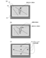
自動焦点検出回路203は、撮像素子2におけるCCDの中に含まれる、位相差検出のために使用される複数の検出素子(複数の画素)からの信号電圧をA/D変換し、CPU3に送る。CPU3は、複数の検出素子の信号から、各焦点検出ポイントに対応する被写体までの距離を演算する。これは撮像面位相差AFとして知られる公知の技術である。本実施形態では、一例として、図3(a)のファインダ内視野像(視認用画像)に示した180か所に対応する撮像面上の180か所のそれぞれに、焦点検出ポイントがあるとする。
The automatic focus detection circuit 203 A/D converts signal voltages from a plurality of detection elements (a plurality of pixels) included in the CCD of the
追尾処理回路207は、撮像素子2によって撮像された画像に基づいて物体の追尾処理を行う。具体的には、追尾処理回路207は、現フレーム画像(現在のフレーム画像)と、基準画像とのマッチング処理を行い、基準画像と最も類似度(相関度)が高い領域を追尾対象物の領域として現フレーム画像から抽出(検出)する。本実施形態では、基準画像は、前フレーム画像(現在よりも前のフレーム画像)のうち、追尾対象物の領域として検出した領域の画像(部分画像)である。また、上記類似度は、画像の特徴量の類似度であってもよい。そして、追尾処理回路207は、類似度に応じて追尾を継続するか否かを判断する。また、追尾処理回路207は、追尾信頼度(追尾処理の信頼度;追尾の状態値)を、検出した領域に対応する類似度に基づいて算出し、CPU3に送る。追尾処理は、オートフォーカス制御等のために行われ、追尾信頼度は、被写体を示すGUIの表示制御等に用いられる。
The tracking processing circuit 207 performs object tracking processing based on the image captured by the
図3(a)は、ファインダ内視野を示した図であり、表示デバイス10が動作した状態(視認用画像を表示した状態)を示す。図3(a)に示すように、ファインダ内視野には、焦点検出領域300、180個の測距点指標301、視野マスク302等がある。180個の測距点指標301のそれぞれは、撮像面上における焦点検出ポイントに対応する位置に表示されるように、表示デバイス10に表示されたスルー画像(ライブビュー画像)に重ねて表示される。また、180個の測距点指標301のうち、現在の視点A(推定位置)に対応する測距点指標301は、枠等で強調されて表示される。
FIG. 3A is a diagram showing the field of view in the finder, and shows a state in which the
<視線検出動作の説明>
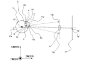
図4,図5(a),図5(b),図6を用いて、視線検出方法について説明する。図4は、視線検出方法の原理を説明するための図であり、視線検出を行うための光学系の概略図である。図4に示すように、光源13a,13bは受光レンズ16の光軸に対して略対称に配置され、ユーザーの眼球14を照らす。光源13a,13bから発せられて眼球1
4で反射した光の一部は、受光レンズ16によって、眼用撮像素子17に集光する。図5(a)は、眼用撮像素子17で撮像された眼画像(眼用撮像素子17に投影された眼球像)の概略図であり、図5(b)は眼用撮像素子17におけるCCDの出力強度を示す図である。図6は、視線検出動作の概略フローチャートを表す。
<Explanation of gaze detection operation>
The line of sight detection method will be explained using FIGS. 4, 5(a), 5(b), and 6. FIG. 4 is a diagram for explaining the principle of the line-of-sight detection method, and is a schematic diagram of an optical system for detecting the line-of-sight. As shown in FIG. 4, the
A part of the light reflected by the
視線検出動作が開始すると、図6のステップS601で、光源13a,13bは、ユーザーの眼球14に向けて赤外光を発する。赤外光によって照明されたユーザーの眼球像は、受光レンズ16を通して眼用撮像素子17上に結像され、眼用撮像素子17により光電変換される。これにより、処理可能な眼画像の電気信号が得られる。
When the line of sight detection operation starts, in step S601 in FIG. 6, the
ステップS602では、視線検出回路201は、眼用撮像素子17から得られた眼画像(眼画像信号;眼画像の電気信号)をCPU3に送る。
In step S602, the line of
ステップS603では、CPU3は、ステップS602で得られた眼画像から、光源13a,13bの角膜反射像Pd,Peと瞳孔中心cに対応する点の座標を求める。
In step S603, the
光源13a,13bより発せられた赤外光は、ユーザーの眼球14の角膜142を照明する。このとき、角膜142の表面で反射した赤外光の一部により形成される角膜反射像Pd,Peは、受光レンズ16により集光され、眼用撮像素子17上に結像して、眼画像における角膜反射像Pd’,Pe’となる。同様に瞳孔141の端部a,bからの光束も眼用撮像素子17上に結像して、眼画像における瞳孔端像a’,b’となる。
The infrared light emitted from the
図5(b)は、図5(a)の眼画像における領域α’の輝度情報(輝度分布)を示す。図5(b)では、眼画像の水平方向をX軸方向、垂直方向をY軸方向とし、X軸方向の輝度分布が示されている。本実施形態では、角膜反射像Pd’,Pe’のX軸方向(水平方向)の座標をXd,Xeとし、瞳孔端像a’,b’のX軸方向の座標をXa,Xbとする。図5(b)に示すように、角膜反射像Pd’,Pe’の座標Xd,Xeでは、極端に高いレベルの輝度が得られる。瞳孔141の領域(瞳孔141からの光束が眼用撮像素子17上に結像して得られる瞳孔像の領域)に相当する、座標Xaから座標Xbまでの領域では、座標Xd,Xeを除いて、極端に低いレベルの輝度が得られる。そして、瞳孔141の外側の光彩143の領域(光彩143からの光束が結像して得られる、瞳孔像の外側の光彩像の領域)では、上記2種の輝度の中間の輝度が得られる。具体的には、X座標(X軸方向の座標)が座標Xaより小さい領域と、X座標が座標Xbより大きい領域とで、上記2種の輝度の中間の輝度が得られる。
FIG. 5(b) shows brightness information (brightness distribution) of area α' in the eye image of FIG. 5(a). In FIG. 5B, the horizontal direction of the eye image is the X-axis direction, the vertical direction is the Y-axis direction, and the luminance distribution in the X-axis direction is shown. In this embodiment, the coordinates of the corneal reflection images Pd' and Pe' in the X-axis direction (horizontal direction) are Xd and Xe, and the coordinates of the pupil edge images a' and b' in the X-axis direction are Xa and Xb. As shown in FIG. 5B, an extremely high level of brightness is obtained at the coordinates Xd and Xe of the corneal reflection images Pd' and Pe'. In the area from the coordinate Xa to the coordinate Xb, which corresponds to the area of the pupil 141 (the area of the pupil image obtained when the light flux from the
図5(b)に示すような輝度分布から、角膜反射像Pd’,Pe’のX座標Xd,Xeと、瞳孔端像a’,b’のX座標Xa,Xbを得ることができる。具体的には、輝度が極端に高い座標を角膜反射像Pd’,Pe’の座標として得ることができ、輝度が極端に低い座標を瞳孔端像a’,b’の座標として得ることができる。また、受光レンズ16の光軸に対する眼球14の光軸の回転角θxが小さい場合には、瞳孔中心cからの光束が眼用撮像素子17上に結像して得られる瞳孔中心像c’(瞳孔像の中心)の座標Xcは、Xc≒(Xa+Xb)/2と表すことができる。つまり、瞳孔端像a’,b’のX座標Xa,Xbから、瞳孔中心像c’の座標Xcを算出できる。このようにして、角膜反射像Pd’,Pe’の座標と、瞳孔中心像c’の座標とを見積もることができる。
From the brightness distribution as shown in FIG. 5(b), the X coordinates Xd, Xe of the corneal reflection images Pd', Pe' and the X coordinates Xa, Xb of the pupil edge images a', b' can be obtained. Specifically, coordinates with extremely high brightness can be obtained as the coordinates of the corneal reflection images Pd', Pe', and coordinates with extremely low brightness can be obtained as the coordinates of the pupil edge images a', b'. . Furthermore, when the rotation angle θx of the optical axis of the
ステップS604では、CPU3は、眼球像の結像倍率βを算出する。結像倍率βは、受光レンズ16に対する眼球14の位置により決まる倍率で、角膜反射像Pd’,Pe’の間隔(Xd-Xe)の関数を用いて求めることができる。
In step S604, the
ステップS605では、CPU3は、受光レンズ16の光軸に対する眼球14の光軸の
回転角を算出する。角膜反射像Pdと角膜反射像Peの中点のX座標と角膜142の曲率中心OのX座標とはほぼ一致する。このため、角膜142の曲率中心Oから瞳孔141の中心cまでの標準的な距離をOcとすると、Z-X平面(Y軸に垂直な平面)内での眼球14の回転角θXは、以下の式1で算出できる。Z-Y平面(X軸に垂直な平面)内での眼球14の回転角θyも、回転角θxの算出方法と同様の方法で算出できる。
β×Oc×SINθX≒{(Xd+Xe)/2}-Xc ・・・(式1)
In step S605, the
β×Oc×SINθ X ≒ {(Xd+Xe)/2}−Xc (Formula 1)
ステップS606では、CPU3は、ステップS605で算出した回転角θx,θyを用いて、表示デバイス10に表示された視認用画像におけるユーザーの視点(視線が注がれた位置;ユーザーが見ている位置)を求める(推定する)。視点の座標(Hx,Hy)が瞳孔中心cに対応する座標であるとすると、視点の座標(Hx,Hy)は以下の式2,3で算出できる。
Hx=m×(Ax×θx+Bx) ・・・(式2)
Hy=m×(Ay×θy+By) ・・・(式3)
In step S606, the
Hx=m×(Ax×θx+Bx) (Formula 2)
Hy=m×(Ay×θy+By) (Formula 3)
式2,3のパラメータmは、カメラ1のファインダ光学系(受光レンズ16等)の構成で定まる定数であり、回転角θx,θyを視認用画像において瞳孔中心cに対応する座標に変換する変換係数であり、予め決定されてメモリ部4に格納されるとする。パラメータAx,Bx,Ay,Byは、視線の個人差を補正する視線補正パラメータであり、後述するキャリブレーション作業を行うことで取得され、視線検出動作が開始する前にメモリ部4に格納されるとする。
The parameters m in
ステップS607では、CPU3は、視点の座標(Hx,Hy)をメモリ部4に格納し、視線検出動作を終える。
In step S607, the
上述の説明では、光源13a,13bの角膜反射像を利用して表示デバイス上での視点(注視点)の座標を取得する方法について説明したが、これに限らず、撮像された眼球画像から視点の座標(眼球回転角度)を取得する手法であれば適用することができる。
In the above explanation, the method of obtaining the coordinates of the viewpoint (point of gaze) on the display device using the corneal reflection images of the
<キャリブレーション作業の説明>
前述のように、視線検出動作において眼画像から眼球14の回転角度θx,θyを取得し、瞳孔中心cの位置を視認用画像上での位置に座標変換することで、視点を推定できる。
<Explanation of calibration work>
As described above, the viewpoint can be estimated by acquiring the rotation angles θx and θy of the
しかし、人間の眼球の形状の個人差等の要因により、視点を高精度に推定できないことがある。具体的には、視線補正パラメータAx,Ay,Bx,Byをユーザーに適した値に調整しなければ、図3(b)に示したように、実際の視点Bと推定された視点Cとのずれが生じてしまう。図3(b)では、ユーザーは人物を注視しているが、カメラ1は背景が注視されていると誤って推定しており、適切な焦点検出及び調整ができない状態に陥ってしまっている。
However, due to factors such as individual differences in the shape of human eyeballs, it may not be possible to estimate the viewpoint with high accuracy. Specifically, unless the line-of-sight correction parameters Ax, Ay, Bx, and By are adjusted to values suitable for the user, the difference between the actual viewpoint B and the estimated viewpoint C will change, as shown in Figure 3(b). A misalignment will occur. In FIG. 3(b), the user is gazing at a person, but the
そこで、カメラ1が撮像を行う前に、キャリブレーション作業を行い、ユーザーに適した視点補正パラメータを取得し、カメラ1に格納する必要がある。
Therefore, before the
従来より、キャリブレーション作業は、撮像前に図3(c)のような位置の異なる複数の指標を視認用画像で強調表示し、ユーザーにその指標を見てもらうことで行われている
。そして、各指標の注視時に視線検出動作を行い、算出された複数の視点(推定位置)と、各指標の座標とから、ユーザーに適した視点補正パラメータを求める技術が、公知の技術として知られている。なお、ユーザーの見るべき位置が示唆されれば、指標の表示でなくてもよく、輝度や色の変更で位置が強調されてもよい。
Conventionally, calibration work has been performed by highlighting a plurality of indicators at different positions in a visual image as shown in FIG. 3C before imaging, and having the user look at the indicators. Then, there is a well-known technology that performs a line-of-sight detection operation when gazing at each index, and calculates viewpoint correction parameters suitable for the user from the calculated multiple viewpoints (estimated positions) and the coordinates of each index. ing. Note that as long as the position to be viewed by the user is suggested, the position need not be displayed as an index, and the position may be emphasized by changing the brightness or color.
<従来の追尾処理(従来手法)>
図7(a)~図7(d)は、従来手法におけるフレーム画像701の表示例を示す図である。フレーム画像701内には、被写体702と被写体を追尾した領域を示す被写体GUI703とが表示されている。被写体GUI703は、カメラが動きのある被写体として識別している領域(被写体認識領域;認識領域)を示すGUI画像である。ユーザーは画面をタッチするなどして被写体702が追尾対象の被写体であることをカメラに指示し、被写体を画面に収めながら動画を撮影する。
<Conventional tracking processing (conventional method)>
FIGS. 7(a) to 7(d) are diagrams showing display examples of a
図7(a)は、追尾対象の物体(被写体)を追尾し始めた直後であって、被写体702と被写体GUI703とが一致している状態を示す図である。この時、被写体702と被写体GUI703で囲まれる領域との類似度(被写体認識領域の確からしさ)を表す追尾信頼度(例えば、0~100%)は高い値となる。なお、追尾信頼度は、被写体GUI703の位置の信頼度と捉えることもできる。図7(b),図7(c)は、被写体702が高速で移動したり、または背景物体と同化したりすることで、被写体GUI703が被写体702から徐々にずれていく様子を示す図である。図7(d)は、追尾信頼度が閾値Thを下回り、追尾処理を停止して被写体GUI703が非表示となった状態を示す図である。
FIG. 7A is a diagram showing a state where the
上述のように、従来の追尾処理では、被写体702が高速で移動したり、背景物体と同化する場合に、被写体を適切に追尾できないことがある。ここで、被写体702の追尾処理において、ユーザーの視線704に基づいて被写体認識領域を調整することが考えられる。図7(d)に示すように、被写体GUI703が非表示となった後であれば、視線704が被写体702をとらえやすいため、視線704に基づいて被写体認識領域を調整することは有用である。しかし、図7(c)に示すように、被写体702からずれた被写体GUI703が表示されていると、視線704は被写体GUI703を向きやすく、被写体702に保ちにくい。そのため、図7(c)に示すフレーム画像の状態において、視線704に基づいて被写体認識領域を調整すると、被写体認識領域と実際の被写体とのずれが生じてしまう。
As described above, in conventional tracking processing, when the subject 702 moves at high speed or blends into a background object, the subject may not be properly tracked. Here, in the tracking process of the subject 702, it is conceivable to adjust the subject recognition area based on the user's line of
<視点を用いた追尾処理(本実施形態)>
図8は、本実施形態に係る追尾処理の例を示すフローチャートである。このフローチャートにおける各処理は、CPU3が、メモリ部4に格納されているプログラムを実行することで実現される。また、本実施形態では、このフローチャートにおける処理は、カメラの電源がONにされると開始される。
<Tracking processing using viewpoint (this embodiment)>
FIG. 8 is a flowchart illustrating an example of tracking processing according to this embodiment. Each process in this flowchart is realized by the
ステップS801では、カメラの電源がONにされて撮像素子2によってスルー画像(入力画像)の取得が開始されると、CPU3は、表示デバイス10でのスルー画像の表示を開始する。本実施形態では、ユーザーは、ファインダ内の表示デバイス10に表示されたスルー画像を見ることで被写体の視認を行う。
In step S<b>801 , when the power of the camera is turned on and acquisition of a through image (input image) by the
ステップS802では、CPU3は、視線入力がONであるか否かを判定する。本実施形態では、CPU3は、視線検出機能(視線入力機能)がONになっている場合に視線入力がONであると判定するものとする。視線入力がONの場合はステップS803に進み、そうでない場合はステップS808に進む。
In step S802, the
ステップS803では、CPU3は、図6に示す視線検出ルーチンを実行する。本実施形態では、図6で示した視線検出ルーチンを実行することで、表示デバイス10上での上述の視点の座標(Hx,Hy)を取得する。
In step S803, the
ステップS804では、CPU3は、被写体の位置を示す被写体GUIと視点(視線の位置;推定注視点)を示す視線GUIとが重なりあっているか否かを判定する。重なりあっている場合はステップS806に進み、そうでない場合はステップS805に進む。ここで、被写体GUIと視線GUIとが重なりあっている場合として、例えば、被写体GUIである線と視線GUIである線とが交差している場合や、被写体GUIの領域と視線GUIの領域との一方に他方の少なくとも一部が含まれる場合等が挙げられる。なお、被写体GUIは後述するステップS813で表示されるため、被写体GUIが表示されていない場合(処理開始直後など)は、ステップS805に進むものとする。
In step S804, the
ステップS805では、CPU3は、視線GUIを表示デバイス10に表示する。本実施形態では、視線GUIは、ユーザーの視線の位置を囲む枠である。
In step S805, the
ステップS806では、CPU3は、視線GUIを非表示にする。これは、被写体に被写体GUIと視線GUIが重複して表示されると、当該被写体が見づらくなり、ユーザーに不快感を与えるおそれがあるためである。なお、被写体GUIを見やすくすることができればよく、視線GUIの色を薄くしたり、視線GUIを小さくしたりして、視線GUIを目立たなくしてもよい。
In step S806, the
ステップS807では、CPU3は、閾値Thを閾値Th1に設定する。ステップS808では、CPU3は、閾値Thを閾値Th2(<閾値Th1)に設定する。詳細は後述するが、本実施形態では、追尾信頼度が閾値Th以下になると被写体GUIを消す(非表示にする)ことで、被写体からずれた被写体GUIに視線が向くことを防ぐ。そのため、視点を検出する場合の閾値Th1は、視点を検出しない場合の閾値Th2に比べて大きくしている。これにより、視点を検出する場合に、被写体GUIのずれ始めを素早く検知し、視線を被写体に向けやすくすることが可能となる。本実施形態では、閾値Th1を70%、閾値Th2を50%とする例について説明する。
In step S807, the
ステップS809では、CPU3は、追尾処理回路207を制御して、動体検出(追尾処理)を行う。CPU3は、視点に基づかずに物体の位置を抽出していると捉えることもできる。動体検出方法は、既存の種々の方法を適用可能である。例えば、前述したように、フレーム間のマッチング処理を行い、フレーム間の類似度(相関度)が最も高い領域を被写体認識領域として検出する。また、CPU3は、追尾処理回路207を制御して、検出した領域に対応する類似度に応じて追尾信頼度を算出する。なお、追尾信頼度は、類似度が高いほど高くなる。
In step S809, the
ステップS810では、CPU3は、ステップS809の結果(動体の領域の検出結果)を被写体位置情報として設定する。被写体位置情報は、例えば、測距点として用いられる。
In step S810, the
ステップS811では、CPU3は、追尾信頼度が閾値Thより低いか否かを判定する。追尾信頼度が閾値Thより低い場合はステップS812に進み、そうでない場合は、ステップS813に進む。ここで、追尾信頼度が閾値Thより低い場合とは、被写体位置と被写体GUIの位置にずれが生じている場合である。また、追尾信頼度が閾値Thより高い場合とは、被写体位置と被写体GUIの位置が略一致している場合である。
In step S811, the
ステップS812では、CPU3は、被写体GUIを非表示にする。なお、被写体GU
Iに視線が向くのを防ぐことができればよく、被写体GUIの色を薄くすることや、被写体GUIを小さくする等を行って被写体GUIを目立たなくしてもよい。また、被写体GUIの他にも、撮影画面上には撮影設定情報を表示するOSD(On Screen Display)がGUIとして表示されていることがある。これらのOSDも、視線が被写体以外に向いてしまい、視線情報を用いた追尾処理を妨げる要因となりうるので、被写体GUIと同様にOSDの表示態様を変更する(OSDを目立たなくする)とよい。なお、被写体GUIを非表示にして視線GUIのみが表示されることで、視線入力によって追尾処理を行っていることをユーザーが認識しやすくすることもできる。
In step S812, the
It is only necessary to prevent the line of sight from turning to I, and the subject GUI may be made less conspicuous by making the subject GUI lighter in color or smaller. In addition to the subject GUI, an OSD (On Screen Display) that displays shooting setting information may be displayed as a GUI on the shooting screen. These OSDs can also direct the line of sight to something other than the subject, which can be a factor that impedes tracking processing using line-of-sight information, so it is better to change the display mode of the OSD (make the OSD less noticeable) in the same way as the subject GUI. Note that by hiding the subject GUI and displaying only the line-of-sight GUI, it is possible to make it easier for the user to recognize that tracking processing is being performed through line-of-sight input.
ステップS813では、CPU3は、被写体GUIを表示する。これは、被写体位置と被写体GUIの位置とが略一致している可能性が高いためである。
In step S813, the
ステップS814では、CPU3は、視線情報に基づいて被写体位置情報を更新する。ここで、上述のステップS812において被写体GUIを非表示にしているため、ユーザーは被写体を注視している可能性が高い。よって、視線の位置と被写体認識領域の位置とを重みづけ加算して被写体認識領域を補正することで、被写体認識領域と被写体とのずれを低減している。なお、視線の位置を含む領域(視線GUIに対応する領域)をそのまま被写体認識領域として用いてもよい。なお、信頼度が閾値Thより低い場合に、CPU3は、ステップS809で視点に基づかずに抽出された物体の位置を視点に基づいて補正した物体の位置を、被写体認識領域(視点に基づいて検出された位置)として検出していると捉えることもできる。また、信頼度が閾値Thより高い場合に、CPU3は、(視線に基づいて補正せずに)抽出された物体の位置を、被写体認識領域(視線に基づかずに検出された位置)として検出していると捉えることもできる。
In step S814, the
ステップS815では、CPU3は、ユーザーの操作によっての撮影スイッチ(不図示)がONにされたか否かを判定する。ONにされた場合はステップS816に進み、そうでない場合はステップS802に戻る。
In step S815, the
ステップS816では、CPU3は、撮影動作を行う。具体的には、CPU3は、撮像素子2によって取得された画像信号をメモリ部4に記録する。
In step S816, the
ステップS817では、CPU3は、撮影が終了したか否かを判定する。撮影が終了した場合は本処理フローを終了し、そうでない場合はステップS802に戻る。撮影が終了した場合とは、例えば、電源がOFFにされた場合である。
In step S817, the
図9(a)~図9(d)は、それぞれ本実施形態における動画やライブビューにおけるフレーム画像701の一例を示す。
FIGS. 9(a) to 9(d) each show an example of a
図9(a)は、動体である被写体702を追尾し始めた直後であって、被写体702と被写体GUI703が一致している状態を示す図である。この時、追尾信頼度は高い値(例えば、90%)となる。また、図9(a)には、OSD901、視線GUI905が表示されている。ここで、視線検出機能がオンであるため、閾値Thは閾値Th1(例えば、70%)である。
FIG. 9A is a diagram showing a state where the
図9(b)は、被写体702の位置と被写体GUI703とがずれ始めているが、追尾信頼度(例えば、80%)が閾値Th(閾値Th1)より高い状態を示す図である。また、図9(b)は、被写体GUI703と視線GUI905とが重なりあっている状態を示している。視線GUI905と被写体GUI703とが重なりあうと情報が煩雑になり、ユーザーに不快感を与えるおそれがある。そのため、本実施形態では、被写体GUI703と視線GUI905とが重なりあう場合には、被写体GUI703の見やすさを優先す
る(図9(b)の例では視線GUI905を非表示にしている)。
FIG. 9B is a diagram showing a state in which the position of the subject 702 and the
図9(c)は、被写体702の位置と被写体GUI703とが大きくずれており、追尾信頼度(例えば、60%)が閾値Th(閾値Th1)を下回った状態を示す図である。図9(c)の例では、被写体GUI703を非表示にして目立たなくしている。また、図9(c)の例では、OSD901の色を薄くして目立たなくしている。本実施形態では、視線検出機能がONの場合に、比較的大きい閾値Th1を用いることで、被写体GUI703のずれ始めを素早くに検知している。そして、被写体GUI703のずれ始めを検知した場合に、被写体GUI703を非表示にしたりOSD901の色を薄くすることでユーザーの視線を被写体GUI703やOSD901に向けにくくして、ユーザーの視線を被写体702に向けやすくしている。
FIG. 9C is a diagram showing a state in which the position of the subject 702 and the
図9(d)は、視線の位置に基づいて追尾処理を行った結果、被写体GUI703の位置と被写体702の位置とが再び略一致した状態を示す図である。図9(d)の例では、追尾信頼度(例えば、90%)が閾値Th(閾値Th1)より高くなったため、被写体GUI703を再び表示して、OSD901を通常の色に戻している。なお、図9(d)の例では、視線GUI905は、被写体GUI703に重なるので非表示となっている。
FIG. 9D is a diagram showing a state in which the position of the
以上のように、本実施形態では、視線検出機能がONの場合に、追尾信頼度を評価するための閾値Thを大きくする。このようにして、被写体GUIと被写体の位置とのずれ始めを素早く検知し、被写体GUI703を目立たなくすることで、ユーザーの視線を被写体に向けやすくして、視線情報を用いた追尾処理の精度を向上させることができる。また、被写体GUIを目立たなくすることによって、ユーザーに視線情報を用いて追尾処理を行っていることを意識させることで、ユーザーが被写体を注視しやすくしている。
As described above, in this embodiment, when the line of sight detection function is ON, the threshold Th for evaluating the tracking reliability is increased. In this way, the beginning of a shift between the subject GUI and the subject position is quickly detected, and the
(実施形態2)
実施形態1では、被写体GUIの位置と視線位置が重なりあう場合を除いて、視線GUIを常時表示させる例について説明したが、本実施形態では、視線情報を用いて追尾処理を行う場合のみ視線GUIを表示する例について説明する。
(Embodiment 2)
In the first embodiment, an example was explained in which the line-of-sight GUI is always displayed except when the position of the subject GUI and the line-of-sight position overlap, but in this embodiment, the line-of-sight GUI is displayed only when tracking processing is performed using line-of-sight information. An example of displaying will be explained.
図10は、本実施形態に係る追尾処理の例を示すフローチャートである。このフローチャートにおける各処理は、CPU3が、メモリ部4に格納されているプログラムを実行することで実現される。また、本実施形態では、このフローチャートにおける処理は、カメラの電源がONにされると開始される。なお、図8に示す処理と同じ処理については、同じ番号を付して説明を省略する。
FIG. 10 is a flowchart illustrating an example of tracking processing according to this embodiment. Each process in this flowchart is realized by the
本実施形態では、図8に示すステップS804~S806の処理は行わないため、視線検出ルーチンを行った直後に視線GUIを表示したり非表示にしたりする処理は行われない。視線GUIが表示されるタイミングは、ステップS811で追尾信頼度が閾値Thを下回り、被写体GUI703が非表示にされた後のタイミング(ステップS1018)である。また、視線GUIが非表示にされるタイミングは、ステップS811で追尾信頼度が閾値Thを上回り、被写体GUI703が表示された後のタイミング(ステップS1019)である。
In this embodiment, the processes of steps S804 to S806 shown in FIG. 8 are not performed, so the process of displaying or hiding the visual line GUI immediately after performing the visual line detection routine is not performed. The timing at which the line-of-sight GUI is displayed is the timing after the tracking reliability falls below the threshold Th in step S811 and the
このようにすることで、視線GUIを必要以上に表示してユーザーに不快感を与えることなく、視線情報を用いて追尾処理を行っていることをユーザーに認識させることが可能となる。 By doing so, it is possible to make the user aware that the tracking process is being performed using the line-of-sight information without causing discomfort to the user by displaying the line-of-sight GUI more than necessary.
図11(a)~図11(d)は、それぞれ本実施形態における動画やライブビューにおけるフレーム画像701を示している。
FIGS. 11(a) to 11(d) each show a
図11(a)は、動体である被写体702を追尾し始めた直後であって、被写体702と被写体GUI703が一致している(追尾信頼度が閾値Th1より高い)状態を示す図である。このとき、視線GUI905と被写体GUI703が同時に表示デバイス10上に表示されると、表示デバイス10上の情報が煩雑になり、ユーザーに不快感を与えるおそれがあるため、実施形態1とは異なり、視線GUI905は表示されていない。
FIG. 11A is a diagram showing a state where the
図11(c)は、追尾信頼度が閾値Thを下回った(ステップS811-Yes)状態を示す図である。この場合、視線情報を用いて追尾処理が行われることをユーザーに認識させるために、視線GUI905が表示される。一方、図11(b),図11(d)では、追尾信頼度が閾値Thより高い(ステップS811-No)ため、図11(a)と同様に視線GUI905を非表示にしている。
FIG. 11(c) is a diagram showing a state in which the tracking reliability is lower than the threshold Th (step S811-Yes). In this case, the line-of-
以上のように、本実施形態では、視線情報が追尾処理に使用される場合のみ視線GUIを表示する。このようにすることで、表示デバイス10上の情報の煩雑さを抑えつつ、ユーザーの視線を被写体に向けやすくして、視線情報を用いた追尾処理の精度を向上させることができる。また、視線情報を用いて追尾処理を行っていることをユーザーに認識させることができる。
As described above, in this embodiment, the visual line GUI is displayed only when visual line information is used for tracking processing. By doing so, it is possible to suppress the complexity of the information on the
(実施形態3)
上述の実施形態では、動体の追尾処理を行う際に視線情報を用いる例について説明したが、本実施形態では、顔検出を行う際に視線情報を用いる例について説明する。
(Embodiment 3)
In the above-described embodiment, an example in which line-of-sight information is used when tracking a moving object is performed, but in this embodiment, an example in which line-of-sight information is used when performing face detection will be described.
図12は、本実施形態におけるカメラ1内の電気的構成を示すブロック図である。図12では、図2における追尾処理回路207の代わりに顔検出回路208が設けられている。
FIG. 12 is a block diagram showing the electrical configuration inside the
顔検出回路208は、あらかじめメモリ部4に記憶される人の顔のテンプレートデータを用いて、フレーム画像内で当該テンプレートとの類似度が基準値以上となる部分(領域)を顔画像として検出する。なお、顔検出の方法は上記に限定されず、公知の種々の技術を適用可能である。
The
図13は、本実施形態に係る顔検出処理を示すフローチャートである。このフローチャートにおける各処理は、CPU3が、メモリ部4に格納されているプログラムを実行することで実現される。また、本実施形態では、このフローチャートにおける処理は、カメラの電源がONにされると開始される。なお、図8に示す処理と同じ処理については、同じ番号を付して説明を省略する。
FIG. 13 is a flowchart showing face detection processing according to this embodiment. Each process in this flowchart is realized by the
ステップS1304では、CPU3は、顔の位置を示す顔GUIと視線GUIとが重なりあっているか否かを判定する。重なりあっている場合はステップS806に進み、そうでない場合はステップS805に進む。ここで、顔GUIと視線GUIとが重なりあっている場合として、例えば、顔GUIである線と視線GUIである線とが交差している場合や、顔GUIの領域と視線GUIの領域との一方に他方の少なくとも一部が含まれる場合等が挙げられる。なお、顔GUIは後述するステップS1313で表示されるため、顔GUIが表示されていない場合(処理開始直後など)は、ステップS805に進むものとする。
In step S1304, the
ステップS1307では、CPU3は、閾値Thを閾値Th1に設定する。ステップS1308では、CPU3は、閾値Thを閾値Th2(<閾値Th1)に設定する。本実施形態では、後述処理によって後述の顔信頼度が閾値Th以下になると顔GUIを消す(非
表示にする)ことで、顔からずれた顔GUIに視線が向くことを防ぐ。そのため、視点を検出する場合の閾値Th(閾値Th1)は、視点を検出しない場合の閾値Th(閾値Th2)に比べて大きくしている。これにより、視点を検出する場合に、顔GUIのずれ始めを検知し、視線を顔に向けやすくすることが可能となる。本実施形態では、閾値Th1を70%、閾値Th2を50%とする例について説明する。
In step S1307, the
ステップS1309では、CPU3は、顔検出回路208を制御して、顔検出を行う。顔検出方法は、既存の種々の方法を適用可能である。例えば、現在のフレームにおける画像において、基準画像とのマッチング処理を行い、基準画像と最も類似度(相関度)が高い領域を抽出する。基準画像は、例えば、あらかじめメモリ部4に格納されている顔のテンプレート画像である。また、CPU3は、顔検出回路208を制御して、検出した領域に対応する類似度に応じて顔信頼度を算出する。なお、顔信頼度は、類似度が高いほど高くなる。
In step S1309, the
ステップS1310では、CPU3は、ステップS1309の結果(顔の領域の検出結果)を顔位置情報として設定する。顔位置情報は、例えば、測距点として用いられる。
In step S1310, the
ステップS1311では、CPU3は、顔信頼度が閾値Thより低いか否かを判定する。顔信頼度が閾値Thより低い場合はステップS812に進み、そうでない場合は、ステップS813に進む。ここで、顔信頼度が閾値Thより低い場合とは、顔位置と顔GUIの位置にずれが生じている場合である。また、顔信頼度が閾値Thより高い場合とは、顔位置と顔GUIの位置とが略一致している場合である。
In step S1311, the
ステップS1312では、CPU3は、顔GUIを非表示にする。これは、顔位置と顔GUIの位置のずれが大きい可能性が高いためである。なお、顔GUIに視線が向くのを防ぐことができればよく、顔GUIの色を薄くしたり、顔GUIを小さくしたりして、顔GUIを目立たなくしてもよい。また、実施形態1と同様にOSDの表示態様を変更する(目立たなくする)とよい。なお、顔GUIを非表示にして視線GUIのみが表示されることで、視線入力によって顔検出処理を行っていることをユーザーが認識しやすくすることもできる。
In step S1312, the
ステップS1313では、CPU3は、顔GUIを表示する。これは、顔位置と顔GUIの位置とが略一致している可能性が高いためである。
In step S1313, the
ステップS1314では、CPU3は、視線情報に基づいて顔位置情報を更新する。例えば、視線の位置と顔と認識された領域(顔認識領域)の位置とを重みづけ加算して顔認識領域を補正することで、顔認識領域と顔とのずれを低減することができる。なお、視線の位置を含む領域(視線GUIに対応する領域)をそのまま顔認識領域として用いてもよい。
In step S1314, the
以上説明したように本実施形態によれば、視線検出機能を使用する場合に、顔信頼度の閾値を大きくすることで、顔GUIと顔位置のずれはじめを素早く検知し、顔GUIを非表示とする。これにより、視線が顔に向きやすくなるため、視線情報を用いた顔検出処理の精度を向上させることが可能となる。 As explained above, according to this embodiment, when using the line of sight detection function, by increasing the face reliability threshold, the beginning of a shift between the face GUI and the face position is quickly detected, and the face GUI is hidden. shall be. This makes it easier to direct the line of sight toward the face, making it possible to improve the accuracy of face detection processing using line-of-sight information.
(変形例)
上述の実施形態では、GUIを目立たなくする方法として、非表示にしたりサイズを小さくしたり、色を薄くする例について説明したが、これらに限定されない。例えば、輝度や色を背景に応じて(背景の輝度や色に近づけるように)変更したり、GUIの透過度(透明度)を高くする等によってGUIを目立たなくしてもよい。
(Modified example)
In the above-described embodiment, an example of hiding the GUI, reducing the size, or making the color lighter has been described as a method for making the GUI less noticeable, but the method is not limited to these. For example, the GUI may be made inconspicuous by changing the brightness or color depending on the background (so that it approaches the brightness or color of the background) or by increasing the transparency of the GUI.
上述の実施形態では、被写体GUIと視線の位置を示す視線GUIとが重なりあっている場合に、被写体GUIを目立つように、視線GUIを目立たなくする例について説明したが、視線GUIを目立つように、被写体GUIを目立たなくしてもよい。具体的には、被写体GUIと視線の位置を示す視線GUIとが重なりあっている場合に、被写体GUIの輝度や色、サイズ等を変更することで被写体GUIを目立たなくするとよい。 In the above-described embodiment, an example was described in which when the subject GUI and the line-of-sight GUI indicating the line-of-sight position overlap, the subject GUI is made conspicuous and the line-of-sight GUI is made inconspicuous. , the subject GUI may be made inconspicuous. Specifically, when the subject GUI and the line-of-sight GUI indicating the line-of-sight position overlap, the subject GUI may be made less noticeable by changing the brightness, color, size, etc. of the subject GUI.
上述の実施形態では、カメラにおいて被写体の追尾処理や顔検出処理を行う場合に、被写体GUIや顔GUIを目立たなくすることで、ユーザーの視線を所望の領域(被写体や顔を含む領域)に向けやすくする例について説明した。しかし、追尾処理や顔検出処理を行っていない場合にも本発明を適用可能である。例えば、表示装置においてユーザーの視点(視線の位置)の検出が行われている場合に、所望の領域と異なる領域にGUI画像が表示されていると、ユーザーの視線は当該GUI画像を向きやすい。そのため、ユーザーの視線を所望の領域に向けやすくするために、ユーザーの視点(視線の位置)の検出を行っている場合に、当該視点の検出を行っていない場合に比べてGUI画像を目立たなくしてもよい。例えば、本発明は、以下の表示制御部と検出部とを備える電子機器として捉えることもできる。ここで、表示制御部は、入力画像とGUI画像とを表示部に表示する。検出部は、入力画像におけるユーザーの視点を検出する。また、検出部は、検出部が視点の検出を行っている場合に、表示制御部が、視点の検出を行っていない場合に比べて、GUI画像を目立たなくする。 In the embodiment described above, when performing subject tracking processing or face detection processing in the camera, the user's line of sight is directed to the desired area (the area containing the subject or face) by making the subject GUI and face GUI inconspicuous. I explained an example of how to make it easier. However, the present invention can be applied even when tracking processing or face detection processing is not performed. For example, when a user's viewpoint (position of line of sight) is detected on a display device, if a GUI image is displayed in an area different from a desired area, the user's line of sight tends to be directed toward the GUI image. Therefore, in order to make it easier to direct the user's line of sight to a desired area, when the user's viewpoint (position of the line of sight) is detected, the GUI image is made less conspicuous than when the user's viewpoint is not detected. It's okay. For example, the present invention can also be understood as an electronic device including the following display control section and detection section. Here, the display control section displays the input image and the GUI image on the display section. The detection unit detects the user's viewpoint in the input image. Furthermore, when the detection unit is detecting a viewpoint, the display control unit makes the GUI image less noticeable than when the display control unit is not detecting a viewpoint.
また、上述の実施形態では、本発明をカメラに適用した例について説明したが、これに限定されない。例えば、本発明は、視線入力を受け付け可能な電子機器であれば適用可能である。例えば、本発明はパーソナルコンピュータやPDA、携帯電話端末、ディスプレイ、HMD(ヘッドマウントディスプレイ)等にも適用可能である。 Further, in the above-described embodiment, an example in which the present invention is applied to a camera has been described, but the present invention is not limited thereto. For example, the present invention is applicable to any electronic device that can accept line-of-sight input. For example, the present invention is applicable to personal computers, PDAs, mobile phone terminals, displays, HMDs (head mounted displays), and the like.
(その他の実施形態)
本発明は、上述の実施形態の1以上の機能を実現するプログラムを、ネットワーク又は記憶媒体を介してシステム又は装置に供給し、そのシステム又は装置のコンピュータにおける1つ以上のプロセッサーがプログラムを読出し実行する処理でも実現可能である。また、1以上の機能を実現する回路(例えば、ASIC)によっても実現可能である。
(Other embodiments)
The present invention provides a system or device with a program that implements one or more of the functions of the embodiments described above via a network or a storage medium, and one or more processors in the computer of the system or device reads and executes the program. This can also be achieved by processing. It can also be realized by a circuit (for example, ASIC) that realizes one or more functions.
1:カメラ 3:CPU 1: Camera 3: CPU
Claims (14)
前記入力画像における所定の物体の位置を検出する第1の検出手段と、
前記入力画像におけるユーザの視点を検出する第2の検出手段と、
を有し、
前記表示制御手段は、
前記第1の検出手段により検出される前記所定の物体の位置に対応する位置に前記第1のGUI画像を表示し、前記第2の検出手段により検出される前記視点に対応する位置に前記第2のGUI画像を表示し、
前記第1のGUI画像と前記第2のGUI画像とが重なりあう場合に、前記第1のGUI画像と前記第2のGUI画像とが重なりあわない場合に比べて、前記第2のGUI画像を目立たなくする、
ことを特徴とする電子機器。 a display control means for displaying the input image, the first GUI image, and the second GUI image on a display unit;
a first detection means for detecting the position of a predetermined object in the input image;
a second detection means for detecting a user's viewpoint in the input image;
has
The display control means includes:
The first GUI image is displayed at a position corresponding to the position of the predetermined object detected by the first detection means, and the first GUI image is displayed at a position corresponding to the viewpoint detected by the second detection means. Display the GUI image of 2,
When the first GUI image and the second GUI image overlap, compared to the case where the first GUI image and the second GUI image do not overlap, the second GUI image is make it less noticeable,
An electronic device characterized by:
ことを特徴とする請求項1に記載の電子機器。 When the position of the predetermined object is detected based on the viewpoint, the display control means does not display the second GUI image.
The electronic device according to claim 1, characterized in that:
ことを特徴とする請求項1または2に記載の電子機器。 The first detection means tracks the predetermined object using frame images forming the input image.
The electronic device according to claim 1 or 2, characterized in that:
ことを特徴とする請求項1から3のいずれか一項に記載の電子機器。 the predetermined object is a face;
The electronic device according to any one of claims 1 to 3, characterized in that:
ことを特徴とする請求項1から4のいずれか一項に記載の電子機器。 If the reliability of the position of the predetermined object detected not based on the viewpoint is lower than a threshold value, the first detection means detects the position of the predetermined object based on the viewpoint.
The electronic device according to any one of claims 1 to 4, characterized in that:
前記視点に基づかずに物体の位置を抽出し、
前記信頼度が前記閾値より低い場合に、前記抽出された前記物体の位置を前記視点に基づいて補正して、前記補正された物体の位置を前記視点に基づいて検出された位置として検出し、
前記信頼度が前記閾値より高い場合に、前記抽出された前記物体の位置を前記視点に基づいて補正せずに、前記抽出された前記物体の位置を前記視点に基づかずに検出された位置として検出する、
ことを特徴とする請求項5に記載の電子機器。 The first detection means includes:
extracting the position of the object not based on the viewpoint;
When the reliability is lower than the threshold, correcting the extracted position of the object based on the viewpoint, and detecting the corrected position of the object as a position detected based on the viewpoint,
If the reliability is higher than the threshold, the extracted position of the object is not corrected based on the viewpoint, and the extracted position of the object is treated as a position detected not based on the viewpoint. To detect,
The electronic device according to claim 5, characterized in that:
ことを特徴とする請求項5または6に記載の電子機器。 The threshold value when the second detection means detects the viewpoint is larger than when the viewpoint is not detected.
The electronic device according to claim 5 or 6, characterized in that:
ことを特徴とする請求項1から7のいずれか一項に記載の電子機器。 When the first GUI image and the second GUI image overlap, the display control means adjusts the first GUI image so that the first GUI image stands out more than the second GUI image. changing brightness, color, size and/or transparency;
The electronic device according to any one of claims 1 to 7, characterized in that:
ことを特徴とする請求項1から8のいずれか一項に記載の電子機器。 When the first GUI image and the second GUI image overlap, the display control means displays the second GUI image so that the second GUI image is less conspicuous than the first GUI image. changing the brightness, color, size and/or transparency of
The electronic device according to any one of claims 1 to 8, characterized in that:
ことを特徴とする請求項1から7のいずれか一項に記載の電子機器。 When the first GUI image and the second GUI image overlap, the display control means does not display the second GUI image.
The electronic device according to any one of claims 1 to 7, characterized in that:
前記信頼度が前記閾値より低い場合に、前記入力画像におけるユーザの視点を示す第2のGUI画像を表示し、
前記信頼度が前記閾値より高い場合に、前記入力画像におけるユーザの視点を示す第2のGUI画像を表示しない、
ことを特徴とする請求項5から7のいずれか一項に記載の電子機器。 The display control means includes:
if the reliability is lower than the threshold, displaying a second GUI image showing the user's viewpoint in the input image;
not displaying a second GUI image indicating the user's viewpoint in the input image when the reliability is higher than the threshold;
The electronic device according to any one of claims 5 to 7, characterized in that:
前記入力画像における所定の物体の位置を検出する第1の検出ステップと、
前記入力画像におけるユーザの視点を検出する第2の検出ステップと、
を有し、
前記表示制御ステップでは、
前記第1の検出ステップで検出される前記所定の物体の位置に対応する位置に前記第1のGUI画像を表示し、前記第2の検出ステップで検出される前記視点に対応する位置に前記第2のGUI画像を表示し、
前記第1のGUI画像と前記第2のGUI画像とが重なりあう場合に、前記第1のGUI画像と前記第2のGUI画像とが重なりあわない場合に比べて、前記第2のGUI画像を目立たなくする、
ことを特徴とする電子機器の制御方法。 a display control step of displaying the input image, the first GUI image, and the second GUI image on a display unit;
a first detection step of detecting the position of a predetermined object in the input image;
a second detection step of detecting a user's viewpoint in the input image;
has
In the display control step,
The first GUI image is displayed at a position corresponding to the position of the predetermined object detected in the first detection step, and the first GUI image is displayed at a position corresponding to the viewpoint detected in the second detection step. Display the GUI image of 2,
When the first GUI image and the second GUI image overlap, compared to the case where the first GUI image and the second GUI image do not overlap, the second GUI image is make it less noticeable,
A method for controlling an electronic device, characterized by:
て機能させるためのプログラム。 A program for causing a computer to function as each means of the electronic device according to claim 1 .
Priority Applications (7)
| Application Number | Priority Date | Filing Date | Title |
|---|---|---|---|
| JP2019162729A JP7379028B2 (en) | 2019-09-06 | 2019-09-06 | Electronic devices, control methods for electronic devices, programs and storage media |
| PCT/JP2020/028738 WO2021044763A1 (en) | 2019-09-06 | 2020-07-27 | Electronic apparatus, electronic apparatus control method, program, and storage medium |
| KR1020227009848A KR20220047656A (en) | 2019-09-06 | 2020-07-27 | Electronic device, electronic device control method, and computer-readable storage medium |
| CN202080062416.XA CN114342352A (en) | 2019-09-06 | 2020-07-27 | Electronic device, electronic device control method, program, and storage medium |
| EP20860588.1A EP4027198A4 (en) | 2019-09-06 | 2020-07-27 | Electronic apparatus, electronic apparatus control method, program, and storage medium |
| US17/683,390 US20220329740A1 (en) | 2019-09-06 | 2022-03-01 | Electronic apparatus, method for controlling electronic apparatus, and non-transitory computer readable storage medium |
| JP2023185320A JP2024003037A (en) | 2019-09-06 | 2023-10-30 | Electronic apparatus, method for controlling electronic apparatus, program, and storage medium |
Applications Claiming Priority (1)
| Application Number | Priority Date | Filing Date | Title |
|---|---|---|---|
| JP2019162729A JP7379028B2 (en) | 2019-09-06 | 2019-09-06 | Electronic devices, control methods for electronic devices, programs and storage media |
Related Child Applications (1)
| Application Number | Title | Priority Date | Filing Date |
|---|---|---|---|
| JP2023185320A Division JP2024003037A (en) | 2019-09-06 | 2023-10-30 | Electronic apparatus, method for controlling electronic apparatus, program, and storage medium |
Publications (3)
| Publication Number | Publication Date |
|---|---|
| JP2021044602A JP2021044602A (en) | 2021-03-18 |
| JP2021044602A5 JP2021044602A5 (en) | 2022-09-09 |
| JP7379028B2 true JP7379028B2 (en) | 2023-11-14 |
Family
ID=74852649
Family Applications (2)
| Application Number | Title | Priority Date | Filing Date |
|---|---|---|---|
| JP2019162729A Active JP7379028B2 (en) | 2019-09-06 | 2019-09-06 | Electronic devices, control methods for electronic devices, programs and storage media |
| JP2023185320A Pending JP2024003037A (en) | 2019-09-06 | 2023-10-30 | Electronic apparatus, method for controlling electronic apparatus, program, and storage medium |
Family Applications After (1)
| Application Number | Title | Priority Date | Filing Date |
|---|---|---|---|
| JP2023185320A Pending JP2024003037A (en) | 2019-09-06 | 2023-10-30 | Electronic apparatus, method for controlling electronic apparatus, program, and storage medium |
Country Status (6)
| Country | Link |
|---|---|
| US (1) | US20220329740A1 (en) |
| EP (1) | EP4027198A4 (en) |
| JP (2) | JP7379028B2 (en) |
| KR (1) | KR20220047656A (en) |
| CN (1) | CN114342352A (en) |
| WO (1) | WO2021044763A1 (en) |
Families Citing this family (1)
| Publication number | Priority date | Publication date | Assignee | Title |
|---|---|---|---|---|
| JP2022122498A (en) * | 2021-02-10 | 2022-08-23 | 富士通株式会社 | Movement history change method and movement history change program |
Citations (3)
| Publication number | Priority date | Publication date | Assignee | Title |
|---|---|---|---|---|
| JP2007133027A (en) | 2005-11-08 | 2007-05-31 | Canon Inc | Imaging apparatus |
| JP2018129659A (en) | 2017-02-08 | 2018-08-16 | キヤノン株式会社 | Image processing device, imaging device, and control method |
| JP2018205648A5 (en) | 2017-06-09 | 2020-07-27 |
Family Cites Families (3)
| Publication number | Priority date | Publication date | Assignee | Title |
|---|---|---|---|---|
| JPH07283994A (en) * | 1994-04-12 | 1995-10-27 | Canon Inc | Image pickup device |
| JP6991746B2 (en) | 2017-06-09 | 2022-01-13 | キヤノン株式会社 | Imaging device |
| JP2019162729A (en) | 2018-03-19 | 2019-09-26 | 株式会社リコー | Manufacturing apparatus of three-dimensional shaping article, and manufacturing method of three-dimensional shaping article |
-
2019
- 2019-09-06 JP JP2019162729A patent/JP7379028B2/en active Active
-
2020
- 2020-07-27 WO PCT/JP2020/028738 patent/WO2021044763A1/en unknown
- 2020-07-27 EP EP20860588.1A patent/EP4027198A4/en active Pending
- 2020-07-27 KR KR1020227009848A patent/KR20220047656A/en not_active Application Discontinuation
- 2020-07-27 CN CN202080062416.XA patent/CN114342352A/en active Pending
-
2022
- 2022-03-01 US US17/683,390 patent/US20220329740A1/en active Pending
-
2023
- 2023-10-30 JP JP2023185320A patent/JP2024003037A/en active Pending
Patent Citations (3)
| Publication number | Priority date | Publication date | Assignee | Title |
|---|---|---|---|---|
| JP2007133027A (en) | 2005-11-08 | 2007-05-31 | Canon Inc | Imaging apparatus |
| JP2018129659A (en) | 2017-02-08 | 2018-08-16 | キヤノン株式会社 | Image processing device, imaging device, and control method |
| JP2018205648A5 (en) | 2017-06-09 | 2020-07-27 |
Also Published As
| Publication number | Publication date |
|---|---|
| KR20220047656A (en) | 2022-04-18 |
| WO2021044763A1 (en) | 2021-03-11 |
| JP2024003037A (en) | 2024-01-11 |
| EP4027198A4 (en) | 2023-09-13 |
| JP2021044602A (en) | 2021-03-18 |
| EP4027198A1 (en) | 2022-07-13 |
| US20220329740A1 (en) | 2022-10-13 |
| CN114342352A (en) | 2022-04-12 |
Similar Documents
| Publication | Publication Date | Title |
|---|---|---|
| JP5171468B2 (en) | IMAGING DEVICE AND IMAGING DEVICE CONTROL METHOD | |
| JP7358530B2 (en) | Object recognition device and method of controlling the object recognition device | |
| JP2024003037A (en) | Electronic apparatus, method for controlling electronic apparatus, program, and storage medium | |
| US11509816B2 (en) | Image processing apparatus, image pickup apparatus, and control method of image processing apparatus | |
| JP3192483B2 (en) | Optical equipment | |
| JP7358130B2 (en) | Electronic equipment and its control method | |
| US11949981B2 (en) | Display device, method for controlling display device, and non-transitory computer readable medium for reducing power consumption relating to image display | |
| US20240114228A1 (en) | Line-of-sight detecting apparatus, image pickup apparatus, line-of-sight detecting method, and storage medium | |
| US20230186520A1 (en) | Gaze detection apparatus | |
| US11632496B2 (en) | Image pickup apparatus for detecting line-of-sight position, control method therefor, and storage medium | |
| US11829052B2 (en) | Gaze detection apparatus, gaze detection method, and non-transitory computer readable medium | |
| US20230092593A1 (en) | Detection device detecting gaze point of user, control method therefor, and storage medium storing control program therefor | |
| US20230343139A1 (en) | Electronic apparatus, control method of electronic apparatus, and non-transitory computer readable medium | |
| US20230396876A1 (en) | Apparatus, method for apparatus, image capturing apparatus, and storage medium | |
| US20230142934A1 (en) | Electronic device, control method of electronic device, and non-transitory computer readable medium | |
| US20230179854A1 (en) | Control apparatus, method of controlling control apparatus, control method, and storage medium | |
| JP2018033055A (en) | Imaging apparatus | |
| JP2022185313A (en) | Imaging device | |
| JP2022165239A (en) | Imaging apparatus and control method for the same, and program | |
| JP2023063023A (en) | Electronic device and control method for the same | |
| JP2024003432A (en) | Electronic device | |
| JP2023069526A (en) | Electronic device and control method and program for the same | |
| JP2023040771A (en) | Visual line detection device | |
| JP2023083695A (en) | Electronic apparatus | |
| JP2022183552A (en) | Visual line information acquisition device, imaging device, visual line information acquisition method, program, and storage medium |
Legal Events
| Date | Code | Title | Description |
|---|---|---|---|
| A521 | Request for written amendment filed |
Free format text: JAPANESE INTERMEDIATE CODE: A523 Effective date: 20220830 |
|
| A621 | Written request for application examination |
Free format text: JAPANESE INTERMEDIATE CODE: A621 Effective date: 20220830 |
|
| A131 | Notification of reasons for refusal |
Free format text: JAPANESE INTERMEDIATE CODE: A131 Effective date: 20230725 |
|
| A521 | Request for written amendment filed |
Free format text: JAPANESE INTERMEDIATE CODE: A523 Effective date: 20230901 |
|
| TRDD | Decision of grant or rejection written | ||
| A01 | Written decision to grant a patent or to grant a registration (utility model) |
Free format text: JAPANESE INTERMEDIATE CODE: A01 Effective date: 20231003 |
|
| A61 | First payment of annual fees (during grant procedure) |
Free format text: JAPANESE INTERMEDIATE CODE: A61 Effective date: 20231101 |
|
| R151 | Written notification of patent or utility model registration |
Ref document number: 7379028 Country of ref document: JP Free format text: JAPANESE INTERMEDIATE CODE: R151 |