JP7378599B2 - Adjustable multi-stage pressure reducing regulator - Google Patents
Adjustable multi-stage pressure reducing regulator Download PDFInfo
- Publication number
- JP7378599B2 JP7378599B2 JP2022518000A JP2022518000A JP7378599B2 JP 7378599 B2 JP7378599 B2 JP 7378599B2 JP 2022518000 A JP2022518000 A JP 2022518000A JP 2022518000 A JP2022518000 A JP 2022518000A JP 7378599 B2 JP7378599 B2 JP 7378599B2
- Authority
- JP
- Japan
- Prior art keywords
- pressure
- sample
- vapor
- vapor sample
- pressure regulating
- Prior art date
- Legal status (The legal status is an assumption and is not a legal conclusion. Google has not performed a legal analysis and makes no representation as to the accuracy of the status listed.)
- Active
Links
- 230000001105 regulatory effect Effects 0.000 claims description 150
- 230000033228 biological regulation Effects 0.000 claims description 50
- VNWKTOKETHGBQD-UHFFFAOYSA-N methane Chemical compound C VNWKTOKETHGBQD-UHFFFAOYSA-N 0.000 claims description 42
- 238000000034 method Methods 0.000 claims description 31
- 239000003345 natural gas Substances 0.000 claims description 20
- 239000012071 phase Substances 0.000 claims description 14
- 238000010438 heat treatment Methods 0.000 claims description 13
- 230000006835 compression Effects 0.000 claims description 10
- 238000007906 compression Methods 0.000 claims description 10
- 230000009467 reduction Effects 0.000 claims description 10
- 238000004458 analytical method Methods 0.000 claims description 9
- 230000000712 assembly Effects 0.000 claims description 9
- 238000000429 assembly Methods 0.000 claims description 9
- 238000013022 venting Methods 0.000 claims description 9
- 239000012808 vapor phase Substances 0.000 claims description 7
- 230000002093 peripheral effect Effects 0.000 claims description 6
- 238000007599 discharging Methods 0.000 claims 1
- 239000000523 sample Substances 0.000 description 140
- 239000007789 gas Substances 0.000 description 59
- 239000007788 liquid Substances 0.000 description 17
- 238000009833 condensation Methods 0.000 description 10
- 230000005494 condensation Effects 0.000 description 10
- 239000003949 liquefied natural gas Substances 0.000 description 10
- 239000006200 vaporizer Substances 0.000 description 9
- JJWKPURADFRFRB-UHFFFAOYSA-N carbonyl sulfide Chemical compound O=C=S JJWKPURADFRFRB-UHFFFAOYSA-N 0.000 description 8
- RWSOTUBLDIXVET-UHFFFAOYSA-N Dihydrogen sulfide Chemical compound S RWSOTUBLDIXVET-UHFFFAOYSA-N 0.000 description 7
- 230000008569 process Effects 0.000 description 7
- 238000007789 sealing Methods 0.000 description 7
- UHOVQNZJYSORNB-UHFFFAOYSA-N Benzene Chemical compound C1=CC=CC=C1 UHOVQNZJYSORNB-UHFFFAOYSA-N 0.000 description 6
- YXFVVABEGXRONW-UHFFFAOYSA-N Toluene Chemical compound CC1=CC=CC=C1 YXFVVABEGXRONW-UHFFFAOYSA-N 0.000 description 6
- 150000002430 hydrocarbons Chemical class 0.000 description 6
- 230000007704 transition Effects 0.000 description 6
- 239000004215 Carbon black (E152) Substances 0.000 description 5
- 229930195733 hydrocarbon Natural products 0.000 description 5
- 238000004519 manufacturing process Methods 0.000 description 5
- 238000005259 measurement Methods 0.000 description 5
- 239000000203 mixture Substances 0.000 description 5
- 238000005070 sampling Methods 0.000 description 5
- YNQLUTRBYVCPMQ-UHFFFAOYSA-N Ethylbenzene Chemical compound CCC1=CC=CC=C1 YNQLUTRBYVCPMQ-UHFFFAOYSA-N 0.000 description 4
- 230000003750 conditioning effect Effects 0.000 description 4
- 238000011109 contamination Methods 0.000 description 4
- 239000000463 material Substances 0.000 description 4
- 238000002360 preparation method Methods 0.000 description 4
- 239000000919 ceramic Substances 0.000 description 3
- 239000000356 contaminant Substances 0.000 description 3
- 238000013461 design Methods 0.000 description 3
- 238000006073 displacement reaction Methods 0.000 description 3
- OFBQJSOFQDEBGM-UHFFFAOYSA-N n-pentane Natural products CCCCC OFBQJSOFQDEBGM-UHFFFAOYSA-N 0.000 description 3
- 238000012546 transfer Methods 0.000 description 3
- CTQNGGLPUBDAKN-UHFFFAOYSA-N O-Xylene Chemical compound CC1=CC=CC=C1C CTQNGGLPUBDAKN-UHFFFAOYSA-N 0.000 description 2
- ATUOYWHBWRKTHZ-UHFFFAOYSA-N Propane Chemical compound CCC ATUOYWHBWRKTHZ-UHFFFAOYSA-N 0.000 description 2
- 238000013459 approach Methods 0.000 description 2
- 238000003491 array Methods 0.000 description 2
- 238000010276 construction Methods 0.000 description 2
- 230000001276 controlling effect Effects 0.000 description 2
- 230000007797 corrosion Effects 0.000 description 2
- 238000005260 corrosion Methods 0.000 description 2
- 230000003247 decreasing effect Effects 0.000 description 2
- 238000005553 drilling Methods 0.000 description 2
- 230000009977 dual effect Effects 0.000 description 2
- 239000008241 heterogeneous mixture Substances 0.000 description 2
- 239000012535 impurity Substances 0.000 description 2
- NNPPMTNAJDCUHE-UHFFFAOYSA-N isobutane Chemical compound CC(C)C NNPPMTNAJDCUHE-UHFFFAOYSA-N 0.000 description 2
- QSHDDOUJBYECFT-UHFFFAOYSA-N mercury Chemical compound [Hg] QSHDDOUJBYECFT-UHFFFAOYSA-N 0.000 description 2
- 229910052753 mercury Inorganic materials 0.000 description 2
- 239000010935 stainless steel Substances 0.000 description 2
- 229910001220 stainless steel Inorganic materials 0.000 description 2
- 239000000126 substance Substances 0.000 description 2
- 229910000601 superalloy Inorganic materials 0.000 description 2
- 238000011144 upstream manufacturing Methods 0.000 description 2
- 238000009834 vaporization Methods 0.000 description 2
- 230000008016 vaporization Effects 0.000 description 2
- 239000008096 xylene Substances 0.000 description 2
- 241000473391 Archosargus rhomboidalis Species 0.000 description 1
- OTMSDBZUPAUEDD-UHFFFAOYSA-N Ethane Chemical compound CC OTMSDBZUPAUEDD-UHFFFAOYSA-N 0.000 description 1
- 229910045601 alloy Inorganic materials 0.000 description 1
- 239000000956 alloy Substances 0.000 description 1
- 229910052782 aluminium Inorganic materials 0.000 description 1
- XAGFODPZIPBFFR-UHFFFAOYSA-N aluminium Chemical compound [Al] XAGFODPZIPBFFR-UHFFFAOYSA-N 0.000 description 1
- 150000001491 aromatic compounds Chemical class 0.000 description 1
- 238000012550 audit Methods 0.000 description 1
- 230000004323 axial length Effects 0.000 description 1
- 239000001273 butane Substances 0.000 description 1
- 230000000295 complement effect Effects 0.000 description 1
- 150000001875 compounds Chemical class 0.000 description 1
- 239000012141 concentrate Substances 0.000 description 1
- 230000006837 decompression Effects 0.000 description 1
- 230000007423 decrease Effects 0.000 description 1
- 230000007812 deficiency Effects 0.000 description 1
- 230000001419 dependent effect Effects 0.000 description 1
- 238000009826 distribution Methods 0.000 description 1
- 229920001971 elastomer Polymers 0.000 description 1
- 239000000806 elastomer Substances 0.000 description 1
- 230000008030 elimination Effects 0.000 description 1
- 238000003379 elimination reaction Methods 0.000 description 1
- 238000005516 engineering process Methods 0.000 description 1
- 239000012530 fluid Substances 0.000 description 1
- 238000005194 fractionation Methods 0.000 description 1
- 239000000446 fuel Substances 0.000 description 1
- 230000005484 gravity Effects 0.000 description 1
- 230000006872 improvement Effects 0.000 description 1
- 238000009434 installation Methods 0.000 description 1
- 230000010354 integration Effects 0.000 description 1
- 239000001282 iso-butane Substances 0.000 description 1
- 230000007246 mechanism Effects 0.000 description 1
- 229910001092 metal group alloy Inorganic materials 0.000 description 1
- 239000003607 modifier Substances 0.000 description 1
- IJDNQMDRQITEOD-UHFFFAOYSA-N n-butane Chemical compound CCCC IJDNQMDRQITEOD-UHFFFAOYSA-N 0.000 description 1
- 238000012856 packing Methods 0.000 description 1
- 238000005191 phase separation Methods 0.000 description 1
- 239000004033 plastic Substances 0.000 description 1
- 229920001296 polysiloxane Polymers 0.000 description 1
- 238000003825 pressing Methods 0.000 description 1
- 238000012545 processing Methods 0.000 description 1
- 239000001294 propane Substances 0.000 description 1
- 238000009877 rendering Methods 0.000 description 1
- 238000000926 separation method Methods 0.000 description 1
- 229920001169 thermoplastic Polymers 0.000 description 1
- 239000004416 thermosoftening plastic Substances 0.000 description 1
Images


Classifications
-
- G—PHYSICS
- G05—CONTROLLING; REGULATING
- G05D—SYSTEMS FOR CONTROLLING OR REGULATING NON-ELECTRIC VARIABLES
- G05D16/00—Control of fluid pressure
- G05D16/04—Control of fluid pressure without auxiliary power
-
- G—PHYSICS
- G05—CONTROLLING; REGULATING
- G05D—SYSTEMS FOR CONTROLLING OR REGULATING NON-ELECTRIC VARIABLES
- G05D16/00—Control of fluid pressure
- G05D16/04—Control of fluid pressure without auxiliary power
- G05D16/10—Control of fluid pressure without auxiliary power the sensing element being a piston or plunger
- G05D16/103—Control of fluid pressure without auxiliary power the sensing element being a piston or plunger the sensing element placed between the inlet and outlet
-
- G—PHYSICS
- G05—CONTROLLING; REGULATING
- G05D—SYSTEMS FOR CONTROLLING OR REGULATING NON-ELECTRIC VARIABLES
- G05D16/00—Control of fluid pressure
- G05D16/04—Control of fluid pressure without auxiliary power
- G05D16/0402—Control of fluid pressure without auxiliary power with two or more controllers mounted in series
-
- G—PHYSICS
- G05—CONTROLLING; REGULATING
- G05D—SYSTEMS FOR CONTROLLING OR REGULATING NON-ELECTRIC VARIABLES
- G05D16/00—Control of fluid pressure
- G05D16/04—Control of fluid pressure without auxiliary power
- G05D16/10—Control of fluid pressure without auxiliary power the sensing element being a piston or plunger
- G05D16/107—Control of fluid pressure without auxiliary power the sensing element being a piston or plunger with a spring-loaded piston in combination with a spring-loaded slideable obturator that move together over range of motion during normal operation
-
- G—PHYSICS
- G05—CONTROLLING; REGULATING
- G05D—SYSTEMS FOR CONTROLLING OR REGULATING NON-ELECTRIC VARIABLES
- G05D16/00—Control of fluid pressure
- G05D16/04—Control of fluid pressure without auxiliary power
- G05D16/10—Control of fluid pressure without auxiliary power the sensing element being a piston or plunger
- G05D16/109—Control of fluid pressure without auxiliary power the sensing element being a piston or plunger with two or more pistons acting as a single pressure controller that move together over range of motion during normal operations
-
- Y—GENERAL TAGGING OF NEW TECHNOLOGICAL DEVELOPMENTS; GENERAL TAGGING OF CROSS-SECTIONAL TECHNOLOGIES SPANNING OVER SEVERAL SECTIONS OF THE IPC; TECHNICAL SUBJECTS COVERED BY FORMER USPC CROSS-REFERENCE ART COLLECTIONS [XRACs] AND DIGESTS
- Y10—TECHNICAL SUBJECTS COVERED BY FORMER USPC
- Y10T—TECHNICAL SUBJECTS COVERED BY FORMER US CLASSIFICATION
- Y10T137/00—Fluid handling
- Y10T137/7722—Line condition change responsive valves
- Y10T137/7781—With separate connected fluid reactor surface
- Y10T137/7793—With opening bias [e.g., pressure regulator]
- Y10T137/7795—Multi-stage
Description
このPCT国際出願は、2019年9月23日に出願された米国仮特許出願第62/904022号の優先権を主張し、その全体が参照によって本明細書に組み込まれるものとする。 This PCT International Application claims priority to U.S. Provisional Patent Application No. 62/904,022, filed September 23, 2019, which is incorporated herein by reference in its entirety.
本発明は、蒸気圧低下方法及び調整可能/較正可能な多段階減圧調整装置に関する。本発明により、蒸気ガスの特定の特性に関連する位相曲線によって指示される、凝縮性蒸気ガスの段階的な減圧の特定の熱力学的要件に従ってカスタマイズするために適合された、インテリジェントな自動又は手動の調整機能が可能になる。本発明は、気化天然ガス試料調整用途に使用される場合、減圧プロセス全体を通して蒸気の組成の完全性を維持しながら、ジュールトムソン/露点低下凝縮を回避して、下流の分析装置に損傷を与えないように十分に低い圧力で蒸気試料を提供する、蒸気ガス試料の制御された段階的な減圧のためのコンパクトなシステム及び方法を提供する。 The present invention relates to a vapor pressure reduction method and an adjustable/calibratable multi-stage vacuum regulator. According to the invention, intelligent automatic or manual, adapted to customize according to the specific thermodynamic requirements of the stepwise decompression of the condensable vapor gas, directed by a phase curve related to the specific properties of the vapor gas. adjustment functions are possible. When used in vaporized natural gas sample preparation applications, the present invention maintains the compositional integrity of the vapor throughout the depressurization process while avoiding Joule-Thomson/dew point drop condensation that could damage downstream analytical equipment. The present invention provides a compact system and method for controlled stepwise depressurization of a vapor gas sample that provides the vapor sample at a pressure low enough to prevent the vapor gas from decompressing.
本明細書では、本発明が非常に有用である天然ガスに関連して説明するが、本発明は、天然ガス試料の採取分野での用途のみに限定されることを意図するものではない。天然ガス液(NGL)は、その複数の炭化水素化合物の可燃性ガス混合物としての特徴により、特にフラッキングによって生成される場合、その正確な組成が大きく変化する可能性があるため、幅広い特性を有する。例えば、特定の液体は、エタン、プロパン、ブタン、イソブタン、ペンタンなどで構成できるため、加熱、燃料、分離/分別、石油化学原料、プラスチック製造などの様々な用途に有用であり得る。過去10年間で、水平掘削法及び水圧破砕法などの技術が大幅に進歩し、NGLの生産量が着実に増加している。 Although the invention is described herein in the context of natural gas, for which it is highly useful, the invention is not intended to be limited to applications in the field of natural gas sample collection. Due to its character as a flammable gas mixture of multiple hydrocarbon compounds, natural gas liquids (NGLs) have a wide range of properties, especially when produced by fracking, as their exact composition can vary widely. have For example, certain liquids can be composed of ethane, propane, butane, isobutane, pentane, etc., and thus can be useful in a variety of applications such as heating, fuels, separation/fractionation, petrochemical feedstocks, plastic manufacturing, etc. Over the past decade, significant advances in technologies such as horizontal drilling and hydraulic fracturing have led to a steady increase in NGL production.
NGLとは対照的に、メタン含有量の高い液化天然ガス(LNG)は、生産現場から天然ガスを取り出し、不純物を除去し、天然ガスを液化して移送することによって生産される。LNGは、蒸気状態の天然ガスの約1/600の体積となる気相/蒸気相での輸送がより安全で簡単である。天然ガスは主に、長距離国内輸送又はパイプラインの敷設が経済的又は技術的に実現可能でない船舶による海外輸送のために、LNGに変換される。 In contrast to NGL, methane-rich liquefied natural gas (LNG) is produced by removing natural gas from a production site, removing impurities, and liquefying and transporting the natural gas. LNG is safer and easier to transport in the gas/vapour phase, which has about 1/600 the volume of natural gas in vapor form. Natural gas is primarily converted to LNG for long-distance domestic transport or for international transport by ships where laying pipelines is not economically or technically feasible.
エネルギー源として使用される場合、天然ガス、LNG及びNGLのエネルギー含有量は、典型的には、BTUで測定され報告される。NGL及びLNG製品の管理輸送及び最終使用のプロセスでは、特定の抽出されたガス試料のBTU測定が正確であることが重要である。したがって、管理輸送に関しては、供給源からパイプライン網を介して最終消費者に至るまで、流通網の様々な点に沿った試料の正確な採取と分析が経済的に重要である。特に、液化天然ガスの供給が異なる供給源と場所からの投入によるものである場合、パイプラインの任意の点における様々なエネルギー含有量の説明責任は経済的影響を及ぼす。したがって、特に管理輸送の操作では、エネルギー監査の観点から、各段階での液体原料のそれぞれのエネルギー含有量の値を正確かつ厳密にサンプリングする必要がある。 When used as an energy source, the energy content of natural gas, LNG, and NGL is typically measured and reported in BTUs. In the process of controlled transportation and end use of NGL and LNG products, it is important that the BTU measurements of a particular extracted gas sample be accurate. Therefore, for controlled transportation, accurate collection and analysis of samples along various points of the distribution chain, from the source through the pipeline network to the final consumer, is economically important. Accountability of various energy contents at any point of the pipeline has economic implications, especially when the supply of liquefied natural gas is due to inputs from different sources and locations. Therefore, especially in controlled transport operations, there is a need to accurately and rigorously sample the respective energy content values of the liquid feedstock at each stage from an energy audit point of view.
さらに、抽出された天然ガス試料などの一部の試料は、検出して除去する必要がある少量の不純物で汚染されている可能性がある。サワーガスは、水銀(Hg)、硫化水素(H2S)、硫化カルボニル(COS)、メルカプタン(R-SH)、及びBTEX(ベンゼン、トルエン、エチルベンゼン及びキシレン)として知られる群からのものを含む芳香族化合物などの微量汚染物質を含む可能性がある。したがって、これらの微量汚染物質の量を正確かつ厳密にサンプリングして、試料の品質を判断する必要がある。 Additionally, some samples, such as extracted natural gas samples, may be contaminated with small amounts of impurities that need to be detected and removed. Sour gas contains aromatics including mercury (Hg), hydrogen sulfide (H 2 S), carbonyl sulfide (COS), mercaptans (R-SH), and those from the group known as BTEX (benzene, toluene, ethylbenzene and xylene). May contain trace contaminants such as group compounds. Therefore, it is necessary to accurately and rigorously sample the amount of these trace contaminants to determine the quality of the sample.
ガス試料調整システムは、このような正確で厳密なサンプリング機能を提供する。天然ガス試料を採取するための1つの好ましいシステムは、ウェストバージニア州レーブンズウッドのムスタングサンプリングLLCから入手可能であり、全体が参照により本明細書に組み込まれる米国特許第7162933号に記載されているMustangRP53R試料調整システムを含む。LNG、さらに重要なことにNGL試料を採取する場合、ガス試料調整プロセスの重要な部分は、ガスパイプライン又はガス源からプローブを介して抽出された液体試料の気化と、取り出しから分析までの気化された試料の組成の完全性の維持に関係する。そのために、本発明の出願人は、NGL及びLNGの抽出された試料の正確で厳密な調整及び制御を達成して維持することを目的とするいくつかのシステム及び技術、例えば、それぞれの全体が参照により本明細書に組み込まれる特許USRE47478、US9285299、US10281368、US7484404及びUS9057668に記載され、MustangR気化器サンプリングシステムとして販売されているものを導入した。具体的には、抽出された液体試料を気化させるために、Mustang気化器サンプリングシステムR及びMustangRNGL試料調整システムは、内部の加熱コアの周りにカスケードするときに流入試料を気化させる気化器装置を含み得る。そのような目的のための例示的な気化器装置は、全体が参照により本明細書に組み込まれる、出願人の米国特許第10613006号(WO2020068325A1)に記載されている。 Gas sample conditioning systems provide such accurate and rigorous sampling capabilities. One preferred system for taking natural gas samples is available from Mustang Sampling LLC of Ravenswood, West Virginia, and is described in U.S. Pat. No. 7,162,933, which is incorporated herein by reference in its entirety. Includes Mustang RP53R sample preparation system. When taking LNG, and more importantly NGL, samples, a key part of the gas sample preparation process is the vaporization of the liquid sample extracted from the gas pipeline or gas source via a probe and the process from retrieval to analysis. It is concerned with maintaining the compositional integrity of the sample. To that end, the applicant of the present invention has developed several systems and techniques aimed at achieving and maintaining accurate and tight regulation and control of NGLs and extracted samples of LNG, such as The Mustang® vaporizer sampling system described in patents USRE 47478, US9285299, US10281368, US7484404 and US9057668, which are incorporated herein by reference, was introduced. Specifically, to vaporize the extracted liquid sample, the Mustang Vaporizer Sampling System® and MustangRNGL Sample Conditioning System include a vaporizer device that vaporizes the incoming sample as it cascades around an internal heating core. obtain. An exemplary vaporizer device for such purposes is described in Applicant's US Pat. No. 1,061,3006 (WO2020068325A1), which is incorporated herein by reference in its entirety.
流入液体試料が気化してガス状態になると、ガス蒸気は、耐食性の超合金で構成されるか又はクロマトグラフなどの分析装置と同等の小径のチューブを通過する。当業者であれば、ガスクロマトグラフがガス/蒸気試料を分析し、ガス/蒸気の構成成分を識別して定量化し、そして抽出された試料のエネルギー含有量を表すデータ出力を提供することを容易に理解する。 Once the incoming liquid sample is vaporized to a gaseous state, the gas vapor passes through a small diameter tube constructed of a corrosion-resistant superalloy or equivalent to an analytical device such as a chromatograph. Those skilled in the art will readily understand that a gas chromatograph can analyze a gas/vapor sample, identify and quantify the gas/vapor components, and provide a data output representative of the energy content of the extracted sample. to understand.
分析装置/クロマトグラフに損傷を与えることなく液体源に由来するガス試料を正確に分析するためには、通常は高圧で気化器から出るガス試料を、導入前に分析装置の安全レベルまで減圧する必要がある(最大2マグニチュード)。例として、気化したNGL試料は6996.11kPaを超える高圧で気化器を出る場合があり、その後、分析装置を損傷するか及び/又は動作不能にすることを回避するために、このような高圧を分析装置の安全な圧力、通常135.83kPa~328.88kPaに低下させる必要がある。ある範囲の蒸気凝縮線を有する成分の不均一な混合物であるか又はより予測可能な相包絡線を有する実質的に均一な組成であるかにかかわらず、ガス試料の温度が任意の特定の圧力で特定の液-蒸気相曲線と交差するように低下すると、露点凝縮/炭化水素露点低下が発生する。このような場合、ガス/蒸気の熱力学的特性の結果として、蒸気ガス試料は液体の形態に戻る。凝縮/相転移境界を通過するガス試料から生成された液体が流入するため、この望ましくない相転移は、エネルギー含有量評価の精度を低下させるだけでなく、下流の分析装置/クロマトグラフに危険をもたらす。例として、天然ガス田では、気化した試料の圧力及び温度のパラメータを適切に維持することができないと、ジュールトムソン炭化水素露点が低下する。このような液体の導入により、カラムブリードによってクロマトグラフィーパッキングが常に損傷し、ゴーストピークなどから誤った読み取り値が生成される。このような汚損により、完全な交換又は操作上許容可能な状態の復元のために、汚染されたユニットをオフラインにする必要があり、大規模な移送作業の場合、通常の処理に大きな混乱を引き起こす。 To accurately analyze gas samples originating from liquid sources without damaging the analyzer/chromatograph, the gas sample exiting the vaporizer, typically at high pressure, must be depressurized to a safe level for the analyzer before introduction. (up to 2 magnitudes). As an example, a vaporized NGL sample may exit the vaporizer at high pressures in excess of 6996.11 kPa, and such high pressures may subsequently be removed to avoid damaging and/or rendering the analyzer inoperable. It is necessary to reduce the pressure to a safe level for the analyzer, typically between 135.83 kPa and 328.88 kPa. Whether the gas sample is a heterogeneous mixture of components with a range of vapor condensation lines or a substantially homogeneous composition with a more predictable phase envelope, the temperature of the gas sample remains at any particular pressure. dew point condensation/hydrocarbon dew point depression occurs when the In such cases, the vapor gas sample reverts to liquid form as a result of the thermodynamic properties of the gas/vapour. Due to the inflow of liquid generated from the gas sample passing through the condensation/phase transition boundary, this undesired phase transition not only reduces the accuracy of energy content estimation but also poses a risk to downstream analytical equipment/chromatographs. bring. As an example, in natural gas fields, failure to properly maintain the pressure and temperature parameters of the vaporized sample results in reduced Joule-Thomson hydrocarbon dew points. The introduction of such liquids invariably damages the chromatographic packing due to column bleed, producing false readings from ghost peaks and the like. Such contamination may require the contaminated unit to be taken offline for complete replacement or restoration of operationally acceptable conditions, causing significant disruption to normal processing in the case of large-scale transfer operations. .
したがって、正確で厳密な天然ガス成分の分析を達成し、液体の流入による分析装置の汚損を回避し、適切なシステム動作を維持するために、気化した液体試料を分析に安全で、相転移及び蒸気凝縮のリスクを最小限に抑える温度と圧力に維持することが重要である。 Therefore, in order to achieve accurate and rigorous analysis of natural gas components, avoid fouling of the analyzer due to liquid inflow, and maintain proper system operation, the vaporized liquid sample must be safe for analysis, phase transition and It is important to maintain temperatures and pressures that minimize the risk of vapor condensation.
このような問題に対処するために、蒸気の相転移境界に近づくリスクを最小限に抑えるために選択された温度を維持する段階式/段階的な圧力低下を提供する装置が開発されている。例えば、段階式減圧レギュレータシステムは、蒸気相転移の移行を防止するのに十分な温度を維持しながら、多段階減圧の低下を実現する。このようなシステムは、典型的には、液体試料気化器の吐出部と下流の分析装置/クロマトグラフへの蒸気供給ラインとの間にインラインで配置されている。しかしながら、従来技術におけるレギュレータは、動的に調整可能ではないため、直近の下流システムの閾値投入蒸気ゲート圧力を満たす又は超えるために、所定の最小吐出圧力が必要となる。さらに、専用のインラインレギュレータのアレイは、通常、特定の用途向けに製造・較正されており、一度製造されると、その用途の特定のパラメータ以外の使用には簡単に変換又は適応することができない。 To address such issues, devices have been developed that provide a stepped/gradual pressure drop that maintains a selected temperature to minimize the risk of approaching the vapor phase transition boundary. For example, a staged vacuum regulator system provides multiple stages of vacuum reduction while maintaining sufficient temperature to prevent vapor phase transition transitions. Such systems are typically placed in-line between the discharge of the liquid sample vaporizer and the vapor supply line to the downstream analyzer/chromatograph. However, the regulators in the prior art are not dynamically adjustable and require a predetermined minimum discharge pressure to meet or exceed the threshold input steam gate pressure of the immediately downstream system. Additionally, arrays of specialized in-line regulators are typically manufactured and calibrated for a specific application and, once manufactured, cannot be easily converted or adapted for use outside of the specific parameters of that application. .
他の圧力調整設計は、減圧レギュレータ要素をモジュール式の多段階構造で積み重ねることにより、個別の個々のシステムのアレイの設置面積を削減しようとする。このようなレギュレータシステム又はアレイは、設置面積をより小さくする一方で、個々のモジュールの圧力パラメータの動的調整及び較正ができないなど、マルチユニットシステムに共通の機能的欠陥に悩まされる。このような従来のシステムでは、各ユニット/モジュールのパラメータの範囲が事前に設定されており、入力圧力及び吐出圧力を工場で予め較正することが特徴となり、調整システム全体の動作を保証するために、吐出圧力レベルは、下流モジュールへの導入に必要な最小入力圧力を超える必要がある。動作中、直近の上流モジュールからの出口圧力は、蒸気を制御して隣接する下流の段階に送るために必要な最小閾値圧力を下回る場合がある。したがって、アレイは、必要な蒸気試料を下流の分析装置又は収集容器に輸送することができない。 Other pressure regulation designs seek to reduce the footprint of the array of separate individual systems by stacking the pressure reducing regulator elements in a modular, multi-stage structure. While such regulator systems or arrays require a smaller footprint, they suffer from functional deficiencies common to multi-unit systems, such as the inability to dynamically adjust and calibrate the pressure parameters of individual modules. Such conventional systems are characterized by preset parameter ranges for each unit/module and factory precalibration of input and discharge pressures to ensure the operation of the entire regulating system. , the discharge pressure level must exceed the minimum input pressure required for introduction into the downstream module. During operation, the outlet pressure from the immediately upstream module may be below the minimum threshold pressure required to control steam to the adjacent downstream stage. Therefore, the array is unable to transport the required vapor sample to a downstream analysis device or collection vessel.
例として、4段モジュラーレギュレータの場合、一連の段階のうちの第1段階に投入される最小供給圧力は、第3段階の後、減圧度が第4段階へ導入するための最小閾値を超えるように、十分に高くなければならない。その閾値が満たされない場合、従来技術のシステムは、下流要素に蒸気を送るのを停止する。 As an example, in the case of a four-stage modular regulator, the minimum supply pressure injected into the first stage of the series of stages is such that after the third stage the degree of vacuum exceeds the minimum threshold for entry into the fourth stage. must be high enough to If that threshold is not met, prior art systems stop sending steam to downstream elements.
これとは逆の問題が、従来技術のシステム動作で発生することがある。過圧された試料源の場合、最終的に吐出される蒸気圧は、下流の分析装置の許容圧力閾値を超える可能性がある。このような場合、過圧された有害なガスのクロマトグラフへの輸送を防止することができない。換言すれば、分析装置の安全な動作のために吐出の必要な圧力低下に対して、予め設定された圧力、例えば第4段階の入力が高すぎる。 The opposite problem may occur in prior art system operation. In the case of an overpressurized sample source, the final expelled vapor pressure may exceed the acceptable pressure threshold of the downstream analytical device. In such cases, it is not possible to prevent the transport of overpressurized harmful gases into the chromatograph. In other words, the preset pressure, eg the input of the fourth stage, is too high for the pressure drop required at the discharge for safe operation of the analyzer.
したがって、現在受け入れられ、一般的に使用されている装置及び抽出された蒸気試料の圧力調整をサンプリングして制御する方法を改善する必要がある。 Therefore, there is a need to improve currently accepted and commonly used equipment and methods for sampling and controlling the pressure regulation of extracted vapor samples.
本発明の1つの目的は、少なくとも、本明細書において前述した問題に悩まされず、蒸気ガス試料の圧力を調整し、その後に蒸気ガス試料をガス分析装置又は他の感圧機器に送ることができる、より効率的で動的かつ信頼性の高い圧力調整装置を提供することができる装置、システム及び方法を提供することである。 One object of the present invention is to be able to adjust the pressure of a vapor gas sample before sending it to a gas analyzer or other pressure sensitive instrument, at least without suffering from the problems described herein above. It is an object of the present invention to provide devices, systems, and methods that can provide a more efficient, dynamic, and reliable pressure regulating device.
本発明の一態様の別の目的は、従来技術に対して改善された、コンパクトで調整可能に較正できる多段階圧力調整装置、システム及び方法を提供することである。 Another object of one aspect of the present invention is to provide a compact, tunably calibrated, multi-stage pressure regulation device, system and method that is an improvement over the prior art.
本発明の一態様のさらなる別の目的は、露点の低下/凝縮を回避して、蒸気ガス試料の圧力を大幅に低下させる段階的なシステム及び方法を提供することである。 Yet another object of one aspect of the present invention is to provide a step-by-step system and method that avoids dew point reduction/condensation and significantly reduces the pressure of a vapor gas sample.
本発明のまたさらなる別の目的は、蒸気ガス試料の圧力及び温度を二相包絡境界の外側に良好に維持する、統合された多段階減圧レギュレータを提供することである。 Still yet another object of the present invention is to provide an integrated multi-stage vacuum regulator that maintains the pressure and temperature of a vapor gas sample well outside the two-phase envelope boundary.
本発明のさらなる目的は、管理輸送に使用されるBTU値のより正確な測定を提供するために使用できる装置、システム及び方法を提供することである。さらに、サワーガス試料の望ましくない存在を監視して減少させるために、装置、システム及び方法は、水銀(Hg)、硫化水素(H2S)、硫化カルボニル(COS)、メルカプタン(RSH)及びBTEX(ベンゼン、トルエン、エチルベンゼン及びキシレン)などの芳香族化合物などの微量汚染物質の正確な測定値を供給するために使用することもできる。 A further object of the present invention is to provide devices, systems and methods that can be used to provide more accurate measurements of BTU values used in controlled transportation. Additionally, to monitor and reduce the undesirable presence of sour gas samples, devices, systems and methods include mercury (Hg), hydrogen sulfide (H2S), carbonyl sulfide (COS), mercaptans (RSH) and BTEX (benzene, It can also be used to provide accurate measurements of trace contaminants such as aromatic compounds such as toluene, ethylbenzene and xylene).
本発明のさらにもう1つの目的は、よりコンパクトで、機械的故障の影響を受けにくく、動的な圧力較正の調整を提供する装置を提供することである。 Yet another object of the present invention is to provide a device that is more compact, less susceptible to mechanical failure, and provides dynamic pressure calibration adjustment.
本発明の別の目的は、多成分蒸気ガスの多段階減圧中の断続的な凝縮を回避することにより、気化器から分析装置までの蒸気組成の完全性を維持する自動及び/又は手動で構成可能なコンパクトな装置を提供することである。 Another object of the present invention is to maintain the integrity of the vapor composition from the vaporizer to the analyzer by avoiding intermittent condensation during multi-step depressurization of multi-component vapor gases. The objective is to provide a compact device possible.
本発明の一実施形態のさらに別の目的は、個々の段階で圧力入力値及び出力値を調整可能に較正する、コンパクトで一般的に単一の多段階圧力調整装置を提供することである。 Yet another object of an embodiment of the present invention is to provide a compact, generally single, multi-stage pressure regulator that adjustably calibrates pressure input and output values in individual stages.
本発明の例示的で非限定的な実施形態は、従来技術の液体ガス気化及び測定システムに関連する前述の欠点及び他の欠点を解消することができる。また、本発明は、必ずしも上記欠点を解消する必要がなく、本発明の例示的な非限定的な実施形態は、上記課題のいずれも解決できない場合がある。 Exemplary, non-limiting embodiments of the present invention may overcome the foregoing and other drawbacks associated with prior art liquid gas vaporization and measurement systems. Moreover, the present invention does not necessarily have to overcome the above-mentioned drawbacks, and exemplary non-limiting embodiments of the invention may not solve any of the above-mentioned problems.
上記及び他の目的を達成するために、本発明の一実施形態に係る蒸気試料の段階的な減圧用の圧力調整システムは、ハウジングと、ハウジングの中心軸に沿ってほぼ縦方向に配置されたコアと、ハウジング内に一体的に形成された蒸気試料通路に接続された蒸気試料投入ポートと、ハウジングの上面にある複数の非通気開口部であって、それぞれコアの周囲に配置され、少なくとも1つの他の非通気開口部に隣接し、選択された断面寸法を有し、実質的にハウジングの延長方向に延在し、そして前記ハウジング内に一体的に形成され、隣接する無通気開口部に接続された相互接続チャネルによって接続された非通気開口部と、複数の圧力調整弁であって、それぞれ非通気開口部の選択された断面寸法に対応する断面寸法を有し、蒸気試料を選択された調整圧力で、接続された相互接続チャネルを介して、隣接する下流の圧力調整弁に送るために、非圧力調整モードと圧力調整モードとの間で切り替え可能であり、そして減圧段階を確立し、弁軸、感知ピストン及び感知ピストンアクチュエータを含む圧力調整弁と、減圧された蒸気試料吐出ポートと、を含むことを特徴とする。 To achieve the above and other objects, an embodiment of the present invention provides a pressure regulation system for stepwise depressurization of a vapor sample, comprising: a housing; a core, a vapor sample input port connected to a vapor sample passage integrally formed within the housing, and a plurality of non-venting openings in the top surface of the housing, each disposed around the core and having at least one adjacent to two other non-vented openings, having selected cross-sectional dimensions, extending substantially in the direction of extension of the housing, and integrally formed within said housing, adjacent to said non-venting openings; a non-vented opening connected by a connected interconnecting channel and a plurality of pressure regulating valves, each having a cross-sectional dimension corresponding to a selected cross-sectional dimension of the non-vented opening, and a plurality of pressure regulating valves each having a cross-sectional dimension corresponding to a selected cross-sectional dimension of the non-vented opening; is switchable between non-pressure regulating mode and pressure regulating mode, and establishing a pressure-reducing stage, with a regulated pressure, to be sent to the adjacent downstream pressure regulating valve through a connected interconnecting channel. , a pressure regulating valve including a valve stem, a sensing piston, and a sensing piston actuator, and a reduced pressure vapor sample discharge port.
本発明のさらなる実施形態に係る天然ガス蒸気試料の減圧用の圧力調整システムは、第1の表面、第2の反対面及び蒸気試料投入ポート及び蒸気試料吐出ポートを組み込んだ周縁面を備えたレギュレータ本体、並びにレギュレータ本体の熱安定性を維持する熱制御手段と、周縁面に近接する第1の表面の周りに配置された複数の非通気開口部であって、それぞれ選択された断面寸法を有し、第1の表面と第2の表面との間に延在し、そして前記ハウジング内に一体的に形成され、隣接する非通気開口部に接続された無通気相互接続チャネルによって接続された非通気開口部と、調整可能な圧力調整のための調整可能な弁組立体手段であって、各非通気開口部内に含まれるように寸法設定され、蒸気試料の蒸気圧を所定の最大値に調整し、蒸気試料が所定の範囲外の圧力で、無通気相互接続チャネルを介して隣接する弁組立体手段を通過するのを防止し、蒸気試料を蒸気相に維持しながら、蒸気試料の連続的な段階的な減圧のための手段を確立する調整可能な弁組立体手段と、を含む。 A pressure regulation system for depressurizing a natural gas vapor sample according to a further embodiment of the invention includes a regulator having a first surface, a second opposing surface and a peripheral surface incorporating a vapor sample input port and a vapor sample outlet port. a body, a thermal control means for maintaining thermal stability of the regulator body, and a plurality of non-venting openings disposed about the first surface proximate the peripheral surface, each having a selected cross-sectional dimension. a non-ventilated interconnection channel extending between the first surface and the second surface and integrally formed within the housing and connected by a non-ventilated interconnection channel connected to an adjacent non-ventilated opening; vent openings and an adjustable valve assembly means for adjustable pressure regulation, the means being sized to be contained within each non-venting opening and regulating the vapor pressure of the vapor sample to a predetermined maximum value; continuous control of the vapor sample while maintaining the vapor sample in the vapor phase by preventing the vapor sample from passing through the unvented interconnecting channel through the adjacent valve assembly means at pressures outside the predetermined range. and adjustable valve assembly means for establishing a means for gradual pressure reduction.
本発明の別の実施形態に係る圧力調整装置は、ハウジングであって、その中心軸に沿ってほぼ縦方向に配置されたコアを有するハウジングと、ハウジング内に一体的に形成された蒸気試料通路に接続された蒸気試料投入ポートと、上面の複数の開口部であって、それぞれコアの周りに放射状に配置され、実質的にハウジングの延長方向に延在する開口部と、を含む。圧力調整装置はまた、蒸気試料通路から受け取った蒸気試料の圧力を低下させるように構成された複数の圧力調整弁であって、それぞれ各々の開口部内に配置されてその中に蒸気試料通路を作成する圧力調整弁と、ベース及びベースにほぼ直交し、ベースから軸方向に延在し、コア内に配置された実質的に中央の軸を有する組立体と、を含む。一例では、圧力調整装置は、ベースと、ベースにほぼ直交し、ベースから軸方向に延在し、コアの寸法にほぼ一致するように形成された軸とを有する組立体を含む。 A pressure regulating device according to another embodiment of the present invention includes a housing having a core disposed substantially vertically along a central axis of the housing, and a steam sample passage integrally formed within the housing. and a plurality of openings in the top surface, each opening radially around the core and extending substantially in the direction of extension of the housing. The pressure regulator also includes a plurality of pressure regulating valves configured to reduce the pressure of the vapor sample received from the vapor sample passageway, each of which is disposed within the respective opening to create a vapor sample passageway therein. an assembly having a base and a substantially central axis substantially perpendicular to the base, extending axially from the base, and disposed within the core. In one example, a pressure regulating device includes an assembly having a base and a shaft substantially perpendicular to the base, extending axially from the base, and formed to substantially match the dimensions of the core.
本発明のさらなる実施形態に係る、複数の較正された段階的な減圧段階により蒸気試料の圧力を低下させる方法は、圧力調整装置のハウジング内に形成された蒸気試料入口を介して蒸気試料を投入するステップと、ハウジングに一体的に形成された第1の無通気開口部内に配置された調整可能な第1の圧力調整弁組立体に、蒸気試料を選択的に導き、第1の無通気開口部は、ハウジングに一体的に形成された第2の無通気開口部内に配置された隣接する第2の圧力調整弁組立体に、相互接続チャネルによって接続されるステップと、蒸気試料の圧力を所定の量に低下させ、ハウジングに一体的に形成された第2の無通気開口部内に配置された隣接する調整可能な第2の圧力調整弁組立体に蒸気試料を送り、第2の無通気開口部は、ハウジングに一体的に形成された第3の無通気開口部内に配置された隣接する第3の圧力調整弁組立体に、相互接続チャネルによって接続されるステップと、蒸気試料の圧力を第2の所定の量に低下させ、隣接する調整可能な第3の圧力調整弁組立体に蒸気試料を送るステップと、蒸気試料が第1、第2及び第3の調整弁組立体を通過するときに試料を蒸気相に維持するステップと、を含む。 According to a further embodiment of the invention, a method for reducing the pressure of a vapor sample by a plurality of calibrated stepwise depressurization stages comprises introducing a vapor sample through a vapor sample inlet formed in a housing of a pressure regulator. selectively directing the vapor sample to an adjustable first pressure regulating valve assembly disposed within a first non-vented opening integrally formed in the housing; the part is connected by an interconnecting channel to an adjacent second pressure regulating valve assembly disposed within a second unvented opening integrally formed in the housing; and directing the vapor sample to an adjacent adjustable second pressure regulating valve assembly disposed within a second unvented opening integrally formed in the housing; controlling the pressure of the vapor sample by an interconnecting channel to an adjacent third pressure regulating valve assembly disposed within a third unvented opening integrally formed in the housing; 2 and directing the vapor sample to an adjacent adjustable third pressure regulating valve assembly; and as the vapor sample passes through the first, second and third regulating valve assemblies. maintaining the sample in a vapor phase.
本発明は、前の実施形態に対するさらなる実施形態において、各減圧段階の各圧力調整弁が、流入蒸気試料の圧力を調整するために、選択された圧力設定に基づいて自己調整することをさらに特徴とする。 The invention, in a further embodiment to the previous embodiment, is further characterized in that each pressure regulating valve of each depressurization stage self-regulates based on the selected pressure setting to regulate the pressure of the incoming steam sample. shall be.
本発明は、前の実施形態に対する別の実施形態において、少なくとも1つの圧力調整弁が、各々の圧力調整弁によって減圧段階で適用される減圧の量を調整可能に設定するように構成された調整装置を含むことをさらに特徴とする。 In another embodiment to the previous embodiment, the present invention provides that the at least one pressure regulating valve is configured to adjustably set the amount of reduced pressure applied in the pressure reducing phase by each pressure regulating valve. Further characterized by comprising an apparatus.
本発明は、前の実施形態に対するさらに別の実施形態において、各段階の感知ピストンが、感知ピストンアクチュエータ及び弁軸の配置に基づいて、圧力調整モードで開位置、調整位置にあり、非圧力調整モードで閉位置にあるように構成されていることをさらに特徴とする。 In yet another embodiment relative to the previous embodiment, the present invention provides that the sensing piston of each stage is in an open position, a regulated position in a pressure regulation mode, and a non-pressure regulated position based on the arrangement of the sensing piston actuator and the valve stem. The device is further characterized in that the device is configured to be in a closed position in a mode.
本発明は、前の実施形態に対する別の実施形態において、弁軸及び感知ピストンアクチュエータの配置が、蒸気試料の圧力及び圧力調整弁の減圧設定に基づくことをさらに特徴とする。 The invention, in a further embodiment to the previous embodiment, is further characterized in that the arrangement of the valve stem and the sensing piston actuator is based on the pressure of the steam sample and the reduced pressure setting of the pressure regulating valve.
本発明は、前の実施形態に対するさらなる実施形態において、非通気開口部がねじ切りされ、各調整装置がハウジングに対して軸方向に移動するようにねじ切りされていることをさらに特徴とする。 The invention, in a further embodiment relative to the previous embodiment, is further characterized in that the non-venting opening is threaded and each adjustment device is threaded for axial movement relative to the housing.
本発明は、前の実施形態に対する別の実施形態において、各圧力調整弁が、感知ピストンが圧力調整位置にあるときに各々の圧力調整弁からの蒸気試料を通過させ、そして感知ピストンが閉位置にあるときに蒸気試料が圧力調整弁を通過させないように閉塞される弁軸チャネルを有することをさらに特徴とする。 The present invention provides, in an alternative embodiment to the previous embodiment, that each pressure regulating valve passes a vapor sample from each pressure regulating valve when the sensing piston is in the pressure regulating position, and that the sensing piston is in the closed position. further characterized by having a valve stem channel that is occluded to prevent vapor sample from passing through the pressure regulating valve when the pressure regulating valve is in the pressure regulating valve.
本発明は、前の実施形態に対する別の実施形態において、ハウジングが、ベースと、ベースにほぼ直交して配置され、ベースから軸方向に延在し、コアの寸法にほぼ一致するように形成され、ベースの中央部分から軸方向に延在する軸とを有する組立体によってさらに特徴付けられ、そして圧力調整システムが、複数の圧力調整弁を通過する蒸気試料を加熱するように構成された、軸内に配置された加熱装置をさらに含むことをさらに特徴とする。 In an alternative embodiment to the previous embodiment, the invention provides that a housing is formed with a base, disposed generally orthogonally to the base, extending axially from the base, and generally matching the dimensions of the core. , a shaft extending axially from the central portion of the base, and a pressure regulating system configured to heat a vapor sample passing through the plurality of pressure regulating valves; Further characterized by further comprising a heating device disposed within.
本発明は、前の実施形態に対するさらなる実施形態において、ハウジングが、複数の開口部の周りに放射状に配置された複数の開放可能な圧力較正ポートをさらに含み、開放可能な圧力較正ポートの各々は、それぞれの圧力調整弁に対応し、圧力の測定を可能にするように構成されていることをさらに特徴とする。 The invention provides, in a further embodiment to the previous embodiment, that the housing further includes a plurality of openable pressure calibration ports arranged radially around the plurality of openings, each of the openable pressure calibration ports , is further characterized in that it corresponds to each pressure regulating valve and is configured to enable measurement of pressure.
本発明は、前の実施形態に対する別の実施形態において、各開放可能な圧力較正ポートが、各々の相互接続チャネルに接続されていることをさらに特徴とする。 The invention is further characterized in that, in an alternative embodiment to the previous embodiment, each openable pressure calibration port is connected to a respective interconnection channel.
本発明は、前の実施形態に対する別の実施形態において、少なくとも1つの開放可能な圧力較正ポートが、各々の相互接続チャネル内の蒸気試料の圧力を表示するように構成された圧力計を含むことをさらに特徴とする。 The invention provides, in an alternative embodiment to the previous embodiment, that the at least one openable pressure calibration port includes a pressure gauge configured to indicate the pressure of the vapor sample in each interconnecting channel. Further features.
本発明は、前の実施形態に対するさらにもう1つの実施形態において、調整装置が、電気機械的に作動し、開放可能な圧力較正ポートと、選択された減圧段階で蒸気試料の圧力を調整するために調整装置に電子信号を提供するように構成された電子圧力センサーと、をさらに含むことをさらに特徴とする。 In yet another embodiment to the previous embodiment, the present invention provides that the regulating device has an electromechanically actuated, openable pressure calibration port and for regulating the pressure of the vapor sample at selected depressurization stages. an electronic pressure sensor configured to provide an electronic signal to the regulating device.
本発明は、前の実施形態に対する別の実施形態において、少なくとも1つの高圧調整弁組立体が、1対の入れ子型感知ピストンアクチュエータ圧縮ばねと、外側感知ピストン及び外側感知ピストンに対して軸方向に摺動可能な入れ子型内側ピストンを備えた分岐型感知ピストンの配置と、入れ子型感知ピストンアクチュエータ圧縮ばねと分岐型感知ピストンとの間に配置された感知ピストンアクチュエータ接触ディスクと、を含み、前記接触ディスクが、弁軸に接触して入れ子型感知ピストンアクチュエータ圧縮ばねの少なくとも1つの力を集中させて圧力低下を増加させることをさらに特徴とする。 In an alternative embodiment to the previous embodiment, the present invention provides that the at least one high pressure regulating valve assembly is coupled to a pair of nested sense piston actuator compression springs and an outer sense piston and an outer sense piston axially relative to the outer sense piston. a bifurcated sensing piston arrangement with a slidable telescoping inner piston, and a sensing piston actuator contact disc disposed between the nested sensing piston actuator compression spring and the bifurcated sensing piston, said contacting Further characterized in that the disk contacts the valve stem to concentrate the force of at least one of the nested sensing piston actuator compression springs to increase the pressure drop.
本発明は、前の実施形態に対する別の実施形態において、少なくとも1つの高圧調整弁組立体が、他の調整弁組立体に対応する寸法を有することをさらに特徴とする。 The invention, in a further embodiment to the previous embodiment, is further characterized in that the at least one high pressure regulating valve assembly has dimensions corresponding to the other regulating valve assemblies.
本発明は、前の実施形態に対するさらに別の実施形態において、ハウジングが、5つの非通気開口部を含み、第1の弁開口部が、蒸気試料投入ポートに接続された蒸気試料通路に接続され、第1及び第2の調整弁組立体が、高圧調整弁組立体であることをさらに特徴とする。 The present invention provides, in yet another embodiment relative to the previous embodiment, that the housing includes five non-vented openings, the first valve opening being connected to a steam sample passageway connected to a steam sample input port. , further characterized in that the first and second regulator valve assemblies are high pressure regulator valve assemblies.
本発明は、前の実施形態に対するさらなる実施形態において、各調整可能な弁組立体手段のインテリジェントな自動制御をさらに特徴とする。 The invention, in a further embodiment relative to the previous embodiment, further features intelligent automatic control of each adjustable valve assembly means.
本発明の態様は、添付の図面を参照してその例示的で非限定的な実施形態を詳細に説明することによって、より容易に明らかになるであろう。 Aspects of the invention will become more readily apparent from the detailed description of illustrative, non-limiting embodiments thereof with reference to the accompanying drawings.
定義
本明細書において使用される用語は、特定の実施形態を説明することのみを目的とするものであり、本発明を限定することを意図するものではない。本明細書において使用される場合、単数形「a」、「an」及び「the」は、文脈上明確に別途示されない限り、複数形も同様に包含することを意図する。さらに、基本用語「含む」及び/又は「有する」は、本明細書において使用される場合、記載された特徴、整数、ステップ、動作、要素、及び/又はコンポーネントの存在を明示するが、少なくとも1つの他の特徴、整数、ステップ、動作、要素、コンポーネント及び/又はそれらの群の存在又は追加を排除するものではないことを理解されたい。
Definitions The terms used herein are for the purpose of describing particular embodiments only and are not intended to limit the invention. As used herein, the singular forms "a,""an," and "the" are intended to encompass the plural forms as well, unless the context clearly dictates otherwise. Additionally, the basic terms "comprising" and/or "having" as used herein specify the presence of the recited feature, integer, step, act, element, and/or component, but at least one It is to be understood that this does not exclude the presence or addition of other features, integers, steps, acts, elements, components and/or groups thereof.
本明細書において使用される場合、用語「含有する」、「含有している」、「含む」、「含んでいる」、「有する」、「有している」又はそれらの任意の他の変形は、非排他的な包含をカバーすることを意図することを理解されたい。例えば、一連の特徴を含むプロセス、方法、物品又は装置は、必ずしもそれらの特徴のみに限定されるわけではなく、明示的に列挙されていない、又はこのようなプロセス、方法、物品又は装置に固有の他の特徴を含むことができる。 As used herein, the terms "contains," "contains," "includes," "includes," "has," "has," or any other variation thereof. is intended to cover non-exclusive inclusion. For example, a process, method, article, or apparatus that includes a set of features is not necessarily limited to only those features and may not be explicitly listed or unique to such process, method, article, or apparatus. may include other features of.
本明細書において使用される場合、「接続」は、直接又は間接を問わず、物理的な接続、恒久的な固定又は調整可能な取り付けを含む。したがって、特に明記されていない限り、「接続」は、あらゆる操作上の機能的な接続を包含することを意図する。 As used herein, "connection" includes a physical connection, permanently fixed or adjustable attachment, whether direct or indirect. Accordingly, unless otherwise specified, "connection" is intended to encompass any operational and functional connection.
詳細な説明において、「1つの実施形態」、「一実施形態」又は「実施形態において」への言及は、言及される特徴が本発明の少なくとも1つの実施形態に含まれることを意味する。さらに、「1つの実施形態」、「一実施形態」又は「実施形態」への別個の言及は、必ずしも同じ実施形態に言及しているものではないが、このような実施形態は、相互に排他的であると述べられない限り、当業者に容易に明らかである場合を除いて、相互に排他的ではない。したがって、本発明は、本明細書に記載の実施形態の任意の様々な組み合わせ及び/又は統合を含み得る。 In the Detailed Description, references to "one embodiment," "one embodiment," or "in an embodiment" mean that the recited feature is included in at least one embodiment of the invention. Further, separate references to "an embodiment," "an embodiment," or "an embodiment" are not necessarily referring to the same embodiment, but such embodiments are mutually exclusive. Unless explicitly stated otherwise, they are not mutually exclusive, unless readily apparent to one skilled in the art. Accordingly, the invention may include any of the various combinations and/or integrations of the embodiments described herein.
本明細書において使用される場合、「実質的に」、「比較的」、「ほぼ」、「約」及び「およそ」は、このように修飾された特性からの許容しうる変動を示すことを意図する相対的修飾語である。これらは、修飾する絶対値又は特性に限定されるものではなく、むしろ、このような物理的又は機能的特性に近づいたり近似したりするためのものである。 As used herein, "substantially," "relatively," "approximately," "about," and "approximately" are meant to indicate acceptable variation from the property so modified. It is an intended relative modifier. They are not limited to modifying absolute values or properties, but rather to approach or approximate such physical or functional properties.
本明細書において使用される場合、「管状」は、軸方向に配向されたほぼ細長く、ほぼ対称の幾何学的構成を意味し、単に円筒形の断面形状を有する構造に限定されない。 As used herein, "tubular" refers to an axially oriented, generally elongated, generally symmetrical geometric configuration, and is not limited to structures having merely cylindrical cross-sectional shapes.
本明細書において使用される場合、特定されない場合、「ガス」は、例えば、液体物質を含む特定の気化された炭化水素成分及び/又は炭化水素成分の不均一混合物を含む、ガス形態の任意の種類のガス状化学物質又は流体を意味し、ガスは、天然ガス液、液化天然ガス、それらのガス混合物及び同等物を含み得る。 As used herein, if not specified, "gas" means any gaseous form, including, for example, certain vaporized hydrocarbon components and/or heterogeneous mixtures of hydrocarbon components, including liquid substances. Gas refers to any type of gaseous chemical or fluid, and gas may include natural gas liquids, liquefied natural gas, gas mixtures thereof, and the like.
本発明の例示的で非限定的な実施形態を以下に詳細に説明する。明確な理解を提供するために特定の構成及び寸法が説明されるが、開示された寸法及び構成は例示のみを目的として提供されることを理解されたい。当業者は、特に明記しない限り、本発明の精神及び範囲から逸脱することなく他の寸法及び構成を使用できることを理解するであろう。 Exemplary, non-limiting embodiments of the invention are described in detail below. Although specific configurations and dimensions are described to provide clarity of understanding, it is to be understood that the disclosed dimensions and configurations are provided for illustrative purposes only. Those skilled in the art will appreciate that other dimensions and configurations may be used without departing from the spirit and scope of the invention unless otherwise specified.
本明細書において使用される場合、値の範囲への言及は、明確に反対に述べられない限り、上記範囲の端点を含むその範囲内の全ての値を包含することを意図することも理解されたい。 It is also understood that, as used herein, references to ranges of values are intended to include all values within that range, including the endpoints of the range, unless explicitly stated to the contrary. sea bream.
以下の説明では、本発明を実施することができる特定の例示的な実施形態の代表として例示の目的で提供される添付の図面を参照する。以下に例示する実施形態は、当業者が本発明を実施できるように十分に詳細に説明される。他の実施形態を利用してもよく、本発明の範囲から逸脱することなく、現在知られている構造的及び/又は機能的等価物に基づく構造的変更を行うことができることを理解されたい。 In the following description, reference is made to the accompanying drawings, which are provided by way of illustration as representative of certain exemplary embodiments in which the invention may be practiced. The embodiments illustrated below are described in sufficient detail to enable those skilled in the art to practice the invention. It is to be understood that other embodiments may be utilized and structural changes may be made based on currently known structural and/or functional equivalents without departing from the scope of the invention.
以下の詳細な説明を考慮すると、当業者にとっては、本明細書における本発明が、従来技術における構造及び方法の認識された又は認識されていない問題を軽減しながら、顕著に増強された効率を提供するための新規な圧力調整装置及びその方法であることが、明らかになるはずである。 In view of the following detailed description, it will be apparent to those skilled in the art that the invention herein provides significantly enhanced efficiency while alleviating recognized and unrecognized problems of structures and methods in the prior art. It should be apparent that there is a novel pressure regulating device and method for providing the same.
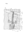
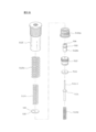
図1A~Eは、図示される実施形態において細長い円筒形の形状を有する管状上部本体又はハウジング102と、対応する形状を有する下部本体又は組立体116と、圧力調整システムの調整可能な圧力調整弁112との異なる部分の様々な図を示しており、これらの部分は、組み立てられると、本発明の実施形態に係る圧力調整装置100を提供する。多角形、楕円形などの他の形状も同様に使用可能であるため、本発明は円筒形/円形の断面形状に限定されない。
1A-E illustrate a tubular upper body or
概観すると、圧力調整装置100は、好ましくはステンレス鋼又はアルミニウムなどの耐食性超合金で形成される組立体116を含む。上部本体102及び組立体116はまた、合金の代わりに、蒸気ガス圧力調整に関連して使用するために適合性のある高強度の工学的熱可塑性プラスチック、セラミック又は他の材料で製造/成形されてもよい。本実施形態の組立体116は、円形断面を特徴とするベース116Aと、肩部を規定する上面と、肩部から中央に直交して突出する段付きの部分的に中空の軸116Bと、を含む。軸116Bは、本体102の相補的な段付き軸方向コア又はボア111に寸法的に適合し、ボア111に挿入されるように適合され、ボア111は、より狭いボアの中間部分111Bに向かって先細になり、ボアの上部部分111Aに拡張するより大きな直径の下部部分111Cを含む。
In overview,
軸116Bは、給電線134によって動力が供給される任意の電気的な加熱カートリッジ要素138と、は、加熱カートリッジ要素138のベースから突出し、電気及び制御吐出ポート129を介して組立体116を出る熱電対135によって感知される吐出物とを受け入れ、保持するための内部空洞136を含む。
図示される実施形態では、上部本体102は、ボア111の上部の上面106に形成された開口部107を特徴とする。一連のねじ切りされたプラグ114は、上面106の周囲環部104の周り及びその近くに配置される。プラグ114は、周囲環部104からボア111に向かって放射状に内向きに角度を付けるアクセスチャネル115を密封する。上面106はまた、軸方向にオフセットし、縦方向に突出し、弁を受け入れる5つの凹型開口部146を特徴とする。凹型開口部146は、開口部107の周りに配置され、縦方向に延在し、そして上部本体102の延長軸にほぼ平行である。各凹型開口部146は、圧力調整弁112を着座させて保持するように段付きで寸法設計されている(図4を参照)。
In the illustrated embodiment, the
図1Bは、組立体116が上部本体102の部分111A、B、C内に配置され、圧力調整弁112が各々の開口部146に着座している圧力調整装置100の断面斜視図を示す。図1Bの断面に示されるように、第1の圧力調整弁112は、半径方向に配向された蒸気試料通路109を介して蒸気試料入口108から蒸気試料を受け入れるように構成される。
FIG. 1B shows a cross-sectional perspective view of
蒸気ガス試料は、コネクタポート113Aで蒸気試料通路109を介して第1段階の圧力調整弁112に導かれる。以下に詳述するように、圧力調整弁112は蒸気ガス試料の圧力を低下させ、次に、蒸気ガス試料は、追加の減圧のために隣接する圧力調整弁112に連続的に導かれる一方で、任意選択の中央加熱カートリッジ要素138を介して任意に同時に熱制御される。最終段階の圧力調整弁112を出ると、現在分析装置の安全な圧力にある蒸気ガス試料は、管状上部本体102から蒸気試料通路142を通って蒸気試料出口110に導かれる。
The vapor gas sample is directed to first stage
圧力調整弁112の下部の構造及び配置を参照すると、圧力調整弁は、ばね圧に基づいて制御された軸方向調整を可能にするために、凹型開口部146を受け入れる弁に着座している。凹型開口部146は、段付きの構成で、上部平面106から開口部146内に、下部ボア118、直径方向に大きい中間ボア121及びより大きい上部ボア123を含む。圧力調整弁112は、組み合わせて、上方に付勢された、軸方向に配置された螺旋状圧縮弁軸ばね112Mと、張り出した円錐形弁軸突起112L-2を定義する上部肩部で終端する円筒形弁軸基部112L-1及びピストン112Gを感知するために弁座112J及び弁ガイド112Iを通って上向きに突出する弁軸先端112L-3に分割された弁軸112Lと、下方に付勢されたフラット/ベルビル/波感知ピストンアクチュエータばね112Fと、を特徴とする。上部肩部は、上方に付勢され、軸方向に配置された螺旋状圧縮弁軸ばね112Mのストッパーとして機能し、円錐形弁軸突起112L-2の下に弁軸112Lを巻き込む。弁軸先端112L-3の細長い部分は、円錐形弁軸突起112L-2の先細りの表面から感知ピストン112Gの底面まで軸方向に上向きに突出している。
Referring to the structure and arrangement of the lower part of the
弁座112J及び弁ガイド112Iは、中間ボア121内に配置され、Oリングなどの密封装置112Kで互いに密封され、それぞれ、弁軸先端112L-3及び蒸気ガス試料の通過を可能にする実質的に中央のチャネル127を有する。弁ガイド112Iは、合わせ穴131を介して管状上部本体102にボルト又はねじで留めることによって管状上部本体102に接続することができる。弁座112Jは、一方の面で下部ボア118に面し、他方の面で弁ガイド112Iに面し、弁座112J及び弁ガイド112Iの両方は中間ボア121全体を形成する。弁座112Jは、セラミック、エラストマー又はシリコーンなどの従属材料で構成でき、このような材料は、円錐形弁軸突起112L-2による実質的に中央のチャネル127の汚染又は密封を防止するのに役立つ。円錐形弁軸突起112L-2は、弁座112Jに圧縮されてワイパーとして機能するため、その形状による汚染を防止する。したがって、弁座112Jを通る中央のチャネル127は、弁ガイド112Iを通る中央のチャネル127よりも大きな直径を有し、円錐形弁軸突起112L-2による弁座112Jへの圧縮及びそれとの確実な拭き取り接触を可能にする。弁座112J及び弁ガイド112Iは、中間ボア121内の適切な位置に固定され、圧力調整弁112の動作中に移動しない。
上部ボア123は、例えばばねなどの軸方向に配置された感知ピストンアクチュエータ112Fを含み、感知ピストンアクチュエータ112Fは、ばね室112Cによって巻き込まれ、ねじ又はボルトなどの調整装置112Aから延在し、開口部146から上部ボア123の下部に配置された感知ピストン112Gまで突出している。圧力調整弁112は、任意の時点で、全開位置、調整位置及び全閉位置の3つの位置のうち1つにあり得る。圧力調整弁112は、圧力調整装置100が使用されず、下部ボア118内に圧力がないか又は非常に低い圧力が存在するとき、全開位置にある。したがって、この状態は、感知ピストンばね112Fによって加えられた圧力が下部ボア118に移動する任意の最小の流入蒸気ガス試料の圧力をはるかに超え、その結果、弁軸ばね112Mを介して弁軸112Lに加えられる軸方向の動きがほとんど又はまったくないときに存在する。これにより、円錐形弁軸突起112L-2と弁座112Jとの間にかなりのギャップをもたらす。
The
圧力調整装置100が使用され、流入蒸気ガス試料を調整しているとき、圧力調整弁112は調整位置にある。この状態が存在するために、感知ピストンばね112Fの設定に基づいて感知ピストンばね112Fによって感知ピストン112Gに加えられる圧力は、下部ボア118に移動する任意の流入蒸気ガス試料の圧力を相殺する。圧力調整弁112が調整位置にあり、感知ピストンばね112Fによって加えられる圧力が下部ボア118に移動する任意の流入蒸気試料の圧力を超える場合、感知ピストン112Gは、弁ガイド112Iの上面に接近しているが接触せず、円錐形弁軸突起112L-2を弁座112Jから変位させる弁軸先端112L-3に、直線的な下向きの圧力を加えない。この線形変位により、チャネル127を介する下部ボア118から上部ボア123への蒸気試料の流れが維持される。しかしながら、感知ピストンばね112Fによって加えられる圧力よりも大きい圧力を持つ流入蒸気ガス試料は、弁軸112Lが軸方向上方に移動するように推し進めることにより弁軸先端112L-3に感知ピストン112Gを弁ガイド112Iに接近するその位置からわずかに変位させ、また円錐形弁軸突起112L-2を軸方向上方に弁座112J内のチャネル127の一部に変位させる。したがって、圧力調整弁112は、動作中及び調整位置にあるとき、圧力が下流の分析装置で一定の流量で消費するために各段階で低下する定常状態に達するまで、各段階での圧力設定及び流入蒸気試料圧力に基づいて継続的に調整する。
When
図1Cは、調整位置にある圧力調整弁112の拡大図を示している。図示されているように、感知ピストン112Gによって弁軸先端112L-3に加えられる圧力よりも高い圧力を有する蒸気ガス試料119が下部ボア118に入り、それによって弁軸112Lが軸方向に上向きに移動し、弁軸先端112L-3が上部ボア123内で感知ピストン112Gを軸方向上方にわずかに変位させ、円錐形弁軸突起112L-2が弁座112J内のチャネル127の部分に食い込むようにする。図示されているように、弁座112Jと弁ガイド112Iとの間に形成された中央のチャネル127は、弁軸先端112L-3の直径よりもわずかに大きい直径を有し、このように、蒸気試料119が下部ボア118から中間ボア121を通って上部ボア123内のギャップ128に流入することができる。したがって、上部ボア123に入る任意の蒸気試料119は、下部ボア118と上部ボア123との間の圧力差、中央のチャネル127の限られた空間内の通路及び弁座112Jと円錐形弁軸突起112L-2との間の限られた通路サイズに基づいて減圧される。蒸気試料119によって感知ピストン112Gに加えられる圧力は感知ピストンばね112Fの弁設定と同じである一方、減圧された蒸気試料119はボア118、121及び123を通過し続ける。蒸気試料119の圧力が、感知ピストンばね112Fによって加えられる力と見合うほど大きくなくなった場合、圧力調整弁112は、より開放位置に移動し、感知ピストンばね112Fが感知ピストン112Gを変位させ、次に弁軸先端112L-3を介して円錐形軸突起112L-2を変位させて弁座112Jから離れるようにする。逆に、蒸気試料流れ119の圧力が高すぎる場合、円錐形弁軸突起112L-2が弁座112Jを遮断することによって蒸気の流れを妨げる。
FIG. 1C shows an enlarged view of the
したがって、圧力調整弁112が調整位置にある間に下部ボア118を出て上部ボア123のギャップ128へ向かう蒸気試料119は、相互接続チャネル144を介して予め選択された圧力で出て、さらなる圧力低下のために本体102内の次の段階の圧力調整弁112に導かれる。この構造及び動作により、圧力調整弁間の相互接続チャネル144からの過圧蒸気ガスの排出が不要となる。相互接続チャネル144に吐出される蒸気圧がすでに調整されたレベルに低下しているので、下流の調整弁組立体112への過圧蒸気吐出のためのベントの設置は不要であり、かつ望ましくない。結果として、開示された実施形態の非通気であり、より複雑でない構造が実現される。また、分析前に蒸気を放出すると、最終的な試料分析の完全性と精度を損なう。
Accordingly, the
圧力調整弁112は、弁の吐出が遮断され、出口圧力条件が満たされ、体積消費又は凝縮が存在しないとき(すなわち、下流の分析装置がオフになり、出口110で連続的に減圧させないとき)、全閉位置にある。換言すれば、遮断された流入蒸気試料によって形成された圧力は、逆方向に変換され、弁軸先端112L-3によって感知ピストンばね112Gに加えられる圧力に加えて、感知ピストン112Gに大きな圧力を加える。感知ピストン112Gへの圧力が増加して、感知ピストン112Gを上部ボア123内で軸方向に上方に変位させることにより、弁軸112Lが対応して軸方向に上方に変位し、弁座112J内に完全に着座して、チャネル127が完全に遮断される。
The
図2A~2Cは、蒸気試料119が蒸気試料通路109の下流から5つの段階を通って複数の圧力調整弁112及び対応する相互接続チャネル144を介して蒸気試料出口110に流れるときの蒸気試料119の流れを示している。この例では、圧力調整弁112が適切に較正され、調整装置112Aを介して適切な圧力設定が適用されるため、流入蒸気試料119は、各圧力調整弁112において、各圧力調整弁112を調整位置に押し進めるのに十分な圧力を有する。調整装置112Aは、ねじ切りされたばね室112C及び終端ナット112Bを介して開口部146内で軸方向に移動することにより、感知ピストンばね112Fに隣接するワッシャ112Eを変位させるように構成されている(図4を参照)。或いは、図1E及び3に示されているように、ねじ又はボルトなどの調整装置112Aは、管状上部本体102の上部平面106に直接隣接し、圧力設定を調整するために圧力調整弁112にねじ切りされるように構成されてもよい。この例では、調整装置112Aが必要とする空間が小さいため、圧力調整装置100の全体形状は小さくなる。しかしながら、図1A、1B、2及び3に示される調整装置112Aの構成とは異なり、この例では、製造コストを増加させる可能性がある、圧力調整弁のボア125内の追加のねじ切りが必要とされる。
FIGS. 2A-2C illustrate the
圧力調整装置100の特定の段階の圧力を調整するために、調整装置112Aは、ねじ切りされたばね室112Cを通って回転し、ワッシャ112Eを介して感知ピストンばね112Fを圧縮するか又はその圧縮を解くことにより隣接する感知ピストン112G上の感知ピストンばね112Fの圧力を増減して較正することができる。特定の段階における圧力設定が高いほど、より高い感知ピストンばね112F圧力に変換され、この圧力により、感知ピストン112Gは、弁軸先端112L-3を介して、円錐形弁軸突起112-L2をより制限の少ない位置に接近する弁座112Jに変位させる。したがって、図2A及び2Bに示されているように、段階1の圧力調整弁112の圧力設定は、段階2の圧力調整弁112の圧力設定よりも大きくなり、順に、段階5の圧力調整弁112の圧力設定が最も低くなる。
To adjust the pressure of a particular stage of
図1D及び1Eを参照すると、各段階での圧力設定は、対応する圧力調整弁112の出力で対応する相互接続チャネル144にそれぞれ接続された各々のアクセスチャネル115を介して設定及び検証することができる。段階5の圧力調整弁112の圧力設定を較正するために、段階5の圧力調整弁112から通路142に向かって出力された相互接続チャネル144内の圧力を、対応するアクセスチャネル115を介して測定する。図1Eは、段階1において圧力調整弁112の相互接続チャネル144に接続されたアクセスチャネル115を示している。アクセスチャネル115は、クラウンキャップ又はスクリューキャップなどのアクセスチャネル穴プラグ114によって塞がれているものとして示されている。しかしながら、段階1で圧力及び/又は温度を較正するために、アクセスチャネル穴プラグ114が取り外され、圧力センサー及び熱感知装置のいずれか又は両方がアクセスポート114に設置されて、コントローラへの追加の入力として機能することができる。したがって、蒸気試料119が圧力調整装置100を通過しているとき、圧力センサー及び/又は温度センサーは、相互接続チャネル144内でアクセスチャネル115を介して、段階1で圧力調整弁112を出る蒸気試料119の圧力/温度を検出する。次に、圧力調整弁112は、圧力センサーが蒸気試料投入ポート108に投入される蒸気試料119から所望の減圧読み取り値を検出するまで、調整装置112Aを介して調整することができる。次に、このプロセスは、対応するアクセスチャネル115で圧力センサーを使用して、各段階で連続する圧力調整弁112ごとに繰り返すことができる。これに対応して、熱ヒーターは、コントローラによって要求され操作されるとおり、蒸気試料温度を上昇又は低下させるように調整することができる。
Referring to FIGS. 1D and 1E, the pressure settings at each stage can be set and verified via each
圧力調整装置100を較正するための別の方法は、各アクセスチャネル115で同時に圧力を測定し、同時に各段階で圧力調整弁112を調整することである。圧力設定は、特定の用途又は特定のガスプロファイルに基づいて調整できる。もちろん、較正が実行されていないとき又は較正が完了したとき、自動化された圧力センサーを継続的に維持することが望まれない限り、アクセスチャネル穴プラグ114は、アクセスチャネル115を塞ぐために交換される。
Another method for calibrating the
異なる段階で圧力調整弁112の圧力設定を個別に調整する能力は、異なるプロファイルを有する様々なガスに使用できる圧力調整装置100に提供される。したがって、圧力調整装置100によって処理される特定の蒸気ガスプロファイルの熱力学的特性及び位相曲線に基づいて、各圧力調整弁112は、各段階において、蒸気ガス試料が位相曲線の2相領域に戻ったり、再び入ったりすることを許容しない低減レベルまで圧力を低下させるように較正することができる。各段階での低減は、組立体116、より具体的には、全ての減圧段階において露点凝縮/炭化水素露点低下を防ぐために必要な蒸気試料119の温度を一貫して維持する、放射状に取り囲む圧力調整弁112内の実質的に中央に配置された任意の加熱カートリッジ要素138によってさらに制御することができる。したがって、圧力調整装置100は、各用途又はガスプロファイルに対して異なる圧力調整装置を必要とするのではなく、様々な用途及び/又はガスプロファイルに対して経時的に動的に較正することができる。さらに、圧力調整装置100は、他の段階を動的に低く設定して圧力調整装置100に入る初期に低い圧力を相殺することができるので、第1の段階に入る特に高い最小量の初期圧力を必要としない。
The ability to individually adjust the pressure settings of
再び図2A及び2Bを参照し、そして一例として、対応する調整装置112A及びアクセスチャネル115を使用して圧力調整弁112が適切に較正されると、コネクタポート113Aで通路109を介して下部ボア118に投入される蒸気試料119は、段階1の圧力設定よりもより大きい圧力P0を有し、この圧力により弁軸先端112L-3を軸方向上方に移して感知ピストン112Gを変位させる。この変位により、円錐形弁軸突起112L-2が弁座112J内で軸方向上方に変位し、このように、中間ボア121及び上部ボア123内のチャネル127を通って導かれる蒸気試料119の流れを低下した圧力P1に制限し、この流れはその後に相互接続チャネル144を介して段階2に導かれる。次に、低下した圧力P1を有する蒸気試料119は、P1よりも低い圧力設定を有する段階2で圧力調整弁112の下部ボア118に入り、このように、蒸気試料119は、再び圧力調整弁112を通過して次の段階へ入ることができる。このプロセスは、低下した圧力P5を有する蒸気試料119が段階5で出口試料ポート110を介して圧力調整弁112を出て分析装置などの外部機器に送られるまで繰り返される。蒸気試料119は、放射状に配置された各々の圧力調整弁112で各段階を通って流れるので、組立体116の軸116B内の実質的に中央に配置された任意の加熱要素138を介して任意に熱制御され得る。したがって、蒸気試料119の圧力は、減圧手順における2相試料への露点の低下を回避するために、各段階で熱制御ならびに制御された減圧の対象となる。ウェルが各段階間で圧力及び温度の検知を統合すると、2相分離条件を作成して試料を危険にさらすことを回避するために、蒸気を位相曲線の外側の状態として維持する。特別に較正された圧力調整弁112及び実質的に中央に配置された加熱要素138によって提供される制御された環境により蒸気試料119が蒸気相領域に維持され、このように、試料の分析を汚染するか及び/又は下流の分析装置を損傷又は破壊する可能性のある凝縮又は露点低下のリスクが排除される。
Referring again to FIGS. 2A and 2B, and by way of example, once the
図示されていないが、本明細書において、調整装置112Aに機械的に接続され、かつ圧力センサーに電気的に接続されるか又は圧力センサーを含む多面的な較正ツールを用いて、手動で又はモーターで圧力調整装置100を自動的に較正することができることが、さらに企図される。そのような較正ツールは、圧力センサーを介して検出された圧力を計算し、モーターを使用して1つ又は複数の調整装置112Aをリアルタイムに自動的に調整して、各段階の最適な較正設定を提供することができる。或いは、圧力調整装置100は、調整装置112Aに接続されたモーターを含んでもよく、このモーターは、ローカル又はリモートでアクセスされて、1つ以上のアクセスチャネル115に接続された1つ以上の圧力センサーから処理された読み取り値に基づいて各段階で圧力設定を調整することができる。
Although not shown, it is possible herein to use a multifaceted calibration tool that is mechanically connected to the
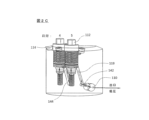
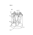
図3A及び3Bは、本発明の実施形態に係る組み立てられた圧力調整装置100の内部図を示している。図示されるように、圧力調整装置100は、相互接続チャネル144に接続された複数のアクセスチャネル115を含み、このように、圧力を測定して様々な段階を較正する能力を提供する。また、放射状に配置された圧力調整弁112内の加熱カートリッジ要素138(組立体軸116Bに配置されている)の実質的に中央の位置も示されている。蒸気ガス試料は、蒸気試料投入ポート108を介して圧力調整装置に入り、通路109を介して段階1の圧力調整弁112に導かれる。圧力調整装置が適切に較正されていると仮定すると、蒸気試料は各段階で圧力低下を引き起こす各圧力調整バルブ112を通って順次導かれるため、出口110を介して段階5の圧力調整弁112を出る蒸気試料は、クロマトグラフなどの感圧機器による分析に適した圧力を有する。
3A and 3B show internal views of an assembled
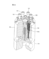
図4は、組み立てられると圧力調整装置100を形成する例示的な圧力調整システム101の分解図を示している。圧力調整システム101は、1つ以上の圧力調整弁112、管状上部本体102、組立体116及び加熱要素138を含む。1つ以上の圧力調整弁112は、終端ナット112B、ばね室112C及び室密封部112Dによりねじ切りされてワッシャ112Eに接触する調整装置112Aを含み、感知ピストンばね112Fによって感知ピストン112Gに対して加えられる力を増加させるか又は減少させることができる。弁軸ばね112M内に封入された弁軸112Lは、弁座112J及びガイド密封部112Kによって密封された弁ガイド112Iを通る動きを介して感知ピストンシート112Gに向かって反対の力を提供する。1つ以上の圧力調整弁112は、管状上部本体102内に軸方向に延在する1つ以上の開口部146内に取り付けられて、管状上部本体102の内部に段階的穴開け型ウェルを提供する。
FIG. 4 shows an exploded view of an exemplary
一例では、部分111Bは、放射状に穴開けされた蒸気試料投入ポート108及び吐出ポート110の近くの本体102の底部から穴開けすることによって管状上部本体102内に形成される(図1Bを参照)。部分111Bは、その軸方向の長さに沿ってその中点でほぼ先細になるように形成される。開口部107は、管状上部本体102の上部平面106から別個に穿設されて、部分111Aを形成して穴開けされた部分111Bと接続することができる。この例における開口部107は、部分111Aの直径が開口部107の真下に形成された部分111Bの直径よりも大きいため、上部平面106から形成されている。部分111Aが部分111Bと接触する時点で、組立体密封部を使用して、組立体116を管状上部本体102内に挿入したときに密封する。これにより、管状上部本体102の中央内部に加熱カートリッジ要素138を維持し、部分111Bによって形成されるテーパーに対して軸116Bを維持することによって、最大の熱伝達が保証される。
In one example,
組立体116は、組立体116のベース116Aから組立体軸116B内に穴開けされて任意の加熱カートリッジ要素138が挿入される内部空洞136を含む。空洞は、接触面積を増加させ、本体102への熱エネルギー伝達を強化するために、円筒形又はテーパー状であってもよい。給電線134及び熱電対135は、組立体116に放射状に穴開けされた制御吐出ポート129を介して挿入され、内部空洞136を介して加熱カートリッジ要素138に接続されてもよい。熱電対135は、比例積分微分(PID)コントローラ及び/又はAllen Bradley 850シリーズPLC又は同等のコントローラなどのプログラマブルロジックコントローラ(PLC)(図示せず)に接続されて、信号フィードバック及び圧力調整装置100の制御を提供することができる。加熱カートリッジ要素138、給電線134及び熱電対135が組立体116内に囲まれると、組立体116のベース116Aに穴開けされた開口部は、閉じたシステムを提供するために、雌ねじ切りされたプラグで閉じられる。安全のために、プラグは、ATEX規格などの1つ以上の該当する規格に従って防爆とすることができる。
組み立てられた圧力調整装置100は、製造コストが低く、試料調整機器内のより小さな領域で圧力調整装置100を使用することを可能にするコンパクトな設計を提供する。本明細書において説明したように、圧力調整装置100は、測定されるガスの特定の用途又はプロファイルに基づいて動的に調整され得るため、様々な異なる用途に使用することができる。さらに、直列に接続された放射状に配置された圧力調整弁112は、垂直に設計された多段階レギュレータに一般的に関連する、重力によって生じる問題を回避する。
The assembled
図5Aは、調整弁組立体の代替の実施形態を示している。この実施形態は、より高い開始圧力、例えば、41300kPa(6000psi)~69000kPa(10.000psi)以上での試料のために流入蒸気試料をより高度に減圧するために提供される。高圧レギュレータの実施形態は、上記の実施形態と本質的に変わらないレギュレータケース102及びベース116を含む。第3~第5の調整弁112は、同様に、前述のものから変更されないままである。しかしながら、少なくとも第1の圧力調整弁、そして好ましくは第2の圧力調整弁組立体512は異なる。高圧の実施形態は、入れ子型と分岐型の感知ピストン530及び少なくとも1つのより重い感知ピストンアクチュエータばねを特徴とする。
FIG. 5A shows an alternative embodiment of a regulator valve assembly. This embodiment provides for higher depressurization of the incoming vapor sample for samples at higher starting pressures, eg, 41,300 kPa (6000 psi) to 69,000 kPa (10,000 psi) or higher. The high pressure regulator embodiment includes a
高圧弁組立体の一実施形態は図5Bに示されている。図示されているように、高圧弁の実施形態は、寸法的に弁組立体112に適合するが、2成分感知ピストン512G構造を組み込み、このような構造は、本質的に、外側シェルシリンダ512Goに摺動可能に入れ子にされた内側コアシリンダ要素512Giを確立して内側コアシリンダ要素512Giと外側シェルシリンダ512Goとの間の相対的な軸方向の動きを可能にする。シリンダ要素512Gi及び512Goは、蒸気漏れを防止するためにそれらの外面の周りに配置された1つ以上の密封リング532を含んでもよい。また、高圧減圧配置においては、図4に示された感知ピストンの下に配置されたワッシャ112Eが不要となる。ワッシャ112が不要になるため、下方に付勢されたより重い感知ピストンアクチュエータばね、又は好ましくは図5Bに示されるように、二重ばね配置の使用が可能になる。二重ばねの構造は、ばね室512Cに着座する外側ばね512Fo内に入れ子にされた内側ばね512Fiを含む。以下に配置される場合、少なくとも内側ばねは、ばね室512Cの内径よりも小さい直径を有するワッシャ530である。一実施形態では、内側ばね512Fiは、ディスク状ワッシャ530に直接当たり、その結果、中心の内側コアシリンダ512Giの直径を効果的に拡大して、内側ばね512Fiから下向きのばね力を集中させる。この力は、内側コアシリンダ512Giを介して変換され、弁軸先端512L-3に伝達される。外側ばね512Foは、感知ピストン512Gの外側シェルシリンダ512Goの上面に直接当たってもよい。
One embodiment of a high pressure valve assembly is shown in FIG. 5B. As shown, the high pressure valve embodiment is dimensionally matched to
別の実施形態では、ワッシャ530は、直径がばね室512Cの内径全体にわたって実質的に延在し、その結果、内側ばね512Fi及び外側ばね512Foの両方と直接接触する。ワッシャ530の直径が外側ばね512Foの外径に対応する場合、最大ばね力が両方のばねによって感知ピストンに加えられる。より小さな直径のワッシャを使用すると、ばねとの接触が少なくなるため、ワッシャにかかるばね力の圧力が減少する。この機能により、所望の減圧調整を実現するための設計の柔軟性が高まる。
In another embodiment,
換言すれば、この配置は、ばね512Fi及び512Foの圧縮ばね力全体を、ワッシャ530を介してより小さな直径の内側コア512Giに向けることにより、その有効圧縮及び上方に突出する弁軸先端512L-3に下方に向けられた力を増強させ、この場合、感知ピストンの内側コアピストンシリンダ512Giに接触して押し付けることによって、より高い開始圧力で効果的な圧力調整を提供する。
In other words, this arrangement directs the entire compression spring force of springs 512Fi and 512Fo through
構造的に、ワッシャ530は、ステンレス鋼又は代替の剛性の強い材料、例えば、セラミック、非反応性金属合金などから形成され、好ましくは、中央の開口部532の中心にある受け入れノッチを含み、この受け入れノッチは、ばね室512C内のワッシャ530を位置的に安定させるために、内側コアピストンシリンダ512Giのほぼ平坦な上面の上に突出する突起534を受け入れてそれと協調するように寸法設計されている。
Structurally, the
前述のように、高圧弁組立体の寸法が前述の弁組立体の実施形態に対応する場合、ハウジングの口径の標準化が達成されるが、状況に応じて、必要な程度の強化された圧力調整を達成するために必要な場合、より大きなサイズの高圧調整弁組立体を収容するために、弁を受け入れる最初の2つの凹型開口部の口径を拡大することができる。 As mentioned above, if the dimensions of the high-pressure valve assembly correspond to the embodiments of the valve assembly described above, standardization of the housing caliber is achieved, but depending on the situation, the required degree of enhanced pressure regulation If necessary to accomplish this, the diameter of the first two recessed openings receiving the valves can be enlarged to accommodate a larger sized high pressure regulating valve assembly.
上述した追加又は代替の詳細のいずれかを組み込んだ装置又は方法は、以下の特許請求の範囲及びその同等物に基づいて決定される本発明の範囲に含まれることが当業者に理解されるであろう。例えば、5つのアクセスチャネル115、5つの開口部146及び5つの対応する圧力調整弁112が示されているが、本明細書において、当業者によって理解されるように、より少ない又はより多くのこれらの機構を実装して異なる構成を提供することができると考えられる。さらに、本明細書において論じられる例示的な実施において、蒸気ガス試料は、液体試料を蒸気形態に気化させた気化器装置の吐出物から受け入れられる。しかしながら、圧力調整装置100は、天然ガスから直接的に、又はガス試料調整システム内の上流又は下流の他の箇所にある他のタイプの機器から受け入れられた蒸気ガス試料を調整するために使用することができる。
It will be appreciated by those skilled in the art that apparatus or methods incorporating any of the additional or alternative details described above are within the scope of the invention as determined by the following claims and their equivalents. Probably. For example, although five
本発明の他の態様、目的及び利点は、図面及び開示を与えられた当業者には明らかであるはずである。 Other aspects, objects, and advantages of the invention will be apparent to those skilled in the art given the drawings and disclosure.
本発明は、多段階圧力調整システムを提供するために有用であり、ガス試料圧力調整システムを通過する蒸気ガスの圧力を低下させるための装置及び関連する方法を用いた天然ガス試料の採取における使用に特に適し、ガス試料圧力調整システムを通過する蒸気ガスの圧力を低下させる多段階圧力調整システム、装置及び関連する方法である。このシステム及び方法は、非通気アレイに配置された一連の較正可能な圧力調整弁組立体を含む、必要に応じて加熱されたハウジングに依存し、各組立体は、通過中の露点の低下を回避しながら、蒸気試料を予め設定された減圧で下流の分析装置に送るために、投入された蒸気試料の圧力を選択された減圧に低下させるように構成されている。 The present invention is useful for providing a multi-stage pressure regulation system for use in natural gas sample collection using an apparatus and associated method for reducing the pressure of vapor gas passing through the gas sample pressure regulation system. A multi-stage pressure regulation system, apparatus and related method for reducing the pressure of a vapor gas passing through a gas sample pressure regulation system. The system and method relies on an optionally heated housing containing a series of calibratable pressure regulating valve assemblies arranged in an unvented array, each assembly providing dew point reduction during passage. The vapor sample is configured to reduce the pressure of the input vapor sample to a selected reduced pressure while avoiding delivery of the vapor sample to a downstream analytical device at a preset reduced pressure.
100 圧力調整装置
102 上部本体、レギュレータケース
104 周囲環部
106 上面
107 開口部
108 蒸気試料投入ポート
109 蒸気試料通路
110 蒸気試料吐出ポート
111 ボア
111A 上部部分
111B 中間部分
111C 下部部分
112 圧力調整弁
112A 調整装置
112B 終端ナット
112C、512C ばね室
112D 室密封部
112E 、530ワッシャ
112F 感知ピストンばね
112G 感知ピストン
112I 弁ガイド
112J 弁座
112K 密封装置、ガイド密封部
112L 弁軸
112L-1 弁軸基部
112L-2 弁軸突起
112L-3、512L-3 弁軸先端
112M 弁軸ばね
113A コネクタポート
114 プラグ
115 アクセスチャネル
116 組立体
116A ベース
116B 軸
118 下部ボア
119 蒸気試料
121 中間ボア
123 上部ボア
125 圧力調整弁のボア
127 チャネル
128 ギャップ
129 制御吐出ポート
131 合わせ穴
134 給電線
135 熱電対
136 内部空洞
138 加熱カートリッジ要素
142 蒸気試料通路
144 相互接続チャネル
146 開口部
512 第2の圧力調整弁組立体
512Fo 外側ばね
512Fi 内側ばね
512G 感知ピストン
512Gi 内側コアシリンダ
512Go 外側シェルシリンダ
532 密封リング、中央開口部
534 突起
100
Claims (20)
ハウジングと、
ハウジングの中心軸に沿ってほぼ縦方向に配置されたコアと、
ハウジング内に一体的に形成された蒸気試料通路に接続された蒸気試料投入ポートと、
ハウジングの上面にある複数の非通気開口部であって、それぞれコアの周囲に配置され、少なくとも1つの他の非通気開口部に隣接し、選択された断面寸法を有し、ハウジングの延長方向に延在し、そして前記ハウジング内に一体的に形成され、隣接する非通気開口部に接続された相互接続チャネルによって接続された非通気開口部と、
複数の圧力調整弁であって、それぞれ非通気開口部の選択された断面寸法に対応する断面寸法を有し、蒸気試料を選択された調整圧力で、接続された相互接続チャネルを介して、隣接する下流の圧力調整弁に送るために、非圧力調整モードと圧力調整モードとの間で切り替え可能であり、そして減圧段階を確立し、弁軸、感知ピストン及び感知ピストンアクチュエータを含む圧力調整弁と、
減圧された蒸気試料吐出ポートと、を含むことを特徴とする圧力調整システム。 A pressure regulation system for stepwise depressurization of a vapor sample, the system comprising:
housing and
a core arranged substantially longitudinally along the central axis of the housing;
a steam sample input port connected to a steam sample passage integrally formed within the housing;
a plurality of non-vented openings in the top surface of the housing, each disposed around the core, adjacent at least one other non-vented opening, having selected cross-sectional dimensions and extending in the direction of extension of the housing ; a non-venting opening extending through and connected by an interconnecting channel integrally formed within the housing and connected to an adjacent non-venting opening ;
a plurality of pressure regulating valves each having a cross-sectional dimension corresponding to a selected cross-sectional dimension of the unvented opening, the vapor sample being controlled at a selected regulating pressure through an adjacent interconnecting channel; is switchable between a non-pressure regulating mode and a pressure regulating mode, and establishes a pressure-reducing stage to feed a downstream pressure regulating valve, including a valve stem, a sensing piston and a sensing piston actuator. ,
A pressure regulation system comprising: a reduced pressure vapor sample discharge port.
圧力調整システムは、複数の圧力調整弁を通過する蒸気試料を加熱するように構成された、軸内に配置された加熱装置をさらに含む、請求項1に記載の圧力調整システム。 The housing includes a base and an axis disposed generally perpendicular to the base and extending axially from the base and formed to substantially match the dimensions of the core and extending axially from a central portion of the base. further characterized by an assembly having;
2. The pressure regulation system of claim 1, further comprising a heating device disposed within the shaft configured to heat a vapor sample passing through the plurality of pressure regulation valves.
圧力調整装置のハウジング内に形成された蒸気試料入口を介して蒸気試料を投入するステップと、
ハウジングに一体的に形成された第1の無通気開口部内に配置された調整可能な第1の圧力調整弁組立体に、蒸気試料を選択的に導き、第1の無通気開口部は、ハウジングに一体的に形成された第2の無通気開口部内に配置された隣接する第2の圧力調整弁組立体に、相互接続チャネルによって接続されるステップと、
蒸気試料の圧力を所定の量に低下させ、ハウジングに一体的に形成された第2の無通気開口部内に配置された隣接する調整可能な第2の圧力調整弁組立体に蒸気試料を送り、第2の無通気開口部は、ハウジングに一体的に形成された第3の無通気開口部内に配置された隣接する第3の圧力調整弁組立体に、相互接続チャネルによって接続されるステップと、
蒸気試料の圧力を第2の所定の量に低下させ、隣接する調整可能な第3の圧力調整弁組立体に蒸気試料を送るステップと、
蒸気試料が第1、第2及び第3の調整弁組立体を通過するときに試料を蒸気相に維持するステップと、を含むことを特徴とする方法。 A method for reducing the pressure of a vapor sample by a plurality of calibrated stepwise depressurization stages, the method comprising:
introducing a vapor sample through a vapor sample inlet formed in the housing of the pressure regulator;
A vapor sample is selectively directed to an adjustable first pressure regulating valve assembly disposed within a first non-vented opening integrally formed in the housing, the first non-vented opening being integrally formed in the housing. connected by an interconnecting channel to an adjacent second pressure regulating valve assembly disposed within a second unvented opening integrally formed with the second pressure regulating valve assembly;
reducing the pressure of the vapor sample to a predetermined amount and directing the vapor sample to an adjacent adjustable second pressure regulating valve assembly disposed within a second unvented opening integrally formed in the housing; the second unvented opening is connected by an interconnecting channel to an adjacent third pressure regulating valve assembly disposed within a third unvented opening integrally formed in the housing;
reducing the pressure of the steam sample to a second predetermined amount and directing the steam sample to an adjacent adjustable third pressure regulating valve assembly;
maintaining the vapor sample in the vapor phase as the vapor sample passes through the first, second and third regulating valve assemblies.
第1の表面、第2の反対面及び蒸気試料投入ポート及び蒸気試料吐出ポートを組み込んだ周縁面を備えたレギュレータ本体、並びにレギュレータ本体の熱安定性を維持する熱制御手段と、
周縁面に近接する第1の表面の周りに配置された複数の非通気開口部であって、それぞれ、選択された断面寸法を有し、第1の表面と第2の表面との間に延在し、ハウジング内に一体的に形成された相互接続チャネルにより接続され、隣接する非通気開口部に接続された非通気開口部と、
調整可能な圧力調整のための調整可能な弁組立体手段であって、各非通気開口部内に含まれるように寸法設定されて、蒸気試料の蒸気圧を所定の最大値に調整し、蒸気試料が所定の範囲外の圧力で、相互接続チャネルを介して隣接する弁組立体手段を通過するのを防止して、蒸気試料を蒸気相に維持しながら、蒸気試料の連続的で段階的な減圧のための手段を確立する調整可能な弁組立体手段と、を特徴とする天然ガス蒸気試料の減圧用の圧力調整システム。 A pressure regulation system for depressurizing a natural gas vapor sample, the system comprising:
a regulator body having a first surface, a second opposing surface and a peripheral surface incorporating a vapor sample input port and a vapor sample outlet port; and thermal control means for maintaining thermal stability of the regulator body;
a plurality of non-venting openings disposed about the first surface proximate the peripheral surface, each having a selected cross-sectional dimension and extending between the first surface and the second surface; a non-vented opening connected by an interconnecting channel integrally formed within the housing and connected to an adjacent non-vented opening;
adjustable valve assembly means for adjustable pressure regulation, the means being dimensioned to be contained within each unvented opening for regulating the vapor pressure of the vapor sample to a predetermined maximum value; Continuous step-up of the vapor sample while maintaining the vapor sample in the vapor phase by preventing the vapor sample from passing through the interconnecting channel through the adjacent valve assembly means at pressures outside the predetermined range. A pressure regulation system for reducing the pressure of a natural gas vapor sample, comprising: an adjustable valve assembly means for establishing a means for reducing the pressure;
20. A pressure regulation system for depressurization of natural gas vapor samples according to claim 19, further characterized by intelligent automatic control of each adjustable valve assembly means.
Applications Claiming Priority (3)
| Application Number | Priority Date | Filing Date | Title |
|---|---|---|---|
| US201962904022P | 2019-09-23 | 2019-09-23 | |
| US62/904,022 | 2019-09-23 | ||
| PCT/US2020/051728 WO2021061542A2 (en) | 2019-09-23 | 2020-09-21 | Adjustable multistage pressure reducing regulator |
Publications (2)
| Publication Number | Publication Date |
|---|---|
| JP2022548389A JP2022548389A (en) | 2022-11-18 |
| JP7378599B2 true JP7378599B2 (en) | 2023-11-13 |
Family
ID=74880820
Family Applications (1)
| Application Number | Title | Priority Date | Filing Date |
|---|---|---|---|
| JP2022518000A Active JP7378599B2 (en) | 2019-09-23 | 2020-09-21 | Adjustable multi-stage pressure reducing regulator |
Country Status (17)
| Country | Link |
|---|---|
| US (2) | US11144078B2 (en) |
| EP (1) | EP4034960A4 (en) |
| JP (1) | JP7378599B2 (en) |
| KR (1) | KR20220061157A (en) |
| CN (1) | CN114514487A (en) |
| AU (1) | AU2020356369B2 (en) |
| BR (1) | BR112022005542A2 (en) |
| CA (1) | CA3151167C (en) |
| CL (1) | CL2022000686A1 (en) |
| CO (1) | CO2022003347A2 (en) |
| EC (1) | ECSP22022336A (en) |
| GB (2) | GB2617744B (en) |
| IL (1) | IL291588A (en) |
| MX (1) | MX2022003310A (en) |
| PE (1) | PE20221113A1 (en) |
| SA (1) | SA522432012B1 (en) |
| WO (1) | WO2021061542A2 (en) |
Families Citing this family (4)
| Publication number | Priority date | Publication date | Assignee | Title |
|---|---|---|---|---|
| USD973849S1 (en) * | 2021-03-16 | 2022-12-27 | Mustang Sampling, Llc | Pipe fitting |
| US11372431B1 (en) * | 2021-05-10 | 2022-06-28 | Bayotech, Inc. | Multi-function three-stage pressure regulator |
| US11604125B1 (en) | 2022-03-07 | 2023-03-14 | Mustang Sampling, Llc | Liquid gas sample vaporizer conditioning system and method |
| CN117515179B (en) * | 2024-01-05 | 2024-04-02 | 瑞星久宇燃气设备(成都)有限公司 | Asynchronous lever structure voltage regulator and parameter acquisition method |
Citations (1)
| Publication number | Priority date | Publication date | Assignee | Title |
|---|---|---|---|---|
| US1957972A (en) | 1930-03-11 | 1934-05-08 | Mills Ellsworth Luther | Multistage regulator |
Family Cites Families (50)
| Publication number | Priority date | Publication date | Assignee | Title |
|---|---|---|---|---|
| US2057133A (en) | 1929-11-30 | 1936-10-13 | Union Carbide & Carbon Corp | Multistage pressure regulator |
| US2057150A (en) | 1932-03-21 | 1936-10-13 | Union Carbide & Carbon Corp | Two-stage pressure regulator |
| US2160849A (en) | 1937-04-12 | 1939-06-06 | Arthur J Fausek | Multistage pressure regulator |
| US2306060A (en) | 1940-10-31 | 1942-12-22 | Union Carbide & Carbon Corp | Pressure regulating and reducing apparatus |
| US2672891A (en) | 1948-02-07 | 1954-03-23 | Arthur J Fausek | Pressure regulator |
| US2642701A (en) | 1948-12-15 | 1953-06-23 | Stephenson Corp | Two-stage gas pressure regulator |
| US2816561A (en) | 1952-08-11 | 1957-12-17 | Wallace O Leonard Inc | Pressure reducing valve |
| FI72383C (en) | 1983-05-20 | 1987-05-11 | Halton Oy | STROEMNINGSREGULATOR. |
| FR2594972B1 (en) | 1986-01-15 | 1988-10-07 | Imaje Sa | PRESSURE REGULATOR WITH INTEGRATED SENSOR |
| US5285810A (en) | 1993-02-11 | 1994-02-15 | Itt Corporation | Pressure-reducing regulator for compressed natural gas |
| CA2131108C (en) * | 1994-08-30 | 2005-06-07 | Stephen A. Carter | Two-stage pressure regulator |
| CA2136699C (en) | 1994-11-25 | 2003-09-30 | Stephen A. Carter | Three-stage gas pressure regulator |
| US5595209A (en) | 1995-03-29 | 1997-01-21 | Airtrol Components Inc. | Fluid pressure regulator establishing a stable output fluid pressure |
| US5841036A (en) | 1996-08-22 | 1998-11-24 | Mayeaux; Donald P. | Modular sample conditioning system |
| GB9724168D0 (en) | 1997-11-14 | 1998-01-14 | Air Prod & Chem | Gas control device and method of supplying gas |
| US6116269A (en) | 1998-07-07 | 2000-09-12 | Fasco Controls Corporation | Solenoid pressure transducer |
| US6722388B1 (en) * | 2000-02-28 | 2004-04-20 | Mcaden Robert A. | Multiple pressure regulator |
| US7080655B2 (en) | 2003-03-04 | 2006-07-25 | American Air Liquide, Inc | Regulator for low concentration corrosive and reactive gases |
| AU2005260719B2 (en) | 2004-06-30 | 2010-07-22 | Mustang Sampling, Llc | Gas sample conditioning system |
| US7565911B2 (en) | 2004-07-06 | 2009-07-28 | Absolute Air, Inc. | Two stage regulator method and apparatus |
| CN102853253A (en) | 2005-02-22 | 2013-01-02 | 玛氏唐森普林有限公司 | Liquid gas vaporization and measurement system and method |
| US8056399B2 (en) | 2005-02-22 | 2011-11-15 | Mustang Sampling, Llc | Liquid gas vaporization and measurement system and method |
| US7341074B2 (en) | 2005-05-19 | 2008-03-11 | Gm Global Technology Operations, Inc. | Multi-stage pressure regulator |
| US7743641B2 (en) | 2005-09-02 | 2010-06-29 | Abb Inc. | Compact field-mountable gas chromatograph with a display screen |
| US20070215220A1 (en) | 2006-03-20 | 2007-09-20 | Bannon Thomas K | System for direct transfer of gas from a supply source to a portable cylinder and method for same |
| US8448662B1 (en) | 2006-12-07 | 2013-05-28 | The Paul R. Beswick 2008 Revocable Trust | High inlet pressure three-stage pressure regulator |
| US20090071548A1 (en) | 2007-09-14 | 2009-03-19 | Daryll Duane Patterson | Modular in-line fluid regulators |
| CA2853841C (en) | 2008-04-30 | 2015-07-14 | Daniel Measurement And Control, Inc. | Apparatus and method for proving at low temperatures |
| US8220479B1 (en) | 2008-06-03 | 2012-07-17 | A+ Manufacturing LLC | Multi-stage ratio pressure regulator system |
| US7752919B2 (en) | 2008-07-09 | 2010-07-13 | Daniel Measurement And Control, Inc. | System and method of an acoustic flow meter with dual flow measurements |
| US9535427B2 (en) | 2009-01-21 | 2017-01-03 | Tescom Corporation | Temperature-controlled pressure regulators |
| US8544343B2 (en) | 2010-11-19 | 2013-10-01 | Cameron International Corporation | Chordal gas flowmeter with transducers installed outside the pressure boundary |
| CN201902830U (en) | 2010-12-10 | 2011-07-20 | 苏建都 | Pipeline gas pressure regulator internally provided with safety protecting device and warning sign |
| CN201980868U (en) | 2010-12-31 | 2011-09-21 | 巨力索具股份有限公司 | Multi-stage regulator |
| US9310812B2 (en) | 2012-10-12 | 2016-04-12 | Illinois Tool Works Inc. | Multi-stage pressure regulator and method for fluid pressure regulation |
| US9285299B2 (en) | 2012-11-26 | 2016-03-15 | Mustang Sampling Llc | Natural gas liquid pressure regulating vaporizer sampling system |
| US9588024B1 (en) | 2013-03-05 | 2017-03-07 | A+ Manufacturing, Llc | Stacked modular conditioning system and method |
| US9562833B2 (en) | 2013-03-15 | 2017-02-07 | Mustang Sampling Llc | Composite gas sampling system |
| US10641687B1 (en) | 2013-03-15 | 2020-05-05 | Mayeaux Holding, Llc | Wet gas sample probe, vaporizing regulator, and methods associated therewith |
| CN203274863U (en) | 2013-06-26 | 2013-11-06 | 北京聚雅科技有限公司 | High-pressure natural gas flowmeter calibrating device |
| JP6590818B2 (en) | 2014-02-12 | 2019-10-16 | ムスタング サンプリング, エルエルシーMustang Sampling, Llc | Natural gas liquid sample collection, vaporization and pressure regulation system |
| JP2016001455A (en) | 2014-05-21 | 2016-01-07 | 愛三工業株式会社 | Fuel supply system and decompression device |
| US10126214B1 (en) | 2014-07-21 | 2018-11-13 | Mayeaux Holding, Llc | Wet gas sampling system and method therefore |
| JP2016184259A (en) | 2015-03-26 | 2016-10-20 | 愛三工業株式会社 | Decompression device |
| US10078035B2 (en) | 2015-09-18 | 2018-09-18 | Mustang Sampling, Llc | Post-probe upstream metering pump for insuring NGL phase change completion in sample conditioning |
| JP2017079026A (en) | 2015-10-22 | 2017-04-27 | 愛三工業株式会社 | Pressure adjustment valve |
| US10161909B2 (en) | 2015-10-29 | 2018-12-25 | Mustang Sampling Llc | Steady state fluid flow verification for sample takeoff |
| US9989978B2 (en) | 2016-01-21 | 2018-06-05 | Itt Manufacturing Enterprises Llc | Natural gas pressure regulator having adjustable valve seat |
| WO2017205670A1 (en) | 2016-05-26 | 2017-11-30 | Sko Flo Industries, Inc. | Multi-stage flow control assemblies |
| US10613006B1 (en) | 2018-09-24 | 2020-04-07 | Mustang Sampling, LLC. | Liquid vaporization device and method |
-
2020
- 2020-09-18 US US17/025,476 patent/US11144078B2/en active Active
- 2020-09-21 CA CA3151167A patent/CA3151167C/en active Active
- 2020-09-21 PE PE2022000464A patent/PE20221113A1/en unknown
- 2020-09-21 CN CN202080068507.4A patent/CN114514487A/en active Pending
- 2020-09-21 AU AU2020356369A patent/AU2020356369B2/en active Active
- 2020-09-21 WO PCT/US2020/051728 patent/WO2021061542A2/en unknown
- 2020-09-21 BR BR112022005542A patent/BR112022005542A2/en unknown
- 2020-09-21 GB GB2310421.9A patent/GB2617744B/en active Active
- 2020-09-21 GB GB2203560.4A patent/GB2602412B/en active Active
- 2020-09-21 MX MX2022003310A patent/MX2022003310A/en unknown
- 2020-09-21 JP JP2022518000A patent/JP7378599B2/en active Active
- 2020-09-21 EP EP20867424.2A patent/EP4034960A4/en active Pending
- 2020-09-21 KR KR1020227011211A patent/KR20220061157A/en not_active Application Discontinuation
-
2021
- 2021-09-07 US US17/467,842 patent/US11573582B2/en active Active
-
2022
- 2022-03-21 SA SA522432012A patent/SA522432012B1/en unknown
- 2022-03-21 CL CL2022000686A patent/CL2022000686A1/en unknown
- 2022-03-22 IL IL291588A patent/IL291588A/en unknown
- 2022-03-23 CO CONC2022/0003347A patent/CO2022003347A2/en unknown
- 2022-03-23 EC ECSENADI202222336A patent/ECSP22022336A/en unknown
Patent Citations (1)
| Publication number | Priority date | Publication date | Assignee | Title |
|---|---|---|---|---|
| US1957972A (en) | 1930-03-11 | 1934-05-08 | Mills Ellsworth Luther | Multistage regulator |
Also Published As
| Publication number | Publication date |
|---|---|
| CO2022003347A2 (en) | 2022-07-08 |
| GB2602412B (en) | 2023-10-18 |
| GB2602412A (en) | 2022-06-29 |
| US11573582B2 (en) | 2023-02-07 |
| WO2021061542A3 (en) | 2021-07-15 |
| EP4034960A4 (en) | 2024-05-08 |
| US11144078B2 (en) | 2021-10-12 |
| AU2020356369A1 (en) | 2022-04-07 |
| BR112022005542A2 (en) | 2022-08-30 |
| GB202203560D0 (en) | 2022-04-27 |
| CL2022000686A1 (en) | 2022-10-14 |
| SA522432012B1 (en) | 2022-11-03 |
| US20210405668A1 (en) | 2021-12-30 |
| GB2617744A (en) | 2023-10-18 |
| AU2020356369B2 (en) | 2023-05-18 |
| PE20221113A1 (en) | 2022-07-12 |
| ECSP22022336A (en) | 2022-06-30 |
| CN114514487A (en) | 2022-05-17 |
| JP2022548389A (en) | 2022-11-18 |
| US20230096619A1 (en) | 2023-03-30 |
| EP4034960A2 (en) | 2022-08-03 |
| CA3151167A1 (en) | 2021-04-01 |
| GB2617744B (en) | 2024-04-24 |
| CA3151167C (en) | 2023-10-17 |
| WO2021061542A2 (en) | 2021-04-01 |
| IL291588A (en) | 2022-05-01 |
| MX2022003310A (en) | 2022-06-16 |
| KR20220061157A (en) | 2022-05-12 |
| US20210089062A1 (en) | 2021-03-25 |
Similar Documents
| Publication | Publication Date | Title |
|---|---|---|
| JP7378599B2 (en) | Adjustable multi-stage pressure reducing regulator | |
| KR101666114B1 (en) | Temperature-controlled pressure regulators | |
| US9535427B2 (en) | Temperature-controlled pressure regulators | |
| AU2019350570B2 (en) | Liquid vaporization device and method | |
| US10976222B2 (en) | In-line thermal isolator for liquid sample conditioning | |
| KR20110132403A (en) | In-line pressure regulators | |
| US11971733B2 (en) | Adjustable multistage pressure reducing regulator | |
| US20150014562A1 (en) | Low volume, pressure assisted, stem and seat vent valve and associated methods | |
| US9546739B2 (en) | Modular solenoid valve kits and associated methods |
Legal Events
| Date | Code | Title | Description |
|---|---|---|---|
| A621 | Written request for application examination |
Free format text: JAPANESE INTERMEDIATE CODE: A621 Effective date: 20220518 |
|
| A977 | Report on retrieval |
Free format text: JAPANESE INTERMEDIATE CODE: A971007 Effective date: 20230630 |
|
| A131 | Notification of reasons for refusal |
Free format text: JAPANESE INTERMEDIATE CODE: A131 Effective date: 20230711 |
|
| A521 | Request for written amendment filed |
Free format text: JAPANESE INTERMEDIATE CODE: A523 Effective date: 20231011 |
|
| TRDD | Decision of grant or rejection written | ||
| A01 | Written decision to grant a patent or to grant a registration (utility model) |
Free format text: JAPANESE INTERMEDIATE CODE: A01 Effective date: 20231024 |
|
| A61 | First payment of annual fees (during grant procedure) |
Free format text: JAPANESE INTERMEDIATE CODE: A61 Effective date: 20231031 |
|
| R150 | Certificate of patent or registration of utility model |
Ref document number: 7378599 Country of ref document: JP Free format text: JAPANESE INTERMEDIATE CODE: R150 |