JP7376460B2 - vacuum cleaner - Google Patents

vacuum cleaner Download PDF

Info

Publication number
JP7376460B2
JP7376460B2 JP2020199282A JP2020199282A JP7376460B2 JP 7376460 B2 JP7376460 B2 JP 7376460B2 JP 2020199282 A JP2020199282 A JP 2020199282A JP 2020199282 A JP2020199282 A JP 2020199282A JP 7376460 B2 JP7376460 B2 JP 7376460B2
Authority
JP
Japan
Prior art keywords
vacuum cleaner
elastic member
fan motor
motor
view
Prior art date
Legal status (The legal status is an assumption and is not a legal conclusion. Google has not performed a legal analysis and makes no representation as to the accuracy of the status listed.)
Active
Application number
JP2020199282A
Other languages
Japanese (ja)
Other versions
JP2022087375A (en
Inventor
優志 土門
則和 伊藤
秀行 原田
寿之 田村
孔陽 川本
Current Assignee (The listed assignees may be inaccurate. Google has not performed a legal analysis and makes no representation or warranty as to the accuracy of the list.)
Hitachi Global Life Solutions Inc
Original Assignee
Hitachi Global Life Solutions Inc
Priority date (The priority date is an assumption and is not a legal conclusion. Google has not performed a legal analysis and makes no representation as to the accuracy of the date listed.)
Filing date
Publication date
Application filed by Hitachi Global Life Solutions Inc filed Critical Hitachi Global Life Solutions Inc
Priority to JP2020199282A priority Critical patent/JP7376460B2/en
Publication of JP2022087375A publication Critical patent/JP2022087375A/en
Application granted granted Critical
Publication of JP7376460B2 publication Critical patent/JP7376460B2/en
Active legal-status Critical Current
Anticipated expiration legal-status Critical

Links

Images

Description

本発明は、電気掃除機に関する。 The present invention relates to a vacuum cleaner.

本技術分野の背景技術として、特開平02-279125号公報(特許文献1)がある。この公報には、「吸気孔が突出した形状をしたケーシングを有するファン部とこのケーシングに内包されたインペラを駆動するモータ部からなるファンモータと、このファンモータを内包する掃除機本体と、ケーシングの突出した吸気孔の周囲に取り付けられたリング状の防振ゴム兼シールと、モータ部側の端部に取り付けられ、一端が本体に係止されることによりファンモータを軸方向に支持して掃除機本体に対するファンモータの軸方向の動きを規制する後部防振ゴムとを有し、リング状の防振ゴム兼シールは、ケーシングの突出した吸気孔の外周に工大固着され、その前端部が本体仕切り板と圧接されることによりシール部を構成し、このシール部が圧接する本体仕切り板の連通孔の径が防振ゴム兼シールの支持部の内径よりも大きく、しかもケーシングの突出した吸気孔の先端が本体仕切り板の後方に位置する構成の電気掃除機とし、この構成を第一の手段とするものである。」と記載されている。 As background technology in this technical field, there is Japanese Patent Application Laid-Open No. 02-279125 (Patent Document 1). This bulletin describes ``a fan motor consisting of a fan part having a casing with a protruding intake hole, a motor part that drives an impeller contained in this casing, a vacuum cleaner body containing this fan motor, and a casing. A ring-shaped anti-vibration rubber/seal attached around the protruding intake hole of the fan motor, and a ring-shaped anti-vibration rubber/seal attached to the end on the motor side, with one end latched to the main body to support the fan motor in the axial direction. The ring-shaped anti-vibration rubber/seal is fixed to the outer periphery of the protruding intake hole of the casing, and its front end is A seal part is formed by being pressed against the main body partition plate, and the diameter of the communicating hole in the main body partition plate with which this seal part comes into pressure contact is larger than the inner diameter of the support part of the anti-vibration rubber/seal, and the air intake protrudes from the casing. The vacuum cleaner has a configuration in which the tip of the hole is located behind the main body partition plate, and this configuration is used as the first means.''

特開平02-279125号公報Japanese Patent Application Publication No. 02-279125

特許文献1に記載の電気掃除機では、ファンモータのケーシングの中央支持部の径方向の支持及び軸方向の支持はファン側に取り付けられたリング状の防振ゴム兼シールのせん断方向の剛性を利用することで非常に軟らかい支持が可能になる。しかし、径方向はケーシングの突出した部分のみを支持しているため、防振ゴムとケーシングの密着面積が小さく、充分に防振できず騒音が発生する場合がある。 In the vacuum cleaner described in Patent Document 1, the radial support and axial support of the central support portion of the fan motor casing depend on the rigidity in the shear direction of the ring-shaped anti-vibration rubber and seal attached to the fan side. By using it, it becomes possible to provide very soft support. However, since only the protruding portion of the casing is supported in the radial direction, the contact area between the vibration isolating rubber and the casing is small, which may result in insufficient vibration isolation and noise generation.

本発明は上記実状に鑑み創案されたものであり、ケーシングと弾性部材の密着面積をより大きくし、防振性能向上が図れる電気掃除機の提供を目的とする。 The present invention was devised in view of the above-mentioned circumstances, and an object of the present invention is to provide a vacuum cleaner in which the area of close contact between the casing and the elastic member is increased, and the vibration damping performance can be improved.

上述した課題を解決するため、本発明の電気掃除機は、前方に突出した形状の吸気孔と、吸気孔の後方がテーパ状に広がるテーパ部を有するケーシングと、ケーシング内に配置されたインペラと、前記インペラを駆動するモータと、を備えたファンモータと、記テーパ部の外周に装着され、前記テーパ部の形状に沿った突起を複数有する第1の弾性部材と、前記第1の弾性部材より後方であって、前記ファンモータの外周に装着された環状の第2の弾性部材とを備え、前記第2の弾性部材は、前記ファンモータの後部の外周部に対称に配置された突起と、前記突起と互い違いに設けられる円形部とをそれぞれ複数有し、前記突起は、前記ファンモータの後部の外周部に当接するように内方に突出して形成され、前記円形部は、前記第2の弾性部材の軸に沿う筒形状を有し、かつ外方に突出して形成され、前記ファンモータが収容されるモーターケース部に支持されていることを特徴とする電気掃除機。 In order to solve the above-mentioned problems, the vacuum cleaner of the present invention includes a casing having an intake hole having a shape that projects forward, a tapered part that widens at the rear of the intake hole, and an impeller disposed within the casing. , a motor that drives the impeller; a first elastic member that is attached to the outer periphery of the tapered portion and has a plurality of protrusions that follow the shape of the tapered portion; an annular second elastic member mounted on the outer periphery of the fan motor at a rear side of the member; and a plurality of circular parts provided alternately with the protrusions, the protrusions are formed to protrude inward so as to come into contact with the outer periphery of the rear part of the fan motor, and the circular parts are arranged so as to protrude inwardly so as to come into contact with the outer peripheral part of the rear part of the fan motor. 2. A vacuum cleaner characterized in that the vacuum cleaner has a cylindrical shape along the axis of the second elastic member, is formed to protrude outward, and is supported by a motor case portion in which the fan motor is housed.

本発明によれば、振動及び騒音の小さい電気掃除機を提供することができる。 According to the present invention, it is possible to provide a vacuum cleaner with low vibration and noise.

電気掃除機を支持台に収納した状態の斜視図。The perspective view of the vacuum cleaner stored in the support stand. 電気掃除機のハンディ状態の斜視図。A perspective view of the vacuum cleaner in a handy state. 図2のIII方向矢視図。FIG. 3 is a view taken in the direction of arrow III in FIG. 2; 電気掃除機のハンディ状態の分解斜視図。FIG. 3 is an exploded perspective view of the vacuum cleaner in a handy state. 電気掃除機のハンディ状態を分解した側面図。An exploded side view of the vacuum cleaner in its handy state. 図2のI方向矢視図。FIG. 3 is a view taken in the direction of arrow I in FIG. 2; 電気掃除機の上面図。Top view of the vacuum cleaner. 図7のII-II断面図。II-II sectional view of FIG. 7. (a)ファンモータ40、第1の弾性部材60及び第2の弾性部材65の側面図。(b)ファンモータ40、第1の弾性部材60及び第2の弾性部材65を左斜め上前方から見た斜視図。(a) A side view of the fan motor 40, the first elastic member 60, and the second elastic member 65. (b) A perspective view of the fan motor 40, the first elastic member 60, and the second elastic member 65 as seen diagonally from above and to the left. (a)第1実施形態の第1の弾性部材60の正面図。(b) 第1実施形態の第1の弾性部材60の背面図。(a) A front view of the first elastic member 60 of the first embodiment. (b) A rear view of the first elastic member 60 of the first embodiment. (a)第2の弾性部材65の正面図。(b) 第2の弾性部材65の背面図。(a) A front view of the second elastic member 65. (b) A rear view of the second elastic member 65. (a)第2実施形態の第3の弾性部材61の正面図。(b) 第2実施形態の第3の弾性部材61の背面図。(a) A front view of the third elastic member 61 of the second embodiment. (b) A rear view of the third elastic member 61 of the second embodiment. 図8のP部拡大した、モータケース30、第1の弾性部材60、第2の弾性部材65、ファンモータ40組状態の図。FIG. 9 is an enlarged view of the motor case 30, the first elastic member 60, the second elastic member 65, and 40 sets of fan motors in the P section of FIG. 8; モータケース30の左斜め上後方から見た斜視図。FIG. 3 is a perspective view of the motor case 30 as seen diagonally from the upper left rear. 電気掃除機を右側から視た側面図。A side view of the vacuum cleaner seen from the right side. 電気掃除機に付属品の延長管、標準吸口が接続された状態の正面図。A front view of the vacuum cleaner with the accessory extension tube and standard suction port connected. 電気掃除機及び支持台の側面図。A side view of a vacuum cleaner and a support stand. スティック状態の電気掃除機で床面を掃除するときの使用形態の側面図。The side view of the usage pattern when cleaning a floor surface with a vacuum cleaner in a stick state. スティック状態の電気掃除機で高い場所を掃除するときの使用形態図の側面図。A side view of a usage pattern when cleaning a high place with a vacuum cleaner in a stick state.

以下、本発明を実施するための形態(以下「実施形態」という)について、適宜図面を参照しながら詳細に説明する。 DESCRIPTION OF THE PREFERRED EMBODIMENTS Hereinafter, modes for carrying out the present invention (hereinafter referred to as "embodiments") will be described in detail with reference to the drawings as appropriate.

図1に、実施形態の電気掃除機100を支持台70に収納した状態の斜視図を示す。図1以下の図面では、掃除機本体1からみた前後左右上下の方向を適宜示している。 FIG. 1 shows a perspective view of a vacuum cleaner 100 according to an embodiment stored in a support stand 70. In the drawings from FIG. 1 onwards, the front, back, left, right, top and bottom directions as seen from the cleaner body 1 are shown as appropriate.

電気掃除機100は、ハンディ状態(図2参照)、スティック状態図(図1、図16参照)などの各種の使用形態に変えて掃除を行うことができる。電気掃除機100が収納される支持台70は、ベース部71とスタンド部72とを備えている。 The vacuum cleaner 100 can be used for cleaning in various usage modes, such as a handy state (see FIG. 2) and a stick state (see FIGS. 1 and 16). The support stand 70 in which the vacuum cleaner 100 is housed includes a base portion 71 and a stand portion 72.

図1に示すように、電気掃除機100は、支持台70に延長管300(付属品)と標準吸口400(付属品)を接続したスティック状態で収納される。 As shown in FIG. 1, the vacuum cleaner 100 is housed in a stick state with an extension pipe 300 (accessory) and a standard suction port 400 (accessory) connected to the support stand 70.

電気掃除機100は、何れも図示しない小型吸口(付属品)、ほうき型吸口(付属品)、延長ホース(付属品)などを接続して用いることができる。なお、標準吸口400は、モータによってブラシが回転するパワーブラシ式のものである。 The vacuum cleaner 100 can be used by connecting a small suction spout (accessory), a broom-shaped suction mouth (accessory), an extension hose (accessory), etc., all of which are not shown. Note that the standard suction port 400 is of a power brush type in which a brush is rotated by a motor.

図2に、実施形態の電気掃除機100のハンディ状態の斜視図を示す。図4に、電気掃除機100のハンディ状態の分解斜視図を示す。 FIG. 2 shows a perspective view of the vacuum cleaner 100 of the embodiment in a handy state. FIG. 4 shows an exploded perspective view of the vacuum cleaner 100 in a handy state.

電気掃除機100は、掃除機本体1、ダストケース2(集塵装置)、蓄電池3、ハンディ清掃部材90を備えて構成されている。 The vacuum cleaner 100 includes a vacuum cleaner main body 1, a dust case 2 (dust collector), a storage battery 3, and a handy cleaning member 90.

掃除機本体1は、本体部10、モータケース部11、ハンドル部12を備えている。 The vacuum cleaner main body 1 includes a main body part 10, a motor case part 11, and a handle part 12.

図3に示すように、本体部10は、延長管300や標準吸口400(図1参照)などが接続される吸引口である接続口10aが形成されている。接続口10aは、吸込管10bの入口を形成している。 As shown in FIG. 3, the main body portion 10 is formed with a connection port 10a which is a suction port to which an extension pipe 300, a standard suction port 400 (see FIG. 1), etc. are connected. The connection port 10a forms an inlet of the suction pipe 10b.

接続口10aは、略円形の開口を前方に有して形成されている。接続口10aは、本体部10、モータケース部11、ハンドル部12などと同様の樹脂で成形されている。モータケース部11の上板11dは、後方にいくにしたがって下降する傾斜を有している。 The connection port 10a is formed with a substantially circular opening at the front. The connection port 10a is molded from the same resin as the main body portion 10, the motor case portion 11, the handle portion 12, and the like. The upper plate 11d of the motor case portion 11 has an inclination that descends toward the rear.

接続口10aには、付属品(アタッチメント)である延長管300(図1参照)、標準吸口400、小型吸口(図示せず)、ほうき型吸口(図示せず)などが接続できる構成である。接続口10aには、回路基板50(図8参照)と電気的に接続されている端子(図示せず)が内蔵されている。図1に示す標準吸口400などのモータ駆動する付属品が接続された場合は、電気的に接続されたモータ(図示せず)によってブラシが回転する。 The connection port 10a is configured to allow attachments such as an extension pipe 300 (see FIG. 1), a standard suction port 400, a small suction port (not shown), a broom-shaped suction port (not shown), etc. to be connected. A terminal (not shown) electrically connected to the circuit board 50 (see FIG. 8) is built into the connection port 10a. When a motorized accessory, such as the standard mouthpiece 400 shown in FIG. 1, is connected, the brush is rotated by an electrically connected motor (not shown).

図4に示す本体部10には、ダストケース2が着脱自在に取り付けられるとともに、接続口10aから吸い込まれた塵挨を含む空気をダストケース2に送り込む導入管14(図7、図8参照)を備えている。図5に、電気掃除機100のハンディ状態を分解した側面図を示す。図6に、図2のI方向矢視図を示す。 A dust case 2 is detachably attached to the main body 10 shown in FIG. 4, and an introduction pipe 14 (see FIGS. 7 and 8) sends air containing dust sucked in from the connection port 10a into the dust case 2. It is equipped with FIG. 5 shows an exploded side view of the vacuum cleaner 100 in a handy state. FIG. 6 shows a view taken in the I direction of FIG. 2.

モータケース部11には、ファンモータ40(図8参照)と回路基板50が内包されている。回路基板50は、後下方に傾斜したモータケース部11の上板11dに沿ってまたは上板11dに略平行に配置されている。 The motor case portion 11 includes a fan motor 40 (see FIG. 8) and a circuit board 50. The circuit board 50 is arranged along or substantially parallel to the upper plate 11d of the motor case portion 11 that is inclined rearward and downward.

モータケース部11の前面には、ダストケース2で集塵された後の清浄な空気が吸い込まれる円形の吸込口11a(図4参照)が形成されている。 A circular suction port 11a (see FIG. 4) is formed on the front surface of the motor case portion 11, through which clean air after dust collection in the dust case 2 is sucked.

図2に示すハンドル部12は、本体部10の後側に設けられ、略L字状に形成された把持部12aを有している。把持部12aは、前後方向に後ろ側ほど漸次高くなるように直線状に延びる第1把持部12a1と、略上下方向に直線状に延びる第2把持部12a2と、を有している。第1把持部12a1は、第2把持部12a2よりも前側に位置している。第1把持部12a1は、前後方向に後ろ側ほど漸次高くなるように延びている。第2把持部12a2は、第1把持部12a1の後端から後方に向けて斜め下方に向けて延びている。そのため、隙間12cに手を入れやすくなっている。 The handle portion 12 shown in FIG. 2 is provided on the rear side of the main body portion 10 and has a grip portion 12a formed in a substantially L-shape. The gripping portion 12a includes a first gripping portion 12a1 that extends linearly in the front-rear direction so as to be gradually higher toward the rear, and a second gripping portion 12a2 that extends linearly in an approximately vertical direction. The first grip part 12a1 is located on the front side of the second grip part 12a2. The first grip portion 12a1 extends in the front-rear direction so as to be gradually higher toward the rear. The second gripping portion 12a2 extends diagonally downward from the rear end of the first gripping portion 12a1 toward the rear. Therefore, it is easy to put a hand into the gap 12c.

第1把持部12a1と第2把持部12a2とは、略棒状かつ連続して形成されている。第1把持部12a1と第2把持部12a2とを、それぞれ直線状に構成することで、使用者が持ち手の位置を認識し易い。 The first gripping portion 12a1 and the second gripping portion 12a2 are substantially rod-shaped and continuously formed. By configuring the first gripping part 12a1 and the second gripping part 12a2 in a straight line, the user can easily recognize the position of the handle.

また、第1把持部12a1と第2把持部12a2とが直角に近い角度で折れ曲がるように接続されているので、第1把持部12a1を把持しているときに第2把持部12a2の方に手がずれ難く、逆に第2把持部12a2を把持しているときに第1把持部12a1の方に手がずれ難くなる。 In addition, since the first gripping part 12a1 and the second gripping part 12a2 are connected so as to be bent at an angle close to a right angle, when the first gripping part 12a1 is gripped, the hand is moved toward the second gripping part 12a2. On the other hand, when gripping the second gripping part 12a2, it is difficult for the hand to shift toward the first gripping part 12a1.

そのため、隙間12c(図2参照)に手を入れやすくなっている。 Therefore, it becomes easy to put a hand into the gap 12c (see FIG. 2).

図2に示すように、ハンドル部12の第1把持部12a1の上面には、操作ボタン12bが設けられている。操作ボタン12bは、例えば、「強」、「標準」、「切」の3つのボタンで構成されている。 As shown in FIG. 2, an operation button 12b is provided on the upper surface of the first grip part 12a1 of the handle part 12. The operation buttons 12b include, for example, three buttons: "Strong", "Standard", and "Off".

本体部10の前端上部には、延長管300などの付属品を取り外す際に操作される一つの解除ボタン18aが設けられている。解除ボタン18aを押下操作することで、本体部10と付属品とのロックが解除されて、本体部10から付属品の取り外しが可能となる。解除ボタン18aが一つで構成されるので、電気掃除機100の小型軽量化を図れる。 A release button 18a is provided at the upper front end of the main body 10 to be operated when removing accessories such as the extension tube 300. By pressing the release button 18a, the main body 10 and the accessory are unlocked, and the accessory can be removed from the main body 10. Since only one release button 18a is provided, the vacuum cleaner 100 can be made smaller and lighter.

図4に示すように、本体部10の前端には、ハンディ清掃部材90を取り付けることができる。ハンディ清掃部材90は、略円筒形の筒体91を有している。筒体91は、先端側に軟質の毛91a1を束にして植毛したブラシ部91aを有している。筒体91は、硬質な材料で形成され、本体部10に接続可能な接続部91bを有している。筒体91は、ブラシ部91aと接続部91bとが一体に形成されている。接続部91bを硬質のもので形成することで、ハンディ清掃部材90を本体部10に脱落することなく安定した状態で取り付けることができる。ハンディ清掃部材90は、ブラシ部91aを有するので、ブラシ部91aでゴミを掻き出しながら、電気掃除機100で吸引できるので、掃除が効率的に行える。そのため、電気掃除機100の使い勝手が向上する。 As shown in FIG. 4, a handy cleaning member 90 can be attached to the front end of the main body 10. The handy cleaning member 90 has a substantially cylindrical body 91 . The cylindrical body 91 has a brush portion 91a on the distal end side in which soft bristles 91a1 are planted in bundles. The cylindrical body 91 is made of a hard material and has a connecting part 91b connectable to the main body part 10. The cylindrical body 91 has a brush portion 91a and a connecting portion 91b integrally formed. By forming the connecting portion 91b with a hard material, the handy cleaning member 90 can be stably attached to the main body portion 10 without falling off. Since the handy cleaning member 90 has the brush portion 91a, the vacuum cleaner 100 can suck the dirt while scraping out the dirt with the brush portion 91a, so that cleaning can be performed efficiently. Therefore, the usability of the vacuum cleaner 100 is improved.

筒体91の先端に植毛された環状の短毛91a1を備えたブラシ部91aを有するので、ハンディ清掃部材90の先端を床面に密着させることが可能になり、吸引力を向上できる。 Since the cylindrical body 91 has the brush portion 91a with the annular short bristles 91a1 implanted at the tip, the tip of the handy cleaning member 90 can be brought into close contact with the floor surface, and the suction power can be improved.

図4に示す本体部10の接続口10aの外側面には、縦方向に細長い嵌合溝10e、10c(図5参照)が形成されている。嵌合溝10eは、左右両側に1条ずつと、嵌合溝10cが下部に形成されている。接続部91bの基端には、嵌合溝10e、嵌合溝10cと凹凸嵌合して係止される突起部(図示せず)が形成されている。本体部10の接続口10aの外側面に縦方向に細長い嵌合溝10e、10cが形成されるので、本体部10の接続口10aにハンディ清掃部材90に取り付け易く、使い勝手が向上する。 Fitting grooves 10e and 10c (see FIG. 5), which are elongated in the vertical direction, are formed on the outer surface of the connection port 10a of the main body portion 10 shown in FIG. 4. The fitting groove 10e is formed with one groove on each of the left and right sides, and a fitting groove 10c is formed at the bottom thereof. A protrusion (not shown) is formed at the base end of the connecting portion 91b to be engaged with and engaged with the fitting groove 10e and the fitting groove 10c. Since vertically elongated fitting grooves 10e and 10c are formed on the outer surface of the connection port 10a of the main body 10, the handy cleaning member 90 can be easily attached to the connection port 10a of the main body 10, improving usability.

図6に示す蓄電池3は、リチウムイオン、ニッケル水素などの二次電池で構成され、吸引力を発生させるファンモータ40のモータ40aなどに電力を供給する。図4に示すように、蓄電池3は、合成樹脂製の略半円筒状のケース3aを有している。ケース3aを前後方向にスライドさせることで本体部10に対して着脱できる。 The storage battery 3 shown in FIG. 6 is composed of a secondary battery such as a lithium ion battery or a nickel metal hydride battery, and supplies electric power to a motor 40a of a fan motor 40 that generates suction force. As shown in FIG. 4, the storage battery 3 has a substantially semi-cylindrical case 3a made of synthetic resin. The case 3a can be attached to and detached from the main body 10 by sliding it in the front-back direction.

図5に示すように、ダストケース2は、サイクロン方式のものであり、導入管14(図7、図8参照)から吸込んだ塵埃を含む空気を、塵埃と空気とに分離し、塵埃を集める機能を有する。図7に、実施形態の電気掃除機100の上面図を示す。
ダストケース2は、モータケース部11の前方に軸方向を前後方向にして配置され、略円柱形状の収容部2aを有している。ダストケース2の上面(側面)には、導入管14と繋がる略矩形状の流入口2b(図4参照)が形成されている。流入口2bに流入した塵挨を含む空気は、旋回流となり、塵埃に遠心力が働き、ダストケース2内で塵挨と空気とに分離された後、塵埃が分離された空気がダストケース2の後部(図8の矢印M)から排出される。
As shown in Fig. 5, the dust case 2 is of a cyclone type, and separates the air containing dust sucked in from the introduction pipe 14 (see Figs. 7 and 8) into dust and air, and collects the dust. Has a function. FIG. 7 shows a top view of the vacuum cleaner 100 of the embodiment.
The dust case 2 is disposed in front of the motor case portion 11 with the axial direction being the front-rear direction, and has a substantially cylindrical housing portion 2a. A substantially rectangular inlet 2b (see FIG. 4) connected to the introduction pipe 14 is formed on the upper surface (side surface) of the dust case 2. The air containing dust that has flowed into the inlet 2b becomes a swirling flow, centrifugal force acts on the dust, and the dust and air are separated in the dust case 2.The air from which the dust has been separated flows into the dust case 2. It is discharged from the rear part (arrow M in Fig. 8).

図4に示すように、ダストケース2の前面には、ダストケース2内に溜まった塵埃を廃棄する際に開閉する蓋2cがヒンジ部2dを介して回動自在に支持されている。また、蓋2cの上部には、蓋2cのロックを解除するための蓋ロック機構2eが設けられている。 As shown in FIG. 4, a lid 2c is rotatably supported on the front surface of the dust case 2 via a hinge portion 2d, which is opened and closed when disposing of the dust accumulated in the dust case 2. Further, a lid locking mechanism 2e for unlocking the lid 2c is provided at the top of the lid 2c.

図2に示すように、電気掃除機100は、ダストケース2が本体部10の下方かつモータケース部11の前方に取り付けられる。この場合、ダストケース2を掃除機本体1に装着すると、蓋ロック機構2eが掃除機本体1側に隠れる。これは、蓋ロック機構2eを反対側(外側)に設けた場合、掃除中に蓋ロック機構2eが解除されるおそれがある。しかし、蓋ロック機構2eが掃除機本体1側に隠れるようにすることで、誤動作を防止することができる。 As shown in FIG. 2, in the vacuum cleaner 100, the dust case 2 is attached below the main body part 10 and in front of the motor case part 11. In this case, when the dust case 2 is attached to the cleaner body 1, the lid locking mechanism 2e is hidden behind the cleaner body 1 side. This is because if the lid locking mechanism 2e is provided on the opposite side (outside), there is a risk that the lid locking mechanism 2e will be released during cleaning. However, by making the lid locking mechanism 2e hidden behind the cleaner main body 1 side, malfunction can be prevented.

また、ダストケース2には、お手入れブラシ2s(図4参照)が着脱自在に設けられている。お手入れブラシ2sは、ダストケース2が掃除機本体1に装着されたときに外部から見え難い位置に配置されている。このため、運転中に外れ難く、また、お手入れブラシ2sを電気掃除機100とは別の場所に保管しておく必要もない。 Further, a cleaning brush 2s (see FIG. 4) is detachably provided in the dust case 2. The cleaning brush 2s is arranged at a position where it is difficult to see from the outside when the dust case 2 is attached to the cleaner body 1. Therefore, it is difficult to come off during operation, and there is no need to store the cleaning brush 2s in a separate location from the vacuum cleaner 100.

図7に示すように、本体部10に形成された導入管14は、始めに右斜め後方に延びてその後下方に延びて、ダストケース2の流入口2b(図4参照)と接続されている。導入管14により、図5に示すダストケース2の収容部2a内において旋回流を発生させることができる。収容部2a内の旋回流によって、遠心力による塵埃の分離を効果的に行うことができる。 As shown in FIG. 7, the introduction pipe 14 formed in the main body 10 first extends obliquely to the right rear, and then extends downward, and is connected to the inlet 2b of the dust case 2 (see FIG. 4). . Through the introduction pipe 14, a swirling flow can be generated within the housing portion 2a of the dust case 2 shown in FIG. Due to the swirling flow within the storage section 2a, dust can be effectively separated by centrifugal force.

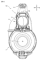
図8に、図7のII-II断面図を示す。 FIG. 8 shows a cross-sectional view taken along line II-II in FIG.

本体部10のモータケース部11には、ファンモータ40と、ファンモータ40の周りに第1の弾性部材60と第2の弾性部材70が収容されている。モータケース部11内には、ファンモータ40の上方に、掃除機本体1を制御する回路基板50が収容されている。 The motor case portion 11 of the main body portion 10 houses a fan motor 40 and a first elastic member 60 and a second elastic member 70 around the fan motor 40 . A circuit board 50 for controlling the cleaner body 1 is housed in the motor case portion 11 above the fan motor 40 .

ファンモータ40と回路基板50とは、上下方向に重なるように配置されている。このため、掃除機本体1の前後方向の寸法を短くできる。また、ファンモータ40は、モータケース部11がハンドル部12側と重畳して形成されることで、本体部10の前後方向(全長)の寸法を短くできる。 The fan motor 40 and the circuit board 50 are arranged to overlap in the vertical direction. Therefore, the longitudinal dimension of the cleaner body 1 can be shortened. Furthermore, since the fan motor 40 is formed so that the motor case portion 11 overlaps with the handle portion 12 side, the dimension of the main body portion 10 in the front-rear direction (total length) can be shortened.

また、ファンモータ40及び回路基板50は、ハンドル部12の第1把持部12a1の下方に位置している。これにより、使用者が第1把持部12a1を握って操作する場合、電気掃除機100の重心が第1把持部12a1の下方近傍になる。このため、電気掃除機100の先を上向きで使用する場合、電気掃除機100を安定して保持できる。 Further, the fan motor 40 and the circuit board 50 are located below the first grip portion 12a1 of the handle portion 12. Thereby, when the user grips and operates the first grip part 12a1, the center of gravity of the vacuum cleaner 100 is located near the bottom of the first grip part 12a1. Therefore, when using the vacuum cleaner 100 with the tip facing upward, the vacuum cleaner 100 can be stably held.

また、第1把持部12a1および第2把持部12a2とモータケース部11の上面板11dとの間には、手を挿入するための隙間12cが形成されている。 Furthermore, a gap 12c for inserting a hand is formed between the first gripping part 12a1 and the second gripping part 12a2 and the top plate 11d of the motor case part 11.

モータケース部11の上面板11dは、後方が下がる傾斜を有して形成されている。 The upper surface plate 11d of the motor case portion 11 is formed with an inclination such that the rear side is downwardly inclined.

回路基板50は、モータケース部11の上面板11dに沿ってまたは平行に近い傾斜をもって配置されている。これにより、手を挿入するための隙間12cを狭くすることなく、モータケース部11の内部の空間を広く活用できる。そのため、モータケース部11の上下寸法を短くでき、掃除機本体1の小型化を図れる。 The circuit board 50 is arranged along the upper surface plate 11d of the motor case portion 11 or with an inclination close to parallel to the upper surface plate 11d. Thereby, the space inside the motor case portion 11 can be widely utilized without narrowing the gap 12c for inserting the hand. Therefore, the vertical dimensions of the motor case portion 11 can be shortened, and the vacuum cleaner main body 1 can be made smaller.

蓄電池3は、ハンドル部12の第2把持部12a2の下方に配置されている。蓄電池3は、例えば、エネルギ効率の高いリチウムイオン電池で構成することができる。 The storage battery 3 is arranged below the second grip part 12a2 of the handle part 12. The storage battery 3 can be configured with, for example, a lithium ion battery with high energy efficiency.

ダストケース2内には、収容部2aの軸方向の後端にフィルタ5が収容されている。フィルタ5は、プリーツ状に折って構成されたものであり、フィルタ面積を大きくできるとともに、フィルタ5による圧力損失を低減することができる。フィルタ5は、例えば高密度のHEPAフィルタ(High Efficiency Particulate Air Filter)で構成されている。 A filter 5 is housed in the dust case 2 at the rear end of the housing portion 2a in the axial direction. The filter 5 is folded into a pleat shape, and the filter area can be increased, and the pressure loss caused by the filter 5 can be reduced. The filter 5 is composed of, for example, a high-density HEPA filter (High Efficiency Particulate Air Filter).

(第1実施形態)
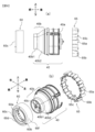
図9 (a)にファンモータ40、第1の弾性部材60および第2の弾性部材65の側面図、(b) にファンモータ40、第1の弾性部材60および第2の弾性部材65を左斜め上前方から見た斜視図を示す。
図9(a)、図9(b)に示すように、ファンモータ40は吸気孔40b1が前方に突出しその後方にテーパ状に広がるテーパ部40b2を有するケーシング40bと、これに内包されたインペラ40cと、このインペラ40cを駆動するモータ部40aにより構成されている。
(First embodiment)
FIG. 9(a) is a side view of the fan motor 40, the first elastic member 60, and the second elastic member 65, and FIG. 9(b) is a side view of the fan motor 40, the first elastic member 60, and the second elastic member 65. A perspective view seen diagonally from above and from the front is shown.
As shown in FIGS. 9(a) and 9(b), the fan motor 40 includes a casing 40b having an intake hole 40b1 protruding forward and a tapered portion 40b2 tapering toward the rear, and an impeller 40c contained in the casing 40b. and a motor section 40a that drives this impeller 40c.

図10(a)に第1の弾性部材60の正面図、(b) に第1の弾性部材60の背面図を示す。
図10(a)、図10(b)に示すように、第1の弾性部材60は円筒形状をしており、内側には環状の面で構成された円環部60aと、円周に沿うように放射状に複数個の突起部60bが等間隔に配置されている。各突起部60bは略15度の間隔で配置されている。なお、この間隔は略15度より大きい構成としても小さい構成としてもよい。突起部60bは後方にテーパ状に広がっている。この突起部60bが有するテーパ形状はケーシング40bのテーパ部40b2に沿うように構成されている。このように等間隔に突起部60bを備えることによって、モータ部40aをバランスよく保持することができ、防振効果を高めることができ、さらにモータが揺れることによる騒音も防ぐことができる。さらに、突起部60bを複数備えることによって、より強固にモータ部40aを安定してモータケース部11内に保持することができる。なお、突起部60bは図のように10以上の突起を有するものでも、それ以下のものでもよい。なお、図9および図10においては第1の弾性部材60は突起部60bとしているが、これに限られることなく、ケーシング40bのテーパ部40b2に沿う環状面で支持してもよい。
FIG. 10(a) shows a front view of the first elastic member 60, and FIG. 10(b) shows a rear view of the first elastic member 60.
As shown in FIGS. 10(a) and 10(b), the first elastic member 60 has a cylindrical shape, and has an annular portion 60a formed of an annular surface on the inside, and an annular portion 60a along the circumference. A plurality of protrusions 60b are arranged radially at equal intervals. Each protrusion 60b is arranged at intervals of approximately 15 degrees. Note that this interval may be larger or smaller than about 15 degrees. The protrusion 60b widens rearward in a tapered shape. The tapered shape of the protrusion 60b is configured to follow the tapered portion 40b2 of the casing 40b. By providing the protrusions 60b at equal intervals in this manner, the motor section 40a can be held in a well-balanced manner, the vibration-proofing effect can be enhanced, and noise caused by vibration of the motor can also be prevented. Furthermore, by providing a plurality of protrusions 60b, the motor section 40a can be more firmly and stably held within the motor case section 11. Note that the protrusion 60b may have 10 or more protrusions as shown in the figure, or may have fewer than 10 protrusions. Although the first elastic member 60 is shown as a projection 60b in FIGS. 9 and 10, the first elastic member 60 is not limited to this, and may be supported by an annular surface along the tapered portion 40b2 of the casing 40b.

第1の弾性部材60の円環部60aはケーシング40bの突出した吸気孔40b1の外周部に装着され、突起部60bは突出した吸気孔後方のテーパ部40b2に密着する。これにより、ファンモータ40と第1の弾性部材60の密着する面積が大きくなり、ファンモータ40の振動をより吸収することができ、ファンモータ40の振動低減が実現できる。
図11(a)に第2の弾性部材65の正面図、(b)に 第2の弾性部材65の背面図を示す。
図11 (a)、図11(b)に示すように、第2の弾性部材65は円筒形状をしており、外周に8個の円形部65aと2個の矩形部65bと12個の突起65cが配置されている。
8個の円形部65aは、第2の弾性部材65の円筒形状の円の中心に対して点対称の位置に配置されている。なお、円形部65aは図11のように10個以下の円形部を有するものでもよいし、それ以上でもよい。
2個の矩形部65bは、第2の弾性部材65の円筒形状の円の中心に対して点対称の位置に配置されている。なお、矩形部65aは図11のように5個以下の矩形部を有するものでもよいし、それ以上でもよい。
円形部65aと矩形部65bはモータケース部11に挟持されており、ファンモータ40の径方向の動きを抑制している。
The annular portion 60a of the first elastic member 60 is attached to the outer periphery of the protruding intake hole 40b1 of the casing 40b, and the protrusion 60b is in close contact with the tapered portion 40b2 at the rear of the protruding intake hole. This increases the area in which the fan motor 40 and the first elastic member 60 come into close contact with each other, making it possible to better absorb the vibrations of the fan motor 40 and thereby reducing the vibrations of the fan motor 40.
FIG. 11(a) shows a front view of the second elastic member 65, and FIG. 11(b) shows a rear view of the second elastic member 65.
As shown in FIGS. 11(a) and 11(b), the second elastic member 65 has a cylindrical shape, and has eight circular parts 65a, two rectangular parts 65b, and 12 protrusions on the outer periphery. 65c is placed.
The eight circular parts 65a are arranged at positions symmetrical with respect to the center of the cylindrical circle of the second elastic member 65. Note that the circular portion 65a may have 10 or less circular portions as shown in FIG. 11, or may have more than 10 circular portions.
The two rectangular portions 65b are arranged point-symmetrically with respect to the center of the cylindrical circle of the second elastic member 65. Note that the rectangular portion 65a may have five or less rectangular portions as shown in FIG. 11, or may have more than five rectangular portions.
The circular portion 65a and the rectangular portion 65b are sandwiched between the motor case portion 11 and suppress movement of the fan motor 40 in the radial direction.

12個の突起65cは円周上に等間隔に配置され、ファンモータ40の軸方向の動きを抑制することができ、ファンモータ40の振動低減、さらに騒音も防ぐことができる。なお、突起部65cは図11のように10個以上の円形部を有するものでもよいし、それ以下でもよい。
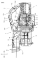
図13に図8のP部拡大した、モータケース30、第1の弾性部材60もしくは後述する第2実施形態の第3の弾性部材61と、第2の弾性部材65と、ファンモータ40の組状態の図を示し、図13にモータケース30の左斜め上後方から見た斜視図を示す。
The twelve protrusions 65c are arranged at equal intervals on the circumference, and can suppress the movement of the fan motor 40 in the axial direction, thereby reducing vibrations of the fan motor 40 and further preventing noise. Note that the protrusion 65c may have ten or more circular parts as shown in FIG. 11, or may have fewer than ten circular parts.
FIG. 13 shows a set of the motor case 30, the first elastic member 60 or the third elastic member 61 of the second embodiment described later, the second elastic member 65, and the fan motor 40, in an enlarged view of part P in FIG. FIG. 13 shows a perspective view of the motor case 30 as seen from the diagonally upper left rear side.

図12、図13に示すように、第1の弾性部材60の外周部60fはモータケース30の円形リブ30aによって挟持されており、ファンモータ40の径方向の動きを抑制している。また、第1の弾性部材60の前面部60cはモータケース30の仕切り板30bと圧接しており、ファンモータ40の軸方向の動きを抑制している。 As shown in FIGS. 12 and 13, the outer circumferential portion 60f of the first elastic member 60 is held between the circular ribs 30a of the motor case 30 to suppress movement of the fan motor 40 in the radial direction. Further, the front portion 60c of the first elastic member 60 is in pressure contact with the partition plate 30b of the motor case 30, and suppresses movement of the fan motor 40 in the axial direction.

また、第1の弾性部材60の前面部60cとモータケース30の仕切り板30bが圧接、第1の弾性部材60の前面裏部60dとケーシング40bの突出した吸気孔40b1前面部が圧接することで、モータケース30とファンモータ40間の気密を確保している。従って、当該部分に気密を確保するための追加部材を必要とせず、部品点数の削減及び軽量化を可能としている。 Further, the front part 60c of the first elastic member 60 and the partition plate 30b of the motor case 30 come into pressure contact, and the front back part 60d of the first elastic member 60 and the front part of the protruding intake hole 40b1 of the casing 40b come into pressure contact with each other. , ensuring airtightness between the motor case 30 and the fan motor 40. Therefore, there is no need for an additional member to ensure airtightness in the part, making it possible to reduce the number of parts and reduce the weight.

また、第1の弾性部材60の吸気孔側の穴部60eの径はファンモータ40の吸気孔側穴径より大きい構成としている。また、第1の弾性部材60の吸気孔側の前面部60cは前方から後方にかけて穴径が小さくなるような構成としている。これにより、ファンモータ40に流入する空気の流れを滑らかにし、吸気の損失の低減を実現している。
従って本実施例によれば、第1の弾性部材60がファンモータ40駆動時の衝撃を吸収しファンモータ40が本体100に触れることを防ぐことができ、本体への固定が確実になり品質が向上する。第1の弾性部材60を備えることで、主にファンモータ40に内包されるインペラ40cによる振動を低減することができる。さらに第2の弾性部材65を備えることで、主にモータ40aによる振動を低減することができる。なお、本実施例では第1の弾性部材60と第2の弾性部材65両方を備える構成を開示しているが、それに限られることはなく、いずれか一方で在っても振動を低減することはできるが、2つの弾性部材を両方備えることでより低振動・低騒音の電気掃除機を実現することができる。
Further, the diameter of the hole 60e on the intake hole side of the first elastic member 60 is larger than the diameter of the hole on the intake hole side of the fan motor 40. Further, the front surface portion 60c of the first elastic member 60 on the intake hole side is configured such that the hole diameter decreases from the front to the rear. This smoothes the flow of air flowing into the fan motor 40 and reduces loss of intake air.
Therefore, according to this embodiment, the first elastic member 60 can absorb the shock when the fan motor 40 is driven and can prevent the fan motor 40 from touching the main body 100, ensuring secure fixation to the main body and improving quality. improves. By providing the first elastic member 60, vibration mainly caused by the impeller 40c included in the fan motor 40 can be reduced. Furthermore, by providing the second elastic member 65, vibrations mainly caused by the motor 40a can be reduced. Note that although this embodiment discloses a configuration that includes both the first elastic member 60 and the second elastic member 65, the present invention is not limited to this, and vibrations can be reduced even if either one is present. However, by including both elastic members, a vacuum cleaner with lower vibration and noise can be realized.

(第2実施形態)
次に、前述した第1の弾性部材60の変形例について図12(a)、図12(b)を用いて説明する。なお、本実施例は第1の弾性部材60を第3の弾性部材61に変更するのみであって他の構成については同じ構成となっている。図12(a)は第3の弾性部材61の正面図を示し、(b)は 第2実施形態の第3の弾性部材61の背面図を示す。図12に示すように第3の弾性部材61は円筒形状をしており、内側には環状の面で構成された円環部61aと、円周に沿うように規則的に配置された複数個の突起部61bが配置されている。三角形状を保ちながら、規則的に突起部61bを備えることによって、ファンモータ40をバランスよく保持することができ、防振効果を高めることができる。さらに、モータが揺れることによる騒音も防ぐことができる。
図14にモーターケース30を示す。モーターケースは略円筒形状が内部に入り込んだ形をしており、内部に円形リブ30aと、仕切り板30bとを有する。
(Second embodiment)
Next, a modification of the first elastic member 60 described above will be described using FIGS. 12(a) and 12(b). In addition, in this embodiment, only the first elastic member 60 is changed to a third elastic member 61, and the other structures are the same. FIG. 12(a) shows a front view of the third elastic member 61, and FIG. 12(b) shows a rear view of the third elastic member 61 of the second embodiment. As shown in FIG. 12, the third elastic member 61 has a cylindrical shape, and has an annular portion 61a formed of an annular surface on the inside, and a plurality of elastic members regularly arranged along the circumference. A protrusion 61b is arranged. By regularly providing the protrusions 61b while maintaining the triangular shape, the fan motor 40 can be held in a well-balanced manner, and the vibration isolation effect can be enhanced. Furthermore, noise caused by vibration of the motor can also be prevented.
FIG. 14 shows the motor case 30. The motor case has a substantially cylindrical shape, and has a circular rib 30a and a partition plate 30b inside.

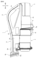
図15に、電気掃除機100を右側から視た側面図を示す。 FIG. 15 shows a side view of the vacuum cleaner 100 viewed from the right side.

ダストケース2の下部後端と掃除機本体1の下部前端には、ダストケース2を掃除機本体1に着脱するための着脱機構2g,19が設けられている。すなわち、ダストケース2を掃除機本体1に装着するときは、着脱機構2gと着脱機構19とが所定の機構により連結される。着脱機構2g,19は電気掃除機100の最下方に延出していて、特に、着脱機構19の下端が電気掃除機100の最下方となり、この着脱機構19の下には脚部19aが設けられている。また、蓄電池3の最後尾下端にも脚部3nが設けられている。 図17に示すように、電気掃除機100の下側を下として、水平な床面Yの上に載置したときは、ファンモータ40や蓄電池3のような重い部品が電気掃除機100の後方下部に存在することもあり、電気掃除機100は脚部19a,3nで水平な床面Y上に支持される。このとき、脚部19aが電気掃除機100の最下端に位置し、また、脚部19aは電気掃除機100の長手方向の中間位置に存在するため、水平な床面Yの上に載置した電気掃除機100は、図15に示すように、前方が斜め上側を向く。 Attachment and detachment mechanisms 2g and 19 for attaching and detaching the dust case 2 to and from the cleaner body 1 are provided at the lower rear end of the dust case 2 and at the lower front end of the cleaner body 1. That is, when attaching the dust case 2 to the cleaner body 1, the attachment/detachment mechanism 2g and the attachment/detachment mechanism 19 are connected by a predetermined mechanism. The attachment/detachment mechanism 2g, 19 extends to the lowest part of the vacuum cleaner 100, and in particular, the lower end of the attachment/detachment mechanism 19 is the lowest part of the vacuum cleaner 100, and the leg part 19a is provided below the attachment/detachment mechanism 19. ing. A leg portion 3n is also provided at the rearmost lower end of the storage battery 3. As shown in FIG. 17, when the vacuum cleaner 100 is placed with its lower side facing down on a horizontal floor surface Y, heavy components such as the fan motor 40 and the storage battery 3 are placed at the rear of the vacuum cleaner 100. The vacuum cleaner 100 may be located at the bottom, and the vacuum cleaner 100 is supported on the horizontal floor surface Y by the legs 19a and 3n. At this time, the leg part 19a is located at the lowest end of the vacuum cleaner 100, and since the leg part 19a is located at an intermediate position in the longitudinal direction of the vacuum cleaner 100, the vacuum cleaner 100 is placed on the horizontal floor surface Y. As shown in FIG. 15, the vacuum cleaner 100 has its front facing diagonally upward.

よって、吸引口となる接続口10aの先端部も斜め上側を向き、ハンディ清掃部材90の先端90sも斜め上側を向く。そのため、電気掃除機100は水平な床面Y上に支持された状態において、接続口10aやハンディ清掃部材90の内部に残っている塵埃が外部にこぼれ落ちにくい。 Therefore, the distal end of the connection port 10a serving as a suction port also faces diagonally upward, and the distal end 90s of the handy cleaning member 90 also faces diagonally upward. Therefore, when the vacuum cleaner 100 is supported on the horizontal floor surface Y, dust remaining inside the connection port 10a and the handy cleaning member 90 is unlikely to spill out to the outside.

図15に示すように蓄電池3への充電は掃除機本体1の右側部に設けられた端子tに図示しないACアダプタを接続することによって行うことができる。 As shown in FIG. 15, the storage battery 3 can be charged by connecting an AC adapter (not shown) to a terminal t provided on the right side of the cleaner body 1.

図16に、電気掃除機100に付属品の延長管300、標準吸口400が接続された状態の正面図を示す。 FIG. 16 shows a front view of the vacuum cleaner 100 with the accessory extension tube 300 and standard suction port 400 connected.

電気掃除機100は、掃除機本体1にハンディ清掃部材90が接続された状態で、延長管300を接続できるように構成されている。このように、掃除機本体1にハンディ清掃部材90を接続したままでも、延長管300を接続する接続口10a(図4参照)の位置は変わらない。よって、掃除機本体1と延長管300と標準吸口400とを接続した全長を短く抑えることができる。これにより、標準吸口400の位置が手元により近くなるので、電気掃除機100の取り回しが良好になり、使い勝手を向上できる。 The vacuum cleaner 100 is configured such that an extension tube 300 can be connected to the vacuum cleaner main body 1 with the handy cleaning member 90 connected thereto. In this way, even if the handy cleaning member 90 remains connected to the cleaner body 1, the position of the connection port 10a (see FIG. 4) for connecting the extension tube 300 does not change. Therefore, the total length of the connection between the cleaner body 1, the extension tube 300, and the standard suction port 400 can be kept short. This brings the standard suction port 400 closer to the user's hand, making it easier to handle the vacuum cleaner 100 and improving its usability.

電気掃除機100は、図16に示すスティック状態から、標準吸口400が接続された延長管300を取り外して、図2に示すハンディ状態にしたとしても、掃除機本体1にはハンディ清掃部材90が取り付けられたままである。よって、吸引力が高められた状態で掃除を行うことができる。 Even if the vacuum cleaner 100 is changed from the stick state shown in FIG. 16 to the handy state shown in FIG. It remains attached. Therefore, cleaning can be performed with increased suction power.

電気掃除機100について、延長管300及び標準吸口400を接続した使用方法以外に、例えば、接続口10aに標準吸口400を直接接続して、ハンディ状態の電気掃除機100として使用できる。 In addition to using the vacuum cleaner 100 by connecting the extension tube 300 and the standard suction port 400, for example, the vacuum cleaner 100 can be used as a handy vacuum cleaner 100 by directly connecting the standard suction port 400 to the connection port 10a.

このように、電気掃除機100では、掃除機本体1にハンディ清掃部材90を取り付けたままで、様々な付属品(アタッチメント)を着脱することができる。そのため、電気掃除機100は、掃除の使用形態を迅速に切り替えて掃除を行える。また、ハンディ清掃部材90は、掃除機本体1に取り付けたままにできるので、ハンディ清掃部材90を取り付けたハンディ状態の電気掃除機100において、塵埃を掻き出しながら掃除を行うことができる。また、ハンディ清掃部材90を取り外す必要がないので、無くすこともない。 In this way, in the vacuum cleaner 100, various accessories (attachments) can be attached and detached while the handy cleaning member 90 remains attached to the cleaner body 1. Therefore, the vacuum cleaner 100 can quickly switch the usage mode for cleaning. Moreover, since the handy cleaning member 90 can remain attached to the vacuum cleaner main body 1, cleaning can be performed while scraping out dust in the handy vacuum cleaner 100 with the handy cleaning member 90 attached. Furthermore, since there is no need to remove the handy cleaning member 90, there is no chance of it being lost.

図17に、電気掃除機100及び支持台70の側面図を示す。 FIG. 17 shows a side view of the vacuum cleaner 100 and the support stand 70.

電気掃除機100は、掃除機本体1に、延長管300と標準吸口400を接続したままの状態で支持台70に支持される。具体的には、延長管300の先端部に、先端を下側とした略L字形のフック301が設けられている。電気掃除機100を支持台70で支持するのに際して、フック301を支持台70のスタンド部72に設けられた係止部72aに係止させる。また、標準吸口400を載置面71a上の係止部71a1に係止させる。これにより、掃除機本体1側を上側にするとともに、標準吸口400側を下側として、電気掃除機100の全体を支持台70に支持させることができる。 The vacuum cleaner 100 is supported by the support stand 70 with the extension pipe 300 and the standard suction port 400 connected to the vacuum cleaner main body 1. Specifically, a substantially L-shaped hook 301 is provided at the distal end of the extension tube 300, with the distal end facing downward. When supporting the vacuum cleaner 100 on the support stand 70, the hook 301 is engaged with a locking part 72a provided on the stand part 72 of the support stand 70. Further, the standard suction port 400 is locked to the locking portion 71a1 on the mounting surface 71a. Thereby, the entire vacuum cleaner 100 can be supported on the support stand 70 with the vacuum cleaner main body 1 side on the upper side and the standard suction port 400 side on the lower side.

このように、電気掃除機100をスティック状態のままで支持台70に設置できるので、次に掃除をする際に、電気掃除機100を直ちにスティック状態のまま使用できる。 In this way, since the vacuum cleaner 100 can be installed on the support stand 70 in the stick state, the vacuum cleaner 100 can be used immediately in the stick state when cleaning next time.

図1に示すように、ベース部71の載置面71aは、延長管300よりも前方に延びて形成されている。これにより、延長管300に標準吸口400を接続した状態、つまり掃除機本体1に延長管300と標準吸口400を接続した状態(スティック状態)で、標準吸口400を載置面71aで支持できる。よって、電気掃除機100を支持台70に安定して支持させることができる。 As shown in FIG. 1, the mounting surface 71a of the base portion 71 is formed to extend further forward than the extension tube 300. Thereby, in a state where the standard suction port 400 is connected to the extension tube 300, that is, in a state where the extension tube 300 and the standard suction port 400 are connected to the vacuum cleaner main body 1 (stick state), the standard suction port 400 can be supported on the mounting surface 71a. Therefore, the vacuum cleaner 100 can be stably supported on the support stand 70.

図18に、スティック状態の電気掃除機100で床面Yを掃除するときの使用形態の側面図を示す。図16は、電気掃除機100に、ハンディ清掃部材90を装着したまま、延長管300及び標準吸口400を接続してスティック状態にして、電気掃除機100を使用者よりも前方に突き出して床面Yを掃除する場合である。 FIG. 18 shows a side view of a usage pattern when cleaning a floor surface Y with the vacuum cleaner 100 in a stick state. FIG. 16 shows a vacuum cleaner 100 with the handy cleaning member 90 attached, an extension pipe 300 and a standard suction port 400 connected to make it stick, and the vacuum cleaner 100 pushed out ahead of the user to clean the floor. This is a case of cleaning Y.

この場合、使用者は、ハンドル部12の第2把持部12a2を把持しながら、電気掃除機100を前後に移動させながら掃除を行うことができる。また、図示していないが、電気掃除機100を使用者の左右の脇に位置した状態で床面Yを掃除する場合には、使用者は、ハンドル部12の第1把持部12a1を把持しながら、電気掃除機100を前後に移動させることができる。このように、使用者が床面Yを掃除する場合には、ハンドル部12の位置を持ち替えて掃除できる。 In this case, the user can clean the vacuum cleaner 100 while holding the second grip part 12a2 of the handle part 12 and moving the vacuum cleaner 100 back and forth. Although not shown, when cleaning the floor surface Y with the vacuum cleaner 100 positioned on the left and right sides of the user, the user grasps the first grip portion 12a1 of the handle portion 12. At the same time, the vacuum cleaner 100 can be moved back and forth. In this manner, when the user cleans the floor surface Y, the user can change the position of the handle portion 12 and clean the floor surface Y.

従来のスティック状態にしたときに重心が先端側にある電気掃除機(特開2016-137165号公報参照)では、電気掃除機を床面Yより高い場所で掃除する場合、使用者が電気掃除機の先を上向きに持ち上げる必要があるので手首に負担が掛かり易くなる不都合があった。 In conventional vacuum cleaners whose center of gravity is on the tip side when in the stick state (see Japanese Patent Application Laid-open No. 2016-137165), when the vacuum cleaner is used in a place higher than the floor Y, the user can Since it is necessary to lift the tip upward, there is an inconvenience in that it tends to put strain on the wrist.

図18に、スティック状態の電気掃除機100で高い場所を掃除するときの使用形態図の側面図を示す。 FIG. 18 shows a side view of a usage pattern when cleaning a high place with the stick vacuum cleaner 100.

本電気掃除機100では、図18に示すように、重量物であるファンモータ40(図8参照)や蓄電池3がハンドル部12に近い位置(使用者の手元に近い位置)にあるので、電気掃除機100の重心が、使用者の手元に近くなる。 In this vacuum cleaner 100, as shown in FIG. 18, the fan motor 40 (see FIG. 8) and the storage battery 3, which are heavy items, are located close to the handle portion 12 (close to the user's hand), so the electric power is The center of gravity of the vacuum cleaner 100 is closer to the user's hand.

これにより、電気掃除機100をスティック状態にして、電気掃除機100を床面Yより高い場所、例えば階段Kを掃除する場合であっても掃除し易くなり、使い勝手を向上できる。 Thereby, even when the vacuum cleaner 100 is in a stick state and the vacuum cleaner 100 is used to clean a place higher than the floor surface Y, such as a staircase K, it becomes easier to clean, and usability can be improved.

なお、図19では、階段Kを掃除する場合を例に挙げて説明したが、電気掃除機100を持ち上げてエアコンの室内機のパネルなどを掃除する場合にも有効である。 In addition, in FIG. 19, the case of cleaning the stairs K was explained as an example, but it is also effective when lifting the vacuum cleaner 100 to clean the panel of an indoor unit of an air conditioner.

また、電気掃除機100をスティック状態で使用している場合において、階段Kの角(隅)に残った塵埃を取り除くときに、電気掃除機100から延長管300及び標準吸口400を取り外してハンディ状態にする。この場合、電気掃除機100にはハンディ清掃部材90が装着されたままであるので、そのまま直ちに階段Kの角(隅)に残った塵埃を取り除く掃除を行うことができ、塵埃の吸い残しを抑制できる。 In addition, when the vacuum cleaner 100 is used in a stick state, when removing dust remaining at the corner of the stairs K, the extension tube 300 and standard suction port 400 can be removed from the vacuum cleaner 100 to make it handy. Make it. In this case, since the handy cleaning member 90 remains attached to the vacuum cleaner 100, it is possible to immediately clean the corners of the stairs K to remove the dust remaining thereon, thereby suppressing the amount of dust left behind. .

なお、本発明は上記した実施例に限定されるものではなく、様々な変形例が含まれる。例えば、上記した実施例は本発明を分かりやすく説明するために詳細に説明したものであり、必ずしも説明した全ての構成を備えるものに限定されるものではない。 Note that the present invention is not limited to the above-described embodiments, and includes various modifications. For example, the embodiments described above are described in detail to explain the present invention in an easy-to-understand manner, and the present invention is not necessarily limited to having all the configurations described.

30 モータケース
30a モータケースの円形リブ
30b モータケースの仕切り板
40 ファンモータ
40a モータ
40b ケーシング
40b1 ケーシングの突出した吸気孔
40b2 ケーシングのテーパ部
60 第1の弾性部材
60a 第1の弾性部材の内側円環部
60b 第1の弾性部材の内側突起部
60c 第1の弾性部材の前面部
60d 第1の弾性部材の全面裏部
60e 第1の弾性部材の穴部
60f 第1の弾性部材の外周部
61 第3の弾性部材
61a 第3の弾性部材の内側円環部
61b 第3の弾性部材の内側突起部
65 第2の弾性部材
65a 第2の弾性部材の円形部
65b 第2の弾性部材の矩形部
65c 第2の弾性部材の突起
30 Motor case 30a Circular rib of motor case 30b Partition plate of motor case 40 Fan motor 40a Motor 40b Casing 40b1 Protruding intake hole of casing 40b2 Tapered part of casing 60 First elastic member 60a Inner ring of first elastic member Part 60b Inner protrusion of the first elastic member 60c Front part of the first elastic member 60d Full back part of the first elastic member 60e Hole part of the first elastic member 60f Outer peripheral part of the first elastic member 61 No. 3 elastic member 61a Inner ring part of the third elastic member 61b Inner protrusion part of the third elastic member 65 Second elastic member 65a Circular part of the second elastic member 65b Rectangular part of the second elastic member 65c Protrusion of second elastic member

Claims (1)

前方に突出した形状の吸気孔と、前記吸気孔の後方がテーパ状に広がるテーパ部を有するケーシングと、前記ケーシング内に配置されたインペラと、前記インペラを駆動するモータと、を備えたファンモータと、
記テーパ部の外周に装着され、前記テーパ部の形状に沿った突起を複数有する第1の弾性部材と、
前記第1の弾性部材より後方であって、前記ファンモータの外周に装着された環状の第2の弾性部材とを備え、
前記第2の弾性部材は、前記ファンモータの後部の外周部に対称に配置された突起と、前記突起と互い違いに設けられる円形部とをそれぞれ複数有し、
前記突起は、前記ファンモータの後部の外周部に当接するように内方に突出して形成され、
前記円形部は、前記第2の弾性部材の軸に沿う筒形状を有し、かつ外方に突出して形成され、前記ファンモータが収容されるモーターケース部に支持されていることを特徴とする電気掃除機。
A fan motor comprising: an intake hole having a shape that projects forward; a casing having a tapered portion that widens at the rear of the intake hole; an impeller disposed within the casing; and a motor that drives the impeller. and,
a first elastic member that is attached to the outer periphery of the tapered portion and has a plurality of protrusions that follow the shape of the tapered portion;
a second annular elastic member located behind the first elastic member and attached to the outer periphery of the fan motor;
The second elastic member each has a plurality of protrusions arranged symmetrically on the outer circumference of the rear part of the fan motor, and a plurality of circular parts provided alternately with the protrusions,
The protrusion is formed to protrude inward so as to come into contact with a rear outer peripheral portion of the fan motor,
The circular part has a cylindrical shape along the axis of the second elastic member, is formed to protrude outward, and is supported by a motor case part in which the fan motor is housed. Vacuum cleaner.
JP2020199282A 2020-12-01 2020-12-01 vacuum cleaner Active JP7376460B2 (en)

Priority Applications (1)

Application Number Priority Date Filing Date Title
JP2020199282A JP7376460B2 (en) 2020-12-01 2020-12-01 vacuum cleaner

Applications Claiming Priority (1)

Application Number Priority Date Filing Date Title
JP2020199282A JP7376460B2 (en) 2020-12-01 2020-12-01 vacuum cleaner

Publications (2)

Publication Number Publication Date
JP2022087375A JP2022087375A (en) 2022-06-13
JP7376460B2 true JP7376460B2 (en) 2023-11-08

Family

ID=81975663

Family Applications (1)

Application Number Title Priority Date Filing Date
JP2020199282A Active JP7376460B2 (en) 2020-12-01 2020-12-01 vacuum cleaner

Country Status (1)

Country Link
JP (1) JP7376460B2 (en)

Citations (6)

* Cited by examiner, † Cited by third party
Publication number Priority date Publication date Assignee Title
JP2002034200A (en) 2000-07-13 2002-01-31 Asmo Co Ltd Motor holding construction
US20140325789A1 (en) 2013-05-03 2014-11-06 Dyson Technology Limited Compressor flow path
JP2014219005A (en) 2013-05-03 2014-11-20 ダイソン テクノロジー リミテッド Vibration isolation mount
JP2017219143A (en) 2016-06-09 2017-12-14 Nok株式会社 Gear damper and process of manufacture thereof
JP2018034038A (en) 2017-12-07 2018-03-08 シャープ株式会社 Vacuum cleaner
JP2019037667A (en) 2017-08-28 2019-03-14 日立アプライアンス株式会社 Vacuum cleaner

Patent Citations (7)

* Cited by examiner, † Cited by third party
Publication number Priority date Publication date Assignee Title
JP2002034200A (en) 2000-07-13 2002-01-31 Asmo Co Ltd Motor holding construction
US20140325789A1 (en) 2013-05-03 2014-11-06 Dyson Technology Limited Compressor flow path
JP2014219005A (en) 2013-05-03 2014-11-20 ダイソン テクノロジー リミテッド Vibration isolation mount
JP2014217758A (en) 2013-05-03 2014-11-20 ダイソン テクノロジー リミテッド Compressor flow path
JP2017219143A (en) 2016-06-09 2017-12-14 Nok株式会社 Gear damper and process of manufacture thereof
JP2019037667A (en) 2017-08-28 2019-03-14 日立アプライアンス株式会社 Vacuum cleaner
JP2018034038A (en) 2017-12-07 2018-03-08 シャープ株式会社 Vacuum cleaner

Also Published As

Publication number Publication date
JP2022087375A (en) 2022-06-13

Similar Documents

Publication Publication Date Title
JP6488137B2 (en) Electric vacuum cleaner
JP5158380B2 (en) Handheld cleaning tool
US8028373B2 (en) Vacuum cleaners
US20070226947A1 (en) Vacuum cleaner with an integrated handheld vacuum cleaner unit
US20080105278A1 (en) Method for vacuum cleaning
TWI711421B (en) vacuum cleaner
EP2392244A2 (en) Hand-held and stick vacuum cleaner
JP6715569B2 (en) Vacuum cleaner
JP2008534116A (en) Multi function vacuum cleaner
TWI690294B (en) Electric vacuum cleaner
JP6710186B2 (en) Electric vacuum cleaner charging stand
CN115023167B (en) Vacuum cleaning appliance
JP2016136982A (en) Vacuum cleaner
JP7376460B2 (en) vacuum cleaner
JP2009504235A (en) Vacuum cleaner filter mounting structure
WO2020262600A1 (en) Electric vacuum cleaner
JP2020110507A (en) Vacuum cleaner
JP6918622B2 (en) Vacuum cleaner
JP2021019762A (en) Vacuum cleaner
JP7326186B2 (en) Vacuum cleaner suction body and vacuum cleaner provided with the same
CN115211752B (en) Hand-held dust collector
JP7174654B2 (en) vacuum cleaner
JP2022060812A (en) Vacuum cleaner
JP2020110509A (en) Vacuum cleaner
JP2021019761A (en) Vacuum cleaner

Legal Events

Date Code Title Description
A521 Request for written amendment filed

Free format text: JAPANESE INTERMEDIATE CODE: A523

Effective date: 20201204

RD02 Notification of acceptance of power of attorney

Free format text: JAPANESE INTERMEDIATE CODE: A7422

Effective date: 20220301

RD04 Notification of resignation of power of attorney

Free format text: JAPANESE INTERMEDIATE CODE: A7424

Effective date: 20220308

A621 Written request for application examination

Free format text: JAPANESE INTERMEDIATE CODE: A621

Effective date: 20220927

A977 Report on retrieval

Free format text: JAPANESE INTERMEDIATE CODE: A971007

Effective date: 20230414

A131 Notification of reasons for refusal

Free format text: JAPANESE INTERMEDIATE CODE: A131

Effective date: 20230418

A521 Request for written amendment filed

Free format text: JAPANESE INTERMEDIATE CODE: A523

Effective date: 20230619

TRDD Decision of grant or rejection written
A01 Written decision to grant a patent or to grant a registration (utility model)

Free format text: JAPANESE INTERMEDIATE CODE: A01

Effective date: 20231003

A61 First payment of annual fees (during grant procedure)

Free format text: JAPANESE INTERMEDIATE CODE: A61

Effective date: 20231026

R150 Certificate of patent or registration of utility model

Ref document number: 7376460

Country of ref document: JP

Free format text: JAPANESE INTERMEDIATE CODE: R150