JP7376207B2 - Rough terrain moving device and its control method - Google Patents
Rough terrain moving device and its control method Download PDFInfo
- Publication number
- JP7376207B2 JP7376207B2 JP2020218054A JP2020218054A JP7376207B2 JP 7376207 B2 JP7376207 B2 JP 7376207B2 JP 2020218054 A JP2020218054 A JP 2020218054A JP 2020218054 A JP2020218054 A JP 2020218054A JP 7376207 B2 JP7376207 B2 JP 7376207B2
- Authority
- JP
- Japan
- Prior art keywords
- ground
- chassis
- movable legs
- contact
- movable
- Prior art date
- Legal status (The legal status is an assumption and is not a legal conclusion. Google has not performed a legal analysis and makes no representation as to the accuracy of the status listed.)
- Active
Links
- 238000000034 method Methods 0.000 title claims description 43
- 230000033001 locomotion Effects 0.000 claims description 61
- 230000005484 gravity Effects 0.000 claims description 13
- 210000002414 leg Anatomy 0.000 description 305
- 230000008569 process Effects 0.000 description 9
- 238000010586 diagram Methods 0.000 description 8
- 230000036544 posture Effects 0.000 description 6
- 230000008859 change Effects 0.000 description 4
- NJPPVKZQTLUDBO-UHFFFAOYSA-N novaluron Chemical compound C1=C(Cl)C(OC(F)(F)C(OC(F)(F)F)F)=CC=C1NC(=O)NC(=O)C1=C(F)C=CC=C1F NJPPVKZQTLUDBO-UHFFFAOYSA-N 0.000 description 4
- 230000035939 shock Effects 0.000 description 4
- 239000011435 rock Substances 0.000 description 3
- 241000238631 Hexapoda Species 0.000 description 2
- 241001465754 Metazoa Species 0.000 description 2
- 238000004891 communication Methods 0.000 description 2
- 238000010276 construction Methods 0.000 description 2
- 238000005520 cutting process Methods 0.000 description 2
- 230000000694 effects Effects 0.000 description 2
- 238000005265 energy consumption Methods 0.000 description 2
- 239000012530 fluid Substances 0.000 description 2
- 210000000629 knee joint Anatomy 0.000 description 2
- 230000002093 peripheral effect Effects 0.000 description 2
- 230000001360 synchronised effect Effects 0.000 description 2
- 238000005452 bending Methods 0.000 description 1
- 230000005540 biological transmission Effects 0.000 description 1
- 230000003139 buffering effect Effects 0.000 description 1
- 230000007423 decrease Effects 0.000 description 1
- 238000001514 detection method Methods 0.000 description 1
- 238000005516 engineering process Methods 0.000 description 1
- 230000005284 excitation Effects 0.000 description 1
- 238000003384 imaging method Methods 0.000 description 1
- 238000004519 manufacturing process Methods 0.000 description 1
- 230000007246 mechanism Effects 0.000 description 1
- 230000010355 oscillation Effects 0.000 description 1
- 238000002360 preparation method Methods 0.000 description 1
- 230000009467 reduction Effects 0.000 description 1
- 239000004576 sand Substances 0.000 description 1
- 230000007704 transition Effects 0.000 description 1
Images


Description
本発明は、山林など、起伏の激しい場所で各種作業を行う際に使用する不整地移動装置とその制御方法に関する。 TECHNICAL FIELD The present invention relates to an uneven terrain moving device used when performing various types of work in places with severe ups and downs such as mountains and forests, and a method for controlling the same.
不整地での使用を前提とした建設機械や農業用機械などは、その移動手段として無限軌道を装備していることが多い。無限軌道は必然的に接地面積が増大するため、タイヤと比べて大きな摩擦を得られるほか、接地圧を軽減できるため、軟弱な地面でも沈み込みが抑制され、安定した移動を実現できる。ただし無限軌道についても、急傾斜地での移動には困難を伴うほか、大きな起伏を乗り越える際は、重心の移動によって姿勢が大きく変化し、作業員の安全が脅かされる恐れがある。さらに立木や岩などの障害物が途切れることなく連続する場合、無限軌道ではこれらを小刻みに回避しながら前進することも難しく、実際の作業では、立木の伐採や岩の除去などの整地作業を繰り返して奥地へ進むことになる。 Construction machinery and agricultural machinery intended for use on rough terrain are often equipped with endless tracks as a means of transportation. Since endless tracks inevitably have a larger ground contact area, they can obtain greater friction than tires, and can also reduce ground pressure, which prevents the vehicle from sinking even on soft ground, making it possible to achieve stable movement. However, even with endless tracks, it is difficult to move on steep slopes, and when overcoming large undulations, the center of gravity shifts, causing a significant change in attitude, which can threaten the safety of workers. Furthermore, when obstacles such as standing trees and rocks are continuous without interruption, it is difficult to move forward while avoiding them in small steps on a continuous track, and in actual work, land clearing work such as cutting down standing trees and removing rocks is repeated. We will proceed to the hinterland.
このように、無限軌道でも対応が難しい場所での移動手段については、人間や動物を模倣した脚構造が挙げられる。この場合、脚数を増やすことで安定性が向上するほか、個々の脚を自在に変形させることで地面の起伏を無理なく吸収でき、さらに障害物を避けることも容易である。そのため、以前から様々な多脚式の移動装置(多脚ロボット)が開発されており、その具体例として後記の特許文献が挙げられる。 In this way, leg structures that imitate humans and animals can be used as a means of transportation in places where even endless tracks are difficult to handle. In this case, increasing the number of legs improves stability, and by freely deforming each leg, it can easily absorb the unevenness of the ground, and it is also easier to avoid obstacles. Therefore, various multi-legged moving devices (multi-legged robots) have been developed for some time, and specific examples thereof include the patent documents mentioned below.
特許文献1では、不整地歩行型運搬機械の脚先接地機構が開示されており、接地時の緩衝作用を増大できるほか、接地の安定性を確実に判定できるといった特徴を有する。この機械は、架空に位置する基板フレームに複数の流体圧シリンダが設置された構造になっており、このシリンダのピストンロッドが脚として機能しており、ピストンロッドの下端部には、地面と接触する接地パッドが取り付けてある。加えてシリンダ内において、ピストンよりも上部の空間(上部空間部)は、パイプを介して全シリンダが連通している。そのためピストンのストロークの範囲内においては、全ての接地パッドに作用する押し下げ力が均等に揃うほか、複数の接地パッドのうち、一部だけが地面に接触した場合、その反力でピストンが一時的に押し上げられ、これによって押し出された流体がパイプを介して他のピストンに流入し、未だ地面に接触していていない接地パッドを強制的に押し下げることができる。そしてパイプ内に圧縮性を有する気体などを充填することで、緩衝作用を増大できるほか、接地パッドにセンサを取り付けることで、接地の安定性を確実に判定することができる。
次の特許文献2では、障害物回避性能に優れるほか、動物的で俊敏な運動特性を実現可能な多脚歩行ロボットが開示されている。この多脚歩行ロボットは、振り子のように揺動可能な脚部を機体の四隅などに配置したもので、機体には脚駆動部が組み込まれており、脚駆動部では電動モータの回転力を往復運動に変換しており、この往復運動がリンクを介して脚部に伝達される。そして個々の脚部は、垂直線を軸として旋回可能な状態で脚駆動部に取り付けてあり、しかも旋回モータによって脚部の旋回角度を調整することができる。その結果、脚部の旋回角度と蹴り出し方向との組み合わせにより、斜行や横行ができるようになり、さらに左右の脚部を逆方向にけり出すことで、移動を伴うことなくその場で旋回する「超信地旋回」もできるようになり、障害物回避性能に優れるほか、動物的で俊敏な運動特性を実現可能である。
The following
そして特許文献3では、多脚歩行ロボットの段差歩行制御装置が開示されている。このロボットは複数の脚部を備えており、個々の脚部は、膝関節を始めとして複数の屈曲可能な関節を有しており、個々の関節には電動モータが組み込まれており、この電動モータを制御装置で作動させている。加えてこのロボットには、撮像装置や距離画像センサーや姿勢センサーなどで構成される段差検知手段を備えており、実際に段差を検知した際は、その情報が制御装置に伝達され、膝関節の屈曲方向を変更するよう電動モータが制御され、脚部と段差との干渉を回避することができる。 Patent Document 3 discloses a step-step walking control device for a multi-legged walking robot. This robot is equipped with multiple legs, and each leg has multiple bendable joints, including a knee joint, and each joint is equipped with an electric motor. The motor is operated by a control device. In addition, this robot is equipped with a step detection means consisting of an imaging device, a distance image sensor, a posture sensor, etc. When a step is actually detected, that information is transmitted to the control device and the knee joint is adjusted. The electric motor is controlled to change the bending direction, and interference between the legs and the step can be avoided.
林業や治山事業などの現場では、立木や岩や崖など、様々な障害物が存在しており、これらを小刻みに回避しながら各種装置を移動させるには、前進の後に横行といった連続性のない動線を要求されることがある。このような連続性のない動線は、タイヤや無限軌道では実現不可能であるほか、多脚式の移動装置についても、その関節の配置によっては実現が難しい場合もある。したがって、あらゆる障害物を確実に回避できるよう、前進や横行や斜行といった全方位に制限なく移動可能な技術が待ち望まれている。 At sites such as forestry and forest conservation projects, there are various obstacles such as standing trees, rocks, cliffs, etc., and in order to move various equipment while avoiding these in small steps, it is necessary to move forward and then sideways. You may be asked for directions. Such discontinuous flow lines are not possible with tires or endless tracks, and may also be difficult to achieve with multi-legged transportation devices depending on the arrangement of their joints. Therefore, there is a need for technology that allows robots to move in all directions without restriction, such as forward, sideways, and diagonally, in order to reliably avoid all obstacles.
多脚式の移動装置は、タイヤや無限軌道と比べて複雑な動線にも対応しやすいが、これを林業や治山事業などで使用する場合、その過酷な環境から、人間のような二足歩行方式を導入することは難しい。また動物のような四足歩行方式についても、不整地で一本の脚を持ち上げた際、装置全体のバランスを維持できなくなる恐れがあり、安定性の確保に不安が残る。そこで脚数を増やすことが考えられるが、その場合、装置の製造費用の増大や制御ソフトの複雑化など、様々な課題がある。したがって極端な多脚化を避けた上、脚の制御方法を最適化することで、起伏の激しい過酷な環境においても、安定した移動を実現できることが望ましい。加えて、多脚式の移動装置は、脚だけで装置全体の荷重を受け止めるため、荷重条件が過酷になることが避けられず、その負荷をできるだけ軽減すべきである。 Multi-legged transportation devices are easier to handle complex movement lines than tires or tracks, but when used in forestry or forestry projects, due to the harsh environment, it is difficult to use two-legged transportation devices like humans. It is difficult to introduce a walking system. In addition, with regard to quadrupedal walking systems similar to those of animals, when one leg is lifted on uneven ground, there is a risk that the balance of the entire device may not be maintained, leaving concerns about ensuring stability. One idea would be to increase the number of legs, but in that case there would be various issues, such as an increase in the manufacturing cost of the device and the complexity of the control software. Therefore, it is desirable to avoid having an extremely large number of legs and to optimize the method of controlling the legs to achieve stable movement even in harsh environments with severe ups and downs. In addition, in a multi-legged moving device, since the legs alone bear the load of the entire device, the load conditions inevitably become severe, and the load should be reduced as much as possible.
本発明はこうした実情を基に開発されたもので、起伏の激しい過酷な環境においても安定した移動を実現可能で、しかも脚の負荷の軽減にも配慮された不整地移動装置とその制御方法の提供を目的としている。 The present invention was developed based on these actual circumstances, and is an all-terrain moving device and its control method that can achieve stable movement even in harsh environments with severe ups and downs, and also takes into consideration the reduction of the load on the legs. intended to provide.
前記の課題を解決するための請求項1記載の発明は、地面と対峙するように配置される車台と、該車台を架空に支持するための六組の可動脚と、該車台に載る車体と、からなり、前記車台の左右それぞれの側面には、三組の前記可動脚が前後方向に間隔を空けて配置してあり、個々の前記可動脚は、根元部と中間部と先端部の三要素が直列状に並んでおり、前記根元部は、前記車台の側面に配置してあり、且つ該車台に対して垂直軸を中心として揺動可能であり、前記中間部は、その一端側が前記根元部の端部に取り付けられ且つ該根元部に対して水平軸を中心として揺動可能であり、前記先端部は、前記中間部の両端部のうち前記根元部の反対側に取り付けられ且つ該中間部に対して水平軸を中心として揺動可能であり、該先端部において該中間部の反対側は地面と接触し、個々の前記可動脚は、他と連動することなく変形可能で、特定の前記先端部だけを地面から引き離すことが可能であり、さらに地面に接触している全ての該可動脚の前記根元部を同時に回転させることで前記車台を移動させることができ、前記可動脚が地面に接触し且つ前記車台が静止している初期状態において、前記根元部は、該車台の側面から遠ざかる方向に伸びており、また前記先端部は、該根元部の端部から見て下方且つ該車台から一段と遠ざかった位置で垂直方向に伸びており、残る前記中間部は、該先端部に向けて該車台から遠ざかるように斜め下方に伸びていることを特徴とする不整地移動装置である。
The invention as set forth in
本発明による不整地移動装置は、その土台となる車台と、この車台に架装される車体と、からなり、そのうち車台は、地面と対峙するように配置される平面状の部位で、真上から見て、不整地移動装置と同等の大きさであり、地面を移動するための機能が組み込まれる。また車体は、動力源や操作席などのほか、各種作業を行うための機器が搭載される。そして不整地移動装置の移動手段については、タイヤや無限軌道ではなく、六組の可動脚を用いるものとする。なお車台の外周面において、不整地移動装置の通常の前進方向と平行に揃う面を「側面」と称しており、当然ながらこの「側面」は、車台の中心を挟んで左右両側に配置される。さらに可動脚は、車台の個々の「側面」について、前後に間隔を空けて三組を配置してあり、昆虫類の脚と同様の構成になる。 The rough terrain moving device according to the present invention consists of a chassis serving as its base and a vehicle body mounted on the chassis. Viewed from above, it is the same size as an uneven terrain moving device, and has a built-in function for moving on the ground. In addition to the power source and operator's seat, the vehicle body is also equipped with equipment for performing various tasks. As for the means of movement of the rough terrain moving device, six sets of movable legs are used instead of tires or endless tracks. In addition, on the outer peripheral surface of the chassis, the surfaces that are aligned parallel to the normal forward direction of the rough terrain moving device are called "side surfaces", and naturally these "side surfaces" are arranged on both the left and right sides with the center of the chassis in between. . Furthermore, three sets of movable legs are arranged on each "side" of the chassis, spaced in front and back, similar to the legs of insects.
六組の可動脚は同一構成で、その配置だけが異なり、個々の可動脚は、根元部および中間部および先端部と称する棒状の三要素が関節を介して一体化したもので、そのうち根元部は車台に接続されており、また先端部の下側は地面と接触しており、残る中間部は根元部と先端部を結んでいる。そして根元部は、車台に対して揺動自在に取り付けられるが、この揺動軸は垂直方向に伸びており、その結果、根元部は水平面上を揺動することになる。さらに根元部の一端側は、車台の側面から突出しており、そこに中間部が接続される。したがって根元部を揺動させることで、車台を地面に対して移動させることができる。 The six sets of movable legs have the same configuration, differing only in their arrangement.Each movable leg is made up of three rod-shaped elements called the root, middle, and tip that are integrated through joints. is connected to the chassis, the lower side of the tip is in contact with the ground, and the remaining middle section connects the root and tip. The root portion is swingably attached to the vehicle chassis, but this swing axis extends in the vertical direction, and as a result, the root portion swings on a horizontal plane. Furthermore, one end side of the root portion protrudes from the side surface of the chassis, and the intermediate portion is connected thereto. Therefore, by swinging the base portion, the chassis can be moved relative to the ground.
先端部は、地面と接触する部位であり、概ね垂直方向に伸びており、その下部には地面との接触を考慮し、地面との摩擦を増大させる手段や、地面への沈み込みを防ぐ手段などを設ける。また中間部は、根元部と先端部を結ぶための部位であり、中間部の上端側は根元部と揺動自在に接続され、中間部の下端側は先端部と揺動自在に接続されるが、この中間部において、揺動の中心となる上下二箇所の軸は、いずれも水平方向に伸びるものとする。このように可動脚は、根元部と中間部と先端部を揺動可能な状態で一体化してあるため、中間部を立ち上げると、先端部が地面から引き離されることになる。 The tip is the part that comes into contact with the ground, and extends approximately vertically, and the lower part is equipped with means to increase friction with the ground and prevent it from sinking into the ground, taking into consideration contact with the ground. etc. will be established. The intermediate part is a part for connecting the root part and the tip part, and the upper end side of the intermediate part is swingably connected to the root part, and the lower end side of the intermediate part is swingably connected to the tip part. However, in this intermediate portion, the two axes at the top and bottom, which are the centers of rocking, both extend in the horizontal direction. In this way, the movable leg has the root, middle, and tip portions integrated in a swingable manner, so that when the middle portion is raised, the tip portion is pulled away from the ground.
可動脚が地面に接触している状態において、中間部は、根元部から先端部に向けて斜め下方に伸びているものとする。その結果、車台と地面との間隔を増大させることができ、地面の起伏が激しい場合でも、地面と車台との接触を避けやすくなる。加えて、先端部が車台の側面から過度に遠ざかることを回避でき、可動脚の関節部分に作用するモーメントを抑制できる。ただし可動脚は、地面の起伏に追従する必要があり、その結果、中間部の傾きも様々に変化し、水平方向に近づくこともあれば、垂直方向に近づくこともある。 When the movable leg is in contact with the ground, the intermediate portion extends diagonally downward from the base to the tip. As a result, it is possible to increase the distance between the vehicle undercarriage and the ground, making it easier to avoid contact between the ground and the undercarriage even when the ground is highly undulating. In addition, it is possible to prevent the tip end from moving too far away from the side surface of the chassis, and the moment acting on the joint portion of the movable leg can be suppressed. However, the movable legs need to follow the undulations of the ground, and as a result, the inclination of the middle part changes variously, sometimes approaching the horizontal direction and sometimes approaching the vertical direction.
可動脚を構成する根元部と中間部と先端部を自在に移動させるため、アクチュエータやモータなどの動力源が不可欠であるが、その具体的な配置方法などは、実情に応じて自在に決めて構わない。ただし本発明では、個々の可動脚を自在に変形させることを想定しており、リンクなどで複数の可動脚を連動させることはない。そのほか車台に載る車体の詳細についても、用途などに応じて自在に決めて構わないが、通常、車体には可動脚を駆動する動力源が搭載される。また車台と車体は、従来のショベルカーなどと同様、ターンテーブルを介して一体化することがある。 Power sources such as actuators and motors are essential in order to freely move the base, middle, and tip parts that make up the movable legs, but the specific arrangement of these can be determined freely depending on the actual situation. I do not care. However, in the present invention, it is assumed that each movable leg can be freely deformed, and a plurality of movable legs are not linked together using links or the like. In addition, the details of the vehicle body mounted on the chassis may be freely determined depending on the intended use, but the vehicle body is usually equipped with a power source that drives the movable legs. Additionally, the chassis and body may be integrated via a turntable, similar to conventional excavator cars.
このように、不整地移動装置を六組の可動脚で構成し、少なくとも三組の可動脚を地面に接触させることで、車台を安定した状態で静止させることができる。さらに四組以上の可動脚を地面に接触させることで、不整地においても、車台を安定した状態で静止させることができる。また個々の可動脚を根元部と中間部と先端部の三要素で構成し、そのうち中間部を斜方向に配置することで、車台と地面との間隔が増大し、安定した移動を実現できるほか、先端部が車台から過度に遠ざかることを回避でき、可動脚の関節部分に作用するモーメントが抑制され、可動脚の強度などに余裕が生じ、信頼性の向上に結び付く。 In this way, the rough terrain moving device is configured with six sets of movable legs, and by bringing at least three sets of movable legs into contact with the ground, the vehicle platform can be kept stationary in a stable state. Furthermore, by bringing four or more sets of movable legs into contact with the ground, the vehicle platform can remain stable even on uneven terrain. In addition, each movable leg is composed of three elements: a base, a middle part, and a tip, and by arranging the middle part diagonally, the distance between the chassis and the ground increases, making it possible to achieve stable movement. This prevents the tip from moving too far away from the vehicle chassis, suppresses the moment that acts on the joints of the movable legs, creates a margin for the strength of the movable legs, and improves reliability.
請求項2記載の発明は、可動脚と地面との接触部の構造に関するもので、個々の先端部には、地面に接触する接地体を設けてあり、接地体は先端部に対して自在に回転可能であり、且つ接地体には地面を突き固めるための加振部を組み込んであることを特徴とする。不整地移動装置を移動させる際は、可動脚の根元部を揺動させることになるが、その際、先端部と地面との接触点では、垂直軸を中心として先端部が回転するような動きを生じるため、双方の擦れ合いが避けられず、エネルギー消費が増大することになる。そこで本発明のように接地体を設けることが望ましい。
The invention according to
接地体は、先端部の最下部に組み込まれ、実際に地面と接触する部位だが、先端部と完全に一体化させる訳ではなく、先端部の長手方向に伸びる軸を中心として回転自在とする。その結果、根元部の揺動による影響が吸収され、地面との擦れ合いが解消される。なお接地体は、地面との接地圧を軽減するため、球状や平面状など、水平方向に面積を増大させた形状とする。さらに接地体の内部には、加振部を組み込む。 The grounding body is built into the lowest part of the tip and is the part that actually comes into contact with the ground, but it is not completely integrated with the tip and is rotatable around an axis that extends in the longitudinal direction of the tip. As a result, the influence of the rocking of the base is absorbed, and friction with the ground is eliminated. Note that the grounding body has a shape with an increased area in the horizontal direction, such as a spherical shape or a flat shape, in order to reduce the ground contact pressure with the ground. Furthermore, a vibrating section is incorporated inside the grounding body.
加振部は、接地後の可動脚の安定性を確保するため、接地体を激しく振動させる機能を有しており、これを利用して接地後の地面の状態を把握できるほか、地面に振動や衝撃を与えてクレーター状に陥没させ、必要な支持力を確保することができる。接地体が地面に接触した際、その場所に落ち葉やガレキなどが堆積しているならば、支持力が極端に不足し、可動脚は本来の機能を発揮できない。そのため、接地体をより深く下降させるか、あるいは接地体を地面から引き離して別の場所に移動させるなど、何らかの判断を行う必要がある。この判断を行うため、接地体が地面に接触した直後、加振部を作動させて接地体に振動や衝撃を与え、これによる反力の推移を計測する。そして時間の経過によって反力が増大したならば、この場所で支持力を確保できると判断し、接地体をさらに下降させていく。逆に反力が増大しない場合、「空洞」や「底なし沼」のような状態と判断し、接地場所を変更することになる。 The vibrating section has the function of violently vibrating the grounding body in order to ensure the stability of the movable legs after touching the ground.Using this, it is possible to grasp the state of the ground after touching down, and also to generate vibrations on the ground. It is possible to create a crater-like structure by applying an impact to the structure, thereby securing the necessary supporting force. When the grounding body makes contact with the ground, if fallen leaves, debris, etc. have accumulated there, the supporting force will be extremely insufficient and the movable legs will not be able to perform their original function. Therefore, it is necessary to make some kind of decision, such as lowering the grounding object deeper, or pulling the grounding object off the ground and moving it to another location. In order to make this determination, immediately after the grounding object contacts the ground, the vibrating section is activated to apply vibrations and shocks to the grounding object, and the transition of the resulting reaction force is measured. If the reaction force increases over time, it is determined that supporting force can be secured at this location, and the grounding body is lowered further. On the other hand, if the reaction force does not increase, it is determined that the ground is in a ``hollow'' or ``bottomless swamp'' state, and the grounding location is changed.
請求項3記載の発明は、不整地移動装置を前後方向に移動させるための制御方法であって、車台と対峙する地面において、不整地移動装置の重心位置の外側には、車台の左前方および右前方および左後方および右後方の四箇所からなる安定支持領域を想定し、個々の安定支持領域には、一組以上の可動脚が接触している状態を維持する安定移動方法と、安定支持領域に依存することなく、車台の左側または右側のいずれか一方は、その中央に位置する可動脚だけが地面に接触している状態を許容する高速移動方法と、の二つの移動方法を切り替え可能としたことを特徴としている。 The invention as set forth in claim 3 is a control method for moving an off-road moving device in the front-rear direction, wherein on the ground facing the undercarriage, outside the center of gravity of the off-road moving device, there is a left front of the undercarriage and a Assuming a stable support area consisting of four locations: right front, left rear, and right rear, each stable support area has a stable movement method that maintains one or more pairs of movable legs in contact with each other, and a stable support area. Regardless of the area, it is possible to switch between two movement methods: a high-speed movement method that allows only the movable legs located in the center to be in contact with the ground on either the left or right side of the chassis. It is characterized by the following.
この不整地移動装置の前進方法は様々だが、起伏の激しい場所では、可動脚が六組であることを有効活用し、安定した前進を行うことが望ましい。しかし通常の路面などでは、必然的に安定性が確保されるため、利便性を考慮し、高速で移動できることが望ましい。そこで請求項3記載の発明では、「安定移動方法」と「高速移動方法」を自在に切り替え可能として、安定性と利便性を両立させている。なお「安定移動方法」では、車台直下の地面において、不整地移動装置の重心位置を基準として、車台の左前方および右前方および左後方および右後方の四箇所からなる「安定支持領域」を想定する。そして個々の「安定支持領域」には、常時、少なくとも一組の可動脚を接触させている。対して「高速移動方法」では、「安定支持領域」を考慮することなく、車台の左右いずれか一方を中央の可動脚だけで支持することがある。 There are various ways to move forward with this rough terrain moving device, but in places with severe ups and downs, it is desirable to make effective use of the six sets of movable legs to achieve stable forward movement. However, on normal road surfaces, stability is inevitably ensured, so it is desirable to be able to move at high speeds for convenience. Therefore, in the invention described in claim 3, it is possible to freely switch between the "stable movement method" and the "high speed movement method" to achieve both stability and convenience. In addition, the "stable movement method" assumes a "stable support area" consisting of four locations on the ground directly under the chassis, at the front left, front right, rear left, and rear right of the chassis, based on the center of gravity of the rough terrain moving device. do. At least one set of movable legs is always in contact with each "stable support area." On the other hand, in the ``high-speed movement method,'' either the left or right side of the chassis may be supported by only the central movable legs without considering the ``stable support area.''
この「安定移動方法」の初期段階では、全ての可動脚が車台の真横に突出している状態を想定しており、その後、中央に位置する二組の可動脚の先端部を地面から引き離し、次にこの二組の可動脚を前方に移動させた後、その先端部を「安定支持領域」に接触させる。その結果、中央に位置する二組の可動脚と、後方に位置する二組の可動脚の計四組で装置全体を支持できるようになり、前方に位置する二組の可動脚を地面から引き離すことができる。 In the initial stage of this "stable movement method", it is assumed that all movable legs protrude directly to the side of the vehicle chassis, and then the tips of the two sets of movable legs located in the center are pulled away from the ground, and then After moving these two sets of movable legs forward, their tips are brought into contact with the "stable support area." As a result, the entire device can be supported by a total of four sets, two sets of movable legs located in the center and two sets of movable legs located at the rear, and the two sets of movable legs located at the front can be pulled off the ground. be able to.
次に、前方に位置する二組の可動脚を地面から引き離し、次にこの二組の可動脚を前方に移動させるため、これらの根元部を回転させた後、その先端部を地面に接触させる。以降、六組の可動脚が地面と接触した状態になり、ここで全ての可動脚の根元部を同時に回転させると、可動脚によって車台が押し出され、不整地移動装置が前進することになる。この際、回転の速度は、全ての可動脚で同期させることになるが、車台の左側と右側では、回転の方向が反転する。なお前進時に生じる地面との擦れ合いを防ぐため、根元部の回転と併せ、可動脚の各関節を個別に変形させる。そして根元部の回転を終えると、車台の前方および中央に位置する四組の可動脚については、その根元部が車台の真横に突出した状態になるが、後方に位置する二組の可動脚については、車台の後方に突出した状態になる。 Next, the two sets of movable legs located in front are pulled away from the ground, and in order to move these two sets of movable legs forward, their bases are rotated and their tips are brought into contact with the ground. . Thereafter, the six sets of movable legs are in contact with the ground, and when the bases of all the movable legs are rotated at the same time, the vehicle platform is pushed out by the movable legs, and the rough terrain moving device moves forward. At this time, the speed of rotation will be synchronized on all movable legs, but the direction of rotation will be reversed on the left and right sides of the chassis. In addition to rotating the base, each joint of the movable legs is deformed individually to prevent friction with the ground that occurs when moving forward. When the bases have finished rotating, the bases of the four sets of movable legs located at the front and center of the chassis will protrude directly to the sides of the chassis, but for the two sets of movable legs located at the rear, protrudes to the rear of the chassis.
その後、中央に位置する二組の可動脚を地面から引き離して車台の後方に移動させ、その先端部を「安定支持領域」に接触させる。この段階では、前方に位置する二組の可動脚と、中央に位置する二組の可動脚の計四組で装置全体を支持できる。したがって、後方に位置する二組の可動脚を地面から引き離すことができ、これらの根元部を車台の真横に突出した状態に戻すことができる。以降、前後四組の可動脚で車台を支持できるため、中央に位置する二組の可動脚は自在に移動させることができ、この段階で車台を前進させるための一サイクルが終了する。そして、この一連のサイクルを留まることなく連続して繰り返すことで、車台を円滑に前方に移動させることができ、当然ながら同様の方法で車台を後退させることもできる。このように、中央に位置する二組の可動脚を前方または後方に移動させる際、その先端部を「安定支持領域」に接触させることで、常に車台の四隅が地面で支持された状態になり、途切れることなく安定性を確保することができる。 Then, the two sets of movable legs located in the center are pulled off the ground and moved to the rear of the chassis, bringing their tips into contact with the "stable support area." At this stage, the entire device can be supported by a total of four sets: two sets of movable legs located at the front and two sets of movable legs located at the center. Therefore, the two sets of movable legs located at the rear can be pulled away from the ground, and their base portions can be returned to a state protruding directly to the side of the vehicle chassis. From then on, the chassis can be supported by the four sets of front and rear movable legs, so the two sets of movable legs located in the center can be moved freely, and one cycle for moving the chassis forward is completed at this stage. By repeating this series of cycles continuously without stopping, the vehicle platform can be smoothly moved forward, and of course, the vehicle platform can also be moved backward in the same manner. In this way, when moving the two sets of movable legs located in the center forward or backward, by having their tips contact the "stable support area," the four corners of the chassis are always supported by the ground. , it is possible to ensure stability without interruption.
対して「高速移動方法」では、個々の可動脚を移動させる際、「安定支持領域」を考慮することがない。そのため、車台の左側または右側のいずれか一方は、その中央に位置する可動脚だけを地面に接触させ、三組の可動脚だけで装置全体を支持する状態が許容される。その結果、移動のための一サイクルが簡素化され、「安定移動方法」では不可能な高速移動が実現する。そして請求項3記載の発明では、必要に応じて「安定移動方法」と「高速移動方法」を切り替えることができる。 On the other hand, in the "high-speed movement method", the "stable support area" is not considered when moving each movable leg. Therefore, on either the left side or the right side of the vehicle platform, only the movable leg located in the center is brought into contact with the ground, allowing the entire device to be supported by only three sets of movable legs. As a result, one cycle for movement is simplified, and high-speed movement that is impossible with the "stable movement method" is realized. In the third aspect of the invention, it is possible to switch between the "stable movement method" and the "high speed movement method" as necessary.
請求項4記載の発明は、不整地移動装置を任意の方向に移動させるための制御方法であって、車台と対峙する地面において、不整地移動装置の重心位置の外側には、車台の左前方および右前方および左後方および右後方の四箇所からなる安定支持領域を想定し、個々の安定支持領域には、一組以上の可動脚が接触している状態を維持しながら個々の可動脚を変形させていき、少なくとも車台の四隅に位置する四組の可動脚を地面に接触させ、その後、個々の安定支持領域には、一組以上の可動脚が接触している状態を維持しながら、地面に接触している可動脚の根元部と中間部の両方または中間部だけを変形させ、車台を移動させることを特徴とする。 The invention according to claim 4 is a control method for moving an off-road moving device in an arbitrary direction, wherein on the ground facing the vehicle platform, there is a left front portion of the off-road moving device outside the center of gravity of the off-road moving device. Assuming a stable support area consisting of four locations, front right, rear left, and rear right, each stable support area has one or more pairs of movable legs that maintain contact with each other. The vehicle is deformed, and at least four sets of movable legs located at the four corners of the chassis are brought into contact with the ground, and thereafter, while maintaining a state in which one or more sets of movable legs are in contact with each stable support area, The vehicle platform is characterized by deforming both the root part and the intermediate part or only the intermediate part of the movable legs that are in contact with the ground to move the vehicle platform.
この不整地移動装置は、前後方向の移動のほか、前後方向に移動を伴うことなく純粋に横行させることができ、さらに前後方向の移動と横行を同期させることで斜行も可能である。したがって、車台をあらゆる方向に移動させることができる。なお純粋に横行させる場合、まずは個々の可動脚が車台の真横に突出する状態としておき、次に車台の一側面に並ぶ三組の可動脚の先端部を順次地面から引き離し、車台から遠方の地面に接触させる。その後、この三組の可動脚の中間部を直立させ、さらにこれと同時に、車台の反対側に並ぶ三組の可動脚の中間部を横倒しにすると、車台は横方向に移動(横行)することになる。このように車台を横方向に移動させる際は、可動脚の根元部を回転させる必要がなく、全ての根元部は車台の真横に突出した状態を維持する。そのため横行の際、車台が前後方向に移動することはない。 In addition to moving in the front-back direction, this rough terrain moving device can also move purely horizontally without any movement in the front-back direction, and can also move diagonally by synchronizing the movement in the front-back direction and the horizontal movement. Therefore, the chassis can be moved in any direction. In addition, in the case of purely traversing, first let the individual movable legs protrude directly to the side of the chassis, then pull the tips of the three sets of movable legs lined up on one side of the chassis away from the ground one by one, and move the legs far away from the chassis. contact with. Then, if the middle parts of these three sets of movable legs are made to stand upright, and at the same time, the middle parts of the three sets of movable legs lined up on the opposite side of the chassis are laid down, the chassis will move laterally (traverse). become. When the vehicle chassis is moved laterally in this manner, there is no need to rotate the base portions of the movable legs, and all base portions maintain a state of protruding directly to the side of the vehicle chassis. Therefore, when the vehicle is traversing, the chassis does not move forward or backward.
このような横行に先立ち、個々の可動脚の先端部を車台から遠方の地面に接触させる際は、その先端部が一時的に地面から離れるため、車台の安定性が低下する。特に車台の四隅に位置する可動脚が地面から離れると、車台が不安定になり、姿勢が大きく変化する恐れがある。そこで請求項4記載の発明においても、車台と対峙する地面に四箇所の「安定支持領域」を想定し、個々の「安定支持領域」には、一組以上の可動脚が常時接触しているものとする。つまり四隅に位置する可動脚のいずれかを地面から引き離す際は、あらかじめその前後に隣接する可動脚を近づけておき、地面から離れた可動脚の代替として機能させる。 Prior to such traversal, when the tips of the individual movable legs are brought into contact with the ground far from the vehicle chassis, the tips are temporarily separated from the ground, reducing the stability of the vehicle chassis. In particular, if the movable legs located at the four corners of the chassis leave the ground, the chassis may become unstable and its posture may change significantly. Therefore, in the invention according to claim 4, four "stable support areas" are assumed on the ground facing the vehicle platform, and one or more sets of movable legs are in constant contact with each "stable support area". shall be taken as a thing. In other words, when one of the movable legs located at the four corners is to be pulled away from the ground, the movable legs adjacent to it in front and behind it are brought closer in advance to function as a substitute for the movable leg that is separated from the ground.
さらに車台を横行させる際、併せて可動脚の根元部を回転させることで、車台を斜行させることができる。当然ながら、根元部の回転方向を調整することで、斜め後方に移動させることもできる。このように本発明による不整地移動装置は、可動脚の構造上、前進または後退に横行を組み合わせることができるため、車台を前後左右のあらゆる方向に移動させることができる。なお横行や斜行の際は、六組の可動脚の全てが地面に接触している場合もあるが、車台の中央に配置された二組の可動脚の一方または両方は、地面から離れている場合もあり得る。そのほか横行や斜行のため、根元部や中間部を変形させる際は、地面と擦れ合いを防ぐため、先端部の姿勢も調整する必要がある。 Furthermore, when the vehicle platform is moved sideways, the base portions of the movable legs are also rotated, thereby making it possible to cause the vehicle platform to move diagonally. Of course, by adjusting the direction of rotation of the base, it can also be moved diagonally backward. As described above, the rough terrain moving device according to the present invention can combine forward movement or backward movement with traverse movement due to the structure of the movable legs, so that the vehicle platform can be moved in all directions, forward, backward, leftward, and rightward. When traveling sideways or diagonally, all six sets of movable legs may be in contact with the ground, but one or both of the two sets of movable legs placed in the center of the chassis may be off the ground. There may be cases where there are. In addition, because it moves horizontally or diagonally, when deforming the base or middle part, it is necessary to adjust the attitude of the tip part to prevent it from rubbing against the ground.
請求項1記載の発明のように、不整地移動装置を六組の可動脚で構成し、少なくとも三組の可動脚を地面に接触させることで、車台を安定した状態で静止させることができる。さらに四組以上の可動脚を地面に接触させることで、不整地においても、車台を安定した状態で静止させることができる。また個々の可動脚を根元部と中間部と先端部の三要素で構成し、そのうち中間部を斜方向に配置することで、車台と地面との間隔が増大し、安定した移動を実現できるほか、先端部が車台から過度に遠ざかることを回避でき、可動脚の関節部分に作用するモーメントが抑制され、可動脚の強度などに余裕が生じ、信頼性の向上に結び付く。
According to the invention described in
請求項2記載の発明のように、可動脚の先端部に接地体を設けることで、地面との接地圧を軽減でき、自重による沈み込みなどを防ぐことができる。しかも接地体は、先端部に対して回転自在とすることで、車台を移動させるため根元部を回転させる際、地面との擦れ合いが解消され、車台の円滑な移動が実現する。そのほか接地体には、地面に振動や衝撃を与える加振部を組み込むことで、接地後の地面の状態を把握できるほか、地面をクレーター状に陥没させ、支持力を確保することができる。 By providing the grounding body at the tip of the movable leg as in the second aspect of the invention, the grounding pressure with the ground can be reduced, and sinking due to its own weight can be prevented. In addition, by making the grounding body rotatable relative to the tip, when the base is rotated to move the chassis, there is no friction with the ground, and smooth movement of the chassis is achieved. In addition, the grounding body incorporates an excitation unit that applies vibrations and shocks to the ground, allowing it to grasp the state of the ground after touching down, as well as creating a crater-like depression in the ground to ensure support.
請求項3記載の発明のように、個々の安定支持領域には一組以上の可動脚が常時接触している安定移動方法と、車台の左側または右側のいずれか一方は、その中央に位置する可動脚だけが地面に接触している状態を許容する高速移動方法と、の二つの移動方法を切り替え可能とすることで、道路などでの高速移動と、不整地での安定した移動を無理なく両立させることができ、利便性が向上する。 The invention according to claim 3 provides a stable movement method in which one or more sets of movable legs are always in contact with each stable support area, and either the left side or the right side of the chassis is located in the center thereof. By making it possible to switch between two modes of movement: a high-speed movement method that allows only the movable legs to be in contact with the ground, it is possible to move at high speeds on roads and move stably on uneven terrain. It is possible to achieve both, improving convenience.
請求項4記載の発明のように、地面に接触している可動脚の中間部だけを変形させることで、前後方向の移動を伴うことなく車台を純粋に横行させることができ、さらに地面に接触している可動脚の根元部と中間部を同時に変形させることで、車台を斜行させることもできる。その結果、車台を前後左右のあらゆる方向に移動させることが可能になり、様々な制約を生じる不整地においても、障害を回避して移動を継続することができる。しかも可動脚の接地位置を変更する際は、車台の四隅に安定支持領域を想定し、個々の安定支持領域には常時一組以上の可動脚が接触している状態を維持することで、車台の支持が不安定になることがなく、起伏の激しい場所においても、安定した全方位移動が実現する。 According to the fourth aspect of the invention, by deforming only the middle part of the movable leg that is in contact with the ground, the vehicle platform can be moved purely horizontally without moving forward or backward, and furthermore, the movable leg can be moved horizontally without moving forward or backward. By simultaneously deforming the base and middle portions of the movable legs, the chassis can be moved diagonally. As a result, the vehicle platform can be moved in all directions, forward, backward, left, and right, and can continue to move while avoiding obstacles even on rough terrain that poses various restrictions. Moreover, when changing the ground contact position of the movable legs, stable support areas are assumed at the four corners of the vehicle chassis, and one or more pairs of movable legs are always in contact with each stable support area. The support will not become unstable, and stable omnidirectional movement will be achieved even in areas with severe ups and downs.
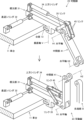
図1は、本発明による不整地移動装置の形状例を示しており、車台11と車体61を分離した状態で描いてある。ここでの車台11は、地面と対峙する平面状であり、その上部に車体61が架装されるが、車台11に対して車体61が自在に回転できるよう、双方の間にはターンテーブル15を介在させている。なおターンテーブル15は、車台11の中心に配置してある。また車台11は、車体61を安定して支持できるよう、真上から見て車体61とほぼ同等の大きさとしてある。そして車体61の前方には操作席62を設けてあるほか、その後方には動力源となるエンジンを搭載しており、さらに操作席62の隣からはアーム64が伸びており、その先端にはハーベスタ65を取り付けてある。アーム64は、従来の建設機械と同様、所定の範囲で揺動可能であり、その先のハーベスタ65は、伐採された木の枝を打ち払い、所定の長さに切り出す機能を有する。当然ながらアーム64やハーベスタ65は、本発明による不整地移動装置の一例に過ぎず、車体61の具体的な構成は自在である。
FIG. 1 shows an example of the shape of the rough terrain moving device according to the present invention, and is depicted with the
車台11は長方形状で、その四箇所の外周面のうち、図の左下に位置する狭い面が不整地移動装置の前方側になり、その反対の右上に位置する面が後方側になる。そして車台11の側面(車台11の外周面のうち、広い面)には、左右いずれも三組の可動脚(21乃至26)が所定の間隔を空けて並んでおり、しかも車台11を挟んで隣接する左右の可動脚(21と22、23と24、25と26)は、車台11の幅方向において段差なく並んでおり、昆虫類の脚と同様の配置になっている。また六組の可動脚(21乃至26)は同一構成で、いずれも根元部31と中間部41と先端部51の三要素を揺動自在に一体化してあり、しかも根元部31や中間部41や先端部51は、個別に移動させることができる。
The
根元部31は、車台11の側面から突出する台座13に取り付けられ、台座13を貫く垂直軸Vを中心として自在に揺動可能である。したがって根元部31は、垂直軸Vを中心として水平面に沿って揺動することになるが、その範囲は150度程度になる。当然ながら台座13は、可動脚(21乃至26)に応じて六箇所に配置してある。そして根元部31の両端部のうち、車台11から突出する側には、中間部41の上端部が取り付けられるが、双方は水平軸H1を中心として揺動自在に一体化される。そのため中間部41は、根元部31の下方に突出することも可能だが、その逆で上方に突出することも可能である。
The
先端部51は、中間部41の下端部に接続され、実際に地面と接触する役割を担い、車台11と地面との間隔を確保するため、概ね直立した状態で使用される。そして中間部41と先端部51は、水平軸H2を中心として揺動自在に一体化される。このように可動脚(21乃至26)は、垂直軸Vのほか、根元部31側の水平軸H1と先端部51側の水平軸H2により、複数の関節を有する構造になっており、これらを利用して個々の可動脚(21乃至26)の形状を様々に変化させ、車台11の移動を実現している。
The
可動脚(21乃至26)の先端部51の下方には、地面と接触することを考慮し、球形の接地体58を設けてある。接地体58は、自重によって地面に食い込むことで反力が増大し、車台11の安定性を確保することができ、さらに地面との密着性を高めるため、その表面には微細な凹凸を形成してある。なお接地体58は、先端部51と一体化している訳ではなく、先端部51の長手方向を軸として回転可能としてある。その結果、根元部31が車台11に対して揺動した際、その反力の増大を防いでいる。そのほか、接地体58に隣接して加振部57を組み込んである。加振部57は、文字通り接地体58に振動や衝撃を与えるもので、接地体58が地面に接触した際に作動させ、その後の挙動から地面の状態を把握できるほか、仮に地面の支持力が小さい場合でも、振動や衝撃を与えてクレーター状に陥没させることで、支持力を確保することができる。
A
そのほか、過酷な環境下で作業者が操作席62に座っていると、転倒や接触など、様々な危険に巻き込まれる恐れがある。そこで、遠隔操作を実現するコントローラ68を用い、作業者は不整地移動装置から離れ、安全な場所から指令を送ることもできる。なお、不整地移動装置とコントローラ68との間の情報伝達は、電波などの無線通信を利用することが多いが、障害物が林立する場所などでは有線通信を利用することもある。 In addition, if a worker is sitting on the operator seat 62 in a harsh environment, there is a risk that the worker may fall over or come into contact with the operator, and be involved in various dangers. Therefore, by using the controller 68 that realizes remote control, the operator can leave the rough terrain moving device and send commands from a safe location. Note that information transmission between the rough terrain moving device and the controller 68 often uses wireless communication such as radio waves, but wired communication may be used in places where there are many obstacles.
図2は、車台11の左中央に位置する可動脚23の上部の詳細構造例を示している。この可動脚23の根元部31は、台座13を介して車台11に取り付けられており、垂直軸Vを中心として揺動可能である。また車台11と根元部31を結ぶように進退シリンダ32を取り付けてあり、進退シリンダ32を作動させることで、根元部31を所定の範囲で揺動させることができる。さらに根元部31の端部には中間部41を取り付けてあるが、中間部41は、水平軸H1を中心として根元部31に対して揺動自在であり、図の上方のように、中間部41を根元部31の下方に突出させることができるほか、図の下方のように、上方に突出させることもできる。
FIG. 2 shows a detailed structural example of the upper part of the
中間部41の揺動は、上方シリンダ34によって実現する。上方シリンダ34は根元部31の上方に配置され、そのロッドの先端には二系統のリンク35、45が接続されており、そのうち一方のリンク35は根元部31に向けて伸びており、他方のリンク45は中間部41に向けて伸びており、これらのリンク35、45によって中間部41の揺動範囲を確保している。なおこの図の構造は、全ての可動脚(21乃至26)で共通している。
Swinging of the
図3は、可動脚23の下部の詳細構造例を示しており、ここでは図2よりも地面側を描いてある。中間部41の一端側は根元部31に取り付けられるが、他端側には先端部51が取り付けられる。そして中間部41と先端部51は、水平軸H2を中心として揺動自在に一体化してあり、さらに双方の揺動を実現するため、下方シリンダ44を用いている。下方シリンダ44は、中間部41と先端部51を結ぶように配置してあるが、双方の揺動範囲を制限しないよう、中間部41には切り抜き状の窓46を設けてあり、先端部51についても同様に窓56を設けてあり、これらの中に下方シリンダ44が収容される。なお図の下方のように、中間部41が根元部31から直立した際は、中間部41と先端部51が寄り添って重なるように配置され、根元部31の近傍に接地体58が引き寄せられた状態になる。
FIG. 3 shows an example of the detailed structure of the lower part of the
図4は、可動脚23の下部について、図3とは異なる構造例を示している。地面が極端に軟弱な場合、これまでの各図のような球形の接地体58では、沈み込みが避けられない。そこでこの図のように、先端部51の下方に平面状の接地板75を取り付け、沈み込みを防ぐこともある。なお先端部51と接地板75との間には、接続軸71と脚首体73と固定リング74の各部品を組み込んであり、そのうち接続軸71は、先端部51と脚首体73との間を結んでいる。そして接続軸71の上部は、ピン72を介して先端部51に取り付けてあり、対して接続軸71の下部は、ピン72を介して脚首体73に取り付けてあり、いずれもピン72を軸として自在に揺動可能である。そのため、接地板75の姿勢を地面の傾きに追従させることができる。
FIG. 4 shows a structural example of the lower part of the
接地板75の上面は、脚首体73の下面と面接触するが、脚首体73と接地板75を完全に一体化する訳ではなく、接地板75は脚首体73に対し、回転可能な構造としてある。これは、根元部31が車台11に対して揺動した際、接地板75と地面との擦れ合いを防ぐためである。このように接地板75を回転可能とするため、接地板75は、固定リング74を介して脚首体73に取り付けられる。そして脚首体73の側周面下部は、半径方向に突出したフランジ状になっており、また固定リング74には、このフランジ状の部位を収容する内部空間を確保してあり、脚首体73の外周側に固定リング74を嵌め込んだ後、固定リング74から接地板75に向けてボルト76を差し込むことで、脚首体73は、固定リング74と接地板75で挟み込まれる。ただし、固定リング74の内部空間には若干の遊びを確保してあり、接地板75は脚首体73に対して自在に回転可能である。
The upper surface of the
図5は、常時、車台11を安定して支持するための対策例を示しており、図の上方には車台11などを描いてあり、図の下方にはその直下の地面を描いてある。本発明では、車台11の移動の前段階として、一部の可動脚(21乃至26)を地面から引き離した後、その根元部31を回転させ、離れた位置に接触させる必要がある。その際、新たな接触位置は、車台11の安定性において、適正であるか否かを事前に判断できることが望ましい。そこでこの図の下方のように、不整地移動装置の重心Cを中心として、それを取り囲むように安定支持領域Sを想定し、そこに可動脚(21乃至26)を接触させるものとする。安定支持領域Sは、四箇所に分散配置されており、この四箇所のそれぞれについて、最低でも一組の可動脚(21乃至26)を常時接触させるものとする。
FIG. 5 shows an example of measures for stably supporting the
安定支持領域Sは、重心Cから所定の距離が確保されているため、地面の傾斜や搭載物の移動などで重心Cの位置が変化した場合でも、車台11が不安定になることはない。また安定支持領域Sを三箇所ではなく、あえて四箇所とすることで車台11の支持に余裕が生じるため、突発的な外乱要因にも十分に対応することができる。なお安定支持領域Sの線引きは、不整地移動装置の構造や可動脚(21乃至26)の配置などに基づいて決定される。
Since the stable support area S is secured at a predetermined distance from the center of gravity C, the
安定支持領域Sの線引きの具体例については、可動脚(21乃至26)の構造に由来したものが挙げられる。この線引きに関し、車台11の幅方向については、可動脚(21乃至26)の根元部31と中間部41との揺動軸よりも外側を安定支持領域Sとする。また車台11の前後方向については、前方の可動脚21、22と中央の可動脚23、24との中間位置よりも前方を安定支持領域Sとするほか、後方の可動脚25、26と中央の可動脚23、24との中間位置よりも後方も安定支持領域Sとする。このように二方向の線引きを規定することで、車台11の四隅に具体的な安定支持領域Sを設定することができる。
Specific examples of the delineation of the stable support region S include those derived from the structure of the movable legs (21 to 26). Regarding this line drawing, in the width direction of the
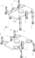
図6は、車台11などを真上から見た状態を示しており、車台11の左右両側に六組の可動脚(21乃至26)が配置されている。個々の可動脚(21乃至26)において、その根元部31は車台11に対して揺動自在に取り付けられており、根元部31の先に中間部41が取り付けられ、中間部41の先に先端部51が取り付けられている。そのほか車台11の四隅には、先の図5で示した安定支持領域Sを描いてある。この安定支持領域Sに関し、車台11の幅方向については、根元部31と中間部41との揺動軸(H1)よりも外側となる。また車台11の前後方向については、前方の可動脚21、22と中央の可動脚23、24との中間位置よりも前方と、後方の可動脚25、26と中央の可動脚23、24との中間位置よりも後方となる。そして車台11が静止している初期状態では、図の左上のように、各可動脚(21乃至26)が車台11の真横に突出しており、それぞれの先端部51が地面に接触している。
FIG. 6 shows the
個々の可動脚(21乃至26)は自在に変形可能であり、図6の右上において、左中央の可動脚23は前方に移動しており、車台11の左前方の安定支持領域Sに接触している。また右中央の可動脚24は後方に移動しており、車台11の右後方の安定支持領域Sに接触している。したがって、左前方の可動脚21と右後方の可動脚26を地面から引き離した場合でも、安定支持領域Sには、四組の可動脚22、23、24、25が接触しており、車台11を安定した状態で支持することができる。このように個々の安定支持領域Sには、少なくとも一組の可動脚(21乃至26)が常時接触した状態を維持しながら個々の可動脚(21乃至26)を変形させることで、車台11の支持が不安定になることを回避できる。
The individual movable legs (21 to 26) can be freely deformed, and in the upper right of FIG. ing. Further, the right center
図6の下方では車台11を斜行させる様子を描いてあり、左下の図において、車台11の右側(図の上方)の可動脚22、24、26は、車台11の外側に大きく突出させており、その接地位置は車台11から遠ざかっている。この状態において、車台11の左側(図の下方)の可動脚21、23、25の中間部41を横倒しにするほか、右側の可動脚22、24、26の中間部41を直立させることで、車台11が右側(図の上方)に横行することになる。さらにこの横行の際、全ての可動脚(21乃至26)の根元部31を回転させることで、前後方向の移動を伴うことになり、車台11の斜行が実現する。そして車台11を斜行させる過程においても、個々の安定支持領域Sには、少なくとも一組の可動脚(21乃至26)が常時接地した状態を維持することで、車台11の安定性を高めることができる。ただし車台11の安定性に問題がない状況においては、安定支持領域Sを考慮することのない移動も可能である。
The lower part of FIG. 6 shows how the
図7から図11は、本発明による不整地移動装置において、安定性を重視した「安定移動方法」を時系列で示しており、図7から図11に進むに連れて時間が経過していく。この移動方法は、安定性を重視する観点から、常時、四組以上の可動脚(21乃至26)が地面に接触していることを特徴とする。そして図7の上方は、移動前の初期状態であり、全ての可動脚(21乃至26)は、車台11の真横に突出しており、しかも地面に接触している。その後、図の下方のように、中央に位置する左右二組の可動脚23、24を地面から引き離し、さらに前方に回転させる。この段階では、前後の四組の可動脚21、22、25、26で車台11が支持されている。なお可動脚(21乃至26)を地面から引き離した際は、その中間部41が根元部31の上方に突出するほか、中間部41と先端部51は密着し、折り畳まれたような状態になる。
FIGS. 7 to 11 show in chronological order a "stable movement method" that emphasizes stability in the rough terrain moving device according to the present invention, and time passes from FIG. 7 to FIG. 11. . This movement method is characterized in that four or more pairs of movable legs (21 to 26) are always in contact with the ground from the viewpoint of placing emphasis on stability. The upper part of FIG. 7 shows the initial state before movement, in which all the movable legs (21 to 26) protrude directly to the side of the
図8は、図7の後の第二段階を示しており、図の上方では、中央の可動脚23、24を地面に接触させており、図の下方では、前方の可動脚21、22を地面から引き離している。この図の上方のように、中央の二組の可動脚23、24は、不整地移動装置の重心よりも前方で地面に接触しており、この接触位置は、先の図5に示す安定支持領域Sの中である。したがって中央の二組の可動脚23、24と、後方の二組の可動脚25、26の四組だけで車台11を支持可能になる。そこで図の下方のように、前方の二組の可動脚21、22を地面から引き離し、さらに前方に回転させることができる。
FIG. 8 shows the second stage after FIG. 7. In the upper part of the figure, the central
図9は、図8の後の第三段階を示しており、図の上方では、前方の可動脚21、22を地面に接触させており、図の下方では、車台11を前進させている。この図の上方のように、前方の二組の可動脚21、22を地面に接触させると、全ての可動脚(21乃至26)が地面に接触した状態になるが、この際、四組の可動脚21、22、23、24は前方に突出している。その後、全ての可動脚(21乃至26)の根元部31を同時に回転させ、併せて可動脚(21乃至26)の姿勢を個別に微調整することで、車台11が円滑に押し出され、図の下方のように車台11が前進する。そして前進を終えると、前方と中央の四組の可動脚21、22、23、24は、車台11の真横に突出しており、後方の二組の可動脚25、26は、後方に突出している。
FIG. 9 shows the third stage after FIG. 8, in which the front
図9のように、可動脚(21乃至26)の根元部31を回転させて車台11を前進させる際、各接地体58は、根元部31の回転中心を原点として円運動することになるが、この円運動に伴い、車台11の側面から接地体58までの距離が変化することになる。具体的には、根元部31が車台11の前方または後方に突出した状態では、車台11の側面から接地体58までの距離が近づくのに対し、根元部31が真横に突出した状態では、車台11の側面から接地体58までの距離が遠くなる。そしてこの距離の差により、接地体58は地面と擦れ合いながら移動するため、エネルギー消費の増大などを引き起こす。この事態を回避するため、根元部31の回転と同期するように中間部41や先端部51の姿勢を微調整しており、接地体58と地面との擦れ合いを抑え込む。
As shown in FIG. 9, when the
図10は、図9の後の第四段階を示しており、図の上方では、中央の可動脚23、24を地面から引き離しており、図の下方では、中央の可動脚23、24を地面に接触させている。この図の上方のように、中央の二組の可動脚23、24を地面から引き離した場合でも、残る四組の可動脚21、22、25、26が地面に接触しており、車台11の支持には何らの影響も与えない。そして、中央の二組の可動脚23、24を後方に回転させた後、地面に接触させることになるが、この接触位置は、先の図5に示す安定支持領域Sの中である。以降、図の下方のように、全ての可動脚(21乃至26)が地面に接触した状態になるが、中央の二組の可動脚23、24と、後方の二組の可動脚25、26は、車台11の後方に突出している。この際、中央の二組の可動脚23、24は、前記のように安定支持領域Sの中に接触している。したがって中央の二組の可動脚23、24と、前方の二組の可動脚21、22の四組だけで車台11を支持可能になる。
FIG. 10 shows the fourth stage after FIG. 9, in which the middle
図11は、図10の後の最終段階を示しており、図の上方では、後方の可動脚25、26を地面から引き離しており、図の下方では、後方の可動脚25、26を地面に接触させている。この図のように、中央の二組の可動脚23、24は、後方に突出した状態で地面に接触している。そのため、この図の上方のように、後方の二組の可動脚25、26を地面から引き離した場合でも、車台11の支持には何らの影響も与えない。そこで後方の二組の可動脚25、26を地面から引き離した後に前方に回転させ、さらに地面に接触させると、図の下方のような状態になる。この際、後方の二組の可動脚25、26は、真横に突出させる。以降、中央の二組の可動脚23、24を地面から引き離すと、図7の状態に戻る。したがって、図7から図11に示す一連の動作を留まることなく連続して繰り返すことで、安定した状態での移動が実現する。
FIG. 11 shows the final stage after FIG. 10, in which the rear
図12および図13は、本発明による不整地移動装置において、高速性を重視した「高速移動方法」を時系列で示しており、図12の後に図13の状態になる。この移動方法では、全ての可動脚(21乃至26)のうち、三組だけを地面に接触させた状態を許容しており、図12の上方では、右前方の可動脚22と左中央の可動脚23と右後方の可動脚26を地面に接触させ、残りの三組の可動脚21、24、25を地面から引き離している。しかも全ての可動脚(21乃至26)は、前方に突出させた状態としてある。その後、地面に接触している三組の可動脚22、23、26の根元部31を回転させ、併せてこれらの可動脚22、23、26の姿勢を個別に微調整すると、図の下方のように車台11が前進する。
FIGS. 12 and 13 show in chronological order a "high-speed movement method" that emphasizes high speed in the rough terrain moving device according to the present invention, and the state shown in FIG. 13 occurs after FIG. 12. This movement method allows only three sets of all the movable legs (21 to 26) to be in contact with the ground, and in the upper part of FIG. The
図13は、図12の後の段階を示しており、図の上方では、三組の可動脚21、24、25を地面に接触させ、残る三組の可動脚22、23、26を地面から引き離しており、図の下方では、車台11を前進させている。図12の下方に示した状態の後、それまで地面から引き離されていた三組の可動脚21、24、25を地面に接触させ、次に残る三組の可動脚22、23、26を地面から引き離した後に前方に回転させると、図13の上方のような状態になる。以降、地面に接触している三組の可動脚21、24、25の根元部31を回転させ、併せてこれらの可動脚21、24、25の姿勢を個別に微調整すると、図13の下方のように車台11が前進する。その後、地面から引き離されていた三組の可動脚22、23、26を地面に接触させ、次に残る三組の可動脚21、24、25を地面から引き離した後に前方に回転させると、先の図12の状態に戻る。したがって、図12と図13に示す一連のサイクルを留まることなく連続して繰り返すことで、高速での移動が実現する。なおこのような移動方法は、六組の可動脚(21乃至26)のうち、半分だけで不整地移動装置を支持することになる。そのため重心が車台11の中心付近に留まり、しかも平坦な地面において実現可能である。
13 shows a stage after FIG. 12, in the upper part of the figure, three sets of
図14は、地面の段差に可動脚(21乃至26)が追従する様子を示している。個々の可動脚(21乃至26)は自在に変形可能であるため、この図のように地面の局地的な段差に対し、無理なく追従することができる。また周辺の地面全体が傾斜している場合でも、個々の可動脚(21乃至26)を自在に変形させることで、車台11を水平に維持することができる。
FIG. 14 shows how the movable legs (21 to 26) follow a step on the ground. Since the individual movable legs (21 to 26) can be freely deformed, they can easily follow local differences in level on the ground as shown in this figure. Furthermore, even if the entire surrounding ground is sloped, the
図15は、可動脚(21乃至26)を最大限外側に突出させた状態を示している。本発明による不整地移動装置を用いて各種作業を行う際、立木や土砂などを保持することで重心が大きく変化することがある。そのような状況でも安定性を確保できるよう、個々の可動脚(21乃至26)は、できるだけ車台11から離れた位置に到達できることが望ましい。そこでこの図のように、中間部41と先端部51を直線状に配置することで、地面との接触位置を車台11から遠ざけることができる。
FIG. 15 shows a state in which the movable legs (21 to 26) are projected outward to the maximum extent. When performing various types of work using the rough terrain moving device according to the present invention, the center of gravity may change significantly due to holding of standing trees, earth, and sand. In order to ensure stability even in such a situation, it is desirable that the individual movable legs (21 to 26) be able to reach a position as far away from the
図16と図17と図18は、本発明による不整地移動装置を安定した状態で横行させる過程を示している。本発明では、タイヤや無限軌道を用いていないため、前後方向の移動を伴うことなく純粋に横行させることも容易である。この横行に先立ち、車台11の一側面に並ぶ可動脚21、23、25は、車台11の遠方で地面に接触させる必要があり、図16では、車台11の左前方の可動脚21を遠方に突出させる過程を描いてある。この図の上方では、可動脚21が地面から引き離されており、しかもその根元部31は車台11の真横に突出しているが、この可動脚21を地面から引き離すのに先立ち、その後方の可動脚23を前方に移動させ、可動脚21の代替として車台11を支持させる。その後、この図の下方のように、可動脚21の中間部41を概ね水平方向に突出させ、この可動脚21の先端部51を車台11の遠方で地面に接触させる。これ以降、左中央の可動脚23は、地面から引き離しても構わない。
16, 17, and 18 show the process of traversing the rough terrain moving device according to the present invention in a stable state. In the present invention, since tires and endless tracks are not used, it is easy to move the vehicle purely horizontally without any movement in the front-rear direction. Prior to this traverse, the
図17は、図16の後の第二段階を示しており、車台11の左後方の可動脚25を遠方に突出させる過程を描いてある。この図の上方では、可動脚25が地面から引き離されており、しかもその根元部31は車台11の真横に突出しているが、この可動脚25を地面から引き離すのに先立ち、その前方の可動脚23を後方に移動させ、可動脚25の代替として車台11を支持させる。その後、この図の下方のように、可動脚25の中間部41を概ね水平方向に突出させ、この可動脚25の先端部51を車台11の遠方で地面に接触させる。これ以降、左中央の可動脚23は、地面から引き離しても構わないため、その前後に隣接する可動脚21、25と同様、その根元部31を車台11の真横に突出させるほか、その先端部51を車台11の遠方で地面に接触させる。
FIG. 17 shows the second stage after FIG. 16, and depicts the process of causing the left rear
図18は、図17の後の第三段階を示しており、各可動脚(21乃至26)を同時に変形させて車台11を横行させる過程を描いてある。この図の上方では、全ての可動脚(21乃至26)が地面に接触しているが、車台11の左側面(図の右下側)に並ぶ可動脚21、23、25の中間部41は、概ね水平方向に突出しており、これらの先端部51は車台11の遠方で地面に接触している。しかし車台11の右側面(図の左上側)に並ぶ可動脚22、24、26の中間部41は、概ね直立しており、これらの先端部51は車台11の近傍で地面に接触している。その後、車台11の左側の三箇所の中間部41を直立するように変形させ、同時に、車台11の右側の三箇所の中間部41を横倒しするように変形させると、図の下方のように、車台11が横行することになる。
FIG. 18 shows the third stage after FIG. 17, and depicts a process in which the movable legs (21 to 26) are simultaneously deformed to cause the
なお図16と図17と図18では、車台11の安定性を確保するため、先の図5で示した安定支持領域Sを考慮しており、個々の安定支持領域Sには、少なくとも一組の可動脚(21乃至26)が常時接地した状態を維持している。ただし車台11の安定性に問題がない状況においては、安定支持領域Sを考慮することのない横行も可能である。そのほか図18では、中間部41を変形させて車台11を横行させる際、全ての可動脚(21乃至26)を地面に接触させているが、バランスに問題がなければ、その一部を地面から引き離しても構わない。
Note that in FIGS. 16, 17, and 18, in order to ensure the stability of the
図19は、各可動脚(21乃至26)を同時に変形させて不整地移動装置を斜行させる状態を示している。この図の上方は、先の図18の上方と同じ状態であり、全ての可動脚(21乃至26)が地面に接触しているが、車台11の左側面(図の右下側)に並ぶ可動脚21、23、25の中間部41は、概ね水平方向に突出しており、これらの先端部51は車台11の遠方で地面に接触している。しかし車台11の右側面(図の左上側)に並ぶ可動脚22、24、26の中間部41は、概ね直立しており、これらの先端部51は車台11の近傍で地面に接触している。
FIG. 19 shows a state in which each of the movable legs (21 to 26) is simultaneously deformed and the rough terrain moving device is moved diagonally. The upper part of this figure is in the same state as the upper part of Figure 18, in which all the movable legs (21 to 26) are in contact with the ground, but are lined up on the left side of the chassis 11 (lower right side in the figure). The
その後、先の図18と同様、車台11の左側の三箇所の中間部41を直立するように変形させ、同時に、車台11の右側の三箇所の中間部41を横倒しするように変形させるが、この中間部41の変形と同期して全ての可動脚(21乃至26)を回転させると、図の下方のように、車台11を斜行させることができる。なお斜行時についても、バランスに問題がなければ、一部の可動脚(21乃至26)を地面から引き離しても構わない。
Thereafter, as in FIG. 18, the three
図20は、不整地移動装置を斜行させる過程の一例を示しているが、ここでは車台11などを真上から見た状態で描いてあり、矢印の順に個々の可動脚(21乃至26)を変形させていく。そしてこの図の左上は、移動前の初期状態であり、車台11の安定性を増大させるため、前方の二組の可動脚21、22をやや前方(図の左側)に傾けているほか、後方の二組の可動脚25、26をやや後方(図の右側)に傾けている。このように車台11が静止している状態については、これまでの各図のように、全ての可動脚(21乃至26)を車台11の真横に突出させる場合もあれば、この図のように、車台11の四隅方向に突出させ、安定性を一段と向上させる場合もある。さらに障害物の回避などのため、個別に変形させる場合もある。
FIG. 20 shows an example of the process of moving the rough terrain moving device diagonally. Here, the
図の左上の状態の後、斜行の準備のため、図の右上のように、中央の二組の可動脚23、24を前方に移動させる。その結果、車台11の安定性を維持しながら前方の二組の可動脚21、22を自在に移動させることができ、右前方の可動脚22を車台11の右前方に突出させるほか、左前方の可動脚21をやや後方に移動させ、併せて車台11に接近させる。次に図の右中程のように、中央の二組の可動脚23、24を後方に移動させると、車台11は前方と中央の四組の可動脚21、22、23、24で支持可能になり、後方の二組の可動脚25、26を自在に移動させることができる。そこで図の左中程のように、右後方の可動脚26を右前方に突出させるほか、左後方の可動脚25をやや後方に移動させ、併せて車台11に接近させる。
After the state in the upper left of the figure, the two sets of
その後、中央の二組の可動脚23、24を変形させると、図の左下のように、車台11の右側に並ぶ三組の可動脚22、24、26は、車台11の前方に突出し、且つ車台11から離れた位置で地面と接触している。対して車台11の左側に並ぶ三組の可動脚21、23、25は、車台11の後方側を向いており、且つ車台11の近傍で地面と接触している。そして最後には、車台11の右側に並ぶ可動脚22、24、26の中間部41を横倒しにするほか、これと同期して左側に並ぶ可動脚21、23、25の中間部41を直立させると、図の右下のように、車台11の斜行が実現する。なおここでは、可動脚(21乃至26)の根元部31を回転させることなく斜行を実現している。
After that, when the two sets of
これまでの各図のように、本発明による不整地移動装置は、各可動脚(21乃至26)の根元部31や中間部41を個別に制御することを前提としており、車台11を前後左右のあらゆる方向に移動させることができる。また、地面の傾斜や起伏に無理なく追従できるほか、立木などの障害物の回避も容易であり、林業や治山事業のような過酷な現場においても、安定した移動を実現することができる。
As shown in the previous figures, the rough terrain moving device according to the present invention is based on the premise that the
11 車台
13 台座
15 ターンテーブル
21 可動脚(左前方)
22 可動脚(右前方)
23 可動脚(左中央)
24 可動脚(右中央)
25 可動脚(左後方)
26 可動脚(右後方)
31 根元部
32 進退シリンダ
34 上方シリンダ
35 リンク(上方シリンダと根元部を結ぶもの)
41 中間部
44 下方シリンダ
45 リンク(上方シリンダと中間部を結ぶもの)
46 窓
51 先端部
56 窓
57 加振部
58 接地体
61 車体
62 操作席
64 アーム
65 ハーベスタ
68 コントローラ
71 接続軸
72 ピン
73 脚首体
74 固定リング
75 接地板
76 ボルト
C 重心
H1 水平軸(根元部と中間部との揺動軸)
H2 水平軸(中間部と先端部との揺動軸)
S 安定支持領域
V 垂直軸(根元部の回転中心)
11 Chassis 13 Pedestal 15
22 Movable legs (front right)
23 Movable legs (center left)
24 Movable legs (center right)
25 Movable leg (left rear)
26 Movable legs (rear right)
31 Root portion 32 Advance/retreat cylinder 34 Upper cylinder 35 Link (connecting the upper cylinder and the root portion)
41 Middle part 44 Lower cylinder 45 Link (connecting the upper cylinder and the middle part)
46
H2 horizontal axis (swing axis between the middle part and the tip part)
S Stable support area V Vertical axis (center of rotation at the base)
Claims (4)
前記車台(11)の左右それぞれの側面には、三組の前記可動脚(21乃至26)が前後方向に間隔を空けて配置してあり、
個々の前記可動脚(21乃至26)は、根元部(31)と中間部(41)と先端部(51)の三要素が直列状に並んでおり、
前記根元部(31)は、前記車台(11)の側面に配置してあり、且つ該車台(11)に対して垂直軸(V)を中心として揺動可能であり、
前記中間部(41)は、その一端側が前記根元部(31)の端部に取り付けられ且つ該根元部(31)に対して水平軸(H1)を中心として揺動可能であり、
前記先端部(51)は、前記中間部(41)の両端部のうち前記根元部(31)の反対側に取り付けられ且つ該中間部(41)に対して水平軸(H2)を中心として揺動可能であり、該先端部(51)において該中間部(41)の反対側は地面と接触し、
個々の前記可動脚(21乃至26)は、他と連動することなく変形可能で、特定の前記先端部(51)だけを地面から引き離すことが可能であり、さらに地面に接触している全ての該可動脚(21乃至26)の前記根元部(31)を同時に回転させることで前記車台(11)を移動させることができ、
前記可動脚(21乃至26)が地面に接触し且つ前記車台(11)が静止している初期状態において、前記根元部(31)は、該車台(11)の側面から遠ざかる方向に伸びており、また前記先端部(51)は、該根元部(31)の端部から見て下方且つ該車台(11)から一段と遠ざかった位置で垂直方向に伸びており、残る前記中間部(41)は、該先端部(51)に向けて該車台(11)から遠ざかるように斜め下方に伸びていることを特徴とする不整地移動装置。 A vehicle platform (11) arranged to face the ground, six sets of movable legs (21 to 26) for supporting the vehicle platform (11) in the air, and a vehicle body (61) mounted on the vehicle platform (11). It consists of,
Three sets of movable legs (21 to 26) are arranged at intervals in the front and rear direction on each of the left and right side surfaces of the chassis (11),
Each of the movable legs (21 to 26) has three elements arranged in series: a root part (31), an intermediate part (41), and a tip part (51),
The base portion (31) is arranged on a side surface of the chassis (11) and is swingable about a vertical axis (V) with respect to the chassis (11),
The intermediate portion (41) has one end attached to the end of the root portion (31) and is swingable about the horizontal axis (H1) with respect to the root portion (31),
The tip portion (51) is attached to the opposite side of the root portion (31) of both ends of the intermediate portion (41), and is oscillating about a horizontal axis (H2) with respect to the intermediate portion (41). the tip portion (51) is in contact with the ground on the opposite side of the intermediate portion (41);
Each of the movable legs (21 to 26) can be deformed without interlocking with the others, and only a specific tip (51) can be pulled away from the ground, and all movable legs (21 to 26) that are in contact with the ground can be moved away from the ground. By simultaneously rotating the base portions (31) of the movable legs (21 to 26), the vehicle platform (11) can be moved;
In an initial state in which the movable legs (21 to 26) are in contact with the ground and the chassis (11) is stationary, the root portion (31) extends in a direction away from the side surface of the chassis (11). Further, the tip portion (51) extends vertically at a position downward and further away from the chassis (11) when viewed from the end of the base portion (31), and the remaining intermediate portion (41) , an uneven terrain moving device extending obliquely downward toward the tip end (51) and away from the vehicle platform (11) .
前記車台(11)と対峙する地面において、該不整地移動装置の重心(C)位置の外側には、該車台(11)の左前方および右前方および左後方および右後方の四箇所からなる安定支持領域(S)を想定し、
個々の該安定支持領域(S)には、一組以上の前記可動脚(21乃至26)が接触している状態を維持する安定移動方法と、
該安定支持領域(S)に依存することなく、該車台(11)の左側または右側のいずれか一方は、その中央に位置する該可動脚(23または24)だけが地面に接触している状態を許容する高速移動方法と、の二つの移動方法を切り替え可能としたことを特徴とする不整地移動装置の制御方法。 A control method for moving the rough terrain moving device according to claim 1 or 2 in the front and back direction,
On the ground facing the vehicle platform (11), outside the center of gravity (C) of the rough terrain moving device, there is a stable structure consisting of four locations: left front, right front, left rear, and right rear of the vehicle platform (11). Assuming the support area (S),
a stable movement method that maintains one or more sets of the movable legs (21 to 26) in contact with each of the stable support areas (S);
Regardless of the stable support area (S), either the left or right side of the chassis (11) is in a state where only the movable leg (23 or 24) located in the center is in contact with the ground. A method for controlling an uneven terrain moving device, characterized in that it is possible to switch between two moving methods: a high-speed moving method that allows
前記車台(11)と対峙する地面において、該不整地移動装置の重心(C)位置の外側には、該車台(11)の左前方および右前方および左後方および右後方の四箇所からなる安定支持領域(S)を想定し、
個々の該安定支持領域(S)には、一組以上の前記可動脚(21乃至26)が接触している状態を維持しながら個々の該可動脚(21乃至26)を変形させていき、少なくとも該車台(11)の四隅に位置する四組の該可動脚(21、22、25、26)を地面に接触させ、
その後、個々の該安定支持領域(S)には、一組以上の該可動脚(21乃至26)が接触している状態を維持しながら、地面に接触している該可動脚(21乃至26)の前記根元部(31)と前記中間部(41)の両方または該中間部(41)だけを変形させ、該車台(11)を移動させることを特徴とする不整地移動装置の制御方法。 A control method for moving the rough terrain moving device according to claim 1 or 2 in any direction,
On the ground facing the vehicle platform (11), outside the center of gravity (C) of the rough terrain moving device, there is a stable structure consisting of four locations: left front, right front, left rear, and right rear of the vehicle platform (11). Assuming the support area (S),
Deforming each of the movable legs (21 to 26) while maintaining a state in which one or more of the movable legs (21 to 26) are in contact with each of the stable support regions (S), At least the four sets of movable legs (21, 22, 25, 26) located at the four corners of the chassis (11) are brought into contact with the ground;
Thereafter, one or more sets of the movable legs (21 to 26) remain in contact with each of the stable support areas (S), and the movable legs (21 to 26) that are in contact with the ground are ) A control method for an uneven terrain moving device, characterized in that the vehicle platform (11) is moved by deforming both the base portion (31) and the intermediate portion (41) or only the intermediate portion (41) of the vehicle.
Priority Applications (2)
| Application Number | Priority Date | Filing Date | Title |
|---|---|---|---|
| JP2020218054A JP7376207B2 (en) | 2020-12-25 | 2020-12-25 | Rough terrain moving device and its control method |
| JP2023181143A JP2024003802A (en) | 2020-12-25 | 2023-10-20 | Off road movement device and control method therefor |
Applications Claiming Priority (1)
| Application Number | Priority Date | Filing Date | Title |
|---|---|---|---|
| JP2020218054A JP7376207B2 (en) | 2020-12-25 | 2020-12-25 | Rough terrain moving device and its control method |
Related Child Applications (1)
| Application Number | Title | Priority Date | Filing Date |
|---|---|---|---|
| JP2023181143A Division JP2024003802A (en) | 2020-12-25 | 2023-10-20 | Off road movement device and control method therefor |
Publications (2)
| Publication Number | Publication Date |
|---|---|
| JP2022102963A JP2022102963A (en) | 2022-07-07 |
| JP7376207B2 true JP7376207B2 (en) | 2023-11-08 |
Family
ID=82273703
Family Applications (2)
| Application Number | Title | Priority Date | Filing Date |
|---|---|---|---|
| JP2020218054A Active JP7376207B2 (en) | 2020-12-25 | 2020-12-25 | Rough terrain moving device and its control method |
| JP2023181143A Pending JP2024003802A (en) | 2020-12-25 | 2023-10-20 | Off road movement device and control method therefor |
Family Applications After (1)
| Application Number | Title | Priority Date | Filing Date |
|---|---|---|---|
| JP2023181143A Pending JP2024003802A (en) | 2020-12-25 | 2023-10-20 | Off road movement device and control method therefor |
Country Status (1)
| Country | Link |
|---|---|
| JP (2) | JP7376207B2 (en) |
Citations (5)
| Publication number | Priority date | Publication date | Assignee | Title |
|---|---|---|---|---|
| JP2003266336A (en) | 2002-03-12 | 2003-09-24 | Japan Science & Technology Corp | Multileg walking robot |
| JP2009101469A (en) | 2007-10-24 | 2009-05-14 | Tokyo Institute Of Technology | Legged mobile work device |
| JP2014100767A (en) | 2012-11-20 | 2014-06-05 | Toshiba Corp | Level difference walking control device and method of multileg walking robot |
| JP6135358B2 (en) | 2013-07-24 | 2017-05-31 | 日本電気株式会社 | Antenna and method for manufacturing antenna |
| JP2019089192A (en) | 2017-11-14 | 2019-06-13 | 学校法人 芝浦工業大学 | Movable body |
-
2020
- 2020-12-25 JP JP2020218054A patent/JP7376207B2/en active Active
-
2023
- 2023-10-20 JP JP2023181143A patent/JP2024003802A/en active Pending
Patent Citations (5)
| Publication number | Priority date | Publication date | Assignee | Title |
|---|---|---|---|---|
| JP2003266336A (en) | 2002-03-12 | 2003-09-24 | Japan Science & Technology Corp | Multileg walking robot |
| JP2009101469A (en) | 2007-10-24 | 2009-05-14 | Tokyo Institute Of Technology | Legged mobile work device |
| JP2014100767A (en) | 2012-11-20 | 2014-06-05 | Toshiba Corp | Level difference walking control device and method of multileg walking robot |
| JP6135358B2 (en) | 2013-07-24 | 2017-05-31 | 日本電気株式会社 | Antenna and method for manufacturing antenna |
| JP2019089192A (en) | 2017-11-14 | 2019-06-13 | 学校法人 芝浦工業大学 | Movable body |
Also Published As
| Publication number | Publication date |
|---|---|
| JP2022102963A (en) | 2022-07-07 |
| JP2024003802A (en) | 2024-01-15 |
Similar Documents
| Publication | Publication Date | Title |
|---|---|---|
| JP5288998B2 (en) | Leveling equipment for forestry machines and excavators | |
| US4241803A (en) | Wheel-support assembly for rolling and stepping vehicles, especially cranes, excavating machinery and the like | |
| CN107140052A (en) | A kind of wheel leg type Hexapod Robot with suspension | |
| CN111976859B (en) | UPS-based parallel-connection wheel-foot mobile robot | |
| CN110949554B (en) | Leveling device of crawler carrier | |
| JPS60255581A (en) | Travelling device | |
| AU2018236042B2 (en) | A tracked vehicle comprising a pendulum arm chassis suspension | |
| CN105216899A (en) | Barrier-surpassing robot | |
| CN205469357U (en) | A multi -functional imitative ant robot for crossing over obstacle | |
| CN103661662A (en) | Walking type chassis of symmetrical type multi-freedom-degree four-wheel all-wheel-drive walking type excavator | |
| CN108082458B (en) | Self-adaptive undercarriage | |
| CN101340813A (en) | Agricultural implement comprising an improved hitch structure | |
| CN104015833A (en) | Robot walking leg mechanism with integration of wheel type, foot type and wheel-foot composite type | |
| CN110087978A (en) | Caterpillar including rotatable attachment bogie | |
| JP7376207B2 (en) | Rough terrain moving device and its control method | |
| JP2006142465A (en) | Biped locomotion robot and walking control method | |
| US6343799B1 (en) | Tilt mechanism for work machine | |
| CN107244358B (en) | Caterpillar band travelling mechanism | |
| EP1340670B1 (en) | Independent wheel module and vehicle using such a module | |
| CN107651033A (en) | A kind of leg wheel hybrid hydraulic pedipulator | |
| JP5936194B2 (en) | Inclined work machine | |
| CN114313041A (en) | Whole-vehicle hydraulic anti-tilt control mechanism of unmanned crawler | |
| CN207106679U (en) | A kind of robot multi-link lever suspension fork wheel and single hop crawler type walking mechanism | |
| JP2003073076A (en) | Crane working vehicle, method of changing direction of the vehicle, and slope seeding and planting method by using the vehicle | |
| JPH0487891A (en) | Machine body control device in crawler traveling vehicle |
Legal Events
| Date | Code | Title | Description |
|---|---|---|---|
| A621 | Written request for application examination |
Free format text: JAPANESE INTERMEDIATE CODE: A621 Effective date: 20220825 |
|
| A977 | Report on retrieval |
Free format text: JAPANESE INTERMEDIATE CODE: A971007 Effective date: 20230630 |
|
| A131 | Notification of reasons for refusal |
Free format text: JAPANESE INTERMEDIATE CODE: A131 Effective date: 20230711 |
|
| A521 | Request for written amendment filed |
Free format text: JAPANESE INTERMEDIATE CODE: A523 Effective date: 20230818 |
|
| TRDD | Decision of grant or rejection written | ||
| A01 | Written decision to grant a patent or to grant a registration (utility model) |
Free format text: JAPANESE INTERMEDIATE CODE: A01 Effective date: 20230926 |
|
| A61 | First payment of annual fees (during grant procedure) |
Free format text: JAPANESE INTERMEDIATE CODE: A61 Effective date: 20231020 |
|
| R150 | Certificate of patent or registration of utility model |
Ref document number: 7376207 Country of ref document: JP Free format text: JAPANESE INTERMEDIATE CODE: R150 |