JP7375160B2 - door opener for vehicle - Google Patents
door opener for vehicle Download PDFInfo
- Publication number
- JP7375160B2 JP7375160B2 JP2022505919A JP2022505919A JP7375160B2 JP 7375160 B2 JP7375160 B2 JP 7375160B2 JP 2022505919 A JP2022505919 A JP 2022505919A JP 2022505919 A JP2022505919 A JP 2022505919A JP 7375160 B2 JP7375160 B2 JP 7375160B2
- Authority
- JP
- Japan
- Prior art keywords
- operating lever
- switch
- angular range
- elastic body
- sliding surface
- Prior art date
- Legal status (The legal status is an assumption and is not a legal conclusion. Google has not performed a legal analysis and makes no representation as to the accuracy of the status listed.)
- Active
Links
- 230000007423 decrease Effects 0.000 claims description 14
- 230000005540 biological transmission Effects 0.000 claims description 3
- 238000009751 slip forming Methods 0.000 claims description 2
- 238000010586 diagram Methods 0.000 description 15
- 230000035807 sensation Effects 0.000 description 3
- 230000008602 contraction Effects 0.000 description 2
- 210000000707 wrist Anatomy 0.000 description 2
- 238000013459 approach Methods 0.000 description 1
- 230000006835 compression Effects 0.000 description 1
- 238000007906 compression Methods 0.000 description 1
- 230000006870 function Effects 0.000 description 1
- 238000000034 method Methods 0.000 description 1
- 238000012986 modification Methods 0.000 description 1
- 230000004048 modification Effects 0.000 description 1
- 230000000284 resting effect Effects 0.000 description 1
- 230000015541 sensory perception of touch Effects 0.000 description 1
Images


Classifications
-
- E—FIXED CONSTRUCTIONS
- E05—LOCKS; KEYS; WINDOW OR DOOR FITTINGS; SAFES
- E05B—LOCKS; ACCESSORIES THEREFOR; HANDCUFFS
- E05B81/00—Power-actuated vehicle locks
- E05B81/54—Electrical circuits
- E05B81/56—Control of actuators
-
- E—FIXED CONSTRUCTIONS
- E05—LOCKS; KEYS; WINDOW OR DOOR FITTINGS; SAFES
- E05B—LOCKS; ACCESSORIES THEREFOR; HANDCUFFS
- E05B79/00—Mounting or connecting vehicle locks or parts thereof
- E05B79/10—Connections between movable lock parts
- E05B79/20—Connections between movable lock parts using flexible connections, e.g. Bowden cables
-
- B—PERFORMING OPERATIONS; TRANSPORTING
- B60—VEHICLES IN GENERAL
- B60J—WINDOWS, WINDSCREENS, NON-FIXED ROOFS, DOORS, OR SIMILAR DEVICES FOR VEHICLES; REMOVABLE EXTERNAL PROTECTIVE COVERINGS SPECIALLY ADAPTED FOR VEHICLES
- B60J5/00—Doors
-
- E—FIXED CONSTRUCTIONS
- E05—LOCKS; KEYS; WINDOW OR DOOR FITTINGS; SAFES
- E05B—LOCKS; ACCESSORIES THEREFOR; HANDCUFFS
- E05B79/00—Mounting or connecting vehicle locks or parts thereof
- E05B79/10—Connections between movable lock parts
- E05B79/22—Operative connections between handles, sill buttons or lock knobs and the lock unit
-
- E—FIXED CONSTRUCTIONS
- E05—LOCKS; KEYS; WINDOW OR DOOR FITTINGS; SAFES
- E05B—LOCKS; ACCESSORIES THEREFOR; HANDCUFFS
- E05B81/00—Power-actuated vehicle locks
- E05B81/54—Electrical circuits
- E05B81/64—Monitoring or sensing, e.g. by using switches or sensors
- E05B81/76—Detection of handle operation; Detection of a user approaching a handle; Electrical switching actions performed by door handles
-
- E—FIXED CONSTRUCTIONS
- E05—LOCKS; KEYS; WINDOW OR DOOR FITTINGS; SAFES
- E05B—LOCKS; ACCESSORIES THEREFOR; HANDCUFFS
- E05B81/00—Power-actuated vehicle locks
- E05B81/54—Electrical circuits
- E05B81/90—Manual override in case of power failure
-
- E—FIXED CONSTRUCTIONS
- E05—LOCKS; KEYS; WINDOW OR DOOR FITTINGS; SAFES
- E05B—LOCKS; ACCESSORIES THEREFOR; HANDCUFFS
- E05B85/00—Details of vehicle locks not provided for in groups E05B77/00 - E05B83/00
- E05B85/10—Handles
- E05B85/12—Inner door handles
-
- E—FIXED CONSTRUCTIONS
- E05—LOCKS; KEYS; WINDOW OR DOOR FITTINGS; SAFES
- E05B—LOCKS; ACCESSORIES THEREFOR; HANDCUFFS
- E05B85/00—Details of vehicle locks not provided for in groups E05B77/00 - E05B83/00
- E05B85/10—Handles
- E05B85/103—Handles creating a completely closed wing surface
Landscapes
- Engineering & Computer Science (AREA)
- Mechanical Engineering (AREA)
- Rotary Switch, Piano Key Switch, And Lever Switch (AREA)
Description
本発明は、車両用のドアオープナーに関するものである。 The present invention relates to a door opener for a vehicle.
自動車等の車両のドアにはドアハンドルやレバーなどの操作部材を備えたドアオープナーが設けられている。このようなドアオープナーは、操作部材を所定量操作することにより、操作部材に接続されたスイッチがオンとなり制御信号が生成されて、ドアロックが電気的に解除される。そして緊急時には、更に、所定量よりも大きな操作をすることにより、機械的にもドアロックが解除される方法が取られており、多段スイッチとして動作する。 2. Description of the Related Art Doors of vehicles such as automobiles are provided with door openers that include operating members such as door handles and levers. In such a door opener, by operating the operating member by a predetermined amount, a switch connected to the operating member is turned on, a control signal is generated, and the door lock is electrically released. In the event of an emergency, a method is adopted in which the door lock is mechanically released by performing a larger operation than a predetermined amount, and the door lock operates as a multi-stage switch.
従来では、ドアロックを解除するために多段スイッチとして動作するドアオープナーが設けられていた。しかし、このようなドアオープナーはドアを電気的に駆動させる駆動部と、操作力を駆動力として用いることによってドアを駆動させる機械的なリンク機構と、を共に備えたドアを操作するためにも用いることができる。 In the past, a door opener was provided that operated as a multi-stage switch to unlock the door. However, such a door opener is also used to operate a door, which is equipped with both a drive part that electrically drives the door and a mechanical link mechanism that drives the door by using the operating force as the driving force. Can be used.
ところで、このようなドアオープナーを電気的な駆動部を備えたドアに応用する場合、電気的な駆動部を制御する操作範囲においては、操作部材の操作に必要とされる操作力が小さく維持されるように設定される。また、機械的なリンク機構を用いてドアを駆動させる操作範囲においては、駆動部を電動で駆動させる操作範囲において必要とされる操作力と比較して、操作部材の操作に必要とされる操作力が大きく設定される。このようにドアを電気的に駆動させる操作を行う操作範囲とドアを機械的に駆動させる操作を行う操作範囲とで操作に必要とされる操作力を明確に異ならせることによって、ドアオープナーを操作する操作者は、操作反力の違いから操作範囲の境界を判別可能になる。そして、操作が終了して操作部材から手が離された後には、操作部材は自動的に初期位置まで復帰する。 By the way, when such a door opener is applied to a door equipped with an electric drive part, the operating force required to operate the operating member is kept small within the operating range that controls the electric drive part. is set to In addition, in the operating range in which the door is driven using a mechanical linkage mechanism, the operating force required to operate the operating member is greater than the operating force required in the operating range in which the drive unit is electrically driven. The force is set to a large value. In this way, by clearly differentiating the operating force required for operation between the operating range for electrically driving the door and the operating range for mechanically driving the door, the door opener can be operated. The operator can determine the boundary of the operation range from the difference in operation reaction force. After the operation is completed and the user's hand is released from the operating member, the operating member automatically returns to its initial position.
しかしながら、特許文献1のレバーバネ18が操作部材であるレバー14の初期位置を開始点としてレバー14の動作に従って弾性力が大きくなるバネであることから、レバー14は、操作角度が増えるに従って操作に必要とされる操作力が右上がりに大きくなる操作部材となっている。そのため、特定の角度範囲において、レバー14の操作に必要とされる操作力が小さく維持されるように設定することは困難であった。また、操作力を小さく設定した角度範囲において、判別しやすい操作感触を生成することは困難であった。そのため、操作力を小さく設定した角度範囲において、電気的な駆動部のスイッチがオンになる前の操作範囲と、電気的な駆動部のスイッチがオンとなる操作範囲とを判別しやすい操作感触を生成することは困難であった。
However, since the lever spring 18 of
本発明は、上記課題を解決するものであり、電気的な駆動部のスイッチがオンになる前の操作範囲と、電気的な駆動部のスイッチがオンとなる操作範囲とにおいて、生成される操作感触を判別しやすい車両用ドアオープナーを提供することを目的とする。 The present invention solves the above-mentioned problem, and the operation generated in the operation range before the switch of the electric drive section is turned on and the operation range when the switch of the electric drive section is turned on. To provide a vehicle door opener whose feel is easy to distinguish.
本実施の形態の一観点によれば、車両用のドアオープナーは、筐体部と、筐体部に回動軸を中心に初期位置と終端位置との間で回動可能な状態で取り付けられている操作レバーと、制御信号を生成する第1のスイッチと、車両のドアを機械的に開く第2のスイッチに接続される接続部と、感触発生機構と、操作レバーを復帰させる復帰用弾性体と、を有し、操作レバーの回動角が、第1の角度範囲では、第1のスイッチ及び第2のスイッチはオフであり、操作レバーの回動角が、第1の角度範囲よりも大きな第2の角度範囲では、第1のスイッチはオンとなり、感触発生機構により感触が生じ、第2のスイッチはオフのままであり、操作レバーの回動角が、第2の角度範囲よりも大きな第3の角度範囲では、第2のスイッチはオンとなる。 According to one aspect of the present embodiment, a door opener for a vehicle includes a housing and is attached to the housing so as to be rotatable about a rotation axis between an initial position and a final position. a first switch that generates a control signal, a connection part that is connected to a second switch that mechanically opens the vehicle door, a feel generating mechanism, and a return elastic that returns the operating lever. The first switch and the second switch are off when the rotation angle of the operation lever is in the first angle range, and the rotation angle of the operation lever is less than the first angle range. In the second angular range where the angle is larger, the first switch is turned on and the tactile generating mechanism generates a tactile sensation, and the second switch remains OFF so that the rotation angle of the operating lever is greater than the second angular range. In the third angular range where the angle is also large, the second switch is turned on.
開示の車両用ドアオープナーによれば、電気的な駆動部のスイッチがオンになる前の操作範囲と、操作力によってドアを機械的に開く操作範囲とにおいて、操作レバーを操作するための操作力を異ならせることが出来る。また、電気的な駆動部のスイッチがオンになる前の操作範囲と、操作力によってドアを機械的に開く操作範囲とにおいて、生成される操作感触を判別し易くすることができる。 According to the disclosed vehicle door opener, the operating force for operating the operating lever is within the operating range before the switch of the electric drive unit is turned on and the operating range where the door is mechanically opened by the operating force. can be made different. Further, it is possible to easily distinguish the generated operational feel between the operational range before the electric drive unit is switched on and the operational range in which the door is mechanically opened by the operational force.
実施するための形態について、以下に説明する。尚、同じ部材等については、同一の符号を付して説明を省略する。また、本実施形態では、各図面において、車両の高さ方向に対応する方向を"上下方向"とし、車両の幅方向に対応する方向を"左右方向"とし、車両の長さ方向に対応する方向を"前後方向"とする。 The embodiment will be described below. Note that the same members and the like are given the same reference numerals and explanations are omitted. In addition, in the present embodiment, in each drawing, a direction corresponding to the height direction of the vehicle is referred to as a "vertical direction", a direction corresponding to the width direction of the vehicle is referred to as a "horizontal direction", and a direction corresponding to the longitudinal direction of the vehicle is referred to as a "horizontal direction". The direction is set as "front-back direction".
(車両用のドアオープナー)
図1に示されるように、本実施の形態における車両用のドアオープナー100は、車両のドア10の内側に設けられたグリップハンドル付きのアームレスト20に取り付けられている。図2は、アームレスト20の斜視図であり、アームレスト20に車両用のドアオープナー100が取り付けられている。また、車両用のドアオープナー100は、車両の運転席に座った操作者が肘または手首をアームレスト20の上面に載せた状態で操作レバー120を回動操作し易いようにアームレスト20の車両内の前方寄りの位置に配置されている。また、車両用のドアオープナー100は、操作者が肘または手首をアームレスト20の上面に載せた状態で操作レバー120を引っ張り操作可能となるように、上方から見て操作レバー120がアームレスト20の上面に設けられた開口部から覗くように配置されている。(Vehicle door opener)
As shown in FIG. 1, a
車両用のドアオープナー100を操作する操作者は、操作レバー120を回動操作することによって電気駆動部(不図示)を駆動させることが出来、その駆動によってドア10を開くことが出来る。また、操作レバー120は不図示のリンク機構を備える機械的スイッチ30に接続されており、車両用のドアオープナー100を操作する操作者は、操作レバー120を回動操作することによって、操作力を機械的スイッチ30に伝達することが出来る。また、当該リンク機構は機械的スイッチ30に伝達された操作力を駆動力としてドア10を開く機能を備えており、車両用のドアオープナー100を操作する操作者は、操作レバー120を回動操作する操作力でドア10を開くことが出来る。尚、当該電気駆動部を駆動させるための操作レバー120の操作角度と、当該リンク機構を駆動させるための操作レバー120の操作角度とは、重ならないように調整されている。
An operator who operates the
図3から図7に基づき、本実施の形態における車両用のドアオープナー100の構造について説明する。尚、図3は、本実施の形態における車両用のドアオープナー100の斜視図であり、図4は右側面図であり、図5は左側面図であり、図6は正面図であり、図7は上面図である。
The structure of the
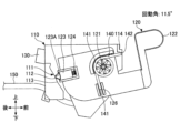
本実施の形態における車両用のドアオープナー100は、筐体部110と、筐体部110に取り付けられた操作レバー120とを有している。操作レバー120は、筐体部110に回動軸121を中心に回動可能な状態で取り付けられており、人が手で操作するための操作部122が設けられている。操作レバー120の操作部122は、図2に示されるように、上方側の面がアームレスト20の上方側に設けられた開口のおよそ半分を塞ぐように配置されている。操作者は、当該開口のうち操作部122によって塞がれていない隙間から指を差し入れることによって、操作部122の前方側の面、及び、下方側の面に触れることが出来る。また、操作者は、操作部122に指を掛けて操作部122を引き上げる操作を行うことによって、回動軸121を中心にして操作レバー120を回動させることができる。
The
操作レバー120には、突起部材123と、突起部材123を筐体部110に向けて押すコイルばね124が設けられている。筐体部110には、操作レバー120が回動軸121を中心に回動することにより、突起部材123の先端部123Aが摺動する摺動面111が設けられている。摺動面111には、操作レバー120に向けて凸となる凸部112と、凹となる凹部113が形成されている。凸部112は、凹形状を有した凹部113に連続して形成されていることによって、凸形状をなしている。操作レバー120の回動角が11.5°のとき、突起部材123の先端部123Aは、凸部112と凹部113との境目に接する。
The
また、図4において、筐体部110の後方側には、ドア10を電動で駆動させてドア10を開く電気駆動部を制御するための制御信号を生成する電気的なスイッチ130が取り付けられている。スイッチ130は、押圧されることによって接点を切り替え可能な押圧部130Aを有しており、操作レバー120の後方側に設けられた押下部125と対向する位置に配置されている。押圧部130Aは、押下部125と対向する向きに配置されている。押下部125は、操作レバー120の回転動作に伴ってスイッチ130の押圧部130Aに対する押圧量が変化する第1の押下面125A、第2の押下面125Bが連続的に形成されている。押下部125の第1の押下面125Aは、操作レバー120の回動角が10°から11.5°の角度範囲において、押圧部130Aに最接近して押圧部130Aを押圧する。押圧部130Aを押圧されたスイッチ130は電気的にオンとなる。スイッチ130は、ドア10を電気的に駆動させる電気駆動部(不図示)と電気的に接続されており、電気的にオンになると、当該電気駆動部を駆動させる制御信号を生成し、当該電気駆動部に送信する。当該電気駆動部は、当該制御信号を受信したときにドア10を駆動させてドア10を開く。
Further, in FIG. 4, an
図4に示されるように、筐体部110に設けられている摺動面111は、回動軸121からの距離がそれぞれ異なるように形成された凸部112と凹部113とを含んでいる。凸部112と凹部113とが連続して滑らかに形成されていることによって、摺動面111は曲面になっている。摺動面111は、操作レバー120に対して動作可能に取り付けられ、回動軸121からの距離が可変に設けられた突起部材123に対向して設けられている。尚、本実施形態において、突起部材123は、回動軸121を中心とする円の法線と平行な方向にスライド移動することによって回動軸121からの距離が変わる。突起部材123の摺動面111側には、摺動面111に向けて先細りとなった形状を有し、摺動面111と接する先端部123Aが設けられている。先端部123Aは、僅かに曲面形状を有して形成されていることにより摺動面111と円滑に摺動可能となっている。図4に示される状態では、操作レバー120に設けられた突起部材123には、コイルばね124からの復帰力が、筐体部110の摺動面111を押す方向に働いている。よって、図4に示される状態から操作レバー120を回転操作した時、筐体部110の摺動面111に設けられた凸部112及び凹部113と、操作レバー120に設けられた突起部材123及びコイルばね124により、感触が生じるため、これらを感触発生機構と記載する場合がある。また、コイルばね124は感触発生用弾性体の一例である。当該感触発生機構は、コイルばね124による復帰力の大きさが変化したときに操作感触を生成する。当該感触発生機構によって生成された操作感触は、操作部122を操作する操作者の手に伝達される。コイルばね124による復帰力の大きさは、コイルばね124のばね定数及び収縮量、先端部123Aと摺動面111との接触角度等を変数とした関係式により決定されるため、それらの値を調整することによって調整可能である。また、コイルばね124による復帰力の大きさは、先端部123Aと摺動面111との摩擦係数、回動軸121から摺動面111までの距離によっても調整可能である。
As shown in FIG. 4, the sliding
また、図6に示すように、操作レバー120の左右方向の両側には、トーションばね140が各々取り付けられている。トーションばね140は、巻かれている部分の中心が、操作レバー120の回動軸121と略一致するように取り付けられている。また、図3~図5に示すように、トーションばね140の一方の端部141は、固定端となっており、操作レバー120に設けられた支持部126に支持され固定されている。トーションばね140の他方の端部142は、可動端となっている。他方の端部142は、操作レバー120の回動角が0°から10°未満の角度範囲においては筐体部110と接触せず、操作レバー120の回動角が10°以上の角度範囲においては筐体部110に設けられた係止部114と接触する。他方の端部142が係止部114と接触したトーションばね140は、操作レバー120の回動角が10°よりも大きくなる操作が行われた時には係止部114との接触に伴って弾性変形し、その変形量に従って支持部126及び支持部126が形成された操作レバー120に復帰力を与える。操作レバー120の右側の側面部には、回動軸121から間隔を空けた位置にケーブル接続部127が設けられており、ケーブル接続部127には伝達部材であるケーブル150が接続されており、ケーブル150には、図2に示されるように、機械的スイッチ30が接続されている。機械的スイッチ30は、不図示のドアロック解除機構と、操作レバー120に加えられた操作力を用いてドア10を機械的に開くための駆動力を生じさせる不図示のリンク機構とを有している。よって、操作者からの操作力によって操作レバー120が回動した際には、操作レバー120の回動と共にケーブル接続部127の位置が変わってケーブル150が引っ張られる。すると、ケーブル150に接続されている機械的スイッチ30がオンとなり、機械的スイッチ30内のドアロック解除機構が動作して、強制的に開錠動作が行われる。そのため、例えば別途設けられた電動ドアロック機構が故障によって動作しない場合にドア10のロック状態が維持されたままであったとしても、ドア10のロック状態は解除される。また、同時に、機械的スイッチ30内のリンク機構を介して操作者からの操作力がドア10へ伝達されることにより、ドア10は機械的に駆動されて開かれる。尚、本願においては、コイルばね124を感触発生用弾性体と記載し、トーションばね140を復帰用弾性体と記載する場合がある。また、電気的なスイッチ130を第1のスイッチと記載し、機械的スイッチ30を第2のスイッチと記載する場合がある。また、ケーブル接続部127を接続部と記載する場合がある。
Further, as shown in FIG. 6, torsion springs 140 are attached to both sides of the operating
(車両用のドアオープナーの操作)
次に、本実施の形態における車両用のドアオープナーの操作について、図8~図21に基づき説明する。(Operation of vehicle door opener)
Next, the operation of the vehicle door opener in this embodiment will be explained based on FIGS. 8 to 21.
図8及び図9は、操作レバー120が操作されていない状態、即ち、操作レバー120が回動しておらず、操作レバー120の回動角が0°の状態を示している。尚、本願においては、回動角が0°となった操作レバー120の位置を初期位置と記載する場合が有る。図8は、この状態の右側面図であり、図9は、左側面図である。この状態では、筐体部110に取り付けられているスイッチ130は、操作レバー120により押されてはおらずオフの状態である。また、操作レバー120に設けられた突起部材123の先端部123Aが、コイルばね124の復帰力により、筐体部110の摺動面111に押し付けられている。トーションばね140の他方の端部142は筐体部110とは接触しておらず、復帰力は生じていない。この状態では、不図示の筐体部110の一部に、不図示の操作レバー120の一部が接触している。そのため、操作レバー120は、回動角がこれ以上に小さな角度にはならない状態、即ち、操作レバー120が回動軸121を中心に回動する回動角が最小の状態である。
8 and 9 show a state in which the
図10及び図11は、操作レバー120が回動軸121を中心に回動し、操作レバー120の回動角が5°となった状態を示す。図10は、この状態の右側面図であり、図11は、左側面図である。この状態では、筐体部110に取り付けられているスイッチ130の押圧部130Aは、操作レバー120の第1の押下面125Aと接しているが押圧されてはおらずオフの状態のままである。また、操作レバー120に設けられた突起部材123の先端部123Aが、コイルばね124の復帰力により、筐体部110の摺動面111に、回動角が0°の場合よりも強く押しつけられている。このため、操作レバー120には、操作レバー120が元に戻る方向、即ち、操作レバー120の回動角が小さくなる方向に復帰力が働いている。尚、トーションばね140の他方の端部142は、可動端となっており、回動角が10°よりも大きくなった時には筐体部110の係止部114と接触するようになっているが、回動角が5°の状態では筐体部110とは接触しておらず、復帰力は生じていない。
10 and 11 show a state in which the
図12及び図13は、更に、操作レバー120が回動軸121を中心に回動し、操作レバー120の回動角が10°となった状態を示す。図12は、この状態の右側面図であり、図13は、左側面図である。この状態では、筐体部110に取り付けられているスイッチ130は、押圧部130Aが操作レバー120のスイッチ130側に設けられた第1の押下面125Aにより押されてオンとなり、制御信号が生成される。当該制御信号は電気駆動部(不図示)へと送信され、当該制御信号を受信した当該電気駆動部を駆動させてドア10を開く。また、摺動面111は、回動角が0°から10°となる向きに操作レバー120が操作されたとき、突起部材123の先端部123Aから回動軸121までの距離が、操作レバー120の回動に伴い徐々に小さく変化する曲率の曲面を有して設けられている。そのとき、コイルばね124は徐々に圧縮されるが、先端部123Aと摺動面111との接触角は徐々に小さくなり、コイルばね124による復帰力の大きさは一定の正の値に保たれる。このため、操作者が操作レバー120の回動角を10°となるまで操作した後、操作レバー120を解放すると、操作レバー120は、コイルばね124による復帰力によって操作レバー120の回動角が0°の元の状態に戻るように回動する。また、トーションばね140の他方の端部142は、筐体部110の係止部114と接触はしているが、トーションばね140は変形していないため、復帰力は生じてはいない。
12 and 13 show a state in which the
尚、本実施形態におけるコイルばね124による復帰力、及び、操作レバー120の復帰力の大きさは、図22に示すように、操作レバー120の回動角が0°から10°の角度範囲において、0.8[N]で一定となるように調整されている。しかし、この角度範囲にておいて、コイルばね124による復帰力、及び、操作レバー120の復帰力の大きさは、例えば、0.6[N]であってもよく、1.0[N]であってもよい。また、0.2[N]以内の増減を含んだ一定でない値に調整されていても良い。このことに拠れば、人の触覚では0.2[N]程度の差異を判別することは困難であるため、操作部122を操作する操作者は、操作レバー120の回動角が0°から10°の角度範囲で操作を行う時、操作感触が一定であるように感じる。
In addition, in this embodiment, the magnitude of the return force by the
尚、コイルばね124による復帰力の大きさが一定となる角度範囲を設けることにより、コイルばね124による復帰力の大きさが、一定の状態から急に変化するとき、操作者は、その変化点の前後における操作感触の違いを感じることができる。
By providing an angular range in which the magnitude of the return force by the
尚、図22に示すように、本実施形態において、コイルばね124による復帰力の大きさは、回動角が0°から10°の角度範囲において0.8[N]で一定であり、回動角が10°よりも大きくなった時、減り始める。そして、回動角が10°から11.5°となるまで操作レバー120が回動されるとき、コイルばね124による復帰力の大きさは、0.8[N]から-2.1[N]まで減じる。そのため、回動角が10°未満の状態から10°を超えるまで回動操作が行われるとき、操作者は、操作感触の違いを感じることができる。
As shown in FIG. 22, in this embodiment, the magnitude of the return force by the
尚、操作レバー120の復帰力の大きさが一定となる角度範囲を設けることにより、操作者は、操作レバー120の復帰力の大きさが、一定の状態から急に変化するとき、その変化点の前後における操作感触の違いを感じることが出来る。
By providing an angular range in which the magnitude of the return force of the
尚、本実施形態において、操作レバー120の復帰力の大きさは、回動角が0°から10°の角度範囲において0.8[N]で一定であり、詳細は後述するように回動角が10°から11.5°にかけて0.8[N]から0.6[N]まで変化するがほぼ変化は無く。また、回動角が11.5°よりも大きい回動操作が行われると、増え始めて、回動角が11.5°から20°となるまで操作レバー120が回動されるとき、操作レバー120の復帰力の大きさは、0.6[N]から7.9[N]まで増加する。そのため、回動角が11.5°未満の状態から11.5°を超えるまで回動操作が行われるとき、操作者は、操作感触の違いを感じることができる。
In this embodiment, the magnitude of the return force of the operating
図14及び図15は、更に、操作レバー120を回動軸121を中心に回動し、操作レバー120の回動角が11.5°となった状態を示す。図14は、この状態の右側面図であり、図15は、左側面図である。この状態では、筐体部110に取り付けられているスイッチ130は、操作レバー120に設けられた押下部125の第1の押下面125Aにより押圧部130Aを押されてオンの状態である。また、押下部125は、操作レバー120の回動角が10°から11.5°の角度範囲であるときにスイッチ130と接近する多角形の一角としての形状を有しており、第2の押下面125Bは当該多角形の一角を面取りすることにより形成されている。また、スイッチ130の押圧部130Aは、操作レバー120の回動角が11.5°であるとき、第1の押下面125Aと第2の押下面125Bとの境目に接しており、操作レバー120の回動角が11.5°よりも大きくなると第2の押下面125Bに接する。そのため、操作レバー120の回動角が11.5°よりも大きく回動すると、押圧部130Aが第2の押下面125Bと接することによって第2の押下面125Bとスイッチ130との距離は大きくなるので、押圧部130Aの押下量は減少し、スイッチ130はオフに切り替わる。
14 and 15 show a state in which the
また、感触発生機構は、操作レバー120の回動角が10°となった状態から11.5°となる向きの操作が行われた時、突起部材123の先端部123Aは、回動角が10°から11.5°にかけて、摺動面111の凸部112の頂に乗り上げる。そのとき、先端部123Aと凸部112の接触角度は、徐々に減じて回動角が11.5°のときに最小になるため、先端部123Aと摺動面111との接触角度は、急激に変化して小さくなる。そのため、コイルばね124による復帰力の大きさは急激に変化して小さくなるので、感触発生機構からは明確な操作感触が生成される。そして、その操作感触は操作部122を操作する操作者の手に伝達される。
Further, in the feel generating mechanism, when the
トーションばね140は、操作レバー120の回動角が10°となった時、他方の端部142が、筐体部110の係止部114と接する。また、トーションばね140は、一方の端部141が常に操作レバーの支持部126と接しているため、回動角が10°よりも大きくなったとき、変形して操作レバー120に復帰力を与える。
The
操作レバー120の復帰力の大きさは、コイルばね124による復帰力の大きさとトーションばね140による復帰力の大きさとに関連しており、常に正の値を保つように調整されている。
The magnitude of the return force of the operating
尚、前述した通り、コイルばね124による復帰力の大きさは、コイルばね124のばね定数及び収縮量、先端部123Aと摺動面111との接触角度等を変数とした関係式によって決定される合力である。そのため、操作レバー120の復帰力の大きさは、コイルばね124の復帰力、及び、トーションばね140の復帰力、先端部123Aと摺動面111との接触角度等を変数とした関係式によって決定される。
As described above, the magnitude of the return force by the
そのため、回動角が11.5°となった状態では、コイルばね124による復帰力の大きさは-2.1[N]であり、操作レバーに対して回動角が大きくなる向きの復帰力を与えているが、トーションばね140による復帰力の大きさは2.7[N]である。そのため、回動角が11.5°となった状態において、コイルばね124による復帰力の大きさとトーションばね140による復帰力の大きさとは、合計値が0.6[N]となり正の値になる。また、回動角が0°から25°までの角度範囲において、コイルばね124による復帰力の大きさとトーションばね140による復帰力の大きさとは、合計値が常に正の値を保つように調整されている。そのため、操作レバー120を操作する操作者が、回動角が11.5°となる状態まで操作した後に操作レバー120を解放すると、操作レバー120は、トーションばね140の復帰力により、操作レバー120の回動角が10°の状態に戻るように回動する。また、操作レバー120は、回動角が10°となる状態まで戻った後には、コイルばね124の復帰力によって回動角が0°となる初期位置まで戻るように回動する。
Therefore, when the rotation angle is 11.5 degrees, the magnitude of the return force by the
図16及び図17は、更に、操作レバー120を回動軸121を中心に回動し、操作レバー120の回動角が15°となった状態を示す。図16は、この状態の右側面図であり、図17は、左側面図である。この状態では、操作レバー120に設けられた押下部125により、筐体部110に取り付けられているスイッチ130を押している力が弱まり、スイッチ130はオフの状態となる。トーションばね140の他方の端部142は、筐体部110の係止部114と接触した状態のまま回動しているため、トーションばね140には復帰力が生じている。よって、この状態より操作レバー120から手を離すと、操作レバー120は、トーションばね140の復帰力により、操作レバー120の回動角が10°の状態に戻るように回動する。また、操作レバー120は、回動角が10°の状態まで戻った後には、コイルばね124の復帰力によって回動角が0°の元の状態に戻るように回動する。
16 and 17 show a state in which the
図18及び図19は、更に、操作レバー120を回動軸121を中心に回動し、操作レバー120の回動角が20°となった状態を示す。図18は、この状態の右側面図であり、図19は、左側面図である。この状態では、筐体部110に取り付けられているスイッチ130と、操作レバー120に設けられた押下部125とが離れるため、スイッチ130はオフの状態のままである。一方、操作レバー120が回動軸121を中心に回動することにより、ケーブル150が引っ張られ、ケーブル150に接続された機械的スイッチ30がオンとなり、ドアを機械的に開くための駆動力を生じドアを機械的に開くことができる。トーションばね140の他方の端部142は、筐体部110の係止部114と接触した状態のまま回動しているため、トーションばね140には復帰力が生じている。よって、この状態より操作レバー120から手を離すと、操作レバー120は、トーションばね140の復帰力により、操作レバー120の回動角が10°の状態に戻るように回動する。また、操作レバー120は、回動角が10°の状態まで戻った後には、コイルばね124の復帰力によって回動角が0°の元の状態に戻るように回動する。
18 and 19 show a state in which the
また、摺動面111は、回動角が11.5°から20°となる向きに操作レバー120が操作されたとき、操作レバー120の回動に伴い先端部123Aと摺動面111との接触角度が徐々に変化して大きくなる曲率の曲面を有して設けられている。また、先端部123Aと回動軸121との距離は徐々に小さくなって、コイルばね124の圧縮量は徐々に大きくなる。そのため、コイルばね124による復帰力の大きさは、操作レバー120の回動に伴い徐々に変化して大きくなり、-2.1[N]から-0.6[N]まで増加する。また、この角度範囲において、トーションばね140による復帰力の大きさは操作レバー120の回動に伴い2.7[N]から8.4[N]まで増加する。そのため、この角度範囲において、コイルばね124による復帰力の大きさとトーションばね140による復帰力の大きさとは同時に増加するため、操作部122を操作する操作者は、復帰力が増加する傾向のみを感じる。
Further, when the operating
図20及び図21は、更に、操作レバー120を回動軸121を中心に回動し、操作レバー120の回動角が25°となった状態を示す。尚、本願においては、回動角が25°となった操作レバー120の位置を終端位置と記載する場合が有る。図20は、この状態の右側面図であり、図21は、左側面図である。この状態では、不図示の筐体部110の一部に、不図示の操作レバー120の一部が接触している。そのため、これ以上は操作レバー120が回動軸121を中心に回動することができない状態、即ち、操作レバー120が回動軸121を中心に回動する回動角が最大の状態である。この状態では、筐体部110に取り付けられたスイッチ130と、操作レバー120に設けられた押下部125とが離れているため、スイッチ130はオフの状態であるが、ケーブル150が引っ張られているため、機械的スイッチ30がオンになっている。このため、ドア10を機械的に開くための駆動力が生じておりドア10が機械的に開かれている。トーションばね140の他方の端部142は、筐体部110の係止部114と接触した状態のまま回動しているため、トーションばね140には復帰力が生じている。よって、この状態より操作レバー120から手を離すと、操作レバー120は、トーションばね140の復帰力により、操作レバー120の回動角が10°の状態に戻るように回動する。また、操作レバー120は、回動角が10°の状態まで戻った後には、コイルばね124の復帰力によって回動角が0°の元の状態に戻るように回動する。
20 and 21 show a state in which the
また、摺動面111は、回動角が20°から25°となる向きに操作レバー120が操作されたとき、操作レバー120の回動に伴い先端部123Aと摺動面111との接触角度が徐々に変化して小さくなる曲率の曲面を有して設けられている。そのため、コイルばね124による復帰力の大きさは徐々に小さくなるので、感触発生機構からは操作感触が生成される。そして、その操作感触は操作部122を操作する操作者の手に伝達される。
Furthermore, when the operating
次に、図22に基づき、本実施の形態における車両用のドアオープナーにおいて、突起部材123の先端部123Aに作用する力について説明する。
Next, based on FIG. 22, the force acting on the
本実施の形態における車両用のドアオープナーは、操作レバー120を回動軸121を中心に回動させた回動角が、0°以上、10°未満の範囲では、スイッチ130は、操作レバー120に設けられた押下部125により押されてはおらずオフの状態である。摺動面111のうち回動角が0°以上、10°未満の範囲で突起部材123の先端部123Aと摺動する部位は、操作レバー120の回動に伴い回動軸121からの距離が徐々に小さくなる曲率の曲面を有して設けられている。また、その部位は、コイルばね124による復帰力の大きさが一定の正の値となる曲率の曲面を有して設けられている。そのため、その部位は、突起部材123の先端部123Aと摺動して僅かに復帰力を生じさせるため、操作レバー120は、回動角が0°以上、10°未満の範囲で解放されたとき復帰する。また、可動端として設けられたトーションばね140の他方の端部142は、筐体部110の係止部114には接触してはいないため、トーションばね140による復帰力は生じていない。このため、操作レバー120の回動角が0°以上、10°未満の範囲では、操作者は、極めて小さな操作力で操作レバー120を操作することが出来るようになっている。本実施の形態においては、このような回動角が0°以上、10°未満の範囲を第1の角度範囲と記載する場合がある。
In the vehicle door opener according to the present embodiment, when the rotation angle of the
次に、操作レバー120を回動軸121を中心に回動角が10°以上、11.5°以下の範囲で回動させると、スイッチ130は、操作レバー120に設けられた押下部125により押されてオンとなる。
Next, when the operating
尚、厳密にはスイッチ130の押圧部130Aが押圧されたときに発生する復元力も存在するが、その大きさは小さくて操作レバー120の復帰力に対する寄与は小さいので、簡潔化のため説明を省略する。
Strictly speaking, there is also a restoring force that occurs when the
操作レバー120の回動角が10°のとき、摺動面111に設けられた凸部112の頂と、突起部材123の先端部123Aとが接触した状態にあるが、これよりも回動角が大きくなると、先端部123Aは凸部112と隣接して設けられた凹部113へ摺動する。接点が凸部112の頂から凹部113へ変わるので、先端部123Aと摺動面111との接触角度は急に小さくなり、コイルばね124による復帰力の大きさもまた急に小さくなる。操作レバー120が操作されて、回動角が10°から11.5°まで連続的に回動されるとき、コイルばね124による復帰力の大きさは、0.8[N]から-2.1[N]まで小さくなる。また、コイルばね124による復帰力の大きさは、負の値となることによって、回動角が大きくなる向きの力を操作レバー120に与えるようになる。そのため、操作レバー120を操作する操作者は、感触の変化点を明確に感じ取ることが出来る。このように得られた操作の感触の変化を判断基準とすることにより、操作レバー120の操作部122を操作している人は、スイッチ130がオンとなっていることを判断することができる。
When the rotation angle of the operating
従って、操作者は、その判断結果を元にして操作レバー120の回動する操作を止める判断を行うことが可能となるため、誤って機械的なスイッチをオンさせてしまうことを抑制することができる。また、この状態では、トーションばね140は、一方の端部141が支持部126と接触し、他方の端部142が係止部114と接触した状態のまま回動して弾性変形しているため、トーションばね140には復帰力が生じている。そのため、操作レバー120に触れて操作を行う操作者が、回動角が10°よりも大きな角度に操作して後に操作レバー120を解放すると、トーションばね140の復帰力により、操作レバー120は回動角が10°の状態に戻る。また、回動角が10°の状態になった操作レバーは、コイルばね124の復帰力により、回動角が0°の状態に戻る。本願においては、このような回動角が10°以上、11.5°以下の範囲を第2の角度範囲と記載する場合がある。
Therefore, the operator can decide to stop the rotating operation of the operating
次に、操作レバー120を回動軸121を中心に回動角が11.5°を超え、20°未満の範囲で回動させると、操作レバー120に設けられた押下部125により、スイッチ130を押している力が弱まるか、またはなくなるため、オフとなる。操作レバー120の回動角が11.5°を超えた角度範囲において、摺動面111の突起部材123の先端部123Aと摺動する部位は、突起部材123を押していたコイルばね124の復帰力は回動角が広くなる方向に僅かな大きさで働くように傾斜が調整されている。そのため、感触発生機構からの操作感触は殆ど変化しなくなる。また、トーションばね140の復帰力が支配的に働いて、操作レバー120に感触を発生させる。このため、回動角が11.5°を超え、20°未満の範囲で操作レバー120を回動させるときの操作感触は、スイッチ130がオンとなる範囲で操作レバー120を回動させるときの操作感触と比較して明確に異なったものとなる。このため、操作レバー120を操作する操作者は、回動角が11.5°を超えた時、感触の変化を判断基準とすることによって、スイッチ130がオンする範囲から外れたことを判断できる。本願においては、このような回動角が11.5°を超え、20°未満の範囲を第4の角度範囲と記載する場合がある。
Next, when the
操作レバー120の回動角が11.5°を超え、20°未満の範囲では、スイッチ130はオフであり、操作レバー120が、回動軸121を中心に回動するため、ケーブル接続部127の回動動作に伴いケーブル150が引っ張られる。しかし、その引張量は機械的スイッチ30をオンにするには十分ではなく、機械的スイッチ30はオフの状態が維持される。この状態でも、トーションばね140に復帰力が生じているため、操作レバー120より手を離すと、トーションばね140の復帰力により、操作レバー120は回動角が10°の状態に戻る。また、回動角が10°から25°までの角度範囲において、トーションばね140による復帰力の大きさは、常に、コイルばね124による復帰力の大きさよりも大きくなるように調整されている。そのため、操作レバー120の動作は、摺動面111及び突起部材123に由来した反力により妨げられる恐れは小さくなる。また、回動角が10°の状態になった操作レバーは、コイルばね124の復帰力により、回動角が0°の状態に戻る。
When the rotation angle of the
次に、操作レバー120を回動軸121を中心に回動角が20°以上、25°以下の範囲で回動させると、操作レバー120が、回動軸121を中心に回動することにより、ケーブル150が引っ張られ、機械的スイッチ30がオンとなる。これにより、ドアを機械的に開くための駆動力が生じドアを機械的に開くことができる。尚、この状態では、スイッチ130はオフである。操作レバー120の回動角が20°を超えた範囲において、摺動面111の突起部材123の先端部123Aと摺動する部位は、回動角が20°の状態より、コイルばね124の復帰力が弱くなるように傾斜が調整されている。このため、操作レバー120を操作する際に加える力が変化、即ち、操作している感触が変化し、操作の感触が得られる。また、トーションばね140に復帰力が生じているため、操作レバー120より手を離すと、トーションばね140の復帰力により、操作レバー120は回動角が10°の状態に戻る。操作レバー120にはトーションばね140の復帰力が支配的に働くため、操作レバー120の動作は、摺動面111及び突起部材123に由来した反力により妨げられる恐れが小さくなる。また、回動角が10°の状態になった操作レバーは、コイルばね124の復帰力により、回動角が0°の状態に戻る。このような回動角が20°以上、25°以下の範囲を第3の角度範囲と記載する場合がある。
Next, when the
以上より、本実施の形態における車両用のドアオープナーでは、第1の角度範囲である操作レバー120の回動角が、0°以上、10°未満の範囲では、スイッチ130及び機械的スイッチ30はオフのままである。また、第2の角度範囲である操作レバー120の回動角が、10°以上、11.5°以下の範囲では、スイッチ130はオンとなるが、機械的スイッチ30はオフのままである。この範囲で、スイッチ130がオンとなっていることの操作の感触を得ることができる。また、第3の角度範囲である操作レバー120の回動角が、20°以上、25°以下の範囲では、スイッチ130はオフのままであるが、機械的スイッチ30がオンとなる。
As described above, in the vehicle door opener according to the present embodiment, when the rotation angle of the operating
尚、第2の角度範囲と第3の角度範囲との間となる操作レバー120の回動角が、11.5°を超え、20°未満の第4の角度範囲では、スイッチ130及び機械的スイッチ30はオフのままである。
In addition, in the fourth angle range where the rotation angle of the operating
尚、本実施の形態は、トーションばね140の一方の端部141側は、筐体部110に支持されており、他方の端部142が、操作レバー120とは第1の角度範囲では接触してはいないが、第2の角度範囲~第4の角度範囲では接触するものであってもよい。
Note that in this embodiment, one
以上、実施の形態について詳述したが、特定の実施の形態に限定されるものではなく、特許請求の範囲に記載された範囲内において、種々の変形及び変更が可能である。 Although the embodiments have been described in detail above, the present invention is not limited to the specific embodiments, and various modifications and changes can be made within the scope of the claims.
本国際出願は、2020年3月13日に出願した日本国特許出願第2020-044264号に基づく優先権を主張するものであり、当該出願の全内容を本国際出願に援用する。 This international application claims priority based on Japanese Patent Application No. 2020-044264 filed on March 13, 2020, and the entire contents of that application are incorporated into this international application.
10 ドア
20 アームレスト
30 機械的スイッチ
100 車両用のドアオープナー
110 筐体部
111 摺動面
112 凸部
113 凹部
114 係止部
120 操作レバー
121 回動軸
122 操作部
123 突起部材
123A 先端部
124 コイルばね
125 押下部
125A 第1の押下面
125B 第2の押下面
126 支持部
127 ケーブル接続部
130 スイッチ
130A 押圧部
140 トーションばね
141 一方の端部
142 他方の端部
150 ケーブル10
Claims (16)
前記筐体部に回動軸を中心に初期位置と終端位置との間で回動可能な状態で取り付けられている操作レバーと、
制御信号を生成する第1のスイッチと、
車両のドアを機械的に開く第2のスイッチに接続される接続部と、
感触発生機構と、
前記操作レバーを復帰させる復帰用弾性体と、
を有し、
前記操作レバーの回動角が、第1の角度範囲では、前記第1のスイッチはオフであり、
前記操作レバーの回動角が、第1の角度範囲よりも大きな第2の角度範囲では、前記第1のスイッチはオンとなり、前記感触発生機構により感触が生じ、
前記復帰用弾性体の一方の端部は前記筐体部に支持されているが、前記第1の角度範囲では他方の端部は前記操作レバーと接触してはいない、または、前記復帰用弾性体の一方の端部は前記操作レバーに支持されているが、前記第1の角度範囲では他方の端部は前記筐体部と接触してはいない
ことを特徴とする車両用のドアオープナー。 A housing part;
an operating lever attached to the casing so as to be rotatable between an initial position and a final position around a rotation axis;
a first switch that generates a control signal;
a connection connected to a second switch for mechanically opening a door of the vehicle;
A feeling generation mechanism,
a return elastic body that returns the operating lever;
has
When the rotation angle of the operating lever is in a first angle range, the first switch is off;
When the rotation angle of the operating lever is in a second angular range that is larger than the first angular range, the first switch is turned on and a feeling is generated by the feel generating mechanism ,
One end of the return elastic body is supported by the casing, but the other end is not in contact with the operation lever in the first angle range, or the return elastic body One end of the body is supported by the operating lever, but the other end is not in contact with the housing in the first angular range.
A door opener for vehicles that is characterized by:
ことを特徴とする請求項1に記載の車両用のドアオープナー。 The vehicle door opener according to claim 1, characterized in that:
前記第1の角度範囲では、前記感触発生機構が前記操作レバーを復帰させることを特徴とする請求項1に記載の車両用のドアオープナー。 The feel generating mechanism has a feel generating elastic body that generates a feel as the operating lever is rotated;
The door opener for a vehicle according to claim 1, wherein in the first angle range, the feel generating mechanism returns the operating lever.
または、
前記復帰用弾性体の前記固定端である一方の端部は前記操作レバーに支持されているが、前記第1の角度範囲では、前記復帰用弾性体の前記可動端である他方の端部は前記筐体部と接触してなく、前記第2の角度範囲及び前記第3の角度範囲では、前記復帰用弾性体の前記他方の端部は、前記筐体部と接触し、前記復帰用弾性体には、前記操作レバーを復帰させるための復帰力が生じていることを特徴とする請求項5に記載の車両用のドアオープナー。 One end, which is the fixed end, of the return elastic body is supported by the housing, but in the first angular range, the other end, which is the movable end, of the return elastic body is supported by the housing. is not in contact with the operation lever, and in the second angular range and the third angular range, the other end of the return elastic body is in contact with the operation lever, and the return elastic body is in contact with the operation lever. A returning force for returning the operating lever is generated in the body;
or
One end, which is the fixed end, of the return elastic body is supported by the operation lever, but in the first angular range, the other end, which is the movable end, of the return elastic body is supported by the operating lever. In the second angular range and the third angular range, the other end of the return elastic body is not in contact with the casing, and is in contact with the casing , and in the second angular range and the third angular range. 6. The vehicle door opener according to claim 5 , wherein the elastic body has a returning force for returning the operating lever.
前記筐体部に回動軸を中心に初期位置と終端位置との間で回動可能な状態で取り付けられている操作レバーと、
制御信号を生成する第1のスイッチと、
車両のドアを機械的に開く第2のスイッチに接続される接続部と、
感触発生機構と、
前記操作レバーを復帰させる復帰用弾性体と、
を有し、
前記操作レバーの回動角が、第1の角度範囲では、前記第1のスイッチはオフであり、
前記操作レバーの回動角が、第1の角度範囲よりも大きな第2の角度範囲では、前記第1のスイッチはオンとなり、前記感触発生機構により感触が生じ、
前記操作レバーの回動角が、第2の角度範囲よりも大きな第3の角度範囲では、前記第2のスイッチはオンとなり、
前記感触発生機構は、前記筐体部に設けられた摺動面と、前記操作レバーを回動するのに伴って感触を生じさせる感触発生用弾性体と、
前記操作レバーの前記摺動面の側に前記摺動面と対向して取り付けられ、前記感触発生用弾性体からの復帰力によって前記摺動面の側に押圧されることにより前記摺動面に接触し、前記操作レバーの回動に伴い前記摺動面と摺動する突起部材を有し、
前記摺動面には、前記操作レバーを前記第2の角度範囲で回動させた際に前記突起部材が接触する範囲に設けられ、且つ、前記突起部材の先端部と接する凸部と、前記操作レバーが回動されて前記第2の角度範囲から前記第3の角度範囲に切り替わった時に前記突起部材と接する凹部と、が設けられていることを特徴とする車両用のドアオープナー。 A housing part;
an operating lever attached to the casing so as to be rotatable between an initial position and a final position around a rotation axis;
a first switch that generates a control signal;
a connection connected to a second switch for mechanically opening a door of the vehicle;
A feeling generation mechanism,
a return elastic body that returns the operating lever;
has
When the rotation angle of the operating lever is in a first angle range, the first switch is off;
When the rotation angle of the operating lever is in a second angular range that is larger than the first angular range, the first switch is turned on and a feeling is generated by the feel generating mechanism,
When the rotation angle of the operating lever is in a third angle range that is larger than the second angle range, the second switch is turned on;
The feel-generating mechanism includes a sliding surface provided on the housing, a feel-generating elastic body that generates a feel as the operating lever is rotated ;
The operation lever is attached to the sliding surface side facing the sliding surface, and is pressed toward the sliding surface by the return force from the feel generating elastic body, so that the sliding surface is pressed against the sliding surface. a projection member that contacts and slides on the sliding surface as the operating lever rotates;
The sliding surface includes a convex portion provided in a range where the protruding member contacts when the operating lever is rotated in the second angular range, and in contact with the tip of the protruding member; A door opener for a vehicle, comprising: a recessed portion that comes into contact with the protruding member when the operating lever is rotated and switched from the second angular range to the third angular range.
前記トーションばねの一方の端部は、前記操作レバーに固定されており、
前記トーションばねの他方の端部は、前記操作レバーが回動し、前記第1の角度範囲から前記第2の角度範囲に移る際に、前記筐体部に設けられた係止部と接触することを特徴とする請求項1から6のいずれかに記載の車両用のドアオープナー。 The return elastic body is a torsion spring,
One end of the torsion spring is fixed to the operating lever,
The other end of the torsion spring comes into contact with a locking portion provided on the housing when the operating lever rotates and moves from the first angular range to the second angular range. A door opener for a vehicle according to any one of claims 1 to 6 .
前記第4の角度範囲では、前記第1のスイッチ及び前記第2のスイッチはオフのままであることを特徴とする請求項5に記載の車両用のドアオープナー。 a fourth angular range between the second angular range and the third angular range;
6. The vehicle door opener according to claim 5 , wherein the first switch and the second switch remain off in the fourth angular range.
前記筐体部に回動軸を中心に初期位置と終端位置との間で回動可能な状態で取り付けられている操作レバーと、
制御信号を生成する第1のスイッチと、
車両のドアを機械的に開く第2のスイッチに接続される接続部と、
感触発生機構と、
前記操作レバーを復帰させる復帰用弾性体と、
を有し、
前記操作レバーの回動角が、第1の角度範囲では、前記第1のスイッチはオフであり、
前記操作レバーの回動角が、第1の角度範囲よりも大きな第2の角度範囲では、前記第1のスイッチはオンとなり、前記感触発生機構により感触が生じ、
前記操作レバーは、前記第1のスイッチに対向して設けられ、前記操作レバーの回動に伴って前記第1のスイッチとの距離が変化する押下部を有し、
前記押下部は回動動作に従って第1のスイッチに対して接する連続的に形成された第1の押下面と、前記第1の押下面よりも前記第1のスイッチからの距離が遠い第2の押下面とを有し、
前記第1の押下面は、前記操作レバーを前記第2の角度範囲で回動させた際に前記第1のスイッチと接し、前記第1のスイッチを押圧して電気的にオンにすることを特徴とする車両用のドアオープナー。 A housing part;
an operating lever attached to the casing so as to be rotatable between an initial position and a final position around a rotation axis;
a first switch that generates a control signal;
a connection connected to a second switch for mechanically opening a door of the vehicle;
A feeling generation mechanism,
a return elastic body that returns the operating lever;
has
When the rotation angle of the operating lever is in a first angle range, the first switch is off;
When the rotation angle of the operating lever is in a second angular range that is larger than the first angular range, the first switch is turned on and a feeling is generated by the feel generating mechanism,
The operation lever is provided opposite to the first switch, and has a push part whose distance from the first switch changes as the operation lever rotates,
The push-down part has a first push-down surface that is continuously formed and contacts the first switch according to the rotational movement, and a second push-down surface that is farther from the first switch than the first push-down surface. It has a push-down surface,
The first push-down surface contacts the first switch when the operating lever is rotated in the second angle range, and presses the first switch to electrically turn it on. A door opener for vehicles with special features.
前記第2のスイッチは、前記伝達部材の移動に伴ってオンとなることを特徴とする請求項12に記載の車両用のドアオープナー。 The connecting portion is provided on the operating lever at a position spaced apart from the rotation axis of the operating lever, and the transmitting member is moved when the connecting portion is also rotated with the rotation of the operating lever. is,
13. The vehicle door opener according to claim 12, wherein the second switch is turned on as the transmission member moves.
前記筐体部に回動軸を中心に初期位置と終端位置との間で回動可能な状態で取り付けられている操作レバーと、 an operating lever attached to the casing so as to be rotatable between an initial position and a final position around a rotation axis;
制御信号を生成する第1のスイッチと、 a first switch that generates a control signal;
車両のドアを機械的に開く第2のスイッチに接続される接続部と、 a connection connected to a second switch for mechanically opening a door of the vehicle;
感触発生機構と、 A feeling generation mechanism,
前記操作レバーを復帰させる復帰用弾性体と、 a return elastic body that returns the operating lever;
を有し、 has
前記操作レバーの回動角が第1の角度範囲において、前記感触発生機構の復帰力の大きさはゼロより大きく保たれ、前記操作レバーの回動角が前記第1の角度範囲よりも大きくなると復帰力の大きさは減り始め、前記操作レバーの回動角が前記第1の角度範囲よりも大きな第2の角度範囲内の途中でゼロより小さくなり、 When the rotation angle of the operating lever is in a first angular range, the magnitude of the return force of the feel generation mechanism is maintained greater than zero, and when the rotation angle of the operating lever becomes larger than the first angular range. The magnitude of the return force begins to decrease and becomes smaller than zero halfway within a second angular range where the rotation angle of the operating lever is larger than the first angular range,
前記復帰用弾性体は、前記操作レバーの回動角が第1の角度範囲において、復帰力は生じておらず、前記操作レバーの回動角が前記第1の角度範囲よりも大きくなると復帰力の大きさは増え始め、 The return elastic body does not generate a return force when the rotation angle of the operation lever is in a first angle range, and generates a return force when the rotation angle of the operation lever becomes larger than the first angle range. begins to increase in size,
前記感触発生機構は、前記筐体部に設けられた摺動面と、前記操作レバーを回動するのに伴って感触を生じさせる感触発生用弾性体と、 The feel generating mechanism includes a sliding surface provided on the housing, a feel generating elastic body that generates a feeling as the operating lever is rotated;
前記操作レバーの前記摺動面の側に前記摺動面と対向して取り付けられ、前記感触発生用弾性体からの復帰力によって前記摺動面の側に押圧されることにより前記摺動面に接触し、前記操作レバーの回動に伴い前記摺動面と摺動する突起部材を有する The operation lever is attached to the sliding surface side facing the sliding surface, and is pressed toward the sliding surface by the return force from the feel generating elastic body, so that the sliding surface is pressed against the sliding surface. It has a protruding member that contacts and slides on the sliding surface as the operating lever rotates.
ことを特徴とする車両用のドアオープナー。 A door opener for vehicles that is characterized by:
前記摺動面には、前記操作レバーを前記第2の角度範囲で回動させた際に前記突起部材が接触する範囲に設けられ、且つ、前記突起部材の先端部と接する凸部と、前記操作レバーが回動されて前記第2の角度範囲から前記第3の角度範囲に切り替わった時に前記突起部材と接する凹部と、が設けられている The sliding surface includes a convex portion provided in a range where the protruding member contacts when the operation lever is rotated in the second angular range, and in contact with the tip of the protruding member; a recessed portion that comes into contact with the protruding member when the operating lever is rotated and switched from the second angular range to the third angular range.
ことを特徴とする請求項14に記載の車両用のドアオープナー。 15. The vehicle door opener according to claim 14.
前記筐体部に回動軸を中心に初期位置と終端位置との間で回動可能な状態で取り付けられている操作レバーと、 an operating lever attached to the casing so as to be rotatable between an initial position and a final position around a rotation axis;
制御信号を生成する第1のスイッチと、 a first switch that generates a control signal;
車両のドアを機械的に開く第2のスイッチに接続される接続部と、 a connection connected to a second switch for mechanically opening a door of the vehicle;
感触発生機構と、 A feeling generation mechanism,
前記操作レバーを復帰させる復帰用弾性体と、 a return elastic body that returns the operating lever;
を有し、 has
前記復帰用弾性体はトーションばねであり、 The returning elastic body is a torsion spring,
前記感触発生機構は、前記筐体部に設けられた摺動面と、前記操作レバーを回動するのに伴って感触を生じさせる感触発生用弾性体と、 The feel generating mechanism includes a sliding surface provided on the housing, a feel generating elastic body that generates a feeling as the operating lever is rotated;
前記操作レバーの前記摺動面の側に前記摺動面と対向して取り付けられ、前記感触発生用弾性体からの復帰力によって前記摺動面の側に押圧されることにより前記摺動面に接触し、前記操作レバーの回動に伴い前記摺動面と摺動する突起部材を有する The operation lever is attached to the sliding surface side facing the sliding surface, and is pressed toward the sliding surface by the return force from the feel generating elastic body, so that the sliding surface is pressed against the sliding surface. It has a protruding member that contacts and slides on the sliding surface as the operating lever rotates.
ことを特徴とする車両用のドアオープナー。 A door opener for vehicles that is characterized by:
Applications Claiming Priority (3)
| Application Number | Priority Date | Filing Date | Title |
|---|---|---|---|
| JP2020044264 | 2020-03-13 | ||
| JP2020044264 | 2020-03-13 | ||
| PCT/JP2021/007518 WO2021182142A1 (en) | 2020-03-13 | 2021-02-26 | Vehicle door opener |
Publications (2)
| Publication Number | Publication Date |
|---|---|
| JPWO2021182142A1 JPWO2021182142A1 (en) | 2021-09-16 |
| JP7375160B2 true JP7375160B2 (en) | 2023-11-07 |
Family
ID=77671758
Family Applications (1)
| Application Number | Title | Priority Date | Filing Date |
|---|---|---|---|
| JP2022505919A Active JP7375160B2 (en) | 2020-03-13 | 2021-02-26 | door opener for vehicle |
Country Status (5)
| Country | Link |
|---|---|
| US (1) | US20220396979A1 (en) |
| JP (1) | JP7375160B2 (en) |
| CN (1) | CN115210439B (en) |
| DE (1) | DE112021001615T5 (en) |
| WO (1) | WO2021182142A1 (en) |
Families Citing this family (2)
| Publication number | Priority date | Publication date | Assignee | Title |
|---|---|---|---|---|
| CN218581385U (en) * | 2021-09-24 | 2023-03-07 | 极氪汽车(宁波杭州湾新区)有限公司 | Automobile inner buckle and automobile door applying same |
| KR102664047B1 (en) * | 2022-11-23 | 2024-05-10 | 유한회사 아이티더블유오토모티브코리아 | Inside handle for door of automobile |
Citations (1)
| Publication number | Priority date | Publication date | Assignee | Title |
|---|---|---|---|---|
| JP2017133210A (en) | 2016-01-27 | 2017-08-03 | 小島プレス工業株式会社 | Vehicle door opener device |
Family Cites Families (9)
| Publication number | Priority date | Publication date | Assignee | Title |
|---|---|---|---|---|
| JPH0635091Y2 (en) * | 1988-03-23 | 1994-09-14 | 愛三工業株式会社 | Vehicle door closed state release device |
| JP5090233B2 (en) * | 2008-03-31 | 2012-12-05 | 株式会社アンセイ | Locking device for vehicle opening / closing body |
| JP5426602B2 (en) * | 2011-04-11 | 2014-02-26 | 株式会社ホンダロック | Unlatch device for vehicle door |
| WO2013047377A1 (en) * | 2011-09-29 | 2013-04-04 | アイシン精機株式会社 | Door handle device for vehicle |
| JP6352779B2 (en) * | 2014-11-25 | 2018-07-04 | アイシン精機株式会社 | Vehicle door lock device |
| WO2016132464A1 (en) * | 2015-02-17 | 2016-08-25 | ジーコム コーポレイション | Automobile door latch apparatus |
| JP6617498B2 (en) * | 2015-09-28 | 2019-12-11 | アイシン精機株式会社 | Outside handle device for vehicle |
| CN208329961U (en) * | 2018-01-05 | 2019-01-04 | 上海霍富汽车锁具有限公司 | Opening and closing automobile stealth door handle is stablized using composite drive motor cam |
| FR3079258B1 (en) * | 2018-03-21 | 2022-06-17 | Mgi Coutier Espana Sl | OPENING CONTROL WITH EMERGENCY MECHANICAL RELEASE |
-
2021
- 2021-02-26 WO PCT/JP2021/007518 patent/WO2021182142A1/en active Application Filing
- 2021-02-26 DE DE112021001615.6T patent/DE112021001615T5/en active Pending
- 2021-02-26 JP JP2022505919A patent/JP7375160B2/en active Active
- 2021-02-26 CN CN202180018000.2A patent/CN115210439B/en active Active
-
2022
- 2022-08-23 US US17/821,532 patent/US20220396979A1/en active Pending
Patent Citations (1)
| Publication number | Priority date | Publication date | Assignee | Title |
|---|---|---|---|---|
| JP2017133210A (en) | 2016-01-27 | 2017-08-03 | 小島プレス工業株式会社 | Vehicle door opener device |
Also Published As
| Publication number | Publication date |
|---|---|
| JPWO2021182142A1 (en) | 2021-09-16 |
| DE112021001615T5 (en) | 2022-12-29 |
| CN115210439A (en) | 2022-10-18 |
| US20220396979A1 (en) | 2022-12-15 |
| WO2021182142A1 (en) | 2021-09-16 |
| CN115210439B (en) | 2024-05-31 |
Similar Documents
| Publication | Publication Date | Title |
|---|---|---|
| JP7375160B2 (en) | door opener for vehicle | |
| KR101287004B1 (en) | Exterior door handle for a motor vehicle | |
| EP3303743A1 (en) | Door lock operator having different types of door lock operation | |
| EP2808467A1 (en) | Vehicle door open/close operation apparatus | |
| JP5262689B2 (en) | Door opening / closing structure and door opening / closing device | |
| EP3725987A1 (en) | Low-profile handle assembly | |
| GB2536671A (en) | Rectractable handle arrangement | |
| EP0710755B1 (en) | Electrically operated vehicle door lock | |
| JP5036456B2 (en) | Switch device | |
| CN114856336A (en) | Door handle structure of vehicle | |
| CN112292498A (en) | Movable panel handle assembly with electric unlocking system | |
| US20200332575A1 (en) | Door handle assembly of a motor vehicle | |
| KR101412191B1 (en) | Structure for locking telescopic of steering column | |
| EP1128005A2 (en) | Vehicle door handle | |
| KR101371985B1 (en) | Push type Inside Door Handle | |
| JP2014115827A (en) | Position holding device for rotary lever | |
| JP2017133210A (en) | Vehicle door opener device | |
| JP2012528423A (en) | Electrical switch assembly having an angled plunger | |
| WO2020067001A1 (en) | Enabling switch | |
| CN118087978A (en) | Actuating mechanism for actuating a vehicle door | |
| CN116892327A (en) | Actuating mechanism for actuating a vehicle door | |
| JP2003278426A (en) | Door lock release device | |
| CN118019893A (en) | Handle unit for a vehicle, opening part with electric and mechanical opening mechanism and method for operating a handle unit | |
| US20230313571A1 (en) | Actuating Mechanism for Actuating Covers for Vehicles | |
| CN219312477U (en) | Car door assembly and car |
Legal Events
| Date | Code | Title | Description |
|---|---|---|---|
| A621 | Written request for application examination |
Free format text: JAPANESE INTERMEDIATE CODE: A621 Effective date: 20220823 |
|
| A131 | Notification of reasons for refusal |
Free format text: JAPANESE INTERMEDIATE CODE: A131 Effective date: 20230523 |
|
| A521 | Request for written amendment filed |
Free format text: JAPANESE INTERMEDIATE CODE: A523 Effective date: 20230724 |
|
| TRDD | Decision of grant or rejection written | ||
| A01 | Written decision to grant a patent or to grant a registration (utility model) |
Free format text: JAPANESE INTERMEDIATE CODE: A01 Effective date: 20231010 |
|
| A61 | First payment of annual fees (during grant procedure) |
Free format text: JAPANESE INTERMEDIATE CODE: A61 Effective date: 20231025 |
|
| R150 | Certificate of patent or registration of utility model |
Ref document number: 7375160 Country of ref document: JP Free format text: JAPANESE INTERMEDIATE CODE: R150 |