JP7372811B2 - Lighting equipment and system bed - Google Patents
Lighting equipment and system bed Download PDFInfo
- Publication number
- JP7372811B2 JP7372811B2 JP2019190424A JP2019190424A JP7372811B2 JP 7372811 B2 JP7372811 B2 JP 7372811B2 JP 2019190424 A JP2019190424 A JP 2019190424A JP 2019190424 A JP2019190424 A JP 2019190424A JP 7372811 B2 JP7372811 B2 JP 7372811B2
- Authority
- JP
- Japan
- Prior art keywords
- joint
- desk
- arm
- link
- height
- Prior art date
- Legal status (The legal status is an assumption and is not a legal conclusion. Google has not performed a legal analysis and makes no representation as to the accuracy of the status listed.)
- Active
Links
- 230000037431 insertion Effects 0.000 claims description 10
- 238000003780 insertion Methods 0.000 claims description 10
- 230000005611 electricity Effects 0.000 claims description 3
- 238000010586 diagram Methods 0.000 description 2
- 230000003247 decreasing effect Effects 0.000 description 1
- 238000009434 installation Methods 0.000 description 1
Images


Landscapes
- Arrangement Of Elements, Cooling, Sealing, Or The Like Of Lighting Devices (AREA)
- Non-Portable Lighting Devices Or Systems Thereof (AREA)
- Tables And Desks Characterized By Structural Shape (AREA)
- Combinations Of Kitchen Furniture (AREA)
Description
本発明は、照明器具及びシステムベッドに関する。 The present invention relates to a lighting fixture and a system bed.
例えば特許文献1に記載されるように、机の上面に固定される下面を備える固定部と、固定部に連結するとともに灯具及び複数の継手を備えるアームとを有する照明器具が知られている。また、机と、机を出納可能な下部空間を有するベッドとを有するシステムベッドが知られている。 For example, as described in Patent Document 1, a lighting fixture is known that has a fixing part that has a lower surface that is fixed to the top surface of a desk, and an arm that is connected to the fixing part and includes a lamp and a plurality of joints. Furthermore, a system bed is known that includes a desk and a bed having a lower space in which the desk can be stored.
特許文献1に記載されるような照明器具を例えばシステムベッドの机に固定して使用する場合、システムベッドのレイアウトに制限が生じる虞がある。例えば、机をベッドの下部空間に収納する際に照明器具が邪魔になり、所定のレイアウトのみでの使用を余儀なくされる虞がある。 When using a lighting fixture as described in Patent Document 1, for example, by fixing it to a desk of a system bed, there is a possibility that the layout of the system bed may be restricted. For example, when storing a desk in the space under the bed, a lighting fixture may get in the way, forcing the desk to be used only in a predetermined layout.
本発明は、このような点に鑑み、机の収納に適した照明器具、及びレイアウトの自由度を確保し易いシステムベッドを提供することを目的とする。 In view of these points, it is an object of the present invention to provide a lighting fixture suitable for storing a desk and a system bed that can easily ensure flexibility in layout.
本発明の第1態様としての照明器具は、机の上面に固定される下面を備える固定部と、前記固定部に連結するとともに灯具及び少なくとも1つの継手を備えるアームとを有し、前記アームは、前記少なくとも1つの継手のうち最も前記固定部に近い第1継手の高さまで折畳み可能である。 A lighting fixture according to a first aspect of the present invention includes a fixing part having a lower surface fixed to a top surface of a desk, and an arm connected to the fixing part and including a lamp and at least one joint, the arm being connected to the fixing part and having a lamp and at least one joint. , the at least one joint can be folded up to the height of the first joint that is closest to the fixing part.
本発明の1つの実施形態として、前記照明器具は、前記灯具に電気を供給する電源コードを有し、前記電源コードは前記第1継手よりも前記灯具に近い位置において前記アーム内に引き込まれている。 In one embodiment of the present invention, the lighting fixture has a power cord that supplies electricity to the lighting fixture, and the power cord is drawn into the arm at a position closer to the lighting fixture than the first joint. There is.
本発明の1つの実施形態として、前記アームの基端部は、前記固定部に設けられた挿入口に抜脱可能且つ回転可能に挿入される。 In one embodiment of the present invention, the base end portion of the arm is removably and rotatably inserted into an insertion port provided in the fixed portion.
本発明の第2態様としてのシステムベッドは、照明器具と、机と、前記机を出納可能な下部空間を有するベッドとを有し、前記照明器具は、前記机の上面に固定される下面を備える固定部と、前記固定部に連結するとともに灯具及び少なくとも1つの継手を備えるアームとを有し、前記アームは、前記少なくとも1つの継手のうち最も前記固定部に近い第1継手の高さまで折畳み可能であり、前記第1継手の高さは、前記机の前記上面からの前記下部空間の高さ以下である。 A system bed according to a second aspect of the present invention includes a lighting fixture, a desk, and a bed having a lower space in which the desk can be stored, and the lighting fixture has a lower surface fixed to the upper surface of the desk. and an arm coupled to the fixing part and having a lamp and at least one joint, the arm folding up to the height of a first joint closest to the fixing part among the at least one joint. It is possible, and the height of the first joint is less than or equal to the height of the lower space from the upper surface of the desk.
本発明によれば、机の収納に適した照明器具、及びレイアウトの自由度を確保し易いシステムベッドを提供することができる。 According to the present invention, it is possible to provide a lighting fixture suitable for storing a desk and a system bed that can easily ensure flexibility in layout.
以下、図面を参照して、本発明の一実施形態に係る照明器具及びシステムベッドについて詳細に例示説明する。 DESCRIPTION OF THE PREFERRED EMBODIMENTS Hereinafter, a lighting fixture and a system bed according to an embodiment of the present invention will be illustrated in detail with reference to the drawings.
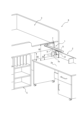
図1に示すように、本実施形態に係る照明器具1は、机2の上面に固定されている。また、本実施形態では、照明器具1、机2、机2を出納可能な下部空間Sを有するベッド3、箪笥4及び収納棚5により、システムベッド6が構成されている。システムベッド6は、机2、箪笥4及び収納棚5の配置が異なる種々のレイアウトで使用することができる。ベッド3は寝台3aと、寝台3aの下方に下部空間S形成するように寝台3aを床面に対して支持する支持部3bとを有している。支持部3bは一対の側壁3cで構成されているが、これに限らない。また、システムベッド6は箪笥4及び収納棚5を有しているが、これに限らない。例えば、システムベッド6は箪笥4及び収納棚5に代えて他の家具を有していてもよいし、箪笥4及び収納棚5を有していなくてもよい。なお、照明器具1はシステムベッド6以外の机の上面に固定して使用してもよい。
As shown in FIG. 1, a lighting fixture 1 according to this embodiment is fixed to the top surface of a
図2~図3に示すように、照明器具1は、机2の天板2aの上面に固定される下面7aを備える固定部7と、固定部7に連結するとともに灯具8を備えるアーム9とを有している。なお、固定部7は机2の天板2aの上面に固定されるものに限らず、例えば、机2に棚板を設け、当該棚板の上面に固定部7の下面7aを固定する構成としてもよい。
As shown in FIGS. 2 and 3, the lighting fixture 1 includes a
固定部7は、下面7aと対向する締付板7bと、締付板7bを下面7aに向けて移動させる操作部7cとを有するクランプ装置として構成されている。操作部7cは回転操作用の摘みで構成されているが、これに限らない。操作部7cを操作することで、下面7aと締付板7bの上面とで天板2aを挟み、それにより固定部7を天板2aに固定することができる。なお、固定部7はクランプ装置として構成されたものに限らず、例えばボルト、ナット等の締結具で机2に固定される構成であってもよい。
The
固定部7は、下面7aを有する固定部本体7dを有している。固定部本体7dは、固定部本体7dの上面に開口する挿入口7eを有している。挿入口7eにはアーム9の基端部9aが抜脱可能に挿入され、これによりアーム9が固定部7に連結される。つまり、アーム9の基端部9aは固定部7に着脱可能に連結される。したがって、アーム9を挿入口7eから抜脱した状態で固定部7を天板2aに取付ることができるので、天板2aへの固定部7の取付作業を容易に行うことができる。しかし、アーム9の基端部9aを固定部7に対して一体化した構成としてもよい。
The
また、アーム9の基端部9aは、挿入口7eに挿入された状態で下面7aに対して垂直な中心軸線Oを中心として回動可能である。したがって、アーム9の基端部9aを挿入口7eに挿入した状態で回動させることでアーム9全体の向きを調節できるので、アーム9の優れた可動範囲を実現することができる。なお、中心軸線Oは下面7aに対して垂直でなくてもよい。また、アーム9の基端部9aは、挿入口7eに挿入された状態で回動不能となるように構成されてもよい。
Further, the
このように、アーム9の基端部9aが固定部7に設けられた挿入口7eに抜脱可能且つ回転可能に挿入される構成とすることにより、後述する第1継手11aの高さH1(図4参照)を抑制しながら、上述した固定部7の優れた取付作業性とアーム9の優れた可動範囲との両方を実現することができる。
In this way, by configuring the
アーム9は、基端部9aを構成する第1リンク10aと、第1リンク10aに回動可能な第1継手11aを介して連結する第2リンク10bと、第2リンク10bに回動可能な第2継手11bを介して連結する第3リンク10cと、第3リンク10cに回動可能な第3継手11cを介して連結する第4リンク10dと、第4リンク10dに回動可能な第4継手11dを介して連結するとともに灯具8を備える第5リンク10eとを有している。このように、アーム9は5つのリンク10と4つの継手11とを有している。しかし、アーム9が少なくとも1つの回動可能な継手11を有している限り、リンク10と継手11の数は適宜増減が可能である。
The
第1継手11aは下面7aに対して平行な中心軸線X1を中心として回動可能である。第2継手11bは下面7aに対して平行な中心軸線X2を中心として回動可能である。第3継手11cは下面7aに対して平行な中心軸線X3を中心として回動可能である。第4継手11dは中心軸線X3に対して垂直な面内に位置する中心軸線X4を中心として回動可能である。なお、中心軸線X1~X4の向きは適宜変更が可能である。また、各継手11は1軸のみを中心に回動可能な構成に限らず、例えば、2軸のみを中心に回動可能に構成されてもよいし、3軸を中心に回動可能な自在継手として構成されてもよい。
The
灯具8は発光ダイオード(LED)などの光源を有しており、当該光源に電源コード12を介して電気を供給することで机2の天板2aの上面を照らすことができる。電源コード12は第1継手11aよりも灯具8に近い位置においてアーム9内に引き込まれている。つまり、電源コード12がアーム9の外部からアーム9内に向けて通過する通過部13(図4参照)が、第1継手11aよりも灯具8に近い位置に設けられている。したがって、第1継手11a内に電源コード12を配置する必要がないため、第1継手11aを小型化し、4つの継手11のうち最も固定部7に近い第1継手11aの高さH1(図4参照)を低くすることができる。なお、第1継手11aの高さH1とは、固定部7の下面7aからの高さを意味している。また、電源コード12をアーム9内に引き込む構成とすることで、照明器具1のみならず机2やシステムベッド6全体の美観を向上することができる。なお、電源コード12は、第1継手11aよりも灯具8に近い位置においてアーム9内に引き込まれる構成に限らない。例えば、第3継手11c周辺でアーム9内に引き込まれる構成としてもよい。また、照明器具1はアーム9から外部に向けて延びる電源コード12を有する構成に限らず、例えば乾電池等の内部電源を有する構成であってもよい。
The
第2リンク10bは灯具8をON/OFF操作するための操作パネル14を有している。操作パネル14は例えば、ON/OFF用ボタンと照度調整用ボタンを有している。操作パネル14は第2リンク10bの正面に設けられているが、これに限らず、例えば第2リンク10bの側面に設けてもよい。図4に示すように、電源コード12は第2リンク10bの背面の下部においてアーム9内に引き込まれている。したがって、電源コード12が灯具8を使用する際に邪魔にならず、また、美観をより一層向上することができる。なお、電源コード12は第2リンク10bのその他の部分においてアーム9内に引き込まれる構成であってもよい。
The
アーム9は中空構造となっており、操作パネル14のための回路及び配線を含む、灯具8のための回路及び配線がアーム9内に配置され、電源コード12に接続されている。
The
図2及び図4に示すように、アーム9は、4つの継手11のうち最も固定部7に近い第1継手11aの高さH1まで折畳み可能に構成されている。すなわち、アーム9は、図4に示すようにアーム9の高さH2が第1継手11aの高さH1となるまで折畳み可能である。換言すれば、アーム9は、図4に示すように第1継手11aがアーム9の最上部Tとなるまで、折畳み可能である。なお、アーム9の高さH2とは固定部7の下面7aからの高さを意味している。また、アーム9の最上部Tとは、固定部7の下面7aからの高さが最も高い部分である。アーム9の最上部Tは、各継手11の回動状況、つまりアーム9の姿勢によって変化する。例えば、図2に示す姿勢においてはアーム9の最上部Tは第2継手11bである。この姿勢から第2継手11bを回動させることにより、例えば第3継手11cが最上部Tとなる場合もある。
As shown in FIGS. 2 and 4, the
図2に示すように、第1継手11aの高さH1は、固定部7の下面7aが固定される机2の上面(つまり、天板2aの上面)からの下部空間Sの高さH3以下となっている。すなわち、H1≦H3である。したがって、アーム9を第1継手11aの高さH1まで、つまりH2=H1となるまで折畳むことにより、照明器具1を固定したままの状態で、図5に示すように机2をベッド3の下部空間Sに収納することができる。
As shown in FIG. 2, the height H1 of the first joint 11a is equal to or less than the height H3 of the lower space S from the upper surface of the
また、アーム9は、上面視においてアーム9が机2の天板2aの内側に収まり且つアーム9の高さH2が第1継手11aの高さH1となるように、折畳み可能である。より具体的には、第2継手11bを回動させて第3リンク10cを第2リンク10bの側に折返すことにより、アーム9を天板2aの内側に収めることができる。アーム9をこのように折畳むことにより、下部空間Sが収納棚5等の家具等を配置することで狭くなっている場合でも、机2を下部空間Sに収納することができる。
Further, the
前述した実施形態は本発明の実施形態の一例にすぎず、発明の要旨を逸脱しない範囲で種々変更可能であることはいうまでもない。 It goes without saying that the embodiment described above is only one example of the embodiment of the present invention, and that various changes can be made without departing from the gist of the invention.
1 照明器具
2 机
2a 天板
3 ベッド
3a 寝台
3b 支持部
3c 側壁
4 箪笥
5 収納棚
6 システムベッド
7 固定部
7a 下面
7b 締付板
7c 操作部
7d 固定部本体
7e 挿入口
8 灯具
9 アーム
9a アームの基端部
10 リンク
10a 第1リンク
10b 第2リンク
10c 第3リンク
10d 第4リンク
10e 第5リンク
11 継手
11a 第1継手
11b 第2継手
11c 第3継手
11d 第4継手
12 電源コード
13 通過部
14 操作パネル
S 下部空間
O 中心軸線
X1~X4 中心軸線
H1~H3 高さ
T 最上部
1
Claims (4)
机とを有し、
前記机は天板を有し、
前記照明器具は、前記机の上面に固定される下面を備える固定部と、前記固定部に連結する基端部、灯具及び少なくとも1つの継手を備えるアームとを有し、
前記アームは、前記基端部を構成する第1リンクと、前記第1リンクに回動可能な第1継手を介して連結する第2リンクと、前記第2リンクに回動可能な第2継手を介して連結する第3リンクとを有し、前記第2継手を回動させて前記第3リンクを前記第2リンクの側に折返すことにより、上面視において前記アームが前記机の前記天板の内側に収まり且つ前記少なくとも1つの継手のうち最も前記固定部に近い前記第1継手の高さまで折畳み可能である照明器具付き机。 lighting equipment and
has a desk,
The desk has a top plate,
The lighting fixture has a fixing part having a lower surface fixed to the top surface of the desk, a base end part connected to the fixing part, an arm including a lamp and at least one joint,
The arm includes a first link constituting the base end, a second link connected to the first link via a rotatable first joint, and a second rotatable joint to the second link. by rotating the second joint and folding the third link back toward the second link, the arm can be connected to the top of the desk in a top view. A desk with a lighting fixture that fits inside a plate and is foldable to the height of the first joint that is closest to the fixed part of the at least one joint.
前記電源コードは、前記第1継手よりも前記灯具に近い位置において前記アーム内に引き込まれている、請求項1に記載の照明器具付き机。 having a power cord that supplies electricity to the lamp;
The desk with a lighting device according to claim 1, wherein the power cord is drawn into the arm at a position closer to the lamp than the first joint.
机と、
前記机を出納可能な下部空間を有するベッドとを有し、
前記机は天板を有し、
前記照明器具は、前記机の上面に固定される下面を備える固定部と、前記固定部に連結する基端部、灯具及び少なくとも1つの継手を備えるアームとを有し、
前記アームは、前記基端部を構成する第1リンクと、前記第1リンクに回動可能な第1継手を介して連結する第2リンクと、前記第2リンクに回動可能な第2継手を介して連結する第3リンクとを有し、前記第2継手を回動させて前記第3リンクを前記第2リンクの側に折返すことにより、上面視において前記アームが前記机の前記天板の内側に収まり且つ前記少なくとも1つの継手のうち最も前記固定部に近い前記第1継手の高さまで折畳み可能であり、
前記第1継手の高さは、前記机の前記上面からの前記下部空間の高さ以下であるシステムベッド。 lighting equipment and
desk and
and a bed having a lower space capable of storing and retracting the desk,
The desk has a top plate,
The lighting fixture has a fixing part having a lower surface fixed to the top surface of the desk, a base end part connected to the fixing part, an arm including a lamp and at least one joint,
The arm includes a first link constituting the base end, a second link connected to the first link via a rotatable first joint, and a second rotatable joint to the second link. by rotating the second joint and folding the third link back toward the second link, the arm can be connected to the top of the desk in a top view. is foldable to the height of the first joint that fits inside the plate and is closest to the fixed part among the at least one joint;
The system bed wherein the height of the first joint is equal to or less than the height of the lower space from the upper surface of the desk.
Priority Applications (1)
| Application Number | Priority Date | Filing Date | Title |
|---|---|---|---|
| JP2019190424A JP7372811B2 (en) | 2019-10-17 | 2019-10-17 | Lighting equipment and system bed |
Applications Claiming Priority (1)
| Application Number | Priority Date | Filing Date | Title |
|---|---|---|---|
| JP2019190424A JP7372811B2 (en) | 2019-10-17 | 2019-10-17 | Lighting equipment and system bed |
Publications (2)
| Publication Number | Publication Date |
|---|---|
| JP2021068500A JP2021068500A (en) | 2021-04-30 |
| JP7372811B2 true JP7372811B2 (en) | 2023-11-01 |
Family
ID=75637482
Family Applications (1)
| Application Number | Title | Priority Date | Filing Date |
|---|---|---|---|
| JP2019190424A Active JP7372811B2 (en) | 2019-10-17 | 2019-10-17 | Lighting equipment and system bed |
Country Status (1)
| Country | Link |
|---|---|
| JP (1) | JP7372811B2 (en) |
Citations (3)
| Publication number | Priority date | Publication date | Assignee | Title |
|---|---|---|---|---|
| JP2002298640A (en) | 2001-03-28 | 2002-10-11 | Itoki Crebio Corp | Desk and illumination device used for the same |
| JP2008301976A (en) | 2007-06-06 | 2008-12-18 | Itoki Corp | Combination furniture of bed and desk |
| JP2010279619A (en) | 2009-06-05 | 2010-12-16 | Itoki Corp | Combination furniture of bed and desk |
Family Cites Families (2)
| Publication number | Priority date | Publication date | Assignee | Title |
|---|---|---|---|---|
| JPH01112603A (en) * | 1986-07-28 | 1989-05-01 | Matsushita Electric Works Ltd | Parallel crank type movable arm |
| KR20120002956U (en) * | 2010-10-21 | 2012-05-02 | 김영미 | Lighting Stands |
-
2019
- 2019-10-17 JP JP2019190424A patent/JP7372811B2/en active Active
Patent Citations (3)
| Publication number | Priority date | Publication date | Assignee | Title |
|---|---|---|---|---|
| JP2002298640A (en) | 2001-03-28 | 2002-10-11 | Itoki Crebio Corp | Desk and illumination device used for the same |
| JP2008301976A (en) | 2007-06-06 | 2008-12-18 | Itoki Corp | Combination furniture of bed and desk |
| JP2010279619A (en) | 2009-06-05 | 2010-12-16 | Itoki Corp | Combination furniture of bed and desk |
Also Published As
| Publication number | Publication date |
|---|---|
| JP2021068500A (en) | 2021-04-30 |
Similar Documents
| Publication | Publication Date | Title |
|---|---|---|
| US9316384B2 (en) | Collapsible worklight assembly | |
| US11051611B2 (en) | Desk system | |
| JP6273295B2 (en) | Pedal board support for electrical equipment | |
| CN102840452B (en) | Box-type lamp | |
| CA3129363A1 (en) | Tripod system | |
| WO2021008344A1 (en) | Support base, fan and lamp | |
| JP6827703B2 (en) | Top plate elevating furniture | |
| JP6838716B2 (en) | Top plate elevating desk | |
| JP7372811B2 (en) | Lighting equipment and system bed | |
| US20220186914A1 (en) | Three-section hingedly connected lighting panel | |
| US20240043172A1 (en) | Storage box light | |
| JP2009087766A (en) | Stand type lighting fixture | |
| JP7215074B2 (en) | table | |
| KR200452437Y1 (en) | Reading desk which is established on a supporter | |
| JP2009087765A (en) | Stand type lighting fixture | |
| KR20140000882U (en) | A Desk Lamp | |
| JP7151374B2 (en) | table | |
| JP4226809B2 (en) | lighting equipment | |
| JP2005116197A (en) | Lighting system and display rack device | |
| KR200325083Y1 (en) | Lamp for both Desk and Indoor Room | |
| JP7286944B2 (en) | table | |
| JP2009087764A (en) | Stand type lighting fixture | |
| JP2008301976A (en) | Combination furniture of bed and desk | |
| JP3837222B2 (en) | Wiring furniture | |
| JP7215073B2 (en) | table |
Legal Events
| Date | Code | Title | Description |
|---|---|---|---|
| A621 | Written request for application examination |
Free format text: JAPANESE INTERMEDIATE CODE: A621 Effective date: 20220831 |
|
| A131 | Notification of reasons for refusal |
Free format text: JAPANESE INTERMEDIATE CODE: A131 Effective date: 20230523 |
|
| A977 | Report on retrieval |
Free format text: JAPANESE INTERMEDIATE CODE: A971007 Effective date: 20230524 |
|
| A521 | Request for written amendment filed |
Free format text: JAPANESE INTERMEDIATE CODE: A523 Effective date: 20230705 |
|
| TRDD | Decision of grant or rejection written | ||
| A01 | Written decision to grant a patent or to grant a registration (utility model) |
Free format text: JAPANESE INTERMEDIATE CODE: A01 Effective date: 20231017 |
|
| A61 | First payment of annual fees (during grant procedure) |
Free format text: JAPANESE INTERMEDIATE CODE: A61 Effective date: 20231020 |
|
| R150 | Certificate of patent or registration of utility model |
Ref document number: 7372811 Country of ref document: JP Free format text: JAPANESE INTERMEDIATE CODE: R150 |