JP7371602B2 - Antenna module and antenna driving method - Google Patents
Antenna module and antenna driving method Download PDFInfo
- Publication number
- JP7371602B2 JP7371602B2 JP2020173357A JP2020173357A JP7371602B2 JP 7371602 B2 JP7371602 B2 JP 7371602B2 JP 2020173357 A JP2020173357 A JP 2020173357A JP 2020173357 A JP2020173357 A JP 2020173357A JP 7371602 B2 JP7371602 B2 JP 7371602B2
- Authority
- JP
- Japan
- Prior art keywords
- circularly polarized
- polarized antenna
- antenna elements
- antenna
- module according
- Prior art date
- Legal status (The legal status is an assumption and is not a legal conclusion. Google has not performed a legal analysis and makes no representation as to the accuracy of the status listed.)
- Active
Links
- 238000000034 method Methods 0.000 title claims description 10
- 230000010287 polarization Effects 0.000 claims description 15
- 238000003491 array Methods 0.000 claims description 9
- 239000000203 mixture Substances 0.000 claims 1
- 230000005540 biological transmission Effects 0.000 description 34
- 238000010586 diagram Methods 0.000 description 22
- 238000004088 simulation Methods 0.000 description 17
- 230000000694 effects Effects 0.000 description 16
- 230000000052 comparative effect Effects 0.000 description 13
- 230000004048 modification Effects 0.000 description 11
- 238000012986 modification Methods 0.000 description 11
- 238000005388 cross polarization Methods 0.000 description 6
- 239000000758 substrate Substances 0.000 description 5
- 230000005284 excitation Effects 0.000 description 3
- 230000003321 amplification Effects 0.000 description 2
- 230000007423 decrease Effects 0.000 description 2
- 238000003199 nucleic acid amplification method Methods 0.000 description 2
- 230000005855 radiation Effects 0.000 description 2
- 239000011159 matrix material Substances 0.000 description 1
Images


Classifications
-
- H—ELECTRICITY
- H01—ELECTRIC ELEMENTS
- H01Q—ANTENNAS, i.e. RADIO AERIALS
- H01Q21/00—Antenna arrays or systems
- H01Q21/24—Combinations of antenna units polarised in different directions for transmitting or receiving circularly and elliptically polarised waves or waves linearly polarised in any direction
-
- H—ELECTRICITY
- H01—ELECTRIC ELEMENTS
- H01Q—ANTENNAS, i.e. RADIO AERIALS
- H01Q21/00—Antenna arrays or systems
- H01Q21/0006—Particular feeding systems
-
- H—ELECTRICITY
- H01—ELECTRIC ELEMENTS
- H01Q—ANTENNAS, i.e. RADIO AERIALS
- H01Q21/00—Antenna arrays or systems
- H01Q21/06—Arrays of individually energised antenna units similarly polarised and spaced apart
- H01Q21/061—Two dimensional planar arrays
- H01Q21/065—Patch antenna array
-
- H—ELECTRICITY
- H01—ELECTRIC ELEMENTS
- H01Q—ANTENNAS, i.e. RADIO AERIALS
- H01Q23/00—Antennas with active circuits or circuit elements integrated within them or attached to them
-
- H—ELECTRICITY
- H01—ELECTRIC ELEMENTS
- H01Q—ANTENNAS, i.e. RADIO AERIALS
- H01Q9/00—Electrically-short antennas having dimensions not more than twice the operating wavelength and consisting of conductive active radiating elements
- H01Q9/04—Resonant antennas
- H01Q9/0407—Substantially flat resonant element parallel to ground plane, e.g. patch antenna
- H01Q9/0428—Substantially flat resonant element parallel to ground plane, e.g. patch antenna radiating a circular polarised wave
Description
本発明は、アンテナモジュール及びアンテナ駆動方法に関する。 The present invention relates to an antenna module and an antenna driving method.
円偏波の軸比を改善することができるアンテナとして、複数の円偏波アンテナ素子を備えたシーケンシャルアレーアンテナが知られている(例えば、下記の特許文献1参照。)。シーケンシャルアレーアンテナは、主放射方向を回転軸として任意の角度回転させた姿勢で配置された複数の円偏波アンテナ素子を含んでおり、各円偏波アンテナ素子は、回転角に応じた位相差を付けて励振される。
As an antenna capable of improving the axial ratio of circularly polarized waves, a sequential array antenna including a plurality of circularly polarized antenna elements is known (see, for example,
下記の特許文献1に開示されたシーケンシャルアレーアンテナは、複数のシーケンシャルサブアレーで構成されており、シーケンシャルサブアレーの各々が複数の円偏波アンテナ素子を含んでいる。1つのシーケンシャルサブアレーに含まれる複数の円偏波アンテナ素子がシーケンシャル化されており、複数のシーケンシャルサブアレーがさらにシーケンシャル化されている。一例として、1つのシーケンシャルサブアレーに着目すると、4個の円偏波アンテナ素子の基準軸を順番に45°ずつ回転させている。このような構成を採用することにより、個々の円偏波アンテナ素子の特性にばらつきがある場合や、励振位相または振幅に誤差がある場合にも、良好な軸比を得ることができる。
The sequential array antenna disclosed in
通信距離や通信速度(ビットレート)によって、すべての円偏波アンテナ素子を動作させる必要がない場合がある。一部の円偏波アンテナ素子を動作せる場合にも、良好な軸比を維持し、かつ消費電力を低減させることが望まれる。本発明の目的は、複数の円偏波アンテナ素子の一部を動作させる場合に、良好な軸比を維持し、かつ消費電力を低減させることが可能なアンテナモジュール及びアンテナ駆動方法を提供することである。 Depending on the communication distance and communication speed (bit rate), it may not be necessary to operate all circularly polarized antenna elements. Even when operating some circularly polarized antenna elements, it is desirable to maintain a good axial ratio and reduce power consumption. An object of the present invention is to provide an antenna module and an antenna driving method that can maintain a good axial ratio and reduce power consumption when operating some of a plurality of circularly polarized antenna elements. It is.
本発明の一観点によると、
それぞれが1つの入出力ポートと複数のアンテナポートとを持ち高周波信号の増幅を行う複数のセグメントと、
それぞれが複数の円偏波アンテナ素子を含む複数のサブアレーアンテナと
を備え、
前記複数の円偏波アンテナ素子は、それぞれ前記複数のアンテナポートのいずれかに接続されており、
前記複数のサブアレーアンテナの各々に含まれる前記複数の円偏波アンテナ素子は、サブアレーアンテナごとにシーケンシャルアレーを構成しており、
前記複数のセグメントの各々は、
第1ポートに入力された信号を前記複数のアンテナポートに分配し、前記複数のアンテナポートのそれぞれに入力された信号を合成して前記第1ポートから出力する分配合成器と、
前記複数のアンテナポートのそれぞれと前記分配合成器との間に接続された移相器と、
前記入出力ポートと前記第1ポートとの間に接続された第1増幅器と
を含み、
前記複数のサブアレーアンテナのいずれの一つのサブアレーアンテナにおいても、一つのサブアレーアンテナに含まれる前記複数の円偏波アンテナ素子がそれぞれ接続された前記複数のアンテナポートは、一つのセグメントに含まれており、
前記複数の円偏波アンテナ素子の各々は、2つの給電点を有しており、
前記複数のアンテナポートの各々は、ハイブリッド回路を介して円偏波アンテナ素子の2つの給電点に接続されており、前記複数の円偏波アンテナ素子は、放射される円偏波の旋回方向が前記複数のサブアレーアンテナにわたって同一になるように、前記ハイブリッド回路によって励振されるアンテナモジュールが提供される。
According to one aspect of the invention:
a plurality of segments each having one input/output port and a plurality of antenna ports and amplifying high frequency signals;
a plurality of subarray antennas each including a plurality of circularly polarized antenna elements;
Each of the plurality of circularly polarized antenna elements is connected to one of the plurality of antenna ports,
The plurality of circularly polarized antenna elements included in each of the plurality of subarray antennas constitute a sequential array for each subarray antenna,
Each of the plurality of segments is
a distribution/synthesizer that distributes a signal input to a first port to the plurality of antenna ports, combines the signals input to each of the plurality of antenna ports, and outputs the result from the first port;
a phase shifter connected between each of the plurality of antenna ports and the distribution/combiner;
a first amplifier connected between the input/output port and the first port;
In any one of the plurality of subarray antennas, the plurality of antenna ports to which the plurality of circularly polarized antenna elements included in one subarray antenna are respectively connected are included in one segment. ,
Each of the plurality of circularly polarized antenna elements has two feeding points,
Each of the plurality of antenna ports is connected to two feed points of a circularly polarized antenna element via a hybrid circuit, and the plurality of circularly polarized antenna elements are configured such that the rotation direction of the circularly polarized wave to be radiated is An antenna module is provided that is excited by the hybrid circuit so as to be identical across the plurality of sub-array antennas .
本発明の他の観点によると、
複数の第1増幅器でM個の円偏波アンテナ素子を動作させる構成を持つアンテナモジュールにおいて、M個よりも少ないm個の円偏波アンテナ素子を選択して動作させるアンテナ駆動方法であって、
前記複数の第1増幅器のいずれの1つも、前記M個の円偏波アンテナ素子のうち複数の円偏波アンテナ素子を動作させるように構成されており、
前記M個の円偏波アンテナ素子は、複数のシーケンシャルアレーを構成しており、
選択されるm個の円偏波アンテナ素子が1つまたは複数のシーケンシャルアレーを構成する条件と、m個の円偏波アンテナ素子を動作させるのに必要な前記第1増幅器の個数が最も少なくなる条件とを満たすように、前記M個の円偏波アンテナ素子からm個の円偏波アンテナ素子を選択し、選択したm個の円偏波アンテナ素子を動作させるアンテナ駆動方法が提供される。
According to another aspect of the invention:
In an antenna module having a configuration in which M circularly polarized antenna elements are operated by a plurality of first amplifiers, an antenna driving method that selects and operates fewer than M circularly polarized antenna elements, the method comprising:
Any one of the plurality of first amplifiers is configured to operate a plurality of circularly polarized antenna elements among the M circularly polarized antenna elements,
The M circularly polarized antenna elements constitute a plurality of sequential arrays,
The conditions that the selected m circularly polarized antenna elements constitute one or more sequential arrays and the number of the first amplifiers required to operate the m circularly polarized antenna elements are minimized. An antenna driving method is provided in which m circularly polarized antenna elements are selected from the M circularly polarized antenna elements and the selected m circularly polarized antenna elements are operated so as to satisfy the conditions.
1つのサブアレーアンテナのすべての円偏波アンテナ素子を動作させるためには、1つのセグメントを動作させればよい。1つのサブアレーアンテナのすべての円偏波アンテナ素子によってシーケンシャルアレーが構成されているため、1つのセグメントを動作させる場合でも、良好な軸比を維持することができる。また、それぞれがシーケンシャルアレーを構成する複数のサブアレーアンテナのうち一部のサブアレーアンテナのみを動作させるために必要とされるセグメントの個数は、動作させるサブアレーアンテナの個数以下である。動作させるサブアレーアンテナの個数より多いセグメントを動作させる必要がないため、消費電力を低減させることが可能である。 In order to operate all the circularly polarized antenna elements of one sub-array antenna, it is sufficient to operate one segment. Since all the circularly polarized antenna elements of one sub-array antenna constitute a sequential array, a good axial ratio can be maintained even when one segment is operated. Furthermore, the number of segments required to operate only some of the plurality of subarray antennas, each of which constitutes a sequential array, is less than or equal to the number of subarray antennas to be operated. Since there is no need to operate more segments than the number of sub-array antennas to be operated, power consumption can be reduced.
[第1実施例]
図1から図3までの図面を参照して、第1実施例によるアンテナモジュールについて説明する。
[First example]
An antenna module according to a first embodiment will be described with reference to the drawings from FIG. 1 to FIG. 3.
図1は第1実施例によるアンテナモジュールのブロック図である。第1実施例によるアンテナモジュールは、高周波信号の電力増幅を行う複数のセグメント20と、複数のセグメント20のそれぞれに対応して配置されたサブアレーアンテナ50と、複数の伝送線路60とを備えている。複数のセグメント20のそれぞれは、1つの入出力ポート21と、複数のアンテナポート22とを含む。セグメント20の構成については、後に図2を参照して説明する。
FIG. 1 is a block diagram of an antenna module according to a first embodiment. The antenna module according to the first embodiment includes a plurality of
複数のサブアレーアンテナ50の各々は、複数の円偏波アンテナ素子51を含む。複数のサブアレーアンテナ50の各々に含まれる複数の円偏波アンテナ素子51は、サブアレーアンテナ50ごとにシーケンシャルアレーを構成している。サブアレーアンテナ50に含まれる円偏波アンテナ素子51の個数は、対応するセグメント20のアンテナポート22の個数と等しい。セグメント20のアンテナポート22が、それぞれ対応するサブアレーアンテナ50の円偏波アンテナ素子51に、伝送線路60によって接続されている。
Each of the plurality of
1つの信号ポート80から入力された高周波信号が、分配合成器81によって複数のセグメント20のそれぞれの入出力ポート21に分配される。セグメント20の各々は、入出力ポート21に入力された高周波信号の電力増幅を行い、かつ位相調整を行って複数のアンテナポート22から出力する。
A high frequency signal input from one
複数の円偏波アンテナ素子51で受信された受信信号が、それぞれ複数のアンテナポート22からセグメント20に入力される。セグメント20は、複数のアンテナポート22のそれぞれに入力された受信信号を増幅し位相調整を行った後に合成して入出力ポート21から出力する。
Received signals received by the plurality of circularly
複数のセグメント20のそれぞれの入出力ポート21から出力された受信信号が、分配合成器81によって合成され、信号ポート80から出力される。
Received signals output from the respective input/
図2は、1つのセグメント20(図1)のブロック図である。分配合成器27が、1つの第1ポート27Aと複数の第2ポート27Bとを有する。分配合成器27は第1ポート27Aに入力された信号を複数の第2ポート27Bに分配して出力する。さらに、複数の第2ポート27Bのそれぞれに入力された信号を合成して第1ポート27Aから出力する。
FIG. 2 is a block diagram of one segment 20 (FIG. 1). The
入出力ポート21と分配合成器27の第1ポート27Aとの間に、送受信切替スイッチ23、第1増幅器24及び送受信切替スイッチ26が接続されている。第1増幅器24は、第1パワーアンプ24Pと第1ローノイズアンプ24Lとを含む。送受信切替スイッチ23、26が送信状態のとき、入出力ポート21から入力された高周波信号が、第1パワーアンプ24Pで増幅されて、分配合成器27の第1ポート27Aに入力される。送受信切替スイッチ23、26が受信状態のとき、分配合成器27の第1ポート27Aから出力された受信信号が第1ローノイズアンプ24Lで増幅されて入出力ポート21から出力される。
A transmission/
分配合成器27の複数の第2ポート27Bと複数のアンテナポート22とのそれぞれの間に、移相器28、可変減衰器29、送受信切替スイッチ30、第2増幅器31、及び送受信切替スイッチ33が接続されている。第2増幅器31は、第2パワーアンプ31P及び第2ローノイズアンプ31Lを含む。
A
送受信切替スイッチ30、33が送信状態の時、分配合成器27の第2ポート27Bから出力された高周波信号が、移相器28、可変減衰器29、及び第2パワーアンプ31Pを通ってアンテナポート22から出力される。送受信切替スイッチ30、33が受信状態の時、アンテナポート22から入力された受信信号が、第2ローノイズアンプ31L、可変減衰器29、及び移相器28を通って分配合成器27の第2ポート27Bに入力される。
When the transmission/reception changeover switches 30 and 33 are in the transmission state, the high frequency signal output from the
移相器28は、制御回路35からの制御により、信号の位相を調整する。可変減衰器29は、制御回路35からの制御により、信号の減衰量を調整する。第2パワーアンプ31Pは、高周波信号の電力増幅を行う。第2ローノイズアンプ31Lは、受信信号を増幅する。
The
図3は、1つのサブアレーアンテナ50(図1)に含まれシーケンシャルアレーを構成する複数の円偏波アンテナ素子51の平面図である。複数の円偏波アンテナ素子51は、平面視において円形の形状を有しており、2つの給電点52から給電される。2つの給電点52は、直交する2本の半径上に配置されている。2つの給電点52に90°の位相差を持つ高周波信号を供給することにより、円偏波が放射される。2つの給電点52に供給する2つの高周波信号の位相の進みまたは遅れによって、放射される円偏波の旋回方向(右旋または左旋)が決定される。円偏波アンテナ素子51の幾何中心から、2つの給電点52を両端とする線分の中点を向く方向を基準方向53ということとする。
FIG. 3 is a plan view of a plurality of circularly
シーケンシャルアレーを構成するN個の円偏波アンテナ素子51に順番に0からN-1まで通し番号を付したとき、i番目の円偏波アンテナ素子51の基準方向53は、0番目の円偏波アンテナ素子51の基準方向53に対して回転角α=(i×360/N)°だけ時計回りに回転した姿勢を有する。例えば、3個の円偏波アンテナ素子51が1つのシーケンシャルアレーを構成している場合は、0番目の円偏波アンテナ素子51の基準方向53に対して他の2つの円偏波アンテナ素子51の基準方向53は、それぞれ120°及び240°回転している。4個の円偏波アンテナ素子51が1つのシーケンシャルアレーを構成している場合は、0番目の円偏波アンテナ素子51の基準方向53に対して他の3つの円偏波アンテナ素子51の基準方向53は、それぞれ90°、180°、及び270°回転している。
When N circularly
ただし、例外として、シーケンシャルアレーを2個の円偏波アンテナ素子51で構成する場合には、回転角αを90°にすることが好ましい。
However, as an exception, when the sequential array is configured with two circularly
次に、第1実施例の優れた効果について説明する。
第1実施例によるアンテナモジュールにおいて、通信距離や通信レートによってはすべての円偏波アンテナ素子51を動作させる必要がない場合がある。例えば、通信距離が短い場合や、通信レートが遅い場合は、一部の円偏波アンテナ素子51のみを動作させても十分なゲインが確保される場合がある。
Next, the excellent effects of the first embodiment will be explained.
In the antenna module according to the first embodiment, depending on the communication distance and communication rate, it may not be necessary to operate all the circularly
シーケンシャルアレーを構成する複数の円偏波アンテナ素子51は、すべての円偏波アンテナ素子51を動作させた場合に、軸比を改善する効果が最も高くなる。一部の円偏波アンテナ素子51のみを動作させた場合には、軸比を改善する十分な効果が得られない場合がある。第1実施例では、複数のセグメント20のうち1つのセグメント20のみを動作させる場合でも、1つのシーケンシャルアレーを構成するすべての円偏波アンテナ素子51が動作する。このため、軸比を改善する十分な効果を得ることができる。
The plurality of circularly
1つのシーケンシャルアレーを構成する複数の円偏波アンテナ素子51が複数のセグメント20に跨って接続されている場合に、1つのシーケンシャルアレーを構成する複数の円偏波アンテナ素子51のすべてを動作させるには、複数のセグメント20を動作させなければならない。例えば、円偏波アンテナ素子51の個数分の第2増幅器31(図2)と、複数の第1増幅器24を動作させなければならない。これに対して第1実施例では、1つのシーケンシャルアレーを構成するすべての円偏波アンテナ素子51を動作させるためには、円偏波アンテナ素子51の個数分の第2増幅器31(図2)と、1つの第1増幅器24のみを動作させればよい。このため、低消費電力動作が可能である。
When the plurality of circularly
次に、第1実施例の変形例について説明する。
第1実施例によるアンテナモジュールは、送信機能及び受信機能の両方を備えているが、送信機能のみ、または受信機能のみを備えたアンテナモジュールを構成してもよい。この場合には、送受信切替スイッチ23、26、30、33は不要である。また、第1増幅器24は、第1パワーアンプ24P及び第1ローノイズアンプ24Lの一方を備えればよい。同様に、第2増幅器31は、第2パワーアンプ31P及び第2ローノイズアンプ31Lの一方を備えればよい。
Next, a modification of the first embodiment will be described.
Although the antenna module according to the first embodiment has both a transmitting function and a receiving function, an antenna module having only a transmitting function or only a receiving function may be configured. In this case, the transmission/reception changeover switches 23, 26, 30, and 33 are unnecessary. Further, the
第1実施例では、複数のセグメント20と複数のサブアレーアンテナ50とが1対1に対応している。その他の構成として、1つのセグメント20に複数のサブアレーアンテナ50を対応させてもよい。すなわち、複数のサブアレーアンテナ50のいずれの一つのサブアレーアンテナ50においても、一つのサブアレーアンテナ50に含まれる複数の円偏波アンテナ素子51がそれぞれ接続された複数のアンテナポート22が、一つのセグメント20に含まれるようにすればよい。
In the first embodiment, the plurality of
[第2実施例]
次に、図4から図10までの図面を参照して第2実施例によるアンテナモジュールについて説明する。以下、第1実施例によるアンテナモジュール(図1、図2、図3)と共通の構成については説明を省略する。
[Second example]
Next, an antenna module according to a second embodiment will be described with reference to the drawings from FIG. 4 to FIG. 10. Hereinafter, description of the common configurations with the antenna module according to the first embodiment (FIGS. 1, 2, and 3) will be omitted.
図4は第2実施例によるアンテナモジュールのブロック図である。第1実施例では、1つのセグメント20のアンテナポート22の個数と、そのセグメント20に対応するサブアレーアンテナ50を構成する円偏波アンテナ素子51の個数とが等しい。これに対して第2実施例では、セグメント20とサブアレーアンテナ50との組み合わせの中に、円偏波アンテナ素子51の個数がアンテナポート22の個数より少ないものが存在する。例えば、アンテナポート22の個数が4個であり、それに対応するサブアレーアンテナ50の円偏波アンテナ素子51の個数が3個の組み合わせが存在する。
FIG. 4 is a block diagram of an antenna module according to a second embodiment. In the first embodiment, the number of
図5Aは、30個の円偏波アンテナ素子51の平面的な配置の一例を示す模式図である。基板55に、30個の円偏波アンテナ素子51が6行5列の行列状に配置されている。30個の円偏波アンテナ素子51に、8個のセグメント20から給電される。8個のセグメント20は、それぞれ4個のアンテナポート22を有している。すなわち、合計で32個のアンテナポート22が設けられている。8個のセグメント20に通し番号を付し、32個のアンテナポート22にも通し番号を付す。セグメント20に付された通し番号を「S」付きの数字で表し、アンテナポート22に付された通し番号を「#」付きの数字で表す。8個のセグメント20に、S0からS7までの通し番号が付され、32個のアンテナポート22に#0から#31までの通し番号が付される。j番目のセグメント20の4個のアンテナポート22に付す通し番号を、それぞれ4j、4j+1、4j+2、4j+3とする。
FIG. 5A is a schematic diagram showing an example of a planar arrangement of 30 circularly polarized
複数の円偏波アンテナ素子51のうち同一のセグメント20に接続されているものを破線で取り囲み、破線内にハッチングを付すとともに、対応するセグメント20の通し番号を「S」付きの数字で表示している。さらに、円偏波アンテナ素子51のそれぞれに、接続されているアンテナポート22の通り番号を、「#」付きの数字で表示している。
Among the plurality of circularly
通し番号がS1及びS2のセグメント20には、それぞれ3個の円偏波アンテナ素子51が接続されている。すなわち、通し番号がS1及びS2のセグメント20のそれぞれの4個のアンテナポート22のうち1つのアンテナポート22には、円偏波アンテナ素子51が接続されていない。より具体的には、通し番号が#7及び#8のアンテナポート22には、円偏波アンテナ素子51が接続されていない。その他のセグメント20のそれぞれについては、4個のアンテナポート22にそれぞれ円偏波アンテナ素子51が接続されている。
Three circularly
図5Bは、第2実施例によるアンテナモジュールにおける円偏波アンテナ素子51の各々の回転角α(図3)を示す図である。第2実施例では、1つのセグメント20に接続されるサブアレーアンテナ50の複数の円偏波アンテナ素子51がシーケンシャルアレーを構成している。このため、通し番号がS0、S3、S4、S5、S6、及びS7のそれぞれのセグメント20に接続されている4個の円偏波アンテナ素子51のそれぞれの回転角αは、0°、90°、180°、及び270°である。通し番号がS1及びS2のセグメント20のそれぞれに接続されている3個の円偏波アンテナ素子51のそれぞれの回転角αは、0°、120°、及び240°である。
FIG. 5B is a diagram showing the rotation angle α (FIG. 3) of each circularly polarized
図5Cは、比較例によるアンテナモジュールにおける円偏波アンテナ素子51の各々の回転角α(図3)を示す図である。30個の円偏波アンテナ素子51が、全体としてシーケンシャルアレーを構成するように円偏波アンテナ素子51の各々の回転角αが設定されている。具体的には、左下の領域に配置されている8個の円偏波アンテナ素子51の回転角αを0°に設定し、左上の領域に配置されている7個の円偏波アンテナ素子51の回転角αを90°に設定し、右下の領域に配置されている7個の円偏波アンテナ素子51の回転角αを180°に設定し、右上の領域に配置されている8個の円偏波アンテナ素子51の回転角αを270°に設定している。
FIG. 5C is a diagram showing the rotation angle α (FIG. 3) of each circularly polarized
比較例では、30個の円偏波アンテナ素子51が全体としてシーケンシャルアレーを構成しているが、セグメント20のそれぞれに接続されている3個または4個の円偏波アンテナ素子51がシーケンシャルアレーを構成しているわけではない。例えば、通し番号がS0のセグメント20に接続されている4個の円偏波アンテナ素子51の回転角αは、すべて0°であり、通し番号がS1のセグメント20に接続されている3個の円偏波アンテナ素子51の各々の回転角αは、0°、180°、および180°である。
In the comparative example, 30 circularly polarized
次に、第2実施例の優れた効果について説明する。
第2実施例の優れた効果を確認するために、第2実施例によるアンテナモジュール(図5B)及び比較例によるアンテナモジュール(図5C)について、ゲイン及び軸比のシミュレーションを行った。図6から図10までの図面を参照して、このシミュレーション結果について説明する。
Next, the excellent effects of the second embodiment will be explained.
In order to confirm the excellent effects of the second example, simulations of gain and axial ratio were performed for the antenna module according to the second example (FIG. 5B) and the antenna module according to the comparative example (FIG. 5C). The simulation results will be explained with reference to the drawings from FIG. 6 to FIG. 10.
図6は、30個の円偏波アンテナ素子51が配置された基板55に対する座標系を示す斜視図である。6行5列に配置された30個の円偏波アンテナ素子51の中心を原点とし、基板55の法線方向(複数の円偏波アンテナ素子51の正面方向)をx軸の正の方向とする。6行5列に配置された30個の円偏波アンテナ素子51の行方向をy軸方向、列方向をz軸方向とする。
FIG. 6 is a perspective view showing a coordinate system for a
z軸の正方向を基準とする極角をθと表記し、x軸の正方向からの方位角をφと表記する。zx面及びxy面における放射パターンをシミュレーションにより求めた。複数の円偏波アンテナ素子51の励振周波数は、無線通信規格であるIEEE802.11ayのチャンネル1からチャンネル4までの各チャンネルの中心周波数とした。チャンネル1からチャンネル4までの4つのチャンネルの中心周波数は、それぞれ58.32GHz、60.48GHz、62.64GHz、及び64.8GHzである。
The polar angle with respect to the positive direction of the z-axis is expressed as θ, and the azimuth angle from the positive direction of the x-axis is expressed as φ. Radiation patterns in the zx plane and the xy plane were determined by simulation. The excitation frequency of the plurality of circularly
30個の円偏波アンテナ素子51は、右旋円偏波を放射するように設計されているが、一般的に若干の左旋円偏波成分を含む。すなわち、円偏波アンテナ素子51の各々から放射される円偏波の軸比は0dBより大きい。また、x軸の正の方向(θ=90°、φ=0°)で右旋円偏波がメインビームを形成するように、複数の円偏波アンテナ素子51の励振位相を調整した。
The 30 circularly polarized
すべてのセグメント20(図5A)を動作させた場合、通し番号がS0からS3までの4個のセグメント20を動作させた場合、及び通し番号がS0及びS1の2個セグメント20を動作させた場合について、シミュレーションを行った。すべてのセグメント20を動作させると、30個すべての円偏波アンテナ素子51が動作する。通し番号がS0からS3までの4個のセグメント20を動作させると、通し番号が#0から#15までの14個の円偏波アンテナ素子51が動作する。通し番号がS0及びS1の2つのセグメント20を動作させると、通し番号が#0から#6までの7個の円偏波アンテナ素子51が動作する。
When all segments 20 (FIG. 5A) are operated, when four
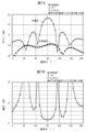
図7Aは、第2実施例によるアンテナモジュール(図5B)のすべての円偏波アンテナ素子51を、チャンネル1の中心周波数(58.32GHz)で動作させた場合の、zx断面(φ=0°)におけるゲインと極角θとの関係を示すグラフである。横軸は極角θを単位「°」で表し、縦軸はゲインを単位「dBi」で表す。グラフ中の中空の丸記号が主偏波(右旋円偏波)のゲインを示し、黒く塗りつぶした丸記号が交差偏波(左旋円偏波)のゲインを示している。極角θ=90°の方向(正面方向)に主偏波のメインビームが形成されている。
FIG. 7A shows a zx cross section (φ=0°) when all circularly
図7Bは、図7Aに示したシミュレーション結果から求めた軸比を示すグラフである。正面方向で軸比が最も小さくなっていることがわかる。 FIG. 7B is a graph showing the axial ratio obtained from the simulation results shown in FIG. 7A. It can be seen that the axial ratio is smallest in the front direction.
図8Aは、第2実施例によるアンテナモジュール(図5B)のすべての円偏波アンテナ素子51を、チャンネル1の中心周波数(58.32GHz)で動作させた場合の、xy断面(θ=90°)におけるゲインと方位角φとの関係を示すグラフである。横軸は方位角φを単位「°」で表し、縦軸はゲインを単位「dBi」で表す。グラフ中の中空の丸記号が主偏波(右旋円偏波)のゲインを示し、黒く塗りつぶした丸記号が交差偏波(左旋円偏波)のゲインを示している。方位角φ=0°の方向(正面方向)に主偏波のメインビームが形成されている。
FIG. 8A shows an xy cross section (θ=90°) when all circularly
図8Bは、図8Aに示したシミュレーション結果から求めた軸比を示すグラフである。正面方向で軸比が最も小さくなっていることがわかる。 FIG. 8B is a graph showing the axial ratio obtained from the simulation results shown in FIG. 8A. It can be seen that the axial ratio is smallest in the front direction.
第2実施例によるアンテナモジュール(図5B)及び比較例によるアンテナモジュール(図5C)について、動作させるセグメント20の個数及びチャンネルが異なる複数の条件についても同様のシミュレーションを行い、主偏波及び交差偏波のゲイン、及び軸比を求めた。
Similar simulations were performed for the antenna module according to the second example (FIG. 5B) and the antenna module according to the comparative example (FIG. 5C) under a plurality of conditions in which the number of
図9A及び図9Bは、それぞれチャンネルごとに主偏波ゲイン及び交差偏波ゲインを示すグラフである。図9A及び図9Bにおいて、丸記号付き実線は、第2実施例によるアンテナモジュール(図5B)のシミュレーション結果を示し、三角記号付き破線は、比較例によるアンテナモジュール(図5C)のシミュレーション結果を示している。また、実線及び破線の太さは、動作させたセグメント20の個数に対応している。最も太い実線及び破線は、すべてのセグメント20を動作させた場合のシミュレーション結果を示している。2番目に太い実線及び破線は、通し番号がS0からS3までの4個のセグメント20を動作させた場合のシミュレーション結果を示している。最も細い実線及び破線は、通し番号がS0及びS1の2個のセグメント20を動作させた場合のシミュレーション結果を示している。
9A and 9B are graphs showing main polarization gain and cross polarization gain for each channel, respectively. 9A and 9B, a solid line with a circle symbol indicates the simulation result of the antenna module according to the second example (FIG. 5B), and a broken line with a triangle symbol indicates the simulation result of the antenna module according to the comparative example (FIG. 5C). ing. Moreover, the thickness of the solid line and the broken line correspond to the number of
動作させるセグメント20の個数(すなわち、動作させる円偏波アンテナ素子51の個数)が少なくなると、主偏波ゲインが低下している。ただし、主偏波のゲイン(図9A)は、第2実施例によるアンテナモジュール(図5B)と比較例によるアンテナモジュール(図5C)とで大きな差はなく、チャンネル間の差も小さい。
As the number of
ところが、交差偏波ゲイン(図9B)は、第2実施例によるアンテナモジュール(図5B)と比較例によるアンテナモジュール(図5C)とで大きな差が生じている。特に、比較例の場合は、チャンネル4の交差偏波ゲインが、他のチャンネルに比べて大きくなっている。
However, there is a large difference in cross-polarization gain (FIG. 9B) between the antenna module according to the second example (FIG. 5B) and the antenna module according to the comparative example (FIG. 5C). In particular, in the case of the comparative example, the cross-polarization gain of
図10は、図9A及び図9Bに示したグラフから算出した軸比を、チャンネルごとに示すグラフである。グラフ中の実線、破線、丸記号、及び三角記号に対応するシミュレーション条件は、図9A及び図9Bに示したグラフの場合と同一である。比較例によるアンテナモジュール(図5C)のチャンネル4の軸比が、動作させるセグメント20の個数が4個及び2個の場合に、他のチャンネルにおける軸比より著しく大きくなっており、軸比が3dBを超えている。これに対して第2実施例によるアンテナモジュール(図5B)の軸比は、動作させるセグメント20の個数が少ない場合でも、すべてのチャンネルにおいて良好な軸比、例えば3dB未満の軸比が確保されている。
FIG. 10 is a graph showing, for each channel, the axis ratio calculated from the graphs shown in FIGS. 9A and 9B. The simulation conditions corresponding to the solid line, broken line, circle symbol, and triangular symbol in the graph are the same as those for the graphs shown in FIGS. 9A and 9B. The axial ratio of
次に、図10に示すシミュレーション結果が得られた理由について説明する。
通し番号がS0及びS1のセグメント20(図5A)を動作させると、通し番号が#0から#6までの7個の円偏波アンテナ素子51(図5A)が動作する。このとき、比較例(図5C)においては、5個の円偏波アンテナ素子51の回転角αが0°であり、2個の円偏波アンテナ素子51の回転角αが180°である。
Next, the reason why the simulation results shown in FIG. 10 were obtained will be explained.
When the segments 20 (FIG. 5A) with serial numbers S0 and S1 are operated, seven circularly polarized antenna elements 51 (FIG. 5A) with
通し番号がS0からS3までの4個のセグメント20(図5A)を動作させると、通し番号が#0から#15までの14個の円偏波アンテナ素子51(図5A)が動作する。このとき、比較例(図5C)においては、7個の円偏波アンテナ素子51の回転角αが0°であり、残りの7個の円偏波アンテナ素子51の回転角αが180°である。
When the four segments 20 (FIG. 5A) with serial numbers S0 to S3 are operated, the 14 circularly polarized antenna elements 51 (FIG. 5A) with
このように、比較例においては、一部のセグメント20のみを動作させる場合に、動作する複数の円偏波アンテナ素子51はシーケンシャルアレーを構成しない。このため、軸比を改善するというシーケンシャルアレーの優れた効果が得られない。
In this manner, in the comparative example, when only some of the
これに対して第2実施例によるアンテナモジュールにおいては、通し番号がS0及びS1の2個のセグメント20を動作させる場合、及び通し番号がS0からS3までの4個のセグメント20を動作させる場合のいずれにおいても、動作する複数の円偏波アンテナ素子51が、3個または4個の円偏波アンテナ素子51からなるシーケンシャルアレーを構成している。このため、一部のセグメント20のみを動作させる場合でも、シーケンシャルアレーが持つ軸比を改善するという効果が得られる。
On the other hand, in the antenna module according to the second embodiment, both when operating two
また、図9Aに示すように、主偏波ゲインは、動作させるセグメント20の個数に依存する。必要とされるゲインが得られるように、動作させるセグメント20の個数を減らすことにより、省電力動作が可能になる。第2実施例においては、省電力動作を行う場合にも、十分な軸比を確保することができる。
Moreover, as shown in FIG. 9A, the main polarization gain depends on the number of
次に、図11を参照して、複数の円偏波アンテナ素子51の好ましい配置について説明する。
Next, a preferred arrangement of the plurality of circularly
図11は、第2実施例によるアンテナモジュールの円偏波アンテナ素子51の平面的な配置を示す図である。図11において、図5Aと同様に、1つのサブアレーアンテナ50に含まれる複数の円偏波アンテナ素子51を破線で囲んで示している。次に、円偏波アンテナ素子51の間隔の好ましい上限値について説明する。
FIG. 11 is a diagram showing a planar arrangement of the circularly polarized
一つのサブアレーアンテナ50に含まれるすべての円偏波アンテナ素子51の幾何中心を、円偏波アンテナ素子の個数より1本少ない本数の線分で、かつ複数の線分の合計の長さが最短になるように接続する。このとき、最も長い線分で接続された2つの円偏波アンテナ素子51の中心間距離(間隔)をG1と表記する。
The geometric center of all the circularly
例えば、通し番号がS0のセグメント20に接続された4個の円偏波アンテナ素子51については、間隔G1は、行方向または列方向に隣り合う2つの円偏波アンテナ素子51の間隔で与えられる。通し番号がS6のセグメント20に接続された4個の円偏波アンテナ素子51については、間隔G1は、通し番号が#26の円偏波アンテナ素子51と通し番号が#27の円偏波アンテナ素子51との斜め方向の間隔で与えられる。
For example, for the four circularly
1つのサブアレーアンテナ50を動作させる場合に、グレーティングローブの発生を抑圧するために、いずれの一つのサブアレーアンテナ50においても、間隔G1を、円偏波アンテナ素子51の共振周波数に対応する自由空間波長以下とすることが好ましい。
In order to suppress the generation of grating lobes when operating one
また、1つのサブアレーアンテナ50に閉じることなく、すべての円偏波アンテナ素子51の幾何中心を、円偏波アンテナ素子の個数より1本少ない本数の線分で、かつ複数の線分の合計の長さが最短になるように接続する。このとき、最も長い線分で接続された2つの円偏波アンテナ素子51の中心間距離(間隔)をG2と表記する。第2実施例において、間隔G2は、行方向または列方向に隣り合う2つの円偏波アンテナ素子51の間隔で与えられる。
Furthermore, without confining the
すべてのサブアレーアンテナ50を動作させる場合に、グレーティングローブの発生を抑圧するために、間隔G2を、円偏波アンテナ素子51の共振周波数に対応する自由空間波長以下とすることが好ましい。
In order to suppress the generation of grating lobes when all
図5Aから図10までの図面を参照して説明したシミュレーションでは、セグメント20の個数を8個にし、円偏波アンテナ素子51の個数を30個にしているが、その他の個数としてもよい。また、1つのサブアレーアンテナ50に含まれる円偏波アンテナ素子51の個数を3個または4個としているが、その他の個数としてもよい。
In the simulation described with reference to the drawings from FIG. 5A to FIG. 10, the number of
[第3実施例]
次に、図12Aを参照して第3実施例によるアンテナモジュールについて説明する。以下、第1実施例によるアンテナモジュール(図1、図2、図3)と共通の構成については説明を省略する。第1実施例では、円偏波アンテナ素子51と伝送線路60(図1)との具体的な接続構成について説明していないが、第3実施例では、円偏波アンテナ素子51と伝送線路60との具体的な接続構成を明確にする。
[Third example]
Next, an antenna module according to a third embodiment will be described with reference to FIG. 12A. Hereinafter, description of the common configurations with the antenna module according to the first embodiment (FIGS. 1, 2, and 3) will be omitted. In the first embodiment, a specific connection configuration between the circularly
図12Aは、第3実施例によるアンテナモジュールに用いられる円偏波アンテナ素子51及び伝送線路60の平面図である。円偏波アンテナ素子51の平面視における形状は方形、例えば正方形である。方形の相互に隣り合う2つの辺の中点のそれぞれと、方形の中心とを両端とする線分の上に給電点52が設けられている。
FIG. 12A is a plan view of the circularly polarized
伝送線路60が、ハイブリッド回路61を介して2つの給電点52に接続されている。ハイブリッド回路61は、長方形の4つの辺に沿って配置された4本の伝送線路で構成されている。長方形の4つの頂点に相当する箇所が、それぞれハイブリッド回路61の4つのポートP1、P2、P3、P4として機能する。伝送線路60は、ハイブリッド回路61のポートP1に接続され、2つの給電点52が、それぞれハイブリッド回路61のポートP3及びポートP4に接続されている。ポートP2には、オープンスタブが接続されている。なお、ポートP2に、オープンスタブに代えて、ショートスタブ、無反射終端、またはある長さの伝送線路を接続してもよい。
A
伝送線路60を伝送されてポートP1に入力された高周波信号は、2つのポートP3、P4から相互に90°の位相差をもって出力される。これにより、円偏波アンテナ素子51が、円偏波、例えば右旋円偏波を放射するように励振される。円偏波アンテナ素子51が右旋円偏波を受信すると、受信信号が合成されてポートP1から伝送線路60に出力される。伝送線路60がハイブリッド回路61のポートP2に接続された構成にすると、円偏波アンテナ素子51は左旋円偏波を放射し、左旋円偏波を受信可能になる。
The high frequency signal transmitted through the
図12Bは、第3実施例の変形例によるアンテナモジュールに用いられる円偏波アンテナ素子51及び伝送線路60の平面図である。本変形例によるアンテナモジュールに用いられる円偏波アンテナ素子51の平面視における形状は円形である。円形の、相互に直交する2本の半径の上にそれぞれ給電点52が設けられている。本変形例のように、円偏波アンテナ素子51の形状を円形にしてもよい。
FIG. 12B is a plan view of a circularly polarized
次に、図13A及び図13Bを参照して、第3実施例の他の変形例によるアンテナモジュールについて説明する。 Next, an antenna module according to another modification of the third embodiment will be described with reference to FIGS. 13A and 13B.
図13A及び図13Bは、それぞれ本変形例によるアンテナモジュールに用いられる円偏波アンテナ素子51及び伝送線路60の平面図である。図13Aに示した変形例では、円偏波アンテナ素子51が方形であり、図13Bに示した変形例では、円偏波アンテナ素子51が円形である。図12Aに示した第3実施例及び図12Bに示した第3実施例の変形例では、平面視においてハイブリッド回路61の幾何中心が円偏波アンテナ素子51の外側に配置されている。これに対して図13Aに示した変形例では、平面視においてハイブリッド回路61の幾何中心61Cが円偏波アンテナ素子51の内部に配置されている。このような配置とすることにより、省スペース化を図ることが可能になる。
13A and 13B are plan views of a circularly polarized
方形の円偏波アンテナ素子51の一辺の電気長、及び円形の円偏波アンテナ素子51の直径の電気長は、円偏波アンテナ素子51の共振周波数に対応する波長の1/2にほぼ等しい。これに対してハイブリッド回路61を構成する4本の伝送線路の各々の電気長は、円偏波アンテナ素子51の共振周波数に対応する波長の1/4にほぼ等しい。このため、平面視においてハイブリッド回路61が円偏波アンテナ素子51に包含されるように配置することが可能である。ハイブリッド回路61が円偏波アンテナ素子51に包含されるように配置とすることにより、省スペース化をさらに進めることができる。
The electrical length of one side of the square circularly polarized
また、複数の円偏波アンテナ素子51でシーケンシャルアレーを構成する場合、図3に示したように円偏波アンテナ素子51は、ある一定の角度ずつ回転させた姿勢で配置される。図12Aに示したように、平面視においてハイブリッド回路61を円偏波アンテナ素子51の外側に配置する構成では、隣り合う2つの円偏波アンテナ素子51にそれぞれ接続されたハイブリッド回路61同士が、空間的に干渉してしまう場合がある。これに対して図13A及び図13Bに示した変形例では、平面視においてハイブリッド回路61の少なくとも一部が円偏波アンテナ素子51と重なっているため、ハイブリッド回路61同士の空間的な干渉が生じにくくなるという優れた効果が得られる。
Further, when a sequential array is configured by a plurality of circularly
次に、図14A及び図14Bを参照して、円偏波アンテナ素子51の好ましい形状について説明する。
Next, a preferred shape of the circularly polarized
図14Aは、円形の3個の円偏波アンテナ素子51を一列に配置した場合の円偏波アンテナ素子51の位置関係を示す図である。図14Bは、正方形の3個の円偏波アンテナ素子51を一列に配置した場合の円偏波アンテナ素子51の位置関係を示す図である。
FIG. 14A is a diagram showing the positional relationship of the circularly polarized
図14A及び図14Bのいずれにおいても、最も左側の円偏波アンテナ素子51の基準方向53に対して、左から2番目及び3番目の円偏波アンテナ素子51の基準方向53は、それぞれ時計回りに45°及び90°回転している。
In both FIGS. 14A and 14B, the
円偏波アンテナ素子51の形状が円形の場合(図14A)は、基準方向53の向きを変えても円偏波アンテナ素子51の外形の姿勢は変化しない。これに対して円偏波アンテナ素子51の形状が正方形である場合(図14B)は、基準方向53を45°回転させると、円偏波アンテナ素子51の外形の姿勢が変化する。例えば、図14Bに示した例では、中央の円偏波アンテナ素子51の1本の対角線が、3個の円偏波アンテナ素子51の配列方向に対して平行になる。
When the shape of the circularly polarized
円形の円偏波アンテナ素子51と正方形の円偏波アンテナ素子51との共振周波数が同一である場合、正方形の円偏波アンテナ素子51の一辺の長さが、円形の円偏波アンテナ素子51の直径とほぼ等しい。正方形の対角線は一つの辺より長いため、複数の円偏波アンテナ素子51の配列間隔を狭めると、1つの円偏波アンテナ素子51の一部が隣の円偏波アンテナ素子51に接触してしまう場合がある。
When the resonant frequencies of the circular circularly polarized
これに対して円偏波アンテナ素子51が円形である場合には、相互に隣り合う2つの円偏波アンテナ素子51の基準方向53を45°ずらしても、両者が接触することはない。複数の円偏波アンテナ素子51を、狭い間隔で配置する場合には、円偏波アンテナ素子51を円形にすることが好ましい。
On the other hand, if the circularly polarized
[第4実施例]
次に、図15A及び図15Bを参照して第4実施例によるアンテナモジュールについて説明する。以下、第1実施例によるアンテナモジュール(図1、図2、図3)と共通の構成については説明を省略する。
[Fourth example]
Next, an antenna module according to a fourth embodiment will be described with reference to FIGS. 15A and 15B. Hereinafter, description of the common configurations with the antenna module according to the first embodiment (FIGS. 1, 2, and 3) will be omitted.
図15A及び図15Bは、それぞれ第4実施例によるアンテナモジュールに用いられる円偏波アンテナ素子51の平面図である。第1実施例では、円偏波アンテナ素子51の各々に2つの給電点52(図3)から位相差を持つ高周波信号を供給することにより、円偏波発生させている。これに対して第4実施例では、円偏波アンテナ素子51として摂動素子を用いる。
15A and 15B are plan views of a circularly polarized
図15Aに示した円偏波アンテナ素子51は、方形の素子の1本の対角線上に位置する2つの頂点を三角形状に切り落とした形状を有する。給電点52は、1つの辺の中点と、円偏波アンテナ素子51の中心とを結ぶ線分上に設けられている。
The circularly polarized
図15Bに示した円偏波アンテナ素子51は、円形の素子の1本の直径の両端に相当する箇所に切り込みを設けた形状を有する。給電点52は、切り込み箇所を両端とする直径に対して45°の角度をなす半径上に配置されている。
The circularly polarized
次に、第4実施例の優れた効果について説明する。
第4実施例では、円偏波アンテナ素子51の各々に設けられた給電点52が1個であるため、図12A等に示したハイブリッド回路61を経由することなく、給電を行うことができる。このため、伝送線路60の引き回しの自由度を高めることができる。
Next, the excellent effects of the fourth embodiment will be explained.
In the fourth embodiment, since the number of feeding points 52 provided in each of the circularly polarized
[第5実施例]
次に、図16を参照して第5実施例によるアンテナモジュールについて説明する。以下、第2実施例によるアンテナモジュール(図4、図5A、図5B)と共通の構成については説明を省略する。
[Fifth example]
Next, an antenna module according to a fifth embodiment will be described with reference to FIG. 16. Hereinafter, description of the common configurations with the antenna module according to the second embodiment (FIGS. 4, 5A, and 5B ) will be omitted.
図16は、第5実施例によるアンテナモジュールの複数の円偏波アンテナ素子51の配置を示す斜視図である。第1面57と第2面58とが、相互に垂直に交差している。複数のサブアレーアンテナ50のうち一部のサブアレーアンテナ50は、第1面57に沿って配置されており、残りのサブアレーアンテナ50は、第2面58に沿って配置されている。すなわち、一部のサブアレーアンテナ50の正面方向と、残りのサブアレーアンテナ50の正面方向とが、相互に異なっている。
FIG. 16 is a perspective view showing the arrangement of a plurality of circularly
次に、第5実施例の優れた効果について説明する。
第5実施例によるアンテナモジュールにより、広いカバレッジを得ることができる。また、第1面57の正面方向にメインビームを向けたい場合には、第1面57に沿って配置されたサブアレーアンテナ50を動作させ、第2面58に沿って配置されたサブアレーアンテナ50を動作させないようにすることにより、省電力化を図ることができる。同様に、第2面58の正面方向にメインビームを向けたい場合にも、省電力化を図ることが可能である。さらに、第1面57の正面方向及び第2面58の正面方向のいずれの方向にメインビームを向ける場合であっても、良好な軸比を得ることができる。
Next, the excellent effects of the fifth embodiment will be explained.
With the antenna module according to the fifth embodiment, wide coverage can be obtained. Furthermore, when it is desired to direct the main beam in the front direction of the
次に、第5実施例の変形例について説明する。
第5実施例では、第1面57と第2面58との2つの平面のそれぞれに沿うように複数のサブアレーアンテナ50を配置している。正面方向が異なる3つ以上の平面のそれぞれに沿うように、複数のサブアレーアンテナ50を配置してもよい。この構成により、カバレッジをさらに広くすることができる。また、メインビームの向く方向を、より細かく制御することができる。
Next, a modification of the fifth embodiment will be described.
In the fifth embodiment, a plurality of
[第6実施例]
次に、図17を参照して第6実施例によるアンテナモジュールについて説明する。以下、第2実施例によるアンテナモジュール(図4、図5A、図5B)と共通の構成については説明を省略する。
[Sixth Example]
Next, an antenna module according to a sixth embodiment will be described with reference to FIG. 17. Hereinafter, description of the common configurations with the antenna module according to the second embodiment (FIGS. 4, 5A, and 5B ) will be omitted.
図17は第6実施例によるアンテナモジュールのブロック図である。第6実施例では、第2実施例のアンテナモジュールが備えている第2増幅器31(図4、図2)が省略されている。分配合成器27は、第1ポート27Aに入力された信号を、第2ポート27B、及び移相器28を介して複数のアンテナポート22に分配する。さらに、複数のアンテナポート22のそれぞれに入力され、移相器28を介して第2ポート27Bにまで伝達された信号を合成して第1ポート27Aから出力する。
FIG. 17 is a block diagram of an antenna module according to a sixth embodiment. In the sixth embodiment, the second amplifier 31 (FIGS. 4 and 2) included in the antenna module of the second embodiment is omitted. The
次に、第6実施例の優れた効果について説明する。
第6実施例においても第2実施例と同様に、一部のセグメント20のみを動作させる場合でも、十分な軸比を確保することができる。このため、省電力動作と軸比の改善とを両立させることができる。
Next, the excellent effects of the sixth embodiment will be explained.
In the sixth embodiment, as in the second embodiment, even when only some of the
[第7実施例]
次に、第7実施例によるアンテナ駆動方法について説明する。
図5A及び図5Bに示した第2実施例においては、8個の第1増幅器24が、30個の円偏波アンテナ素子51を動作させるように構成されている。また、8個の第1増幅器24のいずれの1つも、30個の円偏波アンテナ素子51のうち3個または4個の円偏波アンテナ素子51を動作させるように構成されている。
[Seventh Example]
Next, an antenna driving method according to a seventh embodiment will be explained.
In the second embodiment shown in FIGS. 5A and 5B, eight
第7実施例では、第1増幅器24の個数は8個に限定されず、円偏波アンテナ素子51の個数も30個に限定されない。さらに、1つのシーケンシャルアレーを構成する円偏波アンテナ素子51の個数も、3個または4個に限定されない。例えば、複数の第1増幅器24でM個の円偏波アンテナ素子51を動作させる構成を採用し、複数の第1増幅器24のいずれの1つも、M個の円偏波アンテナ素子51のうち複数の円偏波アンテナ素子51を動作させるように構成されている。ここで、Mは4以上の整数である。M個の円偏波アンテナ素子51は、複数のシーケンシャルアレーを構成している。
In the seventh embodiment, the number of
M個より少ないm個の円偏波アンテナ素子51を選択して、選択した円偏波アンテナ素子51を動作させる際に、以下の2つの条件を満たすようにM個の円偏波アンテナ素子51からm個の円偏波アンテナ素子51を選択する。第1条件は、選択されるm個の円偏波アンテナ素子51が1つまたは複数のシーケンシャルアレーを構成するというものである。第2条件は、m個の円偏波アンテナ素子51を動作させるのに必要な第1増幅器24の個数が最も少なくなるというものである。
When selecting m circularly
次に、第7実施例の優れた効果について説明する。
1つのシーケンシャルアレーを構成する複数の円偏波アンテナ素子51のうち一部のみを動作させると、軸比改善の十分な効果が得られない。第7実施例では、選択したm個の円偏波アンテナ素子51が1つまたは複数のシーケンシャルアレーを構成しているため、軸比改善の十分な効果を得ることができる。また、必要な第1増幅器24の個数が最も少なくなるようにm個の円偏波アンテナ素子51を選択しているため、消費電力を抑制することができる。
Next, the excellent effects of the seventh embodiment will be explained.
If only some of the plurality of circularly
上述の各実施例は例示であり、異なる実施例で示した構成の部分的な置換または組み合わせが可能であることは言うまでもない。複数の実施例の同様の構成による同様の作用効果については実施例ごとには逐次言及しない。さらに、本発明は上述の実施例に制限されるものではない。例えば、種々の変更、改良、組み合わせ等が可能なことは当業者に自明であろう。 It goes without saying that each of the above-mentioned embodiments is merely an example, and that parts of the configurations shown in different embodiments can be partially replaced or combined. Similar effects due to similar configurations in a plurality of embodiments will not be mentioned for each embodiment. Furthermore, the invention is not limited to the embodiments described above. For example, it will be obvious to those skilled in the art that various changes, improvements, combinations, etc. are possible.
20 セグメント
21 入出力ポート
22 アンテナポート
23 送受信切替スイッチ
24 第1増幅器
24L 第1ローノイズアンプ
24P 第1パワーアンプ
26 送受信切替スイッチ
27 分配合成器
27A 第1ポート
27B 第2ポート
28 移相器
29 可変減衰器
30 送受信切替スイッチ
31 第2増幅器
31L 第2ローノイズアンプ
31P 第2パワーアンプ
33 送受信切替スイッチ
35 制御回路
50 サブアレーアンテナ
51 円偏波アンテナ素子
52 給電点
53 円偏波アンテナ素子の基準方向
55 基板
57 第1面
58 第2面
60 伝送線路
61 ハイブリッド回路
61C ハイブリッド回路の幾何中心
80 信号ポート
81 分配合成器
20
Claims (11)
それぞれが複数の円偏波アンテナ素子を含む複数のサブアレーアンテナと
を備え、
前記複数の円偏波アンテナ素子は、それぞれ前記複数のアンテナポートのいずれかに接続されており、
前記複数のサブアレーアンテナの各々に含まれる前記複数の円偏波アンテナ素子は、サブアレーアンテナごとにシーケンシャルアレーを構成しており、
前記複数のセグメントの各々は、
第1ポートに入力された信号を前記複数のアンテナポートに分配し、前記複数のアンテナポートのそれぞれに入力された信号を合成して前記第1ポートから出力する分配合成器と、
前記複数のアンテナポートのそれぞれと前記分配合成器との間に接続された移相器と、
前記入出力ポートと前記第1ポートとの間に接続された第1増幅器と
を含み、
前記複数のサブアレーアンテナのいずれの一つのサブアレーアンテナにおいても、一つのサブアレーアンテナに含まれる前記複数の円偏波アンテナ素子がそれぞれ接続された前記複数のアンテナポートは、一つのセグメントに含まれており、
前記複数の円偏波アンテナ素子の各々は、2つの給電点を有しており、
前記複数のアンテナポートの各々は、ハイブリッド回路を介して円偏波アンテナ素子の2つの給電点に接続されており、前記複数の円偏波アンテナ素子は、放射される円偏波の旋回方向が前記複数のサブアレーアンテナにわたって同一になるように、前記ハイブリッド回路によって励振されるアンテナモジュール。 a plurality of segments each having one input/output port and a plurality of antenna ports and amplifying high frequency signals;
a plurality of subarray antennas each including a plurality of circularly polarized antenna elements;
Each of the plurality of circularly polarized antenna elements is connected to one of the plurality of antenna ports,
The plurality of circularly polarized antenna elements included in each of the plurality of subarray antennas constitute a sequential array for each subarray antenna,
Each of the plurality of segments is
a distribution/synthesizer that distributes a signal input to a first port to the plurality of antenna ports, combines the signals input to each of the plurality of antenna ports, and outputs the result from the first port;
a phase shifter connected between each of the plurality of antenna ports and the distribution/combiner;
a first amplifier connected between the input/output port and the first port;
In any one of the plurality of subarray antennas, the plurality of antenna ports to which the plurality of circularly polarized antenna elements included in one subarray antenna are respectively connected are included in one segment. ,
Each of the plurality of circularly polarized antenna elements has two feeding points,
Each of the plurality of antenna ports is connected to two feed points of a circularly polarized antenna element via a hybrid circuit, and the plurality of circularly polarized antenna elements are configured such that the rotation direction of the circularly polarized wave to be radiated is An antenna module excited by the hybrid circuit to be identical across the plurality of sub-array antennas .
それぞれが複数の円偏波アンテナ素子を含む複数のサブアレーアンテナと
を備え、
前記複数の円偏波アンテナ素子は、それぞれ前記複数のアンテナポートのいずれかに接続されており、
前記複数のサブアレーアンテナの各々に含まれる前記複数の円偏波アンテナ素子は、サブアレーアンテナごとにシーケンシャルアレーを構成しており、
前記複数のセグメントの各々は、
第1ポートに入力された信号を前記複数のアンテナポートに分配し、前記複数のアンテナポートのそれぞれに入力された信号を合成して前記第1ポートから出力する分配合成器と、
前記入出力ポートと前記第1ポートとの間に接続された第1増幅器と
を含み、
前記複数のサブアレーアンテナのいずれの一つのサブアレーアンテナにおいても、一つのサブアレーアンテナに含まれる前記複数の円偏波アンテナ素子がそれぞれ接続された前記複数のアンテナポートは、一つのセグメントに含まれており、
前記複数のサブアレーアンテナのいずれの一つのサブアレーアンテナにおいても、一つのサブアレーアンテナに含まれるすべての円偏波アンテナ素子の幾何中心を、円偏波アンテナ素子の個数より1本少ない本数の線分で、かつ線分の合計の長さが最短になるように接続したとき、複数の線分の各々の長さが、円偏波アンテナ素子の共振周波数に相当する自由空間波長以下であるアンテナモジュール。 a plurality of segments each having one input/output port and a plurality of antenna ports and amplifying high frequency signals;
a plurality of subarray antennas each including a plurality of circularly polarized antenna elements;
Each of the plurality of circularly polarized antenna elements is connected to one of the plurality of antenna ports,
The plurality of circularly polarized antenna elements included in each of the plurality of subarray antennas constitute a sequential array for each subarray antenna,
Each of the plurality of segments is
a distribution/synthesizer that distributes a signal input to a first port to the plurality of antenna ports, combines the signals input to each of the plurality of antenna ports, and outputs the result from the first port;
a first amplifier connected between the input/output port and the first port;
In any one of the plurality of subarray antennas, the plurality of antenna ports to which the plurality of circularly polarized antenna elements included in one subarray antenna are respectively connected are included in one segment. ,
In any one of the plurality of sub-array antennas, the geometric center of all circularly polarized antenna elements included in one sub-array antenna is defined by one line segment less than the number of circularly polarized antenna elements. , and the length of each of the plurality of line segments is equal to or less than the free space wavelength corresponding to the resonant frequency of the circularly polarized antenna element when the line segments are connected such that the total length of the line segments is the shortest.
前記複数の第1増幅器のいずれの1つも、前記M個の円偏波アンテナ素子のうち複数の円偏波アンテナ素子を動作させるように構成されており、
前記M個の円偏波アンテナ素子は、複数のシーケンシャルアレーを構成しており、
選択されるm個の円偏波アンテナ素子が1つまたは複数のシーケンシャルアレーを構成する条件と、m個の円偏波アンテナ素子を動作させるのに必要な前記第1増幅器の個数が最も少なくなる条件とを満たすように、前記M個の円偏波アンテナ素子からm個の円偏波アンテナ素子を選択し、選択したm個の円偏波アンテナ素子を動作させるアンテナ駆動方法。
In an antenna module having a configuration in which M circularly polarized antenna elements are operated by a plurality of first amplifiers, an antenna driving method that selects and operates fewer than M circularly polarized antenna elements, the method comprising:
Any one of the plurality of first amplifiers is configured to operate a plurality of circularly polarized antenna elements among the M circularly polarized antenna elements,
The M circularly polarized antenna elements constitute a plurality of sequential arrays,
The conditions that the selected m circularly polarized antenna elements constitute one or more sequential arrays and the number of the first amplifiers required to operate the m circularly polarized antenna elements are minimized. An antenna driving method that selects m circularly polarized antenna elements from the M circularly polarized antenna elements and operates the selected m circularly polarized antenna elements so as to satisfy a condition.
Priority Applications (4)
| Application Number | Priority Date | Filing Date | Title |
|---|---|---|---|
| JP2020173357A JP7371602B2 (en) | 2020-10-14 | 2020-10-14 | Antenna module and antenna driving method |
| US17/469,915 US11735832B2 (en) | 2020-10-14 | 2021-09-09 | Antenna module and antenna driving method |
| DE102021211569.1A DE102021211569B4 (en) | 2020-10-14 | 2021-10-13 | Antenna module and antenna drive method |
| CN202111198930.9A CN114361813A (en) | 2020-10-14 | 2021-10-14 | Antenna module and antenna driving method |
Applications Claiming Priority (1)
| Application Number | Priority Date | Filing Date | Title |
|---|---|---|---|
| JP2020173357A JP7371602B2 (en) | 2020-10-14 | 2020-10-14 | Antenna module and antenna driving method |
Publications (2)
| Publication Number | Publication Date |
|---|---|
| JP2022064624A JP2022064624A (en) | 2022-04-26 |
| JP7371602B2 true JP7371602B2 (en) | 2023-10-31 |
Family
ID=80818488
Family Applications (1)
| Application Number | Title | Priority Date | Filing Date |
|---|---|---|---|
| JP2020173357A Active JP7371602B2 (en) | 2020-10-14 | 2020-10-14 | Antenna module and antenna driving method |
Country Status (4)
| Country | Link |
|---|---|
| US (1) | US11735832B2 (en) |
| JP (1) | JP7371602B2 (en) |
| CN (1) | CN114361813A (en) |
| DE (1) | DE102021211569B4 (en) |
Families Citing this family (2)
| Publication number | Priority date | Publication date | Assignee | Title |
|---|---|---|---|---|
| CN114631232A (en) * | 2019-10-21 | 2022-06-14 | 株式会社村田制作所 | Circularly polarized array antenna device |
| US11606184B2 (en) * | 2020-11-25 | 2023-03-14 | Qualcomm Incorporated | Indication of asymmetric default operating frequencies for bidirectional communications |
Citations (9)
| Publication number | Priority date | Publication date | Assignee | Title |
|---|---|---|---|---|
| JP2001136024A (en) | 1999-10-15 | 2001-05-18 | Andrew Corp | L-shaped indoor antenna |
| JP2006258762A (en) | 2005-03-18 | 2006-09-28 | Matsushita Electric Ind Co Ltd | Radar device |
| WO2011145264A1 (en) | 2010-05-21 | 2011-11-24 | 日本電気株式会社 | Antenna device, antenna system, and adjustment method |
| JP2013179440A (en) | 2012-02-28 | 2013-09-09 | Mitsubishi Electric Corp | Array antenna device |
| JP2015207799A (en) | 2014-04-17 | 2015-11-19 | ソニー株式会社 | Radio communication device and radio communication system |
| JP2018514111A (en) | 2015-03-06 | 2018-05-31 | テレフオンアクチーボラゲット エルエム エリクソン(パブル) | Beamforming using antenna equipment |
| JP2018515035A (en) | 2015-04-29 | 2018-06-07 | ソニー株式会社 | Antenna including an array of dual radiating elements and a power divider for wireless electronics |
| CN108134216A (en) | 2017-12-29 | 2018-06-08 | 广东博纬通信科技有限公司 | A kind of aerial array of analog beam figuration |
| JP2020518149A (en) | 2017-04-20 | 2020-06-18 | ザ ボード オブ トラスティーズ オブ ザ レランド スタンフォード ジュニア ユニバーシティー | Large-diameter scalable millimeter-wave array realized by millimeter-wave dielectric waveguide |
Family Cites Families (12)
| Publication number | Priority date | Publication date | Assignee | Title |
|---|---|---|---|---|
| JPH0831742B2 (en) * | 1989-11-08 | 1996-03-27 | 三菱電機株式会社 | Antenna device |
| JP3167342B2 (en) * | 1991-03-14 | 2001-05-21 | 株式会社東芝 | Transmitting and receiving circularly polarized antenna |
| JPH06326510A (en) * | 1992-11-18 | 1994-11-25 | Toshiba Corp | Beam scanning antenna and array antenna |
| JP3061504B2 (en) * | 1993-03-31 | 2000-07-10 | 株式会社東芝 | Array antenna |
| EP1115232A2 (en) | 2000-01-06 | 2001-07-11 | Lockheed Martin Corporation | Method and apparatus for monopulse operation of an array antenna |
| JP5924959B2 (en) | 2012-01-31 | 2016-05-25 | 日本放送協会 | Antenna device |
| US9391375B1 (en) * | 2013-09-27 | 2016-07-12 | The United States Of America As Represented By The Secretary Of The Navy | Wideband planar reconfigurable polarization antenna array |
| JP2017175282A (en) | 2016-03-22 | 2017-09-28 | 日本放送協会 | Reception antenna device |
| WO2019116970A1 (en) | 2017-12-12 | 2019-06-20 | 株式会社村田製作所 | High-frequency module and communication device |
| KR102514474B1 (en) * | 2018-07-13 | 2023-03-28 | 삼성전자주식회사 | Antenna structure and electronic device comprising antenna |
| JP7064467B2 (en) * | 2019-04-18 | 2022-05-10 | 株式会社東芝 | Antenna device |
| US11038281B2 (en) * | 2019-07-02 | 2021-06-15 | Viasat, Inc. | Low profile antenna apparatus |
-
2020
- 2020-10-14 JP JP2020173357A patent/JP7371602B2/en active Active
-
2021
- 2021-09-09 US US17/469,915 patent/US11735832B2/en active Active
- 2021-10-13 DE DE102021211569.1A patent/DE102021211569B4/en active Active
- 2021-10-14 CN CN202111198930.9A patent/CN114361813A/en active Pending
Patent Citations (9)
| Publication number | Priority date | Publication date | Assignee | Title |
|---|---|---|---|---|
| JP2001136024A (en) | 1999-10-15 | 2001-05-18 | Andrew Corp | L-shaped indoor antenna |
| JP2006258762A (en) | 2005-03-18 | 2006-09-28 | Matsushita Electric Ind Co Ltd | Radar device |
| WO2011145264A1 (en) | 2010-05-21 | 2011-11-24 | 日本電気株式会社 | Antenna device, antenna system, and adjustment method |
| JP2013179440A (en) | 2012-02-28 | 2013-09-09 | Mitsubishi Electric Corp | Array antenna device |
| JP2015207799A (en) | 2014-04-17 | 2015-11-19 | ソニー株式会社 | Radio communication device and radio communication system |
| JP2018514111A (en) | 2015-03-06 | 2018-05-31 | テレフオンアクチーボラゲット エルエム エリクソン(パブル) | Beamforming using antenna equipment |
| JP2018515035A (en) | 2015-04-29 | 2018-06-07 | ソニー株式会社 | Antenna including an array of dual radiating elements and a power divider for wireless electronics |
| JP2020518149A (en) | 2017-04-20 | 2020-06-18 | ザ ボード オブ トラスティーズ オブ ザ レランド スタンフォード ジュニア ユニバーシティー | Large-diameter scalable millimeter-wave array realized by millimeter-wave dielectric waveguide |
| CN108134216A (en) | 2017-12-29 | 2018-06-08 | 广东博纬通信科技有限公司 | A kind of aerial array of analog beam figuration |
Also Published As
| Publication number | Publication date |
|---|---|
| US11735832B2 (en) | 2023-08-22 |
| CN114361813A (en) | 2022-04-15 |
| DE102021211569A1 (en) | 2022-04-14 |
| DE102021211569B4 (en) | 2023-09-28 |
| US20220115790A1 (en) | 2022-04-14 |
| JP2022064624A (en) | 2022-04-26 |
Similar Documents
| Publication | Publication Date | Title |
|---|---|---|
| US8159394B2 (en) | Selectable beam antenna | |
| US9293809B2 (en) | Forty-five degree dual broad band base station antenna | |
| US20140375502A1 (en) | Mixed Structure Dual-Band Dual-Beam Three-Column Phased Array Antenna | |
| JP2012065014A (en) | Base station antenna for mobile communication | |
| JP7371602B2 (en) | Antenna module and antenna driving method | |
| CN112332111B (en) | Double circular polarization expandable active subarray | |
| CN112703638B (en) | Antenna array with independently rotating radiating elements | |
| US20220131578A1 (en) | Beamforming antennas that share radio ports across multiple columns | |
| JP7358880B2 (en) | Dual polarization array antenna and its manufacturing method | |
| JP3922969B2 (en) | Array antenna apparatus and radio communication apparatus using the same | |
| US20040178862A1 (en) | Systems and methods for providing independent transmit paths within a single phased-array antenna | |
| US10014567B2 (en) | Antenna arrangements and routing configurations in large scale integration of antennas with front end chips in a wireless receiver | |
| EP2290744B1 (en) | Closed shape beam forming network | |
| JP5918874B1 (en) | Array antenna | |
| JPS62203403A (en) | Feeding circuit for array antenna | |
| JP6923853B2 (en) | Antenna module | |
| EP4207626A2 (en) | Beamforming antennas that share radio ports across multiple columns | |
| WO2019084671A1 (en) | Antenna array with abfn circuitry | |
| CN114142875B (en) | Millimeter wave phased array transmitting assembly and device | |
| US11909119B2 (en) | Circular polarization array antenna device | |
| JP7342571B2 (en) | Phased array antenna device and its control method | |
| WO2022041082A1 (en) | Beamforming antennas that share radio ports across multiple columns | |
| JP2002217639A (en) | Phased array antenna and transmitter/receiver using the same | |
| US20230395974A1 (en) | Mixed element beam forming antenna | |
| JP5582351B2 (en) | Omni-directional array antenna |
Legal Events
| Date | Code | Title | Description |
|---|---|---|---|
| A521 | Request for written amendment filed |
Free format text: JAPANESE INTERMEDIATE CODE: A523 Effective date: 20211111 |
|
| A621 | Written request for application examination |
Free format text: JAPANESE INTERMEDIATE CODE: A621 Effective date: 20220531 |
|
| A977 | Report on retrieval |
Free format text: JAPANESE INTERMEDIATE CODE: A971007 Effective date: 20230329 |
|
| A131 | Notification of reasons for refusal |
Free format text: JAPANESE INTERMEDIATE CODE: A131 Effective date: 20230404 |
|
| A521 | Request for written amendment filed |
Free format text: JAPANESE INTERMEDIATE CODE: A523 Effective date: 20230522 |
|
| A131 | Notification of reasons for refusal |
Free format text: JAPANESE INTERMEDIATE CODE: A131 Effective date: 20230711 |
|
| A521 | Request for written amendment filed |
Free format text: JAPANESE INTERMEDIATE CODE: A523 Effective date: 20230830 |
|
| TRDD | Decision of grant or rejection written | ||
| A01 | Written decision to grant a patent or to grant a registration (utility model) |
Free format text: JAPANESE INTERMEDIATE CODE: A01 Effective date: 20230919 |
|
| A61 | First payment of annual fees (during grant procedure) |
Free format text: JAPANESE INTERMEDIATE CODE: A61 Effective date: 20231002 |
|
| R150 | Certificate of patent or registration of utility model |
Ref document number: 7371602 Country of ref document: JP Free format text: JAPANESE INTERMEDIATE CODE: R150 |