JP7370872B2 - Scanning unit for angle measuring mechanism - Google Patents
Scanning unit for angle measuring mechanism Download PDFInfo
- Publication number
- JP7370872B2 JP7370872B2 JP2020004169A JP2020004169A JP7370872B2 JP 7370872 B2 JP7370872 B2 JP 7370872B2 JP 2020004169 A JP2020004169 A JP 2020004169A JP 2020004169 A JP2020004169 A JP 2020004169A JP 7370872 B2 JP7370872 B2 JP 7370872B2
- Authority
- JP
- Japan
- Prior art keywords
- scanning unit
- housing body
- circuit board
- printed circuit
- unit according
- Prior art date
- Legal status (The legal status is an assumption and is not a legal conclusion. Google has not performed a legal analysis and makes no representation as to the accuracy of the status listed.)
- Active
Links
- 230000007246 mechanism Effects 0.000 title description 20
- 238000011156 evaluation Methods 0.000 claims description 11
- 239000000853 adhesive Substances 0.000 claims description 10
- 230000001070 adhesive effect Effects 0.000 claims description 10
- 238000001514 detection method Methods 0.000 claims description 9
- 230000001419 dependent effect Effects 0.000 description 6
- 230000005284 excitation Effects 0.000 description 6
- 230000001939 inductive effect Effects 0.000 description 5
- 239000004020 conductor Substances 0.000 description 3
- 238000005259 measurement Methods 0.000 description 3
- 238000000034 method Methods 0.000 description 3
- 239000013598 vector Substances 0.000 description 3
- 238000004804 winding Methods 0.000 description 3
- 241001131688 Coracias garrulus Species 0.000 description 2
- 238000010276 construction Methods 0.000 description 2
- 238000013461 design Methods 0.000 description 2
- 239000000463 material Substances 0.000 description 2
- 230000000737 periodic effect Effects 0.000 description 2
- XAGFODPZIPBFFR-UHFFFAOYSA-N aluminium Chemical compound [Al] XAGFODPZIPBFFR-UHFFFAOYSA-N 0.000 description 1
- 229910052782 aluminium Inorganic materials 0.000 description 1
- 238000011161 development Methods 0.000 description 1
- 230000018109 developmental process Effects 0.000 description 1
- 238000006073 displacement reaction Methods 0.000 description 1
- 230000000694 effects Effects 0.000 description 1
- 230000005672 electromagnetic field Effects 0.000 description 1
- 239000003822 epoxy resin Substances 0.000 description 1
- 239000003365 glass fiber Substances 0.000 description 1
- 238000010438 heat treatment Methods 0.000 description 1
- 238000009434 installation Methods 0.000 description 1
- 239000000314 lubricant Substances 0.000 description 1
- 230000003287 optical effect Effects 0.000 description 1
- 230000002093 peripheral effect Effects 0.000 description 1
- 229920000647 polyepoxide Polymers 0.000 description 1
- 239000000758 substrate Substances 0.000 description 1
- 239000010409 thin film Substances 0.000 description 1
Images


Classifications
-
- G—PHYSICS
- G01—MEASURING; TESTING
- G01D—MEASURING NOT SPECIALLY ADAPTED FOR A SPECIFIC VARIABLE; ARRANGEMENTS FOR MEASURING TWO OR MORE VARIABLES NOT COVERED IN A SINGLE OTHER SUBCLASS; TARIFF METERING APPARATUS; MEASURING OR TESTING NOT OTHERWISE PROVIDED FOR
- G01D5/00—Mechanical means for transferring the output of a sensing member; Means for converting the output of a sensing member to another variable where the form or nature of the sensing member does not constrain the means for converting; Transducers not specially adapted for a specific variable
- G01D5/12—Mechanical means for transferring the output of a sensing member; Means for converting the output of a sensing member to another variable where the form or nature of the sensing member does not constrain the means for converting; Transducers not specially adapted for a specific variable using electric or magnetic means
- G01D5/14—Mechanical means for transferring the output of a sensing member; Means for converting the output of a sensing member to another variable where the form or nature of the sensing member does not constrain the means for converting; Transducers not specially adapted for a specific variable using electric or magnetic means influencing the magnitude of a current or voltage
- G01D5/20—Mechanical means for transferring the output of a sensing member; Means for converting the output of a sensing member to another variable where the form or nature of the sensing member does not constrain the means for converting; Transducers not specially adapted for a specific variable using electric or magnetic means influencing the magnitude of a current or voltage by varying inductance, e.g. by a movable armature
- G01D5/204—Mechanical means for transferring the output of a sensing member; Means for converting the output of a sensing member to another variable where the form or nature of the sensing member does not constrain the means for converting; Transducers not specially adapted for a specific variable using electric or magnetic means influencing the magnitude of a current or voltage by varying inductance, e.g. by a movable armature by influencing the mutual induction between two or more coils
- G01D5/2053—Mechanical means for transferring the output of a sensing member; Means for converting the output of a sensing member to another variable where the form or nature of the sensing member does not constrain the means for converting; Transducers not specially adapted for a specific variable using electric or magnetic means influencing the magnitude of a current or voltage by varying inductance, e.g. by a movable armature by influencing the mutual induction between two or more coils by a movable non-ferromagnetic conductive element
-
- G—PHYSICS
- G01—MEASURING; TESTING
- G01D—MEASURING NOT SPECIALLY ADAPTED FOR A SPECIFIC VARIABLE; ARRANGEMENTS FOR MEASURING TWO OR MORE VARIABLES NOT COVERED IN A SINGLE OTHER SUBCLASS; TARIFF METERING APPARATUS; MEASURING OR TESTING NOT OTHERWISE PROVIDED FOR
- G01D5/00—Mechanical means for transferring the output of a sensing member; Means for converting the output of a sensing member to another variable where the form or nature of the sensing member does not constrain the means for converting; Transducers not specially adapted for a specific variable
- G01D5/12—Mechanical means for transferring the output of a sensing member; Means for converting the output of a sensing member to another variable where the form or nature of the sensing member does not constrain the means for converting; Transducers not specially adapted for a specific variable using electric or magnetic means
- G01D5/244—Mechanical means for transferring the output of a sensing member; Means for converting the output of a sensing member to another variable where the form or nature of the sensing member does not constrain the means for converting; Transducers not specially adapted for a specific variable using electric or magnetic means influencing characteristics of pulses or pulse trains; generating pulses or pulse trains
- G01D5/24428—Error prevention
- G01D5/24433—Error prevention by mechanical means
- G01D5/24442—Error prevention by mechanical means by mounting means
-
- G—PHYSICS
- G01—MEASURING; TESTING
- G01D—MEASURING NOT SPECIALLY ADAPTED FOR A SPECIFIC VARIABLE; ARRANGEMENTS FOR MEASURING TWO OR MORE VARIABLES NOT COVERED IN A SINGLE OTHER SUBCLASS; TARIFF METERING APPARATUS; MEASURING OR TESTING NOT OTHERWISE PROVIDED FOR
- G01D5/00—Mechanical means for transferring the output of a sensing member; Means for converting the output of a sensing member to another variable where the form or nature of the sensing member does not constrain the means for converting; Transducers not specially adapted for a specific variable
- G01D5/12—Mechanical means for transferring the output of a sensing member; Means for converting the output of a sensing member to another variable where the form or nature of the sensing member does not constrain the means for converting; Transducers not specially adapted for a specific variable using electric or magnetic means
- G01D5/244—Mechanical means for transferring the output of a sensing member; Means for converting the output of a sensing member to another variable where the form or nature of the sensing member does not constrain the means for converting; Transducers not specially adapted for a specific variable using electric or magnetic means influencing characteristics of pulses or pulse trains; generating pulses or pulse trains
- G01D5/245—Mechanical means for transferring the output of a sensing member; Means for converting the output of a sensing member to another variable where the form or nature of the sensing member does not constrain the means for converting; Transducers not specially adapted for a specific variable using electric or magnetic means influencing characteristics of pulses or pulse trains; generating pulses or pulse trains using a variable number of pulses in a train
- G01D5/2451—Incremental encoders
-
- F—MECHANICAL ENGINEERING; LIGHTING; HEATING; WEAPONS; BLASTING
- F16—ENGINEERING ELEMENTS AND UNITS; GENERAL MEASURES FOR PRODUCING AND MAINTAINING EFFECTIVE FUNCTIONING OF MACHINES OR INSTALLATIONS; THERMAL INSULATION IN GENERAL
- F16C—SHAFTS; FLEXIBLE SHAFTS; ELEMENTS OR CRANKSHAFT MECHANISMS; ROTARY BODIES OTHER THAN GEARING ELEMENTS; BEARINGS
- F16C19/00—Bearings with rolling contact, for exclusively rotary movement
- F16C19/22—Bearings with rolling contact, for exclusively rotary movement with bearing rollers essentially of the same size in one or more circular rows, e.g. needle bearings
-
- G—PHYSICS
- G01—MEASURING; TESTING
- G01B—MEASURING LENGTH, THICKNESS OR SIMILAR LINEAR DIMENSIONS; MEASURING ANGLES; MEASURING AREAS; MEASURING IRREGULARITIES OF SURFACES OR CONTOURS
- G01B21/00—Measuring arrangements or details thereof, where the measuring technique is not covered by the other groups of this subclass, unspecified or not relevant
- G01B21/22—Measuring arrangements or details thereof, where the measuring technique is not covered by the other groups of this subclass, unspecified or not relevant for measuring angles or tapers; for testing the alignment of axes
-
- G—PHYSICS
- G01—MEASURING; TESTING
- G01B—MEASURING LENGTH, THICKNESS OR SIMILAR LINEAR DIMENSIONS; MEASURING ANGLES; MEASURING AREAS; MEASURING IRREGULARITIES OF SURFACES OR CONTOURS
- G01B7/00—Measuring arrangements characterised by the use of electric or magnetic techniques
- G01B7/30—Measuring arrangements characterised by the use of electric or magnetic techniques for measuring angles or tapers; for testing the alignment of axes
-
- G—PHYSICS
- G01—MEASURING; TESTING
- G01D—MEASURING NOT SPECIALLY ADAPTED FOR A SPECIFIC VARIABLE; ARRANGEMENTS FOR MEASURING TWO OR MORE VARIABLES NOT COVERED IN A SINGLE OTHER SUBCLASS; TARIFF METERING APPARATUS; MEASURING OR TESTING NOT OTHERWISE PROVIDED FOR
- G01D11/00—Component parts of measuring arrangements not specially adapted for a specific variable
- G01D11/24—Housings ; Casings for instruments
- G01D11/245—Housings for sensors
-
- G—PHYSICS
- G01—MEASURING; TESTING
- G01D—MEASURING NOT SPECIALLY ADAPTED FOR A SPECIFIC VARIABLE; ARRANGEMENTS FOR MEASURING TWO OR MORE VARIABLES NOT COVERED IN A SINGLE OTHER SUBCLASS; TARIFF METERING APPARATUS; MEASURING OR TESTING NOT OTHERWISE PROVIDED FOR
- G01D11/00—Component parts of measuring arrangements not specially adapted for a specific variable
- G01D11/30—Supports specially adapted for an instrument; Supports specially adapted for a set of instruments
-
- G—PHYSICS
- G01—MEASURING; TESTING
- G01D—MEASURING NOT SPECIALLY ADAPTED FOR A SPECIFIC VARIABLE; ARRANGEMENTS FOR MEASURING TWO OR MORE VARIABLES NOT COVERED IN A SINGLE OTHER SUBCLASS; TARIFF METERING APPARATUS; MEASURING OR TESTING NOT OTHERWISE PROVIDED FOR
- G01D5/00—Mechanical means for transferring the output of a sensing member; Means for converting the output of a sensing member to another variable where the form or nature of the sensing member does not constrain the means for converting; Transducers not specially adapted for a specific variable
- G01D5/12—Mechanical means for transferring the output of a sensing member; Means for converting the output of a sensing member to another variable where the form or nature of the sensing member does not constrain the means for converting; Transducers not specially adapted for a specific variable using electric or magnetic means
- G01D5/14—Mechanical means for transferring the output of a sensing member; Means for converting the output of a sensing member to another variable where the form or nature of the sensing member does not constrain the means for converting; Transducers not specially adapted for a specific variable using electric or magnetic means influencing the magnitude of a current or voltage
- G01D5/20—Mechanical means for transferring the output of a sensing member; Means for converting the output of a sensing member to another variable where the form or nature of the sensing member does not constrain the means for converting; Transducers not specially adapted for a specific variable using electric or magnetic means influencing the magnitude of a current or voltage by varying inductance, e.g. by a movable armature
Description
角度測定機構は、例えば2つの互いに対して相対的に回転可能な機械部分の角度位置を決定するためのロータリエンコーダ内で使用される。
誘導式角度測定機構の走査ユニットの場合、しばしば、励磁コイルおよび受信コイルが導体路の形態で、共通のプリント基板上に施され、このプリント基板は、例えばロータリエンコーダの固定子と固定的に結合されている。このプリント基板に向かい合ってさらなる部品が存在しており、このさらなる部品上では、角度スケールとして、周期的な間隔をあけて導電面が目盛構造として施されており、この角度スケールは、ロータリエンコーダのロータと回転不能に結合している。励磁コイルに電気励起場が印加されると、受信コイル内では、ロータと固定子の間の相対回転中に、角度位置に応じた出力信号が生成される。この出力信号はその後、評価電子機器内でさらに処理される。
Angle measuring mechanisms are used, for example, in rotary encoders for determining the angular position of two mechanical parts that are rotatable relative to each other.
In the case of scanning units of inductive angle measuring mechanisms, the excitation coil and the receiving coil are often arranged in the form of conductor tracks on a common printed circuit board, which printed circuit board is fixedly coupled, for example, to the stator of a rotary encoder. has been done. Opposite this printed circuit board there is a further component on which electrically conductive surfaces are applied in the form of a graduation structure at periodic intervals as an angular scale, which angular scale is used for a rotary encoder. It is non-rotatably connected to the rotor. When an electrical excitation field is applied to the excitation coil, an output signal is generated in the receiver coil that is dependent on the angular position during relative rotation between the rotor and stator. This output signal is then further processed in the evaluation electronics.
原理的に、自己軸受部をもつ角度測定機構と、自己軸受部をもたない角度測定機構(以下に、軸受なしの角度測定機構と言う)とが区別される。自己軸受部をもつ角度測定機構は、通常は比較的小さなころ軸受を備えており、これにより、当該角度測定機構内の互いに対して相対的に回転可能な部材群が、互いに対して相対的な軸線方向および径方向の規定の位置に配置されている。これに対し、軸受なしの角度測定機構の場合、機械に取り付ける際に、互いに対して回転可能な部材群が、適切な位置で、とりわけ互いに対して正しい軸線方向の間隔をあけて固定されるよう注意を払わなければならない。 In principle, a distinction can be made between angle measuring mechanisms with self-bearing parts and angle measuring mechanisms without self-bearing parts (hereinafter referred to as angle measuring mechanisms without bearings). Self-bearing angle-measuring mechanisms typically have relatively small roller bearings, which allow the relatively rotatable members of the angle-measuring mechanism to rotate relative to each other. They are arranged at defined axial and radial positions. In contrast, angle measuring mechanisms without bearings ensure that, when mounted on a machine, the parts rotatable relative to each other are fixed in the correct position and, in particular, with the correct axial spacing relative to each other. Must pay attention.
本出願人のDE102008046741A1では、差込コネクタを備えた走査ユニットを有する角度測定機構が記載されている。さらにEP0845659A2では、駆動部に取り付けられた走査ユニットが示されている。 DE 102008046741 A1 of the applicant describes an angle measuring mechanism with a scanning unit with a plug connector. Furthermore, EP 0 845 659 A2 shows a scanning unit mounted on a drive.
本発明の課題は、とりわけ軸受なしの誘導式角度測定機構のための、比較的少ない手間で精密に製造可能な走査ユニットを提供することである。 SUMMARY OF THE INVENTION It is an object of the invention to provide a scanning unit, in particular for a bearing-free inductive angle measuring mechanism, which can be produced precisely and with relatively little effort.
この課題は本発明により、請求項1の特徴によって解決される。
それゆえ本発明は、軸線の周りを走査ユニットに対して回転可能な角度スケールの相対的な角度位置を決定するための走査ユニットを含んでいる。この走査ユニットは、第1の表面および第2の表面を有するプリント基板を含んでいる。走査ユニットはさらに、少なくとも1つの検出構成を含んでおり、この検出構成は、プリント基板の第1の表面に対して軸線方向に向かい合っている角度スケールを走査可能であるように配置されている。走査ユニットは評価電子機器も含んでおり、評価電子機器は、通常は複数の電子部品から成っており、しばしば集積回路(ASICモジュール)を有している。これに加えて走査ユニットはコンタクト支持体を有しており、コンタクト支持体は、差し込み接続を確立するための電気コンタクトを取り囲んでおり、かつプリント基板の第2の表面に取り付けられており、したがって電気コンタクトは軸線方向成分をもつ方向に走っている。コンタクト支持体は、とりわけ円筒形の外壁を有しており、この外壁の対称軸線は、その周りを角度スケールが回転可能な軸線である。最後に走査ユニットは、開口部を有するハウジング体を含んでおり、この開口部は内壁を有している。コンタクト支持体は開口部内に突き出ており、開口部の内壁とコンタクト支持体の外壁の間には、径方向の予応力がかかった第1の弾性要素が配置されており、これによりコンタクト支持体は、開口部の内壁に対してセンタリングされて配置されている。プリント基板は、ハウジング体に対して第1の隙間をあけて、ハウジング体に対して径方向に離隔して、ハウジング体と回転剛性をもって結合している。
This problem is solved according to the invention by the features of claim 1.
The invention therefore includes a scanning unit for determining the relative angular position of an angular scale rotatable with respect to the scanning unit about an axis. The scanning unit includes a printed circuit board having a first surface and a second surface. The scanning unit further includes at least one sensing arrangement arranged to be able to scan an angular scale axially opposite the first surface of the printed circuit board. The scanning unit also contains evaluation electronics, which usually consist of several electronic components and often include integrated circuits (ASIC modules). In addition, the scanning unit has a contact carrier which surrounds the electrical contacts for establishing the plug connection and which is attached to the second surface of the printed circuit board and which therefore The electrical contacts run in a direction that has an axial component. The contact carrier preferably has a cylindrical outer wall, the axis of symmetry of which is the axis around which the angular scale can rotate. Finally, the scanning unit includes a housing body with an opening, which opening has an inner wall. The contact carrier projects into the opening, and between the inner wall of the opening and the outer wall of the contact carrier a first radially prestressed elastic element is arranged, which causes the contact carrier to is centered with respect to the inner wall of the opening. The printed circuit board is radially spaced apart from the housing body with a first gap therebetween and coupled to the housing body with rotational rigidity.
検出構成は、例えばプリント基板の第1の表面に取り付けられ得る。検出構成が、1つもしくは複数の受信巻線として、または磁気抵抗性導体路として形成されている場合には、検出構成上に、とりわけ絶縁特性を有し、かつ機械的な保護を意味する薄層を配置してもよい。検出構成により、角度に応じた出力信号が生成可能であり、この出力信号は、評価電子機器内でさらに処理可能である。角度に応じた出力信号とは、とりわけ角度スケールと走査ユニットの間の相対的な角度位置についての情報を内包している信号である。 The detection arrangement may be attached to the first surface of the printed circuit board, for example. If the sensing arrangement is designed as one or more receiving windings or as a magnetoresistive conductor track, a thin film having inter alia insulating properties and meant for mechanical protection is provided on the sensing arrangement. Layers may be arranged. The detection arrangement makes it possible to generate an angle-dependent output signal, which can be further processed in the evaluation electronics. An angularly dependent output signal is a signal which contains information, inter alia, about the relative angular position between the angular scale and the scanning unit.
本発明のさらなる形態では、第1の隙間が接着剤で塞がれている。
第1の弾性要素がOリングとして形成されており、このOリングが軸線を中心として配置されており、とりわけ径方向の予応力によって変形していることが有利である。
In a further embodiment of the invention, the first gap is closed with an adhesive.
Advantageously, the first elastic element is designed as an O-ring, which is arranged about the axis and is deformed, in particular by a radial prestress.
プリント基板が、ハウジング体に対して第2の隙間をあけて、ハウジング体に対して軸線方向に離隔して、ハウジング体と回転剛性をもって結合していることが有利であり、第2の隙間も接着剤で塞がれ得る。 Advantageously, the printed circuit board is rotationally rigidly connected to the housing body with a second gap therebetween and axially spaced apart from the housing body, the second gap also being Can be plugged with adhesive.
本発明のさらなる形態では、コンタクト支持体の外壁は、幾何的には円筒の側面に基づいて形成されている。
さらに、開口部は回転対称の内面を有することができ、上記の軸線が内面の対称軸線である。例えば、内面は中空円筒の内輪郭であり得る。
In a further embodiment of the invention, the outer wall of the contact carrier is formed geometrically on the basis of a cylindrical side surface.
Furthermore, the aperture can have a rotationally symmetrical inner surface, with said axis being the symmetry axis of the inner surface. For example, the inner surface may be the inner contour of a hollow cylinder.
ハウジング体が底を有することが有利である。加えてプリント基板は、評価電子機器または評価電子機器の電子コンポーネントが底とプリント基板の間に配置されるように、ハウジング体に配置されている。この場合には底が穴を有することができ、この穴内では、コンタクト支持体を収容するためにスリーブが固定されている。特に経済的な構造方式は、スリーブとして、規格化されたハウジングネジ接続(Gehaeuseverschraubung)が使用される場合に達成され得る。その代わりに、さらなる部材が使用されない構造方式も可能であり、つまりコンタクト支持体が直接的に底の(ネジ)穴内に突き出ている。 Advantageously, the housing body has a bottom. In addition, the printed circuit board is arranged on the housing body in such a way that the evaluation electronics or the electronic components of the evaluation electronics are arranged between the bottom and the printed circuit board. In this case, the bottom can have a hole in which a sleeve is fixed for accommodating the contact carrier. A particularly economical construction method can be achieved if a standardized housing screw connection is used as the sleeve. Alternatively, a design in which no further parts are used is also possible, ie the contact carrier projects directly into the bottom (threaded) hole.
スリーブと穴の間に、とりわけOリングとして形成され得る第2の弾性要素が設けられていることが有利である。
ハウジング体が、軸線の周りで周方向に延びている切れ目と、周方向で2つの切れ目の間に軸線方向に延びているブリッジ部とを有することが有利である。とりわけ、切れ目およびブリッジ部は、ハウジング体が軸線方向には柔軟だが、ねじり剛性および径方向剛性をもっているように形成されている。加えて底は、切れ目とプリント基板の軸線方向の間に配置されており、したがってとりわけ評価電子機器は、切れ目とプリント基板の間で保護されて収められている。
Advantageously, a second elastic element is provided between the sleeve and the hole, which can in particular be designed as an O-ring.
Advantageously, the housing body has a cut extending circumferentially around the axis and a bridge section extending axially between the two cuts in the circumferential direction. In particular, the cuts and bridges are formed in such a way that the housing body is axially flexible but torsionally and radially rigid. In addition, the bottom is arranged between the cutout and the printed circuit board in the axial direction, so that, in particular, the evaluation electronics are housed protected between the cutout and the printed circuit board.
以下では、ブリッジ部の概念の下、ハウジング体のうち軸線方向成分をもって走っているまたは軸線方向成分をもって延びているブリッジ状または細長片状の領域が意図されている。各ブリッジ部は、2つの切れ目の間にあり、つまりとりわけブリッジ部の周方向の両側にそれぞれ1つの切れ目が配置されている。 In the following, under the term bridge, bridge-like or strip-like regions of the housing body which run with an axial component or extend with an axial component are intended. Each bridge part is located between two cuts, ie in particular one cut is arranged on each circumferential side of the bridge part.
ハウジング体はねじり剛性をもって形成されており、これはハウジング体が、接線方向に向いた力の導入時に、まったくまたはごく僅かにしか変形しないということである。加えてハウジング体は径方向に対して剛性をもって形成され得る。 The housing body is designed to be torsionally rigid, which means that the housing body deforms only slightly or not at all when a tangentially directed force is introduced. In addition, the housing body can be made rigid in the radial direction.
有利なのは、走査ユニットがブリッジ部を有しており、これらのブリッジ部の軸線方向の間に1つの切れ目が配置されていることであり、したがってこれらのブリッジ部は、軸線方向にずれて配置されている。とりわけ、当該ブリッジ部は同一線上に並んで配置されていることができ、つまりこれらのブリッジ部は、周方向には互いに対してずれずに配置されている。 Advantageously, the scanning unit has bridge parts and a cut is arranged between these bridge parts in the axial direction, so that these bridge parts are arranged offset in the axial direction. ing. In particular, the bridge parts can be arranged colinearly, that is, they are arranged without offset relative to each other in the circumferential direction.
本発明のさらなる形態では、走査ユニットが、ブリッジ部の第1のペアを有しており、この第1のペアのブリッジ部は周方向にずれて配置されている。これらのブリッジ部は、周方向に例えば180°または120°ずれて配置され得る。とりわけ軸線Aの周りの中心角度であるずれ角度の確定に関しては、それぞれブリッジ部の(周方向の)真ん中が基準線と見なされ得る。 In a further embodiment of the invention, the scanning unit has a first pair of bridge sections, the first pair of bridge sections being arranged offset in the circumferential direction. These bridge portions may be arranged circumferentially offset, for example, by 180° or 120°. Regarding the determination of the deviation angle, which is in particular the central angle around the axis A, the (circumferential) middle of the bridge section can in each case be regarded as the reference line.
有利なのは、走査ユニットがブリッジ部の第1のペアを有しており、これらのブリッジ部が、軸線に平行に法線ベクトルが方向づけられた幾何平面内に配置されていることである。 Advantageously, the scanning unit has a first pair of bridge parts, which bridge parts are arranged in a geometric plane with a normal vector oriented parallel to the axis.
これに加え、走査ユニットはブリッジ部の第2のペアを有することができ、この場合、第1のペアのブリッジ部は第2のペアのブリッジ部に対して軸線方向にずれて配置され得る。それだけでなく、第1のペアのブリッジ部は第2のペアのブリッジ部に対して周方向にずれて配置され得る。有利なのは、第1のペアのブリッジ部が第2のペアのブリッジ部に対して周方向にそれぞれ同じ角度でずれて配置されていることである。とりわけ、当該ブリッジ部は60°または72°または90°または120°ずれて配置され得る。 In addition to this, the scanning unit can have a second pair of bridge parts, in which case the first pair of bridge parts can be arranged axially offset with respect to the second pair of bridge parts. Not only that, the first pair of bridge portions may be circumferentially offset relative to the second pair of bridge portions. Advantageously, the bridge parts of the first pair are arranged circumferentially offset at the same angle relative to the bridge parts of the second pair. In particular, the bridge portions can be arranged offset by 60° or 72° or 90° or 120°.
本発明のさらなる形態では、走査ユニットが切れ目の第1のペアを有している。有利なのは、この場合に走査ユニットが切れ目の第2のペアを有しており、第1のペアの切れ目が第2のペアの切れ目に対して軸線方向にずれて配置されていることである。この場合にはとりわけ、第1のペアの切れ目は第2のペアの切れ目に対して周方向にずれて配置され得る。 In a further embodiment of the invention, the scanning unit has a first pair of cuts. Advantageously, the scanning unit in this case has a second pair of cuts, the first pair of cuts being arranged axially offset relative to the second pair of cuts. In this case, inter alia, the first pair of cuts can be arranged offset in the circumferential direction with respect to the second pair of cuts.
切れ目の少なくとも1つが、少なくとも70°の外周角度にわたって、とりわけ少なくとも100°または少なくとも140°の外周角度にわたって延びていることが有利である。さらに、すべての切れ目が同じ大きさの外周角度にわたって延びているか、または少なくとも1つのペアの切れ目が同じ大きさの外周角度にわたって延びている場合が有利である。 Advantageously, at least one of the cuts extends over a circumferential angle of at least 70°, in particular over a circumferential angle of at least 100° or at least 140°. Furthermore, it is advantageous if all the cuts extend over the same circumferential angle or at least one pair of cuts extend over the same circumferential angle.
ペアの概念は、2つの要素の群を意味し、ここではつまり2つの切れ目または2つのブリッジ部を意味する。この表現は、ハウジング体の対応する領域が、2つの要素に加えてさらなる1つまたは複数のこのような要素(切れ目、ブリッジ部)も有し得ることを排除しない。 The concept of a pair means a group of two elements, here two breaks or two bridges. This expression does not exclude that the corresponding area of the housing body may also have one or more further such elements (cuts, bridges) in addition to the two elements.
ハウジング体が、軸線の方向に少なくとも0.5mm、とりわけ少なくとも1.0mm、好ましくは少なくとも1.5mmのストロークで弾性変形可能に形成されていることが有利である。 It is advantageous if the housing body is designed to be elastically deformable in the direction of the axis with a stroke of at least 0.5 mm, in particular at least 1.0 mm, preferably at least 1.5 mm.
ハウジング体がストッパ面を有しており、このストッパ面が、軸線に平行な方向成分をもつ法線を有することが有利である。とりわけ、これによりハウジング体がストッパ面で、軸線方向に突っ張り支持され得ることが可能にされるべきである。 Advantageously, the housing body has a stop surface, which stop surface has a normal with a directional component parallel to the axis. Among other things, this should make it possible for the housing body to be supported axially on the stop surface.
ハウジング体は、底とブリッジ部がモノリシックに1つの塊から成っているかまたは1つの塊から作り出されているように形成されていることが有利である。例えば、ハウジング体全体がモノリシックに形成されていることができ、またはハウジング体の少なくとも1つのモノリシックな部分が存在しており、この部分に底およびブリッジ部が属している。 The housing body is advantageously designed in such a way that the bottom and the bridge part monolithically consist of or are produced from one piece. For example, the entire housing body can be of monolithic design, or there is at least one monolithic part of the housing body, to which the bottom and the bridge part belong.
この角度測定機構は、誘導式角度測定機構として形成され得るか、または光学式、磁気式、もしくは容量式の原理に基づくことができる。さらに、角度スケールと、走査ユニットと、評価電子機器とを有するこの角度測定機構が、軸受なしの角度測定機構として形成されていることが好ましい。 This angle measuring mechanism can be designed as an inductive angle measuring mechanism or can be based on an optical, magnetic or capacitive principle. Furthermore, the angle measuring arrangement with the angle scale, the scanning unit and the evaluation electronics is preferably designed as a bearing-free angle measuring arrangement.
本発明の有利な形成は従属請求項から読み取れる。
本発明による走査ユニットのさらなる詳細および利点は、添付の図に基づく2つの例示的実施形態の以下の説明から明らかである。
Advantageous developments of the invention can be gleaned from the dependent claims.
Further details and advantages of the scanning unit according to the invention are apparent from the following description of two exemplary embodiments based on the accompanying figures.
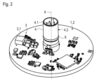
角度測定機構内で用いられるべき走査ユニットの一部が、図1では側面図で、または図2では透視図で示されている。これにより走査ユニットは、なかでも、剛性でガラス繊維強化されたエポキシ樹脂をベースとする円盤状または円形のプリント基板1を含んでいる。プリント基板1は、必然的に第1の表面1.1と、第1の表面1.1に向かい合っている第2の表面1.2とを有している。紹介している例示的実施形態では、走査ユニットは誘導式の測定原理に基づいている。それに応じて、第1の表面1.1に配置されている検出構成2は複数の受信巻線として形成されている。これに加えて第1の表面1.1には複数の励磁導体路10が配置されている。
A part of the scanning unit to be used in the angle measuring arrangement is shown in a side view in FIG. 1 and in a perspective view in FIG. The scanning unit thus includes, inter alia, a disk-shaped or circular printed circuit board 1 based on rigid, glass-fiber reinforced epoxy resin. The printed circuit board 1 necessarily has a first surface 1.1 and a second surface 1.2 facing the first surface 1.1. In the exemplary embodiment presented, the scanning unit is based on an inductive measuring principle. Accordingly, the
第2の表面1.2には、なかでも評価電子機器3の電子部品3.1が取り付けられている。プリント基板1の第2の表面1.2にはコンタクト支持体4も、例えばSMDプロセスによって取り付けられている。コンタクト支持体4は、差し込み接続の確立に適した電気コンタクト4.1(図2)を取り囲んでおり、この電気コンタクト4.1は、軸線Aに平行な方向に走っている。コンタクト支持体4は、幾何的に考察すると、実質的に円筒側面に相当する外壁4.2または外面を有している。外壁4.2は、周りを囲んでいる溝を有しており、この溝内に第1の弾性要素6、ここではOリングが配置されている。
On the second surface 1.2, inter alia, an electronic component 3.1 of the
走査ユニットはそのうえ、例えば図3に示したハウジング体5を有している。ハウジング体5は、ハウジング体5の剛性のリング状区間内に成形された底5.1を含んでいる。この底には、軸線Aを中心とする穴があり、この穴にスリーブ5.11がねじ込まれている。スリーブ5.11のフランジと底5.1との軸線方向の間に、第2の弾性要素7がある。第2の弾性要素7も、ここではOリングとして形成されている。スリーブ5.11は、端から端までの開口部Hを有しており、それに対応して内壁5.111を有している。内壁5.111は、凹面の中空円筒の幾何形状を有しており、この幾何形状の対称軸線は軸線Aである。
The scanning unit also has a
ハウジング体5は、底5.1の軸線方向の両側で、実質的に中空円筒の形状を有している。これに加えてハウジング体5は、リング状の端面に、加工されたストッパ面5.4を有している。
The
ハウジング体5の軸線方向の変形性が達成されるよう、紹介している例示的実施形態では、複数の、それぞれハウジング体5の部分外周にわたって入れられた切れ目5.21、5.22、5.23、5.24が設けられている。これらの切れ目は、例えば図3および図4で、ハッチングされた断面の間の領域で明らかになっているように、ハウジング体5の壁を径方向に完全に貫通している。これらの切れ目5.21、5.22、5.23、5.24の周方向の間には、軸線方向に走っているブリッジ部5.31、5.32、5.33、5.34が存在している。とりわけ、切れ目5.21、5.22、5.23、5.24は鋸切削プロセスによって生成することができ、軸線方向に延びているブリッジ部5.31、5.32、5.33、5.34はそのままにされる。この場合、ハウジング体5は、除去されなかった領域がメアンダー状の形を有するように形成されている。つまり、ブリッジ部5.31、5.32、5.33、5.34は、そのままにされた材料のうち軸線方向成分において走っている領域である。
In order to achieve axial deformability of the
切れ目5.21、5.22、5.23、5.24は、ペアにまとめることができ、図では、符号において同じ最終番号をもつ切れ目が1つのペアに属している(したがって同じ符号をもつそれぞれ2つの切れ目が存在している)。紹介している例示的実施形態では、ハウジング体5は、切れ目5.21、5.22、5.23、5.24のそれぞれ4つのペアを有している。
Breaks 5.21, 5.22, 5.23, 5.24 can be grouped together in pairs, and in the figure breaks with the same final number in the code belong to one pair (and therefore have the same sign). There are two breaks in each). In the exemplary embodiment presented, the
例えば、切れ目の第1のペアは切れ目5.21を有しており、これらの切れ目5.21は、軸線A上の一点に対して(点)対称に配置されている。同じことが、切れ目の第2のペアに割り当てられ得る切れ目5.22ならびに第3および第4のペアに当てはまる。 For example, the first pair of cuts has cuts 5.21, which are arranged symmetrically with respect to a point on the axis A. The same applies to cuts 5.22 and the third and fourth pairs, which can be assigned to the second pair of cuts.
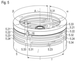
図5から分かるように、ここでは、切れ目の第1のペアの切れ目5.21が切れ目の第2のペアの切れ目5.22に対し、軸線方向にずれて、かつ外周に沿って約90°ずれて配置されている。 As can be seen in FIG. 5, here the cuts 5.21 of the first pair of cuts are axially offset with respect to the cuts 5.22 of the second pair of cuts and about 90° along the outer circumference. They are placed out of alignment.
切れ目5.21、5.22、5.23、5.24は、約170°の外周角度βにわたって延びている。
切れ目の第1のペアの切れ目5.21は第1の幾何平面内にあり、かつ切れ目の第2のペアの切れ目5.22は、第1の幾何平面に対して軸線方向にずれて配置されている第2の幾何平面内にある。第1の幾何平面も第2の幾何平面も、それぞれの平面のそれぞれの法線ベクトルが軸線Aに平行に方向づけられるように配置されている。紹介している例示的実施形態では、同じ考察が、切れ目5.23;5.24の第3および第4のペアにも当てはまる。
The cuts 5.21, 5.22, 5.23, 5.24 extend over a circumferential angle β of approximately 170°.
The cuts 5.21 of the first pair of cuts lie in the first geometric plane, and the cuts 5.22 of the second pair of cuts are arranged axially offset with respect to the first geometric plane. is in the second geometric plane. Both the first geometric plane and the second geometric plane are arranged such that the respective normal vectors of the respective planes are oriented parallel to the axis A. In the exemplary embodiment presented, the same considerations apply to the third and fourth pair of breaks 5.23; 5.24.
ブリッジ部5.31、5.32、5.33、5.34も、4つのペアにまとめることができ、ハウジング体5は、ここでは全部で8つのブリッジ部5.31、5.32、5.33、5.34を有しており、これらのブリッジ部のうち、図5では6つが見えている。ブリッジ部の第1のペアはブリッジ部5.31を含んでおり、これらのブリッジ部5.31は、軸線A上の一点に対して(点)対称に配置されている。第1のペアのブリッジ部5.31は、互いに対して角度α=180°周方向にずれて配置されている。同じことが、ブリッジ部の第2のペアに割り当てられ得るブリッジ部5.32ならびに第3および第4のペアのブリッジ部5.33、5.34に当てはまる。ブリッジ部の第1のペアのブリッジ部5.31はブリッジ部の第2のペアのブリッジ部5.32に対し、軸線方向にずれて、かつ外周に沿って外周角度γ、ここでは90°ずれて配置されている。紹介している例示的実施形態では、ブリッジ部5.31、5.32、5.33、5.34の4つのペアは、互いに対して軸線方向にずれて配置されている。ここでは、第1および第3のペアのブリッジ部5.31、5.33が、第2および第4のペアのブリッジ部5.32、5.34に対して同じ外周角度γだけずれて配置されている。
The bridge parts 5.31, 5.32, 5.33, 5.34 can also be combined into four pairs, the
さらに、ハウジング体5はブリッジ部の第1のペアを有するように形成されており、この第1のペアのブリッジ部5.31は、軸線Aに平行に法線ベクトルが方向づけられた仮想平面内に配置されている。言い換えれば、軸線Aは上記の平面と垂直に交わっている。同じ考察が、ブリッジ部の第2のペアのブリッジ部5.32にも当てはまり、これらのブリッジ部5.32が置かれている平面は、ブリッジ部の第1のペアのための当該平面に対して軸線方向にずれて配置されている。
Furthermore, the
走査ユニットは、ブリッジ部5.31、5.32、5.33、5.34を有しており、これらのブリッジ部の軸線方向の間には1つの切れ目5.21、5.22、5.23、5.24が配置されており、したがってこれらのブリッジ部5.31、5.32、5.33、5.34は軸線方向にずれて配置されている。とりわけ、同一線上に並んで軸線方向にずれて配置されているブリッジ部5.31、5.33の間に、切れ目5.22が配置されている。同様に、同一線上に並んで軸線方向にずれて配置されているブリッジ部5.32、5.34の間に、切れ目5.23が配置されている。 The scanning unit has bridge parts 5.31, 5.32, 5.33, 5.34 with one cut 5.21, 5.22, 5 between these bridge parts in the axial direction. .23, 5.24 are arranged, so that these bridge parts 5.31, 5.32, 5.33, 5.34 are arranged offset in the axial direction. In particular, a cut 5.22 is arranged between bridge parts 5.31, 5.33 which are arranged colinear and axially offset. Similarly, a cut 5.23 is arranged between the bridge parts 5.32, 5.34, which are arranged colinear and offset in the axial direction.
紹介している例示的実施形態では、ハウジング体5は、スリーブ5.11を除いて一体的にまたは一つの部分から成って形成されている。とりわけ、ハウジング体5はアルミニウム材料から製造されている。
In the exemplary embodiment presented, the
走査ユニットを組み立てる過程では、プリント基板1がコンタクト支持体4と一緒に第1の弾性要素6もろとも、ハウジング体5と組み合わせられ、これにより、例えば図4に示したような構成が存在している。これに対応して、コンタクト支持体4が開口部H内に突き出ている。開口部Hの内壁5.111とコンタクト支持体4の外壁4.2の間には、第1の弾性要素6が、径方向の予応力がかかった状態で、つまり径方向に押しつぶされて配置されている。この予応力によりコンタクト支持体4は、開口部Hの内壁5.111に対し、さらなる関与なく、センタリングされて配置されている。ハウジング体5の造形およびプリント基板1の寸法決定により、プリント基板1はハウジング体5に対して第1の隙間Gr(図4)をあけて、径方向に離隔して配置されている。
In the course of assembling the scanning unit, the printed circuit board 1 together with the
角度測定機構全体が精密に機能するには、検出構成2を備えたプリント基板1が、軸線Aに対してセンタリングされて配置されることが重要なだけでなく、この関連で、プリント基板1の規定の軸線方向の位置が確立されることも重要である。紹介している例示的実施形態では、プリント基板1の第1の表面1.1が、ハウジング体5のストッパ面5.4に揃えて取り付けられる。
For the entire angle measuring mechanism to function precisely, it is not only important that the printed circuit board 1 with the
このために、最初にプリント基板1ができるだけ、つまりぶつかるまでハウジング体5内に押し込まれる。その後、接着剤8が、周りを囲んでいる隙間Gr内にもたらされる。その次に、ストッパ面5.4が平らな面に押し付けられる。その後、プリント基板1が平らな面と接触して上記の揃った構成が達成されるまで、コンタクト支持体4が開口部Hに対して変位される。ここでは、コンタクト支持体4が取付補助工具でプリント基板1の方向に押される場合が有利であり得る。この位置では、プリント基板1の第2の表面1.2はハウジング体5に当接しておらず、むしろ軸線方向の第2の隙間Gaが存在しており、これはここでは結果的に、まだ硬化してない接着剤8が毛管効果によりこの第2の隙間Ga内に入り込むことになる。ハウジング体5の軸線方向の予応力およびコンタクト支持体4への軸線方向の圧力により、プリント基板1とストッパ面5.4の間の厳密に揃った位置が維持されることが保証される。つまり、第1の隙間Grおよび第2の隙間Gaは、この段階では接着剤8(図6)によって塞がれており、この接着剤8は、後に例えば加熱炉内で硬化される。接着剤8の硬化後、プリント基板1はハウジング体5と不動におよびとりわけ回転剛性をもって結合しており、したがってこれで、ハウジング体5の軸線方向の予応力が取り除かれ得る。これにより電子部品3.1は、例えば潤滑剤または水分の侵入のような外部の影響に対し、および機械的な影響に対し、効果的に遮蔽されている。
For this purpose, the printed circuit board 1 is first pushed into the
図3~図5に基づく走査ユニットおよび角度スケール9は、図6に基づいて一緒に角度測定機構を構成し、この角度測定機構は、ここでは誘導式角度測定機構として形成されており、つまり誘導式の測定原理に基づいている。角度スケール9は、紹介している例示的実施形態では、リング状の基板として形成されており、この基板上では、周期的シーケンスおよび同じ目盛ピッチで、導電性および非導電性の領域、つまり導電性の異なる領域が設けられている。角度スケール9は、ハブ15と回転不能に結合されている。
The scanning unit and the
図6は、誘導式走査ユニットを備えており、かつこの走査ユニットがモータに取り付けられている角度測定機構を示している。モータは、固定子側のブレーキを有しており、ブレーキはアンカーディスク12を含んでいる。さらにモータは、モータのハウジングおよびアンカーディスク12に対して回転可能な軸13を有している。軸13とハブ15は、回転不能に、およびプリント基板1と角度スケール9の間に隙間幅Dで厳密にアライメントされた空隙をあけて、結合される。このために軸13は、ハブ15の雄ネジ山に噛み合い得る第1の雌ネジ山13.1を有している。したがって軸13とハブ15の間の相応の相対回転により、ハブ15の軸13に対する軸線方向の変位が達成され得る。ハブ15を軸13に取り付ける過程では、最初にハブ15が軸13内にねじ込まれ、補助工具により、ハウジング12の上縁と角度スケール9の表面との間隔または隙間幅D、ここでは例えば1.4mmが、厳密に調整される。この位置に達するとすぐに、中心のネジ16が、軸13の第2の(より小さい)雌ネジ山13.2内に回し込まれる。これは結果的に、軸13およびハブ15のネジ山の間隔がぴったり押し付けられることになり、したがってこれにより、目盛構造をもつ角度スケール9が軸13に回転不能に据え付けられている。
FIG. 6 shows an angle measuring arrangement with an inductive scanning unit, which scanning unit is attached to a motor. The motor has a stator-side brake, which includes an
その後、走査ユニット、とりわけハウジング体5が、モータのアンカーディスク12に固定される。ハウジング体5のアンカーディスク12に対する相対回転が回避されるように、ハウジング体5は、固定子側のいわゆるコイルボビン14の溝に挿入される滑りキー16(図5)を有している。これに加え、ハウジング体5に軸線方向に予応力がかけられ、したがってハウジング体5は弾性変形しており、かつ切れ目5.21、5.22、5.23、5.24の軸線方向の隙間幅が、応力を取り除いた状態に比べて減少している。この軸線方向の予応力を保つため、図6に基づき、周りを囲んでいる安全リング11(ここでは止め輪)が取り付けられる。こうすることで、走査ユニットがハウジング体5のストッパ面5.4で、モータのアンカーディスク12に永続的に突っ張り支持されることが保証されている。アンカーディスク12からストッパ面5.4が浮き上がることは、モータの比較的強い振動の際または衝突の発生の際にもあり得ない。ストッパ面5.4に対するプリント基板1の揃った配置により、プリント基板1と角度スケール9の間隔は、予め調整された隙間幅Dに相当している。
The scanning unit, in particular the
ハウジング体5は上述の構造方式により、軸線方向には柔軟だが、ねじり剛性および径方向剛性をもって形成されている。
角度測定機構の動作中は、角度スケール9が走査ユニットに対して軸線Aの周りを回転する。この相対回転性を達成するために、この角度測定機構では自己軸受部、つまりころ軸受またはすべり軸受は設けられておらず、したがって紹介している例示的実施形態では、軸受なしの角度測定機構である。
Due to the construction described above, the
During operation of the angle measuring mechanism, the
つまり、角度スケール9および走査ユニットは互いに対して相対的に回転可能に配置されており、軸13に固定された角度スケール9が、角度測定機構の動作中に回転する。それゆえここでは、角度スケール9と走査ユニットの間の相対回転数は、軸13と定置のハウジング体5の間の回転数にも相当する。固定子側の走査ユニット上での回転しない励磁コイル10により、この角度測定機構の動作中には均質な交流場が生成され、この交流場が、角度スケール9により、角度位置または軸13の回転角度に応じて変調される。同様に走査ユニット上にある検出構成2内では、変調された電磁場により、角度に応じた信号が生成される。検出構成2、つまりここでは受信巻線によって生成された信号は、評価電子機器3により、走査ユニットと角度スケール9の間の相対的な角度位置が決定されるようにさらに処理される。ハウジング体5内にある差込コネクタまたは電気コンタクト4.1は、図では示されていない接続ケーブルと接触し、この接続ケーブルは、それに続く電子機器につながっている。
That is, the
基本的には、測定構成が実際の走査間隔Dの変化にも反応することが確認され得る。走査間隔Dは、固定子側のブレーキがかかっているか否かの情報を内包している。したがって、ブレーキのそれぞれ目下の状態(かかっているまたは解除されている)が、走査ユニットによって確定され得る。 In principle, it can be confirmed that the measurement arrangement is also sensitive to changes in the actual scanning interval D. The scanning interval D includes information as to whether or not the brake on the stator side is applied. The respective current state of the brake (applied or released) can thus be determined by the scanning unit.
紹介している例示的実施形態では、角度測定機構は、いわゆる全周走査に基づいて構成されている。つまりとりわけ、走査ユニットは、走査ユニットまたは検出構成2によって角度スケール9をほぼ全周にわたって走査可能であるように、かつこうして角度に応じた出力信号を生成可能であるように形成されている。つまり、位置信号を取得するために、角度スケール9のほぼ全部の目盛構造が走査ユニットによって走査される。
In the exemplary embodiment presented, the angle measurement arrangement is configured on the basis of a so-called full-circle scanning. In particular, the scanning unit is designed in such a way that the scanning unit or
図7に基づいて、第1の例示的実施形態とはハウジング体5’の代替的な形態によって異なっている第2の例示的実施形態が示される。この変形形態により、走査ユニットのクランプ締めでの取付が可能にされ得る。ハウジング体5’は、軸線方向に走っている2つのスリット5.5および楔形要素5.6を有しており、楔形要素5.6は、クランプネジ5.7によって軸線方向に移動させ得る。これにより、この領域内でのハウジング体5’の外輪郭を径方向外側へと押しやることができ、これは、モータハウジングの対応する寸法決定の場合、ハウジング体5’の永続的なクランプ締めを生じさせる。
Based on FIG. 7, a second exemplary embodiment is shown which differs from the first exemplary embodiment by an alternative form of the housing body 5'. This variant may allow clamping mounting of the scanning unit. The housing body 5' has two axially running slits 5.5 and a wedge-shaped element 5.6, which can be moved axially by means of a clamping screw 5.7. This makes it possible to push the outer contour of the housing body 5' in this area radially outwards, which, in the case of corresponding dimensioning of the motor housing, leads to permanent clamping of the
1 プリント基板
1.1 第1の表面
1.2 第2の表面
2 検出構成
3 評価電子機器
3.1 電子部品
4 コンタクト支持体
4.1 電気コンタクト
4.2 外壁
5、5’ ハウジング体
5.1 底
5.11 スリーブ
5.111 内壁
5.21、5.22、5.23、5.24 切れ目
5.31、5.32、5.33、5.34 ブリッジ部
5.4 ストッパ面
5.5 スリット
5.6 楔形要素
5.7 クランプネジ
6 第1の弾性要素
7 第2の弾性要素
8 接着剤
9 角度スケール
10 励磁コイル
11 安全リング
12 アンカーディスク、ハウジング
13 軸
13.1 第1の雌ネジ山
13.2 第2の(より小さい)雌ネジ山
14 コイルボビン
15 ハブ
16 ネジ
16 滑りキー
A 軸線
D 隙間幅、走査間隔
Gr 第1の隙間
Ga 第2の隙間
H 開口部
α 角度
β 外周角度
γ 外周角度
1 Printed circuit board 1.1 First surface 1.2
Claims (11)
- 第1の表面(1.1)および第2の表面(1.2)を有するプリント基板(1)、
- 前記プリント基板(1)の前記第1の表面(1.1)に向かい合っている前記角度スケール(9)を走査可能であるように配置されている検出構成(2)、
- 評価電子機器(3)、
- 差し込み接続を確立するための電気コンタクト(4.1)を取り囲んでおり、かつ外壁(4.2)を有しており、かつ前記プリント基板(1)の前記第2の表面(1.2)に取り付けられているコンタクト支持体(4)を含んでおり、したがって前記電気コンタクト(4.1)が軸線方向成分をもつ方向に走っており、
- 内壁(5.111)を有する開口部(H)を有するハウジング体(5;5’)を含んでおり、
前記コンタクト支持体(4)が前記開口部(H)内に突き出ており、前記開口部(H)の前記内壁(5.111)と前記コンタクト支持体(4)の前記外壁(4.2)の間には、径方向の予応力がかかった第1の弾性要素(6)が配置されており、これにより前記コンタクト支持体(4)が、前記開口部(H)の前記内壁(5.111)に対してセンタリングされて配置されており、かつ
前記プリント基板(1)が、前記ハウジング体(5;5’)に対して第1の隙間(Gr)をあけて、前記ハウジング体(5;5’)に対して径方向に離隔して、前記ハウジング体(5;5’)と回転剛性をもって結合している、走査ユニット。 A scanning unit for determining the relative angular position of an angular scale (9) rotatable with respect to the scanning unit about an axis (A), comprising:
- a printed circuit board (1) having a first surface (1.1) and a second surface (1.2);
- a detection arrangement (2) arranged to be able to scan said angular scale (9) facing said first surface (1.1) of said printed circuit board (1);
- Evaluation electronic equipment (3),
- surrounding electrical contacts (4.1) for establishing a plug connection and having an outer wall (4.2) and said second surface (1.2) of said printed circuit board (1); ), the electrical contacts (4.1) therefore running in a direction with an axial component;
- comprises a housing body (5; 5') having an opening (H) with an inner wall (5.111);
Said contact support (4) projects into said opening (H), said inner wall (5.111) of said opening (H) and said outer wall (4.2) of said contact support (4) A first radially prestressed elastic element (6) is arranged between, which forces the contact support (4) against the inner wall (5. 111), and the printed circuit board (1) is arranged with a first gap (Gr) between the housing body (5; 5') and the housing body (5; 5'). a scanning unit which is radially spaced apart from the housing body (5; 5') and rotationally rigidly connected to said housing body (5; 5');
11. Scanning unit according to claim 10, wherein the second elastic element (7) is formed as an O-ring.
Applications Claiming Priority (2)
| Application Number | Priority Date | Filing Date | Title |
|---|---|---|---|
| EP19152247.3A EP3683551B1 (en) | 2019-01-17 | 2019-01-17 | Sampling unit for an angle measuring device |
| EP19152247.3 | 2019-01-17 |
Publications (2)
| Publication Number | Publication Date |
|---|---|
| JP2020115129A JP2020115129A (en) | 2020-07-30 |
| JP7370872B2 true JP7370872B2 (en) | 2023-10-30 |
Family
ID=65036647
Family Applications (1)
| Application Number | Title | Priority Date | Filing Date |
|---|---|---|---|
| JP2020004169A Active JP7370872B2 (en) | 2019-01-17 | 2020-01-15 | Scanning unit for angle measuring mechanism |
Country Status (5)
| Country | Link |
|---|---|
| US (1) | US20200232820A1 (en) |
| EP (1) | EP3683551B1 (en) |
| JP (1) | JP7370872B2 (en) |
| CN (1) | CN111442787A (en) |
| DE (1) | DE102019007667A1 (en) |
Families Citing this family (5)
| Publication number | Priority date | Publication date | Assignee | Title |
|---|---|---|---|---|
| JP7295686B2 (en) * | 2019-03-29 | 2023-06-21 | ミネベアミツミ株式会社 | absolute encoder |
| DE102020203275A1 (en) * | 2020-03-13 | 2021-09-16 | Robert Bosch Gesellschaft mit beschränkter Haftung | Inductive rotor position sensor device, drive device |
| DE102020214235A1 (en) * | 2020-11-12 | 2022-05-12 | Robert Bosch Gesellschaft mit beschränkter Haftung | Inductive position sensor device, drive device |
| CN112414252B (en) * | 2020-11-19 | 2022-02-11 | 江苏理工学院 | Device and method for quickly detecting quality of cylindrical products produced in batch |
| JP2023122333A (en) * | 2022-02-22 | 2023-09-01 | 住友重機械工業株式会社 | Rotation detection device |
Citations (2)
| Publication number | Priority date | Publication date | Assignee | Title |
|---|---|---|---|---|
| JP2006145542A (en) | 2004-11-23 | 2006-06-08 | Dr Johannes Heidenhain Gmbh | Modular encoder, method for manufacturing the same and system for measuring angular motion |
| US20080289838A1 (en) | 2007-04-19 | 2008-11-27 | Francois Niarfeix | Instrumented joint system |
Family Cites Families (12)
| Publication number | Priority date | Publication date | Assignee | Title |
|---|---|---|---|---|
| DE19546865C1 (en) * | 1995-12-15 | 1996-10-02 | Vdo Schindling | Magnetic field sensor assembly method |
| JP4001989B2 (en) | 1996-11-29 | 2007-10-31 | ドクトル・ヨハネス・ハイデンハイン・ゲゼルシヤフト・ミツト・ベシユレンクテル・ハフツング | Scanning member of position measuring device |
| JP3840489B1 (en) * | 2005-04-28 | 2006-11-01 | Tdk株式会社 | Moving object detection device |
| DE102008015837A1 (en) * | 2008-03-27 | 2009-10-01 | Dr. Johannes Heidenhain Gmbh | Position measuring device and method for its operation |
| DE102008046741A1 (en) | 2008-09-11 | 2010-03-18 | Dr. Johannes Heidenhain Gmbh | Inductive position sensor, measuring system equipped therewith and method for operating a position sensor |
| JP5344375B2 (en) * | 2009-09-30 | 2013-11-20 | 日本精機株式会社 | Rotation angle detector |
| US8455831B2 (en) * | 2010-12-31 | 2013-06-04 | Rockwell Automation Technologies, Inc. | Sensing assembly having an oblique viewing angle range and methods of assembling, mounting and orienting the same |
| DE102012202683A1 (en) * | 2012-02-22 | 2013-08-22 | Dr. Johannes Heidenhain Gmbh | encoders |
| DE102012216854A1 (en) * | 2012-09-20 | 2014-03-20 | Dr. Johannes Heidenhain Gmbh | Position measuring device and method for its operation |
| EP2905582B1 (en) * | 2014-02-11 | 2016-10-05 | Dr. Johannes Heidenhain GmbH | Pre-assembled angle measuring device |
| DE102014205397A1 (en) * | 2014-03-24 | 2015-09-24 | Dr. Johannes Heidenhain Gmbh | Sensing element for an inductive angle measuring device |
| JP6766499B2 (en) * | 2016-07-25 | 2020-10-14 | 日本電産トーソク株式会社 | Sensor mounting structure |
-
2019
- 2019-01-17 EP EP19152247.3A patent/EP3683551B1/en active Active
- 2019-11-06 DE DE102019007667.2A patent/DE102019007667A1/en not_active Withdrawn
-
2020
- 2020-01-15 JP JP2020004169A patent/JP7370872B2/en active Active
- 2020-01-16 US US16/744,213 patent/US20200232820A1/en active Pending
- 2020-01-16 CN CN202010046799.3A patent/CN111442787A/en active Pending
Patent Citations (2)
| Publication number | Priority date | Publication date | Assignee | Title |
|---|---|---|---|---|
| JP2006145542A (en) | 2004-11-23 | 2006-06-08 | Dr Johannes Heidenhain Gmbh | Modular encoder, method for manufacturing the same and system for measuring angular motion |
| US20080289838A1 (en) | 2007-04-19 | 2008-11-27 | Francois Niarfeix | Instrumented joint system |
Also Published As
| Publication number | Publication date |
|---|---|
| JP2020115129A (en) | 2020-07-30 |
| EP3683551A1 (en) | 2020-07-22 |
| CN111442787A (en) | 2020-07-24 |
| US20200232820A1 (en) | 2020-07-23 |
| DE102019007667A1 (en) | 2020-07-23 |
| EP3683551B1 (en) | 2021-03-10 |
Similar Documents
| Publication | Publication Date | Title |
|---|---|---|
| JP7370872B2 (en) | Scanning unit for angle measuring mechanism | |
| CN108375333B (en) | Sensor for position measurement | |
| US7509883B2 (en) | Torque detecting apparatus and manufacturing method thereof | |
| US7637019B2 (en) | Rotary encoder | |
| JP7419075B2 (en) | Scanning unit for angle measuring mechanism | |
| US7392588B2 (en) | Rotary encoder | |
| JP6569306B2 (en) | motor | |
| CN110220538B (en) | Multi-turn rotary encoder | |
| US20140354118A1 (en) | Encoder for a compact revolution transmitter and electric motor with a compact revolution transmitter | |
| US9012831B2 (en) | Rotary encoder | |
| CN104949613B (en) | Scanning element for an inductive angle measuring device | |
| US11099035B2 (en) | Scanning unit for scanning an angular scale and angle-measuring device having such a scanning unit | |
| US10627262B2 (en) | Sensor unit for position measurement | |
| US10697751B2 (en) | Rotating shaft position encoder system | |
| JP2007221977A (en) | Brushless motor | |
| US11733066B2 (en) | Assembly having a rotary encoder and a tolerance ring | |
| JP2021125966A (en) | Power generation device and bearing with sensor | |
| US11506516B2 (en) | Scanning unit and rotary encoder equipped therewith | |
| CN114270144A (en) | Rotation angle measuring device, rotation angle measuring system, and motor | |
| JP2012007706A (en) | Rolling bearing with sensor |
Legal Events
| Date | Code | Title | Description |
|---|---|---|---|
| A621 | Written request for application examination |
Free format text: JAPANESE INTERMEDIATE CODE: A621 Effective date: 20221021 |
|
| TRDD | Decision of grant or rejection written | ||
| A977 | Report on retrieval |
Free format text: JAPANESE INTERMEDIATE CODE: A971007 Effective date: 20231011 |
|
| A01 | Written decision to grant a patent or to grant a registration (utility model) |
Free format text: JAPANESE INTERMEDIATE CODE: A01 Effective date: 20231012 |
|
| A61 | First payment of annual fees (during grant procedure) |
Free format text: JAPANESE INTERMEDIATE CODE: A61 Effective date: 20231018 |
|
| R150 | Certificate of patent or registration of utility model |
Ref document number: 7370872 Country of ref document: JP Free format text: JAPANESE INTERMEDIATE CODE: R150 |