JP7370834B2 - Electronic equipment and control methods - Google Patents
Electronic equipment and control methods Download PDFInfo
- Publication number
- JP7370834B2 JP7370834B2 JP2019217499A JP2019217499A JP7370834B2 JP 7370834 B2 JP7370834 B2 JP 7370834B2 JP 2019217499 A JP2019217499 A JP 2019217499A JP 2019217499 A JP2019217499 A JP 2019217499A JP 7370834 B2 JP7370834 B2 JP 7370834B2
- Authority
- JP
- Japan
- Prior art keywords
- charging
- battery
- voltage
- communication
- electronic device
- Prior art date
- Legal status (The legal status is an assumption and is not a legal conclusion. Google has not performed a legal analysis and makes no representation as to the accuracy of the status listed.)
- Active
Links
- 238000000034 method Methods 0.000 title claims description 69
- 238000007600 charging Methods 0.000 claims description 271
- 238000004891 communication Methods 0.000 claims description 139
- 230000008859 change Effects 0.000 claims description 47
- 238000001514 detection method Methods 0.000 claims description 29
- 230000008569 process Effects 0.000 description 44
- 230000006866 deterioration Effects 0.000 description 33
- 230000001186 cumulative effect Effects 0.000 description 12
- 238000003860 storage Methods 0.000 description 7
- 238000010586 diagram Methods 0.000 description 5
- 230000006870 function Effects 0.000 description 5
- 238000003384 imaging method Methods 0.000 description 4
- 238000005259 measurement Methods 0.000 description 4
- 238000010277 constant-current charging Methods 0.000 description 3
- 238000004364 calculation method Methods 0.000 description 2
- 238000006243 chemical reaction Methods 0.000 description 2
- 238000010280 constant potential charging Methods 0.000 description 2
- 230000005540 biological transmission Effects 0.000 description 1
- 238000010281 constant-current constant-voltage charging Methods 0.000 description 1
- 238000004519 manufacturing process Methods 0.000 description 1
- 230000003287 optical effect Effects 0.000 description 1
- 230000009467 reduction Effects 0.000 description 1
- 230000004044 response Effects 0.000 description 1
- 230000001568 sexual effect Effects 0.000 description 1
- 238000004904 shortening Methods 0.000 description 1
- 230000002123 temporal effect Effects 0.000 description 1
- 239000002699 waste material Substances 0.000 description 1
Images


Classifications
-
- H—ELECTRICITY
- H02—GENERATION; CONVERSION OR DISTRIBUTION OF ELECTRIC POWER
- H02J—CIRCUIT ARRANGEMENTS OR SYSTEMS FOR SUPPLYING OR DISTRIBUTING ELECTRIC POWER; SYSTEMS FOR STORING ELECTRIC ENERGY
- H02J7/00—Circuit arrangements for charging or depolarising batteries or for supplying loads from batteries
- H02J7/00032—Circuit arrangements for charging or depolarising batteries or for supplying loads from batteries characterised by data exchange
- H02J7/00034—Charger exchanging data with an electronic device, i.e. telephone, whose internal battery is under charge
-
- H—ELECTRICITY
- H02—GENERATION; CONVERSION OR DISTRIBUTION OF ELECTRIC POWER
- H02J—CIRCUIT ARRANGEMENTS OR SYSTEMS FOR SUPPLYING OR DISTRIBUTING ELECTRIC POWER; SYSTEMS FOR STORING ELECTRIC ENERGY
- H02J7/00—Circuit arrangements for charging or depolarising batteries or for supplying loads from batteries
- H02J7/007—Regulation of charging or discharging current or voltage
- H02J7/007188—Regulation of charging or discharging current or voltage the charge cycle being controlled or terminated in response to non-electric parameters
-
- H—ELECTRICITY
- H02—GENERATION; CONVERSION OR DISTRIBUTION OF ELECTRIC POWER
- H02J—CIRCUIT ARRANGEMENTS OR SYSTEMS FOR SUPPLYING OR DISTRIBUTING ELECTRIC POWER; SYSTEMS FOR STORING ELECTRIC ENERGY
- H02J7/00—Circuit arrangements for charging or depolarising batteries or for supplying loads from batteries
- H02J7/00032—Circuit arrangements for charging or depolarising batteries or for supplying loads from batteries characterised by data exchange
- H02J7/00036—Charger exchanging data with battery
-
- H—ELECTRICITY
- H02—GENERATION; CONVERSION OR DISTRIBUTION OF ELECTRIC POWER
- H02J—CIRCUIT ARRANGEMENTS OR SYSTEMS FOR SUPPLYING OR DISTRIBUTING ELECTRIC POWER; SYSTEMS FOR STORING ELECTRIC ENERGY
- H02J7/00—Circuit arrangements for charging or depolarising batteries or for supplying loads from batteries
- H02J7/0047—Circuit arrangements for charging or depolarising batteries or for supplying loads from batteries with monitoring or indicating devices or circuits
Description
本発明は、外部機器から供給される電力で電池を充電する電子機器、制御方法などに関するものである。 TECHNICAL FIELD The present invention relates to an electronic device that charges a battery with power supplied from an external device, a control method, and the like.
特許文献1には、定電流充電および定電圧充電を行う非接触電力伝送システムにおいて、定電圧充電が行われる場合の通信頻度を定電流充電が行われる場合の通信頻度よりも高くする方法が記載されている。
特許文献1には、定電圧充電が行われる場合の通信頻度を定電流充電が行われる場合の通信頻度よりも高くする方法が記載されている。しかしながら、この方法だけでは、電池の充電時間を短縮したいという課題を解決することはできない。
そこで、本発明は、電池の充電時間を短縮できるようにすることを目的とする。 Therefore, an object of the present invention is to make it possible to shorten the charging time of a battery.
上記課題を解決するために、本発明に係る電子機器の一つは、外部機器と通信する通信手段と、前記外部機器から供給された電力を受け取る受電手段と、前記受電手段が前記外部機器から受け取った電力により電池を充電する充電手段と、前記充電手段により前記電池を充電する場合に、前記電子機器が前記外部機器に電力を要求するための所定の通信を行うように、前記通信手段を制御する制御手段とを有し、前記充電手段により前記電池を充電する場合に、前記制御手段は、前記充電手段により前記電池の充電を開始してから前記電池の電圧が所定の電圧となるまでの、前記所定の通信を行う間隔が、前記電池の電圧が前記所定の電圧となった後の、前記所定の通信を行う間隔よりも短くなるように、前記通信手段を制御する。
上記課題を解決するために、本発明に係る電子機器の一つは、外部機器と通信する通信手段と、前記外部機器から供給された電力を受け取る受電手段と、前記受電手段が前記外部機器から受け取った電力により電池を充電する充電手段と、前記充電手段により前記電池を充電する場合に、前記電子機器が前記外部機器に電力を要求するための所定の通信を行うように、前記通信手段を制御する制御手段とを有し、前記充電手段により前記電池の充電を開始してからの第1の期間における前記電池の電圧の時間変化に対応した充電カーブの勾配が、前記第1の期間の後の第2の期間における前記充電カーブの勾配よりも急である場合に、前記制御手段は、前記第1の期間において前記所定の通信を行う間隔が、前記第2の期間において前記所定の通信を行う間隔よりも短くなるように、前記通信手段を制御する。
In order to solve the above problems, one of the electronic devices according to the present invention includes a communication means for communicating with an external device, a power receiving means for receiving power supplied from the external device, and a power receiving means for receiving power from the external device. a charging means for charging a battery with the received power; and a communication means so that the electronic device performs predetermined communication to request power from the external device when the battery is charged by the charging means. and a control means for controlling, when the battery is charged by the charging means, the control means controls the battery from when the charging means starts charging the battery until the voltage of the battery reaches a predetermined voltage . The communication means is controlled such that the interval at which the predetermined communication is performed is shorter than the interval at which the predetermined communication is performed after the voltage of the battery reaches the predetermined voltage .
In order to solve the above problems, one of the electronic devices according to the present invention includes a communication means for communicating with an external device, a power receiving means for receiving power supplied from the external device, and a power receiving means for receiving power from the external device. a charging means for charging a battery with the received power; and a communication means so that the electronic device performs predetermined communication to request power from the external device when the battery is charged by the charging means. and a control means for controlling the slope of the charging curve corresponding to a time change in the voltage of the battery during a first period after the charging means starts charging the battery, the gradient of the charging curve corresponding to the time change of the voltage of the battery during the first period after the charging means starts charging the battery. If the slope of the charging curve in the second period is steeper than the slope of the charging curve in the second period, the control means may cause the predetermined communication to occur in the second period. The communication means is controlled so that the interval is shorter than the interval at which the communication is performed.
上記課題を解決するために、本発明に係る電子機器の一つは、外部機器と通信する通信手段と、前記外部機器から供給された電力を受け取る受電手段と、前記受電手段が前記外部機器から受け取った電力により電池を充電する充電手段と、前記充電手段により前記電池を充電する場合に、前記電子機器が前記外部機器に電力を要求するための所定の通信を行うように、前記通信手段を制御する制御手段とを有し、前記充電手段により前記電池を充電する場合に、前記制御手段は、前記電池の電圧の変化量が所定値を上回っている場合は、第1の間隔で前記所定の通信を行い、前記電池の電圧の変化量が前記所定値を上回っていない場合は、前記第1の間隔よりも短い第2の間隔で前記所定の通信を行うように前記通信手段を制御する。 In order to solve the above problems, one of the electronic devices according to the present invention includes a communication means for communicating with an external device, a power receiving means for receiving power supplied from the external device, and a power receiving means for receiving power from the external device. a charging means for charging a battery with the received power; and a communication means so that the electronic device performs predetermined communication to request power from the external device when the battery is charged by the charging means. and a control means for controlling the battery, and when the battery is charged by the charging means, the control means controls the voltage at the predetermined interval at a first interval when the amount of change in the voltage of the battery exceeds a predetermined value. and if the amount of change in the voltage of the battery does not exceed the predetermined value, the communication means is controlled to perform the predetermined communication at a second interval shorter than the first interval. .
本発明によれば、電池の充電時間を短縮することができる。 According to the present invention, battery charging time can be shortened.
以下、図面を参照して本発明の実施形態を説明する。ただし、本発明は以下の実施形態に限定されるものではない。 Embodiments of the present invention will be described below with reference to the drawings. However, the present invention is not limited to the following embodiments.
[実施形態1]
図1は、実施形態1における電子機器100とチャージャー300のシステム構成の一例を説明するための図である。なお、以下の実施形態において、電子機器100は、例えばデジタルカメラとして動作可能な機器である場合について説明するが、デジタルカメラに限らず、例えば、スマートフォンまたはタブレット端末として動作可能な機器であってもよい。
[Embodiment 1]
FIG. 1 is a diagram for explaining an example of a system configuration of an
電子機器100は、電池103が取り外し可能であり、電池103から供給される電力で動作する。電子機器100は、外部機器を接続可能な接続部101を有する。接続部101に接続される外部機器は、例えば、給電機器であるチャージャー300である。
The
また、電子機器100は、接続部101を介してチャージャー300と通信することおよびチャージャー300から電力を受け取ることが可能である。電子機器100はチャージャー300から受け取った電力により電池103を充電可能な受電機器である。また、電子機器100は電池103から供給される電力ではなく、チャージャー300から供給される電力で動作することもできる。電子機器100およびチャージャー300は、USB PD(Power Delivery)3.0のPPS(Programmable Power Supply)と呼ばれる機能を用いて、チャージャー300から電子機器100に電力を供給することができる。
Further, the
PPSでは、USB Type-CコネクタのCC(Configuration Channel)端子を介して通信を行い、電子機器100からの所定の電圧の電力要求に対して細かいステップで電圧または電流を変化させて電力供給を行うことができる。PPSによりチャージャー300から電子機器100に供給される電圧は、電子機器100とチャージャー300とが行うPPSに準拠した通信(以下、PPS通信)によって決まる。電子機器100は、要求電圧をPPS通信によりチャージャー300に通知することが可能である。チャージャー300は、充電時間の経過と共に要求電圧を適切に変更していくことで、定電流定電圧(Constant Current Constant Voltage:CCCV)充電を行うことができる。CCCV充電は、途中まで一定の電流値(Constant Current)でCC(定電流)充電を行い、所定の電圧に達したら一定の電圧(Constant Voltage)でCV(定電圧)充電を行う方法である。
In PPS, communication is performed via the CC (Configuration Channel) terminal of the USB Type-C connector, and power is supplied by changing the voltage or current in small steps in response to a power request for a predetermined voltage from the
図2は、電子機器100の構成要素を説明するためのブロック図である。
FIG. 2 is a block diagram for explaining the components of the
接続部101は、チャージャー300と通信することおよびチャージャー300から電力を受け取ることが可能なインターフェースである。接続部101は、例えばUSB Type-Cのコネクタであり、USB Type-Cケーブル200を介してチャージャー300と接続される。
充電制御部102は、接続部101を介してチャージャー300から受け取った電力を、電圧検出部104を介して電子機器100の構成要素に供給する。また、充電制御部102はチャージャー300から受け取った電力により電池103を充電することもできる。さらに、充電制御部102は、電池103から供給される電力を電子機器100の構成要素に供給することもできる。
電池103は、電子機器100を動作させるために必要な電力を供給する。電池103は、電子機器100から取り外し可能である。電池103は接続部101を介してチャージャー300から受け取った電力により充電される。
The
電圧検出部104は、電池103から供給される電力の電圧値または接続部101を介してチャージャー300から供給された電力の電圧値を検出することができる。
The voltage detection unit 104 can detect the voltage value of the power supplied from the
システム制御部105は、電子機器100の構成要素をプログラムに従って制御するマイクロコンピュータである。
The
電圧変換部106は、電池103または接続部101を介して供給される電力を昇圧または降圧し、電子機器100の構成要素に適した電圧に変換する。
The
撮像部109は、撮像部109に含まれるレンズで結像された被写体光を電気信号に変換し、ノイズ低減処理などを行い、画像データとして出力する。撮像部109により撮像した画像データはメモリ111に蓄えられた後、メイン制御部105において所定の演算を行い、記録媒体112に記録される。
The
表示部110は、撮影時のビューファインダー画像の表示、撮影した画像データの表示、操作のためのGUIの表示などを行う。
The
メモリ111は、システム制御部105による各種の処理に必要なプログラム、データ、画像データを一時記憶するRAMなどの揮発性メモリ、あるいは、これらのデータを電気的に消去・記録可能なEEPROMなどの不揮発性メモリである。
The
記録媒体112は、撮像部109から出力された画像データを所定のデータ形式に圧縮した画像ファイルを記録することができる。記録媒体112は、ハードディスク、メモリカード、USBフラッシュメモリなどを含む。記録媒体112は、電子機器100から取り外し可能である。
The
操作部113は、電子機器100に対する指示をユーザから受け付け、メイン制御部105に指示信号を通知する。操作部113は例えば、ユーザが電子機器100の電源のONまたはOFFを指示するための電源ボタン、撮影を指示するためのレリーズスイッチを含む。また、画像データの再生を指示するための再生ボタン、電子機器100の撮影モードを指示するモードダイヤル、表示部110に形成されるタッチパネルなども操作部113に含まれる。なお、レリーズスイッチは、SW1およびSW2を有する。レリーズスイッチが、いわゆる半押し状態となることにより、SW1がONとなる。これにより、メイン制御部105は、AF(オートフォーカス)処理、AE(自動露出)処理等の撮影準備を行うための指示を受け付ける。また、レリーズスイッチが、いわゆる全押し状態となることにより、SW2がONとなる。これにより、メイン制御部105は、撮影を行うための指示を受け付ける。
The
電圧変化量検出部114は、電圧検出部104により検出された電圧値に基づき、電池103または接続部101から供給される電力の電圧の変化量を計算する。
The voltage change amount detection unit 114 calculates the amount of change in the voltage of the power supplied from the
通信制御部115は、接続部101を介してチャージャー300と通信可能である。通信制御部115は、シャージャー300とのPPS通信を制御し、充電制御部102において計算された要求電圧を接続部101を介してチャージャー300に送信することができる。
タイマー116は、後述する要求電圧を送信するためのPPS通信における通信間隔などを計測する。 The timer 116 measures a communication interval in PPS communication for transmitting a required voltage, which will be described later.
内部メモリ117は、電池電圧に対する要求電圧のテーブル、電池電圧に対する時間閾値のテーブルを記憶するROMである。 The internal memory 117 is a ROM that stores a table of required voltages for battery voltages and a table of time thresholds for battery voltages.
電流検出部118は、接続部101を介して供給される電力の電流値(電池103の充電電流の値)または電池103から出力される電力の電流値を検出することができる。
The
電流変化量検出部119は、電流検出部118により検出された電流値に基づき、電池103または接続部101から供給される電力の電流値の変化量を計算する。
The current change
なお、図2において、電圧検出部104、電圧変化量検出部114、タイマー116、内部メモリ117、電流検出部118および電流変化量検出部119は、充電制御部102に含まれる構成となっているが、充電制御部102と別体に構成されてもよい。
Note that in FIG. 2, the voltage detection section 104, voltage change amount detection section 114, timer 116, internal memory 117,
<PPS通信>
次に、図3を参照して、電子機器100とチャージャー300のPPS通信時の動作について説明する。
<PPS communication>
Next, with reference to FIG. 3, the operation of
図3は、電子機器100とチャージャー300がUSB Type-CのCC端子を介してPPS通信を行う際の動作の一例を説明するためのタイムチャートである。
FIG. 3 is a time chart for explaining an example of the operation when the
図3において、PPS通信の矢印は、始点が通信の送信側、終点が通信の受信側に対応している。VBUS電圧はSource機器であるチャージャー300から出力され、Sink機器である電子機器100がUSB Type-CのVBUS端子から電力を受け取る。図3では、VBUS電圧の出力後、出力可能な電圧と電流を示すPDO(Power Data Object)が含まれているSource Capabilitiesをチャージャー300から受け取った後の電子機器100の動作の一例を示している。
In FIG. 3, the starting point of the PPS communication arrow corresponds to the sending side of the communication, and the ending point corresponds to the receiving side of the communication. The VBUS voltage is output from the
T101において、電子機器100は、要求したい電圧等が含まれている「Request」をチャージャー300に送信する。PPSでは出力電圧を、20mVを最小単位としてチャージャー300に要求することが可能である。
At T101, the
T102において、チャージャー300は電子機器100からの「Request」を受信し、「Request」を正しく受け取ったことを電子機器100に送信する。
At T102, the
T103において、チャージャー300は電子機器100からの「Request」の内容を確認し、有効であれば「Accept」を送信し、T104において電子機器100はそれを受信する。
At T103, the
T105において、電子機器100は、「Accept」を正しく受け取ったことをチャージャー300に送信する。そして、チャージャー300は、現在のVBUS電圧V1から、電子機器100から要求された電圧V2への変更を開始する。
At T105, the
T106において、チャージャー300は、VBUS電圧V1から電圧V2への変更が完了したら、「PS_RDY」を電子機器100に送信する。
At T106,
T107において、電子機器100は、「PS_RDY」を受信し、「PS_RDY」を正しく受け取ったことをチャージャー300に送信して、「SinkPPSPeriodicTimer」をスタートする。PPS通信では、Sinkは定期的にSourceに「Request」を送信する必要がある。「SinkPPSPeriodicTimer」の最大値は10秒と規格で定められており、「SinkPPSPeriodicTimer」で定めた時間ごとにSinkはSourceに「Request」を送信する。
At T107, the
T108において、チャージャー300は電子機器100から「PS_RDY」を正しく受け取ったことが通知された後、「PPSCommTimer」をスタートする。PPS通信では、Sourceは定期的にSinkから「Request」を受信する必要がある。「PPSCommTimer」の最小値は12秒、最大値は15秒と規格で定められており、「PPSCommTimer」がタイムアウトすると、SourceはHardReset信号を発行する。
At T108, after the
T107から「SinkPPSPeriodicTimer」の時間が経過すると、T109において、電子機器100は、要求したい電圧等が含まれている「Request」を再度送信する。PPSでは以上のような通信と電圧変更を繰り返す。
When the time period of "SinkPPSPperiodicTimer" has elapsed from T107, the
図4は、電子機器100とチャージャー300をUSB Type-Cケーブルにより接続し、PPSにより電池103を充電したときのVBUS電圧、電池電圧、充電電流の時間変化の一例を示している。
FIG. 4 shows an example of temporal changes in the VBUS voltage, battery voltage, and charging current when the
PPSでは、図4のように電池電圧に応じてVBUS電圧を細かいステップで変化させることで、電池103の充電が行われる場合の電力損失を抑えることができる。
In PPS, by changing the VBUS voltage in small steps according to the battery voltage as shown in FIG. 4, power loss when charging the
PPS通信によるCCCV充電では、PPS規格で定められた10秒ごとにPPS通信を行って要求電圧を更新するが、CC充電中は10秒よりも短い時間で電池電圧が飽和するため、充電時間が延びてしまう。そこで、実施形態1では、CCCV充電が行われる場合のPPS通信の通信間隔を可変に制御し、充電カーブの勾配が急峻な箇所ではPPS通信の通信間隔を狭めることにより充電時間が延びることを抑制している。
In CCCV charging using PPS communication, PPS communication is performed every 10 seconds as specified by the PPS standard to update the required voltage. However, during CC charging, the battery voltage saturates in less than 10 seconds, so the charging time It gets longer. Therefore, in
図4は、CC充電開始付近の期間のPPSの通信間隔を、CC充電中間の期間のPPSの通信間隔よりも狭く(短く)した例を示している。CC充電開始付近では特に充電カーブの勾配が急峻であるため、PPSの通信間隔を狭くして頻繁に要求電圧を更新する。これにより、CC充電開始付近における充電時間を従来のPPS通信による充電時間よりも短縮することができる。 FIG. 4 shows an example in which the PPS communication interval in the period near the start of CC charging is narrower (shorter) than the PPS communication interval in the intermediate period of CC charging. Since the slope of the charging curve is especially steep near the start of CC charging, the required voltage is updated frequently by narrowing the PPS communication interval. Thereby, the charging time near the start of CC charging can be made shorter than the charging time using conventional PPS communication.
また、定電流(CC)充電期間と定電圧(CV)充電期間とでPPSの通信間隔を変更してもよい。図4は、CC充電期間中のPPSの通信間隔を、CV充電期間のPPSの通信間隔よりも狭く(短く)した例を示している。CC充電期間はCV充電期間よりも充電カーブの勾配が急峻であるため、PPSの通信間隔を狭くして頻繁に要求電圧を更新する。これにより、CC充電期間の充電時間をCV充電期間の充電時間よりも短縮することができる。 Further, the PPS communication interval may be changed between the constant current (CC) charging period and the constant voltage (CV) charging period. FIG. 4 shows an example in which the PPS communication interval during the CC charging period is narrower (shorter) than the PPS communication interval during the CV charging period. Since the slope of the charging curve during the CC charging period is steeper than that during the CV charging period, the required voltage is frequently updated by narrowing the PPS communication interval. Thereby, the charging time during the CC charging period can be made shorter than the charging time during the CV charging period.
このようにして充電カーブの勾配に応じてPPSの通信間隔を可変に制御することで、CCCV充電が行われる場合の充電時間が延びることを抑制することができる。 By variably controlling the PPS communication interval in accordance with the slope of the charging curve in this manner, it is possible to suppress an increase in charging time when CCCV charging is performed.
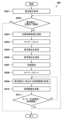
次に、図5のフローチャートを参照して、電池103の充電が行われる場合の制御処理について説明する。
Next, control processing when charging the
なお、図5の処理500は、電子機器100の充電制御部102が内部メモリ117に格納されたプログラムを実行することによって制御される。処理500は、接続部101にチャージャー300が接続されてPPS通信が開始されると開始される。
Note that the
ステップS501において、電圧検出部104は、電池103の電池電圧を取得する。電池電圧はアナログ電圧であるが、電圧検出部104の持つアナログデジタル変換機能によってデジタル値に変換される。変換されたデジタル値は、内部メモリ117に初期電池電圧として記憶される。
In step S501, the voltage detection unit 104 acquires the battery voltage of the
ステップS502において、充電制御部102は、電圧検出部104の情報に基づいて、電池103の電池電圧が充電完了閾値を上回っているか否かを判定する。電池103の電池電圧が充電完了閾値を上回っていると判定した場合、充電制御部102は、充電完了と判定し、電池103の充電を終了する。電池103の電池電圧が充電完了閾値を上回っていないと判定した場合、充電制御部102は、処理500をステップS503に進める。
In step S502, the charging
ステップS503において、充電制御部102は、充電累積時間を更新する。充電累積時間は、タイマー116により計測したPPS通信から次のPPS通信までの時間を順次加算していき、充電開始からの経過時間を累積した時間情報である。充電開始時には充電累積時間はゼロである。
In step S503, the charging
ステップS504において、充電制御部102は、タイマー116にリセット信号を送信する。これによりタイマー116の計測時間はリセットされる。
In step S504, charging
ステップS505において、充電制御部102は、チャージャー300に対する要求電圧を計算する。充電制御部102は、予め電池電圧に対する要求電圧のテーブルを内部メモリ117に記憶しておき、現在の電池電圧に対応する要求電圧を内部メモリ117から読み出す。テーブルとは、図4におけるVBUS電圧と電池電圧の関係を示したテーブルである。図4において、電池電圧の値が一意に決まれば、それに対応するVBUS電圧も一意に決まる。現在の電池電圧に対して一意的に決まるVBUS電圧の値が、要求すべき電圧である。このように、CCCV充電を行う際に従うべき充電カーブに基づいて電池電圧とVBUS電圧(=要求電圧)のテーブルを作成し、内部メモリ117に記憶しておくことで、内部メモリ117から現在の電池電圧に対応する要求電圧を読み出すことが可能になる。
In step S505, charging
なお、現在の電池電圧の取得方法としては、例えば、電圧検出部104によって再度電池電圧を検出した値を用いてもよい。また、これ以外の方法としては、ステップS501で取得した初期電池電圧と、ステップS503で更新された充電累積時間を用いて、現在の電池電圧の予測値(予測電池電圧)を計算してもよい。充電制御部102によって実施される充電カーブは図4で示したように既知であるので、初期電池電圧と充電累積時間が分かれば現在の電池電圧は予測可能である。
Note that as a method for obtaining the current battery voltage, for example, a value obtained by detecting the battery voltage again by the voltage detection unit 104 may be used. Alternatively, a predicted value of the current battery voltage (predicted battery voltage) may be calculated using the initial battery voltage acquired in step S501 and the cumulative charging time updated in step S503. . Since the charging curve implemented by the charging
ステップS506において、通信制御部115は、接続部101を介してチャージャー300とPPS通信を行う。通信制御部115は、ステップS505において計算された要求電圧を充電制御部102から受信し、PPS通信にてチャージャー300に送信する。
In step S506, the
ステップS507において、充電制御部102は、チャージャー300から供給される電力を受け取り、電池103の充電を行う。
In step S507, charging
ステップS508において、充電制御部102は、タイマー116による計時を開始させる。タイマー116は、PPS通信から次のPPS通信までの時間を計測するために用いられる。
In step S508, the charging
ステップS509において、充電制御部102は、現在の電池電圧に相当する時間閾値を内部メモリ117から読み出す。なお、現在の電池電圧の取得方法については、ステップS505で説明した通りである。
In step S509, charging
ここで、現在の電池電圧と時間閾値のテーブルについて説明する。実施形態1では、充電カーブの勾配に応じて以下のようにPPSの通信間隔を決定する。 Here, a table of current battery voltages and time thresholds will be explained. In the first embodiment, the PPS communication interval is determined as follows according to the slope of the charging curve.
電子機器100がCCCV充電時に従うべき充電カーブが既知であれば、現在の電池電圧を利用することで充電カーブにおける現在の位置が一意に決まり、さらに充電カーブの勾配も一意に決まる。したがって、設定すべきPPSの通信間隔も一意に決まり、この通信間隔でPPS通信を行うために時間閾値を設定する。例えば1秒間隔でPPS通信を行う場合には、時間閾値を1秒に設定すればよい。このテーブルについては、充電カーブの勾配に応じて時間閾値を変更することが可能である。例えば充電カーブの勾配が急峻になるときの電池電圧においては、時間閾値を小さくすることができる。これにより、勾配が急峻なところでは通信間隔を狭めることができる。ただし、PPSの規格を遵守するために、時間閾値は10秒以下の値に設定する必要がある。
If the charging curve that the
上述したように、現在の電池電圧に対する時間閾値のテーブルを定めることができる。図6は電池電圧に対する要求電圧および時間閾値のテーブルの一例を示している。電池を充電するために、要求電圧は電池電圧よりも大きな値とする。要求電圧は電池電圧の値に応じて変化し、1つのテーブルにおいては、電池電圧に対して要求電圧が一意に定まる。また、充電カーブの勾配が急峻な充電開始付近であって電池電圧が低いときには、時間閾値は0.1秒といった小さな値とし、通信間隔を狭めることができる。反対に、充電カーブの勾配が緩やかな充電終了付近であって電池電圧が高いときには、時間閾値は5秒といった大きな値とし、通信間隔を広げることができる。いずれの場合も、時間閾値は10秒以下の値に設定される。 As mentioned above, a table of time thresholds for current battery voltage can be defined. FIG. 6 shows an example of a table of required voltages and time thresholds for battery voltages. In order to charge the battery, the required voltage is greater than the battery voltage. The required voltage changes depending on the value of the battery voltage, and in one table, the required voltage is uniquely determined with respect to the battery voltage. Furthermore, when the charging curve is near the start of charging with a steep slope and the battery voltage is low, the time threshold can be set to a small value such as 0.1 seconds to narrow the communication interval. On the other hand, when the charging curve is near the end of charging and the slope is gentle and the battery voltage is high, the time threshold can be set to a large value such as 5 seconds to widen the communication interval. In either case, the time threshold is set to a value of 10 seconds or less.
図5の説明に戻り、ステップS510において、充電制御部102は、ステップS509で読み出した値に基づいて時間閾値を更新する。
Returning to the description of FIG. 5, in step S510, the charging
ステップS511において、充電制御部102は、タイマー116で計測した時間が時間閾値を超えたか否かを判定する。タイマー116で計測した時間が時間閾値を超えていないと判定された場合、充電制御部102は、処理500をステップS509に戻す。タイマー116で計測した時間が時間閾値を超えたと判定された場合、充電制御部102は、処理500をステップS502に戻す。
In step S511, the charging
図7は、電池103の充電が行われる場合の制御処理のタイムチャートを示している。図7(a)は、通信間隔が狭いCC充電が行われる場合のタイムチャートを示している。図7(b)は、通信間隔が広いCV充電が行われる場合のタイムチャートを示している。
FIG. 7 shows a time chart of control processing when the
図7(a)において、チャージャー300から供給されるVBUS電圧によって充電が行われ、電池電圧が上昇していくとき、タイマー116による計測時間が徐々に増加していく。所定の時間が経過すると、タイマー計測時間が時間閾値を上回り、充電制御部102はタイマー計測時間が時間閾値を超えたと判定する。時間閾値を超えたときにPPS通信が行われ、通信制御部115が要求電圧をチャージャー300に通知することで、VBUS電圧が更新される。このとき、タイマー116はリセットされ、再びゼロから計測を開始する。充電累積時間はタイマー116による計測時間を順次加算していくため、単調増加を続ける。また、時間閾値は電池電圧に基づいて計算される。図7(a)では時間閾値が一定となっているが、電池電圧が変化して充電カーブにおける勾配が変わると、時間閾値も更新される。
In FIG. 7A, charging is performed by the VBUS voltage supplied from the
図7(b)は、時間閾値がより大きな値に更新されたCV充電期間中のタイムチャートである。この場合には充電カーブの勾配も緩やかになる。図7(b)では、時間閾値がより大きな値に更新されているため、タイマー計測時間が時間閾値を上回るまでの時間は図7(a)のCC充電時よりも長くなる。充電制御部102により時間閾値を超えたと判定された後は、PPS通信が行われてVBUS電圧が更新され、タイマー116はリセットされてゼロから計測を再開する。
FIG. 7(b) is a time chart during the CV charging period in which the time threshold value is updated to a larger value. In this case, the slope of the charging curve also becomes gentle. In FIG. 7(b), since the time threshold value has been updated to a larger value, the time until the timer measurement time exceeds the time threshold value is longer than during CC charging in FIG. 7(a). After the charging
このように、実施形態1によれば、電池103の充電を開始したときの電池電圧と電池103の充電を開始してからの累積時間とに基づいてPPSの通信間隔を可変に制御することで、PPSによるCCCV充電における充電時間を短縮することが可能となる。
As described above, according to the first embodiment, the PPS communication interval is variably controlled based on the battery voltage when charging of the
[実施形態2]
次に、図8および図9を参照して、電池103の充電が行われる場合の制御処理について説明する。実施形態2では、図5の処理500に処理800が追加された実施形態である。処理800は、電池103の情報に応じて電池電圧に対する要求電圧および時間閾値のテーブルを選択する処理、予測電池電圧と現在の電池電圧の差分が大きい場合に要求電圧の計算方法を変更する処理を含む。
[Embodiment 2]
Next, control processing when the
図8の処理800は、図5のステップS502で充電制御部102が電池103の電池電圧が充電完了閾値を上回っていないと判定した場合に行われる。
まず、実施形態2におけるテーブル選択処理について説明する。実施形態1で説明したように、充電制御部102は内部メモリ117に格納された電池電圧に対する要求電圧のテーブルと、電池電圧に対する時間閾値のテーブルを参照して要求電圧、時間閾値を決定する。これは、電子機器100としてCCCV充電を行う際に従うべき充電カーブが既知である場合に、電池電圧の値が一意に決まれば、要求電圧も一意に決まり、充電カーブの勾配も一意に決まり、時間閾値も一意に決まることに基づいている。しかし、実際のCCCV充電を行うときの充電カーブは必ずしも一定ではない。例えば劣化した電池では劣化していない電池に比べて容量値が少なくなり、同じ容量で比較したときの電池電圧は小さくなる。これにより、充電カーブは変化する。そのため電池電圧に対する要求電圧のテーブル、および時間閾値のテーブルを一種類に限定するのではなく、電池の劣化度合いに応じて複数のテーブルを内部メモリ117に記憶しておけば、より適切なテーブルを選択することができる。テーブルの選択基準としては、電池の劣化度合いを定期的な電池電圧取得により検出し、劣化電池であると判定された場合には劣化電池用のテーブルを用いて電池103の充電を行えばよい。なお、テーブルの選択は充電開始時に行えばよいが、途中で劣化電池になる可能性も考慮して、定期的にテーブルを再選択するようにしてもよい。
First, table selection processing in the second embodiment will be explained. As described in the first embodiment, the charging
次に、図8のフローチャートを参照して、CC充電が行われる場合の制御処理について説明を行う。なお、図8の処理800は、図5のステップS502において充電制御部102が電池103の電池電圧が充電完了閾値を上回っていないと判定した場合に行われる。
Next, control processing when CC charging is performed will be explained with reference to the flowchart of FIG. 8. Note that processing 800 in FIG. 8 is performed when the charging
ステップS801において、充電制御部102は、電池103の劣化度取得タイミングであるか否かを判定する。劣化度の取得は充電開始時と、予め設定した所定のタイミングで行われる。所定のタイミングとは、例えばCC充電からCV充電への切り替えが行われた場合である。充電制御部102は、劣化度取得タイミングであると判定した場合には処理800をステップS802に進め、劣化度取得タイミングではないと判定した場合には処理800を終了してステップS503に進める。
In step S801, the charging
ステップS802において、充電制御部102は、電池103の劣化度を取得する。劣化度の取得方法として、電池103が劣化度の情報を持ち、電池103との通信が可能であれば、充電制御部102は電池103と通信を行い、劣化度情報を取得する。電池103が劣化度情報を持たない場合には、電圧検出部104と電流検出部118を用いて電池103から出力される電力の電圧値および電流値を検出することにより電池103の内部抵抗を計算してもよい。劣化した電池は内部抵抗が大きくなるため、計算した内部抵抗値から劣化度を判定することが可能である。
In step S802, the charging
ステップS803~S809において、充電制御部102は、電池103の劣化度がどの範囲にあるかを判定し、判定した範囲に応じたテーブルを選択する。
In steps S803 to S809, the charging
ステップS803において、充電制御部102は、電池103の劣化度が劣化閾値1より小さいか否かを判定する。電池103の劣化度が劣化閾値1より小さいと判定された場合、充電制御部102は、処理800をステップS806に進める。電池103の劣化度が劣化閾値1より小さいと判定されなかった場合、充電制御部102は、処理800をステップS804に進める。
In step S803, the charging
ステップS804において、充電制御部102は、電池の劣化度が劣化閾値2より小さいか否かを判定する。電池103の劣化度が劣化閾値2より小さいと判定された場合、充電制御部102は、処理800をステップSS807に進める。電池103の劣化度が劣化閾値2より小さいと判定されなかった場合、充電制御部102は、処理800をステップS805に進める。
In step S804, the charging
ステップS805において、充電制御部102は、電池の劣化度が劣化閾値3より小さいか否かを判定する。電池103の劣化度が劣化閾値3より小さいと判定された場合、充電制御部102は、処理800をステップS808に進める。電池103の劣化度が劣化閾値3より小さいと判定されなかった場合、充電制御部102は、処理800をステップS809に進める。
In step S805, the charging
ステップS806において、充電制御部102は、電池電圧に対する要求電圧テーブル1、電池電圧に対する時間閾値テーブル1を内部メモリ117から読み出し、処理800をステップS503に進める。
In step S806, the charging
ステップS807において、充電制御部102は、電池電圧に対する要求電圧テーブル2、電池電圧に対する時間閾値テーブル2を内部メモリ117から読み出し、処理800をステップS503に進める。
In step S807, the charging
ステップS808において、充電制御部102は、電池電圧に対する要求電圧テーブル3、電池電圧に対する時間閾値テーブル3を内部メモリ117から読み出し、処理800をステップS503に進める。
In step S808, the charging
ステップS809において、充電制御部102は、電池電圧に対する要求電圧テーブル4、電池電圧に対する時間閾値テーブル4を内部メモリ117から読み出し、処理800をステップS503に進める。
In step S809, the charging
ステップS503以降の処理500では、選択されたテーブルが使用される。
In the
このように複数のテーブルを記憶しておき、電池情報に応じて適切なテーブルを選択することで、実際の充電カーブに即した無駄なく高速な充電が可能になる。 By storing a plurality of tables in this way and selecting an appropriate table according to the battery information, it is possible to perform high-speed charging without waste in accordance with the actual charging curve.
なお、実施形態2ではテーブル選択の根拠となる電池情報として劣化度の例を説明したが、例えば電池103の内部抵抗、電池電圧、電池電流など、他の電池情報に基づいてテーブル選択を行ってもよい。 In the second embodiment, an example of the degree of deterioration was explained as the battery information that is the basis for table selection. Good too.
次に、実施形態2における予測電池電圧と現在の電池電圧の比較処理について説明する。 Next, a comparison process between the predicted battery voltage and the current battery voltage in the second embodiment will be described.
実施形態1で説明したように現在の電池電圧が分かれば理想的な充電カーブにおける位置が一意に決まる。しかしながら、実際の充電カーブはチャージャー300から供給される電流値によって変化し、電流値はチャージャー300の供給能力によって変化する。供給能力が変化する要因としては、例えばチャージャー300の温度変化による場合、チャージャー300が複数の機器に対して電力を供給可能な場合には電子機器100とは異なる機器の負荷電流の変化による場合などが考えられる。実施形態2では、実際の充電カーブが理想的な充電カーブから外れていることを検出するために、所定のタイミングで電池電圧を取得する。所定のタイミングとは、PPS通信の通信間隔以上のタイミングである。所定のタイミングで取得した電池電圧を予測電池電圧と比較し、予測電池電圧との差分が大きい場合には取得した電池電圧を初期電池電圧として更新し、充電累積時間もリセットする。そして、所定のタイミングで取得した電池電圧を充電開始タイミングとして電池103の充電を再開する。これにより、チャージャー300の供給能力が変化し実際の充電カーブが理想的な充電カーブから外れていた場合でも、定期的に現在の電池電圧を取得して正しい要求電圧に修正できる。なお、予測電池電圧の取得方法は、実施形態1の図5のステップS505で説明した通りである。
As explained in the first embodiment, if the current battery voltage is known, the position on the ideal charging curve is uniquely determined. However, the actual charging curve changes depending on the current value supplied from the
次に、図9のフローチャートを参照して、実施形態2における予測電池電圧と現在の電池電圧の比較処理について説明する。なお、図9の処理900は、図5のステップS504の後に行われる。 Next, with reference to the flowchart of FIG. 9, a comparison process between the predicted battery voltage and the current battery voltage in the second embodiment will be described. Note that processing 900 in FIG. 9 is performed after step S504 in FIG. 5.
ステップS901において、充電制御部102は、電池103の電圧取得タイミングであるか否かを判定する。電池103の電圧取得は、前述のようにPPS通信の通信間隔以上の所定のタイミングで実施すればよい。例えば、タイマー116により前回の電池電圧取得からの計測時間が閾値を超えているか否かを判定することも可能である。電池103の電圧取得タイミングであると判定された場合、充電制御部102は、処理900をステップS903に進める。電池103の電圧取得タイミングがではないと判定された場合、充電制御部102は、処理900を終了して図5のステップS505に進める。
In step S901, the charging
ステップS902において、電圧検出部104は、電池電圧を取得する。 In step S902, the voltage detection unit 104 acquires the battery voltage.
ステップS903において、充電制御部102は、ステップS903で取得した現在の電池電圧と予測電池電圧との差分を計算し、計算された差分が閾値より大きいか否かを判定する。計算された差分が閾値より大きい場合、充電制御部102は、現在の電池電圧が予測電池電圧から大きく外れていると判定し、処理900をステップS904に進める。計算された差分が閾値以下である場合、充電制御部102は、処理900を終了して図5の処理500におけるステップS505に進める。
In step S903, the charging
ステップS904において、充電制御部102は、充電累積時間をリセットする。
In step S904, the charging
ステップS905において、充電制御部102は、初期電池電圧の値をステップS902で取得した電池電圧に更新する。
In step S905, the charging
ステップS904~S905の処理により、ステップS902で取得した電池電圧が新たな充電開始タイミングとなり、現在の電池電圧と予測電池電圧との差分を修正することができる。 Through the processing in steps S904 and S905, the battery voltage acquired in step S902 becomes the new charging start timing, and the difference between the current battery voltage and the predicted battery voltage can be corrected.
なお、実施形態2では、チャージャー300の供給能力に変化がないか否かを確認するために、図9において電池電圧と予測電池電圧の差分を計算したが、他の方法を用いてもよい。例えば、電流検出部118を用いて所定のタイミングで充電電流を取得し、電流変化量検出部119を用いて充電電流の変化量を取得することも可能である。電流値の変化量が閾値以上である場合には、電流の変化量に応じて参照しているテーブルを補正するか、もしくは予め補正されたテーブルを内部メモリ117に記憶しておき、参照するテーブルを変更するようにしてもよい。
Note that in the second embodiment, the difference between the battery voltage and the predicted battery voltage is calculated in FIG. 9 in order to confirm whether there is any change in the supply capacity of the
実施形態2によれば、電池103の劣化度に応じて適切なテーブルを選択し、予測電池電圧と現在の電池電圧の比較に応じて要求電圧を修正することで、PPSによるCCCV充電において実際の充電カーブに基づく無駄のない高速なCCCV充電が可能になる。
According to the second embodiment, by selecting an appropriate table according to the degree of deterioration of the
[実施形態3]
次に、図10のフローチャートを参照して、実施形態3における電子機器100の制御処理について説明する。
[Embodiment 3]
Next, with reference to the flowchart of FIG. 10, control processing of the
実施形態1では現在の電池電圧に対応する時間閾値を読み出すことでPPSの通信間隔を決定していた。これに対して、実施形態3では、電池電圧の変化量が小さくなったことが検出された場合はPPS規格で定められた通信間隔よりも短い時間でPPS通信を行う。 In the first embodiment, the PPS communication interval is determined by reading the time threshold corresponding to the current battery voltage. On the other hand, in the third embodiment, when it is detected that the amount of change in battery voltage has become small, PPS communication is performed in a time shorter than the communication interval defined by the PPS standard.
ステップS1001~S1007は、図5の処理500におけるステップS501~S508と一部を除いて同様であるため、それらの説明を省略する。ステップS1001~S1007とステップS501~S508との違いとは、図5の処理500におけるステップS503で行っていた充電累積時間の更新を、実施形態3では実施しないことである。実施形態3では、PPS通信ごとに電池電圧を取得し、充電累積時間を用いた予測電池電圧を計算しないため、充電累積時間は不要となる。
Steps S1001 to S1007 are the same as steps S501 to S508 in
ステップS1008において、充電制御部102は、CC充電期間かCV充電期間かを判定し、CC充電期間であると判定した場合は、処理1000をステップS1009に進め、CV充電期間であると判定した場合は、処理1000をステップS811に進める。実施形態3では、CC充電期間中は電池電圧変化量からPPSの通信間隔を決定し、CV充電期間中はPPS規格で定められた通信間隔(10秒)でPPS通信を行う。このため、ステップS1008にてCC充電期間かCV充電期間かの判定を行っている。
In step S1008, the charging
ステップS1009において、電圧変化量検出部114は、電池電圧変化量を計算する。電圧変化量検出部114は、電圧検出部104で連続的に取得している電池電圧を、時間で微分した値を計算して電池電圧変化量を求める。 In step S1009, the voltage change amount detection unit 114 calculates the battery voltage change amount. The voltage change amount detection unit 114 calculates a value obtained by differentiating the battery voltage that is continuously acquired by the voltage detection unit 104 with respect to time to obtain the battery voltage change amount.
ステップS1010において、充電制御部102は、ステップS1009で計算した電池電圧変化量が所定値である電圧変化閾値より小さいか否かを判定する。ステップS1009で計算した電池電圧変化量が電圧変化閾値より小さいと判定された場合、充電制御部102は、処理1000をステップS1002に戻す。ステップS1009で計算した電池電圧変化量が電圧変化閾値より小さいと判定されなかった場合、充電制御部102は、処理1000をステップS1011に進める。
In step S1010, charging
ステップS1011において、充電制御部102は、タイマー116で計測した時間が時間閾値(10秒)を超えたか否かを判定する。タイマー116で計測した時間が10秒を超えていないと判定された場合、充電制御部102は、処理1000をステップS1008に戻す。タイマー116で計測した時間が10秒を超えたと判定された場合、充電制御部102は、処理1000をステップS1002に戻す。
In step S1011, the charging
図11は、CCCV充電が行われる場合の動作を示すタイムチャートである。図11(a)は、CC充電が行われる場合のタイムチャートを示している。図11(b)は、CV充電が行われる場合のタイムチャートを示している。 FIG. 11 is a time chart showing the operation when CCCV charging is performed. FIG. 11(a) shows a time chart when CC charging is performed. FIG. 11(b) shows a time chart when CV charging is performed.
図11(a)に示すCC充電期間中は、チャージャー300から供給されるVBUS電圧によって充電が行われ、電池電圧が上昇していくと、電池電圧の変化量はVBUS電圧の切り替え直後から時間が経過するほど小さくなる。この理由は、VBUS電圧と電池電圧との電位差が小さくなり電池電圧が飽和し始めるからである。そこで、実施形態3では、CC充電期間中は電池電圧の変化量からPPSの通信間隔を決定する。詳しくは、CC充電期間において、電池電圧の変化量が閾値を上回っている場合はPPS規格で定められた間隔でPPS通信を行い、電池電圧の変化量が閾値を上回っていない場合はPPS規格で定められた通信間隔よりも短い通信間隔でPPS通信を行う。
During the CC charging period shown in FIG. 11(a), charging is performed by the VBUS voltage supplied from the
図11(b)に示すCV充電期間中はVBUS電圧の切り替え直後から電池電圧の勾配が緩いため、電圧変化が小さいことを検出してPPSの通信間隔を決定することは難しい。また、CV充電期間中は10秒ごとにPPS通信を実施したとしても、充電時間が大きく延びることはない。そのため、CV充電期間中におけるPPSの通信間隔は、PPS規格で定められた10秒とする。 During the CV charging period shown in FIG. 11(b), the slope of the battery voltage is gentle immediately after switching the VBUS voltage, so it is difficult to detect that the voltage change is small and determine the PPS communication interval. Further, even if PPS communication is performed every 10 seconds during the CV charging period, the charging time will not be significantly extended. Therefore, the PPS communication interval during the CV charging period is set to 10 seconds as defined by the PPS standard.
実施形態3によれば、CC充電期間中は電池電圧の変化量からPPSの通信間隔を決定することで、CCCV充電における充電時間を短縮することが可能となる。 According to the third embodiment, by determining the PPS communication interval from the amount of change in battery voltage during the CC charging period, it is possible to shorten the charging time in CCCV charging.
[実施形態4]
実施形態1~3で説明した様々な機能、処理または方法は、パーソナルコンピュータ、マイクロコンピュータ、CPU(Central Processing Unit)またはプロセッサがプログラムを実行することによって実現することもできる。以下、実施形態4では、パーソナルコンピュータ、マイクロコンピュータ、CPU(Central Processing Unit)またはプロセッサを「コンピュータX」と呼ぶ。また、実施形態4では、コンピュータXを制御するためのプログラムであって、実施形態1~3で説明した様々な機能、処理または方法を実現するためのプログラムを「プログラムY」と呼ぶ。
[Embodiment 4]
The various functions, processes, or methods described in
実施形態1~3で説明した様々な機能、処理または方法は、コンピュータXがプログラムYを実行することによって実現される。この場合において、プログラムYは、コンピュータ読み取り可能な記憶媒体を介してコンピュータXに供給される。実施形態4におけるコンピュータ読み取り可能な記憶媒体は、ハードディスク装置、磁気記憶装置、光記憶装置、光磁気記憶装置、メモリカード、揮発性メモリ、不揮発性メモリなどの少なくとも1つを含む。実施形態4におけるコンピュータ読み取り可能な記憶媒体は、non-transitoryな記憶媒体である。
The various functions, processes, or methods described in
100…電子機器、101…接続部、102…充電制御部、103…電池、104…電圧検出部、114…電圧変化量検出部、115…通信制御部、116…タイマー、117…内部メモリ、118…電流検出部、119…電流変化量検出部
DESCRIPTION OF
Claims (11)
外部機器と通信する通信手段と、
前記外部機器から供給された電力を受け取る受電手段と、
前記受電手段が前記外部機器から受け取った電力により電池を充電する充電手段と、
前記充電手段により前記電池を充電する場合に、前記電子機器が前記外部機器に電力を要求するための所定の通信を行うように、前記通信手段を制御する制御手段とを有し、
前記充電手段により前記電池を充電する場合に、前記制御手段は、前記充電手段により前記電池の充電を開始してから前記電池の電圧が所定の電圧となるまでの、前記所定の通信を行う間隔が、前記電池の電圧が前記所定の電圧となった後の、前記所定の通信を行う間隔よりも短くなるように、前記通信手段を制御することを特徴とする電子機器。 An electronic device,
a communication means for communicating with an external device;
power receiving means for receiving power supplied from the external device;
Charging means for charging a battery with the power received by the power receiving means from the external device;
a control means for controlling the communication means so that the electronic device performs predetermined communication for requesting power from the external device when the battery is charged by the charging means;
When charging the battery by the charging means, the control means controls an interval for performing the predetermined communication from when the charging means starts charging the battery until the voltage of the battery reaches a predetermined voltage. The electronic device is characterized in that the communication means is controlled so as to be shorter than the interval at which the predetermined communication is performed after the voltage of the battery reaches the predetermined voltage.
前記制御手段は、前記電圧検出手段により検出された電圧または前記充電手段により電池の充電を開始してからの経過時間に応じて予測された電圧に基づいて前記間隔を決定することを特徴とする請求項1に記載の電子機器。 further comprising voltage detection means for detecting the voltage of the battery,
The control means determines the interval based on the voltage detected by the voltage detection means or the voltage predicted according to the elapsed time after the charging means starts charging the battery. The electronic device according to claim 1.
前記制御手段は、前記定電流による充電中の前記間隔を、前記定電圧による充電中の前記間隔よりも短くするように、前記通信手段を制御することを特徴とする請求項1から3のいずれか1項に記載の電子機器。 The charging means starts charging the battery with constant current, and then switches to charging with constant voltage,
4. The control means controls the communication means so that the interval during charging with the constant current is shorter than the interval during charging with the constant voltage . The electronic device according to any one of the items.
外部機器と通信する通信手段と、 a communication means for communicating with an external device;
前記外部機器から供給された電力を受け取る受電手段と、 power receiving means for receiving power supplied from the external device;
前記受電手段が前記外部機器から受け取った電力により電池を充電する充電手段と、 Charging means for charging a battery with the power received by the power receiving means from the external device;
前記充電手段により前記電池を充電する場合に、前記電子機器が前記外部機器に電力を要求するための所定の通信を行うように、前記通信手段を制御する制御手段とを有し、 a control means for controlling the communication means so that the electronic device performs predetermined communication for requesting power from the external device when the battery is charged by the charging means;
前記充電手段により前記電池の充電を開始してからの第1の期間における前記電池の電圧の時間変化に対応した充電カーブの勾配が、前記第1の期間の後の第2の期間における前記充電カーブの勾配よりも急である場合に、前記制御手段は、前記第1の期間において前記所定の通信を行う間隔が、前記第2の期間において前記所定の通信を行う間隔よりも短くなるように、前記通信手段を制御することを特徴とする電子機器。 The slope of the charging curve corresponding to the time change in the voltage of the battery in the first period after the charging means starts charging the battery is the charging curve in the second period after the first period. If the gradient of the curve is steeper than the slope of the curve, the control means may control the control means to make the interval at which the predetermined communication is performed in the first period shorter than the interval at which the predetermined communication is performed in the second period. , an electronic device that controls the communication means.
外部機器と通信する通信手段と、
前記外部機器から供給された電力を受け取る受電手段と、
前記受電手段が前記外部機器から受け取った電力により電池を充電する充電手段と、
前記充電手段により前記電池を充電する場合に、前記電子機器が前記外部機器に電力を要求するための所定の通信を行うように、前記通信手段を制御する制御手段とを有し、
前記充電手段により前記電池を充電する場合に、前記制御手段は、前記電池の電圧の変化量が所定値を上回っている場合は、第1の間隔で前記所定の通信を行い、前記電池の電圧の変化量が前記所定値を上回っていない場合は、前記第1の間隔よりも短い第2の間隔で前記所定の通信を行うように前記通信手段を制御することを特徴とする電子機器。 An electronic device,
a communication means for communicating with an external device;
power receiving means for receiving power supplied from the external device;
Charging means for charging a battery with the power received by the power receiving means from the external device;
a control means for controlling the communication means so that the electronic device performs predetermined communication for requesting power from the external device when the battery is charged by the charging means;
When charging the battery by the charging means, if the amount of change in the voltage of the battery exceeds a predetermined value, the control means performs the predetermined communication at a first interval to adjust the voltage of the battery. If the amount of change in the electronic device does not exceed the predetermined value, the communication means is controlled to perform the predetermined communication at a second interval shorter than the first interval. .
前記電子機器は、
外部機器と通信する通信手段と、
前記外部機器から供給された電力を受け取る受電手段と、
前記受電手段が前記外部機器から受け取った電力により電池を充電する充電手段とを有し、
前記制御方法は、
前記充電手段により前記電池を充電する場合に、前記電子機器が前記外部機器に電力を要求するための所定の通信を行うように、前記通信手段を制御するステップを有し、
前記充電手段により前記電池を充電する場合に、前記制御するステップでは、前記充電手段により前記電池の充電を開始してから前記電池の電圧が所定の電圧となるまでの、前記所定の通信を行う間隔が、前記電池の電圧が前記所定の電圧となった後の、前記所定の通信を行う間隔よりも短くなるように、前記通信手段を制御することを特徴とする制御方法。 A method for controlling electronic equipment, the method comprising:
The electronic device is
a communication means for communicating with an external device;
power receiving means for receiving power supplied from the external device;
The power receiving means includes a charging means for charging a battery with the power received from the external device,
The control method includes:
controlling the communication means so that the electronic device performs predetermined communication for requesting power from the external device when the battery is charged by the charging means;
When the battery is charged by the charging means, in the controlling step, the predetermined communication is performed from when the charging means starts charging the battery until the voltage of the battery reaches a predetermined voltage. A control method characterized in that the communication means is controlled so that the interval is shorter than the interval at which the predetermined communication is performed after the voltage of the battery reaches the predetermined voltage.
前記電子機器は、 The electronic device is
外部機器と通信する通信手段と、 a communication means for communicating with an external device;
前記外部機器から供給された電力を受け取る受電手段と、 power receiving means for receiving power supplied from the external device;
前記受電手段が前記外部機器から受け取った電力により電池を充電する充電手段とを有し、 The power receiving means includes a charging means for charging a battery with the power received from the external device,
前記制御方法は、 The control method includes:
前記充電手段により前記電池を充電する場合に、前記電子機器が前記外部機器に電力を要求するための所定の通信を行うように、前記通信手段を制御するステップを有し、 controlling the communication means so that the electronic device performs predetermined communication for requesting power from the external device when the battery is charged by the charging means;
前記充電手段により前記電池の充電を開始してからの第1の期間における前記電池の電圧の時間変化に対応した充電カーブの勾配が、前記第1の期間の後の第2の期間における前記充電カーブの勾配よりも急である場合に、前記制御するステップでは、前記第1の期間において前記所定の通信を行う間隔が、前記第2の期間において前記所定の通信を行う間隔よりも短くなるように、前記通信手段を制御することを特徴とする制御方法。 The slope of the charging curve corresponding to the time change in the voltage of the battery in the first period after the charging means starts charging the battery is the charging curve in the second period after the first period. If the slope is steeper than the slope of the curve, in the controlling step, the interval at which the predetermined communication is performed in the first period is shorter than the interval at which the predetermined communication is performed in the second period. A control method characterized by controlling the communication means.
前記電子機器は、
外部機器と通信する通信手段と、
前記外部機器から供給された電力を受け取る受電手段と、
前記受電手段が前記外部機器から受け取った電力により電池を充電する充電手段とを有し、
前記制御方法は、
前記充電手段により前記電池を充電する場合に、前記電子機器が前記外部機器に電力を要求するための所定の通信を行うように、前記通信手段を制御するステップを有し、
前記充電手段により前記電池を充電する場合に、前記制御するステップでは、前記電池の電圧の変化量が所定値を上回っている場合は、第1の間隔で前記所定の通信を行い、前記電池の電圧の変化量が前記所定値を上回っていない場合は、前記第1の間隔よりも短い第2の間隔で前記所定の通信を行うように前記通信手段を制御することを特徴とする制御方法。 A method for controlling electronic equipment, the method comprising:
The electronic device is
a communication means for communicating with an external device;
power receiving means for receiving power supplied from the external device;
The power receiving means includes a charging means for charging a battery with the power received from the external device,
The control method includes:
controlling the communication means so that the electronic device performs predetermined communication for requesting power from the external device when the battery is charged by the charging means;
When charging the battery by the charging means, in the controlling step, if the amount of change in the voltage of the battery exceeds a predetermined value, the predetermined communication is performed at a first interval, and the voltage of the battery is increased. If the amount of change in voltage does not exceed the predetermined value, the communication means is controlled to perform the predetermined communication at a second interval shorter than the first interval. Method.
Priority Applications (4)
| Application Number | Priority Date | Filing Date | Title |
|---|---|---|---|
| JP2019217499A JP7370834B2 (en) | 2019-11-29 | 2019-11-29 | Electronic equipment and control methods |
| US17/103,356 US11539218B2 (en) | 2019-11-29 | 2020-11-24 | Electronic device and control method |
| EP20209969.3A EP3829021A1 (en) | 2019-11-29 | 2020-11-26 | Electronic device and control method |
| CN202011364132.4A CN112886653A (en) | 2019-11-29 | 2020-11-27 | Electronic apparatus and control method |
Applications Claiming Priority (1)
| Application Number | Priority Date | Filing Date | Title |
|---|---|---|---|
| JP2019217499A JP7370834B2 (en) | 2019-11-29 | 2019-11-29 | Electronic equipment and control methods |
Publications (3)
| Publication Number | Publication Date |
|---|---|
| JP2021087342A JP2021087342A (en) | 2021-06-03 |
| JP2021087342A5 JP2021087342A5 (en) | 2022-11-29 |
| JP7370834B2 true JP7370834B2 (en) | 2023-10-30 |
Family
ID=73598712
Family Applications (1)
| Application Number | Title | Priority Date | Filing Date |
|---|---|---|---|
| JP2019217499A Active JP7370834B2 (en) | 2019-11-29 | 2019-11-29 | Electronic equipment and control methods |
Country Status (4)
| Country | Link |
|---|---|
| US (1) | US11539218B2 (en) |
| EP (1) | EP3829021A1 (en) |
| JP (1) | JP7370834B2 (en) |
| CN (1) | CN112886653A (en) |
Families Citing this family (3)
| Publication number | Priority date | Publication date | Assignee | Title |
|---|---|---|---|---|
| US11829169B2 (en) * | 2020-05-14 | 2023-11-28 | Texas Instruments Incorporated | USB power delivery management |
| JP2022180709A (en) | 2021-05-25 | 2022-12-07 | 株式会社Jvcケンウッド | Comparator circuit and drive circuit |
| JP2023117859A (en) * | 2022-02-14 | 2023-08-24 | 株式会社マキタ | Charging adapter and charger |
Citations (3)
| Publication number | Priority date | Publication date | Assignee | Title |
|---|---|---|---|---|
| JP2015070777A (en) | 2013-10-01 | 2015-04-13 | パイオニア株式会社 | Power reception device, communication control method, computer program, and power supply device |
| JP2017174138A (en) | 2016-03-23 | 2017-09-28 | ローム株式会社 | Power supply device, power supply method, control circuit, ac adapter, and electronic apparatus |
| JP2018129915A (en) | 2017-02-07 | 2018-08-16 | 株式会社東芝 | Charger |
Family Cites Families (13)
| Publication number | Priority date | Publication date | Assignee | Title |
|---|---|---|---|---|
| US5557190A (en) * | 1994-02-28 | 1996-09-17 | Black & Decker Inc. | Battery recharging system with signal-to-noise responsive falling voltage slope charge termination |
| JP2004064885A (en) * | 2002-07-29 | 2004-02-26 | Omron Corp | Power supply management system using solar cell as power supply, and information apparatus using the same |
| JP4827613B2 (en) * | 2006-05-24 | 2011-11-30 | 株式会社ソニー・コンピュータエンタテインメント | TERMINAL DEVICE, BATTERY CHARGE CONTROL METHOD, AND GAME SYSTEM |
| US8274261B2 (en) | 2007-07-13 | 2012-09-25 | Black & Decker Inc. | Cell monitoring and balancing |
| JP5398160B2 (en) * | 2008-03-31 | 2014-01-29 | パナソニック株式会社 | Electronic device, charger, and electronic device charging system |
| JP6173057B2 (en) * | 2013-06-11 | 2017-08-02 | キヤノン株式会社 | Power supply apparatus, power supply method, program, and recording medium |
| JP6410476B2 (en) * | 2014-05-28 | 2018-10-24 | キヤノン株式会社 | ELECTRONIC DEVICE, ITS CONTROL METHOD, PROGRAM, AND POWER SUPPLY DEVICE |
| US9748782B1 (en) * | 2015-01-12 | 2017-08-29 | Google Inc. | Power adapter charging modification based on a feedback loop |
| CN104767260B (en) * | 2015-03-30 | 2017-04-05 | 华为技术有限公司 | Charger, terminal unit and charging system |
| JP7073048B2 (en) * | 2017-04-28 | 2022-05-23 | キヤノン株式会社 | Electronic devices, control methods and programs for electronic devices |
| US10680446B2 (en) * | 2017-08-25 | 2020-06-09 | Black & Decker Inc. | Battery pack charger system |
| CN109804542B (en) * | 2017-09-22 | 2021-06-11 | Oppo广东移动通信有限公司 | Power supply circuit, power supply device, and control method |
| EP3537567B1 (en) * | 2017-09-22 | 2023-02-15 | Guangdong Oppo Mobile Telecommunications Corp., Ltd. | Power supply circuit, power supply device, and control method |
-
2019
- 2019-11-29 JP JP2019217499A patent/JP7370834B2/en active Active
-
2020
- 2020-11-24 US US17/103,356 patent/US11539218B2/en active Active
- 2020-11-26 EP EP20209969.3A patent/EP3829021A1/en active Pending
- 2020-11-27 CN CN202011364132.4A patent/CN112886653A/en active Pending
Patent Citations (3)
| Publication number | Priority date | Publication date | Assignee | Title |
|---|---|---|---|---|
| JP2015070777A (en) | 2013-10-01 | 2015-04-13 | パイオニア株式会社 | Power reception device, communication control method, computer program, and power supply device |
| JP2017174138A (en) | 2016-03-23 | 2017-09-28 | ローム株式会社 | Power supply device, power supply method, control circuit, ac adapter, and electronic apparatus |
| JP2018129915A (en) | 2017-02-07 | 2018-08-16 | 株式会社東芝 | Charger |
Also Published As
| Publication number | Publication date |
|---|---|
| US20210167615A1 (en) | 2021-06-03 |
| EP3829021A1 (en) | 2021-06-02 |
| US11539218B2 (en) | 2022-12-27 |
| JP2021087342A (en) | 2021-06-03 |
| CN112886653A (en) | 2021-06-01 |
Similar Documents
| Publication | Publication Date | Title |
|---|---|---|
| JP7370834B2 (en) | Electronic equipment and control methods | |
| US10122908B2 (en) | Image pickup apparatus, lens apparatus, and image pickup system | |
| JP5789098B2 (en) | Focus detection apparatus and control method thereof | |
| JP2014013360A (en) | Imaging apparatus and control method thereof, and lens device and control method thereof | |
| US9871970B2 (en) | Imaging apparatus, control method, and storage medium storing program | |
| GB2555875A (en) | Accessory apparatus, image-capturing apparatus, control apparatus, lens apparatus, control method, computer program and storage medium storing computer | |
| US10666850B2 (en) | Imaging control apparatus | |
| JP2022025593A (en) | Electronic apparatus, control method and program | |
| JP2015119206A (en) | Image processing system, control method of the same and program | |
| US9069123B2 (en) | Lens device, drive method, recording medium, and image-capturing device | |
| US9560286B2 (en) | Image capturing apparatus and method for controlling the same | |
| US11184516B2 (en) | Imaging apparatus, control method for imaging apparatus, and storage medium | |
| JP7218137B2 (en) | Electronic device and its control method | |
| US10469733B2 (en) | Imaging apparatus, control method of imaging apparatus, and storage medium storing control program of imaging apparatus for controlling focus-related communications | |
| JP2016208648A (en) | Electronic apparatus, control method, and program | |
| JP2018022369A (en) | Electronic device, control method, program, and storage medium | |
| JP6032884B2 (en) | IMAGING DEVICE, IMAGING DEVICE CONTROL METHOD, PROGRAM | |
| US10348977B2 (en) | Image pickup apparatus calculating light-amount variation characteristic of light from object, control method therefor, and storage medium storing control program therefor | |
| US9736359B2 (en) | Image capturing apparatus and control method therefor | |
| JP2013015777A (en) | Imaging apparatus | |
| JP5956870B2 (en) | Imaging apparatus and control method thereof | |
| JP2012132957A (en) | Imaging apparatus and setup method therefor | |
| US20230269461A1 (en) | Image capture apparatus and control method thereof | |
| JP6188322B2 (en) | Automatic focusing apparatus, automatic focusing method, program, and imaging apparatus | |
| US20150156408A1 (en) | Imaging apparatus, method for controlling the same, and recording medium |
Legal Events
| Date | Code | Title | Description |
|---|---|---|---|
| RD01 | Notification of change of attorney |
Free format text: JAPANESE INTERMEDIATE CODE: A7421 Effective date: 20210103 |
|
| A521 | Request for written amendment filed |
Free format text: JAPANESE INTERMEDIATE CODE: A523 Effective date: 20210113 |
|
| A521 | Request for written amendment filed |
Free format text: JAPANESE INTERMEDIATE CODE: A523 Effective date: 20221118 |
|
| A621 | Written request for application examination |
Free format text: JAPANESE INTERMEDIATE CODE: A621 Effective date: 20221118 |
|
| A977 | Report on retrieval |
Free format text: JAPANESE INTERMEDIATE CODE: A971007 Effective date: 20230815 |
|
| TRDD | Decision of grant or rejection written | ||
| A01 | Written decision to grant a patent or to grant a registration (utility model) |
Free format text: JAPANESE INTERMEDIATE CODE: A01 Effective date: 20230919 |
|
| A61 | First payment of annual fees (during grant procedure) |
Free format text: JAPANESE INTERMEDIATE CODE: A61 Effective date: 20231018 |
|
| R151 | Written notification of patent or utility model registration |
Ref document number: 7370834 Country of ref document: JP Free format text: JAPANESE INTERMEDIATE CODE: R151 |