JP7370250B2 - Devices and methods for distant bipolar ablation - Google Patents
Devices and methods for distant bipolar ablation Download PDFInfo
- Publication number
- JP7370250B2 JP7370250B2 JP2019516289A JP2019516289A JP7370250B2 JP 7370250 B2 JP7370250 B2 JP 7370250B2 JP 2019516289 A JP2019516289 A JP 2019516289A JP 2019516289 A JP2019516289 A JP 2019516289A JP 7370250 B2 JP7370250 B2 JP 7370250B2
- Authority
- JP
- Japan
- Prior art keywords
- electrode
- balloon
- bladder
- electrodes
- circumferential
- Prior art date
- Legal status (The legal status is an assumption and is not a legal conclusion. Google has not performed a legal analysis and makes no representation as to the accuracy of the status listed.)
- Active
Links
Images


Classifications
-
- A—HUMAN NECESSITIES
- A61—MEDICAL OR VETERINARY SCIENCE; HYGIENE
- A61B—DIAGNOSIS; SURGERY; IDENTIFICATION
- A61B1/00—Instruments for performing medical examinations of the interior of cavities or tubes of the body by visual or photographical inspection, e.g. endoscopes; Illuminating arrangements therefor
- A61B1/307—Instruments for performing medical examinations of the interior of cavities or tubes of the body by visual or photographical inspection, e.g. endoscopes; Illuminating arrangements therefor for the urinary organs, e.g. urethroscopes, cystoscopes
-
- A—HUMAN NECESSITIES
- A61—MEDICAL OR VETERINARY SCIENCE; HYGIENE
- A61B—DIAGNOSIS; SURGERY; IDENTIFICATION
- A61B18/00—Surgical instruments, devices or methods for transferring non-mechanical forms of energy to or from the body
- A61B18/04—Surgical instruments, devices or methods for transferring non-mechanical forms of energy to or from the body by heating
- A61B18/12—Surgical instruments, devices or methods for transferring non-mechanical forms of energy to or from the body by heating by passing a current through the tissue to be heated, e.g. high-frequency current
- A61B18/14—Probes or electrodes therefor
- A61B18/1485—Probes or electrodes therefor having a short rigid shaft for accessing the inner body through natural openings
-
- A—HUMAN NECESSITIES
- A61—MEDICAL OR VETERINARY SCIENCE; HYGIENE
- A61B—DIAGNOSIS; SURGERY; IDENTIFICATION
- A61B18/00—Surgical instruments, devices or methods for transferring non-mechanical forms of energy to or from the body
- A61B18/04—Surgical instruments, devices or methods for transferring non-mechanical forms of energy to or from the body by heating
- A61B18/12—Surgical instruments, devices or methods for transferring non-mechanical forms of energy to or from the body by heating by passing a current through the tissue to be heated, e.g. high-frequency current
- A61B18/14—Probes or electrodes therefor
- A61B18/1492—Probes or electrodes therefor having a flexible, catheter-like structure, e.g. for heart ablation
-
- A—HUMAN NECESSITIES
- A61—MEDICAL OR VETERINARY SCIENCE; HYGIENE
- A61N—ELECTROTHERAPY; MAGNETOTHERAPY; RADIATION THERAPY; ULTRASOUND THERAPY
- A61N1/00—Electrotherapy; Circuits therefor
- A61N1/18—Applying electric currents by contact electrodes
- A61N1/32—Applying electric currents by contact electrodes alternating or intermittent currents
-
- A—HUMAN NECESSITIES
- A61—MEDICAL OR VETERINARY SCIENCE; HYGIENE
- A61B—DIAGNOSIS; SURGERY; IDENTIFICATION
- A61B18/00—Surgical instruments, devices or methods for transferring non-mechanical forms of energy to or from the body
- A61B18/18—Surgical instruments, devices or methods for transferring non-mechanical forms of energy to or from the body by applying electromagnetic radiation, e.g. microwaves
- A61B18/20—Surgical instruments, devices or methods for transferring non-mechanical forms of energy to or from the body by applying electromagnetic radiation, e.g. microwaves using laser
- A61B18/22—Surgical instruments, devices or methods for transferring non-mechanical forms of energy to or from the body by applying electromagnetic radiation, e.g. microwaves using laser the beam being directed along or through a flexible conduit, e.g. an optical fibre; Couplings or hand-pieces therefor
-
- A—HUMAN NECESSITIES
- A61—MEDICAL OR VETERINARY SCIENCE; HYGIENE
- A61B—DIAGNOSIS; SURGERY; IDENTIFICATION
- A61B18/00—Surgical instruments, devices or methods for transferring non-mechanical forms of energy to or from the body
- A61B2018/00053—Mechanical features of the instrument of device
- A61B2018/0016—Energy applicators arranged in a two- or three dimensional array
-
- A—HUMAN NECESSITIES
- A61—MEDICAL OR VETERINARY SCIENCE; HYGIENE
- A61B—DIAGNOSIS; SURGERY; IDENTIFICATION
- A61B18/00—Surgical instruments, devices or methods for transferring non-mechanical forms of energy to or from the body
- A61B2018/00053—Mechanical features of the instrument of device
- A61B2018/00166—Multiple lumina
-
- A—HUMAN NECESSITIES
- A61—MEDICAL OR VETERINARY SCIENCE; HYGIENE
- A61B—DIAGNOSIS; SURGERY; IDENTIFICATION
- A61B18/00—Surgical instruments, devices or methods for transferring non-mechanical forms of energy to or from the body
- A61B2018/00053—Mechanical features of the instrument of device
- A61B2018/00214—Expandable means emitting energy, e.g. by elements carried thereon
- A61B2018/0022—Balloons
- A61B2018/0025—Multiple balloons
- A61B2018/00255—Multiple balloons arranged one inside another
-
- A—HUMAN NECESSITIES
- A61—MEDICAL OR VETERINARY SCIENCE; HYGIENE
- A61B—DIAGNOSIS; SURGERY; IDENTIFICATION
- A61B18/00—Surgical instruments, devices or methods for transferring non-mechanical forms of energy to or from the body
- A61B2018/00053—Mechanical features of the instrument of device
- A61B2018/00214—Expandable means emitting energy, e.g. by elements carried thereon
- A61B2018/00267—Expandable means emitting energy, e.g. by elements carried thereon having a basket shaped structure
-
- A—HUMAN NECESSITIES
- A61—MEDICAL OR VETERINARY SCIENCE; HYGIENE
- A61B—DIAGNOSIS; SURGERY; IDENTIFICATION
- A61B18/00—Surgical instruments, devices or methods for transferring non-mechanical forms of energy to or from the body
- A61B2018/00315—Surgical instruments, devices or methods for transferring non-mechanical forms of energy to or from the body for treatment of particular body parts
- A61B2018/00482—Digestive system
- A61B2018/00494—Stomach, intestines or bowel
-
- A—HUMAN NECESSITIES
- A61—MEDICAL OR VETERINARY SCIENCE; HYGIENE
- A61B—DIAGNOSIS; SURGERY; IDENTIFICATION
- A61B18/00—Surgical instruments, devices or methods for transferring non-mechanical forms of energy to or from the body
- A61B2018/00315—Surgical instruments, devices or methods for transferring non-mechanical forms of energy to or from the body for treatment of particular body parts
- A61B2018/00505—Urinary tract
- A61B2018/00517—Urinary bladder or urethra
-
- A—HUMAN NECESSITIES
- A61—MEDICAL OR VETERINARY SCIENCE; HYGIENE
- A61B—DIAGNOSIS; SURGERY; IDENTIFICATION
- A61B18/00—Surgical instruments, devices or methods for transferring non-mechanical forms of energy to or from the body
- A61B2018/00315—Surgical instruments, devices or methods for transferring non-mechanical forms of energy to or from the body for treatment of particular body parts
- A61B2018/00559—Female reproductive organs
-
- A—HUMAN NECESSITIES
- A61—MEDICAL OR VETERINARY SCIENCE; HYGIENE
- A61B—DIAGNOSIS; SURGERY; IDENTIFICATION
- A61B18/00—Surgical instruments, devices or methods for transferring non-mechanical forms of energy to or from the body
- A61B2018/00571—Surgical instruments, devices or methods for transferring non-mechanical forms of energy to or from the body for achieving a particular surgical effect
- A61B2018/00577—Ablation
-
- A—HUMAN NECESSITIES
- A61—MEDICAL OR VETERINARY SCIENCE; HYGIENE
- A61B—DIAGNOSIS; SURGERY; IDENTIFICATION
- A61B18/00—Surgical instruments, devices or methods for transferring non-mechanical forms of energy to or from the body
- A61B2018/00636—Sensing and controlling the application of energy
- A61B2018/00773—Sensed parameters
- A61B2018/00875—Resistance or impedance
-
- A—HUMAN NECESSITIES
- A61—MEDICAL OR VETERINARY SCIENCE; HYGIENE
- A61B—DIAGNOSIS; SURGERY; IDENTIFICATION
- A61B18/00—Surgical instruments, devices or methods for transferring non-mechanical forms of energy to or from the body
- A61B2018/0091—Handpieces of the surgical instrument or device
- A61B2018/00916—Handpieces of the surgical instrument or device with means for switching or controlling the main function of the instrument or device
- A61B2018/0094—Types of switches or controllers
- A61B2018/00946—Types of switches or controllers slidable
-
- A—HUMAN NECESSITIES
- A61—MEDICAL OR VETERINARY SCIENCE; HYGIENE
- A61B—DIAGNOSIS; SURGERY; IDENTIFICATION
- A61B18/00—Surgical instruments, devices or methods for transferring non-mechanical forms of energy to or from the body
- A61B18/02—Surgical instruments, devices or methods for transferring non-mechanical forms of energy to or from the body by cooling, e.g. cryogenic techniques
- A61B2018/0212—Surgical instruments, devices or methods for transferring non-mechanical forms of energy to or from the body by cooling, e.g. cryogenic techniques using an instrument inserted into a body lumen, e.g. catheter
-
- A—HUMAN NECESSITIES
- A61—MEDICAL OR VETERINARY SCIENCE; HYGIENE
- A61B—DIAGNOSIS; SURGERY; IDENTIFICATION
- A61B18/00—Surgical instruments, devices or methods for transferring non-mechanical forms of energy to or from the body
- A61B18/04—Surgical instruments, devices or methods for transferring non-mechanical forms of energy to or from the body by heating
- A61B18/12—Surgical instruments, devices or methods for transferring non-mechanical forms of energy to or from the body by heating by passing a current through the tissue to be heated, e.g. high-frequency current
- A61B18/14—Probes or electrodes therefor
- A61B2018/1405—Electrodes having a specific shape
- A61B2018/144—Wire
-
- A—HUMAN NECESSITIES
- A61—MEDICAL OR VETERINARY SCIENCE; HYGIENE
- A61B—DIAGNOSIS; SURGERY; IDENTIFICATION
- A61B18/00—Surgical instruments, devices or methods for transferring non-mechanical forms of energy to or from the body
- A61B18/04—Surgical instruments, devices or methods for transferring non-mechanical forms of energy to or from the body by heating
- A61B18/12—Surgical instruments, devices or methods for transferring non-mechanical forms of energy to or from the body by heating by passing a current through the tissue to be heated, e.g. high-frequency current
- A61B18/14—Probes or electrodes therefor
- A61B2018/1465—Deformable electrodes
-
- A—HUMAN NECESSITIES
- A61—MEDICAL OR VETERINARY SCIENCE; HYGIENE
- A61B—DIAGNOSIS; SURGERY; IDENTIFICATION
- A61B18/00—Surgical instruments, devices or methods for transferring non-mechanical forms of energy to or from the body
- A61B18/04—Surgical instruments, devices or methods for transferring non-mechanical forms of energy to or from the body by heating
- A61B18/12—Surgical instruments, devices or methods for transferring non-mechanical forms of energy to or from the body by heating by passing a current through the tissue to be heated, e.g. high-frequency current
- A61B18/14—Probes or electrodes therefor
- A61B2018/1467—Probes or electrodes therefor using more than two electrodes on a single probe
-
- A—HUMAN NECESSITIES
- A61—MEDICAL OR VETERINARY SCIENCE; HYGIENE
- A61B—DIAGNOSIS; SURGERY; IDENTIFICATION
- A61B18/00—Surgical instruments, devices or methods for transferring non-mechanical forms of energy to or from the body
- A61B18/04—Surgical instruments, devices or methods for transferring non-mechanical forms of energy to or from the body by heating
- A61B18/12—Surgical instruments, devices or methods for transferring non-mechanical forms of energy to or from the body by heating by passing a current through the tissue to be heated, e.g. high-frequency current
- A61B18/14—Probes or electrodes therefor
- A61B2018/1475—Electrodes retractable in or deployable from a housing
-
- A—HUMAN NECESSITIES
- A61—MEDICAL OR VETERINARY SCIENCE; HYGIENE
- A61M—DEVICES FOR INTRODUCING MEDIA INTO, OR ONTO, THE BODY; DEVICES FOR TRANSDUCING BODY MEDIA OR FOR TAKING MEDIA FROM THE BODY; DEVICES FOR PRODUCING OR ENDING SLEEP OR STUPOR
- A61M2210/00—Anatomical parts of the body
- A61M2210/10—Trunk
- A61M2210/1078—Urinary tract
- A61M2210/1085—Bladder
Description
本願は、2016年6月6日に出願された米国仮出願第62/346,095号の利益を主張するものであり、該出願は、参照により本明細書中に援用される。 This application claims the benefit of U.S. Provisional Application No. 62/346,095, filed June 6, 2016, which is incorporated herein by reference.
本願の主題は、以下の同時係属中の特許出願の主題に関連している:2016年6月10日に出願されたPCT出願第PCT/IB2016/000953号、2016年6月10日に出願された米国特許出願第15/179,623号。これらの両方は、2015年6月11日に出願された米国仮特許出願第62/174,296号に対する優先権を主張するものであり、これらの出願は、参照により本明細書中に援用される。 The subject matter of this application relates to the subject matter of the following co-pending patent applications: PCT Application No. PCT/IB2016/000953, filed on June 10, 2016; U.S. patent application Ser. No. 15/179,623. Both of these claim priority to U.S. Provisional Patent Application No. 62/174,296, filed June 11, 2015, which are incorporated herein by reference. Ru.
本願の主題は、以下の同時係属中の特許出願の主題に関連している:2014年11月25日に出願されたPCT出願第PCT/IB2014/003083号(これは、2014年10月21日に出願された米国特許出願第14/519,933号の利益を主張するものであり、これは、2013年4月19日に出願されたPCT出願第PCT/IB2013/001203号の一部継続出願であり、これは、2012年4月22日に出願された米国仮出願第61/636,686号、2012年5月20日に出願された第61/649,334号の利益を主張するものであり、PCT出願第PCT/IB2014/003083号はまた、2013年11月26日に出願された米国仮出願第61/908,748号、2014年3月31日に出願された第61/972,441号の利益を主張するものであり(これらは、参照により本明細書中に援用される))、2015年1月22日に出願された米国特許出願第14/602,493号(これは、米国特許出願第14/519,933号の継続出願である)に関連しており、これらは、参照により本明細書中に援用される。 The subject matter of the present application relates to the subject matter of the following co-pending patent applications: PCT Application No. PCT/IB2014/003083, filed on November 25, 2014, claims the benefit of U.S. patent application Ser. , which claims the benefit of U.S. Provisional Application No. 61/636,686, filed April 22, 2012, and U.S. Provisional Application No. 61/649,334, filed May 20, 2012. and PCT Application No. PCT/IB2014/003083, which also includes U.S. Provisional Application No. 61/908,748, filed on November 26, 2013, and U.S. Provisional Application No. 61/972, filed on March 31, 2014. , 441 (which are incorporated herein by reference) and U.S. patent application Ser. , a continuation of U.S. patent application Ser. No. 14/519,933), which are incorporated herein by reference.
本開示は、特に、高周波(RF)エネルギーを用いる等の組織のアブレーションによる、医療処置のためのシステム、デバイス、および方法に関する。 The present disclosure particularly relates to systems, devices, and methods for medical treatment by tissue ablation, such as using radio frequency (RF) energy.
体内器官内のRFアブレーションは、以前に広く説明されており、当技術分野で周知である。広い表面積を伴う細長いまたは広範な損傷が所望される場合、RFエネルギーを利用する2つの主要な技術は、単極アブレーションおよび双極アブレーションである。
RF ablation within internal organs has been extensively described previously and is well known in the art. When elongated or extensive lesions with large surface areas are desired, the two main techniques that utilize RF energy are monopolar ablation and bipolar ablation.
単極アブレーションでは、治療電極は、損傷が作成される場所に設置され、電流は、組織を通して分散電極まで流れる。分散電極は、本分散電極にわたる電流密度が、いかなる損傷も形成することを防止するために十分に低いように、治療電極と比較して広い表面積を有する。本分散または「患者」または「接地」電極は、通常、大腿部または脇腹等の場所で患者の皮膚上に設置される。 In monopolar ablation, a treatment electrode is placed where the lesion is created and a current is passed through the tissue to the dispersive electrode. The dispersive electrode has a large surface area compared to the treatment electrode such that the current density across the dispersive electrode is sufficiently low to prevent any damage from forming. The distributed or "patient" or "ground" electrode is placed on the patient's skin, usually at a location such as the thigh or flank.
単極アブレーションを採用する内部器官アブレーション用途の実施例は、心房細動のための肺静脈のアイソレーションおよび肝臓等の軟組織中の腫瘍のアブレーションを含む。 Examples of internal organ ablation applications employing unipolar ablation include isolation of pulmonary veins for atrial fibrillation and ablation of tumors in soft tissues such as the liver.
本技術に関する問題は、分散電極と皮膚との間の接触が準最適であり、その場合、電流密度が増加し、ある場合には、重篤な熱傷および負傷と関連付けられる皮膚損傷が形成し得る、状況を含む。さらに悪いことには、接地電極の完全な接続解除は、異なるルートを通して電流を流れさせ得、重要器官を危険にさらし得る。単極アブレーションの別の不利点は、電極の縁においてより顕著である損傷の傾向である(「周縁効果」)。本効果は、比較的短い電極を使用することによって最小限にされることができるが、しかしながら、これは、より多くのワイヤを必要とする。 A problem with this technique is that the contact between the dispersive electrode and the skin is suboptimal, in which case the current density increases and in some cases can form skin lesions that are associated with severe burns and injuries. , including the situation. Even worse, complete disconnection of the ground electrode can cause current to flow through a different route, putting vital organs at risk. Another disadvantage of monopolar ablation is the tendency for damage to be more pronounced at the edges of the electrode ("periphery effect"). This effect can be minimized by using relatively short electrodes, however this requires more wire.
双極アブレーションでは、両方の電極は、「治療」電極と見なされ、通常、寸法および電気的性質がほぼ同じであり、相互に非常に近く、通常、1cm未満離れて設置される。電流は、組織を通して2つの電極の間に流れ、電極が同じであり、近接しているため、それらの間の組織は、多かれ少なかれ均一にアブレートされる。本構成では、線形損傷を達成するために、2つの別個のワイヤとともに、2つの隣接する電極が必要とされる(「線路」様構成)。 In bipolar ablation, both electrodes are considered "therapeutic" electrodes and are typically similar in size and electrical properties and are placed very close to each other, typically less than 1 cm apart. Current flows between the two electrodes through the tissue, and because the electrodes are the same and in close proximity, the tissue between them is ablated more or less uniformly. In this configuration, two adjacent electrodes are required along with two separate wires to achieve linear damage (a "track"-like configuration).
双極アブレーションを採用する内部器官アブレーション用途の実施例は、Medtronic PLC(Dublin, Ireland)から入手可能なBarrxデバイスを用いた食道のアブレーションを含む。 Examples of internal organ ablation applications employing bipolar ablation include ablation of the esophagus using the Barrx device available from Medtronic PLC (Dublin, Ireland).
本技術の利点は、高い正確度で損傷深度を制御する能力である。本技術に関する問題は主に、そのような電極によって治療されることができる限定された面積と関連付けられるため、広いアブレーション面積が所望される場合に、多数の電極が使用されなければならず、結果として多くのワイヤがそれらにつながり、デバイスの中の要素の直径を増加させる。 An advantage of this technique is the ability to control damage depth with high accuracy. The problems with this technique are primarily associated with the limited area that can be treated by such electrodes, so a large number of electrodes must be used when a large ablation area is desired, resulting in As more wires connect to them, they increase the diameter of the elements in the device.
それを通って延設する少数の電気ワイヤおよび挿入の薄型外形を有する、単純なデバイスを使用しながら、広い面積を有し、好ましくは、細長いものであるが、随意に、円形または縦長形等の広い表面積を有する、均質な損傷の安全、容易、および迅速な作成を可能にする様式で、中空器官内のアブレーションを可能にする、技術の必要性が残っている。
While using a simple device with a low profile profile of a few electrical wires and inserts extending through it, it has a large area, preferably elongated , but optionally circular or oblong etc. There remains a need for a technique that allows ablation within hollow organs in a manner that allows safe, easy, and rapid creation of homogeneous lesions with large surface areas.
上記で概説される必要性を解決するために、本開示は、本明細書では「遠距離双極」アブレーションと呼ばれる技法、および本技法を採用し得る具体的デバイス実施形態を説明する。 To address the needs outlined above, this disclosure describes a technique referred to herein as "distant bipolar" ablation, and specific device embodiments that may employ this technique.
遠距離双極技法は、単極電極を用いて生成されるものに類似する損傷を生成し得るように、標的器官内で相互から比較的大きい距離を置いて位置付けられる、実質的に等しい表面積を有する双極電極を利用してもよい。 Distance bipolar techniques have substantially equal surface areas positioned at a relatively large distance from each other within the target organ such that they can produce lesions similar to those produced using monopolar electrodes. Bipolar electrodes may also be used.
本開示に説明されるデバイス実施形態は、電極を標的器官壁に並置し得、典型的には、電極を伸張し、それらの圧潰および患者の身体からの除去を促進することが可能であり得る、拡張可能要素を備えてもよい。 Device embodiments described in this disclosure may juxtapose electrodes to the target organ wall and typically may be capable of stretching the electrodes to facilitate their collapse and removal from the patient's body. , may include an expandable element.
本開示の側面は、中空体内器官内の疾患を治療するためのデバイスを提供する。例示的デバイスは、遠位先端を有する、シャフトと、双極電極の少なくとも1つのセットと、折り畳みまたは圧縮位置から展開位置まで双極電極の少なくとも1つのセットを半径方向に拡張するように構成される、拡張可能部材とを備えてもよい。双極電極の各セットは、少なくとも1つの第1極性電極と、少なくとも1つの第2極性電極とを備えてもよい。展開位置では、各第1極性電極は、各第2極性電極と実質的に反対側の中空体内器官内の場所に位置付けられるように構成されてもよい。展開位置では、各電極対の間の距離は、電極のそれぞれの幅の少なくとも10倍であってもよい。 Aspects of the present disclosure provide devices for treating diseases within hollow body organs. An exemplary device includes a shaft having a distal tip, at least one set of bipolar electrodes, and configured to radially expand the at least one set of bipolar electrodes from a collapsed or compressed position to a deployed position. and an expandable member. Each set of bipolar electrodes may include at least one first polar electrode and at least one second polar electrode. In the deployed position, each first polarity electrode may be configured to be positioned at a location within the hollow body organ substantially opposite from each second polarity electrode. In the deployed position, the distance between each pair of electrodes may be at least 10 times the width of each of the electrodes.
双極電極の各セットのうちの少なくとも1つの第1極性電極の全組織接触面積は、双極電極の同一のセットのうちの少なくとも1つの第2極性電極の全表面積と実質的に等しくあり得る。 The total tissue contact area of at least one first polarity electrode of each set of bipolar electrodes can be substantially equal to the total tissue contact area of at least one second polarity electrode of the same set of bipolar electrodes.
本デバイスは、全体として中空体内器官を通した電気伝搬が低減されるように、中空体内器官の内壁の中で低減した電気伝搬を有する、電気的にアイソレートされた組織領域の所定のパターンを作成するために構成されてもよい。各電極は、細長い導体を備えてもよい。
The device includes a predetermined pattern of electrically isolated tissue regions having reduced electrical propagation within the interior walls of the hollow body organ such that electrical propagation through the hollow body organ as a whole is reduced. May be configured to create. Each electrode may include an elongated conductor.
双極電極の少なくとも1つのセットは、双極電極の4つのセットを備えてもよい。双極電極の2つのセットは、展開位置においてシャフトの縦軸と実質的に平行であるように構成される、縦方向電極セットであってもよい。双極電極の2つのセットは、展開位置においてシャフトの縦軸を実質的に横断するように構成される、2つの円周方向電極セットであってもよい。低減した電気伝搬を有する、電気的にアイソレートされた組織領域の所定のパターンは、8つの縦方向スプラインと、円周方向線とを備えてもよい。縦方向電極の各セットは、シャフトの遠位先端の周囲に「十字」パターンで配列される、4つの遠位電極区画を備えてもよく、4つの近位電極区画は、4つの遠位電極区画の間で等距離に、かつより近位の位置において位置付けられるように配列されてもよい。円周方向電極の各セットは、展開位置において拡張可能要素の周囲の円周方向線の中で相互と反対側に配列される、第1対の円周方向電極区画を備えてもよく、第2対の円周方向電極区画は、第1対の円周方向電極の間の間隙の中で相互と反対側に配列されてもよい。縦方向電極の各セットは、シャフトの遠位先端の周囲に「扁平x」パターンで配列される、4つの遠位電極区画と、4つの近位電極区画のうちの2つが、4つの遠位電極区画の間に、かつより近位の位置において位置付けられ得るように配列される、4つの近位電極区画とを備えてもよく、円周方向電極の各セットは、展開位置において拡張可能要素の周囲の円周方向線の中で相互に隣接して配列される、第1対の円周方向電極区画を備えてもよく、第2対の円周方向電極区画は、展開位置において拡張可能要素の周囲の円周方向線の中で該第1対の円周方向電極区画と反対側で相互に隣接して配列されてもよい。 The at least one set of bipolar electrodes may comprise four sets of bipolar electrodes. The two sets of bipolar electrodes may be longitudinal electrode sets configured to be substantially parallel to the longitudinal axis of the shaft in the deployed position. The two sets of bipolar electrodes may be two circumferential electrode sets configured to be substantially transverse to the longitudinal axis of the shaft in the deployed position. The predetermined pattern of electrically isolated tissue regions with reduced electrical propagation may include eight longitudinal splines and a circumferential line. Each set of longitudinal electrodes may include four distal electrode sections arranged in a "cross" pattern around the distal tip of the shaft, and the four proximal electrode sections may include four distal electrode sections. They may be arranged to be equidistant between the compartments and positioned at more proximal locations. Each set of circumferential electrodes may include a first pair of circumferential electrode sections arranged opposite each other in a circumferential line around the expandable element in the deployed position; The two pairs of circumferential electrode sections may be arranged opposite each other in the gap between the first pair of circumferential electrodes. Each set of longitudinal electrodes has four distal electrode sections arranged in a "flat x" pattern around the distal tip of the shaft and two of the four proximal electrode sections arranged in a "flat x" pattern around the distal tip of the shaft. and four proximal electrode compartments arranged to be positionable between the electrode compartments and at a more proximal location, each set of circumferential electrodes being arranged so as to be positionable between the electrode compartments and at a more proximal location, with each set of circumferential electrodes extending over the expandable element in the deployed position. may include a first pair of circumferential electrode sections arranged adjacent to each other in a circumferential line about the periphery of the first pair of circumferential electrode sections, the second pair of circumferential electrode sections being expandable in the deployed position. The first pair of circumferential electrode sections may be arranged adjacent to each other on opposite sides of the circumferential line around the element.
電極は、フレキシブルプリント回路材料を備えてもよい。縦方向電極は、フレキシブルプリント回路材料を備えてもよく、円周方向電極は、ワイヤまたは編組を備えてもよい。各セットのうちの全ての第1極性電極区画および各セットのうちの全ての第2極性電極区画は、シャフトの遠位先端に位置するプリント回路基板を介して、相互に接続されてもよいが、いかなる他の電極区画にも接続されない。各電極セットの組織接触面積は、1mm2~50mm2である。 The electrodes may comprise flexible printed circuit material. The longitudinal electrodes may comprise flexible printed circuit material and the circumferential electrodes may comprise wires or braids. All first polarity electrode sections of each set and all second polarity electrode sections of each set may be interconnected via a printed circuit board located at the distal tip of the shaft. , not connected to any other electrode compartment. The tissue contact area of each electrode set is between 1 mm 2 and 50 mm 2 .
本デバイスはさらに、シャフトを介して電力をPCBパスに送達するように構成される、1つ以上のワイヤを備えてもよい。 The device may further include one or more wires configured to deliver power to the PCB path through the shaft.
本デバイスはさらに、シャフトの遠位先端において非外傷性キャップを備えてもよい。 The device may further include an atraumatic cap at the distal tip of the shaft.
拡張可能部材は、バルーンまたはブラダを備えてもよい。 The expandable member may include a balloon or a bladder.
電極対の間の距離は、少なくとも10mmであってもよい。 The distance between the electrode pairs may be at least 10 mm.
双極電極の少なくとも1つのセットは、拡張可能部材上に印刷されてもよい。 At least one set of bipolar electrodes may be printed on the expandable member.
拡張可能部材は、非柔軟材料または柔軟材料から作製されてもよい。 The expandable member may be made from non-flexible or flexible materials.
電極は、非対称であるパターンを作成する。パターンは、中空器官の面積を温存するように構成されてもよい。少なくとも1つの第1極性電極は、少なくとも1つの正電極を備えてもよい。少なくとも1つの第2極性電極は、少なくとも1つの負電極を備えてもよい。 The electrodes create a pattern that is asymmetric. The pattern may be configured to preserve area of the hollow organ. The at least one first polarity electrode may comprise at least one positive electrode. The at least one second polarity electrode may include at least one negative electrode.
中空器官は、膀胱、子宮、直腸、大腸または小腸、胃、肺動脈、心房、心室のうちのいずれかであってもよく、疾患は、過活動膀胱、排尿筋・括約筋筋失調、過敏性子宮、月経過多、過敏性大腸、肥満、喘息、心房細動、心室頻拍のうちのいずれかであってもよい。 The hollow organ may be any of the bladder, uterus, rectum, large or small intestine, stomach, pulmonary artery, atrium, or ventricle, and the disease may include overactive bladder, detrusor-sphincter ataxia, irritable uterus, It may be any one of menorrhagia, irritable colon, obesity, asthma, atrial fibrillation, and ventricular tachycardia.
双極電極の少なくとも1つのセットは、その表面上に伝導性の可撓性またはゼラチン様材料層を備えてもよい。 At least one set of bipolar electrodes may be provided with a layer of conductive flexible or gelatin-like material on its surface.
拡張可能部材は、拡張可能部材が外向きに突出するシームを有していないような様式で、ともに溶接される複数の部品を備えてもよい。複数の部品は、鉗子、ローラ、またはクランプのうちの1つ以上のものを使用して、ともに溶接されるフランジを備えてもよい。 The expandable member may include multiple parts that are welded together in such a manner that the expandable member does not have outwardly projecting seams. The parts may include flanges that are welded together using one or more of forceps, rollers, or clamps.
双極電極の少なくとも1つのセットは、拡張可能部材が拡張されるときに拡張可能部材から突出するように構成されてもよい。 At least one set of bipolar electrodes may be configured to protrude from the expandable member when the expandable member is expanded.
少なくとも1つの第1極性電極および少なくとも1つの第2極性電極は、少なくとも1つの第1極性電極または少なくとも1つの第2極性電極のうちの1つに治療を局限する異なる表面積を有してもよい。 The at least one first polar electrode and the at least one second polar electrode may have different surface areas to localize treatment to one of the at least one first polar electrode or the at least one second polar electrode. .
本開示の別の側面は、中空体内器官内の疾患を治療するためのデバイスを提供する。例示的デバイスは、遠位端、近位端、およびスロットを有する、ハンドルと、遠位先端、近位端、ストッパ、および少なくとも1つの開口部を有する、内側シャフトと、内側シャフトにわたって摺動可能に位置付けられ、遠位先端、近位端、シール、および外側シャフト基部を有する、外側シャフトと、外側シャフトにわたって摺動可能に位置付けられ、遠位端、近位端、および弁を有する、外側シースと、遠位端および近位端をそれぞれ有し、少なくとも1つの電極区画を備える、電極の少なくとも1つのセットと、遠位脚部および近位脚部を有する、バルーンとを備えてもよい。内側シャフトの近位端は、ハンドルに接続されてもよい。外側シャフト基部はさらに、ハンドルのスロットを通って摺動可能に突出する後退ノブを備えてもよい。膨張管およびワイヤは、ハンドルに進入してもよく、内側シャフトに密閉されてもよい。バルーンの遠位脚部は、内側シャフトの遠位先端に近接して内側シャフトに接続されてもよく、バルーンの近位脚部は、外側シャフトの遠位先端の近位で外側シャフトに接続されてもよい。ワイヤは、内側シャフトを通過し、シャフトの遠位先端から外に出て、電極の少なくとも1つのセットに接続してもよい。少なくとも1つの電極の近位端は、バルーンの近位脚部の近位で外側シャフトにわたって摺動可能に位置付けられるリングとして接続されてもよい。 Another aspect of the disclosure provides a device for treating diseases within hollow body organs. An exemplary device is slidable over the inner shaft, including a handle having a distal end, a proximal end, and a slot, an inner shaft having a distal tip, a proximal end, a stopper, and at least one opening. an outer shaft positioned at and having a distal tip, a proximal end, a seal, and an outer shaft base; an outer sheath slidably positioned over the outer shaft and having a distal end, a proximal end, and a valve; at least one set of electrodes each having a distal end and a proximal end and comprising at least one electrode section; and a balloon having a distal leg and a proximal leg. The proximal end of the inner shaft may be connected to a handle. The outer shaft base may further include a retraction knob that slidably projects through the slot in the handle. The inflation tube and wire may enter the handle and be sealed to the inner shaft. The distal leg of the balloon may be connected to the inner shaft proximal to the distal tip of the inner shaft, and the proximal leg of the balloon may be connected to the outer shaft proximal to the distal tip of the outer shaft. It's okay. A wire may pass through the inner shaft, exit the distal tip of the shaft, and connect to at least one set of electrodes. The proximal end of the at least one electrode may be connected as a ring slidably positioned over the outer shaft proximal to the proximal leg of the balloon.
本デバイスは、折り畳みまたは圧縮位置と、展開位置とを有してもよく、さらに、内側シャフト遠位先端に接続される非外傷性キャップを備える。非外傷性キャップは、折り畳みまたは圧縮位置にあるときに、部分的または完全のいずれかで外側シース遠位端を被覆するように構成されてもよい。外側シースは、近位に引動されたときに電極を露出するように構成されてもよい。バルーンは、膨張されたときに電極を半径方向に拡張するように構成されてもよい。電極は、エネルギーを中空器官に送達するように構成されてもよい。外側シャフトは、後退ノブによって近位に引動されたときに、バルーンを伸張し、電極を圧潰するように構成されてもよい。 The device may have a collapsed or compressed position and a deployed position and further includes an atraumatic cap connected to the distal tip of the inner shaft. The atraumatic cap may be configured to either partially or completely cover the outer sheath distal end when in the collapsed or compressed position. The outer sheath may be configured to expose the electrodes when pulled proximally. The balloon may be configured to radially expand the electrode when inflated. The electrode may be configured to deliver energy to the hollow organ. The outer shaft may be configured to stretch the balloon and collapse the electrodes when pulled proximally by the retraction knob.
電極の少なくとも1つのセットは、縦方向電極および円周方向電極を備えてもよい。縦方向電極は、フレキシブルプリント回路材料を備えてもよい。円周方向電極は、フレキシブルプリント回路材料を備えてもよい。円周方向電極は、折り畳み式であり得る。円周方向電極は、少なくとも1つの継合部を有してもよい。少なくとも1つの継合部は、ヒンジを備えてもよい。継合部は、縦方向のジグザグ切り込みを伴う円周方向電極の面積を備えてもよい。ワイヤは、円周方向電極を広げるために使用されてもよい。円周方向電極の導体は、プリント回路板(PCB)の裏面上にあってもよい。 At least one set of electrodes may include longitudinal electrodes and circumferential electrodes. The longitudinal electrodes may comprise flexible printed circuit material. The circumferential electrodes may include flexible printed circuit material. The circumferential electrode may be foldable. The circumferential electrode may have at least one joint. The at least one joint may include a hinge. The joint may comprise a circumferential electrode area with a longitudinal zigzag cut. Wires may be used to spread the circumferential electrodes. The conductors of the circumferential electrodes may be on the back side of a printed circuit board (PCB).
電極は、非対称であるパターンを作成してもよい。パターンは、中空器官の面積を温存するように構成されてもよい。 The electrodes may be patterned to be asymmetrical. The pattern may be configured to preserve area of the hollow organ.
ストッパは、ハンドルが遠位に押動されたときに、バルーンが半径方向にさらに拡張し、電極をさらに半径方向に拡張させるように構成されるように、内側シャフト上で遠位に位置付けられてもよい。バルーンは、柔軟材料または非柔軟材料から作製されてもよい。 The stopper is distally positioned on the inner shaft such that when the handle is pushed distally, the balloon is configured to further expand radially and cause the electrode to further expand radially. Good too. Balloons may be made from flexible or non-flexible materials.
中空器官は、膀胱、子宮、直腸、大腸または小腸、胃、肺動脈、心房、心室のうちのいずれかであってもよく、疾患は、過活動膀胱、排尿筋・括約筋筋失調、過敏性子宮、月経過多、過敏性大腸、肥満、喘息、心房細動、心室頻拍のうちのいずれかであってもよい。 The hollow organ may be any of the bladder, uterus, rectum, large or small intestine, stomach, pulmonary artery, atrium, or ventricle, and the disease may include overactive bladder, detrusor-sphincter ataxia, irritable uterus, It may be any one of menorrhagia, irritable colon, obesity, asthma, atrial fibrillation, and ventricular tachycardia.
双極電極の少なくとも1つのセットは、その表面上に伝導性の可撓性またはゼラチン様材料層を備えてもよい。双極電極の少なくとも1つのセットは、拡張されたときに拡張可能部材から突出するように構成されてもよい。 At least one set of bipolar electrodes may be provided with a layer of conductive flexible or gelatin-like material on its surface. At least one set of bipolar electrodes may be configured to protrude from the expandable member when expanded.
本開示の別の側面は、中空体内器官内の疾患を治療するための方法を提供する。拡張可能部材は、中空体内器官の中に位置付けられてもよい。拡張可能部材は、中空体内器官の中で折り畳みまたは圧縮位置から展開位置まで双極電極の少なくとも1つのセットを拡張させるように、中空体内器官の中で拡張されてもよい。双極電極の少なくとも1つのセットは、少なくとも1つの第1極性電極と、少なくとも1つの第2極性電極とを備えてもよい。各第1極性電極は、双極電極の少なくとも1つのセットが中空体内器官の中で展開位置にあるときに、各第2極性電極と実質的に反対側の中空体内器官内の場所に位置付けられてもよい。展開位置で、各第1極性電極と該第1極性電極の反対側の第2極性電極との間の距離は、第1極性電極および第2極性電極のそれぞれの幅の少なくとも10倍であってもよい。 Another aspect of the disclosure provides a method for treating a disease within a hollow body organ. The expandable member may be positioned within a hollow body organ. The expandable member may be expanded within the hollow body organ to expand at least one set of bipolar electrodes from a collapsed or compressed position to a deployed position within the hollow body organ. At least one set of bipolar electrodes may include at least one first polar electrode and at least one second polar electrode. Each first polar electrode is positioned at a location within the hollow body organ that is substantially opposite to each second polar electrode when the at least one set of bipolar electrodes is in a deployed position within the hollow body organ. Good too. In the deployed position, the distance between each first polar electrode and a second polar electrode opposite the first polar electrode is at least 10 times the width of each of the first polar electrode and the second polar electrode. Good too.
双極電極の少なくとも1つのセットを用いて、全体として中空体内器官を通した電気伝搬が低減されるように、低減した電気伝搬を有する、電気的にアイソレートされた組織領域の所定のパターンが、中空体内器官の内壁の中に作成されてもよい。所定のパターンは、少なくとも1つの縦方向スプラインと、少なくとも1つの円周方向線とを備えてもよい。所定のパターンは、「十字」パターンまたは「扁平x」パターンを備えてもよい。各電極セットの組織接触面積は、1mm2~50mm2である。少なくとも1つの第1極性電極と少なくとも1つの第2極性電極との間の距離は、少なくとも10mmであってもよい。 Using at least one set of bipolar electrodes, a predetermined pattern of electrically isolated tissue regions having reduced electrical propagation is formed such that electrical propagation through the hollow body organ as a whole is reduced. It may also be created within the inner wall of a hollow body organ. The predetermined pattern may include at least one longitudinal spline and at least one circumferential line. The predetermined pattern may comprise a "cross" pattern or a "flat x" pattern. The tissue contact area of each electrode set is between 1 mm 2 and 50 mm 2 . The distance between the at least one first polarized electrode and the at least one second polarized electrode may be at least 10 mm.
中空器官は、膀胱、子宮、直腸、大腸または小腸、胃、肺動脈、心房、心室のうちのいずれかであってもよく、疾患は、過活動膀胱、排尿筋・括約筋筋失調、過敏性子宮、月経過多、過敏性大腸、肥満、喘息、心房細動、心室頻拍のうちのいずれかであってもよい。 The hollow organ may be any of the bladder, uterus, rectum, large or small intestine, stomach, pulmonary artery, atrium, or ventricle, and the disease may include overactive bladder, detrusor-sphincter ataxia, irritable uterus, It may be any one of menorrhagia, irritable colon, obesity, asthma, atrial fibrillation, and ventricular tachycardia.
拡張可能部材は、バルーンを備えてもよく、拡張可能部材は、バルーンを膨張させることによって拡張されてもよい。 The expandable member may include a balloon, and the expandable member may be expanded by inflating the balloon.
双極電極の少なくとも1つのセットは、双極電極の少なくとも1つのセットに接続され、そこに電力を送達する、少なくとも1つの縦方向コネクタを介して通電させられてもよい。 The at least one set of bipolar electrodes may be energized via at least one longitudinal connector that is connected to and delivers power to the at least one set of bipolar electrodes.
非外傷性シース先端は、拡張可能部材の遠位端を被覆してもよい。 An atraumatic sheath tip may cover the distal end of the expandable member.
拡張可能部材の周囲の流体は、拡張可能部材が中空体内器官の中で拡張された後に除去されてもよい。 The fluid surrounding the expandable member may be removed after the expandable member is expanded within the hollow body organ.
中空体内器官の中の拡張可能部材は、双極電極の少なくとも1つのセットが中空体内器官の内面に共形化するように拡張されてもよい。双極電極の少なくとも1つのセットは、その表面上に伝導性の可撓性またはゼラチン様材料層を備えてもよい。 The expandable member within the hollow body organ may be expanded such that at least one set of bipolar electrodes conforms to an interior surface of the hollow body organ. At least one set of bipolar electrodes may be provided with a layer of conductive flexible or gelatin-like material on its surface.
拡張可能部材は、拡張可能部材が外向きに突出するシームを有していないような様式で、ともに溶接される複数の部品を備えてもよい。複数の部品は、鉗子、ローラ、またはクランプのうちの1つ以上のものを使用して、ともに溶接されるフランジを備えてもよい。 The expandable member may include multiple parts that are welded together in such a manner that the expandable member does not have outwardly projecting seams. The parts may include flanges that are welded together using one or more of forceps, rollers, or clamps.
中空体内器官の中で拡張可能部材を拡張させるステップは、双極電極の少なくとも1つのセットを拡張可能部材から突出させてもよい。 Expanding the expandable member within the hollow body organ may cause at least one set of bipolar electrodes to protrude from the expandable member.
少なくとも1つの第1極性電極および少なくとも1つの第2極性電極は、少なくとも1つの第1極性電極または少なくとも1つの第2極性電極のうちの1つに治療を局限する異なる表面積を有してもよい。少なくとも1つの第1極性電極は、少なくとも1つの正電極を備えてもよい。少なくとも1つの第1極性電極は、少なくとも1つの負電極を備えてもよい。 The at least one first polar electrode and the at least one second polar electrode may have different surface areas to localize treatment to one of the at least one first polar electrode or the at least one second polar electrode. . The at least one first polarity electrode may comprise at least one positive electrode. The at least one first polarity electrode may include at least one negative electrode.
本開示の別の側面は、中空体内器官内の疾患を治療するためのデバイスを提供する。例示的デバイスは、遠位先端を有する、シャフトと、中空体内器官内で半径方向に拡張するように構成される、シャフト上に配置される拡張可能部材と、拡張可能部材内の光源とを備えてもよい。拡張可能部材の少なくとも一部は、光源から生成される光が、拡張可能部材から投影し、中空体内器官の内面の照射またはアブレートのうちの1つ以上のものを行うことを可能にするように、半透明または透明であり得る。 Another aspect of the disclosure provides a device for treating diseases within hollow body organs. An exemplary device includes a shaft having a distal tip, an expandable member disposed on the shaft configured to expand radially within the hollow body organ, and a light source within the expandable member. It's okay. At least a portion of the expandable member is configured to enable light generated from the light source to project from the expandable member to one or more of irradiate or ablate an interior surface of the hollow body organ. , can be translucent or transparent.
本開示の別の側面は、中空体内器官内の疾患を治療するための方法を提供してもよい。拡張可能部材は、中空体内器官の中に位置付けられてもよい。拡張可能部材は、中空体内器官の中で拡張されてもよい。光は、中空体内器官の内面の照射またはアブレートのうちの1つ以上のものを行うように、拡張可能部材内から、半透明である拡張可能部材の少なくとも一部を通して投影されてもよい。 Another aspect of the disclosure may provide a method for treating a disease within a hollow body organ. The expandable member may be positioned within a hollow body organ. The expandable member may be expanded within the hollow body organ. Light may be projected from within the expandable member through at least a portion of the expandable member that is translucent to irradiate or ablate an interior surface of the hollow body organ.
電極の表面接触、手技段階の自動化、および種々の他の実施形態を改良および監視するために意図される、上記に対する種々の改良および修正も説明される。
本発明は、例えば、以下を提供する。
(項目1)
中空体内器官内の疾患を治療するためのデバイスであって、上記デバイスは、
遠位先端を有するシャフトと、
双極電極の少なくとも1つのセットと、
折り畳みまたは圧縮位置から展開位置まで上記双極電極の少なくとも1つのセットを半径方向に拡張するように構成される拡張可能部材と
を備え、
双極電極の各セットは、少なくとも1つの第1極性電極と、少なくとも1つの第2極性電極とを備え、
上記展開位置では、各第1極性電極は、各第2極性電極と実質的に反対側の上記中空体内器官内の場所に位置付けられるように構成され、
上記展開位置では、各電極対の間の距離は、上記電極のそれぞれの幅の少なくとも10倍である、デバイス。
(項目2)
双極電極の各セットのうちの上記少なくとも1つの第1極性電極の全組織接触面積は、双極電極の同一のセットのうちの上記少なくとも1つの第2極性電極の全表面積と実質的に等しい、項目1に記載のデバイス。
(項目3)
上記デバイスは、全体として上記中空体内器官を通した電気伝搬が低減されるように、上記中空体内器官の内壁の中で低減した電気伝搬を有する電気的にアイソレートされた組織領域の所定のパターンを作成するために構成される、項目1または2のいずれかに記載のデバイス。
(項目4)
各電極は、細長い導体を備える、項目1-3のいずれかに記載のデバイス。
(項目5)
上記双極電極の少なくとも1つのセットは、双極電極の4つのセットを備え、双極電極の2つのセットは、上記展開位置において上記シャフトの縦軸と実質的に平行であるように構成される縦方向電極セットであり、双極電極の2つのセットは、上記展開位置において上記シャフトの縦軸を実質的に横断するように構成される2つの円周方向電極セットである、項目2-4のいずれかに記載のデバイス。
(項目6)
低減した電気伝搬を有する電気的にアイソレートされた組織領域の上記所定のパターンは、8つの縦方向スプラインと、円周方向線とを備える、項目5に記載のデバイス。
(項目7)
縦方向電極の各セットは、上記シャフトの上記遠位先端の周囲に「十字」パターンで配列される4つの遠位電極区画と、上記4つの遠位電極区画の間で等距離に、かつより近位の位置において位置付けられるように配列される、4つの近位電極区画とを備える、項目5に記載のデバイス。
(項目8)
円周方向電極の各セットは、上記展開位置において上記拡張可能要素の周囲の円周方向線の中で相互と反対側に配列される第1対の円周方向電極区画と、上記第1対の円周方向電極の間の間隙の中で相互と反対側に配列される、第2対の円周方向電極区画とを備える、項目5に記載のデバイス。
(項目9)
縦方向電極の各セットは、上記シャフトの上記遠位先端の周囲に「扁平x」パターンで配列される4つの遠位電極区画と、上記4つの近位電極区画のうちの2つが、上記4つの遠位電極区画の間に、かつより近位の位置において位置付けられるように配列される、4つの近位電極区画とを備え、円周方向電極の各セットは、上記展開位置において上記拡張可能要素の周囲の円周方向線の中で相互に隣接して配列される第1対の円周方向電極区画と、上記展開位置において上記拡張可能要素の周囲の円周方向線の中で上記第1対の円周方向電極区画と反対側で相互に隣接して配列される、第2対の円周方向電極区画とを備える、項目5に記載のデバイス。
(項目10)
上記電極は、フレキシブルプリント回路材料を備える、項目1-7のいずれかに記載のデバイス。
(項目11)
上記縦方向電極は、フレキシブルプリント回路材料を備え、上記円周方向電極は、ワイヤまたは編組を備える、項目5-7のいずれかに記載のデバイス。
(項目12)
各セットのうちの全ての第1極性電極区画および各セットのうちの全ての第2極性電極区画は、上記シャフトの上記遠位先端に位置するプリント回路基板を介して、相互に接続されるが、いかなる他の電極区画にも接続されない、項目1-9のいずれかに記載のデバイス。
(項目13)
各電極セットの上記組織接触面積は、1mm2~50mm2である、項目1-10のいずれかに記載のデバイス。
(項目14)
上記シャフトを介して電力をPCBパスに送達するように構成される1つ以上のワイヤをさらに備える、項目11に記載のデバイス。
(項目15)
上記シャフトの上記遠位先端において非外傷性キャップをさらに備える、項目12に記載のデバイス。
(項目16)
上記拡張可能部材は、バルーンまたはブラダを備える、項目13に記載のデバイス。
(項目17)
上記電極対の間の上記距離は、少なくとも10mmである、項目1-16のいずれかに記載のデバイス。
(項目18)
上記双極電極の少なくとも1つのセットは、上記拡張可能部材上に印刷される、項目1-17のいずれかに記載のデバイス。
(項目19)
上記拡張可能部材は、非柔軟材料から作製される、項目1-18のいずれかに記載のデバイス。
(項目20)
上記拡張可能部材は、柔軟材料から作製される、項目1-19のいずれかに記載のデバイス。
(項目21)
上記電極は、非対称であるパターンを作成する、項目1-20のいずれかに記載のデバイス。
(項目22)
上記パターンは、上記中空器官の面積を温存するように構成される、項目1-21のいずれかに記載のデバイス。
(項目23)
上記少なくとも1つの第1極性電極は、少なくとも1つの正電極を備える、項目1-22のいずれかに記載のデバイス。
(項目24)
上記少なくとも1つの第2極性電極は、少なくとも1つの負電極を備える、項目1-23のいずれかに記載のデバイス。
(項目25)
上記中空器官は、膀胱、子宮、直腸、大腸または小腸、胃、肺動脈、心房、心室のうちのいずれかであり、上記疾患は、過活動膀胱、排尿筋・括約筋筋失調、過敏性子宮、月経過多、過敏性大腸、肥満、喘息、心房細動、心室頻拍のうちのいずれかである、項目1-24のいずれかに記載のデバイス。
(項目26)
上記双極電極の少なくとも1つのセットは、その表面上に伝導性の可撓性またはゼラチン様材料層を備える、項目1-25のいずれかに記載のデバイス。
(項目27)
上記拡張可能部材は、上記拡張可能部材が外向きに突出するシームを有していないような様式で、ともに溶接される複数の部品を備える、項目1-26のいずれかに記載のデバイス。
(項目28)
上記複数の部品は、鉗子、ローラ、またはクランプのうちの1つ以上のものを使用して、ともに溶接されるフランジを備える、項目27に記載のデバイス。
(項目29)
上記双極電極の少なくとも1つのセットは、上記拡張可能部材が拡張されるときに上記拡張可能部材から突出するように構成される、項目1-28のいずれかに記載のデバイス。
(項目30)
上記少なくとも1つの第1極性電極および上記少なくとも1つの第2極性電極は、上記少なくとも1つの第1極性電極または少なくとも1つの第2極性電極のうちの1つに治療を局限する異なる表面積を有する、項目1-29のいずれかに記載のデバイス。
(項目31)
中空体内器官内の疾患を治療するためのデバイスであって、上記デバイスは、
遠位端、近位端、およびスロットを有するハンドルと、
遠位先端、近位端、ストッパ、および少なくとも1つの開口部を有する内側シャフトと、
上記内側シャフトにわたって摺動可能に位置付けられ、遠位先端、近位端、シール、および外側シャフト基部を有する外側シャフトと、
上記外側シャフトにわたって摺動可能に位置付けられ、遠位端、近位端、および弁を有する外側シースと、
遠位端および近位端をそれぞれ有し、少なくとも1つの電極区画を備える、電極の少なくとも1つのセットと、
遠位脚部および近位脚部を有する、バルーンと
を備え、
上記内側シャフトの上記近位端は、上記ハンドルに接続され、
上記外側シャフト基部はさらに、上記ハンドルの上記スロットを通って摺動可能に突出する後退ノブを備え、
膨張管およびワイヤは、上記ハンドルに進入し、上記内側シャフトに密閉され、
上記バルーンの上記遠位脚部は、上記内側シャフトの上記遠位先端に近接して上記内側シャフトに接続され、上記バルーンの上記近位脚部は、上記外側シャフトの上記遠位先端の近位で上記外側シャフトに接続され、
上記ワイヤは、上記内側シャフトを通過し、上記シャフトの上記遠位先端から外に出て、上記電極の少なくとも1つのセットに接続し、
上記少なくとも1つの電極の上記近位端は、上記バルーンの上記近位脚部の近位で上記外側シャフトにわたって摺動可能に位置付けられるリングとして接続される、デバイス。
(項目32)
上記デバイスは、折り畳みまたは圧縮位置と、展開位置とを有し、さらに、上記内側シャフト遠位先端に接続される非外傷性キャップを備え、
上記非外傷性キャップは、上記折り畳みまたは圧縮位置にあるときに、部分的または完全のいずれかで上記外側シース遠位端を被覆するように構成され、
上記外側シースは、近位に引動されたときに上記電極を露出するように構成され、
上記バルーンは、膨張されたときに上記電極を半径方向に拡張するように構成され、
上記電極は、エネルギーを上記中空器官に送達するように構成され、
上記外側シャフトは、上記後退ノブによって近位に引動されたときに、上記バルーンを伸張し、上記電極を圧潰するように構成される、項目31に記載のデバイス。
(項目33)
上記電極の少なくとも1つのセットは、縦方向電極および円周方向電極を備える、項目31に記載のデバイス。
(項目34)
上記縦方向電極は、フレキシブルプリント回路材料を備える、項目33に記載のデバイス。
(項目35)
上記円周方向電極は、フレキシブルプリント回路材料を備える、項目33に記載のデバイス。
(項目36)
上記円周方向電極は、折り畳み式である、項目33に記載のデバイス。
(項目37)
上記円周方向電極は、少なくとも1つの継合部を有する、項目33に記載のデバイス。
(項目38)
上記少なくとも1つの継合部は、ヒンジを備える、項目37に記載のデバイス。
(項目39)
上記継合部は、縦方向のジグザグ切り込みを伴う上記円周方向電極の面積を備える、項目37に記載のデバイス。
(項目40)
ワイヤは、上記円周方向電極を広げるために使用される、項目33に記載のデバイス。
(項目41)
上記円周方向電極の導体は、プリント回路板(PCB)の裏面上にある、項目40に記載のデバイス。
(項目42)
上記電極は、非対称であるパターンを作成する、項目31-40のいずれかに記載のデバイス。
(項目43)
上記パターンは、上記中空器官の面積を温存するように構成される、項目42に記載のデバイス。
(項目44)
上記ストッパは、上記ハンドルが遠位に押動されたときに、上記バルーンが半径方向にさらに拡張し、上記電極をさらに半径方向に拡張させるように構成されるように、上記内側シャフト上で遠位に位置付けられる、項目31-43のいずれかに記載のデバイス。
(項目45)
上記バルーンは、柔軟材料から作製される、項目31-44のいずれかに記載のデバイス。
(項目46)
上記バルーンは、非柔軟材料から作製される、項目31-45のいずれかに記載のデバイス。
(項目47)
上記中空器官は、膀胱、子宮、直腸、大腸または小腸、胃、肺動脈、心房、心室のうちのいずれかであり、上記疾患は、過活動膀胱、排尿筋・括約筋筋失調、過敏性子宮、月経過多、過敏性大腸、肥満、喘息、心房細動、心室頻拍のうちのいずれかである、項目31-46のいずれかに記載のデバイス。
(項目48)
上記双極電極の少なくとも1つのセットは、その表面上に伝導性の可撓性またはゼラチン様材料層を備える、項目31-47のいずれかに記載のデバイス。
(項目49)
上記双極電極の少なくとも1つのセットは、拡張されたときに上記拡張可能部材から突出するように構成される、項目31-48のいずれかに記載のデバイス。
(項目50)
中空体内器官内の疾患を治療するための方法であって、上記方法は、
上記中空体内器官の中に拡張可能部材を位置付けることと、
上記中空体内器官の中で上記拡張可能部材を拡張させ、上記中空体内器官の中で折り畳みまたは圧縮位置から展開位置まで双極電極の少なくとも1つのセットを拡張させることであって、上記双極電極の少なくとも1つのセットは、少なくとも1つの第1極性電極と、少なくとも1つの第2極性電極とを備える、ことと
を含み、
各第1極性電極は、上記双極電極の少なくとも1つのセットが上記中空体内器官の中で上記展開位置にあるときに、各第2極性電極と実質的に反対側の上記中空体内器官内の場所に位置付けられ、
上記展開位置で、各第1極性電極と上記第1極性電極の反対側の上記第2極性電極との間の距離は、上記第1極性電極および第2極性電極のそれぞれの幅の少なくとも10倍である、方法。
(項目51)
上記双極電極の少なくとも1つのセットを用いて、全体として上記中空体内器官を通した電気伝搬が低減されるように、上記中空体内器官の内壁の中で低減した電気伝搬を有する電気的にアイソレートされた組織領域の所定のパターンを作成することをさらに含む、項目50に記載の方法。
(項目52)
上記所定のパターンは、少なくとも1つの縦方向スプラインと、少なくとも1つの円周方向線とを備える、項目51に記載の方法。
(項目53)
上記所定のパターンは、「十字」パターンまたは「扁平x」パターンを備える、項目51に記載の方法。
(項目54)
各電極セットの上記組織接触面積は、1mm2~50mm2である、項目50に記載の方法。
(項目55)
上記少なくとも1つの第1極性電極と上記少なくとも1つの第2極性電極との間の上記距離は、少なくとも10mmである、項目50に記載の方法。
(項目56)
上記中空器官は、膀胱、子宮、直腸、大腸または小腸、胃、肺動脈、心房、心室のうちのいずれかであり、上記疾患は、過活動膀胱、排尿筋・括約筋筋失調、過敏性子宮、月経過多、過敏性大腸、肥満、喘息、心房細動、心室頻拍のうちのいずれかである、項目50に記載の方法。
(項目57)
上記拡張可能部材は、バルーンを備え、上記拡張可能部材を拡張させることは、上記バルーンを膨張させることを含む、項目50に記載の方法。
(項目58)
上記双極電極の少なくとも1つのセットに接続され、そこに電力を送達する、少なくとも1つの縦方向コネクタを介して、上記双極電極の少なくとも1つのセットを通電させることをさらに含む、項目50に記載の方法。
(項目59)
非外傷性シース先端は、上記拡張可能部材の遠位端を被覆する、項目50に記載の方法。
(項目60)
上記拡張可能部材が上記中空体内器官の中で拡張された後に、上記拡張可能部材の周囲の流体を除去することをさらに含む、項目50に記載の方法。
(項目61)
上記中空体内器官の中で上記拡張可能部材を拡張させることは、上記双極電極の少なくとも1つのセットを上記中空体内器官の内面に共形化させることを含む、項目50に記載の方法。
(項目62)
上記双極電極の少なくとも1つのセットは、その表面上に伝導性の可撓性またはゼラチン様材料層を備える、項目61に記載の方法。
(項目63)
上記拡張可能部材は、上記拡張可能部材が外向きに突出するシームを有していないような様式で、ともに溶接される複数の部品を備える、項目50に記載の方法。
(項目64)
上記複数の部品は、鉗子、ローラ、またはクランプのうちの1つ以上のものを使用して、ともに溶接されるフランジを備える、項目63に記載の方法。
(項目65)
上記中空体内器官の中で上記拡張可能部材を拡張させることは、上記双極電極の少なくとも1つのセットを上記拡張可能部材から突出させることを含む、項目50に記載の方法。
(項目66)
上記少なくとも1つの第1極性電極および上記少なくとも1つの第2極性電極は、上記少なくとも1つの第1極性電極または少なくとも1つの第2極性電極のうちの1つに治療を局限する異なる表面積を有する、項目50に記載の方法。
(項目67)
上記少なくとも1つの第1極性電極は、少なくとも1つの正電極を備える、項目50に記載の方法。
(項目68)
上記少なくとも1つの第1極性電極は、少なくとも1つの負電極を備える、項目50に記載の方法。
(項目69)
中空体内器官内の疾患を治療するためのデバイスであって、上記デバイスは、
遠位先端を有するシャフトと、
上記中空体内器官内で半径方向に拡張するように構成される上記シャフト上に配置される拡張可能部材と、
上記拡張可能部材内の光源と
を備え、
上記拡張可能部材の少なくとも一部は、上記光源から生成される光が、上記拡張可能部材から投影し、上記中空体内器官の内面の照射またはアブレートのうちの1つ以上のものを行うことを可能にするように、半透明または透明である、デバイス。
(項目70)
中空体内器官内の疾患を治療するための方法であって、上記方法は、
上記中空体内器官の中に拡張可能部材を位置付けることと、
上記中空体内器官の中で上記拡張可能部材を拡張させることと、
上記拡張可能部材内から、半透明である上記拡張可能部材の少なくとも一部を通して光を投影し、上記中空体内器官の内面の照射またはアブレートのうちの1つ以上のものを行うことと
を含む、方法。
Various improvements and modifications to the above intended for improving and monitoring electrode surface contact, automation of procedural steps, and various other embodiments are also described.
The present invention provides, for example, the following.
(Item 1)
A device for treating a disease within a hollow body organ, the device comprising:
a shaft having a distal tip;
at least one set of bipolar electrodes;
an expandable member configured to radially expand the at least one set of bipolar electrodes from a collapsed or compressed position to a deployed position;
each set of bipolar electrodes comprises at least one first polar electrode and at least one second polar electrode;
In the deployed position, each first polarity electrode is configured to be positioned at a location within the hollow body organ substantially opposite from each second polarity electrode;
In the deployed position, the distance between each pair of electrodes is at least 10 times the width of each of the electrodes.
(Item 2)
Items wherein the total tissue contact area of said at least one first polar electrode of each set of bipolar electrodes is substantially equal to the total surface area of said at least one second polar electrode of the same set of bipolar electrodes. 1. The device according to 1.
(Item 3)
The device includes a predetermined pattern of electrically isolated tissue regions having reduced electrical propagation within an inner wall of the hollow body organ such that electrical propagation through the hollow body organ as a whole is reduced. 3. A device according to any of
(Item 4)
4. A device according to any of items 1-3, wherein each electrode comprises an elongated conductor.
(Item 5)
The at least one set of bipolar electrodes comprises four sets of bipolar electrodes, the two sets of bipolar electrodes being longitudinally configured to be substantially parallel to the longitudinal axis of the shaft in the deployed position. any of items 2-4, wherein the two sets of bipolar electrodes are two circumferential electrode sets configured to substantially transverse the longitudinal axis of the shaft in the deployed position; Devices listed in.
(Item 6)
6. The device of
(Item 7)
Each set of longitudinal electrodes includes four distal electrode sections arranged in a "cross" pattern around the distal tip of the shaft, equidistant and closer between the four distal electrode sections. 6. The device of
(Item 8)
Each set of circumferential electrodes includes a first pair of circumferential electrode sections arranged opposite each other in a circumferential line around the expandable element in the deployed position; and a second pair of circumferential electrode sections arranged opposite each other in a gap between the circumferential electrodes.
(Item 9)
Each set of longitudinal electrodes includes four distal electrode sections arranged in a "flat x" pattern around the distal tip of the shaft and two of the four proximal electrode sections arranged in a "flat x" pattern around the distal tip of the shaft. four proximal electrode sections arranged to be positioned between the four distal electrode sections and at a more proximal location, each set of circumferential electrodes being arranged to be positioned between the four distal electrode sections and at a more proximal location, each set of circumferential electrodes being expandable in the deployed position. a first pair of circumferential electrode sections arranged adjacent to each other in a circumferential line around the element; and a first pair of circumferential electrode sections arranged adjacent to each other in a circumferential line around the expandable element in the deployed position. 6. The device of
(Item 10)
8. A device according to any of items 1-7, wherein the electrode comprises a flexible printed circuit material.
(Item 11)
8. A device according to any of items 5-7, wherein the longitudinal electrode comprises a flexible printed circuit material and the circumferential electrode comprises a wire or braid.
(Item 12)
All first polarity electrode sections of each set and all second polarity electrode sections of each set are interconnected via a printed circuit board located at the distal tip of the shaft. , not connected to any other electrode compartment.
(Item 13)
The device according to any of items 1-10, wherein the tissue contact area of each electrode set is between 1 mm 2 and 50 mm 2 .
(Item 14)
12. The device of
(Item 15)
13. The device of
(Item 16)
14. The device of item 13, wherein the expandable member comprises a balloon or a bladder.
(Item 17)
17. A device according to any of items 1-16, wherein the distance between the electrode pair is at least 10 mm.
(Item 18)
18. A device according to any of items 1-17, wherein the at least one set of bipolar electrodes is printed on the expandable member.
(Item 19)
19. A device according to any of items 1-18, wherein the expandable member is made from a non-flexible material.
(Item 20)
20. A device according to any of items 1-19, wherein the expandable member is made from a flexible material.
(Item 21)
21. A device according to any of items 1-20, wherein the electrodes create a pattern that is asymmetric.
(Item 22)
22. A device according to any of items 1-21, wherein the pattern is configured to conserve area of the hollow organ.
(Item 23)
23. A device according to any of items 1-22, wherein the at least one first polar electrode comprises at least one positive electrode.
(Item 24)
24. A device according to any of items 1-23, wherein the at least one second polar electrode comprises at least one negative electrode.
(Item 25)
The hollow organ is any of the bladder, uterus, rectum, large or small intestine, stomach, pulmonary artery, atrium, or ventricle. 25. The device according to any one of items 1-24, which is associated with any one of hyperplasia, irritable colon, obesity, asthma, atrial fibrillation, and ventricular tachycardia.
(Item 26)
26. A device according to any of items 1-25, wherein at least one set of bipolar electrodes comprises a layer of conductive flexible or gelatin-like material on its surface.
(Item 27)
27. The device of any of items 1-26, wherein the expandable member comprises multiple parts welded together in such a manner that the expandable member does not have outwardly projecting seams.
(Item 28)
28. The device of item 27, wherein the plurality of parts comprise flanges that are welded together using one or more of forceps, rollers, or clamps.
(Item 29)
29. The device of any of items 1-28, wherein the at least one set of bipolar electrodes is configured to protrude from the expandable member when the expandable member is expanded.
(Item 30)
the at least one first polar electrode and the at least one second polar electrode have different surface areas that localize treatment to one of the at least one first polar electrode or the at least one second polar electrode; The device according to any of items 1-29.
(Item 31)
A device for treating a disease within a hollow body organ, the device comprising:
a handle having a distal end, a proximal end, and a slot;
an inner shaft having a distal tip, a proximal end, a stopper, and at least one opening;
an outer shaft slidably positioned over the inner shaft and having a distal tip, a proximal end, a seal, and an outer shaft base;
an outer sheath slidably positioned over the outer shaft and having a distal end, a proximal end, and a valve;
at least one set of electrodes each having a distal end and a proximal end and comprising at least one electrode compartment;
a balloon having a distal leg and a proximal leg;
the proximal end of the inner shaft is connected to the handle;
The outer shaft base further includes a retraction knob slidably projecting through the slot of the handle;
an inflation tube and wire enter the handle and are sealed to the inner shaft;
The distal leg of the balloon is connected to the inner shaft proximate the distal tip of the inner shaft, and the proximal leg of the balloon is connected proximal to the distal tip of the outer shaft. connected to the outer shaft above,
the wire passes through the inner shaft, exits the distal tip of the shaft, and connects to the at least one set of electrodes;
The device wherein the proximal end of the at least one electrode is connected as a ring slidably positioned over the outer shaft proximal to the proximal leg of the balloon.
(Item 32)
The device has a collapsed or compressed position and a deployed position and further includes an atraumatic cap connected to the distal tip of the inner shaft;
the atraumatic cap is configured to either partially or completely cover the outer sheath distal end when in the collapsed or compressed position;
the outer sheath is configured to expose the electrode when pulled proximally;
the balloon is configured to radially expand the electrode when inflated;
the electrode is configured to deliver energy to the hollow organ;
32. The device of item 31, wherein the outer shaft is configured to stretch the balloon and collapse the electrode when pulled proximally by the retraction knob.
(Item 33)
32. The device of item 31, wherein the at least one set of electrodes comprises longitudinal electrodes and circumferential electrodes.
(Item 34)
34. The device of item 33, wherein the longitudinal electrodes comprise flexible printed circuit material.
(Item 35)
34. The device of item 33, wherein the circumferential electrode comprises a flexible printed circuit material.
(Item 36)
34. The device of item 33, wherein the circumferential electrode is foldable.
(Item 37)
34. The device of item 33, wherein the circumferential electrode has at least one joint.
(Item 38)
38. The device of item 37, wherein the at least one joint comprises a hinge.
(Item 39)
38. The device of item 37, wherein the joint comprises the area of the circumferential electrode with a longitudinal zigzag cut.
(Item 40)
34. The device of item 33, wherein wires are used to spread the circumferential electrodes.
(Item 41)
41. The device of
(Item 42)
41. A device according to any of items 31-40, wherein the electrodes create a pattern that is asymmetric.
(Item 43)
43. The device of
(Item 44)
The stopper is disposed on the inner shaft such that when the handle is pushed distally, the balloon is configured to further expand radially and the electrode further expands radially. 44. The device according to any one of items 31-43, which is located in the second position.
(Item 45)
45. A device according to any of items 31-44, wherein the balloon is made from a flexible material.
(Item 46)
46. A device according to any of items 31-45, wherein the balloon is made from a non-flexible material.
(Item 47)
The hollow organ is any of the bladder, uterus, rectum, large or small intestine, stomach, pulmonary artery, atrium, or ventricle. 47. The device according to any one of items 31-46, which is any one of hyperplasia, irritable colon, obesity, asthma, atrial fibrillation, and ventricular tachycardia.
(Item 48)
48. A device according to any of items 31-47, wherein at least one set of bipolar electrodes comprises a layer of conductive flexible or gelatin-like material on its surface.
(Item 49)
49. The device of any of items 31-48, wherein the at least one set of bipolar electrodes is configured to protrude from the expandable member when expanded.
(Item 50)
A method for treating a disease within a hollow body organ, the method comprising:
positioning an expandable member within the hollow body organ;
expanding the expandable member within the hollow body organ and expanding at least one set of bipolar electrodes from a collapsed or compressed position to a deployed position within the hollow body organ; one set comprises at least one first polarity electrode and at least one second polarity electrode;
Each first polar electrode is at a location within the hollow body organ substantially opposite each second polarity electrode when the at least one set of bipolar electrodes is in the deployed position within the hollow body organ. positioned in
In the deployed position, the distance between each first polar electrode and the second polar electrode opposite the first polar electrode is at least 10 times the width of each of the first polar electrode and the second polar electrode. is, the method.
(Item 51)
using at least one set of bipolar electrodes to electrically isolate the hollow body organ with reduced electrical propagation within an inner wall of the hollow body organ such that electrical propagation through the hollow body organ as a whole is reduced; 51. The method of
(Item 52)
52. The method of item 51, wherein the predetermined pattern comprises at least one longitudinal spline and at least one circumferential line.
(Item 53)
52. The method of item 51, wherein the predetermined pattern comprises a "cross" pattern or a "flat x" pattern.
(Item 54)
51. The method of
(Item 55)
51. The method of
(Item 56)
The hollow organ is any of the bladder, uterus, rectum, large or small intestine, stomach, pulmonary artery, atrium, or ventricle. 51. The method according to
(Item 57)
51. The method of
(Item 58)
Item 51, further comprising energizing said at least one set of bipolar electrodes through at least one longitudinal connector connected to said at least one set of bipolar electrodes and delivering power thereto. Method.
(Item 59)
51. The method of
(Item 60)
51. The method of
(Item 61)
51. The method of
(Item 62)
62. The method of item 61, wherein at least one set of bipolar electrodes comprises a layer of conductive flexible or gelatin-like material on its surface.
(Item 63)
51. The method of
(Item 64)
64. The method of item 63, wherein the plurality of parts include flanges that are welded together using one or more of forceps, rollers, or clamps.
(Item 65)
51. The method of
(Item 66)
the at least one first polar electrode and the at least one second polar electrode have different surface areas that localize treatment to one of the at least one first polar electrode or the at least one second polar electrode; The method described in
(Item 67)
51. The method of
(Item 68)
51. The method of
(Item 69)
A device for treating a disease within a hollow body organ, the device comprising:
a shaft having a distal tip;
an expandable member disposed on the shaft configured to expand radially within the hollow body organ;
a light source within the expandable member;
At least a portion of the expandable member is configured to allow light generated from the light source to project from the expandable member to one or more of irradiate or ablate an interior surface of the hollow body organ. The device is translucent or transparent, so that it is transparent.
(Item 70)
A method for treating a disease within a hollow body organ, the method comprising:
positioning an expandable member within the hollow body organ;
expanding the expandable member within the hollow body organ;
projecting light from within the expandable member through at least a portion of the expandable member that is translucent to irradiate or ablate an interior surface of the hollow body organ; Method.
参照による引用
本明細書で記述される全ての出版物、特許、および特許出願は、各個々の出版物、特許、または特許出願が、参照することによって組み込まれるように具体的かつ個別に示された場合と同一の程度に、参照することによって本明細書に組み込まれる。
INCORPORATION BY REFERENCE All publications, patents, and patent applications mentioned herein are specifically and individually indicated to be incorporated by reference. Incorporated herein by reference to the same extent as if by reference.
本発明の特徴および利点の理解は、本発明の原理が利用される例証的実施形態を記載する、以下の発明を実施するための形態、および付随する図面を参照することによって、得られるであろう。 An understanding of the features and advantages of the invention may be gained by reference to the following detailed description and accompanying drawings, which describe illustrative embodiments in which the principles of the invention are utilized. Dew.
遠距離双極技法 long distance bipolar technique
上記で概説される必要性を解決するために、本開示は、本明細書では「遠距離双極」アブレーションと呼ばれる技法を説明する。 To address the needs outlined above, this disclosure describes a technique referred to herein as "distant bipolar" ablation.
本技法は、治療された器官内の殆ど対向する場所で、電極のサイズに対して、相互から大きな距離を置いて位置付けられ得る、実質的に等しく、比較的広い表面積を有する、双極電極または電極セットの使用に基づく。したがって、電極の一方のセットから他方まで流れる電流は、電極の間の組織を温存しながら、単極損傷と同様に、両方の電極セットにわたって同じ損傷を作成し得る。 The present technique uses bipolar electrodes or electrodes with substantially equal, relatively large surface areas that can be positioned at large distances from each other, relative to the size of the electrodes, at nearly opposing locations within the treated organ. Based on set usage. Therefore, current flowing from one set of electrodes to the other can create the same lesion across both sets of electrodes, similar to a unipolar lesion, while sparing the tissue between the electrodes.
所望の効果を生じるために、電極の間の距離は、好ましくは、細長い電極の場合、典型的には、電極の幅(またはワイヤ電極の場合はその直径)であり得る、電極の関連寸法の少なくとも10倍となるはずである。本明細書に説明される用途では、距離は、典型的には、1~10cmであってもよい。
To produce the desired effect, the distance between the electrodes is preferably a fraction of the relevant dimension of the electrodes, which in the case of elongated electrodes can typically be the width of the electrode (or its diameter in the case of wire electrodes). It should be at least 10 times larger. For the applications described herein, the distance may typically be 1-10 cm.
電極の各セットの全表面積が約20mm2以下の大きさである限り、いくつかの電極が、電極のセットを形成するようにともに接続されることができる。これは、分散「患者」電極の必要性、およびそのような電極の使用と関連付けられる危険性および面倒を排除しながら、比較的少数のワイヤが使用されることを可能にすることができる。本技術の付加的重要側面は、全アブレーション時間が有意に短縮されることができる(より多くの損傷が同時に作成される)ことであり得る。短いアブレーション時間は、(医師および患者の両方に対する)治療の魅力を増加させ、局所または局部麻酔下のそのような治療と関連付けられ得る、苦痛または不快感を低減させる上で重要であり得る。 Several electrodes can be connected together to form a set of electrodes, so long as the total surface area of each set of electrodes is approximately 20 mm 2 or less in size. This can allow a relatively small number of wires to be used while eliminating the need for distributed "patient" electrodes and the risks and hassles associated with the use of such electrodes. An additional important aspect of the present technique may be that the total ablation time can be significantly reduced (more lesions are created simultaneously). Short ablation times may be important in increasing the attractiveness of the treatment (both to physicians and patients) and reducing the pain or discomfort that may be associated with such treatment under local or local anesthesia.
本技術は、任意の体内器官内の使用に適合し得るが、過活動膀胱または他の排尿異常の治療のための経尿道的膀胱分割(「TBP」)を実施するため、膀胱壁のある層をアブレートすることによって膀胱自己拡大を実施するため、または膀胱内の広範または均質な切除治療を必要とする任意の他の治療のために、それが使用され得る、膀胱との関連で本明細書に説明されるであろう。 Although the technology may be adapted for use within any body organ, it may be used in certain layers of the bladder wall to perform transurethral bladder partitioning ("TBP") for the treatment of overactive bladder or other urinary abnormalities. Herein in the context of the bladder, it may be used to perform bladder self-expansion by ablating the bladder, or for any other treatment requiring extensive or homogeneous ablative treatment within the bladder. will be explained.
TBPは、全体として器官を通した電気伝搬が低減され、それによって、任意の数の尿障害を治療するように、経尿道的デバイスが、膀胱内のアイソレートされた組織領域の所定のパターンを作成するために使用される、治療である。 TBP allows a transurethral device to target a predetermined pattern of isolated tissue areas within the bladder such that electrical propagation through the organ as a whole is reduced, thereby treating any number of urinary disorders. Used to create, is a treatment.
具体的電極エネルギー結合の組み合わせ Specific electrode energy coupling combinations
上記で説明される遠距離双極技法、および本開示の中のデバイスおよび方法のうちのいずれかは、異なる体内器官の中の種々のアブレーションパターンの作成のために使用されてもよい。 The long-range bipolar techniques described above and any of the devices and methods in this disclosure may be used for the creation of various ablation patterns in different body organs.
本膀胱用途では、標的アブレーションパターンは、図1Aおよび1Bに示されるように、膀胱の上半球上の8つの縦方向スプラインおよび円周方向赤道線として成形されてもよいが、半球形パターンのみ、より少ない縦方向線またはそれのより多数、円周方向線のみ、または他のパターン等の任意の他のパターンも本開示の範囲内である。 For the present bladder application, the target ablation pattern may be shaped as eight longitudinal splines and a circumferential equatorial line on the upper hemisphere of the bladder, as shown in FIGS. 1A and 1B, but only in a hemispherical pattern. Any other patterns are within the scope of this disclosure, such as fewer or more longitudinal lines, only circumferential lines, or other patterns.
図1Aおよび1Bは、膀胱の上半球上の8つの縦方向スプラインおよび円周方向赤道線として成形された標的アブレーションパターンを説明する。 Figures 1A and 1B illustrate a targeted ablation pattern shaped as eight longitudinal splines and a circumferential equatorial line on the upper hemisphere of the bladder.
より具体的には、図1Aは、膀胱壁2、膀胱管腔3、膀胱出口4、および2つの尿管口5を有する、膀胱1の概略冠状断面図である。膀胱壁2は、粘膜および粘膜下層6を備える内層、排尿筋7を備える中間層、および外膜8を備える外層から成る。膀胱1の最上点は、その尖部9である。
More specifically, FIG. 1A is a schematic coronal cross-sectional view of a bladder 1 with a
膀胱1内で、本実施形態では、赤道円周方向線11と、尖部9から円周方向線11まで跨架し、それを8つの等しい区画に分割する、8つの縦方向スプライン12とを備える、アブレーションパターン10の概略側面図が見られる。1つのそのような区画は、Cと標識される。
In the bladder 1, in this embodiment, an equatorial
図1Bは、膀胱壁2、膀胱管腔3、および図の中心における尖部9を示す、膀胱1の軸方向断面の底部上向き図である。粘膜および粘膜下層6、排尿筋7、および外膜8から成る、膀胱壁2が見られる。
FIG. 1B is a bottom upward view of an axial section of the bladder 1 showing the
膀胱1内で、円周方向線11と、尖部9から円周方向線11まで跨架し、それを8つの等しい区画に分割する、8つの縦方向スプライン12とを備える、アブレーションパターン10の概略底面図が見られる。1つのそのような区画は、Cと標識される。
In the bladder 1, an
本パターンは、隣接する膀胱ゾーンの間の電気、神経、または他の活動の自由伝導度(または通信)を限定するように構成されてもよい。具体的には、本損傷パターンは、膀胱の長軸に沿った以外の方向に進行する励起信号の伝導または通信を限定することができる。本構成は、過活動膀胱症候群と関連付けられる病理学的で無秩序な伝導度を限定しながら、(長軸に沿って予備的な)排尿と関連付けられる正常な伝導度が生じることを可能にし得るため、望ましくあり得る。例えば、(正中膀胱線の上方の)膀胱壁に沿ったある点において生じる信号は、8つの線(全ての縦方向スプライン)を横断し、膀胱周辺の周囲に完全な円を作製する一方で、2つだけの線を横断し(円周方向線を2回横断し)、膀胱の長軸に沿って完全な円を作製する必要があり得る。 The pattern may be configured to limit free conductance (or communication) of electrical, neural, or other activity between adjacent bladder zones. Specifically, this lesion pattern can limit the conduction or communication of excitation signals traveling in directions other than along the long axis of the bladder. This configuration may allow normal conductance associated with voiding (preliminary along the long axis) to occur while limiting the pathological and disordered conductance associated with overactive bladder syndrome. , may be desirable. For example, a signal originating at a point along the bladder wall (above the midline bladder line) will traverse eight lines (all longitudinal splines), creating a complete circle around the bladder periphery, while It may be necessary to cross only two lines (crossing the circumferential line twice) to make a complete circle along the long axis of the bladder.
本明細書に説明されるアブレーションパターンは、膀胱の表面上に示される。しかしながら、それらの深度は、別の重要な側面であり得る。アブレーションの深度は、典型的には、膀胱の層のうちのいずれかまたは全て、すなわち、粘膜および粘膜下層6、排尿筋7、および外膜または漿膜8を含んでもよい。
The ablation pattern described herein is shown on the surface of the bladder. However, their depth may be another important aspect. The depth of ablation may typically include any or all of the layers of the bladder: the mucosa and
粘膜6は、典型的には、尿路上皮と呼ばれる粘膜の最内層と、固有層とをさらに備え、排尿筋7は、典型的には、内側縦筋層と、中央円周方向筋層と、外側縦筋層とをさらに備える。アブレーションは、上記の層のうちのいずれか1つ、層の一部、または層の組み合わせを標的にしてもよい。
The
図2A-2Cは、合計16個の縦方向区画のための各縦方向スプラインの中の2つの区画、および円周方向線全体の中の合計8つの区画である、24個の電極区画を使用して、アブレーションパターン10が達成されることができる方法を示す、球形拡張可能要素にわたる電極構造の上面、側面、および3次元図である。
Figures 2A-2C use 24 electrode sections, two sections in each longitudinal spline for a total of 16 longitudinal sections, and a total of 8 sections in the entire circumferential line. 1A and 1B are top, side, and three-dimensional views of an electrode structure across a spherical expandable element illustrating how an
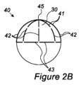
より具体的には、図2Aは、その中心45から放射状に広がる、遠位縦方向電極区画41と、半径方向に区画41の線を継続する、近位縦方向電極区画42と、球形拡張可能要素30の赤道の周囲に円周方向線を作成する、円周方向電極区画43とを有する、電極構造40によって被覆される、その拡張状態時の球形拡張可能要素30の上面図である。狭い間隙が、各電極区画および隣接する区画の端部の間で見られる。本電極構造は、例えば、膀胱の中でアブレーションパターン10を作成するように構成されてもよい。
More specifically, FIG. 2A shows a spherically
図2Bおよび2Cは、それぞれ、ここでは球形拡張可能要素30の上端において見られる、その中心45からその円周に向かって放射状に広がる、遠位縦方向電極区画41と、区画41の線を継続する、近位縦方向電極区画42と、球形拡張可能要素30の赤道の周囲に円周方向線を作成する、円周方向電極区画43とを有する、電極構造40によって被覆される、その拡張状態時の球形拡張可能要素30の側面図および斜視3次元図である。細い間隙が、各電極区画および隣接する区画の端部の間で見られる。本電極構造は、膀胱の中でアブレーションパターン10を作成するように構成されてもよい。
2B and 2C respectively continue the line of
多くの実施形態では、拡張可能要素30は、本明細書では「バルーン」と称される、弾性柔軟バルーンまたは非柔軟バルーンのいずれかであってもよい。ケージまたは類似構造を含む、他の球形拡張可能要素も本開示の範囲内である。
In many embodiments,
注目すべきこととして、例えば、シリコーン、ラテックス、または低デュロメータポリウレタンから作製される柔軟バルーンは、伸張され得、その壁厚を低減させるため、より小さい直径により容易に折り畳まれる、または圧縮されるという利点を有し得る。 Of note, flexible balloons made from silicone, latex, or low durometer polyurethane, for example, can be stretched to reduce their wall thickness and thus are more easily folded or compressed due to their smaller diameter. may have advantages.
対照的に、小直径シースの中へ嵌合することはより困難であるが、例えば、PET、PEBAX、架橋ポリウレタン、ナイロン、Mylar、ポリエステル、ポリウレタン、および架橋または非架橋形態の他のポリマー等から作製される非柔軟または半柔軟バルーンは、電極と器官壁との間により良好な壁並置を生成し得るため、有利であり得る。高い圧力まで膨張されたとき、非柔軟バルーンは、剛性になり、したがって、電極の間のバルーンの膨隆またはバルーンの中への電極の「沈没」を防止し得る。代わりに、剛性状態まで膨張される非柔軟バルーンは、強制的に電極を標的組織の中へわずかに膨出させ得る。 In contrast, it is more difficult to fit into small diameter sheaths such as PET, PEBAX, cross-linked polyurethane, nylon, Mylar, polyester, polyurethane, and other polymers in cross-linked or non-cross-linked form. Non-flexible or semi-flexible balloons made may be advantageous because they may create better wall apposition between the electrodes and organ walls. When inflated to high pressure, a non-flexible balloon becomes rigid and thus may prevent balloon inflation between the electrodes or "sinking" of the electrodes into the balloon. Alternatively, a non-flexible balloon inflated to a rigid state may force the electrode to bulge slightly into the target tissue.
構造40では、全ての電極区画41、42、および43は、球体の円周の約1/8であり得る、実質的に同一の長さを有してもよい。約170ccまで膨張されるヒト膀胱では、これは、典型的には、約27mmの長さに対応するであろう。いくつかの実施形態では、円周方向電極区画は、縦方向電極区画よりも長く、バルーンが上記の体積を上回って膨張することを可能にし得る。より高い体積まで膨張されたとき、円周方向電極は、バルーンを上に移動させ、(赤道の上方の)より高い緯度においてバルーンを包囲してもよい。
In
図3は、電極構造40の概略2次元表現である。図3が3次元構造の2次元投影であるため、図式表現では、異なる電極区画が異なる長さを有するように見えるが、本実施形態では、全ての区画が、拡張可能要素30の円周の8分1に等しくあり得、したがって、全て同一の長さを有し得ることに留意されたい。
FIG. 3 is a schematic two-dimensional representation of
図3には、尖部45により近い遠位縦方向電極区画41a-h、赤道線により近い近位縦方向電極区画42a-h、および赤道線を形成する円周方向電極区画43a-hが示されている。
FIG. 3 shows distal
図3-5では、電極区画は、中心45の周囲のそれらの場所を表す、それらの参照番号上の付加的文字「a」から「h」で標識される。例えば、電極区画41aおよび42aは、12時にある、43aは、12時と1時30分との間の円弧に跨架する、41bおよび42bは、1時30分にある、43bは、1時30分と3時との円弧に跨架する、等である。本標識は、具体的区画を参照するときに、以下で使用されるであろう。
In FIGS. 3-5, the electrode sections are labeled with additional letters "a" through "h" on their reference numbers to represent their location around
電極エネルギー結合および電極アクティブ化シーケンスの種々の組み合わせが、本構造とともに使用されることができる。 Various combinations of electrode energy coupling and electrode activation sequences can be used with the present structure.
遠距離双極アブレーションを採用する、2つのそのような電極アクティブ化シーケンスが、図4-5に示される。これらの図では、電極セットが、細い鎖線で包囲されたアブレーションの各段階においてアクティブ化され、電極のグループが、太い連続線でマークされた一方の極として作用し、他方のグループが、太い鎖線でマークされた他方の極として作用する、図3のような電極構造40の同一の概略2次元表現が使用される。
Two such electrode activation sequences employing long-range bipolar ablation are shown in FIGS. 4-5. In these figures, a set of electrodes is activated at each stage of ablation surrounded by a thin dashed line, with a group of electrodes acting as one pole marked by a thick continuous line and another group marked by a thick dashed line. The same schematic two-dimensional representation of the
図4a-4dはそれぞれ、アブレーション手技シーケンス実施形態中の電極アクティブ化の単一の段階を表し得る。電極アクティブ化の各そのような段階中に、電力は、(細い鎖線によって包囲されて示される)電極区画のアクティブなセットに送達されてもよい。段階の間の遷移は、典型的には、順次的であり得、すなわち、各段階内のアブレーションの完了後に、次の段階がアクティブになるため、合計4つの段階がある。代替として、電力は、全てのアブレーションがほぼ同時に完了するまで、全ての段階の間で連続的に繰り返されてもよい。 4a-4d may each represent a single stage of electrode activation during an ablation procedure sequence embodiment. During each such stage of electrode activation, power may be delivered to the active set of electrode compartments (shown enclosed by a thin dashed line). Transitions between stages can typically be sequential, ie, after completion of ablation within each stage, the next stage becomes active, so there are four stages in total. Alternatively, power may be repeated continuously between all stages until all ablations are completed approximately simultaneously.
より具体的には、図4Aが、一方の極として並列にアクティブ化される、中心45の周囲に十字パターンを作成する、4つの等しく分配された遠位縦方向電極区画41a、41c、41e、および41gを示す一方で、遠位電極区画の間で等距離に分配される、4つの近位縦方向電極区画42b、42d、42f、および42hは、他方の極として並列にアクティブ化されてもよい。これは、縦方向線パターンの半分を生成してもよい。
More specifically, FIG. 4A shows four equally distributed distal
図4Bが、一方の極として並列にアクティブ化される、中心45の周囲に十字パターンを作成する、他の4つの等しく分配された遠位縦方向電極区画41b、41d、41f、および41hを示す一方で、遠位電極区画の間で等距離に分配される、4つの近位縦方向電極区画42a、42c、42e、および42gは、他方の極として並列にアクティブ化されてもよい。これは、縦方向線パターンの欠落している半分を完成させてもよい。
FIG. 4B shows four other equally distributed distal
図4Cは、一方の極として並列にアクティブ化される2つの対向する円周方向電極区画43bおよび43fを示しているが、第1対の電極区画の間で等距離に分配される2つの対向する円周方向電極区画43dおよび43hは、他方の極として並列にアクティブ化されてもよい。これは、円周方向線パターンの半分を生成する。
FIG. 4C shows two opposing
図4Dが、一方の極として並列にアクティブ化される、他の2つの対向する円周方向電極区画43aおよび43eを示す一方で、第1対の電極区画の間で等距離に分配される、2つの対向する円周方向電極区画43cおよび43gは、他方の極として並列にアクティブ化されてもよい。これは、円周方向線パターンの欠落している半分を完成させてもよい。
While FIG. 4D shows two other opposing
図5a-5dはそれぞれ、別のアブレーション手技シーケンス実施形態中の電極アクティブ化の単一の段階を表し得る。電極アクティブ化の各そのような段階中に、電力は、(細い鎖線によって包囲されて示される)電極区画のアクティブなセットに送達されてもよい。段階の間の遷移は、典型的には、順次的であり得、すなわち、各段階内のアブレーションの完了後に、次の段階がアクティブになるため、合計4つの段階がある。代替として、電力は、全てのアブレーションがほぼ同時に完了するまで、全ての段階の間で連続的に繰り返されてもよい。 5a-5d may each represent a single stage of electrode activation during another ablation procedure sequence embodiment. During each such stage of electrode activation, power may be delivered to the active set of electrode compartments (shown enclosed by a thin dashed line). Transitions between stages can typically be sequential, ie, after completion of ablation within each stage, the next stage becomes active, so there are four stages in total. Alternatively, power may be repeated continuously between all stages until all ablations are completed approximately simultaneously.
図5Aが、一方の極として並列にアクティブ化される、中心45の周囲に扁平Xパターンを作成する、4つ遠位縦方向電極区画41a、41b、41e、および41fを示す一方で、遠位電極区画の間で等距離に分配される、4つの近位縦方向電極区画42c、42d、42g、および42hは、他方の極として並列にアクティブ化されてもよい。これは、縦方向線パターンの半分を生成してもよい。
While FIG. 5A shows four distal
図5Bが、一方の極として並列にアクティブ化される、中心45の周囲に扁平Xパターンを作成する、他の4つ遠位縦方向電極区画41c、41d、41g、および41hを示す一方で、遠位電極区画の間で等距離に分配される、4つの近位縦方向電極区画42a、42b、42e、および42fは、他方の極として並列にアクティブ化されてもよい。これは、縦方向線パターンの欠落している半分を完成させてもよい。
While FIG. 5B shows four other distal
図5Cが、一方の極として並列にアクティブ化される、2つの隣接円周方向電極区画43aおよび43bを示す一方で、2つの対向する隣接円周方向電極区画43eおよび43eは、他方の極として並列にアクティブ化されてもよい。これは、円周方向線パターンの半分を生成する。
While FIG. 5C shows two adjacent
図5Dが、一方の極として並列にアクティブ化される、別の2つの隣接円周方向電極区画43cおよび43dを示す一方で、2つの対向する隣接円周方向電極区画43gおよび43hは、他方の極として並列にアクティブ化されてもよい。これは、円周方向線パターンの欠落している半分を完成させてもよい。
While FIG. 5D shows another two adjacent
本明細書に説明される実施形態では、4つの別個の段階で給電される24個の電極区画を使用して、パターン10が作成されるが、遠距離双極は、任意の数の電極区画および給電段階を使用して、基本的に任意のパターンを作成するために使用され得ることに留意することが重要である。実施例として、本アブレーションパターン10を作成するために、より多数の段階(例えば、4の代わりに8)で給電される、より多数の区画(例えば、24の代わりに48)を使用することが可能である。これは、各個々の区画によって作成される損傷の制御および一貫性を増加させるという利点を提供し得るが、これは、デバイス、発電機、製造、および全体的費用の増加した複雑性の対価で生じ得る。
In the embodiments described herein,
上記で説明される遠距離双極技術は、種々の方法およびデバイスを使用して実装されてもよい。いくつかのそのような実施形態が、図6-8に説明される。 The long-range bipolar techniques described above may be implemented using a variety of methods and devices. Some such embodiments are illustrated in FIGS. 6-8.
フレックス回路設計 flex circuit design
図6は、フレキシブルPCB材料を利用し、縦方向電極構造を形成して、全ての電極の配線を促進し得る、デバイス50の実施形態の簡略化された縦断面図である。
FIG. 6 is a simplified longitudinal cross-sectional view of an embodiment of a
遠位から近位まで、図6は、非外傷性キャップ52と、フレックス回路プレート54と、フレックス回路アーム56と、先端プラグ58と、遠位バルーン縮径部62および近位バルーン縮径部64を有する、バルーン60と、内側シャフト66と、遠位リング68と、ストッパ70と、近位リング72と、外側シャフト74と、フレックス回路アーム近位リング76と、外側シース78と、シースポート82および弁シール84を備える、摺動弁80と、摺動ストッパ86と、筐体92、スロット94、外側シャフト基部96、外側シャフトシール98を備える、ハンドル90と、後退ノブ100と、内側シャフト基部102と、ワイヤ104と、電気プラグ106と、膨張管108と、コックの栓110と、レバー122、歯124、解放ボタン126、およびヒンジ128を備える、係止機構120とを備える、デバイス50を示す。
From distal to proximal, FIG. 6 shows
より具体的には、内側シャフト66は、基部102を介してハンドル90に、先端プラグ58を介してフレックス回路プレート54に固定されてもよい。ワイヤ104は、内側シャフト66の長さを通して延設し、基部102を通してそれに進入し、先端プラグ58を通して退出してもよく、そこで、ワイヤ104は、フレックス回路プレート54に接続する。ワイヤ104は、それらの近位端において電気プラグ106に接続されてもよい。
More specifically,
膨張管108は、基部102を介して内側シャフト66の管腔に接続してもよい。基部102は、当技術分野で公知であるような接着剤または封止剤を使用して、ワイヤ104および膨張管108の進入点の周囲に密閉されてもよい。内側管66の遠位端は、フレックス回路プレート54と接続するワイヤ104の通過を可能にしながら、先端プラグ58および当技術分野で公知であるような接着剤または封止剤によって、密閉されてもよい。本実施形態では、ワイヤ104は、内側シャフト66管腔の中および外へのそれらの通過点において固定されてもよく、これらの点の周囲の密閉を達成しやすくする。
内側シャフト66はさらに、バルーン60の膨張を可能にする、近位開口部130と、遠位開口部132とを備えてもよい。ストッパ70は、開口部130および132の近位に位置してもよく、内側シャフト66にわたる外側シャフト74の移動を限定してもよい。
外側シャフト74は、外側シャフト基部96に固定されてもよい。後退ノブ100は、スロット94を介して筐体92から外へ突出してもよい。外側シャフト74は、内側シャフト66の周囲に摺動可能に位置付けられてもよく、ハンドル90の遠位端を介して筐体92から外へ摺動可能に通過してもよい。外側シャフトシール98は、それらの間の漏出を防止しながら、内側シャフト66の周囲の外側シャフト基部96の摺動を可能にし得る。
いくつかの実施形態では、バルーン60が完全に膨張されたときに、外側シャフトシール98を通したある程度の漏出が、わずか、例えば、最大約2cc/分のままである限り、内側シャフト66にわたる外側シャフト74の円滑な移動を可能にするよう、本漏出が許容され得る。
In some embodiments, as long as some leakage through the
近位リング72は、外側シャフト74の遠位端に固定されてもよい。近位バルーン縮径部64は、近位リング72に固定して接続されてもよく、遠位バルーン縮径部62は、内側シャフト66の遠位リング68に固定して接続されてもよい。両方のバルーン縮径部が、これらの取付部の周囲に密閉されてもよい。
したがって、後退ノブ100を引動することは、外側シャフト74を内側シャフト66に関して近位に移動させてもよく、バルーン60の縦方向伸張を結果として生じ、それを直線化し、その外径を縮小し、小さい外径において挿入を可能にし得る。基部96が係止機構120の歯124を通過するとき、歯124は、基部96の遠位移動を防止し、したがって、本位置で外側シャフト74を係止してもよい。
Accordingly, pulling the
解放ボタン126を押すことは、ヒンジ128の周囲でレバー122を回転させ、係止機構120の歯124を解放し、外側シャフト74の遠位移動を可能にしてもよい。これは、典型的には、バルーン膨張に先立って行われてもよい。
Pressing the
係止機構120の解放後、外側シャフト74は、再度、内側シャフト66にわたって自由に摺動してもよい。バルーン60は、次いで、コックの栓110、膨張管108、内側シャフト66、および開口部130および132の管腔を介して、膨張されてもよい。バルーン60の膨張は、それが膨張するにつれて外側シャフト74を遠位に拡張、短縮、および引動させてもよい。
After release of
フレックス回路アーム56の遠位端は、それらがフレックス回路プレート54と連続的であり得、それがひいては、内側シャフト66の遠位端に接続および密閉され得る、先端プラグ58に接続され得るため、内側シャフト66の遠位端に固定して取り付けられてもよい。
The distal ends of the
対照的に、フレックス回路アーム56の近位端は、外側シャフト74の周囲に摺動可能に位置付けられ得る、フレックス回路アーム近位リング76においてともに接続されてもよい。本実施形態では、デバイス50は、典型的には、約170ccのバルーン膨張体積とともに使用されるように構成されてもよいが、フレックス回路プレート54から近位リング76までの縦方向フレックス回路アーム56の長さは、随意に、任意の妥当な体積まで膨張されるバルーンの周囲でそれらが半径方向に拡張することを可能にするために十分に長く作製されてもよい。例えば、バルーン60が約400cc(本用途に関して非常に大きい体積と見なされ得る)まで膨張された場合、フレックス回路プレート54から近位リング76までの縦方向フレックス回路アーム56の長さが、少なくとも約14.4cmであってもよい一方で、170ccバルーン体積に関して、約10.8cmの長さが十分であろう。
In contrast, the proximal ends of
上記で説明される構造は、フレックス回路アーム56が外側シャフト74にわたって自由に摺動することを可能にし得る。後退ノブ100を近位に引動し、バルーン60を伸張することは、外側シャフト74の近位リング72にフレックス回路アーム近位リング76を同一方向に引動させ、したがって、また、フレックス回路アーム56によって形成される縦方向電極構造を伸張および平坦化してもよい。
The structure described above may allow
バルーン60の膨張中に、フレックス回路アーム近位リング76は、それがバルーン60の拡張によって遠位に引動されるにつれて、外側シャフト74に沿って自由に摺動してもよく、フレックス回路アーム56がバルーン60と別個に半径方向に拡張することを可能にする。これは、バルーン60が、柔軟材料から作製される一方で、フレックス回路アームが、非柔軟材料から作製され、それらの円周に沿った種々の点において、それらのそれぞれの異なる程度の伸張を生成し得る場合において、特に重要である。
During inflation of
バルーン60が非柔軟または半柔軟材料から作製される場合において、バルーン60の折り畳みが、フレックス回路アーム56に接続された場合に達成されることができない構成を成すことをそれに要求し得るため、バルーンおよびフレックス回路アーム56の別個の拡張が、依然として有利であり得る。代替として、または組み合わせて、具体的場所におけるバルーン60とフレックス回路アーム56との間の焦点接続が、望ましくあり得る。
In cases where the
上記で説明されるように、内側シャフト66は、ハンドル90に固定して接続されてもよく、外側シャフト74は、内側シャフト66にわたって摺動可能であり得るが、ハンドル90のスロット94内で摺動し得る、後退ノブ100に固定して接続されてもよく、したがって、外側シャフト74の回転を防止する。したがって、内側シャフト66および外側シャフト74は両方とも、相互およびハンドル90に関して一定の配向を維持する。これは、本デバイスの後退に干渉し得る、電極構造の意図的ではない捻転を防止するため、重要であり得る。加えて、本配列は、ユーザが電極の配向を制御することを可能にし、これは、以下でさらに説明されるであろうように、アブレーションパターンの非対称性がある設計において重要である。
As explained above, the
いくつかの実施形態では、フレックス回路アーム近位リング76の回転はさらに、例えば、当技術分野で公知であるように、非円形断面等の方向特徴を含む、外側シャフト74およびフレックス回路アーム近位リング76を作製することによって、防止されてもよい。これは、電極の捻転を防止する、さらなる手段である。
In some embodiments, rotation of the flex circuit arm
代替として、類似結果が、内側管66に沿った縦方向スロット、および該スロットの内側で摺動し得る、外側管74からの突出を提供することによって、達成されてもよい。そのような配列は、例えば、外側シャフトシール98を外側シャフト74の遠位端まで移動させることによって、漏出を防止するために、外側シャフト74と該スロットの遠位にある内側シャフト66との間にシールを作成することを要求し得る。
Alternatively, a similar result may be achieved by providing a longitudinal slot along the
シース78は、それらの間にシールを作成する弁80を伴って、外側シャフト74にわたって摺動可能に位置付けられてもよい。弁80は、当技術分野で公知であるように、要素の間で良好なシールおよび摺動の両方を可能にすることができる、任意の好適な弁、例えば、Tuohy-Borst弁であってもよい。シース78は、デバイス50の折り畳みまたは圧縮位置で、フレックス回路縦方向アーム56、バルーン60、および内側シャフト66を被覆するように、遠位に移動されることができる。完全折り畳みまたは圧縮状態で、シース78の遠位端は、非外傷性キャップ52の近位端と同一平面であり得る。
非外傷性キャップ52は、典型的には、平滑な縁を伴う、丸みを帯びた構造を備えてもよい。これは、ドーム形であり得るが、典型的には、電極から離れた組織の押動を防止するように、約3~5mmまたはそれを下回る厚さを有し、むしろ平坦であり得る。その縁は、随意に、外側シース78の遠位先端の一部または全体を被覆するように側方に延在してもよい。これは、プラスチック、ゴム、金属、または任意の他の生体適合性材料から作製されてもよく、アブレーションデバイス50の遠位端に接着、溶接、ねじ留め、または別様に取り付けられてもよい。いくつかの実施形態では、非外傷性キャップ52は、単に、アブレーションデバイス50の遠位端に、典型的には、フレックス回路プレート54に適用される、接着剤また他のタイプのコーティングの層を備えてもよい。さらに他の実施形態では、非外傷性キャップ52は、フレックス回路プレート54のみから成ってもよい。さらに他の実施形態では、非外傷性先端52は、随意に、身体の中への挿入後または流体との接触後に溶解し得る、ゲルから作製されてもよい。
摺動ストッパ86は、身体の中への挿入の深度を事前測定された尿道深度または所望の展開深度に限定するように、シース78に沿って容易に摺動され、ユーザによる所望に応じて任意の場所で係止されることができる、要素を備えてもよい。
Sliding
図7aは、デバイス50の実施形態の電極構造40を説明する。
FIG. 7a illustrates the
より具体的には、図7aは、図3に示されるものに一般的に類似する、電極構造40の概略上面図である。電極構造40は、フレックス回路プレート54を含む、フレキシブルPCB140と、近位端142を有する、フレックス回路アーム56と、遠位コネクタ144と、近位コネクタ146と、遠位縦方向電極区画41と、近位縦方向電極区画42と、絶縁トラック147とを備えてもよい。電極構造40はさらに、典型的には、ワイヤ、編組、または他の好ましくは可撓性の伝導性材料から作製される、円周方向電極区画43を備えてもよい。
More specifically, FIG. 7a is a schematic top view of an
明確にするために、絶縁トラックおよび円周方向電極のうちのいくつかのみが示されている。しかしながら、典型的には、全てのフレックス回路アームは、PCBの異なる層の中に延設し得る、絶縁トラック147によって必要に応じて作製される接続とともに、それらの上の電極区画41および42と、それらの間の円周方向電極区画43とを有し得ることを理解されたい。
For clarity, only some of the insulating tracks and circumferential electrodes are shown. However, typically all flex circuit arms are connected to electrode
また、円周方向電極区画43の長さは、それが3次元構造の2次元表現であることに起因して、図7aに現れるよりも典型的に短くあり得ることにも留意されたい。
It should also be noted that the length of
PCBに戻ると、フレックス回路プレート54は、本実施形態の電極構造40、および内側シャフト66を通して延設し得、典型的には、ワイヤ104を遠位コネクタ144にはんだ付けすることによって、それに接続され得る、ワイヤ104のための基部としての役割を果たしてもよい。
Returning to the PCB,
フレックス回路縦方向アーム56は、フレックス回路プレート54から半径方向に延在してもよい。典型的には、8つのアーム56があってもよいが、この数は、1から約20まで変動し得る。
A flex circuit
図7aに示されるように、各タイプのいくつかの電極区画は、絶縁トラック147を介して、相互に、および少なくとも1つの遠位コネクタ144に接続されてもよい。典型的には、1つの極として作動する、4つの遠位縦方向電極区画41の各セットは、1つの遠位コネクタ144に接続されてもよく、1つの極として作動する、4つの近位縦方向電極区画42の各セットは、別の遠位コネクタ144に接続されてもよく、1つの極として作動する、2つの円周方向電極区画43の各セットは、さらに別の遠位コネクタ144に接続されてもよい。
As shown in FIG. 7a, several electrode sections of each type may be connected to each other and to at least one
例えば、図5A-5Bに示されるような縦方向電極を駆動するために、隣接するフレックス回路アーム56上の2つの遠位縦方向電極区画41および対向するアーム上の2つが、1つのワイヤ104によって送給され、一方の極を形成し得る、同一の遠位コネクタ144(「a」と標識される)に接続されてもよい一方で、隣接するフレックス回路アーム56上の2つの近位縦方向電極区画42および対向するアーム上の2つは、別のワイヤ104によって送給され、他方の極を形成し得る、別の遠位コネクタ144(「b」と標識される)に接続されてもよい。
For example, to drive longitudinal electrodes as shown in FIGS. 5A-5B, two distal
同一の実施例を継続すると、図5C-5Dに示されるような円周方向電極区画を駆動するために、隣接するフレックス回路アーム56上の2つの円周方向電極区画43が、1つのワイヤ104によって送給され、一方の極を形成し得る、同一の遠位コネクタ144(「c」と標識される)に接続されてもよい一方で、隣接するフレックス回路アーム56上の2つの対向する円周方向電極区画43は、別のワイヤ104によって送給され、他方の極を形成し得る、別の遠位コネクタ144(図示せず)に接続されてもよい。
Continuing with the same example, two
デバイス50の上記の実施形態を製作するときに、内側シャフト66遠位端から外へ通過するワイヤ104は、その後、随意に、先端プラグ58を使用して、内側シャフト66の遠位先端に接続され得る、フレックス回路プレート54の遠位コネクタ144にはんだ付けされてもよい。フレックス回路アーム56は、内側シャフト66の縦軸と平行に屈曲されてもよく、フレックス回路近位端142は全て、外側シャフト74の周囲のフレックス回路アーム近位リング76において相互に接続されてもよい。
When fabricating the above embodiment of
円周方向電極区画43は、近位コネクタ146にはんだ付けされ、隣接するフレックス回路アーム56の間に「ブリッジ」を作成してもよい。
図8Aおよび8Bは、それぞれ、その折り畳みまたは圧縮状態、および、完全展開および膨張状態時のデバイス50を説明する。
8A and 8B illustrate
より具体的には、図8Aは、その折り畳みまたは圧縮状態50時のデバイス50の簡略化された概略縦断面図である。
More specifically, FIG. 8A is a simplified schematic longitudinal cross-sectional view of the
遠位から近位まで、非外傷性先端52、収縮したバルーン60を覆う、それらの圧潰状態時のフレックス回路脚部56および円周方向電極区画43、摺動弁80およびシースポート82および摺動ストッパ86を伴う外側シース78、外側シャフト74、内側シャフト66、筐体92を備えるハンドル90、係止機構120、解放ボタン126、後退ノブ100、および膨張管108が見られる。
From distal to proximal,
円周方向電極区画43は、それらの中央において屈曲されて見られ、各区画の両方の半分は、内側シャフト66の縦軸と平行になり、構造がシース78の内側に嵌合することを可能にする。
The
係止機構120は、近位位置で外側シャフト74を保持し、バルーン60を縦方向に伸張して示されている。電極構造を伴うバルーン60は、圧潰され、外側シース78によって被覆されて示されている。
図8Bは、その展開膨張状態50’時のデバイス50の簡略化された概略縦断面図である。
FIG. 8B is a simplified schematic longitudinal cross-sectional view of the
遠位から近位まで、非外傷性先端52、膨張したバルーン60を覆う、それらの拡張状態時のフレックス回路脚部56および円周方向電極区画43、摺動弁80およびシースポート82および摺動ストッパ86を伴う外側シース78、外側シャフト74、内側シャフト66、筐体92を備えるハンドル90、係止機構120、解放ボタン126、後退ノブ100、および膨張管108が見られる。
From distal to proximal, the
係止機構120は、その解放状態で示され、外側シャフト74は、バルーン60によって遠位に引動されて、遠位位置で示されている。外側シース74は、完全に膨張されたバルーン60および拡張された電極構造を伴って、近位に引き寄せられて示されている。円周方向電極区画43は、殆ど完全に直線化されて見られ、膀胱の赤道の周囲のアブレーション線の作成を可能にする。
上記の実施形態における縦方向電極区画41および42は、典型的には、約0.5mm×25mmであり、銅または他の導電性材料から作製される、典型的には、PCB材料の露出トラックから作製されてもよい。寸法は、典型的には、0.2mm×10mm~1mm×50mmの間で変動し得る。
The
上記の実施形態における円周方向電極区画43は、近位コネクタ146にはんだ付けされ得る、30AWG(米国ワイヤゲージ規格)、すなわち、直径約0.25mmの裸線、銅、または別の導電性材料から作製されてもよい。ステンレス鋼、銀等、または例えば、金または他のめっきを伴う銅等の異なる材料から作製されるワイヤまたは編組ケーブルが、これらの区画に使用されてもよい。異なるゲージのワイヤもまた、使用されることができ、典型的には、これは、28~32ゲージの範囲内であろう。
The
TBPを実施するためのデバイス50の使用は、図8A-8Bを参照して以下で説明される。
The use of
適切な洗浄およびドレーピング後に、尿道長または所望の展開深度が、最初に、フォーリーカテーテルを使用して測定されてもよく、局所麻酔が、膀胱に注入されてもよい。摺動ストッパ86は、非外傷性先端52から対応する距離を置いて、外側シース78にわたって係止されてもよい。弁80は、本デバイスの意図的ではない展開を防止するように係止されてもよい。
After appropriate irrigation and draping, the urethral length or desired deployment depth may be first measured using a Foley catheter and local anesthesia may be injected into the bladder. A sliding
図8Aで見られるような、折り畳まれた、または圧縮されたデバイス50は、摺動ストッパ86が外尿道口に到達するまで、尿道の中に挿入されてもよい。弁80は、次いで、解放されてもよい。
A folded or
患者の身体に対して移動しないように定位置でシース78を保ちながら、ハンドル90は、前方に押動されてもよく、したがって、本デバイスを展開し、すなわち、それを外側シース78から外へ通過させる。
While keeping the
解放ボタン126は、係止機構120を解放するように押されてもよい。バルーン60は、膨張管108を介して流体で膨張されてもよく、図8Bに示されるように、外側シャフト74をハンドル90から外へ遠位に摺動させ、縦方向フレックス回路アーム56および円周方向電極区画43をバルーン60の周囲で半径方向に拡張させる。
膀胱は、シースポート82を通して電極およびバルーン60の周囲で排出されてもよい。
The bladder may be evacuated around the electrode and
電極セットの間のインピーダンスの測定が、実施されてもよく、その後に、膀胱壁上の所望のアイソレーションラインパターンのアブレーションのために、上記で説明されるような遠距離双極技術を利用して、RF発生器を用いた電極の通電が続く。 Measurements of impedance between the electrode sets may be performed, followed by ablation of the desired isolation line pattern on the bladder wall, utilizing a long-range bipolar technique as described above. , followed by energization of the electrodes using an RF generator.
流体は、膀胱体積がバルーン収縮中に実質的に安定して保たれ得るように、随意に、バルーンから膀胱に流体を移送することによって、シースポート82を介してバルーンおよび電極の周囲で膀胱に注入されてもよい。本方法は、バルーンおよび電極構造の圧潰および本デバイスの除去への干渉を防止し得る。
Fluid is optionally transferred to the bladder around the balloon and electrodes through the
後退ノブ100は、外側シャフト74を後退させ、バルーン60を伸張し、縦方向フレックス回路アーム56および円周方向電極区画43を圧潰するように、近位に引動されてもよい。いったん十分に近位に引動されると、係止機構120は、係止してもよく、ハンドル90は、電極構造を伴うバルーン60をシース78の中へ後退させるように、定位置でシース78を保持しながら引動されてもよい。
ハンドル90は、次いで、患者の身体からデバイス50を除去するように、さらに近位に引動されてもよい。
上記の実施形態の種々の修正が、有利であり得る。 Various modifications of the embodiments described above may be advantageous.
いくつかの実施形態では、外側シース78の遠位先端は、それを非外傷性にするように修正されてもよい。
In some embodiments, the distal tip of
例えば、外側シース78の遠位先端は、患者の身体へのその挿入中に組織へのいかなるダメージも防止するために非常に丸みを帯びて平滑であるように、熱または当技術分野で公知であるような他の方法を使用して、充填または別様に処理されてもよい。
For example, the distal tip of the
外側シース78の遠位先端は、加えて、または代替として、類似プロセスを使用して、軟質に作製されてもよい。より剛性からより軟質への堅さへの遷移は、ある距離にわたって、典型的には、2~20mmに沿って、徐々に起こり得る。
The distal tip of
外側シース遠位先端79の別の好ましい実施形態が、それ以外は図8a-8bと同じである、図8c-8dに示される。
Another preferred embodiment of the outer sheath
外側シース遠位先端79は、加えて、図8cに示される折り畳みまたは圧縮状態で、非外傷性キャップ52またはフレックス回路プレート54まで遠位に延在し、それらを被覆し得るように、外側シース78のより近位の部分よりも狭く作製されてもよい。外側シース遠位先端79は、狭いが、図8dに示されるような展開中に遠位に、および後退中に近位に、非外傷性キャップ52、フレックス回路プレート54、電極構造40、および拡張可能要素30の通過を可能にするために、十分に可撓性であり得る。
The outer sheath
図7aでは、各円周方向電極区画43は、1つの「給電された」フレックス回路アーム56(すなわち、電力を送達してもよい)上の近位コネクタ146に接続され、そこから電力を受電し、「デッド(dead)」(すなわち、電力を送達しない場合がある)隣接するフレックス回路アーム56上の別の近位コネクタ146に接続する。
In FIG. 7a, each
いくつかの実施形態では、円周方向電極区画43への電力は、各2つの「デッド」フレックス回路アーム56の間に「給電された」フレックス回路アーム56が存在し得るように、フレックス回路アーム56のうちの4つのみを通して送達されてもよい。
In some embodiments, power to the
図7bは、そのような実施形態の電極構造40の概略描写である。「給電された」フレックス回路アーム56が、「p」でマークされる(かつクロスハッチで示されている)一方で、「デッド」状態のフレックス回路アーム56は、「d」でマークされる。
Figure 7b is a schematic depiction of an
分かり得るように、各対の円周方向電極区画43は、それらの間の1つの「給電された」フレックス回路アーム56から電力を受電してもよく、各円周方向電極区画43は、別個の隣接する「デッド」フレックス回路アーム「d」に接続してもよい。そのような配列は、PCBを単純化し得る。
As can be seen, each pair of
円周方向電極区画のための銅ワイヤの使用は、高い伝導度、低い費用、および使いやすさという利点を提供し得る。 The use of copper wire for the circumferential electrode sections may offer the advantages of high conductivity, low cost, and ease of use.
しかしながら、これらのワイヤは、可鍛性であり、バルーンが収縮されるときでさえも、その開放位置で本デバイスを維持する傾向があり、電極構造の圧潰を引き起こすために、外側シャフトの引動およびシース78の中への後退を要求する。
However, these wires are malleable and tend to maintain the device in its open position even when the balloon is deflated, and the pulling of the outer shaft and Request retraction into
加えて、これらのワイヤは、同一の点における繰り返しの屈曲の結果としての疲労に起因して、破損する傾向がある。使い捨てデバイスに関して、これは、典型的には十分であるが、しかしながら、より耐久性の設計に関して、以下の修正のうちのいずれかが利用されてもよい。 Additionally, these wires are prone to failure due to fatigue as a result of repeated bending at the same point. For disposable devices, this is typically sufficient, however, for more durable designs, any of the following modifications may be utilized.
可能性として考えられる修正は、編組ケーブルまたはワイヤの使用を含んでもよい。編組は、あまり容易に疲労しない場合があり、その材料に応じて、非可鍛性であり得る。例えば、ステンレス鋼ケーブルが、使用されることができ、その伝導度が低すぎると見なされる場合、銀ワイヤまたは他の高度伝導性材料が、伝導度を増加させるようにそれに組み込まれることができる。 Possible modifications may include the use of braided cables or wires. The braid may not fatigue very easily and, depending on its material, may be non-malleable. For example, a stainless steel cable can be used and if its conductivity is deemed too low, silver wire or other highly conductive materials can be incorporated into it to increase the conductivity.
そのような編組を近位コネクタ146に接続することは、編組ケーブルがはんだ付けされたときにウィックとして作用する傾向があるため、レーザ溶接を要求し、硬化された脆弱な区画をもたらし得る。
Connecting such a braid to the
典型的には、「給電された」近位コネクタ146へのそのようなはんだ付けまたは溶接は、PCB内に埋め込まれた導線が良好なアンカを提供するため、耐久性取付部を結果として生じ得る。しかしながら、「デッド」近位コネクタ146に接続するとき、コネクタがPCBの外層上の表面はんだパッドである場合、取付部は、脱離する傾向があり得る。これは、例えば、たとえ本導線が電源に接続しない(「デッド」状態にある)場合があっても、PCB内に埋め込まれた十分に長い延在部を有し得る、近位コネクタ146を提供することによって、解決され得る。
Typically, such soldering or welding to the "powered"
代替として、図7Cに示されるように、「デッド」近位コネクタ146’は、フレックス回路アームに孔を備えてもよい。円周方向電極区画43は、図7cで描写されるように、本孔を通過させられ、それら自体の周囲でループ状にされて捻転され、次いで、隣接するフレックス回路アーム56上の「給電された」近位コネクタ146にはんだ付けされてもよい。
Alternatively, the "dead" proximal connector 146' may include a hole in the flex circuit arm, as shown in FIG. 7C. The
いくつかの可能性として考えられる修正は、円周方向電極区画43のためのワイヤの代わりに、縦方向電極区画41および42のために上記で説明されるような同一のフレックス回路を利用してもよい。
Some possible modifications are to utilize the same flex circuit as described above for
図9Aは、各円周方向電極区画43が各フレックス回路縦方向アーム56からの単純な分岐であり得る、実施形態を示す。本実施形態では、各円周方向区画43は、1つの側面のみにおいて接続されてもよい。シース78の中へ引動されたとき、区画43は、PCB140の面から外へ移動することによって、折り畳み、アーム56と平行な位置を取る。本折り畳みが有意な体積を占めるため、各フレックス回路縦方向アーム56からの分岐は、各折り畳みがシースの内側の異なる高さで生じ、これらの折り畳みの間に最小限の重複を作成し、したがって、シースの小さい直径の中への圧着を可能にするように、アーム56に沿ってわずかに異なる高さに位置付けられる。
FIG. 9A shows an embodiment in which each
Rとマークされた分岐の半径は、圧着中にシースの中へ引動されたときに、その中への円周方向区画34の進入を促進するように構成されてもよい。 The radius of the branch marked R may be configured to facilitate entry of the circumferential section 34 into the sheath when pulled into the sheath during crimping.
図9Bは、区画43が、フレックス回路ヒンジ150によって1つのフレックス回路アーム56に、かつ隣接するフレックス回路アーム56上のループまたは孔154を通して、そこからハンドル90まで通過する緊締ワイヤ152によって、該隣接するアーム56に回転可能に接続される、フレックス回路の別個のストリップを備えてもよい、円周方向電極区画43の異なる実施形態を示す。バルーン60の膨張後または中に、緊締ワイヤ152は、近位に引動されてもよく、円周方向電極区画43を各2つの隣接するアーム56の間に延在させる。緊締ワイヤ152の解放、緊締ワイヤ152とループ154との間の十分に低い摩擦、およびその展開位置にあるときの区画43の十分な角度は、バルーン収縮後の折り畳み位置に戻る圧着およびシース78の中への引動を可能にし得る。ワイヤの付加的セットは、随意に、緊密に引動されたときに、ワイヤの本第2のセットが区画43の折り畳みを引き起こし、それらをアーム56と平行にさせるように、各区画43の先端に接続され、各近位縦方向電極区画42の遠位端に位置付けられる第2のループを通過させられてもよい。本実施形態では、ヒンジ150は、区画の回転を可能にするため、およびそれらの間の電流の伝導のための両方に役立ち得る。
FIG. 9B shows that
図9Cは、各円周方向電極区画43が、中央ヒンジ156によって相互に、かつフレックス回路ヒンジ150によって2つの隣接するアーム56のそれぞれに回転可能に接続される、フレックス回路の2つの別個のストリップを備えてもよい、類似実施形態である。本構造は、バルーン60が膨張するにつれて直線化してもよく、収縮後およびシース78の中への引動中に(鋏のように)折り返してもよい。
FIG. 9C shows two separate strips of flex circuit in which each
図9Dは、ヒンジが「ジグザグ」パターンでフレックス回路を切断することによって作成され得る、フレックス回路ヒンジ150または中央ヒンジ156の実施形態150aを示す。これは、切断面積における屈曲と、その結果として単一の部品として印刷されることができる、PCBを通したヒンジを横断する導体の通過とを可能にし得、多くの回転ヒンジを組み立てる必要性を排除する。これらの切断は、(上記で説明される図9Cのように)円周方向電極としてのPCB分岐の使用を促進するために使用されてもよい。
FIG. 9D shows an
図10A-10Cは、ループ154を通過させられる、区画43の端部からの緊締ワイヤ152が、バルーン60の膨張後に、その展開位置まで区画43を引動するために、上記の図9Bに関して説明されるように使用されてもよい、図9Aに示されるものに類似する実施形態を示す。本実施形態は、実際の露出電極区画43として使用されるPCB140の裏面であるという点で異なる。利点は、それがヒンジを有していないため、本区画43は、PCB140の裏面を外向きに向けることによって折り畳まれた、または圧縮されたときに、最も容易に折り畳まれ、現在説明されている実施形態では、外側に向くPCBの側面を変更する必要がないため、本区画の展開は、より容易であり得ることである。
10A-10C are described with respect to FIG. 9B above, in which a tacking
上記のデバイス50は、例えば、対向する電極の等しい長さが使用される限り、遠距離双極技術を依然として使用しながら、上記で説明されるようなアブレーションから膀胱の後面を温存する、非対称電極構造(前方へと傾斜している)を用いて作製され得ることに留意されたい。図11は、そのような可能性として考えられる設計を説明する。
The
より具体的には、図11は、上円周方向電極区画160、下円周方向電極区画162、前縦方向電極区画164、後縦方向電極区画166、および対角電極区画168を示す、球形拡張可能要素30にわたる電極構造40の簡略化された概略側面図である。
More specifically, FIG. 11 shows a spherical electrode section showing an upper
上円周方向電極区画160および下円周方向電極区画162は、球形拡張可能要素30の赤道線から同一の距離にあってもよく、したがって、同一の長さであってもよく、それらを双極対として使用するために適切にする。対角電極区画168は、構造40の各側面に1つずつ位置し、また、良好な双極対であってもよい。
The upper
前縦方向電極区画164および後縦方向電極区画166の部品の種々の組み合わせもまた、遠距離双極技法を使用して、本パターンを作成することを可能にするために、双極対として使用されてもよい。
Various combinations of parts of the front
他の実施形態では、遠距離双極は、不平等な長さの対向する電極とともに使用されてもよい。むしろ、各電極における等しい程度のアブレーションは、電極の表面積を等しくする(より短い電極が等しい割合でより幅広い)ことによって、達成されてもよい。 In other embodiments, long-range bipoles may be used with opposing electrodes of unequal length. Rather, an equal degree of ablation at each electrode may be achieved by making the electrodes have equal surface areas (shorter electrodes are equally wider).
他の実施形態では、遠距離技術は、2つの電極の間の意図的な非対称性とともに使用されてもよい。本構成は、1つの電極(または電極のセット)が、異なる表面に、または異なる圧力において適用されるときに、有用であり得る。本構成の一実施例は、膀胱円蓋に並置される、比較的より長い区画を、膀胱の側壁に並置される、比較的より短い区画と結合することであってもよい。本構成は、例えば、(例えば、本デバイスの長軸に沿って印加される指圧または他の原因に起因して)、円蓋における接触圧力が側壁における接触圧力を超えるときに、有用であり得る。したがって、円蓋における増加した接触圧力は、(増加した電極長に起因して)減少した電流密度によって相殺されてもよく、結果として生じるアブレーションは、依然として電極長を通して対称であり得、表面積は、異なる。 In other embodiments, long-range techniques may be used with intentional asymmetry between the two electrodes. This configuration may be useful when one electrode (or set of electrodes) is applied to different surfaces or at different pressures. One example of this configuration may be to combine a relatively longer section that is apposed to the bladder vault with a relatively shorter section that is apposed to the side wall of the bladder. This configuration may be useful, for example, when the contact pressure at the fornix exceeds the contact pressure at the sidewall (e.g., due to finger pressure applied along the long axis of the device or other sources). . Therefore, the increased contact pressure at the fornix may be offset by the reduced current density (due to the increased electrode length) and the resulting ablation may still be symmetrical across the electrode length, with the surface area different.
他の実施形態では、遠距離双極技術は、非対称損傷を誘発する意図を伴って、非対称電極とともに使用されてもよい。本構成は、異なる解剖学的ゾーンが結合された電極を用いてアブレートされるときに有用であり得る。本構成の実施例は、円周方向電極において増加した電流密度および増加した損傷深度を有する意図を伴って、より長い遠位(本デバイスの先端により近い)電極を、より短い円周方向電極と結合することを含む。本構成は、腹腔内にある膀胱の解剖学的領域中により浅い損傷、および腹腔と直接接触していない領域中により深い損傷を作成する際に有用であり得る。別の実施例は、(女性の)膣および男性の精嚢等の敏感な器官に隣接する、膀胱の後側において特異的により浅い損傷を作成するために、より長い後線をより短い前線と結合することであってもよい。 In other embodiments, long-range bipolar techniques may be used with asymmetric electrodes, with the intent of inducing asymmetric lesions. This configuration may be useful when different anatomical zones are ablated using combined electrodes. Examples of this configuration combine longer distal (closer to the tip of the device) electrodes with shorter circumferential electrodes, with the intention of having increased current density and increased lesion depth in the circumferential electrodes. Including combining. This configuration may be useful in creating shallower lesions in anatomical areas of the bladder that are within the peritoneal cavity, and deeper lesions in areas that are not in direct contact with the peritoneal cavity. Another example combines a longer posterior line with a shorter anterior line to create a shallower lesion specifically on the posterior side of the bladder, adjacent to sensitive organs such as the vagina (in females) and the seminal vesicles in males. It may also be a combination.
さらに別の実施例は、以下で詳述されるであろうように、例えば、具体的領域における局所的治療が所望されるときに、目標が、一方の極における有意な損傷の作成、および、他方の極における損傷なしまたはわずかな損傷の作成である、状況を含んでもよい。 Yet another example is, as will be detailed below, for example, when localized treatment in a specific area is desired, the goal is to create a significant lesion at one pole, and It may include situations where there is no damage or the creation of slight damage at the other pole.
さらなる改良および変形例 Further improvements and variations
展開制御 Deployment control
デバイス50の有用な修正は、係止機構120が解放される前に、バルーン60を誤って膨張させる可能性を防止することを伴う。係止機構を解放することに先立った、そのような膨張は、バルーンおよび/または電極にダメージを与え得る。
A useful modification of
係止機構の解放前の膨張を防止することは、係止機構120が係止される限り、内側シャフト66の管腔が閉鎖されたままであるように、例えば、その係止位置にあるときに外側シャフト基部96によって圧縮されると閉鎖する、内側シャフト66の近位端の近傍に安全弁を組み込むことによって、容易に達成されることができる。係止機構120の解放は、外側シャフト基部96が遠位に移動することを可能にし、本安全弁を解放し、膨張が行われることを可能にし得る。
Preventing expansion prior to release of the locking mechanism is such that the lumen of the
別の有用な修正は、フレックス回路縦方向アーム56が後退ノブ100を使用して緊張した状態で引動される前に、シース78の中へバルーンおよび電極を後退させる可能性を防止することを伴う。縦方向フレックス回路アームが緊張した状態で引き寄せられることに先立った、そのような後退は、デバイス除去と干渉し得る、結果として生じる外向きの突出を伴って、シース78によるそれらの圧縮を引き起こし得る。
Another useful modification involves preventing the possibility of retracting the balloon and electrodes into the
縦方向アームが緊張した状態で引き寄せられる前に後退を防止することは、例えば、外側シャフト基部96が係止機構120の係止位置に到達するまで、定位置でシース78を係止するレバーをハンドル90の中に組み込むことによって、容易に達成されることができる。
Preventing retraction before the longitudinal arm is pulled under tension may, for example, be accomplished by locking a lever that locks the
軸力印加 Axial force applied
アブレーション中の本デバイス50の縦軸に沿った軸力の印加は、電極と膀胱壁との間の接触を改良し、より均質なアブレーションパターンを達成することを補助し得る。本力は、典型的には、1~20N、好ましくは、2~10Nであってもよい。
Application of an axial force along the longitudinal axis of the
そのような軸力の印加は、ユーザによって手動で実施されてもよい。 Application of such an axial force may be performed manually by a user.
力に対する制御は、例えば、随意に、過剰な力が印加された場合に作動するであろうアラームを伴って、ばねベースのゲージをハンドルの中に組み込むことによって提供されてもよい。 Control over force may be provided, for example, by incorporating a spring-based gauge into the handle, optionally with an alarm that will trip if excessive force is applied.
本軸力を印加するための別の方法が、図12に示される。図12は、デバイス50の簡略化された概略縦断面図である。本デバイスは、ストッパ70が除去され得、または内側シャフト66上でより遠位に位置付けられ得、スロット94の中のノブ100のより長い可動域を可能にするように、ケーシング92およびスロット94がより長く製作され得ることを除いて、図6で前述に説明されたものと同じである。
Another method for applying main axial force is shown in FIG. 12. FIG. 12 is a simplified schematic longitudinal cross-sectional view of
本デバイスを用いると、図12に示されるように、バルーン60への軸力の印加は、後退ノブ100を遠位に押動することによって実施されてもよく、これは、バルーン60の短縮およびその軸方向直径の増加を引き起こし得、したがって、その方向に印加される半径方向力も増加させ、膀胱壁との円周方向電極の接触を改良し得る。軸力はまた、バルーンの遠位端に位置する縦方向電極の組織接触を改良し得る。
With this device, as shown in FIG. 12, application of an axial force to balloon 60 may be performed by pushing
接触力測定 Contact force measurement
電極と膀胱壁との間の実際の接触力の測定は、有益であり得、例えば、電極のうちの少なくとも1つ以上のものに隣接して、またはその上に、小型センサを配置することによって実施されてもよい。 Measuring the actual contact force between the electrodes and the bladder wall may be useful, for example by placing miniature sensors adjacent to or on at least one or more of the electrodes. may be implemented.
これに使用され得る小型センサは、例えば、Interlink Electronics(Camarillo, CA 93012, USA)製の400シリーズ等の力感知抵抗器を含む。 Small sensors that can be used for this include, for example, force sensing resistors such as the 400 series manufactured by Interlink Electronics (Camarillo, CA 93012, USA).
Harvard Apparatus(Holliston, MA 01746, USA)製のFISO-LSシリーズ光ファイバマイクロカテーテル圧力変換器等の圧力センサもまた、接触力の推定に使用されてもよい。 Pressure sensors, such as the FISO-LS series fiber optic microcatheter pressure transducers manufactured by Harvard Apparatus (Holliston, Mass. 01746, USA), may also be used to estimate contact force.
本開示はさらに、電極・膀胱接触圧力を査定する別の方法を説明する。本方法によると、バルーンの中の容積およびバルーンの中の圧力(好ましくは、バルーン自体において測定される)は、連続的に監視されてもよい。臨床実践において達成される容積/圧力グラフ(「測定圧力」)は、同一のバルーンの台上試験(「期待圧力」)と比較される。バルーンの中の任意の所与の容積に関して、測定バルーン圧力と期待バルーン圧力との間の差は、バルーン・膀胱接触圧力である。 The present disclosure further describes another method of assessing electrode-bladder contact pressure. According to the method, the volume within the balloon and the pressure within the balloon (preferably measured in the balloon itself) may be continuously monitored. The volume/pressure graph achieved in clinical practice ("measured pressure") is compared to a bench test of the same balloon ("expected pressure"). For any given volume within the balloon, the difference between the measured balloon pressure and the expected balloon pressure is the balloon-bladder contact pressure.
バルーンは、所望の接触圧力が達成されるまで、膨張、押動、または変形されてもよい。 The balloon may be inflated, pushed, or deformed until the desired contact pressure is achieved.
適切なバルーン体積の事前選定 Preselection of appropriate balloon volume
前述で説明された、いくつかの実施形態では、縦方向フレックス回路アーム56は、可変長であってもよく、バルーンは、種々の体積まで膨張されることができる。円周方向電極の長さも、(前述で説明されたように)可変であり得る、またはバルーン膨張の範囲全体に適応するために十分に長くなるように固定されてもよい(バルーンが完全に膨張されていないときに若干折り畳まれる)。いくつかの実施形態では、デバイスの挿入に先立って、膀胱体積および圧力が、(尿流動態検査のように)測定されてもよく、所望の接触圧力を達成する膀胱の体積が、留意されることができる。最適な接触圧力は、典型的には、5cmH2O~100cmH2O、好ましくは、10cmH2O~40cmH2Oの範囲内であってもよい。いったん本体積が留意されると、本デバイスは、次いで、所望の接触圧力を達成するように、本体積まで膨張されてもよい。
In some embodiments, as described above, the longitudinal
加えて、バルーンの体積は、測定され、電極要素に対して追加応力を加えることなく、または組織に対して電極を押圧する所望の圧力/力を伴わずに空隙を残すことなく、バルーンが展開幾何学形状内でより良好に嵌合するように、縦方向電極および円周方向電極の本展開幾何学形状によって画定される体積と相関する必要があり得る。 In addition, the volume of the balloon is measured and the balloon is deployed without applying additional stress on the electrode elements or leaving a void without the desired pressure/force to press the electrode against the tissue. It may be necessary to correlate the volume defined by the present unfolded geometry of the longitudinal and circumferential electrodes to better fit within the geometry.
最適な展開位置の事前選定 Pre-selection of optimal deployment position
いくつかの実施形態では、バルーンは、固定膨張体積を有してもよい。これらの実施形態では、膀胱内のバルーンの位置(膀胱頸部から前方の変位)は、電極・膀胱接触圧力に影響を及ぼし得る。いくつかの実施形態では、最適な変位は、流体で充填されたときの膀胱の撮像によって、事前定義され得る。最適な膀胱圧力に達したとき、膀胱の長軸が測定されてもよく、本デバイスは、次いで、強制的に膀胱に同一の測定長を帯びさせるであろう位置で展開されてもよい。例えば、膀胱は、40cmH2Oの圧力に達するまで、流体で充填されてもよい。膀胱の長軸が、次いで、測定されてもよい(本実施例の目的のために、これは、12cmであると仮定されるであろう)。次いで、本デバイスは、(いったん膨張されると)本デバイスの先端が膀胱頸部から12cmであり得るように、導入および展開されてもよい。いくつかの実施形態では、本デバイスシャフト上の明確なマーキングは、ユーザが本デバイスの中の距離を明確に見ることを可能にし得る。 In some embodiments, the balloon may have a fixed inflation volume. In these embodiments, the position of the balloon within the bladder (displacement anteriorly from the bladder neck) can affect the electrode-bladder contact pressure. In some embodiments, the optimal displacement may be predefined by imaging the bladder when filled with fluid. When optimal bladder pressure is reached, the long axis of the bladder may be measured and the device may then be deployed in a position that will force the bladder to take on the same measured length. For example, the bladder may be filled with fluid until a pressure of 40 cm H2O is reached. The long axis of the bladder may then be measured (for purposes of this example this will be assumed to be 12 cm). The device may then be introduced and deployed such that (once inflated) the tip of the device may be 12 cm from the bladder neck. In some embodiments, clear markings on the device shaft may allow the user to clearly see distances within the device.
最適な展開位置を選定することの別の利点は、三角部面積が回避されることを確認することであってもよい。(撮像、尿流動態検査、または膀胱鏡検査によって査定されるような)膀胱サイズが許容する場合、展開位置は、三角部および尿管の排尿筋内区画がアブレーションから温存されることを確認するように選定されることができる。 Another benefit of choosing the optimal deployment location may be to ensure that triangular areas are avoided. If bladder size allows (as assessed by imaging, urodynamic testing, or cystoscopy), the deployment position ensures that the trigone and the intradetrusor compartment of the ureter are preserved from ablation. can be selected as follows.
自動制御 Automatic control
デバイス50のさらなる修正は、その機能および制御の多くの自動制御を伴い得る。本自動制御は、おそらく、好ましくは、コントローラ/発電機ユニットによって実行されてもよい。
Further modifications of
制御された段階および作用は、以下の特徴および本明細書に列挙されていない付加的特徴のうちのいずれかまたは全てを含んでもよい。 Controlled steps and actions may include any or all of the following features and additional features not listed herein.
自動展開(シースから外へシャフトを移動させる)は、患者の尿道の中へのプローブの挿入、およびユーザによってボタンを押動した、またはフットスイッチをアクティブ化した後に、コントローラによって動作され得る、リニアまたは他の電気モータを使用して、実装されることができる。本モータは、例えば、シース78に対して遠位にハンドル90を押動し得る。コントローラは、モータによって印加される力を測定し、過剰な力が患者の組織に及ぼされていないことを確実にし得る。
Auto-deployment (moving the shaft out of the sheath) can be operated by the controller after insertion of the probe into the patient's urethra and by the user pressing a button or activating a footswitch. or can be implemented using other electric motors. The motor may, for example, push handle 90 distally relative to
後退ノブの自動解放 Automatic release of retraction knob
これは、上記で説明されるように機械的に、またはいったん完全展開に達したことをセンサが感知すると電子的に、達成されてもよい。 This may be accomplished mechanically as described above, or electronically once a sensor senses that full deployment has been reached.
バルーンの自動膨張は、電子ポンプをアクティブ化し、または電子弁を開放して、既知の圧力において流体またはガス流を可能にすることによって、コントローラによって実施されてもよい。圧力、流速、および送達される全体積は、監視および制御されてもよい。いくつかの実施形態では、急速バルーン充填が、膀胱を急速に伸張し、したがって、(膀胱が新しい増加した体積に弛緩するために十分な時間を有する前に)接触圧力を増加させるように、適用されてもよい。 Automatic inflation of the balloon may be performed by the controller by activating an electronic pump or opening an electronic valve to allow fluid or gas flow at a known pressure. Pressure, flow rate, and total volume delivered may be monitored and controlled. In some embodiments, rapid balloon filling is applied to rapidly stretch the bladder and thus increase the contact pressure (before the bladder has sufficient time to relax to the new increased volume). may be done.
軸力の自動印加 Automatic application of axial force
軸力は、本力がコントローラによって自動的に印加され得るという差異を伴って、上記で説明されるように、内側シャフト66に印加されてもよい。本目的のために、患者に対するハンドル90の位置は、コントローラによって制御される必要があり得る。
The axial force may be applied to the
代替として、または組み合わせて、軸力は、本力がコントローラによって自動的に印加され得るという差異を伴って、上記で説明されるように、デバイス50の外側シャフト74に印加されてもよい。本目的のために、患者に対するハンドル90の位置は、ユーザにより、コントローラによって制御される必要があり得る、または空間内で固定されてもよい一方で、コントローラは、ハンドル90上で遠位に後退ノブ100を押動し得る、モータを作動させてもよい。力は、モータの動作を調節し、所望の範囲内で力を保つことによって、コントローラによって監視および制御されてもよい。
Alternatively, or in combination, an axial force may be applied to the
接触力の測定に従った自動調節-電極・膀胱壁接触力の測定は、上記で説明されるように実施され、コントローラによって監視されてもよい。これらのデータおよびインピーダンス測定等の付加的データは、軸力、膨張体積または圧力、またはアブレーション電力、時間、またはアブレーション結果に影響を及ぼす他のパラメータを調節するために、別個に、またはともに使用されてもよい。 Automatic adjustment following contact force measurements - Electrode-vesical wall contact force measurements may be performed as described above and monitored by the controller. These data and additional data such as impedance measurements may be used separately or together to adjust axial force, inflation volume or pressure, or ablation power, time, or other parameters that affect ablation results. It's okay.
そのような調節は、随意に、履歴データおよびそれらと関連付けられる適切な治療設定を含有するデータベースとの上記の測定の比較に基づいて、実施されてもよい。 Such adjustments may optionally be performed based on a comparison of the above measurements to a database containing historical data and appropriate treatment settings associated therewith.
バルーンから膀胱への流体の移送による自動バルーン収縮 Automatic balloon deflation by transferring fluid from the balloon to the bladder
コントローラによる、電子ポンプ、随意に、バルーン膨張に使用される同一のポンプの動作は、本流体移送を実施するように自動的に開始されることができる。代替として、または組み合わせて、膀胱につながる管およびバルーンにつながる管は、同一のポートに接続されてもよく、明確にマークされた弁は、現在開放している経路(バルーンまたは膀胱)を表示し、それを選定することを可能にしてもよい。 Operation of an electronic pump, optionally the same pump used for balloon inflation, by the controller can be automatically initiated to perform the present fluid transfer. Alternatively, or in combination, the tube leading to the bladder and the tube leading to the balloon may be connected to the same port, with clearly marked valves indicating which pathway is currently open (balloon or bladder). , it may be possible to select it.
バルーンおよび電極の自動圧潰 Automatic collapse of balloons and electrodes
後退ノブを近位に引動することは、コントローラアクティブ化電気モータによって実施されてもよい。 Proximally pulling the retraction knob may be performed by a controller activated electric motor.
シャフトの自動後退 Automatic retraction of shaft
シース78に対して近位にハンドル90を引動することは、コントローラアクティブ化電気モータ、随意に、かつ好ましくは、自動展開に使用される同一のモータによって実施されてもよい。
Drawing
ピーク温度を超えた場合のアブレーションの自動停止 Automatic termination of ablation if peak temperature is exceeded
いくつかの実施形態では、本デバイスは、アブレーション熱に対する制御を可能にする温度センサを有していない場合があり、アブレーション温度を限定することは、バルーン自体によって達成されてもよい。いくつかの実施形態では、バルーン材料および壁幅は、ある温度閾値を超える熱と接触しているときにバルーンが裂けるように選択される。バルーンの破裂は、接触圧力を低減させることによって、かつバルーンからの流体で洗い流すことによって、その時点でアブレーションを即時および自動的に低減させ得る。加えて、または代替として、圧力センサは、バルーン圧力の低減(またはバルーン体積の損失)を感知し、アブレーションを自動的に中断してもよい。いくつかの実施形態では、バルーン材料は、ポリウレタンであり、標的体積における壁厚は、0.02~0.005mmであり、摂氏約70度を上回って加熱されたときに、意図的にバルーンが破裂する可能性を高くし、したがって、手技を中断する。 In some embodiments, the device may not have a temperature sensor to allow control over the ablation heat, and limiting the ablation temperature may be accomplished by the balloon itself. In some embodiments, the balloon material and wall width are selected such that the balloon ruptures when in contact with heat above a certain temperature threshold. Rupture of the balloon may immediately and automatically reduce ablation at that point by reducing contact pressure and flushing with fluid from the balloon. Additionally or alternatively, the pressure sensor may sense a decrease in balloon pressure (or loss of balloon volume) and automatically interrupt the ablation. In some embodiments, the balloon material is polyurethane, the wall thickness in the target volume is between 0.02 and 0.005 mm, and the balloon is intentionally heated to above about 70 degrees Celsius. increasing the chance of rupture and therefore aborting the procedure.
電極・組織接触を改良するための手段 Means to improve electrode-tissue contact
電極と組織との間の良好な機械的および電気的接触を確実にすることは、満足できるアブレーション結果を達成するために重要であり得る。本接触を改良することを意図している、本デバイスの種々の随意の側面が説明される。 Ensuring good mechanical and electrical contact between the electrode and tissue can be important to achieving satisfactory ablation results. Various optional aspects of the device are described that are intended to improve the contact.
流体除去 fluid removal
拡張可能要素30の展開および拡張後に、電極と器官壁との間の過剰な流体は、電極・組織接触を改良するように除去されてもよい。これは、電極と器官壁との間の空間に吸引を印加することによって行われてもよい。そのような吸引は、図13a-dに示される、以下の手段のうちのいずれか(または組み合わせ)を使用して、印加されてもよい。図13aが、アブレーションデバイス50の概略縦断面図である一方で、図13b-dは、図13aではQでマークされた線のレベルにおけるデバイス50の軸方向断面図である。以下の段落で追加される情報は別として、図13aは、図8bと同じである。
After deployment and expansion of
a. いくつかの実施形態では、例えば、シースポート82を介した、外側シース78への吸引の印加は、少なくとも器官の近位面積から流体を容易に除去してもよい。外側シース78の遠位端の周囲のシース吸引孔200の追加は、外側シース78を介して吸引を印加する能力をさらに改良し、その開口部を詰まらせる組織の可能性を低減させ得る。
a. In some embodiments, application of suction to
b. いくつかの実施形態では、吸引は、例えば、内側シャフト66に沿って延在する別個の遠位吸引管腔202を通して、デバイス50の遠位端に印加されてもよい。ワイヤ104は、随意に、該別個の遠位吸引管腔を通過してもよい。遠位吸引管腔ポート201は、デバイス50の近位端において提供されてもよく、少なくとも1つの遠位吸引開口部203は、デバイス50の遠位端において提供されてもよい。
b. In some embodiments, suction may be applied to the distal end of
c. いくつかの実施形態では、吸引は、例えば、フレックス回路アーム56を通して、拡張可能要素30の周囲に印加されてもよい。これは、例えば、その外面の少なくとも一部にわたって流体チャネル204を有する、フレキシブルPCB140によって達成されてもよい。例えば、PCB140は、例えば、フレックス回路プレート54からフレックス回路アーム近位端142まで、または本長さの一部のみに沿って延在し得る、フレックス回路アーム56のうちの少なくともいくつかに沿って小型管204を備えてもよい。小型管204は、例えば、フレックス回路プレート54において管に接続され得る、遠位吸引管腔202等の吸引源に接続されてもよい。小型管204は、バルーン60の周囲の種々の面積からの吸引を可能にする、それらの長さに沿った開口部を有してもよい。
c. In some embodiments, suction may be applied around the
図13bは、それらのそれぞれの上に小型管204を伴う、8つのフレックス回路アーム56によって囲繞される、膨張したバルーン60の中心における遠位吸引管腔202および内側シャフト66を示す、デバイス50の軸方向断面図である。
FIG. 13b shows the
代替として、開放チャネル、吸収生体適合性布のストリップ、または吸引を伝達することが可能な任意の他の材料、特徴、または要素が、小型管204の代わりに使用されてもよい。
Alternatively, an open channel, a strip of absorbent biocompatible fabric, or any other material, feature, or element capable of transmitting suction may be used in place of the
d. いくつかの実施形態では、拡張可能部材30は、それ自体が、吸引を伝達するための少なくとも1つのバルーンチャネル206を備えてもよい。そのようなチャネルは、例えば、バルーンの一部であり、バルーンと同一の材料から作製され得る、バルーン内の管様構造であってもよい。チャネルは、外部吸引源をバルーン表面と接続してもよい、または代替として、チャネルは、1つの面積において印加される吸引が別の面積に伝達されるように、吸引または流体がそれらの間を通過することを可能にするようにバルーンの周囲の異なる空間の間で接続してもよい。例えば、図13aおよび13bに示される、そのようなバルーンチャネル206は、治療された器官壁とバルーンの遠位側との間の空間を、バルーンの近位の空間と接続してもよい。別の実施形態では、バルーンチャネル206は、デバイス50の軸方向断面図である図13cに示されるように、バルーンの外面に沿った少なくとも1つの折り目であってもよい。さらに別の実施形態では、バルーンチャネル206は、デバイス50の軸方向断面図である図13dに示されるように、拡張可能要素30を備える、1つ以上のバルーン60の2つの部品の間に空間を備える。
d. In some embodiments, the
e. 膀胱内で真空(低い圧力)を生成する。いくつかの実施形態では、電極・組織接触は、膀胱から液体およびガスを吸引することによって、膀胱の内側の圧力を低減させることによって改良され得る。そうするために、外側への流体およびガス漏出が制限され得るように、外側シース78およびそれを通して本デバイスが挿入され得る尿道または他の組織の周囲の十分なシールと、外側シース78と内部デバイス構成要素との間(例えば、弁シール84が、外側シース78と外側シャフト74との間を密閉してもよい)および内側デバイス構成要素自体の間のシール(例えば、外側シャフトシール98が、内側シャフト66と外側シャフト74との間を密閉してもよい)とを確実にする、手段が提供されてもよい。
e. Creates a vacuum (low pressure) within the bladder. In some embodiments, electrode-tissue contact may be improved by reducing pressure inside the bladder by drawing fluid and gas from the bladder. To do so, the
いったん十分なシールが確実にされると、膀胱の内側の流体およびガスの吸引は、膀胱内の圧力を、膀胱の中の通常の止血圧力未満および膨張されたときのバルーンの中の圧力未満にさせ得、電極要素に対する接触を改良し得る。 Once a sufficient seal is ensured, suction of fluid and gas inside the bladder reduces the pressure within the bladder below the normal hemostatic force within the bladder and below the pressure inside the balloon when inflated. and improve contact to the electrode elements.
腹腔内圧の意図的な増加 Deliberate increase in intra-abdominal pressure
いくつかの実施形態では、電極・組織接触は、腹腔内圧を増加させることによって改良され得る。これは、手技に先立った、またはその間の、または両方の一過性の増加であってもよい、または少なくとも手技の持続時間にわたって印加され得る、より長く持続する増加であってもよい。 In some embodiments, electrode-tissue contact may be improved by increasing intra-abdominal pressure. This may be a transient increase prior to, during, or both the procedure, or it may be a longer lasting increase that may be applied for at least the duration of the procedure.
腹腔内圧のそのような増加は、多くの方法で誘発されてもよい。 Such an increase in intra-abdominal pressure may be induced in a number of ways.
例えば、意識のある患者では、これは、患者に咳をさせる、またはバルサルバ法を実施させることによって、達成されてもよい。 For example, in a conscious patient, this may be accomplished by having the patient cough or perform a Valsalva maneuver.
全身麻酔下の人工呼吸器をつけた患者では、これは、例えば、換気量または呼気終末気道陽圧を増加させること等の換気パラメータを修正することによって、達成されてもよい。 In mechanically ventilated patients under general anesthesia, this may be accomplished by modifying ventilation parameters, such as increasing tidal volume or positive end-expiratory airway pressure.
ユーザ、典型的には、治療担当医師は、患者の腹部に指圧を印加することによって、患者の腹腔内圧を増加させてもよい。 A user, typically a treating physician, may increase the patient's intra-abdominal pressure by applying finger pressure to the patient's abdomen.
いくつかの実施形態では、上記の組み合わせが、使用されてもよい。 In some embodiments, combinations of the above may be used.
いくつかの実施形態では、腹腔内圧が、例えば、直腸圧プローブを使用して監視されてもよく、フィードバックインジケーションが、圧力の量を制御するように、医師および/または患者に提供されてもよい。 In some embodiments, intra-abdominal pressure may be monitored using, for example, a rectal pressure probe, and feedback indications may be provided to the physician and/or patient to control the amount of pressure. good.
いくつかの実施形態では、測定された腹腔内圧は、圧力が具体的範囲内である間のみ、アブレーションが実施され得、本範囲よりも高いまたは低い場合には自動的に中断され得ることを確実にするために、使用されてもよい。 In some embodiments, the measured intra-abdominal pressure ensures that ablation can only be performed while the pressure is within a specific range and can be automatically interrupted if it is above or below this range. may be used to make
微細共形化電極 Fine conformal electrode
いくつかの状況では、電極と器官壁との間の全体的に良好な接触にもかかわらず、上記で説明される手段後でさえも、電極に沿った少なくともいくつかの点において、電極と組織との間に残る小さい間隙が依然として存在し得る。図14Aに示されるように、これは、例えば、壁の不完全な伸張または他の理由に起因し得る、器官壁2の中の小さい襞210によって引き起こされ得る。さらに、いくつかの器官は、通常、小さい間隙、例えば、膀胱内の皺、または腸内の陰窩およびヴィラ(villa)を引き起こし得る、構造を備え得る。器官壁に沿った堅さ,構造、または寸法の変化が、間隙の別の理由であってもよい。間隙は、小型(すなわち、数ミリメートルの規模)であり得るか、または、微視的(すなわち、数ミクロンの規模)の寸法を有し得る。図14Aは、器官壁2および電極区画42との間の間隙210を示す、フレックス回路アームおよび電極区画42を通した概略縦断面図である。
In some situations, despite generally good contact between the electrode and the organ wall, even after the measures described above, at least some points along the electrode, the electrode and the tissue There may still be a small gap remaining between. As shown in FIG. 14A, this may be caused by
そのような間隙にもかかわらず、電極に沿った連続損傷の作成を確実にするために、これらの状況で接触を改良し得る、電極への種々の修正が、使用されてもよい。 To ensure the creation of a continuous lesion along the electrode despite such gaps, various modifications to the electrode may be used that may improve contact in these situations.
例えば、図14bに示されるように、それらの表面上に伝導性の可撓性またはゼラチン様材料層212を有する電極が、提供されてもよい。図14cに示されるように、材料212は、寸法が数ミクロンであるかまたはミリメートルであるかにかかわらず、組織が突出し、間隙210に押し入る場合に圧縮されるように、器官壁表面に共形化し、したがって、電極区画42と組織2との間の電気的接触を改良し得る。
For example, as shown in Figure 14b, electrodes may be provided with a conductive flexible or gelatin-
可能性として考えられる材料212の実施例は、Sasaki et al. (Highly conductive stretchable and biocompatible electrode-hydrogel hybrids for advanced tissue engineering. Adv Healthc Mater. 2014 Nov;3(11):1919-27)によって説明される、ポリ(3,4-エチレンジオキシチオフェン)/ポリウレタン-ヒドロゲルハイブリッドであってもよい。
Examples of
そのような材料は、随意に、PCB製造中に、または手技の直前のプローブの準備中に手動で、電極に適用されてもよい。 Such materials may optionally be applied to the electrodes manually during PCB manufacturing or during probe preparation immediately prior to the procedure.
組織表面に微細共形化することによって、上記のヒドロゲルと同一の機能を提供し得る、他の材料または構造が、使用されてもよい。 Other materials or structures that can provide the same functionality as the hydrogels described above by microconforming to tissue surfaces may be used.
例えば、電極を構成する、または電極表面から突出する、マイクロファイバから作製される伝導性織物もまた、本機能を提供してもよい。そのようなマイクロファイバは、軟質であり、上記で説明されるヒドロゲルに類似する様式で組織表面に共形化してもよい。代替として、マイクロファイバは、典型的には、1mm以下に限定される浅い深度まで組織を貫通するように、十分な鋭度および軸方向剛性を保有してもよい。 For example, a conductive fabric made from microfibers that constitutes the electrode or protrudes from the electrode surface may also provide this functionality. Such microfibers are soft and may conform to tissue surfaces in a manner similar to the hydrogels described above. Alternatively, the microfibers may possess sufficient sharpness and axial stiffness to penetrate tissue to shallow depths, typically limited to 1 mm or less.
半伝導性媒体 semiconducting medium
電極と組織との間の小さい間隙という問題を解決することを意図している、さらに別の実施形態は、電極と器官壁との間で使用される媒体に関する。典型的には、そのような媒体は、流体であってもよい。以前の開示は、食塩水等の伝導性またはグリシン等の非伝導性のいずれかである、媒体の使用について議論している。 Yet another embodiment intended to solve the problem of small gaps between electrodes and tissue concerns the medium used between the electrodes and the organ wall. Typically such a medium may be a fluid. Previous disclosures discuss the use of media that are either conductive, such as saline, or non-conductive, such as glycine.
生理食塩水または高張食塩水等の高度伝導性媒体は、電極と組織との間の電気的結合を改良するという利点を有し得るが、しかしながら、流体の十分に厚い層が電極と器官壁との間に残される場合に、双極電極の間に「短絡」を生成するという危険を冒し得る。加えて、これは、電極の間のインピーダンス測定の顕著な変化を引き起こさないであろうため、そのような過剰な流体層の存在を識別するユーザの能力を低減させる。 Highly conductive media such as saline or hypertonic saline may have the advantage of improving the electrical coupling between the electrode and the tissue; however, a sufficiently thick layer of fluid may If left between the bipolar electrodes, one could run the risk of creating a "short circuit" between the bipolar electrodes. Additionally, this will not cause a significant change in the impedance measurement between the electrodes, thus reducing the user's ability to identify the presence of such an excessive fluid layer.
グリシンまたはソルビトール等の非伝導性媒体は、機械的電極・組織接触が準最適である場合に、ユーザが、例えば、上記の方法のうちのいずれかによって、状況を識別および修復し得るように、双極電極対の間の測定されたインピーダンスの有意な増加を生成し得るという利点を有し得る。 A non-conductive medium such as glycine or sorbitol is used when mechanical electrode-tissue contact is suboptimal so that the user can identify and repair the situation, e.g., by any of the methods described above. It may have the advantage of producing a significant increase in the measured impedance between the bipolar electrode pair.
本発明は、治療された組織のものと完全な絶縁体との間の伝導度を有し得る、媒体の随意の使用を含む。例えば、膀胱内の治療に関して、そのような媒体は、約0.1ジーメンス/mの具体的伝導度を有し得る、0.1%食塩水であってもよい。本伝導度は、0.2~1.9S/mの伝導度を有するものとして種々のソースで説明される、尿路上皮のものよりも低いが、完全な絶縁体を構成しない。したがって、本流体の薄い層が電極と膀胱壁との間に残留する場合、組織を通した電流の「短絡」または「バイパス」が起こらず、流体の除去の必要性を示す、インピーダンス測定の増加が検出され得る。一方で、電極に沿った組織の襞または皺内の小規模または微視的間隙を充填する流体は、絶縁体として作用しない場合があり、実際に、電流の流れを可能にし、結果としてより連続的な損傷を生じ得る。 The invention includes the optional use of a medium that can have a conductivity between that of the treated tissue and a perfect insulator. For example, for intravesical treatment, such a vehicle may be 0.1% saline, which may have a specific conductivity of about 0.1 Siemens/m. This conductivity is lower than that of the urothelium, which is described in various sources as having a conductivity of 0.2-1.9 S/m, but does not constitute a perfect insulator. Therefore, if a thin layer of this fluid remains between the electrode and the bladder wall, no "shorting" or "bypassing" of the current through the tissue will occur and an increase in impedance measurements will occur, indicating the need for fluid removal. can be detected. On the other hand, fluid filling small-scale or microscopic gaps within tissue folds or wrinkles along the electrode may not act as an insulator and may actually allow current to flow, resulting in a more continuous may cause permanent damage.
いくつかの実施形態では、バルーン膨張圧力を測定する圧力センサは、バルーンからの漏出を含む、種々の状態を検出するために、手技中に使用されてもよい。典型的には、内側シャフト66または膨張管108の近位で測定された場合、圧力は、流体経路の抵抗に起因して、膨張中に急勾配で上昇し得る。圧力は、次いで、数秒以内に減少し、バルーン内の流体体積、バルーンサイズおよび弾性、および膀胱(または他の治療された器官)サイズおよび伸展性を反映する、圧力において安定し得る。
In some embodiments, a pressure sensor that measures balloon inflation pressure may be used during a procedure to detect various conditions, including leakage from the balloon. Typically, pressure when measured proximal to
図15は、そのような手段を使用して生成される、可能性として考えられる膨張曲線を示す、概略グラフである。水平軸は、秒単位で時間を表し、左の垂直軸は、mmHg単位で膨張圧力を表し、右の垂直軸は、ミリメートル単位でバルーンの中へ膨張される体積を表す。描写される実施例では、流体は、それぞれ約60mlの3つのボーラスで膨張される。測定圧力は、アクティブな膨張中に約400mmHgまで増加し、バルーン圧力と平衡化するにつれて、はるかに少なく降下する。第1の流体ボーラス後に、平衡圧力は、ゼロに近く、第2のボーラス後に5~20mmHgまで、第3のボーラス後に約90~150mmHgまで増加する。著者らの経験によると、膀胱が、通常、弛緩する傾向があり、全体的な測定された平衡圧力にわずかに追加するため、本圧力の殆どは、バルーン圧力を反映する。 FIG. 15 is a schematic graph showing possible expansion curves generated using such an approach. The horizontal axis represents time in seconds, the left vertical axis represents inflation pressure in mmHg, and the right vertical axis represents volume inflated into the balloon in millimeters. In the depicted example, the fluid is expanded in three boluses of approximately 60 ml each. The measured pressure increases to approximately 400 mmHg during active inflation and drops much less as it equilibrates with balloon pressure. After the first fluid bolus, the equilibrium pressure is close to zero and increases to 5-20 mmHg after the second bolus and about 90-150 mmHg after the third bolus. According to the authors' experience, most of this pressure reflects balloon pressure because the bladder normally tends to relax and adds slightly to the overall measured equilibrium pressure.
約400mmHgを有意に上回るまでのボーラス膨張中の圧力の増加は、典型的には、バルーンが完全に展開されていない間の膨張、停滞電極構造、または小さいまたは非柔軟性の膀胱、または流体経路の詰まり等の問題を示し得る。ユーザは、上記に起因して、手技を中断または変更することを選定してもよい。 The increase in pressure during bolus inflation to significantly more than about 400 mmHg is typically due to inflation while the balloon is not fully deployed, stagnant electrode construction, or a small or inflexible bladder, or fluid path. This may indicate a problem such as a blockage. The user may elect to abort or modify the procedure due to the above.
前述のように、具体的体積における身体の外側の膨張したデバイスのための圧力が、事前測定されてもよい(「期待圧力」)。 As mentioned above, the pressure for an inflated device outside the body at a specific volume may be pre-measured ("expected pressure").
手技中の平衡膨張圧力が「期待圧力」よりも有意に高い(典型的には、>約20mmHg高い)場合において、ユーザは、膀胱が過剰に小さい、収縮している、または非常に低い伸展性を有すると結論付け得、手技を中断することを選定してもよい。 In cases where the equilibrium inflation pressure during a procedure is significantly higher than the "expected pressure" (typically > about 20 mmHg higher), the user may have a bladder that is excessively small, contracted, or has very low distensibility. may conclude that the patient has a condition and may choose to abort the procedure.
測定された膨張圧力が平衡化しない、または事前測定された「期待圧力」よりもはるかに低いレベルに平衡化する場合において、バルーン漏出が疑われ得、ユーザは、本デバイスを置換することを選定してもよい。 In cases where the measured inflation pressure does not equilibrate or equilibrates to a level much lower than the pre-measured "expected pressure", a balloon leak may be suspected and the user may elect to replace the device. You may.
これは多くの可能性として考えられる膨張プロファイルのうちの1つにすぎないことに留意することが重要である。例えば、平坦な圧力対体積から進み、次いで、体積とともに圧力が単調に増加するものも、可能である。 It is important to note that this is only one of many possible expansion profiles. For example, it is also possible to proceed from a flat pressure versus volume and then a monotonically increasing pressure with volume.
いくつかの実施形態は、拡張可能要素にわたって印刷され得る、電極を伴ってもよい。 Some embodiments may involve electrodes that may be printed across the expandable element.
そのような実施形態の主要な利点は、製造の単純性であり得る。不利点は、以下を含み得る。
第1に、柔軟バルーン上に印刷された場合、そのような印刷電極は、膨張中にそれらの電気的性質を変化させ、したがって、アブレーション結果を予測しにくくし得る。
第2に、そのような電極は、それらが伝導することが可能である電力を限定され得る。
第3に、印刷電極を伴うバルーンは、小さい直径の中へ圧着することがより困難であり得る。
第4に、電極印刷技術は、全てのエラストマに、特に、本用途においてより望ましくあり得る、より熱に耐性があるものに適合しない。
A major advantage of such embodiments may be simplicity of manufacture. Disadvantages may include:
First, when printed on flexible balloons, such printed electrodes can change their electrical properties during inflation, thus making ablation results less predictable.
Second, such electrodes may be limited in the power they are capable of conducting.
Third, balloons with printed electrodes may be more difficult to crimp into small diameters.
Fourth, electrode printing techniques are not compatible with all elastomers, especially those that are more heat resistant, which may be more desirable in this application.
非柔軟バルーンおよびその製造方法 Non-flexible balloon and its manufacturing method
本発明のデバイスのために適切な非柔軟バルーンは、随意に、ブロー成形、RF溶接、または当技術分野で公知である任意の他の方法を使用して、製造されてもよい。実施形態のうちのいくつかのバルーンは、その近位および遠位縮径部直径よりもはるかに大きい膨張直径を有し得るため、標準ブロー成形技法は、初期管が非常に厚く、非常に厚いバルーン縮径部を残すことが必要になり得るか、または、膨張状態で妥当な厚さのバルーン壁を達成するための十分な材料を含有しないことがあり得るかのいずれかであるため、それを製造するためにあまり適切ではない場合があり得る。 Inflexible balloons suitable for the devices of the invention may optionally be manufactured using blow molding, RF welding, or any other method known in the art. Because the balloon in some of the embodiments may have an inflated diameter much larger than its proximal and distal constriction diameters, standard blow molding techniques require that the initial tube be very thick; Either it may be necessary to leave a balloon constriction or it may not contain enough material to achieve a reasonable balloon wall thickness in the inflated state. may not be very suitable for manufacturing.
そのような場合において、少なくとも2つの部分(典型的には、バルーンの2つの半分)から作製されるバルーンのRF溶接(またはレーザ、または超音波溶接、またはバルーン部分を接続する他の形態)が、好適な解決策であってもよい。そのような製造方法の一般的結果は、2つのバルーン部分228を備える、図13aでは線Qによってマークされるものに類似する場所において、溶接バルーン220の概略軸方向断面図である図16aに示されるように、溶接/接続線に沿った外向きのシーム222を伴う溶接バルーン220の生産であってもよい。また、断面上にないが、バルーン縮径部226も図16aに示されている。そのような外向きのシーム222は、少なくとも以下の理由により、すなわち、(1)シームが、折り畳みバルーン外形を拡大し得る、(2)シームが、治療された器官の内面を傷付け得る、および(3)シームが、電極の展開に干渉し得るため、望ましくない場合がある。したがって、外向きに突出するシーム222を伴わない溶接/接続されたバルーンの製造が、望ましくあり得る。そのようなバルーン220’を製造するための方法および装置は、以下および図16b-iに説明される。
In such cases, RF welding (or laser, or ultrasonic welding, or other forms of connecting the balloon parts) of a balloon made from at least two parts (typically the two halves of the balloon) , may be a suitable solution. The general result of such a manufacturing method is shown in FIG. 16a, which is a schematic axial cross-sectional view of a
内向きのシームを伴う溶接バルーン Welded balloon with inward facing seams
いくつかの実施形態では、内向きのシーム224を有し得る、溶接バルーン220’が製造されてもよい。図16bは、内向きのシーム224、バルーン縮径部226、およびバルーン部分228’も示す、図13aでは線Qによってマークされるものに類似する場所における溶接バルーン220’の概略軸方向断面図である。
In some embodiments, a welded balloon 220' may be manufactured that may have an inwardly facing
代替として、バルーンは、外向きのシームが反転され、シームを内向きにさせた状態で、製造されてもよい。 Alternatively, the balloon may be manufactured with the outward facing seams inverted, with the seams facing inwards.
図16cは、その内縁に沿って内向きの「フランジ」230’を備えてもよい、バルーン部分228’の3次元スケッチである。
FIG. 16c is a three-dimensional sketch of a
バルーン部分228’は、ポリマーシートの圧縮成形、射出成形、浸漬、ブロー成形、または当技術分野で公知である任意の他の方法によって、製造されてもよい。
バルーン部分は、それらの「フランジ」が相互に隣接するように、引き合わせられてもよい。これは、随意に、部分を接近させることに役立つように、鋳型またはジグの内側で行われてもよい。 The balloon portions may be drawn together such that their "flanges" abut each other. This may optionally be done inside the mold or jig to help approximate the parts.
バルーン縮径部を通過させられ得、隣接する「フランジ」をともに締め付け得る、特殊「鉗子」232または「ローラ」234が、提供されてもよい。以下の説明では、鉗子232およびローラ234は、同義的に使用される。
Special "forceps" 232 or "rollers" 234 may be provided that can be passed through the balloon constrictor and clamp adjacent "flanges" together. In the following description, forceps 232 and
鉗子232が、図16dに示される一方で、ローラ234は、図16eに示される。鉗子232は、典型的には、その遠位端に一対の並置要素233を伴って、1つの側面に湾曲した、1つ以上の細長い部材231を備えてもよい。
Forceps 232 are shown in Figure 16d, while
ローラ234は、並置要素233上の小さい車輪235の追加を伴って、鉗子232と基本的に同一の構造を有する。
これらは、2つのバルーンフランジをともに締め付け、それらを溶接するためのエネルギーを送達することが可能である、薄型外形の任意の構造が使用され得るため、可能性として考えられる道具の実施例にすぎない。RFエネルギーまたは他の適切な形態のエネルギーが、「鉗子」232の2つの並置要素233の間に、または溶接バルーン220および「鉗子」232の外部に位置付けられるエネルギー源の間に送達されてもよい。そのようなエネルギーは、RFエネルギー、光(例えば、レーザ)、超音波、熱、または当技術分野で公知であるような任意の他のエネルギーであってもよい。
These are only examples of possible tools, as any structure with a low profile that is capable of clamping two balloon flanges together and delivering energy to weld them can be used. do not have. RF energy or other suitable forms of energy may be delivered between the two
図16fは、バルーン220’の製造プロセスの3次元スケッチである。2つのバルーン部分228’は、それらのフランジ230’が相互に隣接する状態で、ともに保持されて示されている。ローラ234は、並置要素233および車輪235がフランジ230’をともに締め付け、それらを内向きのシーム224の中へ溶接する状態で、バルーン縮径部226を横断して見られる。
Figure 16f is a three-dimensional sketch of the manufacturing process for balloon 220'. Two
図16fで描写される実施形態では、ローラ234は、各瞬間にシームの単一の点を溶接し、シームに沿って移動してシームの全長を溶接するために使用されてもよい。矢印は、バルーン縮径部226に向かったローラ234の移動を表す。
In the embodiment depicted in FIG. 16f,
いくつかの実施形態では、一対の「鉗子」232(またはローラ234)が、使用されてもよい。いくつかの実施形態では、少なくとも2対の「鉗子」が、並行して使用されてもよい(例えば、2つの半分から作製されるバルーンに関して、一対は、バルーンの対称性が留保されるように、好ましくは、シームに沿って平行に移動して、バルーンの両側のシーム毎に使用されてもよい)。付加的な対の、例えば、4対の「鉗子」が使用されてもよく、2つが、挿入され、バルーンのいずれかの縮径部から除去される。 In some embodiments, a pair of "forceps" 232 (or rollers 234) may be used. In some embodiments, at least two pairs of "forceps" may be used in parallel (e.g., for a balloon made from two halves, one pair may be used such that the symmetry of the balloon is preserved). , preferably on each seam on each side of the balloon, moving parallel to the seam). Additional pairs, for example four pairs of "forceps" may be used, two inserted and removed from either reduced diameter section of the balloon.
注目すべきこととして、図16fに示されるバルーン220’は、外側に向く1つのバルーン縮径部226と、内向きに反転された1つの縮径部226’とを有する(典型的には、少なくとも遠位バルーン縮径部は、内向きに反転されるであろう)。それにもかかわらず、本デバイスのバルーンは、外側に向く、または内向きに反転された両方の縮径部を有してもよく、依然として、上記の方法のうちのいずれかによって製造されてもよい。代替として、バルーンは、外向きに突出する縮径部を伴って製造されてもよく、縮径部は、製造後プロセスにおいて内向きに反転されてもよい。
Of note, the balloon 220' shown in Figure 16f has one
いくつかの実施形態では、内側に向く代わりに、「フランジ」230’は、バルーン部分壁に対して任意の角度、例えば、接線、外側に向く、または任意の他の角度にあってもよい。そのような実施形態では、「鉗子」232はまた、溶接の直前に、それを隣接するバルーン部分の反対フランジに対面させるように、「フランジ」230を反転させてもよい。 In some embodiments, instead of facing inwardly, the "flange" 230' may be at any angle to the balloon section wall, such as tangential, facing outward, or any other angle. In such embodiments, the "forceps" 232 may also flip the "flange" 230 so that it faces the opposite flange of the adjacent balloon section just prior to welding.
いくつかの実施形態では、バルーン部分の「フランジ」230’は、一度にシーム全体をともに保持するように、随意に、一度にそれを全て溶接するように設計され得る、「クランプ」236によって、バルーンの内側から引き合わせられてもよい。 In some embodiments, the "flange" 230' of the balloon portion is held together by a "clamp" 236, which may optionally be designed to weld it all together at once, to hold the entire seam together. They may be pulled together from the inside of the balloon.
図16gは、例えば、シームのレベルにおけるバルーンの断面の形状でワイヤを備え得る、そのような「クランプ」236の一般的構造の3次元スケッチである。 FIG. 16g is a three-dimensional sketch of the general structure of such a "clamp" 236, which may, for example, comprise a wire in the shape of a cross-section of a balloon at the level of the seam.
図16hは、全てシーム線に沿って、両方の部分228’のフランジを相互に対して押圧し、縮径部226を通してバルーンから退出する際に、シーム224の上方および下方で見られる、クランプ236を使用した製造中のバルーン220’の端面図である。
FIG. 16h shows a
典型的には、少なくとも2つのクランプ236が、各「フランジ」230’の上方に1つ、下に1つ、シーム毎に使用されるであろう。随意に、各クランプ236は、バルーンの中への挿入およびそこからの除去を促進する、少なくとも2つの部分を備えてもよい。
Typically, at least two
突出シームがない溶接バルーン Welded balloon without protruding seams
図16iおよび16jに示される実施例等のいくつかの実施形態では、突出シームがないバルーン240が、製造される。シームは、いずれかの方向に突出しないように、2つのバルーン部分228’の重複238として作成されてもよい。内向きのシームバルーン220’に関して上記で説明されるものに類似する道具および方法は、部分228’の締め付けがバルーンの内側の道具とバルーンの外側の道具との間に存在するであろうという差異を伴って、バルーン240を作製するために使用されてもよい。
In some embodiments, such as the example shown in FIGS. 16i and 16j,
針電極 needle electrode
図17a-eに示されるいくつかの実施形態では、拡張可能要素の周囲に突出し、組織の中に進入する針電極250が、使用されてもよい。
In some embodiments shown in FIGS. 17a-e, a
図17aは、フレックス回路アーム56にわたって電極区画42から突出する、針電極250の概略3次元スケッチである。これは、針250が、41または43等の他の電極区画、または治療された組織と接触し得るアブレーションデバイス50内の任意の他の表面から延在し得るため、一例にすぎない。
FIG. 17a is a schematic three-dimensional sketch of
針250は、フレキシブルPCB140の不可欠な部分として製造されてもよい。代替として、それらは、PCB140に溶接または別様に接続され得る、別個の要素として製造されてもよい。例えば、針250は、ニチノールのストリップをレーザ切断することによって作製されてもよい。
いくつかの実施形態では、針250は、固定されてもよい、すなわち、手技中に変化することなく表面から一定の距離まで突出してもよい。図17bは、そのような固定された針250を伴う区画42の概略縦断面図である。
In some embodiments,
代替として、針250は、手技中に区画42(または任意の他の表面)からのそれらの突出の程度を変化させてもよい。典型的には、そのような実施形態では、針250は、デバイス50の折り畳みまたは圧縮状態では、より少なく突出し、展開状態中に、より多く突出するであろう。
Alternatively, needles 250 may vary their degree of protrusion from compartment 42 (or any other surface) during the procedure. Typically, in such embodiments,
いくつかの実施形態では、針250は、自己展開式であり得る、すなわち、電極区画42から半径方向に突出する固有の傾向を保有してもよい。これは、例えば、区画42に沿った概略縦断面図である図17cに示されるように、外向きの角度で針を固定する針構造の熱処理によって、達成されてもよい。そのような実施形態では、針は、折り畳みまたは圧縮状態で外側シース78の中へ引動されたときに平坦に折り畳まれ、展開状態で跳開するであろう。
In some embodiments,
他の実施形態では、針250は、ニチノール等の形状記憶合金から作製されてもよく、冷たいときに圧潰位置を取り、体温に暴露されたときに半径方向に突出するような方法で熱処理されてもよい。したがって、針250は、デバイス50の折り畳みまたは圧縮状態で容易に折り畳まれ、または圧縮されてもよく、患者の身体の中に挿入されたときのみ突出してもよい。
In other embodiments,
図17d-17eに示される、さらに他の実施形態では、針250は、拡張可能要素30の拡張中のみ突出する。
In yet other embodiments, shown in FIGS. 17d-17e,
デバイス50の折り畳みまたは圧縮状態時の区画42に沿った概略縦断面図である、図17dで見られるように、区画42が平坦である限り(すなわち、折り畳みまたは圧縮状態である間に)、針250’は、平坦であり、区画42と平行である。拡張可能要素30の拡張状態時の拡張可能要素30の区画42に沿った概略縦断面図である、図17eで見られるように、PCB140は、湾曲してもよく、区画42は、円形縦断面を成してもよく、結果として、針250は、区画42の曲面に対して突出してもよい。
As seen in FIG. 17d, which is a schematic longitudinal cross-sectional view along
上記は、実施例であり、当技術分野で公知である他の設計および方法が、針250をデバイス50の折り畳みまたは圧縮状態で圧潰させ、展開または拡張状態中に突出位置を取らせるために使用されてもよい。
The above is an example; other designs and methods known in the art may be used to cause the
針250の突出の程度は、治療される器官および標的組織に応じて、設計によって事前決定および限定されてもよい。例えば、典型的には、膀胱内の治療に関して、針250は、区画42の表面(または任意の他の表面)から0.1mm~1.5mm突出してもよい。本距離は、表面と垂直に測定され、換言すると、図17eのような角度にある場合、針250の長さは、組織の中への突出の上記の深度よりも長くあり得る。
The degree of protrusion of
典型的には、針250は、遠距離双極技術と組み合わせて使用されてもよい。しかしながら、針250はまた、一般的にアブレーションのため、および具体的にはTBPのために、他のアブレーション技術/モダリティとともに使用されてもよい。
Typically,
バルーンの周囲に適用される、種々の上記の吸引方法と組み合わせた針250の使用が、特に有益であり得る。
The use of
針250を使用することの利点は、良好な組織電極・接触を確実にすること、および表面層のアブレーションを回避することが望ましくあり得る場合の両方にあり得る。そのような場合において、針250は、それらの先端を別として、全体にわたって絶縁されてもよい。
Advantages of using
局所的治療 local treatment
器官治療全体または反復パターンを用いて器官の広い面積を標的にする治療(膀胱のTBP等)との関連で、上記で説明されているが、いくつかの実施形態では、遠距離双極技術は、器官の中の局所的で比較的小さい面積の標的治療に使用されてもよい。 Although described above in the context of whole organ treatments or treatments that target large areas of organs using repetitive patterns (such as TBP of the bladder), in some embodiments, distance bipolar techniques It may be used for targeted treatment of localized, relatively small areas within an organ.
いくつかの実施形態では、これは、上記のように、異なる表面積を有する、電極の各セットの2つの極によって達成されてもよい。例えば、標的領域における極が、小さい全表面積を伴う電極を備えてもよい一方で、損傷が所望されない、他方の極における電極は、広い全表面積を有してもよい。そのような場合において、広い表面積の極は、ここでは双極として使用されるにもかかわらず、単極アブレーションの「分散」電極に類似する役割を果たす。 In some embodiments, this may be accomplished with two poles of each set of electrodes, having different surface areas, as described above. For example, the pole at the target area may comprise an electrode with a small total surface area, while the electrode at the other pole, where damage is not desired, may have a large total surface area. In such cases, the high surface area poles, although used here as bipoles, play a role analogous to the "dispersive" electrodes of monopolar ablation.
「治療」電極と「分散」電極との間の表面積の差異は、典型的には、1:2~1:20、好ましくは、1:5~1:10の比であってもよい。 The difference in surface area between the "therapy" electrode and the "dispersion" electrode may typically be in a ratio of 1:2 to 1:20, preferably 1:5 to 1:10.
「遠距離双極」エネルギー結合を使用する、本願の主題である手技に関して、双極対を形成する「治療」および「分散」電極は、ほぼ同一の表面積を有することを意図している。 For the procedures that are the subject of this application using "long-range bipolar" energy coupling, the "therapy" and "distribution" electrodes forming the bipolar pair are intended to have approximately the same surface area.
例えば、膀胱では、三角部が、具体的に標的にされてもよい。これは、例えば、膀胱を除神経する目的で行われてもよい。代替として、これは、三角部の面積内のみで膀胱壁内の信号伝搬を妨害するため、または三角部面積のアイソレーションのために、行われてもよい。 For example, in the bladder, the trigone may be specifically targeted. This may be done, for example, to denervate the bladder. Alternatively, this may be done to disrupt signal propagation within the bladder wall only within the area of the trigone, or for isolation of the trigone area.
実施例として、図18は、遠距離双極を使用して、膀胱三角部を治療するために使用され得る、局所的治療プローブ260の概略3次元スケッチである。プローブ260は、主要な差異が電極区画の位置にある、上記で説明されるプローブ50と基本的に同じであり得る。明確にするために、電極区画のみが示されているが、典型的には、それらは、上記で説明されるPCB140に非常に類似するフレキシブルPCB上に位置付けられてもよい。
As an example, FIG. 18 is a schematic three-dimensional sketch of a
図18で見られるように、2つの短い縦方向電極区画および2つの短い円周方向電極区画(ともに治療アレイ262)は、尿管口5の場所の下方の安全な距離において三角部の面積を標的にして、近位バルーン縮径部に隣接するバルーンの下半球上に位置付けられてもよい。アレイ262の反対側のバルーン60の他方の側面上で、2つの長い縦方向電極区画および6つの長い円周方向区画(ともに分散アレイ264)が、位置付けられてもよい。図18に示される電極区画は、例証の目的のためにすぎず、形状、場所、数等が異なるように設計されてもよい。重要な点は、治療アレイ262が分散アレイ264よりも面積がはるかに小さくあり得ることである。したがって、反対極としての役割を果たし得るアレイ264の中の電極と結合されている間に、1つの極としての役割を果たし得るアレイ262の中の電極にエネルギーを送達するときに、有意な損傷が、治療アレイ262において形成し得る一方で、いかなる損傷も分散アレイ264において形成し得ない、または非常に表面的な損傷が形成し得る。
As seen in FIG. 18, two short longitudinal electrode sections and two short circumferential electrode sections (both treatment array 262) reduce the area of the trigone at a safe distance below the location of the
いくつかの実施形態では、膀胱頸部が、例えば、緊張性尿失禁を治療するための機械的変化を誘発するために標的にされてもよい。 In some embodiments, the bladder neck may be targeted to induce mechanical changes to treat stress urinary incontinence, for example.
膀胱円蓋内の局所的面積は、例えば、そこでの異常活動病巣の識別後に、その面積をアイソレートするために治療されてもよい。代替として、遠距離双極を使用する、膀胱の局所的面積のための治療は、表在性腫瘍、出血、または任意の他の膀胱症状の治療のために行われてもよい。 A localized area within the bladder vault may be treated to isolate that area, for example, after identification of an abnormally active lesion there. Alternatively, treatment for localized areas of the bladder using distance bipolar may be performed for treatment of superficial tumors, bleeding, or any other bladder condition.
いくつかの実施形態では、本発明のデバイスはさらに、治療物質を治療された領域に送達するように適合される。これは、例えば、送達される薬物で治療電極をコーティングすることによって達成されてもよい。組織のアブレーションは、薬物のその透過性および吸収を増加させ得る。電極からの薬物の放出は、電極を通して流れる電流の結果、温度の上昇の結果、または両方であってもよい。 In some embodiments, the devices of the invention are further adapted to deliver therapeutic substances to the treated area. This may be achieved, for example, by coating the therapeutic electrode with the drug to be delivered. Ablation of tissue can increase its permeability and absorption of drugs. Release of drug from the electrode may be a result of current flowing through the electrode, an increase in temperature, or both.
実施例として、膀胱においてこのようにして治療され得る症状は、過活動膀胱、膀胱排尿筋失調、骨盤痛症候群、低活動性膀胱、腫瘍性疾患を含んでもよい。 By way of example, conditions that may be treated in this manner in the bladder may include overactive bladder, bladder detrusor ataxia, pelvic pain syndrome, underactive bladder, and neoplastic disease.
このようにして送達され得る物質は、例えば、数例を挙げると、ボツリヌス毒素、抗コリン作用薬、およびGlivecを含んでもよいが、それらに限定されない。 Substances that can be delivered in this manner may include, for example, but are not limited to, botulinum toxin, anticholinergics, and Glivec, to name a few.
さらに別の実施形態は、バルーンを使用することを伴ってもよく、これは、それに沿ってバルーンが少なくとも部分的に透明であり得る、アブレーションが所望される具体的線を除いて、鏡様または不透明であり得る。 Yet another embodiment may involve using a balloon that is mirror-like or Can be opaque.
図19は、そのような鏡バルーンデバイス270の概略縦断面図である。
FIG. 19 is a schematic longitudinal cross-sectional view of such a
図19には、器官272が示され、その内側で、膨張のための少なくとも1つの管腔を伴うカテーテル276を有してもよい、膨張したバルーン274が見られる。
In FIG. 19, an
バルーン274の表面積の殆どが、その内部(278でマークされる面積)に由来する光に対して反射性または不透明であり得る一方で、バルーンの具体的面積280は、透明または半透明であり得る。面積280は、所望の標的アブレーション損傷を作成するために必要に応じて、直線形状または任意の他の形状を有してもよい。
While most of the surface area of
上記は、例えば、反射および透明ストリップからバルーンを製造すること、または任意の他の方法による、透明バルーンの内部または外部への反射または不透明コーティングの適用によって達成されてもよい。 The above may be achieved, for example, by manufacturing the balloon from reflective and transparent strips, or by applying a reflective or opaque coating to the interior or exterior of the transparent balloon, by any other method.
高強度光源282、例えば、赤外線光源が、バルーンの内側を照射するために使用されてもよい。そのような光源は、例えば、外部源からレーザ光を伝達する光ファイバ、または小さいが強力なレーザダイオードであってもよい。
A high intensity
光は、バルーンが光に対して透過性である場所のみにおいて、器官壁272を照射してもよく、したがって、透明な面積によって決定されるようなアブレーションを生じる。
Light may illuminate the
随意に、異なる波長が、膀胱壁の具体的層または組織型を標的にするために使用されることができる。 Optionally, different wavelengths can be used to target specific layers or tissue types of the bladder wall.
過活動膀胱の治療のための膀胱アブレーションとの関連で説明されているが、本明細書で提供されるデバイスおよび方法は、種々の他の体内器官および病状で使用され得ることが明確である。 Although described in the context of bladder ablation for the treatment of overactive bladder, it is clear that the devices and methods provided herein can be used with a variety of other body organs and disease states.
これらは、排尿筋・括約筋筋失調または骨盤痛症候群等の他の排尿異常に関して膀胱を治療すること、過敏性子宮または月経過多に関して子宮を治療すること、過敏性大腸に関して直腸、大腸または小腸を治療すること、肥満に関して胃、喘息に関して気管支、心房細動に関して肺動脈または心房、または心室頻拍に関して心室を治療すること、子宮、肺動脈、心房、心室を治療することを含んでもよいが、それらに限定されず、疾患は、過活動膀胱、肥満、喘息、心房細動、心室頻拍のうちのいずれかである。 These include treating the bladder for other urinary abnormalities such as detrusor-sphincter imbalance or pelvic pain syndrome, treating the uterus for irritable uterus or menorrhagia, and treating the rectum, large intestine, or small intestine for irritable colon. may include treating the stomach for obesity, the bronchi for asthma, the pulmonary artery or atrium for atrial fibrillation, or the ventricle for ventricular tachycardia; Without limitation, the disease is any one of overactive bladder, obesity, asthma, atrial fibrillation, and ventricular tachycardia.
低活動性膀胱の治療 Treatment of underactive bladder
いくつかの実施形態では、説明される方法およびデバイスは、低活動性膀胱症候群に罹患している患者を治療するために使用されてもよい。 In some embodiments, the described methods and devices may be used to treat patients suffering from underactive bladder syndrome.
排尿筋活動低下または低活動性膀胱(UAB)は、長期の排尿および/または正常な期間内で完全な排尿を達成できないことをもたらす、低減した強度および/または持続時間の収縮として定義される。UABは、多くの神経学的症状および筋原性障害で観察されることができる。糖尿病性膀胱症は、UABから発症する最も重要かつ不可避の疾患であり、疾患の早い段階で静かに起こり得る。慎重な神経学的および尿流動態検査が、UABの診断のために必要である。適切な管理は、上部尿路ダメージの予防、過膨張の回避、および残尿の低減に焦点を合わせている。計画的な排尿、二段排尿、アルファ遮断薬、および間欠自己導尿法が、典型的な温存療法オプションである。仙骨神経刺激は、UABのための効果的な治療オプションであり得る。幹細胞療法および神経栄養遺伝子療法等の新しい概念が、追究されている。プロスタグランジンE2およびEP2受容体に作用するUABのための他の新しい作用物質が、現在開発中である。 Detrusor underactivity or underactive bladder (UAB) is defined as contractions of reduced intensity and/or duration resulting in prolonged micturition and/or inability to achieve complete micturition within a normal period. UAB can be observed in many neurological conditions and myogenic disorders. Diabetic cystopathy is the most important and inevitable disease that develops from UAB and can occur silently early in the disease process. Careful neurological and urodynamic studies are required for the diagnosis of UAB. Appropriate management focuses on preventing upper urinary tract damage, avoiding hyperinflation, and reducing residual urine. Scheduled voiding, dual voiding, alpha blockers, and intermittent self-catheterization are typical conservative treatment options. Sacral nerve stimulation can be an effective treatment option for UAB. New concepts such as stem cell therapy and neurotrophic gene therapy are being pursued. Other new agents for UAB that act on prostaglandin E2 and EP2 receptors are currently under development.
これらの実施形態に関して、本発明に説明されるデバイスおよび方法は、所望される効果のうちの1つ以上のものを達成する、すなわち、排尿後残尿量を低減させる、膀胱伸展性を減少させる、膀胱壁の(一時的)炎症を誘発する、膀胱からの求心性神経信号を増加させる、膀胱収縮反射および/または膀胱充満の意識を増強する、および/または膀胱の部分除神経を引き起こすように、適合されてもよい。 For these embodiments, the devices and methods described herein achieve one or more of the desired effects: reduce post-void residual urine volume, reduce bladder distensibility. , induce (temporary) inflammation of the bladder wall, increase afferent nerve signals from the bladder, potentiate the bladder contraction reflex and/or awareness of bladder filling, and/or cause partial denervation of the bladder. , may be adapted.
そのような治療は、排尿後残尿量の増加、および/または再発性尿路感染症、および/または膀胱留置カテーテルから離脱の困難に悩む患者を治療することに有用であり得る。 Such therapy may be useful in treating patients suffering from increased post-void residual urine volume and/or recurrent urinary tract infections and/or difficulty weaning from an indwelling bladder catheter.
所望の効果を達成し、列挙される臨床所見を治療するために、アブレーションデバイス50は、膀胱壁の一過性の炎症等の種々の結果を誘発する意図を伴って、膀胱壁内で熱的効果を生成するように適合されてもよい。治療はさらに、尿路上皮層のみに一時的にダメージを与え、下位膀胱壁層との尿の接触を可能にし、炎症および求心性神経活動の増加を誘発するように適合されてもよい。尿路上皮層は、迅速に修復し、正常に戻ることが予期されるが、根本的な炎症およびそのような炎症の遅発効果(瘢痕化、再形成)は、長く持続することが予期される。
In order to achieve the desired effect and treat the listed clinical findings, the
いくつかの実施形態では、膀胱円蓋のみが標的にされてもよい。いくつかの実施形態では、アブレーションは、膀胱壁厚全体を通して熱ダメージを引き起こし、膀胱の腹膜部を被覆する漿膜の炎症も誘発するように適用されてもよい。いくつかの実施形態では、アブレーションは、膀胱に供給する神経にダメージを与え、「神経原性膀胱」過活動の状態および膀胱緊張の増加を効果的に誘発するように適用されてもよい。 In some embodiments, only the bladder vault may be targeted. In some embodiments, ablation may be applied to cause thermal damage throughout the bladder wall thickness and also induce inflammation of the serosa covering the peritoneal portion of the bladder. In some embodiments, ablation may be applied to damage the nerves supplying the bladder, effectively inducing a state of "neurogenic bladder" overactivity and increased bladder tone.
概して、これらの適応症のための膀胱厚さあたりのアブレーションエネルギー(持続時間×電力)は、典型的には、過活動膀胱症候群を治療するように印加されるアブレーションエネルギーよりも25%~125%大きくあり得る。低活動性膀胱患者の膀胱壁が平均的な過活動膀胱患者の膀胱壁よりも薄いとき、同一の電力設定が使用されてもよく、膀胱厚さあたりより高い電力設定を効果的に達成する。 In general, the ablation energy (duration x power) per bladder thickness for these indications is typically 25% to 125% less than the ablation energy applied to treat overactive bladder syndrome. It can be big. The same power settings may be used when the bladder wall of an underactive bladder patient is thinner than that of an average overactive bladder patient, effectively achieving a higher power setting per bladder thickness.
いくつかの実施形態では、低活動性膀胱の治療は、アブレーション面積の最終的な瘢痕化および収縮によって達成されてもよい。これらの実施形態に関して、対称かつ連続的なアブレーション線が、好ましくあり得る。対称アブレーションパターンの使用は、膀胱の一様な収縮を可能にし得る。 In some embodiments, treatment of underactive bladder may be achieved by eventual scarring and deflation of the ablation area. For these embodiments, symmetrical and continuous ablation lines may be preferred. Use of a symmetrical ablation pattern may allow uniform contraction of the bladder.
いくつかの実施形態では、アブレーションは、150cc~250ccの体積まで充填された膀胱を用いて適用されてもよく、膀胱は、続いて、2週間またはそれを上回って治癒することを可能にされ得る一方で、膀胱は、より低い体積で保たれてもよい(尿道留置カテーテルを使用して、または頻繁な間欠導尿法および/または計画的排尿によって、完全に空になる)。本方法を使用して、アブレーションの(関連付けられる瘢痕化および再形成を伴う)治癒は、空の状態で膀胱を若干添着し、膀胱の体積および膀胱伸展性を低減させ、膀胱の排尿活動を効果的に増加させ得る。 In some embodiments, ablation may be applied with the bladder filled to a volume of 150 cc to 250 cc, and the bladder may subsequently be allowed to heal for two weeks or more. On the other hand, the bladder may be kept at a lower volume (completely emptied using an indwelling urethral catheter or by frequent intermittent catheterization and/or scheduled urination). Using this method, healing of the ablation (with associated scarring and remodeling) slightly attaches the bladder to the empty state, reduces bladder volume and bladder distensibility, and affects the urinary activity of the bladder. can be increased.
膀胱活動低下を引き起こすことに関与する正確な機構は、依然として大きな議論中であるが、殆どの研究者らは、活動低下を呈する膀胱が、実際に、電場刺激への反応性の増加を呈することに合意している(Yoshimura N.-Recent advances in understanding the biology of diabetes associated bladder complications. BJU Int. 2005 Apr;95(6):733-8)。これらの所見は、膀胱活動低下が、少なくとも部分的に膀胱壁内の電場の伝搬によって引き起こされる、または仲介されることを示唆し得る。したがって、本発明のいくつかの実施形態では、膀胱分割が、低活動性膀胱症候群を治療するように適用されてもよい。膀胱の分割は、膀胱の全体を通した弛緩信号の普及を遮断(限定)するように適用されてもよい。膀胱活動低下が電気的および/または機械的活動の欠如によって引き起こされるという通説と対照的に、本発明者らは、汎膀胱活動低下が、(膀胱過活動と同じように)膀胱壁を通した電気信号によって引き起こされ得る、および/または悪化され得ると考えている。したがって、全体として膀胱内の電気信号の伝導を限定する膀胱分割は、膀胱活動低下の原因となっている過度の膀胱弛緩を緩和すると予想される。 Although the precise mechanisms involved in causing bladder hypoactivity are still under great debate, most researchers believe that bladders that exhibit hypoactivity actually exhibit increased responsiveness to electrical field stimulation. (Yoshimura N. - Recent advances in understanding the biology of diabetes associated bladder complications. BJU Int. 200 5 Apr;95(6):733-8). These findings may suggest that bladder hypoactivity is caused or mediated, at least in part, by electric field propagation within the bladder wall. Thus, in some embodiments of the invention, bladder segmentation may be applied to treat underactive bladder syndrome. Bladder segmentation may be applied to block (limit) the spread of relaxation signals throughout the bladder. In contrast to the common belief that bladder hypoactivity is caused by a lack of electrical and/or mechanical activity, we found that global bladder hypoactivity (similar to bladder overactivity) is caused by a transduction through the bladder wall. It is believed that it may be caused and/or exacerbated by electrical signals. Therefore, bladder segmentation, which limits the conduction of electrical signals within the bladder as a whole, is expected to alleviate the excessive bladder relaxation that causes decreased bladder activity.
いくつかの実施形態では、膀胱の分割は、遠心性神経活動から膀胱の区分をアイソレートする(除神経)ために使用されてもよい。膀胱の完全な除神経は、(膀胱壁および周辺組織に過剰なダメージを引き起こさない限り)膀胱内からは実質的に不可能であり得るが、膀胱ゾーンの周辺全体の周囲のアブレーション線の作成による膀胱区画のアイソレーションは、膀胱の少なくともあるゾーンの完全な除神経の可能性を最大限にし得る。少数でも膀胱ゾーンの実質的に完全な除神経を達成することが、そのようなゾーン内の緊張および活動の増加を誘発し、膀胱活動低下を効果的に緩和し得ると考えられる。 In some embodiments, bladder segmentation may be used to isolate segments of the bladder from efferent neural activity (denervation). Complete denervation of the bladder may be virtually impossible from within the bladder (without causing excessive damage to the bladder wall and surrounding tissues), but by creating a circumferential ablation line around the entire periphery of the bladder zone. Isolation of the bladder compartment may maximize the likelihood of complete denervation of at least some zones of the bladder. It is believed that achieving substantially complete denervation of even a small number of bladder zones may induce an increase in tone and activity within such zones and effectively alleviate bladder hypoactivity.
本発明のいくつかの実施形態では、膀胱活動低下を治療するために使用されるアブレーションのパターンは、膀胱円蓋を横断する8つのスプライン(上方から見たスライスしたピザによく似ている)とともに、ほぼ中間膀胱高さにおいて円周方向アブレーションラインを備えてもよい。本パターンは、尿管口および三角部が温存されることを確実にし得、過伸張および弛緩の傾向が最も強い膀胱円蓋を標的にしてもよい(膀胱の下部が骨盤器官によって限定される)。 In some embodiments of the invention, the pattern of ablation used to treat bladder hypoactivity includes eight splines across the bladder vault (resembling a slice of pizza from above). , with a circumferential ablation line at approximately mid-vesical height. This pattern may ensure that the ureteral orifice and trigone are preserved and may target the bladder vault, which is most prone to hyperextension and relaxation (the lower part of the bladder is limited by the pelvic organs) .
より広い全アブレーション表面積は、排尿後残尿量のさらなる低減を結果として生じることが予期され得、低活動性膀胱を治療することにより効果的であり得る。したがって、より広い全アブレーション表面積を有する、膀胱分割の代替的パターンが、低活動性膀胱を治療するために好ましくあり得る。これらのパターンは、より多数の縦方向線、例えば、8本の代わりに16本の線、および/またはより多数の円周方向線、例えば、1本の代わりに2本の線を有する、上記で説明されるものに類似するパターンを含んでもよいが、それに限定されない。 A larger total ablation surface area may be expected to result in a further reduction in post-void residual urine volume and may be more effective in treating underactive bladder. Therefore, alternative patterns of bladder segmentation with larger total ablation surface areas may be preferred for treating underactive bladder. These patterns have a greater number of longitudinal lines, e.g. 16 lines instead of eight, and/or a greater number of circumferential lines, e.g. two lines instead of one, as described above. may include, but are not limited to, patterns similar to those described in .
本発明のいくつかの実施形態では、説明されるデバイスおよび技法は、アブレーション後に膀胱に適用され得る、化学剤と併せて使用されてもよい。これらの実施形態では、アブレーションは、アブレーション線にわたって尿路上皮障壁を除去する機能を果たし、したがって、アブレーションの下の具体的膀胱壁面積への化学剤の通過を効果的に標的化および促進する。いくつかの実施形態では、化学剤は、ボツリヌス毒素であり、終端効果は、膀胱活動の低減である(過活動膀胱を治療する)。いくつかの実施形態では、化学剤は、タルクまたは線維化を誘発することが公知である類似作用物質であり、終端効果は、膀胱体積の低減および膀胱活動の増加である(低活動性膀胱を治療する)。いくつかの実施形態では、化学剤は、瘢痕化を誘発する炎症誘発剤(生物学的異物または他の刺激性材料)である。いくつかの実施形態では、適用される化学剤は、標的(露出)面積において膀胱壁を効果的に薄化し、膀胱憩室炎の発症を促し、膀胱伸展性を増加させて過活動膀胱を治療する、酸または塩基である。 In some embodiments of the invention, the described devices and techniques may be used in conjunction with chemical agents that may be applied to the bladder after ablation. In these embodiments, the ablation functions to remove the urothelial barrier across the ablation line, thus effectively targeting and facilitating passage of chemical agents to the specific bladder wall area under the ablation. In some embodiments, the chemical agent is botulinum toxin and the end effect is a reduction in bladder activity (treating overactive bladder). In some embodiments, the chemical agent is talc or a similar agent known to induce fibrosis, and the end effect is a reduction in bladder volume and an increase in bladder activity (reducing an underactive bladder). treat). In some embodiments, the chemical agent is a proinflammatory agent (a xenobiotic or other irritating material) that induces scarring. In some embodiments, the applied chemical agent effectively thins the bladder wall at the target (exposed) area, promotes the development of bladder diverticulitis, and increases bladder distensibility to treat overactive bladder. , an acid or a base.
本発明のいくつかの実施形態では、上記で説明されるアブレーションのパターン(円周方向線および8つの縦方向スプライン)は、膀胱円蓋を腹膜腔底に添着し、肥厚した収縮組織で膀胱円蓋を効果的に「冠着する」ために、使用されてもよい。本技法は、膀胱脱を治療するため、および/または緊張性尿失禁の症状を低減させる、および/または尿管に戻る尿の逆流を低減させるために、使用されてもよい。同一の効果はまた、膀胱の最大体積を限定し、膀胱緊張を増加させる(膀胱伸展性を低減させる)ことによる、低活動性膀胱の治療において有用であり得る。 In some embodiments of the invention, the pattern of ablation described above (circumferential lines and eight longitudinal splines) attaches the bladder vault to the peritoneal floor and circles the bladder with thickened contractile tissue. It may be used to effectively "crown" the lid. This technique may be used to treat bladder prolapse and/or reduce symptoms of stress urinary incontinence and/or reduce reflux of urine back into the ureter. The same effect may also be useful in treating underactive bladder by limiting the maximum bladder volume and increasing bladder tone (reducing bladder distensibility).
いくつかの実施形態では、膀胱の腹膜部にわたって設置されるメッシュが、アブレーションを使用して、または随意に、アブレーションを全く使用することなく、同一の効果を達成するために使用されてもよい。メッシュは、完全に平坦であり得る、または膀胱円蓋のある程度の可撓性を可能にするように若干ドーム形であり得る。
本開示の好ましい実施形態が、本明細書に示され、説明されているが、そのような実施形態は、一例のみとして提供されることが当業者に明白であろう。多数の変形例、変更、および代用が、ここで、本開示の範囲から逸脱することなく当業者に想起されるであろう。本明細書に説明される実施形態の種々の代替物が採用され得ることを理解されたい。以下の請求項は、本発明の範囲を定義し、これらの請求項およびそれらの均等物の範囲内の方法および構造は、それによって網羅されることが意図される。 While preferred embodiments of the present disclosure have been shown and described herein, it will be obvious to those skilled in the art that such embodiments are provided by way of example only. Numerous variations, modifications, and substitutions will now occur to those skilled in the art without departing from the scope of this disclosure. It is to be understood that various alternatives to the embodiments described herein may be employed. It is intended that the following claims define the scope of the invention and that methods and structures within the scope of these claims and their equivalents be covered thereby.
Claims (12)
遠位先端を有するシャフトと、
双極電極の少なくとも1つのセットと、
折り畳みまたは圧縮位置から展開位置まで前記双極電極の少なくとも1つのセットを半径方向に拡張するように構成される拡張可能部材と
を備え、
双極電極の各セットは、少なくとも1つの第1極性電極と、少なくとも1つの第2極性電極とを有し、
双極電極の各セットのうちの前記少なくとも1つの第1極性電極の全組織接触面積は、双極電極の同一のセットのうちの前記少なくとも1つの第2極性電極の全表面積と実質的に等しく、
前記双極電極は、前記中空体内器官をアブレートし所定のパターンに従って前記中空体内器官を複数の電気的にアイソレートされた組織領域に分割するように、前記所定のパターンに配列されて、アブレートされ前記複数の電気的にアイソレートされた組織領域へと分割された後での前記中空体内器官の内壁の中における前記複数の電気的にアイソレートされた組織領域の全てを介する電気伝搬がアブレートされ前記複数の電気的にアイソレートされた組織領域へと分割される前での前記中空体内器官と比較して低くなるようにし、
各電極は、細長い導体であり、
前記双極電極の少なくとも1つのセットを構成する各電極は、相互に実質的に等しい表面積を有し、前記双極電極の少なくとも1つのセットを構成する各電極は、前記中空体内器官の内部において、実質的に対向する場所に、相互から、前記電極の幅の少なくとも10倍となる距離を置いて位置付けられる、デバイス。 A device for treating a disease within a hollow body organ, the device comprising:
a shaft having a distal tip;
at least one set of bipolar electrodes;
an expandable member configured to radially expand the at least one set of bipolar electrodes from a collapsed or compressed position to a deployed position;
each set of bipolar electrodes has at least one first polar electrode and at least one second polar electrode;
the total tissue contact area of the at least one first polar electrode of each set of bipolar electrodes is substantially equal to the total surface area of the at least one second polar electrode of the same set of bipolar electrodes;
The bipolar electrodes are arranged in the predetermined pattern to ablate the hollow body organ and divide the hollow body organ into a plurality of electrically isolated tissue regions according to a predetermined pattern. Electrical propagation through all of the plurality of electrically isolated tissue regions within the inner wall of the hollow body organ after being divided into a plurality of electrically isolated tissue regions is ablated and the lower than the hollow body organ before being divided into a plurality of electrically isolated tissue regions;
Each electrode is an elongated conductor;
Each electrode constituting the at least one set of bipolar electrodes has a surface area that is substantially equal to each other, and each electrode constituting the at least one set of bipolar electrodes has a substantially equal surface area within the hollow body organ. the electrodes are positioned at opposite locations and at a distance from each other that is at least 10 times the width of the electrodes.
A device according to any of claims 1-11, wherein the at least one set of bipolar electrodes further comprises a layer of conductive flexible or gelatin-like material on its surface.
Priority Applications (1)
| Application Number | Priority Date | Filing Date | Title |
|---|---|---|---|
| JP2022073199A JP2022093471A (en) | 2016-06-06 | 2022-04-27 | Devices and methods for far-field bipolar ablation |
Applications Claiming Priority (3)
| Application Number | Priority Date | Filing Date | Title |
|---|---|---|---|
| US201662346095P | 2016-06-06 | 2016-06-06 | |
| US62/346,095 | 2016-06-06 | ||
| PCT/IB2017/000783 WO2017212334A1 (en) | 2016-06-06 | 2017-06-06 | Devices for far field bipolar ablation |
Related Child Applications (1)
| Application Number | Title | Priority Date | Filing Date |
|---|---|---|---|
| JP2022073199A Division JP2022093471A (en) | 2016-06-06 | 2022-04-27 | Devices and methods for far-field bipolar ablation |
Publications (3)
| Publication Number | Publication Date |
|---|---|
| JP2019519349A JP2019519349A (en) | 2019-07-11 |
| JPWO2017212334A5 JPWO2017212334A5 (en) | 2023-06-05 |
| JP7370250B2 true JP7370250B2 (en) | 2023-10-27 |
Family
ID=59313280
Family Applications (2)
| Application Number | Title | Priority Date | Filing Date |
|---|---|---|---|
| JP2019516289A Active JP7370250B2 (en) | 2016-06-06 | 2017-06-06 | Devices and methods for distant bipolar ablation |
| JP2022073199A Pending JP2022093471A (en) | 2016-06-06 | 2022-04-27 | Devices and methods for far-field bipolar ablation |
Family Applications After (1)
| Application Number | Title | Priority Date | Filing Date |
|---|---|---|---|
| JP2022073199A Pending JP2022093471A (en) | 2016-06-06 | 2022-04-27 | Devices and methods for far-field bipolar ablation |
Country Status (5)
| Country | Link |
|---|---|
| US (2) | US20190104933A1 (en) |
| EP (1) | EP3463137A1 (en) |
| JP (2) | JP7370250B2 (en) |
| CN (1) | CN109561929A (en) |
| WO (1) | WO2017212334A1 (en) |
Families Citing this family (32)
| Publication number | Priority date | Publication date | Assignee | Title |
|---|---|---|---|---|
| US11627865B2 (en) * | 2013-05-31 | 2023-04-18 | Freshwater Bay Industries, Llc | Vaginal surgical apparatus |
| WO2018064398A1 (en) * | 2016-09-28 | 2018-04-05 | Project Moray, Inc. | Arrhythmia diagnostic and/or therapy delivery methods and devices, and robotic systems for other uses |
| US20190192220A1 (en) * | 2017-12-27 | 2019-06-27 | Medlumics S.L. | Ablation Catheter with a Patterned Textured Active Area |
| CN111741726A (en) * | 2018-01-18 | 2020-10-02 | 法拉普尔赛股份有限公司 | Systems, devices, and methods for focal ablation |
| US11819229B2 (en) | 2019-06-19 | 2023-11-21 | Boston Scientific Scimed, Inc. | Balloon surface photoacoustic pressure wave generation to disrupt vascular lesions |
| US11406446B2 (en) | 2018-11-14 | 2022-08-09 | Medtronic, Inc. | Devices and methods for preparing a valve for a transcatheter valve replacement procedure |
| US11717139B2 (en) | 2019-06-19 | 2023-08-08 | Bolt Medical, Inc. | Plasma creation via nonaqueous optical breakdown of laser pulse energy for breakup of vascular calcium |
| US11660427B2 (en) | 2019-06-24 | 2023-05-30 | Boston Scientific Scimed, Inc. | Superheating system for inertial impulse generation to disrupt vascular lesions |
| US11911574B2 (en) | 2019-06-26 | 2024-02-27 | Boston Scientific Scimed, Inc. | Fortified balloon inflation fluid for plasma system to disrupt vascular lesions |
| US20210045805A1 (en) * | 2019-08-15 | 2021-02-18 | Biosense Webster (Israel) Ltd. | Dynamic ablation and sensing according to contact of segmented electrodes |
| CN110693607B (en) * | 2019-09-29 | 2021-06-25 | 西安交通大学医学院第一附属医院 | Balloon electrode catheter for cavity tissue ablation |
| JP2022166337A (en) * | 2019-09-30 | 2022-11-02 | テルモ株式会社 | medical device |
| US11672599B2 (en) | 2020-03-09 | 2023-06-13 | Bolt Medical, Inc. | Acoustic performance monitoring system and method within intravascular lithotripsy device |
| US20210290286A1 (en) | 2020-03-18 | 2021-09-23 | Bolt Medical, Inc. | Optical analyzer assembly and method for intravascular lithotripsy device |
| US11707323B2 (en) | 2020-04-03 | 2023-07-25 | Bolt Medical, Inc. | Electrical analyzer assembly for intravascular lithotripsy device |
| CN111772783A (en) * | 2020-08-21 | 2020-10-16 | 白龙腾 | Ablation system with bendable electrodes |
| EP4268743A3 (en) * | 2020-09-30 | 2024-01-03 | Novocure GmbH | Implantable arrays for providing tumor treating fields |
| US11672585B2 (en) | 2021-01-12 | 2023-06-13 | Bolt Medical, Inc. | Balloon assembly for valvuloplasty catheter system |
| CN114073573B (en) * | 2021-02-23 | 2023-01-20 | 四川锦江电子医疗器械科技股份有限公司 | Grid electrode with variable form |
| US11911056B2 (en) | 2021-02-26 | 2024-02-27 | Fastwave Medical Inc. | Intravascular lithotripsy |
| US11944331B2 (en) | 2021-02-26 | 2024-04-02 | Fastwave Medical Inc. | Intravascular lithotripsy |
| CN113081240B (en) * | 2021-03-31 | 2022-03-01 | 上海睿刀医疗科技有限公司 | Cage-shaped electrode catheter and ablation device comprising same |
| US11648057B2 (en) | 2021-05-10 | 2023-05-16 | Bolt Medical, Inc. | Optical analyzer assembly with safety shutdown system for intravascular lithotripsy device |
| US11806075B2 (en) | 2021-06-07 | 2023-11-07 | Bolt Medical, Inc. | Active alignment system and method for laser optical coupling |
| EP4108197A1 (en) | 2021-06-24 | 2022-12-28 | Gradient Denervation Technologies | Systems for treating tissue |
| CN115844520A (en) * | 2021-08-20 | 2023-03-28 | 四川锦江电子医疗器械科技股份有限公司 | Local pulse electric field ablation electrode catheter |
| WO2023099582A1 (en) * | 2021-12-01 | 2023-06-08 | 3Fc Healthcare S.R.L. | Ablating apparatus |
| US11839391B2 (en) | 2021-12-14 | 2023-12-12 | Bolt Medical, Inc. | Optical emitter housing assembly for intravascular lithotripsy device |
| CN217611360U (en) * | 2021-12-31 | 2022-10-21 | 深圳市先健呼吸科技有限公司 | Ablation device |
| WO2023235665A1 (en) | 2022-06-01 | 2023-12-07 | Fastwave Medical Inc. | Intravascular lithotripsy |
| US20230414277A1 (en) * | 2022-06-24 | 2023-12-28 | Medtronic, Inc. | Pulsed electric field delivery device |
| WO2024020160A1 (en) * | 2022-07-20 | 2024-01-25 | Texas Heart Institute | Tool and method for cardiac ablation using hydrogel |
Citations (1)
| Publication number | Priority date | Publication date | Assignee | Title |
|---|---|---|---|---|
| US20150157391A1 (en) | 2012-04-22 | 2015-06-11 | Newuro, B.V. | Bladder tissue modification for overactive bladder disorders |
Family Cites Families (6)
| Publication number | Priority date | Publication date | Assignee | Title |
|---|---|---|---|---|
| US5769880A (en) * | 1996-04-12 | 1998-06-23 | Novacept | Moisture transport system for contact electrocoagulation |
| US7604633B2 (en) * | 1996-04-12 | 2009-10-20 | Cytyc Corporation | Moisture transport system for contact electrocoagulation |
| US6966908B2 (en) * | 1997-07-08 | 2005-11-22 | Atrionix, Inc. | Tissue ablation device assembly and method for electrically isolating a pulmonary vein ostium from an atrial wall |
| US8936592B2 (en) * | 2010-06-03 | 2015-01-20 | Ams Research Corporation | Laser tissue ablation system |
| JP2016532497A (en) * | 2013-08-14 | 2016-10-20 | ラ ヴィタ テクノロジーズ リミテッドLa Vita Technologies Ltd. | Method and apparatus for treating autoimmune diseases by ablation neuromodulation |
| US9352134B2 (en) * | 2013-11-01 | 2016-05-31 | Biosense Webster (Israel) Ltd. | Segmented balloon catheter |
-
2017
- 2017-06-06 JP JP2019516289A patent/JP7370250B2/en active Active
- 2017-06-06 EP EP17737637.3A patent/EP3463137A1/en active Pending
- 2017-06-06 WO PCT/IB2017/000783 patent/WO2017212334A1/en unknown
- 2017-06-06 CN CN201780049087.3A patent/CN109561929A/en active Pending
-
2018
- 2018-12-05 US US16/210,990 patent/US20190104933A1/en not_active Abandoned
-
2022
- 2022-04-27 JP JP2022073199A patent/JP2022093471A/en active Pending
- 2022-09-26 US US17/953,152 patent/US20230329541A1/en active Pending
Patent Citations (1)
| Publication number | Priority date | Publication date | Assignee | Title |
|---|---|---|---|---|
| US20150157391A1 (en) | 2012-04-22 | 2015-06-11 | Newuro, B.V. | Bladder tissue modification for overactive bladder disorders |
Also Published As
| Publication number | Publication date |
|---|---|
| US20230329541A1 (en) | 2023-10-19 |
| WO2017212334A1 (en) | 2017-12-14 |
| CN109561929A (en) | 2019-04-02 |
| EP3463137A1 (en) | 2019-04-10 |
| JP2022093471A (en) | 2022-06-23 |
| US20190104933A1 (en) | 2019-04-11 |
| JP2019519349A (en) | 2019-07-11 |
Similar Documents
| Publication | Publication Date | Title |
|---|---|---|
| JP7370250B2 (en) | Devices and methods for distant bipolar ablation | |
| US9179963B2 (en) | Bladder tissue modification for overactive bladder disorders | |
| JP6374374B2 (en) | Bladder tissue modification for overactive bladder disorders | |
| KR101547931B1 (en) | Ablation in the gastrointestinal tract to achieve hemostasis and eradicate lesions with a propensity for bleeding | |
| JP5438072B2 (en) | System and method for treating abnormal tissue in the human esophagus | |
| US8506563B2 (en) | Moisture transport system for contact electrocoagulation | |
| US20070287994A1 (en) | Endoscopically Introducible Expandable Bipolar Probe | |
| JP2018509227A (en) | Method and device for identifying a treatment site | |
| US20220296294A1 (en) | Heated Vapor Ablation Systems and Methods for Treating Cardiac Conditions | |
| JP5948412B2 (en) | Expandable probe and instrument including it | |
| US20230240742A1 (en) | Bladder tissue modification for overactive bladder disorders |
Legal Events
| Date | Code | Title | Description |
|---|---|---|---|
| A521 | Request for written amendment filed |
Free format text: JAPANESE INTERMEDIATE CODE: A523 Effective date: 20190206 |
|
| A621 | Written request for application examination |
Free format text: JAPANESE INTERMEDIATE CODE: A621 Effective date: 20200605 |
|
| A977 | Report on retrieval |
Free format text: JAPANESE INTERMEDIATE CODE: A971007 Effective date: 20210526 |
|
| A131 | Notification of reasons for refusal |
Free format text: JAPANESE INTERMEDIATE CODE: A131 Effective date: 20210604 |
|
| A02 | Decision of refusal |
Free format text: JAPANESE INTERMEDIATE CODE: A02 Effective date: 20211228 |
|
| A521 | Request for written amendment filed |
Free format text: JAPANESE INTERMEDIATE CODE: A523 Effective date: 20220427 |
|
| C60 | Trial request (containing other claim documents, opposition documents) |
Free format text: JAPANESE INTERMEDIATE CODE: C60 Effective date: 20220427 |
|
| A911 | Transfer to examiner for re-examination before appeal (zenchi) |
Free format text: JAPANESE INTERMEDIATE CODE: A911 Effective date: 20220506 |
|
| C21 | Notice of transfer of a case for reconsideration by examiners before appeal proceedings |
Free format text: JAPANESE INTERMEDIATE CODE: C21 Effective date: 20220509 |
|
| A912 | Re-examination (zenchi) completed and case transferred to appeal board |
Free format text: JAPANESE INTERMEDIATE CODE: A912 Effective date: 20220729 |
|
| C211 | Notice of termination of reconsideration by examiners before appeal proceedings |
Free format text: JAPANESE INTERMEDIATE CODE: C211 Effective date: 20220802 |
|
| C22 | Notice of designation (change) of administrative judge |
Free format text: JAPANESE INTERMEDIATE CODE: C22 Effective date: 20220907 |
|
| C13 | Notice of reasons for refusal |
Free format text: JAPANESE INTERMEDIATE CODE: C13 Effective date: 20221125 |
|
| A601 | Written request for extension of time |
Free format text: JAPANESE INTERMEDIATE CODE: A601 Effective date: 20230227 |
|
| A601 | Written request for extension of time |
Free format text: JAPANESE INTERMEDIATE CODE: A601 Effective date: 20230327 |
|
| A601 | Written request for extension of time |
Free format text: JAPANESE INTERMEDIATE CODE: A601 Effective date: 20230424 |
|
| A524 | Written submission of copy of amendment under article 19 pct |
Free format text: JAPANESE INTERMEDIATE CODE: A524 Effective date: 20230525 |
|
| A61 | First payment of annual fees (during grant procedure) |
Free format text: JAPANESE INTERMEDIATE CODE: A61 Effective date: 20231017 |
|
| R150 | Certificate of patent or registration of utility model |
Ref document number: 7370250 Country of ref document: JP Free format text: JAPANESE INTERMEDIATE CODE: R150 |