JP7367869B2 - Hybrid vehicle control method and hybrid vehicle control device - Google Patents
Hybrid vehicle control method and hybrid vehicle control device Download PDFInfo
- Publication number
- JP7367869B2 JP7367869B2 JP2022528408A JP2022528408A JP7367869B2 JP 7367869 B2 JP7367869 B2 JP 7367869B2 JP 2022528408 A JP2022528408 A JP 2022528408A JP 2022528408 A JP2022528408 A JP 2022528408A JP 7367869 B2 JP7367869 B2 JP 7367869B2
- Authority
- JP
- Japan
- Prior art keywords
- engine
- fuel efficiency
- hybrid vehicle
- rotation speed
- operating state
- Prior art date
- Legal status (The legal status is an assumption and is not a legal conclusion. Google has not performed a legal analysis and makes no representation as to the accuracy of the status listed.)
- Active
Links
- 238000000034 method Methods 0.000 title claims description 19
- 239000000446 fuel Substances 0.000 claims description 84
- 239000002826 coolant Substances 0.000 claims description 20
- 230000007423 decrease Effects 0.000 claims description 13
- 238000010438 heat treatment Methods 0.000 claims description 13
- 230000005260 alpha ray Effects 0.000 description 25
- 238000010248 power generation Methods 0.000 description 14
- XLYOFNOQVPJJNP-UHFFFAOYSA-N water Substances O XLYOFNOQVPJJNP-UHFFFAOYSA-N 0.000 description 13
- 238000010586 diagram Methods 0.000 description 11
- 238000002485 combustion reaction Methods 0.000 description 5
- 230000000052 comparative effect Effects 0.000 description 2
- 238000010792 warming Methods 0.000 description 2
- 230000006978 adaptation Effects 0.000 description 1
- 239000003054 catalyst Substances 0.000 description 1
- 238000004891 communication Methods 0.000 description 1
- 230000000694 effects Effects 0.000 description 1
- 230000020169 heat generation Effects 0.000 description 1
- 230000014759 maintenance of location Effects 0.000 description 1
Images


Classifications
-
- B—PERFORMING OPERATIONS; TRANSPORTING
- B60—VEHICLES IN GENERAL
- B60W—CONJOINT CONTROL OF VEHICLE SUB-UNITS OF DIFFERENT TYPE OR DIFFERENT FUNCTION; CONTROL SYSTEMS SPECIALLY ADAPTED FOR HYBRID VEHICLES; ROAD VEHICLE DRIVE CONTROL SYSTEMS FOR PURPOSES NOT RELATED TO THE CONTROL OF A PARTICULAR SUB-UNIT
- B60W20/00—Control systems specially adapted for hybrid vehicles
- B60W20/10—Controlling the power contribution of each of the prime movers to meet required power demand
- B60W20/15—Control strategies specially adapted for achieving a particular effect
-
- B—PERFORMING OPERATIONS; TRANSPORTING
- B60—VEHICLES IN GENERAL
- B60K—ARRANGEMENT OR MOUNTING OF PROPULSION UNITS OR OF TRANSMISSIONS IN VEHICLES; ARRANGEMENT OR MOUNTING OF PLURAL DIVERSE PRIME-MOVERS IN VEHICLES; AUXILIARY DRIVES FOR VEHICLES; INSTRUMENTATION OR DASHBOARDS FOR VEHICLES; ARRANGEMENTS IN CONNECTION WITH COOLING, AIR INTAKE, GAS EXHAUST OR FUEL SUPPLY OF PROPULSION UNITS IN VEHICLES
- B60K6/00—Arrangement or mounting of plural diverse prime-movers for mutual or common propulsion, e.g. hybrid propulsion systems comprising electric motors and internal combustion engines ; Control systems therefor, i.e. systems controlling two or more prime movers, or controlling one of these prime movers and any of the transmission, drive or drive units Informative references: mechanical gearings with secondary electric drive F16H3/72; arrangements for handling mechanical energy structurally associated with the dynamo-electric machine H02K7/00; machines comprising structurally interrelated motor and generator parts H02K51/00; dynamo-electric machines not otherwise provided for in H02K see H02K99/00
- B60K6/20—Arrangement or mounting of plural diverse prime-movers for mutual or common propulsion, e.g. hybrid propulsion systems comprising electric motors and internal combustion engines ; Control systems therefor, i.e. systems controlling two or more prime movers, or controlling one of these prime movers and any of the transmission, drive or drive units Informative references: mechanical gearings with secondary electric drive F16H3/72; arrangements for handling mechanical energy structurally associated with the dynamo-electric machine H02K7/00; machines comprising structurally interrelated motor and generator parts H02K51/00; dynamo-electric machines not otherwise provided for in H02K see H02K99/00 the prime-movers consisting of electric motors and internal combustion engines, e.g. HEVs
- B60K6/42—Arrangement or mounting of plural diverse prime-movers for mutual or common propulsion, e.g. hybrid propulsion systems comprising electric motors and internal combustion engines ; Control systems therefor, i.e. systems controlling two or more prime movers, or controlling one of these prime movers and any of the transmission, drive or drive units Informative references: mechanical gearings with secondary electric drive F16H3/72; arrangements for handling mechanical energy structurally associated with the dynamo-electric machine H02K7/00; machines comprising structurally interrelated motor and generator parts H02K51/00; dynamo-electric machines not otherwise provided for in H02K see H02K99/00 the prime-movers consisting of electric motors and internal combustion engines, e.g. HEVs characterised by the architecture of the hybrid electric vehicle
- B60K6/46—Series type
-
- B—PERFORMING OPERATIONS; TRANSPORTING
- B60—VEHICLES IN GENERAL
- B60W—CONJOINT CONTROL OF VEHICLE SUB-UNITS OF DIFFERENT TYPE OR DIFFERENT FUNCTION; CONTROL SYSTEMS SPECIALLY ADAPTED FOR HYBRID VEHICLES; ROAD VEHICLE DRIVE CONTROL SYSTEMS FOR PURPOSES NOT RELATED TO THE CONTROL OF A PARTICULAR SUB-UNIT
- B60W10/00—Conjoint control of vehicle sub-units of different type or different function
- B60W10/04—Conjoint control of vehicle sub-units of different type or different function including control of propulsion units
- B60W10/06—Conjoint control of vehicle sub-units of different type or different function including control of propulsion units including control of combustion engines
-
- B—PERFORMING OPERATIONS; TRANSPORTING
- B60—VEHICLES IN GENERAL
- B60W—CONJOINT CONTROL OF VEHICLE SUB-UNITS OF DIFFERENT TYPE OR DIFFERENT FUNCTION; CONTROL SYSTEMS SPECIALLY ADAPTED FOR HYBRID VEHICLES; ROAD VEHICLE DRIVE CONTROL SYSTEMS FOR PURPOSES NOT RELATED TO THE CONTROL OF A PARTICULAR SUB-UNIT
- B60W10/00—Conjoint control of vehicle sub-units of different type or different function
- B60W10/24—Conjoint control of vehicle sub-units of different type or different function including control of energy storage means
- B60W10/26—Conjoint control of vehicle sub-units of different type or different function including control of energy storage means for electrical energy, e.g. batteries or capacitors
-
- B—PERFORMING OPERATIONS; TRANSPORTING
- B60—VEHICLES IN GENERAL
- B60W—CONJOINT CONTROL OF VEHICLE SUB-UNITS OF DIFFERENT TYPE OR DIFFERENT FUNCTION; CONTROL SYSTEMS SPECIALLY ADAPTED FOR HYBRID VEHICLES; ROAD VEHICLE DRIVE CONTROL SYSTEMS FOR PURPOSES NOT RELATED TO THE CONTROL OF A PARTICULAR SUB-UNIT
- B60W2510/00—Input parameters relating to a particular sub-units
- B60W2510/06—Combustion engines, Gas turbines
- B60W2510/0638—Engine speed
-
- B—PERFORMING OPERATIONS; TRANSPORTING
- B60—VEHICLES IN GENERAL
- B60W—CONJOINT CONTROL OF VEHICLE SUB-UNITS OF DIFFERENT TYPE OR DIFFERENT FUNCTION; CONTROL SYSTEMS SPECIALLY ADAPTED FOR HYBRID VEHICLES; ROAD VEHICLE DRIVE CONTROL SYSTEMS FOR PURPOSES NOT RELATED TO THE CONTROL OF A PARTICULAR SUB-UNIT
- B60W2510/00—Input parameters relating to a particular sub-units
- B60W2510/06—Combustion engines, Gas turbines
- B60W2510/0676—Engine temperature
-
- B—PERFORMING OPERATIONS; TRANSPORTING
- B60—VEHICLES IN GENERAL
- B60W—CONJOINT CONTROL OF VEHICLE SUB-UNITS OF DIFFERENT TYPE OR DIFFERENT FUNCTION; CONTROL SYSTEMS SPECIALLY ADAPTED FOR HYBRID VEHICLES; ROAD VEHICLE DRIVE CONTROL SYSTEMS FOR PURPOSES NOT RELATED TO THE CONTROL OF A PARTICULAR SUB-UNIT
- B60W2510/00—Input parameters relating to a particular sub-units
- B60W2510/24—Energy storage means
- B60W2510/242—Energy storage means for electrical energy
- B60W2510/244—Charge state
-
- B—PERFORMING OPERATIONS; TRANSPORTING
- B60—VEHICLES IN GENERAL
- B60W—CONJOINT CONTROL OF VEHICLE SUB-UNITS OF DIFFERENT TYPE OR DIFFERENT FUNCTION; CONTROL SYSTEMS SPECIALLY ADAPTED FOR HYBRID VEHICLES; ROAD VEHICLE DRIVE CONTROL SYSTEMS FOR PURPOSES NOT RELATED TO THE CONTROL OF A PARTICULAR SUB-UNIT
- B60W2710/00—Output or target parameters relating to a particular sub-units
- B60W2710/06—Combustion engines, Gas turbines
- B60W2710/0644—Engine speed
-
- B—PERFORMING OPERATIONS; TRANSPORTING
- B60—VEHICLES IN GENERAL
- B60W—CONJOINT CONTROL OF VEHICLE SUB-UNITS OF DIFFERENT TYPE OR DIFFERENT FUNCTION; CONTROL SYSTEMS SPECIALLY ADAPTED FOR HYBRID VEHICLES; ROAD VEHICLE DRIVE CONTROL SYSTEMS FOR PURPOSES NOT RELATED TO THE CONTROL OF A PARTICULAR SUB-UNIT
- B60W2710/00—Output or target parameters relating to a particular sub-units
- B60W2710/06—Combustion engines, Gas turbines
- B60W2710/0666—Engine torque
-
- B—PERFORMING OPERATIONS; TRANSPORTING
- B60—VEHICLES IN GENERAL
- B60W—CONJOINT CONTROL OF VEHICLE SUB-UNITS OF DIFFERENT TYPE OR DIFFERENT FUNCTION; CONTROL SYSTEMS SPECIALLY ADAPTED FOR HYBRID VEHICLES; ROAD VEHICLE DRIVE CONTROL SYSTEMS FOR PURPOSES NOT RELATED TO THE CONTROL OF A PARTICULAR SUB-UNIT
- B60W2710/00—Output or target parameters relating to a particular sub-units
- B60W2710/24—Energy storage means
- B60W2710/242—Energy storage means for electrical energy
- B60W2710/244—Charge state
-
- B—PERFORMING OPERATIONS; TRANSPORTING
- B60—VEHICLES IN GENERAL
- B60Y—INDEXING SCHEME RELATING TO ASPECTS CROSS-CUTTING VEHICLE TECHNOLOGY
- B60Y2200/00—Type of vehicle
- B60Y2200/90—Vehicles comprising electric prime movers
- B60Y2200/92—Hybrid vehicles
-
- Y—GENERAL TAGGING OF NEW TECHNOLOGICAL DEVELOPMENTS; GENERAL TAGGING OF CROSS-SECTIONAL TECHNOLOGIES SPANNING OVER SEVERAL SECTIONS OF THE IPC; TECHNICAL SUBJECTS COVERED BY FORMER USPC CROSS-REFERENCE ART COLLECTIONS [XRACs] AND DIGESTS
- Y02—TECHNOLOGIES OR APPLICATIONS FOR MITIGATION OR ADAPTATION AGAINST CLIMATE CHANGE
- Y02T—CLIMATE CHANGE MITIGATION TECHNOLOGIES RELATED TO TRANSPORTATION
- Y02T10/00—Road transport of goods or passengers
- Y02T10/60—Other road transportation technologies with climate change mitigation effect
- Y02T10/62—Hybrid vehicles
Description
本発明は、ハイブリッド車両の制御方法及び制御装置に関する、 The present invention relates to a control method and a control device for a hybrid vehicle.
エンジンの暖機を促進するために、エンジンを効率の悪い動作点(例えば最適燃費線から外れた動作点)で運転する制御がJP2010-100103Aに開示されている。上記文献の制御によれば、エンジンの効率が低下することにより熱損失が増大し、当該熱によりエンジンの暖機が促進される。 JP2010-100103A discloses control for operating the engine at an inefficient operating point (for example, an operating point outside the optimum fuel efficiency line) in order to promote warm-up of the engine. According to the control described in the above-mentioned document, heat loss increases due to a decrease in engine efficiency, and warm-up of the engine is promoted by the heat.
しかしながら、上記文献の制御では暖機が終了するまで効率の悪い動作点でエンジンを運転することとなり、燃費性能が低下してしまう。 However, with the control disclosed in the above document, the engine is operated at an inefficient operating point until the warm-up is completed, resulting in a decrease in fuel efficiency.
そこで本発明は、エンジン暖機中の燃費性能を向上させ得る制御方法及び制御装置を提供することを目的とする。 SUMMARY OF THE INVENTION Therefore, an object of the present invention is to provide a control method and a control device that can improve fuel efficiency during engine warm-up.
本発明のある態様によれば、走行用モータと、走行用モータに電力を供給するバッテリと、バッテリ及び走行用モータに電力を供給可能な発電用のエンジンと、エンジンが備える構成であって燃費性能の向上に寄与する燃費デバイスと、を備えるハイブリッド車両の制御方法が提供される。エンジンの運転状態には燃費デバイスが作動する運転状態と作動しない運転状態とがあり、この制御方法では、燃費デバイスが作動する運転状態か否かをエンジン冷却液温度に基づいて判断し、燃費デバイスが作動しない運転状態では燃費デバイスが作動しない運転状態における燃費最適線上の動作点でエンジンを作動させ、燃費デバイスが作動する運転状態では燃費デバイスが作動する運転状態における燃費最適線上の動作点でエンジンを作動させ、かつ、燃費デバイスが作動しない運転状態では、燃費デバイスが作動する運転状態よりも高いエンジン回転速度でエンジンを運転する。 According to an aspect of the present invention, the configuration includes a travel motor, a battery that supplies power to the travel motor, a power generation engine capable of supplying power to the battery and the travel motor, and an engine that provides fuel efficiency. A method for controlling a hybrid vehicle is provided, including a fuel efficiency device that contributes to improved performance. The operating state of the engine includes an operating state in which the fuel efficiency device operates and an operating state in which the fuel efficiency device does not operate.In this control method, it is determined based on the engine coolant temperature whether or not the operating state is such that the fuel efficiency device operates. In a driving state in which the fuel efficiency device is not activated, the engine is operated at an operating point on the fuel efficiency optimum line in the driving state in which the fuel efficiency device is not activated. In an operating state in which the fuel efficiency device is activated and the fuel efficiency device is not activated, the engine is operated at a higher engine rotational speed than in an operating state in which the fuel consumption device is activated.
以下、図面を参照して、本発明の実施形態について説明する。 Embodiments of the present invention will be described below with reference to the drawings.
[システム構成]
図1は、本実施形態の前提となるシリーズハイブリッド車両の制御システムの概略構成図である。[System configuration]
FIG. 1 is a schematic configuration diagram of a control system for a series hybrid vehicle, which is the premise of this embodiment.
シリーズハイブリッド車両は、走行用モータ8と、走行用モータ8に電力を供給するバッテリ11と、バッテリ11及び走行用モータ8に電力を供給可能な発電用のエンジン13を備える。バッテリ11及び走行用モータ8に供給される電力は、主に、エンジン13により駆動される発電用モータ10により発電される。
The series hybrid vehicle includes a running motor 8 , a battery 11 that supplies power to the running motor 8 , and a power generation engine 13 that can supply power to the battery 11 and the running motor 8 . Electric power supplied to the battery 11 and the running motor 8 is mainly generated by the
このシリーズハイブリッド車両の制御系は、主に車両コントロールモジュール(VCM)1と、エンジンコントロールモジュール(ECM)12と、車両ダイナミクスコントローラ(VDC)5と、バッテリコントローラ(LBC)4と、を備える。これらはいわゆるコントローラエリアネットワーク(CAN)により情報通信可能に接続されている。 The control system of this series hybrid vehicle mainly includes a vehicle control module (VCM) 1, an engine control module (ECM) 12, a vehicle dynamics controller (VDC) 5, and a battery controller (LBC) 4. These are connected for information communication by a so-called controller area network (CAN).
VCM1には、燃費最適線(以下、α線ともいう)を算出するα線演算部2Aを含む発電要求パワー演算部2と、エンジン回転速度調停部3Aを含む目標発電エンジン動作演算部3と、エンジン13の運転モードを判断するエンジンモード判断部6と、を備える。なお、VCM1内の構成は機能をブロック図として示したものであって、物理的な構成を意味するものではない。また、α線については後述する。
The VCM 1 includes a power generation request power calculation unit 2 including an α-
モータ駆動目標演算部4には、VDC5から車輪速が、図示しないアクセル開度センサからアクセル開度が、モータインバータ7から走行用モータの実回転速度(実モータ回転速度ともいう)が、発電要求パワー演算部2から上限モータトルクが、入力される。発電要求パワー演算部2は、入力された値に基づいて公知の方法により走行用モータ8の目標トルク(目標モータトルクともいう)、駆動要求発電電力を演算する。目標モータトルクはモータインバータ7に入力され、モータインバータ7は目標モータトルクに基づいて走行用モータ8を制御する。
The motor drive
発電要求パワー演算部2には、ECM12からエンジン冷却液温度及び実エンジン回転速度が、LBC4からバッテリ11のSOC、放電上限電力及び充電上限電力が、図示しないモードセレクタからマナーモード信号またはチャージモード信号が、入力される。発電要求パワー演算部2は、入力された値に基づいて上限モータトルク、目標発電電力等を算出する。α線演算部2Aの詳細については後述する。
The power generation request power calculation unit 2 receives the engine coolant temperature and actual engine rotation speed from the
目標発電エンジン動作演算部3は、目標発電電力及びエンジンモード判断部6で判断されたエンジンモードフラグに基づいて、目標エンジン回転速度及び目標エンジントルクを算出する。目標エンジン回転速度は発電機インバータ9に入力され、発電機インバータ9は目標エンジン回転速度に基づいて発電用モータ10を制御する。目標エンジントルクはECM12に入力され、ECM12は目標エンジントルクとエンジンモード判断部6で判断された燃料カットフラグに基づいてエンジン13を制御する。
The target power generation engine operation calculation section 3 calculates a target engine rotation speed and a target engine torque based on the target power generation and the engine mode flag determined by the engine
[エンジン制御の概要]
シリーズハイブリッド車両のエンジン制御として、ECM12は、基本的にはバッテリ11の充電率(SOC)に応じて充電のためにエンジン13を作動させる。その際、ECM12は燃費性能を優先して、燃費最適線(α線ともいう)上の最も燃費率が低い動作点でエンジン13を作動させる。燃費最適線とは、出力毎の当該出力を得るのに最も燃料効率の高い動作点をつないだ動作線である。[Overview of engine control]
As engine control for the series hybrid vehicle, the ECM 12 basically operates the engine 13 for charging according to the charging rate (SOC) of the battery 11. At this time, the ECM 12 prioritizes fuel efficiency and operates the engine 13 at the operating point with the lowest fuel efficiency on the optimum fuel efficiency line (also referred to as α line). The optimum fuel efficiency line is an operating line that connects operating points with the highest fuel efficiency to obtain the relevant output for each output.
また、例えばエンジン13が冷機状態で始動した場合には、暖機促進のためにα線から外れた動作点でエンジン13を作動させる制御が知られている。この制御によれば、α線から外れた動作点にすることで燃料効率が低下するので、換言すると熱損失が増大するので、エンジン13の受熱量が増大し、暖機が促進される。 Further, for example, when the engine 13 is started in a cold state, a control is known in which the engine 13 is operated at an operating point that is outside the alpha rays to promote warm-up. According to this control, the fuel efficiency decreases by setting the operating point away from the alpha rays, in other words, heat loss increases, so the amount of heat received by the engine 13 increases and warm-up is promoted.
しかしながら、上記制御によれば、動作点がα線から外れることにより燃費性能が低下してしまう。 However, according to the above control, the operating point deviates from the α-ray, resulting in a decrease in fuel efficiency.
そこで、本実施形態では燃費性能の低下を抑制するために、暖機前の運転状態であってもα線上の動作点でエンジン13を作動させる。 Therefore, in this embodiment, in order to suppress a decrease in fuel efficiency, the engine 13 is operated at an operating point on the alpha line even in the operating state before warm-up.
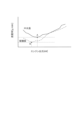
ただし、エンジン13は燃費性能の向上に寄与するデバイス(燃費デバイス)として、可変動弁装置(VTC)、排気還流装置(EGR)及びノッキングコントロール装置を備えており、これらが動作している場合と動作していない場合とでα線は異なる。例えば、エンジン13の冷機始動直後のようにVTCやEGRといった燃費デバイスが作動していない運転状態と、燃費デバイスが作動する暖機完了後の運転状態とではα線が異なる。冷機始動後かつ暖機完了前の、エンジン冷却液温度が中水温の状態と、暖機後の状態とを比較すると、図2に示す通り中水温における最も燃費率が低い動作点(図中の点A)の方が暖機後のそれ(図中の点B)よりも高エンジン出力になる。ここで、エンジン出力はエンジン回転速度と比例関係にある。 However, the engine 13 is equipped with a variable valve control system (VTC), an exhaust gas recirculation system (EGR), and a knocking control system as devices (fuel efficiency devices) that contribute to improving fuel efficiency, and when these devices are operating, The alpha rays are different depending on when it is not operating. For example, the alpha rays are different between an operating state in which fuel efficiency devices such as VTC and EGR are not operating, such as immediately after a cold start of the engine 13, and an operating state after warm-up, when the fuel efficiency devices are operating. Comparing the state where the engine coolant temperature is medium water temperature after a cold start and before completion of warm-up with the state after warm-up, as shown in Figure 2, the operating point with the lowest fuel efficiency at medium water temperature (in the figure Point A) has a higher engine output than that after warming up (point B in the diagram). Here, the engine output is proportional to the engine rotation speed.
上記の事情を勘案し、本実施形態ではエンジン13の暖機中における燃費性能の低下を抑制するために、燃費デバイスの作動/非作動に応じて、使用するα線を切り替えることとする。以下、本実施形態における中水温時のエンジン制御の詳細について説明する。 In consideration of the above circumstances, in this embodiment, in order to suppress a decrease in fuel efficiency while the engine 13 is being warmed up, the α rays to be used are switched depending on whether the fuel efficiency device is activated or not. Hereinafter, details of engine control at medium water temperature in this embodiment will be explained.
[中水温時のエンジン制御]
図3は、本実施形態にかかる中水温時のエンジン制御を行うためのα線演算部2A及びエンジン回転速度調停部3Aの制御ブロック図である。なお、図3には発電電力調停部及びエンジントルク調停部も示されているが、これらは本発明に特有の構成ではない。[Engine control at medium water temperature]
FIG. 3 is a control block diagram of the α-
α線演算部2Aは、発電電力調停部には定点出力を、エンジン回転速度調停部3Aにはα線回転速度と下限回転速度を、エンジントルク調停部にはα線トルクを、それぞれ出力する。
The α-
定点出力は、エンジン13の動作点におけるエンジン出力である。 The fixed point output is the engine output at the operating point of the engine 13.
α線回転速度はエンジン13をα線上の動作点で動作させるとした場合の、動作点におけるエンジン回転速度である。α線回転速度は、例えば中水温であれば図2の動作点Aにおけるエンジン出力に基づいて算出し、暖機後であれば図2の動作点Bにおけるエンジン出力に基づいて算出する。 The α-ray rotational speed is the engine rotational speed at an operating point when the engine 13 is operated at an operating point on the α-ray. For example, the α-ray rotation speed is calculated based on the engine output at the operating point A in FIG. 2 if the water temperature is medium, and is calculated based on the engine output at the operating point B in FIG. 2 if the temperature has been warmed up.
下限回転速度は、後述する演算により算出されるエンジン回転速度の下限値である。 The lower limit rotational speed is a lower limit value of the engine rotational speed calculated by a calculation described later.
α線トルクは、エンジン13をα線上の動作点で動作させるとした場合の、動作点におけるエンジントルクである。α線トルクは、例えばα線回転速度と同様に、α線上の動作点Aまたは動作点Bにおけるエンジン出力に基づいて算出する。 The α-ray torque is the engine torque at an operating point when the engine 13 is operated at an operating point on the α-ray. The α-ray torque is calculated based on the engine output at the operating point A or the operating point B on the α-ray, for example, similarly to the α-ray rotational speed.
本実施形態における特徴的な部分は、α線演算部2Aで下限回転速度を算出し、これをエンジン回転速度調停部3Aに出力する点である。エンジン回転速度調停部3Aにおける処理については後述する。
A characteristic feature of this embodiment is that the α-
図4は、α線演算部2Aにおいて下限回転速度を演算するための機能を制御ブロック図として表したものである。
FIG. 4 is a control block diagram showing a function for calculating the lower limit rotational speed in the α-
α線演算部2Aでは、エンジン冷却液温度に基づいて、中水温(つまり、燃費デバイスが作動しない運転状態)におけるα線または暖機後(つまり燃費デバイスが作動する運転状態)のα線のいずれを使用するかを判断する。中水温の場合はα線フラグをゼロ、暖機後の場合はα線フラグを1とする。エンジン状態判定部40は上記のα線フラグを読み込み、さらに、エンジン13が燃焼状態化非燃焼状態かを判定する。ここで、非燃焼状態にはアイドル運転も含まれる。エンジン状態判定部40は、非燃焼状態であれば状態フラグを1、燃焼状態であれば状態フラグをゼロとする。
Based on the engine coolant temperature, the α-
初回暖機判定部41は、今回のトリップで最初の暖機が完了しているか否かを判定する。なお、1トリップは、イグニッション・オン(つまりハイブリッドシステムの電源オン)からイグニッション・オフ(つまりハイブリッドシステムの電源オフ)までである。初回暖機判定部41は今回のトリップにおける最初の暖機が完了している場合は暖機完了フラグを1とし、完了前である場合は暖機完了フラグをゼロとする。
The first warm-up
フラグ判定部42は、状態フラグがゼロかつ暖機完了フラグがゼロという条件が成立するか否かを判定する。当該条件が成立する場合は、下限設定部43で下限回転速度の設定が決定(セット)される。また、下限設定部43は、トリップ開始時を意味する起動時リセットフラグが入力された場合には、上記の各フラグをクリアする。
The
下限回転速度がセットされた場合は、レート処理部44において、暖機完了後に下限回転速度によるエンジン回転速度の制限を解除する際のエンジン回転速度の変化速度を設定してから、セットされた旨及び当該変化速度をスイッチ45に出力する。
When the lower limit rotational speed is set, the
スイッチ45は、下限回転速度がセットされた場合は中水温下限回転速度を選択し、そうでない場合は回転速度として-9999を選択し、選択した値をエンジン回転速度調停部3Aに出力する。なお、-9999という回転速度は、下限回転速度を制限しないことを意味する。中水温下限回転速度は、例えば2000[rpm]前後とする。
The
図5は、エンジン回転速度調停部3Aにおいてエンジン回転速度を設定するための機能を制御ブロック図として表したものである。
FIG. 5 is a control block diagram showing a function for setting the engine rotation speed in the engine rotation
エンジン回転速度調停部3Aでは、3段階に分けてエンジン回転速度を決定する。
The engine rotation
第1段階では、α線に基づくエンジン回転速度と駆動力と車速によって定まる制限値により制限されるエンジン回転速度とを比較して、低い方を選択する。上記の制限値は、駆動力が小さいときや車速が低いときに、エンジンの作動音を目立たなくするためのエンジン回転速度の上限値である。本実施形態では、駆動力と車速とに応じて変化する制限値を予めマップ化されており、このマップに基づいて上記の制限値が定まる。 In the first stage, the engine rotation speed based on the alpha ray is compared with the engine rotation speed limited by the limit value determined by the driving force and the vehicle speed, and the lower one is selected. The above-mentioned limit value is the upper limit value of the engine rotation speed to make the operating sound of the engine less noticeable when the driving force is small or the vehicle speed is low. In this embodiment, the limit values that change depending on the driving force and vehicle speed are mapped in advance, and the above-mentioned limit values are determined based on this map.
第2段階では、上記で選択されたエンジン回転速度と、燃費要求下限回転速度と、チャージモード下限回転速度と、音振要求下限回転速度とを比較し、最も高いエンジン回転速度を選択する。燃費要求下限回転速度は、上述した中水温時におけるα線に基づいて定まる下限のエンジン回転速度である。 In the second stage, the engine rotation speed selected above, the fuel efficiency required lower limit rotation speed, the charge mode lower limit rotation speed, and the sound vibration required lower limit rotation speed are compared, and the highest engine rotation speed is selected. The fuel efficiency required lower limit rotational speed is the lower limit engine rotational speed determined based on the alpha rays at the above-mentioned medium water temperature.
チャージモード下限回転速度は、後述するチャージモードを実行する場合の下限のエンジン回転速度である。チャージモードとは、運転者のスイッチ操作に応じて実行する、バッテリ11のSOCを高めるための運転モードである。チャージモードを実行しない場合でも、バッテリ11のSOCが放電下限値まで低下すればエンジン13は発電量を増大させるよう制御されるが、チャージモードではバッテリ11のSOCが充電上限値以下であればSOCによらず発電量を増大させるためにエンジン回転速度が上昇する。 The charge mode lower limit rotational speed is the lower limit engine rotational speed when executing the charge mode, which will be described later. The charge mode is an operation mode for increasing the SOC of the battery 11, which is executed in response to a switch operation by the driver. Even when the charge mode is not executed, if the SOC of the battery 11 falls to the lower discharge limit, the engine 13 is controlled to increase the amount of power generation; however, in the charge mode, if the SOC of the battery 11 is lower than the upper limit, the SOC The engine speed increases to increase the amount of power generated regardless of the amount of power generated.
音振要求下限回転速度は、騒音及び振動を抑制する要求(いわゆる音振要求)を満足する下限のエンジン回転速度である。 The sound vibration required lower limit rotation speed is the lower limit engine rotation speed that satisfies the request to suppress noise and vibration (so-called sound vibration request).
第3段階では、暖房要求上限回転速度と、チャージモード上限回転速度と、SOC管理上限回転速度と、第2段階で選択されたエンジン回転速度と、を比較し、最も低いエンジン回転速度を選択する。 In the third stage, the heating request upper limit rotation speed, the charge mode upper limit rotation speed, the SOC management upper limit rotation speed, and the engine rotation speed selected in the second step are compared, and the lowest engine rotation speed is selected. .
暖房要求上限回転速度は、暖房要求を満足するようエンジン冷却液温度を上昇させるための制御である暖房制御を実行する際の上限のエンジン回転速度である。暖房制御を実行する際に、α線上の動作点で運転するとエンジン13の発熱量が低いため、エンジン冷却液の温度が上昇し難い。換言すると、エンジン冷却液温度を上昇させるためのエンジン13の運転時間が長くなる。そして、エンジン13の運転時間が長くなることにより、バッテリ11のSOCが過剰に上昇するおそれがある。そこで、暖房制御を実行する場合には、バッテリ11のSOCの過剰な上昇を防止するために、α線上の動作点よりも低い暖房要求上限回転速度を設定する。ただし、単にエンジン回転速度を低下させるだけでは燃費性能が悪化するおそれがあるので、バッテリ11のSOCの過剰な上昇を抑制しつつ、燃費性能の低下を抑制し得るエンジン回転速度を暖房要求上限回転速度として設定する。具体的には、エンジン13の仕様、バッテリ11の容量等に応じて設定する。 The heating request upper limit rotation speed is the upper limit engine rotation speed when executing heating control, which is control for increasing the engine coolant temperature so as to satisfy the heating request. When performing heating control, if the engine 13 is operated at an operating point on the alpha line, the heat generation amount of the engine 13 is low, so the temperature of the engine coolant is difficult to rise. In other words, the operating time of the engine 13 to increase the engine coolant temperature becomes longer. Then, as the operating time of the engine 13 becomes longer, the SOC of the battery 11 may increase excessively. Therefore, when performing heating control, in order to prevent the SOC of the battery 11 from increasing excessively, a heating request upper limit rotational speed is set lower than the operating point on the alpha line. However, simply reducing the engine rotation speed may deteriorate the fuel efficiency, so the engine rotation speed that can suppress the decrease in fuel efficiency while suppressing an excessive increase in the SOC of the battery 11 is set to the heating request upper limit rotation speed. Set as speed. Specifically, it is set according to the specifications of the engine 13, the capacity of the battery 11, etc.
SOC管理上限回転速度は、バッテリ11のSOCを放電可能下限値から充電可能上限値までの範囲に収めるための制御であるSOC管理制御を実行する際の、上限のエンジン回転速度である。SOC管理制御は、ハイブリッド車両において一般的に行われている制御であるため、説明を省略する。 The SOC management upper limit rotational speed is the upper limit engine rotational speed when performing SOC management control, which is control for keeping the SOC of the battery 11 within the range from the dischargeable lower limit value to the chargeable upper limit value. SOC management control is control that is commonly performed in hybrid vehicles, so a description thereof will be omitted.
上記の暖房要求上限回転速度、チャージモード上限回転速度及びSOC管理上限回転速度は、いずれもバッテリ11のSOCが過剰に上昇しないようにするためのエンジン回転速度である。すなわち、本実施形態では、仮に第2段階で燃費要求下限回転速度が選択された場合でも、第3段階においてバッテリ11のSOCが過剰に上昇しないようにするためのエンジン回転速度の方が低ければ、最終的に選択されるエンジン回転速度はバッテリ11のSOCが過剰に上昇しないようにするためのエンジン回転速度になる。なお、暖房要求上限回転速度はエンジン13の暖機が終了することにより変化する。 The heating request upper limit rotation speed, charge mode upper limit rotation speed, and SOC management upper limit rotation speed described above are all engine rotation speeds for preventing the SOC of the battery 11 from increasing excessively. That is, in the present embodiment, even if the fuel efficiency required lower limit rotational speed is selected in the second stage, if the engine rotational speed is lower in order to prevent the SOC of the battery 11 from increasing excessively in the third stage. The engine rotation speed that is finally selected is the engine rotation speed that prevents the SOC of the battery 11 from increasing excessively. Note that the heating request upper limit rotational speed changes as the warm-up of the engine 13 is completed.
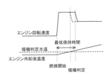
図6は、本実施形態の制御を実行した場合のタイミングチャートである。図中のエンジン出力のチャート及びエンジン仕事のチャートにおいて、実線は本実施形態の制御を実行した場合を示し、一点鎖線は比較例、具体的には上述した燃料効率の悪い動作点で暖機した場合を示している。なお、上述した通りエンジン出力とエンジン回転速度は比例関係にあるため、エンジン出力のチャートはエンジン回転速度に置き換えることができる。 FIG. 6 is a timing chart when the control of this embodiment is executed. In the engine output chart and engine work chart in the figure, the solid line shows the case where the control of this embodiment is executed, and the dashed-dotted line shows the comparative example, specifically, the case where the warm-up is performed at the operating point with poor fuel efficiency as described above. It shows the case. Note that, as described above, since the engine output and the engine rotation speed are in a proportional relationship, the engine output chart can be replaced with the engine rotation speed.
タイミングT1でエンジン13の暖機要求が発生し、これに応じてエンジン出力が増大する。このとき、本実施形態では中水温用のα線に基づくエンジン回転速度またはそれより高いエンジン回転速度でエンジン13が運転されるので、比較例よりも高いエンジン出力(エンジン回転速度)になる。暖機要求はエンジン冷却液温度が暖機閾値よりもやや低い温度になるタイミングT2まで続く。なお、タイミングT2において暖機閾値に達していないにもかかわらず暖機要求が終了しているのは、本実施形態の制御と並行して行われている他の制御によるものである。したがって、当該要求がなければ、暖機要求はエンジン冷却液温度が暖機閾値に達するまで継続する。また、タイミングT1以前からエンジンが作動しているが、これは本実施形態の制御とは別のルーチンにより設定される触媒暖機要求フラグに応じた作動である。 A request to warm up the engine 13 is generated at timing T1, and the engine output increases accordingly. At this time, in the present embodiment, the engine 13 is operated at an engine rotation speed based on the α ray for medium water temperature or a higher engine rotation speed, so that the engine output (engine rotation speed) is higher than that of the comparative example. The warm-up request continues until timing T2 when the engine coolant temperature becomes slightly lower than the warm-up threshold. Note that the reason why the warm-up request is completed even though the warm-up threshold value has not been reached at timing T2 is due to other control being performed in parallel with the control of this embodiment. Therefore, if there is no such request, the warm-up request continues until the engine coolant temperature reaches the warm-up threshold. Furthermore, although the engine has been operating before timing T1, this is an operation in response to a catalyst warm-up request flag that is set by a routine different from the control of this embodiment.
エンジン13はタイミングT2で停止した後、タイミングT3において再び作動する。これはバッテリ11のSOCコントロールに基づく要求、例えばチャージモードが選択されたことによる作動である。ここでも暖機は完了していないので、エンジン13はタイミングT1-T2と同じエンジン回転速度で作動する。 After the engine 13 stops at timing T2, it starts operating again at timing T3. This is an operation based on a request based on SOC control of the battery 11, for example, when the charge mode is selected. Since warm-up is not completed here as well, the engine 13 operates at the same engine rotation speed as at timing T1-T2.
そして、タイミングT4でエンジン冷却液温度が暖機閾値に到達する。しかし、エンジン出力は直ちには低下しない。これは、本実施形態では下限回転速度の最低保持時間を設けているからである。最低保持時間を設けるのは、例えばエンジンを始動した直後に暖機が完了した場合のように、エンジン回転速度が短時間で上下すると運転者が煩わしく感じるおそれがあるからである。具体的な最低保持時間は、適合等により設定するものであるが、例えば3-5秒程度とする。 Then, at timing T4, the engine coolant temperature reaches the warm-up threshold. However, the engine output does not decrease immediately. This is because the present embodiment provides a minimum holding time for the lower limit rotational speed. The reason why the minimum holding time is provided is that the driver may feel bothered if the engine rotational speed increases and decreases in a short period of time, for example, when warm-up is completed immediately after starting the engine. The specific minimum retention time is set based on suitability, etc., and is, for example, about 3 to 5 seconds.
最低保持時間が経過した後は、上述したレート処理部44で設定した変化速度でエンジン回転速度を低下させる。
After the minimum holding time has elapsed, the engine rotational speed is reduced at the rate of change set by the
また、タイミングT4でエンジン13の暖機が完了したら、初回暖機完了フラグが1になる。これにより、当該トリップ中にエンジン冷却液温度が再び暖機閾値を下回っても、本実施形態の制御は実行されない。これは、一度暖機が完了した後、エンジンが始動する度にエンジン回転速度が異なると運転者等に違和感を与えるおそれがあるからである。 Further, when the warm-up of the engine 13 is completed at timing T4, the initial warm-up completion flag becomes 1. As a result, even if the engine coolant temperature falls below the warm-up threshold again during the trip, the control of this embodiment is not executed. This is because if the engine rotational speed differs each time the engine is started after warm-up is completed, there is a risk that the driver or the like may feel uncomfortable.
ここで、エンジンの暖機が完了した後のエンジン回転速度の低下のさせ方について図7、図8を参照して説明する。 Here, a method for reducing the engine speed after the engine has been warmed up will be explained with reference to FIGS. 7 and 8.
図7は、最低保持時間の経過後に暖機が完了した場合を示している。図8は、最低保持時間の経過前に暖機が完了した場合を示している。 FIG. 7 shows a case where warm-up is completed after the minimum holding time has elapsed. FIG. 8 shows a case where warm-up is completed before the minimum holding time elapses.
最低保持時間の経過後に暖機が完了した場合には、図7に示す通り暖機が完了したタイミングでエンジン回転速度の下限回転速度による制限を解除し、エンジン回転速度を低下させる。一方、最低保持時間の経過前に暖機が完了した場合には、図8に示す通り最低保持時間が経過したタイミングでエンジン回転速度の下限回転速度による制限を解除し、エンジン回転速度を低下させる。なお、最低保持時間のカウントは、暖機運転を開始する毎に開始する。例えば、図8のタイミングT3でエンジン13を始動したときに、カウントを開始する。 When warm-up is completed after the minimum holding time has elapsed, as shown in FIG. 7, at the timing when warm-up is completed, the restriction of the engine rotation speed by the lower limit rotation speed is released, and the engine rotation speed is reduced. On the other hand, if warm-up is completed before the minimum holding time elapses, as shown in Figure 8, at the timing when the minimum holding time has elapsed, the restriction set by the lower limit rotational speed on the engine rotational speed is canceled and the engine rotational speed is reduced. . Note that counting of the minimum holding time starts every time the warm-up operation is started. For example, when the engine 13 is started at timing T3 in FIG. 8, counting is started.
エンジン回転速度を低下させる際の変化速度は、任意に設定することができる。例えば、急峻に低下することで運転者等に違和感を与えない程度の変化速度を適合等により設定する。 The rate of change when reducing the engine rotational speed can be set arbitrarily. For example, a speed of change is set by adaptation or the like so that a sudden decrease does not give a sense of discomfort to the driver or the like.
[効果]
以上の通り本実施形態によれば、走行用モータ8と、走行用モータ8に電力を供給するバッテリ11と、バッテリ11及び走行用モータ8に電力を供給可能な発電用のエンジン13と、を備えるハイブリッド車両の制御方法が提供される。この制御方法では、燃費性能の向上に寄与する燃費デバイスが作動しない運転状態では、燃費デバイスが作動する運転状態よりも高いエンジン回転速度で運転する。換言すると、燃費デバイスが作動しない運転状態では、燃費デバイスが作動する運転状態よりも、エンジン13の下限回転速度を高くする。これは、燃費デバイスが作動しない運転状態では、例えばノッキング回避等のために、作動する運転状態に比べてエンジン13の点火時期を遅角することになるところ、エンジン回転速度を高くすればノッキング発生の可能性が低くなるため、遅角量を小さくすることができるからである。本実施形態によれば、燃費デバイスが作動しない運転状態、換言するとエンジン冷却液温度が暖機閾値より低い運転状態における燃費性能を向上させることができる。[effect]
As described above, according to the present embodiment, the running motor 8, the battery 11 that supplies power to the running motor 8, and the power generation engine 13 that can supply power to the battery 11 and the running motor 8. A method for controlling a hybrid vehicle is provided. In this control method, the engine is operated at a higher rotational speed in an operating state in which a fuel efficiency device that contributes to improving fuel efficiency is not operating than in an operating state in which the fuel efficiency device is operating. In other words, in an operating state in which the fuel efficiency device does not operate, the lower limit rotational speed of the engine 13 is set higher than in an operating state in which the fuel efficiency device operates. This is because when the fuel efficiency device is not activated, the ignition timing of the engine 13 is retarded compared to when it is activated, to avoid knocking, for example, but if the engine speed is increased, knocking occurs. This is because the possibility of this decreases, so the amount of retardation can be reduced. According to this embodiment, fuel efficiency can be improved in a driving state in which the fuel efficiency device does not operate, in other words, in a driving state in which the engine coolant temperature is lower than the warm-up threshold.
本実施形態では、燃費デバイスが作動する運転状態であるか否かをエンジン冷却液温度に基づいて判断する。これにより、一般的なエンジン13が備える水温センサを用いて燃費デバイスが作動する運転状態であるか否かを判断できる。 In this embodiment, it is determined based on the engine coolant temperature whether or not the operating state is such that the fuel consumption device is activated. Thereby, it is possible to determine whether or not the operating state is such that the fuel consumption device is activated using the water temperature sensor included in the general engine 13.
本実施形態では、トリップ開始後に初回暖機が終了したら、当該トリップ中はエンジン冷却液温度が低下しても、燃費デバイスが作動する運転状態でのエンジン回転速度を維持する。これにより、運転者等に対してエンジン13が始動する度にエンジン回転速度が異なることによる違和感を与えることを防止できる。 In this embodiment, once the initial warm-up is completed after the start of a trip, the engine rotational speed is maintained during the trip even if the engine coolant temperature decreases in the operating state in which the fuel consumption device is activated. This can prevent the driver and the like from feeling uncomfortable due to the difference in engine rotational speed each time the engine 13 is started.
本実施形態では、燃費デバイスが作動しない運転状態でのエンジン回転速度を設定したら、予め設定した最低保持時間は当該エンジン回転速度を保持する。これにより、運転者等が、短時間でエンジン回転速度が上限することによる煩わしさを感じることを防止できる。 In this embodiment, once the engine rotation speed is set in an operating state in which the fuel consumption device does not operate, the engine rotation speed is maintained for a preset minimum holding time. This prevents the driver and the like from feeling bothered by the engine speed reaching its upper limit in a short period of time.
本実施形態では、バッテリ11の充電率(SOC)の過剰な上昇を抑制するための上限エンジン回転速度と、燃費デバイスが作動しない運転状態での下限回転速度と、を比較し、低い方のエンジン回転速度で運転する。これにより、バッテリ11のSOCの過剰な上昇を抑制できる。 In this embodiment, the upper limit engine rotation speed for suppressing an excessive increase in the charging rate (SOC) of the battery 11 is compared with the lower limit rotation speed in a driving state in which the fuel consumption device does not operate, and the lower limit engine rotation speed is compared. Drive at rotational speed. Thereby, an excessive increase in the SOC of the battery 11 can be suppressed.
本実施形態では、上限エンジン回転速度は、暖房要求に応じてエンジン冷却液温度を上昇させるためにエンジン13を運転する際の、バッテリ11のSOCの過剰な上昇を抑制するためのエンジン回転速度である。これにより、エンジン冷却液温度が低い運転状態であっても、バッテリ11のSOCの過剰な上昇を抑制しつつ、暖房要求を満足することができる。 In this embodiment, the upper limit engine rotation speed is an engine rotation speed for suppressing an excessive increase in the SOC of the battery 11 when the engine 13 is operated to increase the engine coolant temperature in response to a heating request. be. Thereby, even in an operating state where the engine coolant temperature is low, the heating request can be satisfied while suppressing an excessive increase in the SOC of the battery 11.
以上、本発明の実施形態について説明したが、上記実施形態は本発明の適用例の一部を示したに過ぎず、本発明の技術的範囲を上記実施形態の具体的構成に限定する趣旨ではない。 Although the embodiments of the present invention have been described above, the above embodiments merely show a part of the application examples of the present invention, and are not intended to limit the technical scope of the present invention to the specific configurations of the above embodiments. do not have.
Claims (7)
前記エンジンの運転状態には前記燃費デバイスが作動する運転状態と作動しない運転状態とがあり、
前記燃費デバイスが作動する運転状態か否かをエンジン冷却液温度に基づいて判断し、
前記燃費デバイスが作動しない運転状態では前記燃費デバイスが作動しない運転状態における燃費最適線上の動作点で前記エンジンを作動させ、前記燃費デバイスが作動する運転状態では前記燃費デバイスが作動する運転状態における燃費最適線上の動作点で前記エンジンを作動させ、かつ、
前記燃費デバイスが作動しない運転状態では、前記燃費デバイスが作動する運転状態よりも高いエンジン回転速度で前記エンジンを運転する、ハイブリッド車両の制御方法。 A traction motor, a battery for supplying power to the traction motor, a generator engine capable of supplying power to the battery and the traction motor, and a device included in the engine for improving fuel efficiency. A method for controlling a hybrid vehicle comprising: a fuel efficiency device that contributes to fuel consumption;
The operating state of the engine includes an operating state in which the fuel efficiency device operates and an operating state in which the fuel efficiency device does not operate.
Determining whether or not the operating state is such that the fuel efficiency device operates based on the engine coolant temperature;
In a driving state in which the fuel efficiency device does not operate, the engine is operated at an operating point on the optimum fuel efficiency line in the driving state in which the fuel efficiency device does not operate, and in a driving state in which the fuel efficiency device operates, the fuel efficiency in the driving state in which the fuel efficiency device operates. operating the engine at an operating point on the optimum line, and
A method for controlling a hybrid vehicle, wherein the engine is operated at a higher engine rotational speed in a driving state in which the fuel efficiency device is not activated than in a driving state in which the fuel efficiency device is activated.
トリップ開始後に初回暖機が終了したら、当該トリップ中は前記エンジン冷却液温度が低下しても、前記燃費デバイスが作動する運転状態での前記エンジン回転速度を維持する、ハイブリッド車両の制御方法。 The method for controlling a hybrid vehicle according to claim 1,
A method for controlling a hybrid vehicle, wherein, after initial warm-up is completed after the start of a trip, the engine rotational speed is maintained in a driving state in which the fuel consumption device is activated even if the temperature of the engine coolant decreases during the trip.
前記燃費デバイスが作動しない運転状態での前記エンジン回転速度を設定したら、予め設定した最低保持時間は当該エンジン回転速度を保持する、ハイブリッド車両の制御方法。 The method for controlling a hybrid vehicle according to claim 1 or 2,
A control method for a hybrid vehicle, wherein, after setting the engine rotation speed in a driving state in which the fuel efficiency device does not operate, the engine rotation speed is maintained for a preset minimum holding time.
前記バッテリの充電率の過剰な上昇を抑制するための上限エンジン回転速度と、前記燃費デバイスが作動しない運転状態での前記エンジン回転速度と、を比較し、低い方のエンジン回転速度で運転する、ハイブリッド車両の制御方法。 The method for controlling a hybrid vehicle according to any one of claims 1 to 3,
Comparing an upper limit engine rotation speed for suppressing an excessive increase in the charging rate of the battery and the engine rotation speed in an operating state in which the fuel efficiency device does not operate, and operating at the lower engine rotation speed. How to control a hybrid vehicle.
前記上限エンジン回転速度は、暖房要求に応じてエンジン冷却液温度を上昇させるために前記エンジンを運転する際の、前記バッテリの充電率の過剰な上昇を抑制するためのエンジン回転速度である、ハイブリッド車両の制御方法。 The method for controlling a hybrid vehicle according to claim 4,
The upper limit engine rotation speed is an engine rotation speed for suppressing an excessive increase in the charging rate of the battery when the engine is operated to increase the engine coolant temperature in response to a heating request. How to control the vehicle.
前記ハイブリッド車両は、シリーズハイブリッド車両として構成されている、ハイブリッド車両の制御方法。 The method for controlling a hybrid vehicle according to claim 1,
A method for controlling a hybrid vehicle, wherein the hybrid vehicle is configured as a series hybrid vehicle.
前記エンジンの運転状態には前記燃費デバイスが作動する運転状態と作動しない運転状態とがあり、
前記走行用モータ、前記バッテリの充電率及び前記エンジンを制御する制御部を備え、
前記制御部は、
前記燃費デバイスが作動する運転状態か否かをエンジン冷却液温度に基づいて判断し、前記燃費デバイスが作動しない運転状態では前記燃費デバイスが作動しない運転状態における燃費最適線上の動作点で前記エンジンを作動させ、前記燃費デバイスが作動する運転状態では前記燃費デバイスが作動する運転状態における燃費最適線上の動作点で前記エンジンを作動させ、かつ、前記燃費デバイスが作動しない運転状態では、前記燃費デバイスが作動する運転状態よりも高いエンジン回転速度で前記エンジンを運転する、ハイブリッド車両の制御装置。 A traction motor, a battery for supplying power to the traction motor, a generator engine capable of supplying power to the battery and the traction motor, and a device included in the engine for improving fuel efficiency. A control device for a hybrid vehicle comprising: a fuel efficiency device that contributes to fuel consumption;
The operating state of the engine includes an operating state in which the fuel efficiency device operates and an operating state in which the fuel efficiency device does not operate.
comprising a control unit that controls the driving motor, the charging rate of the battery, and the engine;
The control unit includes:
It is determined based on the engine coolant temperature whether or not the fuel efficiency device is in an operating state, and in the operating state in which the fuel efficiency device is not operating, the engine is operated at an operating point on the fuel efficiency optimum line in the operating state in which the fuel efficiency device is not operating. and in an operating state in which the fuel efficiency device operates, the engine is operated at an operating point on the optimum fuel efficiency line in the operating state in which the fuel efficiency device operates, and in an operating state in which the fuel efficiency device does not operate, the fuel efficiency device operates. A control device for a hybrid vehicle that operates the engine at a higher engine rotational speed than in an operating state.
Applications Claiming Priority (3)
| Application Number | Priority Date | Filing Date | Title |
|---|---|---|---|
| JP2020022144 | 2020-06-04 | ||
| JPPCT/JP2020/022144 | 2020-06-04 | ||
| PCT/JP2020/024405 WO2021245953A1 (en) | 2020-06-04 | 2020-06-22 | Hybrid vehicle control method and hybrid vehicle control device |
Publications (3)
| Publication Number | Publication Date |
|---|---|
| JPWO2021245953A1 JPWO2021245953A1 (en) | 2021-12-09 |
| JPWO2021245953A5 JPWO2021245953A5 (en) | 2023-02-14 |
| JP7367869B2 true JP7367869B2 (en) | 2023-10-24 |
Family
ID=78830764
Family Applications (1)
| Application Number | Title | Priority Date | Filing Date |
|---|---|---|---|
| JP2022528408A Active JP7367869B2 (en) | 2020-06-04 | 2020-06-22 | Hybrid vehicle control method and hybrid vehicle control device |
Country Status (6)
| Country | Link |
|---|---|
| US (1) | US20230227020A1 (en) |
| EP (1) | EP4163171A4 (en) |
| JP (1) | JP7367869B2 (en) |
| CN (1) | CN115884907A (en) |
| MX (1) | MX2022015135A (en) |
| WO (1) | WO2021245953A1 (en) |
Citations (7)
| Publication number | Priority date | Publication date | Assignee | Title |
|---|---|---|---|---|
| JP2004143982A (en) | 2002-10-23 | 2004-05-20 | Suzuki Motor Corp | Engine speed control device |
| JP2004278340A (en) | 2003-03-13 | 2004-10-07 | Nissan Motor Co Ltd | Control device of hybrid vehicle |
| JP2008168805A (en) | 2007-01-12 | 2008-07-24 | Toyota Motor Corp | Vehicle and its control method |
| JP2010100103A (en) | 2008-10-21 | 2010-05-06 | Toyota Motor Corp | Hybrid car and control method for the same |
| JP2010241380A (en) | 2009-04-09 | 2010-10-28 | Toyota Motor Corp | Hybrid vehicle and method for controlling the same |
| WO2011046123A1 (en) | 2009-10-14 | 2011-04-21 | 日産自動車株式会社 | Control apparatus for hybrid vehicle |
| JP2014100944A (en) | 2012-11-16 | 2014-06-05 | Toyota Motor Corp | Control system for hybrid vehicle and hybrid vehicle |
-
2020
- 2020-06-22 CN CN202080101645.8A patent/CN115884907A/en active Pending
- 2020-06-22 WO PCT/JP2020/024405 patent/WO2021245953A1/en unknown
- 2020-06-22 JP JP2022528408A patent/JP7367869B2/en active Active
- 2020-06-22 EP EP20938998.0A patent/EP4163171A4/en active Pending
- 2020-06-22 US US17/928,792 patent/US20230227020A1/en active Pending
- 2020-06-22 MX MX2022015135A patent/MX2022015135A/en unknown
Patent Citations (7)
| Publication number | Priority date | Publication date | Assignee | Title |
|---|---|---|---|---|
| JP2004143982A (en) | 2002-10-23 | 2004-05-20 | Suzuki Motor Corp | Engine speed control device |
| JP2004278340A (en) | 2003-03-13 | 2004-10-07 | Nissan Motor Co Ltd | Control device of hybrid vehicle |
| JP2008168805A (en) | 2007-01-12 | 2008-07-24 | Toyota Motor Corp | Vehicle and its control method |
| JP2010100103A (en) | 2008-10-21 | 2010-05-06 | Toyota Motor Corp | Hybrid car and control method for the same |
| JP2010241380A (en) | 2009-04-09 | 2010-10-28 | Toyota Motor Corp | Hybrid vehicle and method for controlling the same |
| WO2011046123A1 (en) | 2009-10-14 | 2011-04-21 | 日産自動車株式会社 | Control apparatus for hybrid vehicle |
| JP2014100944A (en) | 2012-11-16 | 2014-06-05 | Toyota Motor Corp | Control system for hybrid vehicle and hybrid vehicle |
Also Published As
| Publication number | Publication date |
|---|---|
| JPWO2021245953A1 (en) | 2021-12-09 |
| WO2021245953A1 (en) | 2021-12-09 |
| CN115884907A (en) | 2023-03-31 |
| EP4163171A1 (en) | 2023-04-12 |
| US20230227020A1 (en) | 2023-07-20 |
| EP4163171A4 (en) | 2023-11-29 |
| MX2022015135A (en) | 2023-01-04 |
Similar Documents
| Publication | Publication Date | Title |
|---|---|---|
| JP5321321B2 (en) | Battery charge control device and battery charge control method | |
| WO2010100748A1 (en) | Hybrid vehicle control device and control method | |
| JP3933096B2 (en) | Battery control device and control method mounted on vehicle | |
| JP2003009305A (en) | Controller for hybrid vehicle | |
| JP4508281B2 (en) | Battery control apparatus and storage battery charge / discharge control method | |
| JP2008049877A (en) | Battery control device | |
| JP5321204B2 (en) | Control device for hybrid vehicle | |
| JP5794029B2 (en) | Control device for hybrid vehicle | |
| JP3951847B2 (en) | Vehicle control device, control method, program for realizing the control method, and recording medium recording the program | |
| JP5692140B2 (en) | Drive control device | |
| JP3214285B2 (en) | Power generation control method and device in series hybrid vehicle | |
| JP3211595B2 (en) | Hybrid electric vehicle | |
| JP4086053B2 (en) | Control device for hybrid vehicle | |
| KR101114383B1 (en) | Method for controlling of hybrid electric vehicle | |
| JP3956812B2 (en) | Engine cooling control device and vehicle equipped with the cooling control device | |
| JP7367869B2 (en) | Hybrid vehicle control method and hybrid vehicle control device | |
| JP3455145B2 (en) | Hybrid vehicle fan control device | |
| JP6409735B2 (en) | Control device for hybrid vehicle | |
| JP5278963B2 (en) | Vehicle control device | |
| JP2009100542A (en) | Controller of rotating electrical machine, its control method, program achieving the method by computer and recording medium recording program | |
| JP6881366B2 (en) | Vehicle control system | |
| JP6224897B2 (en) | Vehicle travel control device | |
| JP3731884B2 (en) | Vehicle air conditioning system | |
| KR100792922B1 (en) | Engine start control method of hybrid electric vehicles | |
| JP2003176737A (en) | Vehicle controller |
Legal Events
| Date | Code | Title | Description |
|---|---|---|---|
| A521 | Request for written amendment filed |
Free format text: JAPANESE INTERMEDIATE CODE: A523 Effective date: 20221201 |
|
| A621 | Written request for application examination |
Free format text: JAPANESE INTERMEDIATE CODE: A621 Effective date: 20221201 |
|
| A131 | Notification of reasons for refusal |
Free format text: JAPANESE INTERMEDIATE CODE: A131 Effective date: 20230613 |
|
| A521 | Request for written amendment filed |
Free format text: JAPANESE INTERMEDIATE CODE: A523 Effective date: 20230810 |
|
| TRDD | Decision of grant or rejection written | ||
| A01 | Written decision to grant a patent or to grant a registration (utility model) |
Free format text: JAPANESE INTERMEDIATE CODE: A01 Effective date: 20230912 |
|
| A61 | First payment of annual fees (during grant procedure) |
Free format text: JAPANESE INTERMEDIATE CODE: A61 Effective date: 20230925 |
|
| R151 | Written notification of patent or utility model registration |
Ref document number: 7367869 Country of ref document: JP Free format text: JAPANESE INTERMEDIATE CODE: R151 |