JP7367146B2 - Collapsible fiber matrix storage for e-vaping devices - Google Patents
Collapsible fiber matrix storage for e-vaping devices Download PDFInfo
- Publication number
- JP7367146B2 JP7367146B2 JP2022128792A JP2022128792A JP7367146B2 JP 7367146 B2 JP7367146 B2 JP 7367146B2 JP 2022128792 A JP2022128792 A JP 2022128792A JP 2022128792 A JP2022128792 A JP 2022128792A JP 7367146 B2 JP7367146 B2 JP 7367146B2
- Authority
- JP
- Japan
- Prior art keywords
- fibers
- reservoir
- millimeters
- length
- vaping device
- Prior art date
- Legal status (The legal status is an assumption and is not a legal conclusion. Google has not performed a legal analysis and makes no representation as to the accuracy of the status listed.)
- Active
Links
Images


Classifications
-
- A—HUMAN NECESSITIES
- A61—MEDICAL OR VETERINARY SCIENCE; HYGIENE
- A61M—DEVICES FOR INTRODUCING MEDIA INTO, OR ONTO, THE BODY; DEVICES FOR TRANSDUCING BODY MEDIA OR FOR TAKING MEDIA FROM THE BODY; DEVICES FOR PRODUCING OR ENDING SLEEP OR STUPOR
- A61M15/00—Inhalators
- A61M15/06—Inhaling appliances shaped like cigars, cigarettes or pipes
-
- A—HUMAN NECESSITIES
- A24—TOBACCO; CIGARS; CIGARETTES; SIMULATED SMOKING DEVICES; SMOKERS' REQUISITES
- A24F—SMOKERS' REQUISITES; MATCH BOXES; SIMULATED SMOKING DEVICES
- A24F40/00—Electrically operated smoking devices; Component parts thereof; Manufacture thereof; Maintenance or testing thereof; Charging means specially adapted therefor
- A24F40/40—Constructional details, e.g. connection of cartridges and battery parts
- A24F40/42—Cartridges or containers for inhalable precursors
-
- A—HUMAN NECESSITIES
- A24—TOBACCO; CIGARS; CIGARETTES; SIMULATED SMOKING DEVICES; SMOKERS' REQUISITES
- A24B—MANUFACTURE OR PREPARATION OF TOBACCO FOR SMOKING OR CHEWING; TOBACCO; SNUFF
- A24B15/00—Chemical features or treatment of tobacco; Tobacco substitutes, e.g. in liquid form
- A24B15/10—Chemical features of tobacco products or tobacco substitutes
- A24B15/16—Chemical features of tobacco products or tobacco substitutes of tobacco substitutes
- A24B15/167—Chemical features of tobacco products or tobacco substitutes of tobacco substitutes in liquid or vaporisable form, e.g. liquid compositions for electronic cigarettes
-
- A—HUMAN NECESSITIES
- A24—TOBACCO; CIGARS; CIGARETTES; SIMULATED SMOKING DEVICES; SMOKERS' REQUISITES
- A24D—CIGARS; CIGARETTES; TOBACCO SMOKE FILTERS; MOUTHPIECES FOR CIGARS OR CIGARETTES; MANUFACTURE OF TOBACCO SMOKE FILTERS OR MOUTHPIECES
- A24D1/00—Cigars; Cigarettes
- A24D1/002—Cigars; Cigarettes with additives, e.g. for flavouring
-
- A—HUMAN NECESSITIES
- A24—TOBACCO; CIGARS; CIGARETTES; SIMULATED SMOKING DEVICES; SMOKERS' REQUISITES
- A24F—SMOKERS' REQUISITES; MATCH BOXES; SIMULATED SMOKING DEVICES
- A24F31/00—Pipe-spills; Devices for splitting matches
-
- A—HUMAN NECESSITIES
- A24—TOBACCO; CIGARS; CIGARETTES; SIMULATED SMOKING DEVICES; SMOKERS' REQUISITES
- A24F—SMOKERS' REQUISITES; MATCH BOXES; SIMULATED SMOKING DEVICES
- A24F40/00—Electrically operated smoking devices; Component parts thereof; Manufacture thereof; Maintenance or testing thereof; Charging means specially adapted therefor
- A24F40/40—Constructional details, e.g. connection of cartridges and battery parts
- A24F40/44—Wicks
-
- A—HUMAN NECESSITIES
- A24—TOBACCO; CIGARS; CIGARETTES; SIMULATED SMOKING DEVICES; SMOKERS' REQUISITES
- A24F—SMOKERS' REQUISITES; MATCH BOXES; SIMULATED SMOKING DEVICES
- A24F40/00—Electrically operated smoking devices; Component parts thereof; Manufacture thereof; Maintenance or testing thereof; Charging means specially adapted therefor
- A24F40/50—Control or monitoring
- A24F40/51—Arrangement of sensors
-
- A—HUMAN NECESSITIES
- A24—TOBACCO; CIGARS; CIGARETTES; SIMULATED SMOKING DEVICES; SMOKERS' REQUISITES
- A24F—SMOKERS' REQUISITES; MATCH BOXES; SIMULATED SMOKING DEVICES
- A24F40/00—Electrically operated smoking devices; Component parts thereof; Manufacture thereof; Maintenance or testing thereof; Charging means specially adapted therefor
- A24F40/50—Control or monitoring
- A24F40/53—Monitoring, e.g. fault detection
-
- A—HUMAN NECESSITIES
- A24—TOBACCO; CIGARS; CIGARETTES; SIMULATED SMOKING DEVICES; SMOKERS' REQUISITES
- A24F—SMOKERS' REQUISITES; MATCH BOXES; SIMULATED SMOKING DEVICES
- A24F40/00—Electrically operated smoking devices; Component parts thereof; Manufacture thereof; Maintenance or testing thereof; Charging means specially adapted therefor
- A24F40/90—Arrangements or methods specially adapted for charging batteries thereof
- A24F40/95—Arrangements or methods specially adapted for charging batteries thereof structurally associated with cases
-
- A—HUMAN NECESSITIES
- A61—MEDICAL OR VETERINARY SCIENCE; HYGIENE
- A61M—DEVICES FOR INTRODUCING MEDIA INTO, OR ONTO, THE BODY; DEVICES FOR TRANSDUCING BODY MEDIA OR FOR TAKING MEDIA FROM THE BODY; DEVICES FOR PRODUCING OR ENDING SLEEP OR STUPOR
- A61M11/00—Sprayers or atomisers specially adapted for therapeutic purposes
- A61M11/04—Sprayers or atomisers specially adapted for therapeutic purposes operated by the vapour pressure of the liquid to be sprayed or atomised
- A61M11/041—Sprayers or atomisers specially adapted for therapeutic purposes operated by the vapour pressure of the liquid to be sprayed or atomised using heaters
- A61M11/042—Sprayers or atomisers specially adapted for therapeutic purposes operated by the vapour pressure of the liquid to be sprayed or atomised using heaters electrical
-
- A—HUMAN NECESSITIES
- A61—MEDICAL OR VETERINARY SCIENCE; HYGIENE
- A61M—DEVICES FOR INTRODUCING MEDIA INTO, OR ONTO, THE BODY; DEVICES FOR TRANSDUCING BODY MEDIA OR FOR TAKING MEDIA FROM THE BODY; DEVICES FOR PRODUCING OR ENDING SLEEP OR STUPOR
- A61M16/00—Devices for influencing the respiratory system of patients by gas treatment, e.g. mouth-to-mouth respiration; Tracheal tubes
- A61M16/0003—Accessories therefor, e.g. sensors, vibrators, negative pressure
-
- H—ELECTRICITY
- H05—ELECTRIC TECHNIQUES NOT OTHERWISE PROVIDED FOR
- H05B—ELECTRIC HEATING; ELECTRIC LIGHT SOURCES NOT OTHERWISE PROVIDED FOR; CIRCUIT ARRANGEMENTS FOR ELECTRIC LIGHT SOURCES, IN GENERAL
- H05B1/00—Details of electric heating devices
- H05B1/02—Automatic switching arrangements specially adapted to apparatus ; Control of heating devices
- H05B1/0202—Switches
-
- H—ELECTRICITY
- H05—ELECTRIC TECHNIQUES NOT OTHERWISE PROVIDED FOR
- H05B—ELECTRIC HEATING; ELECTRIC LIGHT SOURCES NOT OTHERWISE PROVIDED FOR; CIRCUIT ARRANGEMENTS FOR ELECTRIC LIGHT SOURCES, IN GENERAL
- H05B1/00—Details of electric heating devices
- H05B1/02—Automatic switching arrangements specially adapted to apparatus ; Control of heating devices
- H05B1/0227—Applications
- H05B1/0297—Heating of fluids for non specified applications
-
- H—ELECTRICITY
- H05—ELECTRIC TECHNIQUES NOT OTHERWISE PROVIDED FOR
- H05B—ELECTRIC HEATING; ELECTRIC LIGHT SOURCES NOT OTHERWISE PROVIDED FOR; CIRCUIT ARRANGEMENTS FOR ELECTRIC LIGHT SOURCES, IN GENERAL
- H05B3/00—Ohmic-resistance heating
- H05B3/40—Heating elements having the shape of rods or tubes
- H05B3/42—Heating elements having the shape of rods or tubes non-flexible
- H05B3/44—Heating elements having the shape of rods or tubes non-flexible heating conductor arranged within rods or tubes of insulating material
-
- A—HUMAN NECESSITIES
- A24—TOBACCO; CIGARS; CIGARETTES; SIMULATED SMOKING DEVICES; SMOKERS' REQUISITES
- A24F—SMOKERS' REQUISITES; MATCH BOXES; SIMULATED SMOKING DEVICES
- A24F40/00—Electrically operated smoking devices; Component parts thereof; Manufacture thereof; Maintenance or testing thereof; Charging means specially adapted therefor
- A24F40/10—Devices using liquid inhalable precursors
-
- A—HUMAN NECESSITIES
- A61—MEDICAL OR VETERINARY SCIENCE; HYGIENE
- A61M—DEVICES FOR INTRODUCING MEDIA INTO, OR ONTO, THE BODY; DEVICES FOR TRANSDUCING BODY MEDIA OR FOR TAKING MEDIA FROM THE BODY; DEVICES FOR PRODUCING OR ENDING SLEEP OR STUPOR
- A61M16/00—Devices for influencing the respiratory system of patients by gas treatment, e.g. mouth-to-mouth respiration; Tracheal tubes
- A61M16/0003—Accessories therefor, e.g. sensors, vibrators, negative pressure
- A61M2016/0015—Accessories therefor, e.g. sensors, vibrators, negative pressure inhalation detectors
- A61M2016/0018—Accessories therefor, e.g. sensors, vibrators, negative pressure inhalation detectors electrical
- A61M2016/0024—Accessories therefor, e.g. sensors, vibrators, negative pressure inhalation detectors electrical with an on-off output signal, e.g. from a switch
-
- A—HUMAN NECESSITIES
- A61—MEDICAL OR VETERINARY SCIENCE; HYGIENE
- A61M—DEVICES FOR INTRODUCING MEDIA INTO, OR ONTO, THE BODY; DEVICES FOR TRANSDUCING BODY MEDIA OR FOR TAKING MEDIA FROM THE BODY; DEVICES FOR PRODUCING OR ENDING SLEEP OR STUPOR
- A61M2205/00—General characteristics of the apparatus
- A61M2205/12—General characteristics of the apparatus with interchangeable cassettes forming partially or totally the fluid circuit
- A61M2205/123—General characteristics of the apparatus with interchangeable cassettes forming partially or totally the fluid circuit with incorporated reservoirs
-
- A—HUMAN NECESSITIES
- A61—MEDICAL OR VETERINARY SCIENCE; HYGIENE
- A61M—DEVICES FOR INTRODUCING MEDIA INTO, OR ONTO, THE BODY; DEVICES FOR TRANSDUCING BODY MEDIA OR FOR TAKING MEDIA FROM THE BODY; DEVICES FOR PRODUCING OR ENDING SLEEP OR STUPOR
- A61M2205/00—General characteristics of the apparatus
- A61M2205/36—General characteristics of the apparatus related to heating or cooling
- A61M2205/3653—General characteristics of the apparatus related to heating or cooling by Joule effect, i.e. electric resistance
-
- A—HUMAN NECESSITIES
- A61—MEDICAL OR VETERINARY SCIENCE; HYGIENE
- A61M—DEVICES FOR INTRODUCING MEDIA INTO, OR ONTO, THE BODY; DEVICES FOR TRANSDUCING BODY MEDIA OR FOR TAKING MEDIA FROM THE BODY; DEVICES FOR PRODUCING OR ENDING SLEEP OR STUPOR
- A61M2205/00—General characteristics of the apparatus
- A61M2205/58—Means for facilitating use, e.g. by people with impaired vision
- A61M2205/587—Lighting arrangements
-
- A—HUMAN NECESSITIES
- A61—MEDICAL OR VETERINARY SCIENCE; HYGIENE
- A61M—DEVICES FOR INTRODUCING MEDIA INTO, OR ONTO, THE BODY; DEVICES FOR TRANSDUCING BODY MEDIA OR FOR TAKING MEDIA FROM THE BODY; DEVICES FOR PRODUCING OR ENDING SLEEP OR STUPOR
- A61M2205/00—General characteristics of the apparatus
- A61M2205/82—Internal energy supply devices
- A61M2205/8206—Internal energy supply devices battery-operated
Description
例示的な実施形態は、概してeベイピング装置のためのプレベイパー製剤貯蔵部、加熱式プレベイパー製剤の量を増加させるように構成された貯蔵部、およびeベイピング装置カートリッジの実用的な寿命を増加させる方法に関する。 Exemplary embodiments generally provide a pre-vapor formulation reservoir for an e-vaping device, a reservoir configured to increase the amount of heated pre-vapor formulation, and a method of increasing the useful life of an e-vaping device cartridge. Regarding.
電子ベイピング装置はプレベイパー製剤をベイパーへと気化するために使用され、成人eベイピング装置使用者がこの装置の一つ以上の出口を通してベイパーを吸い込むようにする。これらの電子ベイピング装置は、eベイピング装置と呼ばれてもよい。eベイピング装置は典型的に、電源セクションおよびカートリッジなど、いくつかのeベイピング要素を含みうる。電源セクションは、電池を含んでもよく、カートリッジはプレベイパー製剤を貯蔵できる貯蔵部に加えてヒーターを含んでもよい。貯蔵部は、内管または貯蔵部の一部の周りに巻き付けたコットンまたはセルロースガーゼまたは他の繊維材料を含んでもよい。カートリッジは、芯を介してプレベイパー製剤と連通するヒーターを含んでもよく、ヒーターはベイパーを生成するために芯でプレベイパー製剤を加熱するよう構成される。プレベイパー製剤は、ベイパー形成体と同様にニコチンの量を含んでもよく、あるいは水、酸、風味剤、および芳香剤のうちの少なくとも一つを含んでもよい。プレベイパー製剤は、ベイパーへと変わる材料または材料の組み合わせを含んでもよい。例えば、プレベイパー製剤は、水、ビーズ、溶媒、活性成分、エタノール、植物抽出物、天然または人工風味、グリセリンおよびプロピレングリコールのうちの少なくとも一つなどのベイパー形成体、ならびにその組み合わせ(ただしこれらに限定されない)を含む、液体製剤、固体製剤、またはゲル製剤のうちの少なくとも一つを含んでもよい。 Electronic vaping devices are used to vaporize pre-vapor formulations into vapor, which an adult e-vaping device user inhales through one or more outlets of the device. These electronic vaping devices may be referred to as e-vaping devices. An e-vaping device may typically include several e-vaping elements, such as a power supply section and a cartridge. The power section may include a battery and the cartridge may include a heater in addition to a reservoir in which the pre-vapor formulation can be stored. The reservoir may include cotton or cellulose gauze or other fibrous material wrapped around a portion of the inner tube or reservoir. The cartridge may include a heater in communication with the pre-vapor formulation via the wick, the heater being configured to heat the pre-vapor formulation at the wick to produce vapor. The prevapor formulation may contain the same amount of nicotine as the vapor former, or may contain at least one of water, acid, flavor, and aroma. Pre-vapor formulations may include materials or combinations of materials that convert into vapor. For example, pre-vapor formulations include vapor formers such as, but not limited to, water, beads, solvents, active ingredients, ethanol, plant extracts, natural or artificial flavors, at least one of glycerin and propylene glycol, and combinations thereof. may include at least one of a liquid formulation, a solid formulation, or a gel formulation.
eベイピング装置では、貯蔵部に含まれるプレベイパー製剤は自由流動性形態であってもよく、プレベイパー製剤を囲む円筒形ガーゼと共に所定位置に保持されてもよく、その結果、プレベイパー製剤の量が浪費され得る。例えば、約40パーセントのプレベイパー製剤は、貯蔵部に残ることができ、eベイピング装置の動作中に加熱されるために芯に移されない。 In an e-vaping device, the pre-vapor formulation contained in the reservoir may be in free-flowing form and may be held in place with a cylindrical gauze surrounding the pre-vapor formulation, so that the amount of pre-vapor formulation is not wasted. obtain. For example, approximately 40 percent of the pre-vapor formulation may remain in the reservoir and not be transferred to the wick to be heated during operation of the e-vaping device.
少なくとも一つの例示的な実施形態は、プレベイパー製剤溶液を貯蔵するよう構成された不溶性ポリマー繊維を含む、eベイピング装置のカートリッジに関する。 At least one exemplary embodiment relates to an e-vaping device cartridge that includes an insoluble polymeric fiber configured to store a prevapor formulation solution.
少なくとも一つの例示的な実施形態では、eベイピング装置の貯蔵部は、内管または貯蔵部の一部の周りに巻かれた内側および外側の繊維材料を含んでもよい。例えば、コットンガーゼおよび不溶性ポリマー繊維のうちの少なくとも一つのような、例えば、内側繊維材料および外側繊維材料は、プレベイパー製剤を貯蔵することができる。例えば、ポリマー繊維は、プレベイパー製剤の様々な成分と化学的に適合性があり得、例えば、ポリマー繊維は、プレベイパー製剤の様々な成分の存在中で、実質的に化学的に不活性であり得る。ポリマー繊維は、例えば、エチレン酢酸ビニル外筒と共に、例えば、ポリプロピレンコアを含んでもよい。ポリマー繊維は、プレベイパー製剤溶液中に実質的に均等に分配されるように、プレベイパー製剤溶液に加えて攪拌してもよい。 In at least one exemplary embodiment, the reservoir of an e-vaping device may include inner and outer fibrous materials wrapped around a portion of the inner tube or reservoir. For example, the inner fibrous material and the outer fibrous material, such as, for example, at least one of cotton gauze and insoluble polymer fibers, can store the pre-vapor formulation. For example, the polymeric fibers may be chemically compatible with the various components of the prevapor formulation; for example, the polymeric fibers may be substantially chemically inert in the presence of the various components of the prevapor formulation. . The polymeric fiber may include, for example, a polypropylene core with, for example, an ethylene vinyl acetate jacket. The polymeric fibers may be added to the prevapor formulation solution and stirred so that they are substantially evenly distributed within the prevapor formulation solution.
少なくとも一つの例示的な実施形態では、ポリマー繊維は、プレベイパー製剤溶液を実質的に吸収または浸すのに十分な量で加えられる。例えば、ポリマー繊維の量は、漏れがなくプレベイパー製剤溶液を実質的に保持するのに十分である。例示的な実施形態では、プレベイパー製剤溶液は、繊維間のすきま空間内に保持される。その結果、ポリマー繊維、およびポリマー繊維が堆積可能なプレベイパー製剤溶液を含有する非均質な混合物である、懸濁液が貯蔵部内に形成される。その結果、ポリマー繊維の存在により、懸濁液はプレベイパー製剤溶液の流れを阻止し得、従ってプレベイパー製剤溶液は、eベイピング装置の貯蔵部から不注意に流れ出るのを妨げられまたは防止され得る。 In at least one exemplary embodiment, the polymeric fibers are added in an amount sufficient to substantially absorb or soak the prevapor formulation solution. For example, the amount of polymeric fibers is sufficient to substantially retain the pre-vapor formulation solution without leakage. In an exemplary embodiment, the pre-vapor formulation solution is retained within the interstitial spaces between the fibers. As a result, a suspension is formed within the reservoir, which is a heterogeneous mixture containing polymer fibers and a pre-vapor formulation solution onto which the polymer fibers can be deposited. As a result, due to the presence of the polymer fibers, the suspension may block the flow of the pre-vapor formulation solution, and thus the pre-vapor formulation solution may be prevented or prevented from inadvertently flowing out of the reservoir of the e-vaping device.
例示的な実施形態では、ポリマー繊維は貯蔵部の外側ガーゼ内に分配されてもよい。例えば、ポリマー繊維は、懸濁液中にプレベイパー製剤を含み、貯蔵部内で繊維の可動性を可能にするのに十分に短く、他の繊維との絡み合いを避け、従って貯蔵部内の芯へのプレベイパー製剤の改良された排出を可能にする。繊維は、eベイピング装置の動作中、空気がeベイピング装置に吸い込まれるとき、毛細管作用によって貯蔵部内で可動となる。さらに、ポリマー繊維内の懸濁液内のプレベイパー製剤を使用することにより、他のeベイピング装置で典型的に使用される外側ガーゼは省略されてもよく、これにより、より低い製造コストに導くことができる。例示的な実施形態では、貯蔵部内のポリマー繊維の濃度は、約4重量パーセント未満であってもよい。 In an exemplary embodiment, the polymer fibers may be distributed within the outer gauze of the reservoir. For example, the polymeric fibers contain the pre-vapor formulation in suspension and are short enough to allow mobility of the fibers within the reservoir, avoiding entanglement with other fibers and thus transferring the pre-vapor to the wick within the reservoir. Allows improved evacuation of the formulation. The fibers become mobile within the reservoir by capillary action as air is drawn into the e-vaping device during operation of the e-vaping device. Furthermore, by using a pre-vapor formulation in suspension within polymer fibers, the outer gauze typically used in other e-vaping devices may be omitted, leading to lower manufacturing costs. I can do it. In an exemplary embodiment, the concentration of polymeric fibers within the reservoir may be less than about 4 weight percent.
例示的な実施形態は、eベイピング装置のためのプレベイパー製剤を収容するよう構成されたカートリッジに関し、このカートリッジは、プレベイパー製剤を貯蔵するよう構成された内側部分および外側部分を含む。外側部分は、可動であるように構成された複数の繊維、実質的に互いに絡み合わないように構成された複数の繊維、またはその両方を、繊維の短い長さの結果として含む。内側部分は、高密度ガーゼを含んでもよい。例示的な実施形態では、eベイピング装置の動作中、空気がeベイピング装置に吸い込まれるとき、毛細管作用を介して繊維が可動となる。 An exemplary embodiment relates to a cartridge configured to contain a pre-vapor formulation for an e-vaping device, the cartridge including an inner portion and an outer portion configured to store the pre-vapor formulation. The outer portion includes a plurality of fibers configured to be movable, a plurality of fibers configured to be substantially non-intertwined with each other, or both as a result of the short length of the fibers. The inner portion may include dense gauze. In an exemplary embodiment, during operation of the e-vaping device, the fibers become mobile through capillary action as air is drawn into the e-vaping device.
例示的な実施形態では、複数の繊維が、十分なプレベイパー製剤を保持し、複数の繊維のそれぞれの長さに基づいて、実質的に互いに絡み合わないよう構成される。例えば、複数の繊維のそれぞれの長さは、約3ミリメートル~約7ミリメートルの範囲内であり得る。例示的な実施形態では、繊維のそれぞれの長さが約3ミリメートルより短い場合、繊維は、eベイピング装置の電池に最も近い貯蔵部の側面などの、貯蔵部の一つ以上の固定された位置で密集し得、従って十分にプレベイパー製剤を保持せず、結果的に漏れを介してプレベイパー製剤の損失の可能性につながる。繊維のそれぞれの長さが、約7ミリメートルより長い場合、繊維は他の繊維と絡み合う可能性があり、結果的に可動が少なくなり、eベイピング装置の動作中に、プレベイパー製剤は貯蔵部の外側部分から貯蔵部の内側部分および芯への流れを妨げられ、ヒーターによって加熱される。複数の繊維のそれぞれの長さはまた、例えば約5ミリメートルであってもよい。 In an exemplary embodiment, the plurality of fibers are configured to retain sufficient pre-vapor formulation and to be substantially non-intertwined with each other based on the length of each of the plurality of fibers. For example, the length of each of the plurality of fibers can range from about 3 millimeters to about 7 millimeters. In an exemplary embodiment, where the length of each fiber is less than about 3 millimeters, the fibers are placed in one or more fixed locations of the reservoir, such as on the side of the reservoir closest to the battery of the e-vaping device. and therefore not retaining the pre-vapor formulation sufficiently, resulting in possible loss of the pre-vapor formulation through leakage. If the length of each fiber is longer than about 7 millimeters, the fibers can become entangled with other fibers, resulting in less movement and the pre-vapor formulation will not move outside the reservoir during operation of the e-vaping device. The flow from the part to the inner part of the reservoir and the wick is blocked and heated by a heater. The length of each of the plurality of fibers may also be about 5 millimeters, for example.
例示的な実施形態では、約30パーセントの複数の繊維が、約3ミリメートルの長さを有し、約50パーセントの複数の繊維が、約5ミリメートルの長さを有し、約20パーセントの複数の繊維が、約7ミリメートルの長さを有する。他の例示的な実施形態では、約20パーセントの複数の繊維が、約3ミリメートルの長さを有し、約75パーセントの複数の繊維が、約5ミリメートルの長さを有し、約5パーセントの複数の繊維が、約7ミリメートルの長さを有する。他の例示的な実施形態では、約30パーセントの複数の繊維が、約3ミリメートルの長さを有し、約60パーセントの複数の繊維が、約5ミリメートルの長さを有し、約10パーセントの複数の繊維が、約7ミリメートルの長さを有する。 In an exemplary embodiment, about 30 percent of the fibers have a length of about 3 millimeters, about 50 percent of the fibers have a length of about 5 millimeters, and about 20 percent of the fibers have a length of about 5 millimeters. The fibers have a length of about 7 millimeters. In other exemplary embodiments, about 20 percent of the plurality of fibers have a length of about 3 millimeters, about 75 percent of the plurality of fibers have a length of about 5 millimeters, and about 5 percent of the plurality of fibers have a length of about 5 millimeters. The plurality of fibers have a length of about 7 millimeters. In other exemplary embodiments, about 30 percent of the plurality of fibers have a length of about 3 millimeters, about 60 percent of the plurality of fibers have a length of about 5 millimeters, and about 10 percent of the plurality of fibers have a length of about 5 millimeters. The plurality of fibers have a length of about 7 millimeters.
例示的な実施形態では、複数の繊維のそれぞれの直径は、約20マイクロメートル~約28マイクロメートルの範囲内である。例示的な実施形態では、繊維のそれぞれの直径が上記の範囲外にある場合、つまり約20マイクロメートルより小さいかまたは約28マイクロメートルより大きい場合、繊維はプレベイパー製剤を十分に保持するのを阻止されるか、または他の繊維と絡み合うために可動が少なくなるかのどちらかになり得る。その結果、繊維は可動が少なくなり、プレベイパー製剤の流れは、eベイピング装置の動作中に、ヒーターによって加熱されるようにするために、プレベイパー製剤が貯蔵部の外側部分から貯蔵部の内側部分および芯へ流れるのを妨げられる。例えば、複数の繊維の直径は、約24マイクロメートルであってもよい。 In an exemplary embodiment, the diameter of each of the plurality of fibers is within the range of about 20 micrometers to about 28 micrometers. In an exemplary embodiment, if the diameter of each of the fibers is outside the above ranges, i.e., less than about 20 micrometers or greater than about 28 micrometers, the fibers are prevented from retaining the prevapor formulation sufficiently. They can either become loose or become less mobile due to entanglement with other fibers. As a result, the fibers are less mobile and the flow of the pre-vapor formulation is increased from the outer part of the reservoir to the inner part of the reservoir and to It is blocked from flowing to the core. For example, the diameter of the plurality of fibers may be about 24 micrometers.
例示的な実施形態では、複数の繊維の表面積は、約13平方インチ~約17平方インチの範囲内である。例示的な実施形態では、繊維のそれぞれの表面積が上記の範囲外にある場合、つまり約13平方インチより小さいかまたは約17平方インチより大きい場合、繊維はプレベイパー製剤を十分に保持するのを阻止されるか、または他の繊維と絡み合うために可動が少なくなるかのどちらかになり得る。その結果、繊維は可動が少なくなり、プレベイパー製剤の流れは、eベイピング装置の動作中に、ヒーターによって加熱されるようにするために、プレベイパー製剤が貯蔵部の外側部分から貯蔵部の内側部分および芯へ流れるのを妨げられる。例えば、複数の繊維のそれぞれの表面積は、約15平方インチであってもよい。 In an exemplary embodiment, the surface area of the plurality of fibers is within a range of about 13 square inches to about 17 square inches. In an exemplary embodiment, if the surface area of each of the fibers is outside the above ranges, i.e., less than about 13 square inches or greater than about 17 square inches, the fibers are prevented from retaining the prevapor formulation sufficiently. They can either become loose or become less mobile due to entanglement with other fibers. As a result, the fibers are less mobile and the flow of the pre-vapor formulation is increased from the outer part of the reservoir to the inner part of the reservoir and to It is blocked from flowing to the core. For example, the surface area of each of the plurality of fibers may be approximately 15 square inches.
eベイピング装置の製造方法の一例は、繊維がプレベイパー製剤溶液内に実質的に均質に配分され、懸濁液を形成するように、プレベイパー製剤溶液をポリマー繊維と混合すること、およびその懸濁液をeベイピング装置の貯蔵部内に注入することを含む。例示的な実施形態では、ポリマー繊維を含むプレベイパー製剤溶液は、別個に準備され、eベイピング装置の貯蔵部内の懸濁液として、その後注入される。 One example of a method of manufacturing an e-vaping device includes mixing a prevapor formulation solution with polymeric fibers such that the fibers are substantially homogeneously distributed within the prevapor formulation solution and forming a suspension; into a reservoir of an e-vaping device. In an exemplary embodiment, a pre-vapor formulation solution containing polymeric fibers is prepared separately and subsequently injected as a suspension within the reservoir of the e-vaping device.
例示的な実施形態では、プレベイパー製剤溶液およびポリマー繊維の懸濁液が、eベイピング装置の芯と接触しているとき、芯はプレベイパー製剤懸濁液から液体を吸収し得、eベイピング装置の動作が遂行される。 In an exemplary embodiment, when the pre-vapor formulation solution and the suspension of polymeric fibers are in contact with the wick of the e-vaping device, the wick can absorb liquid from the pre-vapor formulation suspension and the e-vaping device operates. is carried out.
例示的な実施形態では、風味剤、酸、芳香剤、他の成分、およびその組み合わせが、プレベイパー製剤懸濁液内に含まれてもよい。 In exemplary embodiments, flavors, acids, fragrances, other ingredients, and combinations thereof may be included within the pre-vapor formulation suspension.
ポリマー繊維をプレベイパー製剤懸濁液内に含んで溶液を形成した結果、eベイピング装置のカートリッジの実用的な寿命は、ポリマー繊維をプレベイパー製剤溶液の懸濁液内に含まない他のeベイピング装置に比べて増加し得る。例えば、溶液のより大きな割合は、貯蔵部内の繊維のより良い分配により、繊維内に貯蔵されることができ、繊維内に貯蔵された溶液は、eベイピング装置の動作中、プレベイパー製剤溶液内の繊維の可動性により、より効率的に芯に移され、芯によって吸収される。 As a result of including polymer fibers within the pre-vapor formulation suspension to form a solution, the practical life of the e-vaping device's cartridge is no longer comparable to other e-vaping devices that do not include polymer fibers within the suspension of the pre-vapor formulation solution. can be increased compared to For example, a larger proportion of the solution can be stored within the fibers due to a better distribution of the fibers within the reservoir, and the solution stored within the fibers is less likely to be present in the pre-vapor formulation solution during operation of the e-vaping device. The mobility of the fibers allows them to be more efficiently transferred to and absorbed by the core.
例示的な実施形態の上記および他の特徴および利点は、例示的な実施形態を添付の図面を参照しながら詳細に説明することによってさらに明らかとなる。添付の図面は、例示的な実施形態を描写することを意図したものであり、意図された特許請求の範囲を限定するものとして解釈されるべきではない。添付の図面は、明示的に注記されていない限り、実寸に比例して描かれていると考えられるべきでない。 These and other features and advantages of the exemplary embodiments will become more apparent from the detailed description of the exemplary embodiments with reference to the accompanying drawings. The accompanying drawings are intended to depict example embodiments and should not be construed as limiting the intended scope of the claims. The accompanying drawings are not to be considered to be drawn to scale unless expressly noted.
いくつかの詳細な例示的な実施形態が本明細書で開示されている。しかしながら、本明細書に開示されている特定の構造面および機能面の詳細は、例示的な実施形態を説明することを目的とした単なる典型である。しかしながら、例示的な実施形態は、数多くの代替的な形態で具体化されることができ、本明細書に記載の実施形態のみに限定されるものと解釈されるべきではない。 Several detailed exemplary embodiments are disclosed herein. However, the specific structural and functional details disclosed herein are merely representative for the purpose of describing example embodiments. However, the example embodiments may be embodied in numerous alternative forms and should not be construed as limited only to the embodiments set forth herein.
従って、例示的な実施形態は、様々な修正および代替的形態が可能である一方で、その実施形態は例として図面に示されており、本明細書で詳細に説明する。ところが、当然のことながら、開示された特定の形態に対する例示的な実施形態に限定する意図はなく、反対に、例示的な実施形態は、例示的な実施形態の範囲の中に収まるあらゆる修正、均等物、代替物が網羅される。同様の数字は、図の説明の全体で同様の要素を意味する。 Accordingly, while illustrative embodiments are susceptible to various modifications and alternative forms, embodiments thereof are shown by way of example in the drawings and will herein be described in detail. However, it should be understood that there is no intention to limit the exemplary embodiments to the particular forms disclosed, and on the contrary, the exemplary embodiments are susceptible to any modifications and variations that fall within the scope of the exemplary embodiments. Equivalents and substitutes are covered. Like numerals refer to like elements throughout the figure descriptions.
要素または層が別の要素もしくは層「の上にある」、「に接続される」、「に結合される」、または「を覆う」と言及される時、これはもう一方の要素もしくは層の上に直接ある、それに直接的に接続される、それに直接的に結合される、またはそれを直接的に覆う、あるいは介在する要素もしくは層が存在してもよいことが理解されるべきである。対照的に、要素が別の要素もしくは層「の上に直接ある」、「に直接的に接続される」、または「に直接的に結合される」と言及される時、介在する要素もしくは層は存在しない。同様の数字は、明細書の全体で同様の要素を指す。 When an element or layer is referred to as being "on", "connected to", "coupled with", or "covering" another element or layer, this means that the It is to be understood that there may be elements or layers directly over, connected to, bonded to, directly covering, or intervening. In contrast, when an element is referred to as being "directly on," "directly connected to," or "directly coupled to" another element or layer, intervening elements or layers are referred to. does not exist. Like numbers refer to like elements throughout the specification.
第一の、第二の、第三のなどという用語は、様々な要素、領域、層、またはセクションを記述するために本明細書で使用されてもよいが、これらの要素、領域、層、またはセクションはこれらの用語によって限定されないことを理解するべきである。これらの用語は、一つの要素、領域、層、またはセクションを別の要素、領域、層、またはセクションと区別するためにのみ使用される。それ故、下記で考察される第一の要素、領域、層、またはセクションは、例示的な実施形態の教示内容から逸脱することなく、第二の要素、領域、層、またはセクションと呼ぶこともできる。 Although the terms first, second, third, etc. may be used herein to describe various elements, regions, layers, or sections, these elements, regions, layers, It should be understood that the sections are not limited by these terms. These terms are only used to distinguish one element, region, layer or section from another element, region, layer or section. Therefore, a first element, region, layer, or section discussed below may also be referred to as a second element, region, layer, or section without departing from the teachings of the exemplary embodiments. can.
空間的関係の用語(例えば、「下に」、「下方に」、「下部」、「上方に」、「上部」、およびこれに類するもの)は、図中で図示する際に、一つの要素または特徴と他の要素または特徴との間の関係を説明しやすくするために本明細書で使用されてもよい。空間的関係の用語は、図に図示されている方向に加えて、使用時または動作時に装置の異なる方向を包含することが意図されていることを理解するべきである。例えば、図中の装置をひっくり返した場合、他の要素または特徴の「下方に」または「下に」と説明されている要素は、その後は他の要素または特徴の「上方に」方向付けられることになる。従って、用語「下方に」は上方および下方の両方の方向を包含する場合がある。装置は、他の方法で(90度回転して、または他の方向で)方向付けられる場合があり、本明細書で使用される空間的関係の記述語は適宜に解釈される。 Spatial relationship terms (e.g., "below," "below," "bottom," "above," "above," and the like) when illustrated in the figures refer to one element. or may be used herein to help explain the relationship between a feature and other elements or features. It should be understood that spatial relationship terms are intended to encompass different orientations of the device in use or operation in addition to the orientations illustrated in the figures. For example, if the device in the figures is turned over, elements described as being "below" or "beneath" other elements or features are then oriented "above" the other elements or features. It turns out. Thus, the term "downwardly" may include both upward and downward directions. The device may be oriented in other ways (rotated 90 degrees or in other directions) and the spatial relationship descriptors used herein are interpreted accordingly.
本明細書で使用される用語は、様々な実施形態を説明する目的のみのものであり、例示的な実施形態の制限を意図しない。単数形「一つの(a)」、「一つの(an)」、および「その(the)」は本明細書で使用される場合、複数形も含むことが意図されているが、文脈によって明らかにそうではないことが示される場合はその限りではない。本明細書で使用される時、「含む(includes)」、「含む(including)」「備える(comprises)」、および「備える(comprising)」という用語は述べられた特徴、整数、工程、動作、または要素の存在を特定するが、一つ以上の他の特徴、整数、工程、動作、要素、またはこれらの群の存在または追加を除外しないことがさらに理解されるであろう。 The terminology used herein is for the purpose of describing various embodiments only and is not intended to be limiting of the example embodiments. The singular forms "a," "an," and "the" as used herein are intended to include the plural as well, although the context may dictate otherwise. Unless otherwise shown to be the case. As used herein, the terms "includes," "including," "comprises," and "comprising" refer to a stated feature, integer, step, act, It will be further understood that specifying the presence of or elements does not exclude the presence or addition of one or more other features, integers, steps, acts, elements, or groups thereof.
例示的な実施形態は、例示的な実施形態の理想的な実施形態の概略図(および中間構造)である断面図を参照して本明細書で説明される。このように、例えば製造技法または許容差の結果として得られた図の形状からの変化が予想される。従って、例示的な実施形態は、本明細書に図示された領域の形状を限定するものとして解釈されるべきでなく、例えば製造に起因する形状の逸脱を含む。従って、図に図示された領域は、本質的に概略的なものであり、それらの形状は、装置の領域の実際の形状を図示することを意図せず、例示的な実施形態の範囲を限定することを意図しない。同じ参照番号は、図面全体を通して、同じ要素を示す。 Example embodiments are described herein with reference to cross-sectional illustrations that are schematic illustrations (and intermediate structures) of idealized embodiments of example embodiments. Thus, variations from the shape of the resulting figures as a result of, for example, manufacturing techniques or tolerances are to be expected. Accordingly, the exemplary embodiments are not to be construed as limiting the shapes of the regions illustrated herein, but are to include deviations in shape due to, for example, manufacturing. Accordingly, the regions illustrated in the figures are schematic in nature and their shapes are not intended to illustrate the actual shapes of the regions of the apparatus and are intended to limit the scope of the exemplary embodiments. not intended to. Like reference numbers indicate like elements throughout the drawings.
他の方法で定義されない限り、本明細書で使用されるすべての用語(技術的用語および科学的用語を含む)は、例示的な実施形態が属する当該技術分野の当業者が通常理解しているものと同じ意味を有する。用語(一般的に使用されている辞書で定義された用語を含む)は、関連する技術分野の文脈でのそれらの用語の意味と一致する意味を有するものと解釈されるべきであり、理想的なまたは過度に正式な意味で解釈されないが、本明細書で明示的にそのように定義されている場合はその限りではないことがさらに理解されるであろう。 Unless otherwise defined, all terms (including technical and scientific terms) used herein are as commonly understood by one of ordinary skill in the art to which the exemplary embodiments pertain. has the same meaning as Terms (including terms defined in commonly used dictionaries) should be construed to have meanings consistent with their meaning in the context of the relevant technical field, and ideally It will be further understood that the terms are not to be construed in a formal or overly formal sense unless expressly so defined herein.
本明細書において「約」または「実質的に」という用語を数値と組み合わせて使用する場合、それに伴う数値が、明示した数値の前後±10パーセントの許容度を含むということを意図する。さらに、本明細書において百分率に言及する場合、それら百分率は重さ、すなわち重量百分率に基づくことが意図される。「最大~まで」という表現は、ゼロから、その表現した上限までの量およびその間にあるすべての値を含む。範囲を明記する場合、範囲はその範囲に収まるすべての値(例えば0.1パーセントずつに異なる値)を含む。その上、「一般に」および「実質的に」という単語が幾何学的形状に関連して使用される時、その幾何学的形状の正確さは要求されず、形状の許容範囲が本開示の範囲内であることが意図される。実施形態の管状要素は円筒形でもよいが、正方形、長方形、楕円、三角形およびその他などの他の管状の断面形態も意図されている。 When the term "about" or "substantially" is used herein in conjunction with a numerical value, it is intended that the associated numerical value includes a tolerance of ±10 percent around the stated numerical value. Furthermore, when referring to percentages herein, it is intended that those percentages are based on weight, ie, weight percentages. The expression "up to" includes an amount from zero up to the stated upper limit and all values in between. When a range is specified, the range includes all values within the range (eg, values that differ by 0.1 percent). Moreover, when the words "generally" and "substantially" are used in connection with a geometric shape, precision of that geometric shape is not required and tolerance of the shape is within the scope of this disclosure. is intended to be within. Although the tubular elements of embodiments may be cylindrical, other tubular cross-sectional configurations such as square, rectangular, elliptical, triangular, and others are also contemplated.
本明細書で使用される場合、「ベイパー形成体」という用語は、使用時にベイパーの形成を促進し、かつベイパー発生装置の動作温度で熱分解に対して実質的に抵抗性がある任意の適切な周知の化合物または化合物の混合物を説明する。適切なベイパー形成体は、プロピレングリコールなどの多価アルコール類の様々な組成物からなる。少なくとも一つの実施形態において、ベイパー形成体はプロピレングリコールである。 As used herein, the term "vapor former" refers to any suitable material that, in use, promotes the formation of vapor and is substantially resistant to thermal decomposition at the operating temperature of the vapor generator. A well-known compound or mixture of compounds is described. Suitable vapor formers consist of various compositions of polyhydric alcohols such as propylene glycol. In at least one embodiment, the vapor former is propylene glycol.
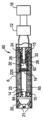
図1は、例示的な実施形態による、eベイピング装置または「紙巻たばこ様(cigalike)」装置60の側面図である。図1では、eベイピング装置60は、ねじ接合部74で、または滑り嵌め、スナップ嵌め、戻り止め、クランプ、留め金またはこれに類するもののうちの少なくとも一つなどの他の接続構造によって相互に結合された、第一のセクションまたはカートリッジ70および第二のセクション72を含む。少なくとも一つの例示的な実施形態では、第一のセクションまたはカートリッジ70は、交換可能なカートリッジでもよく、また第二のセクション72は再使用可能なセクションでもよい。別の方法として、第一のセクションまたはカートリッジ70および第二のセクション72は、一つの部品として一体的に形成されてもよい。少なくとも一つの実施形態では、第二のセクション72は、その遠位端28にLEDを含む。
FIG. 1 is a side view of an e-vaping device or "cigalike"
図2は、eベイピング装置の例示的な実施形態の断面図である。図2に示すように、第一のセクションまたはカートリッジ70は、口側端挿入部20、毛細管18、および貯蔵部14を収容することができる。
FIG. 2 is a cross-sectional view of an exemplary embodiment of an e-vaping device. As shown in FIG. 2, the first section or
例示的な実施形態では、貯蔵部14は、内管(図示せず)の周りに巻き付けたガーゼを含んでもよい。例えば、貯蔵部14は、内側に巻き付けたガーゼを囲む外側に巻き付けたガーゼで形成されるか、またはこれを含んでもよい。少なくとも一つの例示的な実施形態では、貯蔵部14は、アルミナセラミックで形成されるか、またはばらの粒子、ばらの繊維、または織布もしくは不織布繊維の形態で、これを含んでもよい。別の方法として、貯蔵部14は、コットンもしくはガーゼなどのセルロース系材料、またはばらの繊維を束ねた形態のポリエチレンテレフタラートなどのポリマー材料で形成されるか、またはこれらを含んでもよい。貯蔵部14についてのより詳細な説明を以下に提供する。
In an exemplary embodiment,
第二のセクション72は、電源12と、電源12を制御するように構成された制御回路11と、吸煙センサー16とを収容することができる。吸煙センサー16は、成人eベイピング装置使用者がeベイピング装置60で吸引する時に感知するように構成されており、これによって制御回路11を介して電源12の動作を引き起こして、貯蔵部14内に収容されたプレベイパー製剤を加熱して、これによりベイパーを形成する。第二のセクション72のねじ付き部分74は、第一のセクションまたはカートリッジ70に接続されていない時に、電池充電器に接続して電池または電源セクション12を充電することができる。
The
例示的な実施形態では、毛細管18は、導電性材料から形成され、または導電性材料を含み、従って管18を通して電流を流すことによって独自のヒーターとなるように構成され得る。毛細管18は、毛細管18が経験する動作温度において必要な構造的完全性を維持しながらも、加熱、例えば抵抗加熱が可能であり、プレベイパー製剤とは反応しない任意の導電性材料であってもよい。毛細管18を形成するために適切な材料は、ステンレス鋼、銅、銅合金、フィルム抵抗性材料で覆われた多孔性のセラミック材料、ニッケル・クロム合金、およびその組み合わせのうちの一つ以上である。例えば、毛細管18はステンレス鋼毛細管18であり、毛細管18の長さに沿った直流電流または交流電流の通過のためにそれらに取り付けられる電気リード26を介してヒーターとして機能する。従って、ステンレス鋼毛細管18は、例えば抵抗加熱によって加熱される。別の方法として、毛細管18は、例えばガラス管などの非金属管でもよい。こうした実施形態では、毛細管18はまた、例えばガラス管に沿って配置されるステンレス鋼、ニクロームまたはプラチナワイヤなどの導電材料も含み、例えば抵抗的に加熱することができる。ガラス管に沿って配置される導電材料が加熱されると、毛細管18内に存在するプレベイパー製剤は、毛細管18内のプレベイパー製剤を少なくとも部分的に揮発させるのに十分な温度まで加熱される。
In an exemplary embodiment,
少なくとも一つの実施形態では、電気リード26が毛細管18の金属部分に結合される。少なくとも一つの実施形態において、1本の電気リード26が毛細管18の第一の上流部分101に結合され、第二の電気リード26が毛細管18の下流の端部102に結合される。
In at least one embodiment,
動作時、成人eベイピング装置使用者が、eベイピング装置を吸引する時、吸煙センサー16は、成人eベイピング装置使用者の吸引により生じた圧力勾配を検出し、制御回路11は、毛細管18に電力を供給することによって、貯蔵部14内に位置するプレベイパー製剤の加熱を制御する。毛細管18が加熱されると、毛細管18の加熱部分内に含まれるプレベイパー製剤が揮発されて出口63から放出され、ここでプレベイパー製剤が拡張し、空気と混合されて、混合チャンバー240内でベイパーを形成する。
In operation, when an adult e-vaping device user inhales from the e-vaping device, the
図2に示す通り、貯蔵部14は、貯蔵部14内にプレベイパー製剤を維持し、貯蔵部14が圧迫されて、そこに圧力が適用されると開くように構成された弁40を含み、成人eベイピング装置使用者が口側端挿入部20でeベイピング装置を吸引するとき、圧力が生成され、その結果、貯蔵部14が、貯蔵部14の出口62を通してプレベイパー製剤を毛細管18に押し出すことになる。少なくとも一つの実施形態では、臨界の最小圧力に達した時に弁40が開き、プレベイパー製剤が貯蔵部14から不注意に分与されることが回避される。少なくとも一つの実施形態では、圧力スイッチ44を押すのに必要な圧力は十分に高いので、圧力スイッチ44が物理的動作または外側の物体の衝突などの外的要因により不注意に押されることによる偶発的な加熱が回避される。
As shown in FIG. 2, the
例示的な実施形態の電源12は、eベイピング装置60の第二のセクション72内に配置された電池を含むことができる。電源12は、電圧をかけるように構成され、貯蔵部14内に収容されたプレベイパー製剤を揮発させる。
The
少なくとも一つの実施形態では、毛細管18と電気リード26との間の電気接点は実質的に導電性、かつ温度抵抗性であり、一方で毛細管18は実質的に抵抗性があるので、発熱は接点ではなく主に毛細管18に沿って生じる。
In at least one embodiment, the electrical contact between the
電源セクションまたは電池12は再充電可能であってもよく、外部充電装置による電池の充電を可能にする回路を含んでもよい。例示的な実施形態では、回路は充電されたとき、電子ベイピング装置の出口を介して所与の回数の吸引に対して電力を提供し、その後、回路は外部充電装置に再接続しなければならない可能性がある。
The power supply section or
少なくとも一つの実施形態では、eベイピング装置60は、例えばプリント基板上に搭載することができる制御回路11を含んでもよい。制御回路11は、装置が起動された時に発光するように構成されたヒーター作動灯27も含んでもよい。少なくとも一つの実施形態では、ヒーター作動灯27は、少なくとも一つのLEDを含み、eベイピング装置60の遠位端28にあって、ヒーター作動灯27が、電子ベイピング装置の出口を介して吸引中に、燃焼する石炭の外観をしたキャップを照らすようにする。さらに、ヒーター作動灯27は、成人eベイピング装置使用者から見えるように構成され得る。灯27はまた、所望に応じて、成人eベイピング装置使用者が灯27を有効化する、無効化する、または有効化と無効化の両方を行うことができるように構成することもでき、それによって灯27は所望に応じてベイピング中に有効化しない。
In at least one embodiment,
少なくとも一つの実施形態では、eベイピング装置60は、少なくとも二つの軸から離れた分岐出口21を有する口側端挿入部20をさらに含み、分岐出口21は口側端挿入部20の周りに一様に分布され、eベイピング装置の動作中、成人eベイピング装置使用者の口内にベイパーを実質的に一様に分布するようにする。少なくとも一つの実施形態では、口側端挿入部20は、少なくとも二つの分岐出口21(例えば、3~8個以上の出口)を含む。少なくとも一つの実施形態では、口側端挿入部20の出口21は、軸から離れた通路23の端部に位置し、eベイピング装置60の長手方向に対して外向きの角度を有する(例えば、分岐状)。本明細書で使用される「軸から離れた」という用語は、eベイピング装置の長手方向に対してある角度を有することを意味する。
In at least one embodiment, the
少なくとも一つの実施形態では、eベイピング装置60は、たばこ由来の製品とほぼ同じサイズである。一部の実施形態では、eベイピング装置60は、約80ミリメートル~約110ミリメートルの長さ、例えば、約80ミリメートル~約100ミリメートルの長さおよび約7ミリメートル~約10ミリメートルの直径としうる。
In at least one embodiment,
eベイピング装置60の外側円筒形ハウジング22は、適切な任意の材料または材料の組み合わせから形成されるか、これを含んでもよい。少なくとも一つの実施形態において、外側円筒形ハウジング22は、少なくとも部分的に金属で形成され、制御回路11と、電源12と、吸煙センサー16とを接続する電気回路の一部である。
The outer
図2に示すように、eベイピング装置60は、プレベイパー製剤貯蔵部14および毛細管18を収容することができる中間セクション(第三のセクション)73も含んでもよい。中間セクション73は、第一のセクションまたはカートリッジ70の上流端でねじ接合部74’に嵌合されるように、および第二のセクション72の下流端でねじ接合部74に嵌合されるように構成することができる。この例示的な実施形態では、第一のセクションまたはカートリッジ70は口側端挿入部20を収容し、一方で第二のセクション72は電源12と、電源12を制御するように構成された制御回路11とを収容する。
As shown in FIG. 2, the
図3は、例示的な実施形態によるeベイピング装置の断面図である。少なくとも一つの実施形態では、毛細管18をクリーニングする必要性を回避するように、第一のセクションまたはカートリッジ70は交換可能である。少なくとも一つの実施形態では、第一のセクションまたはカートリッジ70と、第二のセクション72を、ねじ接続なしで一体として形成して、使い捨て可能なeベイピング装置を形成してもよい。
FIG. 3 is a cross-sectional view of an e-vaping device according to an example embodiment. In at least one embodiment, the first section or
図3に示すように、他の例示的な実施形態では、弁40は二方弁とすることができ、貯蔵部14は加圧することができる。例えば、貯蔵部14は、貯蔵部14に一定の圧力を印加するように構成された加圧機構405を用いて加圧することができる。そのため、貯蔵部14内に収容されているプレベイパー製剤の加熱によって形成されたベイパーの排出が促進される。貯蔵部14に対する圧力が軽減されると弁40は閉じ、加熱された毛細管18は、弁40の下流に残留しているプレベイパー製剤があれば放出する。
As shown in FIG. 3, in other exemplary embodiments,
図4は、eベイピング装置の別の例示的な実施形態の長手方向の断面図である。図4では、eベイピング装置60は、上流シール15内の中央空気通路24を含むことができる。中央空気通路24は、内管65に対して開く。さらに、eベイピング装置60は、プレベイパー製剤を貯蔵するよう構成された貯蔵部14を含む。貯蔵部14は、プレベイパー製剤および随意にその中にプレベイパー製剤を貯蔵するように構成される、ガーゼなどの貯蔵媒体25を含む。ある実施形態では、貯蔵部14は、外側管6と内管65との間の外側環状部の中に収容される。環状部は、プレベイパー製剤の貯蔵部14からの漏れを防止するために、シール15によって上流端部で、およびストッパー10によって下流端部でシールされる。ヒーターが起動される時、芯220の中央部分内に存在するプレベイパー製剤が気化されてベイパーを形成するように、ヒーター19は芯220の中央部分を少なくとも部分的に囲む。ヒーター19は、2本の間隙を介した電気リード26によって電池12へと接続される。eベイピング装置60は、少なくとも二つの出口21を有する口側端挿入部20をさらに含む。口側端挿入部20は、内管65の内部、およびストッパー10を通して延びる中央通路64を介して中央空気通路24と流体連通する。
FIG. 4 is a longitudinal cross-sectional view of another exemplary embodiment of an e-vaping device. In FIG. 4,
eベイピング装置60は、シール15内の中央空気通路24の下流端82において不浸透性プラグ30を含む、気流ダイバーターを含んでもよい。少なくとも一つの例示的な実施形態では、中央空気通路24は、シール15内の中央通路に軸方向に延在し、シール15は、外側管6と内管65との間の環状部の上流端を密封する。半径方向空気チャネル32は、中央通路20から内管65に向かって外側に空気を方向づける。動作時、成人eベイピング装置使用者が、電子ベイピング装置の出口を介してを吸引する時、吸煙センサー16は、電子ベイピング装置の出口を介して成人eベイピング装置使用者の吸引により生じた圧力勾配を検出し、その結果、制御回路11は、ヒーター19に電力を供給することによって、貯蔵部14内に位置するプレベイパー製剤の加熱を制御する。
The
図5Aは、繊維基質を含まない貯蔵部の斜視図である。図5Aでは、eベイピング装置の典型的な貯蔵部14は、プレベイパー製剤溶液を貯蔵するように構成されたガーゼまたは他の繊維材料110を含み、プレベイパー製剤溶液は、芯220に伝送され、eベイピング装置の動作中、ヒーター19によって加熱される。典型的には、ガーゼまたは繊維材料110は、巻き付けた形態であってもよく、高密度ガーゼである内側ガーゼ、および拡散ガーゼである外側ガーゼを含んでもよい。内側ガーゼおよび外側ガーゼ110は、プレベイパー製剤を貯蔵するように構成されている。
FIG. 5A is a perspective view of a reservoir without a fibrous matrix. In FIG. 5A, a
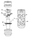
図5Bは、少なくとも一つの例示的な実施形態による、繊維基質を含む貯蔵部の斜視図である。図5Bでは、eベイピング装置の貯蔵部14は、プレベイパー製剤溶液(図示せず)を貯蔵するように構成されたガーゼまたは他の繊維材料210を含み、プレベイパー製剤溶液は、芯220に移され、eベイピング装置の動作中、ヒーター19によって加熱される。典型的に、ガーゼまたは繊維材料210は、巻き付けた形態であってもよく、例えば高密度ガーゼを含んでもよい。ガーゼ210は、プレベイパー製剤を含んでもよい。例示的な実施形態では、ガーゼ210は、複数の繊維230の長さに基づいて、実質的に互いに絡み合わないように構成された不溶性ポリマー繊維であってもよい、複数の繊維230の基質を含む。従って、複数の繊維230のそれぞれの長さは、繊維230の間の絡み合いが実質的に防止されるようなものである。例えば、複数の繊維230の長さは、約3ミリメートル~約7ミリメートルの範囲内であり得る。複数の繊維230の長さはまた、約5ミリメートルであってもよい。例示的な実施形態では、繊維230のそれぞれの長さが約3ミリメートルより短い場合、繊維230は、eベイピング装置(図示せず)の電池に最も近い貯蔵部14の側面などの、貯蔵部14の一つ以上の固定された位置で密集し得、従って十分にプレベイパー製剤を保持せず、結果的に漏れを介してプレベイパー製剤の損失の可能性につながる。繊維230のそれぞれの長さが、約7ミリメートルより長い場合、繊維230は他の繊維230と絡み合う可能性があり、結果的に可動が少なくなり得、eベイピング装置の動作中に、プレベイパー製剤は貯蔵部14の外側部分から貯蔵部14の内側部分および芯220へ流れるのを妨げられ、ヒーター19によって加熱される。
FIG. 5B is a perspective view of a reservoir including a fibrous matrix, according to at least one exemplary embodiment. In FIG. 5B, the
例示的な実施形態では、約30パーセントの複数の繊維230が、約3ミリメートルの長さを有し、約50パーセントの複数の繊維230が、約5ミリメートルの長さを有し、約20パーセントの複数の繊維230が、約7ミリメートルの長さを有する。他の例示的な実施形態では、約20パーセントの複数の繊維230が、約3ミリメートルの長さを有し、約75パーセントの複数の繊維230が、約5ミリメートルの長さを有し、約5パーセントの複数の繊維230が、約7ミリメートルの長さを有する。他の例示的な実施形態では、約30パーセントの複数の繊維230が、約3ミリメートルの長さを有し、約60パーセントの複数の繊維230が、約5ミリメートルの長さを有し、約10パーセントの複数の繊維230が、約7ミリメートルの長さを有する。
In an exemplary embodiment, about 30 percent of the plurality of
例示的な実施形態では、複数の繊維230の直径は、約20マイクロメートル~約28マイクロメートルの範囲内である。例示的な実施形態では、繊維230のそれぞれの直径が上記の範囲外にある場合、つまり約20マイクロメートルより小さいかまたは約28マイクロメートルより大きい場合、繊維230はプレベイパー製剤を十分に保持するのを阻止されるか、または他の繊維230と絡み合うために可動が少なくなるかのどちらかになり得る。その結果、繊維230は可動が少なくなり、プレベイパー製剤の流れは、eベイピング装置の動作中に、ヒーター19によって加熱されるようにするために、プレベイパー製剤が貯蔵部14の外側部分から貯蔵部14の内側部分および芯220へ流れるのを妨げられる。例えば、複数の繊維230の直径は、約24マイクロメートルである。
In an exemplary embodiment, the diameter of the plurality of
例示的な実施形態では、複数の繊維230の表面積は、約13平方インチ~約17平方インチの範囲内である。例示的な実施形態では、繊維230のそれぞれの表面積が、上記の範囲外にある場合、つまり約13平方インチより小さく、または約17平方インチより大きい場合、繊維230は可動が小さくなり得、他の繊維230と絡み合う可能性があり、結果的に繊維230の可動が少なくなり、従って貯蔵部14の外側部分から貯蔵部14の内側部分および芯220へのプレベイパー製剤の流れを妨げ、eベイピング装置の動作中に、ヒーター19によって加熱される。例えば、複数の繊維230のそれぞれの表面積は、約15平方インチである。
In an exemplary embodiment, the surface area of the plurality of
図6Aおよび6Bは、少なくとも一つの例示的な実施形態による、プレベイパー製剤溶液内に複数の繊維を含む貯蔵部の断面である。図6Aおよび6Bでは、eベイピング装置の動作中、eベイピング装置の貯蔵部14の半径方向の断面図である。図6Aでは、貯蔵部14が実質的にプレベイパー製剤溶液で満杯の状態を図示し、複数の繊維230は、プレベイパー製剤溶液を貯蔵するよう構成されたガーゼまたは他の繊維材料210内の貯蔵部14内に、実質的に均一に分布される。プレベイパー製剤溶液が貯蔵部14に含まれるとき、実質的にすべてのプレベイパー製剤溶液が複数の繊維230に吸収されるかまたは浸され、結果的に貯蔵部14内のプレベイパー製剤溶液の懸濁液となる。例示的な実施形態では、プレベイパー製剤溶液は、繊維230間のすきま空間内に閉じ込められる。その結果、プレベイパー製剤溶液は、実質的に貯蔵部14内に保持され、プレベイパー製剤溶液の流れは、実質的に貯蔵部14から意図せずに流れ出るのを防止する。従って、プレベイパー製剤溶液の浪費は、低減されるか、または実質的に防止される。
6A and 6B are cross-sections of a reservoir containing a plurality of fibers within a pre-vapor formulation solution, according to at least one exemplary embodiment. 6A and 6B are radial cross-sectional views of the
図6Bは、プレベイパー製剤溶液が大部分使用され、貯蔵部14が実質的に空である状態を図示する。その結果、複数の繊維230および高密度ガーゼ210は圧縮され、結果として複数の繊維230により事前に浸され、または吸収されたプレベイパー製剤溶液の追加量を表現する。複数の繊維230と高密度ガーゼ210との圧縮は、しぼる動作に類似しており、複数の繊維230によって事前に浸された、または吸収されたプレベイパー製剤溶液の残りの量は、繊維230から吐き出され、芯(図示せず)に移され、ヒーター(図示せず)によって加熱されて、eベイピング装置から吸引される。その結果、貯蔵部14に繊維を含まないeベイピング装置よりも、eベイピング装置の動作中、多くのプレベイパー製剤溶液が使用され、プレベイパー製剤溶液の浪費は低減されるか、または実質的に防止される。
Figure 6B illustrates a situation where the pre-vapor formulation solution is mostly used and the
様々な例示的な実施形態では、複数の繊維230およびガーゼ210は、図6Bに図示するように、貯蔵部14にわたって一つ以上の位置で、貯蔵部14の中心の周りに放射状に濃縮し、または融合し得る。しぼる動作は、融合場所のそれぞれで起こり得、結果的に残りのプレベイパー製剤溶液を複数の繊維230から吐き出すようにする。
In various exemplary embodiments, the plurality of
図7Aおよび7Bは、複数の繊維を含まないeベイピング装置の貯蔵部の断面である。図7Aおよび7Bでは、eベイピング装置の動作中、eベイピング装置の貯蔵部14’の半径方向の断面図である。図7Aでは、貯蔵部14’が、プレベイパー製剤溶液140で実質的に満杯になっており、プレベイパー製剤溶液140は、ガーゼまたは他の繊維材料110内に実質的に均一に分布される。図7Bは、プレベイパー製剤溶液140が大部分使用され、貯蔵部14’が実質的に空である状態を図示する。その結果、プレベイパー製剤溶液140は、ガーゼ110内の一つ以上の場所で、融合する。しかし、貯蔵部14’内の繊維の存在により形成されたしぼる効果の不在で、プレベイパー製剤溶液140の残量は、ガーゼ110から吐き出されず、芯(図示せず)へ移されて、ヒーター(図示せず)により加熱され、eベイピング装置から吸引される。
7A and 7B are cross-sections of a reservoir of an e-vaping device that does not include multiple fibers. 7A and 7B are radial cross-sectional views of the reservoir 14' of the e-vaping device during operation of the e-vaping device. In FIG. 7A, reservoir 14' is substantially full of
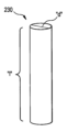
図8は、少なくとも一つの例示的な実施形態による、ポリマー繊維を図示したものである。図8では、ポリマー繊維230は、直径「d」および長さ「l」を有する、略長手形状を有してもよい。様々な例示的な実施形態では、ポリマー繊維230の直径「d」は、約20マイクロメートル~約28マイクロメートルの範囲内であり得る。さらに、様々な例示的な実施形態では、ポリマー繊維230の長さ「l」は、約3ミリメートル~約7ミリメートルの範囲内であり得る。繊維の表面積、つまり繊維の外部表面は、約13平方インチ~約17平方インチの範囲内であり得る。
FIG. 8 is a diagram of a polymer fiber according to at least one exemplary embodiment. In FIG. 8,
従って、例示的な実施形態を説明しており、これらは多くの方法で変形され得ることが明らかであろう。こうした変形は、例示的な実施形態の意図される範囲を逸脱するものと見なされず、当業者にとって明らかであろうすべての変更は、以下の請求項の範囲内に含まれることが意図される。 Thus, while exemplary embodiments have been described, it will be obvious that the same may be varied in many ways. Such variations are not considered a departure from the intended scope of the exemplary embodiments, and all modifications that would be apparent to those skilled in the art are intended to be included within the scope of the following claims.
Claims (9)
前記プレベイパー製剤を貯蔵するように構成された貯蔵部を備え、
前記貯蔵部が、前記プレベイパー製剤の懸濁液中に複数のポリマー繊維を含有し、
前記貯蔵部がガーゼを含み、前記ガーゼが前記複数の繊維を含み、
前記複数の繊維のそれぞれの長さが、3ミリメートル~7ミリメートルの範囲内であり、前記複数の繊維のそれぞれの直径が、20マイクロメートル~28マイクロメートルの範囲内にあり、
前記複数の繊維が、前記複数の繊維の前記それぞれの長さおよび前記それぞれの直径に基づいて、可動性および実質的に互いに絡み合わないうちの少なくとも一つであるように構成される、カートリッジ。 A cartridge configured to contain a pre-vapor formulation for an e-vaping device, the cartridge comprising:
comprising a reservoir configured to store the pre-vapor formulation;
the reservoir contains a plurality of polymer fibers in suspension of the prevapor formulation;
the reservoir includes gauze, the gauze includes the plurality of fibers,
The length of each of the plurality of fibers is within the range of 3 mm to 7 mm, and the diameter of each of the plurality of fibers is within the range of 20 micrometers to 28 micrometers,
The cartridge is configured such that the plurality of fibers are at least one of mobile and substantially non-intertwined based on the respective lengths and the respective diameters of the plurality of fibers.
Applications Claiming Priority (4)
| Application Number | Priority Date | Filing Date | Title |
|---|---|---|---|
| US15/226,420 US11357937B2 (en) | 2016-08-02 | 2016-08-02 | Collapsible fiber matrix reservoir for an e-vaping device |
| US15/226,420 | 2016-08-02 | ||
| JP2019503665A JP2019531702A (en) | 2016-08-02 | 2017-08-02 | eFoldable fiber substrate storage for vapouring equipment |
| PCT/EP2017/069564 WO2018024785A1 (en) | 2016-08-02 | 2017-08-02 | Collapsible fiber matrix reservoir for an e-vaping device |
Related Parent Applications (1)
| Application Number | Title | Priority Date | Filing Date |
|---|---|---|---|
| JP2019503665A Division JP2019531702A (en) | 2016-08-02 | 2017-08-02 | eFoldable fiber substrate storage for vapouring equipment |
Publications (2)
| Publication Number | Publication Date |
|---|---|
| JP2022145950A JP2022145950A (en) | 2022-10-04 |
| JP7367146B2 true JP7367146B2 (en) | 2023-10-23 |
Family
ID=59506297
Family Applications (2)
| Application Number | Title | Priority Date | Filing Date |
|---|---|---|---|
| JP2019503665A Pending JP2019531702A (en) | 2016-08-02 | 2017-08-02 | eFoldable fiber substrate storage for vapouring equipment |
| JP2022128792A Active JP7367146B2 (en) | 2016-08-02 | 2022-08-12 | Collapsible fiber matrix storage for e-vaping devices |
Family Applications Before (1)
| Application Number | Title | Priority Date | Filing Date |
|---|---|---|---|
| JP2019503665A Pending JP2019531702A (en) | 2016-08-02 | 2017-08-02 | eFoldable fiber substrate storage for vapouring equipment |
Country Status (10)
| Country | Link |
|---|---|
| US (2) | US11357937B2 (en) |
| EP (1) | EP3493689B1 (en) |
| JP (2) | JP2019531702A (en) |
| KR (1) | KR102555039B1 (en) |
| CN (1) | CN109475188B (en) |
| CA (1) | CA3027000A1 (en) |
| IL (1) | IL263443A (en) |
| MX (1) | MX2019001206A (en) |
| RU (1) | RU2740724C2 (en) |
| WO (1) | WO2018024785A1 (en) |
Families Citing this family (3)
| Publication number | Priority date | Publication date | Assignee | Title |
|---|---|---|---|---|
| CN206062123U (en) * | 2016-10-10 | 2017-04-05 | 韩力 | A kind of gas heating type smoking product |
| GB201815469D0 (en) * | 2018-09-24 | 2018-11-07 | Nerudia Ltd | Aerosol delivery device |
| WO2020124061A1 (en) * | 2018-12-14 | 2020-06-18 | Bello Vaporizer | Automatic vapor dispensing devices and methods |
Citations (1)
| Publication number | Priority date | Publication date | Assignee | Title |
|---|---|---|---|---|
| WO2016054476A1 (en) | 2014-10-03 | 2016-04-07 | Altria Client Services Llc | Electronic vaping device and components thereof |
Family Cites Families (64)
| Publication number | Priority date | Publication date | Assignee | Title |
|---|---|---|---|---|
| DE1065364B (en) * | 1954-06-16 | 1959-09-17 | John Joseph Smith, Highland Park N. J. (V. St. A.) | Non-woven fiber |
| US2965102A (en) * | 1956-04-27 | 1960-12-20 | Kimberly Clark Co | Sanitary napkin |
| US3067747A (en) * | 1959-09-04 | 1962-12-11 | Kimberly Clark Co | Cellulosic product |
| BR6456568D0 (en) * | 1963-02-23 | 1973-12-27 | Honshu Paper Co Ltd | PROCESS FOR THE MANUFACTURE OF PERFECTED FLUID ABSORBING MATERIAL AS WELL AS THE RESPECTIVE ABSORBENT MATERIAL |
| US3340874A (en) * | 1964-09-08 | 1967-09-12 | Johnson & Johnson | Tampon having concentric layers with different properties |
| US3430630A (en) * | 1966-04-27 | 1969-03-04 | Procter & Gamble | Sanitary napkin |
| US3663348A (en) * | 1968-05-16 | 1972-05-16 | Johnson & Johnson | A lofty and soft nonwoven, through bonded fabric |
| US3628534A (en) * | 1969-02-10 | 1971-12-21 | Tampax Inc | Catamenial tampon and method |
| US3575173A (en) * | 1969-03-13 | 1971-04-20 | Personal Products Co | Flushable disposable absorbent products |
| US3804092A (en) * | 1973-01-15 | 1974-04-16 | Johnson & Johnson | Water dispersible nonwoven fabric |
| US4002171A (en) * | 1975-03-17 | 1977-01-11 | Personal Products Company | Water-dispersible ionic polyurethane binder for nonwoven fabrics |
| US3971379A (en) * | 1975-04-04 | 1976-07-27 | Personal Products Company | Absorbent hydrophilic cellulosic product |
| US4813437A (en) * | 1984-01-09 | 1989-03-21 | Ray J Philip | Nicotine dispensing device and method for the manufacture thereof |
| US4872870A (en) * | 1984-08-16 | 1989-10-10 | Chicopee | Fused laminated fabric and panty liner including same |
| US4800903A (en) * | 1985-05-24 | 1989-01-31 | Ray Jon P | Nicotine dispenser with polymeric reservoir of nicotine |
| US4793366A (en) * | 1985-11-12 | 1988-12-27 | Hill Ira D | Nicotine dispensing device and methods of making the same |
| US4922901A (en) * | 1988-09-08 | 1990-05-08 | R. J. Reynolds Tobacco Company | Drug delivery articles utilizing electrical energy |
| US4947875A (en) * | 1988-09-08 | 1990-08-14 | R. J. Reynolds Tobacco Company | Flavor delivery articles utilizing electrical energy |
| US4947874A (en) * | 1988-09-08 | 1990-08-14 | R. J. Reynolds Tobacco Company | Smoking articles utilizing electrical energy |
| US5868724A (en) * | 1993-10-22 | 1999-02-09 | The Procter & Gamble Company | Non-continuous absorbent cores comprising a porous macrostructure of absorbent gelling particles |
| US5509430A (en) * | 1993-12-14 | 1996-04-23 | American Filtrona Corporation | Bicomponent fibers and tobacco smoke filters formed therefrom |
| US7709694B2 (en) * | 1998-12-08 | 2010-05-04 | Quick-Med Technologies, Inc. | Materials with covalently-bonded, nonleachable, polymeric antimicrobial surfaces |
| US20050033251A1 (en) * | 1998-12-08 | 2005-02-10 | Quick-Med Technologies, Inc. | Controlled release of biologically active substances from select substrates |
| US6041789A (en) * | 1999-01-28 | 2000-03-28 | K&B Technologies, L.L.C. | Cigarette substitute device and composition for use therein |
| US6723428B1 (en) * | 1999-05-27 | 2004-04-20 | Foss Manufacturing Co., Inc. | Anti-microbial fiber and fibrous products |
| US6835678B2 (en) * | 2000-05-04 | 2004-12-28 | Kimberly-Clark Worldwide, Inc. | Ion sensitive, water-dispersible fabrics, a method of making same and items using same |
| US7687681B2 (en) * | 2000-05-26 | 2010-03-30 | Kimberly-Clark Worldwide, Inc. | Menses specific absorbent systems |
| JP4073613B2 (en) * | 2000-09-01 | 2008-04-09 | ユニ・チャーム株式会社 | Absorbent article using back sheet having continuous filament |
| WO2002038846A2 (en) | 2000-11-10 | 2002-05-16 | Kimberly-Clark Worldwide, Inc. | Hydroentangled nonwoven composite structures containing recycled synthetic fibrous materials |
| JP3922877B2 (en) * | 2000-11-27 | 2007-05-30 | ユニ・チャーム株式会社 | Absorbent articles |
| US8840989B2 (en) * | 2001-10-29 | 2014-09-23 | Nedeljko Gvozdic | Reinforced, laminated, impregnated, and composite-like materials as cross-linked polyvinyl alcohol hydrogel structures |
| EP1572050B1 (en) * | 2002-12-20 | 2021-04-21 | The Procter & Gamble Company | Tufted fibrous web |
| CA2507179C (en) * | 2002-12-20 | 2008-06-17 | The Procter & Gamble Company | Tufted laminate web |
| US20040123555A1 (en) * | 2002-12-26 | 2004-07-01 | Cole Jefferson Anthony | Pre manufactured structural panel consisting of a flame retardant external crust and an aeroboard core fabricated from laminations of uncompressed cardboard, impregnated by resin solutions recovered from post consumer thermoplastics |
| US20040182403A1 (en) * | 2003-02-28 | 2004-09-23 | Sven-Borje Andersson | Container comprising nicotine and the use and manufacture thereof |
| US20050177122A1 (en) * | 2004-02-09 | 2005-08-11 | Berba Maria L.M. | Fluid management article and methods of use thereof |
| CN2719043Y (en) * | 2004-04-14 | 2005-08-24 | 韩力 | Atomized electronic cigarette |
| US7521493B2 (en) * | 2005-01-10 | 2009-04-21 | E. I. Du Pont De Nemours And Company | Slurries containing microfiber and micropowder, and methods for using and making same |
| EP2537498B1 (en) | 2005-03-23 | 2013-12-18 | Kao Corporation | Absorbent article |
| US20080167634A1 (en) * | 2005-03-23 | 2008-07-10 | Takuya Kouta | Absorbent Article |
| CN201067079Y (en) * | 2006-05-16 | 2008-06-04 | 韩力 | Simulation aerosol inhaler |
| US7726320B2 (en) * | 2006-10-18 | 2010-06-01 | R. J. Reynolds Tobacco Company | Tobacco-containing smoking article |
| US8613284B2 (en) * | 2008-05-21 | 2013-12-24 | R.J. Reynolds Tobacco Company | Cigarette filter comprising a degradable fiber |
| CN201379072Y (en) | 2009-02-11 | 2010-01-13 | 韩力 | Improved atomizing electronic cigarette |
| US20100310845A1 (en) * | 2009-06-03 | 2010-12-09 | Eric Bryan Bond | Fluid permeable structured fibrous web |
| EP2338361A1 (en) | 2009-12-23 | 2011-06-29 | Philip Morris Products S.A. | An elongate heater for an electrically heated aerosol-generating system |
| ES2741139T5 (en) | 2010-03-26 | 2022-11-14 | Japan Tobacco Inc | smoking article |
| FR2960240B1 (en) * | 2010-05-21 | 2012-08-03 | Arkema France | REFRESHING TEXTILE BASED ON PEBA HYDROPHOBE |
| KR101057774B1 (en) | 2010-12-13 | 2011-08-19 | 신종수 | Electronic cigarette |
| KR101324667B1 (en) | 2011-05-27 | 2013-11-04 | 퓨처사이버 주식회사 | Charging type electronic suction device in a body |
| RU110608U1 (en) | 2011-08-12 | 2011-11-27 | Сергей Павлович Кузьмин | ELECTRONIC CIGARETTE |
| US20130123409A1 (en) * | 2011-11-11 | 2013-05-16 | Eastman Chemical Company | Solvent-borne products containing short-cut microfibers |
| HUE030730T2 (en) | 2011-12-30 | 2017-05-29 | Philip Morris Products Sa | Aerosol generating device with air flow detection |
| US9282772B2 (en) * | 2012-01-31 | 2016-03-15 | Altria Client Services Llc | Electronic vaping device |
| PL2838385T3 (en) * | 2012-04-18 | 2020-06-01 | Fontem Holdings 1 B.V. | Electronic cigarette |
| UA118101C2 (en) * | 2013-02-22 | 2018-11-26 | Олтріа Клайєнт Сервісиз Ллк | Electronic smoking article |
| US20140261486A1 (en) * | 2013-03-12 | 2014-09-18 | R.J. Reynolds Tobacco Company | Electronic smoking article having a vapor-enhancing apparatus and associated method |
| US20140261487A1 (en) * | 2013-03-14 | 2014-09-18 | R. J. Reynolds Tobacco Company | Electronic smoking article with improved storage and transport of aerosol precursor compositions |
| DE102013010724A1 (en) | 2013-06-27 | 2014-12-31 | Mann+Hummel Gmbh | A whole blood plastic hollow fiber membrane filter medium and use thereof for separating blood plasma / serum from whole blood |
| US9974334B2 (en) * | 2014-01-17 | 2018-05-22 | Rai Strategic Holdings, Inc. | Electronic smoking article with improved storage of aerosol precursor compositions |
| UA120431C2 (en) * | 2014-02-28 | 2019-12-10 | Олтріа Клайєнт Сервісиз Ллк | Electronic vaping device and components thereof |
| KR20170035962A (en) * | 2014-07-24 | 2017-03-31 | 알트리아 클라이언트 서비시즈 엘엘씨 | Electronic vaping device and components thereof |
| WO2016069903A1 (en) * | 2014-10-29 | 2016-05-06 | Altria Client Services Llc | E-vaping cartridge |
| CN204540821U (en) | 2015-02-12 | 2015-08-12 | 深圳市卓力能电子有限公司 | A kind of oil-cup type atomizer |
-
2016
- 2016-08-02 US US15/226,420 patent/US11357937B2/en active Active
-
2017
- 2017-08-02 RU RU2019103838A patent/RU2740724C2/en active
- 2017-08-02 WO PCT/EP2017/069564 patent/WO2018024785A1/en active Search and Examination
- 2017-08-02 CA CA3027000A patent/CA3027000A1/en not_active Abandoned
- 2017-08-02 MX MX2019001206A patent/MX2019001206A/en unknown
- 2017-08-02 EP EP17746500.2A patent/EP3493689B1/en active Active
- 2017-08-02 JP JP2019503665A patent/JP2019531702A/en active Pending
- 2017-08-02 CN CN201780042656.1A patent/CN109475188B/en active Active
- 2017-08-02 KR KR1020197001062A patent/KR102555039B1/en active IP Right Grant
-
2018
- 2018-12-03 IL IL263443A patent/IL263443A/en unknown
-
2022
- 2022-05-06 US US17/738,591 patent/US20220257883A1/en active Pending
- 2022-08-12 JP JP2022128792A patent/JP7367146B2/en active Active
Patent Citations (1)
| Publication number | Priority date | Publication date | Assignee | Title |
|---|---|---|---|---|
| WO2016054476A1 (en) | 2014-10-03 | 2016-04-07 | Altria Client Services Llc | Electronic vaping device and components thereof |
Also Published As
| Publication number | Publication date |
|---|---|
| RU2740724C2 (en) | 2021-01-20 |
| RU2019103838A3 (en) | 2020-11-12 |
| US20220257883A1 (en) | 2022-08-18 |
| MX2019001206A (en) | 2019-05-02 |
| KR20190034528A (en) | 2019-04-02 |
| CN109475188A (en) | 2019-03-15 |
| US11357937B2 (en) | 2022-06-14 |
| CA3027000A1 (en) | 2018-02-08 |
| RU2019103838A (en) | 2020-09-04 |
| EP3493689A1 (en) | 2019-06-12 |
| IL263443A (en) | 2019-01-31 |
| CN109475188B (en) | 2022-11-15 |
| KR102555039B1 (en) | 2023-07-17 |
| WO2018024785A1 (en) | 2018-02-08 |
| JP2019531702A (en) | 2019-11-07 |
| EP3493689B1 (en) | 2020-06-17 |
| US20180035713A1 (en) | 2018-02-08 |
| JP2022145950A (en) | 2022-10-04 |
Similar Documents
| Publication | Publication Date | Title |
|---|---|---|
| JP7177037B2 (en) | Formulation delivery driven by the venturi effect in e-vaping devices | |
| JP7132913B2 (en) | Design and application of multi-chamber cartridges containing hydrogel formulations | |
| JP7367146B2 (en) | Collapsible fiber matrix storage for e-vaping devices | |
| CN111050577B (en) | Non-combustible tobacco vapor insert and cartridge containing non-combustible tobacco vapor insert | |
| CN108366630A (en) | Component for generating system including disabling the aerosol of component | |
| JP2018516551A (en) | Non-combustion smoking device and element thereof | |
| JP2019512256A (en) | Electronic baping apparatus and cartridge for electronic baping apparatus | |
| RU2718995C2 (en) | Non-combustible smoking device and its elements | |
| JP2019527559A (en) | Electronic vaporizer vaporizer and method of forming a vaporizer | |
| KR102661609B1 (en) | Non-combustible smoking device and its elements |
Legal Events
| Date | Code | Title | Description |
|---|---|---|---|
| A521 | Request for written amendment filed |
Free format text: JAPANESE INTERMEDIATE CODE: A523 Effective date: 20220909 |
|
| A621 | Written request for application examination |
Free format text: JAPANESE INTERMEDIATE CODE: A621 Effective date: 20220909 |
|
| A131 | Notification of reasons for refusal |
Free format text: JAPANESE INTERMEDIATE CODE: A131 Effective date: 20230529 |
|
| A521 | Request for written amendment filed |
Free format text: JAPANESE INTERMEDIATE CODE: A523 Effective date: 20230828 |
|
| TRDD | Decision of grant or rejection written | ||
| A01 | Written decision to grant a patent or to grant a registration (utility model) |
Free format text: JAPANESE INTERMEDIATE CODE: A01 Effective date: 20230911 |
|
| A61 | First payment of annual fees (during grant procedure) |
Free format text: JAPANESE INTERMEDIATE CODE: A61 Effective date: 20231011 |
|
| R150 | Certificate of patent or registration of utility model |
Ref document number: 7367146 Country of ref document: JP Free format text: JAPANESE INTERMEDIATE CODE: R150 |