JP7366879B2 - diesel engine - Google Patents
diesel engine Download PDFInfo
- Publication number
- JP7366879B2 JP7366879B2 JP2020218647A JP2020218647A JP7366879B2 JP 7366879 B2 JP7366879 B2 JP 7366879B2 JP 2020218647 A JP2020218647 A JP 2020218647A JP 2020218647 A JP2020218647 A JP 2020218647A JP 7366879 B2 JP7366879 B2 JP 7366879B2
- Authority
- JP
- Japan
- Prior art keywords
- sleeve
- diesel engine
- fuel injector
- fuel injection
- vortex chamber
- Prior art date
- Legal status (The legal status is an assumption and is not a legal conclusion. Google has not performed a legal analysis and makes no representation as to the accuracy of the status listed.)
- Active
Links
Images


Classifications
-
- Y—GENERAL TAGGING OF NEW TECHNOLOGICAL DEVELOPMENTS; GENERAL TAGGING OF CROSS-SECTIONAL TECHNOLOGIES SPANNING OVER SEVERAL SECTIONS OF THE IPC; TECHNICAL SUBJECTS COVERED BY FORMER USPC CROSS-REFERENCE ART COLLECTIONS [XRACs] AND DIGESTS
- Y02—TECHNOLOGIES OR APPLICATIONS FOR MITIGATION OR ADAPTATION AGAINST CLIMATE CHANGE
- Y02T—CLIMATE CHANGE MITIGATION TECHNOLOGIES RELATED TO TRANSPORTATION
- Y02T10/00—Road transport of goods or passengers
- Y02T10/10—Internal combustion engine [ICE] based vehicles
- Y02T10/12—Improving ICE efficiencies
Landscapes
- Combustion Methods Of Internal-Combustion Engines (AREA)
- Fuel-Injection Apparatus (AREA)
Description
本発明は、ディーゼルエンジンに関し、詳しくは、精密な燃料噴射を行うことができるディーゼルエンジンに関する。 The present invention relates to a diesel engine, and more particularly, to a diesel engine capable of precise fuel injection.
従来、ディーゼルエンジンとして、渦室式燃焼室と、渦室に向かうシリンダヘッド内の挿通孔と、挿通孔に挿通された燃料インジェクタを備えたものがある(例えば、特許文献1参照)。 Conventionally, there is a diesel engine that includes a swirl chamber type combustion chamber, an insertion hole in a cylinder head toward the swirl chamber, and a fuel injector inserted into the insertion hole (for example, see Patent Document 1).
《問題点》 精密な燃料噴射を行うことができないことがある。
特許文献1のエンジンでは、燃料インジェクタの本体部がシリンダヘッド内に配置されている場合、シリンダヘッドの熱で燃料インジェクタ本体部が過熱し、精密な燃料噴射ができないことがある。
[Problem] Precise fuel injection may not be possible.
In the engine of
本発明の課題は、精密な燃料噴射を行うことができるディーゼルエンジンを提供することにある。 An object of the present invention is to provide a diesel engine that can perform precise fuel injection.
本願発明の主要な構成は、次の通りである。
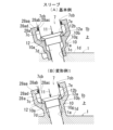
図1(A)に例示するように、シリンダ(3)と、シリンダヘッド(1)と、シリンダヘッド(1)内の渦室(2)と、シリンダ(3)内の主燃焼室(4)と、主燃焼室(4)と渦室(2)を連通させる連通口(5)と、渦室(2)に向かうシリンダヘッド(1)内の挿通孔(1a)と、挿通孔(1a)に挿通された燃料インジェクタ(7)を備えた、ディーゼルエンジンにおいて、
図1(A)に例示するように、挿通孔(1a)からシリンダヘッド(1)外に突出するスリーブ(10)と、スリーブ(10)の突出端部(10a)に設けられた受圧面(10b)を備え、
燃料インジェクタ(7)は、径大の本体部(7c)と、径小のノズル部(7d)と、本体部(7c)とノズル部(7d)の段差部分に形成された押圧面(7e)を備え、
燃料インジェクタ(7)のノズル部(7d)がスリーブ(10)内から挿通孔(1a)内に亘って挿通され、燃料インジェクタ(7)が押圧力(11)で渦室(2)側に押圧され、燃料インジェクタ(7)にかかる押圧力(11)が燃料インジェクタ(7)の押圧面(7e)から座金(12)を介してスリーブ(10)の受圧面(10b)で受け止められるように構成され、
図1(A)に例示するように、スリーブ(10)は、突出端部(10a)から突出方向に延長されたスリーブ延長カバー(28a)を備え、スリーブ延長カバー(28a)で座金(12)が外周側から覆われ、
スリーブ延長カバー(28a)の延長端部(28aa)に燃料インジェクタ(7)の本体部(7c)が内嵌され、
図1(A)等に例示するように、スリーブ延長カバー(28a)の延長端部(28aa)の内周面(28ad)と、燃料インジェクタ(7)の本体部(7c)の外周面(7cb)の間は、リングガスケット(28ac)で密封されている、ことを特徴とするディーゼルエンジン。
The main configuration of the present invention is as follows.
As illustrated in FIG. 1(A), a cylinder (3), a cylinder head (1), a vortex chamber (2) in the cylinder head (1), and a main combustion chamber (4) in the cylinder (3). , a communication port (5) that communicates the main combustion chamber (4) and the vortex chamber (2), an insertion hole (1a) in the cylinder head (1) facing the vortex chamber (2), and an insertion hole (1a). In a diesel engine equipped with a fuel injector (7) inserted into the
As illustrated in FIG. 1(A), a sleeve (10) protrudes from the insertion hole (1a) to the outside of the cylinder head (1), and a pressure receiving surface (10) provided at the protruding end (10a) of the sleeve (10). 10b),
The fuel injector (7) includes a main body part (7c) with a large diameter, a nozzle part (7d) with a small diameter, and a pressing surface (7e) formed at a step between the main body part (7c) and the nozzle part (7d). Equipped with
The nozzle part (7d) of the fuel injector (7) is inserted from the inside of the sleeve (10) into the insertion hole (1a), and the fuel injector (7) is pressed toward the vortex chamber (2) by the pressing force (11). The pressure force (11) applied to the fuel injector (7) is received from the pressure surface (7e) of the fuel injector (7) via the washer (12) by the pressure receiving surface (10b) of the sleeve (10). is,
As illustrated in FIG. 1(A), the sleeve (10) includes a sleeve extension cover (28a) extending from the protrusion end (10a) in the protrusion direction, and the sleeve extension cover (28a) connects the washer (12) with the sleeve extension cover (28a). is covered from the outer circumferential side,
The main body (7c) of the fuel injector (7) is fitted into the extension end (28aa) of the sleeve extension cover (28a),
As illustrated in FIG. 1(A) etc., the inner circumferential surface (28ad) of the extension end (28aa) of the sleeve extension cover (28a) and the outer circumferential surface (7cb) of the main body (7c) of the fuel injector (7) ) is sealed with a ring gasket (28ac).
本願発明は、次の効果を奏する。
《効果1》 精密な燃料噴射を行うことができる。
図1(A)に例示するように、このエンジンでは、スリーブ(10)により、燃料インジェクタ(7)の本体部(7c)がシリンダヘッド(1)から遠ざけられるため、シリンダヘッド(1)の熱で燃料インジェクタ(7)の本体部(7c)が過熱し難く、精密な燃料噴射を行うことができる。
《効果2》 座金(12)の外周側からスリーブ(10)内への防水や防塵を図ることができる。
図1(A)に例示するように、このエンジンでは、スリーブ延長カバー(28a)で座金(12)が外周側から覆われるため、座金(12)の外周側からスリーブ(10)内への防水や防塵を図ることができる。
《効果3》 スリーブ延長カバー(28a)の延長端部(28aa)からスリーブ延長カバー(28a)内への防水や防塵を図ることができる。
The present invention has the following effects.
<<
As illustrated in FIG. 1(A), in this engine, the main body (7c) of the fuel injector (7) is moved away from the cylinder head (1) by the sleeve (10), so the heat of the cylinder head (1) increases. The main body (7c) of the fuel injector (7) is not easily overheated, and precise fuel injection can be performed.
<<
As illustrated in FIG. 1(A), in this engine, the washer (12) is covered from the outer circumferential side with the sleeve extension cover (28a), so waterproofing from the outer circumferential side of the washer (12) into the sleeve (10) is prevented. and dustproofing.
<<
図1~12は本発明の実施形態に係るディーゼルエンジンを説明する図で、図1は実施形態のエンジンに用いるエンジン各部に関する基本例、図2~12は実施形態で用いるスリーブや封止構造等に関する基本例と変形例である。
また、図13~15は、本発明の実施形態に用いる燃料噴射孔に関する基本例や変形例に対する比較例の図である。
1 to 12 are diagrams for explaining a diesel engine according to an embodiment of the present invention. FIG. 1 is a basic example of each part of the engine used in the engine of the embodiment, and FIGS. 2 to 12 are illustrations of the sleeve, sealing structure, etc. used in the embodiment. These are basic examples and modified examples.
Further, FIGS. 13 to 15 are diagrams of comparative examples with respect to basic examples and modified examples regarding fuel injection holes used in the embodiment of the present invention.
図1に示す本発明の実施形態では、立形直列多気筒の電子燃料噴射式ディーゼルエンジンが用いられている。
図1(A)に示すように、このエンジンは、シリンダ(3)と、シリンダ(3)の上部に組み付けられたシリンダヘッド(1)と、シリンダ(3)に内嵌されたピストン(14)を備えている。
In the embodiment of the present invention shown in FIG. 1, a vertical in-line multi-cylinder electronic fuel injection diesel engine is used.
As shown in FIG. 1(A), this engine includes a cylinder (3), a cylinder head (1) assembled on the upper part of the cylinder (3), and a piston (14) fitted inside the cylinder (3). It is equipped with
図1(A)に示すように、このエンジンは、シリンダヘッド(1)内の渦室(2)と、シリンダ(3)内の主燃焼室(4)と、主燃焼室(4)と渦室(2)を連通させる連通口(5)と、渦室(2)に向かうシリンダヘッド(1)内の挿通孔(1a)と、挿通孔(1a)に挿通された燃料インジェクタ(7)を備えている。 As shown in Figure 1(A), this engine has a vortex chamber (2) in the cylinder head (1), a main combustion chamber (4) in the cylinder (3), and a vortex chamber (4) in the cylinder head (1). A communication port (5) that communicates the chamber (2), an insertion hole (1a) in the cylinder head (1) facing the vortex chamber (2), and a fuel injector (7) inserted into the insertion hole (1a). We are prepared.
このエンジンは、4サイクルエンジンで、このエンジンでは、圧縮行程の上死点付近で主燃焼室(4)から連通口(5)を介して渦室(2)に圧縮空気が押し込まれ、渦室(2)で発生した圧縮空気の旋回流(2a)に燃料インジェクタ(7)から図11(A)に示す噴射燃料(13)が噴射され、渦室(2)での燃焼で発生した燃焼ガスが図1(A)に示す連通口(5)から主燃焼室(4)に噴出し、燃焼ガス中に含まれる未燃燃料が主燃焼室(4)内の空気と混合されて燃焼する。 This engine is a 4-cycle engine, and in this engine, compressed air is forced into the vortex chamber (2) from the main combustion chamber (4) through the communication port (5) near the top dead center of the compression stroke. The injection fuel (13) shown in Fig. 11(A) is injected from the fuel injector (7) into the swirling flow (2a) of the compressed air generated in (2), and the combustion gas generated by combustion in the swirl chamber (2) is injected into the main combustion chamber (4) from the communication port (5) shown in FIG. 1(A), and the unburned fuel contained in the combustion gas is mixed with the air in the main combustion chamber (4) and combusted.
図1(A)に示すように、ピストン(14)にはピストンリング(14a)が外嵌され、シリンダ中心軸線(3a)側を前側、シリンダ周壁(3b)側を後側として、ピストン(14)の上面に、前側に近づくにつれて次第に浅くなるガス案内溝(14b)を備えている。
渦室(2)は、球形で、シリンダヘッド(1)内に形成されている。図1(A)中の符号(2b)は渦室(2)の中心である。
連通口(5)は、シリンダヘッド(1)に内嵌された口金(15)に形成され、主燃焼室(4)から後斜め上向きで渦室(2)に向けられている。連通口(5)の主燃焼室(4)側の開口(5d)はガス案内溝(14b)の後端部(14c)の真上に配置されている。
主燃焼室(4)は、シリンダ(3)内でシリンダヘッド(1)とピストン(14)で上下から挟まれた空間で形成されている。
シリンダ(3)とシリンダヘッド(1)及び口金(15)の間にはヘッドガスケット(16)が挟み付けられている。
As shown in FIG. 1(A), a piston ring (14a) is fitted onto the piston (14), with the cylinder center axis (3a) side being the front side and the cylinder peripheral wall (3b) side being the rear side. ) is provided with a gas guide groove (14b) that becomes shallower as it approaches the front side.
The vortex chamber (2) is spherical and formed within the cylinder head (1). The symbol (2b) in FIG. 1(A) is the center of the vortex chamber (2).
The communication port (5) is formed in a mouthpiece (15) fitted inside the cylinder head (1), and is directed rearward and upwardly toward the vortex chamber (2) from the main combustion chamber (4). The opening (5d) of the communication port (5) on the main combustion chamber (4) side is arranged directly above the rear end (14c) of the gas guide groove (14b).
The main combustion chamber (4) is formed in a space sandwiched between the cylinder head (1) and the piston (14) from above and below within the cylinder (3).
A head gasket (16) is sandwiched between the cylinder (3), the cylinder head (1), and the mouthpiece (15).
図1(A)に示すように、このエンジンは、挿通孔(1a)からシリンダヘッド(1)外に突出するスリーブ(10)と、スリーブ(10)の突出端部(10a)に設けられた受圧面(10b)を備えている。
図1(A)に示すように、燃料インジェクタ(7)は、径大の本体部(7c)と、径小のノズル部(7d)と、本体部(7c)とノズル部(7d)の段差部分に形成された押圧面(7e)を備えている。
このエンジンでは、燃料インジェクタ(7)のノズル部(7d)がスリーブ(10)内から挿通孔(1a)内に亘って挿通され、燃料インジェクタ(7)が押圧力(11)で渦室(2)側に押圧され、燃料インジェクタ(7)にかかる押圧力(11)が燃料インジェクタ(7)の押圧面(7e)から座金(12)を介してスリーブ(10)の受圧面(10b)で受け止められるように構成されている。
図1(A)に示すように、スリーブ(10)は、突出端部(10a)から突出方向に延長されたスリーブ延長カバー(28a)を備え、スリーブ延長カバー(28a)で座金(12)が外周側から覆われている。
スリーブ延長カバー(28a)の延長端部(28aa)に燃料インジェクタ(7)の本体部(7c)が内嵌されている。
As shown in FIG. 1(A), this engine includes a sleeve (10) that protrudes from the insertion hole (1a) to the outside of the cylinder head (1), and a sleeve (10) provided at the protruding end (10a) of the sleeve (10). It is equipped with a pressure receiving surface (10b).
As shown in FIG. 1(A), the fuel injector (7) has a large diameter main body part (7c), a small diameter nozzle part (7d), and a step difference between the main body part (7c) and the nozzle part (7d). It is provided with a pressing surface (7e) formed in the section.
In this engine, the nozzle part (7d) of the fuel injector (7) is inserted from the inside of the sleeve (10) to the insertion hole (1a), and the fuel injector (7) is pushed into the vortex chamber (2) by the pressing force (11). ) side, and the pressing force (11) applied to the fuel injector (7) is received by the pressure receiving surface (10b) of the sleeve (10) from the pressing surface (7e) of the fuel injector (7) via the washer (12). It is configured so that
As shown in FIG. 1(A), the sleeve (10) includes a sleeve extension cover (28a) extending from the protrusion end (10a) in the protrusion direction, and the washer (12) is attached to the sleeve extension cover (28a). Covered from the outside.
The main body (7c) of the fuel injector (7) is fitted into the extension end (28aa) of the sleeve extension cover (28a).
図1(A)に示すように、このエンジンでは、スリーブ(10)により、燃料インジェクタ(7)の本体部(7c)がシリンダヘッド(1)から遠ざけられるため、シリンダヘッド(1)の熱で燃料インジェクタ(7)の本体部(7c)が過熱し難く、精密な燃料噴射を行うことができる。
また、このエンジンでは、スリーブ延長カバー(28a)で座金(12)が外周側から覆われるため、座金(12)の外周側からスリーブ(10)内への防水や防塵を図ることができる。
なお、このエンジンでは、燃料インジェクタ(7)にかかる押圧力(11)は、圧縮したバネ板(図外)の弾性復元力を燃料インジェクタ(7)が受けることにより生じる。
As shown in FIG. 1(A), in this engine, the main body (7c) of the fuel injector (7) is kept away from the cylinder head (1) by the sleeve (10), so the heat of the cylinder head (1) The main body (7c) of the fuel injector (7) is unlikely to overheat, allowing precise fuel injection.
Further, in this engine, since the sleeve extension cover (28a) covers the washer (12) from the outer circumferential side, it is possible to make the inside of the sleeve (10) waterproof and dustproof from the outer circumferential side of the washer (12).
In this engine, the pressing force (11) applied to the fuel injector (7) is generated by the fuel injector (7) receiving the elastic restoring force of a compressed spring plate (not shown).
図1(A)に示すように、スリーブ延長カバー(28a)の延長端部(28aa)の内周面(28ad)と、燃料インジェクタ(7)の本体部(7c)の外周面(7cb)の間は、リングガスケット(28ac)で密封されている。
このため、このエンジンでは、スリーブ延長カバー(28a)の延長端部(28aa)からスリーブ延長カバー(28a)内への防水や防塵を図ることができる。
なお、図1(A)に示すように、ノズル部(7d)にはガスシール(7f)が外嵌され、このガスシール(7f)により挿通孔(1a)の内周面とノズル部(7d)の外周面との間が密封され、渦室(2)で発生した燃焼ガスが挿通孔(1a)を経て外側に漏れないようにしている。
As shown in FIG. 1(A), the inner peripheral surface (28ad) of the extension end (28aa) of the sleeve extension cover (28a) and the outer peripheral surface (7cb) of the main body (7c) of the fuel injector (7) The space between them is sealed with a ring gasket (28ac).
Therefore, in this engine, it is possible to achieve waterproofing and dustproofing from the extension end (28aa) of the sleeve extension cover (28a) into the inside of the sleeve extension cover (28a).
As shown in FIG. 1(A), a gas seal (7f) is fitted onto the nozzle part (7d), and this gas seal (7f) connects the inner peripheral surface of the insertion hole (1a) with the nozzle part (7d). ) is sealed to prevent combustion gas generated in the vortex chamber (2) from leaking to the outside through the insertion hole (1a).
燃料インジェクタ(7)は電子燃料噴射式である。
電子燃料噴射式の燃料インジェクタ(7)は、エンジンECUで電子制御され、所定のタイミングで所定量の噴射燃料(13)が噴射される。
ECUは、電子制御ユニットの略称である。
このエンジンでは、燃料インジェクタ(7)の本体部(7c)内の電子部品が過熱し難く、精密な電子燃料噴射制御を行うことができる。
The fuel injector (7) is of the electronic fuel injection type.
The electronic fuel injector (7) is electronically controlled by the engine ECU, and injects a predetermined amount of fuel (13) at a predetermined timing.
ECU is an abbreviation for electronic control unit.
In this engine, electronic components within the main body (7c) of the fuel injector (7) are less likely to overheat, and precise electronic fuel injection control can be performed.
図1(A)に示すように、このエンジンでは、燃料インジェクタ(7)のノズル部(7d)に弁体(7da)が収容され、燃料インジェクタ(7)の本体部(7c)内に弁体(7da)の動弁駆動装置(7ca)の電子部品が収容されている。
このため、このエンジンでは、シリンダヘッド(1)の熱で本体部(7c)内の動弁駆動装置(7ca)の電子部品が過熱し難く、精密な電子燃料噴射制御を行うことができる。
動弁駆動装置(7ca)の電子部品には、電子ソレノイドの電磁コイルや、ピエゾ素子等がある。
As shown in FIG. 1(A), in this engine, a valve body (7da) is housed in the nozzle part (7d) of the fuel injector (7), and a valve body (7da) is housed in the main body part (7c) of the fuel injector (7). The electronic components of the (7da) valve drive system (7ca) are housed here.
Therefore, in this engine, the electronic components of the valve drive device (7ca) in the main body (7c) are not easily overheated by the heat of the cylinder head (1), and precise electronic fuel injection control can be performed.
Electronic components of the valve drive device (7ca) include an electromagnetic coil of an electronic solenoid, a piezo element, etc.
図1(A)に示すように、このエンジンは、エンジン冷却風路(1b)を備え、エンジン冷却風路(1b)内で、燃料インジェクタ(7)の本体部(7c)の外周面(7cb)とスリーブ(10)の外周面(10g)が露出している。
このエンジンでは、燃料インジェクタ(7)の本体部(7c)とスリーブ(10)の熱がエンジン冷却風路(1b)を通過する冷却風に放熱され、シリンダヘッド(1)の熱で燃料インジェクタ(7)の本体部(7c)が過熱し難く、精密な電子燃料噴射制御を行うことができる。
エンジン冷却風路(1b)には、エンジン運転中、エンジン冷却ファン(図示せず)で起こされたエンジン冷却風が通過している。
As shown in FIG. 1(A), this engine includes an engine cooling air passage (1b), in which the outer peripheral surface (7cb) of the main body (7c) of the fuel injector (7) ) and the outer peripheral surface (10g) of the sleeve (10) are exposed.
In this engine, the heat of the main body (7c) and sleeve (10) of the fuel injector (7) is radiated to the cooling air passing through the engine cooling air passage (1b), and the heat of the cylinder head (1) is used to inject the fuel injector ( The main body (7c) of 7) is not easily overheated, and precise electronic fuel injection control can be performed.
During engine operation, engine cooling air generated by an engine cooling fan (not shown) passes through the engine cooling air passage (1b).
図1(A)のエンジンでは、図2(A)に示すスリーブ(10)の基本例が用いられ、この基本例のスリーブ(10)は、シリンダヘッド(1)とは別部品で構成され、シリンダヘッド(1)に取り付けられている。
このため、このエンジンでは、シリンダヘッド(1)からスリーブ(10)への熱伝達が、スリーブ(10)の取り付け箇所で邪魔され、シリンダヘッド(1)の熱でインジェクタ(7)の本体部(7c)内の電子部品が過熱され難く、精密な電子燃料噴射制御を行うことができる。
また、この基本例のスリーブ(10)を用いると、後述する図2(B)に示す変形例1のスリーブ(10)、すなわち、シリンダヘッド(1)と一体型のスリーブ(10)を用いる場合と比べ、シリンダヘッド(1)の形状が簡素になり、シリンダヘッド(1)の製造が容易になる。
In the engine of FIG. 1(A), the basic example of the sleeve (10) shown in FIG. 2(A) is used, and the sleeve (10) of this basic example is configured as a separate part from the cylinder head (1), It is attached to the cylinder head (1).
Therefore, in this engine, heat transfer from the cylinder head (1) to the sleeve (10) is obstructed at the attachment point of the sleeve (10), and the heat of the cylinder head (1) is transferred to the main body of the injector (7). The electronic components in 7c) are not easily overheated, and precise electronic fuel injection control can be performed.
Furthermore, when the sleeve (10) of this basic example is used, the sleeve (10) of modification example 1 shown in FIG. Compared to the above, the cylinder head (1) has a simpler shape, making it easier to manufacture the cylinder head (1).
図1(A)のエンジンでは、シリンダヘッド(1)は、挿通孔(1a)の外側開口部に設けられた嵌入孔(1c)を備え、嵌入孔(1c)にスリーブ(10)の基端部(10c)が内嵌されている。
スリーブ(10)の基端部(10c)は、嵌入孔(1c)に圧入で固定されている。
スリーブ(10)の基端部(10c)は、嵌入孔(1c)に、圧入、接着、溶接、圧入と接着、圧入と溶接のいずれかの手段で固定すればよい。接着には接着剤を用いる。
このエンジンでは、シリンダヘッド(1)の素材は鋳鉄、スリーブ(10)の素材は鋼を用いることができる。シリンダヘッド(1)はアルミダイカストとし、スリーブ(10)の素材にアルミその他の金属を用いてもよい。スリーブ(10)には耐熱性樹脂を用いてもよい。シリンダヘッド(1)の素材とスリーブ(10)の素材は、同じであっても、相違してもよい。
In the engine of FIG. 1(A), the cylinder head (1) is provided with a fitting hole (1c) provided at the outer opening of the insertion hole (1a), and the proximal end of the sleeve (10) is inserted into the fitting hole (1c). The part (10c) is fitted inside.
The base end (10c) of the sleeve (10) is press-fitted into the insertion hole (1c).
The proximal end (10c) of the sleeve (10) may be fixed to the insertion hole (1c) by any one of press-fitting, adhesion, welding, press-fitting and gluing, or press-fitting and welding. Adhesive is used for bonding.
In this engine, the cylinder head (1) can be made of cast iron, and the sleeve (10) can be made of steel. The cylinder head (1) is made of aluminum die-casting, and the sleeve (10) may be made of aluminum or other metal. A heat-resistant resin may be used for the sleeve (10). The material of the cylinder head (1) and the material of the sleeve (10) may be the same or different.
図2(B)に示す変形例1のように、スリーブ(10)は、シリンダヘッド(1)と一体成型品であってもよい。
この図2(B)に示す変形例1のスリーブ(10)を用いた場合、図2(A)に示す基本例のスリーブ(10)、すなわちシリンダヘッド(1)と別部品のスリーブ(10)を用いた場合に比べ、部品点数を削減できる利点がある。
図2(B)の変形例2の他の構成や機能は、特に矛盾のない限り、図2(A)の基本例と同じである。図2(B)中、図2(A)と同一の要素には、図2(A)と同一の符号を付してある。
As in
When the sleeve (10) of the
The other configurations and functions of Modified Example 2 of FIG. 2(B) are the same as those of the basic example of FIG. 2(A) unless there is any particular contradiction. In FIG. 2(B), the same elements as in FIG. 2(A) are given the same reference numerals as in FIG. 2(A).
図1(A)に示すエンジンでは、スリーブ(10)の受圧面(10b)の密封構造は、図3(A)に示す基本例が用いられている。
図3(A)に示すように、この基本例では、座金(12)の押圧面(12a)とスリーブ(10)の受圧面(10b)との間が、押圧力(11)による圧接のみで密封されている。
In the engine shown in FIG. 1(A), the basic example shown in FIG. 3(A) is used for the sealing structure of the pressure receiving surface (10b) of the sleeve (10).
As shown in FIG. 3(A), in this basic example, the pressure contact between the pressing surface (12a) of the washer (12) and the pressure receiving surface (10b) of the sleeve (10) is made only by the pressing force (11). Sealed.
スリーブ(10)の受圧面(10b)の密封構造は、図3(B)に示す変形例2-1のように、座金(12)の押圧面(12a)とスリーブ(10)の受圧面(10b)との間が、接着剤(17)で密封されているものであってもよい。
この変形例2-1を用いると、圧接による密封が接着剤(17)で強化され、密封性が高まる。
この場合、座金(12)の押圧面(12a)とスリーブ(10)の受圧面(10b)との間から、水や塵埃がスリーブ(10)内に進入し難くなる。スリーブ(10)内に進入した水や塵埃は、燃料インジェクタ(7)に進入し、その故障の原因となる。また、エンジンの焼き付け塗装前にスリーブ(10)内に進入した水は、焼き付け塗装時の熱で気化し、塗膜を内側から膨らませ、剥がれの原因となる。
The sealing structure of the pressure receiving surface (10b) of the sleeve (10) is as shown in Modification 2-1 shown in FIG. 10b) may be sealed with an adhesive (17).
When this modification 2-1 is used, the sealing by pressure bonding is strengthened by the adhesive (17), and the sealing performance is improved.
In this case, it becomes difficult for water and dust to enter the sleeve (10) from between the pressing surface (12a) of the washer (12) and the pressure receiving surface (10b) of the sleeve (10). Water and dust that have entered the sleeve (10) enter the fuel injector (7) and cause its failure. Further, water that enters the sleeve (10) before baking the engine is vaporized by the heat during baking, causing the coating to swell from the inside and causing peeling.
スリーブ(10)の受圧面(10b)の密封構造は、図3(C)に示す変形例2-2のように、座金(12)の押圧面(12a)とスリーブ(10)の受圧面(10b)との間が、グリス(18)で密封されているものであってもよい。
この変形例2-2によれば、圧接による密封がグリス(18)で強化され、密封性が高まる。
The sealing structure of the pressure receiving surface (10b) of the sleeve (10) is as shown in Modification 2-2 shown in FIG. 10b) may be sealed with grease (18).
According to this modification 2-2, the sealing by pressure bonding is strengthened by the grease (18), and the sealing performance is improved.
スリーブ(10)の受圧面(10b)の密封構造は、図3(C)に示す変形例2-3のように、座金(12)の押圧面(12a)とスリーブ(10)の受圧面(10b)との間が、シートガスケット(19)で密封されているものであってもよい。
この変形例2-3を用いると、圧接による密封がシートガスケット(19)で強化され、密封性が高まる。
シートガスケット(19)には、金属、樹脂、ゴム等の素材を用いることができる。
The sealing structure of the pressure receiving surface (10b) of the sleeve (10) is as shown in Modification 2-3 shown in FIG. 10b) may be sealed with a sheet gasket (19).
When this modification 2-3 is used, the sealing by pressure bonding is strengthened by the sheet gasket (19), and the sealing performance is improved.
Materials such as metal, resin, and rubber can be used for the sheet gasket (19).
図1(A)のエンジンでは、座金(12)の押圧面(12a)やスリーブ(10)の受圧面(10b)には、図4(A)に示す基本例が用いられている。
図4(A)に示す基本例では、スリーブ(10)の受圧面(10b)や座金(12)の押圧面(12a)は、いずれも平坦面のみで構成されている。
In the engine of FIG. 1(A), the basic example shown in FIG. 4(A) is used for the pressing surface (12a) of the washer (12) and the pressure receiving surface (10b) of the sleeve (10).
In the basic example shown in FIG. 4(A), the pressure receiving surface (10b) of the sleeve (10) and the pressing surface (12a) of the washer (12) are both composed of only flat surfaces.
座金(12)の押圧面(12a)やスリーブ(10)の受圧面(10b)は、図4(B),4(C)に示す変形例3-1や変形3-2のように、スリーブ(10)の受圧面(10b)と座金(12)の押圧面(12a)の両方または一方に、その周方向に伸びる同心円形または渦巻き形の溝(20)が形成されているものであってもよい。
図4(B)に示す変形例3-1では、同心円形の溝(20)が形成され、図4(B)に示す変形例3-2では、渦巻形の溝(20)が形成されている。
この変形例3-1や変形例3-2を用いると、座金(12)の押圧面(12a)とスリーブ(10)の受圧面(10b)の圧接面積が溝(20)で減る分だけ、接圧が高まり、密封性が高まる。
また、溝(20)に水や塵埃が進入しても、これらは溝(20)に沿って周方向に移動するため、スリーブ(10)内には進入し難い。
The pressing surface (12a) of the washer (12) and the pressure receiving surface (10b) of the sleeve (10) are similar to the sleeve as shown in Modification 3-1 and Modification 3-2 shown in FIGS. 4(B) and 4(C). Concentric circular or spiral grooves (20) extending in the circumferential direction are formed on both or one of the pressure receiving surface (10b) of (10) and the pressing surface (12a) of the washer (12), Good too.
In modification 3-1 shown in FIG. 4(B), concentric circular grooves (20) are formed, and in modification 3-2 shown in FIG. 4(B), spiral grooves (20) are formed. There is.
When Modification 3-1 and Modification 3-2 are used, the pressure contact area between the pressing surface (12a) of the washer (12) and the pressure receiving surface (10b) of the sleeve (10) is reduced by the groove (20). Contact pressure increases and sealing performance improves.
Furthermore, even if water or dust enters the groove (20), it is difficult for the water or dust to enter the sleeve (10) because it moves along the groove (20) in the circumferential direction.
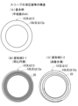
スリーブ(10)の受圧面(10b)の密封構造は、図5(A)~(C)に示す変形例4-1~4-3のように、スリーブ(10)の受圧面(10b)に凹設したリング溝(21)に内嵌されたリングガスケット(22)を用いたものであってもよい。
リングガスケット(22)は、図5(A)に示す変形例4-1ではOリング(22a)が、図5(B)に示す変形例4-2では断面がX字状のXリング(22b)が、図5(C)に示す変形例4-3では断面が三角形の三角リング(22c)がそれぞれ用いられている。
変形例4-1~4-3のリングガスケット(22)を用いると、リング溝(21)内で位置ずれし難いリングガスケット(22)の弾性復元力で、座金(12)の押圧面(12a)とスリーブ(10)の受圧面(10b)の間の密封を確実に行うことができる。
リングガスケット(22)は、ゴムを素材としている。
The sealing structure of the pressure receiving surface (10b) of the sleeve (10) is as shown in Modifications 4-1 to 4-3 shown in FIGS. 5(A) to 5(C). A ring gasket (22) fitted into a recessed ring groove (21) may be used.
The ring gasket (22) is an O-ring (22a) in Modification 4-1 shown in FIG. 5(A), and an X-ring (22b) having an X-shaped cross section in Modification 4-2 shown in FIG. 5(B). ), but in the modified example 4-3 shown in FIG. 5(C), a triangular ring (22c) having a triangular cross section is used.
When the ring gasket (22) of Modifications 4-1 to 4-3 is used, the pressing surface (12a) of the washer (12) is ) and the pressure receiving surface (10b) of the sleeve (10) can be reliably sealed.
The ring gasket (22) is made of rubber.
スリーブ(10)の受圧面(10b)の密封構造は、図5(D)に示す変形例4-4のように、弾性端部(10ab)を用いたものであってもよい。
変形例4-4では、スリーブ(10)は、基端部(10c)側の本体部(10ca)と、突出端部(10a)の一部を構成する弾性端部(10ab)を備え、弾性端部(10ab)と本体部(10ca)を密嵌させ、弾性端部(10ab)は本体部(10ca)及び座金(12)よりも弾性係数の小さい(すなわち弾性変形しやすい)素材で形成され、弾性端部(10ab)に前記スリーブ(10)の受圧面(10b)が形成されている。
The sealing structure of the pressure receiving surface (10b) of the sleeve (10) may be one using an elastic end (10ab) as in Modification 4-4 shown in FIG. 5(D).
In modification 4-4, the sleeve (10) includes a main body (10ca) on the proximal end (10c) side and an elastic end (10ab) that constitutes a part of the protruding end (10a) . The end portion (10ab) and the main body portion (10ca) are tightly fitted, and the elastic end portion (10ab) is made of a material having a smaller elastic modulus (that is, easier to elastically deform) than the main body portion (10ca) and the washer (12). A pressure receiving surface (10b) of the sleeve (10) is formed at the elastic end (10ab).
この変形例4-4の弾性端部(10ab)を用いると、本体部(10ca)に密嵌で位置ずれなく支持された弾性端部(10ab)の弾性復元力で、座金(12)の押圧面(12a)とスリーブ(10)の受圧面(10b)の間の密封を確実に行うことができる。
この場合、弾性端部(10ab)がガスケットの機能を果たすため、スリーブ(10)の受圧面(10b)を密封する専用のガスケットは不要になる。
なお、図3(B)、3(C)の変形例2-1,2-2のように、座金(12)の押圧面(12a)とスリーブ(10)の受圧面(10b)の間は接着剤(17)やグリス(18)で密封してもよい。
本体部(10ca)及び座金(12)の素材を鋼とした場合、弾性端部(10ab)には、鋼よりも弾性係数の小さい銅、アルミ、ゴム、樹脂等を素材とすればよい。
When the elastic end (10ab) of this modification 4-4 is used, the washer (12) is pressed by the elastic restoring force of the elastic end (10ab) that is supported by the main body (10ca) in a tight fit and without displacement. Sealing between the surface (12a) and the pressure receiving surface (10b) of the sleeve (10) can be ensured.
In this case, since the elastic end (10ab) functions as a gasket, there is no need for a dedicated gasket to seal the pressure receiving surface (10b) of the sleeve (10).
In addition, as in Modifications 2-1 and 2-2 of FIGS. 3(B) and 3(C), there is a gap between the pressing surface (12a) of the washer (12) and the pressure receiving surface (10b) of the sleeve (10). It may be sealed with adhesive (17) or grease (18).
When the main body part (10ca) and the washer (12) are made of steel, the elastic end part (10ab) may be made of copper, aluminum, rubber, resin, etc., which have a smaller elastic modulus than steel.
変形例4-4では、弾性端部(10ab)と本体部(10ca)は、入れ子式のインロー構造で密嵌されている。
すなわち、スリーブ(10)の本体部(10ca)は弾性端部(10ab)側の開口周縁に内面が断面L字形の嵌合溝(10cb)を備え、弾性端部(10ab)は、嵌合溝(10cb)と密嵌される筒部(10ac)と、弾性端部(10ab)側の本体部(10ca)の開口端面(10cc)に沿って筒部(10ac)から径方向に張り出されたフランジ部(10ad)を備え、フランジ部(10ad)の開口端面(10ae)がスリーブ(10)の前記受圧面(10b)とされている。
In Modification 4-4, the elastic end (10ab) and main body (10ca) are tightly fitted with a nested spigot structure.
That is, the main body (10ca) of the sleeve (10) is provided with a fitting groove (10cb) having an L-shaped inner surface in cross section on the opening periphery of the elastic end (10ab), and the elastic end (10ab) is provided with a fitting groove (10cb) having an L-shaped cross section. The cylindrical part (10ac) is tightly fitted with the cylindrical part (10cb), and the cylindrical part (10ac) extends in the radial direction along the open end surface (10cc) of the main body part (10ca) on the elastic end (10ab) side. A flange portion (10ad) is provided, and the open end surface (10ae) of the flange portion (10ad) is the pressure receiving surface (10b) of the sleeve (10).
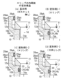
図1(A)のエンジンのスリーブ(10)の内周側は、図6(A)の基本例のようにガスケットがなく、密封機能がないが、スリーブ(10)の内周側に密封機能を持たせるため、図6(B)~(D),図7(A)に示す変形例5-1~5-4のように、スリーブ(10)の内周面(10d)に凹設されたリング溝(23)に内嵌されたリングガスケット(24)による密封構造を用いてもよい。
リングガスケット(24)は、図6(B)に示す変形例5-1ではOリング(24a)が、図6(C)に示す変形例5-2では断面がX字状のXリング(24b)が、図6(D)に示す変形例5-3では断面が三角形の三角リング(24c)が、図7(A)に示す変形例5-4ではシールリップリング(24d)がそれぞれ用いられている。シールリップリング(24d)は、内周にシールリップ(24da)を備えている。
シールリップリング(24d)は、リング溝(23)に圧入されている。リングガスケット(24)は、燃料インジェクタ(7)のノズル部(7d)の外周面(7de)に圧接されている。
The inner circumferential side of the sleeve (10) of the engine in Fig. 1 (A) does not have a gasket and does not have a sealing function like the basic example in Fig. 6 (A), but the inner circumferential side of the sleeve (10) has a sealing function. In order to have this, the inner peripheral surface (10d) of the sleeve (10) is recessed, as shown in Modifications 5-1 to 5-4 shown in FIGS. 6(B) to 7(D) and 7(A). A sealing structure using a ring gasket (24) fitted into the ring groove (23) may also be used.
The ring gasket (24) is an O-ring (24a) in Modification 5-1 shown in FIG. 6(B), and an X-ring (24b) having an X-shaped cross section in Modification 5-2 shown in FIG. 6(C). ), a triangular ring (24c) with a triangular cross section is used in Modification 5-3 shown in FIG. 6(D), and a seal lip ring (24d) is used in Modification 5-4 shown in FIG. 7(A). ing. The seal lip ring (24d) includes a seal lip (24da) on the inner periphery.
The seal lip ring (24d) is press-fitted into the ring groove (23). The ring gasket (24) is pressed against the outer peripheral surface (7de) of the nozzle portion (7d) of the fuel injector (7).
この変形例5-1~5-4のリングガスケット(22)を用いると、リング溝(21)内で位置ずれし難いリングガスケット(22)の弾性復元力で、スリーブ(10)の内周面(10d)と燃料インジェクタ(7)のノズル部(7d)の外周面(7de)との間の密封を確実に行うことができる。 When the ring gasket (22) of Modifications 5-1 to 5-4 is used, the elastic restoring force of the ring gasket (22), which is difficult to displace within the ring groove (21), allows the inner peripheral surface of the sleeve (10) to (10d) and the outer peripheral surface (7de) of the nozzle portion (7d) of the fuel injector (7) can be reliably sealed.
スリーブ(10)の内周側の密封構造は、図7(B)に示す変形例5-5のように、スリーブ(10)の内周面(10d)に焼き付けで固定されたリングガスケット(24)を用いたものであってもよい。
図7(B)に示す変形例5-5では、断面が三角形の三角リング(24c)が用いられている。
この三角リング(24c)は、スリーブ(10)の内周面(10d)の軸長方向に複数配置されている。
三角リング(24c)は、燃料インジェクタ(7)のノズル部(7d)の外周面(7de)に圧接している。
The sealing structure on the inner peripheral side of the sleeve (10) includes a ring gasket (24) fixed to the inner peripheral surface (10d) of the sleeve (10) by baking, as shown in Modification 5-5 shown in FIG. 7(B). ) may be used.
In modification 5-5 shown in FIG. 7(B), a triangular ring (24c) having a triangular cross section is used.
A plurality of these triangular rings (24c) are arranged in the axial direction of the inner peripheral surface (10d) of the sleeve (10).
The triangular ring (24c) is in pressure contact with the outer peripheral surface (7de) of the nozzle portion (7d) of the fuel injector (7).
この変形例5-5のリングガスケット(24)を用いると、焼き付けで位置ずれしないリングガスケット(22)の弾性復元力で、スリーブ(10)の内周面(10d)と燃料インジェクタ(7)のノズル部(7d)の外周面(7de)との間の密封を確実に行うことができる。 When the ring gasket (24) of this modification 5-5 is used, the elastic restoring force of the ring gasket (22), which does not shift due to seizure, allows the inner circumferential surface (10d) of the sleeve (10) and the fuel injector (7) to Sealing between the nozzle portion (7d) and the outer circumferential surface (7de) can be ensured.
スリーブ(10)の内周側の密封構造は、図8(A)に示す変形例6-1のように、スリーブ(10)の内周面(10d)と燃料インジェクタ(7)のノズル部(7d)の外周面(7de)との間に埋め込まれた埋め込みシール(25)を用いたものであってもよい。
埋め込みシール(25)は、スリーブ(10)の内周面(10d)と燃料インジェクタ(7)のノズル部(7d)の外周面(7de)に密着している。
埋め込みシール(25)の素材には、ゴムやアクリル等の樹脂を用いることができる。
The sealing structure on the inner circumferential side of the sleeve (10), as shown in Modification 6-1 shown in FIG. An embedded seal (25) embedded between the outer circumferential surface (7de) of 7d) may be used.
The embedded seal (25) is in close contact with the inner peripheral surface (10d) of the sleeve (10) and the outer peripheral surface (7de) of the nozzle portion (7d) of the fuel injector (7).
As the material of the embedded seal (25), resin such as rubber or acrylic can be used.
この変形例6-1の埋め込みシール(25)を用いると、埋め込みで位置ずれしない埋め込みシール(25)で、スリーブ(10)の内周面(10d)と燃料インジェクタ(7)のノズル部(7d)の外周面(7de)との間の密封を確実に行うことができる。 When the embedded seal (25) of this modification 6-1 is used, the embedded seal (25) does not shift when embedded, and the inner circumferential surface (10d) of the sleeve (10) and the nozzle part (7d) of the fuel injector (7) ) can be reliably sealed with the outer circumferential surface (7de).
スリーブ(10)の内周側の密封構造は、図8(B)に示す変形例6-2のように、スリーブ(10)の内周面(10d)と燃料インジェクタ(7)のノズル部(7d)の外周面(7de)との間に充填された充填シール剤(26)を用いたものであってもよい。
充填シール剤(26)は、スリーブ(10)の内周面(10d)と燃料インジェクタ(7)のノズル部(7d)の外周面(7de)の隙間に充満させる。
充填シール剤(26)の素材には、グリスや樹脂を用いることができる。
スリーブ(10)の周壁は充填シール剤(26)を注入する注入孔(10e)を備えている。
注入孔(10e)は、充填シール剤(26)を注入した後、プラグ(10f)で塞ぐ。
The sealing structure on the inner circumferential side of the sleeve (10) is formed by connecting the inner circumferential surface (10d) of the sleeve (10) and the nozzle portion ( A filling sealing agent (26) filled between the outer circumferential surface (7de) of 7d) and the outer peripheral surface (7de) may be used.
The filling sealant (26) is filled in the gap between the inner circumferential surface (10d) of the sleeve (10) and the outer circumferential surface (7de) of the nozzle portion (7d) of the fuel injector (7).
Grease or resin can be used as the material for the filling sealant (26).
The peripheral wall of the sleeve (10) is provided with an injection hole (10e) for injecting the filling sealant (26).
After filling and sealing agent (26) is injected into the injection hole (10e) , the injection hole (10e) is closed with a plug (10f).
この変形例6-2の充填シール剤(26)を用いると、充満した充填シール剤(26)で、スリーブ(10)の内周面(10d)と燃料インジェクタ(7)のノズル部(7d)の外周面(7de)との間の密封を確実に行うことができる。 When the filling sealing agent (26) of this modification 6-2 is used, the filling sealing agent (26) is filled with the inner peripheral surface (10d) of the sleeve (10) and the nozzle portion (7d) of the fuel injector (7). The sealing between the outer peripheral surface (7de) and the outer circumferential surface (7de) can be ensured.
図1(A)のエンジンでは、座金(12)の外周側は、図9(A)の基本例のように、スリーブ延長カバー(28a)のみで防水防塵が図られているが、図9(B)の変形例7のように、燃料インジェクタ(7)に取り付けられた取り付けカバー(28b)を追加してもよい。
取り付けカバー(28b)は、燃料インジェクタ(7)の本体部(7c)に係止されている。
In the engine shown in Fig. 1(A), the outer peripheral side of the washer (12) is made waterproof and dustproof only by the sleeve extension cover (28a) as in the basic example shown in Fig. 9(A). As in
The mounting cover (28b) is locked to the main body (7c) of the fuel injector (7).
このエンジンでは、取り付けカバー(28b)により、スリーブ延長カバー(28a)の延長端部(28aa)の内周面(28ad)と燃料インジェクタ(7)の本体部(7c)の外周面(7cb)の密封箇所からスリーブ延長カバー(28a)内への防水や防塵を図ることができる。 In this engine, the mounting cover (28b) allows the inner peripheral surface (28ad) of the extension end (28aa) of the sleeve extension cover (28a) to be connected to the outer peripheral surface (7cb) of the main body (7c) of the fuel injector (7). Waterproofing and dustproofing can be achieved from the sealed area into the sleeve extension cover (28a).
図2~図9に示す基本例や変形例は、相互に自由に組み合わせることができる。
図10(A)は図2~図9に示す基本例同士を組み合わせた組み合わせの基本例である。図10(B)は、図3(D)の変形例2-1の接着剤(17)と図5(D)の変形例4-4の弾性端部(10ab)を組み合わせた組み合わせの変形例8である。変形例8には、図4(B)(C)のスリーブの受圧面等の構造、図6(B)~(D),図7(A)(B)のスリーブの内周側の密封構造を組み合わせてもよい。
The basic examples and modified examples shown in FIGS. 2 to 9 can be freely combined with each other.
FIG. 10(A) is a basic example of a combination of the basic examples shown in FIGS. 2 to 9. FIG. 10(B) is a modified example of a combination of the adhesive (17) of Modified Example 2-1 of FIG. 3(D) and the elastic end portion (10ab) of Modified Example 4-4 of FIG. 5(D). It is 8.
次に、燃料インジェクタ(7)の先端配置について説明する。
図1(B)に示すように、燃料インジェクタ(7)は、渦室(2)に臨むノズル部(7d)の先端面(7db)に燃料噴射孔(9)を備えている。
図1(A)に示すように、このエンジンでは、ノズル部(7d)の先端面(7db)の一部が渦室(2)内に突出している。
このエンジンでは、ノズル部(7d)の先端面(7db)の全部が渦室(2)内に突出していてもよい。
Next, the arrangement of the tip of the fuel injector (7) will be explained.
As shown in FIG. 1(B), the fuel injector (7) is provided with a fuel injection hole (9) at the tip surface (7db) of the nozzle portion (7d) facing the vortex chamber (2).
As shown in FIG. 1(A), in this engine, a part of the tip surface (7db) of the nozzle portion (7d) protrudes into the vortex chamber (2).
In this engine, the entire tip surface (7db) of the nozzle portion (7d) may protrude into the vortex chamber (2).
このエンジンでは、図1(A)に示すように、燃料インジェクタ(7)のノズル部(7d)の先端面(7db)の一部または全部が渦室(2)内に突出しているため、図11(A),12(A)に示す燃料噴射孔(9)の出口付近の燃焼火炎が図1(A)に示す旋回流(2a)で吹き流され易く、燃焼火炎の熱で燃料インジェクタ(7)の本体部(7c)内の動弁駆動装置(7ca)の電子部品が過熱され難く、精密な電子燃料噴射制御を行うことができる。 In this engine, as shown in FIG. 1(A), part or all of the tip surface (7db) of the nozzle portion (7d) of the fuel injector (7) protrudes into the vortex chamber (2). The combustion flame near the outlet of the fuel injection hole (9) shown in 11(A) and 12(A) is easily blown away by the swirling flow (2a) shown in FIG. 1(A), and the heat of the combustion flame causes the fuel injector ( The electronic components of the valve drive device (7ca) in the main body (7c) of 7) are not easily overheated, and precise electronic fuel injection control can be performed.
次に、燃料インジェクタ(7)の燃料噴射孔(9)について説明する。
図11は燃料噴射孔(9)の基本例、図12は変形例9に関するものである。
図11(A),12(A)に示すように、燃料噴射孔(9)は先拡がりテーパ形状とされている。
Next, the fuel injection hole (9) of the fuel injector (7) will be explained.
FIG. 11 shows a basic example of the fuel injection hole (9), and FIG. 12 shows a
As shown in FIGS. 11(A) and 12(A), the fuel injection hole (9) has a tapered shape that widens at the front.
このエンジンでは、図11(A),12(A)に示すように、燃料噴射孔(9)は先拡がりテーパ形状であるため、燃料噴射孔(9)の出口で煤が堆積しても、燃料噴射が邪魔され難く、燃料インジェクタ(7)の燃料噴射孔(9)の出口での煤の堆積に拘わらず、精密な燃料噴射制御が行える。 In this engine, as shown in FIGS. 11(A) and 12(A), the fuel injection hole (9) has a tapered shape, so even if soot accumulates at the outlet of the fuel injection hole (9), Fuel injection is less likely to be disturbed, and precise fuel injection control can be performed regardless of soot accumulation at the outlet of the fuel injection hole (9) of the fuel injector (7).
また、このエンジンでは、図1(A)に示すように、燃料インジェクタ(7)のノズル部(7d)の先端面(7db)の一部または全部が渦室(2)内に突出しているため、図11(A),12(A)に示す燃料噴射孔(9)の出口付近の燃焼ガスが図1(A)に示す旋回流(2a)で吹き流され易く、燃焼ガス中の煤が燃料噴射孔(9)の出口で成長し難い。 In addition, in this engine, as shown in Fig. 1(A), part or all of the tip surface (7db) of the nozzle part (7d) of the fuel injector (7) protrudes into the vortex chamber (2). , the combustion gas near the outlet of the fuel injection hole (9) shown in FIGS. 11(A) and 12(A) is easily blown away by the swirling flow (2a) shown in FIG. 1(A), and the soot in the combustion gas is It is difficult to grow at the exit of the fuel injection hole (9).
図1(A)(B)に示すように、燃料インジェクタ(7)のノズル部(7d)の先端面(7db)には、燃料噴射孔(9)の周囲に平坦な渦流ガイド面(7dc)を備えている。
図1(A)に示すように、渦流ガイド面(7dc)の全部が、渦室(2)内に突出している。
このエンジンでは、渦流ガイド面(7dc)の一部が、渦室(2)内に突出していてもよい。
As shown in FIGS. 1(A) and 1(B), a flat vortex guide surface (7dc) is formed around the fuel injection hole (9) on the tip surface (7db) of the nozzle portion (7d) of the fuel injector (7). It is equipped with
As shown in FIG. 1(A), the entire vortex guide surface (7dc) protrudes into the vortex chamber (2).
In this engine, a part of the vortex guide surface (7dc) may protrude into the vortex chamber (2).
図1(A)に示すように、このエンジンでは、渦流ガイド面(7dc)の少なくとも一部が、渦室(2)内に突出しているため、渦室(2)内を旋回する旋回流(2a)が渦流ガイド面(7dc)で案内され、旋回流(2a)が渦室(2)内をスムーズに旋回し、圧縮空気と噴射燃料(13)の混合が良好になり、渦室(2)内で煤が発生し難い。
燃料噴射孔(9)は、ノズル部(7d)の先端面(7db)の中央にある突球面状の最先端面(7dd)に形成されている。
As shown in FIG. 1(A), in this engine, at least a part of the vortex guide surface (7dc) protrudes into the vortex chamber (2), so the swirling flow ( 2a) is guided by the vortex guide surface (7dc), the swirl flow (2a) smoothly swirls inside the vortex chamber (2), the compressed air and the injected fuel (13) are mixed well, and the swirl flow (2a) is guided by the vortex guide surface (7dc). ) is difficult to generate soot.
The fuel injection hole (9) is formed on the most convex surface (7dd) in the center of the distal end surface (7db) of the nozzle portion (7d).
図1(B),11(B),12(B)に示すように、このエンジンでは、燃料インジェクタ(7)1本につき複数個の燃料噴射孔(9)を備えている。
このため、11(B),12(B)に示す噴射燃料(13)が渦室(2)内に広く分散し、圧縮空気と噴射燃料(13)の混合が良好になり、渦室(2)内で煤が発生し難い。
As shown in FIGS. 1(B), 11(B), and 12(B), this engine includes a plurality of fuel injection holes (9) for each fuel injector (7).
Therefore, the injected fuel (13) shown in 11(B) and 12(B) is widely dispersed in the vortex chamber (2), and the mixture of the compressed air and the injected fuel (13) is improved, and the vortex chamber (2) ) is difficult to generate soot.
図1(B),11(B),12(B)に示すように、燃料噴射孔(9)は、燃料インジェクタ(7)1本につき6個設けられている。
このエンジンでは、燃料噴射孔(9)は、燃料インジェクタ(7)1本につき2~6個設けるのが望ましい。
As shown in FIGS. 1(B), 11(B), and 12(B), six fuel injection holes (9) are provided for each fuel injector (7).
In this engine, it is desirable to provide 2 to 6 fuel injection holes (9) for each fuel injector (7).
図1(B)、11(A)、11(B)に示す燃料噴射孔(9)の基本例では、1本の燃料インジェクタ(7)の燃料噴射孔(9)の入口開口(9a)6個の総開口面積をA平方mmとし、1気筒分の排気量をC立方mmとして、前者の値Aを後者の値Cで除したA/Cの値が0.75×10-6となるようにした。具体的には、燃料噴射孔(9)の入口開口(9a)6個の総開口面積Aを0.224平方mm、1気筒分の排気量Cを299000立方mmとした。図12に示す燃料噴射孔(9)の変形例9でも同様にした。
このエンジンでは、A/Cの値が0.5×10-6~1.0×10-6となるようにするのが望ましい。
In the basic example of the fuel injection hole (9) shown in FIGS. 1(B), 11(A), and 11(B), the inlet opening (9a) 6 of the fuel injection hole (9) of one fuel injector (7) Assuming that the total opening area of the cylinders is A square mm and the displacement of one cylinder is C cubic mm, the A/C value obtained by dividing the former value A by the latter value C is 0.75 × 10 -6 . I did it like that. Specifically, the total opening area A of the six inlet openings (9a) of the fuel injection holes (9) was 0.224 square mm, and the displacement C for one cylinder was 299,000 cubic mm. The same thing was done in Modified Example 9 of the fuel injection hole (9) shown in FIG.
In this engine, it is desirable that the A/C value is between 0.5×10 −6 and 1.0×10 −6 .
A/Cの値が0.5×10-6未満の場合には、燃料噴射孔(9)の入口開口(9a)の総開口面積Aが不足し、必要な出力が得られないことがある。A/Cの値が1.0×10-6を越える場合には、燃料噴射孔(9)の入口開口(9a)の総開口面積Aが過大になり、燃料噴射速度が遅く、渦室(2)内で噴射燃料(13)の油滴が微細化せず、圧縮空気と噴射燃料の混合が不良になり、渦室(2)内で煤が発生し易くなる。
これに対し、A/Cの値が0.5×10-6~1.0×10-6の場合には、必要な出力が得られると共に、渦室(2)内で煤が発生し難い。
If the A/C value is less than 0.5×10 -6 , the total opening area A of the inlet opening (9a) of the fuel injection hole (9) may be insufficient, and the necessary output may not be obtained. . When the A/C value exceeds 1.0×10 -6 , the total opening area A of the inlet opening (9a) of the fuel injection hole (9) becomes excessive, the fuel injection speed is slow, and the vortex chamber ( 2) The oil droplets of the injected fuel (13) do not become fine within the vortex chamber (2), resulting in poor mixing of the compressed air and the injected fuel, and soot is likely to be generated within the vortex chamber (2).
On the other hand, when the A/C value is between 0.5×10 -6 and 1.0×10 -6 , the necessary output can be obtained and soot is hardly generated in the vortex chamber (2). .
図11(A)に示す燃料噴射孔(9)の基本例では、1本の燃料インジェクタ(7)の燃料噴射孔(9)の出口開口(9b)6個の総開口面積をB平方mmとし、1本の燃料インジェクタ(7)の燃料噴射孔(9)の入口開口(9a)6個の総開口面積をA平方mmとして、前者の値Bを後者の値Aで除したB/Aの値が1.26(注)参照となるようにした。具体的には、燃料噴射孔(9)の入口開口(9a)6個の総開口面積Aを上記のように、0.224平方mm、燃料噴射孔(9)の出口開口(9b)6個の総開口面積Bを0.282平方mmとした。図12(A)に示す燃料噴射孔(9)の変形例9では、B/Aの値は1.26よりも若干大きくなる。
このエンジンでは、B/Aの値が1.08~1.44となるようにするのが望ましい。
In the basic example of the fuel injection hole (9) shown in FIG. 11(A), the total opening area of the six outlet openings (9b) of the fuel injection hole (9) of one fuel injector (7) is assumed to be B square mm. , assuming that the total opening area of the six inlet openings (9a) of the fuel injection holes (9) of one fuel injector (7) is A square mm, the former value B is divided by the latter value A, which is B/A. The value has been changed to 1.26 (see note). Specifically, the total opening area A of the six inlet openings (9a) of the fuel injection hole (9) is 0.224 square mm, and the six outlet openings (9b) of the fuel injection hole (9) are as described above. The total opening area B was 0.282 square mm. In
In this engine, it is desirable that the B/A value is between 1.08 and 1.44.
B/Aの値が1.08未満の場合には、燃料噴射孔(9)の入口開口(9a)の総開口面積Aに対して出口開口(9b)の総開口面積Bが小さ過ぎ、燃料噴射孔(9)の出口で堆積した少量の煤で燃料噴射が邪魔され、燃料噴射制御の精度が低下するおそれがある。
B/Aの値が1.44を超える場合には、燃料噴射孔(9)の入口開口(9a)の総開口面積Aに対して出口開口(9b)の総開口面積Bが大き過ぎ、燃料噴射孔(9)の出口で煤の堆積物の成長速度が速く、多量の煤の堆積物で燃料噴射が邪魔され、燃料噴射制御の精度が低下するおそれがある。
これに対し、B/Aの値が1.08~1.44である場合には、少量の煤の堆積物では燃料噴射が邪魔されないうえ、燃料噴射孔(9)の出口での煤の堆積物の成長速度が遅く、燃料噴射制御の精度が低下し難い。
If the value of B/A is less than 1.08, the total opening area B of the outlet opening (9b) is too small compared to the total opening area A of the inlet opening (9a) of the fuel injection hole (9), and the fuel A small amount of soot deposited at the outlet of the injection hole (9) may interfere with fuel injection and reduce the accuracy of fuel injection control.
If the value of B/A exceeds 1.44, the total opening area B of the outlet opening (9b) is too large compared to the total opening area A of the inlet opening (9a) of the fuel injection hole (9), and the fuel The growth rate of soot deposits at the outlet of the injection hole (9) is fast, and a large amount of soot deposits may obstruct fuel injection and reduce the accuracy of fuel injection control.
On the other hand, when the B/A value is between 1.08 and 1.44, fuel injection is not hindered by a small amount of soot deposits, and soot deposits at the exit of the fuel injection hole (9) The growth rate of substances is slow, and the accuracy of fuel injection control is less likely to deteriorate.
B/Aの値が1.44を超える場合に、燃料噴射孔(9)の出口で煤の堆積物の成長速度が速くなるのに対し、1.44以下でその成長速度が遅くなる理由は、次のように推定される。すなわち、前者では燃料噴射孔(9)の出口で噴射燃料(13)の周囲に形成される隙間(9h)が過大になり、この隙間(9h)に煤を含む燃焼ガスが多量に流入し、煤の堆積物が急速に成長するのに対し、後者では燃料噴射孔(9)の出口で噴射燃料(13)の周囲に形成される隙間(9h)が適度な大きさになり、煤の堆積物の成長速度と噴射燃料(13)による煤の堆積物の除去速度が拮抗し、燃料噴射孔(9)の出口で成長した煤の堆積物が直ぐに噴射燃料で除去されるためと推定される。 The reason why the growth rate of soot deposits at the exit of the fuel injection hole (9) becomes faster when the value of B/A exceeds 1.44, whereas the growth rate slows down when the value is 1.44 or less. , is estimated as follows. That is, in the former case, the gap (9h) formed around the injected fuel (13) at the exit of the fuel injection hole (9) becomes too large, and a large amount of combustion gas containing soot flows into this gap (9h). Whereas soot deposits grow rapidly, in the latter case, the gap (9h) formed around the injected fuel (13) at the exit of the fuel injection hole (9) becomes a moderate size, and soot deposits grow rapidly. This is presumed to be because the growth rate of the substance and the removal rate of soot deposits by the injected fuel (13) are comparable, and the soot deposits that have grown at the outlet of the fuel injection hole (9) are immediately removed by the injected fuel. .
図2(C)に示すように、このエンジンでは、インジェクタ中心軸線(7a)の渦室側延長線(7b)が連通口(5)を通過し、図11(B)に示すように、複数個(6個)の燃料噴射孔(9)は、インジェクタ中心軸線(7a)の周囲に配置され、図11(C)に示すように、複数個(6個)の燃料噴射孔(9)の噴射孔中心軸線(9c)の渦室側延長線(9d)の全本数(6本)が連通口(5)を通過するようにしている。
このエンジンでは、渦室側延長線(9d)の全本数(6本)の一部のみが連通口(5)を通過するようにしてもよい。
このエンジンでは、多くの噴射燃料(13)が連通口(5)を介して主燃焼室(4)に噴射されるため、渦室(2)での過剰な燃焼が防止され、渦室(2)で煤が発生し難い。
複数個(6個)の燃料噴射孔(9)は、インジェクタ中心軸線(7a)の周囲で、インジェクタ先端面(8)の最先端突出面(8a)の周方向に一定間隔を保持して配置されている。
As shown in FIG. 2(C), in this engine, the vortex chamber side extension line (7b) of the injector center axis (7a) passes through the communication port (5), and as shown in FIG. 11(B), multiple The (6) fuel injection holes (9) are arranged around the injector center axis (7a), and as shown in FIG. 11(C), the plural (6) fuel injection holes (9) The total number (six) of the extension lines (9d) on the vortex chamber side of the injection hole center axis (9c) are made to pass through the communication port (5).
In this engine, only a part of the total number (six) of the vortex chamber side extension lines (9d) may pass through the communication port (5).
In this engine, a large amount of injected fuel (13) is injected into the main combustion chamber (4) through the communication port (5), so excessive combustion in the vortex chamber (2) is prevented and the vortex chamber (2) is injected into the main combustion chamber (4). ), it is difficult to generate soot.
A plurality of (six) fuel injection holes (9) are arranged at constant intervals around the injector center axis (7a) in the circumferential direction of the most protruding surface (8a) of the injector tip surface (8). has been done.
図12に示す変形例9の燃料噴射孔(9)では、図12(C)に示すように、インジェクタ中心軸線(7a)の渦室側延長線(7b)は連通口(5)を通過し、図12(B)に示すように、各燃料インジェクタ(7)の複数個(6個)の燃料噴射孔(9)は、各インジェクタ中心軸線(7a)の周囲に配置され、図12(C)に示すように、各燃料インジェクタ(7)の複数個(6個)の燃料噴射孔(9)の噴射孔中心軸線(9c)の渦室側延長線(9d)の一部本数(5本)が連通口(5)の渦室側開口(5a)の周縁部(5b)に突き当たるようにしている。残り本数(1本)は、連通口(5)を貫通している。
このエンジンでは、全本数(6本)が連通口(5)の渦室側開口(5a)の周縁部(5b)に突き当たるようにしてもよい。
このエンジンでは、多くの噴射燃料(13)が連通口(5)を介して主燃焼室(4)に噴射されるため、渦室(2)での過剰な燃焼が防止され、渦室(2)で煤が発生し難い。
In the fuel injection hole (9) of
In this engine, the total number (six) may abut against the peripheral edge (5b) of the vortex chamber side opening (5a) of the communication port (5).
In this engine, since a large amount of injected fuel (13) is injected into the main combustion chamber (4) through the communication port (5), excessive combustion in the vortex chamber (2) is prevented and the vortex chamber (2) is injected into the main combustion chamber (4). ), it is difficult to generate soot.
図12(C)に示すように、変形例9の燃料噴射孔(9)では、インジェクタ中心軸線(7a)の渦室側延長線(7b)と平行な向きに見て、相互に直交する前後方向と横方向の各寸法とをそれぞれ1.5倍ずつ拡大した渦室側開口(5a)と相似形の相似形仮想線(5c)を想定し、この相似形仮想線(5c)と渦室側開口(5a)との間の渦室内周面が、燃料噴射孔(9)の噴射孔中心軸線(9c)の渦室側延長線(9d)が突き当たる渦室側開口(5a)の周縁部(5b)とされている。
図12に示す燃料噴射孔(9)の変形例9では、図11に示す燃料噴射孔(9)の基本例と同一の要素には、図11と同一の符号を付しておく。図12に示す燃料噴射孔(9)の変形例の要素は、特記しない限り、図11に示す燃料噴射孔(9)の基本例の要素と同一の構造と機能を備える。
As shown in FIG. 12(C), in the fuel injection hole (9) of Modification Example 9, the front and rear sides are perpendicular to each other when viewed in a direction parallel to the vortex chamber side extension line (7b) of the injector center axis (7a). Assuming a similar imaginary line (5c) similar to the vortex chamber side opening (5a) in which each dimension in the direction and lateral direction is enlarged by 1.5 times, this similar imaginary line (5c) and the vortex chamber The peripheral surface of the vortex chamber between the side opening (5a) and the vortex chamber side opening (5a) is the peripheral edge of the vortex chamber side opening (5a) where the vortex chamber side extension line (9d) of the injection hole center axis (9c) of the fuel injection hole (9) abuts. (5b).
In
渦室(2)での煤の発生状況を調べたところ、複数個(6個)の燃料噴射孔(9)の噴射孔中心軸線(9c)の渦室側延長線(9d)の全本数(6本)が連通口(5)を通過する図11の基本例や、一部本数(5本)が連通口(5)の渦室側開口(5a)の周縁部(5b)に突き当たる図12の変形例9では、全本数(6本)が渦室側開口(105a)の周縁部(105b)の外側に突き当たる図15(C)の第3比較例に比べ、渦室(2)での煤の発生量が少なかった。
図15に示す第3比較例では、図11に示す基本例や図12に示す変形例と同一の要素には、図11,12の符号に100を加算した符号を付しておく。図13に示す第1比較例や図14に示す第2比較例でも、同様にしておく。
When we investigated the soot generation situation in the vortex chamber (2), we found that the total number of extension lines (9d) on the vortex chamber side of the injection hole center axis (9c) of the multiple (6) fuel injection holes (9) ( The basic example shown in Fig. 11 where 6 pieces) pass through the communication port (5), and Fig. 12 where some of the pieces (5 pieces) abut against the peripheral edge (5b) of the vortex chamber side opening (5a) of the communication port (5). In Modified Example 9, compared to the third comparative example of FIG. The amount of soot generated was small.
In the third comparative example shown in FIG. 15, the same elements as the basic example shown in FIG. 11 and the modified example shown in FIG. 12 are given the same reference numerals as those in FIGS. The same applies to the first comparative example shown in FIG. 13 and the second comparative example shown in FIG. 14.
図11(A)に示すように、燃料噴射孔(9)の基本例では、インジェクタ中心軸線(7a)に対する各噴射孔中心軸線(9c)(またはその渦室側延長線(9d))の拡開角度(α)は、4°とされている。
図12(A)に示すように、燃料噴射孔(9)の変形例9では、インジェクタ中心軸線(7a)に対する各噴射孔中心軸線(9c)(またはその渦室側延長線(9d))の拡開角度(α)は、7°とされている。
このエンジンでは、インジェクタ中心軸線(7a)に対する各噴射孔中心軸線(9c)(またはその渦室側延長線(9d))の拡開角度(α)は、4°~7°とするのが望ましい。
As shown in FIG. 11(A), in the basic example of the fuel injection hole (9), the center axis (9c) of each injection hole (or its extension on the vortex chamber side (9d)) is expanded with respect to the injector center axis (7a). The opening angle (α) is 4°.
As shown in FIG. 12(A), in
In this engine, the expansion angle (α) of each injection hole center axis (9c) (or its extension on the vortex chamber side (9d)) with respect to the injector center axis (7a) is preferably 4° to 7°. .
拡開角度(α)が4°未満である場合には、複数の噴射燃料(13)の一部同士が重なり合い易く、渦室(2)内で煤が発生し易くなる。
拡開角度(α)が7°を越える場合には、噴射燃料(13)の多くが連通口(5)を通過せずに渦室(2)の内面に衝突し、渦室(2)内での過剰な燃焼で煤が発生し易い。
これに対し、拡開角度(α)が4°~7°である場合には、渦室(2)内で煤が発生し難い。
When the expansion angle (α) is less than 4°, parts of the plurality of injected fuels (13) are likely to overlap each other, and soot is likely to be generated within the vortex chamber (2).
When the expansion angle (α) exceeds 7°, most of the injected fuel (13) does not pass through the communication port (5) and collides with the inner surface of the vortex chamber (2). Soot is likely to be generated due to excessive combustion.
On the other hand, when the expansion angle (α) is 4° to 7°, soot is hardly generated in the vortex chamber (2).
渦室(2)内での煤の発生状況を調べたところ、拡開角度(α)が4°の基本例(図11)や7°の変形例9(図12)では、0°の第1比較例(図13)や1°の第2比較例(図14)や10°の第3比較例(図15)に比べ、渦室(2)内での煤の発生が少なかった。 When we investigated the soot generation situation in the vortex chamber (2), we found that in the basic example (Fig. 11) where the expansion angle (α) is 4° and the modified example 9 (Fig. 12) where the expansion angle (α) is 7°, the expansion angle (α) is 0°. Compared to the 1st comparative example (FIG. 13), the 1° second comparative example (FIG. 14), and the 10° third comparative example (FIG. 15), less soot was generated in the vortex chamber (2).
図11(A)に示す基本例の燃料噴射孔(9)では、各燃料噴射孔(9)のテーパ角度(β)は、12°とされている。
図12(A)に示す燃料噴射孔(9)の変形例9では、各燃料噴射孔(9)のテーパ角度(β)は、18°とされている。
このエンジンでは、テーパ角度(β)は、12°~18°とするのが望ましい。
In the fuel injection holes (9) of the basic example shown in FIG. 11(A), the taper angle (β) of each fuel injection hole (9) is 12°.
In
In this engine, the taper angle (β) is preferably 12° to 18°.
テーパ角度(β)が12°未満の場合には、燃料噴射孔(9)の入口開口(9a)に対して出口開口(9b)が小さ過ぎ、燃料噴射孔(9)の出口で堆積した少量の煤で燃料噴射が邪魔され、燃料噴射制御の精度が低下するおそれがある。
テーパ角度(β)が18°を超える場合には、燃料噴射孔(9)の入口開口(9a)に対して出口開口(9b)が大き過ぎ、燃料噴射孔(9)の出口で煤の堆積物の成長速度が速く、多量の煤の堆積物で燃料噴射が邪魔され、燃料噴射制御の精度が低下するおそれがある。
これに対し、テーパ角度(β)が12°~18°の場合には、少量の煤の堆積物では燃料噴射が邪魔されないうえ、燃料噴射孔(9)の出口での煤の堆積物の成長速度が遅く、燃料噴射制御の精度が低下し難い。
If the taper angle (β) is less than 12°, the outlet opening (9b) is too small compared to the inlet opening (9a) of the fuel injection hole (9), and a small amount of dirt may accumulate at the outlet of the fuel injection hole (9). The soot may interfere with fuel injection, reducing the accuracy of fuel injection control.
If the taper angle (β) exceeds 18°, the outlet opening (9b) is too large relative to the inlet opening (9a) of the fuel injection hole (9), and soot may accumulate at the outlet of the fuel injection hole (9). The growth rate of soot is fast, and a large amount of soot deposits may obstruct fuel injection and reduce the accuracy of fuel injection control.
On the other hand, when the taper angle (β) is between 12° and 18°, fuel injection is not hindered by a small amount of soot deposits, and the soot deposits grow at the exit of the fuel injection hole (9). The speed is slow and the accuracy of fuel injection control is less likely to decrease.
燃料噴射孔(9)の出口での煤の堆積物の成長速度を調べたところ、テーパ角度(β)が12°の基本例(図11)や18°の変形例9(図12)では、0°の第1比較例(図13)や6°の第2比較例(図14)や24°の第3比較例(図15)に比べ、燃料噴射孔(9)の出口での煤の堆積物の成長速度が遅かった。 When we investigated the growth rate of soot deposits at the outlet of the fuel injection hole (9), we found that in the basic example (Fig. 11) where the taper angle (β) is 12° and the modified example 9 (Fig. 12) where the taper angle (β) is 18°. Compared to the first comparative example at 0° (Fig. 13), the second comparative example at 6° (Fig. 14), and the third comparative example at 24° (Fig. 15), the amount of soot at the outlet of the fuel injection hole (9) was The growth rate of the deposit was slow.
図15の第3比較例のように、テーパ角度(β)が18°を超える場合に、燃料噴射孔(109)の出口で煤の堆積物の成長速度が速くなるのに対し、図11の基本例や図12の変形例9のように、テーパ角度(β)が18°以下では、その成長速度が遅くなる理由は、次のように推定される。すなわち、前者では燃料噴射孔(109)の出口で噴射燃料(113)の周囲に比較的大きな隙間(109h)が形成され、この大きな隙間(109h)に煤を含む燃焼ガスが多量に流入し、煤の堆積物が急速に成長するのに対し、後者では燃料噴射孔(9)の出口で噴射燃料(13)の周囲の隙間(9h)が適度な大きさになり、煤の堆積物の成長速度と噴射燃料(13)による煤の堆積物の除去速度が拮抗し、燃料噴射孔(9)の出口で成長した煤の堆積物が直ぐに噴射燃料で除去されるためと推定される。
As in the third comparative example in FIG. 15, when the taper angle (β) exceeds 18°, the growth rate of soot deposits increases at the outlet of the fuel injection hole (109), whereas The reason why the growth rate becomes slow when the taper angle (β) is 18° or less, as in the basic example and
図11(A)に示すように、燃料噴射孔(9)の基本例では、インジェクタ中心軸線(7a)と、インジェクタ中心軸線(7a)に沿う各噴射孔内周面(9g)との挟角(γ)は、1°とされている。
図12(A)に示すように、燃料噴射孔(9)の変形例9では、インジェクタ中心軸線(7a)と、インジェクタ中心軸線(7a)に沿う各噴射孔内周面(9g)との挟角(γ)は、3°とされている。
このエンジンでは、挟角(γ)は、1°~3°とするのが望ましい。
As shown in FIG. 11(A), in the basic example of the fuel injection hole (9), the included angle between the injector center axis (7a) and the inner circumferential surface (9g) of each injection hole along the injector center axis (7a) is (γ) is assumed to be 1°.
As shown in FIG. 12(A), in the
In this engine, the included angle (γ) is preferably 1° to 3°.
挟角(γ)が1°未満である場合には、複数の噴射燃料(13)の一部同士が重なり合い易く、渦室(2)内で煤が発生し易くなる。拡開角度(α)が3°を越える場合には、噴射燃料(13)の多くが連通口(5)を通過せずに渦室(2)の内面に衝突し、渦室(2)内での過剰な燃焼で煤が発生し易い。
これに対し、挟角(γ)が1°~3°である場合には、渦室(2)内で煤が発生し難い。
When the included angle (γ) is less than 1°, parts of the plurality of injected fuels (13) are likely to overlap each other, and soot is likely to be generated within the vortex chamber (2). When the expansion angle (α) exceeds 3°, most of the injected fuel (13) does not pass through the communication port (5) and collides with the inner surface of the vortex chamber (2). Soot is likely to be generated due to excessive combustion.
On the other hand, when the included angle (γ) is 1° to 3°, soot is hardly generated within the vortex chamber (2).
渦室(2)内での煤の発生状況を調べたところ、挟角(γ)が1°の基本例(図11)や3°の変形例9(図12)では、0°の第1比較例(図13)や4°の比較例(図示せず)に比べ渦室(2)内での煤の発生量が少なかった。 When we investigated the soot generation situation in the vortex chamber (2), we found that in the basic example (Fig. 11) where the included angle (γ) is 1° and the modified example 9 (Fig. 12) where the included angle (γ) is 3°, the first Compared to the comparative example (FIG. 13) and the 4° comparative example (not shown), the amount of soot generated in the vortex chamber (2) was smaller.
図11(A)に示すように、燃料噴射孔(9)の基本例では、燃料噴射孔(9)の入口開口縁(9e)は、面取り仕上げされていない先鋭なピン角(9f)を備えている。
図12(A)に示す燃料噴射孔(9)の変形例9でも、燃料噴射孔(9)の入口開口縁(9e)は、面取り仕上げされていない先鋭なピン角(9f)を備えている。
As shown in FIG. 11(A), in the basic example of the fuel injection hole (9), the inlet opening edge (9e) of the fuel injection hole (9) has a sharp pin angle (9f) that is not chamfered. ing.
Also in
このエンジンでは、燃料噴射孔(9)の入口開口縁(9e)は、面取り仕上げされていない先鋭なピン角(9f)を残すことにより、面取り仕上げが不要になり、燃料インジェクタ(7)の製作が容易になる。
また、このエンジンでは、燃料インジェクタ(7)は渦室(2)に燃料を噴射するため、直噴式のものに比べ、燃料噴射圧が低くて済み、燃料の噴射圧によるピン角(9f)の摩耗が起こり難く、これに起因する燃料噴射精度の低下は起こり難い。
In this engine, the inlet opening edge (9e) of the fuel injection hole (9) is left with a sharp pin angle (9f) that is not chamfered, thereby eliminating the need for chamfering and manufacturing the fuel injector (7). becomes easier.
In addition, in this engine, the fuel injector (7) injects fuel into the vortex chamber (2), so the fuel injection pressure is lower than that of a direct injection type, and the pin angle (9f) due to the fuel injection pressure is reduced. Wear is less likely to occur, and fuel injection accuracy is less likely to deteriorate due to this.
上記ピン角(9f)はRが0.1mm以下の先鋭形状の開口縁である。 The pin angle (9f) is a sharp opening edge with an R of 0.1 mm or less.
(1)…シリンダヘッド、(1a)…挿通孔、(1b)…エンジン冷却風路、(2)…渦室、(3)…シリンダ、(4)…主燃焼室、(5)…連通口、(6)…挿通孔、 (7)…燃料インジェクタ、(7c)…本体部、(7cb)…外周面、(7d)…ノズル部、(7db)…先端面、(7dc)…渦流ガイド面、(10)…スリーブ、(10a)…突出端部、(10b)…受圧面、(11)…押圧力、(12)…座金、(12a)…押圧面、(17)…接着剤、(18)…グリス、(19)…シートガスケット、(20)…溝、(28a)…スリーブ延長カバー、(28aa)…延長端部、(28ac)…リングガスケット、(28ad)…内周面。 (1)...Cylinder head, (1a)...Insertion hole, (1b)...Engine cooling air passage, (2)...Vortex chamber, (3)...Cylinder, (4)...Main combustion chamber, (5)...Communication port , (6)...Insertion hole, (7)...Fuel injector, (7c)...Body part, (7cb)...Outer peripheral surface, (7d)...Nozzle part, (7db)...Tip surface, (7dc)...Vortex guide surface , (10)...Sleeve, (10a)...Protruding end, (10b)...Pressure receiving surface, (11)...Press force, (12)...Washer, (12a)...Press surface, (17)...Adhesive, ( 18) Grease, (19) Sheet gasket, (20) Groove, (28a) Sleeve extension cover, (28aa) Extension end, (28ac) Ring gasket, (28ad) Inner peripheral surface.
Claims (8)
挿通孔(1a)からシリンダヘッド(1)外に突出するスリーブ(10)と、スリーブ(10)の突出端部(10a)に設けられた受圧面(10b)を備え、
燃料インジェクタ(7)は、径大の本体部(7c)と、径小のノズル部(7d)と、本体部(7c)とノズル部(7d)の段差部分に形成された押圧面(7e)を備え、
燃料インジェクタ(7)のノズル部(7d)がスリーブ(10)内から挿通孔(1a)内に亘って挿通され、燃料インジェクタ(7)が押圧力(11)で渦室(2)側に押圧され、燃料インジェクタ(7)にかかる押圧力(11)が燃料インジェクタ(7)の押圧面(7e)から座金(12)を介してスリーブ(10)の受圧面(10b)で受け止められるように構成され、
スリーブ(10)は、突出端部(10a)から突出方向に延長されたスリーブ延長カバー(28a)を備え、スリーブ延長カバー(28a)で座金(12)が外周側から覆われ、
スリーブ延長カバー(28a)の延長端部(28aa)に燃料インジェクタ(7)の本体部(7c)が内嵌され、
スリーブ延長カバー(28a)の延長端部(28aa)の内周面(28ad)と、燃料インジェクタ(7)の本体部(7c)の外周面(7cb)の間は、リングガスケット(28ac)で密封されている、ことを特徴とするディーゼルエンジン。 A cylinder (3), a cylinder head (1), a vortex chamber (2) in the cylinder head (1), a main combustion chamber (4) in the cylinder (3), a main combustion chamber (4) and a vortex chamber. (2), an insertion hole (1a) in the cylinder head (1) facing the vortex chamber (2), and a fuel injector (7) inserted into the insertion hole (1a). In addition, in diesel engines,
A sleeve (10) protruding from the insertion hole (1a) to the outside of the cylinder head (1), and a pressure receiving surface (10b) provided at the protruding end (10a) of the sleeve (10),
The fuel injector (7) includes a main body part (7c) with a large diameter, a nozzle part (7d) with a small diameter, and a pressing surface (7e) formed at a step between the main body part (7c) and the nozzle part (7d). Equipped with
The nozzle part (7d) of the fuel injector (7) is inserted from the inside of the sleeve (10) into the insertion hole (1a), and the fuel injector (7) is pressed toward the vortex chamber (2) by the pressing force (11). The pressure force (11) applied to the fuel injector (7) is received from the pressure surface (7e) of the fuel injector (7) via the washer (12) by the pressure receiving surface (10b) of the sleeve (10). is,
The sleeve (10) includes a sleeve extension cover (28a) extending from the projecting end (10a) in the projecting direction, and the sleeve extension cover (28a) covers the washer (12) from the outer peripheral side.
The main body (7c) of the fuel injector (7) is fitted into the extension end (28aa) of the sleeve extension cover (28a),
The inner peripheral surface (28ad) of the extended end (28aa) of the sleeve extension cover (28a) and the outer peripheral surface (7cb) of the main body (7c) of the fuel injector (7) are sealed with a ring gasket (28ac). A diesel engine characterized by:
エンジン冷却風路(1b)を備え、エンジン冷却風路(1b)内で、燃料インジェクタ(7)の本体部(7c)の外周面(7cb)とスリーブ(10)の外周面(10g)が露出している、ことを特徴とするディーゼルエンジン。 The diesel engine according to claim 1 ,
Equipped with an engine cooling air path (1b), the outer peripheral surface (7cb) of the main body (7c) of the fuel injector (7) and the outer peripheral surface (10g) of the sleeve (10) are exposed within the engine cooling air path (1b). This diesel engine is characterized by:
スリーブ(10)は、シリンダヘッド(1)とは別部品で構成され、シリンダヘッド(1)に取り付けられている、ことを特徴とするディーゼルエンジン。 In the diesel engine according to claim 1 or claim 2 ,
A diesel engine characterized in that the sleeve (10) is a separate part from the cylinder head (1) and is attached to the cylinder head (1).
座金(12)の押圧面(12a)とスリーブ(10)の受圧面(10b)との間が、接着剤(17)で密封されている、ことを特徴とするディーゼルエンジン。 The diesel engine according to any one of claims 1 to 3 ,
A diesel engine characterized in that a pressure surface (12a) of a washer (12) and a pressure receiving surface (10b) of a sleeve (10) are sealed with an adhesive (17).
座金(12)の押圧面(12a)とスリーブ(10)の受圧面(10b)との間が、グリス(18)で密封されている、ことを特徴とするディーゼルエンジン。 The diesel engine according to any one of claims 1 to 3 ,
A diesel engine characterized in that the space between the pressing surface (12a) of the washer (12) and the pressure receiving surface (10b) of the sleeve (10) is sealed with grease (18).
座金(12)の押圧面(12a)とスリーブ(10)の受圧面(10b)との間が、シートガスケット(19)で密封されている、ことを特徴とするディーゼルエンジン。 The diesel engine according to any one of claims 1 to 3 ,
A diesel engine characterized in that the space between the pressing surface (12a) of the washer (12) and the pressure receiving surface (10b) of the sleeve (10) is sealed with a sheet gasket (19).
スリーブ(10)の受圧面(10b)と座金(12)の押圧面(12a)の一方または両方に、その周方向に伸びる同心円形または渦巻き形の溝(20)が形成されている、ことを特徴とするディーゼルエンジン。 The diesel engine according to any one of claims 1 to 6 ,
Concentric circular or spiral grooves (20) extending in the circumferential direction are formed on one or both of the pressure receiving surface (10b) of the sleeve (10) and the pressing surface (12a) of the washer (12). Features a diesel engine.
渦室(2)に臨むノズル部(7d)の先端面(7db)に燃料噴射孔(9)を備え、
ノズル部(7d)の先端面(7db)の一部または全部が渦室(2)内に突出している、ことを特徴とするディーゼルエンジン。 The diesel engine according to any one of claims 1 to 7 ,
A fuel injection hole (9) is provided on the tip surface (7db) of the nozzle part (7d) facing the vortex chamber (2),
A diesel engine characterized in that a part or all of the tip surface (7db) of the nozzle part (7d) protrudes into the vortex chamber (2).
Priority Applications (1)
| Application Number | Priority Date | Filing Date | Title |
|---|---|---|---|
| JP2020218647A JP7366879B2 (en) | 2020-12-28 | 2020-12-28 | diesel engine |
Applications Claiming Priority (1)
| Application Number | Priority Date | Filing Date | Title |
|---|---|---|---|
| JP2020218647A JP7366879B2 (en) | 2020-12-28 | 2020-12-28 | diesel engine |
Publications (2)
| Publication Number | Publication Date |
|---|---|
| JP2022103795A JP2022103795A (en) | 2022-07-08 |
| JP7366879B2 true JP7366879B2 (en) | 2023-10-23 |
Family
ID=82279660
Family Applications (1)
| Application Number | Title | Priority Date | Filing Date |
|---|---|---|---|
| JP2020218647A Active JP7366879B2 (en) | 2020-12-28 | 2020-12-28 | diesel engine |
Country Status (1)
| Country | Link |
|---|---|
| JP (1) | JP7366879B2 (en) |
Citations (4)
| Publication number | Priority date | Publication date | Assignee | Title |
|---|---|---|---|---|
| JP2000248940A (en) | 1999-03-02 | 2000-09-12 | Yamaha Motor Co Ltd | Engine with auxiliary chamber |
| JP2007162678A (en) | 2005-11-16 | 2007-06-28 | Toyota Motor Corp | Fuel injection valve |
| JP2018189043A (en) | 2017-05-09 | 2018-11-29 | いすゞ自動車株式会社 | Injector for engine |
| JP2020084846A (en) | 2018-11-20 | 2020-06-04 | ヤンマー株式会社 | Auxiliary chamber diesel engine |
-
2020
- 2020-12-28 JP JP2020218647A patent/JP7366879B2/en active Active
Patent Citations (4)
| Publication number | Priority date | Publication date | Assignee | Title |
|---|---|---|---|---|
| JP2000248940A (en) | 1999-03-02 | 2000-09-12 | Yamaha Motor Co Ltd | Engine with auxiliary chamber |
| JP2007162678A (en) | 2005-11-16 | 2007-06-28 | Toyota Motor Corp | Fuel injection valve |
| JP2018189043A (en) | 2017-05-09 | 2018-11-29 | いすゞ自動車株式会社 | Injector for engine |
| JP2020084846A (en) | 2018-11-20 | 2020-06-04 | ヤンマー株式会社 | Auxiliary chamber diesel engine |
Also Published As
| Publication number | Publication date |
|---|---|
| JP2022103795A (en) | 2022-07-08 |
Similar Documents
| Publication | Publication Date | Title |
|---|---|---|
| EP0184049B1 (en) | Intermittent type swirl injection nozzle | |
| EP2148082B1 (en) | Coupling arrangement for an injection valve and injection valve | |
| JP5145423B2 (en) | Fuel injection device | |
| US8967099B2 (en) | Two-stroke engine | |
| ATE387578T1 (en) | FUEL INJECTION VALVE | |
| US8313048B2 (en) | Fuel injector | |
| KR20010102344A (en) | Fuel injector with turbulence generator for fuel orifice | |
| US7124963B2 (en) | Low pressure fuel injector nozzle | |
| US20040060538A1 (en) | Fuel injection valve and internal combustion engine mounting the same | |
| CA2218695C (en) | Fuel injection device for internal combustion engines | |
| US7137577B2 (en) | Low pressure fuel injector nozzle | |
| JP4089577B2 (en) | In-cylinder injector | |
| JP2010101290A (en) | Fuel injection valve | |
| JP7366879B2 (en) | diesel engine | |
| US7540435B2 (en) | Pressure-effected interconnection of a metal part and a plastic part | |
| US9133803B2 (en) | Fuel injector having a plurality of flow-through regions | |
| US6830035B2 (en) | Structure of installing injector in common rail and method of the same | |
| JP7366880B2 (en) | diesel engine | |
| JP7348891B2 (en) | electronic fuel injection diesel engine | |
| JP2008511787A (en) | High pressure pump for fuel injection device of internal combustion engine | |
| JP7397787B2 (en) | Diesel engine and its manufacturing method | |
| WO2008010037A2 (en) | Fuel injection device | |
| EP1188920A3 (en) | Internal combustion engine | |
| JP3385415B2 (en) | High pressure fuel pipe connection structure | |
| US5315870A (en) | Housing for an air flow rate meter |
Legal Events
| Date | Code | Title | Description |
|---|---|---|---|
| A621 | Written request for application examination |
Free format text: JAPANESE INTERMEDIATE CODE: A621 Effective date: 20221229 |
|
| A977 | Report on retrieval |
Free format text: JAPANESE INTERMEDIATE CODE: A971007 Effective date: 20230913 |
|
| A131 | Notification of reasons for refusal |
Free format text: JAPANESE INTERMEDIATE CODE: A131 Effective date: 20230919 |
|
| A521 | Request for written amendment filed |
Free format text: JAPANESE INTERMEDIATE CODE: A523 Effective date: 20230929 |
|
| TRDD | Decision of grant or rejection written | ||
| A01 | Written decision to grant a patent or to grant a registration (utility model) |
Free format text: JAPANESE INTERMEDIATE CODE: A01 Effective date: 20231010 |
|
| A61 | First payment of annual fees (during grant procedure) |
Free format text: JAPANESE INTERMEDIATE CODE: A61 Effective date: 20231011 |
|
| R150 | Certificate of patent or registration of utility model |
Ref document number: 7366879 Country of ref document: JP Free format text: JAPANESE INTERMEDIATE CODE: R150 |