JP7363849B2 - steering wheel - Google Patents
steering wheel Download PDFInfo
- Publication number
- JP7363849B2 JP7363849B2 JP2021058401A JP2021058401A JP7363849B2 JP 7363849 B2 JP7363849 B2 JP 7363849B2 JP 2021058401 A JP2021058401 A JP 2021058401A JP 2021058401 A JP2021058401 A JP 2021058401A JP 7363849 B2 JP7363849 B2 JP 7363849B2
- Authority
- JP
- Japan
- Prior art keywords
- assembly
- contact
- locking
- holder
- steering wheel
- Prior art date
- Legal status (The legal status is an assumption and is not a legal conclusion. Google has not performed a legal analysis and makes no representation as to the accuracy of the status listed.)
- Active
Links
- 238000003780 insertion Methods 0.000 claims description 61
- 230000037431 insertion Effects 0.000 claims description 61
- 230000007246 mechanism Effects 0.000 claims description 36
- 239000002184 metal Substances 0.000 claims description 31
- 230000001105 regulatory effect Effects 0.000 claims description 22
- 229920003002 synthetic resin Polymers 0.000 claims description 8
- 239000000057 synthetic resin Substances 0.000 claims description 8
- 239000007769 metal material Substances 0.000 claims description 6
- 238000000926 separation method Methods 0.000 claims description 4
- 239000011162 core material Substances 0.000 description 22
- 230000002093 peripheral effect Effects 0.000 description 12
- 239000000463 material Substances 0.000 description 8
- 238000013459 approach Methods 0.000 description 3
- 210000000078 claw Anatomy 0.000 description 2
- 238000006073 displacement reaction Methods 0.000 description 2
- JOYRKODLDBILNP-UHFFFAOYSA-N Ethyl urethane Chemical compound CCOC(N)=O JOYRKODLDBILNP-UHFFFAOYSA-N 0.000 description 1
- 239000004743 Polypropylene Substances 0.000 description 1
- 229910000831 Steel Inorganic materials 0.000 description 1
- 230000003213 activating effect Effects 0.000 description 1
- 230000004913 activation Effects 0.000 description 1
- 150000001336 alkenes Chemical class 0.000 description 1
- 239000011247 coating layer Substances 0.000 description 1
- 238000007599 discharging Methods 0.000 description 1
- 235000021189 garnishes Nutrition 0.000 description 1
- 238000009413 insulation Methods 0.000 description 1
- 239000010410 layer Substances 0.000 description 1
- WABPQHHGFIMREM-UHFFFAOYSA-N lead(0) Chemical compound [Pb] WABPQHHGFIMREM-UHFFFAOYSA-N 0.000 description 1
- 239000010985 leather Substances 0.000 description 1
- JRZJOMJEPLMPRA-UHFFFAOYSA-N olefin Natural products CCCCCCCC=C JRZJOMJEPLMPRA-UHFFFAOYSA-N 0.000 description 1
- -1 polypropylene Polymers 0.000 description 1
- 229920001155 polypropylene Polymers 0.000 description 1
- 239000010959 steel Substances 0.000 description 1
- 229920002725 thermoplastic elastomer Polymers 0.000 description 1
Images


Description
本発明は、エアバッグ装置が、ホーンスイッチ機構を介在させて、ステアリングホイール本体に組み付けられて構成されるステアリングホイールに関する。 The present invention relates to a steering wheel in which an airbag device is assembled to a steering wheel body with a horn switch mechanism interposed therebetween.
従来、この種のホーンスイッチ機構を介在させてエアバッグ装置がステアリングホイール本体に組み付けられるステアリングホイールでは、エアバッグ装置の下面側の取付ベースに、3個のホーンスイッチ体を組み付けて、これらのホーンスイッチ体を利用して、エアバッグ装置をステアリングホイール本体に組み付けるものが知られている(例えば、特許文献1参照)。エアバッグ装置は、エアバッグと、エアバッグに膨張用ガスを供給するインフレーターと、折り畳まれたエアバッグを覆うエアバッグカバーと、エアバッグ、インフレーター、及び、エアバッグカバーを保持する取付ベースと、を備えて構成されていた。ステアリングホイール本体における各ホーンスイッチ体を組み付ける組付部位は、ホーンスイッチ体の組付脚部(組付ピン)を挿入させる組付孔と、組付孔の下面側の周縁に組付孔を横断するように配設されるとともに、組付ピン(組付脚部)の挿入時に組付孔の周縁側に移動するように変形し、かつ、復元して、組付ピンの先端部の係止溝に係止可能な係止軸部を配設させた係止ばねと、を配設させて構成されていた。また、各ホーンスイッチ体は、金属製の組付ピン(組付脚部)、可動側接点を設けた可動側接点材、合成樹脂製のカバー、コイルばね、合成樹脂製の円筒状のばね座、を備えて構成されていた。組付ピンは、上端の頭部を固定側接点として、取付ベース上に配置させた頭部から下方に延びて、下端の先端部側の係止溝を係止ばねに係止させる構成としていた。カバーは、組付ピンの上端側の固定側接点(頭部)を覆うように、内周面側に、可動側接点を設けた可動側接点材を組み付けて、取付ベースに取り付けられていた。ばね座は、組付ピンに外装されるとともに、組付ピンの頭部とカバーを取り付けた取付ベースとの間を絶縁するように配設されて、コイルばねの上端を支持していた。コイルばねは、下端をステアリングホイール本体の組付孔周縁に当接させ、上端を、ばね座に支持させていた。ホーン作動回路の負極側は、ステアリングホイール本体の芯材側であって、組付ピンが負極側となり、取付ベース側がホーン作動回路の正極側となって、可動側接点材に導通されていた。そして、ホーン操作時には、取付ベース側を押下すれば、取付ベースに接続された可動側接点材の接点が、カバーごと下方移動して、固定側接点の組付ピンの頭部に接触し、ホーン作動回路が導通(閉成)されてホーンを作動させることとなっていた。 Conventionally, in a steering wheel in which an airbag device is assembled to the steering wheel body with this type of horn switch mechanism interposed, three horn switch bodies are assembled to a mounting base on the lower side of the airbag device, and these horn switch It is known that an airbag device is assembled to a steering wheel body using a switch body (for example, see Patent Document 1). The airbag device includes an airbag, an inflator that supplies inflation gas to the airbag, an airbag cover that covers the folded airbag, and a mounting base that holds the airbag, the inflator, and the airbag cover. It was configured with. The assembly area for each horn switch body in the steering wheel body is an assembly hole into which the horn switch body assembly leg (assembly pin) is inserted, and a periphery on the lower side of the assembly hole that crosses the assembly hole. At the same time, when the assembly pin (assembly leg) is inserted, it deforms so as to move toward the periphery of the assembly hole, and then restores itself to lock the tip of the assembly pin. A locking spring is provided with a locking shaft portion that can be locked in the groove. Each horn switch body also includes a metal assembly pin (assembly leg), a movable contact material with a movable contact, a synthetic resin cover, a coil spring, and a synthetic resin cylindrical spring seat. , was configured with. The assembly pin had a structure in which the head at the upper end was used as a fixed side contact, extended downward from the head placed on the mounting base, and the locking groove on the tip side of the lower end was locked to the locking spring. . The cover was attached to the mounting base by assembling a movable contact material having a movable contact on the inner peripheral surface so as to cover the fixed contact (head) on the upper end side of the assembly pin. The spring seat was externally mounted on the assembly pin, and was disposed so as to provide insulation between the head of the assembly pin and the mounting base to which the cover was attached, and supported the upper end of the coil spring. The lower end of the coil spring was brought into contact with the periphery of the assembly hole of the steering wheel body, and the upper end was supported by the spring seat. The negative electrode side of the horn operating circuit is the core material side of the steering wheel body, the assembly pin is the negative electrode side, and the mounting base side is the positive electrode side of the horn operating circuit, which is electrically connected to the movable contact material. When operating the horn, when the mounting base side is pressed down, the contact of the movable contact material connected to the mounting base moves downward together with the cover and comes into contact with the head of the assembly pin of the fixed contact, and the horn is pressed down. The operating circuit was to be made conductive (closed) to operate the horn.
しかし、従来のステアリングホイールでは、ステアリングホイール本体側の各組付部位の係止ばねに対して組み付けられる部品、すなわち、エアバッグ装置側となる取付ベース側のホーンスイッチ機構の各ホーンスイッチ体、が、可動側接点材、可動側接点材を保持するカバー、組付ピン、コイルばね、及び、ばね座、と、少なくとも5部品を必要としており、部品点数が多いことから、ホーンスイッチ機構の部品点数の削減が課題となっていた。 However, in conventional steering wheels, the parts that are assembled to the locking springs of each assembly part on the steering wheel body side, that is, the horn switch bodies of the horn switch mechanism on the mounting base side that is the airbag device side. At least five parts are required: the movable contact material, the cover that holds the movable contact material, the assembly pin, the coil spring, and the spring seat. The challenge was to reduce the amount of
本発明は、上記の課題を解決するもので、ホーンスイッチ機構の部品点数を低減できるステアリングホイールを提供することを目的とする。 The present invention solves the above-mentioned problems, and an object of the present invention is to provide a steering wheel that can reduce the number of parts of a horn switch mechanism.
本発明に係るステアリングホイールは、エアバッグと、該エアバッグに膨張用ガスを供給するインフレーターと、折り畳まれた前記エアバッグを覆うエアバッグカバーと、前記エアバッグ、前記インフレーター、及び、前記エアバッグカバーを保持する取付ベースと、を備えてなるエアバッグ装置と、
該エアバッグ装置を、運転者が操舵する操舵部の中央付近の上部側に搭載するステアリングホイール本体と、
を備えて構成され、
前記エアバッグ装置の下面側の少なくとも三箇所に設けられた組付脚部を、前記ステアリングホイール本体に配設された組付部位に挿入させ、該組付部位に配設された係止ばねに係止させて、前記エアバッグ装置が前記ステアリングホイール本体に組み付けられるとともに、
前記エアバッグ装置の押下操作により、ホーン作動回路の一方の正極側に導通する前記エアバッグ装置側の可動側接点を、他方の負極側に導通する前記ステアリングホイール本体側の固定側接点に、接触させて、ホーンを作動可能なホーンスイッチ機構を配設させて構成されるステアリングホイールであって、
前記組付部位が、それぞれ、
前記組付脚部を挿入させる組付孔と、
該組付孔の下面側の周縁に前記組付孔を横断するように配設されるとともに、前記組付脚部の挿入時に前記組付孔の周縁側に移動するように変形し、かつ、復元して、前記組付脚部を係止可能な係止軸部を配設させた係止ばねと、
を配設させて構成されるとともに、
前記係止ばねの前記係止軸部が、前記固定側接点を形成する構成とし、
前記組付脚部が、それぞれ、
前記取付ベースから下方に延びるように配設されて、正極側に導通する金属製の脚本体と、
該脚本体の先端側に組み付けられる絶縁性を有した合成樹脂製のホルダと、
前記脚本体を上方へ付勢するように、前記ホルダに保持される金属製の板ばねからなるばね部材と、
を備えて構成され、
前記ホルダが、
前記脚本体を下方に移動可能に挿通させる挿通孔を有し、かつ、挿入後の前記脚本体の上方への抜けを規制する規制部を有して、前記組付孔に挿入される挿入軸部と、
該挿入軸部の下端側に配置されて、組付後の前記組付部位からの離脱を規制されるように、前記係止ばねの係止軸部に係止される係止溝と、
前記挿入軸部の上端側に配置されて、前記組付部位の上面側の前記組付孔の周縁に当設して、前記組付部位への挿入方向への移動を規制する鍔部と、
前記ばね部材を保持する保持部と、
を備え、
前記ばね部材が、
前記ホルダの前記保持部に保持される被保持部と、
前記脚本体に当接させて前記脚本体を上方へ付勢するように支持する当接支持部と、
前記被保持部と前記当接支持部との間で、前記ホルダにおける前記係止溝の凹部の側方で、前記係止溝に係止された前記係止軸部の上面側に押下操作時に接触可能に、前記係止軸部の上方に配置されて前記可動側接点を形成する接点部と、
を備えて構成され、
前記脚本体が、
前記ホルダの前記挿通孔に挿入された状態での押下操作時に、前記当接支持部と前記接点部とを下方移動させて、前記可動側接点を前記固定側接点に当接可能に、前記ばね部材の前記当接支持部と当接する当接面を下面側に配置させたばね受け座と、
前記ホルダの前記規制部に当接して、前記ホルダからの上方への抜けを規制される係止部と、
を備えて構成されていることを特徴とする。
A steering wheel according to the present invention includes an airbag, an inflator that supplies inflation gas to the airbag, an airbag cover that covers the folded airbag, the airbag, the inflator, and the airbag. an airbag device comprising: a mounting base for holding a cover;
a steering wheel body in which the airbag device is mounted on an upper side near the center of a steering section steered by a driver;
configured with
The assembly legs provided at at least three locations on the lower surface side of the airbag device are inserted into the assembly site provided on the steering wheel body, and the locking springs provided at the assembly site are inserted into the assembly leg portions provided at least three locations on the lower surface side of the airbag device. The airbag device is assembled to the steering wheel body by being locked, and
When the airbag device is pressed down, a movable contact on the airbag device that is electrically connected to one positive electrode of the horn operating circuit is brought into contact with a fixed contact on the steering wheel body that is electrically conductive to the other negative electrode. A steering wheel configured by disposing a horn switch mechanism capable of operating a horn,
The assembly parts are each
an assembly hole into which the assembly leg is inserted;
disposed on the periphery of the lower surface of the assembly hole so as to cross the assembly hole, and deformed so as to move toward the periphery of the assembly hole when the assembly leg is inserted; a locking spring that is restored and has a locking shaft portion that can lock the assembly leg portion;
In addition to being configured by arranging
The locking shaft portion of the locking spring forms the fixed side contact,
The assembly leg portions each include:
a metal script body arranged to extend downward from the mounting base and conductive to the positive electrode side;
a holder made of insulating synthetic resin that is assembled on the tip side of the script body;
a spring member made of a metal leaf spring held by the holder so as to bias the script body upward;
configured with
The holder is
an insertion shaft inserted into the assembly hole, having an insertion hole through which the script body is inserted so as to be movable downward; and a regulating portion that restricts the script body from coming off upward after insertion; Department and
a locking groove that is disposed on the lower end side of the insertion shaft and is locked to the locking shaft of the locking spring so as to restrict separation from the assembly site after assembly;
a flange portion that is disposed on the upper end side of the insertion shaft portion, abuts against the periphery of the assembly hole on the upper surface side of the assembly portion, and restricts movement in the insertion direction into the assembly portion;
a holding part that holds the spring member;
Equipped with
The spring member is
a held part held by the holding part of the holder;
an abutting support part that abuts the script body and supports the script body so as to bias the script body upward;
Between the held part and the abutting support part, on the side of the concave part of the locking groove in the holder, when pressing down on the upper surface side of the locking shaft part locked in the locking groove. a contact part that is contactably disposed above the locking shaft part and forms the movable contact;
configured with
The script font is
When the holder is inserted into the insertion hole and is pressed down, the contact support portion and the contact portion are moved downward so that the movable contact can come into contact with the fixed contact. a spring receiving seat in which a contact surface that contacts the contact support portion of the member is arranged on the lower surface side;
a locking portion that comes into contact with the restriction portion of the holder and is restricted from coming off upward from the holder;
It is characterized by being configured with the following.
本発明に係るステアリングホイールでは、エアバッグ装置を押下操作すれば、取付ベースの下面側から下方に延びる脚本体のばね受け座が、組付部位に組み付けられたホルダに対して保持されているばね部材の付勢力に抗して、下降し、ばね部材におけるばね受け座と当接している当接支持部と接点部とを下降させる。そして、接点部が下降すれば、接点部が、ホルダの係止溝に係止していたステアリングホイール本体側の組付部位のばね部材における係止軸部に接近し、ついで、ばね部材の接点部の可動側接点が、係止溝の凹部内に配設されていた固定側接点を構成する係止軸部に当接して、ホーン作動回路が導通(閉成)されることから、ホーンを作動させることとなる。 In the steering wheel according to the present invention, when the airbag device is pressed down, the spring receiving seat of the script body extending downward from the lower surface side of the mounting base is activated by the spring held against the holder assembled at the mounting site. It descends against the biasing force of the member, and lowers the abutting support portion and the contact portion that are in contact with the spring receiving seat of the spring member. Then, when the contact part descends, the contact part approaches the locking shaft part of the spring member of the assembly part on the steering wheel body side that was locked in the locking groove of the holder, and then the contact part of the spring member The movable contact of the locking groove comes into contact with the locking shaft that constitutes the fixed contact disposed in the recess of the locking groove, and the horn operating circuit is electrically connected (closed). It will be activated.
また、ホーンスイッチ機構を構成するステアリングホイール本体側の各組付部位に対応するエアバッグ装置側が、取付ベースから延びる脚本体と、脚本体を挿入させて、脚本体の係止部を抜けないよう規制する規制部を有する絶縁性を有したホルダと、取付ベース側を上方へ付勢するように脚本体のばね受け座に当接される当接支持部を有したばね部材と、の3部品で構成されている。そして、ホルダは、被保持部を保持部で保持してばね部材を組み付けることができ、その組付状態で、さらに、脚本体を挿通孔に挿通させ、脚本体の係止部の抜けを規制する規制部を利用して、脚本体からの抜けを防止されて、脚本体に対して組付可能としている。そのため、ばね部材を組み付けた状態のホルダを脚本体に組み付けることができて、その組付状態では、単に、ホルダの挿入軸部をステアリングホイール本体の組付部位の組付孔に挿入させれば、係止ばねの係止軸部を組付孔の周縁に移動させて復元させることにより、ホルダの挿入軸部の先端側の係止溝に係止軸部を係止させることができ、また、ホルダの挿入軸部の上端側の鍔部を組付部位における上面側の組付孔の周縁に当接させることとなって、ホルダが、組付部位に対して抜けず、かつ、鍔部によって、挿入方向への移動も規制されて、組付部位に取付固定される。そして、ホルダに保持されたばね部材が、脚本体を上方に付勢し、また、脚本体は、係止部をホルダの規制部に規制されて、ホルダからの上方への抜けが規制されることから、押下操作時の操作ストローク(ホーンストローク)を維持して、脚本体を設けた取付ベース、すなわち、エアバッグ装置がステアリングホイール本体に組み付けられることとなる。そのため、ホーンスイッチ機構を構成する脚本体に対して、ばね部材を保持したホルダを組み付ければ、ホルダと脚本体とからなる組付脚部を、単に、ステアリングホイール本体の組付孔の挿入させるだけで、簡単に、ホーンスイッチ機構を介在させて、エアバッグ装置をステアリングホイール本体に組み付けることができる。 In addition, the airbag device side corresponding to each assembly part on the steering wheel body side that makes up the horn switch mechanism has a script body extending from the mounting base, and the script body is inserted to prevent it from slipping out of the locking part of the script body. Three parts: an insulating holder having a regulating part, and a spring member having an abutting support part that comes into contact with the spring receiving seat of the script body so as to bias the mounting base upward. It consists of Then, the holder can hold the held part with the holding part and assemble the spring member, and in the assembled state, the script body is further inserted into the insertion hole to prevent the script body from coming off from the locking part. By using the regulating portion, the screen is prevented from coming off from the screenplay body, and can be assembled to the screenplay body. Therefore, the holder with the spring member assembled can be assembled to the script body, and in the assembled state, simply insert the insertion shaft of the holder into the assembly hole of the assembly part of the steering wheel body. By moving the locking shaft of the locking spring to the periphery of the assembly hole and restoring it, the locking shaft can be locked in the locking groove on the tip side of the insertion shaft of the holder, and , the flange on the upper end side of the insertion shaft of the holder is brought into contact with the periphery of the assembly hole on the upper surface side of the assembly site, so that the holder does not come off from the assembly site, and the flange portion Therefore, movement in the insertion direction is also restricted, and it is fixedly attached to the assembly site. The spring member held by the holder urges the script body upward, and the locking part of the script body is regulated by the regulating part of the holder, so that the script body is prevented from coming off upward from the holder. From this point on, the mounting base provided with the script body, that is, the airbag device, is assembled to the steering wheel body while maintaining the operating stroke (horn stroke) during the pressing operation. Therefore, by assembling the holder holding the spring member to the script body that constitutes the horn switch mechanism, the assembly leg consisting of the holder and script body can be simply inserted into the assembly hole of the steering wheel body. The airbag device can be easily assembled to the steering wheel body by simply interposing the horn switch mechanism.
したがって、本発明に係るステアリングホイールは、ホーンスイッチ機構を、ステアリングホイール本体の係止ばねの他、取付ベース側の脚本体と、ホルダと、ばね部材と、の三種類の部品で構成できて、ホーンスイッチ機構の部品点数を低減でき、さらに、ステアリングホイール本体へのエアバッグ装置の組付も、簡便に行える。 Therefore, in the steering wheel according to the present invention, the horn switch mechanism can be composed of three types of parts: the locking spring of the steering wheel body, the script body on the mounting base side, the holder, and the spring member, The number of parts of the horn switch mechanism can be reduced, and the airbag device can be easily assembled to the steering wheel body.
そして、本発明に係るステアリングホイールは、前記脚本体が、
前記取付ベースを形成する板金素材から切り起こされて、前記取付ベースと一体的に形成されていることが望ましい。
Further, in the steering wheel according to the present invention, the script body is
It is preferable that the mounting base is cut and raised from a sheet metal material forming the mounting base and formed integrally with the mounting base.
このような構成は、ホーンスイッチ機構を構成する脚本体が、取付ベースと一体的に形成されていることから、ホーンスイッチ機構を構成する部品点数が、ステアリングホイール本体側の係止ばねの他、ホルダとばね部材との二種類の部品となって、一層、低減される。 In this configuration, since the script body that makes up the horn switch mechanism is formed integrally with the mounting base, the number of parts that make up the horn switch mechanism is reduced to the locking spring on the steering wheel body side, Since there are only two types of parts, the holder and the spring member, the number of parts can be further reduced.
また、本発明に係るステアリングホイールでは、前記ばね部材が、中央に、前記脚本体と前記ホルダの前記挿入軸部とを挿通可能な開口を設けた環状体として形成されて、
前記開口の周縁の点対称的な位置の一方側に、前記被保持部を配設させて、他方側に前記当接支持部を配設させて、前記被保持部と前記当接支持部との間の前記開口の両側を、前記接点部としていることが望ましい。
Further, in the steering wheel according to the present invention, the spring member is formed as an annular body having an opening in the center through which the script body and the insertion shaft portion of the holder can be inserted.
The held part is disposed on one side of a point-symmetrical position on the periphery of the opening, and the abutment support part is disposed on the other side, so that the held part and the abutment support part are arranged. It is desirable that both sides of the opening between them serve as the contact portions.
このような構成では、1つのばね部材が、環状体として、形成されており、押下操作時に弾性変形する可動側接点を設けた両側の接点部が、先端側相互を当接支持部で連結され、元部側相互を被保持部で連結される構成となることから、ホーン操作時の押下操作を長期間に亘って行っても、係止軸部に沿ってずれる変形を抑制されて、ホーン操作時のばね部材の耐久性を向上させることができる。また、ばね部材の当接支持部が、両端を二本の接点部に連結支持される状態として、脚本体を上方へ付勢することから、二本分の接点部の反発力により、十分な付勢力を確保できて、エアバッグ装置が重くとも、円滑に、脚本体を上方へ付勢して、所定のホーンストローク、すなわち、可動側接点の固定側接点からの上方への離隔距離、を確保できる。 In such a configuration, one spring member is formed as an annular body, and the contact portions on both sides are provided with the movable side contacts that are elastically deformed when pressed, and the distal ends are connected to each other by the abutting support portion. Since the base parts are connected to each other by the held part, even if the pressing operation is performed for a long period of time when operating the horn, the deformation of the horn from shifting along the locking shaft part is suppressed. The durability of the spring member during operation can be improved. In addition, since the contact support part of the spring member urges the script body upward with both ends connected and supported by the two contact parts, the repulsive force of the two contact parts provides sufficient Even if the airbag device is heavy, the biasing force can be secured and the script body can be smoothly biased upward to achieve a predetermined horn stroke, that is, the upward separation distance of the movable contact from the fixed contact. Can be secured.
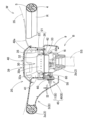
以下、本発明の一実施形態を図面に基づいて説明すると、実施形態のステアリングホイールWは、図1,2,4に示すように、操舵時に把持する操舵部としてのリング部R、リング部Rの中央に配置されるボス部B、及び、リング部Rとボス部Bとを連結するスポーク部S(L,R,B)、を有したステアリングホイールWの本体(ステアリングホイール本体)1と、ボス部Bの上部に配設されるエアバッグ装置20と、を備えて構成される。
Hereinafter, one embodiment of the present invention will be described based on the drawings. As shown in FIGS. A main body (steering wheel main body) 1 of a steering wheel W having a boss part B disposed at the center of the steering wheel W, and spoke parts S (L, R, B) connecting the ring part R and the boss part B; An
なお、本明細書での上下・左右・前後の方向は、ステアリングホイールWを車両のステアリングシャフトSS(図2参照)にナットN止めして接続させた状態における車両の直進操舵時を基準として、上下方向は、そのステアリングシャフトSSの軸方向に沿った上下方向に対応し、左右方向は、そのステアリングシャフトSSの軸直交方向の車両の左右方向に対応し、前後方向は、そのステアリングシャフトSSの軸直交方向の車両の前後方向に対応している。 Note that the directions of up and down, left and right, and front and rear in this specification are based on when the vehicle is steered in a straight line with the steering wheel W connected to the steering shaft SS of the vehicle (see FIG. 2) with a nut N. The vertical direction corresponds to the vertical direction along the axial direction of the steering shaft SS, the left-right direction corresponds to the left-right direction of the vehicle in the direction perpendicular to the axis of the steering shaft SS, and the longitudinal direction corresponds to the vertical direction along the axial direction of the steering shaft SS. It corresponds to the longitudinal direction of the vehicle in the direction perpendicular to the axis.
ステアリングホイール本体1は、リング部R、ボス部B、及び、スポーク部S(L,R,B)を相互に連結するように配設される芯金2と、リング部Rとリング部R近傍のスポーク部Sの芯金2の部位を覆うウレタン等からなる被覆層4と、を備えて構成されている。被覆層4の表面には、皮革5が巻き付けられている。さらに、リング部Rの後部の内周側には、加飾ガーニッシュ7が配設されている。また、ステアリングホイール本体1は、ボス部Bの下面側に、ロアカバー9を配設させて構成されている(図2参照)。
The steering wheel
芯金2は、リング部Rに配置されるリング芯金部2a、ボス部Bに配置されてステアリングシャフトSSと接続されるボス芯金部2b、及び、各スポーク部S(L,R,B)に配置されてリング芯金部2aとボス芯金部2bとを連結するスポーク芯金部2c,2dから構成される。スポーク芯金部2cは、前側の左右二本のスポーク部SL,SRの部位に配設され、スポーク芯金部2dは、後側のスポーク部SBに、左右に分岐して2本配設されている。ボス部Bの上方には、エアバッグカバー39の周囲を囲うように、ベゼル8が配設されている。
The
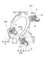
そして、芯金2のボス芯金部2bの周縁には、エアバッグ装置20をステアリングホイール本体1側に組み付ける組付部位11(L,R,B)が、配設されている(図2~4参照)。組付部位11L,11R,11Bは、ボス芯金部2bの左右と後側の三箇所に配設され、それぞれ、略長方形状に開口する組付孔12と、ボス芯金部2bの下面側に配置されて、後述するホーンスイッチ機構45の各組付脚部49(L,R,B)を係止する係止ばね14と、を配設させている。各係止ばね14は、鋼等の導電性を有した棒状のばね材から形成されて、組付孔12の下面側の周縁の取付座13に取り付けられている。そして、各取付座13に取り付けられた係止ばね14は、組付孔12を横断するように配設されるとともに、組付脚部49の挿入時に組付孔12の周縁側に移動するように変形し、かつ、復元して、組付脚部49を係止する係止軸部15を備えている(図17参照)。実施形態の場合、係止軸部15は、ホーン作動回路の負極側となる芯金2側のボス芯金部2bと導通しており、ホーンスイッチ機構45におけるスイッチ部46(L,R,B)の固定側接点48側を構成している(図4参照)。換言すれば、係止軸部15は、エアバッグ装置20を係止する組付部位11を構成するとともに、ホーンスイッチ機構45の各スイッチ部46(L,R,B)における下部46b側の固定側接点48を構成している。なお、固定側接点48の上方には、各スイッチ部46の上部46a側となる後述の可動側接点47が配設される(図5,18参照)。
An assembly portion 11 (L, R, B) for assembling the
エアバッグ装置20は、図1~3,5,6に示すように、膨張用ガスを流入させて膨らむエアバッグ35と(図1,2の二点鎖線参照)、エアバッグ35に膨張用ガスを供給するインフレーター30と、折り畳まれたエアバッグ35を覆ってボス部Bの上面側に配置される合成樹脂製のエアバッグカバー39と、エアバッグ35、インフレーター30、及び、エアバッグカバー39を保持する板金製の取付ベース21と、板金製のリテーナ32と、を備えて構成され、そして、下部側に、ホーンスイッチ機構45の各組付脚部49(L,R,B)を配設させている。
As shown in FIGS. 1 to 3, 5, and 6, the
なお、ホーンスイッチ機構45は、実施形態の場合、ステアリングホイール本体1側の組付孔12と係止ばね14とを配設させた組付部位11(L,R,B)と、各組付部位11(L,R,B)に組み付けられる組付脚部49(L,R,B)と、から構成され、各組付脚部49が、ホーン作動回路の正極側に導通する板金製の脚本体50、脚本体50に組み付けられる絶縁性を有した合成樹脂製のホルダ60、及び、脚本体50を上方へ付勢するように、ホルダ60に保持される金属製の板ばねからなるばね部材80と、から構成されている。そして、ホーンスイッチ機構45は、相互の接触時にホーンを作動させることとなる可動側接点47と固定側接点48とを有してなるスイッチ部46(L,R,B)、を備えて構成され(図4,5参照)、各ばね部材80が可動側接点47を配置させ、各係止ばね14が、ホーン作動回路の負極側となる芯金2と導通して、固定側接点48を配置させる構成としている(図18参照)。
In addition, in the case of the embodiment, the
エアバッグ装置20のエアバッグ35は、球状に近似した厚みのある略円板状の膨張完了形状として(図1,2の二点鎖線参照)、下部側に膨張用ガスを流入するために円形に開口した流入用開口36を備え(図3参照)、流入用開口36の周縁37には、リテーナ32の固着手段としてのボルト32bを貫通させる貫通孔37a(図6参照)が4個形成されている。
The
インフレーター30は、上部に膨張用ガスを吐出させる複数のガス吐出口30bを設けた円柱状の本体部30aを備え、本体部30aの外周面には、四角環状のフランジ部30c(図6参照)が突設されている。フランジ部30cには、リテーナ32のボルト32bを貫通させる貫通孔30dが形成されている。
The inflator 30 includes a cylindrical
リテーナ32は、四角環状の板金製の本体32aを備え、四隅に、下方に突出するボルト32b(図5,6参照)を突設させている。リテーナ32は、エアバッグ35内の流入用開口36の周縁37に配設され、各ボルト32bを、エアバッグ35の貫通孔37a、取付ベース21の貫通孔23b,26b、インフレーター30のフランジ部30cの貫通孔30d、に順に貫通させ、各ボルト32bにナット33を締結させることにより、取付ベース21に、エアバッグ35とインフレーター30とを取り付けている(図3参照)。
The
エアバッグカバー39は、図1,2,5,6に示すように、オレフィン系熱可塑性エラストマー等の合成樹脂製として、ステアリングホイールWの中央付近のボス部Bの上面側に配設されている。エアバッグカバー39は、ボス部Bの内部に折り畳まれて収納されたエアバッグ35の上方を覆う天井壁部40と、天井壁部40の下面から略円筒状に延び、折り畳まれたエアバッグ35の前後左右の側方(外周側)を覆う側壁部41と、を備えて構成されている。
As shown in FIGS. 1, 2, 5, and 6, the
天井壁部40には、膨張するエアバッグ35に押されて前方側に開くドア部40aが、配設されている(図1,2の二点鎖線参照)。ドア部40aは、周囲の薄肉の破断予定部を破断させて開く構成としている。
A
エアバッグカバー39の側壁部41は、図5,6に示すように、下端に、6本の係止脚部42を、配設させている。各係止脚部42は、取付ベース21のアッパプレート22に設けられた係止孔23cに挿入されて、係止孔23cの周縁に係止される。そして、側壁部41の下端面が、取付ベース21のアッパプレート22の上面に当接した状態で、各係止脚部42の係止頭部42aによる係止孔23cの周縁への係止によって、エアバッグカバー39が、取付ベース21に対して、上下にずれたり、あるいは、前後左右にずれたりせずに、取り付けられる。
As shown in FIGS. 5 and 6, the
取付ベース21は、実施形態の場合、図3,5~8に示すように、共に板金製としたアッパプレート22とロアプレート26との2枚から構成されている。取付ベース21のアッパプレート22とロアプレート26とは、エアバッグ35、インフレーター30、及び、エアバッグカバー39、を保持可能に、インフレーター30の本体部30aを挿入可能な挿入孔23a,26aと、リテーナ32の各ボルト32bを貫通可能な貫通孔23b,26bと、を備えて構成されている。
In the case of the embodiment, the mounting
そして、アッパプレート22は、挿入孔23aや貫通孔23bを備える環状部23に、エアバッグカバー39の各係止脚部42を係止する係止孔23cを配設させるとともに、環状部23の外周縁に、エアバッグカバー39の側壁部41の外周面側を覆う側壁部24を配設させて構成されている(図6,7参照)。
In the
ロアプレート26は、図6,8に示すように、ロアプレート26を板金素材からプレス加工する際に、その板金素材の外周縁側に設けた切り起こし部28(L,R,B)を配設している。各切り起こし部28は、挿入孔26aや貫通孔26bの配設された平面状の取付座27から下方に延びるように形成され、実施形態の場合、ホーンスイッチ機構45の各組付脚部49(L,R,B)の脚本体50を形成している。なお、取付座27は、アッパプレート22の環状部23とともに、リテーナ32のボルト32bを貫通させて、各ボルト32bにナット33を締結させれば、エアバッグ35の流入用開口36の周縁37やインフレーター30のフランジ部30cを取り付ける部位となる。
As shown in FIGS. 6 and 8, the
ホーンスイッチ機構45の各組付脚部49(L,R,B)は、図2,3,5,6,9,10に示すように、ステアリングホイール本体1の各組付部位11(L,R,B)に対応する位置に配置されて、それぞれ、既述したように、取付ベース21のロアプレート26から下方に延びるように配設されて、正極側に導通する金属製の脚本体50と、脚本体50の先端側に組み付けられる絶縁性を有したポリプロピレン等からなる合成樹脂製のホルダ60と、脚本体50を上方へ付勢するように、ホルダ60に保持される金属製の板ばねからなるばね部材80と、を備えて構成されている。
Each assembly leg part 49 (L, R, B) of the
各脚本体50は、図3,9,10,15,16に示すように、それぞれ、既述したように、取付ベース21における板金製のロアプレート26の板金素材をプレス加工して、ロアプレート26の取付座27を形成する際、同時に、下方に突出するように、切り起こされて形成された切り起こし部28(L,R,B)、から形成されている。脚本体50は、上下方向に長い略長方形板状として、ボス部Bの中心側(インフレーター30側)の細幅側面51a、外側の細幅側面51b、及び、細幅側面51a,51b相互を連結する広幅側面51c,51cを備えてなる外周面51を設けて構成されている。脚本体50の先端部53は、細幅側面51aに先細りのテーパ面53aを備え、テーパ面53aの上側の細幅側面51aの部位には、長方形状の開口を設けて細幅側面51b側に凹む凹部55が、形成されている。
As shown in FIGS. 3, 9, 10, 15, and 16, each
凹部55の内周側の上側の面は、ばね部材80の後述する当接支持部86に当接して支持されるばね受け座56としている(図9参照)。また、凹部55の内周側の下側の面は、ホルダ60の後述する規制部64の下面側の規制面64bに当接して、ホルダ60における脚本体50からの下方への抜け(外れ)を規制する係止部57としている(図17参照)。なお、係止部57は、ホルダ60が組付部位11の取付固定されれば、規制部64の規制面64bに当接して、ホルダ60に対する脚本体50の上方移動、すなわち、脚本体50における組付部位11からの上方への抜け、が規制されることとなる。
The upper surface of the inner circumferential side of the
ホルダ60は、それぞれ、図3,5,9,10,12~18に示すように、挿入軸部61、係止溝69、鍔部72、及び、ばね部材80を保持する保持部75、を備えて構成されている。
The
挿入軸部61は、脚本体50を下方に移動可能に挿通させるスリット状の挿通孔74を有し、かつ、挿入後の脚本体50の上方への抜けを規制する規制部64を有して、組付部位11の組付孔12に挿入される。挿入軸部61の下端61b側となる先端部67は、組付孔12への挿入時、係止ばね14の係止軸部15に当接して係止軸部15を組付孔12の周縁側に移動させるように、先細り状のテーパ面67aを配設させている。
The
挿入軸部61の下端61b側のテーパ面67aの上方には、組付後の組付部位11からの離脱を規制されるように、係止ばね14の係止軸部15に係止される係止溝69が形成されている。係止溝69は、その内周面の下側の面を、係止軸部15を係止する係止面70としている。
Above the tapered
挿入軸部61の上端61a側の鍔部72は、組付部位11における係止ばね14の係止軸部15に係止面70が係止される際、組付部位11の組付孔12の周縁の上面11a側に当接して、ホルダ60における組付部位11への挿入方向への移動を規制することとなる(図17参照)。そのため、ホルダ60は、係止ばね14の係止軸部15に係止溝69の係止面70が係止されると、鍔部72が、組付孔12の周縁の上面11a側に当接することとなって、上下移動を規制されて、組付部位11に対して取付固定されることとなる。また、鍔部72の下面には、組付孔12の上縁側に嵌合する略四角柱状の嵌合部72aが、形成されている。
The
また、実施形態の場合、挿入軸部61は、挿通孔74を間にして、すなわち、脚本体50の厚さ寸法tより若干広い略同等の隙間hを空けて、鍔部72の下面から相互に平行に突設される二枚の板状部62,63から構成されている。板状部62,63は、外形形状を同等として、テーパ面67aと、係止面70を有した係止溝69と、を備えている。そして、板状部63における板状部62との対向面側に、挿通孔74への挿入後の脚本体50の上方への抜けを規制する規制部64が、配設されている。規制部64は、三角柱状として、下面側の規制面64bが脚本体50の凹部55における下縁側の係止部57を係止する。規制部64は、上面側を、下方側を板状部62側に接近するように傾斜した案内面64aとして、脚本体50の挿通孔74への挿入時、脚本体50の先端部53側が規制部64を乗り越え易いように、構成されている。
Further, in the case of the embodiment, the
また、板状部62,63の係止溝69と反対側の縁相互が、連結板部65により、連結されている。そのため、挿入軸部61の脚本体50が挿入される挿通孔74は、その周壁が、挿通孔74の周縁の鍔部72、板状部62,63、及び、連結板部65から形成されることとなる。そして、脚本体50が、挿通孔74に挿入される際には、外周面51が、挿通孔74の周縁の鍔部72、板状部62,63、及び、連結板部65に位置規制されて、板状部62,63と重なるように、挿入され、そして、規制部64による係止部57の位置規制により、脚本体50のホルダ60からの上方への抜け、すなわち、ホルダ60の脚本体50からの落下、が防止されることとなる。
Further, the edges of the plate-
ホルダ60のばね部材80を保持する保持部75は、連結板部65の上方側に配設されて、板状部62,63における連結板部65の配設されていない凹んだような凹部76と、凹部76から連通して、挿通孔74の上端側を外縁側に広げるように開口される差込口77と、差込口77の外縁側に配設される係止杆部78と、を備えて構成されている。
The holding
ばね部材80は、図9~11,15,16~18に示すように、ホルダ60の保持部75に保持される被保持部81と、脚本体50のばね受け座56に当接させて脚本体50を上方へ付勢するように支持する当接支持部86と、可動側接点47を形成する接点部88と、を備えて構成されている。
As shown in FIGS. 9 to 11, 15, and 16 to 18, the
被保持部81は、ホルダ60の保持部75における係止杆部78に、上方から嵌め込んで組み付ける断面逆U字状の引掛け爪部84を、上下方向に沿って延びる縦杆部83の上端に、配設させて構成されている。縦杆部83は、ホルダ60の差込口77を下方から上方に挿通させるように配設されるとともに、縦杆部83の下端で、横方向(板状部62,63の対向方向に沿う方向)の両側に延びる横杆部82と連結されている。横杆部82は、下縁82aがホルダ60の連結板部65の上端面65aに支持され、そして、縦杆部83が、ホルダ60の凹部76に収納される状態として、横杆部82から上方へ延びるように配設される。すなわち、ばね部材80の被保持部81は、ホルダ60の保持部75への組付時、縦杆部83の上端側の引掛け爪部84がホルダ60の保持部75の係止杆部78に上方から嵌合し、縦杆部83の下端側の横杆部82の下縁82a側がホルダ60の保持部75における凹部76の下面側の連結板部65の上端面65aに位置規制されて、横杆部82から引掛け爪部84にわたる被保持部81が、ホルダ60の凹部76内に嵌合されて、接点部88の下方へのずれや前後左右(板状部62,63の対向方向に沿う方向やその対向方向と直交する方向、換言すれば、上方から見た被保持部81と当接支持部86との対向方向やその対向方向と直交する方向)のずれを規制して、ホルダ60の保持部75に組み付けられることとなる。
The held
接点部88は、横杆部82の両端から斜め上方に延びるように配設され、先端相互を連結するように、当接支持部86と連結されている。そして、接点部88,88が、被保持部81と当接支持部86との間で、ホルダ60における係止溝69の凹部69aの側方で、係止溝69に係止された係止軸部15の上面側に押下操作時に接触可能に、係止軸部15の上方に配置されて、可動側接点47を形成することとなる(図17,18参照)。
The
実施形態の場合、ばね部材80は、中央に、脚本体50と挿入軸部61とを挿通可能な開口80aを設けた四角環の環状体として形成されている。そして、開口80aの周縁の点対称的な位置の一方側に、被保持部81を配設させて、他方側に当接支持部86を配設させて、被保持部81と当接支持部86との間の開口80aの両側を、接点部88,88としている。
In the case of the embodiment, the
なお、ばね部材80は、上方から見た外形寸法を、引掛け爪部84の先端を除いて、組付孔12の開口形状より小さくしており、また、引掛け爪部84は、ホルダ60の鍔部72に囲まれて配置されることから、組付脚部49の組付孔12への組付時、ステアリングホイール本体1の芯金2(ボス芯金部2b)側と接触することはなく、ホーン作動回路の負極側に導通しない。同様に、脚本体50も、ホルダ60に覆われることから、ステアリングホイール本体1の芯金2(ボス芯金部2b)側と導通することはない。また、脚本体50は、凹部55がホルダ60の係止溝69の凹部69aより大きな形状として、係止ばね14の係止軸部15と、直接、接触する構成でない。そのため、脚本体50が、ホーン作動回路の正極側に導通していても、ばね受け座56で当接するばね部材80の当接支持部86を介して、接点部88の可動側接点47が、固定側接点48を構成する係止軸部15に接触しなければ、ホーン作動回路は導通(閉成)しない。
Note that the external dimensions of the
実施形態の各組付脚部49(L,R,B)の組付は、まず、ホルダ60にばね部材80を組み付ける。その作業は、ばね部材80の開口80a内に、ホルダ60の挿入軸部61を上方から挿入させるとともに、ばね部材80の被保持部81の引掛け爪部84を、下方から、差込口77に差し込み、ついで、上方から係止杆部78に嵌め込んで、引掛け爪部84を係止杆部78に係止させるとともに、横杆部82をホルダ60の凹部76における連結板部65の上端面65a側に嵌め込めば、被保持部81が、ホルダ60の保持部75に保持される。ついで、ホルダ60の挿通孔74に、上方から脚本体50を挿入させて、ホルダ60の規制部64に係止部57を係止させる。この組付時、ばね部材80の当接支持部86が、脚本体50のばね受け座56に当接する。そのため、ホルダ60は、係止部57に規制部64に係止されることから、脚本体50に対する落下方向への下方へのずれが規制される。また、ホルダ60における脚本体50に対する上方へのずれは、ホルダ60に被保持部81を保持させたばね部材80の当接支持部86が脚本体50のばね受け座56に当接していることから、ばね部材80の付勢力により、規制されることとなる。すなわち、ホルダ60は、脚本体50に対し、下方に落下することなく、また、ばね部材80の付勢力により、大きく上方へずれることなく、組み付けられる状態となる。
To assemble each assembly leg portion 49 (L, R, B) of the embodiment, first, the
また、実施形態のエアバッグ装置20の組み立ては、まず、各ボルト32bを貫通孔37aから突出させた状態で、エアバッグ35の内部にリテーナ32を入れて、エアバッグ35を折り畳み、折り崩れ防止用の図示しないラッピング材で包む。ついで、挿入孔23a,26a相互や貫通孔23b,30d相互を一致させて、アッパプレート22の下方に、ホーンスイッチ機構45の各組付脚部49を組み付けたロアプレート26を配置させ、その後、アッパプレート22の環状部23の上に、エアバッグ35の流入用開口36の周縁37を配置させて、リテーナ32の各ボルト32bを、アッパプレート22やロアプレート26の貫通孔23b,30dに貫通させ、さらに、インフレーター30の本体部30aを、アッパプレート22やロアプレート26の挿入孔22a,26aを経て、エアバッグ35内に挿入させつつ、アッパプレート22やロアプレート26の貫通孔23b,30dから突出しているリテーナ32の各ボルト32bを、インフレーター30の貫通孔30dに貫通させ、そして、各ボルト32bにナット33を締結すれば、アッパプレート22とロアプレート26とを結合させて取付ベース21を形成できるとともに、取付ベース21に、エアバッグ35とインフレーター30とを取り付けることができる。その後、エアバッグカバー39をエアバッグ35に被せて、側壁部41の下端の各係止脚部42を取付ベース21の係止孔23cに挿入させて係止させれば、エアバッグカバー39が取付ベース21に結合されて、エアバッグ装置20の組立が完了する。
The
エアバッグ装置20の車両への搭載は、ステアリングシャフトSSへ組付済みのステアリングホイール本体1の各組付部位11の組付孔12に、図17のA,Bに示すように、各ホーンスイッチ機構45の組付脚部49を挿入させて、各係止ばね14の係止軸部15を組付孔12の周縁側に移動するように変形させ、かつ、復元させて、組付脚部49の係止溝69に係止させれば、エアバッグ装置20をステアリングホイール本体1に組み付けることができ、ステアリングホイールWの組立が完了するとともに、ステアリングホイールWを、エアバッグ装置20とともに、車両に搭載することができる。
The
なお、エアバッグ装置20のステアリングホイール本体1への組付時(取付時)には、ロアプレート26の図示しないリード線を、ホーン作動回路の正極側に結線し、また、インフレーター30に、作動信号入力用の図示しないリード線を結線することとなる。
Note that when assembling (installing) the
車両への搭載後、インフレーター30に作動信号が入力されれば、インフレーター30は、膨張用ガスをガス吐出口30bから吐出させることから、折り畳まれたエアバッグ35は、膨張用ガスを流入させて膨張し、エアバッグカバー39の天井壁部40のドア部40aを押し開き、ドア部40aの開いた開口から突出して、ボス部Bの上方からリング部Rの上面を覆うように、展開膨張することととなる(図1,2の二点鎖線参照)。
When an activation signal is input to the inflator 30 after being installed in a vehicle, the inflator 30 discharges inflation gas from the
また、インフレーター30の非作動時における通常使用時において、ホーンスイッチ機構45を操作するように、エアバッグ装置20のエアバッグカバー39を押下すれば、図18のA,Bに示すように、取付ベース21のロアプレート26の下面側から下方に延びる脚本体50のばね受け座56が、組付部位11に組み付けられたホルダ60に対して保持されているばね部材80の付勢力に抗して、下降し、ばね部材80におけるばね受け座56と当接している当接支持部86と接点部88とを下降させる。接点部88が下降すれば、接点部88が、ホルダ60の係止溝69に係止していたステアリングホイール本体1側の組付部位11のばね部材14における係止軸部15に接近し、そして、ばね部材80の接点部88の可動側接点47が、係止溝69の凹部69a内に配設されていた固定側接点48を構成する係止軸部15に当接して、ホーン作動回路が導通することから、ホーンを作動させることとなる。
In addition, during normal use when the inflator 30 is not activated, if the
また、ホーンスイッチ機構45を構成するステアリングホイール本体1側の各組付部位11に対応するエアバッグ装置20側が、取付ベース21のロアプレート26から延びる脚本体50と、脚本体50を挿入させて、脚本体50の係止部57を抜けないよう規制する規制部64を有する絶縁性を有したホルダ60と、取付ベース21のロアプレート26側を上方へ付勢するように脚本体50のばね受け座56に当接される当接支持部86を有したばね部材80と、の3部品で構成されている。そして、ホルダ60は、被保持部81を保持部75で保持してばね部材80を組み付けることができ、その組付状態で、さらに、脚本体50を挿通孔74に挿通させ、脚本体50の係止部57の抜けを規制する規制部64を利用して、脚本体50からの抜けを防止されて、脚本体50に組付可能としている。そのため、ばね部材80を組み付けた状態のホルダ60を脚本体50に組み付けることができ、その組付状態では、単に、ホルダ60の挿入軸部61をステアリングホイール本体1の組付部位11の組付孔12に挿入させれば、係止ばね14の係止軸部15を組付孔12の周縁に移動させて復元させることにより、ホルダ60の挿入軸部61の先端側の係止溝69に係止軸部15を係止させることができ、また、ホルダ60の挿入軸部61の上端側の鍔部72を組付部位11における上面11a側の組付孔12の周縁に当接させることとなって、ホルダ60が、組付部位11に対して抜けず、かつ、鍔部72によって、挿入方向(下方)への移動も規制されて、組付部位11に取付固定される。そして、ホルダ60に保持されたばね部材80が、脚本体50を上方に付勢し、また、脚本体50は、係止部57をホルダ60の規制部64に規制されて、ホルダ60からの上方への抜けが規制されることから、押下操作時の操作ストローク(ホーンストローク)HSを維持して、脚本体50を設けた取付ベース21(ロアプレート26)、すなわち、エアバッグ装置20がステアリングホイール本体1に組み付けられることとなる。そのため、ホーンスイッチ機構45を構成する脚本体50に対して、ばね部材80を保持したホルダ60を組み付ければ、ホルダ60と脚本体50とからなる組付脚部49を、単に、ステアリングホイール本体1の組付孔12の挿入させるだけで、簡単に、ホーンスイッチ機構45を介在させて、エアバッグ装置20をステアリングホイール本体1に組み付けることができる。
Further, the
したがって、実施形態のステアリングホイールWは、ホーンスイッチ機構45を、ステアリングホイール本体1の係止ばね14の他、取付ベース21側の脚本体50と、ホルダ60と、ばね部材80と、の三種類の部品で構成できて、ホーンスイッチ機構45の部品点数を低減でき、さらに、ステアリングホイール本体1へのエアバッグ装置20の組付も、簡便に行える。
Therefore, the steering wheel W of the embodiment has three types of horn switch mechanisms 45: the locking
そして、実施形態では、脚本体50が、取付ベース21のロアプレート26を形成する板金素材から切り起こされて、取付ベース21のロアプレート26と一体的に形成されている。
In the embodiment, the
そのため、実施形態では、ホーンスイッチ機構45を構成する脚本体50が、取付ベース21のロアプレート26と一体的に形成されていることから、ホーンスイッチ機構45を構成する部品点数が、ステアリングホイール本体1側の係止ばね14の他、ホルダ60とばね部材80の二種類となって、一層、低減される。
Therefore, in the embodiment, since the
また、実施形態では、ばね部材80が、中央に、脚本体50とホルダ60の挿入軸部61とを挿通可能な開口80aを設けた環状体(四角環状体)として形成されて、開口80aの周縁の点対称的な位置の一方側に、被保持部81を配設させて、他方側に当接支持部86を配設させて、被保持部81と当接支持部86との間の開口80aの両側を、接点部88,88としている。
Further, in the embodiment, the
そのため、実施形態では、1つのばね部材80が、環状体として、形成されており、押下操作時に弾性変形する可動側接点47を設けた両側の接点部88,88が、先端88a側相互を当接支持部86で連結され、元部88b側相互を被保持部81で連結される構成となることから、ホーン操作時の押下操作を長期間に亘って行っても、係止軸部15に沿ってずれる変形を抑制されて、ホーン操作時のばね部材80の耐久性を向上させることができる。また、ばね部材80の当接支持部86が、両端を二本の接点部88に連結支持される状態として、脚本体50を上方へ付勢することから、二本分の接点部88の反発力により、十分な付勢力を確保できて、エアバッグ装置20が重くとも、円滑に、脚本体50を上方へ付勢して、所定のホーンストロークHS、すなわち、可動側接点47の固定側接点48からの上方への離隔距離、を確保できる。
Therefore, in the embodiment, one
なお、実施形態の場合、取付ベース21は、アッパプレート22とロアプレート26との2枚構成としているが、ロアプレート26に、エアバッグカバー39の係止脚部42を係止する係止孔23cを設ければ、ロアプレート26の一枚から取付ベース21を構成してもよい。すなわち、その場合には、ロアプレート26だけで、エアバッグ35、インフレーター30、及び、エアバッグカバー39を保持する取付ベース21を構成できて、本発明において、一枚構成の取付ベースとしてもよい。
In the case of the embodiment, the mounting
また、実施形態では、ホーンスイッチ機構45の組付部位11(L,R,B)と組付脚部49(L,R,B)とを相互に対応させて、三箇所に配設したが、相互に対応させれば、四箇所以上の位置に、組付部位と組付脚部とを配設してもよい。
Further, in the embodiment, the assembly portion 11 (L, R, B) of the
さらに、実施形態の場合、取付ベース21のロアプレート26を切り起こして形成した長方形板状の脚本体50を、四角環状のばね部材80を保持したホルダ60の挿通孔74に挿入させて、ホルダ60を脚本体50に組み付けて、ホーンスイッチ機構45の組付脚部49を形成する構成とし、さらに、可動側接点47に対応する固定側接点48自体を、組付脚部49を組み付ける組付部位11の係止ばね14の係止軸部15から構成して、インフレーター30の下方側で、インフレーター30に接近させて、スイッチ部46を配設することができる。そのため、従来の円柱状のホーンスイッチ体を、インフレーター30の下方側に配設する場合には、インフレーター30を保持する取付ベースに、凹むような絞り加工を施して、ホーンスイッチ体の組付座を設けることとなってしまい、その場合には、組付座が絞り加工による逆円錐台形となって、取付ベースの組付座を含めた外形寸法が大きくなっていた。これに対し、本発明では、そのような絞り加工の組付座が不要となることから、取付ベースの外形寸法を小さくできて、エアバッグ装置20の外形寸法を小さくでき、エアバッグ装置20の小型化に寄与できることとなる。
Furthermore, in the case of the embodiment, a rectangular plate-shaped
1…ステアリングホイール本体、11(L,R,B)…組付部位、11a…(組付孔周縁の)上面、12…組付孔、14…係止ばね、15…(固定側接点)係止軸部、20…エアバッグ装置、21…取付ベース、26…ロアプレート、28(L,R,B)…(脚本体)切り起こし部、30…インフレーター、35…エアバッグ、39…エアバッグカバー、45…ホーンスイッチ機構、46(L,R,B)…スイッチ部、47…可動側接点、48…固定側接点、49(L,R,B)…組付脚部、50…脚本体、53…先端部、55…凹部、56…ばね受け座、57…係止部、60…ホルダ、61…挿入軸部、64…規制部、67…先端部、69…係止溝、69a…凹部、70…係止面、72…鍔部、74…挿通孔、75…保持部、80…ばね部材、80a…開口、81…被保持部、86…当接支持部、88…接点部、
R…(操舵部)リング部、B…ボス部、W…ステアリングホイール。
DESCRIPTION OF
R... (steering section) ring section, B... boss section, W... steering wheel.
Claims (3)
該エアバッグ装置を、運転者が操舵する操舵部の中央付近の上部側に搭載するステアリングホイール本体と、
を備えて構成され、
前記エアバッグ装置の下面側の少なくとも三箇所に設けられた組付脚部を、前記ステアリングホイール本体に配設された組付部位に挿入させ、該組付部位に配設された係止ばねに係止させて、前記エアバッグ装置が前記ステアリングホイール本体に組み付けられるとともに、
前記エアバッグ装置の押下操作により、ホーン作動回路の一方の正極側に導通する前記エアバッグ装置側の可動側接点を、他方の負極側に導通する前記ステアリングホイール本体側の固定側接点に、接触させて、ホーンを作動可能なホーンスイッチ機構を配設させて構成されるステアリングホイールであって、
前記組付部位が、それぞれ、
前記組付脚部を挿入させる組付孔と、
該組付孔の下面側の周縁に前記組付孔を横断するように配設されるとともに、前記組付脚部の挿入時に前記組付孔の周縁側に移動するように変形し、かつ、復元して、前記組付脚部を係止可能な係止軸部を配設させた係止ばねと、
を配設させて構成されるとともに、
前記係止ばねの前記係止軸部が、前記固定側接点を形成する構成とし、
前記組付脚部が、それぞれ、
前記取付ベースから下方に延びるように配設されて、正極側に導通する金属製の脚本体と、
該脚本体の先端側に組み付けられる絶縁性を有した合成樹脂製のホルダと、
前記脚本体を上方へ付勢するように、前記ホルダに保持される金属製の板ばねからなるばね部材と、
を備えて構成され、
前記ホルダが、
前記脚本体を下方に移動可能に挿通させる挿通孔を有し、かつ、挿入後の前記脚本体の上方への抜けを規制する規制部を有して、前記組付孔に挿入される挿入軸部と、
該挿入軸部の下端側に配置されて、組付後の前記組付部位からの離脱を規制されるように、前記係止ばねの係止軸部に係止される係止溝と、
前記挿入軸部の上端側に配置されて、前記組付部位の上面側の前記組付孔の周縁に当設して、前記組付部位への挿入方向への移動を規制する鍔部と、
前記ばね部材を保持する保持部と、
を備え、
前記ばね部材が、
前記ホルダの前記保持部に保持される被保持部と、
前記脚本体に当接させて前記脚本体を上方へ付勢するように支持する当接支持部と、
前記被保持部と前記当接支持部との間で、前記ホルダにおける前記係止溝の凹部の側方で、前記係止溝に係止された前記係止軸部の上面側に押下操作時に接触可能に、前記係止軸部の上方に配置されて前記可動側接点を形成する接点部と、
を備えて構成され、
前記脚本体が、
前記ホルダの前記挿通孔に挿入された状態での押下操作時に、前記当接支持部と前記接点部とを下方移動させて、前記可動側接点を前記固定側接点に当接可能に、前記ばね部材の前記当接支持部と当接する当接面を下面側に配置させたばね受け座と、
前記ホルダの前記規制部に当接して、前記ホルダからの上方への抜けを規制される係止部と、
を備えて構成されていることを特徴とするステアリングホイール。 an airbag, an inflator that supplies inflation gas to the airbag, an airbag cover that covers the folded airbag, and a mounting base that holds the airbag, the inflator, and the airbag cover; An airbag device comprising:
a steering wheel body in which the airbag device is mounted on an upper side near the center of a steering section steered by a driver;
configured with
The assembly legs provided at at least three locations on the lower surface side of the airbag device are inserted into the assembly site provided on the steering wheel body, and the locking springs provided at the assembly site are inserted into the assembly leg portions provided at least three locations on the lower surface side of the airbag device. The airbag device is assembled to the steering wheel body by being locked, and
When the airbag device is pressed down, a movable contact on the airbag device that is electrically connected to one positive electrode of the horn operating circuit is brought into contact with a fixed contact on the steering wheel body that is electrically conductive to the other negative electrode. A steering wheel configured by disposing a horn switch mechanism capable of operating a horn,
The assembly parts are each
an assembly hole into which the assembly leg is inserted;
disposed on the periphery of the lower surface of the assembly hole so as to cross the assembly hole, and deformed so as to move toward the periphery of the assembly hole when the assembly leg is inserted; a locking spring that is restored and has a locking shaft portion that can lock the assembly leg portion;
In addition to being configured by arranging
The locking shaft portion of the locking spring forms the fixed side contact,
The assembly leg portions each include:
a metal script body arranged to extend downward from the mounting base and conductive to the positive electrode side;
a holder made of insulating synthetic resin that is assembled on the tip side of the script body;
a spring member made of a metal leaf spring held by the holder so as to bias the script body upward;
configured with
The holder is
an insertion shaft inserted into the assembly hole, having an insertion hole through which the script body is inserted so as to be movable downward; and a regulating portion that restricts the script body from coming off upward after insertion; Department and
a locking groove that is disposed on the lower end side of the insertion shaft and is locked to the locking shaft of the locking spring so as to restrict separation from the assembly site after assembly;
a flange portion that is disposed on the upper end side of the insertion shaft portion, abuts against the periphery of the assembly hole on the upper surface side of the assembly portion, and restricts movement in the insertion direction into the assembly portion;
a holding part that holds the spring member;
Equipped with
The spring member is
a held part held by the holding part of the holder;
an abutting support part that abuts the script body and supports the script body so as to bias the script body upward;
Between the held part and the abutting support part, on the side of the concave part of the locking groove in the holder, when pressing down on the upper surface side of the locking shaft part locked in the locking groove. a contact part that is contactably disposed above the locking shaft part and forms the movable contact;
configured with
The script font is
When the holder is inserted into the insertion hole and is pressed down, the contact support portion and the contact portion are moved downward so that the movable contact can come into contact with the fixed contact. a spring receiving seat in which a contact surface that contacts the contact support portion of the member is arranged on the lower surface side;
a locking portion that comes into contact with the restriction portion of the holder and is restricted from coming off upward from the holder;
A steering wheel comprising:
前記取付ベースを形成する板金素材から切り起こされて、前記取付ベースと一体的に形成されていることを特徴とする請求項1に記載のステアリングホイール。 The script font is
The steering wheel according to claim 1, wherein the steering wheel is cut and raised from a sheet metal material forming the mounting base and is formed integrally with the mounting base.
前記開口の周縁の点対称的な位置の一方側に、前記被保持部を配設させて、他方側に前記当接支持部を配設させて、前記被保持部と前記当接支持部との間の前記開口の両側を、前記接点部としていることを特徴とする請求項1若しくは請求項2に記載のステアリングホイール。 The spring member is formed as an annular body having an opening in the center through which the script body and the insertion shaft portion of the holder can be inserted,
The held part is disposed on one side of a point-symmetrical position on the periphery of the opening, and the abutment support part is disposed on the other side, so that the held part and the abutment support part are arranged. The steering wheel according to claim 1 or 2, wherein both sides of the opening between the two are used as the contact portions.
Priority Applications (1)
| Application Number | Priority Date | Filing Date | Title |
|---|---|---|---|
| JP2021058401A JP7363849B2 (en) | 2021-03-30 | 2021-03-30 | steering wheel |
Applications Claiming Priority (1)
| Application Number | Priority Date | Filing Date | Title |
|---|---|---|---|
| JP2021058401A JP7363849B2 (en) | 2021-03-30 | 2021-03-30 | steering wheel |
Publications (2)
| Publication Number | Publication Date |
|---|---|
| JP2022155069A JP2022155069A (en) | 2022-10-13 |
| JP7363849B2 true JP7363849B2 (en) | 2023-10-18 |
Family
ID=83556982
Family Applications (1)
| Application Number | Title | Priority Date | Filing Date |
|---|---|---|---|
| JP2021058401A Active JP7363849B2 (en) | 2021-03-30 | 2021-03-30 | steering wheel |
Country Status (1)
| Country | Link |
|---|---|
| JP (1) | JP7363849B2 (en) |
Citations (4)
| Publication number | Priority date | Publication date | Assignee | Title |
|---|---|---|---|---|
| US20020043786A1 (en) | 2000-10-12 | 2002-04-18 | Trw Automotive Safety Systems Gmbh & Co. Kg | Vehicle steering wheel |
| US20110204602A1 (en) | 2010-02-23 | 2011-08-25 | Judco Manufacturing, Inc. | Airbag frame apparatus |
| JP2013209009A (en) | 2012-03-30 | 2013-10-10 | Toyoda Gosei Co Ltd | Steering wheel including airbag device |
| JP2014015185A (en) | 2012-07-11 | 2014-01-30 | Suzuki Motor Corp | Steering wheel with airbag system |
-
2021
- 2021-03-30 JP JP2021058401A patent/JP7363849B2/en active Active
Patent Citations (4)
| Publication number | Priority date | Publication date | Assignee | Title |
|---|---|---|---|---|
| US20020043786A1 (en) | 2000-10-12 | 2002-04-18 | Trw Automotive Safety Systems Gmbh & Co. Kg | Vehicle steering wheel |
| US20110204602A1 (en) | 2010-02-23 | 2011-08-25 | Judco Manufacturing, Inc. | Airbag frame apparatus |
| JP2013209009A (en) | 2012-03-30 | 2013-10-10 | Toyoda Gosei Co Ltd | Steering wheel including airbag device |
| JP2014015185A (en) | 2012-07-11 | 2014-01-30 | Suzuki Motor Corp | Steering wheel with airbag system |
Also Published As
| Publication number | Publication date |
|---|---|
| JP2022155069A (en) | 2022-10-13 |
Similar Documents
| Publication | Publication Date | Title |
|---|---|---|
| US6688637B2 (en) | Airbag apparatus | |
| US7694997B2 (en) | Air bag module | |
| US6995328B2 (en) | Horn switch gear and airbag system | |
| US8342567B2 (en) | Airbag-equipped steering wheel device | |
| US8459686B2 (en) | Steering wheel with airbag device | |
| US20100066066A1 (en) | Steering wheel with airbag device and method for assembling the same | |
| US7268309B2 (en) | Horn switch gear and airbag system | |
| CN110712674B (en) | Steering wheel damper mechanism and vehicle steering wheel device | |
| US20050236820A1 (en) | Steering apparatus | |
| JPH04353072A (en) | Horn switch device of steering wheel | |
| JP5099047B2 (en) | Steering wheel with airbag device and method for determining fastening state of horn switch mechanism | |
| CN114845926A (en) | Steering wheel device for vehicle | |
| US10994684B2 (en) | Airbag device for vehicle | |
| US11338756B2 (en) | Airbag device with horn switch body | |
| JP7363849B2 (en) | steering wheel | |
| US10899302B2 (en) | Airbag device | |
| US20230406252A1 (en) | Steering wheel and method of manufacturing same | |
| JP2010069938A (en) | Steering wheel with airbag device | |
| JP3895896B2 (en) | Airbag module | |
| CN116056968A (en) | Steering wheel device for vehicle | |
| JP2001341651A (en) | Vehicle steering wheel | |
| JP5092296B2 (en) | Steering wheel device and assembly method thereof | |
| JP2006092921A (en) | Horn switch device, air-bag device and steering device | |
| JP2017088115A (en) | Automobile component | |
| JPH08253155A (en) | Steering wheel |
Legal Events
| Date | Code | Title | Description |
|---|---|---|---|
| A621 | Written request for application examination |
Free format text: JAPANESE INTERMEDIATE CODE: A621 Effective date: 20230327 |
|
| A977 | Report on retrieval |
Free format text: JAPANESE INTERMEDIATE CODE: A971007 Effective date: 20230824 |
|
| TRDD | Decision of grant or rejection written | ||
| A01 | Written decision to grant a patent or to grant a registration (utility model) |
Free format text: JAPANESE INTERMEDIATE CODE: A01 Effective date: 20230905 |
|
| A61 | First payment of annual fees (during grant procedure) |
Free format text: JAPANESE INTERMEDIATE CODE: A61 Effective date: 20230918 |
|
| R151 | Written notification of patent or utility model registration |
Ref document number: 7363849 Country of ref document: JP Free format text: JAPANESE INTERMEDIATE CODE: R151 |