JP7363765B2 - Image processing device, imaging device, and image processing method - Google Patents
Image processing device, imaging device, and image processing method Download PDFInfo
- Publication number
- JP7363765B2 JP7363765B2 JP2020504791A JP2020504791A JP7363765B2 JP 7363765 B2 JP7363765 B2 JP 7363765B2 JP 2020504791 A JP2020504791 A JP 2020504791A JP 2020504791 A JP2020504791 A JP 2020504791A JP 7363765 B2 JP7363765 B2 JP 7363765B2
- Authority
- JP
- Japan
- Prior art keywords
- image
- image area
- restored
- roi
- restored image
- Prior art date
- Legal status (The legal status is an assumption and is not a legal conclusion. Google has not performed a legal analysis and makes no representation as to the accuracy of the status listed.)
- Active
Links
- 238000012545 processing Methods 0.000 title claims description 168
- 238000003384 imaging method Methods 0.000 title claims description 54
- 238000003672 processing method Methods 0.000 title claims description 11
- 239000011159 matrix material Substances 0.000 claims description 242
- 238000005070 sampling Methods 0.000 claims description 175
- 238000004364 calculation method Methods 0.000 claims description 86
- 238000000034 method Methods 0.000 claims description 49
- 230000008569 process Effects 0.000 claims description 41
- 230000005855 radiation Effects 0.000 claims description 18
- 230000010287 polarization Effects 0.000 claims description 7
- 238000010586 diagram Methods 0.000 description 30
- 238000001514 detection method Methods 0.000 description 27
- 230000005469 synchrotron radiation Effects 0.000 description 17
- 230000005540 biological transmission Effects 0.000 description 15
- 230000006870 function Effects 0.000 description 14
- 230000035945 sensitivity Effects 0.000 description 6
- 238000004891 communication Methods 0.000 description 5
- 230000000694 effects Effects 0.000 description 5
- 238000004088 simulation Methods 0.000 description 4
- 230000008859 change Effects 0.000 description 3
- 239000000470 constituent Substances 0.000 description 2
- 230000007423 decrease Effects 0.000 description 2
- 230000000670 limiting effect Effects 0.000 description 2
- 230000003287 optical effect Effects 0.000 description 2
- 230000002730 additional effect Effects 0.000 description 1
- 238000006243 chemical reaction Methods 0.000 description 1
- 239000002131 composite material Substances 0.000 description 1
- 238000011161 development Methods 0.000 description 1
- 238000005516 engineering process Methods 0.000 description 1
- 239000000284 extract Substances 0.000 description 1
- 238000005259 measurement Methods 0.000 description 1
- 239000000203 mixture Substances 0.000 description 1
- 230000004044 response Effects 0.000 description 1
- 239000004065 semiconductor Substances 0.000 description 1
Images


Classifications
-
- G—PHYSICS
- G06—COMPUTING; CALCULATING OR COUNTING
- G06T—IMAGE DATA PROCESSING OR GENERATION, IN GENERAL
- G06T5/00—Image enhancement or restoration
- G06T5/50—Image enhancement or restoration by the use of more than one image, e.g. averaging, subtraction
-
- G—PHYSICS
- G02—OPTICS
- G02B—OPTICAL ELEMENTS, SYSTEMS OR APPARATUS
- G02B27/00—Optical systems or apparatus not provided for by any of the groups G02B1/00 - G02B26/00, G02B30/00
- G02B27/58—Optics for apodization or superresolution; Optical synthetic aperture systems
-
- G—PHYSICS
- G02—OPTICS
- G02B—OPTICAL ELEMENTS, SYSTEMS OR APPARATUS
- G02B5/00—Optical elements other than lenses
- G02B5/30—Polarising elements
- G02B5/3025—Polarisers, i.e. arrangements capable of producing a definite output polarisation state from an unpolarised input state
-
- G—PHYSICS
- G06—COMPUTING; CALCULATING OR COUNTING
- G06T—IMAGE DATA PROCESSING OR GENERATION, IN GENERAL
- G06T5/00—Image enhancement or restoration
-
- H—ELECTRICITY
- H04—ELECTRIC COMMUNICATION TECHNIQUE
- H04N—PICTORIAL COMMUNICATION, e.g. TELEVISION
- H04N23/00—Cameras or camera modules comprising electronic image sensors; Control thereof
- H04N23/50—Constructional details
- H04N23/55—Optical parts specially adapted for electronic image sensors; Mounting thereof
-
- H—ELECTRICITY
- H04—ELECTRIC COMMUNICATION TECHNIQUE
- H04N—PICTORIAL COMMUNICATION, e.g. TELEVISION
- H04N23/00—Cameras or camera modules comprising electronic image sensors; Control thereof
- H04N23/60—Control of cameras or camera modules
- H04N23/62—Control of parameters via user interfaces
-
- H—ELECTRICITY
- H04—ELECTRIC COMMUNICATION TECHNIQUE
- H04N—PICTORIAL COMMUNICATION, e.g. TELEVISION
- H04N23/00—Cameras or camera modules comprising electronic image sensors; Control thereof
- H04N23/60—Control of cameras or camera modules
- H04N23/69—Control of means for changing angle of the field of view, e.g. optical zoom objectives or electronic zooming
-
- H—ELECTRICITY
- H04—ELECTRIC COMMUNICATION TECHNIQUE
- H04N—PICTORIAL COMMUNICATION, e.g. TELEVISION
- H04N23/00—Cameras or camera modules comprising electronic image sensors; Control thereof
- H04N23/80—Camera processing pipelines; Components thereof
-
- G—PHYSICS
- G02—OPTICS
- G02B—OPTICAL ELEMENTS, SYSTEMS OR APPARATUS
- G02B2207/00—Coding scheme for general features or characteristics of optical elements and systems of subclass G02B, but not including elements and systems which would be classified in G02B6/00 and subgroups
- G02B2207/129—Coded aperture imaging
-
- G—PHYSICS
- G06—COMPUTING; CALCULATING OR COUNTING
- G06T—IMAGE DATA PROCESSING OR GENERATION, IN GENERAL
- G06T2207/00—Indexing scheme for image analysis or image enhancement
- G06T2207/10—Image acquisition modality
- G06T2207/10052—Images from lightfield camera
Description
本開示は、画像処理装置、および撮像装置、並びに画像処理方法に関する。特に、レンズレスカメラ(レンズレス撮像装置)の撮影画像の画角制御を可能とし、撮影領域の一部からなる復元画像を生成する画像処理装置、および撮像装置、並びに画像処理方法に関する。 The present disclosure relates to an image processing device, an imaging device, and an image processing method. In particular, the present invention relates to an image processing device, an imaging device, and an image processing method that enable control of the angle of view of an image taken by a lensless camera (lensless imaging device) and generate a restored image consisting of a part of the imaging area.
近年、レンズを利用せずに画像を撮影可能としたレンズレスカメラの開発が進んでいる。従来の一般的なカメラは、レンズを介した光を撮像素子である画像センサに入力して画像を撮影するが、レンズレスカメラは、レンズの代わりに光の透過領域と不透過領域を2次元パターンとして設定したマスクを用い、マスクを介した光を画像センサに入力する。画像センサにはマスクを介した像が撮影される。このマスクを介した撮像データに対して、所定の信号処理を行うことで、一般的なカメラと同様の撮影シーンに対応する2次元画像を生成することができる。レンズレスカメラは、レンズが不要であるため、撮像装置の小型化、軽量化が実現される。 In recent years, the development of lensless cameras that can take images without using a lens has progressed. A conventional general camera captures an image by inputting light through a lens to an image sensor, which is an image sensor, but a lensless camera uses a two-dimensional light transmitting area and a non-transmitting area instead of a lens. Using a mask set as a pattern, light passing through the mask is input to the image sensor. The image sensor captures an image through the mask. By performing predetermined signal processing on the image data obtained through this mask, it is possible to generate a two-dimensional image corresponding to the same photographic scene as with a general camera. Since a lensless camera does not require a lens, the imaging device can be made smaller and lighter.
上述したように、レンズレスカメラは、マスクを介した光を画像センサに入力する。シーン(撮影シーン)からの放射光が、マスクを通してどのようにセンサ上に投影されるかの情報を、あらかじめマトリックスとして定義しておき、そのマトリックスとセンサ上に投影された画像(観測画像)から、実際のシーンを再現した画像(復元画像)を生成するものである。 As mentioned above, a lensless camera inputs light through a mask to an image sensor. Information on how the synchrotron radiation from the scene (photographed scene) is projected onto the sensor through the mask is defined in advance as a matrix, and from that matrix and the image projected onto the sensor (observed image) , which generates an image (restored image) that reproduces the actual scene.
なお、レンズレスカメラについては、例えば、以下の文献に記載がある。
特許文献1(国際公開WO2012/040192号公報)。Note that lensless cameras are described, for example, in the following documents.
Patent Document 1 (International Publication WO2012/040192).
レンズレスカメラの画像センサ上に投影された画像(観測画像)から、実際のシーンを再現した画像(復元画像)を生成する撮影画像の再構成処理としては、例えば以下の処理が行われる。撮影シーンの放射光を3次元上の複数のサンプリングポイントの輝度値で表現し、マスクを介して画像センサ上に投影されるセンサ観測値の組を、シミュレーションなどで複数組、予め求める。 For example, the following processing is performed as a photographed image reconstruction process that generates an image (restored image) that reproduces an actual scene from an image (observed image) projected on the image sensor of a lensless camera. The emitted light of the photographed scene is expressed by the luminance values of a plurality of three-dimensional sampling points, and a plurality of sets of sensor observed values to be projected onto the image sensor via a mask are determined in advance by simulation or the like.
さらに、それらの組からマスクを表現するマスクマトリックスを計算する。このマスクマトリックスの逆行列を求め、この逆行列を、観測値、すなわちレンズレスカメラの画像センサの画素値に適用して、撮影シーンを構成するサンプリングポイント毎の輝度値を復元する。サンプリングポイント毎の輝度値は、撮影シーンの画像を示す輝度値となる。 Furthermore, a mask matrix representing the mask is calculated from these sets. The inverse matrix of this mask matrix is obtained, and this inverse matrix is applied to the observed values, that is, the pixel values of the image sensor of the lensless camera, to restore the brightness value for each sampling point that makes up the photographed scene. The brightness value for each sampling point is a brightness value that indicates the image of the photographed scene.
3次元上のP個のサンプリングポイントから放射される光を、長さPのシーン放射光ベクトルxとして表記し、それを受光する画素数Nの2次元センサの観測値を、長さNのシーン観測値ベクトルyとして表現すると、その関係は、
y=Mx
と表す事ができる。ここで、Mはマスクの透過関数を表すマトリックス、すなわちマスクマトリックス(マスク行列)である。The light emitted from P sampling points in three dimensions is expressed as a scene emitted light vector x of length P, and the observed value of a two-dimensional sensor with N pixels that receives the light is expressed as a scene of length N. When expressed as an observed value vector y, the relationship is
y=Mx
It can be expressed as Here, M is a matrix representing the transmission function of the mask, that is, a mask matrix.
シーンの放射光を再現するには、この式の関係を満たすxを、レンズレスカメラのセンサ観測値yから求めれば良い。再現されるシーンの解像度は、シーンを構成する3次元上のサンプリングポイントの数Pを大きくすることで向上させることができる。ただし、シーン放射光ベクトルxを推定する時間が長くなり、画像の再構成に時間を要することになる In order to reproduce the emitted light of the scene, x that satisfies this relationship can be found from the sensor observation value y of the lensless camera. The resolution of the reproduced scene can be improved by increasing the number P of three-dimensional sampling points that make up the scene. However, it takes a long time to estimate the scene radiation vector x, and it takes time to reconstruct the image.
上記式、y=Mxは、レンズレスカメラのセンサに入射する全ての光がセンサ上に重畳されることを示しており、復元される画像の画角(FOV:Field Of View)は、非常に広いものとなる。 The above equation, y=Mx, indicates that all the light incident on the sensor of a lensless camera is superimposed on the sensor, and the field of view (FOV) of the restored image is very large. It becomes wide.
レンズレスカメラの画角(FOV)は広いため、シーン全体を表現するサンプリングポイント数Pが多くなる。しかし、カメラとして使用する場合、ある程度、FOVを狭めて、撮影範囲を限定したいといった場合も多い。撮影画像の一部のみを切り出すことも可能であるが、その場合、解像度が低下してしまうという問題が発生する。 Since the angle of view (FOV) of a lensless camera is wide, the number of sampling points P that represents the entire scene increases. However, when using it as a camera, it is often desirable to narrow the FOV to some extent to limit the photographic range. Although it is possible to cut out only a part of the photographed image, in that case, a problem arises in that the resolution decreases.
また、上述したように、撮影画像として再現可能な3次元上のサンプリングポイント数Pを増やすことで解像度を上げるという方法もあるが、画像の再構成時間が増大するため、実用的ではないという問題がある。 Additionally, as mentioned above, there is a method of increasing the resolution by increasing the number of three-dimensional sampling points P that can be reproduced as a photographed image, but this increases the time required to reconstruct the image, making it impractical. There is.
本開示は、例えば、上記の問題点に鑑みてなされたものであり、解像度の低下や計算量の増大を発生させることなく、レンズレスカメラによる撮影画像の画角(FOV)を変更可能とした画像処理装置、および撮像装置、並びに画像処理方法を提供することを目的とする。 The present disclosure has been made, for example, in view of the above-mentioned problems, and makes it possible to change the angle of view (FOV) of images captured by a lensless camera without reducing resolution or increasing the amount of calculation. The present invention aims to provide an image processing device, an imaging device, and an image processing method.
本開示の第1の側面は、レンズレスカメラの画像センサの出力である観測画像信号を入力して、前記レンズレスカメラの撮影画像領域の一部からなる復元画像領域の復元画像を生成する信号処理部を有し、前記信号処理部は、前記観測画像信号から前記復元画像領域に含まれない観測画像信号を減算することにより生成された復元領域内の観測画像信号と、前記復元画像の生成に適用するマトリックスの逆行列または疑似逆行列との演算処理により前記復元画像を生成する画像処理装置にある。 A first aspect of the present disclosure provides a signal for inputting an observation image signal that is an output of an image sensor of a lensless camera and generating a restored image of a restored image area that is a part of a captured image area of the lensless camera. the signal processing unit generates an observed image signal within the restored area generated by subtracting an observed image signal not included in the restored image area from the observed image signal, and generates the restored image. The image processing apparatus generates the restored image through arithmetic processing with an inverse matrix or a pseudo-inverse matrix of a matrix applied to the image processing apparatus.
さらに、本開示の第2の側面は、光の透過領域と不透過領域を2次元パターンとして設定したマスクと、前記マスクを介した光を受光する画像センサとからなる撮像部と、前記画像センサの出力である観測画像信号を入力して、前記撮像部の撮影画像領域の一部からなる復元画像領域の復元画像を生成する信号処理部を有し、前記信号処理部は、前記観測画像信号から前記復元画像領域に含まれない観測画像信号を減算することにより生成された復元領域内の観測画像信号と前記復元画像の生成に適用するマトリックスの逆行列または疑似逆行列との演算処理により前記復元画像を生成する撮像装置にある。 Furthermore, a second aspect of the present disclosure provides an imaging unit including a mask in which a light transmitting region and a light non-transmitting region are set as a two-dimensional pattern, and an image sensor that receives light through the mask, and the image sensor a signal processing unit that receives an observed image signal that is an output of the imaging unit and generates a restored image of a restored image area that is a part of the captured image area of the imaging unit; The observed image signal in the restored area generated by subtracting the observed image signal not included in the restored image area from the inverse matrix or pseudo-inverse matrix of the matrix applied to the generation of the restored image. It is located in an imaging device that generates a restored image.
さらに、本開示の第3の側面は、画像処理装置において実行する画像処理方法であり、前記画像処理装置は、レンズレスカメラの画像センサの出力である観測画像信号を入力して、前記レンズレスカメラの撮影画像領域の一部からなる復元画像領域の復元画像を生成する信号処理部を有し、前記信号処理部が、前記観測画像信号から前記復元画像領域に含まれない観測画像信号を減算することにより生成された復元領域内の観測画像信号と前記復元画像の生成に適用するマトリックスの逆行列または疑似逆行列との演算処理により前記復元画像を生成する画像処理方法にある。 Furthermore, a third aspect of the present disclosure is an image processing method executed in an image processing device, wherein the image processing device inputs an observed image signal that is an output of an image sensor of a lensless camera, and a signal processing unit that generates a restored image of a restored image area that is a part of a captured image area of a camera; the signal processing unit subtracts an observed image signal that is not included in the restored image area from the observed image signal; The present invention provides an image processing method in which the restored image is generated by arithmetic processing of the observed image signal in the restored area generated by the above process and an inverse matrix or pseudo-inverse matrix of a matrix applied to generation of the restored image.
なお、本開示のさらに他の目的、特徴や利点は、後述する本開示の実施例や添付する図面に基づくより詳細な説明によって明らかになるであろう。なお、本明細書においてシステムとは、複数の装置の論理的集合構成であり、各構成の装置が同一筐体内にあるものには限らない。 Further, other objects, features, and advantages of the present disclosure will become clear from a more detailed description based on the embodiments of the present disclosure described below and the accompanying drawings. Note that in this specification, a system is a logical collective configuration of a plurality of devices, and the devices of each configuration are not limited to being in the same housing.
本開示の一実施例の構成によれば、レンズレスカメラの撮影画像の画角制御を可能とし、撮影領域の一部からなる復元画像を生成する構成が実現される。なお、本明細書に記載された効果はあくまで例示であって限定されるものではなく、また付加的な効果があってもよい。 According to the configuration of an embodiment of the present disclosure, a configuration is realized that enables control of the angle of view of an image taken by a lensless camera and generates a restored image consisting of a part of the photographed area. Note that the effects described in this specification are merely examples and are not limiting, and additional effects may also be provided.
以下、図面を参照しながら本開示の画像処理装置、および撮像装置、並びに画像処理方法の詳細について説明する。なお、説明は以下の項目に従って行う。
1.レンズレスカメラの概要と原理について
2.レンズレスカメラにおける画角設定について
3.本開示の画像処理装置の構成と処理について
4.マスクマトリックス計算部におけるマスクマトリックス計算処理の詳細シーケンスについて
5.画像推定部における画像推定処理の詳細シーケンスについて
6.サンプリングポイント設定例と画像生成例について
7.部分的に解像度を向上させた画像の生成処理例について
8.サンプリングポイントからの放射光を波長方向に分光する処理例について
9.本開示の画像処理の効果について
10.画像処理装置のハードウェア構成例について
11.本開示の構成のまとめHereinafter, details of the image processing device, the imaging device, and the image processing method of the present disclosure will be described with reference to the drawings. The explanation will be given according to the following items.
1. Overview and principle of lensless cameras 2. About angle of view settings for lensless cameras 3. Regarding the configuration and processing of the image processing device of the present disclosure 4. Regarding the detailed sequence of mask matrix calculation processing in the mask matrix calculation section 5. Regarding the detailed sequence of image estimation processing in the image estimation section 6. Regarding sampling point setting examples and image generation examples 7. Regarding an example of image generation processing with partially improved resolution 8. Regarding an example of processing to separate the emitted light from the sampling point in the wavelength direction 9. Regarding the effects of image processing of the present disclosure 10. Regarding the hardware configuration example of the
[1.レンズレスカメラの概要と原理について]
まず、レンズレスカメラの概要と原理について説明する。
図1、図2を参照して、一般的なカメラ(撮像装置)の構成との比較により、レンズレスカメラ(レンズレス撮像装置)の概要について説明する。
図1には、
(a)レンズレスカメラ
(b)レンズありカメラ
(c)ピンホールカメラ
これらの3種類のカメラの撮像原理を示している。[1. About the overview and principles of lensless cameras]
First, we will explain the outline and principle of a lensless camera.
With reference to FIGS. 1 and 2, an overview of a lensless camera (lensless imaging device) will be explained by comparing the configuration with a general camera (imaging device).
In Figure 1,
(a) Lensless camera (b) Lens-equipped camera (c) Pinhole camera The imaging principles of these three types of cameras are shown below.
(c)ピンホールカメラは、遮光膜12に対して穴部として設けられたピンホール21と画像センサ(個体撮像素子)11から構成される。ピンホールからなる撮像装置の場合、図1右下部の(c)ピンホールカメラの図に示すように、被写体面上のそれぞれ異なる光源から発せられる光線L1乃至L3が、それぞれピンホール21を透過して画像センサ(個体撮像素子)11上の画素I1乃至I3に像として撮像される。
(c) The pinhole camera includes a
ピンホールカメラからなる撮像装置の場合、画像センサ(個体撮像素子)11においては、光源のそれぞれから発せられた光線L1乃至L3のうちの1画素分の光線のみにより、像が結像されて画像センサ(個体撮像素子)11上の各画素に入射されることになるので暗い画像として撮像される。 In the case of an imaging device consisting of a pinhole camera, an image is formed in the image sensor (solid-state imaging device) 11 using only one pixel worth of light rays among the light rays L1 to L3 emitted from each of the light sources. Since the light is incident on each pixel on the sensor (solid-state image sensor) 11, a dark image is captured.
図1右上部の(b)レンズありカメラは、遮光膜31の中央に撮像レンズ32を設け、撮像レンズ32が、光線L1乃至L3を、光線I11乃至I13で示されるように集光し、画像センサ(個体撮像素子)11上にそれぞれの像を結像し、これが画像センサ(個体撮像素子)11により撮像される設定としている。
The lens-equipped camera shown in FIG. 1 (b) in the upper right corner is provided with an
図1右上部の(b)レンズありカメラの場合、画像センサ(個体撮像素子)11は、光線L1乃至L3の全ての光強度の合計である光強度の光からなる像が結像されて画像センサ(個体撮像素子)11に入射されるので、画像センサ(個体撮像素子)11の各画素において十分な光量の画像が撮像される。 In the case of a camera with a lens (b) in the upper right of FIG. 1, the image sensor (solid-state image sensor) 11 forms an image consisting of light having a light intensity that is the sum of the light intensities of all the light rays L1 to L3. Since the light is incident on the sensor (solid-state image sensor) 11, an image with a sufficient amount of light is captured in each pixel of the image sensor (solid-state image sensor) 11.
図1右上部の(b)レンズありカメラの図に示すように、撮像レンズ32を用いることにより、点光源のそれぞれの集合が被写体を構成することになる。従って、被写体の撮像は、被写体面上の複数の点光源から発せられる光線が集光されて結像される被写体を撮像することになる。
As shown in the diagram (b) of a camera with a lens in the upper right corner of FIG. 1, by using the
図1右上部の(b)レンズありカメラを参照して説明したように、撮像レンズ32の役割は点光源のそれぞれから出射される各光線、即ち拡散光を、画像センサ(個体撮像素子)11上に導くことにある。そのため、画像センサ(個体撮像素子)11上には最終画像相当の像が結像されることとなり、画像センサ(個体撮像素子)11上の各画素において検出される検出信号からなる画像が、像が結像された観測画像となる。 As explained with reference to the camera with lens (b) in the upper right corner of FIG. It is meant to lead you to the top. Therefore, an image equivalent to the final image is formed on the image sensor (solid-state image sensor) 11, and an image consisting of detection signals detected at each pixel on the image sensor (solid-state image sensor) 11 is becomes the observed image.
しかしながら、撮像レンズと撮像レンズの焦点距離によって撮像装置(撮像素子)のサイズが決定されるため、小型化には限界があった。 However, since the size of the imaging device (imaging element) is determined by the focal length of the imaging lens, there is a limit to miniaturization.
これに対して、図1左側に示す(a)レンズレスカメラは、撮像レンズやピンホールを設けることなく、画像センサ(個体撮像素子)11とマスク51を用いて、被写体面上の被写体を撮像する。
On the other hand, the lensless camera (a) shown on the left side of FIG. 1 uses an image sensor (solid-state image sensor) 11 and a
図1左側に示す(a)レンズレスカメラは、画像センサ11の前段に複数のサイズの開口部51aを備えたマスク51が設けられており、光源のそれぞれからの光線L1乃至L3が変調されて画像センサ11の撮像面に入射し、画像センサ(個体撮像素子)11上の各画素により受光される。
In the (a) lensless camera shown on the left side of FIG. 1, a
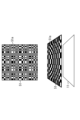
ここで、マスク51は、開口部51aと遮光部51bとが、図1(a)レンズレスカメラの下部に示すように、単位サイズΔの単位で水平方向および垂直方向について、大きさがランダムに設定されたマスクパターンを持つマスクである。単位サイズΔは、少なくとも画素サイズよりも大きいサイズである。また、画像センサ11とマスク51との間には、微小な距離dの隙間が設けられている。図に示す例では、画像センサ11上の画素間のピッチがwとされている。
このような構成により、単位サイズΔと距離dとのサイズにより光線L1乃至L3は、画像センサ11上に変調されて入射する。Here, the
With this configuration, the light beams L1 to L3 are modulated and incident on the
より詳細には、図1(a)レンズレスカメラの上図における光線L1乃至L3の光源を、例えば、図2の左上部に示すように、点光源PA,PB,PCとし、マスク51を透過して入射する画像センサ11上の位置Pa,Pb,Pcのそれぞれに光強度a,b,cの光線が入射するものとする。
More specifically, the light sources of the light rays L1 to L3 in the upper diagram of the lensless camera in FIG. It is assumed that light rays with light intensities a, b, and c are incident on positions Pa, Pb, and Pc on the
レンズレスカメラの場合、図2左上部に示すように、各画素の検出感度は、マスク51に、ランダムに設定される開口部51aより入射光が変調されることにより、入射角に応じた指向性を持つことになる。ここでいう各画素の検出感度に入射角指向性を持たせるとは、画像センサ11上の領域に応じて入射光の入射角度に応じた受光感度特性を異なるものとなるように持たせることである。
In the case of a lensless camera, as shown in the upper left part of FIG. 2, the detection sensitivity of each pixel is determined by modulating the incident light through randomly set
すなわち、被写体面71を構成する光源が点光源であることを前提とした場合、画像センサ11においては、同一の点光源より発せられた同一の光強度の光線が、入射されることになるが、マスク51により変調されることにより、画像センサ11の撮像面上の領域毎に入射角度が変化する。そして、マスク51により画像センサ11上の領域に応じて入射光の入射角度が変化することにより受光感度特性、すなわち、入射角指向性を有しているので、同一の光強度の光線であっても、画像センサ11の撮像面の前段に設けられたマスク51により画像センサ11上の領域毎に異なる感度で検出されることになり、領域毎に異なる検出信号レベルの検出信号が検出される。
That is, assuming that the light sources forming the
より具体的には、図2の右上部で示されるように、画像センサ11上の位置Pa,Pb,Pcにおける画素の検出信号レベルDA,DB,DCは、それぞれ以下の式(1)乃至式(3)で表される。
More specifically, as shown in the upper right corner of FIG. 2, the detection signal levels DA, DB, and DC of pixels at positions Pa, Pb, and Pc on the
DA=α1×a+β1×b+γ1×c ・・・(1)
DB=α2×a+β2×b+γ2×c ・・・(2)
DC=α3×a+β3×b+γ3×c ・・・(3)DA=α1×a+β1×b+γ1×c...(1)
DB=α2×a+β2×b+γ2×c...(2)
DC=α3×a+β3×b+γ3×c...(3)
ここで、α1は、画像センサ11上の位置Paにおける復元する被写体面71上の点光源PAからの光線の入射角度に応じて設定される検出信号レベルaに対する係数である。また、β1は、画像センサ11上の位置Paにおける復元する被写体面71上の点光源PBからの光線の入射角度に応じて設定される検出信号レベルbに対する係数である。さらに、γ1は、画像センサ11上の位置Paにおける復元する被写体面71上の点光源PCからの光線の入射角度に応じて設定される検出信号レベルcに対する係数である。
Here, α1 is a coefficient for the detection signal level a that is set according to the incident angle of the light ray from the point light source PA on the
従って、検出信号レベルDAのうちの(α1×a)は、位置Pcにおける点光源PAからの光線による検出信号レベルを示す値となる。また、検出信号レベルDAのうちの(β1×b)は、位置Pcにおける点光源PBからの光線による検出信号レベルを示す値となる。さらに、検出信号レベルDAのうちの(γ1×c)は、位置Pcにおける点光源PCからの光線による検出信号レベルを示す値となる。 Therefore, (α1×a) of the detection signal level DA is a value indicating the detection signal level due to the light beam from the point light source PA at the position Pc. Further, (β1×b) of the detection signal level DA is a value indicating the detection signal level due to the light beam from the point light source PB at the position Pc. Furthermore, (γ1×c) of the detection signal level DA is a value indicating the detection signal level due to the light beam from the point light source PC at the position Pc.
従って、検出信号レベルDAは、位置Paにおける点光源PA,PB,PCの各成分に、それぞれの係数α1,β1,γ1を掛けたものの合成値として表現される。
以降、係数α1、β1、γ1を合わせて係数セットと呼ぶこととする。Therefore, the detection signal level DA is expressed as a composite value obtained by multiplying each component of the point light sources PA, PB, and PC at the position Pa by the respective coefficients α1, β1, and γ1.
Hereinafter, the coefficients α1, β1, and γ1 will be collectively referred to as a coefficient set.
同様に、点光源PBにおける検出信号レベルDBについて、係数セットα2,β2,γ2は、それぞれ点光源PAにおける検出信号レベルDAについての、係数セットα1,β1,γ1に対応するものである。また、点光源PCにおける検出信号レベルDCについて、係数セットα3,β3,γ3は、それぞれ点光源PAにおける検出信号レベルDAについての、係数セットα1,β1,γ1に対応するものである。 Similarly, the coefficient sets α2, β2, and γ2 for the detection signal level DB at the point light source PB correspond to the coefficient sets α1, β1, and γ1 for the detection signal level DA at the point light source PA, respectively. Furthermore, the coefficient sets α3, β3, and γ3 for the detection signal level DC at the point light source PC correspond to the coefficient sets α1, β1, and γ1 for the detection signal level DA at the point light source PA, respectively.
ただし、位置Pa,Pb,Pcの画素の検出信号レベルについては、点光源PA,PB,PCのそれぞれより発せられた光線の光強度a,b,cと係数との積和により表現される値である。このため、これらの検出信号レベルは、点光源PA,PB,PCのそれぞれより発せられた光線の光強度a,b,cが入り交じったものとなるので、被写体の像が結像されたものとは異なるものである。 However, the detection signal level of the pixels at positions Pa, Pb, and Pc is a value expressed by the sum of products of the light intensities a, b, and c of the light rays emitted from the point light sources PA, PB, and PC, respectively, and the coefficient. It is. For this reason, these detection signal levels are a mixture of the light intensities a, b, and c of the light rays emitted from the point light sources PA, PB, and PC, so the image of the subject is It is different from
すなわち、この係数セットα1,β1,γ1,係数セットα2,β2,γ2,係数セットα3,β3,γ3と、検出信号レベルDA,DB,DCを用いた連立方程式を構成し、光強度a,b,cを解くことで、図1の右下部で示されるように各位置Pa,Pb,Pcの画素値を求める。これにより画素値の集合である復元画像(最終画像)が再構成されて復元される。 That is, a simultaneous equation is constructed using the coefficient set α1, β1, γ1, the coefficient set α2, β2, γ2, the coefficient set α3, β3, γ3, and the detection signal levels DA, DB, DC, and the light intensities a, b are , c, the pixel values at each position Pa, Pb, and Pc are determined as shown in the lower right corner of FIG. As a result, a restored image (final image), which is a set of pixel values, is reconstructed and restored.
また、図2の左上部で示される画像センサ11と被写体面71との距離が変化する場合、係数セットα1,β1,γ1,係数セットα2,β2,γ2,係数セットα3,β3,γ3は、それぞれ変化することになるが、この係数セットを変化させることで、様々な距離の被写体面の復元画像(最終画像)を再構成させることができる。
Further, when the distance between the
このため、1回の撮像により、係数セットを様々な距離に対応するものに変化させることで、撮像位置から様々な距離の被写体面の画像を再構成することができる。 Therefore, images of the subject plane at various distances from the imaging position can be reconstructed by changing the coefficient set to one corresponding to various distances by one imaging operation.
結果として、レンズレスカメラを用いた撮像においては、レンズを用いた撮像装置での撮像において合焦点がずれた状態で撮像される、いわゆる、ピンぼけといった現象を意識する必要がなく、画角内に撮像したい被写体が含まれるように撮像されていれば、距離に応じた係数セットを変化させることで様々な距離の被写体面の画像を、撮像後に再構成することができる。 As a result, when taking images using a lensless camera, there is no need to be aware of the so-called out-of-focus phenomenon, which occurs when taking images with an imaging device using a lens, and it is possible to capture images within the angle of view. If the image is captured so that the subject to be imaged is included, images of the subject plane at various distances can be reconstructed after imaging by changing the coefficient set according to the distance.
なお、図2の右上部に示す検出信号レベルは、被写体の像が結像された画像に対応する検出信号レベルではないので、画素値ではない。また、図2の右下部に示す検出信号レベルは、被写体の像が結像された画像に対応する画素毎の信号値、すなわち、復元画像(最終画像)の各画素の値なので、画素値となる。 Note that the detection signal level shown in the upper right corner of FIG. 2 is not a pixel value because it is not a detection signal level corresponding to an image in which the image of the subject is formed. In addition, the detection signal level shown in the lower right corner of Fig. 2 is the signal value for each pixel corresponding to the image in which the image of the subject is formed, that is, the value of each pixel of the restored image (final image), so it is not the pixel value. Become.
このような構成により、撮像レンズや、ピンホールを必要としない、いわゆるレンズレスカメラを実現することが可能となる。結果として、撮像レンズや、ピンホール等が必須構成とならないので、撮像装置の低背化、すなわち、撮像機能を実現する構成における光の入射方向に対する厚さを薄くすることが可能になる。また、係数セットを様々に変化させることにより、様々な距離の被写体面における復元画像(最終画像)を再構成して復元することが可能となる。 With such a configuration, it is possible to realize a so-called lensless camera that does not require an imaging lens or a pinhole. As a result, since an imaging lens, a pinhole, etc. are not required, it becomes possible to reduce the height of the imaging device, that is, to reduce the thickness of the configuration that implements the imaging function in the direction of light incidence. Furthermore, by varying the coefficient set, it is possible to reconstruct and restore restored images (final images) on object planes at various distances.
なお、以降においては、画像センサにより撮像された、再構成される前の画像を単に観測画像と称し、観測画像が信号処理されることにより再構成されて復元される画像を復元画像(最終画像)と称する。従って、1枚の観測画像からは、上述した係数セットを様々に変化させることにより、様々な距離の被写体面71上の画像を最終画像として再構成させることができる。
In the following, the image captured by the image sensor before being reconstructed will be simply referred to as the observed image, and the image reconstructed and restored by signal processing of the observed image will be referred to as the restored image (final image). ). Therefore, from one observed image, images on the
図3は、レンズレスカメラにおける撮像素子の構成例を示す図である。上部がマスク51の上面図であり、下部がマスク51と画像センサ(固体撮像素子)11とを側面上方からみた斜視図である。
FIG. 3 is a diagram showing an example of the configuration of an image sensor in a lensless camera. The upper part is a top view of the
一般的なレンズレスカメラの撮像素子は、例えば、図3に示すように、マスク51における開口部51aの単位サイズが、全領域に対して一様に設定されて、画像センサ11においては、マスク51を透過した光より全体として1枚の画像が撮像される。 In the image sensor of a general lensless camera, for example, as shown in FIG. One image is taken as a whole from the light transmitted through 51.
[2.レンズレスカメラにおける画角設定について]
次に、レンズレスカメラにおける画角設定について説明する。図4は、レンズレスカメラ80の概略構成を示す図である。図4に示すようにレンズレスカメラ80は、画像センサ81の前にマスク82を配置した構成を持つ。マスク82は、光の透過領域と不透過領域を2次元パターンとして設定したマスクである。このマスク82を介した光を画像センサに入力する。[2. About angle of view settings for lensless cameras]
Next, the angle of view setting in a lensless camera will be explained. FIG. 4 is a diagram showing a schematic configuration of the
図4では、被写体85の撮影を行い、被写体画像が復元された復元画像(最終画像)87を出力する構成例を示している。なお、画像センサ(固体撮像素子)81により撮像された再構成される前の画像が観測画像86であり、信号処理部83が観測画像86に対して信号処理を行うことで再構成されて復元される画像が復元画像(最終画像)87である。復元画像(最終画像)87は、通常のレンズ装着カメラと同様、撮影シーンの被写体を含む画像となる。
FIG. 4 shows a configuration example in which a subject 85 is photographed and a restored image (final image) 87 in which the subject image is restored is output. Note that the image captured by the image sensor (solid-state image sensor) 81 before being reconstructed is the observed image 86, and the
画像センサ81にはマスク82を介した像(観測画像86)が撮影される。マスク82を介した撮像データ、すなわち画像センサ1上の観測画像86が信号処理部83に入力される。信号処理部83は、画像センサ81上の観測画像86に対して、所定の信号処理を行うことで、一般的なカメラと同様の撮影シーンに対応する2次元画像としての復元画像(最終画像)87を生成する。
An image (observation image 86) is captured by the image sensor 81 through the mask 82. Imaging data through the mask 82, that is, the observed image 86 on the
撮影対象領域の3次元上のP個のサンプリングポイントから放射される光を、長さPのシーン放射光ベクトルxとして表記し、それを受光する画素数Nの画像センサ81の観測値を長さNのシーン観測値ベクトルyとして表現すると、その関係は、
y=Mx
上記関係式を用いて表すことができる。ここで、Mはマスク82の透過関数を表すマトリックスである。The light emitted from P sampling points on the three-dimensional area of the photographic target area is expressed as a scene emitted light vector x of length P, and the observed value of the image sensor 81 with the number of pixels of N that receives the light is expressed as the length Expressed as N scene observation value vector y, the relationship is
y=Mx
It can be expressed using the above relational expression. Here, M is a matrix representing the transmission function of the mask 82.
被写体の撮影画像(=シーンの放射光)を再現するには、この式の関係を満たすxを、センサ観測値yから求めれば良い。信号処理部83は、画像センサ81から入力するセンサ観測値yに対して、マスク82の透過関数を表すマトリックスの逆行列によって構成されるマトリックスを乗算して、シーン放射光ベクトルxを算出し、被写体85を含む復元画像(最終画像)87を構成する画素値を算出する処理を行う。
In order to reproduce the photographed image of the subject (=the emitted light of the scene), it is sufficient to find x that satisfies the relationship of this equation from the sensor observed value y. The
なお、マスク82を通して画像センサ81上に投影されるセンサ観測値の組を、シミュレーションなどで複数組求めておき、それらの組からマスク82の特性(透過関数)を表現するマスクマトリックスを予め計算しておく。信号処理部83は、このマトリックスの逆行列を適用して、画像センサ81から入力するセンサ観測値yに基づいて、撮影対象領域のサンプリングポイント毎の輝度値を復元した復元画像(最終画像)87を生成する。
Note that a plurality of sets of sensor observed values projected onto the image sensor 81 through the mask 82 are obtained through simulation, etc., and a mask matrix expressing the characteristics (transmission function) of the mask 82 is calculated in advance from these sets. I'll keep it. The
シーンの放射光を再現するには、上記式、すなわち、
y=Mx
この関係を満たすxを、センサ観測値yから求めれば良い。xは、サンプリングポイント毎の放射光ベクトルによって構成される。すなわち撮影シーンを構成するポイント単位の放射光であり、このサンプリングポイント毎の放射光ベクトルを2次元平面に展開した値が復元画像(最終画像)87の構成画素値に対応する。To reproduce the radiation of the scene, the above formula, i.e.
y=Mx
It is sufficient to find x that satisfies this relationship from the sensor observed value y. x is composed of a radiation vector for each sampling point. In other words, it is the radiation light in units of points constituting the photographed scene, and the value obtained by expanding the radiation light vector for each sampling point on a two-dimensional plane corresponds to the constituent pixel values of the restored image (final image) 87.
復元画像(最終画像)87として再現されるシーンの解像度は、シーンを構成する3次元上のサンプリングポイントの数Pを大きくすることで向上させることができる。ただし、サンプリングポイント数Pを大きくすると、シーン放射光ベクトルxを推定する時間が長くなり、画像の再構成、すなわち復元画像(最終画像)87にの生成処理に時間を要することになる The resolution of the scene reproduced as the restored image (final image) 87 can be improved by increasing the number P of three-dimensional sampling points that make up the scene. However, if the number of sampling points P is increased, the time to estimate the scene radiation vector x becomes longer, and it takes more time to reconstruct the image, that is, to generate the restored image (final image) 87.
上記式、y=Mxは、センサに入射する全ての光がセンサ上に重畳されることを示しており、復元される画像の画角(FOV:Field Of View)は、非常に広いものとなる。 The above equation, y=Mx, indicates that all the light incident on the sensor is superimposed on the sensor, and the field of view (FOV) of the restored image will be extremely wide. .
レンズレスカメラの画角(FOV)は広いため、シーン全体を表現するサンプリングポイント数が多くなる。しかし、カメラとして使用する場合、ある程度、FOVを狭めて、撮影範囲を限定したいといった場合も多い。 Since the angle of view (FOV) of a lensless camera is wide, the number of sampling points to represent the entire scene is large. However, when using it as a camera, it is often desirable to narrow the FOV to some extent to limit the photographic range.
具体例について図5を参照して説明する。図5には、レンスズレスカメラ(レンズレス撮像装置)80による画像撮影例として、
(a)画角を広くした設定の撮影画像例
(b)画角を狭くした設定の撮影画像例
これらの2つの画像撮影例を示している。ユーザ(画像撮影者)は、図5(b)に示すように、特定の被写体、例えば人の領域のみを撮影範囲として限定した画像を撮影したい場合がある。このようにレンズレスカメラ80の画角(FOV)を調整して様々な領域の画像を撮影したい場合がある。A specific example will be explained with reference to FIG. FIG. 5 shows an example of image capturing by a lensless camera (lensless imaging device) 80.
(a) Example of a photographed image with a setting with a wide angle of view (b) Example of a photographed image with a setting with a narrow angle of view These two examples of image photography are shown. As shown in FIG. 5(b), a user (image photographer) may want to capture an image in which the shooting range is limited to a specific subject, for example, a person. In this way, there are cases where it is desired to adjust the angle of view (FOV) of the
このための処理としては、撮影画像の一部のみを切り出すことも可能であるが、その場合、解像度が低下してしまうという問題が発生する。 As a process for this purpose, it is possible to cut out only a part of the photographed image, but in that case, a problem arises in that the resolution decreases.
また、上述したように、撮影画像として再現可能な3次元上のサンプリングポイント数Pを増やすことで解像度を上げるという方法もあるが、画像の再構成時間が増大するため、実用的ではないという問題がある。 Additionally, as mentioned above, there is a method of increasing the resolution by increasing the number of three-dimensional sampling points P that can be reproduced as a photographed image, but this increases the time required to reconstruct the image, making it impractical. There is.
画角(FOV)のための別の方法としては、図6に示すように、画像センサ81とマスク82の距離を変えて、画像センサ81に入射する光をハードウェア的に制限する方法もある。 Another method for determining the angle of view (FOV) is to change the distance between the image sensor 81 and the mask 82 to limit the light incident on the image sensor 81 using hardware, as shown in FIG. .
図6(a)は、画像センサ81とマスク82の距離(L1)を小さく設定して、画角を大きくした設定例である。一方、図6(b)は、画像センサ81とマスク82の距離(L2)を大きく設定して、画角を小さくした設定例である。 FIG. 6A shows a setting example in which the distance (L1) between the image sensor 81 and the mask 82 is set small to increase the angle of view. On the other hand, FIG. 6(b) is a setting example in which the distance (L2) between the image sensor 81 and the mask 82 is set large and the angle of view is made small.
画像センサ81とマスク82の距離(L1)を小さくした図6(a)の設定に対して、画像センサ81とマスク82の距離(L2)を大きくした図6(b)の設定では、画像センサ81に入射する光の角度が狭くなるため、撮影画像の画角が小さくなる。すなわち狭い領域の画像を撮影することができる。図6に示す制御は、望遠カメラと同じ効果を発生させるものである。 In contrast to the settings in FIG. 6A where the distance (L1) between the image sensor 81 and the mask 82 is small, the settings in FIG. 6B where the distance (L2) between the image sensor 81 and the mask 82 is increased, the image sensor Since the angle of light incident on 81 becomes narrower, the angle of view of the photographed image becomes smaller. In other words, it is possible to capture an image of a narrow area. The control shown in FIG. 6 produces the same effect as a telephoto camera.
この図6に示す例では、サンプリングポイントの位置をハードウェア的に制限されたものに限定する事で、解像度を保ったまま画角(FOV)を狭めることが可能である。しかし、この方法はあらかじめ決められた画角を設定する事はできるが、ズームレンズを実現するためには、マスクを動かすためのハードウェアが必要となり、マスクの位置の分だけ、カメラモジュールの高さが高くなってしまうという課題がある。 In the example shown in FIG. 6, by limiting the sampling point positions to those limited by hardware, it is possible to narrow the field of view (FOV) while maintaining the resolution. However, although this method allows you to set a predetermined angle of view, in order to realize a zoom lens, hardware is required to move the mask, and the height of the camera module is increased by the position of the mask. There is a problem that the quality becomes high.
なお、複数枚のLCDをセンサ前に配置する事で、任意の方向から光の透過/不透過を制御することは可能である。複数レイヤのLCDを制御する事で、パンティルトや、複数のROIだけを画面上に投影させることも可能である。特許文献1には、センサ前にMEMSアレイフィルタを配置し、光の透過/不透過を切り替える事で、FOVを変える手法が示されている。しかしこれらの方法はいずれも、付加的なハードウェアを必要としており、サイズやコストの増加がまぬがれない。また、マスクとして光学的なフィルタを用いているが、透過波長域以外の対策は示されておらず、例えば、遠赤外線域に対応する適切なフィルタについては言及されていなかった。
Note that by arranging a plurality of LCDs in front of the sensor, it is possible to control the transmission/non-transmission of light from any direction. By controlling multiple layers of LCDs, it is also possible to pan-tilt or project only multiple ROIs on the screen.
[3.本開示の画像処理装置の構成と処理について]
次に、図7以下を参照して、本開示の画像処理装置の構成と処理について説明する。[3. Regarding the configuration and processing of the image processing device of the present disclosure]
Next, the configuration and processing of the image processing apparatus of the present disclosure will be described with reference to FIG. 7 and subsequent figures.
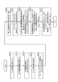
図7は、本開示の画像処理装置100の一構成例を示す図である。画像処理装置100は、レンズレスカメラ(レンズレス撮像装置)102の撮影画像を入力して、所定の画角(FOV:Field Of View)に設定された復元画像を生成して出力する信号処理部101を有する。 FIG. 7 is a diagram illustrating a configuration example of the image processing device 100 of the present disclosure. The image processing device 100 is a signal processing unit that inputs an image captured by a lensless camera (lensless imaging device) 102 and generates and outputs a restored image set at a predetermined field of view (FOV: Field of View). It has 101.
例えば、信号処理部101は、レンズレスカメラ102の画像センサの出力である観測画像信号を入力して、レンズレスカメラ101の撮影画像領域の一部からなる復元画像領域の復元画像を生成する。
For example, the
レンズレスカメラ102は、図4や図6を参照して説明した画像センサ81とマスク82によって構成されるカメラである。なお、図6を参照して説明したような画像センサ81とマスク82との距離を制御可能な構成ではなく、画像センサ81とマスク82との距離は固定されている。
The
信号処理部101は、レンズレスカメラ102の出力である撮影画像(観測値yall)を入力する。撮影画像(観測値yall)は、レンズレスカメラ102のマスクを介して受光する受光量に応じた画像センサ上の画素値である。The
信号処理部101は、この入力画像(撮影画像(観測値yall))に対する信号処理を実行して、所定の画角(FOV:Field Of View)に設定された復元画像(x^roi)を出力する。なお、(x^)は、xの上部に(^)が設定された文字を意味する。以下の説明においても同様である。他の文字でも同様であり、例えば(y^)は、yの上部に(^)が設定された文字を意味する。The
画角(FOV)は、ユーザが自由に設定可能である。レンズレスカメラ102の出力である撮影画像(観測値yall)110は、ユーザの設定する画角とは無関係の1つの固定された画角での撮影画像である。The angle of view (FOV) can be freely set by the user. The photographed image (observed value y all ) 110 that is the output of the
信号処理部101は、
(入力1)レンズレスカメラ102の出力である撮影画像(観測値yall)110、
(入力2)出力する復元画像(x^roi)の画角設定情報に相当する「復元画像領域対応ROI(Region Of Interest)情報」Rroi、
これらの情報を入力して、
(出力1)所定の画角(FOV)に設定された復元画像(x^roi)、
この出力情報を生成して出力する。The
(Input 1) Photographed image (observed value y all ) 110 that is the output of the
(Input 2) "Restored image region corresponding ROI (Region Of Interest) information" R roi corresponding to the view angle setting information of the restored image (x^ roi ) to be output,
Enter these information and
(Output 1) Restored image (x^ roi ) set to a predetermined angle of view (FOV),
Generate and output this output information.
出力データである復元画像(x^roi)に示す(x^roi)は、所定の画角内の撮影シーン(ROI)に含まれるサンプリングポイントx各々の放射光に相当する。すなわち復元画像(x^roi)は、撮影シーンの被写体像を再現した画像であり、通常のレンズありカメラによって撮影された画像と同様の画像である。(x^ roi ) shown in the restored image (x^ roi ) that is output data corresponds to the emitted light of each sampling point x included in the photographed scene (ROI) within a predetermined angle of view. That is, the restored image (x^ roi ) is an image that reproduces the subject image of the photographed scene, and is an image similar to an image photographed by a normal camera with a lens.
信号処理部101は、
撮影画像領域対応ROI情報(Rall)104、
マスク情報(IM)105、
カメラ構成情報(IC)106、
これらの情報を記憶部に保持している。なお、図7では、これらの情報を格納した記憶部を信号処理部101内部に示しているが、これらの記憶部は信号処理部101の外部に設定してもよい。The
ROI information corresponding to the photographed image area (R all ) 104,
Mask information ( IM ) 105,
Camera configuration information ( IC ) 106,
This information is held in the storage unit. Although FIG. 7 shows a storage section storing this information inside the
さらに、データ処理部として、
撮影画像領域対応マスクマトリックス(Mall)計算部107、
復元画像領域対応マストマトリックス(Mroi)計算部108、
画像推定部109を有する。Furthermore, as a data processing section,
Photographed image area corresponding mask matrix (M all )
Restored image area corresponding mast matrix (M roi )
It has an
撮影画像領域対応マスクマトリックス(Mall)計算部107は、レンズカメラ102の画像センサに撮影される撮影画像全体(全ROI)に対応するマスクマトリックス(Mall)を計算する。マスクマトリックス(Mall)は、先に説明したマスクの透過関数を表すマトリックスである。The photographed image region corresponding mask matrix (M all )
すなわち、撮影対象領域の3次元上のP個のサンプリングポイントから放射される光を、長さPのシーン放射光ベクトルxとして表記し、それを受光する画素数Nの画像センサの観測値を長さNのシーン観測値ベクトルyとして表現した場合の関係式、
y=Mx
この関係式を満たすマスクの透過関数を表すマトリックスである。In other words, the light emitted from P sampling points on the three-dimensional area of the shooting target area is expressed as a scene emitted light vector x of length P, and the observed value of an image sensor with the number of pixels of N that receives the light is expressed as a length The relational expression when expressed as a scene observation value vector y of N,
y=Mx
This is a matrix representing the transmission function of a mask that satisfies this relational expression.
一方、復元画像領域対応マストマトリックス(Mroi)計算部108は、レンズカメラ102の画像センサに撮影される撮影画像全体(全ROI)ではなく、出力データである復元画像(x^roi)に対応するマスクマトリックス(Mroi)を計算する。すなわち、レンズレスカメラ102の撮影画像領域の一部からなる復元画像領域の復元画像を生成するために適用する復元画像領域対応マスクマトリックスを計算する。On the other hand, the restored image area corresponding mast matrix (M roi )
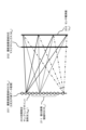
例えば、図8に示すように、レンズレスカメラ102は、固定された画角で撮影画像領域(全ROI)121の画像を撮影する。ここで、信号処理部101の出力する画像は、復元画像領域(復元ROI)122に示す限定された領域の画像であるとする。なお、図8に示す各領域は、3次元領域である。
For example, as shown in FIG. 8, the
この3次元領域は、上記の関係式、
y=Mx
この関係式のシーン放射光ベクトルxが計測されるサンプリングポイントの設定領域に相当する。撮影画像領域対応マスクマトリックス(Mall)計算部107は、例えば、図8に示す撮影画像領域(全ROI)121にサンプリングポイントを配置したと仮定した場合の、
y=Mx
上記関係式に適用可能なマスクの透過関数を表すマスクマトリックス(Mall)を算出する。このように、撮影画像領域対応マスクマトリックス(Mall)計算部107は、撮影画像領域(全ROI)121に対応するマスクマトリックス(Mall)を計算する。This three-dimensional area is expressed by the above relational expression,
y=Mx
This corresponds to the setting area of the sampling point where the scene radiation vector x in this relational expression is measured. The photographed image region corresponding mask matrix (M all )
y=Mx
A mask matrix (M all ) representing a mask transmission function applicable to the above relational expression is calculated. In this way, the photographed image region corresponding mask matrix (M all )
一方、復元画像領域対応マストマトリックス(Mroi)計算部108は、復元画像領域(復元ROI)122に対応するマスクマトリックス(Mroi)を計算する。すなわち、、例えば、図8に示す復元画像領域(復元ROI)122にサンプリングポイントを配置したと仮定した場合の、
y=Mx
上記関係式に適用可能なマスクの透過関数を表すマスクマトリックス(Mroi)を算出する。すなわち、レンズレスカメラ102の撮影画像領域の一部からなる復元画像領域の復元画像を生成するために適用する復元画像領域対応マスクマトリックスを計算する。On the other hand, the restored image region corresponding mast matrix (M roi )
y=Mx
A mask matrix (M roi ) representing a mask transmission function applicable to the above relational expression is calculated. That is, a mask matrix corresponding to the restored image area is calculated to be applied to generate a restored image of the restored image area that is a part of the image area taken by the
撮影画像領域対応マスクマトリックス(Mall)計算部107は、
撮影画像領域対応ROI情報(Rall)104、
マスク情報(IM)105、
カメラ構成情報(IC)106、
これらの情報を入力して、撮影画像領域(全ROI)121に対応するマスクマトリックス(Mall)を計算する。The photographed image area corresponding mask matrix (M all )
ROI information corresponding to the photographed image area (R all ) 104,
Mask information ( IM ) 105,
Camera configuration information ( IC ) 106,
By inputting this information, a mask matrix (M all ) corresponding to the captured image region (total ROI) 121 is calculated.
撮影画像領域対応ROI情報(Rall)104は、例えば、図8に示す撮影画像領域(全ROI)121の設定範囲情報である。さらに、この設定範囲におけるサンプリングポイントの数(P)やサンプリングポイント設定位置(x)情報も記録される。マスク情報(IM)105は、マスクの光の透過領域と不透過領域からなる2次元パターン情報等である。The ROI information corresponding to the photographed image area (R all ) 104 is, for example, setting range information of the photographed image area (all ROIs) 121 shown in FIG. 8 . Furthermore, the number (P) of sampling points in this setting range and sampling point setting position (x) information are also recorded. The mask information (I M ) 105 is two-dimensional pattern information consisting of a light-transmitting area and a non-light-transmitting area of the mask.
カメラ構成情報(IC)106は、マスクと画像センサに関する情報であり、例えば、マスクサイズ、画像センササイズ、画像センサ画素数(N)、マスクとセンサ間の距離情報等である。さらに、撮影画像領域内に設定されるサンプリングポイントの数(P)やサンプリングポイント設定位置(x)情報についても記録される。The camera configuration information (I C ) 106 is information regarding the mask and the image sensor, and includes, for example, the mask size, the image sensor size, the number of image sensor pixels (N), the distance information between the mask and the sensor, and the like. Furthermore, the number (P) of sampling points set within the photographed image area and the sampling point setting position (x) information are also recorded.
撮影画像領域対応マスクマトリックス(Mall)計算部107は、これらの情報を入力して、撮影画像領域(全ROI)121に対応するマスクマトリックス(Mall)を計算する。The photographed image region corresponding mask matrix (M all )
一方、復元画像領域対応マストマトリックス(Mroi)計算部108は、復元画像領域(復元ROI)122に対応するマスクマトリックス(Mroi)を計算する。復元画像領域対応マストマトリックス(Mroi)計算部108は、
復元画像領域対応ROI情報(Rroi)103、
マスク情報(IM)105、
カメラ構成情報(IC)106、
これらの情報を入力して、復元画像領域(復元ROI)122に対応するマスクマトリックス(Mroi)を計算する。On the other hand, the restored image region corresponding mast matrix (M roi )
ROI information corresponding to restored image area (R roi ) 103,
Mask information ( IM ) 105,
Camera configuration information ( IC ) 106,
By inputting this information, a mask matrix (M roi ) corresponding to the restored image region (restored ROI) 122 is calculated.
復元画像領域対応ROI情報(Rroi)103は、例えば、図8に示す復元画像領域(復元ROI)122の設定範囲情報である。さらに、この設定範囲におけるサンプリングポイントの数(P)やサンプリングポイント設定位置(x)情報も記録される。この復元画像領域対応ROI情報(Rroi)103は、ユーザが自由に設定可能な復元画像領域に関する情報であり、ユーザは、図示しない入力部を介して、復元画像領域対応ROI情報(Rroi)103の書き込みや更新を行うことが可能である。The restored image region corresponding ROI information (R roi ) 103 is, for example, setting range information of the restored image region (restored ROI) 122 shown in FIG. 8 . Furthermore, the number (P) of sampling points in this setting range and sampling point setting position (x) information are also recorded. The restored image area corresponding ROI information (R roi ) 103 is information regarding the restored image area that can be freely set by the user. 103 can be written and updated.
マスク情報(IM)105は、マスクの光の透過領域と不透過領域からなる2次元パターン情報等である。カメラ構成情報(IC)106は、マスクと画像センサの距離、画像センサの画素数(N)情報等である。復元画像領域対応マストマトリックス(Mroi)計算部108は、これらの情報を入力して、復元画像領域(復元ROI)122に対応するマスクマトリックス(Mall)を計算する。The mask information (I M ) 105 is two-dimensional pattern information consisting of a light-transmitting area and a non-light-transmitting area of the mask. The camera configuration information (I C ) 106 includes information on the distance between the mask and the image sensor, the number of pixels (N) of the image sensor, and the like. The restored image region corresponding mast matrix (M roi )
なお、
撮影画像領域対応マスクマトリックス(Mall)計算部107、
復元画像領域対応マストマトリックス(Mroi)計算部108、
これらのマスクマトリックス計算部の実行するマスクマトリックス計算処理の詳細シーケンスについては、図9に示すフローチャートを参照して後段において詳細に説明する。In addition,
Photographed image area corresponding mask matrix (M all )
Restored image area corresponding mast matrix (M roi )
The detailed sequence of mask matrix calculation processing executed by these mask matrix calculation units will be described in detail later with reference to the flowchart shown in FIG.
画像推定部109は、以下の各情報を入力する。(a)レンズレスカメラ102の出力である撮影画像(観測値yall)、
(b)マスク情報(IM)105、
(c)カメラ構成情報(IC)106、
(d)撮影画像領域対応ROI情報(Rall)104、
(e)復元画像領域対応ROI情報(Rroi)103、
(f)撮影画像領域対応マスクマトリックス(Mall)計算部107の算出した撮影画像領域対応マスクマトリックス(Mall)、
(g)復元画像領域対応マストマトリックス(Mroi)計算部108の算出した復元画像領域対応マストマトリックス(Mroi)、The
(b) Mask information ( IM ) 105,
(c) Camera configuration information ( IC ) 106,
(d) ROI information corresponding to the captured image area (R all ) 104;
(e) ROI information corresponding to restored image area (R roi ) 103;
(f) Mask matrix corresponding to the photographed image region (M all ) calculated by the photographed image region corresponding mask matrix (M all )
(g) Mast matrix corresponding to the restored image area (M roi ) calculated by the restored image area corresponding mast matrix (M roi )
画像推定部109は、これらの各情報を入力して、所定の画角(FOV:Field Of View)に設定された復元画像(x^roi)を出力する。出力データである復元画像(x^roi)に示す(x^roi)は、所定の画角内の撮影シーン(ROI)、例えば図8に示す復元画像領域(復元ROI)122に含まれるサンプリングポイントx各々の放射光を意味する。The
画像推定部109は、例えば、レンズレスカメラ102の画像センサの出力である観測画像信号から、復元画像領域に含まれない復元画像領域外観測画像信号を減算して、復元領域内観測画像信号を算出し、
復元領域内観測画像信号と、復元画像領域対応マスクマトリックスの疑似逆行列または逆行列との演算処理により、レンズレスカメラの撮影画像領域の一部からなる復元画像領域の復元画像を生成する。画像推定部109の実行する復元画像生成処理の詳細シーケンスについては、図10に示すフローチャートを参照して後段において詳細に説明する。For example, the
A restored image of the restored image area that is part of the captured image area of the lensless camera is generated by arithmetic processing of the observed image signal within the restored area and a pseudo inverse matrix or inverse matrix of the mask matrix corresponding to the restored image area. The detailed sequence of the restored image generation process executed by the
[4.マスクマトリックス計算部におけるマスクマトリックス計算処理の詳細シーケンスについて]
次に、図9に示すフローチャートを参照して、
撮影画像領域対応マスクマトリックス(Mall)計算部107、
復元画像領域対応マストマトリックス(Mroi)計算部108、
これらのマスクマトリックス計算部の実行するマスクマトリックス計算処理の詳細シーケンスについて説明する。[4. Regarding the detailed sequence of mask matrix calculation processing in the mask matrix calculation section]
Next, referring to the flowchart shown in FIG.
Photographed image area corresponding mask matrix (M all )
Restored image area corresponding mast matrix (M roi )
The detailed sequence of mask matrix calculation processing executed by these mask matrix calculation units will be explained.
なお、先に説明したように、
撮影画像領域対応マスクマトリックス(Mall)計算部107は、例えば図8に示す撮影画像領域(全ROI)121に対応するマスクマトリックス(Mall)を計算する。復元画像領域対応マストマトリックス(Mroi)計算部108は、例えば図8に示す復元画像領域(復元ROI)122に対応するマスクマトリックス(Mall)を計算する。それぞれ、対応領域が異なるのみであり、基本的な処理シーケンスは同じである。図9に示すステップS103のROI情報の取得処理において、取得する情報が異なるのみである。詳細は、以下の各ステップの説明中で説明する。以下、図9に示すフローチャートの各ステップの処理について、順次、説明する。Furthermore, as explained earlier,
The photographed image region corresponding mask matrix (M all )
(ステップS101)
信号処理部101の
撮影画像領域対応マスクマトリックス(Mall)計算部107、
復元画像領域対応マストマトリックス(Mroi)計算部108、
これらは、まず、ステップS101において、マスク情報IMを取得する。なお、以下では、
撮影画像領域対応マスクマトリックス(Mall)計算部107、
復元画像領域対応マストマトリックス(Mroi)計算部108、
これら2つのマスクマトリックス計算部を単にマスクマトリックス計算部として説明する。(Step S101)
a mask matrix (M all )
Restored image area corresponding mast matrix (M roi )
First, in step S101, mask information IM is acquired. In addition, below,
Photographed image area corresponding mask matrix (M all )
Restored image area corresponding mast matrix (M roi )
These two mask matrix calculation units will be explained simply as mask matrix calculation units.
ステップS101において取得するマスク情報IMは、先に説明したように、マスクの光の透過領域と不透過領域からなる2次元パターン情報等である。As described above, the mask information IM acquired in step S101 is two-dimensional pattern information consisting of a light-transmitting area and a non-light-transmitting area of the mask.
(ステップS102)
次に、マスクマトリックス計算部は、ステップS102において、カメラ構成情報ICを取得する。カメラ構成情報ICは、マスクと画像センサに関する情報であり、例えば、マスクサイズ、画像センササイズ、画像センサ画素数(N)、マスクとセンサ間の距離情報等である。(Step S102)
Next, the mask matrix calculation unit obtains camera configuration information IC in step S102. The camera configuration information IC is information regarding the mask and the image sensor, and includes, for example, the mask size, the image sensor size, the number of image sensor pixels (N), the distance information between the mask and the sensor, and the like.
(ステップS103)
次に、マスクマトリックス計算部は、ステップS103において、ROI情報を取得する。このステップS103の処理は、
撮影画像領域対応マスクマトリックス(Mall)計算部107、
復元画像領域対応マストマトリックス(Mroi)計算部108、
これらの2つのマスクマトリックス計算部において異なる処理を実行することになる。(Step S103)
Next, the mask matrix calculation unit obtains ROI information in step S103. The process of step S103 is as follows:
Photographed image area corresponding mask matrix (M all )
Restored image area corresponding mast matrix (M roi )
Different processes will be executed in these two mask matrix calculation units.
撮影画像領域対応マスクマトリックス(Mall)計算部107は、図7に示す撮影画像領域対応ROI情報(Rall)104を取得する。画像領域対応ROI情報(Rall)104は、例えば、図8に示す撮影画像領域(全ROI)121の設定範囲情報、サンプリングポイントの数(P)、設定位置(x)情報等である。すなわち、レンズレスカメラ102の画像センサが図8に示す撮影画像領域(全ROI)121におけるサンプリングポイントの放射光を撮像したと仮定した場合のROI情報である撮影画像領域対応ROI情報(Rall)104を取得する。The photographed image region corresponding mask matrix (M all )
一方、復元画像領域対応マストマトリックス(Mroi)計算部108は、図7に示す復元画像領域対応ROI情報(Rroi)103を取得する。復元画像領域対応ROI情報(Rroi)103は、例えば、図8に示す復元画像領域(復元ROI)122の設定範囲情報、サンプリングポイントの数(P)、設定位置(x)情報等である。すなわち、レンズレスカメラ102の画像センサが図8に示す図8に示す復元画像領域(復元ROI)122におけるサンプリングポイントの放射光を撮像したと仮定した場合のROI情報である復元画像領域対応ROI情報(Rroi)103を取得する。On the other hand, the restored image region corresponding mast matrix (M roi )
なお、サンプリングポイントの数(P)、設定位置(x)情報は、カメラ構成情報Ic106から取得することも可能である。 Note that the number of sampling points (P) and setting position (x) information can also be acquired from the camera configuration information Ic106.
(ステップS104)
次に、マスクマトリックス計算部は、ステップS104において、センサ画素数Nと、サンプリングポイントの位置xと、サンプリングポイント数Pを利用して、P×NのマトリックスMを用意し、初期化する。すなわち、
センサ画素数(N)と、
サンプリングポイント数(P)によって規定される
P×Nの要素(行列要素)からなるマトリックス(行列)を生成する。なお、各要素の初期値は例えば0とする。(Step S104)
Next, in step S104, the mask matrix calculation unit prepares and initializes a P×N matrix M using the number N of sensor pixels, the position x of the sampling point, and the number P of sampling points. That is,
The number of sensor pixels (N) and
A matrix consisting of P×N elements (matrix elements) defined by the number of sampling points (P) is generated. Note that the initial value of each element is, for example, 0.
なお、ここで、
撮影画像領域対応マスクマトリックス(Mall)計算部107と、
復元画像領域対応マストマトリックス(Mroi)計算部108との生成するマトリックスは異なるマトリックスである。Furthermore, here,
a photographed image area corresponding mask matrix (M all )
The matrices generated by the restored image area corresponding mast matrix (M roi )
撮影画像領域対応マスクマトリックス(Mall)計算部107は、例えば図8に示す撮影画像領域(全ROI)121に対応するマスクマトリックス(Mall)を計算するために、図8に示す撮影画像領域(全ROI)121にサンプリングポイントを設定したと仮定して、そのサンプリングポイント数Pと、センサ画素数NのP×Nの要素(行列要素)からなるマトリックス(行列)を生成する。The photographed image region corresponding mask matrix (M all )
一方、復元画像領域対応マストマトリックス(Mroi)計算部108は、例えば、図8に示す復元画像領域(復元ROI)122に対応するマスクマトリックス(Mroi)を計算するために、図8に示す復元画像領域(復元ROI)122にサンプリングポイントを設定したと仮定して、そのサンプリングポイント数Pと、センサ画素数NのP×Nの要素(行列要素)からなるマトリックス(行列)を生成する。On the other hand, the restored image region corresponding mast matrix (M roi )
なお、
撮影画像領域対応マスクマトリックス(Mall)計算部107と、
復元画像領域対応マストマトリックス(Mroi)計算部108との生成するP×Nの要素からなるマトリックスにおいて、
センサ画素数Nは、レンズレスカメラ102の画像センサの画素数(N)であり同一である。In addition,
a photographed image area corresponding mask matrix (M all )
In the matrix composed of P×N elements generated by the restored image area corresponding mast matrix (M roi )
The number N of sensor pixels is the number (N) of pixels of the image sensor of the
一方、サンプリングポイント数Pは、それぞれ自由に設定可能である。例えば、撮影画像領域対応マスクマトリックス(Mall)計算部107と、復元画像領域対応マストマトリックス(Mroi)計算部108との生成するP×Nの要素からなるマトリックスのサンプリングポイント数Pを、例えば、図8に示す撮影画像領域(全ROI)121と、復元画像領域(復元ROI)122の領域の大きさに比例した設定としてもよいし、いずれも同一のサンプリングポイント数Pとしてもよい。On the other hand, the number of sampling points P can be set freely. For example, the number of sampling points P of a matrix consisting of P×N elements generated by the photographed image area corresponding mask matrix (M all )
同一のサンプリングポイント数Pとした場合、復元画像領域(復元ROI)122の復元画像は、サンプリングポイント数Pを領域の大きさに比例した設定とした場合に比較して高解像度の画像とすることができる。前述したように、復元画像の解像度はサンプリングポイント数Pを増加させることで向上させることができる。すなわち、図8に示す復元画像領域(復元ROI)122内に高密度な多くのサンプリングポイントを設定することで、復元画像の解像度を向上させることができる。 When the number of sampling points P is the same, the restored image of the restored image region (restored ROI) 122 should be a higher resolution image than when the number of sampling points P is set proportional to the size of the region. I can do it. As described above, the resolution of the restored image can be improved by increasing the number of sampling points P. That is, by setting many high-density sampling points within the restored image region (restored ROI) 122 shown in FIG. 8, the resolution of the restored image can be improved.
(ステップS105~S106)
ステップS105以下の処理は、ステップS104において生成したマトリックスの各要素の値の設定処理である。(Steps S105 to S106)
The process from step S105 onwards is a process for setting the values of each element of the matrix generated in step S104.
まず、ステップS105~S106において、値の設定対象とするマトリックスの要素(行列要素)を選択する。最初は、ステップS105~S106において、P×Nのマトリックスの左上端の要素(p=0,n=0)を選択する。なお、p,nは、P×Nのマトリックスの要素識別インデックスである。 First, in steps S105 to S106, a matrix element (matrix element) to which a value is to be set is selected. First, in steps S105 and S106, the upper left element (p=0, n=0) of the P×N matrix is selected. Note that p and n are element identification indices of a P×N matrix.
(ステップS107)
次に、マスクマトリックス計算部は、ステップS107おいて、p番目のサンプリングポイントx(p)の光が、マスクを通してセンサ上に投影される時のn画素目のセンサ画素値(y)を求める。この画素値算出処理は、シミュレーション処理、あるいは実測処理によって行うことが可能である。(Step S107)
Next, in step S107, the mask matrix calculation unit calculates the sensor pixel value (y) of the n-th pixel when the light at the p-th sampling point x (p) is projected onto the sensor through the mask. This pixel value calculation processing can be performed by simulation processing or actual measurement processing.
(ステップS108)
次に、マスクマトリックス計算部は、ステップS108おいて、ステップの処理S107で算出したセンサ画素値(y)、
すなわち、p番目のサンプリングポイントx(p)の光が、マスクを通してセンサ上に投影される時のn画素目のセンサ画素値(y)の値を適用して、
P×Nのマスクマトリックスの選択要素(p=0,n=0)の値として、
y/x(p)
を設定する。(Step S108)
Next, in step S108, the mask matrix calculation unit calculates the sensor pixel value (y) calculated in step S107,
That is, by applying the value of the sensor pixel value (y) of the n-th pixel when the light of the p-th sampling point x (p) is projected onto the sensor through the mask,
As the value of the selected element (p=0, n=0) of the P×N mask matrix,
y/x(p)
Set.
この設定値は、先に説明した関係式、すなわち、撮影対象領域の3次元上のP個のサンプリングポイントから放射される光を、長さPのシーン放射光ベクトルxとして表記し、それを受光する画素数Nの画像センサの観測値を長さNのシーン観測値ベクトルyとした場合の関係式、
y=Mx
この関係式に従った設定値である。This setting value is based on the relational expression explained earlier, that is, the light emitted from P sampling points on the three-dimensional area of the shooting target area is expressed as a scene emitted light vector x of length P, and it is The relational expression when the observed value of the image sensor with the number of pixels N is set as the scene observed value vector y with the length N,
y=Mx
This is the set value according to this relational expression.
(ステップS109~S112)
ステップS109~S114は、値の設定対象とするマトリックスの要素(行列要素)の更新処理と、処理終了判定処理である。ステップS109で、行列要素インデックスnを1つインクリメントして、
ステップS110で、
n<N
を判定し、
n<N
であれば、
新たな行列要素(p,n)について、ステップS107~S108の処理を実行して、新たな行列要素(p,n)の値を決定する。(Steps S109 to S112)
Steps S109 to S114 are a process of updating the elements of the matrix (matrix elements) whose values are to be set, and a process of determining the end of the process. In step S109, the matrix element index n is incremented by one,
In step S110,
n<N
Determine,
n<N
If,
For the new matrix element (p, n), the processes of steps S107 to S108 are executed to determine the value of the new matrix element (p, n).
さらに、
ステップS111で、行列要素インデックスpを1つインクリメントして、
ステップS112で、
p<P
を判定し、
p<P
であれば、
新たな行列要素(p,n)について、ステップS107~S108の処理を実行して、新たな行列要素(p,n)の値を決定する。moreover,
In step S111, the matrix element index p is incremented by one,
In step S112,
p<P
Determine,
p<P
If,
For the new matrix element (p, n), the processes of steps S107 to S108 are executed to determine the value of the new matrix element (p, n).
最終的にステップS112において、
p<P
上記式を満足しないと判定されると、P×Nのマトリックスのすべての要素の値が決定され、マトリックスが完成する。Finally, in step S112,
p<P
If it is determined that the above formula is not satisfied, the values of all elements of the P×N matrix are determined, and the matrix is completed.
このフローによって生成されるマスクマトリックスは、
先に説明した関係式、すなわち、撮影対象領域の3次元上のP個のサンプリングポイントから放射される光を、長さPのシーン放射光ベクトルxとして表記し、それを受光する画素数Nの画像センサの観測値を長さNのシーン観測値ベクトルyとした場合の関係式、
y=Mx
この関係式に従ったマスクマトリックスである。The mask matrix generated by this flow is
The relational expression explained earlier, in other words, the light emitted from P sampling points on the three-dimensional area of the imaging target area is expressed as a scene emitted light vector x of length P, and the number of pixels N that receives the light is expressed as The relational expression when the observed value of the image sensor is the scene observed value vector y of length N,
y=Mx
This is a mask matrix according to this relational expression.
なお、撮影画像領域対応マスクマトリックス(Mall)計算部107が、このフローに従って生成するマスクマトリックスは、撮影画像領域対応マスクマトリックス(Mall)であり、例えば、図8に示す撮影画像領域(全ROI)121に設定したP個のサンプリングポイントの放射光をレンズレスカメラ102の画像センサが受光したと仮定した場合のセンサ画素値(y)との関係式、
y=Mx
この関係式を満たす撮影画像領域対応マスクマトリックス(Mall)である。Note that the mask matrix generated by the photographed image area corresponding mask matrix (M all )
y=Mx
This is a mask matrix (M all ) corresponding to the photographed image area that satisfies this relational expression.
一方、復元画像領域対応マストマトリックス(Mroi)計算部108が、このフローに従って生成するマスクマトリックスは、復元画像領域対応マストマトリックス(Mroi)であり、例えば、図8に示す復元画像領域(復元ROI)122に設定したP個のサンプリングポイントの放射光をレンズレスカメラ102の画像センサが受光したと仮定した場合のセンサ画素値(y)との関係式、
y=Mx
この関係式を満たす復元画像領域対応マストマトリックス(Mroi)である。On the other hand, the mask matrix that the restored image area corresponding mast matrix (M roi )
y=Mx
The restored image area corresponding mast matrix (M roi ) satisfies this relational expression.
[5.画像推定部における画像推定処理の詳細シーケンスについて]
次に、図10に示すフローチャートを参照して、
画像推定部109における画像推定処理の詳細シーケンスについて説明する。[5. Regarding the detailed sequence of image estimation processing in the image estimation section]
Next, referring to the flowchart shown in FIG.
A detailed sequence of image estimation processing in the
先に図7を参照して説明したように、画像推定部109は、
(a)レンズレスカメラ102の出力である撮影画像(観測値yall)、
(b)マスク情報(IM)105、
(c)カメラ構成情報(IC)106、
(d)撮影画像領域対応ROI情報(Rall)104、
(e)復元画像領域対応ROI情報(Rroi)103、
(f)撮影画像領域対応マスクマトリックス(Mall)計算部107の算出した撮影画像領域対応マスクマトリックス(Mall)、
(g)復元画像領域対応マストマトリックス(Mroi)計算部108の算出した復元画像領域対応マストマトリックス(Mroi)、
画像推定部109は、これらの各情報を入力して、所定の画角(FOV:Field Of View)に設定された復元画像(x^roi)を出力する。出力データである復元画像(x^roi)に示す(x^roi)は、所定の画角内の撮影シーン(ROI)、例えば図8に示す復元画像領域(復元ROI)122に含まれるサンプリングポイントx各々の放射光を意味する。As previously explained with reference to FIG. 7, the
(a) Photographed image (observed value y all ) that is the output of the
(b) Mask information ( IM ) 105,
(c) Camera configuration information ( IC ) 106,
(d) ROI information corresponding to the captured image area (R all ) 104;
(e) ROI information corresponding to restored image area (R roi ) 103;
(f) Mask matrix corresponding to the photographed image region (M all ) calculated by the photographed image region corresponding mask matrix (M all )
(g) Mast matrix corresponding to the restored image area (M roi ) calculated by the restored image area corresponding mast matrix (M roi )
The
先に説明したように、画像推定部109は、例えば、復元領域内観測画像信号と、復元画像領域対応マスクマトリックスの疑似逆行列または逆行列との演算処理により、レンズレスカメラの撮影画像領域の一部からなる復元画像領域の復元画像を生成する。
As described above, the
以下、図10に示すフローチャートの各ステップの処理について、順次、説明する。
(ステップS201)
信号処理部101の画像推定部109は、まず、ステップS201において、マスク情報IMを取得する。ステップS201において取得するマスク情報IMは、先に説明したように、マスクの光の透過領域と不透過領域からなる2次元パターン情報等である。Hereinafter, the processing of each step in the flowchart shown in FIG. 10 will be explained in order.
(Step S201)
The
(ステップS202)
次に、画像推定部109は、ステップS202において、カメラ構成情報ICを取得する。カメラ構成情報ICは、マスクと画像センサに関する情報であり、例えば、マスクサイズ、画像センササイズ、画像センサ画素数(N)、マスクとセンサ間の距離情報等である。(Step S202)
Next, the
(ステップS203)
次に、画像推定部109は、ステップS203において、ROI情報を取得する。このステップS203において、画像推定部109は、図7に示す撮影画像領域対応ROI情報(Rall)104と、復元画像領域対応ROI情報(Rroi)103を取得する。画像領域対応ROI情報(Rall)104は、例えば、図8に示す撮影画像領域(全ROI)121におけるサンプリングポイントの設定位置(x)情報である。
すなわち、レンズレスカメラ102の画像センサが図8に示す撮影画像領域(全ROI)121におけるサンプリングポイントの放射光を撮像したと仮定した場合のROI情報である。ROI情報は、再現する3次元領域の内、どの領域を再現するかの範囲を示した情報である。(Step S203)
Next, the
That is, this is ROI information when it is assumed that the image sensor of the
一方、復元画像領域対応ROI情報(Rroi)103は、例えば、図8に示す復元画像領域(復元ROI)122におけるサンプリングポイントの設定位置(x)情報である。すなわち、レンズレスカメラ102の画像センサが図8に示す復元画像領域(復元ROI)122におけるサンプリングポイントの放射光を撮像したと仮定した場合のROI情報である。On the other hand, the restored image region corresponding ROI information (R roi ) 103 is, for example, information on the setting position (x) of a sampling point in the restored image region (restored ROI) 122 shown in FIG. That is, this is ROI information assuming that the image sensor of the
このように、画像推定部109は、ステップS203において、
図7に示す撮影画像領域対応ROI情報(Rall)104と、復元画像領域対応ROI情報(Rroi)103を取得する。In this way, the
The ROI information corresponding to the captured image area (R all ) 104 and the ROI information corresponding to the restored image area (R roi ) 103 shown in FIG. 7 are acquired.
(ステップS204)
次に、画像推定部109は、ステップS204において、センサ画素数Nを取得する。すなわち、レンズレスカメラ102の画像センサのセンサ画素数(N)を取得する。この情報は、例えば、図7に示すカメラ構成情報IC106から取得する。(Step S204)
Next, the
(ステップS205)
次に、画像推定部109は、ステップS205において、サンプリングポイントの位置xと、ポイント数Pを取得する。
すなわち、
サンプリングポイント数(P)と、
各サンプリングポイントの位置(x)、
を取得する。(Step S205)
Next, the
That is,
The number of sampling points (P) and
The position of each sampling point (x),
get.
なお、これらの情報は、例えば、
カメラ構成情報(Ic)106、
撮影画像領域対応ROI情報(Rall)104、
復元画像領域対応ROI情報(Rroi)103、
これらのいずれから各々取得する。In addition, this information, for example,
Camera configuration information (Ic) 106,
ROI information corresponding to the photographed image area (R all ) 104,
ROI information corresponding to restored image area (R roi ) 103,
Obtain each from any of these.
撮影画像領域対応ROI情報(Rall)104からは、撮影画像領域内のサンプリングポイント数(P)と、各サンプリングポイントの位置(x)を取得する。具体的には、例えば、図8に示す撮影画像領域(全ROI)121に設定されたサンプリングポイントの数(P)と、位置(x)を取得する。また、復元画像領域対応ROI情報(Rroi)103からは、復元画像領域内のサンプリングポイント数(P)と、各サンプリングポイントの位置(x)を取得する。具体的には、例えば、図8に示す復元画像領域(復元ROI)122に設定されたサンプリングポイントの数(P)と、位置(x)を取得する。The number of sampling points (P) in the photographed image region and the position (x) of each sampling point are acquired from the ROI information corresponding to the photographed image region (R all ) 104 . Specifically, for example, the number (P) and position (x) of sampling points set in the photographed image region (total ROI) 121 shown in FIG. 8 are acquired. Further, from the restored image area corresponding ROI information (R roi ) 103, the number of sampling points (P) in the restored image area and the position (x) of each sampling point are acquired. Specifically, for example, the number (P) and position (x) of sampling points set in the restored image region (restored ROI) 122 shown in FIG. 8 are acquired.
(ステップS206~S207)
次に、画像推定部109は、ステップS206において、撮影画像領域対応マスクマトリックス(Mall)計算部107の算出した撮影画像領域対応マスクマトリックス(Mall)の疑似逆行列(M+
all)を算出する。さらに、ステップS207において、ステップS206で求めた疑似逆行列(M+
all)を利用して、サンプリングポイントの放射光推定値(x^all)を算出する。サンプリングポイントの放射光推定値(x^all)は、撮影シーン、例えば図8に示す撮影画像領域(全ROI)121に含まれるサンプリングポイントx各々の放射光を意味する。(Steps S206 to S207)
Next, in step S206, the
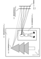
サンプリングポイントの放射光推定値(x^all)の算出処理の具体例について、図11を参照して説明する。A specific example of the process of calculating the emitted light estimated value (x^ all ) of the sampling point will be described with reference to FIG. 11.
図11には、
(a)2次元平面データとして表現した撮影画像領域ROI(Rall)201、
(b)撮影画像領域ROI(Rall)201に設定されたサンプリングポイントの放射光(x^all)204、
(c)撮影画像領域対応マスクマトリックス(Mall)202を持つマスク、
(d)撮影画像領域ROI(Rall)201に設定されたサンプリングポイントの放射光(x^all)204を画像センサによって受光した場合のセンサ観測値(画素値)(yall)203、
これらを示している。In Figure 11,
(a) Photographed image region ROI (R all ) 201 expressed as two-dimensional plane data,
(b) Synchrotron radiation (x^ all ) 204 at the sampling point set in the photographed image region ROI (R all ) 201;
(c) a mask having a mask matrix (M all ) 202 corresponding to the captured image area;
(d) Sensor observed value (pixel value) (y all ) 203 when the image sensor receives the synchrotron radiation (x^ all ) 204 of the sampling point set in the captured image region ROI (R all ) 201,
These are shown below.
すなわち、2次元平面データとして表現した撮影画像領域ROI(Rall)201に設定されたサンプリングポイントの放射光(x^all)204を、撮影画像領域対応マスクマトリックス(Mall)202を持つマスクを介して画像センサによって受光した場合のセンサ観測値(画素値)(yall)203を示している。なお、撮影画像領域ROI(Rall)は、本来、図8を参照して説明したように、3次元領域として設定されるが、3次元領域内の光は、画像センサに平行な2次元平面を通過して、画像センサに入力する。従って、3次元領域として構成される撮影画像領域ROI(Rall)は、図11に示すような2次元平面データとして表現した撮影画像領域ROI(Rall)201に変換して表現することが可能である。放射光を出力するサンプリングポイントも、この2次元平面データとして表現した撮影画像領域ROI(Rall)201内に設定して表現できる。That is, the radiation light (x^ all ) 204 of the sampling point set in the photographed image region ROI (R all ) 201 expressed as two-dimensional plane data is converted into a mask having a mask matrix (M all ) 202 corresponding to the photographed image region. The sensor observation value (pixel value) (y all ) 203 when light is received by the image sensor through the image sensor is shown. Note that the photographed image region ROI (R all ) is originally set as a three-dimensional region as explained with reference to FIG. passes through and inputs to the image sensor. Therefore, the photographed image region ROI (R all ) configured as a three-dimensional region can be converted and expressed into the photographed image region ROI (R all ) 201 expressed as two-dimensional plane data as shown in FIG. It is. A sampling point for outputting synchrotron radiation can also be set and expressed within the captured image region ROI (R all ) 201 expressed as this two-dimensional plane data.
図11に示すセンサ観測値(画素値)(yall)203は、2次元平面データとして表現した撮影画像領域ROI(Rall)201内に設定されるサンプリングポイントの各位置(xall)からの光、すなわちサンプリングポイントの放射光(x^all)204がマスクを通って写像された値である。従って、
撮影画像領域対応マスクマトリックス(Mall)202と、
センサ観測値(画素値)(yall)203、
これらの値があれば、サンプリングポイントの放射光(x^all)204の推定値を以下に示す算出処理(処理a,b)によって求めることができる。 The sensor observed values ( pixel values) (y all ) 203 shown in FIG. The light, ie the emitted light (x^ all ) 204 of the sampling point, is the value mapped through the mask. Therefore,
A mask matrix (M all ) 202 corresponding to the photographed image area,
Sensor observation value (pixel value) (y all ) 203,
If these values are available, the estimated value of the emitted light (x^ all ) 204 at the sampling point can be obtained by the calculation process (process a, b) shown below.
(処理a)
撮影画像領域対応マスクマトリックス(Mall)計算部107の算出した撮影画像領域対応マスクマトリックス(Mall)の疑似逆行列(M+
all)を、以下の(式1)に従って算出する。(Processing a)
A pseudo inverse matrix (M + all ) of the mask matrix corresponding to the photographed image area (M all ) calculated by the photographed image area corresponding mask matrix (M all ) calculation unit 107 is calculated according to the following (Formula 1).

なお、
M+
allは、撮影画像領域対応マスクマトリックス(Mall)の疑似逆行列、
MT
allは、撮影画像領域対応マスクマトリックス(Mall)の転置行列を示す。また、
(MT
allMall)-1は、(MT
allMall)の逆行列を意味する。In addition,
M + all is a pseudo inverse matrix of the mask matrix corresponding to the photographed image area (M all );
M T all indicates a transposed matrix of the mask matrix (M all ) corresponding to the photographed image area. Also,
(M T all M all ) −1 means the inverse matrix of (M T all M all ).
(処理b)
撮影画像領域対応マスクマトリックス(Mall)の疑似逆行列(M+
all)と、
センサ観測値(画素値)(yall)203、
これらの値から、サンプリングポイントの放射光(x^all)204の推定値を以下の(式2)を用いて算出する。(Processing b)
a pseudo inverse matrix (M + all ) of the mask matrix (M all ) corresponding to the photographed image area;
Sensor observation value (pixel value) (y all ) 203,
From these values, an estimated value of the emitted light (x^ all ) 204 at the sampling point is calculated using the following (Equation 2).

上記(式2)は、先に説明した関係式、すなわち、撮影対象領域の3次元上のP個のサンプリングポイントから放射される光を、長さPのシーン放射光ベクトルxとして表記し、それを受光する画素数Nの画像センサの観測値を長さNのシーン観測値ベクトルyとした場合の関係式、
y=Mx
この関係式を、行列Mの疑似逆行列(M+)を用いて表現した式に相当する。The above (Equation 2) is based on the relational expression explained earlier, that is, the light emitted from P sampling points on the three-dimensional area of the imaging target area is expressed as a scene emitted light vector x of length P, and The relational expression when the observed value of an image sensor with the number of pixels N that receives light is set to the scene observed value vector y with length N,
y=Mx
This relational expression corresponds to an expression expressed using a pseudo inverse matrix (M + ) of the matrix M.
(ステップS208~S209)
次に、画像推定部109は、ステップS208において、サンプリングポイントの放射光(x^all)204のうち、復元画像領域ROI(Rroi)に含まれないものを抽出し、これらを、復元画像領域ROI(Rroi)外サンプリングポイント放射光推定値(x^out)とする
さらに、ステップS209において、復元画像領域ROI(Rroi)外サンプリングポイント放射光推定値(x^out)に対応する観測値(y^out)を求める。(Steps S208 to S209)
Next, in step S208, the
図12に復元画像領域ROI(Rroi)211の設定例を示す。復元画像領域ROI(Rroi)211は、撮影画像領域ROI(Rall)内に自由に設定可能である。なお、図12では、復元画像領域ROI(Rroi)211も、撮影画像領域ROI(Rall)と同様、2次元データとして示している。FIG. 12 shows an example of setting the restored image region ROI (R roi ) 211. The restored image region ROI (R roi ) 211 can be freely set within the captured image region ROI (R all ). Note that in FIG. 12, the restored image region ROI (R roi ) 211 is also shown as two-dimensional data, similar to the photographed image region ROI (R all ).
ステップS208~S209の処理の詳細について説明する。ステップS208では、先に説明した(式2)、すなわち、サンプリングポイント放射光推定値(x^all)の算出式に従って算出したサンプリングポイント放射光推定値(x^all)のうち、図12に示す復元画像領域ROI(Rroi)211に含まれないサンプリングポイントを抽出し、これらを、復元画像領域ROI(Rroi)外サンプリングポイント放射光推定値(x^out)とする。Details of the processing in steps S208 to S209 will be explained. In step S208, among the estimated sampling point synchrotron radiation values (x^all) calculated according to the formula for calculating the estimated sampling point synchrotron radiation values (x^ all ), which is explained earlier (Equation 2), the estimated value of synchrotron radiation at the sampling point (x^ all ) shown in FIG. Sampling points that are not included in the restored image region ROI (R roi ) 211 are extracted, and these are set as estimated values of emitted light at sampling points outside the restored image region ROI (R roi ) (x^ out ).
次に、ステップS209において、復元画像領域ROI(Rroi)外サンプリングポイント放射光推定値(x^out)に対応する観測値(y^out)を、以下の(式3)を用いて算出する。Next, in step S209, the observed value (y^ out ) corresponding to the estimated synchrotron radiation value (x^ out ) at the sampling point outside the restored image region ROI (R roi ) is calculated using the following (Equation 3) . .

上記式は、先に説明した関係式、すなわち、撮影対象領域の3次元上のP個のサンプリングポイントから放射される光を、長さPのシーン放射光ベクトルxとして表記し、それを受光する画素数Nの画像センサの観測値を長さNのシーン観測値ベクトルyとした場合の関係式、
y=Mx
この関係式に対応する式である。The above equation is based on the relational equation explained earlier, that is, the light emitted from P sampling points on the three-dimensional area of the imaging target area is expressed as a scene emitted light vector x of length P, and the light is received. A relational expression when the observed value of an image sensor with a number of pixels of N is set as a scene observed value vector y with a length of N,
y=Mx
This is an expression corresponding to this relational expression.
図13は、ステップS209において算出される復元画像領域ROI(Rroi)外サンプリングポイント放射光推定値(x^out)に対応する観測値(y^out)を示す図である。FIG. 13 is a diagram showing the observed value (y^ out ) corresponding to the estimated radiation light value (x^ out ) at the sampling point outside the restored image region ROI (R roi ) calculated in step S209.
図13には、撮影画像領域ROI(Rall)201から、復元画像領域ROI(Rroi)211を除いた復元画像領域ROI(Rroi)外サンプリングポイント放射光(x^out)212を示している。これらの復元画像領域ROI(Rroi)外サンプリングポイント放射光(x^out)212に対応する観測値(y^out)が、図13に示す復元画像領域ROI(Rroi)外推定センサ観測値(y^out)213となる。FIG. 13 shows sampling point radiation light (x^ out ) 212 outside the restored image region ROI (R roi ), which is obtained by removing the restored image region ROI (R roi ) 211 from the captured image region ROI (R all ) 201. There is. The observed values (y^ out ) corresponding to the sampling point synchrotron radiation (x^ out ) 212 outside the restored image region ROI (R roi ) are the estimated sensor observed values outside the restored image region ROI (R roi ) shown in FIG. (y^ out ) becomes 213.
(ステップS210)
次に、画像推定部109は、ステップS210において、復元画像領域ROI(Rroi)内のサンプリングポイントの放射光(x^roi)推定値を求める。(Step S210)
Next, in step S210, the
まず、
(a)図11を参照して説明したセンサ観測値、すなわち、撮影画像領域ROI(Rall)201に設定されたサンプリングポイントの放射光(x^all)204を画像センサによって受光した場合のセンサ観測値(画素値)(yall)203から、
(b)ステップS209において算出した復元画像領域ROI(Rroi)外サンプリングポイント放射光推定値(x^out)に対応する観測値(y^out)を、
差し引く。すなわち、
(yall)-(y^out)
この減算処理によって、復元画像領域ROI(Rroi)内のサンプリングポイントからの光を観測した場合の観測値(y^roi)が得られる。first,
(a) The sensor observation value explained with reference to FIG. 11, that is, the sensor when the image sensor receives the synchrotron radiation (x^ all ) 204 of the sampling point set in the captured image region ROI (R all ) 201 From the observed value (pixel value) (y all ) 203,
(b) The observed value (y^ out ) corresponding to the estimated synchrotron radiation value (x^ out ) at the sampling point outside the restored image region ROI (R roi ) calculated in step S209 is
Subtract. That is,
(y all )-(y^ out )
Through this subtraction process, an observed value (y^ roi ) is obtained when light from a sampling point within the restored image region ROI (R roi ) is observed.
次に、復元画像領域ROI(Rroi)内のサンプリングポイントの放射光(x^roi)推定値を以下の(式4)に従って算出する。Next, the estimated value of the emitted light (x^ roi ) of the sampling point within the restored image region ROI (R roi ) is calculated according to the following (Equation 4).
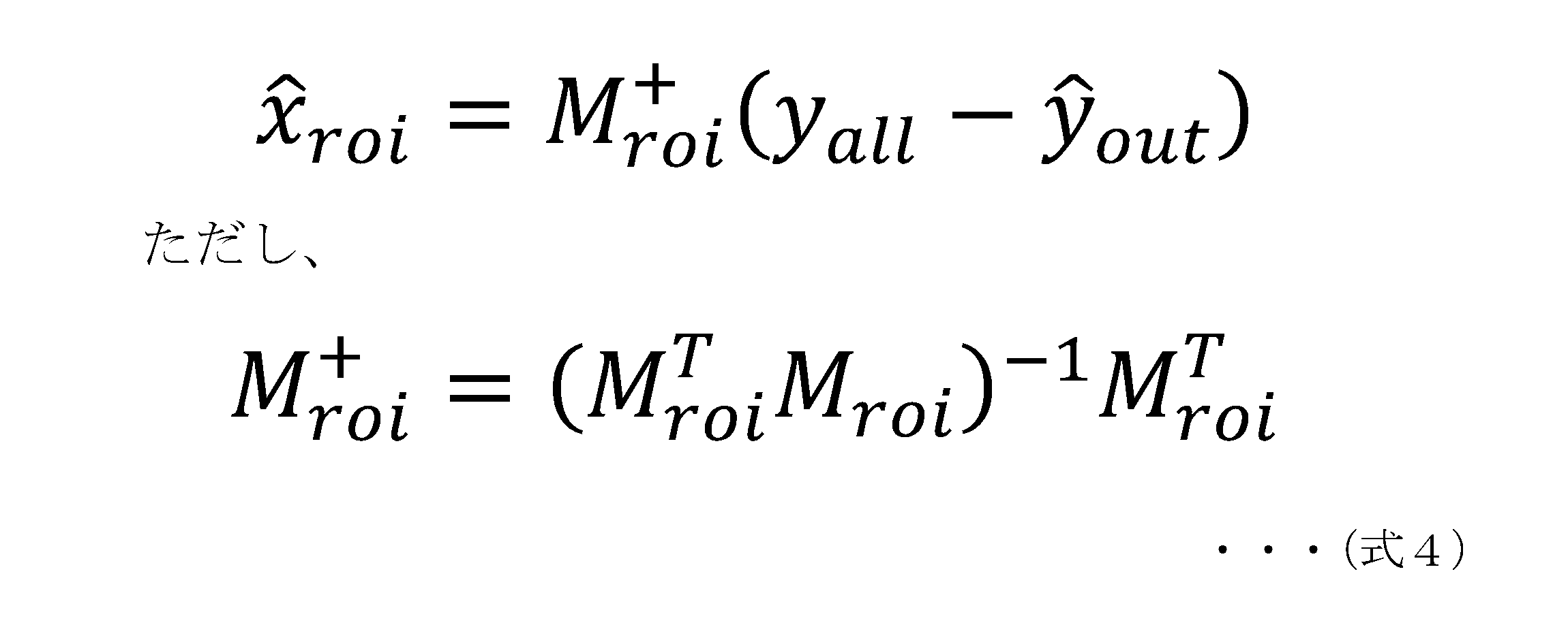
図14は、復元画像領域ROI(Rroi)内のサンプリングポイントの放射光(x^roi)推定値を算出する処理について説明する図である。図14には、撮影画像領域ROI(Rall)201内に設定された復元画像領域ROI(Rroi)211内のサンプリングポイントの放射光、すなわち、復元画像領域ROI(Rroi)内サンプリングポイント放射光(x^roi)221と、この放射光を復元画像領域対応マスクマトリックス(Mroi)222によって規定されるマスクを介して受光する画像センサの観測値、すなわち、復元画像領域ROI(Rroi)推定センサ観測値(y^roi=yall-y^out)223、これらを示している。FIG. 14 is a diagram illustrating a process for calculating an estimated value of emitted light (x^ roi ) at a sampling point within the restored image region ROI (R roi ). FIG. 14 shows the emitted light of the sampling points in the restored image region ROI (R roi ) 211 set in the photographed image region ROI (R all ) 201, that is, the radiation of the sampling points in the restored image region ROI (R roi ). The observed value of the image sensor that receives the light (x^ roi ) 221 and the emitted light through a mask defined by the restored image region corresponding mask matrix (M roi ) 222, that is, the restored image region ROI (R roi ) Estimated sensor observed values (y^ roi =y all -y^ out ) 223 are shown.
このように、画像推定部109は、上記(式4)に従って、復元画像領域ROI(Rroi)内のサンプリングポイントの放射光(x^roi)推定値を求める。この推定値は、すなわち、復元画像領域ROI(Rroi)内の被写体を示す画像(復元画像)の画素値に相当する。In this way, the
上述したように、画像推定部109は、以下の処理によってレンズレスカメラ102の撮影画像領域の一部からなる復元画像領域の復元画像を生成する。
(S206)レンズレスカメラ102の撮像範囲全体の復元画像の生成に適用する撮影画像領域対応マスクマトリックスの疑似逆行列を算出し、
(S207)撮影画像領域対応マスクマトリックスの疑似逆行列と、観測画像信号から、撮影画像領域内のサンプリングポイントの放射光推定値を算出し、As described above, the
(S206) Calculate a pseudo-inverse matrix of a mask matrix corresponding to the captured image area to be applied to generate a restored image of the entire imaging range of the
(S207) From the pseudo-inverse matrix of the mask matrix corresponding to the photographed image region and the observed image signal, calculate the estimated value of the synchrotron radiation of the sampling point within the photographed image region,
(S208~S210)レンズレスカメラ102の画像センサの出力である観測画像信号から、復元画像領域に含まれない復元画像領域外観測画像信号を減算して、復元領域内観測画像信号を算出し、復元領域内観測画像信号と、復元画像領域対応マスクマトリックスの疑似逆行列との演算処理により、レンズレスカメラ102の撮影画像領域の一部からなる復元画像領域の復元画像を生成する。
なお、これらの処理において利用する疑似逆行列は、逆行列であってもよい。(S208 to S210) subtracting an observed image signal outside the restored image area that is not included in the restored image area from the observed image signal that is the output of the image sensor of the
Note that the pseudo inverse matrix used in these processes may be an inverse matrix.
[6.サンプリングポイント設定例と画像生成例について]
先に説明した図11~図14では、説明を理解し易くするため、撮影画像領域ROI(Rall)や復元画像領域ROI(Rroi)を2次元平面データとして示して説明した。先に説明したようにこれらの領域は実際の3次元空間として表現してもよい。一般的には、サンプリングポイントは任意の3次元位置に配置する事ができる。図15は、3次元上のサンプリングポイントの輝度値から2次元画像を再構成する方法の一例を示す図である。[6. Regarding sampling point setting examples and image generation examples]
In FIGS. 11 to 14 described above, the photographed image region ROI (R all ) and the restored image region ROI (R roi ) are shown as two-dimensional plane data in order to make the explanation easier to understand. As explained above, these regions may be represented as actual three-dimensional spaces. Generally, sampling points can be placed at arbitrary three-dimensional positions. FIG. 15 is a diagram illustrating an example of a method for reconstructing a two-dimensional image from the luminance values of three-dimensional sampling points.
仮想ピンホールレンズ301と、仮想センサ面302を用意し、サンプリングポイント305,306,307からの光、すなわち、
x^all(p1)、
x^all(p2)、
x^all(p3)、
これらの光が仮想ピンホールレンズ301を通って仮想センサ面302と交差する。A virtual pinhole lens 301 and a virtual sensor surface 302 are prepared, and light from sampling points 305, 306, and 307, that is,
x^ all (p 1 ),
x^ all (p 2 ),
x^ all (p 3 ),
These lights pass through a virtual pinhole lens 301 and intersect with a virtual sensor surface 302.
仮想センサ面302上の仮想センサ画素303,304,305それぞれには、入射光に応じた観測値(画素値)、すなわち、
仮想センサ画素y(p1)303、
仮想センサ画素y(p2)304、
仮想センサ画素y(p3)305、
これらの観測値(画素値)が得られる。この場合、サンプリングポイントの距離によらず全てにピントの合った画像が再現される。Each of the virtual sensor pixels 303, 304, and 305 on the virtual sensor surface 302 has an observed value (pixel value) corresponding to the incident light, that is,
virtual sensor pixel y(p 1 ) 303,
virtual sensor pixel y(p 2 ) 304,
virtual sensor pixel y(p 3 ) 305,
These observed values (pixel values) are obtained. In this case, an image in which everything is in focus is reproduced regardless of the distance of the sampling points.
また、奥行き方向にレンズぼけが発生するような画像を再構成する方法の一例を、図16に示す。図16には、仮想レンズ311、仮想センサ面313と、仮想センサ面313で像が焦点を結ぶ仮想平面312を示している。この構成で、各サンプリングポイント316,317からの光、すなわち、
x^all(p1)、
x^all(p2)、
これらの光が仮想レンズ311を通して仮想センサ面313に写像される。この仮想センサ313上の画素値、すなわち、
仮想センサ画素y(p1)314、
仮想センサ画素y(p2)315、
これらの値を仮想センサ面313上で合成することで、奥行き方向のレンズボケを持つ画像を再現できる。Further, FIG. 16 shows an example of a method for reconstructing an image in which lens blur occurs in the depth direction. FIG. 16 shows a virtual lens 311, a virtual sensor surface 313, and a virtual plane 312 on which an image is focused on the virtual sensor surface 313. With this configuration, the light from each sampling point 316, 317, i.e.
x^ all (p 1 ),
x^ all (p 2 ),
These lights are mapped onto a virtual sensor surface 313 through a virtual lens 311 . The pixel value on this virtual sensor 313, that is,
virtual sensor pixel y(p 1 ) 314,
virtual sensor pixel y(p 2 ) 315,
By combining these values on the virtual sensor surface 313, an image with lens blur in the depth direction can be reproduced.
図17に、3次元設定としたROI領域の図を示す。ROI領域は、3次元上の任意の位置に設定できるため、サンプリングポイントを部分的に再現することができる。例えば、図17に示すような3次元空間に、
撮影画像領域ROI(Rall)321、
復元画像領域ROI(Rroi)322、
復元画像領域外ROI(Rout)323、
これらの領域を設定し、各領域に自由にサンプリングポイントを設定することができる。FIG. 17 shows a diagram of the ROI region in a three-dimensional setting. Since the ROI region can be set at any three-dimensional position, sampling points can be partially reproduced. For example, in a three-dimensional space as shown in Figure 17,
Photographed image region ROI (R all ) 321,
Restored image region ROI (R roi ) 322,
ROI outside the restored image area (R out ) 323,
These areas can be set and sampling points can be freely set in each area.
各サンプリングポイントからの放射光は、例えば図17に示す撮影画像領域対応マスクマトリックス(Mall)331に従った変換特性(透過関数)を持つマスクを介して、画像センサに入射して、センサ観測値(yall)332を観測することができる。The emitted light from each sampling point enters the image sensor through a mask having conversion characteristics (transmission function) according to the photographed image area corresponding mask matrix (M all ) 331 shown in FIG. The value (y all ) 332 can be observed.
例えば、図17に示すように、復元画像領域ROI(Rroi)322を、人のいる領域と設定する事で、人だけを含み背景領域を除去した背景除去画像を復元画像として生成することが可能である。For example, as shown in FIG. 17, by setting the restored image region ROI (R roi ) 322 as a region where there are people, a background-removed image that includes only people and removes the background region can be generated as a restored image. It is possible.
[7.部分的に解像度を向上させた画像の生成処理例について]
本開示の処理を行うことで、部分的に解像度を向上させた画像を生成することが可能となる。図18を参照して、部分的に解像度を向上させた画像の生成処理について説明する。[7. Regarding an example of image generation processing with partially improved resolution]
By performing the processing of the present disclosure, it is possible to generate an image with partially improved resolution. With reference to FIG. 18, a process for generating an image with partially improved resolution will be described.
通常のカメラ撮影画像は、画面上のピクセルピッチが一定であり、1枚の画像上の解像度は画像のどの領域でも一定となる。本開示の処理において、例えば、サンプリングポイントを一様ではなく領域毎に密度を変えることで、領域単位で解像度を変更することが可能となる。 In a normal camera-captured image, the pixel pitch on the screen is constant, and the resolution on one image is constant in any area of the image. In the process of the present disclosure, for example, by changing the density of the sampling points for each area instead of using them uniformly, it is possible to change the resolution for each area.
例えば、図18(a)に示す復元画像401のように、画像の一部を高解像度領域402に設定するといった処理が可能となる。このような画像を生成するためには、高解像度領域402に対応するサンプリングポイントの密度を、他の領域より高く設定すればよい。 For example, it is possible to set a part of the image in a high-resolution area 402, as in the restored image 401 shown in FIG. 18(a). In order to generate such an image, the density of sampling points corresponding to the high-resolution area 402 may be set higher than in other areas.
図18(b)にサンプリングポイントの密度を変えた例を示す。高密度ROI411は他の領域に比べてサンプリングポイント412が密集している。サンプリングポイントは、復元画像における画素値算出位置に対応し、サンプリングポイントの密度を高くすれば、画素値密度が高くなり、結果として高解像度の画像を生成することが可能となる。 FIG. 18(b) shows an example in which the density of sampling points is changed. In the high-density ROI 411, the sampling points 412 are more concentrated than in other regions. The sampling points correspond to pixel value calculation positions in the restored image, and if the density of the sampling points is increased, the pixel value density becomes higher, and as a result, it becomes possible to generate a high resolution image.
図19に、局所的に解像度を変更した画像の例を示す。図19に示す例は、人のいる領域のみ解像度を上げた画像を生成する処理例である。最初にシーン全体のサンプリングポイント放射光(x^all)、すなわち、撮影画像領域サンプリングポイント放射光(x^all)421を推定して、撮影画像領域全体の画像を生成する。さらに、この画像から人のいる領域を検出し、この検出領域を、高解像度化領域(Rroi)422とする。FIG. 19 shows an example of an image whose resolution has been locally changed. The example shown in FIG. 19 is a processing example of generating an image in which the resolution is increased only in an area where a person is present. First, the sampling point radiation light (x^ all ) of the entire scene, that is, the photographed image area sampling point radiation light (x^ all ) 421 is estimated to generate an image of the entire photographed image area. Furthermore, an area where a person is present is detected from this image, and this detected area is set as a high-resolution area (R roi ) 422.
次に、この高解像度化領域(Rroi)422のみ、他の領域よりサンプリングポイントの密度を上げた状態のマスクマトリックス(Mroi)をシミュレーションで算出する。このマスクマトリックス(Mroi)を特性(透過関数)として持つマスクを用いた場合の、サンプリングポイント放射光を算出する。この処理によって、人のいる領域のみ高解像度化した一部領域高解像度化画像431が生成される。Next, a mask matrix (M roi ) in which the density of sampling points is higher in only this high-resolution region (R roi ) 422 than in other regions is calculated by simulation. The sampling point emitted light is calculated when a mask having this mask matrix (M roi ) as a characteristic (transmission function) is used. Through this processing, a partial region high-resolution image 431 is generated in which only the region where there is a person is high-resolution.
このように、信号処理部109は、復元画像領域内のサンプリングポイントの密度を、レンズレスカメラ102による撮影画像のその他の領域のサンプリングポイントの密度より高密度に設定して処理を行うことで、復元画像領域のみを高解像度化した一部領域高解像度化画像を生成することができる。
In this way, the
[8.サンプリングポイントからの放射光を波長方向に分光する処理例について]
次に、サンプリングポイントからの放射光を、波長方向に分光する処理例について説明する。具体的には、例えば各サンプリングポイントの放射光をRGBの各色対応の波長光に分離して観測する処理である。この処理を行うことで、カラー画像を生成することが可能となる。[8. Regarding a processing example of dispersing the emitted light from the sampling point in the wavelength direction]
Next, an example of processing will be described in which the emitted light from the sampling point is separated in the wavelength direction. Specifically, this is a process in which, for example, the emitted light at each sampling point is separated into wavelength light corresponding to each color of RGB and observed. By performing this processing, it becomes possible to generate a color image.
図20に、サンプリングポイントからの放射光を拡張する際の模式図を示す。P個のサンプリングポイント471からの放射光をL個の波長に分離する際、p番目のサンプリングポイントから放射されるl(エル)番目の波長の放射光は、
xcol(pL+l)・・・(式a)
と表すことができる。なお、例えばサンプリングポイントからの放射光を3個の波長(R,G,B)に分離する際にはL=3、l=0~2となる。FIG. 20 shows a schematic diagram when emitted light from a sampling point is expanded. When separating the emitted light from P sampling points 471 into L wavelengths, the l-th wavelength emitted from the p-th sampling point is as follows:
x col (pL+l)...(Formula a)
It can be expressed as. Note that, for example, when separating the emitted light from the sampling point into three wavelengths (R, G, B), L=3 and l=0 to 2.
この放射光が、マスク472を介して画像センサ473のN個の構成画素のn番目の画素に入射して観測される観測値は、
ycol(nL+l)・・・(式b)
と表現できる。The observed value observed when this synchrotron radiation enters the n-th pixel of the N constituent pixels of the image sensor 473 through the mask 472 is as follows:
y col (nL+l)...(Formula b)
It can be expressed as
(式a)と(式b)の関係は、
ycol=Mcol×xcol・・・(式c)
と表すことができる。The relationship between (formula a) and (formula b) is
y col = M col ×x col ... (Formula c)
It can be expressed as.
上記(式c)において、Mcolは、
画像センサ473の画素数(N)、
サンプリングポイントからの放射光の分離波長光数(L)、
サンプリングポイント数(P)、
としたとき、
NL×PLのマトリックス(マスク472のマスクマトリックス)である。このマトリックスは、一つのサンプリングポイントからの異なる波長の放射光の観測値をシミュレートすることで求めることができる。In the above (formula c), M col is
The number of pixels (N) of the image sensor 473,
Number of separated wavelengths of emitted light from the sampling point (L),
Number of sampling points (P),
When
It is a matrix of NL×PL (mask matrix of mask 472). This matrix can be obtained by simulating the observed values of emitted light of different wavelengths from one sampling point.
これにより、画像センサ473上の観測値ycolから、サンプリングポイント501の放射光(xcol)波長毎に分離した輝度を再現することができる。例えばRGB各色の出力値を取得して、カラー画像を再現することが可能となる。なお、波長と同様に、偏光に対しても同様の拡張が可能である。Thereby, it is possible to reproduce the luminance separated for each wavelength of the emitted light (x col ) of the
このように、信号処理部109は、復元画像領域内のサンプリングポイントの放射光の波長を区分して処理を行うことで、複数の異なる波長光単位の復元画像を生成することができる。また、復元画像領域内のサンプリングポイントの放射光の偏光成分を区分して処理を行うことで、複数の異なる偏光成分単位の復元画像を生成することができる。
In this manner, the
[9.本開示の画像処理の効果について]
本開示の画像処理装置による処理を行うことで、以下のような効果を奏することができる。レンズレスカメラにハードウェアを付加することなく、高画質かつ低計算量で、メカレスズーム、メカレスパン、背景除去などの機能を実現することができる。さらに、重要でない領域の解像度を下げることで、重要領域の解像度を変えることなく、計算量の削減や、逆に計算量を維持した状態での重要領域の解像度向上などを実現できる。本開示の処理は、遠赤外線画像など、可視光以外の波長を利用した画像に対しても有効である。[9. Regarding the effects of image processing of the present disclosure]
By performing the processing by the image processing device of the present disclosure, the following effects can be achieved. Functions such as mechanical zoom, mechanical span, and background removal can be realized with high image quality and low computational complexity without adding hardware to a lensless camera. Furthermore, by lowering the resolution of unimportant areas, it is possible to reduce the amount of calculation without changing the resolution of important areas, or conversely, increase the resolution of important areas while maintaining the amount of calculation. The processing of the present disclosure is also effective for images using wavelengths other than visible light, such as far-infrared images.
[10.画像処理装置のハードウェア構成例について]
次に、図21を参照して、画像処理装置のハードウェア構成例について説明する。図21を参照して説明するハードウェアは、先に図7を参照して説明した信号処理部101の処理を実行する画像処理装置のハードウェア構成の一例である。[10. Regarding the hardware configuration example of the image processing device]
Next, an example of the hardware configuration of the image processing apparatus will be described with reference to FIG. 21. The hardware described with reference to FIG. 21 is an example of the hardware configuration of an image processing apparatus that executes the processing of the
CPU(Central Processing Unit)501は、ROM(Read Only Memory)502、または記憶部508に記憶されているプログラムに従って各種の処理を実行する制御部やデータ処理部として機能する。例えば、上述した実施例において説明したシーケンスに従った処理を実行する。RAM(Random Access Memory)503には、CPU501が実行するプログラムやデータなどが記憶される。これらのCPU501、ROM502、およびRAM503は、バス504により相互に接続されている。
A CPU (Central Processing Unit) 501 functions as a control unit or a data processing unit that executes various processes according to programs stored in a ROM (Read Only Memory) 502 or a
CPU501はバス504を介して入出力インタフェース505に接続され、入出力インタフェース505には、各種スイッチ、キーボード、マウス、マイクロホン、センサなどからなる入力部506、ディスプレイ、スピーカーなどからなる出力部507が接続されている。CPU501は、入力部506から入力される指令に対応して各種の処理を実行し、処理結果を例えば出力部507に出力する。
The
入出力インタフェース505に接続されている記憶部508は、例えばハードディスク等からなり、CPU501が実行するプログラムや各種のデータを記憶する。通信部509は、Wi-Fi通信、ブルートゥース(登録商標)(BT)通信、その他インターネットやローカルエリアネットワークなどのネットワークを介したデータ通信の送受信部として機能し、外部の装置と通信する。
A
入出力インタフェース505に接続されているドライブ510は、磁気ディスク、光ディスク、光磁気ディスク、あるいはメモリカード等の半導体メモリなどのリムーバブルメディア511を駆動し、データの記録あるいは読み取りを実行する。
A
[11.本開示の構成のまとめ]
以上、特定の実施例を参照しながら、本開示の実施例について詳解してきた。しかしながら、本開示の要旨を逸脱しない範囲で当業者が実施例の修正や代用を成し得ることは自明である。すなわち、例示という形態で本発明を開示してきたのであり、限定的に解釈されるべきではない。本開示の要旨を判断するためには、特許請求の範囲の欄を参酌すべきである。[11. Summary of structure of this disclosure]
Embodiments of the present disclosure have been described in detail above with reference to specific embodiments. However, it is obvious that those skilled in the art can modify or substitute the embodiments without departing from the gist of the present disclosure. That is, the present invention has been disclosed in the form of an example, and should not be construed in a limited manner. In order to determine the gist of the present disclosure, the claims section should be considered.
なお、本明細書において開示した技術は、以下のような構成をとることができる。
(1) レンズレスカメラの画像センサの出力である観測画像信号を入力して、前記レンズレスカメラの撮影画像領域の一部からなる復元画像領域の復元画像を生成する信号処理部を有し、
前記信号処理部は、
前記観測画像信号から前記復元画像領域に含まれない観測画像信号を減算することにより生成された復元領域内の観測画像信号と、前記復元画像の生成に適用するマトリックスの逆行列または疑似逆行列との演算処理により前記復元画像を生成する画像処理装置。Note that the technology disclosed in this specification can have the following configuration.
(1) having a signal processing unit that receives an observed image signal that is an output of an image sensor of a lensless camera and generates a restored image of a restored image area that is a part of a captured image area of the lensless camera;
The signal processing section includes:
an observed image signal in a restored region generated by subtracting an observed image signal not included in the restored image region from the observed image signal, and an inverse matrix or pseudo-inverse matrix of a matrix applied to generation of the restored image; An image processing device that generates the restored image through arithmetic processing.
(2) 前記信号処理部は、
前記復元画像領域内のサンプリングポイントからの放射光と、前記画像センサの観測値との対応関係情報に基づいて前記復元画像の生成に適用するマトリックスを生成する復元画像領域対応マトリックス計算部を有する(1)に記載の画像処理装置。(2) The signal processing section includes:
a restored image area correspondence matrix calculation unit that generates a matrix to be applied to generation of the restored image based on correspondence relationship information between the emitted light from the sampling point in the restored image area and the observed value of the image sensor; The image processing device according to item 1).
(3) 前記信号処理部は、
前記復元画像領域内のサンプリングポイント数(P)と、前記レンズレスカメラの画素数(N)によって規定されるP×Nの前記復元画像の生成に適用するマトリックスを生成する復元画像領域対応マトリックス計算部を有する(1)または(2)に記載の画像処理装置。(3) The signal processing section includes:
Restored image area correspondence matrix calculation for generating a matrix applied to generation of the P×N restored image defined by the number of sampling points (P) in the restored image area and the number of pixels (N) of the lensless camera. The image processing device according to (1) or (2).
(4) 前記信号処理部は、
前記レンズレスカメラの撮像範囲全体の復元画像の生成に適用するマトリックスの逆行列と前記観測画像信号とに基づいて算出される前記撮影画像領域内のサンプリングポイントの放射光推定値から、前記復元画像領域に含まれない観測画像信号を減算して算出される前記復元領域内の観測画像信号と、前記レンズレスカメラの撮像範囲全体の復元画像の生成に適用するマトリックスの逆行列との演算処理により、前記復元画像を生成する画像推定部を備える(1)~(3)いずれかに記載の画像処理装置。(4) The signal processing section includes:
The restored image is calculated from the emitted light estimated value of the sampling point within the captured image area, which is calculated based on the observed image signal and the inverse matrix of the matrix applied to generate the restored image of the entire imaging range of the lensless camera. By arithmetic processing of the observed image signal in the restoration area, which is calculated by subtracting the observed image signal not included in the area, and the inverse matrix of the matrix applied to generate the restored image of the entire imaging range of the lensless camera. , the image processing device according to any one of (1) to (3), comprising an image estimation unit that generates the restored image.
(5) 前記信号処理部は、さらに、
前記撮影画像領域内のサンプリングポイントからの放射光と、前記画像センサの観測値との対応関係情報に基づいて撮影画像領域に適用するマトリックスを生成する撮影画像領域対応マスクマトリックス計算部を有する(1)~(4)いずれかに記載の画像処理装置。(5) The signal processing section further includes:
a photographed image area corresponding mask matrix calculation unit that generates a matrix to be applied to the photographed image area based on correspondence relationship information between the emitted light from the sampling point in the photographed image area and the observed value of the image sensor (1); ) to (4).
(6) 前記信号処理部は、
前記復元画像領域内のサンプリングポイントの密度を、前記撮影画像のその他の領域のサンプリングポイントの密度より高密度に設定して、解像度の高い前記復元画像を生成する(1)~(5)いずれかに記載の画像処理装置。(6) The signal processing section includes:
Any one of (1) to (5), wherein the density of sampling points in the restored image area is set higher than the density of sampling points in other areas of the captured image to generate the restored image with high resolution. The image processing device described in .
(7) 前記信号処理部は、
前記復元画像領域内のサンプリングポイントの放射光の波長を区分して、複数の異なる波長光単位の復元画像を生成する(1)~(6)いずれかに記載の画像処理装置。(7) The signal processing section includes:
The image processing device according to any one of (1) to (6), which divides wavelengths of emitted light at sampling points in the restored image area to generate restored images in units of a plurality of different wavelengths.
(8) 前記信号処理部は、
前記復元画像領域内のサンプリングポイントの放射光の偏光成分を区分して、複数の異なる偏光成分単位の復元画像を生成する(1)~(7)いずれかに記載の画像処理装置。(8) The signal processing section includes:
The image processing device according to any one of (1) to (7), which divides polarization components of emitted light at sampling points in the restored image area to generate restored images in units of a plurality of different polarization components.
(9) 光の透過領域と不透過領域を2次元パターンとして設定したマスクと、
前記マスクを介した光を受光する画像センサとからなる撮像部と、
前記画像センサの出力である観測画像信号を入力して、前記撮像部の撮影画像領域の一部からなる復元画像領域の復元画像を生成する信号処理部を有し、
前記信号処理部は、
前記観測画像信号から前記復元画像領域に含まれない観測画像信号を減算することにより生成された復元領域内の観測画像信号と前記復元画像の生成に適用するマトリックスの逆行列または疑似逆行列との演算処理により前記復元画像を生成する、
撮像装置。(9) A mask with a two-dimensional pattern of light transmitting areas and non-light transmitting areas,
an imaging unit including an image sensor that receives light through the mask;
a signal processing unit that receives an observed image signal that is an output of the image sensor and generates a restored image of a restored image area that is a part of the captured image area of the imaging unit;
The signal processing section includes:
The observed image signal in the restored area generated by subtracting the observed image signal not included in the restored image area from the observed image signal and the inverse matrix or pseudo-inverse matrix of the matrix applied to the generation of the restored image. generating the restored image by arithmetic processing;
Imaging device.
(10) 画像処理装置において実行する画像処理方法であり、
前記画像処理装置は、レンズレスカメラの画像センサの出力である観測画像信号を入力して、前記レンズレスカメラの撮影画像領域の一部からなる復元画像領域の復元画像を生成する信号処理部を有し、
前記信号処理部が、
前記観測画像信号から前記復元画像領域に含まれない観測画像信号を減算することにより生成された復元領域内の観測画像信号と前記復元画像の生成に適用するマトリックスの逆行列または疑似逆行列との演算処理により前記復元画像を生成する画像処理方法。(10) An image processing method executed in an image processing device,
The image processing device includes a signal processing unit that receives an observed image signal that is an output of an image sensor of a lensless camera and generates a restored image of a restored image area that is a part of a captured image area of the lensless camera. have,
The signal processing section
The observed image signal in the restored area generated by subtracting the observed image signal not included in the restored image area from the observed image signal and the inverse matrix or pseudo-inverse matrix of the matrix applied to the generation of the restored image. An image processing method for generating the restored image through arithmetic processing.
また、明細書中において説明した一連の処理はハードウェア、またはソフトウェア、あるいは両者の複合構成によって実行することが可能である。ソフトウェアによる処理を実行する場合は、処理シーケンスを記録したプログラムを、専用のハードウェアに組み込まれたコンピュータ内のメモリにインストールして実行させるか、あるいは、各種処理が実行可能な汎用コンピュータにプログラムをインストールして実行させることが可能である。例えば、プログラムは記録媒体に予め記録しておくことができる。記録媒体からコンピュータにインストールする他、LAN(Local Area Network)、インターネットといったネットワークを介してプログラムを受信し、内蔵するハードディスク等の記録媒体にインストールすることができる。 Furthermore, the series of processes described in this specification can be executed by hardware, software, or a combination of both. When executing processing using software, a program that records the processing sequence can be installed and executed in the memory of a computer built into dedicated hardware, or the program can be installed on a general-purpose computer that can execute various types of processing. It is possible to install and run it. For example, the program can be recorded in advance on a recording medium. In addition to being installed on a computer from a recording medium, a program can be received via a network such as a LAN (Local Area Network) or the Internet, and installed on a recording medium such as a built-in hard disk.
なお、明細書に記載された各種の処理は、記載に従って時系列に実行されるのみならず、処理を実行する装置の処理能力あるいは必要に応じて並列的にあるいは個別に実行されてもよい。また、本明細書においてシステムとは、複数の装置の論理的集合構成であり、各構成の装置が同一筐体内にあるものには限らない。 Note that the various processes described in the specification are not only executed in chronological order according to the description, but also may be executed in parallel or individually depending on the processing capacity of the device executing the process or as necessary. Furthermore, in this specification, a system is a logical collective configuration of a plurality of devices, and the devices of each configuration are not limited to being in the same housing.
以上、説明したように、本開示の一実施例の構成によれば、レンズレスカメラの撮影画像の画角制御を可能とし、撮影領域の一部からなる復元画像を生成する構成が実現される。 As described above, according to the configuration of an embodiment of the present disclosure, it is possible to realize a configuration that makes it possible to control the angle of view of an image taken by a lensless camera and generates a restored image consisting of a part of the photographed area. .
80 レンズレスカメラ
81 画像センサ
82 マスク
83 信号処理部
100 画像処理装置
101 信号処理部
102 レンズレスカメラ
103 復元画像領域対応ROI情報
104 撮影画像領域対応ROI情報
105 マスク情報
106 カメラ構成情報
107 撮影画像領域対応マスクマトリックス計算部
108 復元画像領域対応マスクマトリックス計算部
109 画像推定部
501 CPU
502 ROM
503 RAM
504 バス
505 入出力インタフェース
506 入力部
507 出力部
508 記憶部
509 通信部
510 ドライブ
511 リムーバブルメディア80 Lensless camera 81 Image sensor 82
502 ROM
503 RAM
504
Claims (7)
前記信号処理部は、
前記画像センサの撮影画像全体に対応する撮影画像領域対応マスクマトリックス(M all )を算出する撮影画像領域対応マスクマトリックス(M all )計算部と、
前記画像センサの撮影画像領域の一部からなる復元画像領域の復元画像を生成するために適用する復元画像領域対応マスクマトリックス(M roi )を算出する復元画像領域対応マスクマトリックス(M roi )計算部と、
前記復元画像領域の復元画像を生成する画像推定部を有し、
前記撮影画像領域対応マスクマトリックス(M all )計算部は、
前記画像センサの撮影画像領域全体に配置したサンプリングポイントからの放射光と、前記画像センサの出力である観測画像信号との対応関係情報に基づいて前記撮影画像領域対応マスクマトリックス(M all )を算出し、
前記復元画像領域対応マスクマトリックス(M roi )計算部は、
前記復元画像領域内のサンプリングポイントからの放射光と、前記画像センサの出力である観測画像信号との対応関係情報に基づいて前記復元画像領域対応マスクマトリックス(M roi )を算出し、
前記画像推定部は、
光の透過領域と不透過領域を固定化した2次元パターンを有するマスクを介した透過光を受光して前記画像センサが出力する観測画像信号(y all )と、前記撮影画像領域対応マトリックス(M all )を適用した演算処理により、前記撮影画像領域内のサンプリングポイントの放射光推定値(x^ all )を算出する処理と、
前記撮影画像領域内のサンプリングポイントの放射光推定値(x^ all )中、前記復元画像領域に含まれないサンプリングポイントの放射光推定値である復元画像領域外放射光推定値(x^ out )を抽出する処理と、
前記撮影画像領域対応マスクマトリックス(M all )と、前記復元画像領域外放射光推定値(x^ out )を適用した運算処理により、前記復元画像領域に含まれないサンプリングポイントの観測画像信号である復元画像領域外観測画像信号(y^ out )を算出する処理と、
前記観測画像信号(y all )から前記復元画像領域外観測画像信号(y^ out )を減算することにより生成された前記復元画像領域内の観測画像信号(y all -y^ out )と、
前記復元画像領域対応マトリックス(M roi )の逆行列または疑似逆行列との演算処理により、前記復元画像領域の復元画像を生成する処理を実行する画像処理装置。 a signal processing unit that receives an observed image signal that is an output of an image sensor of a lensless camera and generates a restored image of a restored image area that is a part of a captured image area of the lensless camera;
The signal processing section includes:
a photographed image area corresponding mask matrix (M all ) calculation unit that calculates a photographed image area corresponding mask matrix (M all ) corresponding to the entire photographed image of the image sensor ;
A restored image area corresponding mask matrix (M roi ) calculation unit that calculates a restored image area corresponding mask matrix (M roi ) to be applied to generate a restored image of a restored image area consisting of a part of the captured image area of the image sensor. and,
an image estimator that generates a restored image of the restored image area;
The photographed image area corresponding mask matrix (M all ) calculation unit includes:
Calculating the photographed image area corresponding mask matrix (M all ) based on correspondence relationship information between emitted light from sampling points arranged in the entire photographed image area of the image sensor and an observed image signal that is an output of the image sensor . death,
The restored image area corresponding mask matrix (M roi ) calculation unit includes:
Calculating the restored image area corresponding mask matrix (M roi ) based on correspondence information between the emitted light from the sampling point in the restored image area and the observed image signal that is the output of the image sensor ,
The image estimation unit includes:
The observed image signal (y all ) output by the image sensor upon receiving transmitted light through a mask having a two-dimensional pattern in which a light transmitting region and a non-transmissive region are fixed, and the photographed image region correspondence matrix ( M a process of calculating an estimated radiation light value (x^ all ) of a sampling point within the photographed image area by arithmetic processing applying ``all'' ;
Among the emitted light estimated values (x^ all ) of sampling points within the photographed image area , estimated emitted light values outside the restored image area (x^ out ) are estimated emitted light values of sampling points that are not included in the restored image area. The process of extracting
An observed image signal of a sampling point that is not included in the restored image area is obtained by calculation processing using the photographed image area corresponding mask matrix (M all ) and the estimated value of emitted light outside the restored image area (x^ out ). a process of calculating an observed image signal outside the restored image area (y^ out );
an observed image signal (y all -y^ out ) within the restored image area generated by subtracting the observed image signal outside the restored image area ( y^ out ) from the observed image signal ( y all );
An image processing device that executes a process of generating a restored image of the restored image area by arithmetic processing with an inverse matrix or a pseudo-inverse matrix of the restored image area correspondence matrix (M roi ).
前記復元画像領域内のサンプリングポイント数(P)と、前記レンズレスカメラの画素数(N)によって規定されるP×Nの前記復元画像の生成に適用する復元画像領域対応マトリックスを生成する請求項1に記載の画像処理装置。 The restored image area corresponding mask matrix (M roi ) calculation unit includes:
A restored image area correspondence matrix is generated that is applied to the generation of the P×N restored image defined by the number of sampling points (P) in the restored image area and the number of pixels (N) of the lensless camera. 1. The image processing device according to 1 .
前記復元画像領域内のサンプリングポイントの密度を、前記撮影画像のその他の領域のサンプリングポイントの密度より高密度に設定して、解像度の高い前記復元画像を生成する請求項1に記載の画像処理装置。 The signal processing section includes:
The image processing device according to claim 1, wherein the density of sampling points in the restored image area is set higher than the density of sampling points in other areas of the captured image to generate the restored image with high resolution. .
前記復元画像領域内のサンプリングポイントの放射光の波長を区分して、複数の異なる波長光単位の復元画像を生成する請求項1に記載の画像処理装置。 The signal processing section includes:
The image processing apparatus according to claim 1, wherein the wavelength of the emitted light at the sampling point within the restored image area is divided to generate restored images in units of a plurality of different wavelengths.
前記復元画像領域内のサンプリングポイントの放射光の偏光成分を区分して、複数の異なる偏光成分単位の復元画像を生成する請求項1に記載の画像処理装置。 The signal processing section includes:
2. The image processing device according to claim 1, wherein polarization components of emitted light at sampling points within the restored image area are divided to generate restored images in units of a plurality of different polarization components.
前記マスクを介した光を受光する画像センサとからなる撮像部と、
前記画像センサの出力である観測画像信号を入力して、前記撮像部の撮影画像領域の一部からなる復元画像領域の復元画像を生成する信号処理部を有し、
前記信号処理部は、
前記画像センサの撮影画像全体に対応する撮影画像領域対応マスクマトリックス(M all )を算出する撮影画像領域対応マスクマトリックス(M all )計算部と、
前記画像センサの撮影画像領域の一部からなる復元画像領域の復元画像を生成するために適用する復元画像領域対応マスクマトリックス(M roi )を算出する復元画像領域対応マスクマトリックス(M roi )計算部と、
前記復元画像領域の復元画像を生成する画像推定部を有し、
前記撮影画像領域対応マスクマトリックス(M all )計算部は、
前記画像センサの撮影画像領域全体に配置したサンプリングポイントからの放射光と、前記画像センサの出力である観測画像信号との対応関係情報に基づいて前記撮影画像領域対応マスクマトリックス(M all )を算出し、
前記復元画像領域対応マスクマトリックス(M roi )計算部は、
前記復元画像領域内のサンプリングポイントからの放射光と、前記画像センサの出力である観測画像信号との対応関係情報に基づいて前記復元画像領域対応マスクマトリックス(M roi )を算出し、
前記画像推定部は、
光の透過領域と不透過領域を固定化した2次元パターンを有するマスクを介した透過光を受光して前記画像センサが出力する観測画像信号(y all )と、前記撮影画像領域対応マトリックス(M all )を適用した演算処理により、前記撮影画像領域内のサンプリングポイントの放射光推定値(x^ all )を算出する処理と、
前記撮影画像領域内のサンプリングポイントの放射光推定値(x^ all )中、前記復元画像領域に含まれないサンプリングポイントの放射光推定値である復元画像領域外放射光推定値(x^ out )を抽出する処理と、
前記撮影画像領域対応マスクマトリックス(M all )と、前記復元画像領域外放射光推定値(x^ out )を適用した運算処理により、前記復元画像領域に含まれないサンプリングポイントの観測画像信号である復元画像領域外観測画像信号(y^ out )を算出する処理と、
前記観測画像信号(y all )から前記復元画像領域外観測画像信号(y^ out )を減算することにより生成された前記復元画像領域内の観測画像信号(y all -y^ out )と、
前記復元画像領域対応マトリックス(M roi )の逆行列または疑似逆行列との演算処理により、前記復元画像領域の復元画像を生成する処理を実行する、
撮像装置。 a mask having a two-dimensional pattern in which a light-transmitting area and a non-light-transmitting area are fixed;
an imaging unit including an image sensor that receives light through the mask;
a signal processing unit that receives an observed image signal that is an output of the image sensor and generates a restored image of a restored image area that is a part of the captured image area of the imaging unit;
The signal processing section includes:
a photographed image area corresponding mask matrix (M all ) calculation unit that calculates a photographed image area corresponding mask matrix (M all ) corresponding to the entire photographed image of the image sensor ;
A restored image area corresponding mask matrix (M roi ) calculation unit that calculates a restored image area corresponding mask matrix (M roi ) to be applied to generate a restored image of a restored image area consisting of a part of the captured image area of the image sensor. and,
an image estimator that generates a restored image of the restored image area;
The photographed image area corresponding mask matrix (M all ) calculation unit includes:
Calculating the photographed image area corresponding mask matrix (M all ) based on correspondence relationship information between emitted light from sampling points arranged in the entire photographed image area of the image sensor and an observed image signal that is an output of the image sensor . death,
The restored image area corresponding mask matrix (M roi ) calculation unit includes:
Calculating the restored image area corresponding mask matrix (M roi ) based on correspondence information between the emitted light from the sampling point in the restored image area and the observed image signal that is the output of the image sensor ,
The image estimation unit includes:
The observed image signal (y all ) output by the image sensor upon receiving transmitted light through a mask having a two-dimensional pattern in which a light transmitting region and a non-transmissive region are fixed, and the photographed image region correspondence matrix ( M a process of calculating an estimated radiation light value (x^ all ) of a sampling point within the photographed image area by arithmetic processing applying ``all'' ;
Among the emitted light estimated values (x^ all ) of sampling points within the photographed image area , estimated emitted light values outside the restored image area (x^ out ) are estimated emitted light values of sampling points that are not included in the restored image area. The process of extracting
An observed image signal of a sampling point that is not included in the restored image area is obtained by calculation processing using the photographed image area corresponding mask matrix (M all ) and the estimated value of emitted light outside the restored image area (x^ out ). a process of calculating an observed image signal outside the restored image area (y^ out );
an observed image signal (y all -y^ out ) within the restored image area generated by subtracting the observed image signal outside the restored image area ( y^ out ) from the observed image signal ( y all );
performing a process of generating a restored image of the restored image area by arithmetic processing with an inverse matrix or a pseudo-inverse matrix of the restored image area correspondence matrix (M roi );
Imaging device.
前記画像処理装置は、レンズレスカメラの画像センサの出力である観測画像信号を入力して、前記レンズレスカメラの撮影画像領域の一部からなる復元画像領域の復元画像を生成する信号処理部を有し、
前記信号処理部は、
前記画像センサの撮影画像全体に対応する撮影画像領域対応マスクマトリックス(M all )を算出する撮影画像領域対応マスクマトリックス(M all )計算部と、
前記画像センサの撮影画像領域の一部からなる復元画像領域の復元画像を生成するために適用する復元画像領域対応マスクマトリックス(M roi )を算出する復元画像領域対応マスクマトリックス(M roi )計算部と、
前記復元画像領域の復元画像を生成する画像推定部を有し、
前記撮影画像領域対応マスクマトリックス(M all )計算部は、
前記画像センサの撮影画像領域全体に配置したサンプリングポイントからの放射光と、前記画像センサの出力である観測画像信号との対応関係情報に基づいて前記撮影画像領域対応マスクマトリックス(M all )を算出し、
前記復元画像領域対応マスクマトリックス(M roi )計算部は、
前記復元画像領域内のサンプリングポイントからの放射光と、前記画像センサの出力である観測画像信号との対応関係情報に基づいて前記復元画像領域対応マスクマトリックス(M roi )を算出し、
前記画像推定部は、
光の透過領域と不透過領域を固定化した2次元パターンを有するマスクを介した透過光を受光して前記画像センサが出力する観測画像信号(y all )と、前記撮影画像領域対応マトリックス(M all )を適用した演算処理により、前記撮影画像領域内のサンプリングポイントの放射光推定値(x^ all )を算出する処理と、
前記撮影画像領域内のサンプリングポイントの放射光推定値(x^ all )中、前記復元画像領域に含まれないサンプリングポイントの放射光推定値である復元画像領域外放射光推定値(x^ out )を抽出する処理と、
前記撮影画像領域対応マスクマトリックス(M all )と、前記復元画像領域外放射光推定値(x^ out )を適用した運算処理により、前記復元画像領域に含まれないサンプリングポイントの観測画像信号である復元画像領域外観測画像信号(y^ out )を算出する処理と、
前記観測画像信号(y all )から前記復元画像領域外観測画像信号(y^ out )を減算することにより生成された前記復元画像領域内の観測画像信号(y all -y^ out )と、
前記復元画像領域対応マトリックス(M roi )の逆行列または疑似逆行列との演算処理により、前記復元画像領域の復元画像を生成する処理を実行する画像処理方法。 An image processing method executed in an image processing device,
The image processing device includes a signal processing unit that receives an observed image signal that is an output of an image sensor of a lensless camera and generates a restored image of a restored image area that is a part of a captured image area of the lensless camera. have,
The signal processing section includes:
a photographed image area corresponding mask matrix (M all ) calculation unit that calculates a photographed image area corresponding mask matrix (M all ) corresponding to the entire photographed image of the image sensor ;
A restored image area corresponding mask matrix (M roi ) calculation unit that calculates a restored image area corresponding mask matrix (M roi ) to be applied to generate a restored image of a restored image area consisting of a part of the captured image area of the image sensor. and,
an image estimator that generates a restored image of the restored image area;
The photographed image area corresponding mask matrix (M all ) calculation unit includes:
Calculating the photographed image area corresponding mask matrix (M all ) based on correspondence relationship information between emitted light from sampling points arranged in the entire photographed image area of the image sensor and an observed image signal that is an output of the image sensor . death,
The restored image area corresponding mask matrix (M roi ) calculation unit includes:
Calculating the restored image area corresponding mask matrix (M roi ) based on correspondence information between the emitted light from the sampling point in the restored image area and the observed image signal that is the output of the image sensor ,
The image estimation unit includes:
The observed image signal (y all ) output by the image sensor upon receiving transmitted light through a mask having a two-dimensional pattern in which a light transmitting region and a non-transmissive region are fixed, and the photographed image region correspondence matrix ( M a process of calculating an estimated radiation light value (x^ all ) of a sampling point within the photographed image area by arithmetic processing applying ``all'' ;
Among the emitted light estimated values (x^ all ) of sampling points within the photographed image area , estimated emitted light values outside the restored image area (x^ out ) are estimated emitted light values of sampling points that are not included in the restored image area. The process of extracting
An observed image signal of a sampling point that is not included in the restored image area is obtained by calculation processing using the photographed image area corresponding mask matrix (M all ) and the estimated value of emitted light outside the restored image area (x^ out ). a process of calculating an observed image signal outside the restored image area (y^ out );
an observed image signal (y all -y^ out ) within the restored image area generated by subtracting the observed image signal outside the restored image area ( y^ out ) from the observed image signal ( y all );
An image processing method that performs a process of generating a restored image of the restored image area by arithmetic processing with an inverse matrix or a pseudo-inverse matrix of the restored image area correspondence matrix (M roi ).
Applications Claiming Priority (3)
| Application Number | Priority Date | Filing Date | Title |
|---|---|---|---|
| JP2018039315 | 2018-03-06 | ||
| JP2018039315 | 2018-03-06 | ||
| PCT/JP2018/045005 WO2019171691A1 (en) | 2018-03-06 | 2018-12-06 | Image processing device, imaging device, and image processing method |
Publications (2)
| Publication Number | Publication Date |
|---|---|
| JPWO2019171691A1 JPWO2019171691A1 (en) | 2021-03-04 |
| JP7363765B2 true JP7363765B2 (en) | 2023-10-18 |
Family
ID=67847073
Family Applications (1)
| Application Number | Title | Priority Date | Filing Date |
|---|---|---|---|
| JP2020504791A Active JP7363765B2 (en) | 2018-03-06 | 2018-12-06 | Image processing device, imaging device, and image processing method |
Country Status (4)
| Country | Link |
|---|---|
| US (1) | US11663708B2 (en) |
| JP (1) | JP7363765B2 (en) |
| CN (1) | CN111788824B (en) |
| WO (1) | WO2019171691A1 (en) |
Families Citing this family (2)
| Publication number | Priority date | Publication date | Assignee | Title |
|---|---|---|---|---|
| US20230070798A1 (en) * | 2020-03-31 | 2023-03-09 | Sony Group Corporation | Image processing apparatus and method, program, and image processing system |
| US20230367053A1 (en) * | 2020-10-16 | 2023-11-16 | Sony Group Corporation | Polarization imaging device, binary mask, image processing system, and image processing method |
Citations (3)
| Publication number | Priority date | Publication date | Assignee | Title |
|---|---|---|---|---|
| JP2008542863A (en) | 2005-05-23 | 2008-11-27 | キネテイツク・リミテツド | Coded aperture image system |
| JP2009171191A (en) | 2008-01-16 | 2009-07-30 | Sanyo Electric Co Ltd | Image pickup device and image pickup method |
| JP2016134732A (en) | 2015-01-19 | 2016-07-25 | 株式会社リコー | Imaging device and imaging method |
Family Cites Families (29)
| Publication number | Priority date | Publication date | Assignee | Title |
|---|---|---|---|---|
| TW200615605A (en) * | 2004-07-20 | 2006-05-16 | Asahi Glass Co Ltd | Liquid crystal lens element and optical head device |
| US7767949B2 (en) * | 2005-01-18 | 2010-08-03 | Rearden, Llc | Apparatus and method for capturing still images and video using coded aperture techniques |
| US8558182B2 (en) * | 2009-10-09 | 2013-10-15 | University Of Rochester | Optical element, device, method, and applications |
| US20120069209A1 (en) | 2010-09-22 | 2012-03-22 | Qualcomm Mems Technologies, Inc. | Lensless camera controlled via mems array |
| JP5709040B2 (en) * | 2010-10-27 | 2015-04-30 | 株式会社リコー | Spectral imaging device |
| JP2012124832A (en) * | 2010-12-10 | 2012-06-28 | Sony Corp | Image processing system, image processing method and program |
| KR20120080845A (en) * | 2011-01-10 | 2012-07-18 | 삼성전자주식회사 | Oled display apparatus having optical sensing funtion |
| GB2489675A (en) * | 2011-03-29 | 2012-10-10 | Sony Corp | Generating and viewing video highlights with field of view (FOV) information |
| JP2013090059A (en) * | 2011-10-14 | 2013-05-13 | Sony Corp | Image pickup device, image generation system, server, and electronic equipment |
| JP6138222B2 (en) * | 2012-02-20 | 2017-05-31 | キヤノン株式会社 | Image processing apparatus, imaging apparatus, control method, and program |
| JP6341087B2 (en) * | 2012-07-12 | 2018-06-13 | 株式会社ニコン | Image processing apparatus and image processing program |
| JP5988790B2 (en) * | 2012-09-12 | 2016-09-07 | キヤノン株式会社 | Image processing apparatus, imaging apparatus, image processing method, and image processing program |
| JP5574031B2 (en) * | 2012-12-14 | 2014-08-20 | フリュー株式会社 | Image processing apparatus and method, and program |
| JP6230239B2 (en) | 2013-02-14 | 2017-11-15 | キヤノン株式会社 | Image processing apparatus, imaging apparatus, image processing method, image processing program, and storage medium |
| US9359170B2 (en) * | 2013-10-14 | 2016-06-07 | Cedes Ag | Coding device and position-determining device and position-determining method |
| CN107005662B (en) * | 2014-07-12 | 2020-04-28 | 雷神公司 | Readout integrated circuit with integrated compressive sampling and focal plane array imaging system |
| JP6385241B2 (en) * | 2014-10-27 | 2018-09-05 | キヤノン株式会社 | Image processing apparatus, image processing method, and program |
| JP6598473B2 (en) * | 2015-02-27 | 2019-10-30 | キヤノン株式会社 | Imaging apparatus and image processing apparatus |
| US20170118489A1 (en) * | 2015-10-23 | 2017-04-27 | Broadcom Corporation | High Dynamic Range Non-Constant Luminance Video Encoding and Decoding Method and Apparatus |
| US10274652B2 (en) * | 2016-02-05 | 2019-04-30 | Rambus Inc. | Systems and methods for improving resolution in lensless imaging |
| WO2017145348A1 (en) * | 2016-02-26 | 2017-08-31 | 株式会社日立製作所 | Imaging device |
| JP6672070B2 (en) * | 2016-05-17 | 2020-03-25 | キヤノン株式会社 | Imaging apparatus using compressed sensing, imaging method, and imaging program |
| JP6688716B2 (en) * | 2016-10-04 | 2020-04-28 | 株式会社日立製作所 | Imaging device and imaging method |
| CN110140348B (en) * | 2016-12-27 | 2020-12-25 | 富士胶片株式会社 | Image pickup device and image pickup module |
| WO2018221025A1 (en) * | 2017-06-01 | 2018-12-06 | 富士フイルム株式会社 | Imaging device, image processing device, imaging system, image processing method, and recording medium |
| JP6773903B2 (en) * | 2017-06-01 | 2020-10-21 | 富士フイルム株式会社 | Image processing equipment, imaging system, image processing method, and recording medium |
| CN107290846B (en) * | 2017-08-04 | 2019-06-21 | 南京理工大学 | Quantitative phase micro imaging method based on cyclic annular programmable LED illumination |
| JP6934072B2 (en) * | 2017-12-26 | 2021-09-08 | 富士フイルム株式会社 | Imaging device |
| JP7215473B2 (en) * | 2018-03-14 | 2023-01-31 | ソニーグループ株式会社 | Image processing device, imaging device, and image processing method |
-
2018
- 2018-12-06 US US16/976,742 patent/US11663708B2/en active Active
- 2018-12-06 WO PCT/JP2018/045005 patent/WO2019171691A1/en active Application Filing
- 2018-12-06 JP JP2020504791A patent/JP7363765B2/en active Active
- 2018-12-06 CN CN201880090500.5A patent/CN111788824B/en active Active
Patent Citations (3)
| Publication number | Priority date | Publication date | Assignee | Title |
|---|---|---|---|---|
| JP2008542863A (en) | 2005-05-23 | 2008-11-27 | キネテイツク・リミテツド | Coded aperture image system |
| JP2009171191A (en) | 2008-01-16 | 2009-07-30 | Sanyo Electric Co Ltd | Image pickup device and image pickup method |
| JP2016134732A (en) | 2015-01-19 | 2016-07-25 | 株式会社リコー | Imaging device and imaging method |
Also Published As
| Publication number | Publication date |
|---|---|
| CN111788824A (en) | 2020-10-16 |
| WO2019171691A1 (en) | 2019-09-12 |
| US11663708B2 (en) | 2023-05-30 |
| CN111788824B (en) | 2022-07-08 |
| US20200410654A1 (en) | 2020-12-31 |
| JPWO2019171691A1 (en) | 2021-03-04 |
Similar Documents
| Publication | Publication Date | Title |
|---|---|---|
| US10154216B2 (en) | Image capturing apparatus, image capturing method, and storage medium using compressive sensing | |
| JP5468404B2 (en) | Imaging apparatus and imaging method, and image processing method for the imaging apparatus | |
| JP5968073B2 (en) | Image processing apparatus, imaging apparatus, image processing method, and image processing program | |
| JP2022509034A (en) | Bright spot removal using a neural network | |
| JP6838994B2 (en) | Imaging device, control method and program of imaging device | |
| JP2022501982A (en) | Photo Underexposure Compensation Using Neural Networks | |
| KR20130102550A (en) | Method for producing super-resolution images and nonlinear digital filter for implementing same | |
| JP2014158070A (en) | Image processing apparatus, image pickup apparatus, image processing method, image processing program, and storage medium | |
| JPH01309478A (en) | Picture input and output device | |
| WO2011099239A1 (en) | Imaging device and method, and image processing method for imaging device | |
| US11282176B2 (en) | Image refocusing | |
| US10171732B2 (en) | Image processing apparatus, image pickup apparatus, image processing method, and non-transitory computer-readable storage medium for generating an image based on plurality of parallax images | |
| JP2018174502A (en) | Imaging apparatus, image processing apparatus, control method of imaging apparatus, and program | |
| JP7363765B2 (en) | Image processing device, imaging device, and image processing method | |
| JP6095266B2 (en) | Image processing apparatus and control method thereof | |
| JP6418770B2 (en) | Image processing apparatus, imaging apparatus, image processing method, program, and storage medium | |
| Shroff et al. | High resolution image reconstruction for plenoptic imaging systems using system response | |
| JP4354096B2 (en) | Imaging device | |
| Nguyen et al. | Multi-mask camera model for compressed acquisition of light fields | |
| JP2021532640A (en) | A device with just two cameras and how to use this device to generate two images | |
| JP2017208642A (en) | Imaging device using compression sensing, imaging method, and imaging program | |
| JP6491442B2 (en) | Image processing apparatus, image processing method, program, and recording medium | |
| JP2017034388A (en) | Dictionary generation method, dictionary generation apparatus, image processing method, image processing apparatus, and image processing program | |
| TWI605418B (en) | Image editing method and apparatus | |
| Sun | Depth Estimation Methodology for Modern Digital Photography |
Legal Events
| Date | Code | Title | Description |
|---|---|---|---|
| A621 | Written request for application examination |
Free format text: JAPANESE INTERMEDIATE CODE: A621 Effective date: 20211015 |
|
| A131 | Notification of reasons for refusal |
Free format text: JAPANESE INTERMEDIATE CODE: A131 Effective date: 20221220 |
|
| A521 | Request for written amendment filed |
Free format text: JAPANESE INTERMEDIATE CODE: A523 Effective date: 20230120 |
|
| A02 | Decision of refusal |
Free format text: JAPANESE INTERMEDIATE CODE: A02 Effective date: 20230516 |
|
| A521 | Request for written amendment filed |
Free format text: JAPANESE INTERMEDIATE CODE: A523 Effective date: 20230524 |
|
| A911 | Transfer to examiner for re-examination before appeal (zenchi) |
Free format text: JAPANESE INTERMEDIATE CODE: A911 Effective date: 20230608 |
|
| TRDD | Decision of grant or rejection written | ||
| A01 | Written decision to grant a patent or to grant a registration (utility model) |
Free format text: JAPANESE INTERMEDIATE CODE: A01 Effective date: 20230905 |
|
| A61 | First payment of annual fees (during grant procedure) |
Free format text: JAPANESE INTERMEDIATE CODE: A61 Effective date: 20230918 |
|
| R151 | Written notification of patent or utility model registration |
Ref document number: 7363765 Country of ref document: JP Free format text: JAPANESE INTERMEDIATE CODE: R151 |