JP7363510B2 - Management device, identification information assignment method for in-vehicle devices, in-vehicle system, and data structure - Google Patents
Management device, identification information assignment method for in-vehicle devices, in-vehicle system, and data structure Download PDFInfo
- Publication number
- JP7363510B2 JP7363510B2 JP2020007269A JP2020007269A JP7363510B2 JP 7363510 B2 JP7363510 B2 JP 7363510B2 JP 2020007269 A JP2020007269 A JP 2020007269A JP 2020007269 A JP2020007269 A JP 2020007269A JP 7363510 B2 JP7363510 B2 JP 7363510B2
- Authority
- JP
- Japan
- Prior art keywords
- identification information
- vehicle
- frame
- request frame
- response frame
- Prior art date
- Legal status (The legal status is an assumption and is not a legal conclusion. Google has not performed a legal analysis and makes no representation as to the accuracy of the status listed.)
- Active
Links
Images


Classifications
-
- H—ELECTRICITY
- H04—ELECTRIC COMMUNICATION TECHNIQUE
- H04L—TRANSMISSION OF DIGITAL INFORMATION, e.g. TELEGRAPHIC COMMUNICATION
- H04L12/00—Data switching networks
- H04L12/28—Data switching networks characterised by path configuration, e.g. LAN [Local Area Networks] or WAN [Wide Area Networks]
-
- H—ELECTRICITY
- H04—ELECTRIC COMMUNICATION TECHNIQUE
- H04L—TRANSMISSION OF DIGITAL INFORMATION, e.g. TELEGRAPHIC COMMUNICATION
- H04L12/00—Data switching networks
- H04L12/28—Data switching networks characterised by path configuration, e.g. LAN [Local Area Networks] or WAN [Wide Area Networks]
- H04L12/40—Bus networks
-
- B—PERFORMING OPERATIONS; TRANSPORTING
- B60—VEHICLES IN GENERAL
- B60R—VEHICLES, VEHICLE FITTINGS, OR VEHICLE PARTS, NOT OTHERWISE PROVIDED FOR
- B60R16/00—Electric or fluid circuits specially adapted for vehicles and not otherwise provided for; Arrangement of elements of electric or fluid circuits specially adapted for vehicles and not otherwise provided for
- B60R16/02—Electric or fluid circuits specially adapted for vehicles and not otherwise provided for; Arrangement of elements of electric or fluid circuits specially adapted for vehicles and not otherwise provided for electric constitutive elements
- B60R16/023—Electric or fluid circuits specially adapted for vehicles and not otherwise provided for; Arrangement of elements of electric or fluid circuits specially adapted for vehicles and not otherwise provided for electric constitutive elements for transmission of signals between vehicle parts or subsystems
-
- H—ELECTRICITY
- H04—ELECTRIC COMMUNICATION TECHNIQUE
- H04L—TRANSMISSION OF DIGITAL INFORMATION, e.g. TELEGRAPHIC COMMUNICATION
- H04L41/00—Arrangements for maintenance, administration or management of data switching networks, e.g. of packet switching networks
- H04L41/08—Configuration management of networks or network elements
- H04L41/0803—Configuration setting
- H04L41/0806—Configuration setting for initial configuration or provisioning, e.g. plug-and-play
-
- H—ELECTRICITY
- H04—ELECTRIC COMMUNICATION TECHNIQUE
- H04L—TRANSMISSION OF DIGITAL INFORMATION, e.g. TELEGRAPHIC COMMUNICATION
- H04L43/00—Arrangements for monitoring or testing data switching networks
- H04L43/08—Monitoring or testing based on specific metrics, e.g. QoS, energy consumption or environmental parameters
- H04L43/0805—Monitoring or testing based on specific metrics, e.g. QoS, energy consumption or environmental parameters by checking availability
- H04L43/0811—Monitoring or testing based on specific metrics, e.g. QoS, energy consumption or environmental parameters by checking availability by checking connectivity
-
- H—ELECTRICITY
- H04—ELECTRIC COMMUNICATION TECHNIQUE
- H04W—WIRELESS COMMUNICATION NETWORKS
- H04W8/00—Network data management
-
- H—ELECTRICITY
- H04—ELECTRIC COMMUNICATION TECHNIQUE
- H04L—TRANSMISSION OF DIGITAL INFORMATION, e.g. TELEGRAPHIC COMMUNICATION
- H04L12/00—Data switching networks
- H04L12/28—Data switching networks characterised by path configuration, e.g. LAN [Local Area Networks] or WAN [Wide Area Networks]
- H04L12/40—Bus networks
- H04L2012/40208—Bus networks characterized by the use of a particular bus standard
- H04L2012/40215—Controller Area Network CAN
Landscapes
- Engineering & Computer Science (AREA)
- Computer Networks & Wireless Communication (AREA)
- Signal Processing (AREA)
- Mechanical Engineering (AREA)
- Databases & Information Systems (AREA)
- Environmental & Geological Engineering (AREA)
- Small-Scale Networks (AREA)
- Mobile Radio Communication Systems (AREA)
Description
本開示は、管理装置、車載装置の識別情報割り当て方法、車載システム、及びデータ構造に関する。 The present disclosure relates to a management device, a method for allocating identification information to an in-vehicle device, an in-vehicle system, and a data structure.
車載ネットワークに接続される各車載装置には固有の識別番号が割り当てられる。CAN(Controller Area Network)、FlexRay等の車載ネットワーク用通信プロトコルにおいては、車載装置の識別情報であるCAN ID、フレームID等が用いられる。 Each in-vehicle device connected to the in-vehicle network is assigned a unique identification number. In in-vehicle network communication protocols such as CAN (Controller Area Network) and FlexRay, CAN ID, frame ID, etc., which are identification information of in-vehicle devices, are used.
識別情報は、車載ネットワークにおいて一意的に定められなければならない。例えば車載ネットワークに車載装置を追加した場合、追加された車載装置に対して、他の車載装置と重複しないように識別情報を割り当てる必要がある。 Identification information must be uniquely determined in the in-vehicle network. For example, when an in-vehicle device is added to an in-vehicle network, it is necessary to assign identification information to the added in-vehicle device so that it does not overlap with other in-vehicle devices.
特許文献1には、車載ネットワークにおいてECU(Electronic Control unit)に動的に識別番号を付与する方法が開示されている。特許文献1に開示された方法では、各ECUが、複数の整数のナンバーが登録された共通ナンバーテーブルを記憶し、共通ナンバーテーブルから1つのナンバーを決定し、決定されたナンバーと自機の固有IDとを管理ECUに送信する。管理ECUは、各ECUが送信するナンバー同士に重複するナンバーがあるか否かを判定し、重複しない場合、送信されたナンバーを各ECUの識別番号として割り当て、重複する場合、そのナンバーを最小の固有IDのECUに対して割り当てる。固有IDが最小でなかったECUは、共通ナンバーテーブルから再度ナンバーを決定し、管理ECUへ送信する。
しかしながら、特許文献1に開示された方法では、同時に識別番号の付与を要求するECUが多くなると、ナンバーが重複する可能性が高くなる。つまり、ECUは他のECUがどのナンバーを決定したかを特定できないため、複数のECU間で同じナンバーを決定することが考えられる。ナンバーが重複すると、固有IDが最小でないECUは再度ナンバーの付与を要求する必要があるため、ナンバー付与に要する時間が増す。さらに、1台のECUが複数の識別番号の付与を要求することも考えられる。この場合も、ナンバーが重複する可能性が高まるため、ナンバー付与に要する時間が増加すると考えられる。
However, in the method disclosed in
本開示の一態様に係る管理装置は、車載ネットワークに接続される車載装置に識別情報を付与する管理装置であって、車載装置の固有IDを含む、識別情報付与の要求フレームを前記車載装置から受信する受信部と、前記受信部によって受信された前記要求フレームに対して割り当てられた識別情報を含む応答フレームを生成する生成部と、前記生成部によって生成された前記応答フレームを、前記要求フレームの送信元の前記車載装置へ送信する送信部と、を備える。 A management device according to an aspect of the present disclosure is a management device that assigns identification information to an in-vehicle device connected to an in-vehicle network, and receives a request frame for providing identification information, which includes a unique ID of the in-vehicle device, from the in-vehicle device. a receiving unit that receives the request frame; a generating unit that generates a response frame including identification information assigned to the request frame received by the receiving unit; a transmission unit that transmits data to the in-vehicle device that is a transmission source.
本開示の一態様に係る車載装置の識別情報割り当て方法は、車載ネットワークに接続された車載装置の識別情報割り当て方法であって、前記車載ネットワークに接続された管理装置が、車載装置の固有IDを含む、識別情報付与の要求フレームを前記車載装置から受信するステップと、前記管理装置が、受信された前記要求フレームに対して割り当てられた識別情報を含む応答フレームを生成するステップと、前記管理装置が、生成された前記応答フレームを、前記要求フレームの送信元の前記車載装置へ送信するステップと、を含む。 A method for allocating identification information for an in-vehicle device according to an aspect of the present disclosure is a method for allocating identification information for an in-vehicle device connected to an in-vehicle network, wherein a management device connected to the in-vehicle network assigns a unique ID of the in-vehicle device. a step of receiving a request frame for adding identification information from the in-vehicle device, a step of the management device generating a response frame including identification information assigned to the received request frame, and a step of the management device includes the step of transmitting the generated response frame to the in-vehicle device that is the source of the request frame.
本開示の一態様に係る車載システムは、車載ネットワークに接続される管理装置と、前記車載ネットワークに接続される車載装置と、を備え、前記車載装置は、前記車載装置の固有IDを含む、識別情報付与の要求フレームを送信する第1送信部を含み、前記管理装置は、前記車載装置から送信された前記要求フレームを受信する第2受信部と、前記第2受信部によって受信された前記要求フレームに対して割り当てられた識別情報を含む応答フレームを生成する生成部と、前記生成部によって生成された前記応答フレームを、前記要求フレームの送信元の前記車載装置へ送信する第2送信部と、を含み、前記車載装置は、前記管理装置から送信された前記応答フレームを受信する第1受信部と、前記第1受信部によって受信された前記応答フレームに含まれる識別情報を、自装置の識別情報として設定する設定部と、をさらに含む。 An in-vehicle system according to an aspect of the present disclosure includes a management device connected to an in-vehicle network, and an in-vehicle device connected to the in-vehicle network, and the in-vehicle device has an identification including a unique ID of the in-vehicle device. The management device includes a first transmitter that transmits a request frame for adding information, a second receiver that receives the request frame transmitted from the in-vehicle device, and a second receiver that transmits the request frame that is received by the second receiver. a generation unit that generates a response frame including identification information assigned to the frame; and a second transmission unit that transmits the response frame generated by the generation unit to the in-vehicle device that is the transmission source of the request frame. , the in-vehicle device includes a first receiving unit that receives the response frame transmitted from the management device, and an identification information included in the response frame received by the first receiving unit. The method further includes a setting section for setting as identification information.
本開示の一態様に係るデータ構造は、車載ネットワークに接続された車載装置が識別情報の割り当てを要求するための要求フレームに用いられるデータ構造であって、ID領域と、データ領域とを含み、前記ID領域には、前記車載ネットワークにおける共通識別情報が格納され、前記データ領域には、識別情報の割り当てを要求する車載装置の固有IDと、前記識別情報の要求数とが格納される。 A data structure according to one aspect of the present disclosure is a data structure used in a request frame for an in-vehicle device connected to an in-vehicle network to request allocation of identification information, and includes an ID area and a data area, Common identification information in the in-vehicle network is stored in the ID area, and a unique ID of an in-vehicle device requesting allocation of identification information and the number of requests for the identification information are stored in the data area.
本開示の他の態様に係るデータ構造は、車載ネットワークに接続された車載装置による識別情報の割り当て要求に応答するための応答フレームに用いられるデータ構造であって、ID領域と、データ領域とを含み、前記ID領域には、前記車載ネットワークにおける共通識別情報が格納され、前記データ領域には、識別情報の割り当てを要求する車載装置の固有IDと、前記車載装置に割り当てられた識別情報とが格納され、前記データ領域には、前記車載装置から要求された個数の前記識別情報が格納される。 A data structure according to another aspect of the present disclosure is a data structure used in a response frame for responding to a request for allocation of identification information by an in-vehicle device connected to an in-vehicle network, and includes an ID area and a data area. Common identification information in the in-vehicle network is stored in the ID area, and a unique ID of an in-vehicle device requesting allocation of identification information and identification information assigned to the in-vehicle device are stored in the data area. The number of pieces of identification information requested by the in-vehicle device is stored in the data area.
本開示は、上記のような特徴的な構成を備える管理装置として実現することができるだけでなく、管理装置における特徴的な処理をステップとする車載装置の識別情報割り当て方法として実現したり、かかるステップをコンピュータに実行させるためのコンピュータプログラムとして実現したりすることができる。管理装置の一部又は全部を半導体集積回路として実現したり、管理装置を含む車載システムとして実現したりすることができる。さらに本開示は、上記の車載装置の識別情報割り当て方法に用いられるデータ構造としても実現することができる。 The present disclosure can be realized not only as a management device having the above-described characteristic configuration, but also as a method for allocating identification information for an in-vehicle device that includes steps of characteristic processing in the management device, or It can be realized as a computer program for causing a computer to execute. Part or all of the management device can be realized as a semiconductor integrated circuit, or can be realized as an in-vehicle system including the management device. Furthermore, the present disclosure can be realized as a data structure used in the above-described identification information assignment method for an in-vehicle device.
本開示によれば、複数の車載装置が同時に識別情報の割り当てを要求したり、1台の車載装置が複数の識別情報の割り当てを要求したりする場合に、識別番号の割り当てに要する時間の増加を抑制することができる。 According to the present disclosure, when multiple in-vehicle devices simultaneously request allocation of identification information or one in-vehicle device requests allocation of multiple identification information, the time required to allocate an identification number increases. can be suppressed.
<本開示の実施形態の概要>
以下、本開示の実施形態の概要を列記して説明する。
<Summary of embodiments of the present disclosure>
Hereinafter, an overview of the embodiments of the present disclosure will be listed and described.
(1) 本実施形態に係る管理装置は、車載ネットワークに接続される車載装置に識別情報を付与する管理装置であって、車載装置の固有IDを含む、識別情報付与の要求フレームを前記車載装置から受信する受信部と、前記受信部によって受信された前記要求フレームに対して割り当てられた識別情報を含む応答フレームを生成する生成部と、前記生成部によって生成された前記応答フレームを、前記要求フレームの送信元の前記車載装置へ送信する送信部と、を備える。これにより、車載装置から送信された要求フレームに応じて、車載装置とは異なる装置が、車載装置間で重複しないように識別情報を割り当てることができる。つまり、識別情報を割り当てる装置は、各車載装置に割り当てられる識別情報を特定し得るため、1つの車載装置に割り当てられた識別情報を他の車載装置に割り当てないようにすることができる。したがって、複数の車載装置が同時に識別情報の割り当てを要求したり、1台の車載装置が複数の識別情報の割り当てを要求したりする場合に、識別番号の割り当てに要する時間の増加を抑制することができる。 (1) The management device according to the present embodiment is a management device that assigns identification information to an in-vehicle device connected to an in-vehicle network, and sends a request frame for assigning identification information that includes a unique ID of the in-vehicle device to the in-vehicle device. a generating unit that generates a response frame including identification information assigned to the request frame received by the receiving unit; and a transmitter that transmits the frame to the in-vehicle device that is the source of the frame. Thereby, a device different from the on-vehicle device can allocate identification information in response to a request frame transmitted from the on-vehicle device so as not to overlap between the on-vehicle devices. That is, since the device that allocates identification information can specify the identification information to be assigned to each vehicle-mounted device, it is possible to prevent the identification information assigned to one vehicle-mounted device from being assigned to another vehicle-mounted device. Therefore, when multiple in-vehicle devices simultaneously request allocation of identification information, or when one in-vehicle device requests allocation of multiple identification information, it is possible to suppress an increase in the time required for allocating identification numbers. I can do it.
(2) 本実施形態に係る管理装置において、前記要求フレームは、要求された識別情報の個数をさらに含み、前記応答フレームは、互いに異なる識別情報を前記個数含んでもよい。これにより、1台の車載装置に対して複数の識別情報を付与することができる。 (2) In the management device according to the present embodiment, the request frame may further include the number of pieces of requested identification information, and the response frame may include the number of pieces of mutually different pieces of identification information. Thereby, a plurality of pieces of identification information can be assigned to one in-vehicle device.
(3) 本実施形態に係る管理装置において、前記応答フレームは、正常応答フレームと、異常応答フレームとを含み、前記生成部は、前記識別情報が割り当てられた場合に、割り当てられた前記識別情報を含む前記正常応答フレームを生成し、前記生成部は、前記識別情報が割り当てられなかった場合に、前記識別情報を含まない前記異常応答フレームを生成し、前記送信部は、前記生成部によって生成された前記正常応答フレーム、又は、前記異常応答フレームを、前記送信元の前記車載装置へ送信してもよい。これにより、車載装置が正常応答フレームを受信した場合には、車載装置は正常応答フレームに含まれる識別情報を取得することができる。車載装置が異常応答フレームを受信した場合には、車載装置は識別情報を取得することなく、再度要求フレームを送信するなど必要な処置を執ることができる。 (3) In the management device according to the present embodiment, the response frame includes a normal response frame and an abnormal response frame, and when the identification information is assigned, the generation unit generates the assigned identification information. the generation unit generates the abnormal response frame that does not include the identification information when the identification information is not assigned, and the transmission unit generates the abnormal response frame that does not include the identification information, and the transmission unit generates the abnormal response frame that includes the identification information. The normal response frame or the abnormal response frame may be transmitted to the in-vehicle device that is the transmission source. Thereby, when the in-vehicle device receives the normal response frame, the in-vehicle device can acquire the identification information included in the normal response frame. When the in-vehicle device receives the abnormality response frame, the in-vehicle device can take necessary measures such as transmitting the request frame again without acquiring identification information.
(4) 本実施形態に係る管理装置は、車載装置の固有IDと、車載装置が接続されるネットワークバスのチャンネルとの対応関係を示す対応テーブルを記憶する記憶部と、前記受信部によって受信された前記要求フレームに含まれる前記固有IDと、前記要求フレームが伝送されたネットワークバスのチャンネルとの対応関係が、前記対応テーブルに示される対応関係と一致するか否かを判定する接続状態判定部と、をさらに備え、前記生成部は、前記接続状態判定部によって、前記要求フレームに含まれる前記固有IDと、前記要求フレームが伝送された前記チャンネルとの対応関係が、前記テーブルに示される前記対応関係と一致すると判定された場合、前記正常応答フレームを生成し、前記生成部は、前記接続状態判定部によって、前記要求フレームに含まれる前記固有IDと、前記要求フレームが伝送された前記チャンネルとの対応関係が、前記テーブルに示される前記対応関係と一致しないと判定された場合、前記異常応答フレームを生成してもよい。これにより、車載装置が正しいチャンネルに接続されていない場合には、当該車載装置に識別情報を割り当てることなく、異常応答フレームを送信することで接続異常を通知することができる。 (4) The management device according to the present embodiment includes a storage unit that stores a correspondence table indicating a correspondence relationship between a unique ID of an in-vehicle device and a channel of a network bus to which the in-vehicle device is connected; a connection state determination unit that determines whether a correspondence relationship between the unique ID included in the request frame and a channel of a network bus to which the request frame was transmitted matches a correspondence relationship shown in the correspondence table; The generating unit further comprises: the connection state determination unit determining the correspondence relationship between the unique ID included in the request frame and the channel to which the request frame was transmitted, and in which the connection state determination unit determines the If it is determined that they match the correspondence relationship, the normal response frame is generated, and the generation unit uses the unique ID included in the request frame and the channel to which the request frame was transmitted, by the connection state determination unit. If it is determined that the correspondence relationship with the above-mentioned correspondence relationship does not match the correspondence relationship shown in the table, the abnormal response frame may be generated. As a result, if the in-vehicle device is not connected to the correct channel, it is possible to notify the connection abnormality by transmitting an abnormality response frame without assigning identification information to the in-vehicle device.
(5) 本実施形態に係る管理装置において、前記要求フレームは、前記車載ネットワークにおいて共通の識別情報であり、且つ、識別情報の割り当て専用の識別情報である共通識別情報を含んでもよい。車載ネットワークプロトコルで規定されるフレームには、車載装置の識別情報を格納するための領域が設けられるが、識別情報割り当て前の車載装置は格納すべき識別情報を有しない。このため、要求フレームに共通識別情報を格納することにより、車載装置の識別情報を必要とせず、要求フレームを受信した管理装置等の車載装置が当該フレームを識別情報の割り当てに用いられるフレームとして認識することができる。 (5) In the management device according to the present embodiment, the request frame may include common identification information that is common identification information in the in-vehicle network and is identification information dedicated to allocation of identification information. A frame defined by the in-vehicle network protocol is provided with an area for storing identification information of the in-vehicle device, but the in-vehicle device does not have any identification information to be stored before the identification information is assigned. Therefore, by storing common identification information in the request frame, the in-vehicle device such as a management device that receives the request frame recognizes the frame as a frame used for allocating identification information, without requiring the in-vehicle device's identification information. can do.
(6) 本実施形態に係る管理装置において、前記要求フレームは、前記識別情報の要求専用の識別子をさらに含んでもよい。これにより、要求フレームを受信した管理装置等の車載装置が、要求フレームと応答フレームとを識別することができる。 (6) In the management device according to the present embodiment, the request frame may further include an identifier dedicated to requesting the identification information. This allows an in-vehicle device such as a management device that receives the request frame to identify the request frame and the response frame.
(7) 本実施形態に係る管理装置において、前記応答フレームは、前記共通識別情報を含んでもよい。これにより、応答フレームを受信した車載装置が当該フレームを識別情報の割り当てに用いられるフレームとして認識することができる。 (7) In the management device according to the present embodiment, the response frame may include the common identification information. Thereby, the in-vehicle device that has received the response frame can recognize the frame as a frame used for allocating identification information.
(8) 本実施形態に係る管理装置において、前記応答フレームは、前記識別情報の要求に対する応答専用の識別子をさらに含んでもよい。これにより、応答フレームを受信した車載装置が、要求フレームと応答フレームとを識別することができる。 (8) In the management device according to the present embodiment, the response frame may further include an identifier dedicated to responding to the request for identification information. Thereby, the in-vehicle device that has received the response frame can identify the request frame and the response frame.
(9) 本実施形態に係る管理装置は、前記受信部によって受信された前記要求フレームに対して識別情報を割り当てる割当て部をさらに備えてもよい。これにより、管理装置が外部装置に問い合わせることなく、要求フレームに対して識別情報を割り当てることができる。 (9) The management device according to the present embodiment may further include an allocation unit that allocates identification information to the request frame received by the reception unit. This allows the management device to allocate identification information to the request frame without inquiring the external device.
(10) 本実施形態に係る車載装置の識別情報割り当て方法は、車載ネットワークに接続された車載装置の識別情報割り当て方法であって、前記車載ネットワークに接続された管理装置が、車載装置の固有IDを含む、識別情報付与の要求フレームを前記車載装置から受信するステップと、前記管理装置が、受信された前記要求フレームに対して割り当てられた識別情報を含む応答フレームを生成するステップと、前記管理装置が、生成された前記応答フレームを、前記要求フレームの送信元の前記車載装置へ送信するステップと、を含む。これにより、車載装置から送信された要求フレームに応じて、車載装置とは異なる装置が、車載装置間で重複しないように識別情報を割り当てることができる。つまり、識別情報を割り当てる装置は、各車載装置に割り当てられる識別情報を特定し得るため、1つの車載装置に割り当てられた識別情報を他の車載装置に割り当てないようにすることができる。したがって、複数の車載装置が同時に識別情報の割り当てを要求したり、1台の車載装置が複数の識別情報の割り当てを要求したりする場合に、識別番号の割り当てに要する時間の増加を抑制することができる。 (10) The method for allocating identification information of an in-vehicle device according to the present embodiment is a method for allocating identification information for an in-vehicle device connected to an in-vehicle network, in which a management device connected to the in-vehicle network identifies a unique ID of the in-vehicle device. a step in which the management device generates a response frame including identification information assigned to the received request frame; The method includes the step of the device transmitting the generated response frame to the vehicle-mounted device that is the source of the request frame. Thereby, a device different from the on-vehicle device can allocate identification information in response to a request frame transmitted from the on-vehicle device so as not to overlap between the on-vehicle devices. That is, since the device that allocates identification information can specify the identification information to be assigned to each vehicle-mounted device, it is possible to prevent the identification information assigned to one vehicle-mounted device from being assigned to another vehicle-mounted device. Therefore, when multiple in-vehicle devices simultaneously request allocation of identification information, or when one in-vehicle device requests allocation of multiple identification information, it is possible to suppress an increase in the time required for allocating identification numbers. I can do it.
(11) 本実施形態に係る車載システムは、車載ネットワークに接続される管理装置と、前記車載ネットワークに接続される車載装置と、を備え、前記車載装置は、前記車載装置の固有IDを含む、識別情報付与の要求フレームを送信する第1送信部を含み、前記管理装置は、前記車載装置から送信された前記要求フレームを受信する第2受信部と、前記第2受信部によって受信された前記要求フレームに対して割り当てられた識別情報を含む応答フレームを生成する生成部と、前記生成部によって生成された前記応答フレームを、前記要求フレームの送信元の前記車載装置へ送信する第2送信部と、を含み、前記車載装置は、前記管理装置から送信された前記応答フレームを受信する第1受信部と、前記第1受信部によって受信された前記応答フレームに含まれる識別情報を、自装置の識別情報として設定する設定部と、をさらに含む。これにより、車載装置から送信された要求フレームに応じて、車載装置とは異なる装置が、車載装置間で重複しないように識別情報を割り当てることができる。つまり、識別情報を割り当てる装置は、各車載装置に割り当てられる識別情報を特定し得るため、1つの車載装置に割り当てられた識別情報を他の車載装置に割り当てないようにすることができる。したがって、複数の車載装置が同時に識別情報の割り当てを要求したり、1台の車載装置が複数の識別情報の割り当てを要求したりする場合に、識別番号の割り当てに要する時間の増加を抑制することができる。 (11) The in-vehicle system according to the present embodiment includes a management device connected to an in-vehicle network, and an in-vehicle device connected to the in-vehicle network, and the in-vehicle device includes a unique ID of the in-vehicle device. The management device includes a first transmitting section that transmits a request frame for adding identification information, and a second receiving section that receives the request frame transmitted from the in-vehicle device, and a first transmitting section that transmits a request frame for adding identification information. a generation unit that generates a response frame including identification information assigned to the request frame; and a second transmission unit that transmits the response frame generated by the generation unit to the in-vehicle device that is the transmission source of the request frame. The in-vehicle device includes a first receiving unit that receives the response frame transmitted from the management device, and an identification information included in the response frame received by the first receiving unit. and a setting section for setting the identification information. Thereby, a device different from the on-vehicle device can allocate identification information in response to a request frame transmitted from the on-vehicle device so as not to overlap between the on-vehicle devices. That is, since the device that allocates identification information can specify the identification information to be assigned to each vehicle-mounted device, it is possible to prevent the identification information assigned to one vehicle-mounted device from being assigned to another vehicle-mounted device. Therefore, when multiple in-vehicle devices simultaneously request allocation of identification information, or when one in-vehicle device requests allocation of multiple identification information, it is possible to suppress an increase in the time required for allocating identification numbers. I can do it.
(12) 本実施形態に係るデータ構造は、車載ネットワークに接続された車載装置が識別情報の割り当てを要求するための要求フレームに用いられるデータ構造であって、ID領域と、データ領域とを含み、前記ID領域には、前記車載ネットワークにおける共通識別情報が格納され、前記データ領域には、識別情報の割り当てを要求する車載装置の固有IDと、前記識別情報の要求数とが格納される。これにより、要求フレームを受信した管理装置等の車載装置が、当該フレームを要求フレームとして認識することができ、さらに、必要となる識別情報の個数を特定することができる。したがって、要求フレームを送信した車載装置に対して、必要な個数の識別情報を付与することができる。 (12) The data structure according to this embodiment is a data structure used in a request frame for an in-vehicle device connected to an in-vehicle network to request allocation of identification information, and includes an ID area and a data area. The ID area stores common identification information in the in-vehicle network, and the data area stores a unique ID of an in-vehicle device requesting allocation of identification information and the number of requests for the identification information. Thereby, an in-vehicle device such as a management device that has received the request frame can recognize the frame as a request frame, and can also specify the number of pieces of identification information that are required. Therefore, a necessary number of pieces of identification information can be assigned to the in-vehicle device that transmitted the request frame.
(13) 本実施形態に係るデータ構造は、車載ネットワークに接続された車載装置による識別情報の割り当て要求に応答するための応答フレームに用いられるデータ構造であって、ID領域と、データ領域とを含み、前記ID領域には、前記車載ネットワークにおける共通識別情報が格納され、前記データ領域には、識別情報の割り当てを要求する車載装置の固有IDと、前記車載装置に割り当てられた識別情報とが格納され、前記データ領域には、前記車載装置から要求された個数の前記識別情報が格納される。これにより、応答フレームを受信した車載装置が、当該フレームを応答フレームとして認識することができ、さらに、1つの車載装置に対して1又は複数の識別情報を一度に付与することができる。 (13) The data structure according to this embodiment is a data structure used in a response frame for responding to an identification information allocation request from an in-vehicle device connected to an in-vehicle network, and includes an ID area and a data area. Common identification information in the in-vehicle network is stored in the ID area, and a unique ID of an in-vehicle device requesting allocation of identification information and identification information assigned to the in-vehicle device are stored in the data area. The number of pieces of identification information requested by the in-vehicle device is stored in the data area. Thereby, the in-vehicle device that has received the response frame can recognize the frame as a response frame, and furthermore, one or more pieces of identification information can be assigned to one in-vehicle device at once.
<本開示の実施形態の詳細>
以下、図面を参照しつつ、本発明の実施形態の詳細を説明する。なお、以下に記載する実施形態の少なくとも一部を任意に組み合わせてもよい。
<Details of embodiments of the present disclosure>
Hereinafter, details of embodiments of the present invention will be described with reference to the drawings. Note that at least some of the embodiments described below may be combined arbitrarily.
[1.識別情報管理システム]
本実施形態に係る識別情報管理システムは、車両に搭載される車載ネットワークに接続される車載装置の識別情報を管理するシステムである。識別情報は、車載ネットワークにおいて各車載装置(ノード)を識別するために用いられる。例えば、CANバスネットワークにおいては、CAN IDが識別情報である。本実施形態では、CAN IDを識別情報とする。なお、識別情報はCAN IDに限定されない。例えば、FlexRayにおいては、フレームIDに含められる車載装置のIDが識別情報であり、LIN(Local Interconnect Network)においては、ヘッダのPID(Protected Identifier)フィールドに含められる車載装置のIDが識別情報である。
[1. Identification information management system]
The identification information management system according to this embodiment is a system that manages identification information of in-vehicle devices that are installed in a vehicle and connected to an in-vehicle network. The identification information is used to identify each in-vehicle device (node) in the in-vehicle network. For example, in a CAN bus network, CAN ID is identification information. In this embodiment, CAN ID is used as identification information. Note that the identification information is not limited to CAN ID. For example, in FlexRay, the ID of the in-vehicle device included in the frame ID is the identification information, and in LIN (Local Interconnect Network), the ID of the in-vehicle device included in the PID (Protected Identifier) field of the header is the identification information. .
図1は、本実施形態に係る識別情報管理システムの一例を説明するための模式図である。 FIG. 1 is a schematic diagram for explaining an example of an identification information management system according to this embodiment.
識別情報管理システム100は、複数の車両10と、サーバ40とを含む。車両10は、無線通信機(後述する車外通信機202)を搭載しており、基地局20(又は路側機)との間での無線通信が可能である。基地局20は、インターネット30に接続され、サーバ40もインターネット30に接続されている。車両10は、サーバ40との間でのデータ通信が可能である。
Identification
サーバ40は、データベース(IDデータベース406。図5参照)を有し、車両10毎に、各車載装置に割り当てられているCAN IDを記憶する。車両10は、新たな車載装置が車載ネットワークに接続されるなど、車載装置にCAN IDを付与する必要がある場合に、サーバ40へCAN IDの割り当てを要求する。サーバ40は、要求に応じて車載装置にCAN IDを割り当て、データベースにCAN IDを登録する。サーバ40は、割り当てられたCAN IDを要求元の車両10へ送信する。このようにして、各車両10の車載装置のCAN IDが管理される。
The
[2.車載システム]
図2は、本実施形態に係る車載システムの構成の一例を示すブロック図である。
[2. In-vehicle system]
FIG. 2 is a block diagram showing an example of the configuration of the in-vehicle system according to the present embodiment.
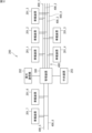
車載システム200は、例えば、車載装置201_1,201_2,201_3,…と、管理装置300と、車外通信機202とを備える。なお、以下の説明では、車載装置201_1,201_2,201_3,…を総称して車載装置201ともいう。
The in-
車載装置201のそれぞれは、例えば、エンジン制御装置、インバータ制御装置、ステアリング制御装置、ブレーキ制御装置、等のパワートレイン及びドライブトレインの制御装置であり、エアコンディショナー制御装置、ナビゲーション装置、表示装置、室内灯制御装置、パワーウインドウ制御装置等の車内設備の制御装置である。
Each of the in-
車載装置201のそれぞれは車載ネットワーク400に接続されている。車載ネットワーク400は複数のCANバスを含む。1つのCANバスは独立したデータ伝送路であり、通信チャンネルである。図2に示す例では、車載ネットワーク400は6つのチャンネル400_1,400_2,400_3,400_4,400_5,400_6を有する。車載装置201のそれぞれは、チャンネル400_1,400_2,400_3,400_4,400_5,400_6の少なくとも1つに接続されている。図2に示す例では、車載装置201_1がチャンネル400_1,400_2に接続され、車載装置201_2がチャンネル400_2,400_3に接続され、車載装置201_3がチャンネル400_1,400_2,400_3,400_4に接続され、車載装置201_4がチャンネル400_3,400_4に接続され、車載装置201_5がチャンネル400_2,400_4に接続され、車載装置201_6,201_7,201_8のそれぞれがチャンネル400_5,400_6に接続されている。
Each of the in-
管理装置300は、車載装置201から要求フレームを受信し、サーバ40にCAN IDの割り当てを要求する。サーバ40からCAN IDが通知されると、管理装置300は割り当てられたCAN IDを含む応答フレームを生成し、要求元の車載装置201へ送信する。つまり、管理装置300は、車載装置201とサーバ40との間を仲介する。
The
管理装置300は、車載ネットワーク400の各チャンネル400_1,400_2,400_3に接続されている。管理装置300は中継装置であり、互いに異なるチャンネルに接続された車載装置201間の通信を中継する。さらに管理装置300は、車載装置201から要求フレームを受信すると、送信元の車載装置201が接続されているチャンネルと、その車載装置201が接続されるべきチャンネルとが一致するか否かを判定する接続状態判定処理を実行する。接続状態が正常である、つまり、車載装置201が正しいチャンネルに接続されている場合、管理装置300は、割り当てられたCAN IDを含む正常応答フレームを生成し、正常応答フレームを要求フレーム送信元の車載装置201へ送信する。他方、車載装置201が正しいチャンネルに接続されていない場合、管理装置300は、CAN IDを含まない異常応答フレームを生成し、異常応答フレームを要求フレーム送信元の車載装置201へ送信する。
The
管理装置300には、車外通信機202が接続されている。車外通信機202は、無線通信を行うことが可能である。車外通信機202は、無線によって基地局20を介して車外の装置、例えば端末、サーバ40等と通信を行う。
An
管理装置300には、中央装置203が接続されている。中央装置203は、ユーザインタフェース、つまり、タッチセンサ、スイッチ、マイクロフォンなどの入力部、及び、モニタ、スピーカ等の出力部を備えている。管理装置300は、ユーザへ異常等を通知する場合、中央装置203に出力指令を送信する。これに応じて、中央装置203が画面又は音声を出力する。
A
[3.管理装置の構成]
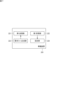
図3は、本実施形態に係る管理装置の構成の一例を示すブロック図である。具体的な一例では、管理装置300は、プロセッサ301と、非一過性メモリ302と、一過性メモリ303と、通信インタフェース304とを備える。
[3. Management device configuration]
FIG. 3 is a block diagram showing an example of the configuration of the management device according to this embodiment. In a specific example, the
一過性メモリ303は、例えばSRAM(Static Random Access Memory)、DRAM(Dynamic Random Access Memory)等の揮発性メモリである。非一過性メモリ302は、例えばフラッシュメモリ、ハードディスク、ROM(Read Only Memory)等の不揮発性メモリである。非一過性メモリ302には、コンピュータプログラムである通信管理プログラム305及び通信管理プログラム305の実行に使用されるデータが格納される。管理装置300は、コンピュータを備えて構成され、管理装置300の各機能は、前記コンピュータの記憶装置に記憶されたコンピュータプログラムである通信管理プログラム305がCPUであるプロセッサ301によって実行されることで発揮される。通信管理プログラム305は、フラッシュメモリ、ROM、CD-ROMなどの記録媒体に記憶させることができる。プロセッサ301は、通信管理プログラム305を実行し、後述するような通信管理処理を実行する。
The
なお、プロセッサ301は、CPUに限られない。プロセッサ301は、例えば、ASIC(Application Specific Integrated Circuit)、ゲートアレイ、FPGA(Field Programmable Gate Array)等のハードウェアロジック回路であってもよい。この場合、ハードウェアロジック回路は、通信管理プログラム305と同様の処理を実行可能に構成される。
Note that the
非一過性メモリ302には、中継テーブル306とチャンネル管理テーブル307とが設けられる。中継テーブル306は、CAN ID毎に使用するチャンネルを管理するためのテーブルである。図4は、中継テーブル306の構成の一例を示す図である。例えば、中継テーブル306において、CAN IDと、フレームの送受信に用いられるチャンネルとが対応付けられている。図4において、“r”は管理装置300がフレームの受信に用いるチャンネルを示し、“s”は管理装置300から車載装置201へのフレームの送信に用いるチャンネルを示している。すなわち、CAN ID“100”を送信元とするフレームの受信用チャンネルの番号が“0”であり、CAN ID“100”を宛先とするフレームの送信用チャンネルの番号が“2”及び“3”である。同様にして、CAN ID“110”を送信元とするフレームの受信用チャンネルの番号が“0”であり、CAN ID“110”を宛先とするフレームの送信用チャンネルの番号が“1”及び“2”である。CAN ID“200”及び“250”を送信元とするフレームの受信用チャンネルの番号が“1”であり、CAN ID“200”及び“250”を宛先とするフレームの送信用チャンネルの番号が“2”である。CAN ID“300”を送信元とするフレームの受信用チャンネルの番号が“2”であり、CAN ID“300”を宛先とするフレームの送信用チャンネルの番号が“4”である。
The
中継テーブル306は、車載装置201と他の装置(例えば、他の車載装置201又は車両10の外部の装置)との間の通信の中継に使用される。例えば1つの車載装置201から、他の車載装置201へCAN ID“100”のCANフレームが送信される場合を考える。このCANフレームにはCAN ID“100”が宛先に含まれる。管理装置300は、チャンネル“0”によってCANフレームを受信し、CANフレームから宛先のCAN ID“100”を抽出する。管理装置300は、中継テーブル306を参照し、CAN ID“100”の送信用チャンネルの番号が“2”及び“3”であることを特定し、選択されたチャンネルにCANフレームを送信する。
The relay table 306 is used to relay communication between the on-
チャンネル管理テーブル307は、上述した接続状態判定処理に用いられる。チャンネル管理テーブル307は、車載装置201の装置IDと、車載装置201が接続されるべきチャンネルとの対応関係を示す対応テーブルである。ここで、「装置ID」とは、車載装置201毎に割り当てられたユニークな識別情報であり、例えば車載装置201のシリアルナンバー、MACアドレス等である。チャンネル管理テーブル307については後述する。
The channel management table 307 is used in the connection state determination process described above. The channel management table 307 is a correspondence table showing the correspondence between the device ID of the in-
通信インタフェース304は車載ネットワーク400の各チャンネル400_1,400_2,400_3及び車外通信機202及び中央装置203と接続される通信線に接続される。
The
[4.車載装置の構成]
図5は、本実施形態に係る車載装置の構成の一例を示すブロック図である。具体的な一例では、車載装置201は、プロセッサ211と、非一過性メモリ212と、一過性メモリ213と、通信インタフェース214とを備える。
[4. Configuration of in-vehicle device]
FIG. 5 is a block diagram showing an example of the configuration of the in-vehicle device according to this embodiment. In one specific example, the in-
非一過性メモリ212には、コンピュータプログラムである通信設定プログラム215及び通信設定プログラム215の実行に使用されるデータが格納される。車載装置201は、コンピュータを備えて構成され、車載装置201のCAN IDの設定に関する機能は、前記コンピュータの記憶装置に記憶されたコンピュータプログラムである通信設定プログラム215がCPUであるプロセッサ211によって実行されることで発揮される。通信設定プログラム215は、フラッシュメモリ、ROM、CD-ROMなどの記録媒体に記憶させることができる。プロセッサ211は、通信設定プログラム215を実行し、後述するような通信設定処理を実行する。さらに非一過性メモリ212には、自装置の装置ID216が記憶されている。
The
なお、プロセッサ211は、CPUに限られない。プロセッサ211は、例えば、ASIC、ゲートアレイ、FPGA等のハードウェアロジック回路であってもよい。この場合、ハードウェアロジック回路は、通信設定プログラム215と同様の処理を実行可能に構成される。
Note that the
通信インタフェース214は車載ネットワーク400のチャンネル400_1,400_2,400_3のうちの1つ又は複数に接続される。
[5.サーバの構成]
図6は、本実施形態に係るサーバの構成の一例を示すブロック図である。具体的な一例では、サーバ40は、プロセッサ401と、非一過性メモリ402と、一過性メモリ403と、通信インタフェース404とを備える。
[5. Server configuration]
FIG. 6 is a block diagram showing an example of the configuration of a server according to this embodiment. In one specific example,
非一過性メモリ402には、コンピュータプログラムであるID割当てプログラム405及びID割当てプログラム405の実行に使用されるデータが格納される。サーバ40は、コンピュータを備えて構成され、サーバ車載装置201用のCAN IDの割当てに関する機能は、前記コンピュータの記憶装置に記憶されたコンピュータプログラムであるID割当てプログラム405がCPUであるプロセッサ401によって実行されることで発揮される。ID割当てプログラム405は、フラッシュメモリ、ROM、CD-ROMなどの記録媒体に記憶させることができる。プロセッサ401は、ID割当てプログラム405を実行し、後述するようなID割当て処理を実行する。
The
非一過性メモリ402には、IDデータベース(以下、「IDDB」という)406が設けられる。IDDB406は、ID割当て処理に用いられる。IDDB406は、車載装置201に割り当てられているCAN IDを車両10毎に管理するためのデータベースである。IDDB406については後述する。
The
[6.車載装置の機能]
次に、車載装置201のCAN IDの設定に関する機能について説明する。図7は、本実施形態に係る車載装置の機能の一例を示す機能ブロック図である。車載装置201は、第1送信部221と、第1受信部222と、要求フレーム生成部223と、設定部224との各機能を有する。
[6. In-vehicle device functions]
Next, functions related to CAN ID setting of the in-
要求フレーム生成部223は、CAN ID付与の要求フレームを生成する。例えば新たな車載装置201が車載ネットワーク400に接続された場合、車載システム200の起動時において、車載装置201はCAN IDの付与を管理装置300に要求する。このとき、要求フレームが生成され、当該要求フレームが管理装置300へ送信される。要求フレーム生成部223は、主としてプロセッサ211によって実現される。
The request
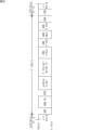
図8は、CANのフレームフォーマットを示す模式図である。図8には、CANの標準フォーマットのデータフレーム構造が示される。図中の上側の線はリセッシブを、下側の線はドミナントを示す。図8に示すように、CANのデータフレームには、SOF(Start Of Frame)、CAN ID、RTR(Remote transmission Request)、コントロールフィールド、データフィールド、CRC(Cyclic Redundancy Check)シーケンス、CRCデリミタ、ACK(Acknowledgement)スロット、ACKデリミタ、EOF(End Of Frame)の各フィールドが含まれる。SOFはフレームの開始を示す。CAN IDは、車載装置201及びフレームの種類を識別するために用いられる。RTRはデータフレームとリモートフレームとを識別するために使用される。データフレームの場合、RTRはドミナントである。コントロールフィールドには通信制御に用いられる情報が格納される。データフィールドには、最大8バイトの実データ(ペイロード)が格納される。CRCシーケンス及びCRCデリミタは合わせてCRCフィールドと呼ばれ、CRCフィールドには一種の誤り検出符号が格納される。ACKスロット及びACKデリミタは合わせてACKフィールドと呼ばれ、ACKフィールドにはCRCフィールド部分までを正常に受信できたか否かを示す情報が格納される。EOFはフレームの終わりを示す。
FIG. 8 is a schematic diagram showing a CAN frame format. FIG. 8 shows the data frame structure of the CAN standard format. The upper line in the figure indicates recessive, and the lower line indicates dominant. As shown in FIG. 8, a CAN data frame includes SOF (Start Of Frame), CAN ID, RTR (Remote transmission Request), control field, data field, CRC (Cyclic Redundancy Check) sequence, CRC delimiter, and ACK ( The field includes an Acknowledgment slot, an ACK delimiter, and an EOF (End Of Frame) field. SOF indicates the start of frame. The CAN ID is used to identify the in-
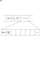
図9は、本実施形態に係る要求フレームの一例を示す模式図である。CAN IDの割当てに関するフレームのCAN IDフィールドには共通ID(例えば、0x6FF)が格納される。共通IDは、CAN IDの割当てに関するフレーム(要求フレーム及び応答フレーム)であることを識別するために用いられる。共通IDは、車載ネットワーク400において共通の情報である。すなわち、車載ネットワーク400に接続された全ての車載装置201及び管理装置300は、CAN IDの割当てに関するフレームを送受信する場合、1つの共通IDを使用する。要求フレームを受信した装置は、CAN IDフィールドの共通IDを参照することによって、当該フレームがCAN IDの割当てに関するフレームであることを識別する。
FIG. 9 is a schematic diagram showing an example of a request frame according to this embodiment. A common ID (for example, 0x6FF) is stored in the CAN ID field of a frame related to CAN ID assignment. The common ID is used to identify frames (request frames and response frames) related to CAN ID assignment. The common ID is information common in the in-
要求フレームのデータフィールドには、「装置ID」及び「要求ID数」の各データが含まれる。1台の車載装置201に割り当てられるCAN IDは1つとは限らず、複数の場合もある。要求ID数は、車載装置201が要求するCAN IDの個数である。要求フレームのデータフィールドの末尾には、当該フレームが要求フレームであることを示す識別子、すなわちCAN IDの要求専用の識別子(図9の例では「00」)が含まれる。要求フレームを受信した装置は、この識別子を参照することによって当該フレームが要求フレームであることを識別する。なお、ここではCANにおける要求フレームの一例を説明したが、要求フレームをCAN FDに適用してもよい。この場合、CAN FDのフレームフォーマットにおけるCAN IDフィールドに共通IDが格納され、データフィールドに「装置ID」及び「要求ID数」が格納される。
The data field of the request frame includes data of "device ID" and "number of request IDs." The number of CAN IDs assigned to one in-
再び図7を参照する。第1送信部221は、要求フレーム生成部223によって生成された要求フレームを、車載装置201に接続されたCANバス(チャンネル)を通じて送信する。第1送信部221は、主として通信インタフェース214によって実現される。
Referring again to FIG. The
管理装置300は、要求フレームに対する応答フレームを送信する。第1受信部222は、車載装置201に接続されたCANバス(チャンネル)を通じて応答フレームを受信する。第1受信部222は、主として通信インタフェース214によって実現される。
The
設定部224は、第1受信部222によって受信された応答フレームが正常応答フレームである場合、当該正常応答フレームに含まれるCAN IDを、自装置のCAN IDとして設定する。自装置のCAN IDは、例えば非一過性メモリ212に記憶される。車載ネットワーク400における以降の通信において、車載装置201を識別する情報としてCAN IDが使用される。設定部224は、主としてプロセッサ211によって実現される。
When the response frame received by the
[7.管理装置の機能]
次に、管理装置300の車載装置201に対するCAN IDの付与に関する機能について説明する。図10は、本実施形態に係る管理装置の機能の一例を示す機能ブロック図である。管理装置300は、第2受信部311と、接続状態判定部312と、ID問合せ部313と、応答フレーム生成部314と、第2送信部315と、出力指令部316との各機能を有する。
[7. Functions of management device]
Next, a function of the
第2受信部311は、車載装置201から送信された要求フレームを、CANバス(チャンネル)を通じて受信する。第2受信部311は、主として通信インタフェース304によって実現される。
The
接続状態判定部312は、第2受信部311によって受信された要求フレームに含まれる固有IDと、要求フレームが伝送されたチャンネルとの対応関係が、チャンネル管理テーブル307に示される対応関係と一致するか否かを判定する。
The connection
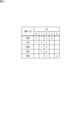
図11は、チャンネル管理テーブルの構成の一例を示す図である。チャンネル管理テーブル307は、車載ネットワーク400のチャンネルの番号と、装置IDの範囲とを対応付けて記憶するテーブルである。図11においては、装置IDが16進数により示されている。図11に示す例では、チャンネル”0”に対して、”0x00”から”0x2F”までの装置IDの範囲が対応する。つまり、装置IDが”0x00”から”0x2F”までの車載装置201の接続先はチャンネル”0”である。同様に、チャンネル”1”には、”0x30”から”0x5F”までの装置IDの範囲が対応する。チャンネル”2”には、”0x60”から”0x8F”までの装置IDの範囲が対応する。チャンネル”3”には、”0x90”から”0xBF”までの装置IDの範囲が対応する。チャンネル”4”には、”0xC0”から”0xEF”までの装置IDの範囲が対応する。
FIG. 11 is a diagram showing an example of the configuration of a channel management table. The channel management table 307 is a table that stores channel numbers of the in-
再び図10を参照する。接続状態判定部312は、要求フレームに含まれる装置IDと、当該要求フレームが伝送されたチャンネルの番号とを、チャンネル管理テーブル307に照会する。つまり、接続状態判定部312は、要求フレームが伝送されたチャンネルの番号に対応する装置IDの範囲をチャンネル管理テーブル307によって特定し、要求フレームに含まれる装置IDが、特定された装置IDの範囲に含まれるか否かを判定する。要求フレームに含まれる装置IDが、特定された装置IDの範囲内である場合、接続状態判定部312は、要求フレームの送信元の車載装置201が、適切なチャンネルに接続されていると判断する。他方、要求フレームに含まれる装置IDが、特定された装置IDの範囲から外れる場合、接続状態判定部312は、要求フレームの送信元の車載装置201が、不適切なチャンネルに接続されていると判断する。接続状態判定部312は、主としてプロセッサ301によって実現される。
Referring again to FIG. The connection
要求フレームに含まれる装置IDが、特定された装置IDの範囲内である場合、ID問合せ部313は、サーバ40へCAN IDの割当てを要求する。さらに具体的には、ID問合せ部313は、要求フレームに含まれる要求ID数分のCAN IDの割当てを要求する。この要求には、要求フレームの送信元の車載装置201の装置IDと、要求ID数とが含まれる。サーバ40は、CAN IDの割当て要求を受け付けると、要求ID数分のCAN IDを割当てる。
If the device ID included in the request frame is within the specified device ID range, the ID inquiry unit 313 requests the
サーバ40によるID割当て処理について説明する。図12は、IDDB406の構成の一例を示す図である。IDDB406は、CAN IDと、装置IDとを対応付けて記憶する。さらにIDDB406は、CAN ID毎に、使用されるチャンネルの番号を記憶する。図12に示す例において、“r”は管理装置300がフレームの受信に用いるチャンネル(受信チャンネル)を示し、“s”は管理装置300から車載装置201へのフレームの送信に用いるチャンネル(送信チャンネル)を示している。すなわち、図12に示されるIDDB406は、ある車載装置201に対してCAN IDが割り当てられた場合に、管理装置300がそのCAN IDを使用して通信するときにフレームをどのチャンネル(受信チャンネル)からどのチャンネル(送信チャンネル)へ中継するかを示している。装置IDに対してCAN IDが割り当てられている場合、IDDB406において当該CAN IDと当該装置IDと送信用チャンネル及び受信用チャンネルの番号とが互いに対応付けて記憶される。図12の例では、CAN ID“100”に対して装置ID“0x10”が登録され、受信用チャンネル “0”及び送信用チャンネル“2”,“3”が登録されている。CAN ID“200”に対して装置ID“0x40”が登録され、受信用チャンネル “1”及び送信用チャンネル“2”が登録されている。CAN ID“250”に対して装置ID“0x50”が登録され、受信用チャンネル “1”及び送信用チャンネル“2”が登録されている。CAN ID“300”に対して装置ID“0x70”が登録され、受信用チャンネル “2”及び送信用チャンネル“4”が登録されている。
ID assignment processing by the
CAN IDが割り当てられていない装置IDは、IDDB406に登録されない。CAN IDに対応する装置IDが存在しない場合、当該CAN IDに対応する装置IDはブランクとされる。図12の例では、CAN ID“210”に対応する装置IDが存在しないため、CAN ID“210”に対する装置IDはブランクとされている。
A device ID to which a CAN ID is not assigned is not registered in the
チャンネル番号に関しては、装置IDに割り当てられていないCAN ID(つまり、利用されていないCAN ID)に対して、送信用チャンネル番号及び受信用チャンネル番号が登録されていない場合と、送信用チャンネル番号及び受信用チャンネル番号が登録されている場合とがある。新たな車載装置201が車載ネットワーク400に接続された場合に、次の2つのケースで管理装置300が使用するチャンネルが決定される。
(1)車載ネットワーク400におけるチャンネルの使用状況を考慮してチャンネルが動的に決定される(以下、「動的チャンネル決定」という)。
(2)CANバスの負荷の偏りを抑制する等の観点から、CAN IDに対して事前にチャンネルが決定されている(以下、「静的チャンネル決定」という)。
具体的な一例では、動的チャンネル決定及び静的チャンネル決定のいずれが用いられるかは、CAN ID毎に定められる。ただし、これに限定されず、全てのCAN IDに対して動的チャンネル決定及び静的チャンネル決定のいずれか一方が用いられてもよい。
Regarding channel numbers, for a CAN ID that is not assigned to a device ID (that is, a CAN ID that is not used), there are two cases in which a sending channel number and a receiving channel number are not registered, and a case in which a sending channel number and a receiving channel number are not registered. In some cases, a reception channel number is registered. When a new in-
(1) A channel is dynamically determined in consideration of the usage status of the channel in the in-vehicle network 400 (hereinafter referred to as "dynamic channel determination").
(2) From the perspective of suppressing load imbalance on the CAN bus, a channel is determined in advance for a CAN ID (hereinafter referred to as "static channel determination").
In one specific example, whether dynamic channel determination or static channel determination is used is determined for each CAN ID. However, the present invention is not limited to this, and either dynamic channel determination or static channel determination may be used for all CAN IDs.
動的チャンネル決定が用いられる場合、IDDB406において、装置IDがブランクとなっているCAN IDに対して(つまり、装置IDがブランクのレコードにおいて)、送信用チャンネル番号及び受信用チャンネル番号が登録されていない。図12の例では、CAN ID“210”に対応する送信用チャンネル及び受信用チャンネルが登録されていない。動的チャンネル決定においては、新たな(つまりCAN IDが割り当てられていない)車載装置201が要求フレームを管理装置300へ送信し、要求フレームを受信した管理装置300が、車載ネットワーク400におけるチャンネルの使用状況(各チャンネルにおける車載装置201の接続数等)に基づいて、当該車載装置201に関する通信(当該車載装置201を宛先又は送信元とする通信)において使用するチャンネルを決定する。管理装置300は、当該車載装置201の装置IDと共に、決定されたチャンネルの番号をサーバ40に通知する。サーバ40は、当該車載装置201に対してCAN IDを割り当て、IDDB406に、CAN IDに対応付けて、装置IDと、受信チャンネル番号及び送信チャンネル番号とを登録する。
When dynamic channel determination is used, in the
他方、静的チャンネル決定が用いられる場合、IDDB406において、装置IDがブランクとなっているCAN IDに対して、送信用チャンネル番号及び受信用チャンネル番号が事前に登録されている。図12の例では、CAN ID“350”に対して事前に受信用チャンネル番号“1”及び送信用チャンネル番号“3”が定められており、CAN ID“350”のレコードにおいて、チャンネル“1”の値が“r”とされ、チャンネル“3”の値が“s”とされる。静的チャンネル決定においては、新たな車載装置201から要求フレームを受信した管理装置300が、サーバ40に当該車載装置201に対するCAN IDを要求すると共に、チャンネルの割り当ても要求する。サーバ40は、当該車載装置201に対してCAN IDを割り当て、IDDB406に、割り当てられたCAN IDに対応付けて装置IDを登録する。さらにサーバ40は、IDDB406を参照して、割り当てられたCAN IDに対して予め定められた受信チャンネル番号及び送信チャンネル番号を特定し、特定された受信チャンネル番号及び送信チャンネル番号を管理装置300へ送信する。
On the other hand, when static channel determination is used, a transmission channel number and a reception channel number are registered in advance in the
再び図10を参照する。ID問合せ部313は、サーバ40から送信されたCAN IDの通知を受信する。ID問合せ部313は、主として通信インタフェース304によって実現される。
Referring again to FIG. The ID inquiry unit 313 receives the CAN ID notification sent from the
応答フレーム生成部314は、第2受信部311によって受信された要求フレームに対して割り当てられたCAN ID、つまり、サーバ40から通知されたCAN IDを含む応答フレーム(正常応答フレーム又は異常応答フレーム)を生成する。具体的には、応答フレーム生成部314は、要求フレームに含まれる装置IDが、特定された装置IDの範囲内である場合、サーバ40によって割り当てられたCAN IDを含む正常応答フレームを生成し、要求フレームに含まれる装置IDが、特定された装置IDの範囲から外れる場合、CAN IDを含まない異常応答フレームを生成する。応答フレーム生成部314は、主としてプロセッサ301によって実現される。
The response
図13は、本実施形態に係る正常応答フレームの一例を示す模式図である。正常応答フレームのCAN IDフィールドには、共通IDが格納される。正常応答フレームのデータフィールドには、「装置ID」及び割り当てられた「CAN ID」の各データが含まれる。具体的には、割り当てられた数のCAN IDがデータフィールドに格納される。正常応答フレームのデータフィールドの末尾には、当該フレームが正常応答フレームであることを示す識別子、すなわち割り当てられたCAN IDの通知専用の識別子(図13の例では「01」)が含まれる。正常応答フレームを受信した装置は、この識別子を参照することによって当該フレームが正常応答フレームであることを識別する。 FIG. 13 is a schematic diagram showing an example of a normal response frame according to this embodiment. A common ID is stored in the CAN ID field of the normal response frame. The data field of the normal response frame includes each data of "device ID" and assigned "CAN ID". Specifically, the assigned number of CAN IDs are stored in the data field. The end of the data field of the normal response frame includes an identifier indicating that the frame is a normal response frame, that is, an identifier (“01” in the example of FIG. 13) exclusively used for notification of the assigned CAN ID. A device that receives a normal response frame identifies that the frame is a normal response frame by referring to this identifier.
図14は、本実施形態に係る異常応答フレームの一例を示す模式図である。異常応答フレームのCAN IDフィールドには、共通IDが格納される。異常応答フレームのデータフィールドには、「装置ID」のデータが含まれる。つまり、異常応答フレームのデータフィールドには、CAN IDが含まれない。異常応答フレームのデータフィールドの末尾には、当該フレームが異常応答フレームであることを示す識別子、すなわちCAN IDの割当てが行われなかったことの通知専用の識別子(図14の例では「FF」)が含まれる。異常応答フレームを受信した装置は、この識別子を参照することによって当該フレームが異常応答フレームであることを識別する。 FIG. 14 is a schematic diagram showing an example of an abnormality response frame according to this embodiment. A common ID is stored in the CAN ID field of the abnormality response frame. The data field of the abnormality response frame includes "device ID" data. In other words, the data field of the abnormal response frame does not include the CAN ID. At the end of the data field of the abnormal response frame, there is an identifier indicating that the frame is an abnormal response frame, that is, an identifier exclusively used to notify that a CAN ID has not been assigned ("FF" in the example of FIG. 14). is included. A device that receives an abnormal response frame identifies that the frame is an abnormal response frame by referring to this identifier.
再び図10を参照する。第2送信部315は、応答フレーム生成部314によって生成された応答フレーム(正常応答フレーム又は異常応答フレーム)を、CAN IDの要求元の車載装置201に接続されたCANバス(チャンネル)を通じて送信する。第2送信部315は、主として通信インタフェース304によって実現される。
Referring again to FIG. The
出力指令部316は、要求フレームに含まれる装置IDが、特定された装置IDの範囲から外れる場合に、エラー出力指令を中央装置203へ送信する。中央装置203(図2参照)は、エラー出力指令を受け付けると、エラー出力を実行する。エラー出力は、例えば、エラー情報の表示、エラー情報の音声出力、ブザー音の出力等である。出力指令部316は、主として通信インタフェース304によって実現される。
The
[8.車載システムの動作]
本実施形態に係る車載システムの動作について説明する。図15は、本実施形態に係る車載装置201の通信設定処理の手順の一例を示すフローチャートであり、図16は、本実施形態に係る管理装置300の通信管理処理の手順の一例を示すフローチャートである。
[8. Operation of in-vehicle system]
The operation of the in-vehicle system according to this embodiment will be explained. FIG. 15 is a flowchart showing an example of a procedure for communication setting processing of the in-
図15を参照する。車載装置201のプロセッサ211は、例えば車載装置201が起動されたとき、又は車載装置201の車載ネットワーク400への接続を検出したときに、通信設定プログラム215(図5参照)を起動する。これにより、プロセッサ211は、通信設定処理を開始する。通信設定処理において、まずプロセッサ211は、自装置に対してCAN IDが設定済みであるか否かを判定する(ステップS101)。この処理では、例えば非一過性メモリ212にCAN IDが記憶されているか否かを判定することにより、CAN IDが設定済みであるか否かが判定される。
See FIG. 15. The
CAN IDが設定済みである場合(ステップS101においてYES)、プロセッサ211は、通信設定処理を終了する。他方、CAN IDが設定されていない場合(ステップS101においてNO)、プロセッサ211は、非一過性メモリ212から装置ID216を読み出す(ステップS102)。さらにプロセッサ211は、読み出された装置ID216を含む要求フレームを生成する(ステップS103)。次いでプロセッサ211は、生成された要求フレームを、車載装置201に接続されているチャンネルを通じて通信インタフェース214に送信させる(ステップS104)。
If the CAN ID has been set (YES in step S101), the
図16を参照する。管理装置300のプロセッサ301は、例えば車載装置201が起動されたときに、通信管理プログラム305(図3参照)を起動する。これにより、プロセッサ301は、通信管理処理を開始する。通信管理処理において、管理装置300は、車載装置201から送信された要求フレームを受信する(ステップS201)。
See FIG. 16. The
次にプロセッサ301は、接続状態判定処理を実行する(ステップS202)。すなわち、プロセッサ301は、要求フレームの送信元の車載装置201の装置IDと、当該車載装置201が接続されているチャンネルとの対応関係が、チャンネル管理テーブル307に登録された装置IDとチャンネルとの対応関係と一致するか否かを判定する。この処理では、要求フレームの送信元の車載装置201の装置IDと、当該車載装置201が接続されているチャンネルとの対応関係が、チャンネル管理テーブル307に登録された装置IDとチャンネルとの対応関係と一致する場合には、装置IDに異常がないと判断され、チャンネル管理テーブル307に登録された装置IDとチャンネルとの対応関係と一致しない場合には、装置IDに異常があると判断される。
Next, the
接続状態判定処理の結果、装置IDに異常がない場合(ステップS202においてYES)、プロセッサ301は、サーバ40にCAN IDの要求を送信する(ステップS203)。サーバ40は、当該要求に応じて装置IDに対してCAN IDを割当て、割り当てられたCAN IDを管理装置300へ通知する。管理装置300は、割り当てられたCAN IDの通知をサーバ40から受信する(ステップS204)。
As a result of the connection state determination process, if there is no abnormality in the device ID (YES in step S202), the
ここで、上述した動的チャンネル決定が用いられる場合、管理装置300が、車載ネットワーク400におけるチャンネルの使用状況に基づいて、新たな車載装置201に関する通信において使用されるチャンネルを決定する。管理装置300は、サーバ40に対するCAN IDの要求において、決定されたチャンネルの番号をサーバ40に通知する。サーバ40は、当該車載装置201に対してCAN IDを割り当て、IDDB406に、CAN IDに対応付けて、装置IDと、受信チャンネル番号及び送信チャンネル番号とを登録する。
Here, when the above-described dynamic channel determination is used, the
静的チャンネル決定が用いられる場合、管理装置300が、サーバ40に新たな車載装置201に対するCAN IDを要求すると共に、チャンネルの割り当ても要求する。サーバ40は、当該車載装置201に対してCAN IDを割り当て、IDDB406に、割り当てられたCAN IDに対応付けて装置IDを登録する。さらにサーバ40は、IDDB406を参照して、割り当てられたCAN IDに対して予め定められた受信チャンネル番号及び送信チャンネル番号を、管理装置300へ送信する。
When static channel determination is used, the
プロセッサ301は、受信したCAN IDを含む正常応答フレームを生成する(ステップS205)。プロセッサ301は、生成された正常応答フレームを、送信対象の車載装置201に接続されているチャンネルを通じて通信インタフェース214に送信させる(ステップS206)。さらにプロセッサ301は、車載装置201に割り当てられたCAN IDを中継テーブル306に登録する(ステップS207)。
The
動的チャンネル決定が用いられる場合、中継テーブル306へのCAN IDの登録の際、プロセッサ301は、決定された送信チャンネル番号及び受信チャンネル番号を、CAN IDに対応付けて登録する。静的チャンネル決定が用いられる場合、中継テーブル306へのCAN IDの登録の際、プロセッサ301は、サーバ40から通知された送信チャンネル番号及び受信チャンネル番号を、CAN IDに対応付けて登録する。以上で、通信管理処理が終了する。
When dynamic channel determination is used, when registering the CAN ID in the relay table 306, the
他方、接続状態判定処理の結果、装置IDに異常がある場合(ステップS202においてNO)、プロセッサ301は、異常応答フレームを生成する(ステップS208)。プロセッサ301は、生成された異常応答フレームを、送信対象の車載装置201に接続されているチャンネルを通じて通信インタフェース214に送信させる(ステップS209)。さらにプロセッサ301は、中央装置203に対してエラー出力指令を通信インタフェース214に送信させる(ステップS210)。以上で、通信管理処理が終了する。
On the other hand, if the result of the connection state determination process is that there is an abnormality in the device ID (NO in step S202), the
再び図15を参照する。要求フレームの送信元の車載装置201は、管理装置300から送信された応答フレーム(正常応答フレーム又は異常応答フレーム)を受信する(ステップS105)。プロセッサ211は、受信された応答フレームが正常応答フレームであるか異常応答フレームであるかを判定する(ステップS106)。すなわち、プロセッサ211は、装置IDに異常があるか、異常がないかを判定する。受信されたフレームが異常応答フレームである場合(ステップS106においてNO)、プロセッサ211は、通信設定処理を中止する。
Referring again to FIG. 15. The in-
他方、受信されたフレームが正常応答フレームである場合(ステップS106においてYES)、プロセッサ211は、受信された正常応答フレームに含まれるCAN IDを自装置のCAN IDとして設定する(ステップS107)。以上で、通信設定処理が終了する。
On the other hand, if the received frame is a normal response frame (YES in step S106), the
[9.変形例]
なお、管理装置300の構成は上述した実施形態に係る管理装置300の構成に限定されない。例えば、サーバ40の機能を管理装置300が有してもよい。つまり、管理装置300が、要求フレームを送信した車載装置201に対してCAN IDを割り当ててもよい。この場合、サーバ40を省略することができる。図17は、実施形態に係る管理装置の機能の変形例を示す機能ブロック図である。図17に示す管理装置300は、ID問合せ部313に代えて、割当て部320の機能を有する。割当て部320は、第2受信部311によって受信された要求フレームに対して、CAN IDを割り当てる。具体的な一例では、割当て部320は、上述したサーバ20と同様のID割当て処理を実行する。
[9. Modified example]
Note that the configuration of the
管理装置300は、要求フレームの送信元の車載装置201の装置IDと、要求フレームが伝送されたチャンネルとの対応関係が、チャンネル管理テーブル307に定義されている対応関係と一致しない場合に、エラー出力指令を中央装置203へ送信する構成について述べたが、これに限定されない。要求フレームの送信元の車載装置201の装置IDと、要求フレームが伝送されたチャンネルとの対応関係が、チャンネル管理テーブル307に定義されている対応関係と一致しない場合に、管理装置300が、エラー情報の表示、エラー情報の音声出力、ブザー音の出力等のエラー出力を行ってもよい。
If the correspondence between the device ID of the in-
要求フレーム及び応答フレームそれぞれのCAN IDフィールドに、共通IDが格納されることとしたが、これに限定されない。要求フレームと応答フレームとでCAN IDフィールドに格納される情報を異ならせてもよい。例えば、要求フレームのCAN IDフィールドには第1共通IDを格納し、応答フレームのCAN IDフィールドには第2共通ID(ただし、第1共通IDと第2共通IDとは互いに異なる)を格納することができる。ここで、第1共通ID及び第2共通IDのそれぞれは、車載ネットワーク400において共通の情報であってもよい。すなわち、車載ネットワーク400に接続された全ての車載装置201及び管理装置300は、要求フレームの送受信には第1共通IDを使用し、応答フレームの送受信には第2共通IDを使用する。要求フレームを受信した装置は、CAN IDフィールドの第1共通IDを参照することによって、当該フレームが要求フレームであることを識別し、応答フレームを受信した装置は、CAN IDフィールドの第2共通IDを参照することによって、当該フレームが応答フレームであることを識別する。
Although the common ID is stored in the CAN ID field of each request frame and response frame, the invention is not limited to this. The information stored in the CAN ID field may be different between the request frame and the response frame. For example, the first common ID is stored in the CAN ID field of the request frame, and the second common ID is stored in the CAN ID field of the response frame (however, the first common ID and the second common ID are different from each other). be able to. Here, each of the first common ID and the second common ID may be common information in the in-
要求フレームに対してCAN IDを割り当てる構成について述べたが、これに限定されるものではない。CAN IDに代えて、CANフレームの拡張フォーマットにおいて定義される拡張IDを用いてもよい。この場合、装置IDを要求フレームのデータフィールドに格納せず、拡張IDを静的に設定して車載装置及び要求フレームを識別する。例えば、拡張IDに装置IDを設定する、もしくはCAN ID及び拡張IDに要求フレームであることを示す車載装置毎に異なるIDを設定する。これにより、データフィールドを参照せずに、CAN ID及び拡張IDからいずれの車載装置からの要求フレームであるかを識別することができる。 Although the configuration in which a CAN ID is assigned to a request frame has been described, the present invention is not limited to this. Instead of the CAN ID, an extension ID defined in the extension format of the CAN frame may be used. In this case, the device ID is not stored in the data field of the request frame, but the extension ID is statically set to identify the in-vehicle device and the request frame. For example, a device ID is set in the extension ID, or a different ID is set in the CAN ID and extension ID for each in-vehicle device indicating that it is a request frame. Thereby, it is possible to identify which in-vehicle device the request frame is from based on the CAN ID and extension ID without referring to the data field.
[10.効果]
以上のように、車載システム200は、車載ネットワーク400に接続される管理装置300と、車載ネットワーク400に接続される車載装置201と、を備える。車載装置201は、第1送信部221と、第1受信部222と、設定部224と、を含む。管理装置300は、第2受信部311と、応答フレーム生成部314と、第2送信部315と、を含む。第1送信部221は、車載装置201の装置ID(固有ID)を含む、CAN ID付与の要求フレームを送信する。第2受信部311は、車載装置201から送信された要求フレームを受信する。応答フレーム生成部314は、第2受信部311によって受信された要求フレームに対して割り当てられたCAN IDを含む応答フレームを生成する。第2送信部315は、応答フレーム生成部314によって生成された応答フレームを、要求フレームの送信元の車載装置201へ送信する。第1受信部222は、管理装置300から送信された応答フレームを受信する。設定部224は、第1受信部222によって受信された応答フレームに含まれるCAN IDを、自装置のCAN IDとして設定する。これにより、車載装置201から送信された要求フレームに応じて、車載装置201とは異なる装置であるサーバ40が、車載装置201間で重複しないようにCAN IDを割り当てることができる。つまり、サーバ40は、各車載装置201に割り当てられるCAN IDを特定し得るため、1つの車載装置201に割り当てられたCAN IDを他の車載装置201に割り当てないようにすることができる。したがって、複数の車載装置201が同時にCAN IDの割り当てを要求したり、1台の車載装置201が複数のCAN IDの割り当てを要求したりする場合に、CAN IDの割り当てに要する時間の増加を抑制することができる。
[10. effect]
As described above, the in-
要求フレームは、要求されたCAN IDの個数(要求ID数)をさらに含んでもよい。応答フレームは、要求ID数の互いに異なるCAN IDを含んでもよい。これにより、1台の車載装置201に対して複数のCAN IDを付与することができる。
The request frame may further include the number of requested CAN IDs (request ID number). The response frame may include a different number of request IDs of CAN IDs. Thereby, multiple CAN IDs can be assigned to one in-
応答フレームは、正常応答フレームと、異常応答フレームとを含んでもよい。応答フレーム生成部314は、CAN IDが割り当てられた場合に、割り当てられたCAN IDを含む正常応答フレームを生成してもよい。応答フレーム生成部314は、CAN IDが割り当てられなかった場合に、CAN IDを含まない異常応答フレームを生成してもよい。第2送信部315は、応答フレーム生成部314によって生成された正常応答フレーム、又は、異常応答フレームを、送信元の車載装置201へ送信してもよい。これにより、車載装置201が正常応答フレームを受信した場合には、車載装置201は正常応答フレームに含まれるCAN IDを取得することができる。車載装置201が異常応答フレームを受信した場合には、車載装置201はCAN IDを取得することなく、再度要求フレームを送信するなど必要な処置を執ることができる。
The response frame may include a normal response frame and an abnormal response frame. When a CAN ID is assigned, the response
管理装置300は、非一過性メモリ302と、接続状態判定部312と、をさらに備えてもよい。非一過性メモリ302は、車載装置201の装置IDと、車載装置201が接続されるCANバスのチャンネルとの対応関係を示すチャンネル管理テーブル307を記憶する。接続状態判定部312は、第2受信部311によって受信された要求フレームに含まれる装置IDと、要求フレームが伝送されたチャンネルとの対応関係が、前記チャンネル管理テーブル307に示される対応関係と一致するか否かを判定する。応答フレーム生成部314は、接続状態判定部312によって、要求フレームに含まれる装置IDと、要求フレームが伝送されたチャンネルとの対応関係が、チャンネル管理テーブル307に示される対応関係と一致すると判定された場合、正常応答フレームを生成する。応答フレーム生成部314は、接続状態判定部312によって、要求フレームに含まれる装置IDと、要求フレームが伝送されたチャンネルとの対応関係が、チャンネル管理テーブル307に示される対応関係と一致しないと判定された場合、異常応答フレームを生成してもよい。これにより、車載装置201が正しいチャンネルに接続されていない場合には、車載装置201にCAN IDを割り当てることなく、異常応答フレームを送信することで接続異常を通知することができる。
The
要求フレームは、車載ネットワーク400において共通の識別情報であり、且つ、CAN IDの割り当て専用の識別情報である共通IDを含んでもよい。CANフレームには、車載装置201のCAN IDを格納するための領域が設けられるが、CAN ID割り当て前の車載装置201は格納すべきCAN IDを有しない。このため、要求フレームに共通IDを格納することにより、車載装置201のCAN IDを必要とせず、要求フレームを受信した管理装置300等の車載装置が当該フレームをCAN IDの割り当てに用いられるフレームとして認識することができる。
The request frame may include a common ID that is common identification information in the in-
要求フレームは、CAN IDの要求専用の識別子をさらに含んでもよい。これにより、要求フレームを受信した管理装置300等の車載装置が、要求フレームと応答フレームとを識別することができる。
The request frame may further include a request-specific identifier for the CAN ID. Thereby, an in-vehicle device such as the
応答フレームは、共通IDを含んでもよい。これにより、応答フレームを受信した車載装置201が当該フレームをCAN IDの割り当てに用いられるフレームとして認識することができる。
The response frame may include a common ID. This allows the in-
応答フレームは、CAN IDの要求に対する応答専用の識別子をさらに含んでもよい。これにより、応答フレームを受信した車載装置201が、要求フレームと応答フレームとを識別することができる。
The response frame may further include an identifier dedicated to responding to the CAN ID request. Thereby, the in-
管理装置300は、第2受信部311によって受信された要求フレームに対してCANIDを割り当てる割当て部をさらに備えてもよい。これにより、管理装置300がサーバなどの外部装置に問い合わせることなく、要求フレームに対してCAN IDを割り当てることができる。
The
要求フレームに用いられるデータ構造は、CAN ID領域と、データ領域とを含む。CAN ID領域には、車載ネットワーク400における共通IDが格納される。データ領域には、CAN IDの割り当てを要求する車載装置201の装置IDと、CAN IDの要求数とが格納される。これにより、要求フレームを受信した管理装置300等の車載装置が、当該フレームを要求フレームとして認識することができ、さらに、必要となるCAN IDの個数を特定することができる。したがって、要求フレームを送信した車載装置201に対して、必要な個数のCAN IDを付与することができる。
The data structure used in the request frame includes a CAN ID field and a data field. A common ID in the in-
応答フレームに用いられるデータ構造は、CAN ID領域と、データ領域とを含む。CAN ID領域には、車載ネットワーク400における共通IDが格納される。データ領域には、CAN IDの割り当てを要求する車載装置201の装置IDと、車載装置201に割り当てられたCAN IDとが格納される。データ領域には、車載装置201から要求された個数のCAN IDが格納される。これにより、応答フレームを受信した車載装置201が、当該フレームを応答フレームとして認識することができ、さらに、1つの車載装置201に対して1又は複数のCAN IDを一度に付与することができる。
The data structure used in the response frame includes a CAN ID area and a data area. A common ID in the in-
[11.補記]
今回開示された実施の形態はすべての点で例示であって、制限的ではない。本発明の権利範囲は、上述の実施形態ではなく特許請求の範囲によって示され、特許請求の範囲と均等の意味及びその範囲内でのすべての変更が含まれる。
[11. Addendum]
The embodiments disclosed this time are illustrative in all respects and are not restrictive. The scope of rights of the present invention is indicated by the claims rather than the above-described embodiments, and includes meanings equivalent to the claims and all changes within the scope.
10 車両
20 基地局
30 インターネット
40 サーバ
100 識別情報管理システム
200 車載システム
201,201_1,201_2,201_3,201_4,201_5,201_6,201_7 車載装置
202 車外通信機
203 中央装置
211 プロセッサ
212 非一過性メモリ
213 一過性メモリ
214 通信インタフェース
215 通信設定プログラム
216 装置ID
221 第1送信部
222 第1受信部
223 要求フレーム生成部
224 設定部
300 管理装置
301 プロセッサ
302 非一過性メモリ
303 一過性メモリ
304 通信インタフェース
305 通信管理プログラム
306 中継テーブル
307 チャンネル管理テーブル
311 第2受信部
312 接続状態判定部
313 ID問合せ部
314 応答フレーム生成部
315 第2送信部
316 出力指令部
320 割当て部
400 車載ネットワーク
400_1,400_2,400_3 チャンネル
401 プロセッサ
402 非一過性メモリ
403 一過性メモリ
404 通信インタフェース
405 プログラム
406 IDデータベース
10
221
Claims (9)
車載装置の固有IDを含む、識別情報付与の要求フレームを前記車載装置から受信する受信部と、
前記受信部によって受信された前記要求フレームに対して割り当てられた識別情報を含む応答フレームを生成する生成部と、
前記生成部によって生成された前記応答フレームを、前記要求フレームの送信元の前記車載装置へ送信する送信部と、
車載装置の固有IDと、車載装置が接続されるネットワークバスのチャンネルとの対応関係を示す対応テーブルを記憶する記憶部と、
前記受信部によって受信された前記要求フレームに含まれる前記固有IDと、前記要求フレームが伝送されたネットワークバスのチャンネルとの対応関係が、前記対応テーブルに示される対応関係と一致するか否かを判定する接続状態判定部と、
を備え、
前記応答フレームは、正常応答フレームと、異常応答フレームとを含み、
前記生成部は、前記接続状態判定部によって、前記要求フレームに含まれる前記固有IDと、前記要求フレームが伝送された前記チャンネルとの対応関係が、前記テーブルに示される前記対応関係と一致すると判定された場合、割り当てられた前記識別情報を含む前記正常応答フレームを生成し、
前記生成部は、前記接続状態判定部によって、前記要求フレームに含まれる前記固有IDと、前記要求フレームが伝送された前記チャンネルとの対応関係が、前記テーブルに示される前記対応関係と一致しないと判定された場合、前記識別情報を含まない前記異常応答フレームを生成する、
管理装置。 A management device that assigns identification information to an in-vehicle device connected to an in-vehicle network,
a receiving unit that receives a request frame for adding identification information, including a unique ID of the in-vehicle device, from the in-vehicle device;
a generation unit that generates a response frame including identification information assigned to the request frame received by the reception unit;
a transmitter that transmits the response frame generated by the generator to the in-vehicle device that is the source of the request frame;
a storage unit that stores a correspondence table indicating a correspondence relationship between a unique ID of an on-vehicle device and a channel of a network bus to which the on-vehicle device is connected;
Determine whether or not the correspondence relationship between the unique ID included in the request frame received by the receiving unit and the channel of the network bus to which the request frame was transmitted matches the correspondence relationship shown in the correspondence table. a connection state determination unit that determines;
Equipped with
The response frame includes a normal response frame and an abnormal response frame,
The generation unit determines, by the connection state determination unit, that the correspondence relationship between the unique ID included in the request frame and the channel to which the request frame was transmitted matches the correspondence relationship shown in the table. if the normal response frame includes the assigned identification information;
The generation unit determines that the connection state determination unit determines that the correspondence relationship between the unique ID included in the request frame and the channel to which the request frame was transmitted does not match the correspondence relationship shown in the table. If determined, generating the abnormal response frame that does not include the identification information;
Management device.
前記応答フレームは、互いに異なる識別情報を前記個数含む、
請求項1に記載の管理装置。 The request frame further includes the number of pieces of requested identification information,
The response frame includes the number of pieces of mutually different identification information.
The management device according to claim 1.
請求項1又は請求項2に記載の管理装置。 The request frame includes common identification information that is common identification information in the in-vehicle network and is identification information dedicated to allocation of identification information.
A management device according to claim 1 or claim 2 .
請求項3に記載の管理装置。 The request frame further includes an identifier dedicated to requesting the identification information.
The management device according to claim 3 .
請求項3又は請求項4に記載の管理装置。 The response frame includes the common identification information,
A management device according to claim 3 or 4 .
請求項5に記載の管理装置。 The response frame further includes an identifier dedicated to responding to the request for identification information.
A management device according to claim 5 .
請求項1から請求項6のいずれか1項に記載の管理装置。 further comprising an assigning unit that assigns identification information to the request frame received by the receiving unit;
A management device according to any one of claims 1 to 6 .
前記車載ネットワークに接続された管理装置が、車載装置の固有IDを含む、識別情報付与の要求フレームを前記車載装置から受信するステップと、
前記管理装置が、受信された前記要求フレームに対して割り当てられた識別情報を含む応答フレームを生成するステップと、
前記管理装置が、生成された前記応答フレームを、前記要求フレームの送信元の前記車載装置へ送信するステップと、
受信された前記要求フレームに含まれる前記固有IDと、前記要求フレームが伝送されたネットワークバスのチャンネルとの対応関係が、前記管理装置において記憶された、車載装置の固有IDと、車載装置が接続されるネットワークバスのチャンネルとの対応関係を示す対応テーブルに示される対応関係と一致するか否かを判定するステップと、
を含み、
前記応答フレームは、正常応答フレームと、異常応答フレームとを含み、
前記要求フレームに含まれる前記固有IDと、前記要求フレームが伝送された前記チャンネルとの対応関係が、前記テーブルに示される前記対応関係と一致すると判定された場合、前記生成するステップにおいて、割り当てられた前記識別情報を含む前記正常応答フレームを生成し、
前記要求フレームに含まれる前記固有IDと、前記要求フレームが伝送された前記チャンネルとの対応関係が、前記テーブルに示される前記対応関係と一致しないと判定された場合、前記生成するステップにおいて、前記識別情報を含まない前記異常応答フレームを生成する、
車載装置の識別情報割り当て方法。 A method for assigning identification information to an in-vehicle device connected to an in-vehicle network, the method comprising:
a step in which a management device connected to the in-vehicle network receives from the in-vehicle device a request frame for providing identification information including a unique ID of the in-vehicle device;
the management device generating a response frame including identification information assigned to the received request frame;
the management device transmitting the generated response frame to the in-vehicle device that is the source of the request frame;
The correspondence relationship between the unique ID included in the received request frame and the channel of the network bus to which the request frame was transmitted is stored in the management device, and the unique ID of the in-vehicle device is connected to the in-vehicle device. a step of determining whether or not the correspondence matches a correspondence shown in a correspondence table showing a correspondence with the network bus channel to be used;
including ;
The response frame includes a normal response frame and an abnormal response frame,
If it is determined that the correspondence relationship between the unique ID included in the request frame and the channel through which the request frame was transmitted matches the correspondence relationship shown in the table, in the generating step, generating the normal response frame including the identification information;
If it is determined that the correspondence relationship between the unique ID included in the request frame and the channel through which the request frame was transmitted does not match the correspondence relationship shown in the table, in the generating step, generating the abnormal response frame that does not include identification information;
A method for assigning identification information to on-vehicle devices.
前記車載ネットワークに接続される車載装置と、
を備え、
前記車載装置は、前記車載装置の固有IDを含む、識別情報付与の要求フレームを送信する第1送信部を含み、
前記管理装置は、
前記車載装置から送信された前記要求フレームを受信する第2受信部と、
前記第2受信部によって受信された前記要求フレームに対して割り当てられた識別情報を含む応答フレームを生成する生成部と、
前記生成部によって生成された前記応答フレームを、前記要求フレームの送信元の前記車載装置へ送信する第2送信部と、
車載装置の固有IDと、車載装置が接続されるネットワークバスのチャンネルとの対応関係を示す対応テーブルを記憶する記憶部と、
前記第2受信部によって受信された前記要求フレームに含まれる前記固有IDと、前記要求フレームが伝送されたネットワークバスのチャンネルとの対応関係が、前記対応テーブルに示される対応関係と一致するか否かを判定する接続状態判定部と、
を含み、
前記車載装置は、
前記管理装置から送信された前記応答フレームを受信する第1受信部と、
前記第1受信部によって受信された前記応答フレームに含まれる識別情報を、自装置の識別情報として設定する設定部と、
をさらに含み、
前記応答フレームは、正常応答フレームと、異常応答フレームとを含み、
前記生成部は、前記接続状態判定部によって、前記要求フレームに含まれる前記固有IDと、前記要求フレームが伝送された前記チャンネルとの対応関係が、前記テーブルに示される前記対応関係と一致すると判定された場合、割り当てられた前記識別情報を含む前記正常応答フレームを生成し、
前記生成部は、前記接続状態判定部によって、前記要求フレームに含まれる前記固有IDと、前記要求フレームが伝送された前記チャンネルとの対応関係が、前記テーブルに示される前記対応関係と一致しないと判定された場合、前記識別情報を含まない前記異常応答フレームを生成する、
車載システム。
A management device connected to the in-vehicle network,
an in-vehicle device connected to the in-vehicle network;
Equipped with
The in-vehicle device includes a first transmitter that transmits a request frame for adding identification information, including a unique ID of the in-vehicle device,
The management device includes:
a second receiving unit that receives the request frame transmitted from the in-vehicle device;
a generating unit that generates a response frame including identification information assigned to the request frame received by the second receiving unit;
a second transmitting unit that transmits the response frame generated by the generating unit to the in-vehicle device that is the source of the request frame;
a storage unit that stores a correspondence table indicating a correspondence relationship between a unique ID of the in-vehicle device and a channel of a network bus to which the in-vehicle device is connected;
Whether the correspondence relationship between the unique ID included in the request frame received by the second receiving unit and the channel of the network bus to which the request frame was transmitted matches the correspondence relationship shown in the correspondence table. a connection state determination unit that determines whether the
including;
The in-vehicle device includes:
a first receiving unit that receives the response frame transmitted from the management device;
a setting unit that sets identification information included in the response frame received by the first receiving unit as identification information of the own device;
further including ;
The response frame includes a normal response frame and an abnormal response frame,
The generation unit determines, by the connection state determination unit, that the correspondence relationship between the unique ID included in the request frame and the channel to which the request frame was transmitted matches the correspondence relationship shown in the table. if the normal response frame includes the assigned identification information;
The generation unit determines that the connection state determination unit determines that the correspondence relationship between the unique ID included in the request frame and the channel to which the request frame was transmitted does not match the correspondence relationship shown in the table. If determined, generating the abnormal response frame that does not include the identification information;
In-vehicle system.
Priority Applications (4)
| Application Number | Priority Date | Filing Date | Title |
|---|---|---|---|
| JP2020007269A JP7363510B2 (en) | 2020-01-21 | 2020-01-21 | Management device, identification information assignment method for in-vehicle devices, in-vehicle system, and data structure |
| US17/759,084 US11923999B2 (en) | 2020-01-21 | 2021-01-12 | Management apparatus, method for allocating identification information of onboard apparatus, onboard system, and data structure |
| CN202180007918.7A CN114902614A (en) | 2020-01-21 | 2021-01-12 | Management device, identification information distribution method for in-vehicle device, in-vehicle system, and data structure |
| PCT/JP2021/000687 WO2021149537A1 (en) | 2020-01-21 | 2021-01-12 | Management device, method for allocating identification information of on-vehicle device, on-vehicle system, and data structure |
Applications Claiming Priority (1)
| Application Number | Priority Date | Filing Date | Title |
|---|---|---|---|
| JP2020007269A JP7363510B2 (en) | 2020-01-21 | 2020-01-21 | Management device, identification information assignment method for in-vehicle devices, in-vehicle system, and data structure |
Publications (3)
| Publication Number | Publication Date |
|---|---|
| JP2021114724A JP2021114724A (en) | 2021-08-05 |
| JP2021114724A5 JP2021114724A5 (en) | 2022-05-18 |
| JP7363510B2 true JP7363510B2 (en) | 2023-10-18 |
Family
ID=76992254
Family Applications (1)
| Application Number | Title | Priority Date | Filing Date |
|---|---|---|---|
| JP2020007269A Active JP7363510B2 (en) | 2020-01-21 | 2020-01-21 | Management device, identification information assignment method for in-vehicle devices, in-vehicle system, and data structure |
Country Status (4)
| Country | Link |
|---|---|
| US (1) | US11923999B2 (en) |
| JP (1) | JP7363510B2 (en) |
| CN (1) | CN114902614A (en) |
| WO (1) | WO2021149537A1 (en) |
Families Citing this family (1)
| Publication number | Priority date | Publication date | Assignee | Title |
|---|---|---|---|---|
| CN115314155B (en) * | 2022-07-14 | 2024-01-09 | 东风电驱动系统有限公司 | Communication method, device, equipment and readable storage medium |
Citations (6)
| Publication number | Priority date | Publication date | Assignee | Title |
|---|---|---|---|---|
| JP2006090038A (en) | 2004-09-24 | 2006-04-06 | Denso Corp | On-vehicle system and id allotment method |
| JP2012048424A (en) | 2010-08-25 | 2012-03-08 | Nippon Telegr & Teleph Corp <Ntt> | Method and program for allocating identifier |
| JP2012222527A (en) | 2011-04-06 | 2012-11-12 | Toyota Motor Corp | In-vehicle network, management node, and number assignment method |
| JP2015179375A (en) | 2014-03-19 | 2015-10-08 | 株式会社デンソー | Program rewrite system and electronic control unit |
| JP2017091049A (en) | 2015-11-05 | 2017-05-25 | 株式会社リコー | Access control system, access control method, and access control program |
| WO2018105330A1 (en) | 2016-12-06 | 2018-06-14 | パナソニック インテレクチュアル プロパティ コーポレーション オブ アメリカ | Information processing method, information processng system, and program |
Family Cites Families (4)
| Publication number | Priority date | Publication date | Assignee | Title |
|---|---|---|---|---|
| JP5007315B2 (en) * | 2009-04-03 | 2012-08-22 | 本田技研工業株式会社 | In-vehicle gateway device |
| KR101742951B1 (en) * | 2015-04-15 | 2017-06-02 | 주식회사 다산네트웍스 | Network switch with MAC/IP assignment protocol |
| US10454887B2 (en) * | 2015-11-18 | 2019-10-22 | Cisco Technology, Inc. | Allocation of local MAC addresses to client devices |
| JP2020191614A (en) * | 2019-05-24 | 2020-11-26 | パナソニックIpマネジメント株式会社 | Information processor, information processing method and program |
-
2020
- 2020-01-21 JP JP2020007269A patent/JP7363510B2/en active Active
-
2021
- 2021-01-12 US US17/759,084 patent/US11923999B2/en active Active
- 2021-01-12 WO PCT/JP2021/000687 patent/WO2021149537A1/en active Application Filing
- 2021-01-12 CN CN202180007918.7A patent/CN114902614A/en active Pending
Patent Citations (6)
| Publication number | Priority date | Publication date | Assignee | Title |
|---|---|---|---|---|
| JP2006090038A (en) | 2004-09-24 | 2006-04-06 | Denso Corp | On-vehicle system and id allotment method |
| JP2012048424A (en) | 2010-08-25 | 2012-03-08 | Nippon Telegr & Teleph Corp <Ntt> | Method and program for allocating identifier |
| JP2012222527A (en) | 2011-04-06 | 2012-11-12 | Toyota Motor Corp | In-vehicle network, management node, and number assignment method |
| JP2015179375A (en) | 2014-03-19 | 2015-10-08 | 株式会社デンソー | Program rewrite system and electronic control unit |
| JP2017091049A (en) | 2015-11-05 | 2017-05-25 | 株式会社リコー | Access control system, access control method, and access control program |
| WO2018105330A1 (en) | 2016-12-06 | 2018-06-14 | パナソニック インテレクチュアル プロパティ コーポレーション オブ アメリカ | Information processing method, information processng system, and program |
Also Published As
| Publication number | Publication date |
|---|---|
| JP2021114724A (en) | 2021-08-05 |
| US11923999B2 (en) | 2024-03-05 |
| US20230058027A1 (en) | 2023-02-23 |
| CN114902614A (en) | 2022-08-12 |
| WO2021149537A1 (en) | 2021-07-29 |
Similar Documents
| Publication | Publication Date | Title |
|---|---|---|
| KR102360168B1 (en) | Apparatus and method for converting protocol with type of data | |
| KR101630729B1 (en) | Method and System for Providing Optimized Ethernet Communication for vehicle | |
| US8233424B2 (en) | Wireless communication system, connection device, relay device and registering method | |
| KR100689734B1 (en) | method and apparatus for allocating address in wireless network | |
| US20080028071A1 (en) | Communication load reducing method and computer system | |
| US8677019B2 (en) | Data communication method using unambiguous vehicle identification information | |
| JP2006514456A (en) | Priority transmission of data stream | |
| CN107249048B (en) | Air conditioning system and address allocation method and device thereof | |
| US20150113168A1 (en) | Network Bridging | |
| KR20200136751A (en) | Apparatus for communicating diagnosis of a vehicle, system having the same and method thereof | |
| JP2012222527A (en) | In-vehicle network, management node, and number assignment method | |
| JPWO2007072554A1 (en) | Address assignment device | |
| Talbot et al. | Comparision of fieldbus systems can, ttcan, flexray and lin in passenger vehicles | |
| JP7363510B2 (en) | Management device, identification information assignment method for in-vehicle devices, in-vehicle system, and data structure | |
| WO2013001641A1 (en) | Ip address delivery system | |
| CN108600411B (en) | Method and device for allocating train addresses, train equipment and storage medium | |
| CN103825789A (en) | Bus system, method for operating bus system and fluid system with bus system | |
| CN106302845A (en) | The Domain Name System addresses collocation method of data channel product and device | |
| JP4019666B2 (en) | Gateway device and information device | |
| KR101742951B1 (en) | Network switch with MAC/IP assignment protocol | |
| CN109561170B (en) | Address pool creating method and device, address pool management system and storage medium | |
| KR100766066B1 (en) | Dynamic Service Allocation Gateway System and the Method for Plug?Play in the Ubiquitous environment | |
| Ditze et al. | Porting the internet protocol to the controller area network | |
| KR100687746B1 (en) | Method and apparatus for preventing collision of address | |
| EP4304136A1 (en) | Control area network devices and method |
Legal Events
| Date | Code | Title | Description |
|---|---|---|---|
| A521 | Request for written amendment filed |
Free format text: JAPANESE INTERMEDIATE CODE: A523 Effective date: 20220510 |
|
| A621 | Written request for application examination |
Free format text: JAPANESE INTERMEDIATE CODE: A621 Effective date: 20220523 |
|
| A131 | Notification of reasons for refusal |
Free format text: JAPANESE INTERMEDIATE CODE: A131 Effective date: 20230425 |
|
| A521 | Request for written amendment filed |
Free format text: JAPANESE INTERMEDIATE CODE: A523 Effective date: 20230614 |
|
| A131 | Notification of reasons for refusal |
Free format text: JAPANESE INTERMEDIATE CODE: A131 Effective date: 20230718 |
|
| A521 | Request for written amendment filed |
Free format text: JAPANESE INTERMEDIATE CODE: A523 Effective date: 20230825 |
|
| TRDD | Decision of grant or rejection written | ||
| A01 | Written decision to grant a patent or to grant a registration (utility model) |
Free format text: JAPANESE INTERMEDIATE CODE: A01 Effective date: 20230905 |
|
| A61 | First payment of annual fees (during grant procedure) |
Free format text: JAPANESE INTERMEDIATE CODE: A61 Effective date: 20230918 |
|
| R150 | Certificate of patent or registration of utility model |
Ref document number: 7363510 Country of ref document: JP Free format text: JAPANESE INTERMEDIATE CODE: R150 |