JP7363432B2 - filling nozzle - Google Patents
filling nozzle Download PDFInfo
- Publication number
- JP7363432B2 JP7363432B2 JP2019220203A JP2019220203A JP7363432B2 JP 7363432 B2 JP7363432 B2 JP 7363432B2 JP 2019220203 A JP2019220203 A JP 2019220203A JP 2019220203 A JP2019220203 A JP 2019220203A JP 7363432 B2 JP7363432 B2 JP 7363432B2
- Authority
- JP
- Japan
- Prior art keywords
- filling
- nozzle body
- valve
- vertical cylindrical
- rod
- Prior art date
- Legal status (The legal status is an assumption and is not a legal conclusion. Google has not performed a legal analysis and makes no representation as to the accuracy of the status listed.)
- Active
Links
Images


Description
本発明は、充填ノズルに関するものである。特に自動充填機に用いられ、その充填動作において、充填ノズルの内圧が安定し、液はねなど充填時の内圧の変動に起因する不具合を起こすことのない充填ノズルに関するものである。 FIELD OF THE INVENTION The present invention relates to a filling nozzle. In particular, the present invention relates to a filling nozzle that is used in an automatic filling machine, in which the internal pressure of the filling nozzle is stable during the filling operation, and does not cause problems such as liquid splashing due to fluctuations in the internal pressure during filling.
今日、自動充填機は、幅広い分野で使われており、液体や流体を定量かつ効率よく充填することを目的として、例えば食品や飲料などの用途に広く使われている。 Today, automatic filling machines are used in a wide range of fields, and are widely used in applications such as food and beverages, for the purpose of filling liquids and fluids quantitatively and efficiently.
さらに、単なる液体に限らず加工食品などにおいても使われており、充填液の種類も固形物を含有した液体など多彩で、用途に合わせた自動充填機が開発され、使われている。 Furthermore, it is used not only for simple liquids but also for processed foods, etc., and the types of filling liquids are diverse, including liquids containing solids, and automatic filling machines tailored to the purpose have been developed and used.
自動充填機の被充填容器側の先端部は、充填機先端ノズルとなっており、容器の口部から、あるいは容器の内部に深く差し入れて充填を行う。 The tip of the automatic filling machine on the side of the container to be filled is a filling machine tip nozzle, and filling is performed from the mouth of the container or by inserting it deeply into the container.
したがって、充填ノズルは上下に延びるパイプ形状をしているものが一般的であり、充填液の流量を調整するピストンシリンダーや、吐出量を制御するバルブなどを備えている。 Therefore, the filling nozzle generally has a pipe shape that extends vertically, and is equipped with a piston cylinder that adjusts the flow rate of the filling liquid, a valve that controls the discharge amount, and the like.
例えば、特許文献1には流体のほか、固形物を含有した液体や、ゼリー状の液体に適しているとされる充填ノズルが提案されている。 For example, Patent Document 1 proposes a filling nozzle that is said to be suitable for not only fluids but also liquids containing solids and jelly-like liquids.
この充填ノズルの場合には充填シリンダーおよび充填ピストンを有して、ピストンの前進後退によって、定量の充填液を充填ノズル内に送り込んで、容器に充填する仕組みをとっている。 This filling nozzle has a filling cylinder and a filling piston, and by advancing and retracting the piston, a fixed amount of filling liquid is sent into the filling nozzle to fill the container.
しかしながらこの方式は、充填ノズル内のバルブの開閉によって、充填液の流体の吐出を制御しようとするものであって、充填ピストンの押量と充填液の流体の重力落下のわずかなタイミングのギャップによる、充填ノズル内部の圧力の変動が生じる結果となっている。 However, this method attempts to control the discharge of the filling liquid by opening and closing the valve in the filling nozzle, and is based on the slight timing gap between the amount of push of the filling piston and the gravity fall of the filling liquid. , resulting in pressure fluctuations inside the filling nozzle.
さらにこの不安定要因によって、充填液の流体の層流化を阻害する恐れもあり、液ハネ、液チリ、液トビなどの不具合を引き起こす一因となっている。 Furthermore, this unstable factor may impede the laminar flow of the filling liquid, which is one of the causes of problems such as liquid splashing, liquid dust, and liquid splatter.
本発明は、かかる状況に鑑みてなされたものであり、充填ノズルによる充填に際して、ノズル内の内圧の変動が少なく、安定した充填を可能とする充填ノズルの提供を課題とする。 The present invention has been made in view of this situation, and an object of the present invention is to provide a filling nozzle that allows stable filling with little variation in the internal pressure within the nozzle.
上記の課題を解決するための手段として、請求項1に記載の発明は、
自動充填機の充填ノズルであって、
充填ノズルは、定量計量充填部、および垂直筒状ノズル本体、弁部材からなり
前記定量計量充填部は、充填シリンダー、充填ピストン、および吸引差圧バルブとからなり、充填ピストンの押し込みによって、中空パイプで接続する垂直筒状ノズル本体に充填液を供給することができ、
前記垂直筒状ノズル本体は中空であって、下方先端は被充填容器に向かう吐出口となっており、
前記垂直筒状ノズル本体の中間には内側にリング形状のバルブ当てが設けてあり、
前記弁部材は、垂直筒状ノズル本体の内部に、吐出バルブ、および充填先端バルブを有し、垂直筒状ノズル本体の上部外側にラック・ピニオン機構を有して構成されており、
前記吐出バルブは、垂直筒状ノズル本体を内側から上部外側にかけて貫くロッド1を有して上下に可動であり、ノズル本体内側において上方に移動してリング形状のバルブ当て下側に密着して閉、下方に移動して開とすることができ、
前記リング形状のバルブ当ての上側には、吐出バルブに連続するロッド1を下方から支えて、吐出バルブの上面をリング形状のバルブ当てに密着させて閉とすることのできるスプリングが備えてあり、
前記充填先端バルブは、垂直筒状ノズル本体を内側から上部外側にかけて貫くロッド2を有して上下に可動であり、ノズル本体内側において下方に移動して吐出口に密着して閉、上方に移動して開とすることができ、
ロッド1、およびロッド2の上部は、垂直筒状ノズル本体の上部外側の部分に棒状のラックが連続しており、
ラックには、ピニオンギヤと噛み合うギヤが直線状に刻まれており、
前記ラック・ピニオン機構は、前記垂直筒状ノズル本体の上部外側に位置して、ロッド1、およびロッド2が、ピニオンギヤを介して対向して配置されていることを特徴とする自動充填機の充填ノズル
である。
As a means for solving the above problem, the invention according to claim 1 is as follows:
A filling nozzle for an automatic filling machine,
The filling nozzle consists of a quantitative metering filling part, a vertical cylindrical nozzle body, and a valve member. The quantitative metering filling part consists of a filling cylinder, a filling piston, and a suction differential pressure valve. The filling liquid can be supplied to the vertical cylindrical nozzle body connected with the
The vertical cylindrical nozzle body is hollow, and the lower tip serves as a discharge port toward the container to be filled,
A ring-shaped valve stopper is provided inside the vertical cylindrical nozzle body in the middle,
The valve member has a discharge valve and a filling tip valve inside a vertical cylindrical nozzle body, and has a rack and pinion mechanism on the outside of the upper part of the vertical cylindrical nozzle body,
The discharge valve has a rod 1 that passes through the vertical cylindrical nozzle body from the inside to the upper outside, and is movable up and down.The discharge valve moves upward inside the nozzle body and closes by coming into close contact with the lower side of the ring-shaped valve stopper. , can be moved downward and opened,
A spring is provided above the ring-shaped valve stopper to support the rod 1 connected to the discharge valve from below and close the top surface of the discharge valve by bringing the top surface of the discharge valve into close contact with the ring-shaped valve stopper.
The filling tip valve has a
The upper part of the rod 1 and the
The rack has a straight gear carved into it that engages with the pinion gear.
The rack and pinion mechanism is located outside the upper part of the vertical cylindrical nozzle body, and a rod 1 and a
本発明によれば、充填ノズルによる充填に際して、ノズル内の内圧の変動が少なく、安定した充填を可能とする充填ノズルの提供が可能である。 According to the present invention, it is possible to provide a filling nozzle that allows stable filling with little variation in the internal pressure within the nozzle during filling.
すなわち、従来の充填ノズルは充填を開始するに際して、ピストンが作動する前に先端バルブが開くようになっており、充填液が自重で落下し、ピストンで押し出す容量よりも多くの落下液がある。このため充填ノズル内は一瞬負圧になる。 That is, when a conventional filling nozzle starts filling, the tip valve opens before the piston operates, and the filling liquid falls under its own weight, and there is more liquid falling than the volume pushed out by the piston. Therefore, the inside of the filling nozzle momentarily becomes negative pressure.
その後ピストンの押し出し量は落下量を上回り充填ノズル内は陽圧に転じる。この一連の動作に伴う圧力の不安定が生じ、この不安定要因によって、充填液の流体の層流化を阻害する恐れもあり、液ハネ、液チリ、液トビなどの不具合を引き起こす一因ともなっている。 After that, the amount of piston extrusion exceeds the amount of fall, and the inside of the filling nozzle becomes positive pressure. Pressure instability occurs due to this series of operations, and this unstable factor may impede the laminar flow of the filling liquid, and may also be a contributing factor to problems such as liquid splashing, liquid dust, and liquid splatter. ing.
これに対し、本発明による充填バルブにおいては、先端に押し付けて充填を完了する形式の充填先端ノズルを有し、また充填ノズルの内圧によって開く吐出バルブを設けてあり、これらがラック・ピニオン機構によって連動して開閉する構造であるために、ノズル内の内圧の変動が少なく、安定した充填を実現することのできる充填ノズルを提供することが可能である。 In contrast, the filling valve according to the present invention has a filling tip nozzle that is pressed against the tip to complete filling, and is also provided with a discharge valve that opens due to the internal pressure of the filling nozzle, which is operated by a rack and pinion mechanism. Since the nozzle has a structure that opens and closes in conjunction with each other, it is possible to provide a filling nozzle that can realize stable filling with little fluctuation in the internal pressure within the nozzle.
また、これらの開閉はエアーシリンダーを使わずに、本発明においては機械式反転駆動であるため、エアーシリンダーのほか、電磁弁、配線、配管が不要であるため、より簡素の構造が実現でき、したがって故障の恐れも軽減され、安価な充填バルブとすることができる。 In addition, these openings and closings do not use an air cylinder, but instead use a mechanical reversal drive in the present invention, so in addition to an air cylinder, solenoid valves, wiring, and piping are not required, so a simpler structure can be realized. Therefore, the possibility of failure is reduced, and an inexpensive filling valve can be obtained.
以下、本発明を図1~図6を参照しながら、更に詳しい説明を加える。ただし本発明は、ここに示す例にのみ限定されるものではない。本発明は、請求項によって限定されるものである。 The present invention will be described in more detail below with reference to FIGS. 1 to 6. However, the present invention is not limited to the examples shown here. The invention is limited by the claims.
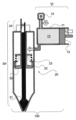
図1は、本発明に係る充填ノズルの一実施態様を説明するための、断面模式図である。 FIG. 1 is a schematic cross-sectional view for explaining one embodiment of a filling nozzle according to the present invention.
本発明は、充填ノズル(100)に関するものであって、特に液体や流体の自動充填機の充填ノズル(100)に関するものである。 The present invention relates to a filling nozzle (100), and particularly to a filling nozzle (100) for an automatic liquid or fluid filling machine.
本発明による充填ノズル(100)は、定量計量充填部(10)、および垂直筒状ノズル本体(20)、弁部材(30)から構成される。 The filling nozzle (100) according to the invention is composed of a quantitative filling part (10), a vertical cylindrical nozzle body (20), and a valve member (30).
定量計量充填部(10)は、充填シリンダー(11)、充填ピストン(12)、および吸引差圧バルブ(14)とからなり、充填ピストン(12)の充填シリンダー(11)への押し込みによって、垂直筒状ノズル本体(20)に定量の充填液を供給することができる。 The quantitative metering filling section (10) consists of a filling cylinder (11), a filling piston (12), and a suction differential pressure valve (14), and is vertically moved by pushing the filling piston (12) into the filling cylinder (11). A fixed amount of filling liquid can be supplied to the cylindrical nozzle body (20).
充填液は、充填ピストン(12)の動きによって、例えば充填シリンダー(11)内が負圧になったときには、吸引差圧バルブ(14)は開いた状態となって、充填液は矢印(1)の方向に流れて、充填シリンダー(11)内に吸引される。これは充填ピストン(12)が充填シリンダー(11)に対して引き出される方向の動きによって引き起こされるものである。 For example, when the inside of the filling cylinder (11) becomes negative pressure due to the movement of the filling piston (12), the suction differential pressure valve (14) is opened and the filling liquid flows as indicated by the arrow (1). and is sucked into the filling cylinder (11). This is caused by the movement of the filling piston (12) in the withdrawing direction relative to the filling cylinder (11).
逆に充填シリンダー(11)内が陽圧になったときには、吸引差圧バルブ(14)は閉じた状態となって、充填液は矢印(2)方向に押し出されて、垂直筒状ノズル本体(20)内に供給される。これは充填ピストン(12)が充填シリンダー(11)に対して押し込みの方向の動きによって引き起こされるものである。 Conversely, when the inside of the filling cylinder (11) becomes positive pressure, the suction differential pressure valve (14) is closed and the filling liquid is pushed out in the direction of the arrow (2) and flows through the vertical cylindrical nozzle body ( 20). This is caused by the movement of the filling piston (12) in the pushing direction relative to the filling cylinder (11).
また、連続した充填を行う自動充填機においては、充填ピストン(12)の動きの距離と速度を一定にすることによって、充填液の定量計量、および垂直筒状ノズル本体(20)内への供給を安定して行うことができる。 In addition, in an automatic filling machine that performs continuous filling, by keeping the distance and speed of movement of the filling piston (12) constant, it is possible to quantitatively measure the filling liquid and supply it into the vertical cylindrical nozzle body (20). can be performed stably.
垂直筒状ノズル本体(20)は中空、縦長のパイプ形状であって、その下方先端部分は被充填容器に向かう充填口(21)となっており、垂直筒状ノズル本体(20)の中間部分には、内側にリング形状のバルブ当て(22)が設けてある。 The vertical cylindrical nozzle body (20) has a hollow, vertically elongated pipe shape, and its lower tip portion serves as a filling port (21) facing the container to be filled, and the middle portion of the vertical cylindrical nozzle body (20) is provided with a ring-shaped valve pad (22) inside.
リング形状のバルブ当て(22)の上側には、スプリング(23)が備えてある。但し、スプリング(23)の作用については、後述の弁部材(30)の説明に含める。 A spring (23) is provided above the ring-shaped valve stopper (22). However, the action of the spring (23) will be included in the explanation of the valve member (30) below.
弁部材(30)は、吐出バルブ(32)、および充填先端バルブ(31)、およびラック・ピニオン機構(33)とからなる。 The valve member (30) consists of a discharge valve (32) and a fill tip valve (31) and a rack and pinion mechanism (33).
吐出バルブ(32)は、下端において円盤形状であって、垂直筒状ノズル本体(20)を内側で貫くロッド1(34)を有して上下に可動である。またロッド1(34)は円筒形であって、内側にロッド2(35)が配置され、それぞれは独立して上下に動くことが可能な構造である。ロッド2(35)については、充填先端バルブ(31)の説明において後述する。 The discharge valve (32) is disk-shaped at its lower end and has a rod 1 (34) that penetrates the vertical cylindrical nozzle body (20) inside and is movable up and down. The rod 1 (34) has a cylindrical shape, and the rods 2 (35) are arranged inside the rod 1 (34), each of which can move up and down independently. Rod 2 (35) will be described later in the description of the filling tip valve (31).
この吐出バルブ(32)、およびそれに連続するロッド1(34)上下の動きによって、ロッド1(34)が垂直筒状ノズル本体(20)内側において上方に移動した場合には、吐出バルブ(32)は、リング形状のバルブ当て(22)下部に密着して、吐出バルブ(32)の状態を閉じた状態とすることができる。 When the rod 1 (34) moves upward inside the vertical cylindrical nozzle body (20) due to the vertical movement of the discharge valve (32) and the rod 1 (34) that continues therewith, the discharge valve (32) can be brought into close contact with the lower part of the ring-shaped valve pad (22) to keep the discharge valve (32) in a closed state.
すなわち、吐出バルブ(32)の円盤形状の部分の上面と、リング形状のバルブ当て(22)の下部とが密着した状態である。この状態は、垂直筒状ノズル本体(20)内側において、垂直筒状ノズル本体(20)の上部と下部とが、吐出バルブ(32)によって仕切られている状態である。 That is, the upper surface of the disc-shaped portion of the discharge valve (32) and the lower part of the ring-shaped valve pad (22) are in close contact with each other. In this state, the upper and lower parts of the vertical cylindrical nozzle body (20) are partitioned off by the discharge valve (32) inside the vertical cylindrical nozzle body (20).
逆にロッド1(34)が垂直筒状ノズル本体(20)内側において、下方に移動した場合には、リング形状のバルブ当て(22)下部との間に間隙ができるために、吐出バルブ(32)の状態を開いた状態とすることができる。 Conversely, if the rod 1 (34) moves downward inside the vertical cylindrical nozzle body (20), a gap is created between the lower part of the ring-shaped valve pad (22) and the discharge valve (32) moves downward. ) can be set to an open state.
すなわち、吐出バルブ(32)が開いた状態であるときには、垂直筒状ノズル本体(20)内側において、垂直筒状ノズル本体(20)の上部と下部とが、ひと続きになっている状態である。 That is, when the discharge valve (32) is in the open state, the upper and lower parts of the vertical cylindrical nozzle body (20) are in a continuous state inside the vertical cylindrical nozzle body (20). .
リング形状のバルブ当て(22)の上側には、吐出バルブ(32)に連続するロッド1(34)を下方から上向きに支えて、吐出バルブ(32)をリング形状のバルブ当て(22)に密着させることのできるスプリング(23)が備えてある。 On the upper side of the ring-shaped valve pad (22), the rod 1 (34) that is continuous with the discharge valve (32) is supported upward from below, and the discharge valve (32) is tightly attached to the ring-shaped valve pad (22). A spring (23) is provided that can be moved.
そのため、垂直筒状ノズル本体(20)の内部の圧力が一定の圧力以下の状態においては、スプリング(23)の上方への反発力によって、吐出バルブ(32)を閉じた状態にしておくことが可能である。 Therefore, when the internal pressure of the vertical cylindrical nozzle body (20) is below a certain level, the discharge valve (32) cannot be kept closed by the upward repulsive force of the spring (23). It is possible.
一方、充填先端バルブ(31)は、垂直筒状ノズル本体(20)を内側で貫くロッド2(35)を有して上下に可動である。ロッド2(35)は、ロッド1(34)の円筒形の内側に位置するように設けてあり、それらの上下の動きは、それぞれ独立して行うことが可能である。 On the other hand, the filling tip valve (31) has a rod 2 (35) that penetrates the vertical cylindrical nozzle body (20) inside and is movable up and down. The rod 2 (35) is provided so as to be located inside the cylindrical shape of the rod 1 (34), and their vertical movements can be performed independently.
この上下の動きによって、ロッド2(35)が垂直筒状ノズル本体(20)内側において下方に移動した場合には、充填先端バルブ(31)は充填口(21)に密着して、充填先端バルブ(31)の状態を閉じた状態とすることができる。すなわち充填口(21)が
閉じられた状態である。
When the rod 2 (35) moves downward inside the vertical cylindrical nozzle body (20) due to this vertical movement, the filling tip valve (31) comes into close contact with the filling port (21), and the filling tip valve The state (31) can be made into a closed state. That is, the filling port (21) is in a closed state.
逆にロッド2(35)が垂直筒状ノズル本体(20)内側において、上方に移動した場合には、充填口(21)との間に間隙ができるために、充填先端バルブ(31)の状態を開いた状態とすることができる。この状態において、充填口(21)からの被充填容器への、充填が可能である。 Conversely, when the rod 2 (35) moves upward inside the vertical cylindrical nozzle body (20), a gap is created between the rod 2 (35) and the filling port (21), causing the state of the filling tip valve (31) to change. can be left open. In this state, the container to be filled can be filled from the filling port (21).
ロッド1(34)、およびロッド2(35)の上部は、垂直筒状ノズル本体(20)の外側部分に設けられている。ロッド1(34)、およびロッド2(35)の上部は、それぞれに連続してラック1、およびラック2となっており、これらのラックにはピニオンギヤ(36)と噛み合うギヤが直線状に刻まれている。
The upper parts of rod 1 (34) and rod 2 (35) are provided on the outer part of the vertical cylindrical nozzle body (20). The upper parts of rod 1 (34) and rod 2 (35) are continuous with rack 1 and
本発明においてラック・ピニオン機構(33)は、垂直筒状ノズル本体(20)の上部外側に位置して、ロッド1(34)のラック、およびロッド2(35)のラック部分が、回転可能なピニオンギヤ(36)を介して対向して配置され構成されている。 In the present invention, the rack and pinion mechanism (33) is located outside the upper part of the vertical cylindrical nozzle body (20), and the rack of rod 1 (34) and the rack portion of rod 2 (35) are rotatable. They are arranged and configured to face each other via a pinion gear (36).
図2は、本発明に係る充填ノズルの一実施態様を説明するための、特にラック・ピニオン機構を詳細に説明するための断面模式図である。 FIG. 2 is a schematic cross-sectional view for explaining one embodiment of the filling nozzle according to the present invention, particularly for explaining the rack and pinion mechanism in detail.
前述のように、本発明による充填ノズル(100)において、垂直筒状ノズル本体(20)は弁部材(30)を備えており、垂直筒状ノズル本体(20)の内側において、吐出バルブ(32)、および充填先端バルブ(31)を備えて、それらを開閉して充填液の流れを制御することができる。 As mentioned above, in the filling nozzle (100) according to the invention, the vertical cylindrical nozzle body (20) is provided with a valve member (30), and inside the vertical cylindrical nozzle body (20), the discharge valve (32) is provided with a valve member (30). ), and a fill tip valve (31) which can be opened and closed to control the flow of fill liquid.
また、吐出バルブ(32)は、それに連続するロッド1(34)、およびラック1(37)を有する。また充填先端バルブ(31)は、それに連続するロッド2(35)、およびラック2(38)を有する。 Further, the discharge valve (32) has a rod 1 (34) and a rack 1 (37) continuous thereto. The filling tip valve (31) also has a rod 2 (35) and a rack 2 (38) continuous therewith.
これらは、垂直筒状ノズル本体(20)の上端の外部において、ラック・ピニオン機構(33)を構成している。このラック・ピニオン機構(33)において、ラック1(37)は直線状のギヤ(41)を有している。またラック2(38)は直線状のギヤ(42)を有している。 These constitute a rack and pinion mechanism (33) outside the upper end of the vertical cylindrical nozzle body (20). In this rack and pinion mechanism (33), the rack 1 (37) has a linear gear (41). The rack 2 (38) also has a linear gear (42).
ラック1(37)とラック2(38)との間には、円形のピニオンギヤ(36)があり、ラック1(37)、ラック2(38)の直線状のギヤとかみ合うギヤが、回転可能なピニオンギヤ(36)の円周に沿って設けてある。 There is a circular pinion gear (36) between rack 1 (37) and rack 2 (38), and the gear that meshes with the linear gears of rack 1 (37) and rack 2 (38) is rotatable. It is provided along the circumference of the pinion gear (36).
すなわち、ロッド1(34)、およびロッド2(35)は、直筒状ノズル本体(20)の上部外側で、それぞれのロッドの上部に設けられたラック1(37)のギヤ(41)、およびラック2(38)のギヤ(42)を対向させて、ピニオンギヤ(36)を介して配置されている。 That is, the rod 1 (34) and the rod 2 (35) are connected to the gear (41) of the rack 1 (37) provided at the top of each rod on the outside of the upper part of the straight cylindrical nozzle body (20), and the rack Two (38) gears (42) are arranged to face each other via a pinion gear (36).
このピニオンギヤ(36)は、フレーム(39)に回転可能に固定されている。また、このラック・ピニオン機構(33)は、垂直筒状ノズル本体(20)の上端の外部にもうけるため、垂直筒状ノズル本体(20)の内部とは、シールされて隔離される。 This pinion gear (36) is rotatably fixed to the frame (39). Further, since the rack and pinion mechanism (33) is provided outside the upper end of the vertical cylindrical nozzle body (20), it is sealed and isolated from the inside of the vertical cylindrical nozzle body (20).
これによって、一方のロッドの直線状のギヤの垂直方向の動きは、ピニオンギヤ(36)の回転を介して、もう一方のロッドの直線状のギヤと連動して、そのロッドを逆の垂直方向に動かすことができる。すなわち、機械式反転駆動装置である。 Thereby, the vertical movement of the linear gear on one rod is coupled with the linear gear on the other rod through the rotation of the pinion gear (36) to move that rod in the opposite vertical direction. It can be moved. That is, it is a mechanical reversing drive device.
すなわち、吐出バルブ(32)が下方に動いて、吐出バルブ(32)が開いた状態となる場合には、吐出バルブ(32)に連続するロッド1(34)もまた下方、すなわち矢印(3)方向に動く。このロッド1(34)の動きはすなわちラック(37)の動きでもある。 That is, when the discharge valve (32) moves downward and the discharge valve (32) is in the open state, the rod 1 (34) continuous with the discharge valve (32) also moves downward, that is, as indicated by the arrow (3). move in the direction. This movement of the rod 1 (34) is also the movement of the rack (37).
この時、ラック(37)の矢印(3)方向の動きはギヤ(41)によって、ピニオンギヤ(36)を図2に示すように左回転させる。 At this time, the movement of the rack (37) in the direction of arrow (3) causes the pinion gear (36) to rotate to the left as shown in FIG. 2 by the gear (41).
さらにこのピニオンギヤ(36)の左回転の動きはラック2(38)のギヤ(42)とかみ合ってラック2(38)を上方、すなわち矢印(4)方向に動かす動きとなり、これによってロッド2(35)および充填先端バルブ(31)を上方に移動させ、充填先端バルブ(31)もまた開いた状態となる。 Further, the counterclockwise movement of the pinion gear (36) meshes with the gear (42) of the rack 2 (38) to move the rack 2 (38) upward, that is, in the direction of the arrow (4). ) and the filling tip valve (31) are moved upward, and the filling tip valve (31) is also in the open state.
したがって、垂直筒状ノズル本体(20)内側において、吐出バルブ(32)と充填先端バルブ(31)とは連動して、両方のバルブの開、閉が一致、かつ同時に行われることになる。 Therefore, inside the vertical cylindrical nozzle body (20), the discharge valve (32) and the filling tip valve (31) are interlocked, and both valves open and close at the same time.
すなわち、本発明による充填ノズルおいて、ラック・ピニオン機構が、機械式反転駆動装置として働くことの結果である。 This is the result of the rack and pinion mechanism acting as a mechanical reversing drive in the filling nozzle according to the invention.
図3は、本発明に係る充填ノズルの一実施態様を説明するための、特に定量計量充填部から充填液を供給する過程を説明するための断面模式図である。 FIG. 3 is a schematic cross-sectional view for explaining one embodiment of the filling nozzle according to the present invention, particularly for explaining the process of supplying the filling liquid from the quantitative metering filling section.
初めに充填液(13)は、定量計量充填部(10)において、矢印(6)の方向に充填シリンダー(11)の内部に吸引される。これは充填ピストン(12)の図3に向かって右方向への動きによって、充填シリンダー(11)内が負圧になることによってなされるものであり、この時点では吸引差圧バルブ(14)は開いた状態となっている。 Initially, the filling liquid (13) is drawn into the interior of the filling cylinder (11) in the direction of the arrow (6) in the metered filling section (10). This is done by creating a negative pressure inside the filling cylinder (11) due to the movement of the filling piston (12) to the right in FIG. It is in an open state.
続いて、図3に示すように、垂直筒状ノズル本体(20)への供給は、矢印(7)の方向に行われる。これは充填ピストン(12)の矢印(5)の方向への押し込みの動きによって、充填シリンダー(11)内が陽圧になることによってなされるものであり、この時吸引差圧バルブ(14)は閉じた状態となっている。したがって、充填液が逆流することは無い。 Subsequently, as shown in Figure 3, the vertical cylindrical nozzle body (20) is fed in the direction of the arrow (7). This is done by creating a positive pressure inside the filling cylinder (11) due to the pushing movement of the filling piston (12) in the direction of the arrow (5), and at this time the suction differential pressure valve (14) is activated. It is in a closed state. Therefore, the filling liquid will not flow back.
この垂直筒状ノズル本体(20)への供給において、吐出バルブ(32)は、スプリング(23)によって下方から支えられて、バルブ当て(22)の下部と接して閉じた状態となっており、充填液(13)は、垂直筒状ノズル本体(20)の吐出バルブ(32)より上部に供給される。 In supplying the vertical cylindrical nozzle body (20), the discharge valve (32) is supported from below by a spring (23) and is in a closed state in contact with the lower part of the valve pad (22). The filling liquid (13) is supplied to the upper part of the vertical cylindrical nozzle body (20) from the discharge valve (32).
このようにこの時点では吐出バルブ(32)は、閉じた状態となっており、図2においての説明で述べた通り、充填先端バルブ(31)もまた、これと連動して閉じた状態となっている。 Thus, at this point, the discharge valve (32) is in a closed state, and as described in the explanation in FIG. 2, the filling tip valve (31) is also in a closed state in conjunction with this. ing.
図4は、本発明に係る充填ノズルの一実施態様を説明するための、特に垂直筒状ノズル本体の上部に充填液が供給されている状態を説明するための断面模式図である。 FIG. 4 is a schematic cross-sectional view for explaining one embodiment of the filling nozzle according to the present invention, particularly for explaining a state in which the filling liquid is supplied to the upper part of the vertical cylindrical nozzle body.
図4に示す状態は、垂直筒状ノズル本体(20)の吐出バルブ(32)より上部に充填液(13)が供給されている状態であって、充填液(13)は、垂直筒状ノズル本体(20)側の上部に移動している。 The state shown in FIG. 4 is a state where the filling liquid (13) is supplied to the upper part of the vertical cylindrical nozzle body (20) from the discharge valve (32), and the filling liquid (13) is supplied to the vertical cylindrical nozzle. It has moved to the upper part of the main body (20) side.
前述のように、この状態においては、吐出バルブ(32)はスプリング(23)によって下方から支えられて閉じた状態であり、充填先端ノズル(31)もまた閉じた状態である。 As described above, in this state, the discharge valve (32) is supported from below by the spring (23) and is in a closed state, and the filling tip nozzle (31) is also in a closed state.
また、この状態において充填シリンダー(11)にはすでに、次の充填サイクルの充填液(13)が、吸引されて満たされている。 Further, in this state, the filling cylinder (11) has already been filled with the filling liquid (13) for the next filling cycle by suction.
図5は、本発明に係る充填ノズルの一実施態様を説明するための、特に垂直筒状ノズル本体の下部に充填液が吐出され、被充填容器に充填されている状態を説明するための、断面模式図である。 FIG. 5 is for explaining one embodiment of the filling nozzle according to the present invention, particularly for explaining the state in which the filling liquid is discharged into the lower part of the vertical cylindrical nozzle body and filled into the container to be filled. It is a cross-sectional schematic diagram.
図5に示す状態において、定量計量充填部(10)においては、充填シリンダー(11)の内部で、充填ピストン(12)が矢印(8)方向に押し込みが開始されている状態である。この時吸引差圧バルブ(14)は閉である。 In the state shown in FIG. 5, in the quantitative metering filling section (10), the filling piston (12) has started to be pushed in the direction of the arrow (8) inside the filling cylinder (11). At this time, the suction differential pressure valve (14) is closed.
したがって、充填液(13)は、垂直筒状ノズル本体(20)に充填液(13)を供給するが、垂直筒状ノズル本体(20)の上部の液圧が上昇してスプリングが圧縮され、吐出バルブとバルブ当て(22)の間に空隙が生じて、吐出バルブ(32)は開いた状態となる。 Therefore, the filling liquid (13) supplies the filling liquid (13) to the vertical cylindrical nozzle body (20), but the liquid pressure at the top of the vertical cylindrical nozzle body (20) increases and the spring is compressed. A gap is created between the discharge valve and the valve stopper (22), and the discharge valve (32) is in an open state.
吐出バルブ(32)が開いた状態になると同時に、垂直筒状ノズル本体(20)の上部の充填液(13)は、垂直筒状ノズル本体(20)の下方に吐出される。 At the same time as the discharge valve (32) is opened, the filling liquid (13) in the upper part of the vertical cylindrical nozzle body (20) is discharged below the vertical cylindrical nozzle body (20).
同時に、吐出バルブ(32)に連続するロッド1(34)およびラック1(37)が下降してピニオンギヤ(36)を回転させ、その結果ロッド2(35)およびラック2(38)が上昇して、充填先端バルブ(31)は開いた状態となる。 At the same time, rod 1 (34) and rack 1 (37), which are continuous with the discharge valve (32), are lowered to rotate the pinion gear (36), and as a result, rod 2 (35) and rack 2 (38) are raised. , the filling tip valve (31) is in an open state.
すなわち、吐出バルブ(32)と充填先端バルブ(31)とは、同時に開いた状態となって、充填液(13)の垂直筒状ノズル本体(20)の下部への移行、および充填先端バルブ(31)から被充填容器(50)への充填が連動して行われる。 That is, the discharge valve (32) and the filling tip valve (31) are in the open state at the same time, and the filling liquid (13) is transferred to the lower part of the vertical cylindrical nozzle body (20), and the filling tip valve ( 31) to the container to be filled (50) is performed in conjunction.
このように、吐出バルブ(32)と充填先端バルブ(31)との2箇所のバルブの開閉は、内圧に沿って同時に行われるために、垂直筒状ノズル本体(20)の内圧の変動を避け、安定した状態のまま充填を行うことが可能になる。 In this way, the two valves, the discharge valve (32) and the filling tip valve (31), are opened and closed simultaneously in accordance with the internal pressure, thereby avoiding fluctuations in the internal pressure of the vertical cylindrical nozzle body (20). , it becomes possible to perform filling in a stable state.
したがって、従来問題とされてきた充填ピストン(12)の押量と充填液(13)の流体の重力落下のわずかなタイミングのギャップに起因する、垂直筒状充填ノズル本体(20)内部の圧力変動が引き起こす不安定要因によって、充填液(13)の流体の層流化の阻害、液ハネ、液チリ、液トビなどの不具合を引き起こすことを防止することが可能である。 Therefore, the pressure fluctuation inside the vertical cylindrical filling nozzle body (20) due to the slight timing gap between the pushing amount of the filling piston (12) and the gravitational fall of the filling liquid (13), which has been a problem in the past. It is possible to prevent problems such as obstruction of laminar flow of the filling liquid (13), liquid splashing, liquid dust, and liquid splatter due to unstable factors caused by the filling liquid (13).
図6は、本発明に係る充填ノズルの一実施態様を説明するための、被充填容器に充填液が充填され、次の充填サイクルが開始される前の状態を説明するための、断面模式図である。 FIG. 6 is a schematic cross-sectional view for explaining one embodiment of the filling nozzle according to the present invention, for explaining the state before the filling liquid is filled into the container to be filled and the next filling cycle is started. It is.
図6に示すように、図1~図5を用いて説明を加えた本発明による充填ノズル(100)によって、あらかじめ計画された定量の充填液(13)を計量し、被充填容器(50)への充填が完了した状態において、吐出バルブ(32)、および充填先端バルブ(31)はいずれも閉じた状態となる。 As shown in FIG. 6, the filling nozzle (100) according to the present invention, which has been explained with reference to FIGS. When filling is completed, both the discharge valve (32) and the filling tip valve (31) are closed.
続いて定量計量充填部(10)においては充填ピストン(12)の矢印(9)方向への動きによって、定量の充填液(13)が充填シリンダー(11)内に吸入された状態となり、図4に示す状態に戻って、次の充填サイクルへの移行が準備され、自動充填が繰り返される。 Next, in the quantitative metering filling section (10), a fixed amount of filling liquid (13) is drawn into the filling cylinder (11) by the movement of the filling piston (12) in the direction of the arrow (9), and as shown in FIG. Returning to the state shown in , preparations are made for transition to the next filling cycle, and automatic filling is repeated.
このようにして、本発明によれば、充填ノズルによる充填に際して、ノズル内の内圧の変動が少なく、安定した充填を可能とする充填ノズルの提供が可能である。 In this way, according to the present invention, it is possible to provide a filling nozzle that allows stable filling with little variation in the internal pressure within the nozzle during filling.
本発明による充填バルブにおいては、先端に押し付けて充填を完了する形式の充填先端ノズルを有し、また充填ノズルの内圧によって開く吐出バルブを設けてあり、これらがラック・ピニオン機構によって連動して開閉する構造であるために、ノズル内の内圧の変動が少なく、安定した充填を実現ことによって、ノズル内の内圧の変動が少なく、安定した充填を可能とする充填ノズルを提供することが可能となったものである。 The filling valve according to the present invention has a filling tip nozzle that is pressed against the tip to complete filling, and is also provided with a discharge valve that opens by the internal pressure of the filling nozzle, which are opened and closed in conjunction with a rack and pinion mechanism. Because of the structure, it is possible to provide a filling nozzle that allows stable filling with little fluctuation in the internal pressure inside the nozzle. It is something that
また、これらの開閉はエアーシリンダーを使わずに、本発明においては機械式反転駆動であるため、エアーシリンダーのほか、電磁弁、配線、配管が不要であるため、より簡素の構造が実現でき、したがって故障の恐れも軽減され、安価な充填バルブを実現することが可能になったものである。 In addition, these openings and closings do not use an air cylinder, but instead use a mechanical reversal drive in the present invention, so in addition to an air cylinder, solenoid valves, wiring, and piping are not required, so a simpler structure can be realized. Therefore, the fear of failure is reduced, and it becomes possible to realize an inexpensive filling valve.
1・・・矢印
2・・・矢印
3・・・矢印
4・・・矢印
5・・・矢印
6・・・矢印
7・・・矢印
8・・・矢印
9・・・矢印
10・・・定量計量充填部
11・・・充填シリンダー
12・・・充填ピストン
13・・・充填液
14・・・吸引差圧バルブ
20・・・垂直筒状ノズル本体
21・・・充填口
22・・・バルブ当て
23・・・スプリング
30・・・弁部材
31・・・充填先端バルブ
32・・・吐出バルブ
33・・・ラック・ピニオン機構
34・・・ロッド1
35・・・ロッド2
36・・・ピニオンギヤ
37・・・ラック1
38・・・ラック2
39・・・フレーム
41・・・ギヤ
42・・・ギヤ
50・・・被充填容器
100・・・充填ノズル
1...
35...
36...
38...
39...
Claims (1)
充填ノズルは、定量計量充填部、および垂直筒状ノズル本体、弁部材からなり、
前記定量計量充填部は、充填シリンダー、充填ピストン、および吸引差圧バルブとからなり、充填ピストンの押し込みによって、中空パイプで接続する垂直筒状ノズル本体に充填液を供給することができ、
前記垂直筒状ノズル本体は中空であって、下方先端は被充填容器に向かう吐出口となっており、
前記垂直筒状ノズル本体の中間には内側にリング形状のバルブ当てが設けてあり、
前記弁部材は、垂直筒状ノズル本体の内部に、吐出バルブ、および充填先端バルブを有し、垂直筒状ノズル本体の上部外側にラック・ピニオン機構を有して構成されており、
前記吐出バルブは、垂直筒状ノズル本体を内側から上部外側にかけて貫くロッド1を有して上下に可動であり、ノズル本体内側において上方に移動してリング形状のバルブ当て下側に密着して閉、下方に移動して開とすることができ、
前記リング形状のバルブ当ての上側には、吐出バルブに連続するロッド1を下方から支えて、吐出バルブの上面をリング形状のバルブ当てに密着させて閉とすることのできるスプリングが備えてあり、
前記充填先端バルブは、垂直筒状ノズル本体を内側から上部外側にかけて貫くロッド2を有して上下に可動であり、ノズル本体内側において下方に移動して吐出口に密着して閉、上方に移動して開とすることができ、
ロッド1、およびロッド2の上部は、垂直筒状ノズル本体の上部外側の部分に棒状のラックが連続しており、
ラックには、ピニオンギヤと噛み合うギヤが直線状に刻まれており、
前記ラック・ピニオン機構は、前記垂直筒状ノズル本体の上部外側に位置して、ロッド1、およびロッド2が、ピニオンギヤを介して対向して配置されていることを特徴とする自動充填機の充填ノズル。 A filling nozzle for an automatic filling machine,
The filling nozzle consists of a quantitative metering filling part, a vertical cylindrical nozzle body, and a valve member,
The quantitative metering filling section is composed of a filling cylinder, a filling piston, and a suction differential pressure valve, and can supply filling liquid to a vertical cylindrical nozzle body connected by a hollow pipe by pushing the filling piston,
The vertical cylindrical nozzle body is hollow, and the lower tip serves as a discharge port toward the container to be filled,
A ring-shaped valve stopper is provided inside the vertical cylindrical nozzle body in the middle,
The valve member has a discharge valve and a filling tip valve inside a vertical cylindrical nozzle body, and has a rack and pinion mechanism on the outside of the upper part of the vertical cylindrical nozzle body,
The discharge valve has a rod 1 that passes through the vertical cylindrical nozzle body from the inside to the upper outside, and is movable up and down.The discharge valve moves upward inside the nozzle body and closes by coming into close contact with the lower side of the ring-shaped valve stopper. , can be moved downward and opened,
A spring is provided above the ring-shaped valve stopper to support the rod 1 connected to the discharge valve from below and close the top surface of the discharge valve by bringing the top surface of the discharge valve into close contact with the ring-shaped valve stopper.
The filling tip valve has a rod 2 that passes through the vertical cylindrical nozzle body from the inside to the top outside, and is movable up and down, moves downward inside the nozzle body, closes tightly to the discharge port, and moves upward. can be opened and
The upper part of the rod 1 and the rod 2 has a rod-shaped rack continuous to the upper outer part of the vertical cylindrical nozzle body,
The rack has a straight gear carved into it that engages with the pinion gear.
The rack and pinion mechanism is located outside the upper part of the vertical cylindrical nozzle body, and a rod 1 and a rod 2 are disposed facing each other via a pinion gear. nozzle.
Priority Applications (1)
| Application Number | Priority Date | Filing Date | Title |
|---|---|---|---|
| JP2019220203A JP7363432B2 (en) | 2019-12-05 | 2019-12-05 | filling nozzle |
Applications Claiming Priority (1)
| Application Number | Priority Date | Filing Date | Title |
|---|---|---|---|
| JP2019220203A JP7363432B2 (en) | 2019-12-05 | 2019-12-05 | filling nozzle |
Publications (2)
| Publication Number | Publication Date |
|---|---|
| JP2021088394A JP2021088394A (en) | 2021-06-10 |
| JP7363432B2 true JP7363432B2 (en) | 2023-10-18 |
Family
ID=76219228
Family Applications (1)
| Application Number | Title | Priority Date | Filing Date |
|---|---|---|---|
| JP2019220203A Active JP7363432B2 (en) | 2019-12-05 | 2019-12-05 | filling nozzle |
Country Status (1)
| Country | Link |
|---|---|
| JP (1) | JP7363432B2 (en) |
Families Citing this family (1)
| Publication number | Priority date | Publication date | Assignee | Title |
|---|---|---|---|---|
| CN114404089B (en) * | 2022-02-22 | 2023-08-25 | 江苏医药职业学院 | Stomatology negative pressure device convenient to attach to tooth tissue |
Citations (8)
| Publication number | Priority date | Publication date | Assignee | Title |
|---|---|---|---|---|
| JP2000168727A (en) | 1998-11-30 | 2000-06-20 | Hatayama Seikosho:Kk | Liquid filling nozzle with inner squeeze mechanism |
| JP2002332002A (en) | 2001-05-09 | 2002-11-22 | Dainippon Printing Co Ltd | Fluid filling apparatus |
| JP2003237895A (en) | 2002-02-20 | 2003-08-27 | Toyo Jidoki Co Ltd | Liquid filling nozzle and liquid filling apparatus |
| JP2005324862A (en) | 2004-04-13 | 2005-11-24 | Kao Corp | Liquid filling nozzle |
| JP2007197050A (en) | 2006-01-26 | 2007-08-09 | Toyo Seikan Kaisha Ltd | Shut valve type filling nozzle of bag-shaped container with spout |
| JP2008110803A (en) | 2006-10-31 | 2008-05-15 | Lion Corp | Control method for filling constant volume of liquid |
| JP2010507542A (en) | 2006-10-26 | 2010-03-11 | エコ、レーン、リサーチ、アンド、デベロップメント、アクティーゼルスカブ | Device for filling crushable type containers |
| JP2012240737A (en) | 2011-05-23 | 2012-12-10 | Fuji Machinery Co Ltd | Horizontal bag-making/filling machine |
-
2019
- 2019-12-05 JP JP2019220203A patent/JP7363432B2/en active Active
Patent Citations (8)
| Publication number | Priority date | Publication date | Assignee | Title |
|---|---|---|---|---|
| JP2000168727A (en) | 1998-11-30 | 2000-06-20 | Hatayama Seikosho:Kk | Liquid filling nozzle with inner squeeze mechanism |
| JP2002332002A (en) | 2001-05-09 | 2002-11-22 | Dainippon Printing Co Ltd | Fluid filling apparatus |
| JP2003237895A (en) | 2002-02-20 | 2003-08-27 | Toyo Jidoki Co Ltd | Liquid filling nozzle and liquid filling apparatus |
| JP2005324862A (en) | 2004-04-13 | 2005-11-24 | Kao Corp | Liquid filling nozzle |
| JP2007197050A (en) | 2006-01-26 | 2007-08-09 | Toyo Seikan Kaisha Ltd | Shut valve type filling nozzle of bag-shaped container with spout |
| JP2010507542A (en) | 2006-10-26 | 2010-03-11 | エコ、レーン、リサーチ、アンド、デベロップメント、アクティーゼルスカブ | Device for filling crushable type containers |
| JP2008110803A (en) | 2006-10-31 | 2008-05-15 | Lion Corp | Control method for filling constant volume of liquid |
| JP2012240737A (en) | 2011-05-23 | 2012-12-10 | Fuji Machinery Co Ltd | Horizontal bag-making/filling machine |
Also Published As
| Publication number | Publication date |
|---|---|
| JP2021088394A (en) | 2021-06-10 |
Similar Documents
| Publication | Publication Date | Title |
|---|---|---|
| JP4906907B2 (en) | Device and method for filling a foil bag with food | |
| US8152029B2 (en) | Pump dispenser with bypass back flow | |
| SE454770B (en) | VALVE ARRANGEMENTS AT THE PACKAGING MACHINE | |
| JPH04253602A (en) | Drop-preventing nozzle and method for filling container with liquid | |
| US5950691A (en) | High-speed liquid filling machine | |
| JP7363432B2 (en) | filling nozzle | |
| US2854170A (en) | Viscous material dispenser | |
| US5090594A (en) | Volumetric fluid dispensing apparatus and method | |
| US3335767A (en) | Accurate measure rotary filling machine | |
| US5769136A (en) | Liquid metering-filling apparatus | |
| US4967931A (en) | Bottom-up filler | |
| US6336572B1 (en) | Liquid filling apparatus and method of using same | |
| US4541463A (en) | Filler on packing machines | |
| US2188676A (en) | Apparatus for dispensing measured charges of fluent material | |
| JP4549357B2 (en) | High speed liquid filling machine | |
| KR20210000786U (en) | A syringe in which a fluid material is injected and stored, and a syringe filling system with a syringe | |
| JP2006188247A (en) | Filling device for powdery object | |
| US11447279B2 (en) | Device for depositing a precise quantity of product | |
| JP2665439B2 (en) | Filling valve for fluid filling machine | |
| CN214422233U (en) | Positive displacement filling mechanism | |
| KR20190136237A (en) | Fluid metering device of pouch packing machine | |
| JP6846252B2 (en) | Liquid material weighing and filling device | |
| JPH0532292A (en) | Fixed amount fluid filling device | |
| KR100831685B1 (en) | Fluid-Discharging-Device for Packing System | |
| JPH0741947B2 (en) | Filling nozzle |
Legal Events
| Date | Code | Title | Description |
|---|---|---|---|
| A621 | Written request for application examination |
Free format text: JAPANESE INTERMEDIATE CODE: A621 Effective date: 20221124 |
|
| RD02 | Notification of acceptance of power of attorney |
Free format text: JAPANESE INTERMEDIATE CODE: A7422 Effective date: 20230502 |
|
| A977 | Report on retrieval |
Free format text: JAPANESE INTERMEDIATE CODE: A971007 Effective date: 20230815 |
|
| TRDD | Decision of grant or rejection written | ||
| A01 | Written decision to grant a patent or to grant a registration (utility model) |
Free format text: JAPANESE INTERMEDIATE CODE: A01 Effective date: 20230905 |
|
| A61 | First payment of annual fees (during grant procedure) |
Free format text: JAPANESE INTERMEDIATE CODE: A61 Effective date: 20230918 |
|
| R150 | Certificate of patent or registration of utility model |
Ref document number: 7363432 Country of ref document: JP Free format text: JAPANESE INTERMEDIATE CODE: R150 |