JP7361126B2 - Wireless communication methods and devices - Google Patents
Wireless communication methods and devices Download PDFInfo
- Publication number
- JP7361126B2 JP7361126B2 JP2021547280A JP2021547280A JP7361126B2 JP 7361126 B2 JP7361126 B2 JP 7361126B2 JP 2021547280 A JP2021547280 A JP 2021547280A JP 2021547280 A JP2021547280 A JP 2021547280A JP 7361126 B2 JP7361126 B2 JP 7361126B2
- Authority
- JP
- Japan
- Prior art keywords
- transmission power
- terminal
- physical sidelink
- power
- channel
- Prior art date
- Legal status (The legal status is an assumption and is not a legal conclusion. Google has not performed a legal analysis and makes no representation as to the accuracy of the status listed.)
- Active
Links
Images


Classifications
-
- H—ELECTRICITY
- H04—ELECTRIC COMMUNICATION TECHNIQUE
- H04W—WIRELESS COMMUNICATION NETWORKS
- H04W52/00—Power management, e.g. TPC [Transmission Power Control], power saving or power classes
- H04W52/04—TPC
- H04W52/06—TPC algorithms
- H04W52/14—Separate analysis of uplink or downlink
-
- H—ELECTRICITY
- H04—ELECTRIC COMMUNICATION TECHNIQUE
- H04W—WIRELESS COMMUNICATION NETWORKS
- H04W52/00—Power management, e.g. TPC [Transmission Power Control], power saving or power classes
- H04W52/04—TPC
- H04W52/18—TPC being performed according to specific parameters
- H04W52/24—TPC being performed according to specific parameters using SIR [Signal to Interference Ratio] or other wireless path parameters
- H04W52/242—TPC being performed according to specific parameters using SIR [Signal to Interference Ratio] or other wireless path parameters taking into account path loss
-
- H—ELECTRICITY
- H04—ELECTRIC COMMUNICATION TECHNIQUE
- H04W—WIRELESS COMMUNICATION NETWORKS
- H04W52/00—Power management, e.g. TPC [Transmission Power Control], power saving or power classes
- H04W52/04—TPC
- H04W52/18—TPC being performed according to specific parameters
- H04W52/24—TPC being performed according to specific parameters using SIR [Signal to Interference Ratio] or other wireless path parameters
- H04W52/246—TPC being performed according to specific parameters using SIR [Signal to Interference Ratio] or other wireless path parameters where the output power of a terminal is based on a path parameter calculated in said terminal
-
- H—ELECTRICITY
- H04—ELECTRIC COMMUNICATION TECHNIQUE
- H04W—WIRELESS COMMUNICATION NETWORKS
- H04W52/00—Power management, e.g. TPC [Transmission Power Control], power saving or power classes
- H04W52/04—TPC
- H04W52/18—TPC being performed according to specific parameters
- H04W52/24—TPC being performed according to specific parameters using SIR [Signal to Interference Ratio] or other wireless path parameters
-
- H—ELECTRICITY
- H04—ELECTRIC COMMUNICATION TECHNIQUE
- H04W—WIRELESS COMMUNICATION NETWORKS
- H04W4/00—Services specially adapted for wireless communication networks; Facilities therefor
- H04W4/30—Services specially adapted for particular environments, situations or purposes
- H04W4/40—Services specially adapted for particular environments, situations or purposes for vehicles, e.g. vehicle-to-pedestrians [V2P]
-
- H—ELECTRICITY
- H04—ELECTRIC COMMUNICATION TECHNIQUE
- H04W—WIRELESS COMMUNICATION NETWORKS
- H04W52/00—Power management, e.g. TPC [Transmission Power Control], power saving or power classes
- H04W52/04—TPC
- H04W52/06—TPC algorithms
- H04W52/12—Outer and inner loops
-
- H—ELECTRICITY
- H04—ELECTRIC COMMUNICATION TECHNIQUE
- H04W—WIRELESS COMMUNICATION NETWORKS
- H04W52/00—Power management, e.g. TPC [Transmission Power Control], power saving or power classes
- H04W52/04—TPC
- H04W52/30—TPC using constraints in the total amount of available transmission power
- H04W52/36—TPC using constraints in the total amount of available transmission power with a discrete range or set of values, e.g. step size, ramping or offsets
- H04W52/367—Power values between minimum and maximum limits, e.g. dynamic range
-
- H—ELECTRICITY
- H04—ELECTRIC COMMUNICATION TECHNIQUE
- H04W—WIRELESS COMMUNICATION NETWORKS
- H04W52/00—Power management, e.g. TPC [Transmission Power Control], power saving or power classes
- H04W52/04—TPC
- H04W52/38—TPC being performed in particular situations
- H04W52/383—TPC being performed in particular situations power control in peer-to-peer links
-
- H—ELECTRICITY
- H04—ELECTRIC COMMUNICATION TECHNIQUE
- H04W—WIRELESS COMMUNICATION NETWORKS
- H04W72/00—Local resource management
- H04W72/12—Wireless traffic scheduling
- H04W72/1263—Mapping of traffic onto schedule, e.g. scheduled allocation or multiplexing of flows
-
- H—ELECTRICITY
- H04—ELECTRIC COMMUNICATION TECHNIQUE
- H04W—WIRELESS COMMUNICATION NETWORKS
- H04W72/00—Local resource management
- H04W72/50—Allocation or scheduling criteria for wireless resources
- H04W72/56—Allocation or scheduling criteria for wireless resources based on priority criteria
- H04W72/566—Allocation or scheduling criteria for wireless resources based on priority criteria of the information or information source or recipient
- H04W72/569—Allocation or scheduling criteria for wireless resources based on priority criteria of the information or information source or recipient of the traffic information
-
- H—ELECTRICITY
- H04—ELECTRIC COMMUNICATION TECHNIQUE
- H04W—WIRELESS COMMUNICATION NETWORKS
- H04W92/00—Interfaces specially adapted for wireless communication networks
- H04W92/16—Interfaces between hierarchically similar devices
- H04W92/18—Interfaces between hierarchically similar devices between terminal devices
-
- H—ELECTRICITY
- H04—ELECTRIC COMMUNICATION TECHNIQUE
- H04W—WIRELESS COMMUNICATION NETWORKS
- H04W52/00—Power management, e.g. TPC [Transmission Power Control], power saving or power classes
- H04W52/04—TPC
- H04W52/18—TPC being performed according to specific parameters
- H04W52/22—TPC being performed according to specific parameters taking into account previous information or commands
- H04W52/226—TPC being performed according to specific parameters taking into account previous information or commands using past references to control power, e.g. look-up-table
-
- H—ELECTRICITY
- H04—ELECTRIC COMMUNICATION TECHNIQUE
- H04W—WIRELESS COMMUNICATION NETWORKS
- H04W52/00—Power management, e.g. TPC [Transmission Power Control], power saving or power classes
- H04W52/04—TPC
- H04W52/18—TPC being performed according to specific parameters
- H04W52/24—TPC being performed according to specific parameters using SIR [Signal to Interference Ratio] or other wireless path parameters
- H04W52/247—TPC being performed according to specific parameters using SIR [Signal to Interference Ratio] or other wireless path parameters where the output power of a terminal is based on a path parameter sent by another terminal
-
- H—ELECTRICITY
- H04—ELECTRIC COMMUNICATION TECHNIQUE
- H04W—WIRELESS COMMUNICATION NETWORKS
- H04W52/00—Power management, e.g. TPC [Transmission Power Control], power saving or power classes
- H04W52/04—TPC
- H04W52/18—TPC being performed according to specific parameters
- H04W52/28—TPC being performed according to specific parameters using user profile, e.g. mobile speed, priority or network state, e.g. standby, idle or non transmission
- H04W52/281—TPC being performed according to specific parameters using user profile, e.g. mobile speed, priority or network state, e.g. standby, idle or non transmission taking into account user or data type priority
-
- H—ELECTRICITY
- H04—ELECTRIC COMMUNICATION TECHNIQUE
- H04W—WIRELESS COMMUNICATION NETWORKS
- H04W52/00—Power management, e.g. TPC [Transmission Power Control], power saving or power classes
- H04W52/04—TPC
- H04W52/30—TPC using constraints in the total amount of available transmission power
- H04W52/34—TPC management, i.e. sharing limited amount of power among users or channels or data types, e.g. cell loading
- H04W52/346—TPC management, i.e. sharing limited amount of power among users or channels or data types, e.g. cell loading distributing total power among users or channels
Landscapes
- Engineering & Computer Science (AREA)
- Computer Networks & Wireless Communication (AREA)
- Signal Processing (AREA)
- Mobile Radio Communication Systems (AREA)
- Communication Control (AREA)
Description
本願の実施例は、通信分野に関し、具体的に、無線通信方法及びデバイスに関する。 TECHNICAL FIELD Embodiments of the present application relate to the field of communications, and specifically to wireless communication methods and devices.
ロングタームエボリューション( Long Term Evolution Vehicle TO Everything、LTE-V2X )システムは、サイドリンク伝送技術に基づく車両ネットシステムであり、従来のロングタームエボリューション( Long Term Evolution、LTE )のデータ伝送方式とは異なり、端末から端末へ直接通信する方式を採用することができるため、より高いスペクトル効率とより低い伝送遅延を有する。 The Long Term Evolution Vehicle TO Everything (LTE-V2X) system is a vehicle network system based on sidelink transmission technology, and unlike the conventional Long Term Evolution (LTE) data transmission method, Since it can adopt a method of direct communication from terminal to terminal, it has higher spectral efficiency and lower transmission delay.
LTE-V2Xシステムにおいて、サイドリンク伝送は、周波数分割多重( Frequency Division Duplex、FDD )システムのアップリンクバンド、又は時分割デュプレックス( Time Division Duplex、TDD )システムのアップリンクサブフレームを使用することができ、したがって、一方の端末がサイドリンク伝送を行い、他方の端末が同時にアップリンク伝送を行うと、サイドリンク伝送とアップリンク伝送との間で互いに干渉が生じる場合があり、アップリンク伝送に対するサイドリンク伝送の干渉を回避するために、端末とネットワークとの間の経路損失損失に応じてサイドリンク伝送の送信電力を決定するようにネットワークデバイスが端末に指示する開ループ電力制御方式が導入されている。 In the LTE-V2X system, sidelink transmission can use the uplink band of a frequency division duplex (FDD) system or the uplink subframe of a time division duplex (TDD) system. , Therefore, when one terminal performs sidelink transmission and the other terminal performs uplink transmission at the same time, sidelink transmission and uplink transmission may interfere with each other, and sidelink transmission to uplink transmission To avoid transmission interference, an open-loop power control scheme is introduced in which the network device instructs the terminal to determine the transmit power of the sidelink transmission according to the path loss loss between the terminal and the network. .
NRの車両-他のデバイス( New Radio Vehicle to Everything、NR-V2X )システムに基づき、自動運転をサポートする必要があり、車両間のデータの相互作用に対してより高い要求、例えば、より高い信頼性の要求を提出し、この場合、どのように電力制御を行って伝送要求を満たすかは、早急に解決すべき問題である。 Based on the NR Vehicle-to-Other Device (New Radio Vehicle to Everything, NR-V2X) system, autonomous driving needs to be supported and higher requirements are placed on data interaction between vehicles, e.g. higher reliability. In this case, how to perform power control to satisfy the transmission request is an issue that needs to be solved as soon as possible.
本願の実施例は、第1の基準に応じてサイドリンクチャネルの送信電力を決定し、データの伝送要求を満たす無線通信方法及びデバイスを提供する。 Embodiments of the present application provide a wireless communication method and device that determines the transmission power of a side link channel according to a first criterion and satisfies data transmission requirements.
第1の態様は、無線通信方法を提供し、第1の端末が第1の基準に応じて第1の物理サイドリンクチャネルの目標送信電力を決定することと、前記第1の端末が前記目標送信電力を利用して第2の端末に前記第1の物理サイドリンクチャネルを送信することとを含む。 A first aspect provides a wireless communication method, wherein a first terminal determines a target transmission power of a first physical sidelink channel according to a first criterion; transmitting the first physical sidelink channel to a second terminal using transmit power.
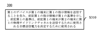
第2の態様は、無線通信方法を提供し、第1のデバイスが第1の端末に第1の指示情報を送信することを含み、前記第1の指示情報が第1の基準を示し、前記第1の基準は、前記第1の端末が第2の端末に第1の物理サイドリンクチャネルを送信するために使用される送信電力を決定するために使用される。 A second aspect provides a wireless communication method, including a first device transmitting first instruction information to a first terminal, the first instruction information indicating a first criterion, and the first instruction information indicating a first criterion; A first criterion is used to determine the transmit power used by the first terminal to transmit a first physical sidelink channel to a second terminal.
第3の態様は、上記の第1の態様または第1の態様の可能な実装形態のいずれかにおける方法を実行するための無線通信デバイスを提供する。具体的に、このデバイスは、上記の第1の態様又は第1の態様の可能な実装形態のいずれかにおける方法を実行するためのユニットを含む。 A third aspect provides a wireless communication device for performing the method in the first aspect above or any of the possible implementations of the first aspect. In particular, the device includes a unit for performing the method in the first aspect or any of the possible implementations of the first aspect described above.
第4の態様は、上記の第2の態様または第2の態様の可能な実装形態のいずれかにおける方法を実行するための無線通信デバイスを提供する。具体的に、このデバイスは、上記の第2の態様又は第2の態様の可能な実装形態のいずれかにおける方法を実行するためのユニットを含む。 A fourth aspect provides a wireless communication device for performing the method in the second aspect above or any of the possible implementations of the second aspect. In particular, the device includes a unit for performing the method in the second aspect above or any of the possible implementations of the second aspect.
第5の態様は、プロセッサとメモリとを含む無線通信デバイスを提供する。メモリは、コンピュータプログラムを記憶し、プロセッサは、メモリに記憶されたコンピュータプログラムを呼び出して実行し、上記第1の態様またはその様々な実施例における方法を実行する。 A fifth aspect provides a wireless communication device that includes a processor and a memory. The memory stores a computer program, and the processor retrieves and executes the computer program stored in the memory to perform the method in the first aspect or various embodiments thereof.
第6の態様は、プロセッサとメモリとを含む無線通信デバイスを提供する。メモリは、コンピュータプログラムを記憶し、プロセッサは、メモリに記憶されたコンピュータプログラムを呼び出して実行し、上記第2の態様またはその様々な実施例における方法を実行する。 A sixth aspect provides a wireless communication device that includes a processor and a memory. The memory stores a computer program, and the processor retrieves and executes the computer program stored in the memory to perform the method of the second aspect or various embodiments thereof.
第7の態様は、上述の第1から第2の態様のいずれか、またはその各実施態様における方法を実施するチップを提供する。 A seventh aspect provides a chip that implements the method in any of the first to second aspects or each embodiment thereof.
具体的には、このチップは、コンピュータプログラムをメモリから呼び出して実行し、チップが実装されたデバイスに、第1の態様から第2の態様のいずれか、またはそれらの実装形態による方法を実行させるプロセッサを含む。 Specifically, this chip calls a computer program from memory and executes it, causing a device mounted with the chip to execute a method according to any of the first to second aspects or their implementation forms. Contains a processor.
第8の態様は、コンピュータに、上述の第1の態様から第2の態様のいずれか、またはそれらの実装形態における方法を実行させるコンピュータプログラムを記憶するコンピュータ可読記憶媒体を提供する。 An eighth aspect provides a computer-readable storage medium storing a computer program that causes a computer to perform a method in any of the first to second aspects described above or an implementation thereof.
第9の態様は、コンピュータに、上述の第1の態様から第2の態様のいずれか、またはそれらの実装形態における方法を実行させるコンピュータプログラム命令を含むコンピュータプログラム製品を提供する。 A ninth aspect provides a computer program product comprising computer program instructions for causing a computer to perform a method in any of the first to second aspects, or implementations thereof, described above.
第10の態様は、コンピュータ上で実行されたときに、コンピュータに、上記の第1から第2の態様のいずれか、またはその様々な実施態様における方法を実行させるコンピュータプログラムを提供する。 A tenth aspect provides a computer program that, when executed on a computer, causes the computer to perform the method in any of the first to second aspects above, or various implementations thereof.
上記の技術的解決策によって、端末デバイスは、データの伝送要求を満足させるのに有利であるように、第1の基準に従って、他の端末に送信される物理サイドリンクチャネルの送信電力を決定することができる。 According to the above technical solution, the terminal device determines the transmission power of the physical sidelink channel transmitted to other terminals according to the first criterion, so as to be advantageous for satisfying the data transmission request. be able to.
以下、本願の実施例における技術案を、本願の実施例における図面を参照して説明するが、明らかに、記述された実施例は本願の一部の実施例であり、全ての実施例ではない。本願における実施例に基づいて、発明的な労働をすることなく当業者によって得られる他のすべての実施例は、本願の保護範囲に属する。 Hereinafter, technical solutions in the embodiments of the present application will be explained with reference to drawings in the embodiments of the present application, but it is clear that the described embodiments are only some of the embodiments of the present application and not all of the embodiments. . All other embodiments obtained by a person skilled in the art based on the embodiments in this application without any inventive labor fall within the protection scope of this application.
なお、本願の実施例の技術方案は、Device to Device ( D2D )通信システム、例えば、Long term Evolution ( LTE )に基づいてD2D通信を行う車両ネットシステム、又はNR-V2Xシステムに適用できる。従来のLTEシステムにおける端末間の通信データがネットワークデバイス(例えば、基地局)を介して受信又は送信される方式とは異なり、車両ネットワークシステムは、端末間の直接通信の方式を採用し、これにより、より高い周波数スペクトル効率及びより低い伝送遅延を有する。 Note that the technical solution of the embodiment of the present application can be applied to a Device to Device (D2D) communication system, for example, a vehicle network system that performs D2D communication based on Long Term Evolution (LTE), or an NR-V2X system. Unlike the method in which communication data between terminals in the conventional LTE system is received or transmitted via a network device (e.g., a base station), the vehicle network system adopts a method of direct communication between terminals, thereby , has higher frequency spectral efficiency and lower transmission delay.
任意選択で、車両ネットワークシステムが基礎とする通信システムは、GSM ( Global System of Mobile communication )システム、CDMA ( Code Division Multiple Access )システム、WCDMA システム、GPRS ( General Packet Radio Service )、LTEシステム、FDD ( Frequency Division Duplex )システム、TDD ( Time Division Duplex )システム、UMTS ( Universal Mobile Telecommunication System )、WiMAX ( Worldwide Interoperability for Microwave Access )通信システム、NR ( New Radio )システム等であってもよい。 Optionally, the communication system on which the vehicle network system is based is a GSM (Global System of Mobile communication) system, a CDMA (Code Division Multiple Access) system, a WCDMA system, a GPRS (General Pa cket Radio Service ), LTE system, FDD ( Frequency Division Duplex) system, TDD (Time Division Duplex) system, UMTS (Universal Mobile Telecommunication System), WiMAX (Worldwide It may also be an interoperability for Microwave Access) communication system, an NR (New Radio) system, or the like.
本願の実施例における端末デバイスは、D2D通信を可能にする端末デバイスであってもよい。例えば、車載端末デバイスであってもよいし、5Gネットワークにおける端末デバイスや将来進化してくるPLMN(Public Land Mobile Network)における端末デバイスなどであってもよく、本願実施例は限定されない。 The terminal device in the embodiment of the present application may be a terminal device that enables D2D communication. For example, it may be an in-vehicle terminal device, a terminal device in a 5G network, a terminal device in a PLMN (Public Land Mobile Network) that will evolve in the future, etc., and the embodiments of the present application are not limited thereto.
図1は、本願の実施例の応用場面の模式図である。図1は、1つのネットワークデバイスと2つの端末デバイスを例示的に示しているが、任意選択で、本願の実施例における無線通信システムは、複数のネットワークデバイスを含んでもよく、各ネットワークデバイスのカバレッジ内に他の数の端末デバイスを含んでもよく、本願の実施例は、これに限定されない。 FIG. 1 is a schematic diagram of an application scene of an embodiment of the present application. Although FIG. 1 exemplarily depicts one network device and two terminal devices, optionally, the wireless communication system in embodiments of the present application may include multiple network devices, with coverage of each network device. Other numbers of terminal devices may be included within the device, and embodiments of the present application are not limited thereto.
任意選択で、当該無線通信システムは、移動管理エンティティ( Mobile Management Entity、MME )、サービングゲートウェイ( Serving Gateway、S-GW )、パケットデータネットワークゲートウェイ( Packet Data Network Gateway、P-GW )などの他のネットワークエンティティをさらに含んでもよく、又は、当該無線通信システムは、セッション管理機能( Session Management Function、SMF )、統一データ管理( Unified Data Management、UDM )、認証サーバ機能( Authentication Server Function、AUSF )などの他のネットワークエンティティをさらに含んでもよく、本願の実施例は、これに限定されない。 Optionally, the wireless communication system includes other devices such as a Mobile Management Entity (MME), a Serving Gateway (S-GW), a Packet Data Network Gateway (P-GW), etc. The wireless communication system may further include a network entity, or the wireless communication system may have a session management function (SMF), a unified data management (UDM), an authentication server function (Authentication Server Function). on, AUSF) etc. Other network entities may also be included, and embodiments of the present application are not limited thereto.
この車両ネットワークシステムでは、端末デバイスはモード3とモード4で通信を行うことができる。 In this vehicle network system, terminal devices can communicate in mode 3 and mode 4.
具体的には、端末デバイス121と端末デバイス122は、D2D通信モードで通信を行うことができ、D2D通信を行う場合、端末デバイス121と端末デバイス122は、D2Dリンク、すなわち、サイドリンク( SideLink、SL )を介して直接通信を行う。ここで、モード3では、端末デバイスの伝送リソースは基地局によって割り当てられ、端末デバイスは、基地局によって割り当てられたリソースに従ってSL上でデータを送信することができる。基地局は、端末デバイスに単一の伝送リソースを割り当てることができ、端末に準静的伝送リソースを割り当てることができる。モード4では、端末デバイスは、センシング(sensing)及び予約(reservation)の伝送方式を採用し、SLリソース上で自律的に送信リソースを選択する。具体的には、端末デバイスは、リソースプール内の利用可能な送信リソースのセットをセンシングで取得し、端末デバイスは、データの送信のために、利用可能な送信リソースのセットからリソースをランダムに選択する。 Specifically, the terminal device 121 and the terminal device 122 can communicate in the D2D communication mode, and when performing D2D communication, the terminal device 121 and the terminal device 122 can communicate using a D2D link, that is, a side link (SideLink, Direct communication is carried out via SL). Here, in mode 3, the transmission resources of the terminal device are allocated by the base station, and the terminal device can transmit data on the SL according to the resources allocated by the base station. The base station can allocate a single transmission resource to a terminal device and can allocate semi-static transmission resources to a terminal. In mode 4, the terminal device adopts a sensing and reservation transmission method and autonomously selects transmission resources on the SL resources. Specifically, the terminal device obtains a set of available transmission resources in a resource pool by sensing, and the terminal device randomly selects a resource from the set of available transmission resources for data transmission. do.
なお、上記モード3及びモード4は、2つの伝送モードを例示したに過ぎず、他の伝送モードが定義されてもよい。例えば、NR-V2Xには、端末デバイスのサイドリンク伝送リソースが基地局によって割り当てられることを示すパターン1と、端末デバイスのサイドリンク伝送リソースが端末によって選択されることを示すパターン2とが導入されている。 Note that the above mode 3 and mode 4 are merely two examples of transmission modes, and other transmission modes may be defined. For example, NR-V2X introduces pattern 1, which indicates that the sidelink transmission resources of the terminal device are allocated by the base station, and pattern 2, which indicates that the sidelink transmission resources of the terminal device are selected by the terminal. ing.
D2D通信は、車両間( Vehicle to Vehicle、V2V )通信、または車両-他のデバイス( Vehicle to Everything、V2X )通信を意味する。V2X通信において、Xは、限定ではないが低速移動無線デバイス、高速移動車載機、又は無線送受信能力を有するネットワーク制御ノード等の、無線受信及び送信能力を有する任意の装置を広く指すことができる。なお、本願の実施例は、主にV2X通信のシナリオに適用されるが、任意の他のD2D通信シナリオにも適用可能であり、本願の実施例は、これに限定されない。 D2D communication refers to vehicle-to-vehicle (V2V) communication or vehicle-to-other device (Vehicle to Everything, V2X) communication. In V2X communications, X can broadly refer to any device with wireless receiving and transmitting capabilities, such as, but not limited to, a slow moving wireless device, a fast moving vehicle-mounted device, or a network control node with wireless transmitting and receiving capabilities. Note that the embodiments of the present application are mainly applied to V2X communication scenarios, but can also be applied to any other D2D communication scenarios, and the embodiments of the present application are not limited thereto.
なお、本明細書において、用語「システム」及び「ネットワーク」は、しばしば、交換可能に使用されることが理解される。ここで言う「及び/又は」とは、単に関連対象を説明する関連関係のことであり、A及び/又はBのように3つの関係があり、A単独の場合、AとBの両方の場合、B単独の場合の3つの場合があることを意味する。また、本文中の「/」は、前後関係オブジェクトが「または」の関係であることを一般的に示す。 Note that in this specification, it is understood that the terms "system" and "network" are often used interchangeably. "And/or" here simply refers to a related relationship that explains the related object, and there are three relationships such as A and/or B, where A alone or both A and B. , B alone. Further, "/" in the text generally indicates that the context object is in the "or" relationship.
図2は、本願の実施例における無線通信方法のフローチャートであり、この方法は、例えば図2に示されるように端末デバイス121又は端末デバイス122のような、車載ネットワークシステムにおける端末デバイスによって実行され、方法200は、以下のステップを含み、
S210において、第1の端末が第1の基準に応じて第1の物理サイドリンクチャネルの目標送信電力を決定し、
S220において、前記第1の端末が前記目標送信電力を利用して第2の端末に前記第1の物理サイドリンクチャネルを送信する。
FIG. 2 is a flowchart of a wireless communication method in an embodiment of the present application, which is executed by a terminal device in the in-vehicle network system, such as the terminal device 121 or the terminal device 122 as shown in FIG.
At S210, the first terminal determines a target transmit power of the first physical sidelink channel according to a first criterion;
At S220, the first terminal transmits the first physical sidelink channel to a second terminal using the target transmission power.
任意選択で、本願の実施例では、前記第1の物理サイドリンクチャネルは、物理サイドリンクブロードキャストチャネル( Physical Sidelink Broadcast Channel、PSBCH )、物理サイドリンクフィードバックチャネル( Physical Sidelink Feedback Channel、PSFCH )、物理サイドリンク共有チャネル( Physical Sidelink Shared Channel、PSSCH )、物理サイドリンク制御チャネル( Physical Sidelink Control Channel、PSCCH )などの端末と端末の間で通信を行うためのサイドリンクチャネルであってもよい。 Optionally, in an embodiment of the present application, the first physical sidelink channel is a physical sidelink broadcast channel (PSBCH), a physical sidelink feedback channel (PSFCH). , physics side It may be a sidelink channel for communicating between terminals, such as a link shared channel (PSSCH) or a physical sidelink control channel (PSCCH).
任意選択で、本願の実施例では、前記第1の基準は、端末間の通信のために使用されるサイドリンクチャネルの送信電力の決定方法を示すために使用され、例えば、前記第1の基準は、送信電力が、経路損失に従って決定されること、又は、送信電力が、伝送されるサイドリンクデータの属性(例えば、優先度、信頼性など)に従って決定されること、又は送信電力が、アップリンク伝送に対するサイドリンクチャネルの干渉に従って決定されること、などを示すことができる。 Optionally, in embodiments of the present application, said first criterion is used to indicate how to determine the transmit power of a sidelink channel used for communication between terminals, e.g. The transmit power is determined according to the path loss, or the transmit power is determined according to the attributes (e.g., priority, reliability, etc.) of the sidelink data being transmitted, or the transmit power is determined according to the Determined according to side link channel interference to link transmission, etc.
任意選択で、ある実施例において、前記第1の基準は、以下の少なくとも1つを指示するために使用され、
端末デバイスの最大送信電力に応じて前記目標送信電力を決定すること、を方式1とし、
第1の構成情報に応じて前記目標送信電力を決定すること、を方式2とし、
第1の送信電力に応じて前記目標送信電力を決定し、前記第1の送信電力が第1の経路損失に応じて決定され、前記第1の経路損失が前記第1の端末とネットワークデバイスとの経路損失であること、を方式3とし、
第2の送信電力に応じて前記目標送信電力を決定し、前記第1の送信電力が第2の経路損失に応じて決定され、前記第2の経路損失が前記第1の端末と前記第2の端末との経路損失であること、を方式4とし、
第1の経路損失に応じて前記目標送信電力を決定し、前記第1の経路損失が前記第1の端末とネットワークデバイスとの経路損失であること、を方式5とし、
第2の経路損失に応じて前記目標送信電力を決定し、前記第2の経路損失が前記第1の端末と前記第2の端末との経路損失であること、を方式6とし、
前記第1の送信電力と前記第2の送信電力のうちの最小値に応じて前記目標送信電力を決定すること、を方式7とし、
前記第1の送信電力と前記第2の送信電力のうちの最大値に応じて前記目標送信電力を決定すること、を方式8とし、
伝送されるサイドリンクデータの第1の属性及び第1の閾値に応じて前記目標送信電力を決定すること、を方式9とし、
前記第1の物理サイドリンクチャネルのタイプに応じて前記目標送信電力を決定すること、を方式10とする。
Optionally, in some embodiments, the first criterion is used to indicate at least one of the following:
Method 1 is to determine the target transmission power according to the maximum transmission power of the terminal device,
Method 2 is to determine the target transmission power according to first configuration information,
The target transmission power is determined according to a first transmission power, the first transmission power is determined according to a first path loss, and the first path loss is determined between the first terminal and the network device. Method 3 is that the path loss is
The target transmission power is determined according to a second transmission power, the first transmission power is determined according to a second path loss, and the second path loss is determined between the first terminal and the second terminal. Method 4 is that the path loss with the terminal is
The target transmission power is determined according to a first path loss, and the first path loss is a path loss between the first terminal and a network device, as method 5;
The target transmission power is determined according to a second path loss, and the second path loss is a path loss between the first terminal and the second terminal, as
Method 7 is to determine the target transmission power according to the minimum value of the first transmission power and the second transmission power,
Method 8 is to determine the target transmission power according to the maximum value of the first transmission power and the second transmission power,
Method 9 is to determine the target transmission power according to a first attribute and a first threshold of side link data to be transmitted;
任意選択で、ある実施例において、該第1の基準は、第1の端末自身が決定することができ、すなわち、第1の端末は、第1の物理サイドリンクチャネルの送信電力を、第1の経路損失、第2の経路損失、または伝送されるサイドリンクデータの属性などの情報に基づいて決定することができ、サイドリンク伝送の信頼性および待ち時間などの送信要求を保証することを容易にする。 Optionally, in some embodiments, the first criterion may be determined by the first terminal itself, i.e., the first terminal determines the transmit power of the first physical sidelink channel based on the first The reliability and latency of the sidelink transmission can be determined based on information such as the path loss of the second path, the second path loss, or the attributes of the sidelink data being transmitted, making it easy to guarantee the transmission requirements such as the reliability and latency of the sidelink transmission. Make it.
任意選択で、ある実施例において、前記第1の基準は、ネットワークデバイスにより設定されても良い。 Optionally, in some embodiments, the first criterion may be set by a network device.
例えば、前記ネットワークデバイスが前記第1の端末に第1の指示情報を送信し、前記第1の指示情報で前記第1の基準を示す。任意選択で、該第1の指示情報は、下り制御情報(Downlink Control Information、DCI )、下り放送情報又は無線リソース制御( Radio Resource Control、RRC )シグナリング、或いは他の下り情報又は下りチャネルに搬送されてもよい。 For example, the network device sends first instruction information to the first terminal, and indicates the first criterion in the first instruction information. Optionally, the first indication information is carried in Downlink Control Information (DCI), downlink broadcast information or Radio Resource Control (RRC) signaling, or other downlink information or downlink channels. It's okay.
例えば、ネットワークデバイスは、第1の基準によって、第1の端末が第1の経路損失、第2の経路損失又はサイドリンクデータの属性などの情報に基づいてサイドリンクチャネルの送信電力を決定するように構成することによって、アップリンクチャネルに対するサイドリンクチャネルの干渉を制御することができる。 For example, the network device may cause the first terminal to determine the transmit power of the sidelink channel based on information such as a first path loss, a second path loss, or an attribute of the sidelink data, according to the first criterion. By configuring this, interference of sidelink channels with respect to uplink channels can be controlled.
任意選択で、他の実施例において、前記第1の基準が第3の端末により構成され、前記第3の端末が前記第1の端末が位置する通信グループのグループヘッダ端末である。 Optionally, in another embodiment, said first reference is constituted by a third terminal, said third terminal being a group header terminal of a communication group in which said first terminal is located.
なお、本願の実施例において、グループヘッダ端末は、グループの管理、メンテナンス、新しいグループメンバの加入、グループメンバの退出、リソース管理、リソース割り当て、リソース調整などの機能のうち少なくとも1つを有する端末であってもよい。 In the embodiments of the present application, the group header terminal is a terminal that has at least one of the following functions: group management, maintenance, joining of new group members, leaving of group members, resource management, resource allocation, resource adjustment, etc. There may be.
任意選択で、前記第3の端末は、第1の基準を示す構成情報を第1の端末に送信することができる。任意選択で、前記構成情報は、サイドリンク制御情報( Sidelink Control Information、SCI )又はサイドリンク無線リソース制御( Sidelink RRC、S-RRC )シグナリング又は他のサイドリンク情報若しくはサイドリンクチャネルに搬送される。 Optionally, the third terminal may send configuration information indicating the first criteria to the first terminal. Optionally, the configuration information is carried in Sidelink Control Information (SCI) or Sidelink Radio Resource Control (Sidelink RRC, S-RRC) signaling or other sidelink information or sidelink channels.
本願の実施例では、グループヘッダ端末は、第1の基準によってグループ内端末の送信電力を制御することにより、グループ内端末間の通信の信頼性及び遅延要求を保証し、車両編成などの信頼性及び遅延要求が高いシナリオに適用することができる。 In the embodiment of the present application, the group header terminal controls the transmission power of the terminals in the group according to the first criterion, thereby guaranteeing the reliability of communication and delay requirements among the terminals in the group, and ensuring the reliability of vehicle formation, etc. and can be applied to scenarios with high delay requirements.
任意選択で、他の実施例として、前記第1の基準は、予め設定された基準であり、例えば、該第1の基準は、プロトコル定義された基準であり、プロトコル定義された該第1の基準を前記第1端末のために構成できる。そして、第1の端末が予め設定できる第1の基準に応じて、第1の物理サイドリンクチャネルの送信電力を決定することができる。 Optionally, in another embodiment, the first criterion is a preset criterion, for example, the first criterion is a protocol-defined criterion, and the first criterion is a protocol-defined criterion. Criteria can be configured for the first terminal. Then, the transmission power of the first physical sidelink channel can be determined according to a first criterion that can be set in advance by the first terminal.
以下、上記の方式1~方式10の実施方式を説明する。 Hereinafter, implementation methods of the above methods 1 to 10 will be explained.
方式1:
方式1に応じて前記目標送信電力を決定することを前記第1の基準で指示する場合、該第1の端末が該第1の端末の最大送信電力を該第1の物理サイドリンクチャネルの目標送信電力として決定することができ、なお、ここの第1の端末の最大送信電力は、予め設定され、例えば、23dBmである。
Method 1:
When the first criterion instructs to determine the target transmission power according to method 1, the first terminal sets the maximum transmission power of the first terminal to the target transmission power of the first physical sidelink channel. Note that the maximum transmission power of the first terminal here is set in advance, and is, for example, 23 dBm.
方式2:
方式2に応じて前記目標送信電力を決定することを前記第1の基準で指示する場合、該第1の端末が第1の構成情報に応じて該第1の物理サイドリンクチャネルの目標送信電力を決定することができる。
Method 2:
When the first criterion instructs to determine the target transmission power according to method 2, the first terminal determines the target transmission power of the first physical sidelink channel according to the first configuration information. can be determined.
任意選択で、前記第1の構成情報が第1のマッピング関係を含み、例えば、前記第1のマッピング関係は、優先度情報及びチャネル輻輳比(Channel Busy Ratio、CBR)のうちの少なくとも1つと最大送信電力とのマッピング関係であっても良く、そして、第1の端末は、伝送されるサイドリンクデータの優先度情報及び/又は現在のチャネルのCBRに応じて、第1のマッピング関係を参照し、最大送信電力を決定することができ、ここの最大送信電力は、第1の構成情報に応じて決定された最大送信電力であっても良い。さらに、前記第1の端末は、該第1の構成情報で決定された最大送信電力に応じて、前記第1の物理サイドリンクチャネルを送信する目標送信電力を決定する。例えば、該最大送信電力を前記第1の物理サイドリンクチャネルの送信の目標送信電力として決定してもよい。 Optionally, the first configuration information includes a first mapping relationship, for example, the first mapping relationship includes at least one of priority information and a channel busy ratio (CBR) and a maximum The first terminal may refer to the first mapping relationship according to the priority information of the transmitted sidelink data and/or the CBR of the current channel. , a maximum transmission power may be determined, where the maximum transmission power may be a maximum transmission power determined according to the first configuration information. Furthermore, the first terminal determines a target transmission power for transmitting the first physical sidelink channel according to the maximum transmission power determined by the first configuration information. For example, the maximum transmission power may be determined as the target transmission power for transmission of the first physical sidelink channel.
例えば、前記第1のマッピング関係は、表1で示す。 For example, the first mapping relationship is shown in Table 1.

伝送されるサイドリンクデータの優先度が1、現在のチャネルのCBRが0.8である場合、表1によって、最大送信電力を18dBmとして決定し、さらに、第1の物理サイドリンクチャネルの目標送信電力を18dBmとして決定することができる。 When the priority of the sidelink data to be transmitted is 1 and the CBR of the current channel is 0.8, the maximum transmission power is determined as 18 dBm according to Table 1, and the target transmission of the first physical sidelink channel is The power can be determined as 18 dBm.
なお、CBRが小さいほど、現在伝送されているチャネルが少なく、優先度が高いほど、データの優先伝送を保障し、したがって、本願の実施例では、伝送されるサイドリンクデータの優先度が高いほど、CBRが小さいほど、対応する最大送信電力が大きくなるように構成することができ、これにより、優先度の高いサイドリンクデータの信頼性の高い伝送を保証し、同時に、他のチャネルの伝送に対する干渉をあまり与えないようにすることができる。 It should be noted that the smaller the CBR, the fewer channels are currently being transmitted, and the higher the priority, the higher the priority transmission of data. Therefore, in the embodiment of the present application, the higher the priority of side link data to be transmitted, the more , the smaller the CBR, the larger the corresponding maximum transmit power can be configured, which ensures reliable transmission of high-priority sidelink data and at the same time It is possible to prevent too much interference.
なお、本願の実施例において、前記第1のマッピング関係は、伝送されるデータの他の属性と最大送信電力とのマッピング関係であっても良く、例えば、前記第1のマッピング関係は、サービス品質(Quality of Service、QoS)、信頼性又は遅延などの属性、CBRと最大送信電力とのマッピング関係であっても良く、本願の実施例がこれに限定されない。 In the embodiment of the present application, the first mapping relationship may be a mapping relationship between another attribute of transmitted data and the maximum transmission power; for example, the first mapping relationship may be a mapping relationship between the quality of service and the maximum transmission power. (Quality of Service, QoS), attributes such as reliability or delay, or a mapping relationship between CBR and maximum transmission power, and the embodiments of the present application are not limited thereto.
方式3:
方式3で決定された送信電力で物理サイドリンクチャネルを送信することを該第1の基準で指示する場合、該第1の端末は、第1の端末とネットワークデバイスとの第1の経路損失に応じて、第1の送信電力を決定することができる。さらに、該第1の端末は、該第1の送信電力に応じて、前記第1の物理サイドリンクチャネルの目標送信電力を決定する。
Method 3:
When the first criterion indicates that the physical sidelink channel is to be transmitted with the transmission power determined in Scheme 3, the first terminal has a first path loss between the first terminal and the network device. Accordingly, the first transmit power can be determined. Further, the first terminal determines a target transmission power of the first physical sidelink channel according to the first transmission power.

また、例えば、該第1の端末は、該第1の送信電力、該第1の端末デバイスの最大送信電力及び第2の構成情報に応じて決定された最大送信電力のうちの最小値を前記第1の物理サイドリンクチャネルの目標送信電力として決定しても良い。ここで、前記第2の構成情報は、例えば、方式2の第1の構成情報、又は他の構成情報であっても良く、該第2の構成情報は、ネットワークデバイスにより設定され、又は、予め設定され、又は、グループヘッダ端末により設定されても良い。 Further, for example, the first terminal transmits the minimum value of the first transmission power, the maximum transmission power of the first terminal device, and the maximum transmission power determined according to the second configuration information. It may be determined as the target transmission power of the first physical sidelink channel. Here, the second configuration information may be, for example, the first configuration information of method 2 or other configuration information, and the second configuration information is set by a network device or in advance. or may be set by the group header terminal.
任意選択で、ある実施例において、該第1の端末は、該第1の送信電力を前記第1の物理サイドリンクチャネルの目標送信電力として決定しても良い。 Optionally, in some embodiments, the first terminal may determine the first transmit power as a target transmit power of the first physical sidelink channel.
例えば、第1の送信電力を決定する時に、第1の経路損失を考え、前記第1の端末の最大送信電力の限定を考え、例えば、第1の経路損失に応じて決定された送信電力及び該第1の端末の最大送信電力のうちの最小値を前記第1の送信電力として決定する場合、該第1の端末は、該第1の送信電力を前記第1の物理サイドリンクチャネルの目標送信電力として直接決定することができる。 For example, when determining the first transmission power, the first path loss is considered and the maximum transmission power of the first terminal is considered, and the transmission power and the transmission power determined according to the first path loss and When determining the minimum value of the maximum transmission powers of the first terminal as the first transmission power, the first terminal sets the first transmission power to the target of the first physical sidelink channel. It can be determined directly as the transmit power.
任意選択で、該第1の経路損失は、ネットワークデバイスからの参照信号を測定して決定し、例えば、第1の端末は、ネットワークデバイスにより送信されたダウンリンクチャネル又はダウンリンク信号を測定して、該ダウンリンクチャネル又はダウンリンク信号の送信電力に応じて、該第1の経路損失を決定する。 Optionally, the first path loss is determined by measuring a reference signal from a network device, e.g., the first terminal measures a downlink channel or a downlink signal transmitted by a network device. , the first path loss is determined depending on the transmission power of the downlink channel or downlink signal.
方式4:
方式4で決定された送信電力で物理サイドリンクチャネルを送信することを該第1の基準で指示する場合、該第1の端末は、第1の端末と第2の端末との第2の経路損失に応じて、第2の送信電力を決定することができる。さらに、該第1の端末は、該第2の送信電力に応じて前記第1の物理サイドリンクチャネルの目標送信電力を決定することができる。
Method 4:
When the first standard instructs to transmit the physical sidelink channel with the transmission power determined in method 4, the first terminal transmits the physical sidelink channel using the transmission power determined in method 4. The second transmit power can be determined depending on the loss. Further, the first terminal can determine a target transmit power of the first physical sidelink channel according to the second transmit power.

また、例えば、該第1の端末は、該第2の送信電力、該第1の端末デバイスの最大送信電力及び第3の構成情報に応じて決定された最大送信電力のうちの最小値を前記第1の物理サイドリンクチャネルの目標送信電力として決定しても良い。ここで、前記第3の構成情報は、例えば、方式2の第1の構成情報、又は、他の構成情報であっても良い。任意選択で、該第3の構成情報は、ネットワークデバイスにより設定されても良いし、予め設定されても良いし、グループヘッダ端末により設定されても良い。 Further, for example, the first terminal transmits the minimum value of the second transmission power, the maximum transmission power of the first terminal device, and the maximum transmission power determined according to the third configuration information. It may be determined as the target transmission power of the first physical sidelink channel. Here, the third configuration information may be, for example, the first configuration information of method 2 or other configuration information. Optionally, the third configuration information may be configured by the network device, preconfigured, or configured by the group header terminal.
任意選択で、該第1の端末は、該第2の送信電力を前記第1の物理サイドリンクチャネルの目標送信電力として決定する。 Optionally, the first terminal determines the second transmit power as a target transmit power of the first physical sidelink channel.
例えば、第2の送信電力を決定する時に、第2の経路損失を考え、また、前記第1の端末の最大送信電力の制限を考え、例えば、第2の経路損失に応じて決定された送信電力及び該第1の端末の最大送信電力のうちの最小値を前記第2の送信電力として決定する場合、該第1の端末は、該第2の送信電力を前記第1の物理サイドリンクチャネルの目標送信電力として直接決定することができる。 For example, when determining the second transmission power, consider the second path loss and also consider the limit on the maximum transmission power of the first terminal, and for example, the transmission determined according to the second path loss. When determining the minimum value of the power and the maximum transmission power of the first terminal as the second transmission power, the first terminal sets the second transmission power to the first physical sidelink channel. can be determined directly as the target transmit power.
任意選択で、第2の経路損失は、サイドリンクチャネルを測定及び/又はフィードバックして取得し、例えば、第1の端末がサイドリンク参照信号を送信し、第2の端末が該サイドリンク参照信号に応じてサイドリンク参照信号受信電力(Sidelink Reference Signal Receiving Power、S-RSRP)を測定し、さらに、該S-RSRPを第1の端末にフィードバックすることで、第1の端末が該第2の経路損失を決定し、又は、該第1の端末が第2の端末からのサイドリンクチャネル又はサイドリンク信号を測定し、さらに、該サイドリンクチャネル又はサイドリンク信号の送信電力に応じて、第2の経路損失を決定する。 Optionally, the second path loss is obtained by measuring and/or feeding back a sidelink channel, e.g., the first terminal transmits a sidelink reference signal and the second terminal transmits a sidelink reference signal. The first terminal measures the sidelink reference signal receiving power (S-RSRP) according to the second terminal, and further feeds back the S-RSRP to the first terminal. determining a path loss, or the first terminal measuring a sidelink channel or signal from a second terminal; Determine the path loss of
方式5:
方式5に応じて目標送信電力を決定することを該第1の基準で指示する場合、該第1の端末は、第1の端末とネットワークデバイスとの第1の経路損失に応じて、第1の送信電力を決定することができる。
Method 5:
When the first criterion instructs to determine the target transmission power according to method 5, the first terminal determines the target transmission power according to the first path loss between the first terminal and the network device. It is possible to determine the transmit power of
任意選択で、該第1の端末は、該第1の送信電力に応じて、前記第1の物理サイドリンクチャネルの目標送信電力を決定することができる。 Optionally, the first terminal may determine a target transmit power for the first physical sidelink channel in response to the first transmit power.
例えば、該第1の送信電力と該第1の端末デバイスの最大送信電力のうちの最小値を前記第1の物理サイドリンクチャネルの目標送信電力として決定する。 For example, the minimum value of the first transmission power and the maximum transmission power of the first terminal device is determined as the target transmission power of the first physical sidelink channel.
また、例えば、該第1の端末は、該第1の送信電力を前記第1の物理サイドリンクチャネルの目標送信電力として決定しても良い。 Also, for example, the first terminal may determine the first transmission power as the target transmission power of the first physical sidelink channel.
また、例えば、該第1の端末は、第1の送信電力、該第1の端末デバイスの最大送信電力、及び第4の構成情報に応じて決定された最大送信電力のうちの最小値を前記第1の物理サイドリンクチャネルの目標送信電力として決定することができ、ここで、前記第4の構成情報は、例えば、方式2の第1の構成情報であり、又は、他の構成情報であり、該第4の構成情報がネットワークデバイスにより設定され、又は、予め設定され、又は、グループヘッダ端末により設定されても良い。 Further, for example, the first terminal transmits the minimum value of the first transmission power, the maximum transmission power of the first terminal device, and the maximum transmission power determined according to the fourth configuration information. The target transmission power of the first physical sidelink channel may be determined as the target transmission power of the first physical sidelink channel, where the fourth configuration information is, for example, the first configuration information of scheme 2 or other configuration information. , the fourth configuration information may be set by a network device, or may be preset, or may be set by a group header terminal.
任意選択で、該第1の経路損失の決定方式は、上記の記載を参照し、ここで説明を省略する。 Optionally, the first path loss determination scheme is referred to above and will not be described here.
方式6:
方式6に応じて目標送信電力を決定することを該第1の基準で指示する場合、該第1の端末は、第1の端末と第2の端末との第2の経路損失に応じて、第2の送信電力を決定することができる。
Method 6:
When the first criterion instructs to determine the target transmission power according to
任意選択で、該第1の端末は、該第2の送信電力に応じて、前記第1の物理サイドリンクチャネルの目標送信電力を決定することができる。 Optionally, the first terminal may determine a target transmit power for the first physical sidelink channel in response to the second transmit power.
例えば、該第2の送信電力と該第1の端末デバイスの最大送信電力のうちの最小値を前記第1の物理サイドリンクチャネルの目標送信電力として決定する。 For example, the minimum value of the second transmission power and the maximum transmission power of the first terminal device is determined as the target transmission power of the first physical sidelink channel.
また、例えば、該第1の端末は、該第2の送信電力を前記第1の物理サイドリンクチャネルの目標送信電力として決定しても良い。 Further, for example, the first terminal may determine the second transmission power as the target transmission power of the first physical sidelink channel.
また、例えば、該第1の端末は、第2の送信電力、該第1の端末デバイスの最大送信電力、及び第5の構成情報に応じて決定された最大送信電力のうちの最小値を前記第1の物理サイドリンクチャネルの目標送信電力として決定しても良く、ここで、前記第5の構成情報は、例えば、方式2の第1の構成情報であり、又は、他のネットワークの構成情報であり、該第5の構成情報がネットワークデバイスにより設定され、又は、予め設定され、又は、グループヘッダ端末により設定されても良い。 Further, for example, the first terminal transmits the minimum value of the second transmission power, the maximum transmission power of the first terminal device, and the maximum transmission power determined according to the fifth configuration information. It may be determined as the target transmission power of the first physical sidelink channel, where the fifth configuration information is, for example, the first configuration information of scheme 2, or the configuration information of another network. and the fifth configuration information may be set by a network device, or may be preset, or may be set by a group header terminal.
任意選択で、該第2の経路損失の決定方式は、上記の記載を参照し、ここで説明を省略する。 Optionally, the second path loss determination scheme is referred to above and will not be described here.
任意選択で、本願の実施例において、ネットワークデバイスは、特定の条件を満たす場合、該第1の端末が方式3又は方式4、又は方式5又は方式6を利用して決定された送信電力で物理サイドリンクチャネルを送信するように該第1の基準で指示する。 Optionally, in embodiments of the present application, the network device is configured such that if certain conditions are met, the first terminal performs a physical The first criterion indicates to transmit a side link channel.
例えば、該ネットワークデバイスは、伝送されるデータの第1の属性に従って、前記第1の基準を決定し、限定ではなく例として、前記第1の属性は、
優先度、信頼性、遅延、伝送レート、スループット、伝送距離又は通信距離、QoS、5Gサービス品質指示(5G QoS Indicator、5QI)、V2Xサービス品質指示(V2X QoS Indicator、VQI)のうちの少なくとも1つを含む。
For example, the network device determines the first criterion according to a first attribute of data to be transmitted, and by way of example and not limitation, the first attribute is:
At least one of priority, reliability, delay, transmission rate, throughput, transmission distance or communication distance, QoS, 5G quality of service indicator (5G QoS Indicator, 5QI), V2X quality of service indicator (V2X QoS Indicator, VQI) including.
第1の属性が優先度であることを例とし、該ネットワークデバイスは、伝送されるデータの優先度が高い(例えば、優先度の値が第1の閾値よりも小さい)場合、第1の端末が方式4又は方式6で決定された送信電力を利用して物理サイドリンクチャネルを送信するように指示し、又は、伝送されるデータの優先度が低い(例えば、優先度の値が第1の閾値以上である)場合、第1の端末が方式3又は方式5で決定された送信電力を利用して物理サイドリンクチャネルを送信するように指示する。
For example, if the first attribute is a priority, the network device transmits data to the first terminal if the transmitted data has a high priority (e.g., the priority value is smaller than the first threshold). instructs the physical sidelink channel to be transmitted using the transmit power determined by method 4 or
通常、上記の電力制御方式を利用して、サイドリンクデータの優先度が高い場合、第1の端末が第2の経路損失において目標送信電力を決定するように指示し、サイドリンクデータの正常伝送を優先的に保証し、サイドリンクデータの優先度が低い場合、第1の端末が第1の経路損失に応じて目標送信電力を決定し、さらに、該目標送信電力でサイドリンクチャネルを送信するように指示し、アップリンク伝送に対するサイドリンク伝送の干渉を低減させることができる。 Normally, using the above power control method, if the sidelink data has a high priority, the first terminal instructs the first terminal to determine the target transmission power at the second path loss, and the sidelink data is successfully transmitted. If the sidelink data has a low priority, the first terminal determines the target transmission power according to the first path loss, and further transmits the sidelink channel with the target transmission power. The interference of sidelink transmissions with respect to uplink transmissions can be reduced.
同様、第1の端末は、特定の条件を満たす場合、異なる決定方式を自ら選択し、物理サイドリンクチャネルを送信する目標送信電力を決定し、例えば、第1の端末は、伝送されるサイドリンクデータの優先度が高い場合、方式4又は方式6で決定された送信電力を選択して物理サイドリンクチャネルを送信し、又は、伝送されるサイドリンクデータの優先度が低い場合、方式3又は方式5で決定された送信電力を選択して物理サイドリンクチャネルを送信しても良い。
Similarly, if the first terminal satisfies certain conditions, the first terminal selects a different determination scheme by itself and determines the target transmission power for transmitting the physical sidelink channel, for example, the first terminal If the priority of the data is high, the transmission power determined by method 4 or
又は、第1の端末が異なる条件において、異なる決定方式を選択し、物理サイドリンクチャネルを送信する目標送信電力を決定するように構成し、例えば、第1の端末が伝送されるサイドリンクデータの優先度が高い場合、方式4又は方式6で決定された送信電力を選択して物理サイドリンクチャネルを送信するように構成し、又は、前記第1の端末が伝送されるサイドリンクデータの優先度が低い場合、方式3又は方式5で決定された送信電力を選択して物理サイドリンクチャネルを送信するように構成しても良い。
Alternatively, the first terminal is configured to select different determination methods under different conditions and determine the target transmission power for transmitting the physical sidelink channel, for example, the first terminal If the priority is high, the transmission power determined by method 4 or
方式7:
方式7に応じて目標送信電力を決定することを該第1の基準で指示する場合、該第1の端末は、第1の送信電力と第2の送信電力のうちの最小値に応じて前記目標送信電力を決定することができる。
Method 7:
When the first standard instructs to determine the target transmission power according to method 7, the first terminal determines the target transmission power according to the minimum value of the first transmission power and the second transmission power. A target transmit power can be determined.

例えば、該第1の端末が第1の経路損失に応じてP1を計算する時に該第1の端末の最大送信電力の制限を考え、第2の経路損失に応じてP2を計算する時に該第1の端末の最大送信電力の制限を考え、この時、該第1の端末は、P1及びP2のうちの最小値を目標送信電力として選定してもよい。 For example, when the first terminal calculates P 1 according to the first path loss, consider the maximum transmission power limit of the first terminal, and when calculating P 2 according to the second path loss. Considering the limitation of the maximum transmission power of the first terminal, at this time, the first terminal may select the minimum value of P 1 and P 2 as the target transmission power.

例えば、該第1の端末が第1の経路損失に応じてP1を決定し、第2の経路損失に応じてP2を決定し、この時、該第1の端末は、P1 、P2及び該第1の端末の最大送信電力のうちの最小値を目標送信電力として選定してもよい。 For example, the first terminal determines P 1 according to a first path loss and determines P 2 according to a second path loss, and at this time, the first terminal determines P 1 , P 2 and the maximum transmission power of the first terminal may be selected as the target transmission power.

任意選択で、該第6の構成情報が他の構成情報であってもよく、本願の実施例がこれに限定されない。 Optionally, the sixth configuration information may be other configuration information, and embodiments of the present application are not limited thereto.
任意選択で、該第6の構成情報は、ネットワークにより設定され、又は、予め設定され、又はグループヘッダ端末により設定される。 Optionally, the sixth configuration information is set by the network or preset or set by the group header terminal.
なお、該方式7において、第1の送信電力と第2の送信電力の決定方式は、上記の実施例の記載を参照し、ここで説明を省略する。 Note that in the method 7, the method for determining the first transmission power and the second transmission power will be described with reference to the above embodiment, and the description thereof will be omitted here.
任意選択で、特定の条件を満たす場合、方式7で物理サイドリンクチャネルの送信電力を決定することを該第1の基準で指示し、例えば、伝送されるサイドリンクデータの優先度が低い、又は信頼性要求が低い場合、第1の送信電力及び第2の送信電力のうちの最小値を利用して物理サイドリンクチャネルの送信電力を決定することを該第1の基準で指示することで、アップリンクチャネルに対するサイドリンクチャネルの干渉を低減させることができる。 Optionally, the first criterion indicates that scheme 7 determines the transmit power of the physical sidelink channel if certain conditions are met, e.g. the sidelink data to be transmitted has a low priority; When the reliability requirement is low, the first criterion instructs to determine the transmission power of the physical sidelink channel using the minimum value of the first transmission power and the second transmission power, Interference of sidelink channels to uplink channels can be reduced.
方式8:
方式8に応じて目標送信電力を決定することを該第1の基準で指示する場合、該第1の端末は、第1の送信電力及び第2の送信電力のうちの最大値に応じて前記目標送信電力を決定してもよい。
Method 8:
When the first criterion instructs to determine the target transmission power according to method 8, the first terminal determines the target transmission power according to the maximum value of the first transmission power and the second transmission power. A target transmission power may be determined.

例えば、該第1の端末が第1の経路損失に応じてP1を計算する時に該第1の端末の最大送信電力の制限を考え、第2の経路損失に応じてP2を計算する時に該第1の端末の最大送信電力の制限を考え、この時、該第1の端末は、P1 及びP2のうちの最大値を目標送信電力として選定してもよい。 For example, when the first terminal calculates P 1 according to the first path loss, consider the maximum transmission power limit of the first terminal, and when calculating P 2 according to the second path loss. Considering the limitation of the maximum transmission power of the first terminal, at this time, the first terminal may select the maximum value of P 1 and P 2 as the target transmission power.

例えば、該第1の端末が第1の経路損失に応じてP1を決定し、第2の経路損失に応じてP2を決定し、この時、該第1の端末は、P1及びP2の最大値と該第1の端末の最大送信電力とを比較し、該最大値及び第1の端末の最大送信電力のうちの最小値を目標送信電力決定する。 For example, the first terminal determines P 1 according to a first path loss and determines P 2 according to a second path loss, and at this time, the first terminal determines P 1 and P 2 and the maximum transmission power of the first terminal, and the minimum value of the maximum value and the maximum transmission power of the first terminal is determined as the target transmission power.

任意選択で、該第7の構成情報が他の構成情報であってもよく、本願の実施例がこれに限定されない。 Optionally, the seventh configuration information may be other configuration information, and embodiments of the present application are not limited thereto.
任意選択で、該第7の構成情報は、ネットワークにより設定され、又は、予め設定され、又はグループヘッダ端末により設定される。 Optionally, the seventh configuration information is set by the network or preset or set by the group header terminal.
なお、該方式8において、第1の送信電力と第2の送信電力の決定方式は、上記の実施例の記載を参照し、ここで説明を省略する。 Note that in the method 8, the method for determining the first transmission power and the second transmission power will be described with reference to the above embodiment, and the description thereof will be omitted here.
任意選択で、特定の条件を満たす場合、方式8で物理サイドリンクチャネルの送信電力を決定することを該第1の基準で指示し、例えば、伝送されるサイドリンクデータの優先度が高い、又は信頼性要求が高い場合、第1の送信電力及び第2の送信電力のうちの最大値を利用して送信電力を決定することを該第1の基準で指示することで、サイドリンクチャネルの伝送の信頼性及び遅延要求を保証することができる。 Optionally, the first criterion indicates that scheme 8 determines the transmit power of the physical sidelink channel if certain conditions are met, e.g. the sidelink data to be transmitted has a high priority; When reliability requirements are high, the transmission of the side link channel is improved by instructing based on the first criterion that the maximum value of the first transmission power and the second transmission power is used to determine the transmission power. reliability and delay requirements can be guaranteed.
方式9:
方式9に応じて目標送信電力を決定することを該第1の基準で指示する場合、該第1の端末は、第1の閾値及び伝送されるサイドリンクデータの第1の属性に応じて、前記目標送信電力を決定してもよい。
Method 9:
When the first criterion instructs to determine the target transmission power according to Scheme 9, the first terminal determines the target transmission power according to the first threshold and the first attribute of the sidelink data to be transmitted. The target transmission power may be determined.
任意選択で、該第1の閾値は、予め設定され、又はネットワークにより設定され、又は、グループヘッダ端末により設定されても良い。 Optionally, the first threshold may be preset or set by the network or set by the group header terminal.
限定ではなく例として、前記第1の属性は、
優先度、信頼性、遅延、伝送レート、スループット、伝送距離又は通信距離、QoS、5Gサービス品質指示(5G QoS Indicator、5QI)、V2Xサービス品質指示(V2X QoS Indicator、VQI)のうちの少なくとも1つを含む。
By way of example and not limitation, said first attribute is
At least one of priority, reliability, delay, transmission rate, throughput, transmission distance or communication distance, QoS, 5G Quality of Service Indicator (5G QoS Indicator, 5QI), V2X Quality of Service Indicator (V2X QoS Indicator, VQI) including.
従って、第1の閾値は、
優先度閾値、信頼性閾値、遅延閾値、伝送レート閾値、スループット閾値、伝送距離閾値、5QI閾値、VQI閾値のうちの少なくとも1つである。
Therefore, the first threshold is
It is at least one of a priority threshold, a reliability threshold, a delay threshold, a transmission rate threshold, a throughput threshold, a transmission distance threshold, a 5QI threshold, and a VQI threshold.
例えば、前記第1の属性が優先度情報である場合、前記第1の閾値が優先度閾値であり、伝送されるサイドリンクデータの優先度の値が該第1の閾値以下、即ち、伝送されるサイドリンクデータの優先度が高い場合、該第1の端末は、第2の経路損失に応じて目標送信電力を決定し、さらに、該目標送信電力で前記第1の物理サイドリンクチャネルを送信し、又は、伝送されるサイドリンクデータの優先度の値が該第1の閾値よりも大きく、伝送されるサイドリンクデータの優先度が低い場合、該第1の端末は、第1の経路損失に応じて目標送信電力を決定し、さらに、該目標送信電力で前記第1の物理サイドリンクチャネルを送信してもよい。このように、優先度の高いサイドリンクデータの伝送を保証するとともに、アップリンク伝送に対する優先度の低いサイドリンク伝送の干渉を低減させることができる。 For example, when the first attribute is priority information, the first threshold is a priority threshold, and the priority value of the side link data to be transmitted is less than or equal to the first threshold, that is, if the priority value of the side link data to be transmitted is less than or equal to the first threshold, If the priority of the sidelink data is high, the first terminal determines a target transmission power according to the second path loss, and further transmits the first physical sidelink channel with the target transmission power. or, if the priority value of the sidelink data to be transmitted is greater than the first threshold and the priority of the sidelink data to be transmitted is low, the first terminal A target transmission power may be determined according to the target transmission power, and the first physical sidelink channel may be transmitted using the target transmission power. In this way, it is possible to guarantee the transmission of high-priority sidelink data and reduce interference of low-priority sidelink transmission with uplink transmission.
また、例えば、前記第1の属性が信頼性である場合、前記第1の閾値が信頼性閾値である。伝送されるサイドリンクデータの信頼性要求が該第1の閾値(例えば、90%又は95%)以下である場合、該第1の端末は、第1の経路損失に応じて目標送信電力を決定し、さらに、該目標送信電力で前記第1の物理サイドリンクチャネルを送信し、又は、伝送されるサイドリンクデータの信頼性要求が該第1の閾値よりも高い場合、該第1の端末は、第2の経路損失に応じて目標送信電力を決定し、さらに、該目標送信電力で前記第1の物理サイドリンクチャネルを送信することができる。このように、信頼性要求の高いサイドリンクデータの伝送を保証するとともに、アップリンク伝送に対する信頼性要求の低いサイドリンク伝送の干渉を低減させることができる
任意選択で、他の実施例において、該第1の端末は、第1の閾値及び伝送されるサイドリンクデータの第1の属性に応じて、前記目標送信電力を決定してもよいし、第1の閾値、伝送されるサイドリンクデータの第1の属性、前記第1の端末の最大送信電力に応じて前記目標送信電力を決定してもよい。
Further, for example, when the first attribute is reliability, the first threshold is a reliability threshold. If the reliability requirement of the sidelink data to be transmitted is less than or equal to the first threshold (e.g., 90% or 95%), the first terminal determines a target transmission power according to the first path loss. and further transmitting the first physical sidelink channel at the target transmit power, or if the reliability requirement of the transmitted sidelink data is higher than the first threshold, the first terminal , a target transmission power can be determined according to the second path loss, and the first physical sidelink channel can be further transmitted with the target transmission power. In this way, it is possible to ensure the transmission of sidelink data with high reliability requirements while reducing the interference of sidelink transmissions with low reliability requirements to uplink transmissions. Optionally, in other embodiments, the The first terminal may determine the target transmission power according to the first threshold and the first attribute of the sidelink data to be transmitted, or the first terminal may determine the target transmission power according to the first threshold and the first attribute of the sidelink data to be transmitted. The target transmission power may be determined according to a first attribute and a maximum transmission power of the first terminal.
方式10:
方式10に応じて目標送信電力を決定することを該第1の基準で指示する場合、該第1の端末は、第1の物理サイドリンクチャネルのタイプに応じて前記目標送信電力を決定してもよい。
Method 10:
When the first criterion instructs to determine the target transmission power according to
例えば、該第1の物理サイドリンクチャネルがPSBCH、PSCCH又はPSFCHである場合、該第1の端末は、第2の経路損失に応じて目標送信電力を決定し、さらに、該目標送信電力で該第1の物理サイドリンクチャネルを送信すると決定し、通常、PSBCH、PSCCH及びPSFCH的信頼性又は重要性が高いため、第2の経路損失に応じて決定された送信電力でこのサイドリンクチャネルを送信することで、このサイドリンクチャネルの伝送の信頼性及び遅延等の要求を保証するのに有利である。 For example, when the first physical sidelink channel is PSBCH, PSCCH, or PSFCH, the first terminal determines a target transmit power according to the second path loss, and further determines the target transmit power according to the second path loss. Deciding to transmit a first physical sidelink channel and transmitting this sidelink channel with a transmit power determined according to a second path loss, since the reliability or importance of PSBCH, PSCCH and PSFCH is usually high. This is advantageous in guaranteeing requirements such as transmission reliability and delay of this side link channel.
また、例えば、該第1の物理サイドリンクチャネルがPSSCHである場合、該第1の端末は、第1の経路損失に応じて目標送信電力を決定し、さらに、該目標送信電力で該第1の物理サイドリンクチャネルを送信すると決定し、通常、PSSCHの信頼性又は重要度が低いため、第1の経路損失に応じて決定された送信電力でこのサイドリンクチャネルを送信することで、アップリンク伝送に対するサイドリンク伝送の干渉を回避するのに有利である。 Further, for example, when the first physical sidelink channel is a PSSCH, the first terminal determines the target transmission power according to the first path loss, and further determines the target transmission power using the target transmission power. Since the reliability or importance of the PSSCH is usually low, transmitting this sidelink channel with a transmit power determined according to the first path loss increases the uplink It is advantageous to avoid sidelink transmission interference with the transmission.
なお、該第1の端末の目標送信電力は、該第1の端末の最大送信電力を超えない。即ち、上記の実施例で計算された目標送信電力は、該第1の端末の最大送信電力により制限される。 Note that the target transmission power of the first terminal does not exceed the maximum transmission power of the first terminal. That is, the target transmission power calculated in the above embodiment is limited by the maximum transmission power of the first terminal.
なお、最大送信電力がプロトコルにより定義され又はネットワークの構成情報により決定された場合、該第1の端末の目標送信電力は、該最大送信電力を超えない。即ち、上記の実施例で計算された目標送信電力は、該最大送信電力により制限される。例えば、方式2の前記第1の構成情報に応じて、伝送されるデータの優先度及びCBRを参照し、最大送信電力が20dBmであると決定する場合、上記の実施例で決定された目標送信電力は、20dBmよりも小さい又は20dBm以下である。 Note that if the maximum transmission power is defined by a protocol or determined by network configuration information, the target transmission power of the first terminal does not exceed the maximum transmission power. That is, the target transmission power calculated in the above embodiment is limited by the maximum transmission power. For example, if the maximum transmission power is determined to be 20 dBm with reference to the priority and CBR of data to be transmitted according to the first configuration information of method 2, the target transmission determined in the above embodiment The power is less than or equal to 20 dBm.
なお、以上、第1の端末が同一の時刻で1つのサイドリンクチャネルを伝送することを例として説明するが、他の実施例において、前記第1の端末は、同一の時刻で複数のサイドリンクチャネル(ケース1)を伝送してもよく、例えば、前記第2の端末に前記第1の物理サイドリンクチャネルを送信するとともに、他の端末、例えば、第4の端末に第3の物理サイドリンクチャネルを送信し、又は、第5の端末に第4の物理サイドリンクチャネルを送信し、又は前記端末デバイスがサイドリンクチャネルを伝送するとともに、ネットワークデバイスにアップリンクチャネル(ケース2)を送信するが、本願の実施例がこれに限定されない。 Note that, although the above description is based on an example in which the first terminal transmits one sidelink channel at the same time, in other embodiments, the first terminal transmits multiple sidelink channels at the same time. (Case 1), e.g. transmitting the first physical sidelink channel to the second terminal and transmitting the third physical sidelink channel to another terminal, e.g. a fourth terminal. or a fourth physical sidelink channel to a fifth terminal, or the terminal device transmits a sidelink channel and an uplink channel (case 2) to a network device. However, the embodiments of the present application are not limited thereto.
ケース1の場合、該第1の端末は、上記の方式1~方式10で第3の物理サイドリンクチャネル又は第4の物理サイドリンクチャネルの目標送信電力を送信すると決定し、ここで説明を省略する。 In case 1, the first terminal determines to transmit the target transmission power of the third physical sidelink channel or the fourth physical sidelink channel using the above methods 1 to 10, and the explanation is omitted here. do.

ケース2の場合、前記第1の端末は、伝送されるサイドリンクデータの属性に応じて第1の物理サイドリンクチャネルの送信電力を決定することができ、個々のサイドリンクデータの属性は、上記の第1の属性を参照し、ここで説明を省略する。 In case 2, the first terminal may determine the transmission power of the first physical sidelink channel according to the attributes of the sidelink data to be transmitted, and the attributes of the individual sidelink data are as described above. The description will be omitted here with reference to the first attribute of .
優先度を例とし、前記第1の端末は、伝送されるサイドリンクデータの優先度の値が第3の閾値以下である場合、第1の物理サイドリンクチャネルのみを送信すると決定し、例えば、前記第1の端末の最大送信電力で前記第1の物理サイドリンクチャネルを送信し、又は、上記の第2の送信電力で前記第1の物理サイドリンクチャネルを送信し、又は、前記第1の端末は、第1の物理サイドリンクチャネルの送信電力を優先的に保証し、前記第1の端末の送信電力が余裕である場合にアップリンクチャネルの伝送に使用され、例えば、第2の送信電力で前記第1の物理サイドリンクチャネルを送信し、前記第2の送信電力が前記第1の端末の最大送信電力よりも小さい場合、残った電力をアップリンクチャネルの送信電力とする。 Taking priority as an example, if the priority value of the sidelink data to be transmitted is less than or equal to a third threshold, the first terminal determines to transmit only the first physical sidelink channel, for example, transmitting the first physical sidelink channel at the maximum transmit power of the first terminal; or transmitting the first physical sidelink channel at the second transmit power; The terminal preferentially guarantees the transmission power of the first physical sidelink channel, and is used for transmission of the uplink channel when the transmission power of the first terminal is sufficient, for example, the second transmission power and if the second transmission power is smaller than the maximum transmission power of the first terminal, the remaining power is used as the transmission power of the uplink channel.
又は、前記第1の端末は、伝送されるサイドリンクデータの優先度の値が第3の閾値以上である場合、アップリンクチャネルのみを送信すると決定し、例えば、前記第1の端末の最大送信電力で前記アップリンクチャネルを送信し、又は、上記の第1の送信電力で前記アップリンクチャネルを送信し、又は、前記第1の端末は、アップリンクチャネルの送信電力を優先的に保証し、前記第1の端末の送信電力が余裕である場合に第1の物理サイドリンクチャネルの伝送に使用され、例えば、第1の送信電力で前記アップリンクチャネルを送信し、前記第1の送信電力が前記第1の端末の最大送信電力よりも小さい場合、残った電力を第1の物理サイドリンクチャネルの送信電力とする。 Alternatively, the first terminal determines to transmit only the uplink channel if the priority value of sidelink data to be transmitted is greater than or equal to a third threshold, e.g., the maximum transmission of the first terminal or transmitting the uplink channel with the first transmission power, or the first terminal preferentially guarantees the transmission power of the uplink channel; The transmission power of the first terminal is used for transmission of a first physical sidelink channel when there is a surplus, for example, the uplink channel is transmitted with a first transmission power, and the first transmission power is If it is smaller than the maximum transmission power of the first terminal, the remaining power is used as the transmission power of the first physical sidelink channel.
任意選択で、本願の実施例において、前記方法200は、さらに、
前記第1の端末が前記第1の物理サイドリンクチャネルの目標送信電力及び第2の基準に応じて、第2の物理サイドリンクチャネルの目標送信電力を決定することを含む。
Optionally, in embodiments of the present application, the
The first terminal determines a target transmit power of a second physical side link channel according to a target transmit power of the first physical side link channel and a second criterion.
この実施例において、第1の物理サイドリンクチャネルと前記第2の物理サイドリンクチャネルとの送信電力は、特定の関係を有し、前記第2の基準は、第1の物理サイドリンクチャネルと前記第2の物理サイドリンクチャネルとの送信電力の関係を示し、つまり、上記の第1の基準に応じて該第1の物理サイドリンクチャネルの送信電力を決定してから、該第2の基準を参照し、第2の物理サイドリンクチャネルの目標送信電力を決定する。 In this embodiment, the transmission powers of the first physical sidelink channel and the second physical sidelink channel have a specific relationship, and the second criterion is the transmission power of the first physical sidelink channel and the second physical sidelink channel. shows a transmission power relationship with a second physical sidelink channel, that is, determining the transmission power of the first physical sidelink channel according to the first criterion above, and then determining the transmission power of the first physical sidelink channel according to the second criterion. and determine the target transmission power of the second physical sidelink channel.
任意選択で、前記第1の物理サイドリンクチャネルがPSSCH、第2の物理サイドリンクチャネルがPSCCH又はPSFCH、又は、前記第1の物理サイドリンクチャネルがPSBCH、第2の物理サイドリンクチャネルがPSCCH又はPSSCHである。 Optionally, the first physical sidelink channel is a PSSCH, the second physical sidelink channel is a PSCCH or a PSFCH, or the first physical sidelink channel is a PSBCH, the second physical sidelink channel is a PSCCH, or It is PSSCH.
任意選択で、本願の実施例において、前記第2の基準は、予め設定され、又は、
前記第2の基準がネットワークデバイスにより設定され、又は、
前記第2の基準が第3の端末により設定され、前記第3の端末が前記第1の端末が位置する通信グループのグループヘッダ端末である。
Optionally, in embodiments of the present application, said second criterion is preset, or
the second criterion is set by a network device, or
The second criterion is set by a third terminal, and the third terminal is a group header terminal of the communication group in which the first terminal is located.
具体的な構成方式は、上記の実施例の第1の基準の構成方式を参照し、ここで説明を省略する。 For a specific configuration method, refer to the first standard configuration method of the above embodiment, and the description thereof will be omitted here.
任意選択で、ある実施例において、前記第2の基準は、
前記第2の物理サイドリンクチャネルと前記第1の物理サイドリンクチャネルの送信電力が一致すること、を関係1とし、
前記第2の物理サイドリンクチャネルと前記第1の物理サイドリンクチャネルの送信電力が第1のオフセットを有すること、を関係2とし、
前記第2の物理サイドリンクチャネルと前記第1の物理サイドリンクチャネルとの電力スペクトル密度(Power Spectral Density、PSD)が同じであること、を関係3とし、
前記第2の物理サイドリンクチャネルと前記第1の物理サイドリンクチャネルの電力スペクトル密度が第2のオフセットを有すること、を関係4とし、
前記第2の物理サイドリンクチャネルと前記第1の物理サイドリンクチャネルの電力スペクトル密度の比が第1の比の値であること、を関係5とする。
Optionally, in some embodiments, the second criterion is:
Relation 1 is that the transmission powers of the second physical sidelink channel and the first physical sidelink channel match,
Relationship 2 is that the transmission powers of the second physical sidelink channel and the first physical sidelink channel have a first offset;
Relationship 3 is that the second physical sidelink channel and the first physical sidelink channel have the same power spectral density (PSD),
Relation 4 is that the power spectral densities of the second physical sidelink channel and the first physical sidelink channel have a second offset;
Relation 5 is that the ratio of the power spectral densities of the second physical sidelink channel and the first physical sidelink channel is a first ratio value.
関係1の場合、該第1の端末は、第1の物理サイドリンクチャネルの送信電力を前記第2の物理サイドリンクチャネルの送信電力として決定してもよい。 For relation 1, the first terminal may determine the transmission power of the first physical sidelink channel as the transmission power of the second physical sidelink channel.
関係2の場合、該第1の端末は、第1の物理サイドリンクチャネルの送信電力を前記第1のオフセットに加算した電力を前記第2の物理サイドリンクチャネルの送信電力として決定してもよく、即ち、P’=P+AdBであり、ここで、Pが前記第1の物理サイドリンクチャネルの送信電力、P’が前記第2の物理サイドリンクチャネルの送信電力、AdBが第1のオフセットである。 In the case of relationship 2, the first terminal may determine the power obtained by adding the transmission power of the first physical sidelink channel to the first offset as the transmission power of the second physical sidelink channel. , that is, P'=P+AdB, where P is the transmit power of the first physical sidelink channel, P' is the transmit power of the second physical sidelink channel, and AdB is the first offset. It is.
任意選択で、該Aは、予め設定され、又は、ネットワークデバイスにより設定され、又は、グループヘッダ端末により設定されても良い。 Optionally, the A may be preconfigured or configured by a network device or configured by a group header terminal.
関係3の場合、第1の端末は、前記第1の物理サイドリンクチャネルの電力スペクトル密度を前記第2の物理サイドリンクチャネルの電力スペクトル密度として決定し、次に、前記第2の物理サイドリンクチャネルの電力スペクトル密度と前記第2の物理サイドリンクチャネルの周波数領域リソース大きさに応じて、前記第2の物理サイドリンクチャネルの送信電力を決定してもよい。具体的に、第2の物理サイドリンクチャネルが占用する周波数領域リソース及び前記第1の物理サイドリンクチャネルの電力スペクトル密度に応じて、前記第2の物理サイドリンクチャネルの送信電力を決定することができる。 For relation 3, the first terminal determines the power spectral density of the first physical sidelink channel as the power spectral density of the second physical sidelink channel, and then The transmission power of the second physical sidelink channel may be determined according to the power spectral density of the channel and the frequency domain resource size of the second physical sidelink channel. Specifically, the transmission power of the second physical sidelink channel may be determined according to the frequency domain resources occupied by the second physical sidelink channel and the power spectral density of the first physical sidelink channel. can.
関係4の場合、第1の端末は、前記第1の物理サイドリンクチャネルの電力スペクトル密度PSD1を第2のオフセットBに加算した電力スペクトル密度を前記第2の物理サイドリンクチャネルの電力スペクトル密度PSD2として決定し、即ち、PSD2=PSD1+Bであり、次に、前記第2の物理サイドリンクチャネルの電力スペクトル密度及び前記第2の物理サイドリンクチャネルの周波数領域リソース大きさに応じて、前記第2の物理サイドリンクチャネルの送信電力を決定する。 In the case of relationship 4, the first terminal calculates the power spectral density PSD2 of the second physical sidelink channel by adding the power spectral density PSD1 of the first physical sidelink channel to the second offset B. , that is, PSD2=PSD1+B, and then, depending on the power spectral density of the second physical sidelink channel and the frequency domain resource size of the second physical sidelink channel, Determine the transmit power of the physical sidelink channel of No. 2.
任意選択で、該第2のオフセットBは、予め設定され、又は、ネットワークデバイスにより設定され、又は、グループヘッダ端末により設定されても良い。 Optionally, the second offset B may be preset or set by a network device or set by a group header terminal.
関係5の場合、第1の端末は、前記第1の物理サイドリンクチャネルの電力スペクトル密度PSD1に第1の比の値Cを掛けて得た電力スペクトル密度を前記第2の物理サイドリンクチャネルの電力スペクトル密度PSD2として決定してもよく、即ちPSD2=PSD1*Cであり、次に、前記第2の物理サイドリンクチャネルの電力スペクトル密度及び前記第2の物理サイドリンクチャネルの周波数領域リソース大きさに応じて、前記第2の物理サイドリンクチャネルの送信電力を決定する。 In the case of relation 5, the first terminal multiplies the power spectral density PSD1 of the first physical sidelink channel by a first ratio value C to obtain the power spectral density of the second physical sidelink channel. The power spectral density may be determined as PSD2, i.e. PSD2=PSD1*C, and then the power spectral density of the second physical sidelink channel and the frequency domain resource size of the second physical sidelink channel The transmission power of the second physical sidelink channel is determined according to the transmission power of the second physical sidelink channel.
任意選択で、該第1の比の値Cは、予め設定され、又は、ネットワークデバイスにより設定され、又は、グループヘッダ端末により設定されても良い。 Optionally, the first ratio value C may be preset or set by a network device or set by a group header terminal.
第1の物理サイドリンクチャネルがPSSCHであり、前記第2の物理サイドリンクチャネルがPSCCHである例を用いて説明すると、図3に示すように、1つの時間単位内で、PSCCHとPSSCHの伝送時間が部分的に重なると仮定すると、前述の実施例における第1の基準に従って、PSSCHの送信電力を決定することができ、該送信電力は、PSCCHとPSSCHの時間領域が重ならない部分のPSSCHの送信電力と考えることができ、さらに、第2の基準に従ってPSCCHの送信電力を決定することができ、該第2の基準がPSCCHとPSSCHの電力スペクトル密度が同じであることを示す場合、PSCCHが占める周波数領域リソースとPSSCHの電力スペクトル密度に基づいて、前記PSCCHの送信電力を決定することができ、PSSCHの電力スペクトル密度と、PSCCHとPSSCH時間領域重複部分PSSCHの周波数領域リソースから、PSCCHとPSSCH時間領域重複部分PSSCHの送信電力を決定する。 To explain using an example in which the first physical sidelink channel is PSSCH and the second physical sidelink channel is PSCCH, as shown in FIG. 3, transmission of PSCCH and PSSCH within one time unit. Assuming that the times partially overlap, the transmit power of the PSSCH can be determined according to the first criterion in the above embodiment, and the transmit power of the PSSCH in the part where the time regions of the PSCCH and the PSSCH do not overlap. Furthermore, the transmit power of the PSCCH can be determined according to a second criterion, and if the second criterion indicates that the power spectral densities of the PSCCH and PSSCH are the same, then the PSCCH Based on the frequency domain resources occupied and the power spectral density of the PSSCH, the transmission power of the PSCCH can be determined, and from the power spectral density of the PSSCH and the frequency domain resources of the PSCCH and PSSCH time domain overlap part PSSCH, the transmission power of the PSCCH can be determined. Determine the transmit power of the time-domain overlapping portion PSSCH.
なお、本願の実施例において、第1の物理サイドリンクチャネルと前記第2の物理サイドリンクチャネルが占めるリソースは、重なってもよく、或いは重なっていなくてもよく、本願の実施例は、これに具体的に限定されない。 Note that in the embodiment of the present application, the resources occupied by the first physical sidelink channel and the second physical sidelink channel may or may not overlap; Not specifically limited.
以上のように、第1の端末は、予め設定され又はネットワークデバイスにより設定された第1の基準に応じて、物理サイドリンクチャネルの送信電力を決定してもよく、例えば、第1の端末が第1の経路損失又は第2の経路損失に応じて送信電力を決定するように構成することで、アップリンクチャネルに対するサイドリンクチャネルの干渉を制御することができる。 As described above, the first terminal may determine the transmission power of the physical sidelink channel according to a first criterion that is preset or set by a network device, for example, when the first terminal By configuring the transmission power to be determined according to the first path loss or the second path loss, it is possible to control interference of the side link channel with respect to the uplink channel.
又は、第1の端末は、第1の基準に応じて物理サイドリンクチャネルの送信電力を自ら決定し、例えば、第1の端末は、伝送されるデータの属性、第1の経路損失又は第2の経路損失等に応じて、送信電力を決定し、この場合、サイドリンクデータ伝送の信頼性及び低遅延等の特性を保証するのに有利である。 Alternatively, the first terminal determines the transmission power of the physical sidelink channel by itself according to the first criterion, for example, the first terminal determines the transmission power of the physical sidelink channel according to the first criterion, for example, the first terminal determines the transmission power of the physical sidelink channel according to the first criterion, The transmission power is determined according to the path loss, etc., and in this case, it is advantageous to guarantee characteristics such as reliability and low delay of sidelink data transmission.
又は、第1の端末は、グループヘッダ端末により設定された第1の基準に応じて物理サイドリンクチャネルの送信電力を決定し、このように、グループヘッダ端末は、グループ内の端末の送信電力を制御することができ、これにより、当該グループ内の端末間の通信の信頼性及び低遅延などの特性を保証し、このような電力制御方式は、車両編成などの遅延、信頼性に対する要求が高いシナリオに適用することができる。 Alternatively, the first terminal determines the transmit power of the physical sidelink channel according to a first criterion set by the group header terminal, and thus the group header terminal determines the transmit power of the terminals in the group. This ensures characteristics such as reliability and low latency of communication between terminals within the group, and this power control method is suitable for vehicles with high requirements for delay and reliability, such as vehicle formations. Can be applied to scenarios.
図2~3を参照して、本願の実施例による無線通信方法を第1の端末から詳細に説明し、図4を参照して、本願の別の実施例による無線通信方法をネットワークデバイス又はグループヘッダ端末から詳細に説明する。なお、ネットワークデバイス又はグループヘッダ端末側の説明と第1の端末側の説明は互いに対応し、同様の説明は上記を参照し、重複を避けるため、ここではその説明を省略する。 With reference to FIGS. 2 and 3, a wireless communication method according to an embodiment of the present application will be described in detail starting from a first terminal, and with reference to FIG. A detailed explanation will be given starting from the header terminal. Note that the explanation on the network device or group header terminal side and the explanation on the first terminal side correspond to each other, and similar explanations can be referred to above, and the explanations thereof will be omitted here to avoid duplication.
図4は、本願の他の実施例における無線通信方法300の概略フローチャートであり、該方法300は、図1に示す通信システム内のネットワークデバイスによって実行され、以下のステップを含み、
S310において、第1のデバイスが第1の端末に第1の指示情報を送信することを含み、前記第1の指示情報が第1の基準を示し、前記第1の基準は、前記第1の端末が第2の端末に第1の物理サイドリンクチャネルを送信するために使用される目標送信電力を決定するために使用される。
FIG. 4 is a schematic flowchart of a
At S310, the first device includes transmitting first instruction information to the first terminal, the first instruction information indicating a first criterion, and the first criterion is the first instruction information. It is used to determine a target transmit power used by the terminal to transmit the first physical sidelink channel to the second terminal.
任意選択で、ある実施例において、前記第1のデバイスは、ネットワークデバイス又は前記第1の端末が位置する通信グループのグループヘッダ端末である。 Optionally, in some embodiments, said first device is a network device or a group header terminal of a communication group in which said first terminal is located.
即ち、該第1の基準は、ネットワークデバイス又はグループヘッダ端末により設定され、又は、予め設定される。 That is, the first criterion is set or preset by the network device or group header terminal.
ある実施例において、該ネットワークデバイス又はグループヘッダ端末は、該第1の端末が特定の条件を満たす場合、第1の経路損失、第2の経路損失、又は伝送されるサイドリンクデータの属性に応じて、第1の物理サイドリンクチャネルの送信に使用される目標送信電力を決定するように構成し、具体的な内容は、上記の実施例を参照する。 In some embodiments, the network device or group header terminal is configured to detect a first path loss, a second path loss, or an attribute of the transmitted sidelink data if the first terminal satisfies a certain condition. and determines the target transmission power used for transmission of the first physical sidelink channel, and the specific details refer to the above embodiment.
任意選択で、ある実施例において、前記第1の基準は、
端末デバイスの最大送信電力に応じて前記目標送信電力を決定すること、
第1の構成情報に応じて前記目標送信電力を決定すること、
第1の送信電力に応じて前記目標送信電力を決定し、前記第1の送信電力が第1の経路損失に応じて決定され、前記第1の経路損失が前記第1の端末とネットワークデバイスとの経路損失であること、
第2の送信電力に応じて前記目標送信電力を決定し、前記第1の送信電力が第2の経路損失に応じて決定され、前記第2の経路損失が前記第1の端末と前記第2の端末との経路損失であること、
第1の経路損失に応じて前記目標送信電力を決定し、前記第1の経路損失が前記第1の端末とネットワークデバイスとの経路損失であること、
第2の経路損失に応じて前記目標送信電力を決定し、前記第2の経路損失が前記第1の端末と前記第2の端末との経路損失であること、
前記第1の送信電力と前記第2の送信電力のうちの最小値に応じて前記目標送信電力を決定すること、
前記第1の送信電力と前記第2の送信電力のうちの最大値に応じて前記目標送信電力を決定すること、
伝送されるサイドリンクデータの第1の属性及び第1の閾値に応じて前記目標送信電力を決定すること、
前記第1の物理サイドリンクチャネルのタイプに応じて前記目標送信電力を決定することのうちの少なくとも1つを指示するために使用される。
Optionally, in some embodiments, the first criterion is:
determining the target transmission power according to a maximum transmission power of a terminal device;
determining the target transmission power according to first configuration information;
The target transmission power is determined according to a first transmission power, the first transmission power is determined according to a first path loss, and the first path loss is determined between the first terminal and the network device. The path loss is
The target transmission power is determined according to a second transmission power, the first transmission power is determined according to a second path loss, and the second path loss is determined between the first terminal and the second terminal. path loss with the terminal,
determining the target transmission power according to a first path loss, the first path loss being a path loss between the first terminal and a network device;
determining the target transmission power according to a second path loss, the second path loss being a path loss between the first terminal and the second terminal;
determining the target transmission power according to a minimum value of the first transmission power and the second transmission power;
determining the target transmission power according to a maximum value of the first transmission power and the second transmission power;
determining the target transmission power according to a first attribute of sidelink data to be transmitted and a first threshold;
used to direct at least one of determining the target transmit power according to the type of the first physical sidelink channel;
任意選択で、ある実施例において、前記第1の構成情報が第1のマッピング関係を含み、前記第1のマッピング関係が優先度情報及びチャネル輻輳比CBRのうちの少なくとも1つと最大送信電力とのマッピング関係である。 Optionally, in some embodiments, the first configuration information includes a first mapping relationship, and the first mapping relationship is between a maximum transmit power and at least one of priority information and channel congestion ratio CBR. It is related to mapping.
任意選択で、ある実施例において、前記第1の属性が優先度、信頼性、スループット、伝送レート、伝送距離及び通信距離のうちの少なくとも1つを含み、
前記第1の閾値が優先度閾値、信頼性閾値、スループット閾値、伝送レート閾値、伝送距離閾値及び通信距離閾値のうちの少なくとも1つである。
Optionally, in some embodiments, the first attribute includes at least one of priority, reliability, throughput, transmission rate, transmission distance, and communication distance;
The first threshold is at least one of a priority threshold, a reliability threshold, a throughput threshold, a transmission rate threshold, a transmission distance threshold, and a communication distance threshold.
任意選択で、ある実施例において、前記方法は、さらに、
前記第1のデバイスが前記第1の端末により送信された第2の指示情報を受信することを含み、前記第2の指示情報が伝送されるサイドリンクデータの第1の属性を示す。
Optionally, in some embodiments, the method further comprises:
the first device receiving second indication information transmitted by the first terminal, the second indication information indicating a first attribute of transmitted sidelink data;
任意選択で、ある実施例において、前記方法は、さらに、
前記第1のデバイスが前記第1の属性に応じて前記第1の指示情報で示す第1の基準を決定することを含む。
Optionally, in some embodiments, the method further comprises:
The method includes the first device determining a first criterion indicated by the first instruction information according to the first attribute.
任意選択で、ある実施例において、前記第1のデバイスが前記第1の属性に応じて前記第1の指示情報で示す前記第1の基準を決定することは、
前記第1の属性が第2の閾値よりも高い場合、第2の送信電力又は第2の経路損失に応じて前記目標送信電力を決定することを前記第1の基準で指示すると決定すること、又は、
前記第1の属性が第2の閾値以下である場合、第1の送信電力又は第1の経路損失に応じて前記目標送信電力を決定することを前記第1の基準で指示すると決定することを含む。
Optionally, in some embodiments, the first device determining the first criteria indicated in the first indication information according to the first attribute:
determining that, if the first attribute is higher than a second threshold, the first criterion instructs to determine the target transmission power according to a second transmission power or a second path loss; Or
If the first attribute is less than or equal to a second threshold, determining that the first criterion instructs to determine the target transmission power according to a first transmission power or a first path loss; include.
任意選択で、ある実施例において、前記方法は、さらに、
前記第1のデバイスが前記第1の端末に第2の基準を送信することを含み、前記第2の基準は、前記第1の端末が前記第2の端末に第2の物理サイドリンクチャネルを送信するために使用される目標送信電力を決定するために使用される。
Optionally, in some embodiments, the method further comprises:
the first device transmitting a second criterion to the first terminal, the second criterion is the first terminal transmitting a second physical sidelink channel to the second terminal; Used to determine the target transmit power used to transmit.
任意選択で、ある実施例において、前記第2の基準は、
前記第2の物理サイドリンクチャネルと前記第1の物理サイドリンクチャネルの送信電力が一致すること、
前記第2の物理サイドリンクチャネルと前記第1の物理サイドリンクチャネルの送信電力が第1のオフセットを有すること、
前記第2の物理サイドリンクチャネルと前記第1の物理サイドリンクチャネルの電力スペクトル密度が同じであること、
前記第2の物理サイドリンクチャネルと前記第1の物理サイドリンクチャネルの電力スペクトル密度が第2のオフセットを有すること、
前記第2の物理サイドリンクチャネルと前記第1の物理サイドリンクチャネルの電力スペクトル密度の比が第1の比の値であることのうちの少なくとも1つを含む。
Optionally, in some embodiments, the second criterion is:
the transmission powers of the second physical sidelink channel and the first physical sidelink channel match;
transmit powers of the second physical sidelink channel and the first physical sidelink channel have a first offset;
the second physical sidelink channel and the first physical sidelink channel have the same power spectral density;
power spectral densities of the second physical sidelink channel and the first physical sidelink channel have a second offset;
A ratio of power spectral densities of the second physical sidelink channel and the first physical sidelink channel is a first ratio value.
本願の方法の実施例は、図2~図4に関連して上記に詳細に説明され、本願の装置の実施例は、図5~図9に関連して以下に詳細に説明され、装置の実施例は、方法の実施例に対応し、同様の説明は、方法の実施例を参照し得ることが理解される。 Embodiments of the present method are described in detail above with respect to FIGS. 2-4, and embodiments of the present apparatus are described in detail below with respect to FIGS. It is understood that the examples correspond to the method examples, and similar descriptions may refer to the method examples.
図5は本願の実施例における端末デバイス400のブロック図を示す。図5に示すように、該デバイス400は、決定モジュール410と通信モジュール420を含み、
決定モジュール410は、第1の基準に応じて第1の物理サイドリンクチャネルの目標送信電力を決定するように構成され、
通信モジュール420は、前記目標送信電力を利用して第2の端末に前記第1の物理サイドリンクチャネルを送信するように構成される。
FIG. 5 shows a block diagram of a terminal device 400 in an embodiment of the present application. As shown in FIG. 5, the device 400 includes a determination module 410 and a communication module 420;
The determination module 410 is configured to determine a target transmit power of the first physical sidelink channel according to a first criterion;
Communication module 420 is configured to transmit the first physical sidelink channel to a second terminal using the target transmit power.
任意選択で、ある実施例において、前記第1の基準は、
端末デバイスの最大送信電力に応じて前記目標送信電力を決定すること、
第1の構成情報に応じて前記目標送信電力を決定すること、
第1の送信電力に応じて前記目標送信電力を決定し、前記第1の送信電力が第1の経路損失に応じて決定され、前記第1の経路損失が前記第1の端末とネットワークデバイスとの経路損失であること、
第2の送信電力に応じて前記目標送信電力を決定し、前記第1の送信電力が第2の経路損失に応じて決定され、前記第2の経路損失が前記第1の端末と前記第2の端末との経路損失であること、
第1の経路損失に応じて前記目標送信電力を決定し、前記第1の経路損失が前記デバイスとネットワークデバイスとの経路損失であること、
第2の経路損失に応じて前記目標送信電力を決定し、前記第2の経路損失が前記デバイスと前記第2の端末との経路損失であること、
前記第1の送信電力と前記第2の送信電力のうちの最小値に応じて前記目標送信電力を決定すること、
前記第1の送信電力と前記第2の送信電力のうちの最大値に応じて前記目標送信電力を決定すること、
伝送されるサイドリンクデータの第1の属性及び第1の閾値に応じて前記目標送信電力を決定すること、
前記第1の物理サイドリンクチャネルのタイプに応じて前記目標送信電力を決定することのうちの少なくとも1つを指示するために使用される。
Optionally, in some embodiments, the first criterion is:
determining the target transmission power according to a maximum transmission power of a terminal device;
determining the target transmission power according to first configuration information;
The target transmission power is determined according to a first transmission power, the first transmission power is determined according to a first path loss, and the first path loss is determined between the first terminal and the network device. The path loss is
The target transmission power is determined according to a second transmission power, the first transmission power is determined according to a second path loss, and the second path loss is determined between the first terminal and the second terminal. path loss with the terminal,
determining the target transmission power according to a first path loss, the first path loss being a path loss between the device and a network device;
determining the target transmission power according to a second path loss, the second path loss being a path loss between the device and the second terminal;
determining the target transmission power according to a minimum value of the first transmission power and the second transmission power;
determining the target transmission power according to a maximum value of the first transmission power and the second transmission power;
determining the target transmission power according to a first attribute of sidelink data to be transmitted and a first threshold;
used to direct at least one of determining the target transmit power according to the type of the first physical sidelink channel;
任意選択で、ある実施例において、前記第1の基準が予め設定され、又は、
前記第1の基準がネットワークデバイスにより設定され、又は、
前記第1の基準が第3の端末により設定され、前記第3の端末が前記デバイスが位置する通信グループのグループヘッダ端末である。
Optionally, in some embodiments, the first criterion is preset, or
the first criterion is set by a network device, or
The first criterion is set by a third terminal, the third terminal being a group header terminal of the communication group in which the device is located.
任意選択で、ある実施例において、前記第1の構成情報が第1のマッピング関係を含み、前記第1のマッピング関係が優先度情報及びチャネル輻輳比CBRのうちの少なくとも1つと最大送信電力とのマッピング関係である。 Optionally, in some embodiments, the first configuration information includes a first mapping relationship, and the first mapping relationship is between a maximum transmit power and at least one of priority information and channel congestion ratio CBR. It is related to mapping.
任意選択で、ある実施例において、前記決定モジュール410は、具体的に、伝送されるサイドリンクデータの優先度及び/又は現在のチャネルのCBRに応じて、前記第1のマッピング関係を参照し、最大送信電力を決定し、
前記最大送信電力を前記第1の物理サイドリンクチャネルの目標送信電力として決定するように構成される。
Optionally, in an embodiment, the determination module 410 specifically refers to the first mapping relationship depending on the priority of sidelink data to be transmitted and/or the CBR of the current channel; Determine the maximum transmit power,
The maximum transmit power is configured to be determined as a target transmit power of the first physical sidelink channel.
なお、ここの最大送信電力は、第1の構成情報に応じて決定された最大送信電力である。 Note that the maximum transmission power here is the maximum transmission power determined according to the first configuration information.
任意選択で、ある実施例において、前記決定モジュール410は、さらに、
前記第1の端末が前記第1の送信電力及び前記第2の送信電力のうちの最小値と、最大送信電力のうちの最小値とに応じて、前記第1の物理サイドリンクチャネルの目標送信電力を決定するように構成され、前記最大送信電力が前記第1の構成情報に応じて決定された最大送信電力、及び/又は前記第1の端末の最大送信電力を含む。
Optionally, in some embodiments, the determination module 410 further comprises:
The first terminal performs target transmission of the first physical sidelink channel according to the minimum value of the first transmission power and the second transmission power, and the minimum value of the maximum transmission power. The mobile terminal is configured to determine power, and the maximum transmit power includes a maximum transmit power determined according to the first configuration information and/or a maximum transmit power of the first terminal.
任意選択で、ある実施例において、前記決定モジュール410は、さらに、
前記第1の端末が前記第1の送信電力及び前記第2の送信電力のうちの最大値と、最大送信電力のうちの最小値に応じて、前記第1の物理サイドリンクチャネルの目標送信電力を決定するように構成され、前記最大送信電力が前記第1の構成情報に応じて決定された最大送信電力、及び/又は前記第1の端末の最大送信電力を含む。
Optionally, in some embodiments, the determination module 410 further comprises:
The first terminal determines the target transmission power of the first physical sidelink channel according to the maximum value of the first transmission power and the second transmission power, and the minimum value of the maximum transmission power. , and the maximum transmission power includes a maximum transmission power determined according to the first configuration information and/or a maximum transmission power of the first terminal.
任意選択で、ある実施例において、前記決定モジュール410は、さらに、
前記第1の物理サイドリンクチャネルで伝送されるサイドリンクデータの第1の属性及び前記第1の閾値に応じて、前記第1の送信電力及び前記第2の送信電力から前記第1の物理サイドリンクチャネルの目標送信電力を決定するように構成される。
Optionally, in some embodiments, the determination module 410 further comprises:
from the first transmission power and the second transmission power to the first physical side according to a first attribute of sidelink data transmitted on the first physical sidelink channel and the first threshold. The apparatus is configured to determine a target transmit power for a link channel.
任意選択で、ある実施例において、前記決定モジュール410は、さらに、
前記伝送されるサイドリンクデータの第1の属性の要求が前記第1の閾値よりも高い場合、前記第2の送信電力を前記第1の物理サイドリンクチャネルの目標送信電力として決定し、又は、
前記伝送されるサイドリンクデータの第1の属性の要求が前記第1の閾値以下である場合、前記第1の送信電力を前記第1の物理サイドリンクチャネルの目標送信電力として決定するように構成される。
Optionally, in some embodiments, the determination module 410 further comprises:
if the request for the first attribute of the transmitted sidelink data is higher than the first threshold, determining the second transmit power as a target transmit power of the first physical sidelink channel;
If the request for the first attribute of the sidelink data to be transmitted is less than or equal to the first threshold, the first transmission power is determined as the target transmission power of the first physical sidelink channel. be done.
任意選択で、ある実施例において、前記デバイスは、さらに、通信モジュール420を含み
通信モジュール420は、ネットワークデバイス又は第3の端末に第2の指示情報を送信するように構成され、前記第2の指示情報が伝送されるサイドリンクデータの第1の属性を示し、ここで、前記第3の端末が前記デバイスが位置する通信グループのグループヘッダ端末である。
Optionally, in some embodiments, the device further includes a communication module 420 configured to send second instruction information to a network device or a third terminal; Indication information indicates a first attribute of sidelink data to be transmitted, where the third terminal is a group header terminal of a communication group in which the device is located.
任意選択で、ある実施例において、前記第1の属性が優先度、信頼性、スループット、伝送レート、伝送距離及び通信距離のうちの少なくとも1つを含み、
前記第1の閾値が優先度閾値、信頼性閾値、スループット閾値、伝送レート閾値、伝送距離閾値及び通信距離閾値のうちの少なくとも1つである。
Optionally, in some embodiments, the first attribute includes at least one of priority, reliability, throughput, transmission rate, transmission distance, and communication distance;
The first threshold is at least one of a priority threshold, a reliability threshold, a throughput threshold, a transmission rate threshold, a transmission distance threshold, and a communication distance threshold.
任意選択で、ある実施例において、前記決定モジュール410は、さらに、
前記第1の経路損失に応じて前記第1の送信電力を決定し、
前記第2の経路損失に応じて前記第2の送信電力を決定するように構成される。
Optionally, in some embodiments, the determination module 410 further comprises:
determining the first transmission power according to the first path loss;
The second transmission power is configured to be determined in response to the second path loss.
任意選択で、ある実施例において、前記決定モジュール410は、さらに、
前記第1の物理サイドリンクチャネルの目標送信電力及び第2の基準に応じて、第2の物理サイドリンクチャネルの目標送信電力を決定するように構成される。
Optionally, in some embodiments, the determination module 410 further comprises:
The target transmit power of the second physical side link channel is determined according to the target transmit power of the first physical side link channel and a second criterion.
任意選択で、ある実施例において、前記第2の基準は、
前記第2の物理サイドリンクチャネルと前記第1の物理サイドリンクチャネルの送信電力が一致すること、
前記第2の物理サイドリンクチャネルと前記第1の物理サイドリンクチャネルの送信電力が第1のオフセットを有すること、
前記第2の物理サイドリンクチャネルと前記第1の物理サイドリンクチャネルの電力スペクトル密度が同じであること、
前記第2の物理サイドリンクチャネルと前記第1の物理サイドリンクチャネルの電力スペクトル密度が第2のオフセットを有すること、
前記第2の物理サイドリンクチャネルと前記第1の物理サイドリンクチャネルの電力スペクトル密度の比が第1の比の値であることのうちの少なくとも1つを含む。
Optionally, in some embodiments, the second criterion is:
the transmission powers of the second physical sidelink channel and the first physical sidelink channel match;
transmit powers of the second physical sidelink channel and the first physical sidelink channel have a first offset;
the second physical sidelink channel and the first physical sidelink channel have the same power spectral density;
power spectral densities of the second physical sidelink channel and the first physical sidelink channel have a second offset;
A ratio of power spectral densities of the second physical sidelink channel and the first physical sidelink channel is a first ratio value.
任意選択で、ある実施例において、前記第2の基準が予め設定され、又は、
前記第2の基準がネットワークデバイスにより設定され、又は、
前記第2の基準が第3の端末により設定され、ここで、前記第3の端末が前記デバイスが位置する通信グループのグループヘッダ端末である。
Optionally, in some embodiments, the second criterion is preset, or
the second criterion is set by a network device, or
The second criterion is set by a third terminal, where the third terminal is a group header terminal of a communication group in which the device is located.
なお、本願の実施例によるデバイス400は、本願の方法の実施例における第1の端末に対応することができ、デバイス400における各ユニットの上記及び他の操作及び/又は機能は、それぞれ、図2に示す方法200における第1の端末の対応するフローを実現するためのものであり、簡潔にするため、ここではその説明を省略する。
Note that the device 400 according to the embodiment of the present application can correspond to the first terminal in the embodiment of the method of the present application, and the above and other operations and/or functions of each unit in the device 400 are as shown in FIG. is for realizing the corresponding flow of the first terminal in the
図6は本願の実施例における無線通信デバイスのブロック図である。図6のデバイス500は、通信モジュール510を含み、
通信モジュール510は、第1の端末に第1の指示情報を送信するように構成され、前記第1の指示情報が第1の基準を示し、前記第1の基準は、前記第1の端末が第2の端末に第1の物理サイドリンクチャネルを送信するために使用される送信電力を決定するに使用される。
FIG. 6 is a block diagram of a wireless communication device in an embodiment of the present application. Device 500 of FIG. 6 includes a communication module 510,
The communication module 510 is configured to send first instruction information to a first terminal, the first instruction information indicating a first criterion, and the first criterion is that the first terminal used to determine the transmit power used to transmit the first physical sidelink channel to the second terminal.
任意選択で、ある実施例において、前記第1の基準は、
端末デバイスの最大送信電力に応じて前記目標送信電力を決定すること、
第1の構成情報に応じて前記目標送信電力を決定すること、
第1の送信電力に応じて前記目標送信電力を決定し、前記第1の送信電力が第1の経路損失に応じて決定され、前記第1の経路損失が前記第1の端末とネットワークデバイスとの経路損失であること、
第2の送信電力に応じて前記目標送信電力を決定し、前記第1の送信電力が第2の経路損失に応じて決定され、前記第2の経路損失が前記第1の端末と前記第2の端末との経路損失であること、
第1の経路損失に応じて前記目標送信電力を決定し、前記第1の経路損失が前記第1の端末とネットワークデバイスとの経路損失であること、
第2の経路損失に応じて前記目標送信電力を決定し、前記第2の経路損失が前記第1の端末と前記第2の端末との経路損失であること、
前記第1の送信電力と前記第2の送信電力のうちの最小値に応じて前記目標送信電力を決定すること、
前記第1の送信電力と前記第2の送信電力のうちの最大値に応じて前記目標送信電力を決定すること、
伝送されるサイドリンクデータの第1の属性及び第1の閾値に応じて前記目標送信電力を決定すること、
前記第1の物理サイドリンクチャネルのタイプに応じて前記目標送信電力を決定することのうちの少なくとも1つを指示するために使用される。
Optionally, in some embodiments, the first criterion is:
determining the target transmission power according to a maximum transmission power of a terminal device;
determining the target transmission power according to first configuration information;
The target transmission power is determined according to a first transmission power, the first transmission power is determined according to a first path loss, and the first path loss is determined between the first terminal and the network device. The path loss is
The target transmission power is determined according to a second transmission power, the first transmission power is determined according to a second path loss, and the second path loss is determined between the first terminal and the second terminal. path loss with the terminal,
determining the target transmission power according to a first path loss, the first path loss being a path loss between the first terminal and a network device;
determining the target transmission power according to a second path loss, the second path loss being a path loss between the first terminal and the second terminal;
determining the target transmission power according to a minimum value of the first transmission power and the second transmission power;
determining the target transmission power according to a maximum value of the first transmission power and the second transmission power;
determining the target transmission power according to a first attribute of sidelink data to be transmitted and a first threshold;
used to direct at least one of determining the target transmit power according to the type of the first physical sidelink channel;
任意選択で、ある実施例において、前記第1の構成情報が第1のマッピング関係を含み、前記第1のマッピング関係が優先度情報及びチャネル輻輳比CBRのうちの少なくとも1つと最大送信電力とのマッピング関係である。 Optionally, in some embodiments, the first configuration information includes a first mapping relationship, and the first mapping relationship is between a maximum transmit power and at least one of priority information and channel congestion ratio CBR. It is related to mapping.
任意選択で、ある実施例において、前記第1の属性が優先度、信頼性、スループット、伝送レート、伝送距離及び通信距離のうちの少なくとも1つを含み、
前記第1の閾値が優先度閾値、信頼性閾値、スループット閾値、伝送レート閾値、伝送距離閾値及び通信距離閾値のうちの少なくとも1つである。
Optionally, in some embodiments, the first attribute includes at least one of priority, reliability, throughput, transmission rate, transmission distance, and communication distance;
The first threshold is at least one of a priority threshold, a reliability threshold, a throughput threshold, a transmission rate threshold, a transmission distance threshold, and a communication distance threshold.
任意選択で、ある実施例において、前記通信モジュール510は、さらに、
前記第1の端末により送信された第2の指示情報を受信するように構成され、前記第2の指示情報が伝送されるサイドリンクデータの第1の属性を示す。
Optionally, in some embodiments, the communication module 510 further comprises:
The device is configured to receive second indication information transmitted by the first terminal, and the second indication information indicates a first attribute of transmitted sidelink data.
任意選択で、ある実施例において、前記デバイスは、さらに、決定モジュールを含み、
決定モジュールは、前記第1の属性に応じて前記第1の指示情報で示す第1の基準を決定するように構成される。
Optionally, in some embodiments, the device further includes a determination module;
The determination module is configured to determine a first criterion indicated by the first instruction information depending on the first attribute.
任意選択で、ある実施例において、前記決定モジュールは、
前記第1の属性が第2の閾値よりも高い場合、第2の送信電力又は第2の経路損失に応じて前記目標送信電力を決定することを前記第1の基準で指示すると決定し、又は、
前記第1の属性が第2の閾値以下である場合、第1の送信電力又は第1の経路損失に応じて前記目標送信電力を決定することを前記第1の基準で指示すると決定するように構成される。
Optionally, in some embodiments, the determination module:
If the first attribute is higher than a second threshold, determining that the first criterion instructs to determine the target transmit power according to a second transmit power or a second path loss, or ,
When the first attribute is less than or equal to a second threshold, it is determined that the first criterion instructs to determine the target transmission power according to a first transmission power or a first path loss. configured.
任意選択で、ある実施例において、前記通信モジュール510は、さらに、
前記第1の端末に第2の基準を送信するように構成され、前記第2の基準は、前記第1の端末が前記第2の端末に第2の物理サイドリンクチャネルを送信するために使用される目標送信電力を決定するために使用される。
Optionally, in some embodiments, the communication module 510 further comprises:
configured to transmit a second reference to the first terminal, the second reference being used by the first terminal to transmit a second physical sidelink channel to the second terminal; used to determine the target transmit power.
任意選択で、ある実施例において、前記第2の基準は、
前記第2の物理サイドリンクチャネルと前記第1の物理サイドリンクチャネルの送信電力が一致すること、
前記第2の物理サイドリンクチャネルと前記第1の物理サイドリンクチャネルの送信電力が第1のオフセットを有すること、
前記第2の物理サイドリンクチャネルと前記第1の物理サイドリンクチャネルの電力スペクトル密度が同じであること、
前記第2の物理サイドリンクチャネルと前記第1の物理サイドリンクチャネルの電力スペクトル密度が第2のオフセットを有すること、
前記第2の物理サイドリンクチャネルと前記第1の物理サイドリンクチャネルの電力スペクトル密度の比が第1の比の値であることのうちの少なくとも1つを含む。
Optionally, in some embodiments, the second criterion is:
the transmission powers of the second physical sidelink channel and the first physical sidelink channel match;
transmit powers of the second physical sidelink channel and the first physical sidelink channel have a first offset;
the second physical sidelink channel and the first physical sidelink channel have the same power spectral density;
power spectral densities of the second physical sidelink channel and the first physical sidelink channel have a second offset;
A ratio of power spectral densities of the second physical sidelink channel and the first physical sidelink channel is a first ratio value.
任意選択で、ある実施例において、前記デバイスは、ネットワークデバイス又は前記第1の端末が位置する通信グループのグループヘッダ端末である。 Optionally, in certain embodiments, said device is a network device or a group header terminal of a communication group in which said first terminal is located.
なお、本願の実施例によるデバイス500は、本願の方法の実施例による第1のデバイスに対応することができ、デバイス500の各ユニットの上述の動作及び/又は機能及び他の動作及び/又は機能は、それぞれ、図4に示す方法300における第1のデバイスの対応するフローを実現するためのものであり、簡潔にするために、ここではその説明を省略する。
Note that the device 500 according to the embodiments of the present application can correspond to the first device according to the embodiments of the method of the present application, and the above-described operations and/or functions and other operations and/or functions of each unit of the device 500 are for realizing the corresponding flow of the first device in the
図7は、本願の実施例における通信デバイス600の概略構成図である。図7に示す通信デバイス600は、プロセッサ610を含み、プロセッサ610は、メモリからコンピュータプログラムを呼び出して実行することにより、本願の実施例における方法を実現することができる。 FIG. 7 is a schematic configuration diagram of a communication device 600 in an embodiment of the present application. The communication device 600 shown in FIG. 7 includes a processor 610 that can implement the methods in the embodiments of the present application by recalling and executing a computer program from memory.
任意選択で、図7に示されるように、通信デバイス600は、メモリ620をさらに含み得る。ここで、プロセッサ610は、メモリ620からコンピュータプログラムを呼び出して実行することにより、本願の実施例における方法を実現することができる。
Optionally, as shown in FIG. 7, communication device 600 may further include
ここで、メモリ620は、プロセッサ610とは独立した別個のデバイスであってもよいし、プロセッサ610に集積されてもよい。
Here,
任意選択で、図7に示すように、通信デバイス600は、プロセッサ610が他の装置と通信するように制御することができる送受信機630をさらに含むことができ、具体的に、他の装置に情報又はデータを送信することができ、又は他の装置から送信された情報又はデータを受信することができる。 Optionally, as shown in FIG. 7, the communication device 600 can further include a transceiver 630 that can be controlled by the processor 610 to communicate with other devices, and specifically, to communicate with other devices. Information or data may be transmitted or information or data transmitted from other devices may be received.
ここで、送受信機630は、送信機と受信機とを含むことができる。送受信機630は、1つ以上のアンテナをさらに含んでもよい。 Here, the transceiver 630 may include a transmitter and a receiver. Transceiver 630 may further include one or more antennas.
任意選択で、該通信デバイス600は具体的に本願の実施例のネットワークデバイス又はグループヘッダ端末であってもよく、且つ該通信デバイス600は本願の実施例の各方法におけるネットワークデバイス又はグループヘッダ端末により実現される対応するフローを実現してもよく、簡潔にするために、ここでその説明が省略される。 Optionally, the communication device 600 may specifically be a network device or a group header terminal in embodiments of the present application, and the communication device 600 may be a network device or a group header terminal in each method of embodiments of the present application. A corresponding flow may be implemented and its description is omitted here for brevity.
任意選択で、該通信デバイス600は具体的に本願の実施例の第1の端末であってもよく、且つ該通信デバイス600は本願の実施例の各方法における第1の端末により実現される対応するフローを実現してもよく、簡潔にするために、ここでその説明が省略される。 Optionally, the communication device 600 may specifically be the first terminal of the embodiments of the present application, and the communication device 600 may perform the corresponding operations implemented by the first terminal in each method of the embodiments of the present application. A flow may also be implemented, and its description is omitted here for brevity.
図8は、本願の実施例のチップの概略構成図である。図8に示されるチップ700は、メモリからコンピュータプログラムを呼び出して実行することにより、本願の実施例における方法を実現することができるプロセッサ710を含む。
FIG. 8 is a schematic diagram of a chip according to an embodiment of the present application. The chip 700 shown in FIG. 8 includes a
任意選択で、図8に示すように、チップ700は、メモリ720をさらに含んでもよい。ここで、プロセッサ710は、メモリ720からコンピュータプログラムを呼び出して実行することにより、本願の実施例における方法を実現することができる。
Optionally, chip 700 may further include
ここで、メモリ720は、プロセッサ710とは独立した別個の装置であってもよいし、プロセッサ710に集積されていてもよい。
Here, the
任意選択で、チップ700は、入力インターフェース730を含んでもよい。プロセッサ710は、入力インターフェース730を制御して他のデバイス又はチップと通信し、具体的には、他のデバイス又はチップから送信された情報又はデータを取得することができる。
Optionally, chip 700 may include an
任意選択で、チップ700は、出力インターフェース740をさらに含み得る。プロセッサ710は、出力インターフェース740を制御して、他のデバイス又はチップと通信し、具体的には、他のデバイス又はチップに情報又はデータを出力してもよい。
Optionally, chip 700 may further include an output interface 740.
任意的に、該チップは、本願の実施例における第1の端末に適用され、且つ該チップは、本願の実施例の各方法における第1の端末により実現される対応するフローを実現することができ、簡潔にするために、ここでその説明が省略される。 Optionally, the chip is applied to the first terminal in the embodiments of the present application, and the chip is capable of implementing a corresponding flow implemented by the first terminal in each method of the embodiments of the present application. , and its description is omitted here for brevity.
任意的に、該チップは、本願の実施例におけるネットワークデバイス又はグループヘッダ端末に適用され、且つ該チップは、本願の実施例の各方法におけるネットワークデバイス又はグループヘッダ端末により実現される対応するフローを実現することができ、簡潔にするために、ここでその説明が省略される。 Optionally, the chip is applied to a network device or a group header terminal in the embodiments of the present application, and the chip implements a corresponding flow implemented by the network device or group header terminal in each method of the embodiments of the present application. can be implemented, and its description is omitted here for brevity.
なお、本願の実施例で言及されるチップは、システムレベルチップ、システムチップ、チップシステムまたはシステムオンチップなどと称されることもあることを理解されたい。 Note that it should be understood that the chips referred to in the embodiments of the present application may also be referred to as a system level chip, a system chip, a chip system, a system on a chip, or the like.
図9は、本願の実施例で提供される通信システム900の概略ブロック図である。図9に示すように、通信システム900は、第1の通信デバイス910と、第2の通信デバイス920とを含む。
FIG. 9 is a schematic block diagram of a communication system 900 provided in an embodiment of the present application. As shown in FIG. 9, communication system 900 includes a
ここで、該第1の通信デバイス910は、上記方法において第1の端末デバイスにより実現される相応の機能を実現するために用いられてもよく、及び該第2の通信デバイス920は、上記方法においてネットワークデバイス又はグループヘッダ端末により実現される相応の機能を実現するために用いられてもよく、簡潔にするために、ここではその説明を省略する。
Here, the
本願の実施例のプロセッサは、信号の処理能力を有する集積回路チップであってもよい。実装において、方法の実施例における上述のステップは、プロセッサ内のハードウェアの集積論理回路またはソフトウェアの形態の命令によって達成され得る。上述したプロセッサは、汎用プロセッサ、DSP(Digital Signal Processor)、ASIC(Application Specific Integrated Circuit)、FPGA(Field Programmable Gate Array)、または他のプログラマブル論理デバイス、ディスクリートゲートまたはトランジスタ論理デバイス、ディスクリートハードウェアコンポーネントであってもよい。本願の実施例に開示された方法、ステップ、及び論理ブロック図は、具現されたり実行されたりすることができる。汎用プロセッサは、マイクロプロセッサであってもよいし、任意の従来のプロセッサなどであってもよい。本願の実施例に関連して開示される方法のステップは、ハードウェアの復号プロセッサによって実行されるように直接具現化されてもよく、又は復号プロセッサ内のハードウェア及びソフトウェアモジュールの組み合わせによって実行されるように具現化されてもよい。ソフトウェアモジュールは、ランダムアクセスメモリ、フラッシュメモリ、読み取り専用メモリ、プログラム可能読み取り専用メモリ、または電気的に消去可能なプログラム可能メモリ、レジスタなどの当技術分野で周知の記憶媒体内に配置され得る。記憶媒体はメモリに配置され、プロセッサは、メモリの情報を読み取り、そのハードウェアと共に、上記方法のステップを実行する。 The processor of embodiments of the present application may be an integrated circuit chip with signal processing capabilities. In implementations, the steps described above in method embodiments may be accomplished by instructions in the form of hardware integrated logic circuits or software within a processor. The above-mentioned processors include a general-purpose processor, a DSP (Digital Signal Processor), an ASIC (Application Specific Integrated Circuit), an FPGA (Field Programmable Gate Array), or other programmable logic devices, discrete gate or transistor logic devices, discrete hardware components. There may be. The methods, steps, and logical block diagrams disclosed in the embodiments of the present application may be implemented and implemented. A general purpose processor may be a microprocessor, any conventional processor, or the like. The method steps disclosed in connection with the embodiments of the present application may be directly embodied as performed by a hardware decoding processor, or may be implemented by a combination of hardware and software modules within the decoding processor. It may be embodied as follows. Software modules may be located in storage media well known in the art, such as random access memory, flash memory, read-only memory, programmable read-only memory, or electrically erasable programmable memory, registers, and the like. The storage medium is located in memory, and the processor reads information in the memory and, in conjunction with its hardware, performs the steps of the method.
本願の実施例におけるメモリは、揮発性メモリ又は不揮発性メモリであるか、又は揮発性メモリ及び不揮発性メモリの両方を含むことができることを理解されたい。ここで、不揮発性メモリは、Read-Only Memory、Programmable ROM、EPROM、Electrically EPROM、またはフラッシュメモリであってもよい。揮発性メモリは、外部キャッシュとして使用されるランダムアクセスメモリ( Random Access Memory、RAM )であってもよい。限定ではなく例示として、静的ランダムアクセスメモリ( Static RAM、SRAM )、動的ランダムアクセスメモリ( Dynamic RAM、DRAM )、シンクロナスダイナミックランダムアクセスメモリ( Synchronous DRAM、SDRAM )、ダブルデータレートシンクロナスダイナミックランダムアクセスメモリ( Double Data Rate SDRAM、DDR SDRAM )、エンハンストシンクロナスダイナミックランダムアクセスメモリ( Enhanced SDRAM、ESDRAM )、シンクロナスリンクダイナミックランダムアクセスメモリ( Synchlink DRAM、SLDRAM )、およびダイレクトメモリバスランダムアクセスメモリ( Direct Rambus RAM、DR RAM )など、多くの形態のRAMが利用可能である。本明細書で説明するシステムおよび方法のメモリは、これらおよび任意の他の適切なタイプのメモリを含むことが意図されるが、これらに限定されないことに留意されたい。 It is to be understood that memory in embodiments of the present application can be volatile or non-volatile memory, or include both volatile and non-volatile memory. Here, the nonvolatile memory may be a Read-Only Memory, a programmable ROM, an EPROM, an electrically EPROM, or a flash memory. Volatile memory may be Random Access Memory (RAM) used as an external cache. By way of example and not limitation, static random access memory (Static RAM, SRAM), dynamic random access memory (Dynamic RAM, DRAM), synchronous dynamic random access memory (Synchronous DRAM, SDRAM), double data rate synchronous dynamic random access memory (Double Data Rate SDRAM, DDR SDRAM), enhanced synchronous dynamic random access memory (Enhanced SDRAM, ESDRAM), synchronous link dynamic random access memory (Synclink DRAM, SLDRAM), and direct memory bus random access memory (Direct Rambus Many forms of RAM are available, such as RAM, DR RAM), etc. Note that the memory of the systems and methods described herein is intended to include, but not be limited to, these and any other suitable types of memory.
なお、上述したメモリは例示的なものであって限定的なものではないが、例えば、本願の実施例におけるメモリは、SRAM ( static RAM )、DRAM ( dynamic RAM )、SDRAM ( synchronous DRAM )、DDR ( DDR SDRAM )のダブルデータレート同期型ダイナミックランダムアクセスメモリ、ESDRAM ( enhanced SDRAM )、SLDRAM ( synch link DRAM )、DR RAM ( Direct Rambus RAM )等であってもよい。すなわち、本願の実施例におけるメモリは、これら及び任意の他の適切なタイプのメモリを含むことが意図されるが、これらに限定されない。 Note that the above-mentioned memories are illustrative and not limiting; for example, the memories in the embodiments of the present application include SRAM (static RAM), DRAM (dynamic RAM), SDRAM (synchronous DRAM), and DDR. It may be a double data rate synchronous dynamic random access memory (DDR SDRAM), ESDRAM (enhanced SDRAM), SLDRAM (sync link DRAM), DR RAM (Direct Rambus RAM), or the like. That is, memory in embodiments of the present application is intended to include, but not be limited to, these and any other suitable types of memory.
本願の実施例は、コンピュータプログラムを記憶するコンピュータ可読記憶媒体をさらに提供する。 Embodiments of the present application further provide a computer readable storage medium storing a computer program.
任意選択で、該コンピュータ読み取り可能な記憶媒体は、本願の実施例におけるネットワークデバイスに適用され、且つ該コンピュータプログラムは、コンピュータに、本願の実施例の各方法におけるネットワークデバイスにより実現される相応のフローを実行させ、簡潔にするために、ここではその説明を省略する。 Optionally, the computer-readable storage medium is applied to a network device in the embodiments of the present application, and the computer program causes the computer to execute a corresponding flow implemented by the network device in each method of the embodiments of the present application. , and for the sake of brevity, its description is omitted here.
任意選択で、該コンピュータ読み取り可能な記憶媒体は、本願の実施例における移動端末/端末デバイスに適用され、且つ該コンピュータプログラムは、コンピュータに、本願の実施例の各方法における移動端末/端末デバイスにより実現される相応のフローを実行させ、簡潔にするために、ここではその説明を省略する。 Optionally, the computer-readable storage medium is applied to a mobile terminal/terminal device in the embodiments of the present application, and the computer program causes the computer to read the data by the mobile terminal/terminal device in each method of the embodiments of the present application. The corresponding flow to be realized is executed, and for the sake of brevity, the description thereof is omitted here.
本願の実施例は、コンピュータプログラム命令を含むコンピュータプログラム製品をさらに提供する。 Embodiments of the present application further provide a computer program product that includes computer program instructions.
任意選択で、該コンピュータプログラム製品は、本願の実施例におけるはネットワークデバイスに適用され、該コンピュータプログラム命令は、コンピュータに、本願の実施例の各方法におけるネットワークデバイスにより実現される対応するフローを実行させ、簡潔にするために、ここでその説明を省略する。 Optionally, the computer program product is applied to a network device in the embodiments of the present application, and the computer program instructions cause the computer to execute a corresponding flow implemented by the network device in each method of the embodiments of the present application. and its description is omitted here for the sake of brevity.
任意選択で、該コンピュータプログラム製品は、本願の実施例におけるは移動端末/端末デバイスに適用され、該コンピュータプログラム命令は、コンピュータに、本願の実施例の各方法における移動端末/端末デバイスにより実現される対応するフローを実行させ、簡潔にするために、ここでその説明を省略する。 Optionally, the computer program product is applied to a mobile terminal/terminal device in each of the embodiments of the present application, and the computer program instructions are implemented by the mobile terminal/terminal device in each method of the embodiments of the present application. The corresponding flow is executed and its description is omitted here for brevity.
本願の実施例は、コンピュータプログラムをさらに提供する。 Embodiments of the present application further provide a computer program product.
任意選択で、該コンピュータプログラムは、本願の実施例におけるネットワークデバイスに適用されてもよく、該コンピュータプログラムがコンピュータ上で実行されると、コンピュータに本願の実施例の各方法におけるネットワークデバイスにより実現される対応するフローを実行させ、簡潔にするために、ここではその説明を省略する。 Optionally, the computer program may be applied to a network device in the embodiments of the present application, and when the computer program is executed on the computer, the computer program may be implemented by the network device in each method of the embodiments of the present application. The corresponding flow is executed and its description is omitted here for brevity.
任意選択で、該コンピュータプログラムは、本願の実施例における移動端末/端末デバイスに適用されてもよく、該コンピュータプログラムがコンピュータ上で実行されると、コンピュータに本願の実施例の各方法における移動端末/端末デバイスにより実現される対応するフローを実行させ、簡潔にするために、ここではその説明を省略する。 Optionally, the computer program may be applied to a mobile terminal/terminal device in the embodiments of the present application, and when the computer program is executed on the computer, the computer program may be applied to a mobile terminal/terminal device in each method of the embodiments of the present application. /The corresponding flow implemented by the terminal device is executed and its description is omitted here for the sake of brevity.
当業者は、本明細書に開示された実施例に関連して説明された各例のユニット及びアルゴリズムステップが、電子ハードウェア、又はコンピュータソフトウェアと電子ハードウェアの組合せで実装され得ることを認識するであろう。これらの機能がハードウェアまたはソフトウェアのいずれの方法で実行されるかは、技術案の特定の適用例および設計制約に依存する。当業者は、説明された機能を実施するために、特定の適用例ごとに異なる方法を使用してもよいが、そのような実施は、本願の範囲から逸脱すると見なされるべきではない。 Those skilled in the art will recognize that each example unit and algorithmic step described in connection with the embodiments disclosed herein can be implemented in electronic hardware or a combination of computer software and electronic hardware. Will. Whether these functions are implemented in hardware or software depends on the particular application and design constraints of the proposed technology. Those skilled in the art may use different methods for each particular application to implement the functions described, but such implementation should not be considered a departure from the scope of the present application.
当業者であれば、説明の便宜及び簡潔のために、上記説明したシステム、装置及びユニットの具体的な動作過程は、上記方法の実施例における対応する過程を参照してもよく、ここでその説明が省略されることを理解するであろう。 Those skilled in the art will understand that for convenience and brevity of explanation, the specific operating steps of the systems, devices and units described above may refer to the corresponding steps in the method embodiments above, and they will be described here. It will be understood that explanation is omitted.
本明細書で提供されるいくつかの実施例では、開示されるシステム、装置、および方法は、他の方法で実施され得ることを理解されたい。例えば、上述した装置の実施例は単なる例示であり、例えば、説明されたユニットの分割は、1つの論理機能の分割にすぎず、実際に実装される場合、追加の分割があってもよく、例えば、複数のユニット又は構成要素が別のシステムに結合されても、統合されてもよく、又は、一部の特徴が省略されても、実行されなくてもよい。別の点において、示された又は考察された相互の結合又は直接的な結合又は通信接続は、電気的、機械的又は他の形態の、何らかのインターフェース、装置又はユニットを介した間接的な結合又は通信接続であってもよい。 It should be understood that, in some of the examples provided herein, the disclosed systems, devices, and methods may be implemented in other ways. For example, the device embodiments described above are merely illustrative; for example, the described unit division is only one logical function division, and there may be additional divisions when actually implemented; For example, units or components may be combined or integrated into another system, or some features may be omitted or not implemented. In other respects, the mutual coupling or direct coupling or communication connection shown or discussed may be an indirect coupling or communication connection through some interface, device or unit, electrical, mechanical or otherwise. It may also be a communication connection.
前記分離手段として説明された手段は、物理的に分離されても、または分離されなくてもよく、手段として示された手段は、物理的な手段であっても、または分離されなくてもよく、すなわち、一箇所に位置してもよく、または複数のネットワーク要素に分散されてもよい。なお、本実施例の目的を達成するために、必要に応じて、その一部または全部を選択することができる。 The means described as said separating means may or may not be physically separated, and the means indicated as means may or may not be physically separated. , that is, it may be located in one location or distributed over multiple network elements. Note that in order to achieve the purpose of this embodiment, a part or all of them can be selected as necessary.
また、本願の各実施例における各機能ユニットは、1つの処理ユニットに集積されてもよいし、それぞれのユニットが物理的に別個に存在してもよいし、2つ以上のユニットが1つのユニットに集積されてもよい。 Further, each functional unit in each embodiment of the present application may be integrated into one processing unit, each unit may be physically separate, or two or more units may be integrated into one processing unit. may be integrated into.
また、これらの機能がソフトウェア機能として実現され、独立した製品として販売または利用される場合には、コンピュータ読み取り可能な記録媒体に格納されてもよい。このような理解に基づいて、本願の技術案は、本質的に、または、従来技術に貢献する部分、または、その技術案の部分を、記憶媒体に記憶されたソフトウェア製品の形態で具体化することができ、そのソフトウェア製品は、本願の各実施例で説明される方法のステップの全部または一部を、コンピュータ装置(パーソナルコンピュータ、サーバ、またはネットワークデバイスなどであってもよい)に実行させるための命令を含む。なお、前記記憶媒体としては、U-ディスク、ポータブルハードディスク、Read-Only Memory、ROM、Random Access Memory、RAM、磁気ディスク、光ディスクなど種々のプログラムコードを記憶できるものを含む。 Furthermore, if these functions are realized as software functions and sold or used as independent products, they may be stored in a computer-readable recording medium. Based on this understanding, the technical solution of the present application embodies essentially or the part contributing to the prior art or the part of the technical solution in the form of a software product stored in a storage medium. and the software product is capable of causing a computing device (which may be a personal computer, a server, a network device, etc.) to perform all or some of the method steps described in each embodiment of this application. Contains instructions. Note that the storage medium includes those capable of storing various program codes, such as a U-disk, a portable hard disk, a Read-Only Memory, a ROM, a Random Access Memory, a RAM, a magnetic disk, and an optical disk.
以上のように、本願の実施例は、本願の技術的思想に基づいて説明されたが、本願は、上述の実施例に限定されるものではなく、本願の技術的思想に基づく当業者であれば、本願の技術的範囲に含まれる。したがって、本願の保護範囲は、特許請求の範囲の保護範囲によってのみ定められるべきである。 As mentioned above, the embodiments of the present application have been explained based on the technical idea of the present application, but the present application is not limited to the above-mentioned embodiments, and anyone skilled in the art based on the technical idea of the present application For example, it is included in the technical scope of the present application. Therefore, the protection scope of the present application should be determined only by the protection scope of the claims.
Claims (17)
前記第1の端末が前記目標送信電力を利用して第2の端末に前記第1の物理サイドリンクチャネルを送信することとを含み、
前記第1の基準は、
端末デバイスの最大送信電力に応じて前記目標送信電力を決定すること、
伝送されるサイドリンクデータの第1の属性及び第1の閾値に応じて前記目標送信電力を決定すること、
のうちの少なくとも1つを指示するために使用され、
前記第1の端末が伝送されるサイドリンクデータの優先度及び/又はCBRに応じて、第1のマッピング関係を参照し、前記端末デバイスの最大送信電力を決定し、
前記第1のマッピング関係が優先度情報及びチャネル輻輳比CBRのうちの少なくとも1つと前記端末デバイスの最大送信電力とのマッピング関係であり、
前記第1の属性が優先度を含み、
前記第1の閾値が優先度閾値である
ことを特徴とする無線通信方法。 the first terminal determining a target transmit power of the first physical sidelink channel according to a first criterion;
the first terminal transmitting the first physical sidelink channel to a second terminal using the target transmit power;
The first criterion is:
determining the target transmission power according to a maximum transmission power of a terminal device;
determining the target transmission power according to a first attribute of sidelink data to be transmitted and a first threshold;
used to indicate at least one of
The first terminal refers to a first mapping relationship and determines a maximum transmission power of the terminal device according to the priority and/or CBR of sidelink data to be transmitted;
The first mapping relationship is a mapping relationship between at least one of priority information and channel congestion ratio CBR and a maximum transmission power of the terminal device,
the first attribute includes priority;
A wireless communication method, wherein the first threshold is a priority threshold.
前記第1の基準がネットワークデバイスにより設定される
ことを特徴とする請求項1に記載の無線通信方法。 the first criterion is preset, or
The wireless communication method according to claim 1, wherein the first criterion is set by a network device.
前記第1の端末が第1の送信電力及び第2の送信電力のうちの最小値と、前記第1の端末の最大送信電力のうちの最小値とに応じて、前記第1の物理サイドリンクチャネルの目標送信電力を決定することを含み、
前記第1の送信電力が第1の経路損失に応じて決定され、前記第1の経路損失が前記第1の端末とネットワークデバイスとの経路損失であり、
前記第2の送信電力が第2の経路損失に応じて決定され、前記第2の経路損失が前記第1の端末と前記第2の端末との経路損失である
ことを特徴とする請求項1~2のいずれか1項に記載の無線通信方法。 The first terminal determining a target transmission power of a first physical sidelink channel according to a first criterion,
The first terminal transmits power to the first physical side according to the minimum value of the first transmission power and the second transmission power, and the minimum value of the maximum transmission power of the first terminal. determining a target transmit power for the link channel;
the first transmission power is determined according to a first path loss, the first path loss is a path loss between the first terminal and a network device,
Claim 1, wherein the second transmission power is determined according to a second path loss, and the second path loss is a path loss between the first terminal and the second terminal. The wireless communication method according to any one of items 2 to 2.
Pが目標送信電力、Pcmaxが第1の端末の最大送信電力、Pmax-CBRが第1の構成情報で決定された最大送信電力、P1が第1の送信電力、P2が第2の送信電力であり、
前記第1の構成情報が前記第1のマッピング関係を含む
ことを特徴とする請求項3に記載の無線通信方法。 The target transmission power is
P is the target transmission power, P cmax is the maximum transmission power of the first terminal, P max-CBR is the maximum transmission power determined by the first configuration information, P 1 is the first transmission power, P 2 is the second The transmission power is
The wireless communication method according to claim 3 , wherein the first configuration information includes the first mapping relationship.
前記第1の端末が前記第1の物理サイドリンクチャネルの目標送信電力及び第2の基準に応じて、第2の物理サイドリンクチャネルの目標送信電力を決定することを含み、
前記第2の基準は、前記第1の物理サイドリンクチャネルの送信電力と前記第2の物理サイドリンクチャネルの送信電力との関係を示す
ことを特徴とする請求項1~4のいずれか1項に記載の無線通信方法。 The method further includes:
the first terminal determining a target transmit power of a second physical side link channel according to a target transmit power of the first physical side link channel and a second criterion;
Any one of claims 1 to 4, wherein the second criterion indicates a relationship between the transmission power of the first physical sidelink channel and the transmission power of the second physical sidelink channel. The wireless communication method described in .
前記第2の物理サイドリンクチャネルと前記第1の物理サイドリンクチャネルの送信電力が第1のオフセットを有すること、
前記第2の物理サイドリンクチャネルと前記第1の物理サイドリンクチャネルの電力スペクトル密度が同じであること、
前記第2の物理サイドリンクチャネルと前記第1の物理サイドリンクチャネルの電力スペクトル密度の比が第1の比の値であることのうちの少なくとも1つを含む
ことを特徴とする請求項5に記載の無線通信方法。 The second criterion is:
transmit powers of the second physical sidelink channel and the first physical sidelink channel have a first offset;
the second physical sidelink channel and the first physical sidelink channel have the same power spectral density;
6. The power spectral density ratio of the second physical sidelink channel and the first physical sidelink channel includes at least one of a first ratio value. Wireless communication method described.
ことを特徴とする請求項6に記載の無線通信方法。 The wireless communication method according to claim 6, wherein the second criterion is set in advance.
前記第2の物理サイドリンクチャネルは、物理サイドリンク制御チャネルPSCCHであり、
PSCCHとPSSCHの伝送時間が部分的に重なる
ことを特徴とする請求項5~7のいずれか1項に記載の無線通信方法。 the first physical sidelink channel is a physical sidelink shared channel PSSCH;
the second physical sidelink channel is a physical sidelink control channel PSCCH;
8. The wireless communication method according to claim 5, wherein the transmission times of the PSCCH and the PSSCH partially overlap.
第1の基準に応じてPSSCHのための送信電力を決定し、前記PSSCHのための送信電力が時間領域においてPSCCHと重ならない前記PSSCHの送信電力であることを含み、
前記第1の端末が前記第1の物理サイドリンクチャネルの目標送信電力及び第2の基準に応じて、第2の物理サイドリンクチャネルの目標送信電力を決定することは、
第2の基準に応じてPSCCHの送信電力を決定し、PSCCHと前記PSSCHの電力スペクトル密度が同じであることと、
PSCCHが占用する周波数領域リソース及び前記PSSCHの電力スペクトル密度に応じてPSCCHの送信電力を決定することとを含む
ことを特徴とする請求項8に記載の無線通信方法。 The first terminal determining a target transmit power of the first physical sidelink channel according to the first criterion,
determining a transmit power for a PSSCH according to a first criterion, the transmit power for the PSSCH being a transmit power of the PSSCH that does not overlap with a PSCCH in the time domain;
The first terminal determines the target transmit power of the second physical side link channel according to the target transmit power of the first physical side link channel and a second criterion,
determining the transmission power of the PSCCH according to a second criterion, and determining that the power spectral density of the PSCCH and the PSSCH is the same;
The wireless communication method according to claim 8, further comprising: determining the transmission power of the PSCCH according to the frequency domain resources occupied by the PSCCH and the power spectral density of the PSSCH.
ことを特徴とする請求項8又は9に記載の無線通信方法。 The method further comprises: determining the transmission power of the PSSCH whose time domain overlaps with the PSCCH according to the power spectral density of the PSSCH and the size of the frequency domain resource of the PSSCH whose time domain overlaps with the PSCCH. 9. The wireless communication method according to 8 or 9.
ことを特徴とする請求項1~10のいずれか1項に記載の無線通信方法。 The wireless communication method according to any one of claims 1 to 10, wherein the first terminal further transmits an uplink channel to a network device when transmitting a side channel.
前記第1の端末は、第1の物理サイドリンクチャネルの送信電力を優先的に保証し、前記第1の端末の送信電力が余裕である場合に、残る電力でアップリンクチャネルを送信すると決定することをさらに含む
ことを特徴とする請求項11に記載の無線通信方法。 the first terminal determines to transmit only a first physical sidelink channel if a priority value of sidelink data to be transmitted is less than or equal to a third threshold; or
The first terminal preferentially guarantees the transmission power of the first physical sidelink channel, and determines to transmit the uplink channel using the remaining power if the first terminal has sufficient transmission power. The wireless communication method according to claim 11, further comprising:
前記第1の基準は、
端末デバイスの最大送信電力に応じて前記目標送信電力を決定すること、
伝送されるサイドリンクデータの第1の属性及び第1の閾値に応じて前記目標送信電力を決定すること、
のうちの少なくとも1つを指示するために使用され、
前記第1の端末が伝送されるサイドリンクデータの優先度及び/又はCBRに応じて、第1のマッピング関係を参照し、前記端末デバイスの最大送信電力を決定し、
前記第1のマッピング関係が優先度情報及びチャネル輻輳比CBRのうちの少なくとも1つと前記端末デバイスの最大送信電力とのマッピング関係であり、
前記第1の属性が優先度を含み、
前記第1の閾値が優先度閾値である
ことを特徴とする無線通信方法。 a network device transmitting first instruction information to a first terminal, the first instruction information indicating a first criterion, and the first criterion is such that the first terminal used to determine a target transmit power used to transmit the first physical sidelink channel to the terminal;
The first criterion is:
determining the target transmission power according to a maximum transmission power of a terminal device;
determining the target transmission power according to a first attribute of sidelink data to be transmitted and a first threshold;
used to indicate at least one of
The first terminal refers to a first mapping relationship and determines a maximum transmission power of the terminal device according to the priority and/or CBR of sidelink data to be transmitted;
The first mapping relationship is a mapping relationship between at least one of priority information and channel congestion ratio CBR and a maximum transmission power of the terminal device,
the first attribute includes priority;
A wireless communication method, wherein the first threshold is a priority threshold.
端末デバイスの最大送信電力、第1の送信電力及び第2の送信電力のうちの最小値に基づいて、第1の物理サイドリンクチャネルの目標送信電力を決定することを含み、
前記第1の送信電力が第1の経路損失に応じて決定され、前記第1の経路損失が前記第1の端末とネットワークデバイスとの経路損失であり、
前記第2の送信電力が第2の経路損失に応じて決定され、前記第2の経路損失が前記第1の端末と前記第2の端末との経路損失である
ことを特徴とする請求項13に記載の無線通信方法。 The first criterion is:
determining a target transmit power for the first physical sidelink channel based on a minimum value of a maximum transmit power of the terminal device, a first transmit power, and a second transmit power;
the first transmission power is determined according to a first path loss, the first path loss is a path loss between the first terminal and a network device,
Claim 13, wherein the second transmission power is determined according to a second path loss, and the second path loss is a path loss between the first terminal and the second terminal. The wireless communication method described in .
前記目標送信電力が
Pが目標送信電力、Pcmaxが第1の端末の最大送信電力、Pmax-CBRが第1の構成情報で決定された最大送信電力、P1が第1の送信電力、P2が第2の送信電力であり、
前記第1の構成情報が前記第1のマッピング関係を含む
ことを特徴とする請求項13又は14に記載の無線通信方法。 The first criterion is:
The target transmission power is
P is the target transmission power, P cmax is the maximum transmission power of the first terminal, P max-CBR is the maximum transmission power determined by the first configuration information, P 1 is the first transmission power, P 2 is the second The transmission power is
The wireless communication method according to claim 13 or 14, wherein the first configuration information includes the first mapping relationship.
ことを特徴とする無線通信デバイス。 A wireless communication device, characterized in that it carries out the method according to any one of claims 1 to 12.
ことを特徴とする無線通信デバイス。 A wireless communication device, characterized in that it carries out the method according to any one of claims 13 to 15.
Applications Claiming Priority (1)
| Application Number | Priority Date | Filing Date | Title |
|---|---|---|---|
| PCT/CN2019/075293 WO2020164152A1 (en) | 2019-02-15 | 2019-02-15 | Method and apparatus for wireless communication |
Publications (2)
| Publication Number | Publication Date |
|---|---|
| JP2022525587A JP2022525587A (en) | 2022-05-18 |
| JP7361126B2 true JP7361126B2 (en) | 2023-10-13 |
Family
ID=72044527
Family Applications (1)
| Application Number | Title | Priority Date | Filing Date |
|---|---|---|---|
| JP2021547280A Active JP7361126B2 (en) | 2019-02-15 | 2019-02-15 | Wireless communication methods and devices |
Country Status (8)
| Country | Link |
|---|---|
| US (2) | US11425660B2 (en) |
| EP (2) | EP3913994B1 (en) |
| JP (1) | JP7361126B2 (en) |
| KR (1) | KR102667640B1 (en) |
| CN (2) | CN113784428B (en) |
| AU (1) | AU2019429551A1 (en) |
| BR (1) | BR112021016006A2 (en) |
| WO (1) | WO2020164152A1 (en) |
Families Citing this family (9)
| Publication number | Priority date | Publication date | Assignee | Title |
|---|---|---|---|---|
| WO2020209623A1 (en) * | 2019-04-09 | 2020-10-15 | 엘지전자 주식회사 | Method of transmitting sidelink signal in wireless communication system |
| WO2020222460A1 (en) | 2019-04-28 | 2020-11-05 | 엘지전자 주식회사 | Method and device for controlling sidelink transmission power in nr v2x |
| US11622335B2 (en) * | 2019-07-29 | 2023-04-04 | Qualcomm Incorporated | Priority-based transmit power control |
| EP4005324A4 (en) * | 2019-08-06 | 2022-09-28 | Samsung Electronics Co., Ltd. | Apparatus and method for handling collisions of transmissions in wireless communication system |
| US11991641B2 (en) * | 2019-09-09 | 2024-05-21 | Qualcomm Incorporated | Network-controlled power control on side-link communications |
| JP7306577B2 (en) * | 2019-09-27 | 2023-07-11 | 日本電気株式会社 | Method for first terminal device and first terminal device |
| WO2021152808A1 (en) * | 2020-01-30 | 2021-08-05 | 株式会社Nttドコモ | Terminal and communication method |
| US11778590B2 (en) * | 2021-04-16 | 2023-10-03 | Qualcomm Incorporated | Techniques for selecting a sidelink sensing mode based on duplex mode |
| CN117998597A (en) * | 2022-10-25 | 2024-05-07 | 维沃移动通信有限公司 | Signal sending method, device, terminal and network side equipment |
Citations (1)
| Publication number | Priority date | Publication date | Assignee | Title |
|---|---|---|---|---|
| JP2016513407A (en) | 2013-02-15 | 2016-05-12 | サムスン エレクトロニクス カンパニー リミテッド | Power control and multiplexing method and apparatus for performing D2D communication in a wireless cellular communication system |
Family Cites Families (18)
| Publication number | Priority date | Publication date | Assignee | Title |
|---|---|---|---|---|
| US9807709B2 (en) * | 2012-05-31 | 2017-10-31 | Interdigital Patent Holdings, Inc. | Device to-device (D2D) cross link power control |
| EP3883304B1 (en) * | 2013-02-15 | 2022-12-14 | Samsung Electronics Co., Ltd. | Method and apparatus for power control and multiplexing for device to device communication in wireless cellular communication system |
| CN104349437B (en) * | 2013-08-09 | 2018-10-19 | 上海诺基亚贝尔股份有限公司 | Method for inhibiting interference and user equipment |
| WO2016122203A1 (en) * | 2015-01-27 | 2016-08-04 | 엘지전자 주식회사 | Method for performing, by terminal, transmission power control in wireless communication system, and terminal using method |
| CN111385767A (en) * | 2016-02-02 | 2020-07-07 | 华为技术有限公司 | Method for determining transmission power, user equipment and base station |
| CN107040865B (en) * | 2016-02-04 | 2021-11-23 | 北京三星通信技术研究有限公司 | Power control method and equipment in V2X communication |
| CN107105000B (en) * | 2016-02-23 | 2021-07-30 | 中兴通讯股份有限公司 | V2X communication method and device |
| JP6840231B2 (en) * | 2016-09-29 | 2021-03-10 | 華為技術有限公司Huawei Technologies Co.,Ltd. | Data transmission method and its terminal device |
| CN107889157B (en) * | 2016-09-30 | 2023-07-28 | 北京三星通信技术研究有限公司 | Method and equipment for controlling power |
| CN108616840A (en) * | 2017-01-20 | 2018-10-02 | 北京三星通信技术研究有限公司 | A kind of method and device that vehicle communicates extraneous V2X |
| US11032049B2 (en) * | 2017-01-20 | 2021-06-08 | Samsung Electronics Co., Ltd. | Method and device for vehicle to everything (V2X) communications and a transmitting and receiving method and equipment in V2X communication |
| CN108632782B (en) * | 2017-03-24 | 2023-11-21 | 北京三星通信技术研究有限公司 | Transmitting and receiving method and device in V2X communication |
| EP3574694A4 (en) * | 2017-03-24 | 2021-04-14 | Samsung Electronics Co., Ltd. | Resource selection method in vehicle to everything communication and apparatus therefore |
| US11304217B2 (en) * | 2017-05-04 | 2022-04-12 | Panasonic Intellectual Property Corporation Of America | User equipment and method therefor |
| CN107018564B (en) * | 2017-06-01 | 2019-09-10 | 重庆邮电大学 | A kind of D2D terminal transmitted power control method in loss covering scene |
| CN109257810B (en) * | 2017-07-12 | 2022-05-10 | 华为技术有限公司 | Power control method and terminal equipment |
| US10863447B2 (en) * | 2018-07-11 | 2020-12-08 | Samsung Electronics Co., Ltd. | Method and apparatus for multi-antenna transmission in vehicle to vehicle communication |
| US11405932B2 (en) * | 2018-08-08 | 2022-08-02 | Hannibal Ip Llc | Method and apparatus for power control of wireless communications |
-
2019
- 2019-02-15 WO PCT/CN2019/075293 patent/WO2020164152A1/en unknown
- 2019-02-15 AU AU2019429551A patent/AU2019429551A1/en active Pending
- 2019-02-15 EP EP19915059.0A patent/EP3913994B1/en active Active
- 2019-02-15 BR BR112021016006-0A patent/BR112021016006A2/en unknown
- 2019-02-15 CN CN202111075169.XA patent/CN113784428B/en active Active
- 2019-02-15 EP EP23186688.0A patent/EP4240068A3/en active Pending
- 2019-02-15 CN CN201980089723.4A patent/CN113330784A/en active Pending
- 2019-02-15 KR KR1020217026306A patent/KR102667640B1/en active IP Right Grant
- 2019-02-15 JP JP2021547280A patent/JP7361126B2/en active Active
-
2021
- 2021-08-12 US US17/401,153 patent/US11425660B2/en active Active
-
2022
- 2022-07-25 US US17/872,330 patent/US20220361113A1/en active Pending
Patent Citations (1)
| Publication number | Priority date | Publication date | Assignee | Title |
|---|---|---|---|---|
| JP2016513407A (en) | 2013-02-15 | 2016-05-12 | サムスン エレクトロニクス カンパニー リミテッド | Power control and multiplexing method and apparatus for performing D2D communication in a wireless cellular communication system |
Non-Patent Citations (5)
| Title |
|---|
| Evolved Universal Terrestrial Radio Access (E-UTRA); Physical layer procedures(Release 15)[online],3GPP TS 36.213 V15.4.0 (2018-12),Internet<URL:https://www.3gpp.org/ftp/Specs/archive/36_series/36.213/36213-f40.zip>,2019年01月11日 |
| Huawei, HiSilicon,Power control and power sharing for V2X sidelink[online],3GPP TSG RAN WG1 adhoc_NR_AH_1901 R1-1900861,Internet<URL:http://www.3gpp.org/ftp/tsg_ran/WG1_RL1/TSGR1_AH/NR_AH_1901/Docs/R1-1900861.zip>,2019年01月11日 |
| OPPO,Discussion on Sidelink Unicast and Groupcast for NR-V2X[online],3GPP TSG RAN WG2 #104 R2-1816339,Internet<URL:http://www.3gpp.org/ftp/tsg_ran/WG2_RL2/TSGR2_104/Docs/R2-1816339.zip>,2018年11月02日 |
| OPPO,Discussion on Target Scenario for NR-V2X[online],3GPP TSG RAN WG2 #104 R2-1816337,Internet<URL:http://www.3gpp.org/ftp/tsg_ran/WG2_RL2/TSGR2_104/Docs/R2-1816337.zip>,2018年11月02日 |
| Samsung,Considerations on Sidelink CSI[online],3GPP TSG RAN WG1 adhoc_NR_AH_1901 R1-1901053,Internet<URL:http://www.3gpp.org/ftp/tsg_ran/WG1_RL1/TSGR1_AH/NR_AH_1901/Docs/R1-1901053.zip>,2019年01月11日 |
Also Published As
| Publication number | Publication date |
|---|---|
| WO2020164152A1 (en) | 2020-08-20 |
| JP2022525587A (en) | 2022-05-18 |
| EP4240068A3 (en) | 2023-11-15 |
| KR20210127170A (en) | 2021-10-21 |
| CN113784428A (en) | 2021-12-10 |
| KR102667640B1 (en) | 2024-05-22 |
| EP3913994A4 (en) | 2022-01-12 |
| CN113784428B (en) | 2022-12-09 |
| AU2019429551A1 (en) | 2021-09-16 |
| EP4240068A2 (en) | 2023-09-06 |
| CN113330784A (en) | 2021-08-31 |
| BR112021016006A2 (en) | 2021-10-05 |
| EP3913994B1 (en) | 2023-08-02 |
| EP3913994A1 (en) | 2021-11-24 |
| US11425660B2 (en) | 2022-08-23 |
| US20220361113A1 (en) | 2022-11-10 |
| US20210377871A1 (en) | 2021-12-02 |
Similar Documents
| Publication | Publication Date | Title |
|---|---|---|
| JP7361126B2 (en) | Wireless communication methods and devices | |
| JP2021523615A (en) | Communication method and device | |
| JP7213341B2 (en) | Wireless communication method, network device, computer readable storage medium and computer program | |
| JP7544897B2 (en) | Carrier selection method and terminal device for automobile network | |
| JP2023169410A (en) | Wireless communication method and terminal device | |
| EP3852396B1 (en) | Method for determining transmission mode in sidelink, terminal apparatus, and network apparatus | |
| US11147074B2 (en) | Data transmission method and apparatus | |
| KR102698302B1 (en) | Method for transmitting feedback information and terminal device | |
| KR102704718B1 (en) | Wireless communication method, network device, computer-readable storage medium and computer program |
Legal Events
| Date | Code | Title | Description |
|---|---|---|---|
| A521 | Request for written amendment filed |
Free format text: JAPANESE INTERMEDIATE CODE: A523 Effective date: 20220119 |
|
| A621 | Written request for application examination |
Free format text: JAPANESE INTERMEDIATE CODE: A621 Effective date: 20220119 |
|
| A977 | Report on retrieval |
Free format text: JAPANESE INTERMEDIATE CODE: A971007 Effective date: 20221128 |
|
| A131 | Notification of reasons for refusal |
Free format text: JAPANESE INTERMEDIATE CODE: A131 Effective date: 20221220 |
|
| A521 | Request for written amendment filed |
Free format text: JAPANESE INTERMEDIATE CODE: A523 Effective date: 20230315 |
|
| A131 | Notification of reasons for refusal |
Free format text: JAPANESE INTERMEDIATE CODE: A131 Effective date: 20230331 |
|
| A521 | Request for written amendment filed |
Free format text: JAPANESE INTERMEDIATE CODE: A523 Effective date: 20230613 |
|
| TRDD | Decision of grant or rejection written | ||
| A01 | Written decision to grant a patent or to grant a registration (utility model) |
Free format text: JAPANESE INTERMEDIATE CODE: A01 Effective date: 20230908 |
|
| A61 | First payment of annual fees (during grant procedure) |
Free format text: JAPANESE INTERMEDIATE CODE: A61 Effective date: 20231002 |
|
| R150 | Certificate of patent or registration of utility model |
Ref document number: 7361126 Country of ref document: JP Free format text: JAPANESE INTERMEDIATE CODE: R150 |