JP7359762B2 - Uplink transmission techniques in low-latency wireless communications - Google Patents
Uplink transmission techniques in low-latency wireless communications Download PDFInfo
- Publication number
- JP7359762B2 JP7359762B2 JP2020524472A JP2020524472A JP7359762B2 JP 7359762 B2 JP7359762 B2 JP 7359762B2 JP 2020524472 A JP2020524472 A JP 2020524472A JP 2020524472 A JP2020524472 A JP 2020524472A JP 7359762 B2 JP7359762 B2 JP 7359762B2
- Authority
- JP
- Japan
- Prior art keywords
- ttis
- power control
- tti
- uplink
- sps
- Prior art date
- Legal status (The legal status is an assumption and is not a legal conclusion. Google has not performed a legal analysis and makes no representation as to the accuracy of the status listed.)
- Active
Links
- 230000006854 communication Effects 0.000 title claims description 251
- 238000004891 communication Methods 0.000 title claims description 246
- 230000005540 biological transmission Effects 0.000 title claims description 230
- 238000000034 method Methods 0.000 title claims description 192
- 230000004913 activation Effects 0.000 claims description 85
- 230000011664 signaling Effects 0.000 claims description 18
- 238000012544 monitoring process Methods 0.000 claims description 8
- 230000007774 longterm Effects 0.000 claims description 4
- 238000004590 computer program Methods 0.000 claims description 3
- 208000037918 transfusion-transmitted disease Diseases 0.000 description 292
- 125000004122 cyclic group Chemical group 0.000 description 54
- 230000006870 function Effects 0.000 description 22
- 238000010586 diagram Methods 0.000 description 20
- 230000004044 response Effects 0.000 description 18
- 238000005516 engineering process Methods 0.000 description 17
- 230000008569 process Effects 0.000 description 14
- 238000001228 spectrum Methods 0.000 description 11
- 239000000969 carrier Substances 0.000 description 10
- 230000003213 activating effect Effects 0.000 description 7
- 230000002776 aggregation Effects 0.000 description 6
- 238000004220 aggregation Methods 0.000 description 6
- 238000007726 management method Methods 0.000 description 5
- 230000007246 mechanism Effects 0.000 description 5
- 238000012545 processing Methods 0.000 description 5
- 238000013475 authorization Methods 0.000 description 4
- 230000000737 periodic effect Effects 0.000 description 4
- 230000002093 peripheral effect Effects 0.000 description 4
- 230000008054 signal transmission Effects 0.000 description 4
- 230000003287 optical effect Effects 0.000 description 3
- 230000001360 synchronised effect Effects 0.000 description 3
- 241000760358 Enodes Species 0.000 description 2
- 239000000835 fiber Substances 0.000 description 2
- 230000003993 interaction Effects 0.000 description 2
- 230000008520 organization Effects 0.000 description 2
- 238000013468 resource allocation Methods 0.000 description 2
- 238000012546 transfer Methods 0.000 description 2
- 238000010200 validation analysis Methods 0.000 description 2
- 238000003491 array Methods 0.000 description 1
- 230000006399 behavior Effects 0.000 description 1
- 230000008901 benefit Effects 0.000 description 1
- 230000001413 cellular effect Effects 0.000 description 1
- 238000012937 correction Methods 0.000 description 1
- 238000013461 design Methods 0.000 description 1
- 238000001514 detection method Methods 0.000 description 1
- 230000009977 dual effect Effects 0.000 description 1
- 239000006249 magnetic particle Substances 0.000 description 1
- 238000005259 measurement Methods 0.000 description 1
- 230000000116 mitigating effect Effects 0.000 description 1
- 238000010295 mobile communication Methods 0.000 description 1
- 238000012986 modification Methods 0.000 description 1
- 230000004048 modification Effects 0.000 description 1
- 239000002245 particle Substances 0.000 description 1
- 238000004549 pulsed laser deposition Methods 0.000 description 1
- 230000002441 reversible effect Effects 0.000 description 1
- 238000005070 sampling Methods 0.000 description 1
- 230000011218 segmentation Effects 0.000 description 1
- 230000003595 spectral effect Effects 0.000 description 1
- XLYOFNOQVPJJNP-UHFFFAOYSA-N water Substances O XLYOFNOQVPJJNP-UHFFFAOYSA-N 0.000 description 1
Images


Classifications
-
- H—ELECTRICITY
- H04—ELECTRIC COMMUNICATION TECHNIQUE
- H04W—WIRELESS COMMUNICATION NETWORKS
- H04W72/00—Local resource management
- H04W72/12—Wireless traffic scheduling
- H04W72/1263—Mapping of traffic onto schedule, e.g. scheduled allocation or multiplexing of flows
- H04W72/1268—Mapping of traffic onto schedule, e.g. scheduled allocation or multiplexing of flows of uplink data flows
-
- H—ELECTRICITY
- H04—ELECTRIC COMMUNICATION TECHNIQUE
- H04W—WIRELESS COMMUNICATION NETWORKS
- H04W52/00—Power management, e.g. TPC [Transmission Power Control], power saving or power classes
- H04W52/04—TPC
- H04W52/06—TPC algorithms
- H04W52/14—Separate analysis of uplink or downlink
- H04W52/146—Uplink power control
-
- H—ELECTRICITY
- H04—ELECTRIC COMMUNICATION TECHNIQUE
- H04L—TRANSMISSION OF DIGITAL INFORMATION, e.g. TELEGRAPHIC COMMUNICATION
- H04L1/00—Arrangements for detecting or preventing errors in the information received
- H04L1/0001—Systems modifying transmission characteristics according to link quality, e.g. power backoff
- H04L1/0015—Systems modifying transmission characteristics according to link quality, e.g. power backoff characterised by the adaptation strategy
- H04L1/0017—Systems modifying transmission characteristics according to link quality, e.g. power backoff characterised by the adaptation strategy where the mode-switching is based on Quality of Service requirement
- H04L1/0018—Systems modifying transmission characteristics according to link quality, e.g. power backoff characterised by the adaptation strategy where the mode-switching is based on Quality of Service requirement based on latency requirement
-
- H—ELECTRICITY
- H04—ELECTRIC COMMUNICATION TECHNIQUE
- H04W—WIRELESS COMMUNICATION NETWORKS
- H04W52/00—Power management, e.g. TPC [Transmission Power Control], power saving or power classes
- H04W52/04—TPC
- H04W52/06—TPC algorithms
- H04W52/14—Separate analysis of uplink or downlink
-
- H—ELECTRICITY
- H04—ELECTRIC COMMUNICATION TECHNIQUE
- H04W—WIRELESS COMMUNICATION NETWORKS
- H04W52/00—Power management, e.g. TPC [Transmission Power Control], power saving or power classes
- H04W52/04—TPC
- H04W52/18—TPC being performed according to specific parameters
- H04W52/28—TPC being performed according to specific parameters using user profile, e.g. mobile speed, priority or network state, e.g. standby, idle or non transmission
-
- H—ELECTRICITY
- H04—ELECTRIC COMMUNICATION TECHNIQUE
- H04W—WIRELESS COMMUNICATION NETWORKS
- H04W72/00—Local resource management
- H04W72/04—Wireless resource allocation
- H04W72/11—Semi-persistent scheduling
-
- H—ELECTRICITY
- H04—ELECTRIC COMMUNICATION TECHNIQUE
- H04W—WIRELESS COMMUNICATION NETWORKS
- H04W72/00—Local resource management
- H04W72/20—Control channels or signalling for resource management
-
- H—ELECTRICITY
- H04—ELECTRIC COMMUNICATION TECHNIQUE
- H04W—WIRELESS COMMUNICATION NETWORKS
- H04W72/00—Local resource management
- H04W72/20—Control channels or signalling for resource management
- H04W72/23—Control channels or signalling for resource management in the downlink direction of a wireless link, i.e. towards a terminal
-
- H—ELECTRICITY
- H04—ELECTRIC COMMUNICATION TECHNIQUE
- H04W—WIRELESS COMMUNICATION NETWORKS
- H04W76/00—Connection management
- H04W76/20—Manipulation of established connections
- H04W76/27—Transitions between radio resource control [RRC] states
-
- H—ELECTRICITY
- H04—ELECTRIC COMMUNICATION TECHNIQUE
- H04W—WIRELESS COMMUNICATION NETWORKS
- H04W72/00—Local resource management
-
- H—ELECTRICITY
- H04—ELECTRIC COMMUNICATION TECHNIQUE
- H04W—WIRELESS COMMUNICATION NETWORKS
- H04W72/00—Local resource management
- H04W72/04—Wireless resource allocation
- H04W72/044—Wireless resource allocation based on the type of the allocated resource
- H04W72/0446—Resources in time domain, e.g. slots or frames
Landscapes
- Engineering & Computer Science (AREA)
- Computer Networks & Wireless Communication (AREA)
- Signal Processing (AREA)
- Quality & Reliability (AREA)
- Mobile Radio Communication Systems (AREA)
Description
相互参照
本特許出願は、各々が本出願の譲受人に譲渡された、2017年11月9日に出願された「Uplink Transmission Techniques in Low-Latency Wireless Communication」と題する、Hosseiniらによる米国仮特許出願第62/584,110号、2018年11月8日に出願された「Uplink Transmission Techniques in Low-Latency Wireless Communication」と題する、Hosseiniらによる米国特許出願第16/184,803号、および2018年11月8日に出願された「Uplink Transmission Techniques in Low-Latency Wireless Communication」と題する、Hosseiniらによる米国特許出願第16/184,818号の利益を主張する。
CROSS REFERENCES This patent application is a U.S. provisional patent application by Hosseini et al. entitled "Uplink Transmission Techniques in Low-Latency Wireless Communication," filed on November 9, 2017, each assigned to the assignee of this application. No. 62/584,110, U.S. Patent Application No. 16/184,803 by Hosseini et al., entitled "Uplink Transmission Techniques in Low-Latency Wireless Communication," filed November 8, 2018; Claims the benefit of U.S. Patent Application Serial No. 16/184,818 by Hosseini et al., filed ``Uplink Transmission Techniques in Low-Latency Wireless Communication.''
本開示は、一般に、ワイヤレス通信に関し、より詳細には、低レイテンシワイヤレス通信におけるアップリンク送信技法に関する。 TECHNICAL FIELD This disclosure relates generally to wireless communications and, more particularly, to uplink transmission techniques in low latency wireless communications.
ワイヤレス通信システムは、音声、ビデオ、パケットデータ、メッセージング、ブロードキャストなどの、様々なタイプの通信コンテンツを提供するために広く展開されている。これらのシステムは、利用可能なシステムリソース(たとえば、時間、周波数、および電力)を共有することによって複数のユーザとの通信をサポートすることが可能であり得る。そのような多元接続システムの例には、ロングタームエボリューション(LTE)システムまたはLTEアドバンスト(LTE-A)システムなどの第4世代(4G)システム、および新無線(NR)システムと呼ばれることがある第5世代(5G)システムが含まれる。これらのシステムは、符号分割多元接続(CDMA)、時分割多元接続(TDMA)、周波数分割多元接続(FDMA)、直交周波数分割多元接続(OFDMA)、または離散フーリエ変換拡散OFDM(DFT-S-OFDM)などの技術を採用し得る。ワイヤレス多元接続通信システムは、場合によってはユーザ機器(UE)として知られていることがある、複数の通信デバイスのための通信を各々が同時にサポートする、いくつかの基地局またはネットワークアクセスノードを含み得る。 Wireless communication systems are widely deployed to provide various types of communication content such as voice, video, packet data, messaging, broadcast, etc. These systems may be capable of supporting communication with multiple users by sharing available system resources (eg, time, frequency, and power). Examples of such multiple-access systems include fourth generation (4G) systems, such as Long Term Evolution (LTE) systems or LTE-Advanced (LTE-A) systems, and new radio (NR) systems, which are sometimes referred to as Includes 5th generation (5G) systems. These systems can be code division multiple access (CDMA), time division multiple access (TDMA), frequency division multiple access (FDMA), orthogonal frequency division multiple access (OFDMA), or discrete Fourier transform spread OFDM (DFT-S-OFDM). ) and other techniques may be adopted. A wireless multiple-access communication system includes a number of base stations or network access nodes, each simultaneously supporting communication for multiple communication devices, sometimes known as user equipment (UE). obtain.
TDMAシステムおよびOFDMAシステムなどの多元接続システムでは、ワイヤレス通信リソースは、時間領域において時間間隔(たとえば、シンボル期間、スロット、サブフレームなど)に区分され、周波数領域において周波数帯域(たとえば、サブバンド、帯域など)に区分され得る。区分された通信リソースは、リソースマップと呼ばれることがある。場合によっては、時間間隔(たとえば、サブフレーム番号、システムフレーム番号など)、および周波数帯域が、数値の識別子に関連付けられ、数値の識別子は、リソースマップ内で特定の通信リソースを識別するために使用され得る。たとえば、基地局は、1つまたは複数の特定のUE用の特定の通信リソースをスケジュールするときに数値の識別子を使用し得る。場合によっては、ワイヤレス通信システムにおいて通信リソースをスケジュールするときに、送信時間間隔(TTI)と呼ばれることがある最小スケジューリング間隔が使用される。たとえば、サブフレームは、最小スケジューリング間隔の一例であり得、基地局は、1つまたは複数のサブフレームにわたる通信リソース上で情報を受信または送信するように、UEをスケジュールし得る。 In multiple-access systems, such as TDMA and OFDMA systems, wireless communication resources are partitioned into time intervals (e.g., symbol periods, slots, subframes, etc.) in the time domain and into frequency bands (e.g., subbands, subframes, etc.) in the frequency domain. etc.). The segmented communication resources are sometimes called a resource map. In some cases, time intervals (e.g., subframe numbers, system frame numbers, etc.) and frequency bands are associated with numeric identifiers, which are used to identify specific communication resources within a resource map. can be done. For example, a base station may use the numerical identifier when scheduling particular communication resources for one or more particular UEs. In some cases, a minimum scheduling interval, sometimes referred to as a transmission time interval (TTI), is used when scheduling communication resources in a wireless communication system. For example, a subframe may be an example of a minimum scheduling interval, and a base station may schedule a UE to receive or transmit information on communication resources over one or more subframes.
いくつかの例では、第1のUEのセットは、ある長さのTTIを使用して基地局と通信し得るが、第2のUEのセットは、異なる長さのTTIを使用して基地局と通信し得る。たとえば、基地局は、ショートTTI(sTTI)(たとえば、2または3シンボル期間にわたるTTI)を使用して、第1のUEのセットに低レイテンシ情報を通信し得、ロングTTI(たとえば、14シンボル期間にわたるTTI)を使用して、第2のUEのセットに非低レイテンシ情報を通信し得る。 In some examples, a first set of UEs may communicate with a base station using a TTI of one length, whereas a second set of UEs may communicate with a base station using a TTI of a different length. can communicate with. For example, the base station may communicate low-latency information to a first set of UEs using a short TTI (sTTI) (e.g., a TTI spanning 2 or 3 symbol periods) and a long TTI (e.g., a TTI spanning 14 symbol periods). (TTI) may be used to communicate non-low latency information to the second set of UEs.
場合によっては、半永続的スケジューリング(SPS:semi-persistent scheduling)は、比較的小さいパケットが一定の周期的間隔で送信され得る場合、1つまたは複数のUEからのアップリンク送信をスケジュールするために使用され得る。場合によっては、sTTIとともにSPSを使用することが望ましいことがある。 In some cases, semi-persistent scheduling (SPS) is used to schedule uplink transmissions from one or more UEs, where relatively small packets may be transmitted at regular periodic intervals. can be used. In some cases, it may be desirable to use SPS with sTTI.
説明する技法は、低レイテンシワイヤレス通信におけるアップリンク送信技法をサポートする、改善された方法、システム、デバイス、または装置に関する。様々な説明する技法は、ユーザ機器(UE)からのショート送信時間間隔(TTI)における半永続的スケジューリング(SPS)送信のために、UEに送信電力制御情報を示すこと、および、ショートTTI(sTTI)のSPS送信における基準信号送信を構成することを提供する。場合によっては、UEは、より長いTTI(たとえば、1ms TTI)のためのアップリンク電力制御とは別個である、sTTIを使用するSPS送信のためのアップリンク電力制御情報を用いて構成され得る。UEは、電力制御情報を受信し、sTTIを使用するSPS送信において、電力制御情報を適用し得る。場合によっては、SPS sTTI送信のためのアップリンク送信電力は、通常のsTTI送信(たとえば、SPSを通してスケジュールされるのではなく、TTIのためのダウンリンク制御情報(DCI)において与えられた許可を通してスケジュールされるsTTI送信)のための電力制御とは無関係であり、ロングTTI送信のための電力制御とは無関係であり得る。 The described techniques relate to improved methods, systems, devices, or apparatus that support uplink transmission techniques in low latency wireless communications. Various described techniques include indicating transmit power control information to a user equipment (UE) for semi-persistent scheduling (SPS) transmissions in a short transmission time interval (TTI) from the UE; ) provides for configuring reference signal transmission in SPS transmission. In some cases, a UE may be configured with uplink power control information for SPS transmissions using sTTI that is separate from uplink power control for longer TTIs (eg, 1ms TTI). The UE may receive power control information and apply the power control information in SPS transmissions using sTTI. In some cases, uplink transmit power for SPS sTTI transmissions is scheduled through grants given in the downlink control information (DCI) for TTI, rather than through normal sTTI transmissions (e.g., scheduled through SPS). sTTI transmissions) and may be independent of power control for long TTI transmissions.
場合によっては、基地局は、sTTIを使用するSPS送信のためにUEを構成し得、構成情報は、どこにsTTI SPS電力制御情報が位置し得るかの指示、ならびに、SPS sTTIにおいて送信される基準信号送信(たとえば、復調基準信号(DMRS)送信)のための情報を含み得る。場合によっては、基準信号情報は、送信された基準信号に適用されることになるサイクリックシフトを含み得、それによって、基地局が2つ以上のUEに重複するリソースを割り振ることが可能になり得る。場合によっては、構成情報は、いくつかの異なるUEに送信され得るDCIにおける電力制御情報のロケーションを識別する、UEのためのインデックス値を含み得る。 In some cases, the base station may configure the UE for SPS transmission using sTTI, and the configuration information includes an indication of where the sTTI SPS power control information may be located, as well as the criteria to be transmitted in the SPS sTTI. May include information for signal transmissions (eg, demodulation reference signal (DMRS) transmissions). In some cases, the reference signal information may include a cyclic shift to be applied to the transmitted reference signal, thereby allowing the base station to allocate overlapping resources to two or more UEs. obtain. In some cases, the configuration information may include an index value for the UE that identifies the location of power control information in the DCI that may be sent to several different UEs.
ワイヤレス通信の方法について説明する。方法は、第1の複数のTTIにおいてアップリンク送信を送信するためのSPSアクティベーションを受信するステップであって、第1の複数のTTIが、第2の複数のTTIの第2のTTI持続時間よりも短い第1のTTI持続時間を有する、ステップと、第2の複数のTTIのうちの第1のTTIの間に、第1の複数のTTIのうちの少なくとも1つのTTIのための第1のアップリンク送信電力を設定するための第1のアップリンク電力制御情報と、第2の複数のTTIのうちの少なくとも1つのTTIのための第2のアップリンク送信電力を設定するための第2のアップリンク電力制御情報とを受信するステップと、第1の複数のTTIのうちの少なくとも1つのTTIのための第1のアップリンク電力を設定するステップと、第1のアップリンク電力を使用して、SPS許可に従って、第1の複数のTTIのうちの少なくとも1つのTTIを送信するステップとを含み得る。 Describe the method of wireless communication. The method includes the step of receiving an SPS activation to transmit an uplink transmission in a first plurality of TTIs, the first plurality of TTIs having a second TTI duration of a second plurality of TTIs. and having a first TTI duration shorter than the first for at least one TTI of the first plurality of TTIs, during the first TTI of the second plurality of TTIs. first uplink power control information for setting uplink transmit power for at least one TTI of the second plurality of TTIs; and a second uplink power control information for setting uplink transmit power for at least one TTI of the second plurality of TTIs. and configuring a first uplink power for at least one TTI of the first plurality of TTIs; and using the first uplink power. transmitting at least one TTI of the first plurality of TTIs in accordance with the SPS authorization.
ワイヤレス通信のための装置について説明する。装置は、第1の複数のTTIにおいてアップリンク送信を送信するためのSPSアクティベーションを受信するための手段であって、第1の複数のTTIが、第2の複数のTTIの第2のTTI持続時間よりも短い第1のTTI持続時間を有する、手段と、第2の複数のTTIのうちの第1のTTIの間に、第1の複数のTTIのうちの少なくとも1つのTTIのための第1のアップリンク送信電力を設定するための第1のアップリンク電力制御情報と、第2の複数のTTIのうちの少なくとも1つのTTIのための第2のアップリンク送信電力を設定するための第2のアップリンク電力制御情報とを受信するための手段と、第1の複数のTTIのうちの少なくとも1つのTTIのための第1のアップリンク電力を設定するための手段と、第1のアップリンク電力を使用して、SPS許可に従って、第1の複数のTTIのうちの少なくとも1つのTTIを送信するための手段とを含み得る。 A device for wireless communication will be described. The apparatus is configured to receive an SPS activation for transmitting an uplink transmission in a first plurality of TTIs, the first plurality of TTIs being a second TTI of a second plurality of TTIs. and for at least one TTI of the first plurality of TTIs between the first TTI of the second plurality of TTIs, having a first TTI duration that is less than the duration of the second plurality of TTIs. first uplink power control information for setting a first uplink transmit power; and a second uplink power control information for setting a second uplink transmit power for at least one TTI of the second plurality of TTIs. means for receiving second uplink power control information; and means for configuring a first uplink power for at least one TTI of the first plurality of TTIs; and means for transmitting at least one TTI of the first plurality of TTIs in accordance with an SPS grant using uplink power.
ワイヤレス通信のための別の装置について説明する。装置は、プロセッサと、プロセッサと電子通信しているメモリと、メモリに記憶された命令とを含み得る。命令は、第1の複数のTTIにおいてアップリンク送信を送信するためのSPSアクティベーションを受信することであって、第1の複数のTTIが、第2の複数のTTIの第2のTTI持続時間よりも短い第1のTTI持続時間を有する、こと、第2の複数のTTIのうちの第1のTTIの間に、第1の複数のTTIのうちの少なくとも1つのTTIのための第1のアップリンク送信電力を設定するための第1のアップリンク電力制御情報と、第2の複数のTTIのうちの少なくとも1つのTTIのための第2のアップリンク送信電力を設定するための第2のアップリンク電力制御情報とを受信すること、第1の複数のTTIのうちの少なくとも1つのTTIのための第1のアップリンク電力を設定すること、および、第1のアップリンク電力を使用して、SPS許可に従って、第1の複数のTTIのうちの少なくとも1つのTTIを送信することを、プロセッサに行わせるように動作可能であり得る。 Another device for wireless communication is described. The apparatus may include a processor, a memory in electronic communication with the processor, and instructions stored in the memory. The instructions are to receive an SPS activation to transmit an uplink transmission in a first plurality of TTIs, the first plurality of TTIs being a second TTI duration of a second plurality of TTIs. having a first TTI duration shorter than the first for at least one TTI of the first plurality of TTIs, during the first TTI of the second plurality of TTIs; first uplink power control information for setting uplink transmit power; and second uplink power control information for setting uplink transmit power for at least one TTI of the second plurality of TTIs. and receiving uplink power control information, configuring a first uplink power for at least one TTI of the first plurality of TTIs, and using the first uplink power. , the processor may be operable to cause the processor to transmit at least one TTI of the first plurality of TTIs in accordance with the SPS authorization.
ワイヤレス通信のための非一時的コンピュータ可読媒体について説明する。非一時的コンピュータ可読媒体は、第1の複数のTTIにおいてアップリンク送信を送信するためのSPSアクティベーションを受信することであって、第1の複数のTTIが、第2の複数のTTIの第2のTTI持続時間よりも短い第1のTTI持続時間を有する、こと、第2の複数のTTIのうちの第1のTTIの間に、第1の複数のTTIのうちの少なくとも1つのTTIのための第1のアップリンク送信電力を設定するための第1のアップリンク電力制御情報と、第2の複数のTTIのうちの少なくとも1つのTTIのための第2のアップリンク送信電力を設定するための第2のアップリンク電力制御情報とを受信すること、第1の複数のTTIのうちの少なくとも1つのTTIのための第1のアップリンク電力を設定すること、および、第1のアップリンク電力を使用して、SPS許可に従って、第1の複数のTTIのうちの少なくとも1つのTTIを送信することを、プロセッサに行わせるように動作可能な命令を含み得る。 A non-transitory computer-readable medium for wireless communications is described. The non-transitory computer-readable medium is configured to receive an SPS activation for transmitting an uplink transmission in a first plurality of TTIs, the first plurality of TTIs being a first plurality of TTIs. having a first TTI duration that is less than two TTI durations, at least one TTI of the first plurality of TTIs during a first TTI of the second plurality of TTIs; first uplink power control information for configuring a first uplink transmit power for and configuring a second uplink transmit power for at least one TTI of the second plurality of TTIs; and receiving second uplink power control information for the first plurality of TTIs, and configuring a first uplink power for at least one TTI of the first plurality of TTIs; The instructions may include instructions operable to cause the processor to use the power to transmit at least one TTI of the first plurality of TTIs in accordance with the SPS authorization.
本明細書で説明する方法、装置、および非一時的コンピュータ可読媒体のいくつかの例では、第1のアップリンク電力制御情報および第2のアップリンク電力制御情報が、DCIにおいて送信される。本明細書で説明する方法、装置、および非一時的コンピュータ可読媒体のいくつかの例は、第2の複数のTTIのうちの第1のTTIにおいて提供された複数の異なる電力制御情報から、第1のアップリンク電力制御情報を識別するためのインデックス値を受信するためのプロセス、特徴、手段、または命令をさらに含み得る。本明細書で説明する方法、装置、および非一時的コンピュータ可読媒体のいくつかの例では、インデックス値が、無線リソース制御(RRC)シグナリングを介して、構成情報要素において受信され得る。 In some examples of methods, apparatus, and non-transitory computer-readable media described herein, first uplink power control information and second uplink power control information are transmitted in a DCI. Some examples of the methods, apparatus, and non-transitory computer-readable media described herein provide a method for determining power control information from a plurality of different power control information provided in a first TTI of a second plurality of TTIs. The method may further include a process, feature, means, or instructions for receiving an index value for identifying one uplink power control information. In some examples of methods, apparatus, and non-transitory computer-readable media described herein, an index value may be received in a configuration information element via radio resource control (RRC) signaling.
本明細書で説明する方法、装置、および非一時的コンピュータ可読媒体のいくつかの例では、第1の複数のTTIのためのアップリンク電力制御が、第2の複数のTTIのためのアップリンク電力制御とは無関係に実行され得る。本明細書で説明する方法、装置、および非一時的コンピュータ可読媒体のいくつかの例では、第1の複数のTTIのためのアップリンク電力制御が、第1のTTI持続時間を有し得る第3の複数のTTIのためのアップリンク電力制御とは無関係に実行され得る。本明細書で説明する方法、装置、および非一時的コンピュータ可読媒体のいくつかの例では、第1の複数のTTIのうちの少なくとも1つのTTIが、第1のアップリンク電力制御情報の受信から、次の連続サブフレームだけ後に来ることがあるサブフレームにおいて、第1のアップリンク電力を使用して送信され得る。 In some examples of the methods, apparatus, and non-transitory computer-readable media described herein, uplink power control for a first plurality of TTIs includes uplink power control for a second plurality of TTIs. It can be performed independently of power control. In some examples of the methods, apparatus, and non-transitory computer-readable media described herein, uplink power control for a first plurality of TTIs may have a first TTI duration. It may be performed independently of uplink power control for multiple TTIs of 3. In some examples of the methods, apparatus, and non-transitory computer-readable media described herein, at least one TTI of the first plurality of TTIs from receiving the first uplink power control information. , may be transmitted using the first uplink power in a subframe that may come only after the next consecutive subframe.
ワイヤレス通信の方法について説明する。方法は、UEに、第1の複数のTTIにおいてアップリンク送信を送信するためのSPSアクティベーションを送信するステップであって、第1の複数のTTIが、第2の複数のTTIの第2のTTI持続時間よりも短い第1のTTI持続時間を有する、ステップと、第1の複数のTTIのうちの少なくとも1つのTTIのためのUEにおける第1のアップリンク送信電力を設定するための第1のアップリンク電力制御情報と、第2の複数のTTIのうちの少なくとも1つのTTIのための第2のアップリンク送信電力を設定するための第2のアップリンク電力制御情報とを決定するステップと、第2の複数のTTIのうちの第1のTTIの間に、UEに第1のアップリンク電力制御情報と、第2のアップリンク電力制御情報とを送信するステップとを含み得る。 Describe the method of wireless communication. The method includes transmitting to a UE an SPS activation for transmitting uplink transmissions in a first plurality of TTIs, the first plurality of TTIs being a second of a second plurality of TTIs. a first for configuring a first uplink transmit power at the UE for at least one TTI of the first plurality of TTIs, having a first TTI duration shorter than the TTI duration; and second uplink power control information for setting a second uplink transmit power for at least one TTI of the second plurality of TTIs; , transmitting first uplink power control information and second uplink power control information to the UE during a first TTI of the second plurality of TTIs.
ワイヤレス通信のための装置について説明する。装置は、UEに、第1の複数のTTIにおいてアップリンク送信を送信するためのSPSアクティベーションを送信するための手段であって、第1の複数のTTIが、第2の複数のTTIの第2のTTI持続時間よりも短い第1のTTI持続時間を有する、手段と、第1の複数のTTIのうちの少なくとも1つのTTIのためのUEにおける第1のアップリンク送信電力を設定するための第1のアップリンク電力制御情報と、第2の複数のTTIのうちの少なくとも1つのTTIのための第2のアップリンク送信電力を設定するための第2のアップリンク電力制御情報とを決定するための手段と、第2の複数のTTIのうちの第1のTTIの間に、UEに第1のアップリンク電力制御情報と、第2のアップリンク電力制御情報とを送信するための手段とを含み得る。 A device for wireless communication will be described. The apparatus includes means for transmitting to a UE an SPS activation for transmitting uplink transmissions in a first plurality of TTIs, the first plurality of TTIs being a first plurality of TTIs in a second plurality of TTIs; and means for configuring a first uplink transmit power at the UE for at least one TTI of the first plurality of TTIs, having a first TTI duration shorter than two TTI durations; determining first uplink power control information and second uplink power control information for setting a second uplink transmit power for at least one TTI of the second plurality of TTIs; and means for transmitting first uplink power control information and second uplink power control information to the UE during a first TTI of the second plurality of TTIs. may include.
ワイヤレス通信のための別の装置について説明する。装置は、プロセッサと、プロセッサと電子通信しているメモリと、メモリに記憶された命令とを含み得る。命令は、UEに、第1の複数のTTIにおいてアップリンク送信を送信するためのSPSアクティベーションを送信することであって、第1の複数のTTIが、第2の複数のTTIの第2のTTI持続時間よりも短い第1のTTI持続時間を有する、こと、第1の複数のTTIのうちの少なくとも1つのTTIのためのUEにおける第1のアップリンク送信電力を設定するための第1のアップリンク電力制御情報と、第2の複数のTTIのうちの少なくとも1つのTTIのための第2のアップリンク送信電力を設定するための第2のアップリンク電力制御情報とを決定すること、および、第2の複数のTTIのうちの第1のTTIの間に、UEに第1のアップリンク電力制御情報と、第2のアップリンク電力制御情報とを送信することを、プロセッサに行わせるように動作可能であり得る。 Another device for wireless communication is described. The apparatus may include a processor, a memory in electronic communication with the processor, and instructions stored in the memory. The instructions are to transmit to the UE an SPS activation for transmitting uplink transmissions in a first plurality of TTIs, the first plurality of TTIs being a second of a second plurality of TTIs. a first TTI duration for setting a first uplink transmit power at the UE for at least one TTI of the first plurality of TTIs, having a first TTI duration shorter than determining uplink power control information and second uplink power control information for setting a second uplink transmit power for at least one TTI of the second plurality of TTIs; and , causing the processor to transmit first uplink power control information and second uplink power control information to the UE during a first TTI of the second plurality of TTIs. may be operable.
ワイヤレス通信のための非一時的コンピュータ可読媒体について説明する。非一時的コンピュータ可読媒体は、UEに、第1の複数のTTIにおいてアップリンク送信を送信するためのSPSアクティベーションを送信することであって、第1の複数のTTIが、第2の複数のTTIの第2のTTI持続時間よりも短い第1のTTI持続時間を有する、こと、第1の複数のTTIのうちの少なくとも1つのTTIのためのUEにおける第1のアップリンク送信電力を設定するための第1のアップリンク電力制御情報と、第2の複数のTTIのうちの少なくとも1つのTTIのための第2のアップリンク送信電力を設定するための第2のアップリンク電力制御情報とを決定すること、および、第2の複数のTTIのうちの第1のTTIの間に、UEに第1のアップリンク電力制御情報と、第2のアップリンク電力制御情報とを送信することを、プロセッサに行わせるように動作可能な命令を含み得る。 A non-transitory computer-readable medium for wireless communications is described. The non-transitory computer-readable medium transmits to the UE an SPS activation for transmitting uplink transmissions in a first plurality of TTIs, the first plurality of TTIs being transmitted in a second plurality of TTIs. having a first TTI duration shorter than a second TTI duration of the TTIs, setting a first uplink transmit power at the UE for at least one TTI of the first plurality of TTIs; and second uplink power control information for configuring a second uplink transmit power for at least one TTI of the second plurality of TTIs. determining and transmitting first uplink power control information and second uplink power control information to the UE during a first TTI of the second plurality of TTIs; It may include instructions operable to cause a processor to perform.
本明細書で説明する方法、装置、および非一時的コンピュータ可読媒体のいくつかの例では、第1のアップリンク電力制御情報および第2のアップリンク電力制御情報が、DCIにおいて送信され得る。 In some examples of methods, apparatus, and non-transitory computer-readable media described herein, first uplink power control information and second uplink power control information may be transmitted in a DCI.
本明細書で説明する方法、装置、および非一時的コンピュータ可読媒体のいくつかの例は、第2の複数のTTIのうちの第1のTTIにおいて提供された複数の異なる電力制御情報から、第1のアップリンク電力制御情報を識別するためのインデックス値を用いて、UEを構成するためのプロセス、特徴、手段、または命令をさらに含み得る。本明細書で説明する方法、装置、および非一時的コンピュータ可読媒体のいくつかの例では、インデックス値が、RRCシグナリングを介して、構成情報要素においてUEに送信され得る。 Some examples of the methods, apparatus, and non-transitory computer-readable media described herein provide a method for determining power control information from a plurality of different power control information provided in a first TTI of a second plurality of TTIs. The method may further include a process, feature, means, or instruction for configuring a UE with an index value for identifying uplink power control information of one. In some examples of methods, apparatus, and non-transitory computer-readable media described herein, the index value may be sent to the UE in a configuration information element via RRC signaling.
本明細書で説明する方法、装置、および非一時的コンピュータ可読媒体のいくつかの例では、第1の複数のTTIのためのアップリンク電力制御が、第2の複数のTTIのためのアップリンク電力制御とは無関係に実行され得る。本明細書で説明する方法、装置、および非一時的コンピュータ可読媒体のいくつかの例では、第1の複数のTTIのためのアップリンク電力制御が、第1のTTI持続時間を有し得る第3の複数のTTIのためのアップリンク電力制御とは無関係に実行され得る。 In some examples of the methods, apparatus, and non-transitory computer-readable media described herein, uplink power control for a first plurality of TTIs includes uplink power control for a second plurality of TTIs. It can be performed independently of power control. In some examples of the methods, apparatus, and non-transitory computer-readable media described herein, uplink power control for a first plurality of TTIs may have a first TTI duration. It may be performed independently of uplink power control for multiple TTIs of 3.
ワイヤレス通信の方法について説明する。方法は、UEにおいて、第1の複数のTTIにおいてアップリンク送信を送信するためのSPS構成を受信するステップであって、第1の複数のTTIが、第2の複数のTTIの第2のTTI持続時間よりも短い第1のTTI持続時間を有し、SPS構成が、第1の複数のTTIのうちの1つまたは複数において送信されたDMRSに適用されることになる構成情報を示し、SPS構成が構成情報を含む、ステップと、第2の複数のTTIのうちの第1のTTIの間に、SPSをアクティブ化するためのアクティベーションコマンドを受信するステップと、アクティベーションコマンドに応答して、第1の複数のTTIのうちの1つまたは複数における送信のために、DMRSをフォーマットするステップと、構成情報に従って、アクティベーションコマンドに応答して、第1の複数のTTIのうちの1つまたは複数における送信のために、DMRSを構成するステップと、第1の複数のTTIのうちの少なくとも1つにおいて、構成されたDMRSを送信するステップとを含み得る。 Describe the method of wireless communication. The method includes, at a UE, receiving an SPS configuration for transmitting uplink transmissions in a first plurality of TTIs, the first plurality of TTIs being a second TTI of a second plurality of TTIs. the SPS configuration has a first TTI duration shorter than the first plurality of TTIs; the configuration includes configuration information; and during a first TTI of the second plurality of TTIs, receiving an activation command to activate the SPS; and in response to the activation command. , formatting a DMRS for transmission in one or more of the first plurality of TTIs, according to configuration information, and in response to an activation command, one of the first plurality of TTIs. or configuring a DMRS for transmission in a plurality of TTIs; and transmitting the configured DMRS in at least one of the first plurality of TTIs.
ワイヤレス通信のための装置について説明する。装置は、UEにおいて、第1の複数のTTIにおいてアップリンク送信を送信するためのSPS構成を受信するための手段であって、第1の複数のTTIが、第2の複数のTTIの第2のTTI持続時間よりも短い第1のTTI持続時間を有し、SPS構成が、第1の複数のTTIのうちの1つまたは複数において送信されたDMRSに適用されることになる構成情報を示す、手段と、第2の複数のTTIのうちの第1のTTIの間に、SPSをアクティブ化するためのアクティベーションコマンドを受信するための手段と、アクティベーションコマンドに応答して、第1の複数のTTIのうちの1つまたは複数における送信のために、DMRSをフォーマットするための手段と、構成情報に従って、アクティベーションコマンドに応答して、第1の複数のTTIのうちの1つまたは複数における送信のために、DMRSを構成するための手段と、第1の複数のTTIのうちの少なくとも1つにおいて、構成されたDMRSを送信するための手段とを含み得る。 A device for wireless communication will be described. The apparatus includes, at a UE, means for receiving an SPS configuration for transmitting uplink transmissions in a first plurality of TTIs, the first plurality of TTIs being a second of a second plurality of TTIs; has a first TTI duration that is less than the TTI duration of the first plurality of TTIs, and indicates configuration information that causes the SPS configuration to be applied to DMRS transmitted in one or more of the first plurality of TTIs. , means for receiving an activation command for activating the SPS during a first TTI of the second plurality of TTIs, and in response to the activation command, the first means for formatting the DMRS for transmission in one or more of the plurality of TTIs, and in response to an activation command, in accordance with configuration information, one or more of the first plurality of TTIs; and means for transmitting the configured DMRS in at least one of the first plurality of TTIs.
ワイヤレス通信のための別の装置について説明する。装置は、プロセッサと、プロセッサと電子通信しているメモリと、メモリに記憶された命令とを含み得る。命令は、UEにおいて、第1の複数のTTIにおいてアップリンク送信を送信するためのSPS構成を受信することであって、第1の複数のTTIが、第2の複数のTTIの第2のTTI持続時間よりも短い第1のTTI持続時間を有し、SPS構成が、第1の複数のTTIのうちの1つまたは複数において送信されたDMRSに適用されることになる構成情報を示す、こと、第2の複数のTTIのうちの第1のTTIの間に、SPSをアクティブ化するためのアクティベーションコマンドを受信すること、アクティベーションコマンドに応答して、第1の複数のTTIのうちの1つまたは複数における送信のために、DMRSをフォーマットすること、構成情報に従って、アクティベーションコマンドに応答して、第1の複数のTTIのうちの1つまたは複数における送信のために、DMRSを構成すること、および、第1の複数のTTIのうちの少なくとも1つにおいて、構成されたDMRSを送信することを、プロセッサに行わせるように動作可能であり得る。 Another device for wireless communication is described. The apparatus may include a processor, a memory in electronic communication with the processor, and instructions stored in the memory. The instructions are to receive, at the UE, an SPS configuration for transmitting uplink transmissions in a first plurality of TTIs, the first plurality of TTIs being a second TTI of a second plurality of TTIs. the SPS configuration has a first TTI duration shorter than the first plurality of TTIs; , receiving an activation command for activating the SPS during a first TTI of the second plurality of TTIs; formatting the DMRS for transmission in one or more of the first plurality of TTIs in response to the activation command according to the configuration information; configuring the DMRS for transmission in one or more of the first plurality of TTIs; and transmitting the configured DMRS in at least one of the first plurality of TTIs.
ワイヤレス通信のための非一時的コンピュータ可読媒体について説明する。非一時的コンピュータ可読媒体は、UEにおいて、第1の複数のTTIにおいてアップリンク送信を送信するためのSPS構成を受信することであって、第1の複数のTTIが、第2の複数のTTIの第2のTTI持続時間よりも短い第1のTTI持続時間を有し、SPS構成が、第1の複数のTTIのうちの1つまたは複数において送信されたDMRSに適用されることになる構成情報を示す、こと、第2の複数のTTIのうちの第1のTTIの間に、SPSをアクティブ化するためのアクティベーションコマンドを受信すること、アクティベーションコマンドに応答して、第1の複数のTTIのうちの1つまたは複数における送信のために、DMRSをフォーマットすること、構成情報に従って、アクティベーションコマンドに応答して、第1の複数のTTIのうちの1つまたは複数における送信のために、DMRSを構成すること、および、第1の複数のTTIのうちの少なくとも1つにおいて、構成されたDMRSを送信することを、プロセッサに行わせるように動作可能な命令を含み得る。 A non-transitory computer-readable medium for wireless communications is described. The non-transitory computer-readable medium receives, at the UE, an SPS configuration for transmitting uplink transmissions in a first plurality of TTIs, the first plurality of TTIs being transmitted in a second plurality of TTIs. has a first TTI duration that is shorter than a second TTI duration of the first plurality of TTIs, and the SPS configuration is to be applied to DMRS transmitted in one or more of the first plurality of TTIs. receiving an activation command to activate the SPS during a first TTI of the second plurality of TTIs; in response to the activation command, the first plurality of TTIs; formatting a DMRS for transmission in one or more of the TTIs of the first plurality of TTIs, in response to the activation command, according to configuration information; may include instructions operable to cause a processor to configure a DMRS and to transmit the configured DMRS in at least one of the first plurality of TTIs.
本明細書で説明する方法、装置、および非一時的コンピュータ可読媒体のいくつかの例では、複数のUEが、非直交のSPSリソースを用いて構成され得る。本明細書で説明する方法、装置、および非一時的コンピュータ可読媒体のいくつかの例では、アクティベーションコマンドが、サイクリックシフトを適用するときに無視され得るDMRSサイクリックシフトを示すフィールドを含む。本明細書で説明する方法、装置、および非一時的コンピュータ可読媒体のいくつかの例では、アクティベーションコマンドにおいて示されたDMRSサイクリックシフトが、アクティベーションコマンドの信頼性を高め、アクティベーションコマンドのためのフォールスアラームレート(FAR)を低減するために使用され得る。本明細書で説明する方法、装置、および非一時的コンピュータ可読媒体のいくつかの例では、アクティベーションコマンドが、基地局からのDCIにおいて受信され得る。本明細書で説明する方法、装置、および非一時的コンピュータ可読媒体のいくつかの例では、DCIが、SPSをアクティブ化するためのあらかじめ決定されたDCIフォーマットを有し得る。 In some examples of methods, apparatus, and non-transitory computer-readable media described herein, multiple UEs may be configured with non-orthogonal SPS resources. In some examples of the methods, apparatus, and non-transitory computer-readable media described herein, the activation command includes a field indicating a DMRS cyclic shift that may be ignored when applying a cyclic shift. In some examples of the methods, apparatus, and non-transitory computer-readable media described herein, the DMRS cyclic shift exhibited in the activation command increases the reliability of the activation command and may be used to reduce false alarm rate (FAR) for In some examples of methods, apparatus, and non-transitory computer-readable media described herein, an activation command may be received at a DCI from a base station. In some examples of methods, apparatus, and non-transitory computer-readable media described herein, a DCI may have a predetermined DCI format for activating an SPS.
本明細書で説明する方法、装置、および非一時的コンピュータ可読媒体のいくつかの例では、アクティベーションコマンドの巡回冗長検査(CRC)が、UEにおいて構成され得るSPS識別情報によってスクランブルされ得ること、および、DMRSサイクリックシフトフィールドを含む、DCIの1つまたは複数のフィールドが、あらかじめ決定されたパターンの値に設定され得ることを検証することによって、アクティベーションコマンドが確認され得る。 In some examples of the methods, apparatus, and non-transitory computer-readable media described herein, a cyclic redundancy check (CRC) of the activation command may be scrambled with SPS identification information that may be configured at the UE; and the activation command may be confirmed by verifying that one or more fields of the DCI, including the DMRS cyclic shift field, may be set to values in a predetermined pattern.
ワイヤレス通信の方法について説明する。方法は、UEに、第1の複数のTTIにおいて、UEからのアップリンク送信のためのSPS構成を送信するステップであって、第1の複数のTTIが、第2の複数のTTIの第2のTTI持続時間よりも短い第1のTTI持続時間を有し、SPS構成が、第1の複数のTTIのうちの1つまたは複数において送信されたDMRSに適用されることになるサイクリックシフトを含む、ステップと、第2の複数のTTIのうちの第1のTTIの間に、SPSをアクティブ化するために、UEにアクティベーションコマンドを送信するステップと、第1の複数のTTIにおいて、1つまたは複数のアップリンク送信を受信するステップであって、1つまたは複数のアップリンク送信が、DMRS送信を含む、ステップと、構成情報に従って、DMRSを処理するステップと、処理されたDMRSに少なくとも部分的に基づいて、1つまたは複数のアップリンク送信を復号するステップとを含み得る。 Describe the method of wireless communication. The method includes transmitting to a UE, in a first plurality of TTIs, an SPS configuration for uplink transmissions from the UE, the first plurality of TTIs being a second plurality of TTIs of a second plurality of TTIs. the SPS configuration has a cyclic shift that is to be applied to the DMRS transmitted in one or more of the first plurality of TTIs. and, during a first TTI of the second plurality of TTIs, transmitting an activation command to the UE to activate SPS; receiving one or more uplink transmissions, the one or more uplink transmissions comprising a DMRS transmission; processing the DMRS according to configuration information; and at least decoding one or more uplink transmissions based in part on the uplink transmission.
ワイヤレス通信のための装置について説明する。装置は、UEに、第1の複数のTTIにおいて、UEからのアップリンク送信のためのSPS構成を送信するための手段であって、第1の複数のTTIが、第2の複数のTTIの第2のTTI持続時間よりも短い第1のTTI持続時間を有し、SPS構成が、第1の複数のTTIのうちの1つまたは複数において送信されたDMRSに適用されることになるサイクリックシフトを含む、手段と、第2の複数のTTIのうちの第1のTTIの間に、SPSをアクティブ化するために、UEにアクティベーションコマンドを送信するための手段と、第1の複数のTTIにおいて、1つまたは複数のアップリンク送信を受信するための手段であって、1つまたは複数のアップリンク送信が、DMRS送信を含む、手段と、構成情報に従って、DMRSを処理するための手段と、処理されたDMRSに少なくとも部分的に基づいて、1つまたは複数のアップリンク送信を復号するための手段とを含み得る。 A device for wireless communication will be described. The apparatus includes means for transmitting to a UE, in a first plurality of TTIs, an SPS configuration for uplink transmissions from the UE, the first plurality of TTIs being different from a second plurality of TTIs. cyclic having a first TTI duration that is shorter than the second TTI duration and the SPS configuration is to be applied to the DMRS transmitted in one or more of the first plurality of TTIs; means for transmitting an activation command to the UE to activate the SPS during a first TTI of the second plurality of TTIs; In a TTI, means for receiving one or more uplink transmissions, the one or more uplink transmissions comprising a DMRS transmission; and means for processing the DMRS according to configuration information. and means for decoding one or more uplink transmissions based at least in part on the processed DMRS.
ワイヤレス通信のための別の装置について説明する。装置は、プロセッサと、プロセッサと電子通信しているメモリと、メモリに記憶された命令とを含み得る。命令は、UEに、第1の複数のTTIにおいて、UEからのアップリンク送信のためのSPS構成を送信することであって、第1の複数のTTIが、第2の複数のTTIの第2のTTI持続時間よりも短い第1のTTI持続時間を有し、SPS構成が、第1の複数のTTIのうちの1つまたは複数において送信されたDMRSに適用されることになる構成情報を含む、こと、第2の複数のTTIのうちの第1のTTIの間に、SPSをアクティブ化するために、UEにアクティベーションコマンドを送信すること、第1の複数のTTIにおいて、1つまたは複数のアップリンク送信を受信することであって、1つまたは複数のアップリンク送信が、DMRS送信を含む、こと、構成情報に従って、DMRSを処理すること、および、処理されたDMRSに少なくとも部分的に基づいて、1つまたは複数のアップリンク送信を復号することを、プロセッサに行わせるように動作可能であり得る。場合によっては、そのためにDMRSおよび/またはDMRSのためのサイクリックシフトが使用され得る構成が決定され得る。この場合、UEは、DCIにおけるビットフィールドを無視し得、代わりに、決定された構成を利用し得る。 Another device for wireless communication is described. The apparatus may include a processor, a memory in electronic communication with the processor, and instructions stored in the memory. The instructions are to transmit to the UE, in a first plurality of TTIs, an SPS configuration for uplink transmissions from the UE, the first plurality of TTIs being a second plurality of TTIs of a second plurality of TTIs. has a first TTI duration that is less than the TTI duration of the first plurality of TTIs, and the SPS configuration includes configuration information that is to be applied to DMRS transmitted in one or more of the first plurality of TTIs. , sending an activation command to the UE to activate the SPS during a first TTI of the second plurality of TTIs, at one or more of the first plurality of TTIs; receiving uplink transmissions of, the one or more uplink transmissions including DMRS transmissions, processing the DMRS according to configuration information, and at least partially processing the processed DMRS; The processor may be operable to cause the processor to decode one or more uplink transmissions based on the uplink transmission. In some cases, a configuration may be determined for which DMRS and/or cyclic shifts for DMRS may be used. In this case, the UE may ignore the bit field in the DCI and instead utilize the determined configuration.
ワイヤレス通信のための非一時的コンピュータ可読媒体について説明する。非一時的コンピュータ可読媒体は、UEに、第1の複数のTTIにおいて、UEからのアップリンク送信のためのSPS構成を送信することであって、第1の複数のTTIが、第2の複数のTTIの第2のTTI持続時間よりも短い第1のTTI持続時間を有し、SPS構成が、第1の複数のTTIのうちの1つまたは複数において送信されたDMRSに適用されることになる構成情報を含む、こと、第2の複数のTTIのうちの第1のTTIの間に、SPSをアクティブ化するために、UEにアクティベーションコマンドを送信すること、第1の複数のTTIにおいて、1つまたは複数のアップリンク送信を受信することであって、1つまたは複数のアップリンク送信が、DMRS送信を含む、こと、アクティベーションコマンドに応答して、第1の複数のTTIのうちの1つまたは複数における送信のために、構成情報に従って、DMRSを処理すること、および、処理されたDMRSに少なくとも部分的に基づいて、1つまたは複数のアップリンク送信を復号することを、プロセッサに行わせるように動作可能な命令を含み得る。 A non-transitory computer-readable medium for wireless communications is described. The non-transitory computer-readable medium transmits to the UE, in a first plurality of TTIs, an SPS configuration for uplink transmissions from the UE, the first plurality of TTIs has a first TTI duration that is shorter than a second TTI duration of the TTI of the first plurality of TTIs, and the SPS configuration is applied to DMRS transmitted in one or more of the first plurality of TTIs. transmitting an activation command to the UE to activate the SPS during a first TTI of the second plurality of TTIs; , receiving one or more uplink transmissions, the one or more uplink transmissions including a DMRS transmission, of the first plurality of TTIs in response to the activation command; a processor configured to process a DMRS according to configuration information for transmission in one or more of the uplink transmissions; and to decode the one or more uplink transmissions based at least in part on the processed DMRS. may include instructions operable to cause the computer to perform the operations.
本明細書で説明する方法、装置、および非一時的コンピュータ可読媒体のいくつかの例では、複数のUEが、非直交のSPSリソースを用いて構成され得る。本明細書で説明する方法、装置、および非一時的コンピュータ可読媒体のいくつかの例では、アクティベーションコマンドが、DMRSにサイクリックシフトを適用するときにUEによって無視され得るDMRSサイクリックシフトを示すフィールドを含む。 In some examples of methods, apparatus, and non-transitory computer-readable media described herein, multiple UEs may be configured with non-orthogonal SPS resources. In some examples of the methods, apparatus, and non-transitory computer-readable media described herein, the activation command indicates a DMRS cyclic shift that may be ignored by the UE when applying the cyclic shift to the DMRS. Contains fields.
基地局およびユーザ機器(UE)は、最小スケジューリング間隔として、第1の持続時間(たとえば、1ms)の送信時間間隔(TTI)(または、「非低レイテンシTTI」もしくは「ロングTTI」)を使用して、互いに通信し得る。したがって、基地局およびUEは、最小スケジューリング間隔に基づいて、半永続的スケジューリング(SPS)などの通信プロセスを構成し得る-たとえば、最小スケジューリング間隔に対応するレイテンシをサポートする周期性とともに、最小スケジューリング間隔にわたる基準リソースおよび電力制御を使用し得る。場合によっては、基地局およびUEはまた、最小スケジューリング間隔として、第1の持続時間よりも短くなり得る第2の持続時間のTTIを使用して、互いに通信し得る。場合によっては、第2の持続時間のTTIは、「低レイテンシTTI」または「ショートTTI」(sTTIとしても知られる)と呼ばれることがあり、1つの直交周波数分割多重(OFDM)シンボルのTTI(長さが71.4μsであり得る)、2つのOFDMシンボルのTTI(長さが142.8μsであり得る)、3つのOFDMシンボルのTTI(長さが214.3μsであり得る)、または7つのOFDMシンボルのTTI(長さが0.5msであり得、スロットTTIと呼ばれることもある)であり得る。場合によっては、第1の持続時間のTTIを使用する通信をサポートする通信プロセスは、低レイテンシTTIを使用する通信をサポートしないか、またはそうした通信に対して劣化した性能をもたらす。 The base station and user equipment (UE) use a transmission time interval (TTI) (or "non-low latency TTI" or "long TTI") of a first duration (e.g., 1 ms) as the minimum scheduling interval. and communicate with each other. Accordingly, the base station and the UE may configure a communication process, such as semi-persistent scheduling (SPS), based on the minimum scheduling interval - e.g., with a periodicity that supports a latency corresponding to the minimum scheduling interval. Baseline resource and power control over a wide range may be used. In some cases, the base station and UE may also communicate with each other using a TTI of a second duration, which may be shorter than the first duration, as the minimum scheduling interval. A TTI of a second duration is sometimes referred to as a "low-latency TTI" or "short TTI" (also known as sTTI), which is a TTI of one orthogonal frequency division multiplexing (OFDM) symbol. TTI of 2 OFDM symbols (can be 142.8 μs in length), TTI of 3 OFDM symbols (can be 214.3 μs in length), or TTI of 7 OFDM symbols (which can be 0.5ms in length and is sometimes referred to as slot TTI). In some cases, a communication process that supports communication using a TTI of the first duration does not support communication using a low latency TTI, or provides degraded performance for such communication.
したがって、SPSがsTTIのために使用されるとき、電力制御および基準信号送信を提供するために、本開示の様々な態様によれば、向上した電力管理および基準信号送信技法が使用され得る。場合によっては、UEは、ロングTTIのためのアップリンク電力制御とは別個である、sTTIを使用するSPS送信のためのアップリンク電力制御情報を用いて構成され得る。UEは、電力制御情報を受信し、sTTIを使用するSPS送信において、電力制御情報を適用し得る。場合によっては、SPS sTTI送信のためのアップリンク送信電力は、通常のsTTI送信(たとえば、SPSを通してスケジュールされるのではなく、TTIのためのダウンリンク制御情報において与えられた許可を通してスケジュールされるsTTI送信)のための電力制御とは無関係であり、ロングTTI送信のための電力制御とは無関係であり得る。 Accordingly, improved power management and reference signaling techniques may be used in accordance with various aspects of this disclosure to provide power control and reference signaling when SPS is used for sTTI. In some cases, the UE may be configured with uplink power control information for SPS transmissions using sTTI that is separate from uplink power control for long TTIs. The UE may receive power control information and apply the power control information in SPS transmissions using sTTI. In some cases, the uplink transmit power for SPS sTTI transmissions may be different from normal sTTI transmissions (e.g., sTTI scheduled through grants given in the downlink control information for TTI, rather than scheduled through SPS). transmission) and may be independent of power control for long TTI transmissions.
場合によっては、基地局は、sTTIを使用するSPS送信のためにUEを構成し得、構成情報は、どこにsTTI SPS電力制御情報が位置し得るかの指示、ならびに、SPS sTTIにおいて送信される基準信号送信(たとえば、復調基準信号(DMRS)送信)のための情報を含み得る。場合によっては、基準信号情報は、送信された基準信号に適用されることになるサイクリックシフトを含み得、それによって、基地局が2つ以上のUEに重複するリソースを割り振ることが可能になり得る。場合によっては、構成情報は、いくつかの異なるUEに送信され得るダウンリンク制御情報(DCI)における電力制御情報のロケーションを識別した、UEのためのインデックス値を含み得る。 In some cases, the base station may configure the UE for SPS transmission using sTTI, and the configuration information includes an indication of where the sTTI SPS power control information may be located, as well as the criteria to be transmitted in the SPS sTTI. May include information for signal transmissions (eg, demodulation reference signal (DMRS) transmissions). In some cases, the reference signal information may include a cyclic shift to be applied to the transmitted reference signal, thereby allowing the base station to allocate overlapping resources to two or more UEs. obtain. In some cases, the configuration information may include an index value for the UE that identified the location of power control information in downlink control information (DCI) that may be sent to several different UEs.
最初に、本開示の態様について、ワイヤレス通信システムのコンテキストにおいて説明する。本開示の態様について、低レイテンシワイヤレス通信におけるアップリンク送信技法に関する装置図、システム図、およびフローチャートによってさらに示し、それらを参照しながら説明する。 Aspects of the present disclosure will first be described in the context of a wireless communication system. Aspects of the present disclosure are further illustrated and described with reference to device diagrams, system diagrams, and flowcharts for uplink transmission techniques in low latency wireless communications.
図1は、本開示の様々な態様によるワイヤレス通信システム100の一例を示す。ワイヤレス通信システム100は、基地局105と、UE115と、コアネットワーク130とを含む。いくつかの例では、ワイヤレス通信システム100は、ロングタームエボリューション(LTE)ネットワーク、LTEアドバンスト(LTE-A)ネットワーク、または新無線(NR)ネットワークであり得る。場合によっては、ワイヤレス通信システム100は、拡張ブロードバンド通信、超高信頼(たとえば、ミッションクリティカル)通信、低レイテンシ通信、または低コストおよび低複雑度のデバイスを用いた通信をサポートし得る。本開示の態様によれば、ワイヤレス通信システム100は、sTTIを使用するSPS送信をサポートし得る。
FIG. 1 illustrates an example
基地局105は、1つまたは複数の基地局アンテナを介して、UE115とワイヤレス通信し得る。本明細書で説明する基地局105は、基地トランシーバ局、無線基地局、アクセスポイント、無線トランシーバ、ノードB、eノードB(eNB)、(そのいずれもgNBと呼ばれることがある)次世代ノードBもしくはギガノードB、ホームノードB、ホームeノードB、または何らかの他の好適な用語を含み得るか、または、そのように当業者によって呼ばれることがある。ワイヤレス通信システム100は、異なるタイプの基地局105(たとえば、マクロセル基地局またはスモールセル基地局)を含み得る。本明細書で説明するUE115は、マクロeNB、スモールセルeNB、gNB、中継基地局などを含む、様々なタイプの基地局105およびネットワーク機器と通信することが可能であり得る。
各基地局105は、様々なUE115との通信がサポートされる特定の地理的カバレージエリア110に関連付けられ得る。各基地局105は、通信リンク125を介してそれぞれの地理的カバレージエリア110のための通信カバレージを提供し得、基地局105とUE115との間の通信リンク125は、1つまたは複数のキャリアを利用し得る。ワイヤレス通信システム100において示される通信リンク125は、UE115から基地局105へのアップリンク送信、または基地局105からUE115へのダウンリンク送信を含み得る。ダウンリンク送信は、順方向リンク送信と呼ばれることもあり、アップリンク送信は、逆方向リンク送信と呼ばれることもある。
Each
基地局105のための地理的カバレージエリア110は、地理的カバレージエリア110の一部分のみを構成するセクタに分割され得、各セクタはセルに関連付けられ得る。たとえば、各基地局105は、マクロセル、スモールセル、ホットスポット、または他のタイプのセル、あるいはそれらの様々な組合せのための通信カバレージを提供し得る。いくつかの例では、基地局105は可動であり、したがって、移動している地理的カバレージエリア110のための通信カバレージを提供し得る。いくつかの例では、異なる技術に関連する異なる地理的カバレージエリア110は重複することがあり、異なる技術に関連する、重複する地理的カバレージエリア110は、同じ基地局105によって、または異なる基地局105によってサポートされ得る。ワイヤレス通信システム100は、たとえば、異なるタイプの基地局105が様々な地理的カバレージエリア110のためのカバレージを提供する異種LTE/LTE-AまたはNRネットワークを含み得る。
「セル」という用語は、(たとえば、キャリア上での)基地局105との通信のために使用される論理通信エンティティを指し、同じまたは異なるキャリアを介して動作する近隣セルを区別するための識別子(たとえば、物理セル識別子(PCID)、仮想セル識別子(VCID))に関連付けられ得る。いくつかの例では、キャリアは、複数のセルをサポートし得、異なるセルは、異なるタイプのデバイスのためのアクセスを提供し得る異なるプロトコルタイプ(たとえば、マシンタイプ通信(MTC)、狭帯域モノのインターネット(NB-IoT)、拡張モバイルブロードバンド(eMBB)、または他のもの)に従って構成され得る。場合によっては、「セル」という用語は、その上で論理エンティティが動作する地理的カバレージエリア110の一部分(たとえば、セクタ)を指すことがある。
The term "cell" refers to a logical communication entity used for communication with a base station 105 (e.g., on a carrier) and an identifier to distinguish neighboring cells operating over the same or different carriers. (eg, physical cell identifier (PCID), virtual cell identifier (VCID)). In some examples, a carrier may support multiple cells, and different cells may provide access for different types of devices using different protocol types (e.g., machine type communication (MTC), narrowband Internet (NB-IoT), Enhanced Mobile Broadband (eMBB), or others). In some cases, the term "cell" may refer to a portion (eg, a sector) of the
UE115は、ワイヤレス通信システム100全体にわたって分散していることがあり、各UE115は固定またはモバイルであり得る。UE115は、モバイルデバイス、ワイヤレスデバイス、リモートデバイス、ハンドヘルドデバイス、もしくは加入者デバイス、または何らかの他の好適な用語で呼ばれることもあり、ここで、「デバイス」は、ユニット、局、ワイヤレス通信端末、端末、電話、またはクライアントと呼ばれることもある。UE115はまた、セルラーフォン、携帯情報端末(PDA)、タブレットコンピュータ、ラップトップコンピュータ、またはパーソナルコンピュータなど、パーソナル電子デバイスであり得る。いくつかの例では、UE115は、アプライアンス、車両、メーターなど、様々な物品内で実装され得る、ワイヤレスローカルループ(WLL)局、モノのインターネット(IoT)デバイス、あらゆるモノのインターネット(IoE)デバイス、またはMTCデバイスなどと呼ばれることもある。
MTCデバイスまたはIoTデバイスなど、いくつかのUE115は、低コストまたは低複雑度のデバイスであり得、(たとえば、マシンツーマシン(M2M)通信を介して)マシン間の自動化された通信を提供し得る。M2M通信またはMTCは、人が介在することなく、デバイスが互いにまたは基地局105と通信することを可能にする、データ通信技術を指すことがある。いくつかの例では、M2M通信またはMTCは、情報を測定もしくはキャプチャするためにセンサーもしくはメーターを組み込み、情報を利用することができる中央サーバもしくはアプリケーションプログラムにその情報を中継するか、またはプログラムもしくはアプリケーションと対話する人間に情報を提示する、デバイスからの通信を含み得る。いくつかのUE115は、情報を収集し、またはマシンの自動化された挙動を可能にするように設計され得る。MTCデバイスのための適用の例は、スマートメータリング、インベントリ監視、水位監視、機器監視、ヘルスケア監視、野生生物監視、天候事象および地質学的事象の監視、フリートの管理およびトラッキング、リモートセキュリティ検知、物理的アクセス制御、ならびにトランザクションベースのビジネスの課金を含む。
Some
場合によっては、UE115はまた、(たとえば、ピアツーピア(P2P)またはデバイスツーデバイス(D2D)プロトコルを使用して)他のUE115と直接通信することが可能であり得る。D2D通信を利用するUE115のグループのうちの1つまたは複数が、基地局105の地理的カバレージエリア110内にあり得る。そのようなグループ内の他のUE115は、基地局105の地理的カバレージエリア110の外にあるか、またはさもなければ基地局105からの送信を受信することができない場合がある。場合によっては、D2D通信を介して通信するUE115のグループは、各UE115がグループ中のあらゆる他のUE115に送信する1対多(1:M)システムを利用し得る。場合によっては、基地局105は、D2D通信のためのリソースのスケジューリングを促進する。他の場合には、D2D通信は、基地局105の関与なしにUE115間で行われる。
In some cases,
基地局105は、コアネットワーク130および互いと通信し得る。たとえば、基地局105は、バックホールリンク132を通じて(たとえば、S1または他のインターフェースを介して)コアネットワーク130とインターフェースし得る。基地局105は、バックホールリンク134上で(たとえば、X2または他のインターフェースを介して)、直接(たとえば、基地局105間で直接)または間接的に(たとえば、コアネットワーク130を介して)のいずれかで互いと通信し得る。
コアネットワーク130は、ユーザ認証、アクセス許可、追跡、インターネットプロトコル(IP)接続性、および他のアクセス機能、ルーティング機能、またはモビリティ機能を提供し得る。コアネットワーク130は、発展型パケットコア(EPC)であり得、EPCは、少なくとも1つのモビリティ管理エンティティ(MME)と、少なくとも1つのサービングゲートウェイ(S-GW)と、少なくとも1つのパケットデータネットワーク(PDN)ゲートウェイ(P-GW)とを含み得る。MMEは、EPCに関連付けられた基地局105によってサービスされるUE115のためのモビリティ、認証、およびベアラ管理など、非アクセス層(たとえば、制御プレーン)機能を管理し得る。ユーザIPパケットは、それ自体がP-GWに接続され得るS-GWを通して転送され得る。P-GWは、IPアドレス割振りならびに他の機能を提供し得る。P-GWは、ネットワーク事業者のIPサービスに接続され得る。事業者のIPサービスは、インターネット、イントラネット、IPマルチメディアサブシステム(IMS)、またはパケット交換(PS)ストリーミングサービスへのアクセスを含み得る。
基地局105などのネットワークデバイスのうちの少なくともいくつかは、アクセスネットワークエンティティなどの下位構成要素を含んでよく、アクセスネットワークエンティティは、アクセスノードコントローラ(ANC)の一例であり得る。各アクセスネットワークエンティティは、無線ヘッド、スマート無線ヘッド、または送受信ポイント(TRP)と呼ばれ得る、いくつかの他のアクセスネットワーク送信エンティティを通して、UE115と通信し得る。いくつかの構成では、各アクセスネットワークエンティティまたは基地局105の様々な機能は、様々なネットワークデバイス(たとえば、ラジオヘッドおよびアクセスネットワークコントローラ)にわたって分散されてよく、または単一のネットワークデバイス(たとえば、基地局105)の中に統合され得る。
At least some of the network devices, such as
場合によっては、ワイヤレス通信システム100は、認可無線周波数スペクトル帯域と無認可無線周波数スペクトル帯域の両方を利用し得る。無認可スペクトルは、5GHz帯域、2.4GHz帯域、60GHz帯域、3.6GHz帯域、および/または900MHz帯域など、従来はWi-Fi技術によって使用された周波数帯域を含み得る。無認可スペクトルはまた、他の周波数帯域を含んでもよい。たとえば、ワイヤレス通信システム100は、5GHzのISM帯域などの無認可帯域において、認可支援アクセス(LAA)、LTE無認可(LTE-U)無線アクセス技術、またはNR技術を採用し得る。無認可無線周波数スペクトル帯域内で動作するとき、基地局105およびUE115などのワイヤレスデバイスは、データを送信する前に周波数チャネルがクリアであることを保証するために、リッスンビフォアトーク(LBT)手順を採用し得る。場合によっては、無認可帯域における動作は、認可帯域において動作するCCと連携したCA構成(たとえば、LAA)に基づき得る。無認可スペクトル内の動作は、ダウンリンク送信、アップリンク送信、ピアツーピア送信、またはこれらの組合せを含んでよい。無認可スペクトル内の複信は、周波数分割複信(FDD)、時分割複信(TDD)、または両方の組合せに基づいてよい。
In some cases,
いくつかの例では、基地局105またはUE115は、複数のアンテナを装備することがあり、これらのアンテナは、送信ダイバーシティ、受信ダイバーシティ、多入力多出力(MIMO)通信、またはビームフォーミングなどの技法を利用するために使用され得る。たとえば、ワイヤレス通信システム100は、送信デバイス(たとえば、基地局105)と受信デバイス(たとえば、UE115)との間の送信方式を使用することができ、ここで、送信デバイスは、複数のアンテナを装備し、受信デバイスは、1つまたは複数のアンテナを装備する。MIMO通信は、空間多重化と呼ばれることがある、異なる空間レイヤを介して複数の信号を送信または受信することによってスペクトル効率を高めるために、マルチパス信号伝搬を採用することができる。複数の信号は、たとえば、異なるアンテナまたはアンテナの異なる組合せを介して送信デバイスによって送信され得る。同様に、複数の信号は、異なるアンテナまたはアンテナの異なる組合せを介して受信デバイスによって受信され得る。複数の信号の各々は、別個の空間ストリームと呼ばれることがあり、同じデータストリーム(たとえば、同じコードワード)または異なるデータストリームに関連するビットを搬送し得る。異なる空間レイヤは、チャネル測定および報告のために使用される異なるアンテナポートに関連付けられ得る。MIMO技法は、複数の空間レイヤが同じ受信デバイスに送信されるシングルユーザMIMO(SU-MIMO)、および複数の空間レイヤが複数のデバイスに送信されるマルチユーザMIMO(MU-MIMO)を含む。
In some examples,
場合によっては、ワイヤレス通信システム100は、階層化プロトコルスタックに従って動作するパケットベースのネットワークであり得る。ユーザプレーンでは、ベアラまたはパケットデータコンバージェンスプロトコル(PDCP)レイヤにおける通信は、IPベースであり得る。無線リンク制御(RLC)レイヤは、場合によっては、論理チャネルを介して通信するためのパケットセグメント化および再アセンブリを実行し得る。媒体アクセス制御(MAC)レイヤは、優先度の処理およびトランスポートチャネルへの論理チャネルの多重化を実行し得る。MACレイヤはまた、MACレイヤにおける再送信を行ってリンク効率を改善するために、ハイブリッド自動再送要求(HARQ)を使用し得る。制御プレーンでは、無線リソース制御(RRC)プロトコルレイヤが、ユーザプレーンデータのための無線ベアラをサポートする、UE115と基地局105またはコアネットワーク130との間のRRC接続の確立、構成、および保守を行い得る。物理(PHY)レイヤにおいて、トランスポートチャネルは物理チャネルにマッピングされ得る。
In some cases,
場合によっては、UE115および基地局105は、データが正常に受信される可能性を高めるようにデータの再送信をサポートし得る。HARQフィードバックは、データが通信リンク125上で正しく受信される可能性を高める1つの技法である。HARQは、(たとえば、巡回冗長検査(CRC)を使用する)誤り検出、前方誤り訂正(FEC)、および再送信(たとえば、自動再送要求(ARQ))の組合せを含み得る。HARQは、劣悪な無線条件(たとえば、信号対雑音条件)でのMACレイヤにおけるスループットを改善し得る。場合によっては、ワイヤレスデバイスが同スロットHARQフィードバックをサポートし得、ここで、デバイスは、特定のスロット内の前のシンボル内で受信されたデータについて、そのスロット内でHARQフィードバックを提供し得る。他の場合には、デバイスは、後続のスロット内で、または何らかの他の時間間隔に従ってHARQフィードバックを提供し得る。
In some cases,
LTEまたはNRにおける時間間隔は、たとえば、Ts=1/30,720,000秒のサンプリング周期を指すことがある、基本時間単位の倍数で表され得る。通信リソースの時間間隔は、10ミリ秒(ms)の持続時間を各々が有する無線フレームに従って編成されてよく、ここで、フレーム期間は、Tf=307,200Tsと表され得る。無線フレームは、0から1023に及ぶシステムフレーム番号(SFN)によって識別され得る。各フレームは、0~9の番号が付けられた10個のサブフレームを含み得、各サブフレームは、1msの持続時間を有し得る。サブフレームはさらに、各々が0.5msの持続時間を有する2つのスロットに分割されてもよく、各スロットは、(たとえば、各シンボル期間の先頭に追加されるサイクリックプレフィックスの長さに応じて)6つまたは7つの変調シンボル期間を含み得る。サイクリックプレフィックスを除いて、各シンボル期間は、2048個のサンプル期間を含み得る。場合によっては、サブフレームは、ワイヤレス通信システム100の最小スケジューリング単位であり得、TTIと呼ばれることがある。他の場合には、ワイヤレス通信システム100の最小スケジューリング単位は、サブフレームよりも短いことがあり、または、(たとえば、短縮TTI(sTTI)のバーストにおいて、もしくはsTTIを使用する選択されたコンポーネントキャリアにおいて)動的に選択され得る。
A time interval in LTE or NR may be expressed as a multiple of a basic time unit, which may refer to a sampling period of, for example, T s =1/30,720,000 seconds. The time intervals of communication resources may be organized according to radio frames each having a duration of 10 milliseconds (ms), where the frame period may be expressed as T f =307,200T s . Radio frames may be identified by a system frame number (SFN) ranging from 0 to 1023. Each frame may include 10 subframes numbered 0 to 9, and each subframe may have a duration of 1 ms. The subframe may be further divided into two slots each having a duration of 0.5 ms, each slot having a duration of 0.5 ms (e.g., depending on the length of the cyclic prefix added to the beginning of each symbol period). It may include six or seven modulation symbol periods. Excluding the cyclic prefix, each symbol period may include 2048 sample periods. In some cases, a subframe may be the smallest scheduling unit of
いくつかのワイヤレス通信システムでは、スロットが、1つまたは複数のシンボルを含む複数のミニスロットにさらに分割され得る。場合によっては、ミニスロットのシンボルまたはミニスロットは、スケジューリングの最小単位であり得る。各シンボルは、たとえば、サブキャリア間隔または動作の周波数帯域に応じて持続時間が変化し得る。さらに、いくつかのワイヤレス通信システムは、複数のスロットまたはミニスロットが一緒にアグリゲートされ、UE115と基地局105との間の通信のために使用される、スロットアグリゲーションを実装し得る。
In some wireless communication systems, a slot may be further divided into multiple minislots containing one or more symbols. In some cases, a minislot symbol or minislot may be the smallest unit of scheduling. Each symbol may vary in duration depending on, for example, subcarrier spacing or frequency band of operation. Additionally, some wireless communication systems may implement slot aggregation, where multiple slots or minislots are aggregated together and used for communication between
「キャリア」という用語は、通信リンク125上で通信をサポートするための定義された物理レイヤ構造を有する無線周波数スペクトルリソースのセットを指す。たとえば、通信リンク125のキャリアは、所与の無線アクセス技術のための物理レイヤチャネルに従って動作する無線周波数スペクトル帯域の一部分を含み得る。各物理レイヤチャネルは、ユーザデータ、制御情報、または他のシグナリングを搬送し得る。キャリアは、あらかじめ定義された周波数チャネル(たとえば、E-UTRA絶対無線周波数チャネル番号(EARFCN))に関連付けられ得、UE115が発見するためのチャネルラスタに従って配置され得る。キャリアは、(たとえば、FDDモードにおいて)ダウンリンクもしくはアップリンクであり得るか、または(たとえば、TDDモードにおいて)ダウンリンク通信およびアップリンク通信を搬送するように構成され得る。いくつかの例では、キャリア上で送信される信号波形は、(たとえば、OFDMまたはDFT-s-OFDMなどのマルチキャリア変調(MCM)技法を使用して)複数のサブキャリアから構成され得る。
The term “carrier” refers to a set of radio frequency spectrum resources with a defined physical layer structure for supporting communications over
キャリアの組織的構造は、無線アクセス技術(たとえば、LTE、LTE-A、NRなど)によって異なり得る。たとえば、キャリア上の通信は、TTIまたはスロットに従って編成されてよく、それらの各々は、ユーザデータ、ならびにユーザデータの復号をサポートするための制御情報またはシグナリングを含み得る。キャリアはまた、専用の取得シグナリング(たとえば、同期信号またはシステム情報など)と、キャリアのための動作を協調させる制御シグナリングとを含み得る。いくつかの例では(たとえば、キャリアアグリゲーション構成では)、キャリアは、他のキャリアのための動作を協調させる取得シグナリングまたは制御シグナリングも有し得る。 The organizational structure of a carrier may vary depending on the radio access technology (eg, LTE, LTE-A, NR, etc.). For example, communications on a carrier may be organized according to TTIs or slots, each of which may include user data as well as control information or signaling to support decoding of the user data. A carrier may also include dedicated acquisition signaling (eg, synchronization signals or system information, etc.) and control signaling that coordinates operations for the carrier. In some examples (eg, in carrier aggregation configurations), carriers may also have acquisition or control signaling to coordinate operations for other carriers.
物理チャネルは、様々な技法に従って、キャリア上で多重化され得る。物理制御チャネルおよび物理データチャネルは、たとえば、時分割多重化(TDM)技法、周波数分割多重化(FDM)技法、またはハイブリッドTDM-FDM技法を使用して、ダウンリンクキャリア上で多重化され得る。いくつかの例では、物理制御チャネル中で送信される制御情報は、異なる制御領域の間に(たとえば、共通制御領域または共通探索空間と1つまたは複数のUE固有制御領域またはUE固有探索空間との間に)カスケード方式で分散され得る。 Physical channels may be multiplexed on carriers according to various techniques. Physical control channels and physical data channels may be multiplexed on the downlink carrier using, for example, time division multiplexing (TDM) techniques, frequency division multiplexing (FDM) techniques, or hybrid TDM-FDM techniques. In some examples, control information transmitted in a physical control channel may be transmitted between different control regions (e.g., a common control region or common search space and one or more UE-specific control regions or search spaces). ) may be distributed in a cascading manner.
MCM技法を採用するシステムでは、リソース要素は、1つのシンボル期間(たとえば、1つの変調シンボルの持続時間)および1つのサブキャリアからなることがあり、ここで、シンボル期間およびサブキャリア間隔は、逆関係にある。各リソース要素によって搬送されるビットの数は、変調方式(たとえば、変調方式の次数)に依存し得る。したがって、UE115が受信するリソース要素が多いほど、かつ変調方式の次数が高いほど、UE115に対するデータレートは高くなり得る。MIMOシステムにおいて、ワイヤレス通信リソースは、無線周波数スペクトルリソース、時間リソース、および空間リソース(たとえば、空間レイヤ)の組合せを指すことがあり、複数の空間レイヤの使用は、UE115との通信のためのデータレートをさらに高めることがある。
In systems employing MCM techniques, a resource element may consist of one symbol period (e.g., the duration of one modulation symbol) and one subcarrier, where the symbol period and subcarrier spacing are opposite In a relationship. The number of bits carried by each resource element may depend on the modulation scheme (eg, the order of the modulation scheme). Therefore, the more resource elements that
ワイヤレス通信システム100は、複数のセルまたはキャリア上のUE115との通信、すなわち、キャリアアグリゲーション(CA)またはマルチキャリア動作と呼ばれることがある特徴をサポートし得る。UE115は、キャリアアグリゲーション構成に従って、複数のダウンリンクCCおよび1つまたは複数のアップリンクCCで構成され得る。キャリアアグリゲーションは、FDDコンポーネントキャリアとTDDコンポーネントキャリアの両方とともに使用され得る。
場合によっては、ワイヤレス通信システム100は、拡張コンポーネントキャリア(eCC)を利用し得る。eCCは、より広いキャリアもしくは周波数チャネル帯域幅、より短いシンボル持続時間、より短いTTI持続時間、または修正された制御チャネル構成を含む、1つまたは複数の特徴によって特徴づけられ得る。場合によっては、eCCは、(たとえば、複数のサービングセルが準最適または理想的でないバックホールリンクを有するとき)キャリアアグリゲーション構成またはデュアル接続性構成に関連付けられ得る。eCCはまた、(たとえば、2つ以上の事業者が、スペクトルを使用することを許可される場合)無認可スペクトルまたは共有スペクトルにおいて使用するために構成され得る。広いキャリア帯域幅によって特徴づけられるeCCは、全キャリア帯域幅を監視することが可能でないか、またはさもなければ(たとえば、電力を節約するために)限られたキャリア帯域幅を使用するように構成されるUE115によって利用され得る、1つまたは複数のセグメントを含み得る。
In some cases,
場合によっては、eCCは、他のCCとは異なるシンボル持続時間を利用することができ、そのことは、他のCCのシンボル持続時間と比較して短縮されたシンボル持続時間の使用を含んでよい。より短いシンボル持続時間は、隣接するサブキャリアの間の間隔の増大に関連し得る。eCCを利用するUE115または基地局105などのデバイスは、短縮されたシンボル持続時間(たとえば、16.67マイクロ秒)において、(たとえば、20、40、60、80MHzなどの周波数チャネルまたはキャリア帯域幅に従って)広帯域信号を送信することができる。eCC内のTTIは、1つまたは複数のシンボル期間からなり得る。場合によっては、TTI持続時間(すなわち、TTI内のシンボル期間の数)は可変であり得る。
In some cases, an eCC may utilize different symbol durations than other CCs, which may include the use of reduced symbol durations compared to the symbol durations of other CCs. . Shorter symbol durations may be associated with increased spacing between adjacent subcarriers. A device such as a
基地局およびUEは、最小スケジューリング間隔として、第1の持続時間(たとえば、1ms)のTTI(または、「非低レイテンシTTI」もしくは「ロングTTI」)を使用して、互いに通信し得る。したがって、基地局およびUEは、最小スケジューリング間隔に基づいて、SPSなどの通信プロセスを構成し得る-たとえば、最小スケジューリング間隔に対応するレイテンシをサポートする周期性とともに、最小スケジューリング間隔にわたる基準リソースおよび電力制御を使用し得る。場合によっては、基地局およびUEはまた、最小スケジューリング間隔として、第1の持続時間よりも短くなり得る第2の持続時間のTTIを使用して、互いに通信し得る。場合によっては、第2の持続時間のTTIは、「低レイテンシTTI」または「ショートTTI」(sTTIとしても知られる)と呼ばれることがあり、1つの直交周波数分割多重(OFDM)シンボルのTTI(長さが71.4μsであり得る)、2つのOFDMシンボルのTTI(長さが142.8μsであり得る)、3つのOFDMシンボルのTTI(長さが214.3μsであり得る)、または7つのOFDMシンボルのTTI(長さが0.5msであり得、スロットTTIと呼ばれることもある)であり得る。 The base station and UE may communicate with each other using a TTI of a first duration (eg, 1 ms) (or "non-low latency TTI" or "long TTI") as the minimum scheduling interval. Base stations and UEs may therefore configure communication processes, such as SPS, based on the minimum scheduling interval - e.g., baseline resource and power control over the minimum scheduling interval, with periodicity that supports latencies corresponding to the minimum scheduling interval. can be used. In some cases, the base station and UE may also communicate with each other using a TTI of a second duration, which may be shorter than the first duration, as the minimum scheduling interval. A TTI of a second duration is sometimes referred to as a "low latency TTI" or "short TTI" (also known as sTTI), which is a TTI of one orthogonal frequency division multiplexing (OFDM) symbol. TTI of 2 OFDM symbols (can be 142.8 μs in length), TTI of 3 OFDM symbols (can be 214.3 μs in length), or TTI of 7 OFDM symbols (which can be 0.5ms in length and is sometimes referred to as slot TTI).
低レイテンシTTIまたはsTTI動作には、共通探索空間を有していないという問題があることがあり、したがって、SPSがアクティブ化されるとき、ULにおける電力制御のためのsTTI固有の機構がないことがある。加えて、別の問題は、第1の持続時間のTTIを使用する通信をサポートする通信プロセスが、低レイテンシTTIを使用する通信をサポートしないことであり得る。さらに、第1の持続時間のTTIを使用する通信をサポートする通信プロセスは、低レイテンシTTIを使用する通信に対して劣化した性能をもたらすことがある。したがって、SPSがsTTIのために使用されるとき、電力制御および基準信号送信を提供するために、本開示の様々な態様によれば、向上した電力管理および基準信号送信技法が使用され得る。場合によっては、SPSの下のTTIとsTTIの両方のための電力制御コマンドは、フォーマット3/3Aを使用して送信され得る。これは、PUCCH/PUSCHおよびSPUCCH/sTTI PUSCHに別個に適用され得る。加えて、インデックスは、SPSの下のUL制御およびULデータについて異なり得る。 Low-latency TTI or sTTI operation can have the problem of not having a common search space, and therefore there is no sTTI-specific mechanism for power control in the UL when SPS is activated. be. In addition, another problem may be that a communication process that supports communication using a first duration TTI does not support communication using a low latency TTI. Additionally, communication processes that support communication using TTIs of the first duration may result in degraded performance for communication using low latency TTIs. Accordingly, improved power management and reference signaling techniques may be used in accordance with various aspects of this disclosure to provide power control and reference signaling when SPS is used for sTTI. In some cases, power control commands for both TTI and sTTI under SPS may be sent using format 3/3A. This may be applied to PUCCH/PUSCH and SPUCCH/sTTI PUSCH separately. Additionally, the index may be different for UL control and UL data under SPS.
SPSがアクティブ化されるときの電力制御のためのsTTI固有の機構の欠如を解決するために、UEは、ロングTTIのためのアップリンク電力制御とは別個である、sTTIを使用するSPS送信のためのアップリンク電力制御を用いて構成され得る。UEは、電力制御情報を受信し、sTTIを使用するSPS送信において、電力制御情報を適用し得る。有益には、SPS sTTI送信のためのアップリンク送信電力は、通常のsTTI送信(たとえば、SPSを通してスケジュールされるのではなく、TTIのためのDCIにおいて与えられた許可を通してスケジュールされるsTTI送信)のための電力制御とは無関係であり、ロングTTI送信のための電力制御とは無関係であり得る。電力制御情報は、DCIにおいて送信され得る。 To resolve the lack of sTTI-specific mechanisms for power control when SPS is activated, the UE requires that SPS transmissions using sTTI be separate from uplink power control for long TTI. may be configured with uplink power control for The UE may receive power control information and apply the power control information in SPS transmissions using sTTI. Beneficially, the uplink transmit power for SPS sTTI transmissions is the same as for normal sTTI transmissions (e.g., sTTI transmissions scheduled through grants granted in the DCI for TTI rather than scheduled through SPS). and may be independent of power control for long TTI transmissions. Power control information may be transmitted in the DCI.
一例では、SPSがアクティブ化されるときのsTTI固有の機構の欠如の解決策は、第1のサイズまたは持続時間のTTIと、第2のサイズまたは持続時間のTTIとを使用して通信し得る、UE115および基地局105を含み得る。いくつかの例では、SPSは、UE115においてsTTI送信をスケジュールするために使用され得る。場合によっては、sTTIを使用するSPS送信のためのアップリンク電力制御情報は、ロングTTIのための、および一定の間隔でスケジュールされたsTTIのためのアップリンク電力制御とは別個であり得る。場合によっては、基地局105は、sTTIを使用するSPS送信のためにUE115を構成し得、構成情報は、ロングTTIを使用して送信されるDCI送信内のどこにsTTI SPS電力制御情報が位置し得るかの指示、ならびに、SPS sTTIにおいて送信される基準信号送信(たとえば、DMRS送信)のための情報を含み得る。場合によっては、基準信号情報は、送信された基準信号に適用されることになるサイクリックシフトを含み得、それによって、基地局が2つ以上のUE115に重複するリソースを割り振ることが可能になり得る。場合によっては、構成情報は、いくつかの異なるUE115に送信され得るDCIにおける電力制御情報のロケーションを識別する、UE115のためのインデックス値を含み得る。
In one example, a solution to the lack of sTTI-specific mechanisms when SPS is activated may be to communicate using a TTI of a first size or duration and a TTI of a second size or duration. ,
場合によっては、UEは、sTTIにおいてUL送信を送信するためのSPS構成を受信し得、SPS構成は、sTTIにおいて送信されることになるDMRSに適用されることになる構成情報を示し得る。UEは、sTTIの間に、SPS構成をアクティブ化するためのアクティベーションコマンドを受信し、構成情報に従って、アクティベーションコマンドに応答して、sTTIにおいて送信するために、DMRSを構成し得る。 In some cases, the UE may receive an SPS configuration for sending UL transmissions in the sTTI, and the SPS configuration may indicate configuration information that will be applied to the DMRS that will be transmitted in the sTTI. The UE may receive an activation command to activate the SPS configuration during the sTTI and configure the DMRS to transmit in the sTTI in response to the activation command according to the configuration information.
いくつかの例では、基準信号情報は、送信された基準信号に適用されることになるサイクリックシフトを含み得、それによって、基地局が2つ以上のUE115に重複するリソースを割り振ることが可能になり得る。この解決策によって、フォールスアラームレート(FAR)を低く保ちながら、競合ベースのUL送信を可能にすることができ、ここで、DMRSサイクリックシフトフィールドは、固定されるように設定され得るが、各UCのためのサイクリックシフトのためのDMRSは、それに応じて、そのSPS構成の一部として与えられ得る。場合によっては、構成情報は、いくつかの異なるUE115に送信され得るDCIにおける電力制御情報のロケーションを識別する、UE115のためのインデックス値を含み得る。
In some examples, the reference signal information may include a cyclic shift to be applied to the transmitted reference signal, thereby allowing the base station to allocate overlapping resources to two or
場合によっては、基地局は、sTTIを使用するSPS送信のためにUEを構成し得、構成情報は、どこにsTTI SPS電力制御情報が位置し得るかの指示、ならびに、SPS sTTIにおいて送信される基準信号送信(たとえば、DMRS送信)のための情報を含み得る。場合によっては、基準信号情報は、構成情報を含み得る。場合によっては、構成情報は、いくつかの異なるUEに送信され得るDCIにおける電力制御情報のロケーションを識別した、UEのためのインデックス値を含み得る。他の場合には、基準信号情報は、送信された基準信号に適用されることになるサイクリックシフトを含み得、それによって、基地局が2つ以上のUEに重複するリソースを割り振ることが可能になり得る。 In some cases, the base station may configure the UE for SPS transmission using sTTI, and the configuration information includes an indication of where the sTTI SPS power control information may be located, as well as the criteria to be transmitted in the SPS sTTI. May include information for signaling (eg, DMRS transmission). In some cases, the reference signal information may include configuration information. In some cases, the configuration information may include an index value for the UE that identifies the location of power control information in the DCI that may be sent to several different UEs. In other cases, the reference signal information may include a cyclic shift to be applied to the transmitted reference signal, thereby allowing the base station to allocate overlapping resources to two or more UEs. It can be.
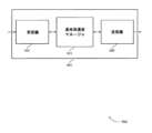
図2は、本開示の様々な態様による、低レイテンシワイヤレス通信におけるアップリンク送信技法をサポートする、ワイヤレス通信サブシステム200の一例を示す。いくつかの例では、ワイヤレス通信サブシステム200は、ワイヤレス通信システム100の態様を実装し得る。図2の例では、ワイヤレス通信サブシステム200は、図1の基地局105の一例であり得る基地局105-aを含み得る。ワイヤレス通信サブシステム200はまた、基地局105-aのカバレージエリア110-a内に位置する、図1のUE115の一例であり得るUE115-aを含み得る。
FIG. 2 illustrates an example
図2の例では、基地局105-aおよびUE115-aは、接続205を確立し得る。場合によっては、基地局105-aは、周期的SPSリソース210を使用し得るSPS送信のために、UE115-aを構成し得る。本明細書で示すように、SPSは、パケットサイズが比較的小さく、到着時間の間が一定であるサービス(たとえば、ボイスオーバーインターネットプロトコル(VoIP)サービス、スケジュールされた周期的ベースにおいて送信し得るある機器のサービスなど)をサポートするために使用され得る。そのようなサービスをサポートするために、各送信のために物理ダウンリンク制御チャネル(PDCCH)送信を使用して、リソースの許可を送ることは無駄であり、したがって、各送信のためにリソース許可と関連情報とを別個に送信することを回避し得る、SPSが構成され得る。UE115-aがSPSを用いて構成されるとき、SPS無線ネットワーク一時識別子(RNTI)、HARQプロセスの数、周期性などのいくつかのパラメータが、SPS構成の一部として、RRCシグナリングを介して示される。次いで、UE115-aは、そのCRCがUE115-a SPS-RNTIによってスクランブルされるPDCCHを介して、明示的にアクティブ化され得る。
In the example of FIG. 2, base station 105-a and UE 115-a may establish
いくつかの展開では、いくつかのDCIフォーマットが、SPSを構成およびアクティブ化するために使用され得る(たとえば、LTEでは、フォーマット0が、ULにおいてSPSをアクティブ化/リリースするために使用され得、フォーマット1/1A/2/2A/2B/2C/2Dが、DLにおいてSPSをアクティブ化するために使用され得、フォーマット1Aが、DLにおいてSPSをリリースするために使用され得る)。場合によっては、アクティベーション/リリース検証のために、いくつかのフィールドが、アクティベーション/リリースのためのFARを低下させ得るあらかじめ定義された値のパターンを有するような、特定の方法において設定されるべきである、DCIコンテンツにおけるいくつかのパラメータがある。場合によっては、SPSは、Pcell上でのみアクティブ化され得る。ロングTTIを使用するSPS送信では、ダウンリンク許可における物理アップリンク制御チャネル(PUCCH)のための送信電力制御が、PUCCHリソース割振りのために使用され、PUCCH電力およびPUSCH電力が、(閉ループ電力制御として動作し得る)いくつかのタイプのDCIにおける電力コマンドによって制御され得る。いくつかのLTE展開では、パラメータtpc-Indexが、TPC-PDCCH-Config情報要素(IE)の一部として、RRCによって各UEのために構成され、ビット文字列内の電力制御コマンドを発見するために使用され得る。
In some deployments, several DCI formats may be used to configure and activate SPS (e.g., in LTE,
本開示の様々な態様では、SPSは、sTTI送信のために提供され得る。ただし、特定のsTTIに関連付けられたDCIは、共通探索空間を有していないことがあり、したがって、SPSがアクティブ化されるとき、ロングTTI SPSアクティベーションのためにあることになるような、ULにおける電力制御のためのsTTI固有の機構がない。場合によっては、UE115-aは、ロングTTI PDCCH送信におけるDCIを介して、PDCCH共通探索空間において送られた電力制御コマンドに依拠し得る。場合によっては、SPS送信のための電力制御は、非SPS送信およびロングTTI送信のための電力制御とは無関係に実行され得る。そのようなSPS sTTI電力制御を達成するために、1つまたは複数のパラメータが、SPS sTTI電力制御を示すPDCCH DCI送信中に含まれ得る。いくつかの例では、1つまたは複数のパラメータは、TPC-PDCCH-Config IE中に含まれ得る。たとえば、パラメータtpc-Index-sTTIが、TPC-PDCCH-Config IEに追加され得、それが、1つまたは複数の定義されたDCIフォーマット(たとえば、DCIフォーマット3/3A)のペイロード内のコマンド文字列内の所与のUEのための電力制御コマンドを取得するために使用される。 In various aspects of this disclosure, SPS may be provided for sTTI transmission. However, the DCIs associated with a particular sTTI may not have a common search space, and therefore when SPS is activated, the UL There is no sTTI-specific mechanism for power control in In some cases, UE 115-a may rely on power control commands sent in the PDCCH common search space via the DCI in long TTI PDCCH transmissions. In some cases, power control for SPS transmissions may be performed independently of power control for non-SPS transmissions and long TTI transmissions. To achieve such SPS sTTI power control, one or more parameters may be included in the PDCCH DCI transmission indicating SPS sTTI power control. In some examples, one or more parameters may be included in the TPC-PDCCH-Config IE. For example, the parameter tpc-Index-sTTI may be added to the TPC-PDCCH-Config IE, which is a command string in the payload of one or more defined DCI formats (e.g., DCI format 3/3A). used to obtain power control commands for a given UE within the UE.
sTTIベースのSPSがアクティブ化されると、UE115-aは、あらゆるサブフレームの共通探索空間を監視し、検出された場合、確立された電力制御コマンド(たとえば、DCIフォーマット3/3Aにおける電力制御コマンド)に従って、そのSPS sPUCCH/sPUSCH電力を修正し得る。そのような方法で、sTTIを使用するSPS送信のための電力制御が通信され得、UE115-aは、送信タイプ(たとえば、SPS送信または非SPS送信)およびTTI持続時間のために適切な電力制御に従って、アップリンク送信を送信し得る。場合によっては、UE115-aは、DCIを受信した後、次の連続サブフレームにおいて電力制御を適用し得る。これは他の手順とは異なることがあり、他の例では、電力制御コマンドがサブフレームn中で受信される場合、コマンドは、定義された数のサブフレームだけ後とは対照的に、サブフレームn+4に適用され得る。一例では、定義された数のサブフレームは、DCIを受信した後の1つのサブフレーム(たとえば、DCIを受信した後の次のサブフレーム)であり得る。いくつかの例では、コマンドは、DCIを受信した後の任意の数のサブフレームに適用され得る。場合によっては、DCIは、レガシーPDCCH領域において送信され得る。 When sTTI-based SPS is activated, the UE115-a monitors the common search space of every subframe and, if detected, detects the established power control commands (e.g., power control commands in DCI format 3/3A). ) may modify its SPS sPUCCH/sPUSCH power. In such a manner, power control for SPS transmissions using sTTI may be communicated, and the UE 115-a communicates the power control appropriate for the transmission type (e.g., SPS transmission or non-SPS transmission) and TTI duration. The uplink transmission may be sent according to the following. In some cases, UE 115-a may apply power control in the next consecutive subframe after receiving the DCI. This may differ from other procedures; in other examples, if a power control command is received during subframe n, the command is May be applied to frame n+4. In one example, the defined number of subframes may be one subframe after receiving the DCI (eg, the next subframe after receiving the DCI). In some examples, the command may be applied to any number of subframes after receiving the DCI. In some cases, DCI may be transmitted in the legacy PDCCH region.
場合によっては、基地局105-aはまた、sTTIを使用するSPS送信において基準信号を送信(たとえば、DMRS送信)するための情報を、UE115-aに提供し得る。場合によっては、基準信号情報は、送信された基準信号に適用されることになるサイクリックシフトを含み得、それによって、基地局がSPS送信のために2つ以上のUEに重複するリソースを割り振ることが可能になり得る。 In some cases, base station 105-a may also provide information to UE 115-a to transmit reference signals in SPS transmissions using sTTI (eg, DMRS transmissions). In some cases, the reference signal information may include a cyclic shift to be applied to the transmitted reference signal, thereby causing the base station to allocate overlapping resources to two or more UEs for SPS transmission. It may become possible.
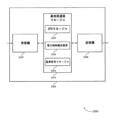
図3は、本開示の様々な態様による、低レイテンシワイヤレス通信におけるアップリンク送信技法をサポートする、ワイヤレスリソース300の一例を示す。いくつかの例では、ワイヤレスリソース300は、ワイヤレス通信システム100の態様を実装し得る。この場合、ワイヤレスリソース300は、2つの1ms TTI、すなわち、TTI-0 305およびTTI-1 310にわたり得る。基地局は、sTTI SPSのための送信電力制御(TPC)315を送信し得る。場合によっては、スケジューリングベースのsPUSCH/sPUCCH、およびSPSベースのsPUSCH/sPUCCHのための閉ループ電力制御機構が、別個に保たれ得、通常のsTTI TPCコマンド320が送信され得る。UEは、TPCコマンド315に基づいて、sTTI SPS sPUSCH送信325を送信し得る。
FIG. 3 illustrates an
本明細書で述べたように、場合によっては、アップリンクSPSは、DCIフォーマット(たとえば、DCIフォーマット0)を介してアクティブ化され得る。したがって、場合によっては、DCIフォーマット3/3Aを介して受信された電力制御コマンドが、UL SPSに適用され得る。場合によっては、アクティブ化DCIは、(1)そのCRCがSPS-CRNTIによってスクランブルされる、(2)NDIが0に設定される、および(3)特殊なSPSアクティベーションPDCCH検証が、あらかじめ決定されたパターンに従って設定される場合、有効である。場合によっては、フィールドのうちの1つは、DMRSのためのサイクリックシフトであり、000に設定される。このために、基地局が複数のUEを区別するための方法がないので、複数のUEが、同じ周波数リソースを割り当てられないことがある。したがって、場合によっては、競合ベースのアップリンク送信を可能にするために、FARを低く保ちながら、基地局は、依然としてDMRS CSフィールドを固定されるように設定し得るが、各UEのためのDMRS送信のためのサイクリックシフトは、関連付けられたUEのためのSPS構成の一部として与えられ得る。 As mentioned herein, in some cases, uplink SPS may be activated via a DCI format (eg, DCI format 0). Therefore, in some cases, power control commands received via DCI format 3/3A may be applied to UL SPS. In some cases, an activated DCI has (1) its CRC scrambled by SPS-CRNTI, (2) NDI set to 0, and (3) special SPS activation PDCCH validation that is predetermined. It is valid if it is set according to the specified pattern. In some cases, one of the fields is the cyclic shift for DMRS and is set to 000. Because of this, multiple UEs may not be allocated the same frequency resources since there is no way for the base station to distinguish between multiple UEs. Therefore, in some cases, to enable contention-based uplink transmission, the base station may still set the DMRS CS field to be fixed while keeping the FAR low, but the DMRS CS field for each UE is Cyclic shifts for transmission may be provided as part of the SPS configuration for the associated UE.
図4は、本開示の様々な態様による、低レイテンシワイヤレス通信におけるアップリンク送信技法をサポートする、プロセスフロー400の一例を示す。いくつかの例では、プロセスフロー400は、ワイヤレス通信システム100の態様を実装し得る。プロセスフロー400は、UE115-bと基地局105-bとの間のSPSの構成および送信を含み得る。基地局105-bは、図1または図2の基地局105の一例であり得、UE115-bは、図1または図2のUE115の一例であり得る。初めに、基地局105-bおよびUE115-bは、接続405を確立し得る。そのような接続確立は、確立された接続確立技法を使用して実行され得る。場合によっては、接続405は、広帯域接続帯域幅を有し得る。
FIG. 4 illustrates an
410で、基地局105-bは、UE115-bのためのSPSリソースを割り振り得る。SPSリソースは、SPS送信のために使用され得るsTTIリソースであり得る。場合によっては、基地局105-bは、UE115-bが後続のDCI送信における電力制御情報を識別するためのインデックス値、基準信号にサイクリックシフトを適用するために使用され得るサイクリックシフト情報、HARQプロセスの数、SPS周期性など、SPS送信に関連付けられた構成情報を識別し得る。基地局105-bは、UE115-bにSPS構成415を送信し得る。420で、UE115-bは、基地局105-bから受信されるSPS構成に従って、SPSを構成し得る。
At 410, base station 105-b may allocate SPS resources for UE 115-b. SPS resources may be sTTI resources that may be used for SPS transmission. In some cases, the base station 105-b provides an index value for the UE 115-b to identify power control information in subsequent DCI transmissions, cyclic shift information that may be used to apply a cyclic shift to the reference signal, Configuration information associated with SPS transmissions may be identified, such as number of HARQ processes, SPS periodicity, etc. Base station 105-b may transmit an
425で、基地局105-bは、SPS sTTI送信のためのTPCを決定し得る。TPCは、場合によっては、LTEにおいて使用される、確立された閉ループ電力制御技法など、閉ループ電力制御技法に従って決定され得る。基地局105-bは、UE115-bに、TPCとともにDCI430を送信し得る。440で、基地局は、SPSをアクティブ化することを決定し得、UE115-bに、SPSアクティベーションとともにDCI445を送信し得る。
At 425, base station 105-b may determine a TPC for SPS sTTI transmission. TPC may in some cases be determined according to a closed-loop power control technique, such as the established closed-loop power control technique used in LTE. Base station 105-b may transmit
UE115-bは、435で、DCI430を受信し、UE SPS構成に基づいて、TPCを識別し得る。場合によっては、SPS構成は、DCI430において送信されるTPC情報のセットへのポインタとして使用され得る、UE115-bのためのインデックスを含み得る。次いで、UE115-bは、SPSアクティベーションとともにDCI445を受信し得、450で、SPSアップリンク送信をフォーマットし得る。場合によっては、UE115-bは、SPS送信においてDMRSを送信し得、455で、UE115-b SPS構成の一部であるサイクリックシフトを適用することによって、DMRSをフォーマットし得る。いくつかの例では、UE115-bは、構成情報に従って、アクティベーションコマンドに応答して、TTIのうちの1つまたは複数における送信のために、DMRSを構成し得る。さらに、UE115-bは、DMRSにサイクリックシフトを適用し得、ここにおいて、構成情報がサイクリックシフトを示す。次いで、UE115-bは、構成されたSPSリソースに従って、sTTIを使用する1つまたは複数のSPSアップリンク送信460を送信し得る。基地局105-bは、465で、チャネル推定のために、およびUEを区別するために、ならびに、SPS送信を送信中であるUEを識別するために、DMRSを使用して、DMRSに基づいてSPSを復号し得る。場合によっては、基地局105-bは、SPSに加えて、sTTIに関連付けられたDCIにおいて提供され得、UE115-bが受信し、sTTIの送信のために使用し得る、スケジューリングベースのsTTI ULリソース割振りをUE115-bに提供し得る。場合によっては、基地局105-bによって提供されたTPCコマンドは、sPUCCH送信とsPUSCH送信の両方に適用され得る。
UE 115-b may receive 435 the
図5は、本開示の態様による、低レイテンシワイヤレス通信におけるアップリンク送信技法をサポートするワイヤレスデバイス505のブロック図500を示す。ワイヤレスデバイス505は、本明細書で説明するようなUE115の態様の一例であり得る。ワイヤレスデバイス505は、受信機510と、UE通信マネージャ515と、送信機520とを含み得る。ワイヤレスデバイス505はまた、プロセッサを含み得る。これらの構成要素の各々は、(たとえば、1つまたは複数のバスを介して)互いに通信中であり得る。
FIG. 5 depicts a block diagram 500 of a
受信機510は、パケット、ユーザデータ、または様々な情報チャネル(たとえば、制御チャネル、データチャネル、および低レイテンシワイヤレス通信におけるアップリンク送信技法に関する情報など)に関連付けられた制御情報など、情報を受信し得る。情報はデバイスの他の構成要素に受け渡され得る。受信機510は、図8を参照しながら説明するトランシーバ835の態様の一例であり得る。受信機510は、単一のアンテナまたはアンテナのセットを利用し得る。
UE通信マネージャ515は、図8を参照しながら説明するUE通信マネージャ815の態様の一例であり得る。
UE通信マネージャ515および/またはその様々な下位構成要素のうちの少なくともいくつかは、ハードウェア、プロセッサによって実行されるソフトウェア、ファームウェア、またはそれらの任意の組合せで実装され得る。プロセッサによって実行されるソフトウェアで実装される場合、UE通信マネージャ515および/またはその様々な下位構成要素のうちの少なくともいくつかの機能は、汎用プロセッサ、デジタル信号プロセッサ(DSP)、特定用途向け集積回路(ASIC)、フィールドプログラマブルゲートアレイ(FPGA)もしくは他のプログラマブル論理デバイス、個別ゲートもしくはトランジスタ論理、個別ハードウェア構成要素、または本開示で説明する機能を実行するように設計されたそれらの任意の組合せによって実行され得る。UE通信マネージャ515および/またはその様々な下位構成要素のうちの少なくともいくつかは、機能の部分が1つまたは複数の物理デバイスによって異なる物理的ロケーションにおいて実装されるように分散されることを含めて、様々な位置に物理的に位置し得る。いくつかの例では、UE通信マネージャ515および/またはその様々な下位構成要素のうちの少なくともいくつかは、本開示の様々な態様による別個のおよび異なる構成要素であり得る。他の例では、UE通信マネージャ515および/またはその様々な下位構成要素のうちの少なくともいくつかは、限定はしないが、I/O構成要素、トランシーバ、ネットワークサーバ、別のコンピューティングデバイス、本開示で説明する1つもしくは複数の他の構成要素、または本開示の様々な態様によるそれらの組合せを含む、1つまたは複数の他のハードウェア構成要素と組み合わせられ得る。
At least some of the
UE通信マネージャ515は、第1のTTIのセットにおいてアップリンク送信を送信するためのSPSアクティベーションを受信することであって、ここで、第1のTTIのセットが、第2のTTIのセットの第2のTTI持続時間よりも短い第1のTTI持続時間を有する、こと、第2のTTIのセットのうちの第1のTTIの間に、第1のTTIのセットのうちの少なくとも1つのTTIのための第1のアップリンク送信電力を設定するための第1のアップリンク電力制御情報と、第2のTTIのセットのうちの少なくとも1つのTTIのための第2のアップリンク送信電力を設定するための第2のアップリンク電力制御情報とを受信すること、および、第1のTTIのセットのうちの少なくとも1つのTTIのための第1のアップリンク電力を設定することを行い得る。
The
一例では、UE通信マネージャ515はまた、UEにおいて、第1のTTIのセットにおいてアップリンク送信を送信するためのSPS構成を受信することであって、ここで、第1のTTIのセットが、第2のTTIのセットの第2のTTI持続時間よりも短い第1のTTI持続時間を有し、ここで、SPS構成が、第1のTTIのセットのうちの1つまたは複数において送信されたDMRSに適用されることになる構成情報を含む、こと、第2のTTIのセットのうちの第1のTTIの間に、SPS構成をアクティブ化するためのアクティベーションコマンドを受信すること、アクティベーションコマンドに応答して、第1のTTIのセットのうちの1つまたは複数における送信のために、DMRSをフォーマットすること、および、DMRSにサイクリックシフトを適用することを行い得る。他の場合には、UEは、構成情報に従って、アクティベーションコマンドに応答して、TTIのうちの1つまたは複数における送信のために、DMRSを構成し得、第1のTTIのセットのうちの少なくとも1つにおいて、構成されたDMRSを送信し得る。さらに、UEは、DMRSにサイクリックシフトを適用し得、ここにおいて、構成情報が少なくともサイクリックシフトを示す。別の例では、UE通信マネージャ515はまた、UEにおいて、第1のTTIのセットにおいてアップリンク送信を送信するためのSPS構成を受信することであって、ここで、第1のTTIのセットが、第2のTTIのセットの第2のTTI持続時間よりも短い第1のTTI持続時間を有し、ここで、SPS構成が、第1のTTIのセットのうちの1つまたは複数において送信されたDMRSのために構成されることになる構成情報を含む、こと、第2のTTIのセットのうちの第1のTTIの間に、SPSをアクティブ化するためのアクティベーションコマンドを受信すること、アクティベーションコマンドに応答して、第1のTTIのセットのうちの1つまたは複数における送信のために、DMRSをフォーマットすること、および、DMRSのための情報を構成することを行い得る。
In one example, the
送信機520は、デバイスの他の構成要素によって生成された信号を送信し得る。いくつかの例では、送信機520は、トランシーバモジュール内で受信機510と併置され得る。たとえば、送信機520は、図8を参照しながら説明するトランシーバ835の態様の一例であり得る。送信機520は、単一のアンテナまたはアンテナのセットを利用し得る。
送信機520は、第1のアップリンク電力を使用して、SPS許可に従って、第1のTTIのセットのうちの少なくとも1つのTTIを送信し、第1のTTIのセットのうちの少なくとも1つにおいて、サイクリックシフトされたDMRSを送信し得る。
図6は、本開示の態様による、低レイテンシワイヤレス通信におけるアップリンク送信技法をサポートするワイヤレスデバイス605のブロック図600を示す。ワイヤレスデバイス605は、図5を参照しながら説明したような、ワイヤレスデバイス505またはUE115の態様の一例であり得る。ワイヤレスデバイス605は、受信機610と、UE通信マネージャ615と、送信機620とを含み得る。ワイヤレスデバイス605はまた、1つまたは複数のプロセッサと、1つまたは複数のプロセッサと結合されたメモリと、本明細書で説明する特徴を1つまたは複数のプロセッサが実行することを可能にするために、1つまたは複数のプロセッサによって実行可能である、メモリに記憶された命令とを含み得る。これらの構成要素の各々は、(たとえば、1つまたは複数のバスを介して)互いに通信中であり得る。
FIG. 6 depicts a block diagram 600 of a
受信機610は、パケット、ユーザデータ、または様々な情報チャネル(たとえば、制御チャネル、データチャネル、および低レイテンシワイヤレス通信におけるアップリンク送信技法に関する情報など)に関連付けられた制御情報など、情報を受信し得る。情報はデバイスの他の構成要素に受け渡され得る。受信機610は、図8を参照しながら説明するトランシーバ835の態様の一例であり得る。受信機610は、単一のアンテナまたはアンテナのセットを利用し得る。
UE通信マネージャ615は、図8を参照しながら説明するUE通信マネージャ815の態様の一例であり得る。場合によっては、UE通信マネージャ615は、プロセッサ(たとえば、トランシーバプロセッサ、または無線機プロセッサ、または受信機プロセッサ)であり得る。プロセッサは、メモリと結合され得、本明細書で説明する特徴をプロセッサが実行するかまたは容易にすることを可能にする、メモリに記憶された命令を実行し得る。UE通信マネージャ615はまた、SPSマネージャ625と、DCIマネージャ630と、電力制御構成要素635と、基準信号マネージャ640とを含み得る。
SPSマネージャ625は、第1のTTIのセットにおいてアップリンク送信を送信するためのSPSアクティベーションを受信することであって、ここで、第1のTTIのセットが、第2のTTIのセットの第2のTTI持続時間よりも短い第1のTTI持続時間を有する、ことを行い得る。場合によっては、SPSマネージャ625はプロセッサであり得る。プロセッサは、メモリと結合され得、本明細書で説明する特徴をプロセッサが実行するかまたは容易にすることを可能にする、メモリに記憶された命令を実行し得る。場合によっては、SPSマネージャ625は、第2のTTIのセットのうちの第1のTTIにおいて提供された異なる電力制御情報のセットから、第1のアップリンク電力制御情報を識別するためのインデックス値を受信し得る。場合によっては、SPSマネージャ625は、SPS構成において、第1のTTIのセットのうちの1つまたは複数において送信されたDMRSに適用されることになる、サイクリックシフトを受信し得る。場合によっては、複数のUEが、非直交のSPSリソースを用いて構成される。場合によっては、アクティベーションコマンドは、UEがSPS構成に従ってサイクリックシフトを適用中であるときに無視される、DMRSサイクリックシフトを示すフィールドを含む。
The
DCIマネージャ630は、第2のTTIのセットのうちの第1のTTIの間に、第1のTTIのセットのうちの少なくとも1つのTTIのための第1のアップリンク送信電力を設定するための第1のアップリンク電力制御情報と、第2のTTIのセットのうちの少なくとも1つのTTIのための第2のアップリンク送信電力を設定するための第2のアップリンク電力制御情報とを受信し得る。場合によっては、DCIマネージャ630はプロセッサであり得る。プロセッサは、メモリと結合され得、本明細書で説明する特徴をプロセッサが実行するかまたは容易にすることを可能にする、メモリに記憶された命令を実行し得る。場合によっては、第1のアップリンク電力制御情報および第2のアップリンク電力制御情報は、DCIにおいて送信される。場合によっては、DCIは、DCIフォーマット3/3Aを使用する。場合によっては、アクティベーションコマンドにおいて示されたDMRSサイクリックシフトは、アクティベーションコマンドの信頼性を高め、アクティベーションコマンドのためのFARを低減するために使用される。場合によっては、アクティベーションコマンドは、基地局からのDCIにおいて受信される。場合によっては、DCIは、SPSをアクティブ化するためのあらかじめ決定されたDCIフォーマット、すなわち、DCIフォーマット0を有する。場合によっては、アクティベーションコマンドのCRCが、UEにおいて構成されるSPS識別情報によってスクランブルされること、および、DMRSサイクリックシフトフィールドを含む、DCIの1つまたは複数のフィールドが、あらかじめ決定されたパターンの値に設定されることを検証することによって、アクティベーションコマンドが確認される。場合によっては、DCIは、フォーマット3またはフォーマット3aのいずれか一方であり得、DCIは、レガシーLTE PDCCH領域において送信され得る。
電力制御構成要素635は、第1のTTIのセットのうちの少なくとも1つのTTIのための第1のアップリンク電力を設定し得る。場合によっては、電力制御構成要素635はプロセッサであり得る。プロセッサは、メモリと結合され得、本明細書で説明する特徴をプロセッサが実行するかまたは容易にすることを可能にする、メモリに記憶された命令を実行し得る。場合によっては、第1のTTIのセットのためのアップリンク電力制御は、第2のTTIのセットのためのアップリンク電力制御とは無関係に実行される。場合によっては、第1のTTIのセットのためのアップリンク電力制御は、第1のTTI持続時間を有する第3のTTIのセットのためのアップリンク電力制御とは無関係に実行される。場合によっては、第1のTTIのセットのうちの少なくとも1つのTTIは、第1のアップリンク電力制御情報の受信から、次の連続サブフレームだけ後に来るサブフレームにおいて、第1のアップリンク電力を使用して送信される。
基準信号マネージャ640は、アクティベーションコマンドに応答して、第1のTTIのセットのうちの1つまたは複数における送信のために、DMRSをフォーマットすること、および、DMRSにサイクリックシフトを適用することを行い得る。場合によっては、基準信号マネージャ640はプロセッサであり得る。プロセッサは、メモリと結合され得、本明細書で説明する特徴をプロセッサが実行するかまたは容易にすることを可能にする、メモリに記憶された命令を実行し得る。一例では、基準信号マネージャ640は、アクティベーションコマンドに応答して、第1のTTIのセットのうちの1つまたは複数における送信のために、DMRSをフォーマットすること、および、DMRSのための情報を構成することを行い得る。場合によっては、基準信号マネージャ640は、構成情報に従って、アクティベーションコマンドに応答して、第1の複数のTTIのうちの1つまたは複数における送信のために、DMRSを構成し得、第1のTTIのセットのうちの少なくとも1つにおいて、構成されたDMRSを送信し得る。
送信機620は、デバイスの他の構成要素によって生成された信号を送信し得る。いくつかの例では、送信機620は、トランシーバモジュール内で受信機610と併置され得る。たとえば、送信機620は、図8を参照しながら説明するトランシーバ835の態様の一例であり得る。送信機620は、単一のアンテナまたはアンテナのセットを利用し得る。
図7は、本開示の態様による、低レイテンシワイヤレス通信におけるアップリンク送信技法をサポートするUE通信マネージャ715のブロック図700を示す。UE通信マネージャ715は、図5、図6、および図8を参照しながら説明する、UE通信マネージャ515、UE通信マネージャ615、またはUE通信マネージャ815の態様の一例であり得る。UE通信マネージャ715は、SPSマネージャ720と、DCIマネージャ725と、電力制御構成要素730と、基準信号マネージャ735と、RRCマネージャ740とを含み得る。これらのモジュールの各々は、直接または間接的に(たとえば、1つまたは複数のバスを介して)互いに通信し得る。
FIG. 7 depicts a block diagram 700 of a
SPSマネージャ720は、第1のTTIのセットにおいてアップリンク送信を送信するためのSPSアクティベーションを受信することであって、ここで、第1のTTIのセットが、第2のTTIのセットの第2のTTI持続時間よりも短い第1のTTI持続時間を有する、ことを行い得る。場合によっては、SPSマネージャ720はプロセッサであり得る。プロセッサは、メモリと結合され得、本明細書で説明する特徴をプロセッサが実行するかまたは容易にすることを可能にする、メモリに記憶された命令を実行し得る。場合によっては、SPSマネージャ720は、第2のTTIのセットのうちの第1のTTIにおいて提供された異なる電力制御情報のセットから、第1のアップリンク電力制御情報を識別するためのインデックス値を受信し得る。場合によっては、SPSマネージャ720は、SPS構成において、第1のTTIのセットのうちの1つまたは複数において送信されたDMRSに適用されることになる、サイクリックシフトを受信し得る。場合によっては、複数のUEが、非直交のSPSリソースを用いて構成される。場合によっては、アクティベーションコマンドは、UEがSPS構成に従ってサイクリックシフトを適用中であるときに無視される、DMRSサイクリックシフトを示すフィールドを含む。
The
DCIマネージャ725は、第2のTTIのセットのうちの第1のTTIの間に、第1のTTIのセットのうちの少なくとも1つのTTIのための第1のアップリンク送信電力を設定するための第1のアップリンク電力制御情報と、第2のTTIのセットのうちの少なくとも1つのTTIのための第2のアップリンク送信電力を設定するための第2のアップリンク電力制御情報とを受信し得る。場合によっては、DCIマネージャ725はプロセッサであり得る。プロセッサは、メモリと結合され得、本明細書で説明する特徴をプロセッサが実行するかまたは容易にすることを可能にする、メモリに記憶された命令を実行し得る。場合によっては、第1のアップリンク電力制御情報および第2のアップリンク電力制御情報は、DCIにおいて送信される。場合によっては、DCIは、DCIフォーマット3/3Aを使用する。場合によっては、アクティベーションコマンドにおいて示されたDMRSサイクリックシフトは、アクティベーションコマンドの信頼性を高め、アクティベーションコマンドのためのFARを低減するために使用される。場合によっては、アクティベーションコマンドは、基地局からのDCIにおいて受信される。場合によっては、DCIは、SPSをアクティブ化するためのあらかじめ決定されたDCIフォーマット、すなわち、DCIフォーマット0を有する。場合によっては、アクティベーションコマンドのCRCが、UEにおいて構成されるSPS識別情報によってスクランブルされること、および、DMRSサイクリックシフトフィールドを含む、DCIの1つまたは複数のフィールドが、あらかじめ決定されたパターンの値に設定されることを検証することによって、アクティベーションコマンドが確認される。
The
電力制御構成要素730は、第1のTTIのセットのうちの少なくとも1つのTTIのための第1のアップリンク電力を設定し得る。場合によっては、電力制御構成要素730はプロセッサであり得る。プロセッサは、メモリと結合され得、本明細書で説明する特徴をプロセッサが実行するかまたは容易にすることを可能にする、メモリに記憶された命令を実行し得る。場合によっては、第1のTTIのセットのためのアップリンク電力制御は、第2のTTIのセットのためのアップリンク電力制御とは無関係に実行される。場合によっては、第1のTTIのセットのためのアップリンク電力制御は、第1のTTI持続時間を有する第3のTTIのセットのためのアップリンク電力制御とは無関係に実行される。場合によっては、第1のTTIのセットのうちの少なくとも1つのTTIは、第1のアップリンク電力制御情報の受信から、次の連続サブフレームだけ後に来るサブフレームにおいて、第1のアップリンク電力を使用して送信される。
基準信号マネージャ735は、アクティベーションコマンドに応答して、第1のTTIのセットのうちの1つまたは複数における送信のために、DMRSをフォーマットすること、および、DMRSにサイクリックシフトを適用することを行い得る。場合によっては、基準信号マネージャ735はプロセッサであり得る。プロセッサは、メモリと結合され得、本明細書で説明する特徴をプロセッサが実行するかまたは容易にすることを可能にする、メモリに記憶された命令を実行し得る。一例では、基準信号マネージャ735は、アクティベーションコマンドに応答して、第1のTTIのセットのうちの1つまたは複数における送信のために、DMRSをフォーマットすること、および、DMRSのための情報を構成することを行い得る。場合によっては、基準信号マネージャ735は、構成情報に従って、アクティベーションコマンドに応答して、第1の複数のTTIのうちの1つまたは複数における送信のために、DMRSを構成し得、第1のTTIのセットのうちの少なくとも1つにおいて、構成されたDMRSを送信し得る。
RRCマネージャ740は、RRCシグナリングを受信および処理し得る。場合によっては、インデックス値は、RRCシグナリングを介して、構成情報要素において受信される。場合によっては、RRCマネージャ740はプロセッサであり得る。プロセッサは、メモリと結合され得、本明細書で説明する特徴をプロセッサが実行するかまたは容易にすることを可能にする、メモリに記憶された命令を実行し得る。場合によっては、インデックス値は、TPC-PDCCH-Config情報要素におけるtpc-Index-sTTIフィールドにおいて受信される。場合によっては、インデックス値は、PUSCHおよびPUCCHについて別個に設定され得る。
図8は、本開示の態様による、低レイテンシワイヤレス通信におけるアップリンク送信技法をサポートする、デバイス805を含むシステム800の図を示す。デバイス805は、たとえば、図5および図6を参照しながら本明細書で説明したようなワイヤレスデバイス505、ワイヤレスデバイス605、またはUE115の構成要素の一例であるか、またはそれらを含み得る。デバイス805は、UE通信マネージャ815と、プロセッサ820と、メモリ825と、ソフトウェア830と、トランシーバ835と、アンテナ840と、I/Oコントローラ845とを含む、通信を送信および受信するための構成要素を含む、双方向音声およびデータ通信のための構成要素を含み得る。これらの構成要素は、1つまたは複数のバス(たとえば、バス810)を介して電子通信中であり得る。デバイス805は、1つまたは複数の基地局105とワイヤレス通信し得る。
FIG. 8 depicts a diagram of a
プロセッサ820は、インテリジェントハードウェアデバイス(たとえば、汎用プロセッサ、DSP、中央処理装置(CPU)、マイクロコントローラ、ASIC、FPGA、プログラマブル論理デバイス、個別ゲートもしくはトランジスタ論理構成要素、個別ハードウェア構成要素、またはそれらの任意の組合せ)を含み得る。場合によっては、プロセッサ820は、メモリコントローラを使用してメモリアレイを動作させるように構成され得る。他の場合には、メモリコントローラは、プロセッサ820の中に統合され得る。プロセッサ820は、様々な機能(たとえば、低レイテンシワイヤレス通信におけるアップリンク送信技法をサポートする機能またはタスク)を実行するために、メモリに記憶されたコンピュータ可読命令を実行するように構成され得る。
メモリ825は、ランダムアクセスメモリ(RAM)および読取り専用メモリ(ROM)を含み得る。メモリ825は、実行されると、本明細書で説明する様々な機能をプロセッサに実行させる命令を含む、コンピュータ可読、コンピュータ実行可能ソフトウェア830を記憶し得る。場合によっては、メモリ825は、特に、周辺構成要素または周辺デバイスとの対話などの基本的なハードウェア動作またはソフトウェア動作を制御し得る基本入出力システム(BIOS)を含み得る。
ソフトウェア830は、低レイテンシワイヤレス通信におけるアップリンク送信技法をサポートするためのコードを含む、本開示の態様を実装するためのコードを含み得る。ソフトウェア830は、システムメモリまたは他のメモリなどの非一時的コンピュータ可読媒体内に記憶され得る。場合によっては、ソフトウェア830は、プロセッサによって直接実行可能でない場合があるが、(たとえば、コンパイルおよび実行されると)本明細書で説明する機能をコンピュータに実行させ得る。
トランシーバ835は、本明細書で説明するような1つまたは複数のアンテナ、ワイヤードリンク、またはワイヤレスリンクを介して双方向に通信することができる。たとえば、トランシーバ835はワイヤレストランシーバを表すことがあり、別のワイヤレストランシーバと双方向に通信し得る。トランシーバ835はまた、パケットを変調し、変調されたパケットを送信のためにアンテナに与え、かつアンテナから受信されたパケットを復調するためのモデムを含み得る。
場合によっては、ワイヤレスデバイスは、単一のアンテナ840を含み得る。ただし、場合によっては、デバイスは、2つ以上のアンテナ840を有することがあり、2つ以上のアンテナ840は、複数のワイヤレス送信を並行して送信または受信することが可能であり得る。
In some cases, a wireless device may include a
I/Oコントローラ845は、デバイス805のための入力および出力の信号を管理し得る。I/Oコントローラ845はまた、デバイス805に統合されていない周辺装置を管理し得る。場合によっては、I/Oコントローラ845は、外部周辺装置への物理的接続またはポートを表し得る。場合によっては、I/Oコントローラ845は、iOS(登録商標)、ANDROID(登録商標)、MS-DOS(登録商標)、MS-WINDOWS(登録商標)、OS/2(登録商標)、UNIX(登録商標)、LINUX(登録商標)、または別の知られているオペレーティングシステムなどのオペレーティングシステムを利用し得る。他の場合には、I/Oコントローラ845は、モデム、キーボード、マウス、タッチスクリーン、または同様のデバイスを表し、またはそれと対話し得る。場合によっては、I/Oコントローラ845は、プロセッサの一部として実装され得る。場合によっては、ユーザは、I/Oコントローラ845を介して、またはI/Oコントローラ845によって制御されたハードウェア構成要素を介して、デバイス805と対話し得る。
I/
図9は、本開示の態様による、低レイテンシワイヤレス通信におけるアップリンク送信技法をサポートするワイヤレスデバイス905のブロック図900を示す。ワイヤレスデバイス905は、本明細書で説明するような基地局105の態様の一例であり得る。ワイヤレスデバイス905は、受信機910と、基地局通信マネージャ915と、送信機920とを含み得る。ワイヤレスデバイス905はまた、1つまたは複数のプロセッサと、1つまたは複数のプロセッサと結合されたメモリと、本明細書で説明する特徴を1つまたは複数のプロセッサが実行することを可能にするために、1つまたは複数のプロセッサによって実行可能である、メモリに記憶された命令とを含み得る。これらの構成要素の各々は、(たとえば、1つまたは複数のバスを介して)互いに通信中であり得る。
FIG. 9 illustrates a block diagram 900 of a
受信機910は、パケット、ユーザデータ、または様々な情報チャネル(たとえば、制御チャネル、データチャネル、および低レイテンシワイヤレス通信におけるアップリンク送信技法に関する情報など)に関連付けられた制御情報など、情報を受信し得る。情報はデバイスの他の構成要素に受け渡され得る。受信機910は、図12を参照しながら説明するトランシーバ1235の態様の一例であり得る。受信機910は、単一のアンテナまたはアンテナのセットを利用し得る。
受信機910は、第1のTTIのセットにおいて、1つまたは複数のアップリンク送信を受信することであって、1つまたは複数のアップリンク送信が、DMRS送信を含む、ことを行い得る。
基地局通信マネージャ915は、図12を参照しながら説明する基地局通信マネージャ1215の態様の一例であり得る。
Base
基地局通信マネージャ915および/またはその様々な下位構成要素のうちの少なくともいくつかは、ハードウェア、プロセッサによって実行されるソフトウェア、ファームウェア、またはそれらの任意の組合せで実装され得る。プロセッサによって実行されるソフトウェアで実装される場合、基地局通信マネージャ915および/またはその様々な下位構成要素のうちの少なくともいくつかの機能は、汎用プロセッサ、DSP、ASIC、FPGAもしくは他のプログラマブル論理デバイス、個別ゲートもしくはトランジスタ論理、個別ハードウェア構成要素、または本開示で説明する機能を実行するように設計されたそれらの任意の組合せによって実行され得る。基地局通信マネージャ915および/またはその様々な下位構成要素のうちの少なくともいくつかは、機能の部分が1つまたは複数の物理デバイスによって異なる物理的ロケーションにおいて実装されるように分散されることを含めて、様々な位置に物理的に位置し得る。いくつかの例では、基地局通信マネージャ915および/またはその様々な下位構成要素のうちの少なくともいくつかは、本開示の様々な態様による別個のおよび異なる構成要素であり得る。他の例では、基地局通信マネージャ915および/またはその様々な下位構成要素のうちの少なくともいくつかは、限定はしないが、I/O構成要素、トランシーバ、ネットワークサーバ、別のコンピューティングデバイス、本開示で説明する1つもしくは複数の他の構成要素、または本開示の様々な態様によるそれらの組合せを含む、1つまたは複数の他のハードウェア構成要素と組み合わせられ得る。
Base
基地局通信マネージャ915は、UEに、第1のTTIのセットにおいてアップリンク送信を送信するためのSPSアクティベーションを送信することであって、ここで、第1のTTIのセットが、第2のTTIのセットの第2のTTI持続時間よりも短い第1のTTI持続時間を有する、こと、および、第1のTTIのセットのうちの少なくとも1つのTTIのためのUEにおける第1のアップリンク送信電力を設定するための第1のアップリンク電力制御情報と、第2のTTIのセットのうちの少なくとも1つのTTIのための第2のアップリンク送信電力を設定するための第2のアップリンク電力制御情報とを決定することを行い得る。
The base
一例では、基地局通信マネージャ915はまた、UEに、第1のTTIのセットにおいて、UEからのアップリンク送信のためのSPS構成を送信することであって、ここで、第1のTTIのセットが、第2のTTIのセットの第2のTTI持続時間よりも短い第1のTTI持続時間を有し、ここで、SPS構成が、第1のTTIのセットのうちの1つまたは複数において送信されたDMRSに適用されることになるサイクリックシフト(および、いくつかの例では、構成情報)を含む、こと、第2のTTIのセットのうちの第1のTTIの間に、SPSをアクティブ化するために、UEにアクティベーションコマンドを送信すること、DMRSにサイクリックシフトを適用すること、および、サイクリックシフトされたDMRSに基づいて、1つまたは複数のアップリンク送信を復号することを行い得る。別の例では、基地局通信マネージャ915はまた、UEに、第1のTTIのセットにおいて、UEからのアップリンク送信のためのSPS構成を送信することであって、ここで、第1のTTIのセットが、第2のTTIのセットの第2のTTI持続時間よりも短い第1のTTI持続時間を有し、ここで、SPS構成が、第1のTTIのセットのうちの1つまたは複数において送信されたDMRSに適用されることになる構成情報を含む、こと、第2のTTIのセットのうちの第1のTTIの間に、SPSをアクティブ化するために、UEにアクティベーションコマンドを送信すること、構成情報に従って、DMRSを処理すること、および、処理されたDMRSに基づいて、1つまたは複数のアップリンク送信を復号することを行い得る。
In one example, the base
送信機920は、デバイスの他の構成要素によって生成された信号を送信し得る。いくつかの例では、送信機920は、トランシーバモジュール内で受信機910と併置され得る。たとえば、送信機920は、図12を参照しながら説明するトランシーバ1235の態様の一例であり得る。送信機920は、単一のアンテナまたはアンテナのセットを利用し得る。
送信機920は、第2のTTIのセットのうちの第1のTTIの間に、UEに第1のアップリンク電力制御情報と、第2のアップリンク電力制御情報とを送信し得る。
図10は、本開示の態様による、低レイテンシワイヤレス通信におけるアップリンク送信技法をサポートするワイヤレスデバイス1005のブロック図1000を示す。ワイヤレスデバイス1005は、図9を参照しながら説明したような、ワイヤレスデバイス905または基地局105の態様の一例であり得る。ワイヤレスデバイス1005は、受信機1010と、基地局通信マネージャ1015と、送信機1020とを含み得る。ワイヤレスデバイス1005はまた、プロセッサを含み得る。これらの構成要素の各々は、(たとえば、1つまたは複数のバスを介して)互いに通信中であり得る。
FIG. 10 illustrates a block diagram 1000 of a
受信機1010は、パケット、ユーザデータ、または様々な情報チャネル(たとえば、制御チャネル、データチャネル、および低レイテンシワイヤレス通信におけるアップリンク送信技法に関する情報など)に関連付けられた制御情報など、情報を受信し得る。情報はデバイスの他の構成要素に受け渡され得る。受信機1010は、図12を参照しながら説明するトランシーバ1235の態様の一例であり得る。受信機1010は、単一のアンテナまたはアンテナのセットを利用し得る。
基地局通信マネージャ1015は、図12を参照しながら説明する基地局通信マネージャ1215の態様の一例であり得る。
Base
基地局通信マネージャ1015はまた、SPSマネージャ1025と、電力制御構成要素1030と、基準信号マネージャ1035とを含み得る。
Base
SPSマネージャ1025は、UEに、第1のTTIのセットにおいてアップリンク送信を送信するためのSPSアクティベーションを送信し得る。場合によっては、SPSマネージャ1025はプロセッサであり得る。プロセッサは、メモリと結合され得、本明細書で説明する特徴をプロセッサが実行するかまたは容易にすることを可能にする、メモリに記憶された命令を実行し得る。場合によっては、SPSマネージャ1025は、第2のTTIのセットのうちの第1のTTIにおいて提供された異なる電力制御情報のセットから、第1のアップリンク電力制御情報を識別するためのインデックス値を用いて、UEを構成することであって、ここで、第1のTTIのセットが、第2のTTIのセットの第2のTTI持続時間よりも短い第1のTTI持続時間を有する、ことを行い得る。場合によっては、SPSマネージャ1025は、UEに、第1のTTIのセットにおいて、UEからのアップリンク送信のためのSPS構成を送信することであって、ここで、SPS構成が、第1のTTIのセットのうちの1つまたは複数において送信されたDMRSに適用されることになるサイクリックシフトを含む、ことを行い得る。SPSマネージャ1025はまた、第2のTTIのセットのうちの第1のTTIの間に、SPSをアクティブ化するために、UEにアクティベーションコマンドを送信し得る。場合によっては、複数のUEが、非直交のSPSリソースを用いて構成される。
電力制御構成要素1030は、第1のTTIのセットのうちの少なくとも1つのTTIのためのUEにおける第1のアップリンク送信電力を設定するための第1のアップリンク電力制御情報と、第2のTTIのセットのうちの少なくとも1つのTTIのための第2のアップリンク送信電力を設定するための第2のアップリンク電力制御情報とを決定し得る。場合によっては、電力制御構成要素1030はプロセッサであり得る。プロセッサは、メモリと結合され得、本明細書で説明する特徴をプロセッサが実行するかまたは容易にすることを可能にする、メモリに記憶された命令を実行し得る。場合によっては、第1のTTIのセットのためのアップリンク電力制御は、第2のTTIのセットのためのアップリンク電力制御とは無関係に実行される。場合によっては、第1のTTIのセットのためのアップリンク電力制御は、第1のTTI持続時間を有する第3のTTIのセットのためのアップリンク電力制御とは無関係に実行される。
基準信号マネージャ1035は、構成情報に従って、DMRSを処理すること、および、処理されたDMRSに基づいて、1つまたは複数のアップリンク送信を復号することを行う。場合によっては、基準信号マネージャ1035はプロセッサであり得る。プロセッサは、メモリと結合され得、本明細書で説明する特徴をプロセッサが実行するかまたは容易にすることを可能にする、メモリに記憶された命令を実行し得る。
送信機1020は、デバイスの他の構成要素によって生成された信号を送信し得る。いくつかの例では、送信機1020は、トランシーバモジュール内で受信機1010と併置され得る。たとえば、送信機1020は、図12を参照しながら説明するトランシーバ1235の態様の一例であり得る。送信機1020は、単一のアンテナまたはアンテナのセットを利用し得る。
図11は、本開示の態様による、低レイテンシワイヤレス通信におけるアップリンク送信技法をサポートする基地局通信マネージャ1115のブロック図1100を示す。基地局通信マネージャ1115は、図9、図10、および図12を参照しながら説明する、基地局通信マネージャ1215の態様の一例であり得る。基地局通信マネージャ1115は、SPSマネージャ1120と、電力制御構成要素1125と、基準信号マネージャ1130と、DCIマネージャ1135と、RRCマネージャ1140とを含み得る。これらのモジュールの各々は、直接または間接的に(たとえば、1つまたは複数のバスを介して)互いに通信し得る。
FIG. 11 depicts a block diagram 1100 of a base
SPSマネージャ1120は、UEに、第1のTTIのセットにおいてアップリンク送信を送信するためのSPSアクティベーションを送信し得る。場合によっては、SPSマネージャ1120はプロセッサであり得る。プロセッサは、メモリと結合され得、本明細書で説明する特徴をプロセッサが実行するかまたは容易にすることを可能にする、メモリに記憶された命令を実行し得る。場合によっては、SPSマネージャ1120は、第2のTTIのセットのうちの第1のTTIにおいて提供された異なる電力制御情報のセットから、第1のアップリンク電力制御情報を識別するためのインデックス値を用いて、UEを構成することであって、ここで、第1のTTIのセットが、第2のTTIのセットの第2のTTI持続時間よりも短い第1のTTI持続時間を有する、ことを行い得る。場合によっては、SPSマネージャ1120は、UEに、第1のTTIのセットにおいて、UEからのアップリンク送信のためのSPS構成を送信することであって、ここで、SPS構成が、第1のTTIのセットのうちの1つまたは複数において送信されたDMRSに適用されることになるサイクリックシフトを含む、ことを行い得る。SPSマネージャ1120はまた、第2のTTIのセットのうちの第1のTTIの間に、SPSをアクティブ化するために、UEにアクティベーションコマンドを送信し得る。場合によっては、複数のUEが、非直交のSPSリソースを用いて構成される。
電力制御構成要素1125は、第1のTTIのセットのうちの少なくとも1つのTTIのためのUEにおける第1のアップリンク送信電力を設定するための第1のアップリンク電力制御情報と、第2のTTIのセットのうちの少なくとも1つのTTIのための第2のアップリンク送信電力を設定するための第2のアップリンク電力制御情報とを決定し得る。場合によっては、電力制御構成要素1125はプロセッサであり得る。プロセッサは、メモリと結合され得、本明細書で説明する特徴をプロセッサが実行するかまたは容易にすることを可能にする、メモリに記憶された命令を実行し得る。場合によっては、第1のTTIのセットのためのアップリンク電力制御は、第2のTTIのセットのためのアップリンク電力制御とは無関係に実行される。場合によっては、第1のTTIのセットのためのアップリンク電力制御は、第1のTTI持続時間を有する第3のTTIのセットのためのアップリンク電力制御とは無関係に実行される。
基準信号マネージャ1130は、構成情報に従って、DMRSを処理し得、いくつかの例では、構成情報において示されたDMRSにサイクリックシフトを適用し、処理されたDMRSに基づいて、1つまたは複数のアップリンク送信を復号し得る。場合によっては、基準信号マネージャ1130はプロセッサであり得る。プロセッサは、メモリと結合され得、本明細書で説明する特徴をプロセッサが実行するかまたは容易にすることを可能にする、メモリに記憶された命令を実行し得る。
DCIマネージャ1135は、DCIを識別し、1つまたは複数のUEにDCIを送信し得る。場合によっては、DCIマネージャ1135はプロセッサであり得る。プロセッサは、メモリと結合され得、本明細書で説明する特徴をプロセッサが実行するかまたは容易にすることを可能にする、メモリに記憶された命令を実行し得る。場合によっては、第1のアップリンク電力制御情報および第2のアップリンク電力制御情報は、DCIにおいて送信される。場合によっては、アクティベーションコマンドは、DMRSにサイクリックシフトを適用するときにUEによって無視されるDMRSサイクリックシフトを示すフィールドを含む。RRCマネージャ1140は、RRCシグナリングを管理し得る。場合によっては、インデックス値は、RRCシグナリングを介して、構成情報要素において、UEに送信される。
図12は、本開示の態様による、低レイテンシワイヤレス通信におけるアップリンク送信技法をサポートする、デバイス1205を含むシステム1200の図を示す。デバイス1205は、たとえば、図1を参照しながら本明細書で説明したような基地局105の構成要素の一例であるか、またはそれらを含み得る。デバイス1205は、基地局通信マネージャ1215と、プロセッサ1220と、メモリ1225と、ソフトウェア1230と、トランシーバ1235と、アンテナ1240と、ネットワーク通信マネージャ1245と、局間通信マネージャ1250とを含む、通信を送信および受信するための構成要素を含む、双方向音声およびデータ通信のための構成要素を含み得る。これらの構成要素は、1つまたは複数のバス(たとえば、バス1210)を介して電子通信中であり得る。デバイス1205は、1つまたは複数のUE115とワイヤレス通信し得る。
FIG. 12 depicts a diagram of a
プロセッサ1220は、インテリジェントハードウェアデバイス(たとえば、汎用プロセッサ、DSP、CPU、マイクロコントローラ、ASIC、FPGA、プログラマブル論理デバイス、個別ゲートもしくはトランジスタ論理構成要素、個別ハードウェア構成要素、またはそれらの任意の組合せ)を含み得る。場合によっては、プロセッサ1220は、メモリコントローラを使用してメモリアレイを動作させるように構成され得る。他の場合には、メモリコントローラは、プロセッサ1220の中に統合され得る。プロセッサ1220は、様々な機能(たとえば、低レイテンシワイヤレス通信におけるアップリンク送信技法をサポートする機能またはタスク)を実行するために、メモリに記憶されたコンピュータ可読命令を実行するように構成され得る。
メモリ1225は、RAMおよびROMを含み得る。メモリ1225は、実行されると、本明細書で説明する様々な機能をプロセッサに実行させる命令を含む、コンピュータ可読、コンピュータ実行可能ソフトウェア1230を記憶し得る。場合によっては、メモリ1225は、特に、周辺構成要素または周辺デバイスとの相互作用など、基本的なハードウェア動作またはソフトウェア動作を制御し得るBIOSを含み得る。
ソフトウェア1230は、低レイテンシワイヤレス通信におけるアップリンク送信技法をサポートするためのコードを含む、本開示の態様を実装するためのコードを含み得る。ソフトウェア1230は、システムメモリまたは他のメモリなどの非一時的コンピュータ可読媒体内に記憶され得る。場合によっては、ソフトウェア1230は、プロセッサによって直接実行可能でない場合があるが、(たとえば、コンパイルおよび実行されると)本明細書で説明する機能をコンピュータに実行させ得る。
トランシーバ1235は、本明細書で説明するような1つまたは複数のアンテナ、ワイヤードリンク、またはワイヤレスリンクを介して双方向に通信することができる。たとえば、トランシーバ1235は、ワイヤレストランシーバを表すことがあり、別のワイヤレストランシーバと双方向に通信し得る。トランシーバ1235はまた、パケットを変調し、変調されたパケットを送信のためにアンテナに与え、かつアンテナから受信されたパケットを復調するためのモデムを含み得る。
場合によっては、ワイヤレスデバイスは、単一のアンテナ1240を含み得る。ただし、場合によっては、デバイスは、2つ以上のアンテナ1240を有することがあり、2つ以上のアンテナ1240は、複数のワイヤレス送信を並行して送信または受信することが可能であり得る。
In some cases, the wireless device may include a
ネットワーク通信マネージャ1245は、(たとえば、1つまたは複数のワイヤードバックホールリンクを介して)コアネットワークとの通信を管理し得る。たとえば、ネットワーク通信マネージャ1245は、1つまたは複数のUE115など、クライアントデバイスのためのデータ通信の転送を管理し得る。
局間通信マネージャ1250は、他の基地局105との通信を管理し得、他の基地局105と協調してUE115との通信を制御するためのコントローラまたはスケジューラを含んでよい。たとえば、局間通信マネージャ1250は、ビームフォーミングまたはジョイント送信などの様々な干渉軽減技法のために、UE115への送信に対するスケジューリングを協調させ得る。いくつかの例では、局間通信マネージャ1250は、基地局105間の通信を行うために、ロングタームエボリューション(LTE)/LTE-Aワイヤレス通信ネットワーク技術内のX2インターフェースを提供し得る。
図13は、本開示の態様による、低レイテンシワイヤレス通信におけるアップリンク送信技法のための方法1300を示すフローチャートを示す。方法1300の動作は、本明細書で説明するように、UE115またはその構成要素によって実施され得る。たとえば、方法1300の動作は、図5~図8を参照しながら説明したように、UE通信マネージャによって実行され得る。いくつかの例では、UE115は、以下で説明する機能を実行するようにデバイスの機能要素を制御するためのコードのセットを実行し得る。追加または代替として、UE115は、専用ハードウェアを使用して、以下で説明する機能の態様を実行し得る。
FIG. 13 depicts a flowchart illustrating a
1305で、UE115は、第1の複数のTTIにおいてアップリンク送信を送信するためのSPSアクティベーションを受信することであって、第1の複数のTTIが、第2の複数のTTIの第2のTTI持続時間よりも短い第1のTTI持続時間を有する、ことを行い得る。1305の動作は、本明細書で説明する方法に従って実行され得る。いくつかの例では、1305の動作の態様は、図5~図8を参照しながら説明したように、SPSマネージャによって実行され得る。
At 1305, the
1310で、UE115は、第2の複数のTTIのうちの第1のTTIの間に、第1の複数のTTIのうちの少なくとも1つのTTIのための第1のアップリンク送信電力を設定するための第1のアップリンク電力制御情報と、第2の複数のTTIのうちの少なくとも1つのTTIのための第2のアップリンク送信電力を設定するための第2のアップリンク電力制御情報とを受信し得る。1310の動作は、本明細書で説明する方法に従って実行され得る。いくつかの例では、1310の動作の態様は、図5~図8を参照しながら説明したように、DCIマネージャによって実行され得る。場合によっては、電力制御コマンドは、PUCCHおよびPUSCHについて異なり得、それに応じて、異なるTPCインデックスが構成され得る。
At 1310, the
1315で、UE115は、第1の複数のTTIのうちの少なくとも1つのTTIのための第1のアップリンク電力を設定し得る。1315の動作は、本明細書で説明する方法に従って実行され得る。いくつかの例では、1315の動作の態様は、図5~図8を参照しながら説明したように、電力制御構成要素によって実行され得る。
At 1315, the
1320で、UE115は、第1のアップリンク電力を使用して、SPS許可に従って、第1の複数のTTIのうちの少なくとも1つのTTIを送信し得る。1320の動作は、本明細書で説明する方法に従って実行され得る。いくつかの例では、1320の動作の態様は、図5~図8を参照しながら説明したように、送信機によって実行され得る。
At 1320, the
図14は、本開示の態様による、低レイテンシワイヤレス通信におけるアップリンク送信技法のための方法1400を示すフローチャートを示す。方法1400の動作は、本明細書で説明するように、UE115またはその構成要素によって実施され得る。たとえば、方法1400の動作は、図5~図8を参照しながら説明したように、UE通信マネージャによって実行され得る。いくつかの例では、UE115は、以下で説明する機能を実行するようにデバイスの機能要素を制御するためのコードのセットを実行し得る。追加または代替として、UE115は、専用ハードウェアを使用して、以下で説明する機能の態様を実行し得る。
FIG. 14 depicts a flowchart illustrating a
1405で、UE115は、第2の複数のTTIのうちの第1のTTIにおいて提供された複数の異なる電力制御情報から、第1のアップリンク電力制御情報を識別するためのインデックス値を受信し得る。1405の動作は、本明細書で説明する方法に従って実行され得る。いくつかの例では、1405の動作の態様は、図5~図8を参照しながら説明したように、SPSマネージャによって実行され得る。
At 1405, the
1410で、UE115は、第1の複数のTTIにおいてアップリンク送信を送信するためのSPSアクティベーションを受信することであって、第1の複数のTTIが、第2の複数のTTIの第2のTTI持続時間よりも短い第1のTTI持続時間を有する、ことを行い得る。1410の動作は、本明細書で説明する方法に従って実行され得る。いくつかの例では、1410の動作の態様は、図5~図8を参照しながら説明したように、SPSマネージャによって実行され得る。
At 1410, the
1415で、UE115は、第2の複数のTTIのうちの第1のTTIの間に、第1の複数のTTIのうちの少なくとも1つのTTIのための第1のアップリンク送信電力を設定するための第1のアップリンク電力制御情報と、第2の複数のTTIのうちの少なくとも1つのTTIのための第2のアップリンク送信電力を設定するための第2のアップリンク電力制御情報とを受信し得る。1415の動作は、本明細書で説明する方法に従って実行され得る。いくつかの例では、1415の動作の態様は、図5~図8を参照しながら説明したように、DCIマネージャによって実行され得る。
At 1415, the
1420で、UE115は、第1の複数のTTIのうちの少なくとも1つのTTIのための第1のアップリンク電力を設定し得る。1420の動作は、本明細書で説明する方法に従って実行され得る。いくつかの例では、1420の動作の態様は、図5~図8を参照しながら説明したように、電力制御構成要素によって実行され得る。
At 1420, the
1425で、UE115は、第1のアップリンク電力を使用して、SPS許可に従って、第1の複数のTTIのうちの少なくとも1つのTTIを送信し得る。1425の動作は、本明細書で説明する方法に従って実行され得る。いくつかの例では、1425の動作の態様は、図5~図8を参照しながら説明したように、送信機によって実行され得る。
At 1425, the
図15は、本開示の態様による、低レイテンシワイヤレス通信におけるアップリンク送信技法のための方法1500を示すフローチャートを示す。方法1500の動作は、本明細書で説明するように、基地局105またはその構成要素によって実施され得る。たとえば、方法1500の動作は、図9~図12を参照しながら説明したように、基地局通信マネージャによって実行され得る。いくつかの例では、基地局105は、以下で説明する機能を実行するようにデバイスの機能要素を制御するためのコードのセットを実行し得る。追加または代替として、基地局105は、専用ハードウェアを使用して、以下で説明する機能の態様を実行し得る。
FIG. 15 depicts a flowchart illustrating a
1505で、基地局105は、UEに、第1の複数のTTIにおいてアップリンク送信を送信するためのSPSアクティベーションを送信することであって、第1の複数のTTIが、第2の複数のTTIの第2のTTI持続時間よりも短い第1のTTI持続時間を有する、ことを行い得る。1505の動作は、本明細書で説明する方法に従って実行され得る。いくつかの例では、1505の動作の態様は、図9~図12を参照しながら説明したように、SPSマネージャによって実行され得る。
At 1505, the
1510で、基地局105は、第1の複数のTTIのうちの少なくとも1つのTTIのためのUEにおける第1のアップリンク送信電力を設定するための第1のアップリンク電力制御情報と、第2の複数のTTIのうちの少なくとも1つのTTIのための第2のアップリンク送信電力を設定するための第2のアップリンク電力制御情報とを決定し得る。1510の動作は、本明細書で説明する方法に従って実行され得る。いくつかの例では、1510の動作の態様は、図9~図12を参照しながら説明したように、電力制御構成要素によって実行され得る。
At 1510, the
1515で、基地局105は、第2の複数のTTIのうちの第1のTTIの間に、UEに第1のアップリンク電力制御情報と、第2のアップリンク電力制御情報とを送信し得る。1515の動作は、本明細書で説明する方法に従って実行され得る。いくつかの例では、1515の動作の態様は、図9~図12を参照しながら説明したように、送信機によって実行され得る。
At 1515, the
図16は、本開示の態様による、低レイテンシワイヤレス通信におけるアップリンク送信技法のための方法1600を示すフローチャートを示す。方法1600の動作は、本明細書で説明するように、基地局105またはその構成要素によって実施され得る。たとえば、方法1600の動作は、図9~図12を参照しながら説明したように、基地局通信マネージャによって実行され得る。いくつかの例では、基地局105は、以下で説明する機能を実行するようにデバイスの機能要素を制御するためのコードのセットを実行し得る。追加または代替として、基地局105は、専用ハードウェアを使用して、以下で説明する機能の態様を実行し得る。
FIG. 16 depicts a flowchart illustrating a
1605で、基地局105は、第2の複数のTTIのうちの第1のTTIにおいて提供された複数の異なる電力制御情報から、第1のアップリンク電力制御情報を識別するためのインデックス値を用いて、UEを構成し得る。1605の動作は、本明細書で説明する方法に従って実行され得る。いくつかの例では、1605の動作の態様は、図9~図12を参照しながら説明したように、SPSマネージャによって実行され得る。
At 1605, the
1610で、基地局105は、UEに、第1の複数のTTIにおいてアップリンク送信を送信するためのSPSアクティベーションを送信することであって、第1の複数のTTIが、第2の複数のTTIの第2のTTI持続時間よりも短い第1のTTI持続時間を有する、ことを行い得る。1610の動作は、本明細書で説明する方法に従って実行され得る。いくつかの例では、1610の動作の態様は、図9~図12を参照しながら説明したように、SPSマネージャによって実行され得る。
At 1610, the
1615で、基地局105は、第1の複数のTTIのうちの少なくとも1つのTTIのためのUEにおける第1のアップリンク送信電力を設定するための第1のアップリンク電力制御情報と、第2の複数のTTIのうちの少なくとも1つのTTIのための第2のアップリンク送信電力を設定するための第2のアップリンク電力制御情報とを決定し得る。1615の動作は、本明細書で説明する方法に従って実行され得る。いくつかの例では、1615の動作の態様は、図9~図12を参照しながら説明したように、電力制御構成要素によって実行され得る。
At 1615, the
1620で、基地局105は、第2の複数のTTIのうちの第1のTTIの間に、UEに第1のアップリンク電力制御情報と、第2のアップリンク電力制御情報とを送信し得る。1620の動作は、本明細書で説明する方法に従って実行され得る。いくつかの例では、1620の動作の態様は、図9~図12を参照しながら説明したように、送信機によって実行され得る。
At 1620, the
図17は、本開示の態様による、低レイテンシワイヤレス通信におけるアップリンク送信技法のための方法1700を示すフローチャートを示す。方法1700の動作は、本明細書で説明するように、UE115またはその構成要素によって実施され得る。たとえば、方法1700の動作は、図5~図8を参照しながら説明したように、UE通信マネージャによって実行され得る。いくつかの例では、UE115は、以下で説明する機能を実行するようにデバイスの機能要素を制御するためのコードのセットを実行し得る。追加または代替として、UE115は、専用ハードウェアを使用して、以下で説明する機能の態様を実行し得る。
FIG. 17 depicts a flowchart illustrating a
1705で、UE115は、UEにおいて、第1の複数のTTIにおいてアップリンク送信を送信するためのSPS構成を受信することであって、第1の複数のTTIが、第2の複数のTTIの第2のTTI持続時間よりも短い第1のTTI持続時間を有し、SPS構成が、第1の複数のTTIのうちの1つまたは複数において送信されたDMRSに適用されることになるサイクリックシフトを含む、ことを行い得る。1705の動作は、本明細書で説明する方法に従って実行され得る。いくつかの例では、1705の動作の態様は、図5~図8を参照しながら説明したように、SPSマネージャによって実行され得る。
At 1705, the
1710で、UE115は、第2の複数のTTIのうちの第1のTTIの間に、SPSをアクティブ化するためのアクティベーションコマンドを受信し得る。1710の動作は、本明細書で説明する方法に従って実行され得る。いくつかの例では、1710の動作の態様は、図5~図8を参照しながら説明したように、SPSマネージャによって実行され得る。
At 1710, the
1715で、UE115は、構成情報に従って、アクティベーションコマンドに応答して、第1の複数のTTIのうちの1つまたは複数における送信のために、DMRSを構成し得る。いくつかの例では、UE115は、構成情報において示されたDMRSに、サイクリックシフトを適用し得る。1715の動作は、本明細書で説明する方法に従って実行され得る。いくつかの例では、1715の動作の態様は、図5~図8を参照しながら説明したように、基準信号マネージャによって実行され得る。
At 1715, the
1720で、UE115は、第1のTTIのセットのうちの少なくとも1つにおいて、構成されたDMRSを送信し得る。いくつかの例では、UE115は、第1の複数のTTIのうちの少なくとも1つにおいて、サイクリックシフトされたDMRSを送信し得る。1720の動作は、本明細書で説明する方法に従って実行され得る。いくつかの例では、1720の動作の態様は、図5~図8を参照しながら説明したように、送信機によって実行され得る。
At 1720, the
図18は、本開示の態様による、低レイテンシワイヤレス通信におけるアップリンク送信技法のための方法1800を示すフローチャートを示す。方法1800の動作は、本明細書で説明するように、基地局105またはその構成要素によって実施され得る。たとえば、方法1800の動作は、図9~図12を参照しながら説明したように、基地局通信マネージャによって実行され得る。いくつかの例では、基地局105は、以下で説明する機能を実行するようにデバイスの機能要素を制御するためのコードのセットを実行し得る。追加または代替として、基地局105は、専用ハードウェアを使用して、以下で説明する機能の態様を実行し得る。
FIG. 18 depicts a flowchart illustrating a
1805で、基地局105は、UEに、第1の複数のTTIにおいて、UEからのアップリンク送信のためのSPS構成を送信することであって、第1の複数のTTIが、第2の複数のTTIの第2のTTI持続時間よりも短い第1のTTI持続時間を有し、SPS構成が、第1の複数のTTIのうちの1つまたは複数において送信されたDMRSに適用されることになるサイクリックシフトを含む、ことを行い得る。1805の動作は、本明細書で説明する方法に従って実行され得る。いくつかの例では、1805の動作の態様は、図9~図12を参照しながら説明したように、SPSマネージャによって実行され得る。
At 1805, the
1810で、基地局105は、第2の複数のTTIのうちの第1のTTIの間に、SPSをアクティブ化するために、UEにアクティベーションコマンドを送信し得る。1810の動作は、本明細書で説明する方法に従って実行され得る。いくつかの例では、1810の動作の態様は、図9~図12を参照しながら説明したように、SPSマネージャによって実行され得る。
At 1810, the
1815で、基地局105は、第1の複数のTTIにおいて、1つまたは複数のアップリンク送信を受信することであって、1つまたは複数のアップリンク送信が、DMRS送信を含む、ことを行い得る。1815の動作は、本明細書で説明する方法に従って実行され得る。いくつかの例では、1815の動作の態様は、図9~図12を参照しながら説明したように、受信機によって実行され得る。
At 1815, the
1820で、基地局105は、構成情報に従って、DMRSを処理し得る。いくつかの例では、基地局105は、チャネル推定を行い、ユーザを区別するために、構成情報において示されたDMRSのサイクリックシフトを適用し得る。1820の動作は、本明細書で説明する方法に従って実行され得る。いくつかの例では、1820の動作の態様は、図9~図12を参照しながら説明したように、基準信号マネージャによって実行され得る。
At 1820,
1825で、基地局105は、処理されたDMRSに少なくとも部分的に基づいて、1つまたは複数のアップリンク送信を復号し得る。1825の動作は、本明細書で説明する方法に従って実行され得る。いくつかの例では、1825の動作の態様は、図9~図12を参照しながら説明したように、基準信号マネージャによって実行され得る。
At 1825,
本明細書で説明する方法は可能な実装形態を表すこと、動作およびステップが再構成されるかまたは場合によっては変更され得ること、ならびに他の実装形態が可能であることに留意されたい。さらに、方法のうちの2つ以上からの態様が組み合わせられ得る。 Note that the methods described herein represent possible implementations, that the operations and steps may be rearranged or modified in some cases, and that other implementations are possible. Additionally, aspects from two or more of the methods may be combined.
本明細書で説明する技法は、符号分割多元接続(CDMA)システム、時分割多元接続(TDMA)システム、周波数分割多元接続(FDMA)システム、直交周波数分割多元接続(OFDMA)システム、シングルキャリア周波数分割多元接続(SC-FDMA)システム、および他のシステムなど、様々なワイヤレス通信システムのために使用され得る。CDMAシステムは、CDMA2000、ユニバーサル地上波無線アクセス(UTRA)などの無線技術を実装し得る。CDMA2000は、IS-2000規格、IS-95規格、およびIS-856規格をカバーする。IS-2000リリースは、一般に、CDMA2000 1X、1Xなどと呼ばれることがある。IS-856(TIA-856)は、一般に、CDMA2000 1xEV-DO、高速パケットデータ(HRPD)などと呼ばれる。UTRAは、広帯域CDMA(WCDMA(登録商標))およびCDMAの他の変形態を含む。TDMAシステムは、モバイル通信用グローバルシステム(GSM)などの無線技術を実装し得る。 The techniques described herein can be applied to code division multiple access (CDMA) systems, time division multiple access (TDMA) systems, frequency division multiple access (FDMA) systems, orthogonal frequency division multiple access (OFDMA) systems, single carrier frequency division It may be used for a variety of wireless communication systems, such as multiple access (SC-FDMA) systems, and other systems. A CDMA system may implement a radio technology such as CDMA2000, Universal Terrestrial Radio Access (UTRA). CDMA2000 covers IS-2000, IS-95, and IS-856 standards. IS-2000 releases are sometimes commonly referred to as CDMA2000 1X, 1X, etc. IS-856 (TIA-856) is generally called CDMA2000 1xEV-DO, high-speed packet data (HRPD), etc. UTRA includes wideband CDMA (WCDMA) and other variants of CDMA. A TDMA system may implement a radio technology such as Global System for Mobile Communications (GSM).
OFDMAシステムは、ウルトラモバイルブロードバンド(UMB)、発展型UTRA(E-UTRA)、電気電子技術者協会(IEEE)802.11(Wi-Fi)、および、限定はしないが、802.11b、802.11g、802.11a、802.11n、802.11ac、802.11ad、802.11ah、802.11ax、802.11ay、802.11baなどを含むバージョン、IEEE 802.16(WiMAX)、IEEE 802.20、Flash-OFDMなどの無線技術を実装し得る。UTRAおよびE-UTRAは、ユニバーサルモバイルテレコミュニケーションズシステム(UMTS)の一部である。LTEおよびLTE-Aは、E-UTRAを使用するUMTSのリリースである。UTRA、E-UTRA、UMTS、LTE、LTE-A、NR、およびGSMは、「第3世代パートナーシッププロジェクト」(3GPP)という名称の組織からの文書に記載されている。CDMA2000およびUMBは、「第3世代パートナーシッププロジェクト2」(3GPP2)という名称の組織からの文書に記載されている。本明細書で説明する技法は、本明細書で述べたシステムおよび無線技術ならびに他のシステムおよび無線技術のために使用されてよい。LTEまたはNRシステムの態様が例として説明され得、LTEまたはNR用語が説明の大部分において使用され得るが、本明細書で説明する技法は、LTEまたはNR適用例以外に適用可能である。 OFDMA systems include Ultra Mobile Broadband (UMB), Evolved UTRA (E-UTRA), Institute of Electrical and Electronics Engineers (IEEE) 802.11 (Wi-Fi), and, but not limited to, 802.11b, 802.11g, 802.11a. , versions including 802.11n, 802.11ac, 802.11ad, 802.11ah, 802.11ax, 802.11ay, 802.11ba, etc., may implement wireless technologies such as IEEE 802.16 (WiMAX), IEEE 802.20, Flash-OFDM, etc. UTRA and E-UTRA are part of the Universal Mobile Telecommunications System (UMTS). LTE and LTE-A are releases of UMTS that use E-UTRA. UTRA, E-UTRA, UMTS, LTE, LTE-A, NR, and GSM are listed in a document from an organization named ``3rd Generation Partnership Project'' (3GPP). CDMA2000 and UMB are described in documents from an organization named "3rd Generation Partnership Project 2" (3GPP2). The techniques described herein may be used for the systems and wireless technologies described herein as well as other systems and wireless technologies. Although aspects of LTE or NR systems may be described as examples, and LTE or NR terminology may be used in much of the description, the techniques described herein are applicable to other than LTE or NR applications.
マクロセルは、一般に、比較的大きい地理的エリア(たとえば、半径数キロメートル)をカバーし、ネットワークプロバイダのサービスに加入しているUE115による無制限アクセスを可能にし得る。スモールセルは、マクロセルと比較して低電力の基地局105に関連付けられることがあり、スモールセルは、マクロセルと同じまたはマクロセルとは異なる(たとえば、認可、無認可など)周波数帯域において動作することがある。スモールセルは、様々な例によれば、ピコセル、フェムトセル、およびマイクロセルを含み得る。ピコセルは、たとえば、小さい地理的エリアをカバーし得、ネットワークプロバイダのサービスに加入しているUE115による無制限アクセスを可能にし得る。フェムトセルも、小さい地理的エリア(たとえば、自宅)をカバーし得、フェムトセルとの関連付けを有するUE115(たとえば、限定加入者グループ(CSG)内のUE115、自宅内のユーザのためのUE115など)による制限付きアクセスを提供し得る。マクロセルのためのeNBは、マクロeNBと呼ばれることがある。スモールセルのためのeNBは、スモールセルeNB、ピコeNB、フェムトeNB、またはホームeNBと呼ばれることがある。eNBは、1つまたは複数の(たとえば、2つ、3つ、4つなどの)セルをサポートし得、1つまたは複数のコンポーネントキャリアを使用する通信もサポートし得る。
A macro cell typically covers a relatively large geographic area (eg, several kilometers radius) and may allow unrestricted access by
本明細書で説明する1つまたは複数のワイヤレス通信システム100は、同期動作または非同期動作をサポートしてもよい。同期動作の場合、基地局105は、同様のフレームタイミングを有することがあり、異なる基地局105からの送信は、時間的にほぼ揃えられることがある。非同期動作の場合、基地局105は、異なるフレームタイミングを有することがあり、異なる基地局105からの送信は、時間的に揃えられないことがある。本明細書で説明する技法は、同期動作または非同期動作のいずれかのために使用され得る。
One or more
本明細書で説明する情報および信号は、多種多様な技術および技法のいずれを使用して表されてもよい。たとえば、上記の説明全体にわたって言及され得るデータ、命令、コマンド、情報、信号、ビット、シンボル、およびチップは、電圧、電流、電磁波、磁場もしくは磁性粒子、光場もしくは光学粒子、またはそれらの任意の組合せによって表されてよい。 The information and signals described herein may be represented using any of a variety of different technologies and techniques. For example, data, instructions, commands, information, signals, bits, symbols, and chips that may be referred to throughout the above description refer to voltages, electrical currents, electromagnetic waves, magnetic fields or magnetic particles, light fields or optical particles, or any of the following. May be represented by a combination.
本明細書の本開示に関して説明した様々な例示的なブロックおよびモジュールは、汎用プロセッサ、デジタル信号プロセッサ(DSP)、特定用途向け集積回路(ASIC)、フィールドプログラマブルゲートアレイ(FPGA)もしくは他のプログラマブル論理デバイス(PLD)、個別ゲートもしくはトランジスタ論理、個別ハードウェア構成要素、または本明細書で説明する機能を実行するように設計されたそれらの任意の組合せを用いて実装または実行され得る。汎用プロセッサはマイクロプロセッサであり得るが、代替的には、プロセッサは、任意の従来のプロセッサ、コントローラ、マイクロコントローラ、またはステートマシンであり得る。プロセッサはまた、コンピューティングデバイスの組合せ(たとえば、DSPとマイクロプロセッサの組合せ、複数のマイクロプロセッサ、DSPコアと連携する1つもしくは複数のマイクロプロセッサ、または任意の他のそのような構成)として実装され得る。 Various exemplary blocks and modules described herein with respect to the present disclosure may include general purpose processors, digital signal processors (DSPs), application specific integrated circuits (ASICs), field programmable gate arrays (FPGAs) or other programmable logic devices. It may be implemented or performed using devices (PLDs), discrete gate or transistor logic, discrete hardware components, or any combination thereof designed to perform the functions described herein. A general purpose processor may be a microprocessor, but in the alternative, the processor may be any conventional processor, controller, microcontroller, or state machine. A processor may also be implemented as a combination of computing devices (e.g., a DSP and microprocessor combination, multiple microprocessors, one or more microprocessors in conjunction with a DSP core, or any other such configuration). obtain.
本明細書で説明する機能は、ハードウェア、プロセッサによって実行されるソフトウェア、ファームウェア、またはそれらの任意の組合せで実装され得る。プロセッサによって実行されるソフトウェアで実装される場合、機能は、1つまたは複数の命令またはコードとして、コンピュータ可読媒体上に記憶されるか、またはコンピュータ可読媒体を介して送信され得る。他の例および実装形態は、本開示および添付の特許請求の範囲の範囲内に入る。たとえば、ソフトウェアの性質に起因して、本明細書で説明する機能は、プロセッサによって実行されるソフトウェア、ハードウェア、ファームウェア、ハードワイヤリング、またはこれらのうちのいずれかの組合せを使用して実装され得る。機能を実装する特徴はまた、機能の部分が、異なる物理的ロケーションにおいて実装されるように分散されることを含めて、様々な位置において物理的に位置し得る。 The functionality described herein may be implemented in hardware, software executed by a processor, firmware, or any combination thereof. If implemented in software executed by a processor, the functions may be stored on or transmitted over as one or more instructions or code on a computer-readable medium. Other examples and implementations are within the scope of this disclosure and the appended claims. For example, due to the nature of software, the functionality described herein may be implemented using software executed by a processor, hardware, firmware, hard wiring, or any combination thereof. . Features implementing the functionality may also be physically located at various locations, including distributed such that portions of the functionality are implemented at different physical locations.
コンピュータ可読媒体は、ある場所から別の場所へのコンピュータプログラムの移送を容易にする任意の媒体を含む、非一時的コンピュータ記憶媒体と通信媒体の両方を含む。非一時的記憶媒体は、汎用コンピュータまたは専用コンピュータによってアクセスされ得る任意の利用可能な媒体であり得る。限定ではなく例として、非一時的コンピュータ可読媒体は、ランダムアクセスメモリ(RAM)、読取り専用メモリ(ROM)、電気的消去可能プログラマブル読取り専用メモリ(EEPROM)、フラッシュメモリ、コンパクトディスク(CD)ROMまたは他の光ディスクストレージ、磁気ディスクストレージまたは他の磁気ストレージデバイス、あるいは、命令またはデータ構造の形態の所望のプログラムコード手段を搬送または記憶するために使用され、汎用もしくは専用コンピュータまたは汎用もしくは専用プロセッサによってアクセスされ得る任意の他の非一時的媒体を備え得る。また、いかなる接続もコンピュータ可読媒体と適切に呼ばれる。たとえば、ソフトウェアが、同軸ケーブル、光ファイバーケーブル、ツイストペア、デジタル加入者回線(DSL)、または赤外線、無線、およびマイクロ波などのワイヤレス技術を使用して、ウェブサイト、サーバ、または他のリモートソースから送信される場合、同軸ケーブル、光ファイバーケーブル、ツイストペア、DSL、または赤外線、無線、およびマイクロ波などのワイヤレス技術は、媒体の定義に含まれる。本明細書で使用するディスク(disk)およびディスク(disc)は、CD、レーザーディスク(登録商標)(disc)、光ディスク(disc)、デジタル多用途ディスク(disc)(DVD)、フロッピーディスク(disk)およびBlu-ray(登録商標)ディスク(disc)を含み、ディスク(disk)は通常、データを磁気的に再生し、ディスク(disc)は、レーザーを用いてデータを光学的に再生する。上記の組合せもコンピュータ可読媒体の範囲内に含まれる。 Computer-readable media includes both non-transitory computer storage media and communication media including any medium that facilitates transfer of a computer program from one place to another. Non-transitory storage media may be any available media that can be accessed by a general purpose or special purpose computer. By way of example and not limitation, non-transitory computer-readable media may include random access memory (RAM), read-only memory (ROM), electrically erasable programmable read-only memory (EEPROM), flash memory, compact disk (CD) ROM, or Any other optical disk storage, magnetic disk storage or other magnetic storage device or used to carry or store desired program code means in the form of instructions or data structures and accessed by a general purpose or special purpose computer or a general purpose or special purpose processor. any other non-transitory medium that may be used. Also, any connection is properly termed a computer-readable medium. For example, if the software is transmitted from a website, server, or other remote source using coaxial cable, fiber optic cable, twisted pair, digital subscriber line (DSL), or wireless technologies such as infrared, radio, and microwave. If so, coaxial cable, fiber optic cable, twisted pair, DSL, or wireless technologies such as infrared, radio, and microwave are included in the definition of medium. As used herein, "disk" and "disc" refer to CD, LaserDisc (registered trademark) (disc), optical disc (disc), digital versatile disc (disc) (DVD), and floppy disk (disk). and Blu-ray discs, which typically reproduce data magnetically and discs which reproduce data optically using a laser. Combinations of the above are also included within the scope of computer-readable media.
特許請求の範囲内を含めて本明細書で使用する場合、項目のリスト(たとえば、「のうちの少なくとも1つ」または「のうちの1つまたは複数」などの句で終わる項目のリスト)において使用する「または」は、たとえば、A、B、またはCのうちの少なくとも1つのリストがAまたはBまたはCまたはABまたはACまたはBCまたはABC(たとえば、AおよびBおよびC)を意味するような包括的リストを示す。また、本明細書で使用する「に基づいて」という句は、条件の閉集合を参照するものと解釈されるべきではない。たとえば、「条件Aに基づいて」として説明した例示的なステップは、本開示の範囲から逸脱することなく、条件Aと条件Bの両方に基づき得る。言い換えれば、本明細書で使用する「に基づいて」という句は、「に少なくとも部分的に基づいて」という句と同じように解釈されるべきである。 As used herein, including in the claims, in a list of items (e.g., a list of items ending with a phrase such as "at least one of" or "one or more of") The use of "or" is used, for example, such that at least one list of A, B, or C means A or B or C or AB or AC or BC or ABC (e.g., A and B and C). A comprehensive list is presented. Additionally, as used herein, the phrase "based on" should not be construed as referring to a closed set of conditions. For example, an exemplary step described as "based on condition A" may be based on both condition A and condition B without departing from the scope of this disclosure. In other words, as used herein, the phrase "based on" should be construed in the same manner as the phrase "based at least in part on."
添付の図では、同様の構成要素または特徴は同じ参照ラベルを有し得る。さらに、同じタイプの様々な構成要素は、参照ラベルの後、ダッシュと、それらの同様の構成要素を区別する第2のラベルとを続けることによって区別され得る。第1の参照ラベルのみが本明細書で使用される場合、説明は、第2の参照ラベル、または他の後続の参照ラベルにかかわらず、同じ第1の参照ラベルを有する同様の構成要素のうちのいずれにも適用可能である。 In the accompanying figures, similar components or features may have the same reference label. Additionally, various components of the same type may be distinguished by following the reference label with a dash and a second label that distinguishes those similar components. When only a first reference label is used herein, the description refers to similar components having the same first reference label, regardless of the second reference label, or any other subsequent reference label. It is applicable to both.
添付の図面に関して本明細書に記載される説明は、例示的な構成について説明しており、実装され得るかまたは特許請求の範囲内に入るすべての例を表すとは限らない。本明細書で使用する「例示的」という用語は、「例、事例、または例示として働くこと」ことを意味し、「好ましい」または「他の例よりも有利な」を意味するものではない。発明を実施するための形態は、説明する技法の理解をもたらすための具体的な詳細を含む。しかしながら、これらの技法は、これらの具体的な詳細なしに実践され得る。いくつかの事例では、説明する例の概念を不明瞭にすることを回避するために、よく知られている構造およびデバイスがブロック図の形態で示される。 The descriptions herein with respect to the accompanying drawings describe example configurations and do not represent all examples that may be implemented or fall within the scope of the claims. As used herein, the term "exemplary" means "serving as an example, instance, or illustration," and does not mean "preferred" or "advantageous over other instances." The detailed description includes specific details to provide an understanding of the described techniques. However, these techniques may be practiced without these specific details. In some instances, well-known structures and devices are shown in block diagram form in order to avoid obscuring the concepts of the described examples.
本明細書の説明は、当業者が本開示を作成または使用することを可能にするように与えられる。本開示への様々な変更は当業者には容易に明らかとなり、本明細書で定義する一般原理は、本開示の範囲から逸脱することなく他の変形形態に適用され得る。したがって、本開示は、本明細書で説明する例および設計に限定されず、本明細書で開示する原理および新規の特徴に合致する最も広い範囲を与えられるべきである。 The description herein is provided to enable any person skilled in the art to make or use the disclosure. Various modifications to this disclosure will be readily apparent to those skilled in the art, and the general principles defined herein may be applied to other variations without departing from the scope of this disclosure. Therefore, this disclosure is not limited to the examples and designs described herein, but is to be accorded the widest scope consistent with the principles and novel features disclosed herein.
100 ワイヤレス通信システム
105、105-a、105-b 基地局
110 地理的カバレージエリア
110-a カバレージエリア
115、115-a、115-b UE
125 通信リンク
130 コアネットワーク
132、134 バックホールリンク
200 ワイヤレス通信サブシステム
205 接続
210 周期的SPSリソース
300 ワイヤレスリソース
305 TTI-0
310 TTI-1
315 sTTI SPSのための送信電力制御(TPC)、TPCコマンド
320 通常のsTTI TPCコマンド
325 sTTI SPS sPUSCH送信
405 接続
415 SPS構成
430、445 DCI
460 SPSアップリンク送信
505、605、905、1005 ワイヤレスデバイス
510、610、910、1010 受信機
515、615、715、815 UE通信マネージャ
520、620、920、1020 送信機
625、720、1025、1120 SPSマネージャ
630、725、1135 DCIマネージャ
635、730、1030、1125 電力制御構成要素
640、735、1035、1130 基準信号マネージャ
740、1140 RRCマネージャ
800、1200 システム
805、1205 デバイス
810、1210 バス
820、1220 プロセッサ
825、1225 メモリ
830、1230 ソフトウェア、コンピュータ可読、コンピュータ実行可能ソフトウェア
835、1235 トランシーバ
840、1240 アンテナ
845 I/Oコントローラ
915、1015、1115、1215 基地局通信マネージャ
1245 ネットワーク通信マネージャ
1250 局間通信マネージャ
100 wireless communication systems
105, 105-a, 105-b base station
110 Geographic coverage area
110-a coverage area
115, 115-a, 115-b UE
125 Communication Link
130 Core Network
132, 134 Backhaul link
200 Wireless Communication Subsystem
205 Connection
210 Periodic SPS resource
300 wireless resources
305 TTI-0
310 TTI-1
315 sTTI Transmit Power Control (TPC) for SPS, TPC commands
320 normal sTTI TPC command
325 sTTI SPS sPUSCH transmission
405 Connection
415 SPS configuration
430, 445 DCI
460 SPS uplink transmission
505, 605, 905, 1005 wireless devices
510, 610, 910, 1010 receiver
515, 615, 715, 815 UE Communication Manager
520, 620, 920, 1020 transmitter
625, 720, 1025, 1120 SPS Manager
630, 725, 1135 DCI Manager
635, 730, 1030, 1125 Power Control Components
640, 735, 1035, 1130 Reference Signal Manager
740, 1140 RRC Manager
800, 1200 system
805, 1205 devices
810, 1210 bus
820, 1220 processor
825, 1225 memory
830, 1230 software, computer readable, computer executable software
835, 1235 transceiver
840, 1240 antenna
845 I/O controller
915, 1015, 1115, 1215 Base Station Communication Manager
1245 Network Communication Manager
1250 Interstation communication manager
Claims (14)
第1の複数の送信時間間隔(TTI)においてアップリンク送信を送信するための半永続的スケジューリング(SPS)アクティベーションを受信するステップであって、前記第1の複数のTTIが、第2の複数のTTIの第2のTTI持続時間よりも短い第1のTTI持続時間を有する、ステップと、
前記第2の複数のTTIのうちの第1のTTIの間に、前記第1の複数のTTIのうちの少なくとも1つのTTIのための第1のアップリンク送信電力を設定するための第1のアップリンク電力制御情報と、前記第2の複数のTTIのうちの少なくとも1つのTTIのための第2のアップリンク送信電力を設定するための第2のアップリンク電力制御情報とを受信するステップであって、前記第1の複数のTTIのための第1のアップリンク電力制御が、前記第2の複数のTTIのための第2のアップリンク電力制御とは別個のものであり、前記第1のアップリンク電力制御情報および前記第2のアップリンク電力制御情報が、ダウンリンク制御情報(DCI)中に含まれ、前記DCI中のどこに前記第1のアップリンク電力制御情報が位置し得るかの指示が、基地局(BS)がユーザ機器(UE)を構成するための構成情報に含まれる、ステップと、
前記第1のアップリンク電力制御情報に基づいて、前記第1の複数のTTIのうちの前記少なくとも1つのTTIのための第1のアップリンク電力を設定するステップと、
前記第1のアップリンク電力を使用して、SPS許可に従って、前記第1の複数のTTIのうちの前記少なくとも1つのTTIを送信するステップと
を含む方法。 A method for wireless communication, the method comprising:
receiving a semi-persistent scheduling (SPS) activation to transmit uplink transmissions in a first plurality of transmission time intervals (TTIs), the first plurality of TTIs being a second plurality of TTIs; having a first TTI duration shorter than a second TTI duration of the TTI of
a first for setting a first uplink transmit power for at least one TTI of the first plurality of TTIs during a first TTI of the second plurality of TTIs; receiving uplink power control information and second uplink power control information for setting a second uplink transmit power for at least one TTI of the second plurality of TTIs; and wherein the first uplink power control for the first plurality of TTIs is separate from the second uplink power control for the second plurality of TTIs, and uplink power control information and the second uplink power control information are included in downlink control information (DCI), and where in the DCI the first uplink power control information may be located. the instructions are included in configuration information for the base station (BS) to configure the user equipment (UE) ;
configuring a first uplink power for the at least one TTI of the first plurality of TTIs based on the first uplink power control information;
transmitting the at least one TTI of the first plurality of TTIs in accordance with an SPS grant using the first uplink power.
ロングタームエボリューション(LTE)物理ダウンリンク制御チャネル(PDCCH)領域において、前記DCIを受信するステップ
をさらに含む、請求項1に記載の方法。 The DCI is either format 3 or format 3a, and the step of receiving the first uplink power control information and the second uplink power control information includes:
2. The method of claim 1, further comprising receiving the DCI in a Long Term Evolution (LTE) Physical Downlink Control Channel (PDCCH) domain.
をさらに含む、請求項1に記載の方法。 further comprising receiving an index value for identifying the first uplink power control information from a plurality of different power control information provided in the first TTI of the second plurality of TTIs. , the method of claim 1.
をさらに含む、請求項1に記載の方法。 2. The method of claim 1, further comprising monitoring a physical downlink control channel (PDCCH) common search space for the first uplink power control information.
ユーザ機器(UE)に、第1の複数の送信時間間隔(TTI)においてアップリンク送信を送信するための半永続的スケジューリング(SPS)アクティベーションを送信するステップであって、前記第1の複数のTTIが、第2の複数のTTIの第2のTTI持続時間よりも短い第1のTTI持続時間を有する、ステップと、
前記第1の複数のTTIのうちの少なくとも1つのTTIのための前記UEにおける第1のアップリンク送信電力を設定するための第1のアップリンク電力制御情報と、前記第2の複数のTTIのうちの少なくとも1つのTTIのための第2のアップリンク送信電力を設定するための第2のアップリンク電力制御情報とを決定するステップであって、前記第1の複数のTTIのための第1のアップリンク電力制御が、前記第2の複数のTTIのための第2のアップリンク電力制御とは別個のものであり、前記第1のアップリンク電力制御情報および前記第2のアップリンク電力制御情報が、ダウンリンク制御情報(DCI)中に含まれ、前記DCI中のどこに前記第1のアップリンク電力制御情報が位置し得るかの指示が、基地局(BS)が前記UEを構成するための構成情報に含まれる、ステップと、
前記第2の複数のTTIのうちの第1のTTIの間に、前記UEに前記第1のアップリンク電力制御情報と、前記第2のアップリンク電力制御情報とを送信するステップと
を含む方法。 A method for wireless communication, the method comprising:
Sending a semi-persistent scheduling (SPS) activation to a user equipment (UE) for transmitting uplink transmissions in a first plurality of transmission time intervals (TTIs), the step of: the TTI has a first TTI duration that is shorter than a second TTI duration of the second plurality of TTIs;
first uplink power control information for configuring a first uplink transmit power at the UE for at least one TTI of the first plurality of TTIs; and determining second uplink power control information for configuring a second uplink transmit power for at least one TTI of the first plurality of TTIs; uplink power control for the second plurality of TTIs is separate from a second uplink power control for the second plurality of TTIs, the first uplink power control information and the second uplink power control information is included in downlink control information (DCI), and an indication of where in the DCI the first uplink power control information may be located for a base station (BS) to configure the UE. The steps included in the configuration information of
transmitting the first uplink power control information and the second uplink power control information to the UE during a first TTI of the second plurality of TTIs. .
Applications Claiming Priority (7)
| Application Number | Priority Date | Filing Date | Title |
|---|---|---|---|
| US201762584110P | 2017-11-09 | 2017-11-09 | |
| US62/584,110 | 2017-11-09 | ||
| US16/184,803 US11291026B2 (en) | 2017-11-09 | 2018-11-08 | Uplink transmission techniques in low-latency wireless communication |
| US16/184,803 | 2018-11-08 | ||
| US16/184,818 US20190141730A1 (en) | 2017-11-09 | 2018-11-08 | Uplink transmission techniques in low-latency wireless communication |
| US16/184,818 | 2018-11-08 | ||
| PCT/US2018/060154 WO2019094816A2 (en) | 2017-11-09 | 2018-11-09 | Uplink transmission techniques in low-latency wireless communication |
Publications (3)
| Publication Number | Publication Date |
|---|---|
| JP2021502744A JP2021502744A (en) | 2021-01-28 |
| JP2021502744A5 JP2021502744A5 (en) | 2021-12-02 |
| JP7359762B2 true JP7359762B2 (en) | 2023-10-11 |
Family
ID=66327913
Family Applications (1)
| Application Number | Title | Priority Date | Filing Date |
|---|---|---|---|
| JP2020524472A Active JP7359762B2 (en) | 2017-11-09 | 2018-11-09 | Uplink transmission techniques in low-latency wireless communications |
Country Status (9)
| Country | Link |
|---|---|
| US (2) | US11291026B2 (en) |
| EP (2) | EP3707934A2 (en) |
| JP (1) | JP7359762B2 (en) |
| KR (1) | KR20200081383A (en) |
| CN (2) | CN116405993A (en) |
| BR (1) | BR112020009067A2 (en) |
| SG (1) | SG11202003187QA (en) |
| TW (1) | TWI796381B (en) |
| WO (1) | WO2019094816A2 (en) |
Families Citing this family (5)
| Publication number | Priority date | Publication date | Assignee | Title |
|---|---|---|---|---|
| US10149255B2 (en) * | 2015-05-01 | 2018-12-04 | Qualcomm Incorporated | Low latency uplink power control |
| US11291026B2 (en) | 2017-11-09 | 2022-03-29 | Qualcomm Incorporated | Uplink transmission techniques in low-latency wireless communication |
| US11432369B2 (en) * | 2018-06-19 | 2022-08-30 | Apple Inc. | Reference signal and control information processing in 5G-NR wireless systems |
| US12047884B2 (en) | 2020-09-29 | 2024-07-23 | Samsung Electronics Co., Ltd. | Electronic device transmitting reference signal and method for operating thereof |
| US11997185B2 (en) * | 2021-06-23 | 2024-05-28 | Qualcomm Incorporated | Demodulator configuration based on user equipment signaling |
Citations (2)
| Publication number | Priority date | Publication date | Assignee | Title |
|---|---|---|---|---|
| US20170273071A1 (en) | 2016-03-21 | 2017-09-21 | Sharp Laboratories Of America, Inc. | User equipments, base stations and methods |
| WO2018208134A1 (en) | 2017-05-12 | 2018-11-15 | 엘지전자 주식회사 | Method for controlling transmit power in wireless communication system and apparatus therefor |
Family Cites Families (17)
| Publication number | Priority date | Publication date | Assignee | Title |
|---|---|---|---|---|
| US8811335B2 (en) * | 2007-04-20 | 2014-08-19 | Qualcomm Incorporated | Method and apparatus for dynamic adjustment of uplink transmission time |
| US8295779B2 (en) * | 2008-10-31 | 2012-10-23 | Interdigital Patent Holdings, Inc. | Method and apparatus for wireless transmissions using multiple uplink carriers |
| US8428020B2 (en) | 2009-02-02 | 2013-04-23 | Research In Motion Limited | Indication of uplink semi-persistent scheduling explicit release using a downlink physical downlink control channel |
| WO2013006194A1 (en) * | 2011-07-01 | 2013-01-10 | Intel Corporation | Structured codebook for uniform circular array (uca) |
| WO2016064039A1 (en) * | 2014-10-21 | 2016-04-28 | 엘지전자(주) | Data transmission/reception method in wireless communication system that supports low latency, and apparatus therefor |
| US9503990B2 (en) * | 2015-01-30 | 2016-11-22 | Innovative Technology Lab Co., Ltd. | Apparatus and method for performing uplink power control in wireless communication system supporting carrier aggregation |
| US9749970B2 (en) * | 2015-02-27 | 2017-08-29 | Qualcomm Incorporated | Power control and power headroom for component carrier |
| US10149255B2 (en) * | 2015-05-01 | 2018-12-04 | Qualcomm Incorporated | Low latency uplink power control |
| WO2017105135A2 (en) * | 2015-12-17 | 2017-06-22 | 엘지전자 주식회사 | Uplink reference signal transmitting or receiving method in wireless communication system, and apparatus therefor |
| US20190007248A1 (en) | 2015-12-25 | 2019-01-03 | Ntt Docomo, Inc. | User terminal, radio base station and radio communication method |
| US20170223695A1 (en) * | 2016-02-03 | 2017-08-03 | Lg Electronics Inc. | Method and apparatus for transmitting an uplink channel in a wireless communication system |
| CN107295671A (en) * | 2016-03-31 | 2017-10-24 | 中兴通讯股份有限公司 | The communication means and device of a kind of Downlink Control Information |
| US10412620B2 (en) * | 2016-04-01 | 2019-09-10 | Motorola Mobility Llc | Method and apparatus for scheduling uplink transmissions with reduced latency |
| CN106465391B (en) * | 2016-08-12 | 2018-08-07 | 北京小米移动软件有限公司 | Resource regulating method, scheduler, base station, terminal and system |
| CN114554578A (en) * | 2016-09-30 | 2022-05-27 | 瑞典爱立信有限公司 | System and method for performing power control on physical channels in a communication system |
| US10834687B2 (en) * | 2016-11-21 | 2020-11-10 | Qualcomm Incorporated | Power headroom reporting for systems with multiple transmission time intervals |
| US11291026B2 (en) | 2017-11-09 | 2022-03-29 | Qualcomm Incorporated | Uplink transmission techniques in low-latency wireless communication |
-
2018
- 2018-11-08 US US16/184,803 patent/US11291026B2/en active Active
- 2018-11-08 US US16/184,818 patent/US20190141730A1/en not_active Abandoned
- 2018-11-09 KR KR1020207012797A patent/KR20200081383A/en not_active Application Discontinuation
- 2018-11-09 BR BR112020009067-0A patent/BR112020009067A2/en unknown
- 2018-11-09 SG SG11202003187QA patent/SG11202003187QA/en unknown
- 2018-11-09 CN CN202310479053.5A patent/CN116405993A/en active Pending
- 2018-11-09 WO PCT/US2018/060154 patent/WO2019094816A2/en unknown
- 2018-11-09 EP EP18836687.6A patent/EP3707934A2/en active Pending
- 2018-11-09 EP EP22156681.3A patent/EP4021092B1/en active Active
- 2018-11-09 CN CN201880072655.6A patent/CN111316710B/en active Active
- 2018-11-09 JP JP2020524472A patent/JP7359762B2/en active Active
- 2018-11-09 TW TW107139886A patent/TWI796381B/en active
Patent Citations (2)
| Publication number | Priority date | Publication date | Assignee | Title |
|---|---|---|---|---|
| US20170273071A1 (en) | 2016-03-21 | 2017-09-21 | Sharp Laboratories Of America, Inc. | User equipments, base stations and methods |
| WO2018208134A1 (en) | 2017-05-12 | 2018-11-15 | 엘지전자 주식회사 | Method for controlling transmit power in wireless communication system and apparatus therefor |
Non-Patent Citations (2)
| Title |
|---|
| 3rd Generation Partnership Project;,Technical Specification Group Radio Access Network; Evolved Uniiversal Terrestrial Radio Access (E-UTRA); Multiplexing and channel coding (Release 14),3GPP TS 36.212 V14.4.0 (2017-09),2017年09月26日,169-170ページ |
| 3rd Generation Partnership Project;,Technical Specification Group Radio Access Network; Evolved Universal Terrestrial Radio Access (E-UTRA); Physical layer procedures (Release 14),3GPP TS 36.213 V14.4.0 (2017-09),2017年09月26日,14-23ページ |
Also Published As
| Publication number | Publication date |
|---|---|
| EP4021092A1 (en) | 2022-06-29 |
| WO2019094816A3 (en) | 2019-06-27 |
| CN111316710A (en) | 2020-06-19 |
| SG11202003187QA (en) | 2020-05-28 |
| CN116405993A (en) | 2023-07-07 |
| US20190141730A1 (en) | 2019-05-09 |
| BR112020009067A2 (en) | 2020-11-03 |
| TW201924447A (en) | 2019-06-16 |
| TWI796381B (en) | 2023-03-21 |
| KR20200081383A (en) | 2020-07-07 |
| EP4021092B1 (en) | 2024-01-31 |
| CN111316710B (en) | 2023-05-05 |
| JP2021502744A (en) | 2021-01-28 |
| US20190141729A1 (en) | 2019-05-09 |
| EP3707934A2 (en) | 2020-09-16 |
| US11291026B2 (en) | 2022-03-29 |
| WO2019094816A2 (en) | 2019-05-16 |
Similar Documents
| Publication | Publication Date | Title |
|---|---|---|
| JP7460821B2 (en) | Semi-persistent scheduling management in New Radio | |
| JP7383044B2 (en) | Control channel monitoring capabilities for low-latency communications | |
| US11108598B2 (en) | Transmission preemption in multi-TRP operation | |
| TWI825211B (en) | Downlink control channel monitoring capabilities | |
| KR102629664B1 (en) | Feedback techniques for wireless communications | |
| CN112313902B (en) | Sub-slot physical downlink control channel monitoring and downlink preemption indication | |
| JP7526205B2 (en) | Cross-Slot Scheduling for Cross-Numerology | |
| US11258546B2 (en) | Acknowledgment feedback techniques in wireless communications | |
| EP3804189B1 (en) | Rate matching resource sets for wireless systems | |
| WO2019036634A1 (en) | Resolving slot format conflicts for wireless systems | |
| JP7359762B2 (en) | Uplink transmission techniques in low-latency wireless communications | |
| JP7264893B2 (en) | Demodulation reference signal transmission | |
| KR20200063149A (en) | Flexible monitoring periodicity for slot format indicators | |
| CA3074200A1 (en) | Common search space design for coverage enhancement in wireless communications | |
| CN113812104A (en) | Acknowledgement feedback techniques in a shared radio frequency spectrum band | |
| KR20210103475A (en) | Signaling support and resource mapping for two-step RACH | |
| EP3665832A1 (en) | Dynamic scheduling of data patterns for shortened transmission time intervals | |
| US20220182945A1 (en) | Uplink transmission techniques in low-latency wireless communication |
Legal Events
| Date | Code | Title | Description |
|---|---|---|---|
| A521 | Request for written amendment filed |
Free format text: JAPANESE INTERMEDIATE CODE: A523 Effective date: 20211020 |
|
| A621 | Written request for application examination |
Free format text: JAPANESE INTERMEDIATE CODE: A621 Effective date: 20211020 |
|
| A977 | Report on retrieval |
Free format text: JAPANESE INTERMEDIATE CODE: A971007 Effective date: 20221024 |
|
| A131 | Notification of reasons for refusal |
Free format text: JAPANESE INTERMEDIATE CODE: A131 Effective date: 20221031 |
|
| A521 | Request for written amendment filed |
Free format text: JAPANESE INTERMEDIATE CODE: A523 Effective date: 20221213 |
|
| A131 | Notification of reasons for refusal |
Free format text: JAPANESE INTERMEDIATE CODE: A131 Effective date: 20230417 |
|
| A521 | Request for written amendment filed |
Free format text: JAPANESE INTERMEDIATE CODE: A523 Effective date: 20230531 |
|
| TRDD | Decision of grant or rejection written | ||
| A01 | Written decision to grant a patent or to grant a registration (utility model) |
Free format text: JAPANESE INTERMEDIATE CODE: A01 Effective date: 20230904 |
|
| A61 | First payment of annual fees (during grant procedure) |
Free format text: JAPANESE INTERMEDIATE CODE: A61 Effective date: 20230928 |
|
| R150 | Certificate of patent or registration of utility model |
Ref document number: 7359762 Country of ref document: JP Free format text: JAPANESE INTERMEDIATE CODE: R150 |