JP7359168B2 - Magnetic recording media, magnetic recording/reproducing devices, and magnetic recording media cartridges - Google Patents
Magnetic recording media, magnetic recording/reproducing devices, and magnetic recording media cartridges Download PDFInfo
- Publication number
- JP7359168B2 JP7359168B2 JP2021011469A JP2021011469A JP7359168B2 JP 7359168 B2 JP7359168 B2 JP 7359168B2 JP 2021011469 A JP2021011469 A JP 2021011469A JP 2021011469 A JP2021011469 A JP 2021011469A JP 7359168 B2 JP7359168 B2 JP 7359168B2
- Authority
- JP
- Japan
- Prior art keywords
- magnetic
- recording medium
- magnetic recording
- less
- magnetic layer
- Prior art date
- Legal status (The legal status is an assumption and is not a legal conclusion. Google has not performed a legal analysis and makes no representation as to the accuracy of the status listed.)
- Active
Links
- 239000002245 particle Substances 0.000 claims description 174
- 239000006247 magnetic powder Substances 0.000 claims description 153
- UQSXHKLRYXJYBZ-UHFFFAOYSA-N Iron oxide Chemical compound [Fe]=O UQSXHKLRYXJYBZ-UHFFFAOYSA-N 0.000 claims description 50
- 229910000704 hexaferrum Inorganic materials 0.000 claims description 44
- 239000000314 lubricant Substances 0.000 claims description 44
- 229910000859 α-Fe Inorganic materials 0.000 claims description 37
- 230000005415 magnetization Effects 0.000 claims description 32
- 239000000758 substrate Substances 0.000 claims description 24
- 229920000728 polyester Polymers 0.000 claims description 11
- 229910052712 strontium Inorganic materials 0.000 claims description 11
- 229910017052 cobalt Inorganic materials 0.000 claims description 10
- 239000010941 cobalt Substances 0.000 claims description 10
- GUTLYIVDDKVIGB-UHFFFAOYSA-N cobalt atom Chemical compound [Co] GUTLYIVDDKVIGB-UHFFFAOYSA-N 0.000 claims description 10
- 229910052782 aluminium Inorganic materials 0.000 claims description 9
- 229910052788 barium Inorganic materials 0.000 claims description 9
- 238000004804 winding Methods 0.000 claims description 8
- 229910052733 gallium Inorganic materials 0.000 claims description 7
- CIOAGBVUUVVLOB-UHFFFAOYSA-N strontium atom Chemical compound [Sr] CIOAGBVUUVVLOB-UHFFFAOYSA-N 0.000 claims description 6
- 229910052596 spinel Inorganic materials 0.000 claims description 4
- 239000011029 spinel Substances 0.000 claims description 4
- GYHNNYVSQQEPJS-UHFFFAOYSA-N Gallium Chemical compound [Ga] GYHNNYVSQQEPJS-UHFFFAOYSA-N 0.000 claims description 3
- XAGFODPZIPBFFR-UHFFFAOYSA-N aluminium Chemical compound [Al] XAGFODPZIPBFFR-UHFFFAOYSA-N 0.000 claims description 3
- DSAJWYNOEDNPEQ-UHFFFAOYSA-N barium atom Chemical compound [Ba] DSAJWYNOEDNPEQ-UHFFFAOYSA-N 0.000 claims description 3
- 239000010410 layer Substances 0.000 description 328
- 239000002585 base Substances 0.000 description 68
- 238000000034 method Methods 0.000 description 66
- 239000000523 sample Substances 0.000 description 55
- 238000005259 measurement Methods 0.000 description 53
- 239000003973 paint Substances 0.000 description 52
- 239000000843 powder Substances 0.000 description 42
- 230000008569 process Effects 0.000 description 37
- 239000000203 mixture Substances 0.000 description 35
- 150000001875 compounds Chemical class 0.000 description 32
- 238000006243 chemical reaction Methods 0.000 description 30
- 238000000576 coating method Methods 0.000 description 30
- 230000000052 comparative effect Effects 0.000 description 28
- AJCDFVKYMIUXCR-UHFFFAOYSA-N oxobarium;oxo(oxoferriooxy)iron Chemical compound [Ba]=O.O=[Fe]O[Fe]=O.O=[Fe]O[Fe]=O.O=[Fe]O[Fe]=O.O=[Fe]O[Fe]=O.O=[Fe]O[Fe]=O.O=[Fe]O[Fe]=O AJCDFVKYMIUXCR-UHFFFAOYSA-N 0.000 description 23
- ZWEHNKRNPOVVGH-UHFFFAOYSA-N 2-Butanone Chemical compound CCC(C)=O ZWEHNKRNPOVVGH-UHFFFAOYSA-N 0.000 description 22
- 238000010438 heat treatment Methods 0.000 description 22
- 229910052751 metal Inorganic materials 0.000 description 19
- 239000002184 metal Substances 0.000 description 19
- 239000010408 film Substances 0.000 description 17
- 229920005989 resin Polymers 0.000 description 17
- 239000011347 resin Substances 0.000 description 17
- JHIVVAPYMSGYDF-UHFFFAOYSA-N cyclohexanone Chemical compound O=C1CCCCC1 JHIVVAPYMSGYDF-UHFFFAOYSA-N 0.000 description 16
- 239000011230 binding agent Substances 0.000 description 14
- XEEYBQQBJWHFJM-UHFFFAOYSA-N iron Substances [Fe] XEEYBQQBJWHFJM-UHFFFAOYSA-N 0.000 description 14
- 238000003705 background correction Methods 0.000 description 13
- 238000012937 correction Methods 0.000 description 13
- 238000001035 drying Methods 0.000 description 13
- 238000012546 transfer Methods 0.000 description 13
- 239000000654 additive Substances 0.000 description 12
- 230000004048 modification Effects 0.000 description 12
- 238000012986 modification Methods 0.000 description 12
- VLKZOEOYAKHREP-UHFFFAOYSA-N n-Hexane Chemical compound CCCCCC VLKZOEOYAKHREP-UHFFFAOYSA-N 0.000 description 12
- 230000002829 reductive effect Effects 0.000 description 12
- 239000002904 solvent Substances 0.000 description 11
- YXFVVABEGXRONW-UHFFFAOYSA-N Toluene Chemical compound CC1=CC=CC=C1 YXFVVABEGXRONW-UHFFFAOYSA-N 0.000 description 10
- 229920001577 copolymer Polymers 0.000 description 10
- 230000004888 barrier function Effects 0.000 description 9
- 230000008859 change Effects 0.000 description 9
- 239000011248 coating agent Substances 0.000 description 9
- 239000000463 material Substances 0.000 description 9
- -1 polyethylene terephthalate Polymers 0.000 description 9
- 235000014113 dietary fatty acids Nutrition 0.000 description 8
- 230000000694 effects Effects 0.000 description 8
- 229930195729 fatty acid Natural products 0.000 description 8
- 239000000194 fatty acid Substances 0.000 description 8
- CSCPPACGZOOCGX-UHFFFAOYSA-N Acetone Chemical compound CC(C)=O CSCPPACGZOOCGX-UHFFFAOYSA-N 0.000 description 7
- OKTJSMMVPCPJKN-UHFFFAOYSA-N Carbon Chemical compound [C] OKTJSMMVPCPJKN-UHFFFAOYSA-N 0.000 description 7
- 230000000996 additive effect Effects 0.000 description 7
- 239000011575 calcium Substances 0.000 description 7
- 229910052799 carbon Inorganic materials 0.000 description 7
- 230000006866 deterioration Effects 0.000 description 7
- 238000012935 Averaging Methods 0.000 description 6
- YMWUJEATGCHHMB-UHFFFAOYSA-N Dichloromethane Chemical compound ClCCl YMWUJEATGCHHMB-UHFFFAOYSA-N 0.000 description 6
- LFQSCWFLJHTTHZ-UHFFFAOYSA-N Ethanol Chemical compound CCO LFQSCWFLJHTTHZ-UHFFFAOYSA-N 0.000 description 6
- VYPSYNLAJGMNEJ-UHFFFAOYSA-N Silicium dioxide Chemical compound O=[Si]=O VYPSYNLAJGMNEJ-UHFFFAOYSA-N 0.000 description 6
- 229910052791 calcium Inorganic materials 0.000 description 6
- 238000010586 diagram Methods 0.000 description 6
- 238000005516 engineering process Methods 0.000 description 6
- 230000010365 information processing Effects 0.000 description 6
- 230000003287 optical effect Effects 0.000 description 6
- 239000004417 polycarbonate Substances 0.000 description 6
- 125000003118 aryl group Chemical group 0.000 description 5
- 238000003490 calendering Methods 0.000 description 5
- 239000006229 carbon black Substances 0.000 description 5
- 239000011258 core-shell material Substances 0.000 description 5
- 238000004898 kneading Methods 0.000 description 5
- 229910052745 lead Inorganic materials 0.000 description 5
- 230000033001 locomotion Effects 0.000 description 5
- 238000004519 manufacturing process Methods 0.000 description 5
- 150000002739 metals Chemical class 0.000 description 5
- 229920002635 polyurethane Polymers 0.000 description 5
- 238000002360 preparation method Methods 0.000 description 5
- 239000004962 Polyamide-imide Substances 0.000 description 4
- 238000003917 TEM image Methods 0.000 description 4
- GWEVSGVZZGPLCZ-UHFFFAOYSA-N Titan oxide Chemical compound O=[Ti]=O GWEVSGVZZGPLCZ-UHFFFAOYSA-N 0.000 description 4
- BZHJMEDXRYGGRV-UHFFFAOYSA-N Vinyl chloride Chemical compound ClC=C BZHJMEDXRYGGRV-UHFFFAOYSA-N 0.000 description 4
- 230000004913 activation Effects 0.000 description 4
- 229920002678 cellulose Polymers 0.000 description 4
- 239000001913 cellulose Substances 0.000 description 4
- 239000003795 chemical substances by application Substances 0.000 description 4
- 239000006185 dispersion Substances 0.000 description 4
- 150000004665 fatty acids Chemical class 0.000 description 4
- 230000002427 irreversible effect Effects 0.000 description 4
- 239000006249 magnetic particle Substances 0.000 description 4
- 229910044991 metal oxide Inorganic materials 0.000 description 4
- 150000004706 metal oxides Chemical class 0.000 description 4
- 229920002312 polyamide-imide Polymers 0.000 description 4
- 239000004814 polyurethane Substances 0.000 description 4
- 239000004576 sand Substances 0.000 description 4
- WFKWXMTUELFFGS-UHFFFAOYSA-N tungsten Chemical compound [W] WFKWXMTUELFFGS-UHFFFAOYSA-N 0.000 description 4
- 229910052721 tungsten Inorganic materials 0.000 description 4
- 239000010937 tungsten Substances 0.000 description 4
- 238000007740 vapor deposition Methods 0.000 description 4
- UHOVQNZJYSORNB-UHFFFAOYSA-N Benzene Chemical compound C1=CC=CC=C1 UHOVQNZJYSORNB-UHFFFAOYSA-N 0.000 description 3
- XEKOWRVHYACXOJ-UHFFFAOYSA-N Ethyl acetate Chemical compound CCOC(C)=O XEKOWRVHYACXOJ-UHFFFAOYSA-N 0.000 description 3
- OKKJLVBELUTLKV-UHFFFAOYSA-N Methanol Chemical compound OC OKKJLVBELUTLKV-UHFFFAOYSA-N 0.000 description 3
- 239000004698 Polyethylene Substances 0.000 description 3
- NIXOWILDQLNWCW-UHFFFAOYSA-N acrylic acid group Chemical group C(C=C)(=O)O NIXOWILDQLNWCW-UHFFFAOYSA-N 0.000 description 3
- 239000008186 active pharmaceutical agent Substances 0.000 description 3
- 230000002776 aggregation Effects 0.000 description 3
- JZQOJFLIJNRDHK-CMDGGOBGSA-N alpha-irone Chemical compound CC1CC=C(C)C(\C=C\C(C)=O)C1(C)C JZQOJFLIJNRDHK-CMDGGOBGSA-N 0.000 description 3
- 230000005540 biological transmission Effects 0.000 description 3
- 229920006217 cellulose acetate butyrate Polymers 0.000 description 3
- 229910052802 copper Inorganic materials 0.000 description 3
- 239000013078 crystal Substances 0.000 description 3
- 238000009826 distribution Methods 0.000 description 3
- 125000000524 functional group Chemical group 0.000 description 3
- 238000010884 ion-beam technique Methods 0.000 description 3
- 229910052742 iron Inorganic materials 0.000 description 3
- JEIPFZHSYJVQDO-UHFFFAOYSA-N iron(III) oxide Inorganic materials O=[Fe]O[Fe]=O JEIPFZHSYJVQDO-UHFFFAOYSA-N 0.000 description 3
- 229910052748 manganese Inorganic materials 0.000 description 3
- 238000002156 mixing Methods 0.000 description 3
- 239000002105 nanoparticle Substances 0.000 description 3
- 229910052759 nickel Inorganic materials 0.000 description 3
- PXHVJJICTQNCMI-UHFFFAOYSA-N nickel Substances [Ni] PXHVJJICTQNCMI-UHFFFAOYSA-N 0.000 description 3
- TWNQGVIAIRXVLR-UHFFFAOYSA-N oxo(oxoalumanyloxy)alumane Chemical compound O=[Al]O[Al]=O TWNQGVIAIRXVLR-UHFFFAOYSA-N 0.000 description 3
- 229920006267 polyester film Polymers 0.000 description 3
- 229920000915 polyvinyl chloride Polymers 0.000 description 3
- 239000004800 polyvinyl chloride Substances 0.000 description 3
- 238000012545 processing Methods 0.000 description 3
- 238000004080 punching Methods 0.000 description 3
- 238000001228 spectrum Methods 0.000 description 3
- 238000003756 stirring Methods 0.000 description 3
- 239000010409 thin film Substances 0.000 description 3
- 230000007704 transition Effects 0.000 description 3
- 229910052725 zinc Inorganic materials 0.000 description 3
- 229910018072 Al 2 O 3 Inorganic materials 0.000 description 2
- 229920008347 Cellulose acetate propionate Polymers 0.000 description 2
- 229920002284 Cellulose triacetate Polymers 0.000 description 2
- HEDRZPFGACZZDS-UHFFFAOYSA-N Chloroform Chemical compound ClC(Cl)Cl HEDRZPFGACZZDS-UHFFFAOYSA-N 0.000 description 2
- QPLDLSVMHZLSFG-UHFFFAOYSA-N Copper oxide Chemical compound [Cu]=O QPLDLSVMHZLSFG-UHFFFAOYSA-N 0.000 description 2
- VEXZGXHMUGYJMC-UHFFFAOYSA-N Hydrochloric acid Chemical compound Cl VEXZGXHMUGYJMC-UHFFFAOYSA-N 0.000 description 2
- 239000004695 Polyether sulfone Substances 0.000 description 2
- 239000004697 Polyetherimide Substances 0.000 description 2
- 239000004642 Polyimide Substances 0.000 description 2
- 239000004721 Polyphenylene oxide Substances 0.000 description 2
- 239000004734 Polyphenylene sulfide Substances 0.000 description 2
- 239000004743 Polypropylene Substances 0.000 description 2
- 229920001328 Polyvinylidene chloride Polymers 0.000 description 2
- 235000021355 Stearic acid Nutrition 0.000 description 2
- WYURNTSHIVDZCO-UHFFFAOYSA-N Tetrahydrofuran Chemical compound C1CCOC1 WYURNTSHIVDZCO-UHFFFAOYSA-N 0.000 description 2
- 229920001807 Urea-formaldehyde Polymers 0.000 description 2
- NNLVGZFZQQXQNW-ADJNRHBOSA-N [(2r,3r,4s,5r,6s)-4,5-diacetyloxy-3-[(2s,3r,4s,5r,6r)-3,4,5-triacetyloxy-6-(acetyloxymethyl)oxan-2-yl]oxy-6-[(2r,3r,4s,5r,6s)-4,5,6-triacetyloxy-2-(acetyloxymethyl)oxan-3-yl]oxyoxan-2-yl]methyl acetate Chemical compound O([C@@H]1O[C@@H]([C@H]([C@H](OC(C)=O)[C@H]1OC(C)=O)O[C@H]1[C@@H]([C@@H](OC(C)=O)[C@H](OC(C)=O)[C@@H](COC(C)=O)O1)OC(C)=O)COC(=O)C)[C@@H]1[C@@H](COC(C)=O)O[C@@H](OC(C)=O)[C@H](OC(C)=O)[C@H]1OC(C)=O NNLVGZFZQQXQNW-ADJNRHBOSA-N 0.000 description 2
- 230000001133 acceleration Effects 0.000 description 2
- 238000005054 agglomeration Methods 0.000 description 2
- 229910045601 alloy Inorganic materials 0.000 description 2
- 239000000956 alloy Substances 0.000 description 2
- 239000004760 aramid Substances 0.000 description 2
- 229920003235 aromatic polyamide Polymers 0.000 description 2
- 238000000089 atomic force micrograph Methods 0.000 description 2
- ULBTUVJTXULMLP-UHFFFAOYSA-N butyl octadecanoate Chemical compound CCCCCCCCCCCCCCCCCC(=O)OCCCC ULBTUVJTXULMLP-UHFFFAOYSA-N 0.000 description 2
- 238000004364 calculation method Methods 0.000 description 2
- MVPPADPHJFYWMZ-UHFFFAOYSA-N chlorobenzene Chemical compound ClC1=CC=CC=C1 MVPPADPHJFYWMZ-UHFFFAOYSA-N 0.000 description 2
- 239000011651 chromium Substances 0.000 description 2
- 238000004891 communication Methods 0.000 description 2
- 238000005520 cutting process Methods 0.000 description 2
- 239000010432 diamond Substances 0.000 description 2
- 229910003460 diamond Inorganic materials 0.000 description 2
- LZCLXQDLBQLTDK-UHFFFAOYSA-N ethyl 2-hydroxypropanoate Chemical compound CCOC(=O)C(C)O LZCLXQDLBQLTDK-UHFFFAOYSA-N 0.000 description 2
- 238000011156 evaluation Methods 0.000 description 2
- 238000001914 filtration Methods 0.000 description 2
- 125000004435 hydrogen atom Chemical group [H]* 0.000 description 2
- 229910052738 indium Inorganic materials 0.000 description 2
- 239000010954 inorganic particle Substances 0.000 description 2
- 150000002500 ions Chemical class 0.000 description 2
- 239000000696 magnetic material Substances 0.000 description 2
- 125000005395 methacrylic acid group Chemical group 0.000 description 2
- 125000000896 monocarboxylic acid group Chemical group 0.000 description 2
- QIQXTHQIDYTFRH-UHFFFAOYSA-N octadecanoic acid Chemical compound CCCCCCCCCCCCCCCCCC(O)=O QIQXTHQIDYTFRH-UHFFFAOYSA-N 0.000 description 2
- OQCDKBAXFALNLD-UHFFFAOYSA-N octadecanoic acid Natural products CCCCCCCC(C)CCCCCCCCC(O)=O OQCDKBAXFALNLD-UHFFFAOYSA-N 0.000 description 2
- 229920001643 poly(ether ketone) Polymers 0.000 description 2
- 229920003207 poly(ethylene-2,6-naphthalate) Polymers 0.000 description 2
- 229920002492 poly(sulfone) Polymers 0.000 description 2
- 229920001230 polyarylate Polymers 0.000 description 2
- 229920002577 polybenzoxazole Polymers 0.000 description 2
- 229920001707 polybutylene terephthalate Polymers 0.000 description 2
- 229920001123 polycyclohexylenedimethylene terephthalate Polymers 0.000 description 2
- 229920000570 polyether Polymers 0.000 description 2
- 229920006393 polyether sulfone Polymers 0.000 description 2
- 229920001601 polyetherimide Polymers 0.000 description 2
- 229920000573 polyethylene Polymers 0.000 description 2
- 239000011112 polyethylene naphthalate Substances 0.000 description 2
- 229920000139 polyethylene terephthalate Polymers 0.000 description 2
- 239000005020 polyethylene terephthalate Substances 0.000 description 2
- 229920001721 polyimide Polymers 0.000 description 2
- 229920001228 polyisocyanate Polymers 0.000 description 2
- 239000005056 polyisocyanate Substances 0.000 description 2
- 239000002952 polymeric resin Substances 0.000 description 2
- 229920000098 polyolefin Polymers 0.000 description 2
- 229920000069 polyphenylene sulfide Polymers 0.000 description 2
- 229920005749 polyurethane resin Polymers 0.000 description 2
- 239000005033 polyvinylidene chloride Substances 0.000 description 2
- 239000011148 porous material Substances 0.000 description 2
- 230000003449 preventive effect Effects 0.000 description 2
- 230000035945 sensitivity Effects 0.000 description 2
- 229910052710 silicon Inorganic materials 0.000 description 2
- 229910052814 silicon oxide Inorganic materials 0.000 description 2
- 239000008117 stearic acid Substances 0.000 description 2
- 239000000126 substance Substances 0.000 description 2
- 229920003002 synthetic resin Polymers 0.000 description 2
- VZGDMQKNWNREIO-UHFFFAOYSA-N tetrachloromethane Chemical compound ClC(Cl)(Cl)Cl VZGDMQKNWNREIO-UHFFFAOYSA-N 0.000 description 2
- OGIDPMRJRNCKJF-UHFFFAOYSA-N titanium oxide Inorganic materials [Ti]=O OGIDPMRJRNCKJF-UHFFFAOYSA-N 0.000 description 2
- MTPVUVINMAGMJL-UHFFFAOYSA-N trimethyl(1,1,2,2,2-pentafluoroethyl)silane Chemical compound C[Si](C)(C)C(F)(F)C(F)(F)F MTPVUVINMAGMJL-UHFFFAOYSA-N 0.000 description 2
- 125000000391 vinyl group Chemical group [H]C([*])=C([H])[H] 0.000 description 2
- 229920002554 vinyl polymer Polymers 0.000 description 2
- WSLDOOZREJYCGB-UHFFFAOYSA-N 1,2-Dichloroethane Chemical compound ClCCCl WSLDOOZREJYCGB-UHFFFAOYSA-N 0.000 description 1
- RYHBNJHYFVUHQT-UHFFFAOYSA-N 1,4-Dioxane Chemical compound C1COCCO1 RYHBNJHYFVUHQT-UHFFFAOYSA-N 0.000 description 1
- ZNQVEEAIQZEUHB-UHFFFAOYSA-N 2-ethoxyethanol Chemical compound CCOCCO ZNQVEEAIQZEUHB-UHFFFAOYSA-N 0.000 description 1
- 229940093475 2-ethoxyethanol Drugs 0.000 description 1
- HXDLWJWIAHWIKI-UHFFFAOYSA-N 2-hydroxyethyl acetate Chemical compound CC(=O)OCCO HXDLWJWIAHWIKI-UHFFFAOYSA-N 0.000 description 1
- QTBSBXVTEAMEQO-UHFFFAOYSA-M Acetate Chemical compound CC([O-])=O QTBSBXVTEAMEQO-UHFFFAOYSA-M 0.000 description 1
- PNEYBMLMFCGWSK-UHFFFAOYSA-N Alumina Chemical compound [O-2].[O-2].[O-2].[Al+3].[Al+3] PNEYBMLMFCGWSK-UHFFFAOYSA-N 0.000 description 1
- 229910052582 BN Inorganic materials 0.000 description 1
- PZNSFCLAULLKQX-UHFFFAOYSA-N Boron nitride Chemical compound N#B PZNSFCLAULLKQX-UHFFFAOYSA-N 0.000 description 1
- WKBOTKDWSSQWDR-UHFFFAOYSA-N Bromine atom Chemical compound [Br] WKBOTKDWSSQWDR-UHFFFAOYSA-N 0.000 description 1
- DKPFZGUDAPQIHT-UHFFFAOYSA-N Butyl acetate Natural products CCCCOC(C)=O DKPFZGUDAPQIHT-UHFFFAOYSA-N 0.000 description 1
- OYPRJOBELJOOCE-UHFFFAOYSA-N Calcium Chemical compound [Ca] OYPRJOBELJOOCE-UHFFFAOYSA-N 0.000 description 1
- 229920001747 Cellulose diacetate Polymers 0.000 description 1
- DQEFEBPAPFSJLV-UHFFFAOYSA-N Cellulose propionate Chemical compound CCC(=O)OCC1OC(OC(=O)CC)C(OC(=O)CC)C(OC(=O)CC)C1OC1C(OC(=O)CC)C(OC(=O)CC)C(OC(=O)CC)C(COC(=O)CC)O1 DQEFEBPAPFSJLV-UHFFFAOYSA-N 0.000 description 1
- ZAMOUSCENKQFHK-UHFFFAOYSA-N Chlorine atom Chemical compound [Cl] ZAMOUSCENKQFHK-UHFFFAOYSA-N 0.000 description 1
- 101000606504 Drosophila melanogaster Tyrosine-protein kinase-like otk Proteins 0.000 description 1
- PXGOKWXKJXAPGV-UHFFFAOYSA-N Fluorine Chemical compound FF PXGOKWXKJXAPGV-UHFFFAOYSA-N 0.000 description 1
- DGAQECJNVWCQMB-PUAWFVPOSA-M Ilexoside XXIX Chemical compound C[C@@H]1CC[C@@]2(CC[C@@]3(C(=CC[C@H]4[C@]3(CC[C@@H]5[C@@]4(CC[C@@H](C5(C)C)OS(=O)(=O)[O-])C)C)[C@@H]2[C@]1(C)O)C)C(=O)O[C@H]6[C@@H]([C@H]([C@@H]([C@H](O6)CO)O)O)O.[Na+] DGAQECJNVWCQMB-PUAWFVPOSA-M 0.000 description 1
- WHXSMMKQMYFTQS-UHFFFAOYSA-N Lithium Chemical compound [Li] WHXSMMKQMYFTQS-UHFFFAOYSA-N 0.000 description 1
- 229920000877 Melamine resin Polymers 0.000 description 1
- CERQOIWHTDAKMF-UHFFFAOYSA-N Methacrylic acid Chemical compound CC(=C)C(O)=O CERQOIWHTDAKMF-UHFFFAOYSA-N 0.000 description 1
- NTIZESTWPVYFNL-UHFFFAOYSA-N Methyl isobutyl ketone Chemical compound CC(C)CC(C)=O NTIZESTWPVYFNL-UHFFFAOYSA-N 0.000 description 1
- UIHCLUNTQKBZGK-UHFFFAOYSA-N Methyl isobutyl ketone Natural products CCC(C)C(C)=O UIHCLUNTQKBZGK-UHFFFAOYSA-N 0.000 description 1
- 229910003271 Ni-Fe Inorganic materials 0.000 description 1
- 239000000020 Nitrocellulose Substances 0.000 description 1
- 239000004677 Nylon Substances 0.000 description 1
- CTQNGGLPUBDAKN-UHFFFAOYSA-N O-Xylene Chemical compound CC1=CC=CC=C1C CTQNGGLPUBDAKN-UHFFFAOYSA-N 0.000 description 1
- 239000004952 Polyamide Substances 0.000 description 1
- ZLMJMSJWJFRBEC-UHFFFAOYSA-N Potassium Chemical compound [K] ZLMJMSJWJFRBEC-UHFFFAOYSA-N 0.000 description 1
- XBDQKXXYIPTUBI-UHFFFAOYSA-M Propionate Chemical compound CCC([O-])=O XBDQKXXYIPTUBI-UHFFFAOYSA-M 0.000 description 1
- 229910004298 SiO 2 Inorganic materials 0.000 description 1
- XUIMIQQOPSSXEZ-UHFFFAOYSA-N Silicon Chemical compound [Si] XUIMIQQOPSSXEZ-UHFFFAOYSA-N 0.000 description 1
- 229910002796 Si–Al Inorganic materials 0.000 description 1
- 229910010413 TiO 2 Inorganic materials 0.000 description 1
- WGLPBDUCMAPZCE-UHFFFAOYSA-N Trioxochromium Chemical compound O=[Cr](=O)=O WGLPBDUCMAPZCE-UHFFFAOYSA-N 0.000 description 1
- 229920002433 Vinyl chloride-vinyl acetate copolymer Polymers 0.000 description 1
- FJWGYAHXMCUOOM-QHOUIDNNSA-N [(2s,3r,4s,5r,6r)-2-[(2r,3r,4s,5r,6s)-4,5-dinitrooxy-2-(nitrooxymethyl)-6-[(2r,3r,4s,5r,6s)-4,5,6-trinitrooxy-2-(nitrooxymethyl)oxan-3-yl]oxyoxan-3-yl]oxy-3,5-dinitrooxy-6-(nitrooxymethyl)oxan-4-yl] nitrate Chemical compound O([C@@H]1O[C@@H]([C@H]([C@H](O[N+]([O-])=O)[C@H]1O[N+]([O-])=O)O[C@H]1[C@@H]([C@@H](O[N+]([O-])=O)[C@H](O[N+]([O-])=O)[C@@H](CO[N+]([O-])=O)O1)O[N+]([O-])=O)CO[N+](=O)[O-])[C@@H]1[C@@H](CO[N+]([O-])=O)O[C@@H](O[N+]([O-])=O)[C@H](O[N+]([O-])=O)[C@H]1O[N+]([O-])=O FJWGYAHXMCUOOM-QHOUIDNNSA-N 0.000 description 1
- 239000003082 abrasive agent Substances 0.000 description 1
- KXKVLQRXCPHEJC-UHFFFAOYSA-N acetic acid trimethyl ester Natural products COC(C)=O KXKVLQRXCPHEJC-UHFFFAOYSA-N 0.000 description 1
- 239000002156 adsorbate Substances 0.000 description 1
- 238000004220 aggregation Methods 0.000 description 1
- 239000005456 alcohol based solvent Substances 0.000 description 1
- 229910052783 alkali metal Inorganic materials 0.000 description 1
- 150000001340 alkali metals Chemical class 0.000 description 1
- 229920000180 alkyd Polymers 0.000 description 1
- 229920003180 amino resin Polymers 0.000 description 1
- 238000004458 analytical method Methods 0.000 description 1
- 239000002216 antistatic agent Substances 0.000 description 1
- 150000004945 aromatic hydrocarbons Chemical class 0.000 description 1
- 239000012298 atmosphere Substances 0.000 description 1
- 230000015572 biosynthetic process Effects 0.000 description 1
- GDTBXPJZTBHREO-UHFFFAOYSA-N bromine Substances BrBr GDTBXPJZTBHREO-UHFFFAOYSA-N 0.000 description 1
- 229910052794 bromium Inorganic materials 0.000 description 1
- 150000004649 carbonic acid derivatives Chemical class 0.000 description 1
- HKQOBOMRSSHSTC-UHFFFAOYSA-N cellulose acetate Chemical compound OC1C(O)C(O)C(CO)OC1OC1C(CO)OC(O)C(O)C1O.CC(=O)OCC1OC(OC(C)=O)C(OC(C)=O)C(OC(C)=O)C1OC1C(OC(C)=O)C(OC(C)=O)C(OC(C)=O)C(COC(C)=O)O1.CCC(=O)OCC1OC(OC(=O)CC)C(OC(=O)CC)C(OC(=O)CC)C1OC1C(OC(=O)CC)C(OC(=O)CC)C(OC(=O)CC)C(COC(=O)CC)O1 HKQOBOMRSSHSTC-UHFFFAOYSA-N 0.000 description 1
- 229920006218 cellulose propionate Polymers 0.000 description 1
- 229910052801 chlorine Inorganic materials 0.000 description 1
- 239000000460 chlorine Substances 0.000 description 1
- 229910052804 chromium Inorganic materials 0.000 description 1
- 229910000423 chromium oxide Inorganic materials 0.000 description 1
- IVMYJDGYRUAWML-UHFFFAOYSA-N cobalt(II) oxide Inorganic materials [Co]=O IVMYJDGYRUAWML-UHFFFAOYSA-N 0.000 description 1
- 230000008878 coupling Effects 0.000 description 1
- 238000010168 coupling process Methods 0.000 description 1
- 238000005859 coupling reaction Methods 0.000 description 1
- 238000004132 cross linking Methods 0.000 description 1
- 230000003247 decreasing effect Effects 0.000 description 1
- 230000005347 demagnetization Effects 0.000 description 1
- SBZXBUIDTXKZTM-UHFFFAOYSA-N diglyme Chemical compound COCCOCCOC SBZXBUIDTXKZTM-UHFFFAOYSA-N 0.000 description 1
- 238000007865 diluting Methods 0.000 description 1
- 229910001651 emery Inorganic materials 0.000 description 1
- 125000003700 epoxy group Chemical group 0.000 description 1
- 239000003822 epoxy resin Substances 0.000 description 1
- 239000003759 ester based solvent Substances 0.000 description 1
- 150000002148 esters Chemical class 0.000 description 1
- 239000004210 ether based solvent Substances 0.000 description 1
- 229940116333 ethyl lactate Drugs 0.000 description 1
- 229920001038 ethylene copolymer Polymers 0.000 description 1
- 239000010419 fine particle Substances 0.000 description 1
- 229910052731 fluorine Inorganic materials 0.000 description 1
- 239000011737 fluorine Substances 0.000 description 1
- 230000004907 flux Effects 0.000 description 1
- 239000002223 garnet Substances 0.000 description 1
- 239000007789 gas Substances 0.000 description 1
- 229910052732 germanium Inorganic materials 0.000 description 1
- 229910052737 gold Inorganic materials 0.000 description 1
- 150000008282 halocarbons Chemical class 0.000 description 1
- 229910052736 halogen Inorganic materials 0.000 description 1
- 150000002367 halogens Chemical class 0.000 description 1
- LNEPOXFFQSENCJ-UHFFFAOYSA-N haloperidol Chemical compound C1CC(O)(C=2C=CC(Cl)=CC=2)CCN1CCCC(=O)C1=CC=C(F)C=C1 LNEPOXFFQSENCJ-UHFFFAOYSA-N 0.000 description 1
- FUZZWVXGSFPDMH-UHFFFAOYSA-N hexanoic acid Chemical compound CCCCCC(O)=O FUZZWVXGSFPDMH-UHFFFAOYSA-N 0.000 description 1
- 150000002430 hydrocarbons Chemical group 0.000 description 1
- APFVFJFRJDLVQX-UHFFFAOYSA-N indium atom Chemical compound [In] APFVFJFRJDLVQX-UHFFFAOYSA-N 0.000 description 1
- PNDPGZBMCMUPRI-UHFFFAOYSA-N iodine Chemical compound II PNDPGZBMCMUPRI-UHFFFAOYSA-N 0.000 description 1
- 239000005453 ketone based solvent Substances 0.000 description 1
- 229910052744 lithium Inorganic materials 0.000 description 1
- 229910052749 magnesium Inorganic materials 0.000 description 1
- 239000011572 manganese Substances 0.000 description 1
- 238000000691 measurement method Methods 0.000 description 1
- 150000001247 metal acetylides Chemical class 0.000 description 1
- 229910052976 metal sulfide Inorganic materials 0.000 description 1
- 229910052750 molybdenum Inorganic materials 0.000 description 1
- YKYONYBAUNKHLG-UHFFFAOYSA-N n-Propyl acetate Natural products CCCOC(C)=O YKYONYBAUNKHLG-UHFFFAOYSA-N 0.000 description 1
- 150000004767 nitrides Chemical class 0.000 description 1
- 229920001220 nitrocellulos Polymers 0.000 description 1
- 229920001778 nylon Polymers 0.000 description 1
- 239000011146 organic particle Substances 0.000 description 1
- 230000003647 oxidation Effects 0.000 description 1
- 238000007254 oxidation reaction Methods 0.000 description 1
- 230000001590 oxidative effect Effects 0.000 description 1
- 229910052763 palladium Inorganic materials 0.000 description 1
- 230000035699 permeability Effects 0.000 description 1
- 239000005011 phenolic resin Substances 0.000 description 1
- 230000000704 physical effect Effects 0.000 description 1
- 229910052697 platinum Inorganic materials 0.000 description 1
- 229920002037 poly(vinyl butyral) polymer Polymers 0.000 description 1
- 229920002647 polyamide Polymers 0.000 description 1
- 229920006122 polyamide resin Polymers 0.000 description 1
- 229920000768 polyamine Polymers 0.000 description 1
- 229920000515 polycarbonate Polymers 0.000 description 1
- 229920000647 polyepoxide Polymers 0.000 description 1
- 229920001225 polyester resin Polymers 0.000 description 1
- 239000004645 polyester resin Substances 0.000 description 1
- 238000006116 polymerization reaction Methods 0.000 description 1
- 229920001155 polypropylene Polymers 0.000 description 1
- 229920002689 polyvinyl acetate Polymers 0.000 description 1
- 239000011118 polyvinyl acetate Substances 0.000 description 1
- 229920002620 polyvinyl fluoride Polymers 0.000 description 1
- 229910052700 potassium Inorganic materials 0.000 description 1
- 239000011591 potassium Substances 0.000 description 1
- 238000007781 pre-processing Methods 0.000 description 1
- 230000002265 prevention Effects 0.000 description 1
- BDERNNFJNOPAEC-UHFFFAOYSA-N propan-1-ol Chemical compound CCCO BDERNNFJNOPAEC-UHFFFAOYSA-N 0.000 description 1
- 229940090181 propyl acetate Drugs 0.000 description 1
- 230000001681 protective effect Effects 0.000 description 1
- 239000002994 raw material Substances 0.000 description 1
- 230000004044 response Effects 0.000 description 1
- 238000010079 rubber tapping Methods 0.000 description 1
- 229910052707 ruthenium Inorganic materials 0.000 description 1
- 239000010703 silicon Substances 0.000 description 1
- HBMJWWWQQXIZIP-UHFFFAOYSA-N silicon carbide Chemical compound [Si+]#[C-] HBMJWWWQQXIZIP-UHFFFAOYSA-N 0.000 description 1
- 229910010271 silicon carbide Inorganic materials 0.000 description 1
- 229920002050 silicone resin Polymers 0.000 description 1
- 229910052709 silver Inorganic materials 0.000 description 1
- 239000002356 single layer Substances 0.000 description 1
- 229910052708 sodium Inorganic materials 0.000 description 1
- 239000011734 sodium Substances 0.000 description 1
- 239000007787 solid Substances 0.000 description 1
- 230000003595 spectral effect Effects 0.000 description 1
- 238000004544 sputter deposition Methods 0.000 description 1
- 230000000087 stabilizing effect Effects 0.000 description 1
- 238000003860 storage Methods 0.000 description 1
- 229920003048 styrene butadiene rubber Polymers 0.000 description 1
- 150000003467 sulfuric acid derivatives Chemical class 0.000 description 1
- 229920003051 synthetic elastomer Polymers 0.000 description 1
- 239000005061 synthetic rubber Substances 0.000 description 1
- 229910052715 tantalum Inorganic materials 0.000 description 1
- 238000012360 testing method Methods 0.000 description 1
- YLQBMQCUIZJEEH-UHFFFAOYSA-N tetrahydrofuran Natural products C=1C=COC=1 YLQBMQCUIZJEEH-UHFFFAOYSA-N 0.000 description 1
- 229920001187 thermosetting polymer Polymers 0.000 description 1
- 229910052719 titanium Inorganic materials 0.000 description 1
- 239000010936 titanium Substances 0.000 description 1
- NQPDZGIKBAWPEJ-UHFFFAOYSA-N valeric acid Chemical compound CCCCC(O)=O NQPDZGIKBAWPEJ-UHFFFAOYSA-N 0.000 description 1
- 229910052720 vanadium Inorganic materials 0.000 description 1
- 229920006163 vinyl copolymer Polymers 0.000 description 1
- 239000008096 xylene Substances 0.000 description 1
- 229910052727 yttrium Inorganic materials 0.000 description 1
- 239000011701 zinc Substances 0.000 description 1
- 229910052726 zirconium Inorganic materials 0.000 description 1
Images


Description
本開示は、磁気記録媒体、ならびにそれを用いた磁気記録再生装置および磁気記録媒体カートリッジに関する。 The present disclosure relates to a magnetic recording medium, a magnetic recording/reproducing device using the same, and a magnetic recording medium cartridge.
電子データの保存のために、磁性層を有するテープ状の磁気記録媒体が幅広く利用されている。磁気記録媒体の磁性層には、複数の記録トラックを含むデータバンドが設けられており、この記録トラックに対してデータが記録される。また、磁性層には、幅方向においてデータバンドと隣り合う位置にサーボバンドが設けられており、このサーボバンドにサーボ信号が記録される。磁気ヘッドがサーボバンドに記録されたサーボ信号を読み取ることにより、記録トラックに対する磁気ヘッドの位置合わせが行われる。 Tape-shaped magnetic recording media having a magnetic layer are widely used for storing electronic data. A data band including a plurality of recording tracks is provided in a magnetic layer of a magnetic recording medium, and data is recorded on this recording track. Further, a servo band is provided in the magnetic layer at a position adjacent to the data band in the width direction, and a servo signal is recorded in this servo band. The magnetic head is aligned with the recording track by reading the servo signal recorded on the servo band.
磁気記録媒体へのデータの記録方式としては、磁性層内の磁性粒子を水平方向に磁化させてデータを記録する水平磁気記録方式と、磁性層内の磁性粒子を垂直方向に磁化させてデータを記録する垂直磁気記録方式とが知られている。一般に、垂直磁気記録方式は、水平磁気記録方式と比較して高密度にデータを記録することができる。本出願人は、サーボ信号の磁化方向が垂直方向の成分を含む場合に、良好な対称性を有するサーボ信号の再生波形を得る技術を開示している(例えば特許文献1参照)。 There are two methods for recording data on magnetic recording media: horizontal magnetic recording, which records data by horizontally magnetizing magnetic particles in a magnetic layer, and horizontal magnetic recording, which records data by magnetizing magnetic particles in a magnetic layer in a perpendicular direction. A perpendicular magnetic recording method is known. In general, perpendicular magnetic recording can record data at a higher density than horizontal magnetic recording. The present applicant has disclosed a technique for obtaining a reproduced waveform of a servo signal having good symmetry when the magnetization direction of the servo signal includes a component in the vertical direction (see, for example, Patent Document 1).
近年、記録すべきデータ量の増加に伴い、さらなる高密度記録化が要請されている。テープ状の磁気記録媒体は、例えば磁気記録カートリッジに収容される。磁気記録カートリッジ1つ当たりの記録容量をさらに増やすために、磁気記録カートリッジに収容される磁気記録媒体の全厚をより薄くし、磁気記録カートリッジ1つ当たりの磁気記録媒体の長さ(いわゆるテープ長)を増加させることが考えられる。しかしながら、全厚が薄い磁気記録媒体は走行安定性に劣る場合がある。特に、繰り返し記録および/または再生を行う場合に、全厚が薄い磁気記録媒体は、その表面状態(特には摩擦に関する表面状態)が変化し、走行安定性が劣化する場合がある。したがって、走行安定性を維持しつつさらなる高密度記録の実現が可能な磁気記録媒体が望まれる。 In recent years, as the amount of data to be recorded has increased, there has been a demand for higher density recording. A tape-shaped magnetic recording medium is housed in, for example, a magnetic recording cartridge. In order to further increase the recording capacity per magnetic recording cartridge, the total thickness of the magnetic recording medium housed in the magnetic recording cartridge is made thinner, and the length of the magnetic recording medium per magnetic recording cartridge (so-called tape length) is reduced. ) may be considered. However, magnetic recording media with a thin overall thickness may have poor running stability. In particular, when repeatedly recording and/or reproducing, a magnetic recording medium having a thin overall thickness may change its surface condition (particularly the surface condition related to friction) and deteriorate running stability. Therefore, there is a need for a magnetic recording medium that can achieve even higher density recording while maintaining running stability.
本開示の一実施形態としての磁気記録媒体は、テープ状の磁気記録媒体であって、ポリエステルを主たる成分として含む基体と、その基体上に設けられ、磁性粉を複数含み、データ信号の記録が可能な磁性層とを有する。磁気記録媒体の平均厚みは、5.6μm以下であり、基体の平均厚みは、4.2μm以下であり、磁性層の平均厚みは、90nm以下である。磁性粉の平均アスペクト比は、1.0以上3.0以下である。磁気記録媒体の垂直方向における保磁力は、3000エルステッド以下である。磁気記録媒体の垂直方向における保磁力に対する磁気記録媒体の長手方向における保磁力の割合は、0.8以下である。磁性層は潤滑剤を含む。さらに、潤滑剤を除去した状態における磁気記録媒体の全体のBET比表面積は、2.5m2/g以上である。 A magnetic recording medium according to an embodiment of the present disclosure is a tape-shaped magnetic recording medium, and includes a base body containing polyester as a main component, and a plurality of magnetic powders provided on the base body, on which data signals can be recorded. with a possible magnetic layer. The average thickness of the magnetic recording medium is 5.6 μm or less, the average thickness of the substrate is 4.2 μm or less, and the average thickness of the magnetic layer is 90 nm or less. The average aspect ratio of the magnetic powder is 1.0 or more and 3.0 or less. The coercive force of the magnetic recording medium in the perpendicular direction is 3000 Oe or less. The ratio of the coercive force in the longitudinal direction of the magnetic recording medium to the coercive force in the vertical direction of the magnetic recording medium is 0.8 or less. The magnetic layer contains a lubricant. Furthermore, the entire BET specific surface area of the magnetic recording medium in a state where the lubricant is removed is 2.5 m 2 /g or more.
本開示の一実施形態としての磁気記録再生装置は、上述の磁気記録媒体を順次送り出すことのできる送り出し部と、その送り出し部から送り出された磁気記録媒体を巻き取ることのできる巻き取り部と、送り出し部から巻き取り部へ向けて走行する磁気記録媒体と接触しつつ、磁気記録媒体への情報書き込み、および磁気記録媒体からの情報読み出しを行うことのできる磁気ヘッドとを備える。 A magnetic recording and reproducing apparatus as an embodiment of the present disclosure includes a feeding section that can sequentially feed out the above-described magnetic recording medium, a winding section that can wind up the magnetic recording medium sent out from the feeding section, The magnetic head is provided with a magnetic head capable of writing information to the magnetic recording medium and reading information from the magnetic recording medium while being in contact with the magnetic recording medium traveling from the sending section to the winding section.
本開示の一実施形態としての磁気記録媒体カートリッジは、上述の磁気記録媒体と、その磁気記録媒体を収容する筐体とを備える。 A magnetic recording medium cartridge as an embodiment of the present disclosure includes the above-described magnetic recording medium and a casing that houses the magnetic recording medium.
本開示の一実施形態としての磁気記録媒体、磁気記録再生装置および磁気記録媒体カートリッジでは、上述の構成を有するようにしたので、良好な走行安定性を維持しつつ、データの高密度記録に有利である。 A magnetic recording medium, a magnetic recording/reproducing device, and a magnetic recording medium cartridge according to an embodiment of the present disclosure have the above-described configuration, which is advantageous for high-density recording of data while maintaining good running stability. It is.
以下、本開示の実施の形態について図面を参照して詳細に説明する。なお、説明は以下の順序で行う。
1.一実施の形態
1-1.磁気記録媒体の構成
1-2.磁気記録媒体の製造方法
1-3.記録再生装置の構成
1-4.効果
2.変形例
Embodiments of the present disclosure will be described in detail below with reference to the drawings. Note that the explanation will be given in the following order.
1. One embodiment 1-1. Configuration of magnetic recording medium 1-2. Manufacturing method of magnetic recording medium 1-3. Configuration of recording/reproducing device 1-4.
<1.一実施の形態>
[1-1 磁気記録媒体10の構成]
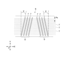
図1は、本開示の一実施の形態に係る磁気記録媒体10の断面構成例を表している。図1に示したように、磁気記録媒体10は複数層が積層された積層構造を有する。具体的には、磁気記録媒体10は、長尺のテープ状の基体11と、基体11の一方の主面11A上に設けられた下地層12と、下地層12の上に設けられた磁性層13と、基体11の他方の主面11B上に設けられたバック層14とを備える。磁性層13の表面13Sが、磁気ヘッドが当接しつつ走行することとなる表面となる。なお、下地層12およびバック層14は、必要に応じて備えられるものであり、無くてもよい。なお、磁気記録媒体10の平均厚みは、例えば5.6μm以下であるとよい。
<1. One embodiment>
[1-1 Configuration of magnetic recording medium 10]
FIG. 1 shows an example of a cross-sectional configuration of a
磁気記録媒体10は長尺のテープ状をなし、記録動作および再生動作の際には、自らの長手方向に沿って走行することとなる。磁気記録媒体10は、例えば記録用ヘッドとしてリング型ヘッドを備える記録再生装置に用いられるものであることが好ましい。
The
(基体11)
基体11は、下地層12および磁性層13を支持する非磁性支持体である。基体11は、長尺のフィルム状をなしている。基体11の平均厚みの上限値は、好ましくは4.2μm以下、より好ましくは4.0μm以下である。基体11の平均厚みの上限値が4.2μm以下であると、1データカートリッジ内に記録できる記録容量を一般的な磁気記録媒体よりも高めることができる。基体11の平均厚みの下限値は、好ましくは3μm以上、より好ましくは3.2μm以上である。基体11の平均厚みの下限値が3μm以上であると、基体11の強度低下を抑制することができる。
(Base 11)
The
基体11の平均厚みは以下のようにして求められる。まず、1/2インチ幅の磁気記録媒体10を準備し、それを250mmの長さに切り出し、サンプルを作製する。続いて、サンプルの基体11以外の層、すなわち下地層12、磁性層13およびバック層14をMEK(メチルエチルケトン)または希塩酸等の溶剤で除去する。次に、測定装置としてミツトヨ(Mitutoyo)社製レーザーホロゲージ(LGH-110C)を用いて、サンプルである基体11の厚みを5点以上の位置で測定する。その後、それらの測定値を単純に平均(算術平均)して、基体11の平均厚みを算出する。なお、測定位置は、サンプルから無作為に選ばれるものとする。
The average thickness of the
基体11は、例えば、ポリエステル類を主たる成分として含んでいる。基体11は、ポリエステル類に加えて、ポリオレフィン類、セルロース誘導体、ビニル系樹脂、およびその他の高分子樹脂のうちの少なくとも1種を含んでいてもよい。基体11が上記材料のうちの2種以上を含む場合、それらの2種以上の材料は混合されていてもよいし、共重合されていてもよいし、積層されていてもよい。
The
基体11に含まれるポリエステル類は、例えば、PET(ポリエチレンテレフタレート)、PEN(ポリエチレンナフタレート)、PBT(ポリブチレンテレフタレート)、PBN(ポリブチレンナフタレート)、PCT(ポリシクロヘキシレンジメチレンテレフタレート)、PEB(ポリエチレン-p-オキシベンゾエート)およびポリエチレンビスフェノキシカルボキシレートのうちの少なくとも1種を含む。 Examples of the polyesters contained in the base 11 include PET (polyethylene terephthalate), PEN (polyethylene naphthalate), PBT (polybutylene terephthalate), PBN (polybutylene naphthalate), PCT (polycyclohexylene dimethylene terephthalate), and PEB. (polyethylene-p-oxybenzoate) and polyethylene bisphenoxycarboxylate.
基体11に含まれるポリオレフィン類は、例えば、PE(ポリエチレン)およびPP(ポリプロピレン)のうちの少なくとも1種を含む。セルロース誘導体は、例えば、セルロースジアセテート、セルローストリアセテート、CAB(セルロースアセテートブチレート)およびCAP(セルロースアセテートプロピオネート)のうちの少なくとも1種を含む。ビニル系樹脂は、例えば、PVC(ポリ塩化ビニル)およびPVDC(ポリ塩化ビニリデン)のうちの少なくとも1種を含む。
The polyolefins contained in the
基体11に含まれるその他の高分子樹脂は、例えば、PA(ポリアミド、ナイロン)、芳香族PA(芳香族ポリアミド、アラミド)、PI(ポリイミド)、芳香族PI(芳香族ポリイミド)、PAI(ポリアミドイミド)、芳香族PAI(芳香族ポリアミドイミド)、PBO(ポリベンゾオキサゾール、例えばザイロン(登録商標))、ポリエーテル、PEK(ポリエーテルケトン)、ポリエーテルエステル、PES(ポリエーテルサルフォン)、PEI(ポリエーテルイミド)、PSF(ポリスルフォン)、PPS(ポリフェニレンスルフィド)、PC(ポリカーボネート)、PAR(ポリアリレート)およびPU(ポリウレタン)のうちの少なくとも1種を含む。 Other polymeric resins contained in the base 11 include, for example, PA (polyamide, nylon), aromatic PA (aromatic polyamide, aramid), PI (polyimide), aromatic PI (aromatic polyimide), and PAI (polyamideimide). ), aromatic PAI (aromatic polyamideimide), PBO (polybenzoxazole, e.g. Zylon (registered trademark)), polyether, PEK (polyetherketone), polyether ester, PES (polyether sulfone), PEI ( (polyetherimide), PSF (polysulfone), PPS (polyphenylene sulfide), PC (polycarbonate), PAR (polyarylate), and PU (polyurethane).
(磁性層13)
磁性層13は、信号を記録するための記録層である。磁性層13は、例えば、磁性粉、結着剤および潤滑剤を含む。磁性層13が、必要に応じて、導電性粒子、研磨剤、防錆剤等の添加剤をさらに含んでいてもよい。
(Magnetic layer 13)
The
磁性層13は、多数の孔部が設けられた表面13Sを有している。これらの多数の孔部には、潤滑剤が蓄えられている。多数の孔部は、磁性層13の表面に対して垂直方向に延設されていることが好ましい。磁性層13の表面13Sに対する潤滑剤の供給性を向上することができるからである。なお、多数の孔部の一部が垂直方向に延設されていてもよい。
The
磁性層13の表面13Sの算術平均粗さRaは、2.5nm以下、好ましくは2.2nm以下、より好ましくは1.9nm以下である。算術平均粗さRaが2.5nm以下であると、優れた電磁変換特性を得ることができる。磁性層13の表面13Sの算術平均粗さRaの下限値は、好ましくは1.0nm以上、より好ましくは1.2nm以上、さらにより好ましくは1.4nm以上である。磁性層13の表面13Sの算術平均粗さRaの下限値が1.0nm以上であると、摩擦の増大による走行性の低下を抑制することができる。
The arithmetic mean roughness Ra of the
表面13Sの算術平均粗さRaは以下のようにして求められる。まず、磁性層13の表面をAFM(Atomic Force Microscope)により観察し、40μm×40μmのAFM像を得る。AFMとしてはDigital Instruments社製、Nano Scope IIIa D3100を用い、カンチレバーとしてはシリコン単結晶製のものを用い、タッピング周波数として200Hz~400Hzのチューニングにて測定を行う。カンチレバーは、例えばNano World社製の「SPMプローブ NCH ノーマルタイプ PointProbe L(カンチレバー長)=125um」を用いることができる。次に、AFM像を512×512(=262,144)個の測定点に分割し、各測定点にて高さZ(i)(i:測定点番号、i=1~262,144)を測定し、測定した各測定点の高さZ(i)を単純に平均(算術平均)して平均高さ(平均面)Zave(=(Z(1)+Z(2)+・・・+Z(262,144))/262,144)を求める。続いて、各測定点での平均中心線からの偏差Z”(i)(=|Z(i)-Zave|)を求め、算術平均粗さRa[nm](=(Z”(1)+Z”(2)+・・・+Z”( 262,144))/262,144)を算出する。この際には、画像処理として、Flatten order2、ならびに、planefit order 3 XYによりフィルタリング処理を行ったものをデータとして用いる。
The arithmetic mean roughness Ra of the
また、磁性層13において、空間波長5μmまでのPSD (Power Spectrum Density)が例えば2.5um以下であることが望ましい。PSDを一定値以下に抑えることにより、記録再生を行う際の記録/再生ヘッドとテープ状の磁気記録媒体10とのスペーシングを小さくすることができ、高記録密度に適する磁気記録媒体10とすることができる。PSDの測定は以下のように行う。上記段落0022記載のフィルター処理後のデータに対して、解析モードPower Spectral Density(付属の解析ソフト)を実施する。解析するデータは、測定データ中、サンプルの長手方向(X)のみを選択および処理し、ASCファイル形式で保存後、エクセル(Excel)ファイルでデータを処理する。各周波数の振幅データについて、5μm以下の振幅データの総和を算出して、PDSとする。
Further, in the
潤滑剤を除去した状態における磁気記録媒体10の全体のBET比表面積の下限値は、2.5m2/g以上、好ましくは3.0m2/g以上、より好ましくは3.5m2/g以上、さらにより好ましくは4.0m2/g以上である。BET比表面積の下限値が2.5m2/g以上であると、繰り返し記録または再生を行った後にも(すなわち磁気ヘッドを磁気記録媒体10の表面に接触させて繰り返し走行を行った後にも)、磁性層13の表面と磁気ヘッドの間に対する潤滑剤の供給量の低下を抑制することができる。したがって、動摩擦係数の増加を抑制することができる。
The lower limit of the entire BET specific surface area of the
潤滑剤を除去した状態における磁気記録媒体10の全体のBET比表面積の上限値は、好ましくは7m2/g以下、より好ましくは6m2/g以下、さらにより好ましくは5.5m2/g以下である。BET比表面積の上限値が7m2/g以下であると、多数回走行後にも潤滑剤を枯渇することなく十分に供給できる。したがって、動摩擦係数の増加を抑制することができる。
The upper limit of the entire BET specific surface area of the
ここでいう潤滑剤を除去した状態における磁気記録媒体10とは、磁気記録媒体10を常温のヘキサンに24時間に亘って浸漬させたのち、ヘキサンから取り出して自然乾燥させた状態の磁気記録媒体10をいう。
The
BET比表面積は以下のようにして求められる。 The BET specific surface area is determined as follows.
まず、面積0.1265m2より1割程度大きいサイズの磁気記録媒体10をヘキサン中(磁気記録媒体10が十分に浸漬される量、例えば150mlのヘキサン中)に24時間浸したのち、自然乾燥させ、面積0.1265m2(例えば、乾燥後の磁気記録媒体10の両端50cm分を切り落とし、幅×10mの磁気記録媒体10を準備する。)のサイズに切り出すことにより、測定サンプルを作製する。次に、比表面積・細孔分布測定装置を用いて、BET比表面積を求める。以下に、測定装置および測定条件を示す。
測定環境:室温
測定装置:マイクロメトリクス(Micromeritics)社製3FLEX
測定吸着質:N2ガス
測定圧力範囲(P/P0):0~0.995
前記測定圧力範囲に関して、圧力を以下の表1の通りに変化させる。以下の表1における圧力値は相対圧P/P0である。以下の表において、例えばステップ1において、開始圧0.000から到達圧0.010へ、10秒当たり0.001変化するように、圧力が変化される。圧力が到達圧に達したら、次のステップにおける圧力変化が行われる。ステップ2~10においても同様である。ただし、各ステップにおいて、圧力が平衡に達していない場合は、装置は圧力が平衡になるのを待ってから次のステップに移行する。

Measurement environment: Room temperature Measuring device: 3FLEX manufactured by Micromeritics
Measured adsorbate: N2 gas measurement pressure range (P/P0): 0 to 0.995
Regarding the measurement pressure range, the pressure was changed as shown in Table 1 below. The pressure values in Table 1 below are relative pressures P/P0. In the table below, for example, in step 1, the pressure is changed from a starting pressure of 0.000 to an ultimate pressure of 0.010, changing by 0.001 per 10 seconds. Once the pressure reaches the ultimate pressure, the next step of pressure change is performed. The same applies to
磁性層13の平均厚みの上限値は、好ましくは90nm以下、特に好ましくは80nm以下、より好ましくは70nm以下、さらにより好ましくは60nm以下である。磁性層13の平均厚みの上限値が90nm以下であると、記録ヘッドとしてはリング型ヘッドを用いた場合に、磁性層13の厚み方向に均一に磁化を記録できるため、電磁変換特性を向上することができる。また、磁性層13の平均厚みの上限値が90nm以下であると、データ信号の再生波形における孤立波形の半値幅を狭くして(例えば200nm以下として)、データ信号の再生波形のピークを鋭くすることができる。これにより、データ信号の読み取り精度が向上するので、記録トラック数を増加させてデータの記録密度を向上させることができる。
The upper limit of the average thickness of the
磁性層13の平均厚みの下限値は、好ましくは35nm以上である。磁性層13の平均厚みの上限値が35nm以上であると、再生ヘッドとしてはMR型ヘッドを用いた場合に、出力を確保できるため、電磁変換特性を向上することができる。
The lower limit of the average thickness of the
磁性層13の平均厚みは以下のようにして求められる。まず、磁気記録媒体10の磁性層13の表面13Sおよびバック層14の表面14Sにカーボン膜を蒸着法により形成したのち、磁性層13の表面13Sを覆うカーボン膜の上にタングステン薄膜を蒸着法によりさらに形成する。これらのカーボン膜およびタングステン膜は、後述の薄片化処理においてサンプルを保護するものである。
The average thickness of the
次に、磁気記録媒体10をFIB(Focused Ion Beam)法等により加工して薄片化を行う。FIB法を使用する場合には、後述の断面のTEM像を観察する前処理として、保護膜としてカーボン膜及びタングステン薄膜を形成する。当該カーボン膜は蒸着法により磁気記録媒体10の磁性層側表面及びバック層側表面に形成され、そして、当該タングステン薄膜は蒸着法又はスパッタリング法により磁性層側表面にさらに形成される。当該薄片化は磁気記録媒体10の長さ方向(長手方向)に沿って行われる。すなわち、当該薄片化によって、磁気記録媒体10の長手方向及び厚み方向の両方に平行な断面が形成される。得られた薄片化サンプルの前記断面を、透過型電子顕微鏡(Transmission Electron Microscope:TEM)により、下記の条件で観察し、TEM像を得る。なお、装置の種類に応じて、倍率及び加速電圧は適宜調整されてよい。
装置:TEM(日立製作所製H9000NAR)
加速電圧:300kV
倍率:100,000倍
Next, the
Equipment: TEM (H9000NAR manufactured by Hitachi)
Acceleration voltage: 300kV
Magnification: 100,000x
次に、得られたTEM像を用い、磁気記録媒体10の長手方向の少なくとも10点以上の位置で磁性層13の厚みを測定する。得られた測定値を単純に平均(算術平均)した平均値を磁性層13の平均厚みとする。なお、前記測定が行われる位置は、試験片から無作為に選ばれるものとする。
Next, the thickness of the
(磁性粉)
磁性粉は、例えば、ε酸化鉄を含有するナノ粒子(以下「ε酸化鉄粒子」という。)の粉末を含んでいる。ε酸化鉄粒子は微粒子でも高保磁力を得ることができる。ε酸化鉄粒子に含まれるε酸化鉄は、磁気記録媒体10の厚み方向(垂直方向)に優先的に結晶配向していることが好ましい。
(Magnetic powder)
The magnetic powder includes, for example, powder of nanoparticles containing ε iron oxide (hereinafter referred to as "ε iron oxide particles"). Epsilon iron oxide particles can obtain high coercive force even in fine particles. The epsilon iron oxide contained in the epsilon iron oxide particles is preferably crystallized preferentially in the thickness direction (perpendicular direction) of the
図2は、磁性層13に含まれるε酸化鉄粒子20の断面構造の一例を模式的に表す断面図である。図2に示したように、ε酸化鉄粒子20は、球状もしくはほぼ球状を有しているか、または立方体状もしくはほぼ立方体状を有している。ε酸化鉄粒子20が上記のような形状を有しているので、磁性粒子としてε酸化鉄粒子20を用いた場合、磁性粒子として六角板状のバリウムフェライト粒子を用いた場合に比べて、磁気記録媒体10の厚み方向における粒子同士の接触面積を低減し、粒子同士の凝集を抑制することができる。したがって、磁性粉の分散性を高め、より良好なSNR(Signal-to-Noise Ratio)を得ることができる。
FIG. 2 is a cross-sectional view schematically showing an example of the cross-sectional structure of the ε
ε酸化鉄粒子20は、例えばコアシェル型構造を有する。具体的には、ε酸化鉄粒子20は、図2に示したように、コア部21と、このコア部21の周囲に設けられた2層構造のシェル部22とを備える。2層構造のシェル部22は、コア部21上に設けられた第1シェル部22aと、第1シェル部22a上に設けられた第2シェル部22bとを有する。
The ε
ε酸化鉄粒子20におけるコア部21は、ε酸化鉄を含んでいる。コア部21に含まれるε酸化鉄は、ε-Fe2O3結晶を主相とするものが好ましく、単相のε-Fe2O3からなるものがより好ましい。
The
第1シェル部22aは、コア部21の周囲のうちの少なくとも一部を覆っている。具体的には、第1シェル部22aは、コア部21の周囲を部分的に覆っていてもよいし、コア部21の周囲全体を覆っていてもよい。コア部21と第1シェル部22aの交換結合を十分なものとし、磁気特性を向上する観点からすると、コア部21の表面全体を覆っていることが好ましい。
The
第1シェル部22aは、いわゆる軟磁性層であり、例えば、α-Fe、Ni-Fe合金またはFe-Si-Al合金等の軟磁性体を含む。α-Feは、コア部21に含まれるε酸化鉄を還元することにより得られるものであってもよい。
The
第2シェル部22bは、酸化防止層としての酸化被膜である。第2シェル部22bは、α酸化鉄、酸化アルミニウムまたは酸化ケイ素を含む。α酸化鉄は、例えばFe3O4、Fe2O3およびFeOのうちの少なくとも1種の酸化鉄を含んでいる。第1シェル部22aがα-Fe(軟磁性体)を含む場合には、α酸化鉄は、第1シェル部22aに含まれるα-Feを酸化することにより得られるものであってもよい。
The
ε酸化鉄粒子20が、上述のように第1シェル部22aを有することで、熱安定性を確保するためにコア部21単体の保磁力Hcを大きな値に保ちつつ、ε酸化鉄粒子(コアシェル粒子)20全体としての保磁力Hcを記録に適した保磁力Hcに調整できる。また、ε酸化鉄粒子20が、上述のように第2シェル部22bを有することで、磁気記録媒体10の製造工程およびその工程前において、ε酸化鉄粒子20が空気中に暴露されて粒子表面に錆び等が発生することによりε酸化鉄粒子20の特性が低下するのを抑制することができる。したがって、第1シェル部22aを第2シェル部22bにより覆うことで、磁気記録媒体10の特性劣化を抑制することができる。
Since the ε
磁性粉の平均粒子サイズ(平均最大粒子サイズ)は、好ましくは25nm以下、より好ましくは8nm以上22nm以下、さらにより好ましくは12nm以上22nm以下である。磁気記録媒体10では、記録波長の1/2のサイズの領域が実際の磁化領域となる。このため、磁性粉の平均粒子サイズを最短記録波長の半分以下に設定することで、良好なS/Nを得ることができる。したがって、磁性粉の平均粒子サイズが22nm以下であると、高記録密度の磁気記録媒体10(例えば50nm以下の最短記録波長で信号を記録可能に構成された磁気記録媒体10)において、良好な電磁変換特性(例えばSNR)を得ることができる。一方、磁性粉の平均粒子サイズが8nm以上であると、磁性粉の分散性がより向上し、より優れた電磁変換特性(例えばSNR)を得ることができる。
The average particle size (average maximum particle size) of the magnetic powder is preferably 25 nm or less, more preferably 8 nm or more and 22 nm or less, and even more preferably 12 nm or more and 22 nm or less. In the
磁性粉の平均アスペクト比は、好ましくは1.0以上3.0以下、より好ましくは1.0以上2.8以下、さらにより好ましくは1.0以上2.0以下である。磁性粉の平均アスペクト比が1以上3.0以下の範囲内であると、磁性粉の凝集を抑制することができると共に、磁性層13の形成工程において磁性粉を垂直配向させる際に、磁性粉に加わる抵抗を抑制することができる。したがって、磁性粉の垂直配向性を向上することができる。
The average aspect ratio of the magnetic powder is preferably 1.0 or more and 3.0 or less, more preferably 1.0 or more and 2.8 or less, and even more preferably 1.0 or more and 2.0 or less. When the average aspect ratio of the magnetic powder is within the range of 1 or more and 3.0 or less, agglomeration of the magnetic powder can be suppressed, and when the magnetic powder is vertically aligned in the process of forming the
上記の磁性粉の平均粒子サイズおよび平均アスペクト比は、以下のようにして求められる。まず、測定対象となる磁気記録媒体10をFIB(Focused Ion Beam)法等により加工して薄片化を行う。薄片化は磁気テープの長さ方向(長手方向)に沿うかたちで行う。すなわち、この薄片化によって、磁気記録媒体10の長手方向および厚み方向の双方に平行な断面が形成される。得られた薄片サンプルについて、透過電子顕微鏡(日立ハイテクノ
ロジーズ製 H-9500)を用いて、加速電圧:200kV、総合倍率500,000倍で磁性層13の厚み方向に対して磁性層13全体が含まれるように断面観察を行い、TEM写真を撮影する。次に、撮影したTEM写真から50個の粒子を無作為に選び出し、各粒子の長軸長DLと短軸長DSとを測定する。ここで、長軸長DLとは、各粒子の輪郭に接するように、あらゆる角度から引いた2本の平行線間の距離のうち最大のもの(いわゆる最大フェレ径)を意味する。一方、短軸長DSとは、粒子の長軸長DLと直交する方向における粒子の長さのうち最大のものを意味する。
The average particle size and average aspect ratio of the above magnetic powder are determined as follows. First, the
続いて、測定した50個の粒子の長軸長DLを単純に平均(算術平均)して平均長軸長DLaveを求める。このようにして求めた平均長軸長DLaveを磁性粉の平均粒子サイズとする。また、測定した50個の粒子の短軸長DSを単純に平均(算術平均)して平均短軸長DSaveを求める。そして、平均長軸長DLaveおよび平均短軸長DSaveから粒子の平均アスペクト比(DLave/DSave)を求める。 Subsequently, the average long axis length DLave is determined by simply averaging (arithmetic mean) the long axis lengths DL of the 50 measured particles. The average major axis length DLave thus determined is defined as the average particle size of the magnetic powder. Further, the average short axis length DSave is obtained by simply averaging (arithmetic mean) the short axis lengths DS of the 50 measured particles. Then, the average aspect ratio (DLave/DSave) of the particles is determined from the average major axis length DLave and the average minor axis length DSave.
磁性粉の平均粒子体積は、好ましくは2300nm3以下、より好ましくは2200nm3以下、より好ましくは2100nm3以下、より好ましくは1950nm3以下、より好ましくは1600nm3以下、さらにより好ましくは1300nm3以下である。磁性粉の平均粒子体積が2300nm3以下であると、データ信号の再生波形における孤立波形の半値幅を狭くして(200nm以下)、データ信号の再生波形のピークを鋭くすることができる。これにより、データ信号の読み取り精度が向上するため、記録トラック数を増加させてデータの記録密度を向上させることができる(詳細は後述)。なお、磁性粉の平均粒子体積は、小さければ小さいほど良いので、体積の下限値については特に限定されないが、例えば、下限値は、1000nm3以上とされる。 The average particle volume of the magnetic powder is preferably 2300 nm 3 or less, more preferably 2200 nm 3 or less, more preferably 2100 nm 3 or less, more preferably 1950 nm 3 or less, more preferably 1600 nm 3 or less, even more preferably 1300 nm 3 or less. be. When the average particle volume of the magnetic powder is 2300 nm 3 or less, the half width of the isolated waveform in the reproduced data signal waveform can be narrowed (200 nm or less), and the peak of the reproduced data signal waveform can be sharpened. This improves the accuracy of reading data signals, so it is possible to increase the number of recording tracks and improve the data recording density (details will be described later). Note that the lower average particle volume of the magnetic powder is better as it is smaller, so the lower limit of the volume is not particularly limited, but the lower limit is, for example, 1000 nm 3 or more.
ε酸化鉄粒子20が球状またはほぼ球状を有している場合には、磁性粉の平均粒子体積は以下のようにして求められる。まず、上記の磁性粉の平均粒子サイズの算出方法と同様にして、平均長軸長DLaveを求める。次に、以下の式により、磁性粉の平均体積Vを求める。
V=(π/6)×(DLave)3
When the ε
V=(π/6)×(DLave) 3
(結着剤)
結着剤としては、ポリウレタン系樹脂、塩化ビニル系樹脂等に架橋反応を付与した構造の樹脂が好ましい。しかしながら結着剤はこれらに限定されるものではなく、磁気記録媒体10に対して要求される物性等に応じて、その他の樹脂を適宜配合してもよい。配合する樹脂としては、通常、塗布型の磁気記録媒体10において一般的に用いられる樹脂であれば、特に限定されない。
(binder)
As the binder, a resin having a structure obtained by imparting a crosslinking reaction to a polyurethane resin, a vinyl chloride resin, or the like is preferable. However, the binder is not limited to these, and other resins may be appropriately blended depending on the physical properties required for the
例えば、ポリ塩化ビニル、ポリ酢酸ビニル、塩化ビニル-酢酸ビニル共重合体、塩化ビニル-塩化ビニリデン共重合体、塩化ビニル-アクリロニトリル共重合体、アクリル酸エステル-アクリロニトリル共重合体、アクリル酸エステル-塩化ビニル-塩化ビニリデン共重合体、塩化ビニル-アクリロニトリル共重合体、アクリル酸エステル-アクリロニトリル共重合体、アクリル酸エステル-塩化ビニリデン共重合体、メタクリル酸エステル-塩化ビニリデン共重合体、メタクリル酸エステル-塩化ビニル共重合体、メタクリル酸エステル-エチレン共重合体、ポリ弗化ビニル、塩化ビニリデン-アクリロニトリル共重合体、アクリロニトリル-ブタジエン共重合体、ポリアミド樹脂、ポリビニルブチラール、セルロース誘導体(セルロースアセテートブチレート、セルロースダイアセテート、セルローストリアセテート、セルロースプロピオネート、ニトロセルロース)、スチレンブタジエン共重合体、ポリエステル樹脂、アミノ樹脂、合成ゴム等が挙げられる。 For example, polyvinyl chloride, polyvinyl acetate, vinyl chloride-vinyl acetate copolymer, vinyl chloride-vinylidene chloride copolymer, vinyl chloride-acrylonitrile copolymer, acrylic ester-acrylonitrile copolymer, acrylic ester-chlorinated Vinyl-vinylidene chloride copolymer, vinyl chloride-acrylonitrile copolymer, acrylic ester-acrylonitrile copolymer, acrylic ester-vinylidene chloride copolymer, methacrylic ester-vinylidene chloride copolymer, methacrylic ester-chloride Vinyl copolymers, methacrylic acid ester-ethylene copolymers, polyvinyl fluoride, vinylidene chloride-acrylonitrile copolymers, acrylonitrile-butadiene copolymers, polyamide resins, polyvinyl butyral, cellulose derivatives (cellulose acetate butyrate, cellulose dichloromethane) acetate, cellulose triacetate, cellulose propionate, nitrocellulose), styrene-butadiene copolymer, polyester resin, amino resin, synthetic rubber, and the like.
また、熱硬化性樹脂、または反応型樹脂の例としては、フェノール樹脂、エポキシ樹脂、尿素樹脂、メラミン樹脂、アルキッド樹脂、シリコーン樹脂、ポリアミン樹脂、尿素ホルムアルデヒド樹脂等が挙げられる。 Further, examples of thermosetting resins or reactive resins include phenol resins, epoxy resins, urea resins, melamine resins, alkyd resins, silicone resins, polyamine resins, urea formaldehyde resins, and the like.
また、上述した各結着剤には、磁性粉の分散性を向上させる目的で、-SO3M、-OSO3M、-COOM、P=O(OM)2等の極性官能基が導入されていてもよい。ここで、上記化学式中のMは、水素原子、またはリチウム、カリウム、ナトリウム等のアルカリ金属である。 In addition, polar functional groups such as -SO 3 M, -OSO 3 M, -COOM, and P=O(OM) 2 are introduced into each of the above-mentioned binders for the purpose of improving the dispersibility of the magnetic powder. You can leave it there. Here, M in the above chemical formula is a hydrogen atom or an alkali metal such as lithium, potassium, or sodium.
さらに、極性官能基としては、-NR1R2、-NR1R2R3+X-の末端基を有する側鎖型のもの、>NR1R2+X-の主鎖型のものが挙げられる。ここで、上記式中のR1、R2、R3は、水素原子、または炭化水素基であり、X-は弗素、塩素、臭素、ヨウ素
等のハロゲン元素イオン、または無機もしくは有機イオンである。また、極性官能基としては、-OH、-SH、-CN、エポキシ基等も挙げられる。
Further, examples of the polar functional group include side chain types having terminal groups of -NR1R2 and -NR1R2R3 + X - , and main chain types having >NR1R2 + X - . Here, R1, R2, and R3 in the above formula are hydrogen atoms or hydrocarbon groups, and X- is a halogen element ion such as fluorine, chlorine, bromine, or iodine, or an inorganic or organic ion. Further, examples of the polar functional group include -OH, -SH, -CN, and epoxy group.
(潤滑剤)
磁性層13に含まれる潤滑剤は、例えば脂肪酸および脂肪酸エステルを含有している。潤滑剤に含有される脂肪酸は、例えば下記の一般式<1>により示される化合物および一般式<2>により示される化合物のうちの少なくとも一方を含むことが好ましい。また、潤滑剤に含有される脂肪酸エステルは、下記の一般式<3>により示される化合物および一般式<4>により示される化合物のうちの少なくとも一方を含むことが好ましい。潤滑剤が、一般式<1>により示される化合物および一般式<3>により示される化合物の2種を含むことにより、一般式<2>により示される化合物および一般式<3>により示される化合物の2種を含むことにより、一般式<1>により示される化合物および一般式<4>により示される化合物の2種を含むことにより、一般式<2>により示される化合物および一般式<4>により示される化合物の2種を含むことにより、一般式<1>により示される化合物、一般式<2>により示される化合物および一般式<3>により示される化合物の3種を含むことにより、一般式<1>により示される化合物、一般式<2>により示される化合物および一般式<4>により示される化合物の3種を含むことにより、一般式<1>により示される化合物、一般式<3>により示される化合物および一般式<4>により示される化合物の3種を含むことにより、一般式<2>により示される化合物、一般式<3>により示される化合物および一般式<4>により示される化合物の3種を含むことにより、または、一般式<1>により示される化合物、一般式<2>により示される化合物、一般式<3>により示される化合物および一般式<4>により示される化合物の4種を含むことにより、磁気記録媒体10における繰り返しの記録又は再生による動摩擦係数の増加を抑制することができる。その結果、磁気記録媒体10の走行性をさらに向上させることができる。
CH3(CH2)kCOOH ・・・<1>
(但し、一般式<1>において、kは14以上22以下の範囲、より好ましくは14以上18以下の範囲から選ばれる整数である。)
CH3(CH2)nCH=CH(CH2)mCOOH ・・・<2>
(但し、一般式<2>において、nとmとの和は12以上20以下の範囲、より好ましくは14以上18以下の範囲から選ばれる整数である。)
CH3(CH2)pCOO(CH2)qCH3 ・・・<3>
(但し、一般式<3>において、pは14以上22以下、より好ましくは14以上18以下の範囲から選ばれる整数であり、且つ、qは2以上5以下の範囲、より好ましくは2以上4以下の範囲から選ばれる整数である。)
CH3(CH2)pCOO-(CH2)qCH(CH3)2…<4>
(但し、前記一般式<4>において、pは14以上22以下の範囲から選ばれる整数であ
り、qは1以上3以下の範囲から選ばれる整数である。)
(lubricant)
The lubricant contained in the
CH 3 (CH 2 ) k COOH ... <1>
(However, in the general formula <1>, k is an integer selected from the range of 14 to 22, more preferably 14 to 18.)
CH 3 (CH 2 ) n CH=CH (CH 2 ) m COOH ...<2>
(However, in the general formula <2>, the sum of n and m is an integer selected from the range of 12 to 20, more preferably 14 to 18.)
CH 3 (CH 2 ) p COO (CH 2 ) q CH 3 ...<3>
(However, in general formula <3>, p is an integer selected from the range of 14 to 22, more preferably 14 to 18, and q is in the range of 2 to 5, more preferably 2 to 4 (It is an integer selected from the following range.)
CH 3 (CH 2 ) p COO-(CH 2 ) q CH(CH 3 ) 2 …<4>
(However, in the general formula <4>, p is an integer selected from the range of 14 to 22, and q is an integer selected from the range of 1 to 3.)
(添加剤)
磁性層13は、非磁性補強粒子として、酸化アルミニウム(α、βまたはγアルミナ)、酸化クロム、酸化珪素、ダイヤモンド、ガーネット、エメリー、窒化ホウ素、チタンカーバイト、炭化珪素、炭化チタン、酸化チタン(ルチル型またはアナターゼ型の酸化チタン)等をさらに含んでいてもよい。
(Additive)
The
(下地層12)
下地層12は、非磁性粉および結着剤を含む非磁性層である。下地層12が、必要に応じて、潤滑剤、導電性粒子、硬化剤および防錆剤等のうちの少なくとも1種の添加剤をさらに含んでいてもよい。また、下地層12は、複数層が積層されてなる多層構造を有していてもよい。下地層12の平均厚みは、好ましくは0.4μm以上1.4μm以下、より好ましくは0.6μm以上1.2μm以下である。
(base layer 12)
なお、下地層12の平均厚みは、例えば次のように求められる。まず、1/2インチ幅の磁気記録媒体10を準備し、それを250mmの長さに切り出し、サンプルを作製する。続いて、サンプルの磁気記録媒体10について、下地層12および磁性層13を基体11から剥がす。次に、測定装置としてミツトヨ(Mitutoyo)社製レーザーホロゲージ(LGH-110C)を用い、基体11から剥がした下地層12と磁性層13との積層体の厚みを、5点以上の位置で測定する。そののち、それらの測定値を単純平均(算術平均)し、下地層12と磁性層13との積層体の平均厚みを算出する。なお、測定位置は、サンプルから無作為に選ばれるものとする。最後に、その積層体の平均厚みから、上述のようにTEMを用いて測定した磁性層13の平均厚みを差し引くことにより、下地層12の平均厚みを求める。
Note that the average thickness of the
下地層12は、多数の孔部を有していることが好ましい。これらの多数の孔部に潤滑剤が蓄えられることで、繰り返し記録または再生を行った後にも(すなわち磁気ヘッドを磁気記録媒体10の表面に接触させて繰り返し走行を行った後にも)、磁性層13の表面13Sと磁気ヘッドとの間に対する潤滑剤の供給量の低下をさらに抑制することができる。したがって、動摩擦係数の増加をさらに抑制することができる。
It is preferable that the
繰り返し記録または再生後における動摩擦係数の低下を抑制する観点からすると、下地層12の孔部と磁性層13の孔部とがつながっていることが好ましい。ここで、下地層12の孔部と磁性層13の孔部とがつながっているとは、下地層12の多数の孔部のうちの一部のものと、磁性層13の多数の孔部のうちの一部のものとがつながっている状態を含むものとする。
From the viewpoint of suppressing a decrease in the coefficient of dynamic friction after repeated recording or reproduction, it is preferable that the holes in the
磁性層13の表面13Sに対する潤滑剤の供給性を向上する観点からすると、多数の孔部は、磁性層13の表面13Sに対して垂直方向に延設されているものを含んでいることが好ましい。また、磁性層13の表面13Sに対する潤滑剤の供給性を向上する観点からすると、磁性層13の表面13Sに対して垂直方向に延設された下地層12の孔部と、磁性層13の表面13Sに対して垂直方向に延設された磁性層13の孔部とがつながっていることが好ましい。
From the viewpoint of improving the supply of lubricant to the
(下地層12の非磁性粉)
非磁性粉は、例えば無機粒子粉または有機粒子粉の少なくとも1種を含む。また、非磁性粉は、カーボンブラック等の炭素粉を含んでいてもよい。なお、1種の非磁性粉を単独で用いてもよいし、2種以上の非磁性粉を組み合わせて用いてもよい。無機粒子は、例えば、金属、金属酸化物、金属炭酸塩、金属硫酸塩、金属窒化物、金属炭化物または金属硫
化物等を含む。非磁性粉の形状としては、例えば、針状、球状、立方体状、板状等の各種形状が挙げられるが、これに限定されるものではない。
(Non-magnetic powder of base layer 12)
The non-magnetic powder includes, for example, at least one of inorganic particle powder and organic particle powder. Further, the non-magnetic powder may include carbon powder such as carbon black. Note that one type of non-magnetic powder may be used alone, or two or more types of non-magnetic powder may be used in combination. Inorganic particles include, for example, metals, metal oxides, metal carbonates, metal sulfates, metal nitrides, metal carbides, metal sulfides, and the like. Examples of the shape of the non-magnetic powder include various shapes such as acicular, spherical, cubic, and plate-like, but are not limited thereto.
(下地層12の結着剤)
下地層12における結着剤は、上述の磁性層13と同様である。
(Binder for base layer 12)
The binder in the
(バック層14)
バック層14は、例えば結着剤および非磁性粉を含んでいる。バック層14が、必要に応じて潤滑剤、硬化剤および帯電防止剤等のうちの少なくとも1種の添加剤をさらに含んでいてもよい。バック層14における結着剤および非磁性粉は、上述の下地層12における結着剤および非磁性粉と同様である。
(Back layer 14)
The
バック層14における非磁性粉の平均粒子サイズは、好ましくは10nm以上150nm以下、より好ましくは15nm以上110nm以下である。バック層14の非磁性粉の平均粒子サイズは、上記の磁性層13における磁性粉の平均粒子サイズと同様にして求められる。非磁性粉が、2以上の粒度分布を有するものを含んでいてもよい。
The average particle size of the nonmagnetic powder in the
バック層14の平均厚みの上限値は、好ましくは0.6μm以下であり、特に好ましくは0.5μm以下である。バック層14の平均厚みの上限値が0.6μm以下であると、磁気記録媒体10の平均厚みが5.6μm以下である場合でも、下地層12や基体11の厚みを厚く保つことができるので、磁気記録媒体10の記録再生装置内での走行安定性を保つことができる。バック層14の平均厚みの下限値は特に限定されるものではないが、例えば0.2μm以上であり、特に好ましくは0.3μm以上である。
The upper limit of the average thickness of the
バック層14の平均厚みは以下のようにして求められる。まず、1/2インチ幅の磁気記録媒体10を準備し、それを250mmの長さに切り出し、サンプルを作製する。次に、測定装置としてミツトヨ(Mitutoyo)社製レーザーホロゲージ(LGH-110C)を用いて、サンプルである磁気記録媒体10の厚みを5点以上で測定し、それらの測定値を単純に平均(算術平均)して、磁気記録媒体10の平均厚みtT[μm]を算出する。なお、測定位置は、サンプルから無作為に選ばれるものとする。続いて、サンプルの磁気記録媒体10からバック層14をMEK(メチルエチルケトン)または希塩酸等の溶剤で除去する。そののち、再び上記のレーザーホロゲージを用い、磁気記録媒体10からバック層14を除去したサンプルの厚みを5点以上で測定し、それらの測定値を単純に平均(算術平均)してバック層14を除去した磁気記録媒体10の平均厚みtB[μm]を算出する。なお、測定位置は、サンプルから無作為に選ばれるものとする。最後に、以下の式よりバック層14の平均厚みtb[μm]を求める。
tb[μm]=tT[μm]-tB[μm]
The average thickness of the
t b [μm] = t T [μm] - t B [μm]
バック層14は、多数の突部が設けられた表面を有している。多数の突部は、磁気記録媒体10をロール状に巻き取った状態において、磁性層13の表面に多数の孔部を形成するためのものである。多数の孔部は、例えば、バック層14の表面から突出された多数の非磁性粒子により構成されている。
The
ここでは、バック層14の表面に設けられた多数の突部を、磁性層13の表面に転写することにより磁性層13の表面に多数の孔部を形成する場合について説明したが、多数の孔部の形成方法はこれに限定されるものではない。例えば、磁性層形成用塗料に含まれる溶剤の種類および磁性層形成用塗料の乾燥条件等を調整することで、磁性層13の表面に多数の孔部を形成するようにしてもよい。
Here, a case has been described in which a large number of holes are formed on the surface of the
[磁気記録媒体の平均厚み]
磁気記録媒体10の平均厚み(平均全厚)の上限値は、好ましくは5.6μm以下、より好ましくは5.0μm以下、特に好ましくは4.6μm以下、さらにより好ましくは4.4μm以下である。磁気記録媒体10の平均厚みが5.6μm以下であると、1データカートリッジ内に記録できる記録容量を一般的な磁気記録媒体よりも高めることができる。磁気記録媒体10の平均厚みの下限値は特に限定されるものではないが、例えば3.5μm以上である。
[Average thickness of magnetic recording medium]
The upper limit of the average thickness (average total thickness) of the
磁気記録媒体10の平均厚みtTは以下のようにして求められる。まず、1/2インチ幅の磁気記録媒体10を準備し、それを250mmの長さに切り出し、サンプルを作製する。次に、測定装置としてMitutoyo社製レーザーホロゲージ(LGH-110C)を用いて、サンプルの厚みを5点以上の位置で測定し、それらの測定値を単純に平均(算術平均)して、平均値tT[μm]を算出する。なお、測定位置は、サンプルから無作為に選ばれるものとする。
The average thickness tT of the
(垂直方向における保磁力Hc1)
垂直方向における保磁力Hc1の上限値が、3000Oe以下、より好ましくは2900Oe以下、さらにより好ましくは2850Oe以下である。保磁力Hc1が大きいことは、熱擾乱および反磁界の影響を受けにくくなり好ましい。ただし、保磁力Hc1が3000Oeを超えると記録ヘッドでの飽和記録が困難となり、それによって記録できない部分が存在しノイズが増加し、結果として電磁変換特性(例えばC/N)が悪化してしまうおそれがある。
(Coercive force Hc1 in the vertical direction)
The upper limit of the coercive force Hc1 in the vertical direction is 3000 Oe or less, more preferably 2900 Oe or less, even more preferably 2850 Oe or less. It is preferable that the coercive force Hc1 is large because it is less susceptible to thermal disturbances and demagnetizing fields. However, if the coercive force Hc1 exceeds 3000 Oe, it becomes difficult for the recording head to perform saturation recording, and as a result, there are areas that cannot be recorded, noise increases, and as a result, there is a risk that electromagnetic conversion characteristics (for example, C/N) may deteriorate. There is.
垂直方向における保磁力Hc1の下限値が、好ましくは2200Oe以上、より好ましくは2400Oe以上、さらにより好ましくは2600Oe以上である。保磁力Hc1が2200Oe以上であると、熱擾乱の影響および反磁界の影響による、高温環境下における電磁変換特性(例えばC/N)の低下を抑制することができる。 The lower limit of the coercive force Hc1 in the vertical direction is preferably 2200 Oe or more, more preferably 2400 Oe or more, even more preferably 2600 Oe or more. When the coercive force Hc1 is 2200 Oe or more, it is possible to suppress deterioration of electromagnetic conversion characteristics (for example, C/N) in a high-temperature environment due to the influence of thermal disturbance and the influence of a demagnetizing field.
上記の保磁力Hc1は以下のようにして求められる。磁気記録媒体10を3枚重ね合わせて両面テープで接着したのち、φ6.39mmのパンチで打ち抜くことにより測定サンプルを作成する。この際に、磁気記録媒体の長手方向(走行方向)が認識できるように、磁性を持たない任意のインクでマーキングを行う。そして、振動試料型磁力計(Vibrating Sample Magnetometer:VSM)を用いて磁気記録媒体10の長手方向(磁気記録媒体10の走行方向)に対応する測定サンプル(磁気記録媒体10全体)のM-Hループを測定する。次に、アセトンまたはエタノール等を用いて塗膜(下地層12、磁性層13およびバック層14等)を払拭し、基体11のみを残す。そして、得られた基体11を両面テープで3枚重ね合わせて接着したのち、φ6.39mmのパンチで打ち抜くことによりバックグラウンド補正用のサンプル(以下、単に補正用サンプルという。)を得る。そののち、VSMを用いて基体11の垂直方向(磁気記録媒体10の厚み方向)に対応する補正用サンプル(基体11)のM-Hループを測定する。
The above coercive force Hc1 is determined as follows. A measurement sample is prepared by stacking three
測定サンプル(磁気記録媒体10全体)のM-Hループおよび補正用サンプル(基体11)のM-Hループの測定においては、例えば東英工業製の好感度振動試料型磁力計「VSM-P7-15型」が用いられる。測定条件は、測定モード:フルループ、最大磁界:15kOe、磁界ステップ:40bit、Time constant of Locking amp:0.3sec、Waiting time:1sec、MH平均数:20とする。 In the measurement of the MH loop of the measurement sample (the entire magnetic recording medium 10) and the MH loop of the correction sample (substrate 11), for example, a sensitive vibrating sample magnetometer manufactured by Toei Kogyo ``VSM-P7- 15 type" is used. The measurement conditions are: measurement mode: full loop, maximum magnetic field: 15 kOe, magnetic field step: 40 bits, time constant of locking amp: 0.3 sec, waiting time: 1 sec, and average number of MHs: 20.
2つのM-Hループを得たのち、測定サンプル(磁気記録媒体10全体)のM-Hループから補正用サンプル(基体11)のM-Hループが差し引かれることで、バックグラウンド補正が行われ、バックグラウンド補正後のM-Hループが得られる。このバックグラウンド補正の計算には、「VSMP7-15型」に付属されている測定・解析プログラムが用いられる。 After obtaining the two MH loops, background correction is performed by subtracting the MH loop of the correction sample (substrate 11) from the MH loop of the measurement sample (the entire magnetic recording medium 10). , the MH loop after background correction is obtained. The measurement and analysis program attached to the "VSMP7-15" is used to calculate this background correction.
得られたバックグラウンド補正後のM-Hループから保磁力Hc1が求められる。なお、この計算には、「VSM-P7-15型」に付属されている測定・解析プログラムが用いられる。なお、上記のM-Hループの測定はいずれも、25℃にて行われるものとする。また、M-Hループを磁気記録媒体10の垂直方向に測定する際の"反磁界補正"は行わないものとする。
The coercive force Hc1 is determined from the obtained MH loop after background correction. Note that this calculation uses the measurement and analysis program attached to the "VSM-P7-15 type". Note that all of the above MH loop measurements are performed at 25°C. Further, it is assumed that "demagnetizing field correction" is not performed when measuring the MH loop in the direction perpendicular to the
(長手方向における保磁力Hc2)
磁気記録媒体10の長手方向における保磁力Hc2の上限値は、好ましくは2000Oe以下、より好ましくは1900Oe以下、さらにより好ましくは1800Oe以下である。長手方向における保磁力Hc2が2000Oe以下であると、記録ヘッドからの垂直方向の磁界により感度良く磁化が反応するため、良好な記録パターンを形成することができる。
(Coercive force Hc2 in longitudinal direction)
The upper limit of the coercive force Hc2 in the longitudinal direction of the
磁気記録媒体10の長手方向に測定した保磁力Hc2の下限値は、好ましくは1000Oe以上である。長手方向にける保磁力Hcの下限値が1000Oe以上であると、記録ヘッドからの漏れ磁束による減磁を抑制することができる。
The lower limit of the coercive force Hc2 measured in the longitudinal direction of the
上記の保磁力Hc2は、測定サンプル全体およびバックグラウンド補正用のサンプルのM-Hループを磁気記録媒体10の長手方向(走行方向)に対応する方向に測定すること以外は、垂直方向における保磁力Hc1と同様にして求められる。
The above coercive force Hc2 is a coercive force in the vertical direction, except that the entire measurement sample and the MH loop of the sample for background correction are measured in the direction corresponding to the longitudinal direction (running direction) of the
(Hc2/Hc1)
垂直方向における保磁力Hc1と、長手方向における保磁力Hc2の比Hc2/Hc1が、Hc2/Hc1≦0.8、好ましくはHc2/Hc1≦0.75、より好ましくはHc2/Hc1≦0.7、さらにより好ましくはHc2/Hc1≦0.65、特に好ましくはHc2/Hc1≦0.6の関係を満たす。保磁力Hc1、Hc2がHc2/Hc1≦0.8の関係を満たすことで、磁性粉の垂直配向度を高めることができる。したがって、磁化遷移幅を低減し、かつ信号再生時に高出力の信号を得ることができるので、電磁変換特性(例えばC/N)を向上することができる。なお、上述したように、Hc2が小さいと、記録ヘッドからの垂直方向の磁界により感度良く磁化が反応するため、良好な記録パターンを形成することができる。
(Hc2/Hc1)
The ratio Hc2/Hc1 of the coercive force Hc1 in the vertical direction and the coercive force Hc2 in the longitudinal direction is Hc2/Hc1≦0.8, preferably Hc2/Hc1≦0.75, more preferably Hc2/Hc1≦0.7, Even more preferably, the relationship Hc2/Hc1≦0.65 is satisfied, particularly preferably Hc2/Hc1≦0.6. When the coercive forces Hc1 and Hc2 satisfy the relationship Hc2/Hc1≦0.8, the degree of vertical orientation of the magnetic powder can be increased. Therefore, it is possible to reduce the magnetization transition width and obtain a high-output signal during signal reproduction, so that electromagnetic conversion characteristics (for example, C/N) can be improved. Note that, as described above, when Hc2 is small, the magnetization reacts with high sensitivity to the perpendicular magnetic field from the recording head, so that a good recording pattern can be formed.
比Hc2/Hc1がHc2/Hc1≦0.8である場合、磁性層13の平均厚みが90nm以下であることが特に有効である。磁性層13の平均厚みが90nmを超えると、記録ヘッドとしてリング型ヘッドを用いた場合に、磁性層13の下部領域(下地層12側の領域)が長手方向に磁化されてしまい、磁性層13を厚み方向に均一に磁化することができなくなるおそれがある。したがって、比Hc2/Hc1をHc2/Hc1≦0.8としても(すなわち、磁性粉の垂直配向度を高めても)、電磁変換特性(例えばC/N)を向上することができなくなるおそれがある。
When the ratio Hc2/Hc1 is Hc2/Hc1≦0.8, it is particularly effective that the average thickness of the
Hc2/Hc1の下限値は特に限定されるものではないが、例えば0.5≦Hc2/Hc1である。 The lower limit value of Hc2/Hc1 is not particularly limited, but is, for example, 0.5≦Hc2/Hc1.
なお、Hc2/Hc1は磁性粉の垂直配向度を表しており、Hc2/Hc1が小さいほど磁性粉の垂直配向度が高くなる。以下に、本実施形態において、磁性粉の垂直配向度を示す指標としてHc2/Hc1を用いる理由について説明する。 Note that Hc2/Hc1 represents the degree of vertical orientation of the magnetic powder, and the smaller Hc2/Hc1, the higher the degree of vertical orientation of the magnetic powder. The reason why Hc2/Hc1 is used as an index indicating the degree of vertical orientation of magnetic powder in this embodiment will be explained below.
従来、一般的には磁性粉の垂直配向度を示す指標(パラメータ)としては、角形比SQ(=(Mr/Ms)×100、但し、Mr(emu):残留磁化、Ms(emu):飽和磁化)が用いられてきた。しかしながら、本発明者らの知見によれば、角形比SQという指標は、以下の理由により磁性粉の垂直配向度を示す指標としては適当でない。
(1)角形比SQは、磁性粉の保磁力Hcの値により変動してしまう。例えば、図5に示すように、磁性粉の保磁力Hcが大きくなると、見かけ上、角形比SQも大きい値となる。
(2)角形比SQは、過分散によるM-Hループの歪みの影響を受ける。
Conventionally, the index (parameter) that generally indicates the degree of vertical orientation of magnetic powder is the squareness ratio SQ (= (Mr/Ms) x 100, where Mr (emu): residual magnetization, Ms (emu): saturation. magnetization) has been used. However, according to the findings of the present inventors, the squareness ratio SQ is not suitable as an index indicating the degree of vertical orientation of magnetic powder for the following reasons.
(1) The squareness ratio SQ varies depending on the value of the coercive force Hc of the magnetic powder. For example, as shown in FIG. 5, when the coercive force Hc of the magnetic powder increases, the apparent squareness ratio SQ also becomes a large value.
(2) The squareness ratio SQ is affected by distortion of the MH loop due to overdispersion.
そこで、本実施形態においては、より適切に磁性粉の配向度を示す指標として、Hc2/Hc1を用いる。保磁力Hc1、Hc2は磁性粉の配向方向によって単純に変化するため、Hc2/Hc1が磁性粉の配向度を示す指標としてより適切である。 Therefore, in this embodiment, Hc2/Hc1 is used as an index that more appropriately indicates the degree of orientation of magnetic powder. Since the coercive forces Hc1 and Hc2 simply change depending on the orientation direction of the magnetic powder, Hc2/Hc1 is more suitable as an index indicating the degree of orientation of the magnetic powder.
(角形比)
磁気記録媒体10の垂直方向(厚み方向)における角形比S1は、例えば65%以上であり、好ましくは70%以上、より好ましくは75%以上、さらにより好ましくは80%以上、特に好ましくは85%以上である。角形比S1が65%以上であると、磁性粉の垂直配向性が十分に高くなるため、より優れたSNRを得ることができる。
(Square ratio)
The squareness ratio S1 in the vertical direction (thickness direction) of the
角形比S1は以下のようにして求められる。磁気記録媒体10を3枚重ね合わせて両面テープで接着したのち、φ6.39mmのパンチで打ち抜くことにより測定サンプルを作成する。この際に、磁気記録媒体の長手方向(走行方向)が認識できるように、磁性を持たない任意のインクでマーキングを行う。そして、振動試料型磁力計(Vibrating Sample Magnetometer:VSM)を用いて磁気記録媒体10の長手方向(磁気記録媒体10の走行方向)に対応する測定サンプル(磁気記録媒体10全体)のM-Hループを測定する。次に、アセトンまたはエタノール等を用いて塗膜(下地層12、磁性層13およびバック層14等)を払拭し、基体11のみを残す。そして、得られた基体11を両面テープで3枚重ね合わせて接着したのち、φ6.39mmのパンチで打ち抜くことによりバックグラウンド補正用のサンプル(以下、単に補正用サンプルという。)を得る。そののち、VSMを用いて基体11の長手方向(磁気記録媒体10の走行方向)に対応する補正用サンプル(基体11)のM-Hループを測定する。
The squareness ratio S1 is determined as follows. A measurement sample is prepared by stacking three
測定サンプル(磁気記録媒体10全体)のM-Hループおよび補正用サンプル(基体11)のM-Hループの測定においては、例えば東英工業製の好感度振動試料型磁力計「VSM-P7-15型」が用いられる。測定条件は、測定モード:フルループ、最大磁界:15kOe、磁界ステップ:40bit、Time constant of Locking amp:0.3sec、Waiting time:1sec、MH平均数:20とする。 In the measurement of the MH loop of the measurement sample (the entire magnetic recording medium 10) and the MH loop of the correction sample (substrate 11), for example, a sensitive vibrating sample magnetometer manufactured by Toei Kogyo ``VSM-P7- 15 type" is used. The measurement conditions are: measurement mode: full loop, maximum magnetic field: 15 kOe, magnetic field step: 40 bits, time constant of locking amp: 0.3 sec, waiting time: 1 sec, and average number of MHs: 20.
2つのM-Hループを得たのち、測定サンプル(磁気記録媒体10全体)のM-Hループから補正用サンプル(基体11)のM-Hループが差し引かれることで、バックグラウンド補正が行われ、バックグラウンド補正後のM-Hループが得られる。このバックグラウンド補正の計算には、「VSMP7-15型」に付属されている測定・解析プログラムが用いられる。 After obtaining the two MH loops, background correction is performed by subtracting the MH loop of the correction sample (substrate 11) from the MH loop of the measurement sample (the entire magnetic recording medium 10). , the MH loop after background correction is obtained. The measurement and analysis program attached to the "VSMP7-15" is used to calculate this background correction.
得られたバックグラウンド補正後のM-Hループの飽和磁化Ms(emu)および残留磁化Mr(emu)を以下の式に代入して、角形比S1(%)を計算する。
角形比S1(%)=(Mr/Ms)×100
なお、上記のM-Hループの測定はいずれも、25℃にて行われるものとする。また、M-Hループを磁気記録媒体10の垂直方向に測定する際の“反磁界補正”は行わないものとする。
The obtained saturation magnetization Ms (emu) and residual magnetization Mr (emu) of the MH loop after background correction are substituted into the following formula to calculate the squareness ratio S1 (%).
Squareness ratio S1 (%) = (Mr/Ms) x 100
Note that all of the above MH loop measurements are performed at 25°C. Further, it is assumed that "demagnetizing field correction" is not performed when measuring the MH loop in the direction perpendicular to the
磁気記録媒体10の長手方向(走行方向)における角形比S2は、好ましくは35%以下、より好ましくは30%以下、さらにより好ましくは25%以下、特に好ましくは20%以下、最も好ましくは15%以下である。角形比S2が35%以下であると、磁性粉の垂直配向性が十分に高くなるため、より優れたSNRを得ることができる。
The squareness ratio S2 in the longitudinal direction (running direction) of the
角形比S2は、M-Hループを磁気記録媒体10および基体11の長手方向(走行方向)に測定すること以外は角形比S1と同様にして求められる。
The squareness ratio S2 is determined in the same manner as the squareness ratio S1, except that the MH loop is measured in the longitudinal direction (running direction) of the
(SFD)
磁気記録媒体10のSFD(Switching Field Distribution)曲線において、メインピーク高さXと磁場ゼロ付近のサブピークの高さYとのピーク比X/Yは、好ましくは3.0以上であり、より好ましくは5.0以上、さらにより好ましくは7.0以上、特に好ましくは10.0以上、最も好ましくは20.0以上である(図3参照)。ピーク比X/Yが3.0以上であると、実際の記録に寄与するε酸化鉄粒子20の他にε酸化鉄特有の低保磁力成分(例えば軟磁性粒子や超常磁性粒子等)が磁性粉中に多く含まれることを抑制できる。したがって、記録ヘッドからの漏れ磁界により、隣接するトラックに記録された磁化信号が劣化することを抑制できるので、より優れたSNRを得ることができる。ピーク比X/Yの上限値は特に限定されるものではないが、例えば100以下である。
(SFD)
In the SFD (Switching Field Distribution) curve of the
上記のピーク比X/Yは、以下のようにして求められる。まず、上記の保磁力Hcの測定方法と同様にして、バックグラウンド補正後のM-Hループを得る。次に、得られたM-HループからSFDカーブを算出する。SFDカーブの算出には測定機に付属のプログラムを用いてもよいし、その他のプログラムを用いてもよい。算出したSFDカーブがY軸(dM/dH)を横切る点の絶対値を「Y」とし、M-Hループで言うところの保磁力Hc近傍に見られるメインピークの高さを「X」として、ピーク比X/Yを算出する。なお、M-Hループの測定は、上記の保磁力Hcの測定方法と同様に25℃にて行われるものとする。また、M-Hループを磁気記録媒体10の厚み方向(垂直方向)に測定する際の“反磁界補正”は行わないものとする。また、使用するVSMの感度に合わせて、測定するサンプルを複数枚重ねてM-Hループを測定してもよい。
The above peak ratio X/Y is determined as follows. First, an MH loop after background correction is obtained in the same manner as the method for measuring the coercive force Hc described above. Next, an SFD curve is calculated from the obtained MH loop. A program attached to the measuring device may be used to calculate the SFD curve, or another program may be used. Let "Y" be the absolute value of the point where the calculated SFD curve crosses the Y axis (dM/dH), and let "X" be the height of the main peak seen near the coercive force Hc in the MH loop. Calculate the peak ratio X/Y. Note that the measurement of the MH loop is carried out at 25° C. in the same manner as the method for measuring the coercive force Hc described above. Further, when measuring the MH loop in the thickness direction (perpendicular direction) of the
(活性化体積Vact)
活性化体積Vactが、好ましくは8000nm3以下、より好ましくは6000nm3以下、さらにより好ましくは5000nm3以下、特に好ましくは4000nm3以下、最も好ましくは3000nm3以下である。活性化体積Vactが8000nm3以下であると、磁性粉の分散状態が良好になるため、ビット反転領域を急峻にすることができ、記録ヘッドからの漏れ磁界により、隣接するトラックに記録された磁化信号が劣化することを抑制できる。したがって、より優れたSNRが得られる。
(activation volume Vact)
The activation volume Vact is preferably 8000 nm 3 or less, more preferably 6000 nm 3 or less, even more preferably 5000 nm 3 or less, particularly preferably 4000 nm 3 or less, most preferably 3000 nm 3 or less. When the activation volume Vact is 8000 nm 3 or less, the magnetic powder is well dispersed, so the bit reversal region can be made steep, and the leakage magnetic field from the recording head can reduce the magnetization recorded in adjacent tracks. Signal deterioration can be suppressed. Therefore, better SNR is obtained.
上記の活性化体積Vactは、Street&Woolleyにより導出された下記の式により求められる。
Vact(nm3)=kB×T×Χirr/(μ0×Ms×S)
(但し、kB:ボルツマン定数(1.38×10⁻²³J/K)、T:温度(K)、Χirr:非可逆磁化率、μ0:真空の透磁率、S:磁気粘性係数、Ms:飽和磁化(emu/cm3))
The above activation volume Vact is determined by the following formula derived by Street & Woolley.
Vact (nm 3 )=kB×T×Χirr/(μ0×Ms×S)
(However, kB: Boltzmann constant (1.38×10 -23 J/K), T: temperature (K), Χirr: irreversible magnetic susceptibility, μ0: magnetic permeability of vacuum, S: magnetorheological coefficient, Ms: saturation Magnetization (emu/cm 3 ))
上記式に代入される非可逆磁化率Χirr、飽和磁化Msおよび磁気粘性係数Sは、VSMを用いて以下のようにして求められる。VSMに用いる測定サンプルは、磁気記録媒体10を両面テープで3枚重ね合わされたものをφ6.39mmのパンチで打ち抜くことにより作製される。この際に、磁気記録媒体10の長手方向(走行方向)が認識できるように、磁性を持たない任意のインクでマーキングを行う。なお、VSMによる測定方向は、磁気記録媒体10の厚み方向(垂直方向)とする。また、VSMによる測定は、長尺状の磁気記録媒体10から切り出された測定サンプルに対して25℃にて行われるものとする。また、M-Hループを磁気記録媒体10の厚み方向(垂直方向)に測定する際の“反磁界補正”は行わないものとする。さらに、測定サンプル(磁気記録媒体10の全体)のM-Hループ、補正用サンプル(基体11)のM-Hループの測定においては、東英工業社製の高感度振動試料型磁力計「VSM-P7-15型」が用いられる。測定条件は、測定モード:フルループ、最大磁界:15kOe、磁界ステップ:40bit、Time constant of Locking amp:0.3sec、Waiting time:1sec、MH平均数:20とされる。
The irreversible magnetic susceptibility Χirr, the saturation magnetization Ms, and the magnetorheological coefficient S substituted into the above equation are obtained as follows using VSM. The measurement sample used for VSM is prepared by punching out three
(非可逆磁化率Χirr)
非可逆磁化率Χirrは、残留磁化曲線(DCD曲線)の傾きにおいて、残留保磁力Hr付近における傾きと定義される。まず、磁気記録媒体10全体に-1193kA/m(15kOe)の磁界を印加し、磁界をゼロに戻し残留磁化状態とする。その後、反対方向に約15.9kA/m(200Oe)の磁界を印加し再びゼロに戻し残留磁化量を測定する。その後も同様に、先ほどの印加磁界よりもさらに15.9kA/m大きい磁界を印加しゼロに戻す測定を繰り返し行い、印加磁界に対して残留磁化量をプロットしDCD曲線を測定する。得られたDCD曲線から、磁化量ゼロとなる点を残留保磁力Hrとし、さらにDCD曲線を微分し、各磁界におけるDCD曲線の傾きを求める。このDCD曲線の傾きにおいて、残留保磁力Hr付近の傾きがΧirrとなる。
(irreversible magnetic susceptibility Χirr)
The irreversible magnetic susceptibility Χirr is defined as the slope of the residual magnetization curve (DCD curve) near the residual magnetic force Hr. First, a magnetic field of -1193 kA/m (15 kOe) is applied to the entire
(飽和磁化Ms)
まず、上記の保磁力Hcの測定方法と同様にして、バックグラウンド補正後のM-Hループを得る。次に、得られたM-Hループの飽和磁化Ms(emu)の値と、測定サンプル中の磁性層13の体積(cm3)から、Ms(emu/cm3)を算出する。なお、磁性層13の体積は測定サンプルの面積に磁性層13の平均厚みを乗ずることにより求められる。磁性層13の体積の算出に必要な磁性層13の平均厚みの算出方法は、上述した通りである。
(Saturation magnetization Ms)
First, an MH loop after background correction is obtained in the same manner as the method for measuring the coercive force Hc described above. Next, Ms (emu/cm 3 ) is calculated from the value of the obtained saturation magnetization Ms (emu) of the MH loop and the volume (cm 3 ) of the
(磁気粘性係数S)
まず、磁気記録媒体10(測定サンプル)全体に-1193kA/m(15kOe)の磁界を印加し、磁界をゼロに戻し残留磁化状態とする。そののち、反対方向に、DCD曲線より得られた残留保磁力Hrの値と同等の磁界を印加する。磁界を印加した状態で1000秒間、磁化量を一定の時間間隔で継続的に測定する。このようにして得られた、時間tと磁化量M(t)との関係を以下の式に照らし合わせて磁気粘性係数Sを算出する。
M(t)=M0+S×ln(t)
(但し、M(t):時間tの磁化量、M0:初期の磁化量、S:磁気粘性係数、ln(t):時間の自然対数)
(Magneto-rheological coefficient S)
First, a magnetic field of -1193 kA/m (15 kOe) is applied to the entire magnetic recording medium 10 (measurement sample) to return the magnetic field to zero and create a residual magnetization state. Thereafter, a magnetic field equivalent to the value of the residual magnetic force Hr obtained from the DCD curve is applied in the opposite direction. The amount of magnetization is continuously measured at regular time intervals for 1000 seconds while a magnetic field is applied. The magnetorheological coefficient S is calculated by comparing the thus obtained relationship between the time t and the amount of magnetization M(t) with the following formula.
M(t)=M0+S×ln(t)
(However, M(t): amount of magnetization at time t, M0: amount of initial magnetization, S: magnetorheological coefficient, ln(t): natural logarithm of time)
(データバンドおよびサーボバンド)
図4は、磁気記録媒体10を上方から見た模式図である。図4に示したように、磁性層13は、磁気記録媒体10の長手方向(X軸方向)に延在する複数のデータバンドDB(図4ではデータバンドDB0~DB3を示す)と、磁気記録媒体10の長手方向(X軸方向)に延在する延在する複数のサーボバンドSB(図4ではサーボバンドSB0~SB4を示す)とを有している。複数のデータバンドDBには、それぞれデータ信号が書き込まれるようになっており、複数のサーボバンドSBには、磁気ヘッドのトラッキング制御をするためのサーボ信号がそれぞれ書き込まれるようになっている。また、各データバンドDBは、幅方向(Y軸方向)において隣り合う複数のサーボバンドSBによって挟み込まれるように配置されている。
(data band and servo band)
FIG. 4 is a schematic diagram of the
磁性層13の表面13Sの面積Sに対するサーボバンドSの総面積SSBの割合RS(=(SSB/S)×100)の上限値は、高記録容量を確保する観点から、好ましくは4.0%以下、より好ましくは3.0%以下、さらにより好ましくは2.0%以下である。一方、磁性層13の表面の面積Sに対するサーボバンドSBの総面積SSBの割合RSの下限値は、5以上のサーボトラックを確保する観点から、好ましくは0.8%以上である。
The upper limit of the ratio R S (=(S SB /S)×100) of the total area S SB of the servo band S to the area S of the
磁性層13の表面13Sの面積Sに対するサーボバンドSBの総面積SSBの割合RSは、例えば、磁気記録媒体10を、フェリコロイド現像液(株式会社シグマハイケミカル製、シグマ―カーQ)を用いて現像し、その後、現像した磁気記録媒体10を光学顕微鏡で観察することで測定することができる。光学顕微鏡の観察像から、サーボバンド幅WSBおよびサーボバンドSBの本数を測定する。次に、以下の式から割合RSを求める。
割合RS[%]=(((サーボバンド幅WSB)×(サーボバンド本数))/(磁気記録媒
体10の幅))×100
The ratio R S of the total area S SB of the servo band SB to the area S of the
Ratio R S [%] = (((servo band width W SB )×(number of servo bands))/(width of magnetic recording medium 10))×100
サーボバンドSBの数は、好ましくは5以上、より好ましくは5+4n(但し、nは正の整数である。)以上である。サーボバンドSBの数が5以上であると、磁気記録媒体10の幅方向の寸法変化によるサーボ信号への影響を抑制し、オフトラックが少ない安定した記録再生特性を確保できる。
The number of servo bands SB is preferably 5 or more, more preferably 5+4n (where n is a positive integer) or more. When the number of servo bands SB is 5 or more, it is possible to suppress the influence on servo signals due to dimensional changes in the width direction of the
サーボバンド幅WSBの上限値は、高記録容量を確保する観点から、好ましくは95μm以下、より好ましくは60μm以下、さらにより好ましくは30μm以下である。サーボバンド幅WSBの下限値は、記録ヘッド製造の観点から、好ましくは10μm以上である。サーボバンド幅WSBの幅は以下のようにして求められる。まず、磁気記録媒体10を、フェリコロイド現像液(株式会社シグマハイケミカル製、シグマ―カーQ)を用いて現像する。次に、現像した磁気記録媒体10を光学顕微鏡で観察することでサーボバンド幅WSBの幅を測定することができる。
The upper limit value of the servo bandwidth W SB is preferably 95 μm or less, more preferably 60 μm or less, and even more preferably 30 μm or less, from the viewpoint of ensuring high recording capacity. The lower limit of the servo band width W SB is preferably 10 μm or more from the viewpoint of manufacturing the recording head. The width of the servo band width WSB is determined as follows. First, the
図4に示したように、データバンドDBは、X軸方向に沿ってそれぞれ延在すると共にY軸方向において隣り合うように整列された複数の記録トラック5を形成可能である。データ信号は、この記録トラック5に沿って、記録トラック5内に記録される。なお、本技術において、データバンドDBに記録されるデータ信号における長手方向の1ビット長(磁化反転間距離)は、典型的には48nm以下とされる。サーボバンドSBは、サーボ信号記録装置(不図示)によってサーボ信号が記録された所定パターンのサーボ信号記録パターン6を含んでいる。
As shown in FIG. 4, the data band DB can form a plurality of
図5は、データバンドDBにおける記録トラック5を示す拡大図である。図5に示したように、各記録トラック5は、Y軸方向において所定の記録トラック幅Wdを有している。記録トラック幅Wdは、典型的には、3.0μm以下とされる。なお、このような記録トラック幅Wdは、例えば、磁気記録媒体10を、フェリコロイド現像液等の現像液を用いて現像したのち、現像した磁気記録媒体10を光学顕微鏡で観察することで測定することができる。
FIG. 5 is an enlarged view showing the
1本のデータバンドDBに含まれる記録トラック5の本数は、例えば、1000本から2000本程度とされる。
The number of
図6は、サーボバンドSBにおけるサーボ信号記録パターン6を示す拡大図である。図6に示すように、サーボ信号記録パターン6は、幅方向(Y軸方向)に対して所定のアジマス角αを持って傾斜する複数のストライプ7を含む。この複数のストライプ7は、幅方向(Y軸方向)に対して時計回りに傾斜する第1のストライプ群8と、幅方向に対して反時計回りに傾斜する第2のストライプ群9とに分類される。なお、このようなストライプ7の形状などは、例えば、磁気記録媒体10を、フェリコロイド現像液等の現像液を用いて現像し、その後、現像した磁気記録媒体10を光学顕微鏡で観察することで測定することができる。
FIG. 6 is an enlarged view showing the servo
図6には、サーボ信号記録パターン6上をサーボリードヘッドによってトレースされるラインであるサーボトレースラインTが破線により示されている。サーボトレースラインTは、長手方向(X軸方向)に沿って設定され、また、幅方向に所定の間隔Psを開けて設定される。
In FIG. 6, a servo trace line T, which is a line traced by a servo read head on the servo
1本のサーボバンドSBあたりのサーボトレースラインTの本数は、例えば、30本から60本程度とされる。 The number of servo trace lines T per one servo band SB is, for example, about 30 to 60.
隣接する2つのサーボトレースラインTの間隔Psは、記録トラック幅Wdの値と同じであり、例えば、2.0μm以下とされる。ここで、隣接する2つのサーボトレースラインTの間隔Psは、記録トラック幅Wdを決定付ける値とされている。つまり、サーボトレースラインTの間隔Psが狭められると、記録トラック幅Wdが小さくなり、1本のデータバンドDBに含まれる記録トラック5の本数が増える。結果として、データの記録容量が増えることになる(間隔Psが広くなる場合は、その逆)。したがって、記録容量の増加を図るには記録トラック幅Wdを小さくする必要があるが、サーボトレースラインTの間隔Psも狭められることになる結果、隣接するサーボトレースラインを正確にトレースすることが困難になる。そこで本実施形態では、後述するように、再生信号幅すなわちデータ信号の再生波形における孤立波形の半値幅を狭くすることで、記録トラック幅Wdの狭小化にも対応可能としている。
The distance Ps between two adjacent servo trace lines T is the same as the recording track width Wd, and is, for example, 2.0 μm or less. Here, the interval Ps between two adjacent servo trace lines T is a value that determines the recording track width Wd. That is, when the interval Ps between the servo trace lines T is narrowed, the recording track width Wd becomes smaller, and the number of
(摩擦係数比(μB/μA))
磁気記録媒体10の長手方向に0.4Nの張力を加えた状態における磁気記録媒体10の磁性層13の表面13Sと磁気ヘッドとの間の動摩擦係数μAと、磁気記録媒体10の長手方向に1.2Nの張力を加えた状態における磁気記録媒体10の磁性層13の表面13Sと磁気ヘッドとの間の動摩擦係数μBとの摩擦係数比(μB/μA)は、好ましくは1.0以上で2.1以下、より好ましくは1.2以上で1.8以下である。摩擦係数比(μB/μA)が1.0以上で2.1以下であると、走行時の張力変動による動摩擦係数の変化を小さくできるため、磁気記録媒体10の走行を安定させることができる。
(Friction coefficient ratio (μ B /μ A ))
The coefficient of dynamic friction μA between the
摩擦係数比(μB/μA)を算出するための動摩擦係数μAおよび動摩擦係数μBは以下のとおりにして求められる。まず、図7に示したように、1/2インチ幅の磁気記録媒体10を、互いに離間して平行に配置された1インチ径の円柱状の2本のガイドロール91,92に磁性層13の表面13Sが接触するように載せる。2本のガイドロール91,92は、互いの位置関係が固定されている。
The dynamic friction coefficient μA and the dynamic friction coefficient μB for calculating the friction coefficient ratio (μB/μA) are obtained as follows. First, as shown in FIG. 7, a 1/2 inch wide
次いで、LTO5ドライブに搭載されているヘッドブロック(記録再生用)93に対し、磁気記録媒体10を、磁性層13の表面13Sが接触し、かつ抱き角θ1[°]=5.6°となるように接触させ、磁気記録媒体10の一端を掴み治具94により把持して可動式ストレインゲージ95と繋ぐと共に、磁気記録媒体10の他端に錘96を吊り下げ、0.4NのテンションT0を付与する。なお、ヘッドブロック74は、抱き角θ1[°]が5.6°となった位置において固定されるようになっている。これにより、ガイドロール91,92とヘッドブロック93との位置関係も固定される。
Next, the
次いで、可動式ストレインゲージ95によって、磁気記録媒体10を、ヘッドブロック93に対して10mm/sの速度で可動式ストレインゲージ95へ向かうように60mm摺動させる。この摺動時の可動式ストレインゲージ95の出力値(電圧)を、事前に取得されている出力値と荷重との直線関係(後述する)に基づき、T[N]に変換する。上記60mmの摺動の摺動開始から摺動停止までの間に、13回T[N]を取得し、最初と最後の計2回を除いた11個のT[N]を単純平均することによって、Tave[N]が得られる。
その後、以下の式より動摩擦係数μAを求める。

Then, calculate the dynamic friction coefficient μA using the following formula.
上述の直線関係は以下のとおりに得られる。すなわち、可動式ストレインゲージ95に0.4Nの荷重をかけた場合と1.5Nの荷重をかけた場合のそれぞれについて、可動式ストレインゲージ95の出力値(電圧)を得る。得られた2つの出力値と前記2つの荷重とから、出力値と荷重との直線関係が得られる。当該直線関係を用いて、上記のとおり、摺動時の可動式ストレインゲージ95による出力値(電圧)がT[N]に変換される。
The above linear relationship is obtained as follows. That is, the output value (voltage) of the
動摩擦係数μBは、磁気記録媒体10の他端に付与されるテンションT0を1.2Nとすること以外は動摩擦係数μAの測定方法と同じ方法で測定される。
The dynamic friction coefficient μB is measured in the same manner as the dynamic friction coefficient μA, except that the tension T0 applied to the other end of the
以上のように測定された動摩擦係数μAおよび動摩擦係数μBから、摩擦係数比(μB/μA)が算出される。 A friction coefficient ratio (μB/μA) is calculated from the dynamic friction coefficient μA and the dynamic friction coefficient μB measured as described above.
磁気記録媒体10に加わる張力が0.6Nであるときの磁性層13の表面13Sと磁気ヘッドの間の動摩擦係数をμCとした場合、走行開始から5回目の動摩擦係数μC(5)と走行開始から1000回目の動摩擦係数μC(1000)との摩擦係数比(μC(1000)/μC(5))が、好ましくは1.0以上1.8以下、より好ましくは1.0以上1.6以下である。摩擦係数比(μC(1000)/μC(5))が1.0以上で1.8以下であると、多数回走行による動摩擦係数の変化を小さくできるため、磁気記録媒体10の走行を安定させることができる。ここで、磁気ヘッドとしては磁気記録媒体10に対応したドライブのものを用いるものとする。
If the kinetic friction coefficient between the
(摩擦係数比(μC(1000)/μC(5)))
摩擦係数比(μC(1000)/μC(5))を算出するための動摩擦係数μC(5)および動摩擦係数μC(1000)は以下のとおりにして求められる。
(Friction coefficient ratio (μ C(1000) / μ C(5) ))
The dynamic friction coefficient μC(5) and the dynamic friction coefficient μC(1000) for calculating the friction coefficient ratio (μC(1000)/μC(5)) are obtained as follows.
磁気記録媒体10は、好ましくは、長手方向に0.6Nの張力を加えた状態にある前記磁気記録媒体を、磁気ヘッド上を5往復摺動させた場合の5往復目における動摩擦係数μC(5)と、当該磁気ヘッド上を1000往復させた場合の1000往復目における動摩擦係数μC(1000)との摩擦係数比(μC(1000)/μC(5))が1.0~2.0であり、より好ましくは1.0~1.8であり、さらにより好ましくは1.0~1.6である。摩擦係数比(μC(1000)/μC(5))が上記数値範囲内にあることによって、多数回走行による動摩擦係数の変化を小さくすることができるため、磁気記録媒体10の走行を安定させることができる。
Preferably, the
摩擦係数比(μC(1000)/μC(5))を算出するための動摩擦係数μC(5)及び動摩擦係数μC(1000)は以下のとおりにして求められる。
磁気記録媒体10の前記他端に付与されるテンションT0[N]を0.6Nとすること以外は動摩擦係数μAの測定方法と同じようにして、磁気記録媒体10を可動式ストレインゲージ71と繋ぐ。そして、磁気記録媒体10を、ヘッドブロック74に対して10mm/sにて可動式ストレインゲージへ向かって60mm摺動させ(往路)及び可動式ストレインゲージから離れるように60mm摺動させる(復路)。この往復動作を1000回繰り返す。この1000回の往復動作のうち、5回目の往路の60mmの摺動の摺動開始から摺動停止までの間に、ストレインゲージの出力値(電圧)を13回を取得し、動摩擦係数μAで求めた出力値と荷重との直線関係(後述する)に基づき、T[N]に変換する。最初と最後の計2回を除いた11個を単純平均することによりTave[N]を求める。
以下の式により、動摩擦係数μC(5)を求める。

以上のとおりにして測定された動摩擦係数μC(5)及び動摩擦係数μC(1000)から、摩擦係数比μC(1000)/μC(5)が算出される。
The dynamic friction coefficient μ C( 5) and the dynamic friction coefficient μ C (1000) for calculating the friction coefficient ratio (μ C(1000) /μ C(5) ) are obtained as follows.
The
The dynamic friction coefficient μ C(5) is determined by the following formula.
The friction coefficient ratio μ C ( 1000 ) / μ C (5 ) is calculated from the dynamic friction coefficient μ C (5) and the dynamic friction coefficient μ C (1000 ) measured as described above.
[1-2 磁気記録媒体10の製造方法]
次に、上述の構成を有する磁気記録媒体10の製造方法について説明する。まず、非磁性粉、結着剤および潤滑剤等を溶剤に混練、分散させることにより、下地層形成用塗料を調製する。次に、磁性粉、結着剤および潤滑剤等を溶剤に混練、分散させることにより、磁性層形成用塗料を調製する。次に、結着剤および非磁性粉等を溶剤に混練、分散させることにより、バック層形成用塗料を調製する。磁性層形成用塗料、下地層形成用塗料およびバック層形成用塗料の調製には、例えば、以下の溶剤、分散装置および混練装置を用いることができる。
[1-2 Method for manufacturing magnetic recording medium 10]
Next, a method for manufacturing the
上述の塗料調製に用いられる溶剤としては、例えば、アセトン、メチルエチルケトン、メチルイソブチルケトン、シクロヘキサノン等のケトン系溶媒、メタノール、エタノール、プロパノール等のアルコール系溶媒、酢酸メチル、酢酸エチル、酢酸ブチル、酢酸プロピル、乳酸エチル、エチレングリコールアセテート等のエステル系溶媒、ジエチレングリコールジメチルエーテル、2-エトキシエタノール、テトラヒドロフラン、ジオキサン等のエーテル系溶媒、ベンゼン、トルエン、キシレン等の芳香族炭化水素系溶媒、メチレンクロライド、エチレンクロライド、四塩化炭素、クロロホルム、クロロベンゼン等のハロゲン化炭化水素系溶媒等が挙げられる。これらは単独で用いてもよく、適宜混合して用いてもよい。 Examples of solvents used in the above paint preparation include ketone solvents such as acetone, methyl ethyl ketone, methyl isobutyl ketone, and cyclohexanone, alcohol solvents such as methanol, ethanol, and propanol, methyl acetate, ethyl acetate, butyl acetate, and propyl acetate. , ester solvents such as ethyl lactate and ethylene glycol acetate, ether solvents such as diethylene glycol dimethyl ether, 2-ethoxyethanol, tetrahydrofuran, and dioxane, aromatic hydrocarbon solvents such as benzene, toluene, and xylene, methylene chloride, ethylene chloride, Examples include halogenated hydrocarbon solvents such as carbon tetrachloride, chloroform, and chlorobenzene. These may be used alone or in an appropriate mixture.
上述の塗料調製に用いられる混練装置としては、例えば、連続二軸混練機、多段階で希釈可能な連続二軸混練機、ニーダー、加圧ニーダー、ロールニーダー等の混練装置を用いることができるが、特にこれらの装置に限定されるものではない。また、上述の塗料調製に用いられる分散装置としては、例えば、ロールミル、ボールミル、横型サンドミル、縦型サンドミル、スパイクミル、ピンミル、タワーミル、パールミル(例えばアイリッヒ社製「DCPミル」等)、ホモジナイザー、超音波分散機等の分散装置を用いることができるが、特にこれらの装置に限定されるものではない。 As the kneading device used for preparing the above-mentioned paint, for example, a continuous twin-screw kneader, a continuous twin-screw kneader capable of diluting in multiple stages, a kneader, a pressure kneader, a roll kneader, etc. can be used. , but is not particularly limited to these devices. In addition, examples of dispersion equipment used in the above-mentioned paint preparation include roll mills, ball mills, horizontal sand mills, vertical sand mills, spike mills, pin mills, tower mills, pearl mills (for example, "DCP Mill" manufactured by Eirich, etc.), homogenizers, super Although a dispersion device such as a sonic dispersion machine can be used, the present invention is not particularly limited to these devices.
次に、下地層形成用塗料を基体11の一方の主面11Aに塗布して乾燥させることにより、下地層12を形成する。続いて、この下地層12上に磁性層形成用塗料を塗布して乾燥させることにより、磁性層13を下地層12上に形成する。なお、乾燥の際に、例えばソレノイドコイルにより、磁性粉を基体11の厚み方向に磁場配向させることが好ましい。また、乾燥の際に、例えばソレノイドコイルにより、磁性粉を基体11の走行方向(長手方向)に磁場配向させたのちに、基体11の厚み方向に磁場配向させるようにしてもよい。このような磁場配向処理をすることで、磁性粉の垂直配向度(すなわち角形比S1)を向上することができる。磁性層13の形成後、バック層形成用塗料を基体11の他方の主面11Bに塗布して乾燥させることにより、バック層14を形成する。これにより、磁気記録媒体10が得られる。
Next, the
角形比S1、S2や比Hc2/Hc1は、例えば、磁性層形成用塗料の塗膜に印加される磁場の強度、磁性層形成用塗料中における固形分の濃度、磁性層形成用塗料の塗膜の乾燥条件(乾燥温度および乾燥時間)を調整することにより所望の値に設定される。塗膜に印加される磁場の強度は、磁性粉の保磁力の2倍以上であることが好ましい。角形比S1をさらに高めるためには(すなわち角形比S2をさらに低めるためには)、磁性層形成用塗料中における磁性粉の分散状態を向上させることが好ましい。また、角形比S1をさらに高めるためには、磁性粉を磁場配向させるための配向装置に磁性層形成用塗料が入る前の段階で、磁性粉を磁化させておくことも有効である。なお、上記の角形比S1、S2の調整方法は単独で使用されてもよいし、2以上組み合わされて使用されてもよい。 The squareness ratios S1, S2 and the ratio Hc2/Hc1 are determined by, for example, the intensity of the magnetic field applied to the coating film of the magnetic layer forming paint, the concentration of solid content in the magnetic layer forming paint, and the coating film of the magnetic layer forming paint. The desired value is set by adjusting the drying conditions (drying temperature and drying time). The strength of the magnetic field applied to the coating film is preferably at least twice the coercive force of the magnetic powder. In order to further increase the squareness ratio S1 (that is, to further lower the squareness ratio S2), it is preferable to improve the state of dispersion of the magnetic powder in the coating material for forming the magnetic layer. In order to further increase the squareness ratio S1, it is also effective to magnetize the magnetic powder before the magnetic layer forming paint enters the orientation device for orienting the magnetic powder in a magnetic field. Note that the above methods for adjusting the squareness ratios S1 and S2 may be used alone or in combination of two or more.
その後、得られた磁気記録媒体10にカレンダー処理を行い、磁性層13の表面13Sを平滑化する。次に、カレンダー処理が施された磁気記録媒体10をロール状に巻き取ったのち、この状態で磁気記録媒体10に加熱処理を行うことにより、バック層14の表面14Sの多数の突部を磁性層13の表面13Sに転写する。これにより、磁性層13の表面13Sに多数の孔部が形成される。
Thereafter, the obtained
加熱処理の温度は、50℃以上80℃以下であることが好ましい。加熱処理の温度が50℃以上であると、良好な転写性を得ることができる。一方、加熱処理の温度が80℃以下であると、細孔量が多くなりすぎ、磁性層13の表面13Sの潤滑剤が過多になってしまうおそれがある。ここで、加熱処理の温度は、磁気記録媒体10を保持する雰囲気の温度である。
The temperature of the heat treatment is preferably 50°C or higher and 80°C or lower. When the temperature of the heat treatment is 50° C. or higher, good transferability can be obtained. On the other hand, if the temperature of the heat treatment is 80° C. or lower, the number of pores becomes too large, and there is a risk that there will be too much lubricant on the
加熱処理の時間は、15時間以上40時間以下であることが好ましい。加熱処理の時間が15時間以上であると、良好な転写性を得ることができる。一方、加熱処理の時間が40時間以下であると、生産性の低下を抑制することができる。 The heat treatment time is preferably 15 hours or more and 40 hours or less. When the heat treatment time is 15 hours or more, good transferability can be obtained. On the other hand, when the heat treatment time is 40 hours or less, it is possible to suppress a decrease in productivity.
また、加熱処理の際に磁気記録媒体10に対して付与する圧力の範囲は150kg/cm以上400kg/cm以下であるとよい。
Further, the pressure applied to the
最後に、磁気記録媒体10を所定の幅(例えば1/2インチ幅)に裁断する。以上により、目的とする磁気記録媒体10が得られる。
Finally, the
[1-3 記録再生装置30の構成]
次に、図8を参照して、上述の磁気記録媒体10への情報の記録、および上述の磁気記録媒体10からの情報の再生を行う記録再生装置30の構成について説明する。
[1-3 Configuration of recording/reproducing device 30]
Next, with reference to FIG. 8, a configuration of a recording/reproducing
記録再生装置30は、磁気記録媒体10の長手方向に加わるテンションを調整可能な構成を有している。また、記録再生装置30は、磁気記録媒体カートリッジ10Aを装填可能な構成を有している。ここでは、説明を容易とするために、記録再生装置30が1つの磁気記録媒体カートリッジ10Aを装填可能な構成を有している場合について説明する。但し、本開示では、記録再生装置30が、複数の磁気記録媒体カートリッジ10Aを装填可能な構成を有していてもよい。先に述べたように、磁気記録媒体10はテープ状であり、例えば長尺状の磁気記録テープであってもよい。磁気記録媒体10は、例えば磁気記録媒体カートリッジ10Aの内部のリールに巻き付けられた状態で筐体に収容されていてよい。磁気記録媒体10は、記録再生の際に長手方向に走行されるようになっている。また、磁気記録媒体10は、好ましくは100nm以下、より好ましくは75nm以下、さらにより好ましくは60nm以下、特に好ましくは50nm以下の最短記録波長で信号を記録可能に構成されていてよく、例えば最短記録波長が上記範囲内にある記録再生装置30に用いられうる。記録トラック幅は、例えば2μm以下でありうる。
The recording/reproducing
記録再生装置30は、例えばネットワーク43を介してサーバ41およびパーソナルコンピュータ(以下「PC」という。)42等の情報処理装置に接続されており、これらの情報処理装置から供給されたデータを磁気記録媒体カートリッジ10Aに記録可能に構成されている。
The recording/reproducing
記録再生装置30は、図8に示したように、スピンドル31と、リール32と、駆動装置33と、駆動装置34と、複数のガイドローラ35と、ヘッドユニット36と、通信インターフェース(以下、I/Fと記す)37と、制御装置38とを備える。
As shown in FIG. 8, the recording and reproducing
スピンドル31は、磁気記録媒体カートリッジ10Aを装着可能に構成されている。磁気記録媒体カートリッジ10Aは、LTO(Linear Tape Open)規格に準拠しており、カートリッジケース10Bに磁気記録媒体10を巻装した単一のリール10Cを回転可能に収容している。磁気記録媒体10には、サーボ信号としてハの字状のサーボパターンが予め記録されている。リール32は、磁気記録媒体カートリッジ10Aから引き出された磁気記録媒体10の先端を固定可能に構成されている。
The
駆動装置33は、スピンドル31を回転駆動させる装置である。駆動装置34は、リール32を回転駆動させる装置である。磁気記録媒体10に対してデータの記録または再生を行う際には、駆動装置33と駆動装置34とが、スピンドル31とリール32とをそれぞれ回転駆動させることによって、磁気記録媒体10を走行させる。ガイドローラ35は、磁気記録媒体10の走行をガイドするためのローラである。
The
ヘッドユニット36は、磁気記録媒体10にデータ信号を記録するための複数の記録ヘッドと、磁気記録媒体10に記録されているデータ信号を再生するための複数の再生ヘッドとを備えている。記録ヘッドとしては例えばリング型ヘッドを用いることができ、再生ヘッドとしては例えば磁気抵抗効果型磁気ヘッドを用いることができるが、記録ヘッドおよび再生ヘッドの種類はこれに限定されるものではない。
The
I/F37は、サーバ41およびPC42等の情報処理装置と通信するためのものであり、ネットワーク43に対して接続される。
The I/
制御装置38は、記録再生装置30の全体を制御する。例えば、制御装置38は、サーバ41およびPC42等の情報処理装置の要求に応じて、情報処理装置から供給されるデータ信号をヘッドユニット36により磁気記録媒体10に記録する。また、制御装置38は、サーバ41およびPC42等の情報処理装置の要求に応じて、ヘッドユニット36により、磁気記録媒体10に記録されたデータ信号を再生し、情報処理装置に供給する。
The
[1-4 効果]
このように、本実施の形態の磁気記録媒体10は、基体11と下地層12と磁性層13とが順に積層されたテープ状の部材であり、以下の(1)から(9)の各構成要件を満たすようにしたものである。
(1)基体11は、ポリエステルを主たる成分として含む。
(2)磁性層13は、基体11上に設けられ、磁性粉を複数含み、データ信号の記録が可能なものである。
(3)磁気記録媒体の平均厚みは、5.6μm以下である。
(4)基体の平均厚みは、4.2μm以下である。
(5)磁性層13の平均厚みは、90nm以下である。
(6)磁性層13における磁性粉の平均アスペクト比は、1.0以上3.0以下である。(7)垂直方向における保磁力Hc1は、3000エルステッド以下である。
(8)垂直方向における保磁力Hc1に対する長手方向における保磁力Hc2の割合Hc2/Hc1は、0.8以下である。
(9)潤滑剤を除去した状態における磁気記録媒体の全体のBET比表面積は、2.5m2/g以上である。
[1-4 Effect]
As described above, the
(1) The
(2) The
(3) The average thickness of the magnetic recording medium is 5.6 μm or less.
(4) The average thickness of the substrate is 4.2 μm or less.
(5) The average thickness of the
(6) The average aspect ratio of the magnetic powder in the
(8) The ratio Hc2/Hc1 of the coercive force Hc2 in the longitudinal direction to the coercive force Hc1 in the vertical direction is 0.8 or less.
(9) The entire BET specific surface area of the magnetic recording medium in a state where the lubricant is removed is 2.5 m 2 /g or more.
本実施の形態の磁気記録媒体10は、このような構成を有することにより、磁化遷移幅を急峻としつつ、良好な電磁変換特性(例えばC/N)を確保することができる。また、繰り返し記録および/または再生を行う場合に、磁気記録媒体の表面に潤滑剤を安定的に存在させ、摺動による摩擦上昇を抑制することができる。さらに、磁気記録媒体10の平均厚みは、5.6μm以下であり、基体11の平均厚みは4.2μm以下であるので、1つの磁気記録媒体カートリッジ10A(図8参照)内に記録できる記憶容量を従来よりも高めることができる。したがって、高密度記録に有利な構成を実現することができる。
By having such a configuration, the
また、本実施の形態の磁気記録媒体10では、潤滑剤を除去した状態における磁気記録媒体の全体のBET比表面積を3.0m2/g以上とすれば、BET比表面積が3.0m2/g未満の場合と比較して摩擦係数比(μB/μA)を低減でき、走行時の張力変動による動摩擦係数の変化が小さくなるので、磁気記録媒体10の走行をより安定させることができる。
Further, in the
また、本実施の形態の磁気記録媒体10では、潤滑剤を除去した状態における磁気記録媒体の全体のBET比表面積を3.5m2/g以上とすれば、BET比表面積が3.5m2/g未満の場合と比較して摩擦係数比(μB/μA)をより低減でき、走行時の張力変動による動摩擦係数の変化がより小さくなるので、磁気記録媒体10の走行をいっそう安定させることができる。特に、潤滑剤を除去した状態における磁気記録媒体の全体のBET比表面積を4.0m2/g以上とすれば、磁気記録媒体10の走行をよりいっそう安定させることができる。
Further, in the
また、本実施の形態の磁気記録媒体10では、摩擦係数比(μC(1000)/μC(5))が1.0以上1.8以下である場合、多数回走行による動摩擦係数の変化を小さくできるため、磁気記録媒体10の走行を安定させることができる。
Further, in the
また、本実施の形態の磁気記録媒体10では、磁性粉の平均粒子径が8nm以上22nm以下であると、磁気記録媒体10において、良好な電磁変換特性(例えばSNR)を得ることができる。
Further, in the
また、本実施の形態の磁気記録媒体10では、複数の磁性粉の平均粒子体積が2300nm3以下であると、データ信号の再生波形における孤立波形の半値幅を狭くして、データ信号の再生波形のピークを鋭くすることができる。これにより、データ信号の読み取り精度が向上するため、記録トラック数を増加させてデータの記録密度を向上させることができる。
In addition, in the
また、本実施の形態の磁気記録媒体10では、磁性層13の表面の算術平均粗さRaを2.5nm以下であれば優れた電磁変換特性を得ることができる。また、空間波長5μmまでのPSDが2.5μm以下であると、記録再生を行う際の記録/再生ヘッドとテープ状の磁気記録媒体10とのスペーシングを小さくすることができ、磁気記録媒体10は高記録密度に適するものとなる。
Further, in the
また、本実施の形態の磁気記録媒体10では、長手方向における保磁力が2000Oe以下であると、記録ヘッドからの垂直方向の磁界により感度良く磁化が反応するため、良好な記録パターンを形成することができる。
In addition, in the
また、本実施の形態の磁気記録媒体10では、垂直方向における保磁力Hc1に対する、長手方向における保磁力Hc2の比Hc2/Hc1が、Hc2/Hc1≦0.7の関係を満たすことで、磁性粉の垂直配向度を高めることができる。したがって、磁化遷移幅を低減し、かつ信号再生時に高出力の信号を得ることができるので、電磁変換特性(例えばC/N)を向上することができる。
In addition, in the
また、本実施の形態の磁気記録媒体10では、垂直方向における保磁力Hc1が2200Oe以上であると、熱擾乱の影響および反磁界の影響による、高温環境下における電磁変換特性(例えばC/N)の低下を抑制することができる。
In addition, in the
<2.変形例>
(変形例1)
上記の一実施の形態では、2層構造のシェル部22を有するε酸化鉄粒子20(図2)を例示して説明したが、本技術の磁気記録媒体は、例えば図9に示したように、単層構造のシェル部23を有するε酸化鉄粒子20Aを含むようにしてもよい。ε酸化鉄粒子20Aにおけるシェル部23は、例えば第1シェル部22aと同様の構成を有する。但し、特性劣化を抑制する観点においては、変形例1のε酸化鉄粒子20Aよりも上記の一実施の形態で説明した2層構造のシェル部22を有するε酸化鉄粒子20が好ましい。
<2. Modified example>
(Modification 1)
In the embodiment described above, the epsilon iron oxide particles 20 (FIG. 2) having the
(変形例2)
上記一実施の形態の磁気記録媒体10では、コアシェル構造を有するε酸化鉄粒子20を例示して説明したが、ε酸化鉄粒子が、コアシェル構造に代えて添加剤を含んでいてもよいし、コアシェル構造を有すると共に添加剤を含んでいてもよい。この場合、ε酸化鉄粒子のFeの一部が添加剤で置換される。ε酸化鉄粒子が添加剤を含むことによっても、ε酸化鉄粒子全体としての保磁力Hcを記録に適した保磁力Hcに調整できるため、記録容易性を向上することができる。添加剤は、鉄以外の金属元素、好ましくは3価の金属元素、より好ましくはAl(アルミニウム)、Ga(ガリウム)およびIn(インジウム)のうちの少なくとも1種、さらにより好ましくはAlおよびGaのうちの少なくとも1種である。
(Modification 2)
In the
具体的には、添加剤を含むε酸化鉄は、ε-Fe2-xMxO3結晶(但し、Mは鉄以外の金属元素、好ましくは3価の金属元素、より好ましくはAl、GaおよびInのうちの少なくとも1種、さらにより好ましくはAlおよびGaのうちの少なくとも1種である。xは、例えば0<x<1である。)である。 Specifically, ε-iron oxide containing additives is a ε-Fe 2 -xMxO 3 crystal (where M is a metal element other than iron, preferably a trivalent metal element, more preferably Al, Ga, and In). At least one of them, and even more preferably at least one of Al and Ga. x is, for example, 0<x<1.
(変形例3)
本開示の磁性粉は、ε酸化鉄粒子の粉末に代えて、六方晶フェライトを含有するナノ粒子(以下「六方晶フェライト粒子」という。)の粉末を含むようにしてもよい。六方晶フェライト粒子は、例えば、六角板状またはほぼ六角板状を有する。六方晶フェライトは、好ましくはBa(バリウム)、Sr(ストロンチウム)、Pb(鉛)およびCa(カルシウム)のうちの少なくとも1種、より好ましくはBaおよびSrのうちの少なくとも1種を含む。六方晶フェライトは、具体的には例えばバリウムフェライトまたはストロンチウムフェライトであってもよい。バリウムフェライトは、Ba以外にSr、PbおよびCaのうちの少なくとも1種をさらに含んでいてもよい。ストロンチウムフェライトは、Sr以外にBa、PbおよびCaのうちの少なくとも1種をさらに含んでいてもよい。
(Modification 3)
The magnetic powder of the present disclosure may include powder of nanoparticles containing hexagonal ferrite (hereinafter referred to as "hexagonal ferrite particles") instead of powder of ε iron oxide particles. The hexagonal ferrite particles have, for example, a hexagonal plate shape or a substantially hexagonal plate shape. The hexagonal ferrite preferably contains at least one of Ba (barium), Sr (strontium), Pb (lead), and Ca (calcium), more preferably at least one of Ba and Sr. The hexagonal ferrite may specifically be, for example, barium ferrite or strontium ferrite. Barium ferrite may further contain at least one of Sr, Pb, and Ca in addition to Ba. Strontium ferrite may further contain at least one of Ba, Pb, and Ca in addition to Sr.
より具体的には、六方晶フェライトは、一般式MFe12O19で表される平均組成を有する。但し、Mは、例えばBa、Sr、PbおよびCaのうちの少なくとも1種の金属、好ましくはBaおよびSrのうちの少なくとも1種の金属である。Mが、Baと、Sr、PbおよびCaからなる群より選ばれる1種以上の金属との組み合わせであってもよい。また、Mが、Srと、Ba、PbおよびCaからなる群より選ばれる1種以上の金属との組み合わせであってもよい。上記一般式においてFeの一部が他の金属元素で置換されていてもよい。 More specifically, hexagonal ferrite has an average composition represented by the general formula MFe 12 O 19 . However, M is, for example, at least one metal selected from Ba, Sr, Pb, and Ca, preferably at least one metal selected from Ba and Sr. M may be a combination of Ba and one or more metals selected from the group consisting of Sr, Pb, and Ca. Furthermore, M may be a combination of Sr and one or more metals selected from the group consisting of Ba, Pb, and Ca. In the above general formula, a part of Fe may be substituted with another metal element.
磁性粉が六方晶フェライト粒子の粉末を含む場合、磁性粉の平均粒子サイズは、好ましくは50nm以下、より好ましくは40nm以下、さらにより好ましくは30nm以下である。磁性粉の平均粒子サイズは、25nm以下、22nm以下、21nm以下、もしくは20nm以下であるとなおよい。また、磁性粉の平均粒子サイズは、例えば10nm以上であり、好ましくは12nm以上、より好ましくは15nm以上であるとよい。したがって、六方晶フェライト粒子の粉末を含む磁性粉の平均粒子サイズは、例えば10nm以上50nm以下、10nm以上40nm以下、12nm以上30nm以下、12nm以上25nm以下、または15nm以上22nm以下とすることができる。磁性粉の平均粒子サイズが上記上限値以下である場合(例えば50nm以下、特には30nm以下である場合)、高記録密度の磁気記録媒体10において、良好な電磁変換特性(例えばSNR)を得ることができる。磁性粉の平均粒子サイズが上記下限値以上である場合(例えば10nm以上、好ましくは12nm以上である場合)、磁性粉の分散性がより向上し、より優れた電磁変換特性(例えばSNR)を得ることができる。
When the magnetic powder includes a powder of hexagonal ferrite particles, the average particle size of the magnetic powder is preferably 50 nm or less, more preferably 40 nm or less, and even more preferably 30 nm or less. The average particle size of the magnetic powder is preferably 25 nm or less, 22 nm or less, 21 nm or less, or 20 nm or less. Further, the average particle size of the magnetic powder is, for example, 10 nm or more, preferably 12 nm or more, and more preferably 15 nm or more. Therefore, the average particle size of the magnetic powder containing hexagonal ferrite particle powder can be, for example, 10 nm or more and 50 nm or less, 10 nm or more and 40 nm or less, 12 nm or more and 30 nm or less, 12 nm or more and 25 nm or less, or 15 nm or more and 22 nm or less. When the average particle size of the magnetic powder is equal to or less than the above upper limit (e.g., 50 nm or less, particularly 30 nm or less), good electromagnetic conversion characteristics (e.g., SNR) can be obtained in the high recording density
磁性粉が六方晶フェライト粒子の粉末を含む場合、磁性粉の平均アスペクト比は、好ましくは1以上3.5以下、より好ましくは1以上3.1以下、又は2以上3.1以下、さらにより好ましくは2以上3以下でありうる。磁性粉の平均アスペクト比が上記数値範囲内にあることによって、磁性粉の凝集を抑制することができ、さらに、磁性層13の形成工程において磁性粉を垂直配向させる際に、磁性粉に加わる抵抗を抑制することができる。これは、磁性粉の垂直配向性の向上をもたらしうる。
When the magnetic powder includes powder of hexagonal ferrite particles, the average aspect ratio of the magnetic powder is preferably 1 or more and 3.5 or less, more preferably 1 or more and 3.1 or less, or 2 or more and 3.1 or less, and even more. Preferably, the number may be 2 or more and 3 or less. By having the average aspect ratio of the magnetic powder within the above numerical range, agglomeration of the magnetic powder can be suppressed, and furthermore, when the magnetic powder is vertically aligned in the process of forming the
なお、六方晶フェライト粒子の粉末を含む磁性粉の平均粒子サイズおよび平均アスペクト比は以下のようにして求められる。まず、測定対象となる磁気記録媒体10をFIB(Focused Ion Beam)法等により加工して薄片化を行う。薄片化は磁気テープの長さ方向(長手方向)に沿うかたちで行う。得られた薄片サンプルについて、透過電子顕微鏡(日立ハイテクノロジーズ製 H-9500)を用いて、加速電圧:200kV、総合倍率500,000倍で記録層の厚み方向に対して記録層全体が含まれるように断面観察を行う。次に、撮影したTEM写真から観察面の方向に側面を向けている粒子を50個選び出し、各粒子の最大板厚DAを測定する。このようにして求めた最大板厚DAを単純に平均(算術平均)して平均最大板厚DAaveを求める。続いて、各磁性粉の板径DBを測定する。ここで、板径DBとは、磁性粉の輪郭に接するように、あらゆる角度から引いた2本の平行線間の距離のうち最大のもの(いわゆる最大フェレ径)を意味する。続いて、測定した板径DBを単純平均(算術平均)して平均板径DBaveを求める。そして、平均最大板厚DAaveおよび平均板径DBaveから粒子の平均アスペクト比(DBave/DAave)を求める。
Note that the average particle size and average aspect ratio of the magnetic powder containing the hexagonal ferrite particle powder are determined as follows. First, the
磁性粉が六方晶フェライト粒子の粉末を含む場合、磁性粉の平均粒子体積は、好ましくは5900nm3以下、より好ましくは500nm3以上3400nm3以下、さらにより好ましくは1000nm3以上2500nm3以下である。磁性粉の平均粒子体積が5900nm3以下であると、磁性粉の平均粒子サイズを30nm以下とする場合と同様の効果が得られる。一方、磁性粉の平均粒子体積が500nm3以上であると、磁性粉の平均粒子サイズを12nm以上とする場合と同様の効果が得られる。 When the magnetic powder includes powder of hexagonal ferrite particles, the average particle volume of the magnetic powder is preferably 5900 nm 3 or less, more preferably 500 nm 3 or more and 3400 nm 3 or less, and even more preferably 1000 nm 3 or more and 2500 nm 3 or less. When the average particle volume of the magnetic powder is 5900 nm 3 or less, the same effect as when the average particle size of the magnetic powder is 30 nm or less can be obtained. On the other hand, when the average particle volume of the magnetic powder is 500 nm 3 or more, the same effect as when the average particle size of the magnetic powder is 12 nm or more can be obtained.
なお、磁性粉の平均粒子体積は以下のようにして求められる。まず、上記の磁性粉の平均粒子サイズの算出方法により、平均最大板厚DAaveおよび平均最大板径DBaveを求める。次に、以下の式により、ε酸化鉄粒子の平均体積Vを求める。

本技術の特に好ましい実施態様に従い、磁性粉は、バリウムフェライト磁性粉またはストロンチウムフェライト磁性粉であり、より好ましくはバリウムフェライト磁性粉でありうる。バリウムフェライト磁性粉は、バリウムフェライトを主相とする鉄酸化物の磁性粒子(以下「バリウムフェライト粒子」という。)を含む。バリウムフェライト磁性粉は、例えば高温多湿環境でも抗磁力が落ちないなど、データ記録の信頼性が高い。このような観点から、バリウムフェライト磁性粉は、磁性粉として好ましい。 According to a particularly preferred embodiment of the present technology, the magnetic powder may be barium ferrite magnetic powder or strontium ferrite magnetic powder, more preferably barium ferrite magnetic powder. Barium ferrite magnetic powder includes magnetic particles of iron oxide having barium ferrite as a main phase (hereinafter referred to as "barium ferrite particles"). Barium ferrite magnetic powder has high reliability in data recording, with its coercive force not decreasing even in high-temperature and humid environments. From this point of view, barium ferrite magnetic powder is preferable as magnetic powder.
バリウムフェライト磁性粉の平均粒子サイズは、50nm以下、より好ましくは10nm以上40nm以下、さらにより好ましくは12nm以上25nm以下である。 The average particle size of the barium ferrite magnetic powder is 50 nm or less, more preferably 10 nm or more and 40 nm or less, and even more preferably 12 nm or more and 25 nm or less.
磁性層13が磁性粉としてバリウムフェライト磁性粉を含む場合、磁性層13の平均厚みtm[nm]が、35nm≦tm≦100nmであることが好ましく、特に好ましくは80nm以下である。また、磁気記録媒体10の厚み方向(垂直方向)に測定した保磁力Hcが、好ましくは160kA/m以上280kA/m以下、より好ましくは165kA/m以上275kA/m以下、更により好ましくは170kA/m以上270kA/m以下である。
When the
(変形例4)
磁性粉は、ε酸化鉄粒子の粉末に代えて、Co含有スピネルフェライトを含有するナノ粒子(以下「コバルトフェライト粒子」という。)の粉末を含むようにしてもよい。コバルトフェライト粒子は、一軸異方性を有することが好ましい。コバルトフェライト粒子は、例えば、立方体状またはほぼ立方体状を有している。Co含有スピネルフェライトが、Co以外にNi、Mn、Al、CuおよびZnのうちの少なくとも1種をさらに含んでいてもよい。
(Modification 4)
The magnetic powder may include powder of nanoparticles containing Co-containing spinel ferrite (hereinafter referred to as "cobalt ferrite particles") instead of powder of ε iron oxide particles. It is preferable that the cobalt ferrite particles have uniaxial anisotropy. The cobalt ferrite particles have, for example, a cubic or nearly cubic shape. The Co-containing spinel ferrite may further contain at least one of Ni, Mn, Al, Cu, and Zn in addition to Co.
Co含有スピネルフェライトは、例えば以下の式で表される平均組成を有する。
CoxMyFe2OZ
(但し、式(1)中、Mは、例えば、Ni、Mn、Al、CuおよびZnのうちの少なくとも1種の金属である。xは、0.4≦x≦1.0の範囲内の値である。yは、0≦y≦0.3の範囲内の値である。但し、x、yは(x+y)≦1.0の関係を満たす。zは3≦z≦4の範囲内の値である。Feの一部が他の金属元素で置換されていてもよい。)
Co-containing spinel ferrite has, for example, an average composition represented by the following formula.
C x M y Fe 2 O Z
(However, in formula (1), M is, for example, at least one metal selected from Ni, Mn, Al, Cu, and Zn. x is within the range of 0.4≦x≦1.0. y is a value within the range of 0≦y≦0.3.However, x and y satisfy the relationship (x+y)≦1.0.z is within the range of 3≦z≦4 is the value. Part of Fe may be substituted with another metal element.)
磁性粉がコバルトフェライト粒子の粉末を含む場合、磁性粉の平均粒子サイズは、好ましくは25nm以下、より好ましくは10nm以上23nm以下である。磁性粉の平均粒子サイズが25nm以下であると、高記録密度の磁気記録媒体10において、良好な電磁変換特性(例えばSNR)を得ることができる。一方、磁性粉の平均粒子サイズが10nm以上であると、磁性粉の分散性がより向上し、より優れた電磁変換特性(例えばSNR)を得ることができる。磁性粉がコバルトフェライト粒子の粉末を含む場合、磁性粉の平均アスペクト比は上述の一実施形態と同様である。また、磁性粉の平均粒子サイズおよび平均アスペクト比も上述の一実施形態の算出方法と同様にして求められる。
When the magnetic powder includes powder of cobalt ferrite particles, the average particle size of the magnetic powder is preferably 25 nm or less, more preferably 10 nm or more and 23 nm or less. When the average particle size of the magnetic powder is 25 nm or less, good electromagnetic conversion characteristics (for example, SNR) can be obtained in the high recording density
磁性粉の平均粒子体積は、好ましくは15000nm3以下、より好ましくは1000nm3以上12000nm3以下である。磁性粉の平均粒子体積が15000nm3以下であると、磁性粉の平均粒子サイズを25nm以下とする場合と同様の効果が得られる。一方、磁性粉の平均粒子体積が1000nm3以上であると、磁性粉の平均粒子サイズを10nm以上とする場合と同様の効果が得られる。なお、磁性粉の平均粒子体積は、上述の一実施形態における磁性粉の平均粒子体積の算出方法(ε酸化鉄粒子が立方体状またはほぼ立方体状を有している場合の平均粒子体積の算出方法)と同様である。 The average particle volume of the magnetic powder is preferably 15,000 nm 3 or less, more preferably 1,000 nm 3 or more and 12,000 nm 3 or less. When the average particle volume of the magnetic powder is 15,000 nm 3 or less, the same effect as when the average particle size of the magnetic powder is 25 nm or less can be obtained. On the other hand, when the average particle volume of the magnetic powder is 1000 nm 3 or more, the same effect as when the average particle size of the magnetic powder is 10 nm or more can be obtained. The average particle volume of the magnetic powder is determined by the method of calculating the average particle volume of the magnetic powder in the above-mentioned embodiment (the method of calculating the average particle volume when the ε iron oxide particles have a cubic or almost cubic shape). ).
コバルトフェライト磁性粉の保磁力Hcは、好ましくは2500Oe以上、より好ましくは2600Oe以上3500Oe以下である。 The coercive force Hc of the cobalt ferrite magnetic powder is preferably 2,500 Oe or more, more preferably 2,600 Oe or more and 3,500 Oe or less.
(変形例5)
磁気記録媒体10は、基体11の少なくとも一方の表面に設けられたバリア層をさらに備えるようにしてもよい。このバリア層は、基体11が有する環境に応じた寸法変化を抑制するための層である。例えば、その寸法変化を及ぼす原因の一例として、基体11の吸湿性があるが、バリア層を設けることにより基体11への水分の侵入速度を低減することができる。バリア層は、例えば、金属または金属酸化物を含む。ここでいう金属としては、例えば、Al、Cu、Co、Mg、Si、Ti、V、Cr、Mn、Fe、Ni、Zn、Ga、Ge、Y、Zr、Mo、Ru、Pd、Ag、Ba、Pt、AuおよびTaのうちの少なくとも1種を用いることができる。金属酸化物としては、例えば、上記金属を1種または2種以上含む金属酸化物を用いることができる。より具体的には例えば、Al2O3、CuO、CoO、SiO2、Cr2O3、TiO2、Ta2O5およびZrO2のうちの少なくとも1種を用いることができる。また、バリア層が、ダイヤモンド状炭素(Diamond-Like Carbon:DLC)またはダイヤモンド等を含むようにしてもよい。
(Modification 5)
The
バリア層15の平均厚みは、好ましくは20nm以上1000nm以下、より好ましくは50nm以上1000nm以下である。バリア層15の平均厚みは、磁性層13の平均厚みと同様にして求められる。但し、TEM像の倍率は、バリア層15の厚みに応じて適宜調整される。
The average thickness of the barrier layer 15 is preferably 20 nm or more and 1000 nm or less, more preferably 50 nm or more and 1000 nm or less. The average thickness of the barrier layer 15 is determined in the same manner as the average thickness of the
(変形例6)
上記の一実施の形態では、バック層14の表面14Sに設けられた多数の突部14Aを、磁性層13の表面13Sに転写することにより、磁性層13の表面13Sに多数の孔部13Aを形成する場合について説明したが、多数の孔部13Aの形成方法はこれに限定されるものではない。例えば、磁性層形成用塗料に含まれる溶剤の種類および磁性層形成用塗料の乾燥条件等を調整することで、磁性層13の表面13Sに多数の孔部13Aを形成するようにしてもよい。
(Modification 6)
In the above embodiment, a large number of holes 13A are formed on the
(変形例7)
上述の一実施形態に係る磁気記録媒体10をライブラリ装置に用いるようにしてもよい。この場合、ライブラリ装置は、上述の一実施形態における記録再生装置30を複数備えるものであってもよい。
(Modification 7)
The
以下、実施例により本開示を具体的に説明するが、本開示はこれらの実施例のみに限定されるものではない。 EXAMPLES Hereinafter, the present disclosure will be specifically described with reference to Examples, but the present disclosure is not limited to these Examples.
以下の実施例および比較例において、垂直方向における磁性粉の平均アスペクト比、磁性粉の平均粒子サイズ、磁性粉の平均粒子体積、下地層の平均厚み、磁気記録媒体の全体の平均厚み(テープ平均厚み)、磁性層の平均厚み、保磁力Hc1、保磁力Hc2、比Hc2/Hc1、磁気記録媒体の全体のBET比表面積、摩擦係数比μC(1000)/μC(5)および磁性層の表面の算術平均粗さ(磁性層Ra)、磁性層PSD(≦0.5μm)は上述の一実施形態にて説明した測定方法により求められた値である。 In the following Examples and Comparative Examples, the average aspect ratio of the magnetic powder in the vertical direction, the average particle size of the magnetic powder, the average particle volume of the magnetic powder, the average thickness of the underlayer, the overall average thickness of the magnetic recording medium (tape average thickness), average thickness of the magnetic layer, coercive force Hc1, coercive force Hc2, ratio Hc2/Hc1, overall BET specific surface area of the magnetic recording medium, friction coefficient ratio μC(1000)/μC(5), and surface area of the magnetic layer. The arithmetic mean roughness (magnetic layer Ra) and magnetic layer PSD (≦0.5 μm) are values determined by the measurement method described in the above embodiment.
[実施例1]
実施例1としての磁気記録媒体を以下のようにして得た。
[Example 1]
A magnetic recording medium as Example 1 was obtained as follows.
<磁性層形成用塗料の調製工程>
磁性層形成用塗料を以下のようにして調製した。まず、下記配合の第1組成物をエクストルーダで混練した。次に、ディスパーを備えた攪拌タンクに、混練した第1組成物と、下記配合の第2組成物を加えて予備混合を行った。続いて、さらにサンドミル混合を行い、フィルター処理を行い、磁性層形成用塗料を調製した。
<Preparation process of paint for forming magnetic layer>
A paint for forming a magnetic layer was prepared as follows. First, a first composition having the following composition was kneaded using an extruder. Next, the kneaded first composition and the second composition having the following composition were added to a stirring tank equipped with a disperser for preliminary mixing. Subsequently, the mixture was further mixed in a sand mill and filtered to prepare a coating material for forming a magnetic layer.
(第1組成物)
第1組成物における各構成要素および重量は以下の通りである。
・バリウムフェライト(BaFe12O19)粒子の粉末(六角板状、平均アスペクト比2.8、平均粒子サイズ20.3nm、平均粒子体積1950nm3):100質量部・塩化ビニル系樹脂(シクロヘキサノン溶液30質量%):40質量部(シクロヘキサノン溶液を含む)
(重合度300、Mn=10000、極性基としてOSO3K=0.07mmol/g、2級OH=0.3mmol/gを含有する。)
・酸化アルミニウム粉末(α-Al2O3、平均粒径0.2μm):5質量部
・カーボンブラック(東海カーボン社製、商品名:シーストTA):2質量部
(First composition)
Each component and weight in the first composition are as follows.
・Barium ferrite (BaFe 12 O 19 ) particle powder (hexagonal plate shape, average aspect ratio 2.8, average particle size 20.3 nm, average particle volume 1950 nm 3 ): 100 parts by mass ・Vinyl chloride resin (
(Polymerization degree 300, Mn=10000, contains OSO 3 K=0.07 mmol/g and secondary OH=0.3 mmol/g as polar groups.)
・Aluminum oxide powder (α-Al 2 O 3 , average particle size 0.2 μm): 5 parts by mass ・Carbon black (manufactured by Tokai Carbon Co., Ltd., trade name: SEAST TA): 2 parts by mass
(第2組成物)
第2組成物における各構成要素および重量は以下の通りである。
・塩化ビニル系樹脂:20質量部(シクロヘキサノン溶液を含む)
(樹脂溶液:樹脂分30質量%、シクロヘキサノン70質量%)
・脂肪酸エステルとしてn-ブチルステアレート:2質量部
・メチルエチルケトン:121.3質量部
・トルエン:121.3質量部
・シクロヘキサノン:60.7質量部
(Second composition)
The components and weights of the second composition are as follows.
・Vinyl chloride resin: 20 parts by mass (including cyclohexanone solution)
(Resin solution:
- Fatty acid ester: n-butyl stearate: 2 parts by mass - Methyl ethyl ketone: 121.3 parts by mass - Toluene: 121.3 parts by mass - Cyclohexanone: 60.7 parts by mass
上述のようにして調製した磁性層形成用塗料に、硬化剤としてポリイソシアネート(商品名:コロネートL、日本ポリウレタン社製):4質量部と、脂肪酸としてステアリン酸:2質量部とを添加した。 To the magnetic layer forming paint prepared as described above, 4 parts by mass of polyisocyanate (trade name: Coronate L, manufactured by Nippon Polyurethane Co., Ltd.) as a curing agent and 2 parts by mass of stearic acid as fatty acid were added.
<下地層形成用塗料の調製工程>
下地層形成用塗料を以下のようにして調製した。まず、下記配合の第3組成物をエクストルーダで混練した。次に、ディスパーを備えた攪拌タンクに、混練した第3組成物と、下記配合の第4組成物を加えて予備混合を行った。続いて、さらにサンドミル混合を行い、フィルター処理を行い、下地層形成用塗料を調製した。
<Preparation process of paint for base layer formation>
A paint for forming a base layer was prepared as follows. First, a third composition having the following composition was kneaded using an extruder. Next, the kneaded third composition and the fourth composition having the following composition were added to a stirring tank equipped with a disper for preliminary mixing. Subsequently, the mixture was further mixed in a sand mill and filtered to prepare a paint for forming a base layer.
(第3組成物)
第3組成物における各構成要素および重量は以下の通りである。
・針状酸化鉄粉末(α-Fe2O3、平均長軸長0.15μm):100質量部
・塩化ビニル系樹脂(樹脂溶液:樹脂分30質量%、シクロヘキサノン70質量%):55.6質量部
・カーボンブラック(平均粒径20nm):10質量部
(Third composition)
Each component and weight in the third composition are as follows.
・Acicular iron oxide powder (α-Fe 2 O 3 , average major axis length 0.15 μm): 100 parts by mass ・Vinyl chloride resin (resin solution:
(第4組成物)
第4組成物における各構成要素および重量は以下の通りである。
・ポリウレタン系樹脂UR8200(東洋紡績製):18.5質量部
・脂肪酸エステルとしてn-ブチルステアレート:2質量部
・メチルエチルケトン:108.2質量部
・トルエン:108.2質量部
・シクロヘキサノン:18.5質量部
(Fourth composition)
Each component and weight in the fourth composition are as follows.
- Polyurethane resin UR8200 (manufactured by Toyobo Co., Ltd.): 18.5 parts by mass - Fatty acid ester: n-butyl stearate: 2 parts by mass - Methyl ethyl ketone: 108.2 parts by mass - Toluene: 108.2 parts by mass - Cyclohexanone: 18. 5 parts by mass
上述のようにして調製した下地層形成用塗料に、硬化剤としてポリイソシアネート(商品名:コロネートL、日本ポリウレタン社製):4質量部と、脂肪酸としてステアリン酸:2質量部とを添加した。 To the base layer forming paint prepared as described above, 4 parts by mass of polyisocyanate (trade name: Coronate L, manufactured by Nippon Polyurethane Co., Ltd.) as a curing agent and 2 parts by mass of stearic acid as fatty acid were added.
<バック層形成用塗料の調製工程>
バック層形成用塗料を以下のようにして調製した。下記原料を、ディスパーを備えた攪拌タンクで混合を行い、フィルター処理を行うことで、バック層形成用塗料を調製した。・小粒径のカーボンブラックの粉末(平均粒径(D50)20nm):90質量部
・大粒径のカーボンブラックの粉末(平均粒径(D50)270nm):10質量部
・ポリエステルポリウレタン(日本ポリウレタン社製、商品名:N-2304):100質量部
・メチルエチルケトン:500質量部
・トルエン:400質量部
・シクロヘキサノン:100質量部
<Preparation process of paint for forming back layer>
A paint for forming a back layer was prepared as follows. A paint for forming a back layer was prepared by mixing the following raw materials in a stirring tank equipped with a disperser and filtering the mixture. - Small particle size carbon black powder (average particle size (D50) 20 nm): 90 parts by mass - Large particle size carbon black powder (average particle size (D50) 270 nm): 10 parts by weight - Polyester polyurethane (Japan Polyurethane) (Product name: N-2304): 100 parts by mass / Methyl ethyl ketone: 500 parts by mass / Toluene: 400 parts by mass / Cyclohexanone: 100 parts by mass
<塗布工程>
上述のようにして調製した磁性層形成用塗料および下地層形成用塗料を用いて、非磁性支持体である、平均厚み4.0μmの長尺のポリエステルフィルムの一方の主面上に平均厚み1.1μmの下地層、および平均厚み80nmの磁性層を以下のようにして形成した。まず、ポリエステルフィルムの一方の主面上に下地層形成用塗料を塗布、乾燥させることにより、下地層を形成した。次に、下地層上に磁性層形成用塗料を塗布、乾燥させることにより、磁性層を形成した。なお、磁性層形成用塗料の乾燥の際に、ソレノイドコイルにより、磁性粉をフィルムの厚み方向に磁場配向させた。また、磁性層形成用塗料の乾燥条件(乾燥温度および乾燥時間)を調整し、磁気記録媒体の厚み方向(垂直方向)における保磁力Hc1および長手方向における保磁力Hc2を後出の表2に示す値に設定した。続いて、ポリエステルフィルムの他方の主面上にバック層形成用塗料を塗布、乾燥させることにより、平均厚み0.3μmのバック層を形成した。
<Coating process>
Using the magnetic layer-forming paint and the base layer-forming paint prepared as described above, a film with an average thickness of 1.0 μm was coated on one main surface of a long polyester film with an average thickness of 4.0 μm, which is a non-magnetic support. An underlayer having a thickness of .1 μm and a magnetic layer having an average thickness of 80 nm were formed as follows. First, a base layer-forming paint was applied on one main surface of a polyester film and dried to form a base layer. Next, a magnetic layer-forming paint was applied onto the underlayer and dried to form a magnetic layer. In addition, when drying the paint for forming the magnetic layer, the magnetic powder was magnetically oriented in the thickness direction of the film using a solenoid coil. In addition, the drying conditions (drying temperature and drying time) of the paint for forming the magnetic layer were adjusted, and the coercive force Hc1 in the thickness direction (perpendicular direction) and the coercive force Hc2 in the longitudinal direction of the magnetic recording medium are shown in Table 2 below. set to the value. Subsequently, a back layer forming coating material was applied onto the other main surface of the polyester film and dried to form a back layer having an average thickness of 0.3 μm.
<カレンダー工程および転写工程>
続いて、カレンダー処理を行い、磁性層の表面を平滑化した。次に、磁性層の表面が平滑化された磁気記録媒体をロール状に巻き取ったのち、その状態のまま磁気記録媒体に60℃、10時間の加熱処理を行った。そして、内周側に位置している端部が反対に外周側に位置するように、磁気記録媒体をロール状に巻き直したのち、その状態のまま磁気記録媒体に60℃、10時間の加熱処理を再度行った。これにより、バック層の表面の多数の突部が磁性層の表面に転写され、磁性層の表面に多数の孔部が形成された。
<Calendar process and transfer process>
Subsequently, a calender treatment was performed to smooth the surface of the magnetic layer. Next, the magnetic recording medium with the smoothed surface of the magnetic layer was wound up into a roll, and the magnetic recording medium in that state was subjected to a heat treatment at 60° C. for 10 hours. After rewinding the magnetic recording medium into a roll so that the end located on the inner circumferential side is located on the outer circumferential side, the magnetic recording medium is heated in that state at 60°C for 10 hours. The process was repeated. As a result, many protrusions on the surface of the back layer were transferred to the surface of the magnetic layer, and many holes were formed on the surface of the magnetic layer.
<裁断工程>
上述のようにして得られた磁気記録媒体を1/2インチ(12.65mm)幅に裁断した。これにより、目的とする長尺状の磁気記録媒体(平均厚み5.6μm)が得られた。この磁気記録媒体は、後出の表2に示したように4層構造を有し、全体の平均厚み(テープ平均厚み)が5.6μm、サーボトラックの数が5、基体(ベースフィルム)の平均厚みが4.0μmのものである。またWは2.9μmであり、Lは0.052μmである。以上の構成をメディア構成1とする。また、Wは記録トラック幅を表し、Lは最短波長で記録されている部位の磁化反転間距離(ビット長)を表している。なお、得られた磁気記録媒体の磁性層Raは1.9nm、磁性層PSDは2.1μm、再生波形における孤立波形の半値幅PW50は175nmであった。
<Cutting process>
The magnetic recording medium obtained as described above was cut into 1/2 inch (12.65 mm) width pieces. As a result, the desired elongated magnetic recording medium (average thickness 5.6 μm) was obtained. This magnetic recording medium has a four-layer structure as shown in Table 2 below, has an overall average thickness (tape average thickness) of 5.6 μm, a number of servo tracks of 5, and a substrate (base film). The average thickness is 4.0 μm. Further, W is 2.9 μm, and L is 0.052 μm. The above configuration is referred to as media configuration 1. Furthermore, W represents the recording track width, and L represents the distance between magnetization reversals (bit length) of the portion recorded at the shortest wavelength. The magnetic layer Ra of the obtained magnetic recording medium was 1.9 nm, the magnetic layer PSD was 2.1 μm, and the half-width PW50 of an isolated waveform in the reproduced waveform was 175 nm.
[実施例2]
磁性層形成用塗料の調製工程において、第1組成物におけるバリウムフェライト(BaFe12O19)粒子について、粉末平均アスペクト比を2.6、平均粒子サイズを18.6nm、平均粒子体積を1600nm3とした。また、塗布工程において、磁性層の平均厚
みを60nmとし、保磁力Hc1を2920Oeとし、保磁力Hc2を1920Oeとした。さらに、転写工程において加熱条件を調整し、BET比表面積を3.3m2/gとし
、摩擦係数比μC(1000)/μC(5)を1.3とした。上記の点を除き、他は上記実施例1と同様にして実施例2としての磁気記録媒体を得た。なお、得られた磁気記録媒体の磁性層Raは1.85nm、磁性層PSD は2.0μmであった。
[Example 2]
In the process of preparing a paint for forming a magnetic layer, the barium ferrite (BaFe 12 O 19 ) particles in the first composition have a powder average aspect ratio of 2.6, an average particle size of 18.6 nm, and an average particle volume of 1600 nm 3 . did. In addition, in the coating process, the average thickness of the magnetic layer was 60 nm, the coercive force Hc1 was 2920 Oe, and the coercive force Hc2 was 1920 Oe. Furthermore, the heating conditions were adjusted in the transfer process, and the BET specific surface area was set to 3.3 m 2 /g, and the friction coefficient ratio μC(1000)/μC(5) was set to 1.3. A magnetic recording medium as Example 2 was obtained in the same manner as in Example 1 except for the above points. Note that the magnetic layer Ra of the obtained magnetic recording medium was 1.85 nm, and the magnetic layer PSD was 2.0 μm.
[実施例3]
磁性層形成用塗料の調製工程において、第1組成物におけるバリウムフェライト(BaFe12O19)粒子について、粉末平均アスペクト比を3.0、平均粒子サイズを21.3nm、平均粒子体積を2100nm3とした。さらに、転写工程において加熱条件を調整し、BET比表面積を3.6m2/gとした。上記の点を除き、他は上記実施例1と同様にして実施例3としての磁気記録媒体を得た。なお、得られた磁気記録媒体の磁性層Raは1.9nm、磁性層PSDは2.1μmであった。
[Example 3]
In the process of preparing a paint for forming a magnetic layer, the barium ferrite (BaFe 12 O 19 ) particles in the first composition have a powder average aspect ratio of 3.0, an average particle size of 21.3 nm, and an average particle volume of 2100 nm 3 . did. Furthermore, the heating conditions in the transfer process were adjusted to give a BET specific surface area of 3.6 m 2 /g. A magnetic recording medium as Example 3 was obtained in the same manner as in Example 1 except for the above points. Note that the magnetic layer Ra of the obtained magnetic recording medium was 1.9 nm, and the magnetic layer PSD was 2.1 μm.
[実施例4]
塗布工程において、磁性層の平均厚みを90nmとした点を除き、他は上記実施例1と同様にして実施例4としての磁気記録媒体を得た。なお、得られた磁気記録媒体の磁性層Raは1.9nm、磁性層PSDは2.1μmであった。
[Example 4]
A magnetic recording medium as Example 4 was obtained in the same manner as in Example 1 except that the average thickness of the magnetic layer was 90 nm in the coating process. Note that the magnetic layer Ra of the obtained magnetic recording medium was 1.9 nm, and the magnetic layer PSD was 2.1 μm.
[実施例5]
磁性層形成用塗料の調製工程において、第1組成物におけるバリウムフェライト(BaFe12O19)粒子について、粉末平均アスペクト比を2.9、平均粒子サイズを20.9nm、平均粒子体積を2050nm3とした。また、塗布工程において、保磁力Hc1を2980Oeとした。上記の点を除き、他は上記実施例1と同様にして実施例5としての磁気記録媒体を得た。なお、得られた磁気記録媒体の磁性層Raは1.9nm、磁性層PSDは2.1μmであった。
[Example 5]
In the process of preparing a paint for forming a magnetic layer, the barium ferrite (BaFe 12 O 19 ) particles in the first composition have a powder average aspect ratio of 2.9, an average particle size of 20.9 nm, and an average particle volume of 2050 nm 3 . did. Further, in the coating process, the coercive force Hc1 was set to 2980 Oe. A magnetic recording medium as Example 5 was obtained in the same manner as in Example 1 except for the above points. Note that the magnetic layer Ra of the obtained magnetic recording medium was 1.9 nm, and the magnetic layer PSD was 2.1 μm.
[実施例6]
磁性層形成用塗料の調製工程において、磁性粉としてε酸化鉄粒子の粉末(球状、平均アスペクト比1.3、平均粒子サイズ15.7nm、粒子体積2050nm3)を用いた。また、塗布工程において、保磁力Hc1を2850Oeとし、保磁力Hc2を2020Oeとした。さらに、転写工程において加熱条件を調整し、BET比表面積を3.6m2/gとした。上記の点を除き、他は上記実施例1と同様にして実施例6としての磁気記録媒体を得た。なお、得られた磁気記録媒体の磁性層Raは2nm、磁性層PSDは2.1μmであった。
[Example 6]
In the process of preparing the paint for forming the magnetic layer, powder of ε iron oxide particles (spherical, average aspect ratio 1.3, average particle size 15.7 nm, particle volume 2050 nm 3 ) was used as the magnetic powder. Further, in the coating process, the coercive force Hc1 was set to 2850 Oe, and the coercive force Hc2 was set to 2020 Oe. Furthermore, the heating conditions in the transfer process were adjusted to give a BET specific surface area of 3.6 m 2 /g. A magnetic recording medium as Example 6 was obtained in the same manner as in Example 1 except for the above points. Note that the magnetic layer Ra of the obtained magnetic recording medium was 2 nm, and the magnetic layer PSD was 2.1 μm.
[実施例7]
磁性層形成用塗料の調製工程において、磁性粉としてコバルトフェライトの粉末(立方体状、平均アスペクト比1.1、平均粒子サイズ12.6nm、粒子体積2030nm3)を用いた。また、塗布工程において、保磁力Hc1を2800Oeとし、保磁力Hc2を2020Oeとした。さらに、転写工程において加熱条件を調整し、BET比表面積を3.6m2/gとした。上記の点を除き、他は上記実施例1と同様にして実施例7としての磁気記録媒体を得た。なお、得られた磁気記録媒体の磁性層Raは2nm、磁性層PSDは2.1μmであった。
[Example 7]
In the process of preparing the paint for forming the magnetic layer, cobalt ferrite powder (cubic shape, average aspect ratio 1.1, average particle size 12.6 nm, particle volume 2030 nm 3 ) was used as magnetic powder. Further, in the coating process, the coercive force Hc1 was set to 2800 Oe, and the coercive force Hc2 was set to 2020 Oe. Furthermore, the heating conditions in the transfer process were adjusted to give a BET specific surface area of 3.6 m 2 /g. A magnetic recording medium as Example 7 was obtained in the same manner as in Example 1 except for the above points. Note that the magnetic layer Ra of the obtained magnetic recording medium was 2 nm, and the magnetic layer PSD was 2.1 μm.
[実施例8]
磁性層形成用塗料の調製工程において、第1組成物におけるバリウムフェライト(BaFe12O19)粒子について、粉末平均アスペクト比を2.3、平均粒子サイズを17nm、平均粒子体積を1400nm3とした。また、塗布工程において、磁性層の平均厚みを60nmとし、保磁力Hc1を2550Oeとし、保磁力Hc2を1820Oeとした。さらに、転写工程において加熱条件を調整し、BET比表面積を3.2m2/gとした。上記の点を除き、他は上記実施例1と同様にして実施例8としての磁気記録媒体を得た。なお、得られた磁気記録媒体の磁性層Raは1.8nm、磁性層PSDは1.9μmであった。
[Example 8]
In the process of preparing the paint for forming the magnetic layer, the barium ferrite (BaFe 12 O 19 ) particles in the first composition had a powder average aspect ratio of 2.3, an average particle size of 17 nm, and an average particle volume of 1400 nm 3 . In addition, in the coating process, the average thickness of the magnetic layer was 60 nm, the coercive force Hc1 was 2550 Oe, and the coercive force Hc2 was 1820 Oe. Furthermore, the heating conditions in the transfer process were adjusted to give a BET specific surface area of 3.2 m 2 /g. A magnetic recording medium as Example 8 was obtained in the same manner as in Example 1 except for the above points. Note that the magnetic layer Ra of the obtained magnetic recording medium was 1.8 nm, and the magnetic layer PSD was 1.9 μm.
[実施例9]
磁性層形成用塗料の調製工程において、第1組成物におけるバリウムフェライト(BaFe12O19)粒子について、粉末平均アスペクト比を2.0、平均粒子サイズを15nm、平均粒子体積を1100nm3とした。また、塗布工程において、磁性層の平均厚みを60nmとし、保磁力Hc1を2500Oeとし、保磁力Hc2を1840Oeとした。さらに、転写工程において加熱条件を調整し、BET比表面積を3.1m2/gとした。上記の点を除き、他は上記実施例1と同様にして実施例9としての磁気記録媒体を得た。なお、得られた磁気記録媒体の磁性層Raは1.75nm、磁性層PSDは1.8μm、再生波形における孤立波形の半値幅PW50は160nmであった。
[Example 9]
In the process of preparing the paint for forming the magnetic layer, the barium ferrite (BaFe 12 O 19 ) particles in the first composition had a powder average aspect ratio of 2.0, an average particle size of 15 nm, and an average particle volume of 1100 nm 3 . In addition, in the coating process, the average thickness of the magnetic layer was 60 nm, the coercive force Hc1 was 2500 Oe, and the coercive force Hc2 was 1840 Oe. Furthermore, the heating conditions in the transfer process were adjusted to give a BET specific surface area of 3.1 m 2 /g. A magnetic recording medium as Example 9 was obtained in the same manner as in Example 1 except for the above points. The magnetic layer Ra of the obtained magnetic recording medium was 1.75 nm, the magnetic layer PSD was 1.8 μm, and the half-width PW50 of an isolated waveform in the reproduced waveform was 160 nm.
[実施例10]
メディア構成を2とした(表3)ことを除き、他は上記実施例1と同様にして実施例10としての磁気記録媒体を得た。なお、得られた磁気記録媒体の磁性層Raは1.9nm、磁性層PSDは2.1μm、再生波形における孤立波形の半値幅PW50は175nmであった。
[Example 10]
A magnetic recording medium as Example 10 was obtained in the same manner as in Example 1 except that the media configuration was changed to 2 (Table 3). The magnetic layer Ra of the obtained magnetic recording medium was 1.9 nm, the magnetic layer PSD was 2.1 μm, and the half-width PW50 of an isolated waveform in the reproduced waveform was 175 nm.
[実施例11]
メディア構成を3とした(表3)。磁性層形成用塗料の調製工程において、第1組成物におけるバリウムフェライト(BaFe12O19)粒子について、粉末平均アスペクト比を2.6、平均粒子サイズを18.6nm、平均粒子体積を1600nm3とした。また、塗布工程において、磁性層の平均厚みを60nmとし、保磁力Hc1を2920Oeとし、保磁力Hc2を1920Oeとした。テープ平均厚みを5.2μmとした。さらに、転写工程において加熱条件を調整し、BET比表面積を3.3m2/gとした。上記の点を除き、他は上記実施例1と同様にして実施例11としての磁気記録媒体を得た。なお、得られた磁気記録媒体の磁性層Raは1.85nm、磁性層PSDは2.0μmであった。
[Example 11]
The media configuration was set to 3 (Table 3). In the process of preparing a paint for forming a magnetic layer, the barium ferrite (BaFe 12 O 19 ) particles in the first composition have a powder average aspect ratio of 2.6, an average particle size of 18.6 nm, and an average particle volume of 1600 nm 3 . did. In addition, in the coating process, the average thickness of the magnetic layer was 60 nm, the coercive force Hc1 was 2920 Oe, and the coercive force Hc2 was 1920 Oe. The tape average thickness was 5.2 μm. Furthermore, the heating conditions in the transfer process were adjusted to give a BET specific surface area of 3.3 m 2 /g. A magnetic recording medium as Example 11 was obtained in the same manner as in Example 1 except for the above points. Note that the magnetic layer Ra of the obtained magnetic recording medium was 1.85 nm, and the magnetic layer PSD was 2.0 μm.
[実施例12]
メディア構成を4とした(表3)。磁性層形成用塗料の調製工程において、第1組成物におけるバリウムフェライト(BaFe12O19)粒子について、粉末平均アスペクト比を2.3、平均粒子サイズを17nm、平均粒子体積を1400nm3とした。また、塗布工程において、磁性層の平均厚みを60nmとし、保磁力Hc1を2550Oeとし、保磁力Hc2を1820Oeとした。テープ平均厚みを5.2μmとした。さらに、転写工程において加熱条件を調整し、BET比表面積を3.6m2/gとした。上記の点を除き、他は上記実施例1と同様にして実施例12としての磁気記録媒体を得た。なお、得られた磁気記録媒体の磁性層Raは1.8nm、磁性層PSDは1.9μmであった。
[Example 12]
The media configuration was set to 4 (Table 3). In the process of preparing the paint for forming the magnetic layer, the barium ferrite (BaFe 12 O 19 ) particles in the first composition had a powder average aspect ratio of 2.3, an average particle size of 17 nm, and an average particle volume of 1400 nm 3 . In addition, in the coating process, the average thickness of the magnetic layer was 60 nm, the coercive force Hc1 was 2550 Oe, and the coercive force Hc2 was 1820 Oe. The tape average thickness was 5.2 μm. Furthermore, the heating conditions in the transfer process were adjusted to give a BET specific surface area of 3.6 m 2 /g. A magnetic recording medium as Example 12 was obtained in the same manner as in Example 1 except for the above points. Note that the magnetic layer Ra of the obtained magnetic recording medium was 1.8 nm, and the magnetic layer PSD was 1.9 μm.
[実施例13]
メディア構成を5とした(表3)。磁性層形成用塗料の調製工程において、第1組成物におけるバリウムフェライト(BaFe12O19)粒子について、粉末平均アスペクト比を2.3、平均粒子サイズを17nm、平均粒子体積を1400nm3とした。また、塗布工程において、磁性層の平均厚みを60nmとし、保磁力Hc1を2550Oeとし、保磁力Hc2を1820Oeとした。テープ平均厚みを4.5μmとした。さらに、転写工程において加熱条件を調整し、BET比表面積を3.3m2/gとした。上記の点を除き、他は上記実施例1と同様にして実施例13としての磁気記録媒体を得た。なお、得られた磁気記録媒体の磁性層Raは1.8nm、磁性層PSDは1.9μmであった。
[Example 13]
The media configuration was set to 5 (Table 3). In the process of preparing the paint for forming the magnetic layer, the barium ferrite (BaFe 12 O 19 ) particles in the first composition had a powder average aspect ratio of 2.3, an average particle size of 17 nm, and an average particle volume of 1400 nm 3 . In addition, in the coating process, the average thickness of the magnetic layer was 60 nm, the coercive force Hc1 was 2550 Oe, and the coercive force Hc2 was 1820 Oe. The average thickness of the tape was 4.5 μm. Furthermore, the heating conditions in the transfer process were adjusted to give a BET specific surface area of 3.3 m 2 /g. A magnetic recording medium as Example 13 was obtained in the same manner as in Example 1 except for the above points. Note that the magnetic layer Ra of the obtained magnetic recording medium was 1.8 nm, and the magnetic layer PSD was 1.9 μm.
[実施例14]
メディア構成を6とした(表3)。磁性層形成用塗料の調製工程において、第1組成物におけるバリウムフェライト(BaFe12O19)粒子について、粉末平均アスペクト比を2.0、平均粒子サイズを15nm、平均粒子体積を1100nm3とした。また、塗布工程において、磁性層の平均厚みを60nmとし、保磁力Hc1を2500Oeとし、保磁力Hc2を1840Oeとした。テープ平均厚みを4.5μmとした。さらに、転写工程において加熱条件を調整し、BET比表面積を3.0m2/gとした。上記の点を除き、他は上記実施例1と同様にして実施例14としての磁気記録媒体を得た。なお、得られた磁気記録媒体の磁性層Raは1.75nm、磁性層PSDは1.8μmであった。
[Example 14]
The media configuration was set to 6 (Table 3). In the process of preparing the paint for forming the magnetic layer, the barium ferrite (BaFe 12 O 19 ) particles in the first composition had a powder average aspect ratio of 2.0, an average particle size of 15 nm, and an average particle volume of 1100 nm 3 . In addition, in the coating process, the average thickness of the magnetic layer was 60 nm, the coercive force Hc1 was 2500 Oe, and the coercive force Hc2 was 1840 Oe. The average thickness of the tape was 4.5 μm. Furthermore, the heating conditions in the transfer process were adjusted to give a BET specific surface area of 3.0 m 2 /g. A magnetic recording medium as Example 14 was obtained in the same manner as in Example 1 except for the above points. Note that the magnetic layer Ra of the obtained magnetic recording medium was 1.75 nm, and the magnetic layer PSD was 1.8 μm.
[実施例15]
塗布工程において、磁性層の平均厚みを90nmとし、保磁力Hc1を2990Oeとし、保磁力Hc2を1500Oeとした。上記の点を除き、他は上記実施例1と同様にして実施例15としての磁気記録媒体を得た。なお、得られた磁気記録媒体の磁性層Raは1.85nm、磁性層PSDは2.0μmであった。
[Example 15]
In the coating process, the average thickness of the magnetic layer was 90 nm, the coercive force Hc1 was 2990 Oe, and the coercive force Hc2 was 1500 Oe. A magnetic recording medium as Example 15 was obtained in the same manner as in Example 1 except for the above points. Note that the magnetic layer Ra of the obtained magnetic recording medium was 1.85 nm, and the magnetic layer PSD was 2.0 μm.
[実施例16]
塗布工程において、保磁力Hc1を2690Oeとし、保磁力Hc2を2150Oeとした。上記の点を除き、他は上記実施例1と同様にして実施例16としての磁気記録媒体を得た。なお、得られた磁気記録媒体の磁性層Raは1.85nm、磁性層PSDは2.0μmであった。
[Example 16]
In the coating process, the coercive force Hc1 was set to 2690 Oe, and the coercive force Hc2 was set to 2150 Oe. A magnetic recording medium as Example 16 was obtained in the same manner as in Example 1 except for the above points. Note that the magnetic layer Ra of the obtained magnetic recording medium was 1.85 nm, and the magnetic layer PSD was 2.0 μm.
[実施例17]
磁性層形成用塗料の調製工程において、磁性粉としてε酸化鉄粒子の粉末(球状、平均アスペクト比1.3、平均粒子サイズ15.7nm、粒子体積2050nm3)を用いた。また、塗布工程において、磁性層の平均厚みを90nmとし、保磁力Hc1を2900Oeとし、保磁力Hc2を1950Oeとした。さらに、転写工程において加熱条件を調整し、BET比表面積を3.3m2/gとした。上記の点を除き、他は上記実施例1と同様にして実施例17としての磁気記録媒体を得た。なお、得られた磁気記録媒体の磁性層Raは2nm、磁性層PSDは2.1μmであった。
[Example 17]
In the process of preparing the paint for forming the magnetic layer, powder of ε iron oxide particles (spherical, average aspect ratio 1.3, average particle size 15.7 nm, particle volume 2050 nm 3 ) was used as the magnetic powder. Further, in the coating process, the average thickness of the magnetic layer was 90 nm, the coercive force Hc1 was 2900 Oe, and the coercive force Hc2 was 1950 Oe. Furthermore, the heating conditions in the transfer process were adjusted to give a BET specific surface area of 3.3 m 2 /g. A magnetic recording medium as Example 17 was obtained in the same manner as in Example 1 except for the above points. Note that the magnetic layer Ra of the obtained magnetic recording medium was 2 nm, and the magnetic layer PSD was 2.1 μm.
[実施例18]
カレンダー処理の条件を変更することにより、得られた磁気記録媒体のBET比表面積を2.5m2/g、摩擦係数比μC(1000)/μC(5)を1.8、磁性層Raを1.6nm、磁性層PSDを1.7μmとした。
[Example 18]
By changing the calendering conditions, the BET specific surface area of the obtained magnetic recording medium was 2.5 m 2 /g, the friction coefficient ratio μC(1000)/μC(5) was 1.8, and the magnetic layer Ra was 1. .6 nm, and the magnetic layer PSD was 1.7 μm.
[実施例19]
カレンダー処理の条件を変更することにより、得られた磁気記録媒体のBET比表面積を4.2m2/g、摩擦係数比μC(1000)/μC(5)を1.1、磁性層Raを2.4nm、磁性層PSDを2.5μmとした。なお、再生波形における孤立波形の半値幅PW50は175nmであった。
[Example 19]
By changing the calendering conditions, the BET specific surface area of the obtained magnetic recording medium was 4.2 m 2 /g, the friction coefficient ratio μC(1000)/μC(5) was 1.1, and the magnetic layer Ra was 2. .4 nm, and the magnetic layer PSD was 2.5 μm. Note that the half-width PW50 of the isolated waveform in the reproduced waveform was 175 nm.
[比較例1]
磁性層形成用塗料の調製工程において、第1組成物におけるバリウムフェライト(BaFe12O19)粒子について、粉末平均アスペクト比を3.5、平均粒子サイズを23.6nm、平均粒子体積を2450nm3とした。また、塗布工程において、磁性層の平均厚みを85nmとし、保磁力Hc1を2820Oeとした。さらに、転写工程において加熱条件を調整し、BET比表面積を3.7m2/gとし、摩擦係数比μC(1000)/μC(5)を1.1とした。上記の点を除き、他は上記実施例1と同様にして比較例1としての磁気記録媒体を得た。なお、得られた磁気記録媒体の磁性層Raは1.9nm、磁性層PSDは2.1μmであった。
[Comparative example 1]
In the process of preparing a paint for forming a magnetic layer, the barium ferrite (BaFe 12 O 19 ) particles in the first composition have a powder average aspect ratio of 3.5, an average particle size of 23.6 nm, and an average particle volume of 2450 nm 3 . did. In addition, in the coating process, the average thickness of the magnetic layer was 85 nm, and the coercive force Hc1 was 2820 Oe. Furthermore, the heating conditions were adjusted in the transfer step, so that the BET specific surface area was 3.7 m 2 /g and the friction coefficient ratio μC(1000)/μC(5) was 1.1. A magnetic recording medium as Comparative Example 1 was obtained in the same manner as in Example 1 except for the above points. Note that the magnetic layer Ra of the obtained magnetic recording medium was 1.9 nm, and the magnetic layer PSD was 2.1 μm.
[比較例2]
塗布工程において、磁性層の平均厚みを100nmとした。上記の点を除き、他は上記実施例1と同様にして比較例2としての磁気記録媒体を得た。なお、得られた磁気記録媒体の磁性層Raは1.9nm、磁性層PSDは2.1μmであった。
[Comparative example 2]
In the coating process, the average thickness of the magnetic layer was 100 nm. A magnetic recording medium as Comparative Example 2 was obtained in the same manner as in Example 1 except for the above points. Note that the magnetic layer Ra of the obtained magnetic recording medium was 1.9 nm, and the magnetic layer PSD was 2.1 μm.
[比較例3]
塗布工程において、磁性層の平均厚みを85nmとし、保磁力Hc1を2500Oeとし、保磁力Hc2を2100Oeとした。上記の点を除き、他は上記実施例1と同様にして比較例3としての磁気記録媒体を得た。なお、得られた磁気記録媒体の磁性層Raは1.9nm、磁性層PSDは2.1μmであった。
[Comparative example 3]
In the coating process, the average thickness of the magnetic layer was 85 nm, the coercive force Hc1 was 2500 Oe, and the coercive force Hc2 was 2100 Oe. A magnetic recording medium as Comparative Example 3 was obtained in the same manner as in Example 1 except for the above points. Note that the magnetic layer Ra of the obtained magnetic recording medium was 1.9 nm, and the magnetic layer PSD was 2.1 μm.
[比較例4]
磁性層形成用塗料の調製工程において、第1組成物におけるバリウムフェライト(BaFe12O19)粒子について、粉末平均アスペクト比を3.0、平均粒子サイズを21.3nm、平均粒子体積を2090nm3とした。また、塗布工程において、保磁力Hc1を3100Oeとした。上記の点を除き、他は上記実施例1と同様にして比較例4としての磁気記録媒体を得た。なお、得られた磁気記録媒体の磁性層Raは1.9nm、磁性層PSDは2.1μmであった。
[Comparative example 4]
In the process of preparing a paint for forming a magnetic layer, the barium ferrite (BaFe 12 O 19 ) particles in the first composition have a powder average aspect ratio of 3.0, an average particle size of 21.3 nm, and an average particle volume of 2090 nm 3 . did. Further, in the coating process, the coercive force Hc1 was set to 3100 Oe. A magnetic recording medium as Comparative Example 4 was obtained in the same manner as in Example 1 except for the above points. Note that the magnetic layer Ra of the obtained magnetic recording medium was 1.9 nm, and the magnetic layer PSD was 2.1 μm.
[比較例5]
磁性層形成用塗料の調製工程において、磁性粉としてε酸化鉄粒子の粉末(球状、平均アスペクト比1.3、平均粒子サイズ15.7nm、粒子体積2050nm3)を用いた。また、塗布工程において、保磁力Hc1を2550Oeとし、保磁力Hc2を2080Oeとした。上記の点を除き、他は上記実施例1と同様にして比較例5としての磁気記録媒体を得た。なお、得られた磁気記録媒体の磁性層Raは1.9nm、磁性層PSDは2.1μmであった。
[Comparative example 5]
In the process of preparing the paint for forming the magnetic layer, powder of ε iron oxide particles (spherical, average aspect ratio 1.3, average particle size 15.7 nm, particle volume 2050 nm 3 ) was used as the magnetic powder. Further, in the coating process, the coercive force Hc1 was set to 2550 Oe, and the coercive force Hc2 was set to 2080 Oe. A magnetic recording medium as Comparative Example 5 was obtained in the same manner as in Example 1 except for the above points. Note that the magnetic layer Ra of the obtained magnetic recording medium was 1.9 nm, and the magnetic layer PSD was 2.1 μm.
[比較例6]
磁性層形成用塗料の調製工程において、磁性粉としてコバルトフェライトの粉末(立方体状、平均アスペクト比1.1、平均粒子サイズ12.6nm、粒子体積2030nm3)を用いた。また、塗布工程において、保磁力Hc1を2450Oeとし、保磁力Hc2を2080Oeとした。上記の点を除き、他は上記実施例1と同様にして比較例6としての磁気記録媒体を得た。なお、得られた磁気記録媒体の磁性層Raは1.9nm、磁性層PSDは2.1μmであった。
[Comparative example 6]
In the process of preparing the paint for forming the magnetic layer, cobalt ferrite powder (cubic shape, average aspect ratio 1.1, average particle size 12.6 nm, particle volume 2030 nm 3 ) was used as magnetic powder. In addition, in the coating process, the coercive force Hc1 was set to 2450 Oe, and the coercive force Hc2 was set to 2080 Oe. A magnetic recording medium as Comparative Example 6 was obtained in the same manner as in Example 1 except for the above points. Note that the magnetic layer Ra of the obtained magnetic recording medium was 1.9 nm, and the magnetic layer PSD was 2.1 μm.
[比較例7]
磁性層の添加剤を調整することにより、得られた磁気記録媒体の磁性層Raを2.55nm、磁性層PSDを3.2μmとした。なお、BET比表面積は3.7m2/gであり、摩擦係数比μC(1000)/μC(5)は1.1であった。
[Comparative Example 7]
By adjusting the additives in the magnetic layer, the magnetic layer Ra of the obtained magnetic recording medium was set to 2.55 nm, and the magnetic layer PSD was set to 3.2 μm. The BET specific surface area was 3.7 m 2 /g, and the friction coefficient ratio μC(1000)/μC(5) was 1.1.
[比較例8]
磁性層の添加剤を調整することにより、得られた磁気記録媒体の磁性層Raを1.66nm、磁性層PSDを1.7μmとした。なお、BET比表面積は3.4m2/gであり、摩擦係数比μC(1000)/μC(5)は2.4であった。
[Comparative example 8]
By adjusting the additives in the magnetic layer, the magnetic layer Ra of the obtained magnetic recording medium was set to 1.66 nm, and the magnetic layer PSD was set to 1.7 μm. The BET specific surface area was 3.4 m 2 /g, and the friction coefficient ratio μC(1000)/μC(5) was 2.4.
[比較例9]
カレンダー処理の条件を変更することにより、得られた磁気記録媒体の磁性層Raを1.3nm、磁性層PSDを1.4μmとした。なお、BET比表面積は2.4m2/gであり、摩擦係数比μC(1000)/μC(5)は2.4であった。
[Comparative Example 9]
By changing the calendering conditions, the magnetic layer Ra of the obtained magnetic recording medium was set to 1.3 nm, and the magnetic layer PSD was set to 1.4 μm. The BET specific surface area was 2.4 m 2 /g, and the friction coefficient ratio μC(1000)/μC(5) was 2.4.
[評価]
上述のようにして得られた実施例1~19および比較例1~9の磁気記録媒体について以下の評価を行った。
[evaluation]
The magnetic recording media of Examples 1 to 19 and Comparative Examples 1 to 9 obtained as described above were evaluated as follows.
(C/N)
まず、ループテスター(Microphysics社製)を用いて、磁気記録媒体の再生信号を取得した。以下に、再生信号の取得条件について示す。
ヘッド:GMRヘッド
速度:2m/s
再生信号:単一記録周波数(10MHz)
記録電流:最適記録電流
(C/N)
First, a reproduction signal of the magnetic recording medium was obtained using a loop tester (manufactured by Microphysics). The conditions for acquiring the reproduced signal are shown below.
Head: GMR Head speed: 2m/s
Playback signal: single recording frequency (10MHz)
Recording current: optimal recording current
次に、再生信号をスペクトラムアナライザ(spectrum analyze)により取り込み、10MHzの再生出力値と、10MHz±1MHzのノイズの平均値を計測し、それらの差をC/Nとした。その結果を、比較例1のC/Nを0dBとする相対値で表2に示した。なお、C/Nが1.5dB以上であると、短波長・狭トラック密度にも耐えうるメディアを実現できる。 Next, the reproduced signal was taken in by a spectrum analyzer, and the reproduced output value of 10 MHz and the average value of noise of 10 MHz±1 MHz were measured, and the difference between them was defined as C/N. The results are shown in Table 2 as relative values assuming that the C/N of Comparative Example 1 is 0 dB. Note that when the C/N is 1.5 dB or more, a medium that can withstand short wavelengths and narrow track densities can be realized.
走行安定性の良否の判断は、例えば図8に示すような記録再生装置を用いて行う。まず、テープのデータ領域全面(テープ全幅、全長)にランダムなデータを記録し、再生できることを確認する。その後、テープ上の特定の領域(今回はテープ上のデータ記録領域の開始から20mまでの位置)を20000回往復走行させる。往復走行後、再度、データ領域全面(テープ全幅、全長)のデータを再生し、データが読み出せるかを確認する。データが読み出せたものを走行安定性が良好なものと定義する。走行安定性が悪いものは、サーボ信号が読み出せない、エラーレートが高くなり、全てのデータを読み出すことができないなどの問題が発生する。 Judgment as to whether running stability is good or bad is made using, for example, a recording/reproducing device as shown in FIG. First, record random data on the entire data area of the tape (full width and length of the tape) and confirm that it can be played back. Thereafter, a specific area on the tape (in this case, a position up to 20 m from the start of the data recording area on the tape) is reciprocated 20,000 times. After the round trip, the data in the entire data area (full width and length of the tape) is reproduced again to confirm whether the data can be read. If the data can be read out, it is defined as having good running stability. If the running stability is poor, problems such as the inability to read servo signals, high error rate, and inability to read all data occur.

表2は、実施例1~19および比較例1~9における各磁気記録媒体の磁気特性および評価結果を示す。 Table 2 shows the magnetic properties and evaluation results of each magnetic recording medium in Examples 1 to 19 and Comparative Examples 1 to 9.

表3は、実施例1~19および比較例1~9の磁気記録媒体で採用したメディア構成を示す。 Table 3 shows the media configurations employed in the magnetic recording media of Examples 1 to 19 and Comparative Examples 1 to 9.
表2~表3に示したように、実施例1~19では、磁性層の平均厚みが90nm以下であり、磁性粉の平均アスペクト比が1.0以上3.0以下であり、垂直方向における保磁力Hc1が3000Oe以下であり、Hc2/Hc1が0.8以下であり、潤滑剤を除去した状態における磁気記録媒体の全体のBET比表面積は、2.5m2/g以上である。このため、磁気記録媒体の走行安定性を良好に維持しつつ、良好な電磁変換特性(C/N)を確保することができる。したがって、高密度記録に有利な構成を実現することができる。 As shown in Tables 2 and 3, in Examples 1 to 19, the average thickness of the magnetic layer was 90 nm or less, the average aspect ratio of the magnetic powder was 1.0 or more and 3.0 or less, and The coercive force Hc1 is 3000 Oe or less, Hc2/Hc1 is 0.8 or less, and the total BET specific surface area of the magnetic recording medium in a state where the lubricant is removed is 2.5 m 2 /g or more. Therefore, good electromagnetic conversion characteristics (C/N) can be ensured while maintaining good running stability of the magnetic recording medium. Therefore, a configuration advantageous for high-density recording can be realized.
特に、実施例1~17,19では、潤滑剤を除去した状態における磁気記録媒体の全体のBET比表面積を3.0m2/g以上としたので、摩擦係数比(μB/μA)が1.4以下となった。このため、BET比表面積が3.0m2/g未満の場合と比較して走行時の張力変動による動摩擦係数の変化が小さくなり、磁気記録媒体の走行をより安定させることができた。 In particular, in Examples 1 to 17 and 19, the entire BET specific surface area of the magnetic recording medium with the lubricant removed was set to 3.0 m 2 /g or more, so the friction coefficient ratio (μB/μA) was 1. It became 4 or less. Therefore, compared to a case where the BET specific surface area is less than 3.0 m 2 /g, the change in the coefficient of dynamic friction due to tension fluctuation during running is smaller, and the running of the magnetic recording medium can be made more stable.
特に、実施例1,3~7,10,15,16,19では、潤滑剤を除去した状態における磁気記録媒体の全体のBET比表面積を3.5m2/g以上としたので、摩擦係数比(μB/μA)が1.3以下となった。このため、BET比表面積が3.5m2/g未満の場合と比較して走行時の張力変動による動摩擦係数の変化がより小さくなり、磁気記録媒体の走行をいっそう安定させることができた。なかでも、実施例19では、潤滑剤を除去した状態における磁気記録媒体の全体のBET比表面積を4.2m2/gとしたので、摩擦係数比(μB/μA)が1.1以下となり、磁気記録媒体の走行をよりいっそう安定させることができた。 In particular, in Examples 1, 3 to 7, 10, 15, 16, and 19, the entire BET specific surface area of the magnetic recording medium with the lubricant removed was set to 3.5 m 2 /g or more, so the friction coefficient ratio (μB/μA) was 1.3 or less. Therefore, compared to the case where the BET specific surface area is less than 3.5 m 2 /g, the change in the dynamic friction coefficient due to tension fluctuation during running was smaller, and the running of the magnetic recording medium was able to be made more stable. In particular, in Example 19, the entire BET specific surface area of the magnetic recording medium with the lubricant removed was set to 4.2 m 2 /g, so the friction coefficient ratio (μB/μA) was 1.1 or less, The running of the magnetic recording medium could be made even more stable.
また、実施例1~19では、摩擦係数比(μC(1000)/μC(5))が1.0以上1.8以下であるので、多数回走行による動摩擦係数の変化を小さくでき、磁気記録媒体の走行を安定させることができた。 Furthermore, in Examples 1 to 19, the friction coefficient ratio (μC(1000)/μC(5)) is 1.0 or more and 1.8 or less, so changes in the dynamic friction coefficient due to multiple runs can be reduced, and magnetic recording It was possible to stabilize the running of the medium.
また、実施例1~19では、磁性粉の平均粒子サイズが8nm以上22nm以下であるので、良好な電磁変換特性(C/N)を確保することができた。 Further, in Examples 1 to 19, since the average particle size of the magnetic powder was 8 nm or more and 22 nm or less, it was possible to ensure good electromagnetic conversion characteristics (C/N).
また、実施例1~19では、磁性層の表面の算術平均粗さRaを2.5nm以下としたので、優れた電磁変換特性を得ることができた。実施例1~19では、さらに、空間波長5μmまでのPSDを2.5μm以下としたので、記録再生を行う際の記録/再生ヘッドとテープ状の磁気記録媒体とのスペーシングを小さくすることができ、高記録密度に適するものとなった。 Further, in Examples 1 to 19, the arithmetic mean roughness Ra of the surface of the magnetic layer was set to 2.5 nm or less, so that excellent electromagnetic conversion characteristics could be obtained. In Examples 1 to 19, the PSD up to a spatial wavelength of 5 μm was set to 2.5 μm or less, so it was possible to reduce the spacing between the recording/reproducing head and the tape-shaped magnetic recording medium during recording/reproducing. This makes it suitable for high recording density.
比較例1では、磁性粉の平均アスペクト比が3.0を上回ったので、磁気テープのスタッキングが生じ、電磁変換特性が劣化した。 In Comparative Example 1, since the average aspect ratio of the magnetic powder exceeded 3.0, stacking of the magnetic tapes occurred and the electromagnetic conversion characteristics deteriorated.
比較例2では、磁性層の平均厚みが大きく、短波長での電磁変換特性が劣化した。 In Comparative Example 2, the average thickness of the magnetic layer was large, and the electromagnetic conversion characteristics at short wavelengths deteriorated.
比較例3では、垂直配向度が低く、電磁変換特性が劣化した。 In Comparative Example 3, the degree of vertical alignment was low and the electromagnetic conversion characteristics deteriorated.
比較例4では、垂直方向の保磁力Hc1が大きすぎるので、未飽和領域の発生が生じ、電磁変換特性が劣化した。 In Comparative Example 4, the perpendicular coercive force Hc1 was too large, so an unsaturated region occurred and the electromagnetic conversion characteristics deteriorated.
比較例5,6では、垂直配向度が低く、電磁変換特性が劣化した。 In Comparative Examples 5 and 6, the degree of vertical alignment was low and the electromagnetic conversion characteristics were deteriorated.
比較例7では、磁性層の表面性の悪化により、電磁変換特性が劣化した。 In Comparative Example 7, the electromagnetic conversion characteristics deteriorated due to deterioration of the surface properties of the magnetic layer.
比較例8では、電磁変換特性は向上したが、磁性層表面の摩擦力の上昇により、磁気記録媒体の走行が不能となった。 In Comparative Example 8, although the electromagnetic conversion characteristics were improved, the increase in frictional force on the surface of the magnetic layer made it impossible for the magnetic recording medium to run.
比較例9では、電磁変換特性は向上したが、磁性層表面の摩擦力の上昇により、磁気記録媒体の走行が不能となった。 In Comparative Example 9, although the electromagnetic conversion characteristics were improved, the magnetic recording medium became unable to run due to an increase in the frictional force on the surface of the magnetic layer.
以上、実施の形態およびその変形例を挙げて本開示を具体的に説明したが、本開示は上記実施の形態等に限定されるものではなく、種々の変形が可能である。 Although the present disclosure has been specifically described above with reference to the embodiments and modifications thereof, the present disclosure is not limited to the above embodiments, etc., and various modifications are possible.
例えば、上述の実施形態およびその変形例において挙げた構成、方法、工程、形状、材料および数値等はあくまでも例に過ぎず、必要に応じてこれと異なる構成、方法、工程、形状、材料および数値等を用いてもよい。具体的には、本開示の磁気記録媒体は、基体、下地層、磁性層、バック層およびバリア層以外の構成要素を含んでいてもよい。また、化合物等の化学式は代表的なものであって、同じ化合物の一般名称であれば、記載された価数等に限定されない。 For example, the configurations, methods, processes, shapes, materials, numerical values, etc. mentioned in the above-mentioned embodiments and modifications thereof are merely examples, and the configurations, methods, processes, shapes, materials, numerical values, etc. that differ from these as necessary. etc. may also be used. Specifically, the magnetic recording medium of the present disclosure may include components other than the base, underlayer, magnetic layer, back layer, and barrier layer. Further, the chemical formulas of compounds, etc. are representative ones, and as long as they are general names of the same compound, they are not limited to the stated valence etc.
また、上述の実施形態およびその変形例の構成、方法、工程、形状、材料および数値等は、本開示の主旨を逸脱しない限り、互いに組み合わせることが可能である。 Further, the configurations, methods, processes, shapes, materials, numerical values, etc. of the above-described embodiments and their modifications can be combined with each other without departing from the gist of the present disclosure.
また、本明細書において段階的に記載された数値範囲において、ある段階の数値範囲の上限値または下限値は、他の段階の数値範囲の上限値または下限値に置き換えてもよい。本明細書に例示した材料は、特に断らない限り、1種を単独で用いることができるし、2種以上を組み合わせて用いることもできる。 Furthermore, in the numerical ranges described in stages in this specification, the upper limit or lower limit of the numerical range of one stage may be replaced with the upper limit or lower limit of the numerical range of another stage. The materials exemplified in this specification can be used alone or in combination of two or more, unless otherwise specified.
以上説明したように、本開示の一実施形態としての磁気記録媒体によれば、さらなる高密度記録の実現が可能である。
なお、本開示の効果はこれに限定されるものではなく、本明細書に記載のいずれの効果であってもよい。また、本技術は以下のような構成を取り得るものである。
(1)
テープ状の磁気記録媒体であって、
ポリエステルを主たる成分として含む基体と、
前記基体上に設けられ、磁性粉を複数含み、データ信号の記録が可能な磁性層と
を有し、
前記磁気記録媒体の平均厚みは、5.6μm以下であり、
前記基体の平均厚みは、4.2μm以下であり、
前記磁性層の平均厚みは、90nm以下であり、
前記磁性粉の平均アスペクト比は、1.0以上3.0以下であり、
前記磁気記録媒体の垂直方向における保磁力は、3000エルステッド以下であり、
前記磁気記録媒体の垂直方向における保磁力に対する前記磁気記録媒体の長手方向における保磁力の割合は、0.8以下であり、
前記潤滑剤を除去した状態における前記磁気記録媒体の全体のBET比表面積は、2.5m2/g以上である
磁気記録媒体。
(2)
前記潤滑剤を除去した状態における前記磁気記録媒体の全体のBET比表面積は、3.0m2/g以上である
上記(1)記載の磁気記録媒体。
(3)
前記潤滑剤を除去した状態における前記磁気記録媒体の全体のBET比表面積は、3.5m2/g以上である
上記(1)記載の磁気記録媒体。
(4)
前記潤滑剤を除去した状態における前記磁気記録媒体の全体のBET比表面積は、4.0m2/g以上である
上記(1)記載の磁気記録媒体。
(5)
前記磁気記録媒体に加わる張力が0.6Nであるときの、前記磁気記録媒体の走行開始から5回目の前記磁気記録媒体の表面と磁気ヘッドとの間の動摩擦係数μC(5)と、前記磁気記録媒体に加わる張力が0.6Nであるときの、前記磁気記録媒体の走行開始から1000回目の前記表面と前記磁気ヘッドとの間の動摩擦係数μC(1000)との摩擦係数比μC(1000)/μC(5)が、1.0以上1.8以下である
上記(1)から(4)のいずれか1つに記載の磁気記録媒体。
(6)
複数の前記磁性粉の平均粒子径は8nm以上22nm以下である
上記(1)から(6)のいずれか1つに記載の磁気記録媒体。
(7)
複数の前記磁性粉の平均粒子体積は2300nm3以下である
上記(1)から(6)のいずれか1つに記載の磁気記録媒体。
(8)
前記磁性層の表面の算術平均粗さRaは、2.5nm以下であり、
空間波長5μmまでのPSD (Power Spectrum Density)が2.5μm以下である
上記(1)から(7)のいずれか1つに記載の磁気記録媒体。
(9)
前記長手方向における保磁力が2000Oe以下である
上記(1)から(8)のいずれか1つに記載の磁気記録媒体。
(10)
5.6μm以下の平均厚みを有する
上記(1)から(9)のいずれか1つに記載の磁気記録媒体。
(11)
前記基体は、4.2μm以下の平均厚みを有する
上記(1)から(10)のいずれか1つに記載の磁気記録媒体。
(12)
前記磁性粉は、Ba(バリウム)およびSr(ストロンチウム)のうちの少なくとも1種を含有する六方晶フェライト、Al(アルミニウム)およびGa(ガリウム)のうちの少なくとも1種を含有するε酸化鉄、またはCo(コバルト)含有スピネル型フェライトを含む
上記(1)から(11)のいずれか1つに記載の磁気記録媒体。
(13)
前記磁性層の平均厚みは、80nm以下である
上記(1)から(12)のいずれか1つに記載の磁気記録媒体。
(14)
前記磁性層の平均厚みは、60nm以下である
上記(1)から(13)のいずれか1つに記載の磁気記録媒体。
(15)
前記垂直方向における保磁力をHc1とし、長手方向における保磁力をHc2とするとき、下記の条件式(1)を満たす
Hc2/Hc1≦0.7 ……(1)
上記(1)から(14)のいずれか1つに記載の磁気記録媒体。
(16)
前記垂直方向における保磁力は、2200Oe以上である
上記(1)から(15)のいずれか1つに記載の磁気記録媒体。
(17)
前記磁性層は、複数のサーボ信号の記録がそれぞれ可能な複数のサーボバンドを有し、
前記磁性層の表面の面積に対する前記複数のサーボバンドの総面積の割合が4.0%以下である
上記(1)から(16)のいずれか1つに記載の磁気記録媒体。
(18)
前記複数のサーボバンドの数は、5以上である
上記(17)記載の磁気記録媒体。
(19)
前記サーボバンドの幅は、95nm以下である
上記(17)または(18)に記載の磁気記録媒体。
(20)
前記磁性層は、複数の記録トラックを形成可能であり、
前記記録トラックの幅は、3.0μm以下である
上記(1)から(19)のいずれか1つに記載の磁気記録媒体。
(21)
前記磁性層は、磁化反転間距離の最小値が48nm以下となるように、データを記録可能に構成されている
上記(1)から(20)のいずれか1つに記載の磁気記録媒体。
(22)
テープ状の磁気記録媒体を順次送り出すことのできる送り出し部と、
前記送り出し部から送り出された前記磁気記録媒体を巻き取ることのできる巻き取り部と、
前記送り出し部から前記巻き取り部へ向けて走行する前記磁気記録媒体と接触しつつ、前記磁気記録媒体への情報書き込み、および前記磁気記録媒体からの情報読み出しを行うことのできる磁気ヘッドと
を備え、
前記磁気記録媒体は、
ポリエステルを主たる成分として含む基体と、
前記基体上に設けられ、磁性粉を複数含み、データ信号の記録が可能な磁性層と
を有し、
前記磁気記録媒体の平均厚みは、5.6μm以下であり、
前記基体の平均厚みは、4.2μm以下であり、
前記磁性層の平均厚みは、90nm以下であり、
前記磁性粉の平均アスペクト比は、1.0以上3.0以下であり、
前記磁気記録媒体の垂直方向における保磁力は、3000エルステッド以下であり、
前記磁気記録媒体の垂直方向における保磁力に対する前記磁気記録媒体の長手方向における保磁力の割合は、0.8以下であり、
前記潤滑剤を除去した状態における前記磁気記録媒体の全体のBET比表面積は、2.5m2/g以上である
磁気記録再生装置。
(23)
テープ状の磁気記録媒体と、
前記磁気記録媒体を収容する筐体と
を備え、
前記磁気記録媒体は、
ポリエステルを主たる成分として含む基体と、
前記基体上に設けられ、磁性粉を複数含み、データ信号の記録が可能な磁性層と
を有し、
前記磁気記録媒体の平均厚みは、5.6μm以下であり、
前記基体の平均厚みは、4.2μm以下であり、
前記磁性層の平均厚みは、90nm以下であり、
前記磁性粉の平均アスペクト比は、1.0以上3.0以下であり、
前記磁気記録媒体の垂直方向における保磁力は、3000エルステッド以下であり、
前記磁気記録媒体の垂直方向における保磁力に対する前記磁気記録媒体の長手方向における保磁力の割合は、0.8以下であり、
前記潤滑剤を除去した状態における前記磁気記録媒体の全体のBET比表面積は、2.5m2/g以上である
磁気記録媒体カートリッジ。
As explained above, according to the magnetic recording medium as one embodiment of the present disclosure, it is possible to realize even higher density recording.
Note that the effects of the present disclosure are not limited to these, and may be any effects described in this specification. Further, the present technology can have the following configuration.
(1)
A tape-shaped magnetic recording medium,
a base containing polyester as a main component;
a magnetic layer provided on the base, containing a plurality of magnetic powders, and capable of recording data signals;
The average thickness of the magnetic recording medium is 5.6 μm or less,
The average thickness of the substrate is 4.2 μm or less,
The average thickness of the magnetic layer is 90 nm or less,
The average aspect ratio of the magnetic powder is 1.0 or more and 3.0 or less,
The magnetic recording medium has a coercive force in the vertical direction of 3000 Oe or less,
The ratio of the coercive force in the longitudinal direction of the magnetic recording medium to the coercive force in the vertical direction of the magnetic recording medium is 0.8 or less,
A magnetic recording medium, wherein the entire BET specific surface area of the magnetic recording medium in a state in which the lubricant is removed is 2.5 m 2 /g or more.
(2)
The magnetic recording medium according to (1) above, wherein the entire BET specific surface area of the magnetic recording medium in a state in which the lubricant is removed is 3.0 m 2 /g or more.
(3)
The magnetic recording medium according to (1) above, wherein the entire BET specific surface area of the magnetic recording medium in a state where the lubricant is removed is 3.5 m 2 /g or more.
(4)
The magnetic recording medium according to (1) above, wherein the entire BET specific surface area of the magnetic recording medium in a state where the lubricant is removed is 4.0 m 2 /g or more.
(5)
Dynamic friction coefficient μC(5) between the surface of the magnetic recording medium and the magnetic head at the fifth time from the start of running of the magnetic recording medium when the tension applied to the magnetic recording medium is 0.6N, and the magnetic Friction coefficient ratio μC(1000) between the dynamic friction coefficient μC(1000) between the surface of the magnetic recording medium and the magnetic head at the 1000th time from the start of running of the magnetic recording medium when the tension applied to the recording medium is 0.6N /μC(5) is 1.0 or more and 1.8 or less. The magnetic recording medium according to any one of (1) to (4) above.
(6)
The magnetic recording medium according to any one of (1) to (6) above, wherein the plurality of magnetic powders have an average particle diameter of 8 nm or more and 22 nm or less.
(7)
The magnetic recording medium according to any one of (1) to (6) above, wherein the plurality of magnetic powders have an average particle volume of 2300 nm 3 or less.
(8)
The arithmetic mean roughness Ra of the surface of the magnetic layer is 2.5 nm or less,
The magnetic recording medium according to any one of (1) to (7) above, wherein the PSD (Power Spectrum Density) up to a spatial wavelength of 5 μm is 2.5 μm or less.
(9)
The magnetic recording medium according to any one of (1) to (8) above, wherein the coercive force in the longitudinal direction is 2000 Oe or less.
(10)
The magnetic recording medium according to any one of (1) to (9) above, having an average thickness of 5.6 μm or less.
(11)
The magnetic recording medium according to any one of (1) to (10) above, wherein the base has an average thickness of 4.2 μm or less.
(12)
The magnetic powder is hexagonal ferrite containing at least one of Ba (barium) and Sr (strontium), ε iron oxide containing at least one of Al (aluminum) and Ga (gallium), or The magnetic recording medium according to any one of (1) to (11) above, including a spinel-type ferrite containing Co (cobalt).
(13)
The magnetic recording medium according to any one of (1) to (12) above, wherein the average thickness of the magnetic layer is 80 nm or less.
(14)
The magnetic recording medium according to any one of (1) to (13) above, wherein the average thickness of the magnetic layer is 60 nm or less.
(15)
When the coercive force in the vertical direction is Hc1 and the coercive force in the longitudinal direction is Hc2, Hc2/Hc1≦0.7 that satisfies the following conditional expression (1)... (1)
The magnetic recording medium according to any one of (1) to (14) above.
(16)
The magnetic recording medium according to any one of (1) to (15) above, wherein the coercive force in the perpendicular direction is 2200 Oe or more.
(17)
The magnetic layer has a plurality of servo bands each capable of recording a plurality of servo signals,
The magnetic recording medium according to any one of (1) to (16) above, wherein the ratio of the total area of the plurality of servo bands to the surface area of the magnetic layer is 4.0% or less.
(18)
The magnetic recording medium according to (17) above, wherein the number of the plurality of servo bands is 5 or more.
(19)
The magnetic recording medium according to (17) or (18) above, wherein the width of the servo band is 95 nm or less.
(20)
The magnetic layer can form a plurality of recording tracks,
The magnetic recording medium according to any one of (1) to (19) above, wherein the recording track has a width of 3.0 μm or less.
(21)
The magnetic recording medium according to any one of (1) to (20), wherein the magnetic layer is configured to be able to record data such that the minimum value of the distance between magnetization reversals is 48 nm or less.
(22)
a feeding section capable of sequentially feeding out tape-shaped magnetic recording media;
a winding unit capable of winding up the magnetic recording medium fed out from the feeding unit;
a magnetic head capable of writing information to and reading information from the magnetic recording medium while being in contact with the magnetic recording medium traveling from the sending section to the winding section; ,
The magnetic recording medium is
a base containing polyester as a main component;
a magnetic layer provided on the base, containing a plurality of magnetic powders, and capable of recording data signals;
The average thickness of the magnetic recording medium is 5.6 μm or less,
The average thickness of the substrate is 4.2 μm or less,
The average thickness of the magnetic layer is 90 nm or less,
The average aspect ratio of the magnetic powder is 1.0 or more and 3.0 or less,
The magnetic recording medium has a coercive force in the vertical direction of 3000 Oe or less,
The ratio of the coercive force in the longitudinal direction of the magnetic recording medium to the coercive force in the vertical direction of the magnetic recording medium is 0.8 or less,
The entire BET specific surface area of the magnetic recording medium in a state in which the lubricant is removed is 2.5 m 2 /g or more. A magnetic recording and reproducing device.
(23)
a tape-shaped magnetic recording medium;
a casing that accommodates the magnetic recording medium;
The magnetic recording medium is
a base containing polyester as a main component;
a magnetic layer provided on the base, containing a plurality of magnetic powders, and capable of recording data signals;
The average thickness of the magnetic recording medium is 5.6 μm or less,
The average thickness of the substrate is 4.2 μm or less,
The average thickness of the magnetic layer is 90 nm or less,
The average aspect ratio of the magnetic powder is 1.0 or more and 3.0 or less,
The magnetic recording medium has a coercive force in the vertical direction of 3000 Oe or less,
The ratio of the coercive force in the longitudinal direction of the magnetic recording medium to the coercive force in the vertical direction of the magnetic recording medium is 0.8 or less,
A magnetic recording medium cartridge, wherein the entire BET specific surface area of the magnetic recording medium in a state in which the lubricant is removed is 2.5 m 2 /g or more.
5…記録トラック、6…サーボ信号記録パターン、7…ストライプ、8…第1のストライプ群、9…第2のストライプ群、 10…磁気記録媒体、11…基体、11A,11B…主面、12…下地層、13…磁性層、14…バック層、20,20A…ε酸化鉄粒子、21…コア部、22…シェル部、22a…第1シェル部、22b…第2シェル部、30…記録再生装置、31…スピンドル、32…リール、33,34…駆動装置、35…ガイドローラ、36…ヘッドユニット、37…通信インターフェース、38…制御装置、41…サーバ、42…パーソナルコンピュータ、43…ネットワーク、51…前処理部、52…サーボ信号記録ヘッド、53…サーボ信号再生ヘッド。 5... Recording track, 6... Servo signal recording pattern, 7... Stripe, 8... First stripe group, 9... Second stripe group, 10... Magnetic recording medium, 11... Substrate, 11A, 11B... Principal surface, 12 ...Underlayer, 13...Magnetic layer, 14...Back layer, 20, 20A...ε iron oxide particles, 21...Core part, 22...Shell part, 22a...First shell part, 22b...Second shell part, 30...Recording Playback device, 31... Spindle, 32... Reel, 33, 34... Drive device, 35... Guide roller, 36... Head unit, 37... Communication interface, 38... Control device, 41... Server, 42... Personal computer, 43... Network , 51... preprocessing section, 52... servo signal recording head, 53... servo signal reproducing head.
Claims (21)
ポリエステルを主たる成分として含む基体と、
前記基体上に設けられ、磁性粉を複数含み、データ信号の記録が可能な磁性層と
を有し、
前記磁気記録媒体の平均厚みは、5.6μm以下であり、
前記基体の平均厚みは、4.2μm以下であり、
前記磁性層の平均厚みは、90nm以下であり、
前記磁性粉の平均アスペクト比は、1.0以上3.0以下であり、
前記磁性粉の平均粒子体積は、2000nm 3 以下であり、
前記磁気記録媒体の垂直方向における保磁力は、3000エルステッド以下であり、
前記磁気記録媒体の垂直方向における保磁力に対する前記磁気記録媒体の長手方向における保磁力の割合は、0.75以下であり、
前記磁性層は潤滑剤を含み、
前記潤滑剤を除去した状態における前記磁気記録媒体の全体のBET比表面積は、3.0m2/g以上であり、
前記磁気記録媒体の長手方向に0.4Nの張力を加えた状態における前記磁性層の表面と磁気ヘッドとの間の動摩擦係数μAと、前記磁気記録媒体の長手方向に1.2Nの張力を加えた状態における前記磁性層の表面と前記磁気ヘッドとの間の動摩擦係数μBとの摩擦係数比(μB/μA)は、1.0以上2.1以下であり、
前記磁性層の表面の算術平均粗さRaは、2.5nm以下である
磁気記録媒体。 A tape-shaped magnetic recording medium,
a base containing polyester as a main component;
a magnetic layer provided on the base, containing a plurality of magnetic powders, and capable of recording data signals;
The average thickness of the magnetic recording medium is 5.6 μm or less,
The average thickness of the substrate is 4.2 μm or less,
The average thickness of the magnetic layer is 90 nm or less,
The average aspect ratio of the magnetic powder is 1.0 or more and 3.0 or less,
The average particle volume of the magnetic powder is 2000 nm 3 or less,
The magnetic recording medium has a coercive force in the vertical direction of 3000 Oe or less,
The ratio of the coercive force in the longitudinal direction of the magnetic recording medium to the coercive force in the vertical direction of the magnetic recording medium is 0.75 or less,
the magnetic layer contains a lubricant,
The entire BET specific surface area of the magnetic recording medium in a state in which the lubricant is removed is 3.0 m 2 /g or more ,
The coefficient of kinetic friction μA between the surface of the magnetic layer and the magnetic head when a tension of 0.4N is applied in the longitudinal direction of the magnetic recording medium, and A friction coefficient ratio (μB/μA) between the surface of the magnetic layer and the magnetic head in a state where the dynamic friction coefficient μB is 1.0 or more and 2.1 or less,
The arithmetic mean roughness Ra of the surface of the magnetic layer is 2.5 nm or less.
magnetic recording medium.
請求項1記載の磁気記録媒体。 The magnetic recording medium according to claim 1, wherein the entire BET specific surface area of the magnetic recording medium in a state in which the lubricant is removed is 4.0 m 2 /g or more.
請求項1記載の磁気記録媒体。 The magnetic recording medium according to claim 1, wherein the plurality of magnetic powders have an average particle diameter of 8 nm or more and 22 nm or less.
請求項1記載の磁気記録媒体。 The magnetic recording medium according to claim 1, wherein the average particle volume of the magnetic powder is 1600 nm 3 or less.
請求項1記載の磁気記録媒体。The magnetic recording medium according to claim 1.
請求項1記載の磁気記録媒体。The magnetic recording medium according to claim 1.
請求項1記載の磁気記録媒体。The magnetic recording medium according to claim 1.
請求項1に記載の磁気記録媒体。 The magnetic powder is hexagonal ferrite containing at least one of Ba (barium) and Sr (strontium), ε iron oxide containing at least one of Al (aluminum) and Ga (gallium), or The magnetic recording medium according to claim 1, comprising Co (cobalt)-containing spinel type ferrite.
請求項1に記載の磁気記録媒体。 The magnetic recording medium according to claim 1, wherein the average thickness of the magnetic layer is 80 nm or less.
請求項1に記載の磁気記録媒体。 The magnetic recording medium according to claim 1, wherein the average thickness of the magnetic layer is 60 nm or less.
Hc2/Hc1≦0.7 ……(1)
請求項1に記載の磁気記録媒体。 When the coercive force in the vertical direction is Hc1 and the coercive force in the longitudinal direction is Hc2, Hc2/Hc1≦0.7 that satisfies the following conditional expression (1)... (1)
The magnetic recording medium according to claim 1.
請求項1に記載の磁気記録媒体。 The magnetic recording medium according to claim 1, wherein the coercive force in the perpendicular direction is 2200 Oe or more.
前記磁性層の表面の面積に対する前記複数のサーボバンドの総面積の割合が4.0%以下である
請求項1記載の磁気記録媒体。 The magnetic layer has a plurality of servo bands each capable of recording a plurality of servo signals,
The magnetic recording medium according to claim 1, wherein the ratio of the total area of the plurality of servo bands to the surface area of the magnetic layer is 4.0% or less.
請求項13記載の磁気記録媒体。 The magnetic recording medium according to claim 13, wherein the number of the plurality of servo bands is five or more.
請求項13記載の磁気記録媒体。 The magnetic recording medium according to claim 13 , wherein the width of the servo band is 95 μm or less.
前記記録トラックの幅は、3.0μm以下である
請求項1に記載の磁気記録媒体。 The magnetic layer can form a plurality of recording tracks,
The magnetic recording medium according to claim 1, wherein the recording track has a width of 3.0 μm or less.
請求項1に記載の磁気記録媒体。 The magnetic recording medium according to claim 1, wherein the magnetic layer is configured to be able to record data such that the minimum value of the distance between magnetization reversals is 48 nm or less.
請求項1記載の磁気記録媒体。The magnetic recording medium according to claim 1.
請求項1記載の磁気記録媒体。The magnetic recording medium according to claim 1.
前記送り出し部から送り出された前記磁気記録媒体を巻き取ることのできる巻き取り部と、
前記送り出し部から前記巻き取り部へ向けて走行する前記磁気記録媒体と接触しつつ、前記磁気記録媒体への情報書き込み、および前記磁気記録媒体からの情報読み出しを行うことのできる磁気ヘッドと
を備え、
前記磁気記録媒体は、
ポリエステルを主たる成分として含む基体と、
前記基体上に設けられ、磁性粉を複数含み、データ信号の記録が可能な磁性層と
を有し、
前記磁気記録媒体の平均厚みは、5.6μm以下であり、
前記基体の平均厚みは、4.2μm以下であり、
前記磁性層の平均厚みは、90nm以下であり、
前記磁性粉の平均アスペクト比は、1.0以上3.0以下であり、
前記磁性粉の平均粒子体積は、2000nm 3 以下であり、
前記磁気記録媒体の垂直方向における保磁力は、3000エルステッド以下であり、
前記磁気記録媒体の垂直方向における保磁力に対する前記磁気記録媒体の長手方向における保磁力の割合は、0.75以下であり、
前記磁性層は潤滑剤を含み、
前記潤滑剤を除去した状態における前記磁気記録媒体の全体のBET比表面積は、3.0m2/g以上であり、
前記磁気記録媒体の長手方向に0.4Nの張力を加えた状態における前記磁性層の表面と磁気ヘッドとの間の動摩擦係数μAと、前記磁気記録媒体の長手方向に1.2Nの張力を加えた状態における前記磁性層の表面と前記磁気ヘッドとの間の動摩擦係数μBとの摩擦係数比(μB/μA)は、1.0以上2.1以下であり、
前記磁性層の表面の算術平均粗さRaは、2.5nm以下である
磁気記録再生装置。 a feeding section capable of sequentially feeding out tape-shaped magnetic recording media;
a winding unit capable of winding up the magnetic recording medium fed out from the feeding unit;
a magnetic head capable of writing information to and reading information from the magnetic recording medium while being in contact with the magnetic recording medium traveling from the sending section to the winding section; ,
The magnetic recording medium is
a base containing polyester as a main component;
a magnetic layer provided on the base, containing a plurality of magnetic powders, and capable of recording data signals;
The average thickness of the magnetic recording medium is 5.6 μm or less,
The average thickness of the substrate is 4.2 μm or less,
The average thickness of the magnetic layer is 90 nm or less,
The average aspect ratio of the magnetic powder is 1.0 or more and 3.0 or less,
The average particle volume of the magnetic powder is 2000 nm 3 or less,
The magnetic recording medium has a coercive force in the vertical direction of 3000 Oe or less,
The ratio of the coercive force in the longitudinal direction of the magnetic recording medium to the coercive force in the vertical direction of the magnetic recording medium is 0.75 or less,
the magnetic layer contains a lubricant,
The entire BET specific surface area of the magnetic recording medium in a state in which the lubricant is removed is 3.0 m 2 /g or more ,
The coefficient of kinetic friction μA between the surface of the magnetic layer and the magnetic head when a tension of 0.4N is applied in the longitudinal direction of the magnetic recording medium, and A friction coefficient ratio (μB/μA) between the surface of the magnetic layer and the magnetic head in a state where the dynamic friction coefficient μB is 1.0 or more and 2.1 or less,
The arithmetic mean roughness Ra of the surface of the magnetic layer is 2.5 nm or less.
Magnetic recording and reproducing device.
前記磁気記録媒体を収容する筐体と
を備えた
磁気記録媒体カートリッジ。 The magnetic recording medium according to any one of claims 1 to 19 ,
a casing for accommodating the magnetic recording medium ;
Magnetic recording media cartridge.
Priority Applications (1)
| Application Number | Priority Date | Filing Date | Title |
|---|---|---|---|
| JP2021011469A JP7359168B2 (en) | 2019-09-26 | 2021-01-27 | Magnetic recording media, magnetic recording/reproducing devices, and magnetic recording media cartridges |
Applications Claiming Priority (2)
| Application Number | Priority Date | Filing Date | Title |
|---|---|---|---|
| JP2019176039A JP6838633B1 (en) | 2019-09-26 | 2019-09-26 | Magnetic recording medium, magnetic recording / playback device and magnetic recording medium cartridge |
| JP2021011469A JP7359168B2 (en) | 2019-09-26 | 2021-01-27 | Magnetic recording media, magnetic recording/reproducing devices, and magnetic recording media cartridges |
Related Parent Applications (1)
| Application Number | Title | Priority Date | Filing Date |
|---|---|---|---|
| JP2019176039A Division JP6838633B1 (en) | 2019-09-26 | 2019-09-26 | Magnetic recording medium, magnetic recording / playback device and magnetic recording medium cartridge |
Publications (3)
| Publication Number | Publication Date |
|---|---|
| JP2021064436A JP2021064436A (en) | 2021-04-22 |
| JP2021064436A5 JP2021064436A5 (en) | 2022-10-04 |
| JP7359168B2 true JP7359168B2 (en) | 2023-10-11 |
Family
ID=88242137
Family Applications (1)
| Application Number | Title | Priority Date | Filing Date |
|---|---|---|---|
| JP2021011469A Active JP7359168B2 (en) | 2019-09-26 | 2021-01-27 | Magnetic recording media, magnetic recording/reproducing devices, and magnetic recording media cartridges |
Country Status (1)
| Country | Link |
|---|---|
| JP (1) | JP7359168B2 (en) |
Citations (6)
| Publication number | Priority date | Publication date | Assignee | Title |
|---|---|---|---|---|
| JP2003338023A (en) | 2002-05-17 | 2003-11-28 | Fuji Photo Film Co Ltd | Magnetic recording medium |
| JP2007273036A (en) | 2006-03-31 | 2007-10-18 | Fujifilm Corp | Magnetic recording medium |
| JP2007299513A (en) | 2006-04-28 | 2007-11-15 | Imation Corp | Magnetic recording medium having improved durability for high density application |
| WO2015198514A1 (en) | 2014-06-24 | 2015-12-30 | ソニー株式会社 | Magnetic recording medium |
| JP2017228328A (en) | 2016-06-23 | 2017-12-28 | 富士フイルム株式会社 | Magnetic tape and magnetic tape device |
| WO2019159466A1 (en) | 2018-02-16 | 2019-08-22 | ソニー株式会社 | Magnetic recording medium |
Family Cites Families (1)
| Publication number | Priority date | Publication date | Assignee | Title |
|---|---|---|---|---|
| JPH06195687A (en) * | 1992-03-30 | 1994-07-15 | Konica Corp | Magnetic recording method |
-
2021
- 2021-01-27 JP JP2021011469A patent/JP7359168B2/en active Active
Patent Citations (6)
| Publication number | Priority date | Publication date | Assignee | Title |
|---|---|---|---|---|
| JP2003338023A (en) | 2002-05-17 | 2003-11-28 | Fuji Photo Film Co Ltd | Magnetic recording medium |
| JP2007273036A (en) | 2006-03-31 | 2007-10-18 | Fujifilm Corp | Magnetic recording medium |
| JP2007299513A (en) | 2006-04-28 | 2007-11-15 | Imation Corp | Magnetic recording medium having improved durability for high density application |
| WO2015198514A1 (en) | 2014-06-24 | 2015-12-30 | ソニー株式会社 | Magnetic recording medium |
| JP2017228328A (en) | 2016-06-23 | 2017-12-28 | 富士フイルム株式会社 | Magnetic tape and magnetic tape device |
| WO2019159466A1 (en) | 2018-02-16 | 2019-08-22 | ソニー株式会社 | Magnetic recording medium |
Also Published As
| Publication number | Publication date |
|---|---|
| JP2021064436A (en) | 2021-04-22 |
Similar Documents
| Publication | Publication Date | Title |
|---|---|---|
| US11741991B2 (en) | Magnetic recording medium | |
| JPWO2019189942A1 (en) | Magnetic recording medium | |
| JP6635217B1 (en) | Magnetic recording medium, magnetic recording / reproducing device, and magnetic recording medium cartridge | |
| US11830531B2 (en) | Magnetic recording medium | |
| JP7388470B2 (en) | Magnetic recording media, magnetic recording/reproducing devices, and magnetic recording media cartridges | |
| JP6635215B1 (en) | Magnetic recording medium, magnetic recording / reproducing device, and magnetic recording medium cartridge | |
| WO2021033333A1 (en) | Magnetic recording medium, magnetic recording/reproduction device, and magnetic recording medium cartridge | |
| JP6725050B1 (en) | Magnetic recording medium, magnetic recording/reproducing apparatus, and magnetic recording medium cartridge | |
| JP6838633B1 (en) | Magnetic recording medium, magnetic recording / playback device and magnetic recording medium cartridge | |
| JP7359168B2 (en) | Magnetic recording media, magnetic recording/reproducing devices, and magnetic recording media cartridges | |
| JP7388171B2 (en) | Magnetic recording media, magnetic recording/reproducing devices, and magnetic recording media cartridges | |
| JP7440257B2 (en) | Magnetic recording media, magnetic recording/reproducing devices, and magnetic recording media cartridges | |
| JP7342823B2 (en) | Magnetic recording media, magnetic recording/reproducing devices, and magnetic recording media cartridges | |
| JP6725051B1 (en) | Magnetic recording medium, magnetic recording/reproducing apparatus, and magnetic recording medium cartridge | |
| JP6725052B1 (en) | Magnetic recording medium, magnetic recording/reproducing apparatus, and magnetic recording medium cartridge | |
| JP6777217B1 (en) | Magnetic recording medium, magnetic recording / playback device and magnetic recording medium cartridge | |
| JP6777218B1 (en) | Magnetic recording medium, magnetic recording / playback device and magnetic recording medium cartridge | |
| JP6725053B1 (en) | Magnetic recording medium |
Legal Events
| Date | Code | Title | Description |
|---|---|---|---|
| A521 | Request for written amendment filed |
Free format text: JAPANESE INTERMEDIATE CODE: A523 Effective date: 20220926 |
|
| A621 | Written request for application examination |
Free format text: JAPANESE INTERMEDIATE CODE: A621 Effective date: 20220926 |
|
| TRDD | Decision of grant or rejection written | ||
| A01 | Written decision to grant a patent or to grant a registration (utility model) |
Free format text: JAPANESE INTERMEDIATE CODE: A01 Effective date: 20230829 |
|
| A61 | First payment of annual fees (during grant procedure) |
Free format text: JAPANESE INTERMEDIATE CODE: A61 Effective date: 20230911 |
|
| R151 | Written notification of patent or utility model registration |
Ref document number: 7359168 Country of ref document: JP Free format text: JAPANESE INTERMEDIATE CODE: R151 |