JP7358744B2 - Robot system, control device, and control method - Google Patents
Robot system, control device, and control method Download PDFInfo
- Publication number
- JP7358744B2 JP7358744B2 JP2019030235A JP2019030235A JP7358744B2 JP 7358744 B2 JP7358744 B2 JP 7358744B2 JP 2019030235 A JP2019030235 A JP 2019030235A JP 2019030235 A JP2019030235 A JP 2019030235A JP 7358744 B2 JP7358744 B2 JP 7358744B2
- Authority
- JP
- Japan
- Prior art keywords
- arm
- motor
- angular velocity
- rotation axis
- axis
- Prior art date
- Legal status (The legal status is an assumption and is not a legal conclusion. Google has not performed a legal analysis and makes no representation as to the accuracy of the status listed.)
- Active
Links
Images


Classifications
-
- B—PERFORMING OPERATIONS; TRANSPORTING
- B25—HAND TOOLS; PORTABLE POWER-DRIVEN TOOLS; MANIPULATORS
- B25J—MANIPULATORS; CHAMBERS PROVIDED WITH MANIPULATION DEVICES
- B25J9/00—Programme-controlled manipulators
- B25J9/10—Programme-controlled manipulators characterised by positioning means for manipulator elements
- B25J9/12—Programme-controlled manipulators characterised by positioning means for manipulator elements electric
-
- B—PERFORMING OPERATIONS; TRANSPORTING
- B25—HAND TOOLS; PORTABLE POWER-DRIVEN TOOLS; MANIPULATORS
- B25J—MANIPULATORS; CHAMBERS PROVIDED WITH MANIPULATION DEVICES
- B25J9/00—Programme-controlled manipulators
- B25J9/02—Programme-controlled manipulators characterised by movement of the arms, e.g. cartesian coordinate type
- B25J9/04—Programme-controlled manipulators characterised by movement of the arms, e.g. cartesian coordinate type by rotating at least one arm, excluding the head movement itself, e.g. cylindrical coordinate type or polar coordinate type
- B25J9/041—Cylindrical coordinate type
- B25J9/042—Cylindrical coordinate type comprising an articulated arm
- B25J9/044—Cylindrical coordinate type comprising an articulated arm with forearm providing vertical linear movement
-
- B—PERFORMING OPERATIONS; TRANSPORTING
- B25—HAND TOOLS; PORTABLE POWER-DRIVEN TOOLS; MANIPULATORS
- B25J—MANIPULATORS; CHAMBERS PROVIDED WITH MANIPULATION DEVICES
- B25J13/00—Controls for manipulators
- B25J13/08—Controls for manipulators by means of sensing devices, e.g. viewing or touching devices
- B25J13/088—Controls for manipulators by means of sensing devices, e.g. viewing or touching devices with position, velocity or acceleration sensors
-
- B—PERFORMING OPERATIONS; TRANSPORTING
- B25—HAND TOOLS; PORTABLE POWER-DRIVEN TOOLS; MANIPULATORS
- B25J—MANIPULATORS; CHAMBERS PROVIDED WITH MANIPULATION DEVICES
- B25J9/00—Programme-controlled manipulators
- B25J9/0009—Constructional details, e.g. manipulator supports, bases
- B25J9/0012—Constructional details, e.g. manipulator supports, bases making use of synthetic construction materials, e.g. plastics, composites
Landscapes
- Engineering & Computer Science (AREA)
- Robotics (AREA)
- Mechanical Engineering (AREA)
- Human Computer Interaction (AREA)
- Manipulator (AREA)
Description
本発明は、ロボットシステム、制御装置、および制御方法に関する。 The present invention relates to a robot system, a control device, and a control method.
従来、部品などを搬送するロボットとして、例えば特許文献1には、スカラロボットとも呼ばれる水平多関節ロボットが開示されている。特許文献1に記載されているロボットは、基台と、基台の上端部に連結され、鉛直方向に沿う軸心を中心にして、基台に対して回動する第1アームと、第1アームの先端部に連結され、鉛直方向に沿う軸心を中心にして、第1アームに対して回動する第2アームと、第2アームの先端部に設けられ、第2アームに対して変位するスプラインシャフトと、を有している。また、第2アーム内には、基台に対する第2アームの角速度を測定する角速度センサーが配設されている。
2. Description of the Related Art Conventionally, as a robot for transporting parts and the like, for example,
そして、このような構成のロボットは、制御装置により作動が制御されている。制御装置は、第2アーム内に配設されている角速度センサーなどから入力される各種信号に基づいて、第1アームの角速度を演算し、水平方向の振動である第2アームの振動が抑制されるように、第1アームを回動させるモーターを制御することができる。 The operation of the robot having such a configuration is controlled by a control device. The control device calculates the angular velocity of the first arm based on various signals input from an angular velocity sensor etc. arranged in the second arm, and suppresses vibration of the second arm, which is horizontal vibration. The motor that rotates the first arm can be controlled to rotate the first arm.
しかしながら、特許文献1に記載されているロボットにおいて、第2アームに生じる振動には、水平方向の振動の他に、第2アームの長手方向に沿った軸周り、所謂ロール方向の振動もある。しかしながら、特許文献1に記載のロボットでは、前述したように第2アームの水平方向の振動は抑制されるが、第2アームの長手方向に沿った軸周りの振動の抑制については、考慮されていなかった。
However, in the robot described in
本願のロボットシステムは、基台と、前記基台に接続され、第1回動軸周りに回動する第1アーム、および前記第1アームに接続され、前記第1回動軸と平行な第2回動軸周りに回動する第2アームを含むアームと、前記第1アームを前記第1回動軸周りに回動させる第1モーターと、前記第2アームを前記第2回動軸周りに回動させる第2モーターと、を有するロボットと、前記第1モーターを制御する第1モーター制御部を有する制御装置と、を備え、前記ロボットは、前記アームのロール軸周りの角速度、または、前記ロール軸を中心とした円の接線方向の加速度を検出する慣性センサーを有し、前記第1モーター制御部は、前記慣性センサーからの出力に基づいて前記第1モーターを制御する。 The robot system of the present application includes a base, a first arm connected to the base and rotating around a first rotation axis, and a first arm connected to the first arm and parallel to the first rotation axis. an arm including a second arm that rotates around two rotational axes; a first motor that rotates the first arm around the first rotational axis; and a first motor that rotates the second arm around the second rotational axis. a second motor that rotates the arm; and a control device that has a first motor control unit that controls the first motor. It has an inertial sensor that detects acceleration in a tangential direction of a circle centered on the roll axis, and the first motor control section controls the first motor based on the output from the inertial sensor.
上述のロボットシステムにおいて、前記慣性センサーは、前記第2アームに設けられていることとしてもよい。 In the above-described robot system, the inertial sensor may be provided on the second arm.
上述のロボットシステムにおいて、前記第1アームの外表面を構成する部材は、樹脂を含むこととしてもよい。 In the above-described robot system, the member constituting the outer surface of the first arm may include resin.
上述のロボットシステムにおいて、前記第1モーター制御部は、前記慣性センサーからの出力に基づいて前記第1モーターを速度制御する速度制御部を有することとしてもよい。 In the robot system described above, the first motor control section may include a speed control section that controls the speed of the first motor based on the output from the inertial sensor.
上述のロボットシステムにおいて、前記第1モーター制御部は、前記第1モーターを位置制御する位置制御部を有し、前記速度制御部が前記速度制御により前記角速度を低減し、前記位置制御部が前記位置制御により前記第2アームを目標位置に移動させることとしてもよい。 In the robot system described above, the first motor control section includes a position control section that controls the position of the first motor, the speed control section reduces the angular velocity by the speed control, and the position control section reduces the angular velocity by controlling the speed. The second arm may be moved to the target position by position control.
本願の制御装置は、基台と、前記基台に接続され、第1回動軸周りに回動する第1アーム、および前記第1アームに接続され、前記第1回動軸と平行な第2回動軸周りに回動する第2アームを含むアームと、前記第1アームを前記第1回動軸周りに回動させる第1モーターと、前記第2アームを前記第2回動軸周りに回動させる第2モーターと、を有するロボットを制御する制御装置であって、前記第1モーターを制御する第1モーター制御部を備え、前記ロボットは、前記アームのロール軸周りの角速度、または、前記ロール軸を中心とした円の接線方向の加速度を検出する慣性センサーを有し、前記第1モーター制御部は、前記角速度または前記加速度に基づいて前記第1モーターを制御する。 The control device of the present application includes a base, a first arm connected to the base and rotating around a first rotation axis, and a first arm connected to the first arm and parallel to the first rotation axis. an arm including a second arm that rotates around two rotational axes; a first motor that rotates the first arm around the first rotational axis; and a first motor that rotates the second arm around the second rotational axis. a second motor that rotates the arm; and a first motor control unit that controls the first motor, and the robot has a second motor that rotates the arm at a rotational speed about a roll axis, or , includes an inertial sensor that detects acceleration in a tangential direction of a circle centered on the roll axis, and the first motor control unit controls the first motor based on the angular velocity or the acceleration.
上述の制御装置において、前記第1モーター制御部は、前記慣性センサーからの出力に基づいて前記第1モーターを速度制御する速度制御部を有することとしてもよい。 In the above control device, the first motor control section may include a speed control section that controls the speed of the first motor based on the output from the inertial sensor.
上述の制御装置において、前記第1モーター制御部は、前記第1モーターの位置を制御する位置制御を行い、前記速度制御により前記角速度を低減し、前記位置制御により前記第2アームを目標位置に移動させることとしてもよい。 In the above control device, the first motor control section performs position control to control the position of the first motor, reduces the angular velocity by the speed control, and moves the second arm to a target position by the position control. It may also be moved.
本願の制御方法は、アームと、前記アームを回動させるモーターと、前記アームに設けられた慣性センサーと、を有するロボットを制御する制御方法であって、前記アームのロール軸周りの角速度、または、前記ロール軸を中心とした円の接線方向の加速度を、前記慣性センサーによって検出する検出工程と、検出した前記角速度または前記加速度に基づいて、前記モーターを制御する制御工程と、を備える。 The control method of the present application is a control method for controlling a robot having an arm, a motor for rotating the arm, and an inertial sensor provided on the arm, the method comprising: controlling the angular velocity of the arm around the roll axis; , a detection step of detecting acceleration in a tangential direction of a circle centered on the roll axis using the inertial sensor, and a control step of controlling the motor based on the detected angular velocity or the acceleration.
上述の制御方法において、前記制御工程では、前記慣性センサーからの出力に基づいて前記モーターの速度を制御することとしてもよい。 In the above-mentioned control method, in the control step, the speed of the motor may be controlled based on the output from the inertial sensor.
上述の制御方法において、前記制御工程では、前記速度制御により前記角速度を低減し、前記モーターの位置を制御する位置制御により前記アームを目標位置に移動させることとしてもよい。 In the above control method, in the control step, the angular velocity may be reduced by the speed control, and the arm may be moved to a target position by position control that controls the position of the motor.
以下、本発明のロボットシステム、制御装置、および制御方法を、添付図面に示す好適な実施形態に基づいて詳細に説明する。なお、以下で説明する本実施形態は、特許請求の範囲に記載された本発明の内容を不当に限定するものではない。また、本実施形態で説明される構成の全てが、本発明の必須構成要件であるとは限らない。 DESCRIPTION OF THE PREFERRED EMBODIMENTS The robot system, control device, and control method of the present invention will be described in detail below based on preferred embodiments shown in the accompanying drawings. Note that the present embodiment described below does not unduly limit the content of the present invention described in the claims. Furthermore, not all of the configurations described in this embodiment are essential components of the present invention.
また、以下で参照する図面の内、図1、図2、図5A、図5B、および図6では、説明の便宜上、互いに直交する三つの軸であるX軸、Y軸、およびZ軸を矢印で図示しており、その矢印の先端側を「+(プラス)」、基端側を「-(マイナス)」としている。また、以下では、X軸に平行な方向を「X方向」、Y軸に平行な方向を「Y方向」、Z軸に平行な方向を「Z方向」という。また、以下では、説明の便宜上、図1中の上方である+Z方向側を「上」、下方である-Z方向側を「下」ということがある。 Also, in the drawings referred to below, in FIGS. 1, 2, 5A, 5B, and 6, for convenience of explanation, the X axis, Y axis, and Z axis, which are three mutually orthogonal axes, are indicated by arrows. The tip of the arrow is indicated by "+ (plus)" and the proximal end thereof is indicated by "- (minus)." Further, hereinafter, a direction parallel to the X axis will be referred to as an "X direction," a direction parallel to the Y axis will be referred to as a "Y direction," and a direction parallel to the Z axis will be referred to as a "Z direction." Further, in the following, for convenience of explanation, the upper side in the +Z direction in FIG. 1 may be referred to as "upper", and the lower side in the -Z direction may be referred to as "lower".
また、以下では、X軸とY軸とを含むXY平面が水平となっており、Z軸が鉛直方向となっている。ここで、本明細書における「水平」とは、完全な水平に限定されず、電子部品の搬送が阻害されない限り、水平に対して、例えば5°以内で傾斜している状態も含む。同様に、本明細書において、「鉛直」とは、完全に鉛直な場合のみならず、鉛直に対して±5°以内で傾斜している場合も含む。また、本明細書において、「平行」とは、二つの線(軸を含む)または面が互いに完全な平行である場合のみならず、±10°以内で傾斜している場合も含む。また、本明細書において、「直交」とは、二つの線(軸を含む)または面が互いに完全な直交である場合のみならず、±10°以内で傾斜している場合も含む。 Further, in the following, the XY plane including the X axis and the Y axis is horizontal, and the Z axis is vertical. Here, "horizontal" in this specification is not limited to completely horizontal, but also includes a state where the electronic component is inclined at an angle of, for example, 5° or less with respect to the horizontal, as long as the transportation of electronic components is not hindered. Similarly, in this specification, "vertical" includes not only a completely vertical case but also a case that is inclined within ±5° with respect to the vertical. Furthermore, in this specification, "parallel" includes not only cases in which two lines (including axes) or planes are completely parallel to each other, but also cases in which they are inclined within ±10°. Furthermore, in this specification, "orthogonal" includes not only cases in which two lines (including axes) or planes are completely orthogonal to each other, but also cases in which they are inclined within ±10°.
1.第1実施形態
1.1:第1実施形態に係るロボットシステムの全体構成
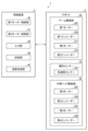
先ず、第1実施形態に係るロボットシステムの構成について、図1、図2、および図3を参照して説明する。図1は、第1実施形態に係るロボットシステムの全体構成を示す図である。図2は、第1実施形態に係るロボットシステムに適用されるロボットの概略図である。なお、図1ではエンドエフェクターの図示は省略されている。また、図2ではエンドエフェクターおよび対象物を模式的に示している。
1. First Embodiment 1.1: Overall Configuration of the Robot System According to the First Embodiment First, the configuration of the robot system according to the first embodiment will be described with reference to FIGS. 1, 2, and 3. FIG. 1 is a diagram showing the overall configuration of a robot system according to a first embodiment. FIG. 2 is a schematic diagram of a robot applied to the robot system according to the first embodiment. Note that in FIG. 1, illustration of the end effector is omitted. Moreover, in FIG. 2, the end effector and the target object are schematically shown.
図1、および図2に示すように、第1実施形態に係るロボットシステム1は、ロボット2と、ロボット2を制御する制御装置3とを備えている。これにより、ロボットシステム1は、後述する制御装置3の利点を有することができる。ロボットシステム1の用途は、特に限定されず、例えば、電子部品および電子機器等の対象物の保持、搬送、組立および検査等の各作業で用いることができる。
As shown in FIGS. 1 and 2, the
ロボット2は、スカラロボットとも呼ばれる水平多関節ロボットであり、基台21と、基台21に設けられ基台21に対して回動軸である第1回動軸J1周りに回動可能なアーム22と、アーム22に設けられた作業ヘッド25と、を有する。また、ロボット2は、アーム22を回動軸である第2回動軸J2周りに駆動させるアーム駆動部26と、作業ヘッド25を駆動させる作業ヘッド駆動部28と、を有する。また、ロボット2は、第2回動軸J2と異なる位置に設けられ、作業ヘッド25にあって第2回動軸J2と平行に移動し、下方の一端側にエンドエフェクター4が設けられるシャフトであるスプラインシャフト253と、アーム22に設けられ、第2回動軸J2の軸方向と直交し、かつ、第2回動軸J2とスプラインシャフト253の回動軸である第3回動軸J3とを含む平面である仮想平面VPに平行な軸でありアーム22のロール軸である第3角速度検出軸A3周りの角速度ωA3を検出する慣性センサー20の一例としての角速度センサー201(図3参照)と、を有する。
The
制御装置3は、アーム駆動部26に含まれる第1モーター261の作動を制御する第1モーター制御部30および第2モーター271の作動を制御する第2モーター制御部31を備えている(図3参照)。第1モーター制御部30は、アーム22が第2回動軸J2周りに回動した際に、角速度センサー201の検出した角速度ωA3に基づいて第1モーター261を制御する、所謂フィードバック制御を行う。第1モーター制御部30は、このフィードバック制御により第1モーター261の作動を制御し、作業ヘッド25のスプラインシャフト253に生じる振動、例えばスプラインシャフト253に生じるエンドエフェクター4側の制御点P1の振動を抑制することができる。
The
このようなロボットシステム1によれば、後述するように、アーム22が第1回動軸J1周りに回動して停止した後のアーム22の振動を抑制し、例えばスプラインシャフト253の制御点P1の位置をできる限り一定に維持することができる。これにより、エンドエフェクター4で対象物Wを把持する際、その把持を安定して行うことができる。
According to such a
以下、ロボット2の構成について、さらに詳細に説明する。
基台21は、例えば図示しない床面にボルト等によって固定されている。アーム22は、基台21に連結され、基台21に対して第1回動軸J1周りに回動可能な第1アーム23と、第1アーム23の先端部に設けられ、第1アーム23に対して第1回動軸J1と平行な第2回動軸J2周りに回動可能に連結されている第2アーム24と、を有する。
The configuration of the
The
なお、第1アーム23は、例えば樹脂などの柔軟性を有する部材を、その外表面を構成する部材に含むことが好ましい。この樹脂には、例えば、ポリ塩化ビニル・ポリエチレンなどの熱可塑性樹脂、フェノール樹脂・メラミン樹脂などの熱硬化性樹脂と、または天然ゴムや合成ゴムなどを例示することができる。第1アーム23は、外表面に樹脂などを用いることにより、樹脂の柔軟性による緩衝作用により、回動する第1アーム23が他の部位と接触した場合の接触衝撃を小さくすることができる。なお、アーム22は、角速度センサー201の検出した角速度ωA3に基づいて第1モーター261に対してフィードバック制御を行い、第1モーター261の作動を制御することによって、作業ヘッド25のスプラインシャフト253に生じる振動を抑制することができる。したがって、上述したように、アーム22は、外表面を柔軟な樹脂で構成した第1アーム23としても、作業ヘッド25のスプラインシャフト253に生じる振動を増加させることが無い。
Note that it is preferable that the
また、基台21内には基台21に対して第1アーム23を、その回動軸としての第1回動軸J1周りに回動させる第1モーター261が設けられている。また、第1モーター261には、第1モーター261の回転量を検出する角度センサーとしての第1エンコーダー262が設けられており、第1エンコーダー262からの出力によって基台21に対する第1アーム23の回動角を検出することができる。
Further, a
また、第2アーム24内には第1アーム23に対して第2アーム24を、その回動軸としての第2回動軸J2周りに回動させる第2モーター271が設けられている。また、第2モーター271には、第2モーター271の回転量を検出する角度センサーとしての第2エンコーダー272が設けられており、第2エンコーダー272からの出力によって第1アーム23に対する第2アーム24の回動角を検出することができる。図3に示すように、アーム駆動部26は、第1モーター261と、第1エンコーダー262と、第2モーター271と、第2エンコーダー272とを有する構成となっている。
Further, a
作業ヘッド25は、第2アーム24の先端部、すなわち、第2アーム24の回動軸としての第2回動軸J2と異なる位置に設けられている。作業ヘッド25は、第2アーム24の先端部に同軸的に配置されたスプラインナット251およびボールネジナット252と、スプラインナット251およびボールネジナット252に挿通されたスプラインシャフト253と、を有する。
The
スプラインシャフト253は、第2アーム24に対して、その中心軸である第3回動軸J3周りに回動可能であり、かつ、第3回動軸J3に沿った方向、換言すれば第3回動軸J3と平行な方向に往復移動が可能となっている。なお、第1回動軸J1、第2回動軸J2および第3回動軸J3は、互いに平行であり、それぞれ、鉛直方向に沿っている。
The
また、第2アーム24内には、スプラインナット251を回転させてスプラインシャフト253を第3回動軸J3周りに回転させる第3モーター281が設けられている。また、第3モーター281には、第3モーター281の回転量を検出する角度センサーとしての第3エンコーダー282が設けられており、第3エンコーダー282からの出力によって第2アーム24に対するスプラインシャフト253の回転量を検出することができる。また、第2アーム24内には、ボールネジナット252を回転させてスプラインシャフト253を第3回動軸J3に沿った方向に移動させる第4モーター291が設けられている。また、第4モーター291には、第4モーター291の回転量を検出する角度センサーとしての第4エンコーダー292が設けられており、第4エンコーダー292からの出力によって第2アーム24に対するスプラインシャフト253の移動量を検出することができる。図3に示すように、作業ヘッド駆動部28は、第3モーター281と、第3エンコーダー282と、第4モーター291と、第4エンコーダー292とを有する構成となっている。
Further, a
図1および図2に示すように、スプラインシャフト253の下端側の先端部には、エンドエフェクター4を装着するためのペイロード254が設けられている。ペイロード254に装着するエンドエフェクター4としては、特に限定されず、例えば、対象物Wを保持するハンドや対象物Wを加工する作業具等が挙げられる。なお、ハンドによる対象物Wの保持には、把持、および吸着を含む。
As shown in FIGS. 1 and 2, a
慣性センサー20の一例としての角速度センサー201(図3参照)は、第2アーム24内に設けられている。特に、本実施形態における角速度センサー201は、第2アーム24の先端部であるスプラインシャフト253の近傍に設けられている。なお、第1回動軸J1と慣性センサー20との間の距離、本構成では第1回動軸J1と角速度センサー201との間の距離を、距離Lとする。
An angular velocity sensor 201 (see FIG. 3) as an example of the
このように、角速度センサー201が第2アーム24の先端部に設けられることにより、第1モーター261と角速度センサー201との距離Lが大きくなり、第2アーム24のロール軸である第3角速度検出軸A3周りの振動を、より振動の大きな部位において検出することができ、角速度ωA3の検出感度を高めることができる。
In this way, by providing the
図2に示すように、角速度センサー201は、第2アーム24が第2回動軸J2周りに回動、または、第2アーム24の回動が停止した状態で、第1アーム23が第1回動軸J1周りに回動した際に、第2アーム24における三つの軸周りの角速度を検出することができる。以下では、「第1アーム23が第1回動軸J1周りに回動した際に、アーム22のロール軸周りに生じる角速度」を代表とする。
As shown in FIG. 2, the
なお、三つの軸のうちの一つ目の軸は、図2中の第1角速度検出軸A1であり、二つ目の軸は、第2角速度検出軸A2であり、三つ目の軸は、第3角速度検出軸A3である。また、このような角速度センサー201としては、例えばジャイロセンサーで構成されているのが好ましい。
Note that the first axis of the three axes is the first angular velocity detection axis A1 in FIG. 2, the second axis is the second angular velocity detection axis A2, and the third axis is , the third angular velocity detection axis A3. Moreover, it is preferable that such an
第1角速度検出軸A1は、第2回動軸J2と第3回動軸J3とを含む平面である仮想平面VP、すなわち、図2の紙面に直交する軸であり、図2に示すY軸に沿った軸である。この第1角速度検出軸A1周りの角速度、換言すれば、ピッチ方向の角速度を「第1角速度ωA1」と言うことがある。 The first angular velocity detection axis A1 is a virtual plane VP that is a plane including the second rotation axis J2 and the third rotation axis J3, that is, an axis perpendicular to the paper surface of FIG. 2, and is the Y axis shown in FIG. is the axis along. The angular velocity around this first angular velocity detection axis A1, in other words, the angular velocity in the pitch direction is sometimes referred to as "first angular velocity ωA1."
第2角速度検出軸A2は、第1角速度検出軸A1と直交する、すなわち、第2回動軸J2の軸方向と平行な軸であり、図2に示すZ軸に沿った軸である。この第2角速度検出軸A2周りの角速度、換言すれば、ヨー方向の角速度を「第2角速度ωA2」と言うことがある。 The second angular velocity detection axis A2 is an axis that is perpendicular to the first angular velocity detection axis A1, that is, parallel to the axial direction of the second rotation axis J2, and is an axis along the Z axis shown in FIG. 2. The angular velocity around this second angular velocity detection axis A2, in other words, the angular velocity in the yaw direction is sometimes referred to as "second angular velocity ωA2."
第3角速度検出軸A3は、第1角速度検出軸A1と第2角速度検出軸A2とに直交する、すなわち、第2回動軸J2の軸方向と直交し、かつ、仮想平面VPに平行な軸であり、図2に示すX軸に沿った軸である。この第3角速度検出軸A3周りの角速度、換言すれば、アーム22のロール方向の角速度を「第3角速度ωA3」と言うことがある。
The third angular velocity detection axis A3 is an axis that is perpendicular to the first angular velocity detection axis A1 and the second angular velocity detection axis A2, that is, perpendicular to the axial direction of the second rotation axis J2, and parallel to the virtual plane VP. , which is an axis along the X axis shown in FIG. The angular velocity around this third angular velocity detection axis A3, in other words, the angular velocity in the roll direction of the
このように角速度センサー201は、仮想平面VPに直交する第1角速度検出軸A1周りの第1角速度ωA1を検出することができる。これにより、例えば第1角速度ωA1の情報を、スプラインシャフト253のZ軸に沿った上下方向の振動抑制制御に用いることができる。
In this way, the
また、角速度センサー201は、第2回動軸J2に平行な第2角速度検出軸A2周りの第2角速度ωA2も検出することができる。これにより、例えば第2角速度ωA2の情報を、スプラインシャフト253の水平方向の振動抑制制御に用いることができる。
Furthermore, the
また、角速度センサー201は、アーム22のロール軸と平行な第3角速度検出軸A3周りの第3角速度ωA3を検出することができる。この第3角速度ωA3は、スプラインシャフト253の第3角速度検出軸A3周りの振動抑制制御に用いられる。この制御については、後述する。
Further, the
角速度センサー201としては、角速度を検出することができれば、特に限定されず、例えば、圧電体の変形により生じる電荷から角速度を検出する角速度センサー、静電容量の変化から角速度を検出する角速度センサー等を用いることができる。なお、本実施形態では、角速度センサー201として水晶振動子を用いている。この水晶振動子は、振動腕を有しており、振動腕を駆動振動モードで振動させている状態で、第1角速度検出軸A1、第2角速度検出軸A2および第3角速度検出軸A3のいずれかの検出軸周りの角速度が加わると、コリオリの力によって振動腕に検出振動モードが励振され、この検出振動モードに応じた検出信号を出力するようになっている。そのため、水晶振動子から出力される検出信号に基づいて、各検出軸周りの角速度を検出することができる。
The
図3に示すように、制御装置3は、ロボット2のアーム駆動部26、作業ヘッド駆動部28および慣性センサー20と電気的に接続され、これらの各部の作動を制御する第1モーター制御部30および第2モーター制御部31を有する。ロボット2と制御装置3とは、ケーブルで電気的に接続されている。ただし、ロボット2と制御装置3とは、有線方式の接続に限らず、例えば、ケーブルを省略し、無線方式で接続してもよい。また、制御装置3は、その一部または全部がロボット2に内蔵されていてもよい。
As shown in FIG. 3, the
第1モーター制御部30や第2モーター制御部31などを含む制御装置3としては、例えば、プロセッサーの一例であるCPU(Central Processing Unit)が内蔵されたコンピューター(PC:personal computer)等で構成することができる。これにより、制御装置3は、ロボット2の各部を制御することができる。
The
また、図3に示すように、制御装置3は、各種情報(諸条件)を記憶する記憶部39と、各種情報(諸条件)を入力する入力部38と、を備えている。
Further, as shown in FIG. 3, the
記憶部39には、例えば、ロボット2を動作させるプログラムや、アーム22が第2回動軸J2周りに回動した際に、角速度センサー201の検出した角速度ωA3に基づいて第1モーター261に対してフィードバック制御する制御プログラムや、入力部38を介して入力された情報、および定義されている感度補正量などを記憶することができる。
The
入力部38は、ロボット2の動作に必要な情報を入力することができる。この入力部38としては、特に限定されず、例えば、キーボードやタッチパネル等で構成することができる。
The
1.2.第1実施形態に係る、アームの振動を抑制する制御方法および制御装置
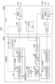
次に、スプラインシャフト253の第3角速度検出軸A3周りの振動を抑制する制御方法について、図1~図3に加え、図4、図5A、および図5Bを参照して説明する。図3は、第1実施形態に係るロボットシステムの制御系を示すブロック図である。図4は、第1実施形態に係るロボットシステムの回路系を示すブロック図である。図5Aは、アームの動作ステップを説明する図1中のQ2視図である。図5Bは、アームの動作ステップを説明する図1中のQ1視図である。なお、以下説明する本形態におけるアームの振動を抑制する制御方法では、アーム22のロール軸周りの角速度ωA3を、慣性センサー20の一例としての角速度センサー201によって検出する検出工程と、検出した角速度に基づいて、第1モーター261を制御する制御工程と、を含む。
1.2. Control method and control device for suppressing arm vibration according to first embodiment Next, in addition to FIGS. 4, FIG. 5A, and FIG. 5B. FIG. 3 is a block diagram showing a control system of the robot system according to the first embodiment. FIG. 4 is a block diagram showing a circuit system of the robot system according to the first embodiment. FIG. 5A is a Q2 view in FIG. 1 illustrating the operation steps of the arm. FIG. 5B is a Q1 view in FIG. 1 illustrating the operation steps of the arm. In addition, in the control method for suppressing vibration of the arm in this embodiment described below, a detection step of detecting the angular velocity ωA3 around the roll axis of the
第1アーム23および第2アーム24を含むアーム22は、例えば、図5AのStep1に示す初期位置から、矢印a1で示す第1回動軸J1周りに所定角度回動し、二点鎖線で示すアーム22aの位置に停止した際に、第3角速度検出軸A3周り、すなわち、アーム22のロール方向に振動する。なお、図5AのStep2が、この停止した際の状態を示している。そして、図5BのStep2AおよびStep2Bに示すように、アーム22を構成する第2アーム24の先端部に設けられているスプラインシャフト253も、この第2アーム24とともに、例えばスプラインシャフト253aからスプラインシャフト253aaの間において矢印b1のように、第3角速度検出軸A3周りに振動することになる。なお、図5Bでは、スプラインシャフト253の停止目標位置を位置Pで示している。そして、角速度センサー201では、この第3角速度検出軸A3周りの振動と等価な角速度ωA3を検出することができる。
The
アーム22を構成する第2アーム24が、第3角速度検出軸A3周りに振動した際、その振動が大きければ大きい程、制御点P1での振幅、換言すれば制御点P1での変位量も大きくなり、その結果、制御点P1の位置が定まらないおそれがある(図5B:Step2B参照)。そして、この状態で、例えば、エンドエフェクター4で対象物Wを把持しようとしても、その把持を行うことが困難となるおそれがある。
When the
そこで、制御装置3では、角速度センサー201の検出したアーム22のロール軸周りの角速度ωA3に基づいて第1モーター261を制御する、所謂フィードバック制御を行い、第1モーター261の作動を制御することによって、スプラインシャフト253の第3角速度検出軸A3周りの振動の抑制を行う。
Therefore, the
このフィードバック制御では、角速度センサー201の検出したアーム22のロール軸周りの角速度ωA3の方向と大きさに基づいて、その角速度ωA3を相殺する方向にアーム22が移動するように第1モーター261の作動を制御する。すなわち、制御装置3は、速度制御として第1モーター261の作動を制御し、図5AのStep3および図5BのStep3の矢印a2に示す方向にアーム22aを移動させることによって角速度ωA3を相殺する。その結果、第2アーム24aの先端部に設けられているスプラインシャフト253aは、図5AのStep3および図5BのStep3に示す第2アーム24bのスプラインシャフト253bの位置となる。
In this feedback control, based on the direction and magnitude of the angular velocity ωA3 of the
その後、制御装置3は、アーム22の位置制御として第1モーター261の作動を制御し、図5AのStep4および図5BのStep4の矢印a3に示す方向にアーム22bをアーム22cの位置に移動させ、停止目標位置である位置Pにスプラインシャフト253cを停止する。このように、制御装置3は、このアーム22、すなわちスプラインシャフト253の振動の抑制により、制御点P1の停止位置が、できる限り一定となる制御を可能に構成されている。
After that, the
なお、制御装置3は、フィードバック制御として、角速度ωA3に基づいてその角速度ωA3を相殺する方向にアーム22が移動するように第1モーター261の作動を制御する速度制御と、速度制御によって生じる位置ずれを予測してアーム22を目標位置に移動させる位置制御とを、並行して行ってもよい。
As feedback control, the
このような構成として、制御装置3は、図4に示すように、第1モーター制御部30と、第2モーター制御部31と、微分回路401と、感度補正量処理部402と、フィードバック量算出部403と、を有している。
As shown in FIG. 4, the
第1モーター制御部30は、位置制御部としての第1位置制御部301および速度制御部としての第1速度制御部302を含み、第1アーム23を第1回動軸J1周りに回動させる第1モーター261の作動を制御する。また、第1モーター制御部30は、アーム22が第2回動軸J2周りに回動した際に、角速度センサー201の検出した角速度ωA3に基づいて、第1モーター261を制御する、所謂フィードバック制御を行う。ここで、第1モーター261は、第1モーター制御部30の作動制御により、減速機263を介して第1アーム23を回動させることができる。
The first
具体的には、第1速度制御部302は、角速度センサー201の検出したアーム22のロール軸周りの角速度ωA3の方向と大きさに基づいて、その角速度ωA3を相殺する方向にアーム22が移動するように第1モーター261の作動を制御する。すなわち、制御装置3は、速度制御として第1モーター261の作動を制御し、角速度ωA3の発生する方向にアーム22を移動させることによって角速度ωA3を相殺し、角速度ωA3を低減する。
Specifically, the first
その後、第1位置制御部301は、角速度ωA3を相殺し、角速度ωA3を低減するために第1速度制御部302によって移動した分の距離を、目標位置に戻す位置制御を行う。これにより、第2アーム24の先端部、換言すればスプラインシャフト253を目標位置に移動させる。
Thereafter, the first position control unit 301 performs position control to cancel the angular velocity ωA3 and return the distance moved by the first
これらにより、第1速度制御部302が角速度センサー201からの出力に基づいて第1モーター261の速度を制御することにより、角速度ωA3による第2アーム24のロール軸周りの振動を抑制し、第1位置制御部301が振動によってずれた分を位置制御で目標位置に移動させる。これにより、第2アーム24の先端部をより短時間に、且つより正確に目標位置に到達させることができる。
As a result, the first
第1位置制御部301は、例えば予め記憶部39に記憶されている位置指令に基づいて第1アーム23を第1回動軸J1周りに回動させる第1モーター261への速度指令を生成する部分である。
The first position control unit 301 generates a speed command to the
第1速度制御部302は、第1位置制御部301で生成された速度指令に基づいて第1モーター261を駆動する電流指令を生成する部分である。
The first
第2モーター制御部31は、位置制御部としての第2位置制御部311および速度制御部としての第2速度制御部312を含み、第2アーム24を第1回動軸J1周りに回動させる第2モーター271の作動を制御する。ここで、第2モーター271は、第2モーター制御部31の作動制御により、減速機273を介して第2アーム24を回動させることができる。
The second
第2位置制御部311は、例えば予め記憶部39に記憶されている位置指令に基づいて第2アーム24を第2回動軸J2周りに回動させる第2モーター271への速度指令を生成する部分である。
The second
第2速度制御部312は、第2位置制御部311で生成された速度指令に基づいて第2モーター271を駆動する電流指令を生成する部分である。
The second
微分回路401は、第2エンコーダー272からの出力によって得られた第1アーム23の第1回動軸J1周りの回動角度を微分する部分である。この微分されることにより生成された指令である角速度指令は、第1速度制御部302に入力されて、第1モーター261を駆動する電流指令に重畳される。
The
感度補正量処理部402は、角速度センサー201の検出した角速度ωA3に対して、定義してあった感度補正量をかけ、フィードバック制御に使用可能な制御量とする処理を行う。この処理として、本実施形態では、角速度ωA3に係数k1を乗じる。なお、係数k1は、0を超える任意の数値である。例えば、0<k1<1の場合、角速度ωA3は、感度補正量処理部402で減少される。これに対し、感度補正量処理部402での補正を省略した場合には、角速度ωA3がそのままの大きさで、すなわち、減少されずにフィードバック量算出部403に入力されてしまい、その結果、第1アーム23の第1回動軸J1周りの円滑な回動が困難となるおそれがある。
The sensitivity correction
フィードバック量算出部403は、感度補正量処理部402で処理した角速度ωA3に基づく制御量から角速度フィードバック値を算出し、第1速度制御部302に送る。すなわち、角速度センサー201の検出した角速度ωA3に基づくフィードバックは、第1位置制御部301には行わず、第1速度制御部302に対して行う。
The feedback
なお、ロボット2には、第1アーム23の第1回動軸J1周りの回動や第2アーム24の第2回動軸J2周りの回動による外乱振動が入ってきてもよい。
Note that disturbance vibrations may enter the
このようなロボット2を制御する制御方法では、角速度センサー201の検出した角速度ωA3に基づくフィードバック制御によって、第1アーム23を回動する第1モーター261が、位置指令および速度指令に合った駆動状態となる。そして、この駆動状態は、第2アーム24の先端部に設けられているスプラインシャフト253の第3角速度検出軸A3周りの移動が相殺され、振動を抑制することができる状態となっている。これにより、スプラインシャフト253の位置が、短時間で定まることとなる。
In such a control method for controlling the
以上、説明した第1実施形態に係るロボットシステム1によれば、第1モーター制御部30は、慣性センサー20の一例である角速度センサー201の検出したアーム22のロール軸周りの角速度ωA3に基づいて第1モーター261に対しフィードバック制御を行う。このフィードバック制御は、第2アーム24の先端部に設けられているスプラインシャフト253に生じるアーム22のロール軸周りの振動を抑制するように第1モーター261の作動を制御することから、第2アーム24の先端部に設けられているスプラインシャフト253の振動を抑制し、スプラインシャフト253の位置を短時間で定めることができる。
According to the
なお、上述では、角速度センサー201を第2アーム24の先端部側に設ける構成例を示して説明したが、角速度センサー201の設置位置はこれに限らない、角速度センサー201は、例えば、作業ヘッド25、もしくはスプラインシャフト253に設けてもよいし、第1アーム23に設けてもよい。なお、角速度センサー201を第1アーム23に設ける場合、角速度センサー201は、その検出感度を向上させるため、第1アーム23の回動軸である第1回動軸J1からできるだけ離れた位置に設けることが望ましい。
In the above description, the
2.第2実施形態
2.1.第2実施形態に係るロボットシステムの全体構成
次に、第2実施形態に係るロボットシステムの構成について、図6、図7、図8、および図9を参照して説明する。図6は、第2実施形態に係るロボットシステムの加速度センサーの配置例を説明する概略図である。図7は、第2実施形態に係るロボットシステムの制御系を示すブロック図である。図8は、第2実施形態に係るロボットシステムの回路系の実施例1を示すブロック図である。図9は、第2実施形態に係るロボットシステムの回路系の実施例2を示すブロック図である。
2. Second embodiment 2.1. Overall configuration of the robot system according to the second embodiment Next, the configuration of the robot system according to the second embodiment will be described with reference to FIGS. 6, 7, 8, and 9. FIG. 6 is a schematic diagram illustrating an example of the arrangement of acceleration sensors in the robot system according to the second embodiment. FIG. 7 is a block diagram showing a control system of the robot system according to the second embodiment. FIG. 8 is a block diagram showing Example 1 of the circuit system of the robot system according to the second embodiment. FIG. 9 is a block diagram showing Example 2 of the circuit system of the robot system according to the second embodiment.
図7に示すように、第2実施形態に係るロボットシステム100a,100bは、前述の第1実施形態に係るロボットシステム1に対し、ロボット200a,200bに設けられている慣性センサー20として加速度センサー202a,202bを用いているところが異なっている。また、これに伴って、第2実施形態に係るロボットシステム100a,100bでは、制御装置300a,300bの構成が異なっている。ロボットシステム100a,100bの他の構成については、前述の第1実施形態に係るロボットシステム1と同様である。したがって、以下では、ロボットシステム1と同様な構成の詳細な説明を省略することがある。また、ロボットシステム1と同様な構成部位は、同名称および同符号を付して説明する。
As shown in FIG. 7, the
図7に示すように、第2実施形態に係るロボットシステム100a,100bは、ロボット200a,200bに慣性センサー20として加速度センサー202a,202bを用いている。なお、加速度センサー202a,202bは、アーム22のロール方向である捻れ方向の加速度を検出するため、第1アーム23の第1回動軸J1および第2アーム24の第2回動軸J2に対して、離れた位置に取り付けられていることが望ましい。
As shown in FIG. 7,
また、加速度センサー202a,202bは、その取り付け位置によって、検出する加速度の方向が異なる。図6には、図1のQ1方向から見た場合の、第2アーム24への加速度センサー202a,202bの取り付け位置が示されている。図6では、アーム22のロール軸である第2アーム24の第3角速度検出軸A3の上側に加速度センサー202aが取り付けられている実施例1と、第2アーム24の第3角速度検出軸A3の水平面上に加速度センサー202bが取り付けられている実施例2と、を例示している。なお、第2アーム24には、鉛直方向であるZ方向に沿ってスプラインシャフト253が設けられ、その下端に対象物Wが把持されている。
Furthermore, the
実施例1に係る加速度センサー202a、および実施例2に係る加速度センサー202bは、いずれもアーム22のロール軸である第2アーム24の第3角速度検出軸A3を中心とした円c1,c2の、それぞれの接線方向f1,f2の加速度を検出する。そして、後段にて説明する制御装置300a,300bは、加速度センサー202a,202bの検出した加速度に基づいて第1モーター261を制御する、所謂フィードバック制御を行い、第1モーター261の作動を制御する。この第1モーター261の作動の制御により、作業ヘッド25のスプラインシャフト253(図2参照)に生じる振動、例えばスプラインシャフト253に生じるエンドエフェクター4側の制御点P1(図2参照)の振動を抑制することができる。
The
ロボット200a,200bは、スカラロボットとも呼ばれる水平多関節ロボットであり、その構成は、第1実施形態のロボット2と同様であるので詳細な説明を省略する。なお、ロボット200a,200bは、基台21に連結され、基台21に対して第1回動軸J1周りに回動可能な第1アーム23と、第1アーム23の先端部に設けられ、第1アーム23に対して第1回動軸J1と平行な第2回動軸J2周りに回動可能に連結されている第2アーム24と、を有する。なお、第1アーム23は、第1実施形態と同様に、例えば樹脂などの柔軟性を有する部材を、その外表面を構成する部材に含んでいる。
The
以下、実施例1に係る加速度センサー202aの構成例、および実施例2に係る加速度センサー202bの構成例を順次説明する。以下説明する本形態におけるアームの振動を抑制する制御方法では、アーム22のロール軸周りの加速度を、慣性センサー20の一例としての加速度センサー202a,202bによって検出する検出工程と、検出した加速度に基づいて、第1モーター261を制御する制御工程と、を含む。
Hereinafter, a configuration example of the
2.2.実施例1に係る、アームの振動を抑制する制御方法および制御装置
第2実施形態の実施例1に係るロボットシステム100aを構成する加速度センサー202aは、図6に示すように、アーム22のロール軸である第2アーム24の第3角速度検出軸A3の上側に取り付けられ、第3角速度検出軸A3を中心とした円c1の接線方向f1、すなわち水平方向の加速度を検出する。
2.2. Control Method and Control Device for Suppressing Arm Vibration According to Example 1 The
水平方向の加速度を検出する加速度センサー202aは、第3角速度検出軸A3の上側に取り付けられていることから、ロール方向の捻れ振動成分以外の、ロボットアーム駆動によるアーム角速度も検出してしまう。この課題に対して、ロボットシステム100aでは、第1モーター261の角速度から算出されるアーム先端角速度と、加速度センサー202aの設置場所のアーム先端角速度との差分を取ることによって、加速度センサー202aにおける捻れ振動成分のみの検出値としている。
Since the
図8に示すように、実施例1に係る構成のロボットシステム100aは、ロボット200aと、制御装置300aと、を有している。ロボット200aは、図7に示したように第1実施形態と同様構成のアーム駆動部26および作業ヘッド駆動部28と、慣性センサー20を有している。本実施例1での慣性センサー20は、加速度センサー202aである。
As shown in FIG. 8, a
制御装置300aは、第1モーター制御部30と、第2モーター制御部31と、入力部38と、記憶部39と、演算処理部40(図7参照)とを有している。演算処理部40は、微分回路401と、感度補正量処理部402と、フィードバック量算出部403と、積分回路404と、センサー角速度算出部405と、微分回路406と、モーター角速度算出部407と、を有している。
The
第1モーター制御部30は、第1位置制御部301および第1速度制御部302を含み、第1アーム23を第1回動軸J1周りに回動させる第1モーター261の作動を制御する。また、第1モーター制御部30は、アーム22が第2回動軸J2周りに回動した際に、加速度センサー202aの検出した加速度から算出された角速度に基づいて、第1モーター261を制御する、所謂フィードバック制御を行う。ここで、第1モーター261は、第1モーター制御部30の作動制御により、減速機263を介して第1アーム23を回動させることができる。
The first
具体的には、第1速度制御部302は、加速度センサー202aの検出した加速度から角速度を算出し、その角速度を相殺する方向にアーム22が移動するように第1モーター261の作動を制御する。すなわち、制御装置3は、速度制御として第1モーター261の作動を制御し、角速度の発生する方向にアーム22を移動させることによって角速度を相殺し、角速度を低減する。
Specifically, the first
その後、第1位置制御部301は、角速度を相殺し、低減するために第1速度制御部302によって移動した分の距離を、目標位置に戻す位置制御を行う。これにより、第2アーム24の先端部、換言すればスプラインシャフト253を目標位置に移動させる。
Thereafter, the first position control section 301 performs position control to return the distance moved by the first
これらにより、第1速度制御部302が加速度センサー202aからの出力に基づいて第1モーター261の速度を制御することにより、角速度による第2アーム24のロール軸周りの振動を抑制し、第1位置制御部301が振動によってずれた分を位置制御で目標位置に移動させる。これにより、第2アーム24の先端部をより短時間に、且つより正確に目標位置に到達させることができる。
As a result, the first
第1位置制御部301は、例えば予め記憶部39に記憶されている位置指令に基づいて第1アーム23を第1回動軸J1周りに回動させる第1モーター261への速度指令を生成する部分である。
The first position control unit 301 generates a speed command to the
第1速度制御部302は、第1位置制御部301で生成された速度指令に基づいて第1モーター261を駆動する電流指令を生成する部分である。
The first
第2モーター制御部31は、第2位置制御部311および第2速度制御部312を含み、第2アーム24を第1回動軸J1周りに回動させる第2モーター271の作動を制御する。ここで、第2モーター271は、第2モーター制御部31の作動制御により、減速機273を介して第2アーム24を回動させることができる。
The second
第2位置制御部311は、例えば予め記憶部39に記憶されている位置指令に基づいて第2アーム24を第2回動軸J2周りに回動させる第2モーター271への速度指令を生成する部分である。
The second
第2速度制御部312は、第2位置制御部311で生成された速度指令に基づいて第2モーター271を駆動する電流指令を生成する部分である。
The second
微分回路401は、第2エンコーダー272からの出力によって得られた第1アーム23の第1回動軸J1周りの回動角度を微分する部分である。この微分されることにより生成された指令である角速度指令は、第1速度制御部302に入力されて、第1モーター261を駆動する電流指令に重畳される。
The
積分回路404は、加速度センサー202aによって得られた第2アーム24の先端部、すなわちアーム22の先端部の先端加速度を積分し、速度情報に変換する部分である。この積分により生成されたアーム22先端の水平方向における速度情報である先端速度は、センサー角速度算出部405に入力されて、アーム22先端の水平方向のセンサー角速度に変換される。
The integrating
センサー角速度算出部405は、積分回路404から出力されたアーム22の先端速度を、1/Lを用いた処理により、アーム22の先端部における水平方向のセンサー角速度を算出する。ここで、Lは、図1に示すように、第1モーター261の第1回動軸J1から加速度センサー202aまでの距離である。
The sensor angular
微分回路406は、第2エンコーダー272からの出力によって得られた第1アーム23の第1回動軸J1周りの回動角度を微分する部分である。
The
モーター角速度算出部407は、微分回路406から出力された第1アーム23における第1回動軸J1周りの回動角度の微分値に、減速機263の減速比率を乗算し、アーム22の先端部におけるモーター角速度を算出する。
The motor angular
そして演算処理部40は、センサー角速度算出部405の算出したセンサー角速度と、モーター角速度算出部407の算出したモーター角速度との差分を取り、アーム22のロール軸周りの振動成分のみの角速度を生成する。
Then, the
感度補正量処理部402は、加速度センサー202aの検出した加速度から、積分回路404と、センサー角速度算出部405と、微分回路406と、モーター角速度算出部407とによって算出された、アーム22のロール軸周りの振動成分のみの角速度に対して、定義してあった感度補正量をかけ、フィードバック制御に使用可能な制御量とする処理を行う。この処理として、本実施形態では、角速度に係数k1を乗じる。なお、係数k1は、0を超える任意の数値である。例えば、0<k1<1の場合、角速度は、感度補正量処理部402で減少される。これに対し、感度補正量処理部402での補正を省略した場合には、角速度がそのままの大きさで、すなわち、減少されずにフィードバック量算出部403に入力されてしまい、その結果、第1アーム23の第1回動軸J1周りの円滑な回動が困難となるおそれがある。
The sensitivity correction
フィードバック量算出部403は、感度補正量処理部402で処理した水平方向の振動成分の角速度に基づく制御量から角速度フィードバック値を算出し、第1速度制御部302に送る。すなわち、加速度センサー202aの検出した加速度から算出された水平方向の振動成分の角速度に基づくフィードバックは、第1位置制御部301には行わず、第1速度制御部302に対して行う。
The feedback
このようなロボット200aおよび制御装置300aを用いたロボットシステム100aの制御方法では、加速度センサー202aの検出した加速度から算出された水平方向の振動成分の角速度に基づくフィードバック制御によって、第1アーム23を回動する第1モーター261が、位置指令および速度指令に合った駆動状態となる。そして、この駆動状態は、第2アーム24の先端部に設けられているスプラインシャフト253の第3角速度検出軸A3周りの移動が相殺され、振動を抑制することができる状態となっている。これにより、スプラインシャフト253の位置が、短時間で定まることとなる。
In the control method for the
以上、説明した第2実施形態の実施例1に係るロボットシステム100aによれば、第1モーター制御部30は、慣性センサー20の一例である加速度センサー202aの検出したアーム22の水平方向の加速度から算出された水平方向の振動成分の角速度に基づいて第1モーター261に対しフィードバック制御を行う。このフィードバック制御は、第2アーム24の先端部に設けられているスプラインシャフト253に生じるアーム22のロール軸周りの振動を抑制するように第1モーター261の作動を制御することから、第2アーム24の先端部に設けられているスプラインシャフト253の振動を抑制し、スプラインシャフト253の位置を定めることができる。
According to the
2.3.実施例2に係る、アームの振動を抑制する制御方法および制御装置
第2実施形態の実施例2に係るロボットシステム100bを構成する加速度センサー202bは、図6に示すように、アーム22のロール軸である第2アーム24の第3角速度検出軸A3の図中Y軸に沿った水平面上に取り付けられ、第3角速度検出軸A3を中心とした円c2の接線方向f2、すなわち垂直方向の加速度を検出する。
2.3. Control Method and Control Device for Suppressing Arm Vibration According to Second Embodiment The
垂直方向の加速度を検出する加速度センサー202bは、第3角速度検出軸A3の水平面上に取り付けられていることから、重力W1の影響を考慮する必要があり、常に重力との差分を取る必要がある。この課題に対して、ロボットシステム100bでは、加速度センサー202bの検出した加速度と、アーム22と把持されている対象物Wとに係る重力W1との差分を取ることによって、加速度センサー202bにおける捻れ振動成分のみの検出値としている。
Since the
演算処理部40は、加速度センサー202bの検出した加速度と、重力W1との差分を取り、この差分値を加速度センサー202bにおける捻れ振動成分のみの検出値として積分回路404に入力する。
The
図9に示すように、実施例2に係る構成のロボットシステム100bは、ロボット200bと、制御装置300b、を有している。ロボット200bは、第1実施形態と同様構成のアーム駆動部26および作業ヘッド駆動部28と、慣性センサー20(図7参照)としての加速度センサー202bと、を有している。
As shown in FIG. 9, a
制御装置300bは、第1モーター制御部30と、第2モーター制御部31と、入力部38と、記憶部39と、演算処理部40(図7参照)とを有している。演算処理部40は、微分回路401と、感度補正量処理部402と、フィードバック量算出部403と、積分回路404と、センサー角速度算出部405と、を有している。
The
第1モーター制御部30は、位置制御部としての第1位置制御部301および速度制御部としての第1速度制御部302を含み、第1アーム23を第1回動軸J1周りに回動させる第1モーター261の作動を制御する。また、第1モーター制御部30は、アーム22が第2回動軸J2周りに回動した際に、加速度センサー202bの検出した加速度から算出された角速度に基づいて、第1モーター261に対してフィードバック制御を行う。ここで、第1モーター261は、第1モーター制御部30の作動制御により、減速機263を介して第1アーム23を回動させることができる。
The first
具体的には、第1速度制御部302は、加速度センサー202bの検出した加速度から角速度を算出し、その角速度を相殺する方向にアーム22が移動するように第1モーター261の作動を制御する。すなわち、制御装置300bは、速度制御として第1モーター261の作動を制御し、角速度の発生する方向にアーム22を移動させることによって角速度を相殺し、角速度を低減する。
Specifically, the first
その後、第1位置制御部301は、角速度を相殺し、低減するために第1速度制御部302によって移動した分の距離を、目標位置に戻す位置制御を行う。これにより、第2アーム24の先端部、換言すればスプラインシャフト253を目標位置に移動させる。
Thereafter, the first position control section 301 performs position control to return the distance moved by the first
これらにより、第1速度制御部302が加速度センサー202bからの出力に基づいて第1モーター261の速度を制御することにより、角速度による第2アーム24のロール軸周りの振動を抑制し、第1位置制御部301が振動によってずれた分を位置制御で目標位置に移動させる。これにより、第2アーム24の先端部をより短時間に、且つより正確に目標位置に到達させることができる。
As a result, the first
第1位置制御部301は、例えば予め記憶部39に記憶されている位置指令に基づいて第1アーム23を第1回動軸J1周りに回動させる第1モーター261への速度指令を生成する部分である。
The first position control unit 301 generates a speed command to the
第1速度制御部302は、第1位置制御部301で生成された速度指令に基づいて第1モーター261を駆動する電流指令を生成する部分である。
The first
第2モーター制御部31は、第2位置制御部311および第2速度制御部312を含み、第2アーム24を第1回動軸J1周りに回動させる第2モーター271の作動を制御する。ここで、第2モーター271は、第2モーター制御部31の作動制御により、減速機273を介して第2アーム24を回動させることができる。
The second
第2位置制御部311は、例えば予め記憶部39に記憶されている位置指令に基づいて第2アーム24を第2回動軸J2周りに回動させる第2モーター271への速度指令を生成する部分である。
The second
第2速度制御部312は、第2位置制御部311で生成された速度指令に基づいて第2モーター271を駆動する電流指令を生成する部分である。
The second
微分回路401は、第2エンコーダー272からの出力によって得られた第1アーム23の第1回動軸J1周りの回動角度を微分する部分である。この微分されることにより生成された指令である角速度指令は、第1速度制御部302に入力されて、第1モーター261を駆動する電流指令に重畳される。
The
積分回路404は、加速度センサー202bによって得られた第2アーム24の先端部、すなわちアーム22の先端部の先端加速度と重力W1との差分をとった検出値を積分し、速度情報に変換する部分である。この積分により生成されたアーム22の先端の垂直方向における速度情報である先端速度は、センサー角速度算出部405に入力されて、アーム22先端の水平方向のセンサー角速度に変換される。
The
センサー角速度算出部405は、積分回路404から出力されたアーム22の先端速度を、アーム22の先端部における垂直方向のアーム22先端のセンサー角速度を算出する。
The sensor angular
感度補正量処理部402は、加速度センサー202bの検出した加速度から、積分回路404と、センサー角速度算出部405とによって算出された、アーム22のロール軸周りの振動成分のみの角速度に対して、定義してあった感度補正量をかけ、フィードバック制御に使用可能な制御量とする処理を行う。この処理として、本実施形態では、角速度に係数k1を乗じる。なお、係数k1は、0を超える任意の数値である。例えば、0<k1<1の場合、角速度は、感度補正量処理部402で減少される。これに対し、感度補正量処理部402での補正を省略した場合には、角速度がそのままの大きさで、すなわち、減少されずにフィードバック量算出部403に入力されてしまい、その結果、第1アーム23の第1回動軸J1周りの円滑な回動が困難となるおそれがある。
The sensitivity correction
フィードバック量算出部403は、感度補正量処理部402で処理した垂直方向の振動成分の角速度に基づく制御量から角速度フィードバック値を算出し、第1速度制御部302に送る。すなわち、加速度センサー202bの検出した加速度から算出された垂直方向の振動成分の角速度に基づくフィードバックは、第1位置制御部301には行わず、第1速度制御部302に対して行う。
The feedback
このようなロボット200bおよび制御装置300bを用いたロボットシステム100bの制御方法では、加速度センサー202bの検出した加速度から算出された図6中のZ軸に沿った垂直方向の振動成分の角速度に基づくフィードバック制御によって、第1アーム23を回動する第1モーター261が、位置指令および速度指令に合った駆動状態となる。そして、この駆動状態は、第2アーム24の先端部に設けられているスプラインシャフト253の第3角速度検出軸A3周りの移動が相殺され、振動を抑制することができる状態となっている。これにより、スプラインシャフト253の位置が、短時間で定まることとなる。
In the control method of the
以上、説明した第2実施形態の実施例2に係るロボットシステム100bによれば、第1モーター制御部30は、慣性センサー20の一例である加速度センサー202bの検出したアーム22の垂直方向の加速度から算出された垂直方向の振動成分の角速度に基づいて第1モーター261に対しフィードバック制御を行う。このフィードバック制御は、第2アーム24の先端部に設けられているスプラインシャフト253に生じるアーム22のロール軸周りの振動を抑制するように第1モーター261の作動を制御することから、第2アーム24の先端部に設けられているスプラインシャフト253の振動を抑制し、スプラインシャフト253の位置を定めることができる。
According to the
なお、上述した第1実施形態および第2実施形態では、ロボットシステム1,100a,100bの構成として、制御装置3,300a,300bがロボット2,200a,200bの外部に設けられている構成で説明したが、これに限らない。制御装置3,300a,300bは、ロボット2,200a,200bの外部に設けられていてもよいし、内部に設けられていてもよい。
Note that in the first and second embodiments described above, the configuration of the
また、上述した第1実施形態および第2実施形態では、慣性センサー20が第2アーム24に設けられている構成で説明したが、これに限らない。慣性センサー20は、作業ヘッド25を構成するスプラインシャフト253に設けられていてもよい。
Further, in the first embodiment and the second embodiment described above, the
また、ロボットシステム1によるフィードバック制御は、ロボット2,200a,200bのような、外表面に柔軟性を有する材料を含む構成の第1アーム23のように、捻れ変位の生じ易い構成のアームを有するロボットに対して好適である。
Feedback control by the
以下に、上述した実施形態から導き出される内容を、各態様として記載する。 Contents derived from the above-described embodiments will be described below as each aspect.
[態様1]本態様に係るロボットシステムは、基台と、前記基台に接続され、第1回動軸周りに回動する第1アーム、および前記第1アームに接続され、前記第1回動軸と平行な第2回動軸周りに回動する第2アームを含むアームと、前記第1アームを前記第1回動軸周りに回動させる第1モーターと、前記第2アームを前記第2回動軸周りに回動させる第2モーターと、を有するロボットと、前記第1モーターを制御する第1モーター制御部を有する制御装置と、を備え、前記ロボットは、前記アームのロール軸周りの角速度、または、前記ロール軸を中心とした円の接線方向の加速度を検出する慣性センサーを有し、前記第1モーター制御部は、前記慣性センサーからの出力に基づいて前記第1モーターを制御する。 [Aspect 1] A robot system according to this aspect includes a base, a first arm connected to the base and rotating around a first rotation axis, and a first arm connected to the first arm and configured to rotate around the first rotation axis. an arm including a second arm that rotates around a second rotation axis parallel to the moving axis; a first motor that rotates the first arm around the first rotation axis; a second motor that rotates around a second rotation axis; and a control device that has a first motor control section that controls the first motor, the robot having a second motor that rotates the arm around a roll axis. The first motor controller has an inertial sensor that detects the angular velocity of the surroundings or the acceleration in the tangential direction of a circle centered on the roll axis, and the first motor controller controls the first motor based on the output from the inertial sensor. Control.
本態様のロボットシステムによれば、第1モーター制御部は、慣性センサーからの出力、換言すれば、慣性センサーの検出したアームのロール軸周りの角速度、またはロール軸を中心とした円の接線方向の加速度に基づいて第1モーターを制御する、所謂フィードバック制御を行う。このフィードバック制御は、第2アームのロール軸周りの振動を抑制するように第1モーターの作動を制御することから、第2アームのロール軸周りの振動を抑制することができる。 According to the robot system of this aspect, the first motor control unit outputs the output from the inertial sensor, in other words, the angular velocity of the arm around the roll axis detected by the inertial sensor, or the tangential direction of a circle centered on the roll axis. So-called feedback control is performed to control the first motor based on the acceleration of the motor. Since this feedback control controls the operation of the first motor so as to suppress vibrations of the second arm around the roll axis, it is possible to suppress vibrations of the second arm around the roll axis.
[態様2]上記態様に記載のロボットシステムにおいて、前記慣性センサーは、前記第2アームに設けられていることとしてもよい。 [Aspect 2] In the robot system according to the above aspect, the inertial sensor may be provided on the second arm.
本態様によれば、慣性センサーが第2アームに設けられることにより、第1モーターと慣性センサーとの距離が大きくなり、第2アームのロール軸周りの振動を、より振動の大きな部位において検出することができ、検出感度を高めることができる。 According to this aspect, by providing the inertial sensor on the second arm, the distance between the first motor and the inertial sensor increases, and the vibration around the roll axis of the second arm is detected at a portion where the vibration is larger. Detection sensitivity can be increased.
[態様3]上記態様に記載のロボットシステムにおいて、前記第1アームの外表面を構成する部材は、樹脂を含むこととしてもよい。 [Aspect 3] In the robot system according to the above aspect, the member constituting the outer surface of the first arm may include resin.
本態様によれば、第1アームの外表面を構成する樹脂の有する柔軟性による緩衝作用により、第1アームとの接触衝撃を小さくすることができる。第1アームの外表面を緩衝作用を有する樹脂で構成しても、慣性センサーの検出結果に基づくフィードバック制御により、第2アームのロール軸周りの振動を抑制することができる。 According to this aspect, the shock caused by contact with the first arm can be reduced due to the buffering effect due to the flexibility of the resin forming the outer surface of the first arm. Even if the outer surface of the first arm is made of a resin having a buffering effect, the vibration of the second arm around the roll axis can be suppressed by feedback control based on the detection results of the inertial sensor.
[態様4]上記態様に記載のロボットシステムにおいて、前記第1モーター制御部は、前記慣性センサーからの出力に基づいて前記第1モーターを速度制御する速度制御部を有することとしてもよい。 [Aspect 4] In the robot system according to the above aspect, the first motor control section may include a speed control section that controls the speed of the first motor based on the output from the inertial sensor.
本態様によれば、速度制御部が、慣性センサーからの出力に基づいて第1モーターの速度を制御することにより、第2アームのロール軸周りの角速度を低減させ、該角速度による第2アームのロール軸周りの振動を抑制することができる。 According to this aspect, the speed control unit reduces the angular velocity of the second arm around the roll axis by controlling the speed of the first motor based on the output from the inertial sensor, and the speed control unit reduces the angular velocity of the second arm around the roll axis. Vibration around the roll axis can be suppressed.
[態様5]上記態様に記載のロボットシステムにおいて、前記第1モーター制御部は、前記第1モーターを位置制御する位置制御部を有し、前記速度制御部が前記速度制御により前記角速度を低減し、前記位置制御部が前記位置制御により前記第2アームを目標位置に移動させることとしてもよい。 [Aspect 5] In the robot system according to the above aspect, the first motor control section includes a position control section that controls the position of the first motor, and the speed control section reduces the angular velocity by the speed control. The position control unit may move the second arm to the target position by the position control.
本態様によれば、速度制御部が慣性センサーからの出力に基づいて第1モーターの速度を制御することにより、角速度による第2アームのロール軸周りの振動を抑制し、位置制御部が振動によってずれた分を位置制御で目標位置に移動させる。これにより、第2アームをより短時間に、且つより正確に目標位置に到達させることができる。 According to this aspect, the speed control section controls the speed of the first motor based on the output from the inertial sensor, thereby suppressing vibration around the roll axis of the second arm due to angular velocity, and the position control section suppresses vibration around the roll axis of the second arm due to the angular velocity. Move the amount of deviation to the target position using position control. This allows the second arm to reach the target position in a shorter time and more accurately.
[態様6]本態様に係る制御装置は、基台と、前記基台に接続され、第1回動軸周りに回動する第1アーム、および前記第1アームに接続され、前記第1回動軸と平行な第2回動軸周りに回動する第2アームを含むアームと、前記第1アームを前記第1回動軸周りに回動させる第1モーターと、前記第2アームを前記第2回動軸周りに回動させる第2モーターと、を有するロボットを制御する制御装置であって、前記第1モーターを制御する第1モーター制御部を備え、前記ロボットは、前記アームのロール軸周りの角速度、または、前記ロール軸を中心とした円の接線方向の加速度を検出する慣性センサーを有し、前記第1モーター制御部は、前記角速度または前記加速度に基づいて前記第1モーターを制御する。 [Aspect 6] A control device according to this aspect includes a base, a first arm connected to the base and rotating around a first rotation axis, and a first arm connected to the first arm and configured to rotate around the first rotation axis. an arm including a second arm that rotates around a second rotation axis parallel to the moving axis; a first motor that rotates the first arm around the first rotation axis; a second motor that rotates around a second rotation axis; the robot includes a first motor control section that controls the first motor; the robot is configured to rotate the arm; The first motor control unit controls the first motor based on the angular velocity or the acceleration. Control.
本態様の制御装置によれば、第1モーター制御部は、ロボットの有する慣性センサーの検出したアームに含まれる第1アームまたは第2アームのロール軸周りの角速度、またはロール軸を中心とした円の接線方向の加速度に基づいてロボットの第1モーターを制御する、所謂フィードバック制御を行う。この第1モーター制御部によるフィードバック制御は、ロボットの有する第2アームのロール軸周りの振動を抑制するように、ロボットの第1モーターの作動を制御することから、第2アームのロール軸周りの振動を抑制することができる。 According to the control device of this aspect, the first motor control unit controls the angular velocity around the roll axis of the first arm or the second arm included in the arms detected by the inertial sensor of the robot, or the circle centered on the roll axis. So-called feedback control is performed to control the first motor of the robot based on the acceleration in the tangential direction of the robot. This feedback control by the first motor control section controls the operation of the first motor of the robot so as to suppress vibrations of the second arm of the robot around the roll axis. Vibration can be suppressed.
[態様7]上記態様に記載の制御装置において、前記第1モーター制御部は、前記慣性センサーからの出力に基づいて前記第1モーターを速度制御する速度制御部を有することとしてもよい。 [Aspect 7] In the control device according to the above aspect, the first motor control section may include a speed control section that controls the speed of the first motor based on the output from the inertial sensor.
本態様によれば、第1モーター制御部は、フィードバック制御において、慣性センサーからの出力に基づいて第1モーターの速度を制御することにより、角速度による第2アームのロール軸周りの振動を抑制することができる。 According to this aspect, the first motor control unit suppresses vibrations of the second arm around the roll axis due to angular velocity by controlling the speed of the first motor based on the output from the inertial sensor in the feedback control. be able to.
[態様8]上記態様に記載の制御装置において、前記第1モーター制御部は、前記第1モーターの位置を制御する位置制御を行い、前記速度制御により前記角速度を低減し、前記位置制御により前記第2アームを目標位置に移動させることとしてもよい。 [Aspect 8] In the control device according to the above aspect, the first motor control section performs position control to control the position of the first motor, reduces the angular velocity by the speed control, and reduces the angular velocity by the position control. The second arm may be moved to the target position.
本態様によれば、第1モーター制御部は、慣性センサーからの出力に基づく第1モーターの速度制御により、第2アームのロール軸周りの角速度を低減させて、該角速度による第2アームのロール軸周りの振動を抑制し、振動によってずれた分を第1モーターの位置制御で目標位置に移動させる。これにより、第2アームをより短時間に、且つより正確に目標位置に到達させることができる。 According to this aspect, the first motor control unit reduces the angular velocity around the roll axis of the second arm by controlling the speed of the first motor based on the output from the inertial sensor, and causes the second arm to roll due to the angular velocity. Vibrations around the shaft are suppressed, and the deviation caused by the vibrations is moved to the target position by position control of the first motor. This allows the second arm to reach the target position in a shorter time and more accurately.
[態様9]本態様に係る制御方法は、アームと、前記アームを回動させるモーターと、前記アームに設けられた慣性センサーと、を有するロボットを制御する制御方法であって、前記アームのロール軸周りの角速度、または、前記ロール軸を中心とした円の接線方向の加速度を、前記慣性センサーによって検出する検出工程と、検出した前記角速度または前記加速度に基づいて、前記モーターを制御する制御工程と、を備える。 [Aspect 9] A control method according to this aspect is a control method for controlling a robot having an arm, a motor for rotating the arm, and an inertial sensor provided on the arm, the control method comprising: a detection step of detecting an angular velocity around an axis or an acceleration in a tangential direction of a circle centered on the roll axis using the inertial sensor; and a control step of controlling the motor based on the detected angular velocity or acceleration. and.
本態様の制御方法によれば、ロボットは、慣性センサーの検出したアームのロール軸周りの角速度、またはロール軸を中心とした円の接線方向の加速度に基づいてモーターを制御する、所謂フィードバック制御を行う。このフィードバック制御は、アームのロール軸周りの振動を抑制するように、モーターの作動を制御することから、ロボットの有するアームのロール軸周りの振動を抑制することができる。 According to the control method of this aspect, the robot performs so-called feedback control in which the motor is controlled based on the angular velocity of the arm around the roll axis detected by the inertial sensor or the acceleration in the tangential direction of a circle centered on the roll axis. conduct. Since this feedback control controls the operation of the motor so as to suppress vibrations of the arm around the roll axis, it is possible to suppress vibrations of the arm of the robot around the roll axis.
[態様10]上記態様に記載の制御方法において、前記制御工程では、前記慣性センサーからの出力に基づいて前記モーターの速度を制御することとしてもよい。 [Aspect 10] In the control method according to the above aspect, in the control step, the speed of the motor may be controlled based on the output from the inertial sensor.
本態様によれば、慣性センサーからの出力に基づいてモーターの速度をフィードバック制御することにより、角速度によるアームのロール軸周りの振動を抑制することができる。 According to this aspect, by feedback-controlling the speed of the motor based on the output from the inertial sensor, it is possible to suppress vibrations of the arm around the roll axis due to angular velocity.
[態様11]上記態様に記載の制御方法において、前記制御工程では、前記速度制御により前記角速度を低減し、前記モーターの位置を制御する位置制御により前記アームを目標位置に移動させることとしてもよい。 [Aspect 11] In the control method according to the above aspect, in the control step, the angular velocity may be reduced by the speed control, and the arm may be moved to a target position by position control that controls the position of the motor. .
本態様によれば、慣性センサーからの出力に基づくモーターの速度制御により、アームのロール軸周りの角速度を低減させ、該角速度によるアームのロール軸周りの振動を抑制し、振動によってずれた分をモーターの位置制御で目標位置に移動させる。これにより、アームをより短時間に、且つより正確に目標位置に到達させることができる。 According to this aspect, the angular velocity of the arm around the roll axis is reduced by controlling the speed of the motor based on the output from the inertial sensor, the vibration of the arm around the roll axis due to the angular velocity is suppressed, and the deviation due to the vibration is reduced. Move to the target position using motor position control. This allows the arm to reach the target position in a shorter time and more accurately.
1,100a,100b…ロボットシステム、2,200a,200b…ロボット、3,300a,300b…制御装置、4…エンドエフェクター、20…慣性センサー、21…基台、22…アーム、23…第1アーム、24…第2アーム、25…作業ヘッド、26…アーム駆動部、28…作業ヘッド駆動部、30…第1モーター制御部、31…第2モーター制御部、38…入力部、39…記憶部、40…演算処理部、201…角速度センサー、202a,202b…加速度センサー、251…スプラインナット、252…ボールネジナット、253…スプラインシャフト、254…ペイロード、261…第1モーター、262…第1エンコーダー、271…第2モーター、272…第2エンコーダー、281…第3モーター、282…第3エンコーダー、291…第4モーター、292…第4エンコーダー、301…位置制御部としての第1位置制御部、302…速度制御部としての第1速度制御部、311…位置制御部としての第2位置制御部、312…速度制御部としての第2速度制御部、401…微分回路、402…感度補正量処理部、403…フィードバック量算出部、J1…第1回動軸、J2…第2回動軸、J3…第3回動軸、A1…第1角速度検出軸、A2…第2角速度検出軸、A3…第3角速度検出軸、k1…係数、P1…制御点、VP…仮想平面、W…対象物、W1…重力、ωA1…第1角速度、ωA2…第2角速度、ωA3…第3角速度。 DESCRIPTION OF SYMBOLS 1,100a, 100b... Robot system, 2,200a, 200b... Robot, 3,300a, 300b... Control device, 4... End effector, 20... Inertial sensor, 21... Base, 22... Arm, 23... First arm , 24... Second arm, 25... Working head, 26... Arm driving section, 28... Working head driving section, 30... First motor control section, 31... Second motor control section, 38... Input section, 39... Storage section , 40... Arithmetic processing unit, 201... Angular velocity sensor, 202a, 202b... Acceleration sensor, 251... Spline nut, 252... Ball screw nut, 253... Spline shaft, 254... Payload, 261... First motor, 262... First encoder, 271...Second motor, 272...Second encoder, 281...Third motor, 282...Third encoder, 291...Fourth motor, 292...Fourth encoder, 301...First position control section as a position control section, 302 ...first speed control section as a speed control section, 311...second position control section as a position control section, 312...second speed control section as a speed control section, 401...differentiation circuit, 402...sensitivity correction amount processing section , 403...Feedback amount calculation unit, J1...First rotation axis, J2...Second rotation axis, J3...Third rotation axis, A1...First angular velocity detection axis, A2...Second angular velocity detection axis, A3... Third angular velocity detection axis, k1... Coefficient, P1... Control point, VP... Virtual plane, W... Target, W1... Gravity, ωA1... First angular velocity, ωA2... Second angular velocity, ωA3... Third angular velocity.
Claims (5)
前記基台に接続され、第1回動軸周りに回動する第1アーム、および前記第1アームに
接続され、前記第1回動軸と平行な第2回動軸周りに回動する第2アームを含むアームと
、
前記第2アームに接続され、前記第2回動軸と平行に移動するシャフトと、
前記第1アームを前記第1回動軸周りに回動させる第1モーターと、
前記第2アームに設けられており、前記第2回動軸と直交し、かつ、前記第2回動軸と
前記シャフトの中心軸と含む平面に平行な軸をロール軸とした時、前記第2アームに生じ
る前記ロール軸周りの角速度、または、前記ロール軸を中心とした円の接線方向の加速度
を検出する慣性センサーと、
前記慣性センサーからの出力に基づいて前記第1モーターを制御する第1モーター制御
部と、を備え、
前記慣性センサーは、前記第2アームにおける前記シャフトの近傍の位置に設けられ、
前記第1モーター制御部は、前記慣性センサーからの出力に基づいて前記第1モーター
を速度制御する速度制御部と、前記第1モーターを位置制御する位置制御部と、を有し、
前記速度制御部は、前記ロール軸周りの角速度の発生する方向、または、前記円の接線
方向の加速度から算出した角速度の発生する方向に、前記アームが移動するように前記第
1モーターの作動を制御し、
前記位置制御部は、前記速度制御部の制御によって前記アームが移動した分の距離を、
目標位置に戻す位置制御を行うことにより、前記第2アームを目標位置に移動させること
、
を特徴とする、ロボットシステム。 The base and
a first arm connected to the base and rotating around a first rotation axis; and a first arm connected to the first arm and rotating around a second rotation axis parallel to the first rotation axis. an arm including two arms;
a shaft connected to the second arm and moving parallel to the second rotation axis;
a first motor that rotates the first arm around the first rotation axis;
When the roll axis is an axis provided on the second arm, perpendicular to the second rotation axis, and parallel to a plane including the second rotation axis and the central axis of the shaft, an inertial sensor that detects the angular velocity around the roll axis generated in the two arms or the acceleration in the tangential direction of a circle centered on the roll axis;
a first motor control unit that controls the first motor based on the output from the inertial sensor,
The inertial sensor is provided at a position near the shaft on the second arm,
The first motor control unit includes a speed control unit that controls the speed of the first motor based on the output from the inertial sensor, and a position control unit that controls the position of the first motor,
The speed control unit operates the first motor so that the arm moves in a direction in which an angular velocity around the roll axis is generated or in a direction in which an angular velocity calculated from acceleration in a tangential direction of the circle is generated. control,
The position control unit controls the distance traveled by the arm under the control of the speed control unit,
moving the second arm to the target position by performing position control to return it to the target position;
A robot system featuring:
請求項1に記載のロボットシステム。 The member constituting the outer surface of the first arm includes resin.
The robot system according to claim 1.
アームに接続され、前記第1回動軸と平行な第2回動軸周りに回動する第2アームを含む
アームと、前記第2アームに接続され、前記第2回動軸と平行に移動するシャフトと、前
記第1アームを前記第1回動軸周りに回動させる第1モーターと、前記第2アームに設け
られており、前記第2回動軸と直交し、かつ、前記第2回動軸と前記シャフトの中心軸と
含む平面に平行な軸をロール軸とした時、前記第2アームに生じる前記ロール軸周りの角
速度、または、前記ロール軸を中心とした円の接線方向の加速度を検出する慣性センサー
と、を有するロボットシステムを制御する制御装置であって、
前記慣性センサーの出力に基づいて前記第1モーターを制御する第1モーター制御部を
備え、
前記慣性センサーは、前記第2アームにおける前記シャフトの近傍の位置に設けられ、
前記第1モーター制御部は、前記慣性センサーからの出力に基づいて前記第1モーター
を速度制御する速度制御部と、前記第1モーターを位置制御する位置制御部と、を有し、
前記速度制御部は、前記ロール軸周りの角速度の発生する方向、または、前記円の接線
方向の加速度から算出した角速度の発生する方向に、前記アームが移動するように前記第
1モーターの作動を制御し、
前記位置制御部は、前記速度制御部の制御によって前記アームが移動した分の距離を、
目標位置に戻す位置制御を行うことにより、前記第2アームを目標位置に移動させること
、
を特徴とする、制御装置。 a base, a first arm connected to the base and rotating around a first rotation axis, and the first arm
an arm that is connected to the arm and includes a second arm that rotates around a second rotation axis that is parallel to the first rotation axis; and an arm that is connected to the second arm and that moves parallel to the second rotation axis. a first motor that rotates the first arm about the first rotation axis; When the roll axis is an axis parallel to a plane including the rotation axis and the central axis of the shaft, the angular velocity around the roll axis generated in the second arm, or the tangential direction of a circle centered on the roll axis. A control device for controlling a robot system having an inertial sensor that detects acceleration,
a first motor control unit that controls the first motor based on the output of the inertial sensor;
The inertial sensor is provided at a position near the shaft on the second arm,
The first motor control unit includes a speed control unit that controls the speed of the first motor based on the output from the inertial sensor, and a position control unit that controls the position of the first motor,
The speed control unit operates the first motor so that the arm moves in a direction in which an angular velocity around the roll axis is generated or in a direction in which an angular velocity calculated from acceleration in a tangential direction of the circle is generated. control,
The position control unit controls the distance traveled by the arm under the control of the speed control unit,
moving the second arm to the target position by performing position control to return it to the target position;
A control device characterized by:
ームに接続され、前記第1回動軸と平行な第2回動軸周りに回動する第2アームを含むア
ームと、前記第2アームに接続され、前記第2回動軸と平行に移動するシャフトと、前記
第1アームを前記第1回動軸周りに回動させる第1モーターと、前記第2アームに設けら
れており、前記第2回動軸と直交し、かつ、前記第2回動軸と前記シャフトの中心軸と含
む平面に平行な軸をロール軸とした時、前記第2アームに生じる前記ロール軸周りの角速
度、または、前記ロール軸を中心とした円の接線方向の加速度を検出する慣性センサーと
、前記第1モーターを制御する第1モーター制御部と、を備えるロボットシステムの制御
方法であって、
前記角速度、または、前記加速度を、前記慣性センサーによって検出する検出工程と、
検出した前記角速度または前記加速度に基づいて、前記第1モーター制御部が前記第1
モーターを制御する制御工程と、を備え、
前記慣性センサーは、前記第2アームにおける前記シャフトの近傍の位置に設けられ、
前記第1モーターを制御する制御工程は、
前記ロール軸周りの角速度の発生する方向、または、前記円の接線方向の加速度から
算出した角速度の発生する方向に、前記アームが移動するように前記第1モーターの作動
を制御することと、
速度制御部の制御によって前記アームが移動した分の距離を、目標位置に戻す位置制
御を行うことにより、前記第2アームを目標位置に移動させることと、を含むこと、
を特徴とする、制御方法。 a base; a first arm connected to the base and rotating around a first rotation axis; and a first arm connected to the first arm and rotating around a second rotation axis parallel to the first rotation axis. an arm including a second arm that moves; a shaft that is connected to the second arm and moves parallel to the second rotation axis; and a first arm that rotates the first arm about the first rotation axis. When a roll axis is an axis provided on the motor and the second arm, perpendicular to the second rotation axis, and parallel to a plane including the second rotation axis and the central axis of the shaft. , an inertial sensor that detects an angular velocity around the roll axis generated in the second arm or an acceleration in a tangential direction of a circle centered on the roll axis, and a first motor control unit that controls the first motor; A method for controlling a robot system comprising:
a detection step of detecting the angular velocity or the acceleration with the inertial sensor;
Based on the detected angular velocity or the detected acceleration, the first motor control section controls the first
A control process for controlling the motor;
The inertial sensor is provided at a position near the shaft on the second arm,
The control step of controlling the first motor includes:
controlling the operation of the first motor so that the arm moves in a direction in which an angular velocity around the roll axis is generated or in a direction in which an angular velocity calculated from acceleration in a tangential direction of the circle is generated ;
moving the second arm to the target position by performing position control to return the distance traveled by the arm to the target position under control of a speed control unit;
A control method characterized by:
前記基台に接続され、第1回動軸周りに回動する第1アーム、および前記第1アームに
接続され、前記第1回動軸と平行な第2回動軸周りに回動する第2アームを含むアームと
、
前記第2アームに接続され、前記第2回動軸と平行に移動するシャフトと、
前記第1アームを前記第1回動軸周りに回動させる第1モーターと、
前記第2アームに設けられており、前記第2回動軸と直交し、かつ、前記第2回動軸と
前記シャフトの中心軸と含む平面に平行な軸をロール軸とした時、前記第2アームに生じ
る前記ロール軸周りの角速度、または、前記ロール軸を中心とした円の接線方向の加速度
を検出する慣性センサーと、
前記慣性センサーからの出力に基づいて前記第1モーターを制御する第1モーター制御
部と、を備え、
前記慣性センサーは、前記第1アームにおける前記第1回動軸からできるだけ離れた位
置に設けられ、
前記第1モーター制御部は、前記慣性センサーからの出力に基づいて前記第1モーター
を速度制御する速度制御部と、前記第1モーターを位置制御する位置制御部と、を有し、
前記速度制御部は、前記ロール軸周りの角速度の発生する方向、または、前記円の接線
方向の加速度から算出した角速度の発生する方向に、前記アームが移動するように前記第
1モーターの作動を制御し、
前記位置制御部は、前記速度制御部の制御によって前記アームが移動した分の距離を、
目標位置に戻す位置制御を行うことにより、前記第2アームを目標位置に移動させること
、
を特徴とする、ロボットシステム。 The base and
a first arm connected to the base and rotating around a first rotation axis; and a first arm connected to the first arm and rotating around a second rotation axis parallel to the first rotation axis. an arm including two arms;
a shaft connected to the second arm and moving parallel to the second rotation axis;
a first motor that rotates the first arm around the first rotation axis;
When the roll axis is an axis provided on the second arm, perpendicular to the second rotation axis, and parallel to a plane including the second rotation axis and the central axis of the shaft, an inertial sensor that detects the angular velocity around the roll axis generated in the two arms or the acceleration in the tangential direction of a circle centered on the roll axis;
a first motor control unit that controls the first motor based on the output from the inertial sensor,
The inertial sensor is provided at a position as far away from the first rotation axis as possible in the first arm,
The first motor control unit includes a speed control unit that controls the speed of the first motor based on the output from the inertial sensor, and a position control unit that controls the position of the first motor,
The speed control unit operates the first motor so that the arm moves in a direction in which an angular velocity around the roll axis is generated or in a direction in which an angular velocity calculated from acceleration in a tangential direction of the circle is generated. control,
The position control unit controls the distance traveled by the arm under the control of the speed control unit,
moving the second arm to the target position by performing position control to return it to the target position;
A robot system featuring:
Priority Applications (2)
| Application Number | Priority Date | Filing Date | Title |
|---|---|---|---|
| JP2019030235A JP7358744B2 (en) | 2019-02-22 | 2019-02-22 | Robot system, control device, and control method |
| US16/797,132 US11590648B2 (en) | 2019-02-22 | 2020-02-21 | Robot system, control apparatus, and control method |
Applications Claiming Priority (1)
| Application Number | Priority Date | Filing Date | Title |
|---|---|---|---|
| JP2019030235A JP7358744B2 (en) | 2019-02-22 | 2019-02-22 | Robot system, control device, and control method |
Publications (3)
| Publication Number | Publication Date |
|---|---|
| JP2020131388A JP2020131388A (en) | 2020-08-31 |
| JP2020131388A5 JP2020131388A5 (en) | 2021-12-23 |
| JP7358744B2 true JP7358744B2 (en) | 2023-10-11 |
Family
ID=72141462
Family Applications (1)
| Application Number | Title | Priority Date | Filing Date |
|---|---|---|---|
| JP2019030235A Active JP7358744B2 (en) | 2019-02-22 | 2019-02-22 | Robot system, control device, and control method |
Country Status (2)
| Country | Link |
|---|---|
| US (1) | US11590648B2 (en) |
| JP (1) | JP7358744B2 (en) |
Families Citing this family (1)
| Publication number | Priority date | Publication date | Assignee | Title |
|---|---|---|---|---|
| JP7567518B2 (en) * | 2021-02-01 | 2024-10-16 | セイコーエプソン株式会社 | Method for correcting angular transmission error in a reducer and robot system |
Citations (3)
| Publication number | Priority date | Publication date | Assignee | Title |
|---|---|---|---|---|
| JP2000141272A (en) | 1998-09-10 | 2000-05-23 | Fanuc Ltd | Industrial robot |
| JP2017056542A (en) | 2015-09-17 | 2017-03-23 | 株式会社デンソーウェーブ | Robot control device |
| US20170120444A1 (en) | 2015-11-02 | 2017-05-04 | Seiko Epson Corporation | Robot, control apparatus, and robot system |
Family Cites Families (9)
| Publication number | Priority date | Publication date | Assignee | Title |
|---|---|---|---|---|
| KR970004947B1 (en) | 1987-09-10 | 1997-04-10 | 도오교오 에레구토론 가부시끼가이샤 | Handling equipment |
| JPH0630372B2 (en) * | 1987-09-10 | 1994-04-20 | 東京エレクトロン株式会社 | Semiconductor wafer processing equipment |
| JP3442941B2 (en) * | 1996-09-30 | 2003-09-02 | 株式会社東芝 | Robot vibration suppression control device and control method thereof |
| JP5652042B2 (en) * | 2010-08-06 | 2015-01-14 | セイコーエプソン株式会社 | Robot apparatus, control method and program for robot apparatus |
| JP5821210B2 (en) | 2011-02-22 | 2015-11-24 | セイコーエプソン株式会社 | Horizontal articulated robot and control method of horizontal articulated robot |
| JP5929224B2 (en) | 2012-01-20 | 2016-06-01 | セイコーエプソン株式会社 | robot |
| JP5962340B2 (en) * | 2012-08-31 | 2016-08-03 | セイコーエプソン株式会社 | robot |
| JP6575200B2 (en) * | 2015-07-27 | 2019-09-18 | セイコーエプソン株式会社 | Robot, control device and robot system |
| JP6912425B2 (en) * | 2018-07-25 | 2021-08-04 | ファナック株式会社 | Robot arm and its manufacturing method and robot |
-
2019
- 2019-02-22 JP JP2019030235A patent/JP7358744B2/en active Active
-
2020
- 2020-02-21 US US16/797,132 patent/US11590648B2/en active Active
Patent Citations (3)
| Publication number | Priority date | Publication date | Assignee | Title |
|---|---|---|---|---|
| JP2000141272A (en) | 1998-09-10 | 2000-05-23 | Fanuc Ltd | Industrial robot |
| JP2017056542A (en) | 2015-09-17 | 2017-03-23 | 株式会社デンソーウェーブ | Robot control device |
| US20170120444A1 (en) | 2015-11-02 | 2017-05-04 | Seiko Epson Corporation | Robot, control apparatus, and robot system |
Also Published As
| Publication number | Publication date |
|---|---|
| US11590648B2 (en) | 2023-02-28 |
| JP2020131388A (en) | 2020-08-31 |
| US20200269419A1 (en) | 2020-08-27 |
Similar Documents
| Publication | Publication Date | Title |
|---|---|---|
| JP7143633B2 (en) | ROBOT SYSTEM, CONTROL DEVICE AND CONTROL METHOD | |
| JP6111562B2 (en) | robot | |
| CN103213134B (en) | The control method of mechanical hand and mechanical hand | |
| JP6332899B2 (en) | robot | |
| CN104589304B (en) | Robot controller and robot | |
| JP6008121B2 (en) | Robot and robot controller | |
| TWI544994B (en) | Robot and noise removing method for the robot | |
| JP6111563B2 (en) | robot | |
| JP5962340B2 (en) | robot | |
| CN107379016A (en) | The vibration measurement method of movable part, the vibration measurement method of robot and control device | |
| JP6575200B2 (en) | Robot, control device and robot system | |
| JP5946859B2 (en) | Robot control device and robot system for robots that move according to force | |
| JP5891718B2 (en) | robot | |
| JP5849451B2 (en) | Robot failure detection method, control device, and robot | |
| JP7404627B2 (en) | Robot system, control device, and control method | |
| CN104097199A (en) | Robot, robot control device, and robot system | |
| CN104924290A (en) | Robot and robot system | |
| JP2010228028A (en) | Robot arm, contact detection method for robot arm, and device equipped with robot arm | |
| CN110480628A (en) | Robot, control device and robot control method | |
| JP7358744B2 (en) | Robot system, control device, and control method | |
| JP6036476B2 (en) | robot | |
| CN109015628B (en) | Control device, robot, and robot system | |
| JP2017148913A (en) | ROBOT, CONTROL DEVICE, AND ROBOT CONTROL METHOD | |
| JP2007038059A (en) | Work assistance device | |
| JP6281583B2 (en) | robot |
Legal Events
| Date | Code | Title | Description |
|---|---|---|---|
| RD07 | Notification of extinguishment of power of attorney |
Free format text: JAPANESE INTERMEDIATE CODE: A7427 Effective date: 20200811 |
|
| RD04 | Notification of resignation of power of attorney |
Free format text: JAPANESE INTERMEDIATE CODE: A7424 Effective date: 20210915 |
|
| RD03 | Notification of appointment of power of attorney |
Free format text: JAPANESE INTERMEDIATE CODE: A7423 Effective date: 20211101 |
|
| A521 | Request for written amendment filed |
Free format text: JAPANESE INTERMEDIATE CODE: A523 Effective date: 20211110 |
|
| A621 | Written request for application examination |
Free format text: JAPANESE INTERMEDIATE CODE: A621 Effective date: 20211110 |
|
| A977 | Report on retrieval |
Free format text: JAPANESE INTERMEDIATE CODE: A971007 Effective date: 20220831 |
|
| A131 | Notification of reasons for refusal |
Free format text: JAPANESE INTERMEDIATE CODE: A131 Effective date: 20220906 |
|
| A521 | Request for written amendment filed |
Free format text: JAPANESE INTERMEDIATE CODE: A523 Effective date: 20221102 |
|
| A131 | Notification of reasons for refusal |
Free format text: JAPANESE INTERMEDIATE CODE: A131 Effective date: 20230307 |
|
| A521 | Request for written amendment filed |
Free format text: JAPANESE INTERMEDIATE CODE: A523 Effective date: 20230428 |
|
| A131 | Notification of reasons for refusal |
Free format text: JAPANESE INTERMEDIATE CODE: A131 Effective date: 20230613 |
|
| A521 | Request for written amendment filed |
Free format text: JAPANESE INTERMEDIATE CODE: A523 Effective date: 20230804 |
|
| TRDD | Decision of grant or rejection written | ||
| A01 | Written decision to grant a patent or to grant a registration (utility model) |
Free format text: JAPANESE INTERMEDIATE CODE: A01 Effective date: 20230829 |
|
| A61 | First payment of annual fees (during grant procedure) |
Free format text: JAPANESE INTERMEDIATE CODE: A61 Effective date: 20230911 |
|
| R150 | Certificate of patent or registration of utility model |
Ref document number: 7358744 Country of ref document: JP Free format text: JAPANESE INTERMEDIATE CODE: R150 |