JP7355240B2 - Skill visualization device, skill visualization method, and skill visualization program - Google Patents
Skill visualization device, skill visualization method, and skill visualization program Download PDFInfo
- Publication number
- JP7355240B2 JP7355240B2 JP2022527356A JP2022527356A JP7355240B2 JP 7355240 B2 JP7355240 B2 JP 7355240B2 JP 2022527356 A JP2022527356 A JP 2022527356A JP 2022527356 A JP2022527356 A JP 2022527356A JP 7355240 B2 JP7355240 B2 JP 7355240B2
- Authority
- JP
- Japan
- Prior art keywords
- skill
- state
- learner
- visualization
- learning
- Prior art date
- Legal status (The legal status is an assumption and is not a legal conclusion. Google has not performed a legal analysis and makes no representation as to the accuracy of the status listed.)
- Active
Links
Images


Classifications
-
- G—PHYSICS
- G09—EDUCATION; CRYPTOGRAPHY; DISPLAY; ADVERTISING; SEALS
- G09B—EDUCATIONAL OR DEMONSTRATION APPLIANCES; APPLIANCES FOR TEACHING, OR COMMUNICATING WITH, THE BLIND, DEAF OR MUTE; MODELS; PLANETARIA; GLOBES; MAPS; DIAGRAMS
- G09B7/00—Electrically-operated teaching apparatus or devices working with questions and answers
- G09B7/02—Electrically-operated teaching apparatus or devices working with questions and answers of the type wherein the student is expected to construct an answer to the question which is presented or wherein the machine gives an answer to the question presented by a student
-
- G—PHYSICS
- G09—EDUCATION; CRYPTOGRAPHY; DISPLAY; ADVERTISING; SEALS
- G09B—EDUCATIONAL OR DEMONSTRATION APPLIANCES; APPLIANCES FOR TEACHING, OR COMMUNICATING WITH, THE BLIND, DEAF OR MUTE; MODELS; PLANETARIA; GLOBES; MAPS; DIAGRAMS
- G09B19/00—Teaching not covered by other main groups of this subclass
-
- G—PHYSICS
- G06—COMPUTING; CALCULATING OR COUNTING
- G06N—COMPUTING ARRANGEMENTS BASED ON SPECIFIC COMPUTATIONAL MODELS
- G06N20/00—Machine learning
-
- G—PHYSICS
- G06—COMPUTING; CALCULATING OR COUNTING
- G06N—COMPUTING ARRANGEMENTS BASED ON SPECIFIC COMPUTATIONAL MODELS
- G06N7/00—Computing arrangements based on specific mathematical models
- G06N7/01—Probabilistic graphical models, e.g. probabilistic networks
-
- G—PHYSICS
- G09—EDUCATION; CRYPTOGRAPHY; DISPLAY; ADVERTISING; SEALS
- G09B—EDUCATIONAL OR DEMONSTRATION APPLIANCES; APPLIANCES FOR TEACHING, OR COMMUNICATING WITH, THE BLIND, DEAF OR MUTE; MODELS; PLANETARIA; GLOBES; MAPS; DIAGRAMS
- G09B7/00—Electrically-operated teaching apparatus or devices working with questions and answers
- G09B7/02—Electrically-operated teaching apparatus or devices working with questions and answers of the type wherein the student is expected to construct an answer to the question which is presented or wherein the machine gives an answer to the question presented by a student
- G09B7/04—Electrically-operated teaching apparatus or devices working with questions and answers of the type wherein the student is expected to construct an answer to the question which is presented or wherein the machine gives an answer to the question presented by a student characterised by modifying the teaching programme in response to a wrong answer, e.g. repeating the question, supplying a further explanation
-
- G—PHYSICS
- G06—COMPUTING; CALCULATING OR COUNTING
- G06N—COMPUTING ARRANGEMENTS BASED ON SPECIFIC COMPUTATIONAL MODELS
- G06N3/00—Computing arrangements based on biological models
- G06N3/02—Neural networks
- G06N3/04—Architecture, e.g. interconnection topology
- G06N3/044—Recurrent networks, e.g. Hopfield networks
- G06N3/0442—Recurrent networks, e.g. Hopfield networks characterised by memory or gating, e.g. long short-term memory [LSTM] or gated recurrent units [GRU]
-
- G—PHYSICS
- G09—EDUCATION; CRYPTOGRAPHY; DISPLAY; ADVERTISING; SEALS
- G09B—EDUCATIONAL OR DEMONSTRATION APPLIANCES; APPLIANCES FOR TEACHING, OR COMMUNICATING WITH, THE BLIND, DEAF OR MUTE; MODELS; PLANETARIA; GLOBES; MAPS; DIAGRAMS
- G09B19/00—Teaching not covered by other main groups of this subclass
- G09B19/02—Counting; Calculating
- G09B19/025—Counting; Calculating with electrically operated apparatus or devices
Description
本発明は、学習者のスキルの変化を可視化するスキル可視化装置、スキル可視化方法およびスキル可視化プログラムに関する。 The present invention relates to a skill visualization device, a skill visualization method, and a skill visualization program that visualize changes in a learner's skills.
教育の効果をより高めるためには、個々の学習者に合わせた教育を提供することが重要である。このような仕組みは、アダプティブラーニングと呼ばれている。このような仕組みを実現するため、個々の学習者に合わせたスキルをコンピュータが自動的に提供することが求められている。具体的には、各学習者の知識の状態を常にトレースし、その知識の状態に合わせて適切な学びを提供する必要がある。このように、学習者の知識の状態をトレースして、適切な情報を提供する技術は、ナレッジトレースとも呼ばれている。 In order to further increase the effectiveness of education, it is important to provide education that is tailored to each individual learner. This kind of mechanism is called adaptive learning. In order to realize such a system, computers are required to automatically provide skills tailored to each individual learner. Specifically, it is necessary to constantly trace the state of knowledge of each learner and provide learning appropriate to that state of knowledge. This technique of tracing the state of a learner's knowledge and providing appropriate information is also called knowledge tracing.
ナレッジトレースでは、学習者のスキルを可視化して学習状況をリアルタイムに把握したり、問題を解けるか否か予測して、その学習者に合わせた最適な問題を提供したりすることが行われる。例えば、特許文献1には、生徒本人の学習内容ごとの習熟度を細かく把握して効果的な復習を支援すると共に、生徒本人の学習内容ごとの習熟度等に対して最適化された演習問題集を作成するテスト作成サーバが記載されている。
Knowledge tracing visualizes a learner's skills to understand their learning status in real time, predicts whether they will be able to solve a problem, and provides the most suitable problems for that learner. For example,
また、学習者のインタラクションに対し、システムがリアルタイムで追従できるようなナレッジトレーシングが各種提案されている。非特許文献1には、リアルタイムでナレッジトレースを行う方法が記載されている。非特許文献1に記載された方法では、リカレントニューラルネットワーク(RNN:Recurrent Neural Networks )を使用して学生の学習をモデル化する。
Additionally, various knowledge tracing methods have been proposed that allow the system to follow learner interactions in real time. Non-Patent
また、非特許文献2には、非補償型の項目応答モデルを持つ確率モデルによる、解釈可能なナレッジトレーシングが記載されている。
Further, Non-Patent
特許文献1に記載されたテスト作成サーバのように、一般的には、AI(Artificial Intelligence )が学習者のスキルを判断して、適切な問題を提示する。このようにAIが提示した問題を学習者が一方的に解くような学習方法は、一見すると効率が良いとも考えられる。しかし、一方的に与えられる問題を解くだけの学習方法では、出題される問題を解く力は向上する可能性がある一方で、自身の不得意への対応を主体的に考える力が身につかない可能性もある。
Generally, as in the test creation server described in
そこで、AIと対話しながら何を勉強すべきかを自分で決定できる学習方法、すなわち、学習者が主体的にAIを使いこなすような学習方法を提供できることが好ましい。そのためには、学習者が長期的な自身のスキルの推移を把握しながら、学習計画を立案できるような情報をフィードバックすることが必要である。 Therefore, it is desirable to be able to provide a learning method that allows learners to decide what to study by themselves while interacting with the AI, that is, a learning method that allows learners to independently utilize the AI. To this end, it is necessary to feed back information that will enable learners to formulate learning plans while grasping the long-term changes in their own skills.
例えば、特許文献1に記載されたテスト作成サーバは、小単元にて出題された問題数に対する正答数の割合に応じて、「○(全問正解を示す丸)」「△(一部不正解を示す三角)」「×(全問不正解を示すバツ)」の三段階で学習達成率を表示する。しかし、特許文献1に記載された表示内容は、正解または不正解の実績を表示するだけのものであるため、出題された問題を解くためのスキルを、自身がどの程度充足しているか把握することはできない。
For example, the test creation server described in
また、非特許文献1や非特許文献2に記載された方法を用いることで、推定される学習者のスキルに基づき、現時点で問題を解ける確率を予測できる。しかし、非特許文献1や非特許文献2に記載された方法では、学習を進めていった場合の将来的なスキルの変化を予測することについては考慮されていない。最終的には、特定の問題を解けるか否かという情報ではなく、どのように学習を進めていけば将来的にどのようにスキルが向上するかという情報を得られることが好ましい。
Furthermore, by using the methods described in
そこで、本発明は、学習者の長期的なスキルの変化を可視化できるスキル可視化装置、スキル可視化方法およびスキル可視化プログラムを提供することを目的とする。 Therefore, an object of the present invention is to provide a skill visualization device, a skill visualization method, and a skill visualization program that can visualize long-term changes in a learner's skills.
本発明によるスキル可視化装置は、学習者が解く予定の問題を時系列に並べた情報である学習計画の入力を受け付ける学習計画入力部と、学習計画で予定された各問題を時系列に解いた場合の将来の各時点における学習者のスキルの状態を推定する状態推定部と、推定された各時点における学習者のスキルの状態を可視化する状態可視化部とを備えたことを特徴とする。 The skill visualization device according to the present invention includes a learning plan input section that receives input of a learning plan, which is information in which the problems that a learner plans to solve are arranged in chronological order, and a learning plan input section that receives input of a learning plan that is information in which the problems that a learner plans to solve are arranged in chronological order. The present invention is characterized by comprising a state estimating section that estimates the state of the learner's skill at each future point in time in a case, and a state visualization section that visualizes the state of the learner's skill at each estimated point in time.
本発明によるスキル可視化方法は、学習者が解く予定の問題を時系列に並べた情報である学習計画の入力を受け付け、学習計画で予定された各問題を時系列に解いた場合の将来の各時点における学習者のスキルの状態を推定し、推定された各時点における学習者のスキルの状態を可視化することを特徴とする。 The skill visualization method according to the present invention accepts the input of a learning plan, which is information in which the problems that a learner plans to solve are arranged in chronological order. It is characterized by estimating the state of the learner's skills at a given time and visualizing the state of the learner's skills at each estimated time.
本発明によるスキル可視化プログラムは、コンピュータに、学習者が解く予定の問題を時系列に並べた情報である学習計画の入力を受け付ける学習計画入力処理、学習計画で予定された各問題を時系列に解いた場合の将来の各時点における学習者のスキルの状態を推定する状態推定処理、および、推定された各時点における学習者のスキルの状態を可視化する状態可視化処理を実行させることを特徴とする。 The skill visualization program according to the present invention includes a learning plan input process in which a computer receives input of a learning plan, which is information in which problems that a learner plans to solve are arranged in chronological order, and each problem scheduled in the learning plan is arranged in chronological order. It is characterized by executing a state estimation process for estimating the state of the learner's skill at each future point in time when the problem is solved, and a state visualization process for visualizing the state of the learner's skill at each estimated point in time. .
本発明によれば、学習者の長期的なスキルの変化を可視化できる。 According to the present invention, long-term changes in a learner's skills can be visualized.
以下、本発明の実施形態を図面を参照して説明する。 Embodiments of the present invention will be described below with reference to the drawings.
実施形態1.
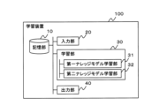
図1は、本発明による学習装置の一実施形態の構成例を示すブロック図である。本実施形態の学習装置100は、記憶部10と、入力部20と、学習部30と、出力部40とを備えている。
FIG. 1 is a block diagram showing a configuration example of an embodiment of a learning device according to the present invention. The
記憶部10は、本実施形態の学習装置100が処理に用いるパラメータや設定情報、ログデータなど、各種情報を記憶する。具体的には、記憶部10は、ある問題に対して正解したか否かを示す学習実績(以下、学習正誤ログと記す。)を記憶する。なお、学習正誤ログの内容は後述される。また、記憶部10は、後述する学習部30が生成した各モデルを記憶してもよい。
The
なお、学習装置100が、通信ネットワークを介して、他の装置(例えば、ストレージサーバ)から、各種情報を取得する構成であってもよい。この場合、記憶部10が上述する情報を記憶していなくてもよい。記憶部10は、例えば、磁気ディスク等により実現される。
Note that the
入力部20は、学習部30が処理に用いる各種情報の入力を受け付ける。入力部20は、例えば、記憶部10から各種情報を取得してもよいし、通信ネットワークを介して取得した各種情報の入力を受け付けてもよい。
The
また、本実施形態では、入力部20は、学習の実績を示す学習データとして、学習者の時系列の学習正誤ログの入力を受け付ける。具体的には、入力部20は、学習者の特徴を表わす情報(以下、ユーザ特徴と記すこともある。)に、問題とその問題の正誤とを対応付けたデータを含む学習データの入力を受け付ける。
Further, in the present embodiment, the
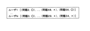
図2は、学習データの例を示す説明図である。図2に例示する学習データは、学習者であるユーザ1~ユーザNについて、各問題についての正誤(○,×)を対応付けたデータであることを示す。なお、各ユーザの特徴を示すユーザ特徴が、学習データとは別に保持されていてもよい。
FIG. 2 is an explanatory diagram showing an example of learning data. The learning data illustrated in FIG. 2 is data in which correctness (○, ×) of each question is associated with
学習部30は、第一ナレッジモデル学習部31と、第二ナレッジモデル学習部32とを含む。
The
第一ナレッジモデル学習部31は、学習者の学習実績を用いた機械学習により、学習者のスキルの状態の時系列変化(以下、スキル状態列と記す。)を生成する。学習者のスキルの状態は、例えば、学習者のスキルの習熟度である。
The first knowledge
学習実績からスキル状態列を生成できれば、その学習方法は任意である。第一ナレッジモデル学習部31は、例えば、非特許文献2に記載された方法を用いて、スキル状態列を生成してもよい。具体的には、第一ナレッジモデル学習部31は、学習正誤ログが与えられたもとでの事後確率が最大になる状態をスキル状態列として生成してもよい。
As long as a skill status sequence can be generated from learning results, the learning method is arbitrary. The first knowledge
また、第一ナレッジモデル学習部31は、学習に用いられた問題の特徴(以下、問題特徴ベクトルと記す。)を生成してもよい。第一ナレッジモデル学習部31は、スキル状態列の生成と同様、非特許文献2に記載された方法を用いて問題特徴ベクトルを生成してもよい。
The first knowledge
なお、問題特徴ベクトルは、学習実績に依らずとも生成することが可能である。例えば、非特許文献1に記載されているように、問題iについてのベクトルとして、i番目のエントリが1、その他のエントリが0のベクトルとして問題特徴ベクトルを生成できる。この問題特徴ベクトルは、各問題を識別するいわゆるone-hotベクトル([0,…,1,…,0])である。このように問題特徴ベクトル生成できる場合、第一ナレッジモデル学習部31は、問題特徴ベクトルを生成しなくてもよい。
Note that the problem feature vector can be generated without relying on learning results. For example, as described in
以下、非特許文献2に記載された方法を用いた場合のスキル状態列、および、問題特徴ベクトルについて、具体的に説明する。
Hereinafter, the skill state sequence and problem feature vector when using the method described in
本実施形態のスキル状態列は、非特許文献2に記載された非補償型時系列IRT(item response theory)の生成モデルにおける状態遷移確率(および初期状態確率)に対応する。そこで、第一ナレッジモデル学習部31は、以下の式1で定義されるモデルを学習することで、スキル状態列を生成してもよい。なお、式1は、時刻tにおけるユーザjの状態zj
(t)が与えられると、線形変換Dにより次の状態zj
(t+1)に遷移させるモデルである。なお、zj
(t)は、確率変数である。The skill state sequence of this embodiment corresponds to state transition probabilities (and initial state probabilities) in a generative model of uncompensated time series IRT (item response theory) described in

式1において、Di(j,t)は、ユーザjが時刻tに解いた問題iに応じて状態を変化させる線形変換を表わし、Γi(j,t+1)はガウスノイズを表わす。また、右辺の第二項はバイアス項であり、状態遷移に影響し得るユーザjの特徴量を表わす項である。In
具体的には、xj,k
(t+1)は、状態遷移の共変量であり、ユーザ特徴として、学習者に関する任意の特徴が用いられる。ユーザ特徴として、例えば、学習者の属性(例えば、年齢、性別)や、モチベーション(科目への興味の有無)、学習者jがスキルkを含む問題を最後に学習したときからの経過時間から想定される忘却率2^(-Δ/h)(ここで、Δは経過時間であり、hは半減期である)などが挙げられる。Specifically, x j,k (t+1) is a covariate of state transition, and any feature related to the learner is used as the user feature. User characteristics include, for example, the learner's attributes (e.g., age, gender), motivation (interest in the subject), and the amount of time that has passed since learner j last learned a problem that includes skill k. For example, the forgetting
また、他にも、ユーザ特徴として、実績系列の集計情報が用いられてもよい。集計情報として、例えば、各スキルについて連続5問正解までの回答数、習得の早さを示す情報、過去のテストの結果、などが挙げられる。 In addition, aggregate information of performance series may be used as the user characteristic. Examples of the aggregated information include the number of correct answers to five consecutive questions for each skill, information indicating the speed of learning, and the results of past tests.
また、βk Tは、スキルごとの特性を表わす係数であり、例えば、忘れやすいスキルの係数には、大きなマイナス値が設定される。また、μ0,P0は、学習者の初期状態のガウス分布の平均および分散をそれぞれ表わす。Further, β k T is a coefficient representing the characteristics of each skill, and for example, a large negative value is set as a coefficient for a skill that is easy to forget. Moreover, μ 0 and P 0 represent the mean and variance of the Gaussian distribution of the learner's initial state, respectively.
また、非特許文献2に記載された出力確率に含まれるaiおよびbiを含むベクトルは、本実施形態の問題特徴ベクトルに対応する。なお、aiは、問題iにおける各スキルの識別力(slope)を表すベクトルであり、biは、問題iの難易度である。そこで、第一ナレッジモデル学習部31は、以下の式2で定義されるモデルを学習することで、問題特徴ベクトルを生成してもよい。式2におけるQi(j,t),kは、問題iとスキルkの対応を示し、問題iを解くためにスキルkが必要であれば1になり、不要であれば0になる。Further, the vector including a i and b i included in the output probability described in

具体的には、第一ナレッジモデル学習部31は、問題特徴ベクトルを、以下に示す式3のように生成してもよい。例えば、問題1がスキル1およびスキル2を必要とする場合、第一ナレッジモデル学習部31は、下記の式3で示すベクトルについて、a1,a2,b1,b2以外を0にするような特徴ベクトルを生成すればよい。Specifically, the first knowledge

なお、非特許文献2に記載された方法を用いてスキル状態列および問題特徴ベクトルを生成する場合には、学習に際し、問題と必要なスキルとを対応付けた表(問題スキル対応表)を予め準備しておけばよい。図3は、問題と必要なスキルとを対応付けた例を示す説明図である。図3に示す例では、問題とその問題を解くために必要なスキルとを表形式で対応付けた例を示す。図3に例示するように、各問題で必要とされるスキルは1つであってもよく、2以上であってもよい。問題と必要なスキルの対応付けは、予めユーザ等により設定される。
Note that when generating skill state sequences and problem feature vectors using the method described in
このように、第一ナレッジモデル学習部31は、問題特徴ベクトルとして、問題の識別力および難易度を含むベクトル([…,ak,…,…,bk,…])を生成してもよい。In this way, the first knowledge
他にも、第一ナレッジモデル学習部31は、例えば、非特許文献1に記載された方法を用いて、スキル状態列を生成してもよい。本実施形態のスキル状態列は、非特許文献1に記載された時系列の予測確率のベクトルytに対応する。非特許文献1に記載されたytは、問題の数に等しい長さのベクトルであり、各エントリは、学習者が問題に正解する確率を表わす。このように、第一ナレッジモデル学習部31は、スキル状態列として時系列の予測確率のベクトルytを生成してもよい。Alternatively, the first knowledge
また、上述するように、非特許文献1に記載されたone-hotベクトルが、本実施形態の問題特徴ベクトルに対応する。具体的には、問題iについてのベクトルとして、i番目のエントリが1、その他のエントリが0のベクトルとして生成できる。このように、問題特徴ベクトルとして、各問題を識別するone-hotベクトル([0,…,1,…,0])が予め生成されていてもよい。この場合、第一ナレッジモデル学習部31は、問題特徴ベクトルを生成しなくてよい。
Further, as described above, the one-hot vector described in
以上、非特許文献1および非特許文献2に記載された方法を用いてスキル状態列および問題特徴ベクトルを生成する方法を説明した。ただし、スキル状態列および問題特徴ベクトルを生成する方法は、非特許文献1および非特許文献2に記載された学習方法に限定されない。
The method of generating a skill state sequence and problem feature vector using the methods described in
第二ナレッジモデル学習部32は、スキル状態列および問題特徴ベクトルを用いた機械学習により、学習者の将来のスキルの状態を予測するモデルを生成する。具体的には、第二ナレッジモデル学習部32は、問題特徴、ユーザ特徴、および、時間情報を説明変数とし、ユーザのスキル状態を目的変数とするモデルを学習する。
The second knowledge
スキル状態は、第一ナレッジモデル学習部31により生成されたスキル状態列から取得できる。また、問題特徴は、第一ナレッジモデル学習部31により生成された問題特徴ベクトルから取得されてもよく、問題に基づく任意の方法で生成された情報(例えば、one-hotベクトル)から取得されてもよい。ユーザ特徴は、第一ナレッジモデル学習部31が学習に用いる際のユーザ特徴と同様である。また、時間情報は、学習者が問題を解いた時間を表わす情報である。時間情報の態様は任意であり、例えば、YYYYMMDDHHMMの形式で表される時刻情報であってもよく、ある時刻t-1からtまでの経過時間などである。
The skill status can be acquired from the skill status sequence generated by the first knowledge
例えば、非特許文献2に記載された方法を用いた場合、第一ナレッジモデル学習部31は、スキル状態列として事後確率を最大にするスキル状態列を生成してもよい。具体的には、学習正誤ログが示すユーザjの実績yj
(1),…,yj
(Tj)の具体的な値が得られている状態で、第一ナレッジモデル学習部31は、以下に例示する事後確率を最大にするzj
(t)の値(状態変数)をt=1,…Tまで求めればよい。For example, when using the method described in

第二ナレッジモデル学習部32が学習するモデルの態様は任意であり、第二ナレッジモデル学習部32は、例えば、時系列データの予測で多く用いられるRNNを学習してもよい。また、RNNについて、一般的なRNNが用いられてもよく、LSTM(Long short-term memory)やGRU(Gated Recurrent Unit)などが用いられてもよい。
The mode of the model learned by the second knowledge
なお、ナレッジトレースを行うためのモデルの学習は、第一ナレッジモデル学習部31が行う学習のように、一般に、学習者の正誤データ(学習正誤ログ)を用いて行われる。一方、本実施形態の第二ナレッジモデル学習部32は、学習者の正誤データを直接用いずにナレッジトレースを行うモデルを学習していることから、第二ナレッジモデル学習部32が学習するモデルのことを、正誤データなしナレッジトレースモデルと言うことができる。
Note that learning of a model for performing knowledge tracing is generally performed using correct/incorrect data (learning correct/incorrect log) of the learner, as in the learning performed by the first knowledge
このように学習されたモデルを用いることで、ユーザ特徴で示される特徴を有する学習者が、ある時間において問題を選択した場合(解いた場合)のスキルの状態の変化を予測できる。これにより、例えば、学習者が主体的に作成した将来の学習計画について、その学習計画を実行した場合のスキルの状態の時系列変化を予測することが可能になる。 By using a model learned in this way, it is possible to predict a change in the state of a skill when a learner having the characteristics indicated by the user characteristics selects (solves) a problem at a certain time. This makes it possible, for example, to predict time-series changes in skill status when a learner executes a future learning plan that has been independently created by the learner.
出力部40は、第二ナレッジモデル学習部32が生成したモデル(正誤データなしナレッジトレースモデル)を出力する。出力部40は、生成されたモデルを記憶部10に記憶させてもよく、通信ネットワークを介して、他の記憶媒体(図示せず)に生成されたモデルを記憶させてもよい。
The
入力部20と、学習部30(より詳しくは、第一ナレッジモデル学習部31と、第二ナレッジモデル学習部32)と、出力部40とは、プログラム(学習プログラム)に従って動作するコンピュータのプロセッサ(例えば、CPU(Central Processing Unit )、GPU(Graphics Processing Unit))によって実現される。
The
例えば、プログラムは、記憶部10に記憶され、プロセッサは、そのプログラムを読み込み、プログラムに従って、入力部20、学習部30(より詳しくは、第一ナレッジモデル学習部31と、第二ナレッジモデル学習部32)および出力部40として動作してもよい。また入力部20、学習部30(より詳しくは、第一ナレッジモデル学習部31と、第二ナレッジモデル学習部32)および出力部40の機能がSaaS(Software as a Service )形式で提供されてもよい。
For example, the program is stored in the
また、入力部20と、学習部30(より詳しくは、第一ナレッジモデル学習部31と、第二ナレッジモデル学習部32)と、出力部40とは、それぞれが専用のハードウェアで実現されていてもよい。また、各装置の各構成要素の一部又は全部は、汎用または専用の回路(circuitry )、プロセッサ等やこれらの組合せによって実現されてもよい。これらは、単一のチップによって構成されてもよいし、バスを介して接続される複数のチップによって構成されてもよい。各装置の各構成要素の一部又は全部は、上述した回路等とプログラムとの組合せによって実現されてもよい。
Furthermore, the
また、入力部20、学習部30(より詳しくは、第一ナレッジモデル学習部31と、第二ナレッジモデル学習部32)および出力部40の各構成要素の一部又は全部が複数の情報処理装置や回路等により実現される場合には、複数の情報処理装置や回路等は、集中配置されてもよいし、分散配置されてもよい。例えば、情報処理装置や回路等は、クライアントサーバシステム、クラウドコンピューティングシステム等、各々が通信ネットワークを介して接続される形態として実現されてもよい。
In addition, some or all of the components of the
次に、本実施形態の学習装置100の動作を説明する。図4は、本実施形態の学習装置100の動作例を示すフローチャートである。学習部30(より詳しくは、第一ナレッジモデル学習部31)は、学習実績を用いた機械学習により、スキル状態列を生成する(ステップS11)。そして、学習部30(より詳しくは、第二ナレッジモデル学習部32)は、問題特徴、ユーザ特徴、および、時間情報を説明変数とし、学習者のスキルの状態を目的変数とするモデルを学習する(ステップS12)。
Next, the operation of the
以上のように、本実施形態では、第一ナレッジモデル学習部31が、学習実績を用いた機械学習により、スキル状態列を生成し、第二ナレッジモデル学習部32が、問題特徴、ユーザ特徴、および、時間情報を説明変数とし、学習者のスキルの状態を目的変数とするモデルを学習する。よって、学習者の長期的なスキルの変化を予測するモデルを学習できる。
As described above, in the present embodiment, the first knowledge
例えば、非特許文献2に記載されている方法では、学習者の時系列の学習正誤ログに基づいてナレッジトレーシングモデルを学習する。すなわち、非特許文献2に記載されたモデルは、問題を解いた正誤結果が学習データとして必要になるため、長期的予測に適したモデルにはなっていない。
For example, in the method described in
一方、本実施形態では、第二ナレッジモデル学習部32が、問題特徴、ユーザ特徴、および、時間情報を説明変数とし、学習者のスキルの状態を目的変数とするモデルを学習する。そのため、学習者の長期的な予測を行うことが可能になる。
On the other hand, in this embodiment, the second knowledge
実施形態2.
次に、本発明の第二の実施形態を説明する。第二の実施形態では、学習計画に基づく学習者のスキルの状態の変化を可視化する方法を説明する。なお、本実施形態における学習計画とは、学習者が、どの問題をいつどのような順序で解くかを表わす情報であり、学習者が解く予定の問題を時系列に並べた情報である。本実施形態では、どの問題をいつ解いたら、自身のスキルの状態がどのように変化するか可視化する方法について説明する。
Next, a second embodiment of the present invention will be described. In the second embodiment, a method for visualizing changes in a learner's skill status based on a learning plan will be described. Note that the learning plan in this embodiment is information indicating which questions the learner should solve, when and in what order, and is information in which the questions the learner is scheduled to solve are arranged in chronological order. In this embodiment, a method for visualizing how the state of one's skills changes depending on which problem and when is solved will be described.
以下の説明では、第一の実施形態で学習されたモデルを用いて、スキルの状態の変化を推定し、推定結果を可視化する方法を適宜説明する。ただし、スキルの状態の変化を推定する方法は、第一の実施形態で学習されたモデルを用いる方法に限定されない。 In the following description, a method for estimating a change in the state of a skill and visualizing the estimation result using the model learned in the first embodiment will be described as appropriate. However, the method for estimating the change in skill status is not limited to the method using the model learned in the first embodiment.
図5は、本発明による可視化システムの一実施形態の構成例を示すブロック図である。本実施形態の可視化システム1は、学習装置100と、可視化装置200とを備えている。本実施形態の学習装置100の内容は、第一の実施形態の学習装置100と同様であるため、詳細な説明を省略する。なお、第一の実施形態の学習装置100に含まれる記憶部10が、学習装置100とは別の装置に設けられていてもよい。
FIG. 5 is a block diagram showing a configuration example of an embodiment of the visualization system according to the present invention. The
可視化装置200は、学習装置100によって学習されたモデル(すなわち、正誤データなしナレッジトレースモデル)を取得する。なお、可視化装置200が処理に用いる情報(例えば、上記正誤データなしナレッジトレースモデルなど)が学習装置100とは別の装置に設けられた記憶装置(例えば記憶部10)に記憶されている場合、可視化装置200は、学習装置100に接続されていなくてもよい。
The
可視化装置200は、学習計画入力部210と、状態推定部220と、状態可視化部230とを含む。
The
学習計画入力部210は、学習計画の入力を受け付ける。学習計画入力部210は、例えば、表示装置(図示せず)に学習計画の入力画面を表示させ、学習者からインタラクティブに学習計画の入力を受け付けてもよい。図6は、学習計画を入力する画面の例を示す説明図である。学習計画入力部210は、図6に例示するようなカレンダー形式の入力画面211を表示し、適切な入力インタフェース(例えば、タッチパネル、ポインティングデバイス、キーボード等)を介して学習者により入力された学習計画を受け付けてもよい。
The learning
なお、表示装置は、可視化装置200に設けられていてもよく、通信回線を介して接続された可視化装置200とは異なる装置で実現されていてもよい。また、他にも、学習計画入力部210は、ファイル等に記載された学習計画の入力を受け付けてもよい。
Note that the display device may be provided in the
状態推定部220は、学習計画に基づき、スキルの状態の変化を推定する。具体的には、状態推定部220は、学習計画で設定された各問題を時系列に解いた場合における学習者のスキルの状態の変化を推定する。
The
スキルの状態の変化を推定する方法には、様々な方法を利用できる。例えば、問題を解いた場合に向上すると推定される各スキルの習熟度を予め定めておき、状態推定部220は、学習計画に従って、解いた問題に対応する習熟度を加味して(例えば、加算する、乗算する、など)スキルの状態の変化を推定してもよい。さらに、状態推定部220は、時間の経過に合わせて、スキルの習熟度を一定の関数(忘却曲線)に応じて減少させるようにしてもよい。
Various methods can be used to estimate changes in skill status. For example, the proficiency level of each skill that is estimated to improve when solving a problem is determined in advance, and the
また、より精度高くスキルの状態の変化を推定するため、状態推定部220は、第一の実施形態で学習されたモデル(正誤データなしナレッジトレースモデル)を用いて、スキルの状態の変化を推定してもよい。すなわち、状態推定部220は、学習者が学習に用いた問題の特徴を表わす問題特徴、学習者の特徴を表わすユーザ特徴、および、学習者が問題を解いた時間を表わす時間情報を説明変数とし、学習者のスキルの状態を目的変数とする予測モデルを用いて、スキルの状態の変化を推定してもよい。
Furthermore, in order to estimate changes in the skill state with higher accuracy, the
なお、第一の実施形態で示すように、上記予測モデルは、学習者による学習の実績を用いた機械学習により生成された、学習者のスキルの状態の時系列変化を表わすスキル状態列、および、学習者が学習に用いた問題の特徴を表わす問題特徴ベクトルに基づく特徴量を含むデータを用いて学習されたモデルである。 Note that, as shown in the first embodiment, the above-mentioned prediction model includes a skill state sequence representing time-series changes in the learner's skill state, which is generated by machine learning using the learner's learning results, and , is a model trained using data that includes features based on problem feature vectors that represent the characteristics of the problems that the learner used for learning.
状態可視化部230は、推定された学習者のスキルの状態を可視化する。図7は、スキルの状態を可視化した例を示す説明図である。図7に例示するように、横軸に時間を設定し、縦軸にスキルの状態(習熟度)を設定した折れ線グラフで、各時点における学習者のスキルの状態を時系列に可視化してもよい。
The
また、状態可視化部230は、指定された時点における学習者の正解確率を問題ごとに可視化してもよい。図8は、問題を解ける確率を可視化した例を示す説明図である。図8に示す例では、単元ごとにまとめられた各問題について、正解確率を棒グラフ311で可視化した例を示す。
Further, the
状態可視化部230は、例えば、正誤データなしナレッジトレースモデルを用いて、ある時点における学習者のスキルの状態を推定し、推定されたスキルに基づいて正解確率を算出してもよい。例えば、非特許文献2に記載された方法を用いる場合、状態可視化部230は、上記に示す式2を用いて、各問題の正解確率を算出し、算出結果を可視化してもよい。具体的には、状態可視化部230は、式2を用いて算出された正解確率の分布における平均を正解確率として棒グラフ311で可視化し、分散を不確定度合いとして線312で表わしてもよい。
The
また、状態可視化部230は、ある時点における学習者の各スキルの状態を、より詳細に可視化してもよい。状態可視化部230は、例えば、指定された時点において想定される学習者のスキルを、対象の問題を解くために必要とされるスキルごとに可視化してもよい。図9は、各スキルの状態をグラフで出力した例を示す説明図である。図9に例示するグラフは、ある問題を解くために必要とされるスキルごとに、学習者のスキルの状態を可視化したグラフである。また、図9に示す例では、例えば問題提供者によって、問題のレベルに応じた2種類のラベル付け(A-level,B-level)がされた状況を想定する。ラベル付けの具体例として、ラベル「A-level」が付与された問題(以下、A問題と記す。)が標準問題、ラベル「B-level」が付与された問題(以下、B問題と記す。)が発展問題、などが挙げられる。
Further, the
図9に示す例では、スキルの各レベルの閾値を境界線で示しており、境界線321が、A問題が全て解けると想定されるスキルの状態の閾値、境界線322が、B問題が全て解けると想定されるスキルの状態の閾値である。また、図9に示す例では、ある時点における各スキルの状態を棒グラフ323で表わし、そのスキルの状態の不確定度を丸付きの線324で表わしている。
In the example shown in FIG. 9, the threshold for each level of skill is shown by a boundary line, the
以下、上記非特許文献2に記載された非補償型の項目応答モデルを例に、図9に例示するスキルの状態を可視化する方法を説明する。初めに、図9に例示する境界線(すなわち、閾値)を特定する方法を説明する。
Hereinafter, a method for visualizing the skill state illustrated in FIG. 9 will be described using the non-compensated item response model described in
スキルをある問題に関連付ける場合、それらのスキルがすべて満たされることで解けるとすることが一般的である。非特許文献2に記載されたこのようなモデルは、多次元項目応答理論において非補償型モデルと呼ばれている。この非補償型モデルを用いた予測理由の説明は、自然であると言える。
When relating skills to a problem, it is common to assume that the problem can be solved if all of those skills are satisfied. Such a model described in
非補償型モデルでは、正解確率を予測するモデルが各スキルの積で表される。例えば、各スキルs1,s2の係数をそれぞれt1,t2とした場合、予測モデルは、シグモイド関数σを用いて、以下のように表すことができる。このような非補償型モデルでは、「分数と方程式の知識がなければ上記問題は解けない」と解釈されるため、説明性は高いと言える。In the non-compensated model, the model that predicts the probability of correct answer is expressed as the product of each skill. For example, if the coefficients of each skill s 1 and s 2 are t 1 and t 2 , the prediction model can be expressed as follows using a sigmoid function σ. Such a non-compensated model can be interpreted as ``the above problem cannot be solved without knowledge of fractions and equations,'' so it can be said to have high explanatory power.
正解確率=σ(t1s1)σ(t2s2)Probability of correct answer = σ(t 1 s 1 ) σ(t 2 s 2 )
また、学習者の状態zと問題iが与えられたときに、学習者がその問題iを解ける確率を表わすモデルは、例えば、上記式2を簡略化した以下に例示する式4で定義できる。すなわち、式4に例示するモデルは、問題iの解決に学習者が必要とするスキルkの組み合わせで表わされ、各スキルの積により問題を解ける確率が算出されるモデルである。学習者の状態zは、ある時点において学習者が有する各スキルkの習熟度を表わす。
Further, when a learner's state z and a problem i are given, a model representing the probability that the learner can solve the problem i can be defined, for example, by

式4において、上記式2と同様に、bi,kは、問題iで用いられるスキルkの難易度を表わし、ai,kは、問題iに関するスキルkの立ち上がりの程度(スロープ)を表わすパラメータである。すなわち、式4は、bi,kが示す難易度よりもスキルの習熟度zkが高ければ、高い確率で問題が解けることを表わす。In
図10は、正解確率の尤度関数の例を示す説明図である。図10に例示するグラフは、縦方向の軸(z軸)が正解確率を示し、その他の軸(x軸およびy軸)が、その問題を解くために必要なスキルの習熟度を表わす。具体的には、図10に例示する尤度関数は、上記に例示する式4で表される。例えば、図10に例示するように、ある問題を解くために2つのスキルが必要であったとする。この場合、一方のスキルだけが高くても正解確率は増加しないが、両方のスキルが高くなると正解確率が増加することを示す。
FIG. 10 is an explanatory diagram showing an example of a likelihood function of correct answer probability. In the graph illustrated in FIG. 10, the vertical axis (z-axis) indicates the probability of correct answer, and the other axes (x-axis and y-axis) indicate the proficiency level of the skill required to solve the problem. Specifically, the likelihood function illustrated in FIG. 10 is expressed by
例えば、図10に示す例において、あるレベル(例えば、A-level)の問題が全て解けるために管理者が正解確率=80%になるようなスキルの習熟度が必要であると想定したとする。この場合、尤度関数の値である正解確率の軸に対して垂直に、正解確率=0.8の位置で切断したときの断面が、スキルの習熟度の範囲を表わしていると言える。 For example, in the example shown in Figure 10, assume that in order to be able to solve all the problems at a certain level (for example, A-level), the administrator needs to have a level of proficiency in the skill that will give the probability of correct answer = 80%. . In this case, it can be said that the cross section taken perpendicularly to the axis of correct answer probability, which is the value of the likelihood function, at a position where correct answer probability = 0.8 represents the range of skill proficiency.
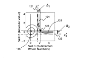
図11は、非補償型モデルの情報を模式的に表わす説明図である。図11に例示する情報は、例えば、分析エンジンの内部で非補償型モデルを扱う際の情報であり、対象とする問題に2つのスキル(「整数の減法」、「絶対値」)が必要であることを示す。また、ここでは、問題Aを解くためには正解確率=80%になるようなスキルの習熟度が必要であるとして指定された場合を想定する。 FIG. 11 is an explanatory diagram schematically representing information of a non-compensated model. The information illustrated in Figure 11 is, for example, information when handling a non-compensated model within the analysis engine, and the target problem requires two skills (``integer subtraction'' and ``absolute value''). Show that something is true. Further, here, a case is assumed where it is specified that in order to solve problem A, a skill proficiency level such that the probability of correct answer is 80% is required.
グラフの右上に斜線で示す領域111は、図10に例示する尤度関数において、正解確率=80%を満たすスキルの習熟度の範囲を示す。なお、「0.8」と記載されている曲線112が、正解確率=80%を満たすために必要なスキルの習熟度の境界を示す。また、グラフの左下に示す×印113が、現時点での学習者のスキルの状態を示す。また、×印113を取り囲む楕円114は、学習者のスキルの状態の分布がガウス分布に従うとした場合における確率の等高線を示す。この場合、学習者のスキルの状態の位置は、ガウス分布における平均に対応する。
A shaded
この想定に基づいて、状態可視化部230は、閾値を算出する。ここで算出される閾値は、図9に例示する境界線321が示す閾値に対応する。図12は、閾値を算出する処理の例を示す説明図である。まず、状態可視化部230は、各次元について座標zk
*を算出する。状態可視化部230は、例えば、上述する式4に基づき、以下に例示する式5を用いて、zk
*を算出する。Based on this assumption, the

なお、式5におけるpは正解確率を示し、aiおよびbiは、式4と同様、それぞれ、スロープおよび難易度を示す。なお、A問題がすべて解ける習熟度を想定することから、問題として、A問題のうち、最も難易度の高い問題iが選択されればよい。ここで算出されるzk
*は、図10に例示する尤度関数に、外側から接する面の座標に相当し、図12における長鎖線121および122に対応する。Note that p in Equation 5 represents the probability of correct answer, and a i and b i represent the slope and difficulty level, respectively, as in
次に、状態可視化部230は、境界線上の座標を変化させながら、Δ1=Δ2=…=ΔK(Kは、必要なスキルの数)に最も近づく座標z^(zの上付きハット)を探索する。なお、Δは、各次元について算出されたzk
*とz^との差分である。ここで算出されるz^は、図10に例示する尤度関数に内側から接する面の座標に相当し、図12における点123の座標に対応する。Next, while changing the coordinates on the boundary line, the
具体的には、状態可視化部230は、座標z^を算出するに際し、以下の2つの処理を繰り返す。まず、第1の処理として、状態可視化部230は、初期点として、zk={σ-1(p-k)/ai}+biを計算する。そして、状態可視化部230は、このzkに基づいて、各Δkの値を算出する。次に、状態可視化部230は、第2の処理として、最も大きいΔkについての次元kについて、以下の式6に示す更新を行う。なお、δは、パラメータであり、予め定められる。Specifically, the
zkmax←zkmax-δ (式6)z kmax ←z kmax −δ (Formula 6)
そして、状態可視化部230は、更新後のzkmaxをz´とし、最も小さいΔkについての次元kについて、以下の式7に示す更新を行う。状態可視化部230は、この2つの処理を、予め定めた条件(例えば、変化量が閾値未満、予め定めた回数、など)を満たすまで繰り返す。Then, the

次に、状態可視化部230は、各kについて、(z^
k-zk
*)/2を算出することで、領域を長方形近似する。ここで算出される値は、図12における破線124および125の座標に対応する。Next, the
そして、状態可視化部230は、学習者のスキルの習熟度と、長方形近似された座標が示す値との比率に基づいて、棒グラフを出力する。具体的には、状態可視化部230は、学習者のスキルの状態を示す座標126と、破線124および破線125が示す座標との比率に基づいて棒グラフを出力してもよい。このようにして、状態可視化部230は、対象の問題を解くために必要とされるスキルの習熟度(すなわち、閾値)と、学習者が有すると想定されるスキルの習熟度とを対応付けて出力する。問題Bの閾値についても同様である。
Then, the
さらに、状態可視化部230は、学習者のスキルの状態の不確定度を合わせて出力する。図13は、結果を可視化する処理の例を示す説明図である。例えば、スキル1(整数の減法)に対する学習者のスキルの状態がz1
2と推定されており、ガウス分布におけるスキルの状態の分散±σが、それぞれ、z1
1およびz1
3であるとする。そして、図12における破線124の座標がz1
4と算出されたとする。このとき、状態可視化部230は、学習者のスキル1の習熟度を、σ(ai,1(z1
2-bi,1))/σ(ai,1(z1
4-bi,1))で算出する。 Further, the
また、状態可視化部230は、ガウス分布で推定された学習者のスキルの状態を示す分布を用いて、そのガウス分布の分散を習熟度の不確定度として出力してもよい。具体的には、状態可視化部230は、不確定度の範囲を、σ(ai,1(z1
1-bi,1))/σ(ai,1(z1
4-bi,1))およびσ(ai,1(z1
3-bi,1))/σ(ai,1(z1
4-bi,1))で算出する。スキル2(絶対値)についても同様である。Further, the
このように、状態可視化部230は、閾値を1とした場合の、相対的なスキルの習熟度および不確定度を算出する。すなわち、状態可視化部230は、スキル名と関連付けて、閾値に対する現在の学習者のスキルの習熟度および不確定度を相対値で表現する。よって、学習者のスキルの過不足を、学習者が理解可能なスキル名に基づいて提示できる。さらに、状態可視化部230は、各スキルの不確定度を合わせて表現することで、学習者の納得感を向上させることも可能になる。
In this way, the
また、一般に、分析アルゴリズムによって出力される問題の難易度には単位がないため、難易度を示す値を見ただけでは、そのスキルの状態の程度を把握することが困難な場合がある。本実施形態では、状態可視化部230が、指定された時点において想定される学習者のスキルの習熟度と、対象とするグループ(例えば、ラベル付けされたグループ)に含まれる問題(例えば、A問題,B問題)を解くために必要とされるスキルの習熟度を示す閾値とを対応付けて可視化する。よって、問題提供者が指定するグループと、推定される難易度とが対応付けされるため、学習者のスキルの状況を把握しやすくなる。なお、グループ内の問題は1つであってもよく、複数であってもよい。
Furthermore, since there is generally no unit for the difficulty level of a problem output by an analysis algorithm, it may be difficult to grasp the level of the skill state just by looking at the value indicating the difficulty level. In this embodiment, the
さらに、状態可視化部230は、指定されたスキルを必要とする問題の候補を、「お勧め問題」として出力してもよい。具体的には、状態可視化部230は、指定されたスキルを必要とする問題の候補を、図3に例示するような問題とその問題を解くために必要なスキルとを対応付けた表から特定してもよい。
Furthermore, the
図14は、お勧め問題の出力例を示す説明図である。図14に示す例では、状態可視化部230が、「通分」のスキルについて、そのスキルを必要とする問題の候補(お勧め問題:Q13、Q18、Q31、Q33)を、そのスキルを必要とする程度(すなわち、習熟度、難易度)に応じて順序付けて、想定される学習者のスキルと対応付けて出力していることを示す。FIG. 14 is an explanatory diagram showing an output example of recommended questions. In the example shown in FIG. 14, the
また、図14に例示するように、状態可視化部230は、学習者がマウスなどのポインティングデバイスでお勧め問題の番号をマウスオーバーした際、その番号に対応する問題を出力してもよい。
Further, as illustrated in FIG. 14, when the learner hovers over the number of a recommended question using a pointing device such as a mouse, the
他にも、状態可視化部230は、不確定度を含むスキルの状態の変化を可視化してもよい。図15は、スキルの状態の変化を可視化した他の例を示す説明図である。状態可視化部230は、図15に例示するように、横軸に時間を設定し、縦軸にスキルの習熟度を設定した折れ線グラフで、不確定度の範囲331と共に、スキルの状態の変化を時系列に可視化してもよい。また、その際、状態可視化部230は、上記に示すようなラベル付けされた問題の境界線332を合わせて可視化してもよい。
In addition, the
また、状態可視化部230は、複数のスキルの状態の変化を可視化してもよい。図16は、スキルの状態の変化を可視化した更に他の例を示す説明図である。図16に示す例では、折れ線グラフ341で、複数のスキルの状態の推移をそれぞれ表わしている。また、学習実績との関係でスキルの推移を把握できるように、状態可視化部230は、図16に例示するように、各時点で解いた問題の正誤を棒グラフ342(例えば、正解なら上方向、不正解なら下方向)で可視化してもよい。
Further, the
学習計画入力部210と、状態推定部220と、状態可視化部230とは、プログラム(可視化プログラム)に従って動作するコンピュータのプロセッサによって実現される。例えば、プログラムは、可視化装置200が備える記憶部(図示せず)に記憶され、ロセッサは、そのプログラムを読み込み、プログラムに従って、学習計画入力部210、状態推定部220および状態可視化部230として動作してもよい。学習計画入力部210、状態推定部220および状態可視化部230の機能がSaaS形式で提供されてもよい。
The learning
また、学習計画入力部210と、状態推定部220と、状態可視化部230とは、それぞれが専用のハードウェアで実現されていてもよい。また、各装置の各構成要素の一部又は全部は、汎用または専用の回路(circuitry )、プロセッサ等やこれらの組合せによって実現されてもよい。これらは、単一のチップによって構成されてもよいし、バスを介して接続される複数のチップによって構成されてもよい。各装置の各構成要素の一部又は全部は、上述した回路等とプログラムとの組合せによって実現されてもよい。
Further, the learning
また、学習計画入力部210と、状態推定部220と、状態可視化部230の各構成要素の一部又は全部が複数の情報処理装置や回路等により実現される場合には、複数の情報処理装置や回路等は、集中配置されてもよいし、分散配置されてもよい。例えば、情報処理装置や回路等は、クライアントサーバシステム、クラウドコンピューティングシステム等、各々が通信ネットワークを介して接続される形態として実現されてもよい。
In addition, when some or all of the components of the learning
次に、本実施形態の可視化装置200の動作を説明する。図17は、本実施形態の可視化装置200の動作例を示すフローチャートである。学習計画入力部210は、学習計画の入力を受け付ける(ステップS21)。状態推定部220は、学習計画で設定された各問題を時系列に解いた場合の将来の各時点における学習者のスキルの状態を推定する(ステップS22)。そして、状態可視化部230は、推定された各時点における学習者のスキルの状態を可視化する(ステップS23)。なお、可視化の態様は、例えば、図7~図9、図13~図16に示す内容などである。
Next, the operation of the
以上のように、本実施形態では、学習計画入力部210が、学習計画の入力を受け付け、状態推定部220が、学習計画で設定された各問題を時系列に解いた場合の将来の各時点における学習者のスキルの状態を推定する。そして、状態可視化部230は、推定された各時点における学習者のスキルの状態を可視化する。よって、学習者の長期的なスキルの変化を可視化できる。
As described above, in this embodiment, the learning
次に、本発明の概要を説明する。図18は、本発明によるスキル可視化装置の概要を示すブロック図である。本発明によるスキル可視化装置90(例えば、可視化装置200)は、学習者が解く予定の問題を時系列に並べた情報である学習計画の入力を受け付ける学習計画入力部91(例えば、学習計画入力部210)と、学習計画で予定された各問題を時系列に解いた場合の将来の各時点における学習者のスキルの状態を推定する状態推定部92(例えば、状態推定部220)と、推定された各時点における学習者のスキルの状態を可視化する状態可視化部93(例えば、状態可視化部230)とを備えている。 Next, an overview of the present invention will be explained. FIG. 18 is a block diagram showing an overview of the skill visualization device according to the present invention. The skill visualization device 90 (for example, the visualization device 200) according to the present invention includes a learning plan input unit 91 (for example, a learning plan input unit 210), a state estimator 92 (e.g., state estimator 220) that estimates the state of the learner's skill at each point in the future when each problem scheduled in the learning plan is solved in chronological order; The state visualization unit 93 (for example, the state visualization unit 230) that visualizes the state of the learner's skill at each point in time is provided.
そのような構成により、長期的なスキルの変化を可視化できる。 Such a configuration allows for visualization of long-term skill changes.
また、状態可視化部93は、指定された時点において想定される学習者のスキルを、対象の問題を解くために必要とされるスキルごとに可視化してもよい(例えば、図9に例示するグラフ)。
Further, the
具体的には、状態可視化部93は、指定された時点において想定される学習者のスキルの習熟度(例えば、図9に例示する棒グラフ323)と、対象の問題を解くために必要とされるスキルの習熟度を示す閾値(例えば、図9に例示する境界線322)とを対応付けて可視化してもよい。
Specifically, the
さらに、このとき、状態可視化部93は、指定された時点において想定される学習者のスキルの習熟度と、対象とするグループ(例えば、ラベル「A-level」が付与された問題のグループ)に含まれる問題(例えば、A問題)を解くために必要とされるスキルの習熟度を示す閾値とを対応付けて可視化してもよい(例えば、図9に例示するグラフ)。そのような構成により、問題提供者が指定するグループと、推定される難易度とが対応付けされるため、学習者のスキルの状況を把握しやすくなる。
Furthermore, at this time, the
また、状態可視化部93は、1以上のスキルの状態の変化を時系列に可視化してもよい(例えば、図7、図15、図16に例示するグラフ)。
Further, the
また、状態可視化部93は、指定された時点における正解確率を問題ごとに可視化してもよい(例えば、図8に例示するグラフ)。
Further, the
また、状態可視化部93は、指定されたスキルを必要とする問題の候補を、そのスキルを必要とする程度に応じて順序付けて、想定される学習者のスキルと対応付けて出力してもよい(例えば、図14に例示する「お勧め問題」)。
Further, the
ここで、状態推定部92は、学習者が学習に用いた問題の特徴を表わす問題特徴、その学習者の特徴を表わすユーザ特徴、および、その学習者が問題を解いた時間を表わす時間情報を説明変数とし、学習者のスキルの状態を目的変数とする予測モデル(例えば、「正誤データなしナレッジトレースモデル」)を用いて、スキルの状態の変化を推定してもよい。
Here, the
具体的には、予測モデルは、学習者による学習の実績を用いた機械学習により生成される、学習者のスキルの状態の時系列変化を表わすスキル状態列、および、学習者が前記学習に用いた問題の特徴を表わす問題特徴ベクトルに基づく特徴量を含むデータを用いて(例えば、学習装置100により)学習されてもよい。 Specifically, the prediction model includes a skill state sequence representing time-series changes in the learner's skill state, which is generated by machine learning using the learner's learning performance, and a skill state sequence that represents the time-series changes in the learner's skill state. Learning may be performed (for example, by the learning device 100) using data including feature amounts based on a problem feature vector representing the characteristics of the problem.
図19は、少なくとも1つの実施形態に係るコンピュータの構成を示す概略ブロック図である。コンピュータ1000は、プロセッサ1001、主記憶装置1002、補助記憶装置1003、インタフェース1004を備える。
FIG. 19 is a schematic block diagram showing the configuration of a computer according to at least one embodiment. The
上述のスキル可視化装置90は、コンピュータ1000に実装される。そして、上述した各処理部の動作は、プログラム(スキル可視化プログラム)の形式で補助記憶装置1003に記憶されている。プロセッサ1001は、プログラムを補助記憶装置1003から読み出して主記憶装置1002に展開し、当該プログラムに従って上記処理を実行する。
The
なお、少なくとも1つの実施形態において、補助記憶装置1003は、一時的でない有形の媒体の一例である。一時的でない有形の媒体の他の例としては、インタフェース1004を介して接続される磁気ディスク、光磁気ディスク、CD-ROM(Compact Disc Read-only memory )、DVD-ROM(Read-only memory)、半導体メモリ等が挙げられる。また、このプログラムが通信回線によってコンピュータ1000に配信される場合、配信を受けたコンピュータ1000が当該プログラムを主記憶装置1002に展開し、上記処理を実行してもよい。
Note that in at least one embodiment,
また、当該プログラムは、前述した機能の一部を実現するためのものであっても良い。さらに、当該プログラムは、前述した機能を補助記憶装置1003に既に記憶されている他のプログラムとの組み合わせで実現するもの、いわゆる差分ファイル(差分プログラム)であってもよい。
Moreover, the program may be for realizing part of the functions described above. Furthermore, the program may be a so-called difference file (difference program) that implements the above-described functions in combination with other programs already stored in the
上記の実施形態の一部又は全部は、以下の付記のようにも記載されうるが、以下には限られない。 Part or all of the above embodiments may be described as in the following additional notes, but are not limited to the following.
(付記1)学習者が解く予定の問題を時系列に並べた情報である学習計画の入力を受け付ける学習計画入力部と、前記学習計画で予定された各問題を時系列に解いた場合の将来の各時点における学習者のスキルの状態を推定する状態推定部と、推定された前記各時点における学習者のスキルの状態を可視化する状態可視化部とを備えたことを特徴とするスキル可視化装置。 (Additional Note 1) A learning plan input section that accepts input of a learning plan, which is information in which the problems that the learner plans to solve are arranged in chronological order, and the future when each problem planned in the learning plan is solved in chronological order. A skill visualization device comprising: a state estimation unit that estimates the state of a learner's skill at each time point; and a state visualization unit that visualizes the estimated skill state of the learner at each time point.
(付記2)状態可視化部は、指定された時点において想定される学習者のスキルを、対象の問題を解くために必要とされるスキルごとに可視化する付記1記載のスキル可視化装置。
(Supplementary note 2) The skill visualization device according to
(付記3)状態可視化部は、指定された時点において想定される学習者のスキルの習熟度と、対象の問題を解くために必要とされるスキルの習熟度を示す閾値とを対応付けて可視化する付記1または付記2記載のスキル可視化装置。
(Additional note 3) The state visualization unit visualizes the expected skill proficiency level of the learner at a specified time in association with a threshold value indicating the skill proficiency level required to solve the target problem. The skill visualization device according to
(付記4)状態可視化部は、指定された時点において想定される学習者のスキルの習熟度と、対象とするグループに含まれる問題を解くために必要とされるスキルの習熟度を示す閾値とを対応付けて可視化する付記1から付記3のうちのいずれか1つに記載のスキル可視化装置。
(Additional note 4) The state visualization unit sets a threshold value indicating the expected skill proficiency level of the learner at a specified time and the skill proficiency level required to solve the problems included in the target group. The skill visualization device according to any one of
(付記5)状態可視化部は、1以上のスキルの状態の変化を時系列に可視化する付記1から付記4のうちのいずれか1つに記載のスキル可視化装置。
(Supplementary Note 5) The skill visualization device according to any one of
(付記6)状態可視化部は、指定された時点における正解確率を問題ごとに可視化する付記1から付記5のうちのいずれか1つに記載のスキル可視化装置。
(Supplementary Note 6) The skill visualization device according to any one of
(付記7)状態可視化部は、指定されたスキルを必要とする問題の候補を、当該スキルを必要とする程度に応じて順序付けて、想定される学習者のスキルと対応付けて出力する付記1から付記6のうちのいずれか1つに記載のスキル可視化装置。
(Additional note 7) The state visualization unit outputs candidates for questions that require a specified skill, in order according to the degree to which the skill is required, and in correspondence with the assumed learner's skill. The skill visualization device according to any one of
(付記8)状態推定部は、学習者が学習に用いた問題の特徴を表わす問題特徴、当該学習者の特徴を表わすユーザ特徴、および、当該学習者が前記問題を解いた時間を表わす時間情報を説明変数とし、学習者のスキルの状態を目的変数とする予測モデルを用いて、スキルの状態の変化を推定する付記1から付記7のうちのいずれか1項に記載のスキル可視化装置。
(Additional Note 8) The state estimating unit uses problem features representing the characteristics of the problems used by the learner for learning, user characteristics representing the characteristics of the learner, and time information representing the time at which the learner solved the problem. The skill visualization device according to any one of
(付記9)予測モデルは、学習者による学習の実績を用いた機械学習により生成される、学習者のスキルの状態の時系列変化を表わすスキル状態列、および、学習者が前記学習に用いた問題の特徴を表わす問題特徴ベクトルに基づく特徴量を含むデータを用いて学習される付記8記載のスキル可視化装置。
(Additional note 9) The prediction model consists of a skill status sequence representing time-series changes in the learner's skill status, which is generated by machine learning using the learner's learning results, and a skill status sequence that represents the time-series changes in the learner's skill status, and The skill visualization device according to
(付記10)学習者が解く予定の問題を時系列に並べた情報である学習計画の入力を受け付け、前記学習計画で予定された各問題を時系列に解いた場合の将来の各時点における学習者のスキルの状態を推定し、推定された前記各時点における学習者のスキルの状態を可視化することを特徴とするスキル可視化方法。 (Additional note 10) Learning at each point in the future when input of a learning plan, which is information in which the problems the learner plans to solve are arranged in chronological order, is received, and each problem planned in the learning plan is solved in chronological order. A skill visualization method comprising: estimating a learner's skill state and visualizing the estimated skill state of the learner at each of the points in time.
(付記11)指定された時点において想定される学習者のスキルを、対象の問題を解くために必要とされるスキルごとに可視化する付記10記載のスキル可視化方法。
(Supplementary note 11) The skill visualization method according to
(付記12)コンピュータに、学習者が解く予定の問題を時系列に並べた情報である学習計画の入力を受け付ける学習計画入力処理、前記学習計画で予定された各問題を時系列に解いた場合の将来の各時点における学習者のスキルの状態を推定する状態推定処理、および、推定された前記各時点における学習者のスキルの状態を可視化する状態可視化処理を実行させるためのスキル可視化プログラムを記憶するプログラム記憶媒体。 (Additional Note 12) A learning plan input process in which the computer receives input of a learning plan, which is information in which the problems the learner plans to solve are arranged in chronological order, and when each problem planned in the learning plan is solved in chronological order. Stores a skill visualization program for executing state estimation processing for estimating the state of the learner's skills at each future point in time, and state visualization processing for visualizing the estimated state of the learner's skills at each of the estimated points in time. program storage medium.
(付記13)コンピュータに、状態可視化処理で、指定された時点において想定される学習者のスキルを、対象の問題を解くために必要とされるスキルごとに可視化させるためのスキル可視化プログラムを記憶する付記12記載のプログラム記憶媒体。
(Additional Note 13) A skill visualization program is stored in the computer that allows the computer to visualize the skills of the learner expected at a specified time, for each skill required to solve the target problem, through state visualization processing. The program storage medium according to
(付記14)コンピュータに、学習者が解く予定の問題を時系列に並べた情報である学習計画の入力を受け付ける学習計画入力処理、前記学習計画で予定された各問題を時系列に解いた場合の将来の各時点における学習者のスキルの状態を推定する状態推定処理、および、推定された前記各時点における学習者のスキルの状態を可視化する状態可視化処理を実行させるためのスキル可視化プログラム。 (Additional note 14) A learning plan input process in which the computer receives input of a learning plan, which is information in which the problems that the learner plans to solve are arranged in chronological order, and when each problem planned in the learning plan is solved in chronological order. A skill visualization program for executing a state estimation process for estimating the state of a learner's skills at each future point in time, and a state visualization process for visualizing the estimated skill state of the learner at each of the estimated times.
(付記15)コンピュータに、状態可視化処理で、指定された時点において想定される学習者のスキルを、対象の問題を解くために必要とされるスキルごとに可視化させる付記14記載のスキル可視化プログラム。
(Supplementary note 15) The skill visualization program according to
以上、実施形態を参照して本願発明を説明したが、本願発明は上記実施形態に限定されるものではない。本願発明の構成や詳細には、本願発明のスコープ内で当業者が理解し得る様々な変更をすることができる。 Although the present invention has been described above with reference to the embodiments, the present invention is not limited to the above embodiments. The configuration and details of the present invention can be modified in various ways that can be understood by those skilled in the art within the scope of the present invention.
1 可視化システム
10 記憶部
20 入力部
30 学習部
31 第一ナレッジモデル学習部
32 第二ナレッジモデル学習部
40 出力部
100 学習装置
200 可視化装置
210 学習計画入力部
220 状態推定部
230 状態可視化部1
Claims (10)
前記学習計画で予定された各問題を時系列に解いた場合の将来の各時点における学習者のスキルの状態を推定する状態推定部と、
推定された前記各時点における学習者のスキルの状態を可視化する状態可視化部とを備えた
ことを特徴とするスキル可視化装置。 a learning plan input unit that receives input of a learning plan, which is information in which problems that a learner plans to solve are arranged in chronological order;
a state estimation unit that estimates the state of the learner's skills at each future point in time when each problem scheduled in the learning plan is solved in chronological order;
A skill visualization device comprising: a state visualization unit that visualizes the estimated skill state of the learner at each of the time points.
請求項1記載のスキル可視化装置。 The skill visualization device according to claim 1, wherein the state visualization unit visualizes the skills of the learner expected at a specified time for each skill required to solve the target problem.
請求項1または請求項2記載のスキル可視化装置。 Claim 1: The state visualization unit associates and visualizes the learner's skill proficiency level assumed at a specified time and a threshold value indicating the skill proficiency level required to solve the target problem. Or the skill visualization device according to claim 2.
請求項1から請求項3のうちのいずれか1項に記載のスキル可視化装置。 The state visualization unit associates the expected skill proficiency level of the learner at a specified time with a threshold value indicating the skill proficiency level required to solve the problems included in the target group. The skill visualization device according to any one of claims 1 to 3.
請求項1から請求項4のうちのいずれか1項に記載のスキル可視化装置。 The skill visualization device according to any one of claims 1 to 4, wherein the state visualization unit visualizes changes in the state of one or more skills in chronological order.
請求項1から請求項5のうちのいずれか1項に記載のスキル可視化装置。 The skill visualization device according to any one of claims 1 to 5, wherein the state visualization unit visualizes the correct answer probability for each question at a specified time point.
請求項1から請求項6のうちのいずれか1項に記載のスキル可視化装置。 The state visualization unit outputs the candidates for questions that require the specified skill, in order according to the degree to which the skill is required, and in association with the skills of the assumed learner. 6. The skill visualization device according to any one of 6.
請求項1から請求項7のうちのいずれか1項に記載のスキル可視化装置。 The state estimation unit uses problem features representing the characteristics of the problems used by the learner for learning, user characteristics representing the characteristics of the learner, and time information representing the time the learner solved the problem as explanatory variables. The skill visualization device according to any one of claims 1 to 7, wherein a change in skill status is estimated using a predictive model that uses the learner's skill status as an objective variable.
前記学習計画で予定された各問題を時系列に解いた場合の将来の各時点における学習者のスキルの状態を推定し、
推定された前記各時点における学習者のスキルの状態を可視化する
ことを特徴とするスキル可視化方法。 Accepts the input of a learning plan, which is information in which the problems that the learner plans to solve are arranged in chronological order.
Estimate the state of the learner's skills at each future point in time when each problem scheduled in the learning plan is solved in chronological order,
A skill visualization method, comprising: visualizing the estimated state of the learner's skill at each of the time points.
学習者が解く予定の問題を時系列に並べた情報である学習計画の入力を受け付ける学習計画入力処理、
前記学習計画で予定された各問題を時系列に解いた場合の将来の各時点における学習者のスキルの状態を推定する状態推定処理、および、
推定された前記各時点における学習者のスキルの状態を可視化する状態可視化処理
を実行させるためのスキル可視化プログラム。 to the computer,
learning plan input processing that accepts input of a learning plan, which is information in which problems that a learner plans to solve are arranged in chronological order;
a state estimation process for estimating the state of the learner's skills at each future point in time when each problem scheduled in the learning plan is solved in chronological order;
A skill visualization program for executing a state visualization process for visualizing the estimated skill state of a learner at each of the above-mentioned points.
Applications Claiming Priority (1)
| Application Number | Priority Date | Filing Date | Title |
|---|---|---|---|
| PCT/JP2020/020927 WO2021240685A1 (en) | 2020-05-27 | 2020-05-27 | Skill visualization apparatus, skill visualization method, and skill visualization program |
Publications (3)
| Publication Number | Publication Date |
|---|---|
| JPWO2021240685A1 JPWO2021240685A1 (en) | 2021-12-02 |
| JPWO2021240685A5 JPWO2021240685A5 (en) | 2023-01-30 |
| JP7355240B2 true JP7355240B2 (en) | 2023-10-03 |
Family
ID=78723109
Family Applications (1)
| Application Number | Title | Priority Date | Filing Date |
|---|---|---|---|
| JP2022527356A Active JP7355240B2 (en) | 2020-05-27 | 2020-05-27 | Skill visualization device, skill visualization method, and skill visualization program |
Country Status (3)
| Country | Link |
|---|---|
| US (1) | US20230138245A1 (en) |
| JP (1) | JP7355240B2 (en) |
| WO (1) | WO2021240685A1 (en) |
Families Citing this family (1)
| Publication number | Priority date | Publication date | Assignee | Title |
|---|---|---|---|---|
| KR20230114127A (en) * | 2022-01-24 | 2023-08-01 | 비트루브 주식회사 | Method, system and non-transitory computer-readable recording medium for providing information on user's conceptual understanding |
Citations (3)
| Publication number | Priority date | Publication date | Assignee | Title |
|---|---|---|---|---|
| US20120077158A1 (en) | 2010-09-28 | 2012-03-29 | Government Of The United States, As Represented By The Secretary Of The Air Force | Predictive Performance Optimizer |
| US20130266922A1 (en) | 2010-01-15 | 2013-10-10 | Apollo Group, Inc. | Recommending Competitive Learning Objects |
| JP2014178449A (en) | 2013-03-14 | 2014-09-25 | Nec Fielding Ltd | Education support device, education support system, education support method and program |
Family Cites Families (6)
| Publication number | Priority date | Publication date | Assignee | Title |
|---|---|---|---|---|
| US20090075246A1 (en) * | 2007-09-18 | 2009-03-19 | The Learning Chameleon, Inc. | System and method for quantifying student's scientific problem solving efficiency and effectiveness |
| US8777628B2 (en) * | 2010-09-28 | 2014-07-15 | The United States Of America As Represented By The Secretary Of The Air Force | Predictive performance optimizer |
| US20140065590A1 (en) * | 2012-02-20 | 2014-03-06 | Knowre Korea Inc | Method, system, and computer-readable recording medium for providing education service based on knowledge units |
| US20150050637A1 (en) * | 2013-08-16 | 2015-02-19 | Big Brothers Big Sisters of Eastern Missouri | System and method for early warning and recognition for student achievement in schools |
| US20150170536A1 (en) * | 2013-12-18 | 2015-06-18 | William Marsh Rice University | Time-Varying Learning and Content Analytics Via Sparse Factor Analysis |
| WO2017077383A1 (en) * | 2015-11-04 | 2017-05-11 | EDUCATION4SIGHT GmbH | Systems and methods for instrumentation of education processes |
-
2020
- 2020-05-27 JP JP2022527356A patent/JP7355240B2/en active Active
- 2020-05-27 US US17/926,652 patent/US20230138245A1/en active Pending
- 2020-05-27 WO PCT/JP2020/020927 patent/WO2021240685A1/en active Application Filing
Patent Citations (3)
| Publication number | Priority date | Publication date | Assignee | Title |
|---|---|---|---|---|
| US20130266922A1 (en) | 2010-01-15 | 2013-10-10 | Apollo Group, Inc. | Recommending Competitive Learning Objects |
| US20120077158A1 (en) | 2010-09-28 | 2012-03-29 | Government Of The United States, As Represented By The Secretary Of The Air Force | Predictive Performance Optimizer |
| JP2014178449A (en) | 2013-03-14 | 2014-09-25 | Nec Fielding Ltd | Education support device, education support system, education support method and program |
Also Published As
| Publication number | Publication date |
|---|---|
| WO2021240685A1 (en) | 2021-12-02 |
| JPWO2021240685A1 (en) | 2021-12-02 |
| US20230138245A1 (en) | 2023-05-04 |
Similar Documents
| Publication | Publication Date | Title |
|---|---|---|
| US10546507B2 (en) | Recommending a set of learning activities based on dynamic learning goal adaptation | |
| Govindarajan et al. | Dynamic learning path prediction—A learning analytics solution | |
| JP7253324B2 (en) | Causal relationship learning device, causal relationship estimating device, causal relationship learning method, causal relationship estimating method and program | |
| KR102075743B1 (en) | Apparatus and method for body growth prediction modeling | |
| JP7355240B2 (en) | Skill visualization device, skill visualization method, and skill visualization program | |
| JP7355239B2 (en) | Learning devices, learning methods and learning programs | |
| CN114298299A (en) | Model training method, device, equipment and storage medium based on course learning | |
| WO2020235631A1 (en) | Model generation device, system, parameter calculation device, model generation method, parameter calculation method, and recording medium | |
| JP7409481B2 (en) | Skill output device, skill output method, and skill output program | |
| Islam et al. | Pakes: a reinforcement learning-based personalized adaptability knowledge extraction strategy for adaptive learning systems | |
| US20220335309A1 (en) | Knowledge tracing device, method, and program | |
| Dai et al. | An improved deep model for knowledge tracing and question-difficulty discovery | |
| JP7063397B2 (en) | Answer integration device, answer integration method and answer integration program | |
| JP6832410B1 (en) | Learning effect estimation device, learning effect estimation method, program | |
| JP2022068690A (en) | Decision-making supporting device | |
| Wachowiak-Smolíková et al. | Data Analytics and Visualization of Adaptive Collaboration Simulations | |
| Dharmawan et al. | Machine Learning Implementation for Profit Estimation | |
| US20230041545A1 (en) | Storage medium, explanatory information output method, and information processing device | |
| JP7147874B2 (en) | LEARNING DEVICE, LEARNING METHOD AND LEARNING PROGRAM | |
| Rashid et al. | Machine learning and software quality prediction: as an expert system | |
| KR102635769B1 (en) | Learning effect estimation device, learning effect estimation method, program | |
| US20220076162A1 (en) | Storage medium, data presentation method, and information processing device | |
| WO2020235625A1 (en) | Model generation device, parameter calculation device, model generation method, parameter calculation method, and recording medium | |
| Brown et al. | Visualisation of fuzzy decision support information: A case study | |
| McKenna | An Investigation of Knowledge Tracing Algorithms as Learner Simulators |
Legal Events
| Date | Code | Title | Description |
|---|---|---|---|
| A521 | Request for written amendment filed |
Free format text: JAPANESE INTERMEDIATE CODE: A523 Effective date: 20221111 |
|
| A621 | Written request for application examination |
Free format text: JAPANESE INTERMEDIATE CODE: A621 Effective date: 20221111 |
|
| TRDD | Decision of grant or rejection written | ||
| A01 | Written decision to grant a patent or to grant a registration (utility model) |
Free format text: JAPANESE INTERMEDIATE CODE: A01 Effective date: 20230822 |
|
| A61 | First payment of annual fees (during grant procedure) |
Free format text: JAPANESE INTERMEDIATE CODE: A61 Effective date: 20230904 |
|
| R151 | Written notification of patent or utility model registration |
Ref document number: 7355240 Country of ref document: JP Free format text: JAPANESE INTERMEDIATE CODE: R151 |