JP7354886B2 - connector device - Google Patents
connector device Download PDFInfo
- Publication number
- JP7354886B2 JP7354886B2 JP2020044402A JP2020044402A JP7354886B2 JP 7354886 B2 JP7354886 B2 JP 7354886B2 JP 2020044402 A JP2020044402 A JP 2020044402A JP 2020044402 A JP2020044402 A JP 2020044402A JP 7354886 B2 JP7354886 B2 JP 7354886B2
- Authority
- JP
- Japan
- Prior art keywords
- movable
- terminal
- terminal portion
- outer conductor
- connecting member
- Prior art date
- Legal status (The legal status is an assumption and is not a legal conclusion. Google has not performed a legal analysis and makes no representation as to the accuracy of the status listed.)
- Active
Links
Images


Classifications
-
- H—ELECTRICITY
- H01—ELECTRIC ELEMENTS
- H01R—ELECTRICALLY-CONDUCTIVE CONNECTIONS; STRUCTURAL ASSOCIATIONS OF A PLURALITY OF MUTUALLY-INSULATED ELECTRICAL CONNECTING ELEMENTS; COUPLING DEVICES; CURRENT COLLECTORS
- H01R12/00—Structural associations of a plurality of mutually-insulated electrical connecting elements, specially adapted for printed circuits, e.g. printed circuit boards [PCB], flat or ribbon cables, or like generally planar structures, e.g. terminal strips, terminal blocks; Coupling devices specially adapted for printed circuits, flat or ribbon cables, or like generally planar structures; Terminals specially adapted for contact with, or insertion into, printed circuits, flat or ribbon cables, or like generally planar structures
- H01R12/70—Coupling devices
- H01R12/91—Coupling devices allowing relative movement between coupling parts, e.g. floating or self aligning
-
- H—ELECTRICITY
- H01—ELECTRIC ELEMENTS
- H01R—ELECTRICALLY-CONDUCTIVE CONNECTIONS; STRUCTURAL ASSOCIATIONS OF A PLURALITY OF MUTUALLY-INSULATED ELECTRICAL CONNECTING ELEMENTS; COUPLING DEVICES; CURRENT COLLECTORS
- H01R13/00—Details of coupling devices of the kinds covered by groups H01R12/70 or H01R24/00 - H01R33/00
- H01R13/62—Means for facilitating engagement or disengagement of coupling parts or for holding them in engagement
- H01R13/629—Additional means for facilitating engagement or disengagement of coupling parts, e.g. aligning or guiding means, levers, gas pressure electrical locking indicators, manufacturing tolerances
- H01R13/631—Additional means for facilitating engagement or disengagement of coupling parts, e.g. aligning or guiding means, levers, gas pressure electrical locking indicators, manufacturing tolerances for engagement only
-
- H—ELECTRICITY
- H01—ELECTRIC ELEMENTS
- H01R—ELECTRICALLY-CONDUCTIVE CONNECTIONS; STRUCTURAL ASSOCIATIONS OF A PLURALITY OF MUTUALLY-INSULATED ELECTRICAL CONNECTING ELEMENTS; COUPLING DEVICES; CURRENT COLLECTORS
- H01R13/00—Details of coupling devices of the kinds covered by groups H01R12/70 or H01R24/00 - H01R33/00
- H01R13/648—Protective earth or shield arrangements on coupling devices, e.g. anti-static shielding
- H01R13/658—High frequency shielding arrangements, e.g. against EMI [Electro-Magnetic Interference] or EMP [Electro-Magnetic Pulse]
- H01R13/6581—Shield structure
- H01R13/6585—Shielding material individually surrounding or interposed between mutually spaced contacts
- H01R13/6588—Shielding material individually surrounding or interposed between mutually spaced contacts with through openings for individual contacts
-
- H—ELECTRICITY
- H01—ELECTRIC ELEMENTS
- H01R—ELECTRICALLY-CONDUCTIVE CONNECTIONS; STRUCTURAL ASSOCIATIONS OF A PLURALITY OF MUTUALLY-INSULATED ELECTRICAL CONNECTING ELEMENTS; COUPLING DEVICES; CURRENT COLLECTORS
- H01R24/00—Two-part coupling devices, or either of their cooperating parts, characterised by their overall structure
- H01R24/38—Two-part coupling devices, or either of their cooperating parts, characterised by their overall structure having concentrically or coaxially arranged contacts
- H01R24/40—Two-part coupling devices, or either of their cooperating parts, characterised by their overall structure having concentrically or coaxially arranged contacts specially adapted for high frequency
- H01R24/50—Two-part coupling devices, or either of their cooperating parts, characterised by their overall structure having concentrically or coaxially arranged contacts specially adapted for high frequency mounted on a PCB [Printed Circuit Board]
-
- H—ELECTRICITY
- H01—ELECTRIC ELEMENTS
- H01R—ELECTRICALLY-CONDUCTIVE CONNECTIONS; STRUCTURAL ASSOCIATIONS OF A PLURALITY OF MUTUALLY-INSULATED ELECTRICAL CONNECTING ELEMENTS; COUPLING DEVICES; CURRENT COLLECTORS
- H01R12/00—Structural associations of a plurality of mutually-insulated electrical connecting elements, specially adapted for printed circuits, e.g. printed circuit boards [PCB], flat or ribbon cables, or like generally planar structures, e.g. terminal strips, terminal blocks; Coupling devices specially adapted for printed circuits, flat or ribbon cables, or like generally planar structures; Terminals specially adapted for contact with, or insertion into, printed circuits, flat or ribbon cables, or like generally planar structures
- H01R12/70—Coupling devices
- H01R12/71—Coupling devices for rigid printing circuits or like structures
- H01R12/72—Coupling devices for rigid printing circuits or like structures coupling with the edge of the rigid printed circuits or like structures
- H01R12/73—Coupling devices for rigid printing circuits or like structures coupling with the edge of the rigid printed circuits or like structures connecting to other rigid printed circuits or like structures
-
- H—ELECTRICITY
- H01—ELECTRIC ELEMENTS
- H01R—ELECTRICALLY-CONDUCTIVE CONNECTIONS; STRUCTURAL ASSOCIATIONS OF A PLURALITY OF MUTUALLY-INSULATED ELECTRICAL CONNECTING ELEMENTS; COUPLING DEVICES; CURRENT COLLECTORS
- H01R13/00—Details of coupling devices of the kinds covered by groups H01R12/70 or H01R24/00 - H01R33/00
- H01R13/648—Protective earth or shield arrangements on coupling devices, e.g. anti-static shielding
- H01R13/658—High frequency shielding arrangements, e.g. against EMI [Electro-Magnetic Interference] or EMP [Electro-Magnetic Pulse]
- H01R13/6591—Specific features or arrangements of connection of shield to conductive members
- H01R13/6596—Specific features or arrangements of connection of shield to conductive members the conductive member being a metal grounding panel
-
- H—ELECTRICITY
- H01—ELECTRIC ELEMENTS
- H01R—ELECTRICALLY-CONDUCTIVE CONNECTIONS; STRUCTURAL ASSOCIATIONS OF A PLURALITY OF MUTUALLY-INSULATED ELECTRICAL CONNECTING ELEMENTS; COUPLING DEVICES; CURRENT COLLECTORS
- H01R2103/00—Two poles
-
- H—ELECTRICITY
- H01—ELECTRIC ELEMENTS
- H01R—ELECTRICALLY-CONDUCTIVE CONNECTIONS; STRUCTURAL ASSOCIATIONS OF A PLURALITY OF MUTUALLY-INSULATED ELECTRICAL CONNECTING ELEMENTS; COUPLING DEVICES; CURRENT COLLECTORS
- H01R24/00—Two-part coupling devices, or either of their cooperating parts, characterised by their overall structure
- H01R24/38—Two-part coupling devices, or either of their cooperating parts, characterised by their overall structure having concentrically or coaxially arranged contacts
- H01R24/40—Two-part coupling devices, or either of their cooperating parts, characterised by their overall structure having concentrically or coaxially arranged contacts specially adapted for high frequency
- H01R24/54—Intermediate parts, e.g. adapters, splitters or elbows
- H01R24/542—Adapters
Description
本開示は、コネクタ装置に関するものである。 The present disclosure relates to connector devices.
特許文献1には、互いに対向する第1コネクタと第2コネクタを有し、両コネクタをアダプターを介して接続するコネクタ装置が開示されている。第1コネクタと第2コネクタが対向方向と交差する方向へ位置ずれしても、アダプターが傾くことにより両コネクタの位置ずれが吸収される。第1コネクタは、第1内導体を包囲する第1外導体を有し、第2コネクタは、第2内導体を包囲する第2外導体を有する。アダプターは、可動内導体を包囲する可動外導体を有する。第1外導体と第2外導体は、可動外導体を介して導通した状態でアース回路に接続される。
第1コネクタと第2コネクタをアダプターを介して接続する上記の接続構造を、多極のコネクタ装置に適用した場合、次のような問題が懸念される。コネクタ装置の小型化を図ろうとした場合、アダプター同士の間隔が狭まる。そのため、隣り合う可動外導体の間で電位差が生じた場合、アース性能が低下することが懸念される。 When the above connection structure in which the first connector and the second connector are connected via an adapter is applied to a multi-pole connector device, the following problems may arise. When attempting to downsize the connector device, the distance between the adapters becomes narrower. Therefore, if a potential difference occurs between adjacent movable outer conductors, there is a concern that the grounding performance will deteriorate.
本開示のコネクタ装置は、上記のような事情に基づいて完成されたものであって、アース性能を向上させることを目的とする。 The connector device of the present disclosure was completed based on the above circumstances, and aims to improve grounding performance.
本開示のコネクタ装置は、
第1回路基板に実装される複数の第1端子部と、第2回路基板に実装される複数の第2端子部と、複数の可動端子部とを備え、
前記第1端子部は、第1内導体を包囲する第1外導体を有し、
前記第2端子部は、第2内導体を包囲する第2外導体を有し、
前記可動端子部は、可動内導体を包囲する可動外導体を有し、
前記可動端子部は、前記第2端子部を支点として揺動可能であり、
前記可動端子部の先端部は、前記第1端子部に対して接続可能であり、
前記複数の可動外導体は、接続部材を介して導通可能に接続されている。
The connector device of the present disclosure includes:
comprising a plurality of first terminal parts mounted on a first circuit board, a plurality of second terminal parts mounted on a second circuit board, and a plurality of movable terminal parts,
The first terminal portion has a first outer conductor surrounding a first inner conductor,
The second terminal portion has a second outer conductor surrounding a second inner conductor,
The movable terminal portion has a movable outer conductor surrounding a movable inner conductor,
The movable terminal part is swingable about the second terminal part as a fulcrum,
The distal end portion of the movable terminal portion is connectable to the first terminal portion,
The plurality of movable outer conductors are electrically connected via a connecting member.
本開示のコネクタ装置によれば、アース性能に優れている。 According to the connector device of the present disclosure, the grounding performance is excellent.
[本開示の実施形態の説明]
最初に本開示の実施形態を列記して説明する。
[Description of embodiments of the present disclosure]
First, embodiments of the present disclosure will be listed and described.
本開示のコネクタ装置は、
(1)第1回路基板に実装される複数の第1端子部と、第2回路基板に実装される複数の第2端子部と、複数の可動端子部とを備え、前記第1端子部は、第1内導体を包囲する第1外導体を有し、前記第2端子部は、第2内導体を包囲する第2外導体を有し、前記可動端子部は、可動内導体を包囲する可動外導体を有し、前記可動端子部は、前記第2端子部を支点として揺動可能であり、前記可動端子部の先端部は、前記第1端子部に対して接続可能であり、前記複数の可動外導体は、接続部材を介して導通可能に接続されている。本開示の構成によれば、複数の可動外導体同士が接続部材を介して導通されているので、複数の可動外導体の間で電位差が生じることがない。したがって、アース性能に優れている。
The connector device of the present disclosure includes:
(1) A plurality of first terminal parts mounted on a first circuit board, a plurality of second terminal parts mounted on a second circuit board, and a plurality of movable terminal parts, the first terminal part being , the movable terminal portion has a first outer conductor surrounding the first inner conductor, the second terminal portion has a second outer conductor surrounding the second inner conductor, and the movable terminal portion surrounds the movable inner conductor. It has a movable outer conductor, the movable terminal part is swingable about the second terminal part, a tip part of the movable terminal part is connectable to the first terminal part, The plurality of movable outer conductors are electrically connected via a connecting member. According to the configuration of the present disclosure, since the plurality of movable outer conductors are electrically connected to each other via the connecting member, a potential difference does not occur between the plurality of movable outer conductors. Therefore, it has excellent earthing performance.
(2)前記接続部材は、前記可動外導体に対して弾性接触する弾性接触片を有していることが好ましい。この構成によれば、接続部材と可動外導体を確実に接触させることができる。 (2) Preferably, the connecting member has an elastic contact piece that makes elastic contact with the movable outer conductor. According to this configuration, the connecting member and the movable outer conductor can be brought into reliable contact.
(3)前記弾性接触片は、前記可動外導体の外周に沿って延びた形状であることが好ましい。この構成によれば、可動端子部が径方向へ変位したときに、弾性接触片が可動端子部の動きに柔軟に追従するので、接続部材と可動外導体との接触状態が安定する。 (3) It is preferable that the elastic contact piece has a shape extending along the outer periphery of the movable outer conductor. According to this configuration, when the movable terminal section is displaced in the radial direction, the elastic contact piece flexibly follows the movement of the movable terminal section, so that the contact state between the connecting member and the movable outer conductor is stabilized.
(4)前記接続部材は、前記複数の可動端子部を個別に貫通させる孔部を有していることが好ましい。この構成によれば、可動端子部がいずれの方向へ揺動した場合でも、可動端子部が接続部材から離脱するおそれはない。 (4) It is preferable that the connection member has a hole through which the plurality of movable terminal parts are individually penetrated. According to this configuration, even when the movable terminal section swings in any direction, there is no possibility that the movable terminal section will separate from the connection member.
(5)前記接続部材は、非破断面において前記可動外導体に接触する当接部を有していることが好ましい。この構成によれば、接続部材の破断面によって可動外導体が傷付けられることを防止できる。 (5) It is preferable that the connection member has a contact portion that contacts the movable outer conductor on an unbroken surface. According to this configuration, it is possible to prevent the movable outer conductor from being damaged by the broken surface of the connecting member.
(6)前記複数の第2端子部はハウジングに保持されており、前記接続部材と前記ハウジングは、前記接続部材を前記ハウジングに取り付けた状態に保持する保持部を有していることが好ましい。この構成によれば、接続部材とハウジングを一体化させておくことができるので、取り扱いが容易となる。 (6) It is preferable that the plurality of second terminal parts are held by a housing, and that the connection member and the housing have a holding part that holds the connection member in a state where it is attached to the housing. According to this configuration, since the connecting member and the housing can be integrated, handling becomes easy.
(7)(6)において、前記接続部材側の前記保持部と前記ハウジング側の前記保持部は、前記可動端子部の揺動時における前記接続部材の変位方向と交差する方向に対向する対向面を有し、前記接続部材が変位を許容された範囲内にあるときに、前記接続部材側の前記対向面と前記ハウジング側の前記対向面が対向した位置関係を保つことが好ましい。この構成によれば、可動端子部が揺動するときに、保持部を弾性変形させなくても、接続部材を変位させることができる。 (7) In (6), the holding part on the connecting member side and the holding part on the housing side have opposing surfaces facing in a direction intersecting a displacement direction of the connecting member when the movable terminal part swings. It is preferable that the connecting member has a positional relationship in which the opposing surface on the connecting member side and the opposing surface on the housing side face each other when the connecting member is within a permitted displacement range. According to this configuration, when the movable terminal section swings, the connecting member can be displaced without elastically deforming the holding section.
(8)(1)において、前記複数の第2外導体がハウジングに固定され、前記複数の可動外導体が、前記複数の第2外導体に対して個別に導通可能に接触しており、前記接続部材が、前記複数の前記第2外導体と導通可能に接触していることが好ましい。この構成によれば、接続部材の接触対象である第2外導体は、ハウジングに固定されているので、接続部材と第2外導体との接触信頼性が高い。これにより、複数の第2外導体同士の間での電位差がなくなるので、複数の可動外導体を確実に同電位に保持することができる。 (8) In (1), the plurality of second outer conductors are fixed to the housing, the plurality of movable outer conductors are individually electrically connected to the plurality of second outer conductors, and the Preferably, the connecting member is in conductive contact with the plurality of second outer conductors. According to this configuration, since the second outer conductor that is the object of contact of the connection member is fixed to the housing, the contact reliability between the connection member and the second outer conductor is high. This eliminates the potential difference between the plurality of second outer conductors, so that the plurality of movable outer conductors can be reliably held at the same potential.
(9)(1)において、前記複数の可動外導体が、前記複数の第2外導体に対して個別に導通可能に接触しており、前記複数の第2外導体が、前記接続部材を介して一体化された単一部品であることが好ましい。この構成によれば、複数の第2外導体が単一部品を構成しているので、第2外導体間で電位差が生じることがなく、複数の可動外導体を確実に同電位に保持することができる。 (9) In (1), the plurality of movable outer conductors are individually electrically connected to the plurality of second outer conductors, and the plurality of second outer conductors are connected via the connection member. Preferably, it is a single integrated part. According to this configuration, since the plurality of second outer conductors constitute a single component, a potential difference does not occur between the second outer conductors, and the plurality of movable outer conductors can be reliably held at the same potential. I can do it.
[本開示の実施形態の詳細]
[実施例1]
本開示のコネクタ装置Aを具体化した実施例1を、図1~図8を参照して説明する。なお、本発明はこれらの例示に限定されるものではなく、特許請求の範囲によって示され、特許請求の範囲と均等の意味および範囲内でのすべての変更が含まれることが意図される。本実施例1において、前後の方向については、図1~3における斜め右下方向方を前方と定義する。上下の方向については、図1~6,8にあらわれる向きを、そのまま上方、下方と定義する。左右の方向については、図1~3における斜め左下方向を、左方と定義する。
[Details of embodiments of the present disclosure]
[Example 1]
A first embodiment embodying the connector device A of the present disclosure will be described with reference to FIGS. 1 to 8. Note that the present invention is not limited to these examples, but is indicated by the scope of the claims, and is intended to include all changes within the meaning and scope equivalent to the scope of the claims. In the first embodiment, regarding the front-back direction, the diagonally lower right direction in FIGS. 1 to 3 is defined as the front. Regarding the vertical direction, the directions appearing in FIGS. 1 to 6 and 8 are directly defined as upward and downward. Regarding the left and right directions, the diagonally lower left direction in FIGS. 1 to 3 is defined as the left direction.
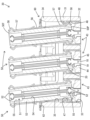
本実施例1のコネクタ装置Aは、図8に示すように、第1回路基板Bに実装される第1コネクタ10と、第2回路基板Cに実装される第2コネクタ30とを有している。第1回路基板Bは、例えば、自動車の屋根(図示省略)に取り付けられるシャークフィンアンテナ(図示省略)に設けられるものである。第1回路基板Bは、実装面を下向き、つまり車内側に向けた状態で水平に配置される。第2回路基板Cは、例えば、自動車の屋根に取り付けられたECUに設けられるものであり、実装面を上向き、つまりシャークフィンアンテナ側に向けた状態で水平に配置される。第1回路基板Bと第2回路基板Cは、双方の実装面同士を平行に対向させた位置関係で配置される。
As shown in FIG. 8, the connector device A of the first embodiment includes a
第1コネクタ10と第2コネクタ30は、第1回路基板Bを第2回路基板Cに接近させることによって導通可能に嵌合される。両コネクタ10,30が嵌合することにより、第1回路基板Bと第2回路基板Cがワイヤーハーネスを介さずに接続され、第1回路基板Bと第2回路基板Cとの間で高速通信が可能となる。自動車の屋根におけるシャークフィンアンテナの取付部分では、屋根とシャークフィンアンテナとの間の組付け公差が比較的大きいため、両コネクタ10,30の嵌合方向と交差する水平方向において、第1回路基板Bと第2回路基板Cとの間で位置ずれが生じ得る。本実施例1のコネクタ装置Aは、両回路基板B,Cの位置ずれを吸収しながら両コネクタ10,30の嵌合を行えるようになっている。
The
第1コネクタ10は、図8に示すように、第1ハウジング11と、複数の第1端子部16とを備えている。第1コネクタ10を第1回路基板Bに実装した状態では、第1ハウジング11の上面が第1回路基板Bに固定され、複数の第1端子部16の上端部が第1回路基板Bのプリント回路(図示省略)に接続される。第1ハウジング11は、直方形の第1端子保持部12と方形の誘導部14とを有する合成樹脂製の単一部品である。第1端子保持部12には、第1端子保持部12を上下に貫通した形態の複数の第1端子収容室13が形成されている。第1コネクタ10を上から見た平面視において、第1端子収容室13は円形をなす。複数の第1端子収容室13は、前後方向及び左右方向に整列するように配置されている。
The
誘導部14は、第1端子保持部12の下端における外周縁から斜め下方へスカート状に突出した形態である。誘導部14は、両コネクタ10,30の嵌合方向に対し、下方に向かって裾広がりとなるように傾斜している。誘導部14は、第1端子保持部12の全周に亘って連続している。平面視において、誘導部14は、複数の第1端子収容室13の全てを包囲している。第1ハウジング11内のうち、第1端子保持部12よりも下方において誘導部14により区画された空間は、第1揺動空間15として機能する。第1揺動空間15は、第1ハウジング11の下方へ開放されている。
The
複数の第1端子収容室13内には、複数の第1端子部16が個別に収容されている。図8に示すように、第1端子部16は、金属製の第1内導体17と、合成樹脂製の第1誘電体21と、金属製の第1外導体22とを備えている。第1内導体17は、軸線を両コネクタ10,30の嵌合方向と平行に向けた筒形をなす。第1内導体17は、小径部18と、小径部18の外周から径方向に突出した爪部19と、小径部18よりも径寸法の大きい大径部20とを有する。小径部18と大径部20は軸線方向に連なっている。第1誘電体21は、中心孔を有する円盤形をなす。第1外導体22は、軸線を第1内導体17及び第1誘電体21と平行に向けた円筒形をなす。
A plurality of first
第1端子部16は、第1内導体17の小径部18を第1誘電体21で同軸状に包囲し、第1内導体17と第1誘電体21を第1外導体22で同軸状に包囲した形態である。第1誘電体21は第1外導体22の上端部に位置する。第1外導体22内のうち第1誘電体21よりも下方の空間は、下方へ開放された接続空間23として機能する。接続空間23内においては、第1内導体17の大径部20が下向きに突出している。各接続空間23は第1揺動空間15と連通している。
The first
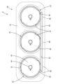
図2に示すように、第2コネクタ30は、第2ハウジング31と、第1端子部16と同数の複数の第2端子部43と、第2端子部43と同数の複数の可動端子部50とを備えている。第2コネクタ30を第2回路基板Cに実装した状態では、第2ハウジング31の下面が第2回路基板Cに固定され、複数の第2端子部43の下端部が第2回路基板Cのプリント回路(図示省略)に接続される。第2ハウジング31は、直方形の第2端子保持部32と、方形の周壁部34と、左右対称な一対の保持突起40とを有する合成樹脂製の単一部品である。
As shown in FIG. 2, the
第2端子保持部32には、第2端子部43と同数の複数の第2端子収容室33が形成されている。第2端子収容室33は、第2端子保持部32を上下に貫通した形態である。第2コネクタ30を上から見た平面視において、第2端子収容室33は円形をなす。複数の第2端子収容室33は、複数の第1端子収容室13と同じく、前後方向及び左右方向に整列するように配置されている。
A plurality of second
図2に示すように、周壁部34は、第2端子保持部32の上端における外周縁から、両コネクタ10,30の嵌合方向と平行に上方へ突出した形態である。平面視において、周壁部34は、複数の第2端子収容室33の全てを包囲している。第2ハウジング31のうち、第2端子保持部32よりも上方において周壁部34により区画された空間は、第2揺動空間35として機能する。第2揺動空間35は、第2ハウジング31の上方、即ち第1コネクタ10側へ開放されている。周壁部34を構成する左右両側壁部36には、切欠部37が形成されている。切欠部37は、側壁部36の上端縁から下方へ略方形に切り欠いた形態である。
As shown in FIG. 2, the
両側壁部36には、切欠部37を左右方向外方から覆う形態の支持壁部38が形成されている。支持壁部38の前後両端部は、屈曲形状をなしていて側壁部36の外側面に連なっている。支持壁部38によって区画された空間は、切欠部37を介して第2揺動空間35と連通した保持空間39として機能する。左右両支持壁部38の内側面には、保持突起40が形成されている。保持突起40は、支持壁部38の前後方向中央部から保持空間39内に突出している。図6に示すように、保持突起40の上面には、支持壁部38側から第2揺動空間35側に向かって下るように傾斜したガイド斜面41が形成されている。保持突起40の下面は、両コネクタ10,30の嵌合方向と交差する固定側対向面42として機能する。
図5に示すように、複数の第2端子収容室33内には、複数の第2端子部43が個別に収容されている。図6に示すように、第2端子部43は、金属製の第2内導体44と、合成樹脂製の第2誘電体45と、金属製の第2外導体46とを備えている。第2内導体44は、第1内導体17と同一の部品であり、小径部18と爪部19と大径部20とを有する。第2内導体44は、軸線方向において第1内導体17とは逆向きに配置されている。第2誘電体45は、第1誘電体21と同一の部品であり、軸線方向において第1誘電とは逆向きに配置されている。第2外導体46は、軸線を第2内導体44及び第2誘電体45と平行に向けた円筒形をなす。
As shown in FIG. 5 , a plurality of second
第2端子部43は、第2内導体44の小径部18を第2誘電体45で同軸状に包囲し、第2内導体44と第2誘電体45を第2外導体46で同軸状に包囲した形態である。第2誘電体45は第2外導体46の下端部に位置する。第2外導体46内のうち第2誘電体45よりも上方の空間は、上方へ開放された支持空間47として機能する。支持空間47内においては、第2内導体44の大径部20が上向きに突出している。各支持空間47は第2揺動空間35と連通している。第2外導体46の上端部内周には、全周に亘って連続した縮径部48が形成されている。縮径部48は、支持空間47内に配置され、径方向内側へ膨らむような形状である。
The
図2,5に示すように、可動端子部50は、全体として細長い形状をなす。可動端子部50は、軸線方向両端部を反転させたときに同一の形状となる対称性を有している。図5に示すように、可動端子部50は、金属製の可動内導体51と、合成樹脂製の可動誘電体53と、金属製の可動外導体56とを備えて構成された部材である。可動内導体51の軸線方向両端部には、それぞれ、径方向へ弾性変形可能な一対の弾性爪片52が形成されている。
As shown in FIGS. 2 and 5, the
可動誘電体53は、合成樹脂製であり、可動端子部50の軸線と同軸状の円筒形をなす。可動誘電体53の中心部には、可動誘電体53を同軸状に貫通した形態の挿通孔54が形成されている。可動誘電体53の軸線方向両端部には、可動誘電体53の両端面を同軸状に凹ませた形態の円形の収容凹部55が形成されている。収容凹部55は、挿通孔54の軸線方向両端部を構成する空間である。収容凹部55の内径は挿通孔54の内径よりも大きい。
The movable
可動外導体56は、全体として円筒形をなす。図2,5に示すように、可動外導体56の軸線方向両端部には、周方向に間隔を空けて配された複数の弾性アーム部57が形成されている。弾性アーム部57は、軸線方向端部側へ片持ち状に延出した形態であり、径方向へ弾性変形することが可能である。弾性アーム部57の延出端部には、拡径部58が形成されている。
The movable
可動端子部50は、可動誘電体53の挿通孔54内に可動内導体51を挿通し、可動誘電体53の外周に可動外導体56を嵌合した形態である。可動内導体51の弾性爪片52は、収容凹部55内に位置する。図6に示すように、可動誘電体53の軸線方向両端部の外周と、可動外導体56の弾性アーム部57の内周との間には、弾性アーム部57の弾性変形を許容する撓み空間59が確保されている。
The
可動端子部50の一方の端部は、可動端子部50の基端部50Pとして第2端子部43に取り付けられている。取り付けに際しては、可動端子部50の基端部50Pを第2コネクタ30の支持空間47内に挿入する。可動端子部50を第2端子部43に取り付けた状態では、収容凹部55内に第2内導体44の大径部20が収容され、可動内導体51の弾性爪片52が、第2内導体44の大径部20の内周に対し弾性的に接触する。可動外導体56の弾性アーム部57が弾性変形し、拡径部58が、第2外導体46の内周に対し弾性的に接触する。
One end portion of the
可動外導体56の拡径部58が第2外導体46の縮径部48に係止することにより、可動端子部50が第2端子部43から離脱することを規制される。可動端子部50が第2端子部43から下方へ突出するように上下反転させた向きにしても、拡径部58と縮径部48との係止状態が保たれる。可動端子部50は、基端部50Pと第2端子部43との接触部分を支点として、個別に揺動することが可能である。可動端子部50が第2端子部43に対して前後方向又は左右方向へ揺動しても、拡径部58と縮径部48との係止状態が保たれる。
By engaging the
第2端子部43に取り付けた可動端子部50は、第2ハウジング31から上方へ突出した形態である。可動端子部50の他方の端部、即ち上端部は、可動端子部50の先端部50Tとして、第1端子部16と接続するようになっている。ここで、1つの可動端子部50は1つの第2端子部43のみに接触した状態で支持されているので、複数の可動端子部50は、他の可動端子部50とは異なる方向へ個別に揺動し得るようになっている。しかし、複数の可動端子部50が互いに異なる方向へ揺動した状態では、第1コネクタ10と第2コネクタ30を嵌合するときに、複数の可動端子部50の先端部50Tを、複数の第1端子部16に対して同時に接続させることができない。
The
その対策として、第2コネクタ30には、アライメント部材60が設けられている。アライメント部材60は、プレス加工により所定形状に打ち抜いた金属製の板材に、曲げ加工を施して成形された単一部品である。図3に示すように、アライメント部材60は、板状本体部61と、左右対称な一対の弾性保持片68とを有する。板状本体部61は、板厚方向を両コネクタ10,30の嵌合方向と平行に向けた平板状をなす。板状本体部61は、平面視において第2ハウジング31の周壁部34と同じ形状をなしている。
As a countermeasure against this, the
板状本体部61には、平面視において複数の第2端子部43と同じ配置の複数の孔部62が形成されている。孔部62は、可動外導体56の外径よりも内径寸法の大きい円形をなし、板状本体部61を上下方向に貫通した形態である。孔部62の内周には、周方向に間隔を空けた複数の固定突起部63が形成されている。固定突起部63は、孔部62の内周から径方向中心側へ延出した延出部の先端部を、下側へ折り返するように密着曲げして形成されている。
A plurality of
固定突起部63の突出端部の外周面は、半円弧形の曲面状をなす固定当接部64として機能する。固定当接部64の全領域は、アライメント部材60の表面のうちプレス加工によって生じる破断面とは異なる非破断面のみによって構成されている。複数の固定突起部63の突出端、即ち複数の固定当接部64に内接する内接円の直径寸法は、可動外導体56の外径と同じ寸法か、それよりも僅かに大きい寸法である。
The outer peripheral surface of the protruding end of the fixed
板状本体部61には、板状本体部61の上面に重なるように配された複数の弾性接触片65が一体に形成されている。弾性接触片65の平面視形状は円弧形をなす。1つの弾性接触片65は、板状本体部61の外周縁を基点とし、1つの孔部62の開口縁に沿って片持ち状に延出した形態である。弾性接触片65の延出端部には、可動突起部66が形成されている。可動突起部66は、弾性接触片65の延出端部の内周から径方向中心側へ延出した延出部の先端部を、上側へ折り返するように密着曲げして形成されている。可動突起部66の突出端部の外周面は、半円弧形の曲面状をなす可動当接部67として機能する。可動当接部67の全領域は、固定当接部64と同様、非破断面のみによって構成されている。
A plurality of
図3に示すように、弾性保持片68は、板状本体部61の側縁から板状本体部61と直角に下方へ延出した前後一対の脚部69と、両脚部69の延出端同士を連結する係止部70とを有する。係止部70は、板状本体部61と平行な板状をなす。図3,7に示すように、係止部70の上面は、可動側対向面71となっている。可動側対向面71は、固定側対向面42に対し両コネクタ10,30の嵌合方向と平行な上下方向に対向するようになっている。弾性保持片68には、係止部70の内側の側縁から斜め下方へ張り出した被ガイド部72が形成されている。
As shown in FIG. 3, the
アライメント部材60は、第2ハウジング31に対し上方から接近させることによって、第2ハウジング31に取り付けられている。取り付ける過程では、一対の被ガイド部72が一対のガイド斜面41に摺接することにより、一対の弾性保持片68が互いに接近する方向、つまり第2揺動空間35側へ変位するように弾性変形する。被ガイド部72と係止部70が保持突起40を通過すると、一対の弾性保持片68は、互いに離間するように弾性復帰して、保持空間39内に収容される。弾性保持片68の可動側対向面71は、第2ハウジング31の固定側対向面42に対し下から対向する。以上により、第2ハウジング31に対するアライメント部材60の組付けが完了する。
The
第2ハウジング31にアライメント部材60を取り付けた状態では、板状本体部61の外周縁部が周壁部34の上端面に載置され、脚部69と係止部70が保持空間39内に収容され、係止部70が保持突起40の下側に潜り込む。係止部70が保持突起40に係止することにより、アライメント部材60は第2ハウジング31からの離脱を規制される。板状本体部61の外周縁が周壁部34と整合する状態では、脚部69と支持壁部38との間及び係止部70と支持壁部38との間にクリアランスが確保されている。
When the
したがって、アライメント部材60は、第2ハウジング31に対し、板状本体部61と平行な方向への相対変位を許容された状態に保持される。板状本体部61と平行な方向は、両コネクタ10,30の嵌合方向と直角に交差する方向であり、両回路基板B,Cの位置ずれが想定される方向である。第2ハウジング31に対するアライメント部材60の相対変位量は、脚部69又は係止部70が支持壁部38に当接したときが最大となる。アライメント部材60の相対変位量が最大になった状態では、可動側対向面71の少なくとも一部が、固定側対向面42の少なくとも一部に対し上下方向に対向する状態を保つ。したがって、アライメント部材60の変位量が最大であっても、アライメント部材60は第2ハウジング31に取り付けられた状態に保持される。
Therefore, the
アライメント部材60を第2ハウジング31に取り付けた後、複数の可動端子部50を第2端子部43に取り付ける。可動端子部50を取り付ける際には、可動端子部50の基端部50Pを、孔部62に挿通して第2揺動空間35内に進入させ、第2端子部43の支持空間47に嵌入する。なお、第2ハウジング31に対するアライメント部材60の取付けは、可動端子部50を第2端子部43に取り付けた後で行ってもよい。
After the
第2ハウジング31に可動端子部50とアライメント部材60を取り付けた状態では、可動外導体56の外周が、孔部62の孔縁部により全周にわたって包囲される。可動外導体56の外周には固定当接部64と可動当接部67が当接するので、可動端子部50は、アライメント部材60に対し、板状本体部61と平行な方向への相対変位を規制された状態に保持される。アライメント部材60は、金属材料からなり、導電性を有する。可動外導体56の外周に固定当接部64と可動当接部67が当接することにより、アライメント部材60と複数の可動端子部50が、導通可能に接続される。
When the
可動外導体56に対してアライメント部材60が接触する部位は、可動端子部50の軸線方向において基端部50P側の弾性アーム部57と先端部50T側の弾性アーム部57との間の領域である。したがって、弾性アーム部57には、固定当接部64も可動当接部67も接触しない。これにより、弾性アーム部57の損傷や変形が防止される。
The portion where the
各可動端子部50がアライメント部材60に対する相対変位を規制されることにより、可動端子部50相互間の相対変位がアライメント部材60によって規制される。いずれか1つの可動端子部50に対して揺動方向の外力が作用したときには、全ての可動端子部50が、アライメント部材60と一体となって一斉に同じ方向へ同じ角度だけ揺動する。したがって、全ての可動端子部50の先端部50Tの位置関係は、可動端子部50の揺動方向と揺動角度に拘わらず一定の位置関係に保たれる。保たれた位置関係は、複数の第1端子部16と同じ配置である。可動端子部50は、第2端子部43と可動端子部50の基端部50Pとの接続部分を支点として揺動する。可動端子部50の揺動角度は、可動端子部50が周壁部34に当接するときに最大となる。
By restricting the relative displacement of each
可動端子部50が傾いたときのアライメント部材60の変位量は、アライメント部材60の接触位置が可動端子部50の先端部50Tに近いほど大きくなる。誘導部14に摺接した可動端子部50がアライメント部材60を水平方向へ押したときに、可動端子部50とアライメント部材60との間に生じる押圧力は、アライメント部材60の接触位置が可動端子部50の基端部50Pに近いほど大きくなる。本実施形態では、アライメント部材60の接触位置が基端部50Pと先端部50Tとの中間位置なので、可動端子部50が傾いたときのアライメント部材60の変位量を抑えつつ、可動端子部50とアライメント部材60との間に生じる押圧力を低減することができる。
The amount of displacement of the
第1コネクタ10と第2コネクタ30を嵌合するときに、第1回路基板Bと第2回路基板Cが相対変位していた場合には、いずれかの可動端子部50の先端部50Tが誘導部14の内面に当接する。この状態から更に両コネクタ10,30の嵌合を進めると、可動端子部50の先端部50Tが、誘導部14の傾斜した内面に摺接することにより、全ての可動端子部50の先端部50Tが、一斉に揺動角度を変化させながら、第1端子部16との接続位置へ誘導される。この間、可動端子部50の基端部50Pは第2揺動空間35内で揺動し、可動端子部50の先端部50Tは第1揺動空間15内で揺動する。
When the
可動端子部50の先端部50Tは、誘導部14を通過すると、第1端子部16の接続空間23内に進入して第1端子部16に接続される。可動端子部50の先端部50Tが第1端子部16に接続されると、第1コネクタ10と第2コネクタ30が正規の嵌合状態となる。両コネクタ10,30が正規嵌合されると、第1回路基板Bと第2回路基板Cが、第1端子部16とアライメント部材60と第2端子部43を介して接続される。
When the
可動内導体51は、可動誘電体53の挿通孔54に対してクリアランスを空けて挿通されている。したがって、可動内導体51は、可動誘電体53と可動外導体56に対して軸線を傾けるような形態で相対変位することができる。これにより、可動端子部50が揺動し、可動端子部50の軸線が第1端子部16及び第2端子部43の軸線に対して傾いた場合でも、揺動角度に拘わらず、第1内導体17及び第2内導体44に対する可動内導体51の良好な接触状態と、第1外導体22及び第2外導体46に対する可動外導体56の良好な接触状態を両立させることができる。
The movable
本実施例1のコネクタ装置Aは、第1回路基板Bに実装される第1コネクタ10と、第2回路基板Cに実装される第2コネクタ30とを備えている。第1コネクタ10は、第1内導体17を第1外導体22で包囲した形態の複数の第1端子部16を有する。第2コネクタ30は、複数の第1端子部16と対向する複数の第2端子部43と、複数の可動端子部50とを有する。第2端子部43は、第2内導体44を第2外導体46で包囲した形態である。可動端子部50は、第2端子部43を支点として揺動可能である。可動端子部50の先端部50Tは、第1端子部16に対して接続可能である。複数の可動端子部50は、アライメント部材60によって一体的に揺動するように連結されている。
The connector device A of the first embodiment includes a
この構成によれば、複数の可動端子部50がアライメント部材60によって一体的に揺動する。したがって、可動端子部50がどのような角度でどのような方向へ揺動しても、複数の可動端子部50の先端部50Tは、複数の第1端子部16の配列形態と同じ位置関係を保つ。これにより、複数の可動端子部50が複数の第1端子部16に対して確実に接続される。したがって、本実施例1のコネクタ装置Aは接続動作の信頼性に優れている。
According to this configuration, the plurality of movable
第1コネクタ10は、可動端子部50の先端部50Tを第1端子部16へ接近するように誘導する誘導部14を備えている。誘導部14を設けたことにより、第1コネクタ10と第2コネクタ30を接近させるだけで、可動端子部50の先端部50Tを第1端子部16に確実に接続させることができる。誘導部14は、両コネクタ10,30の嵌合過程において複数の可動端子部50の全てを一括して包囲する形態である。この構成によれば、複数の可動端子部50が誘導部14に摺接するので、特定の可動端子部50のみに負荷が集中することを回避できる。
The
アライメント部材60は、複数の可動端子部50を個別に貫通させる複数の孔部62を有している。孔部62の内周縁が、全周にわたって可動端子部50を包囲する。したがって、可動端子部50がいずれの方向へ揺動した場合でも、可動端子部50がアライメント部材60から離脱するおそれはない。アライメント部材60は、非破断面において可動端子部50の可動外導体56に接触する固定当接部64と可動当接部67を有している。したがって、アライメント部材60の破断面によって可動外導体56の外周面が傷付けられることを防止できる。
The
可動端子部50は、第2端子部43とは別体の部材である。可動端子部50の可動外導体56は拡径部58を有する。第2端子部43の第2外導体46は縮径部48を有する。拡径部58と縮径部48は、可動端子部50を第2端子部43に対して揺動可能に支持する支持部として機能する。この構成によれば、第2コネクタ30が、可動端子部50を第2端子部43から下方へ突出させる向きになっても、可動端子部50を第2端子部43に保持させておくことができる。
The
第2コネクタ30は、第2ハウジング31と複数の第2端子部43とを有する。第2ハウジング31は複数の第2端子部43を保持する。アライメント部材60は弾性保持片68を有し、第2ハウジング31は保持突起40を有する。弾性保持片68と保持突起40は、アライメント部材60を第2ハウジング31に取り付けた状態に保持する保持部として機能する。この構成によれば、アライメント部材60と第2ハウジング31を一体化させておくことができるので、取り扱いが容易となる。
The
アライメント部材60側の保持部である弾性保持片68は、可動側対向面71を有し、第2ハウジング31側の保持部である保持突起40は、固定側対向面42を有する。可動側対向面71と固定側対向面42は、可動端子部50の揺動時におけるアライメント部材60の変位方向と交差する方向に対向している。アライメント部材60が変位を許容された範囲内にあるときに、可動側対向面71と固定側対向面42は対向した位置関係を保つ。この構成によれば、可動端子部50が揺動するときに、弾性保持片68を弾性変形させなくても、アライメント部材60を変位させることができる。
The
本実施例1のコネクタ装置Aは、第1回路基板Bに実装される複数の第1端子部16と、第2回路基板Cに実装される複数の第2端子部43と、複数の可動端子部50と、アライメント部材60とを備える。第1端子部16は、第1内導体17を包囲する第1外導体22を有する。第2端子部43は、第2内導体44を包囲する第2外導体46を有する。可動端子部50は、可動内導体51を包囲する可動外導体56を有する。可動端子部50は、第2端子部43を支点として揺動可能である。可動端子部50の先端部50Tは、第1端子部16に対して接続可能である。
The connector device A of the first embodiment includes a plurality of first
アライメント部材60は導電性を有する材料からなる。アライメント部材60は、複数の可動外導体56同士を短絡させる接続部材としての機能を有する。複数の可動外導体56同士がアライメント部材60を介して導通されているので、複数の可動外導体56の間で電位差が生じることがない。これにより、複数の第1外導体22の間でも電位差がなくなり、複数の第2外導体46の間でも電位差がなくなる。したがって、本実施例1のコネクタ装置Aは、アース性能に優れている。
The
アライメント部材60は、可動外導体56に対して弾性接触する弾性接触片65を有している。弾性接触片65は、可動外導体56の外周に沿って片持ち状に延びた形状であるから、可動端子部50がアライメント部材60に対して径方向へ変位しても、弾性接触片65が可動端子部50の動きに柔軟に追従する。これにより、アライメント部材60と可動外導体56との接触状態が安定するので、アライメント部材60と可動外導体56を確実に接触した状態に保つことができる。
The
[実施例2]
本開示を具体化した実施例2を、図9~図12を参照して説明する。本実施例2のコネクタ装置Dは、第2コネクタ80において複数の可動端子部83の可動外導体84同士を導通可能に接続する構造を、上記実施例1とは異なる構成としたものである。第1コネクタ10(図9~12には図示省略)と第2端子部43の構成は実施例1と同じであるため、同じ構成については、同一符号を付し、構造、作用及び効果の説明は省略する。
[Example 2]
A second embodiment embodying the present disclosure will be described with reference to FIGS. 9 to 12. The connector device D of the second embodiment has a structure in which the movable
本実施例2の第2コネクタ80では、実施例1のアライメント部材60に替えて、可動端子部83及び第2端子部43とは別体部品である接続部材85を用い、複数の可動外導体84同士を同電位の状態に保持している。図11,12に示すように、第2ハウジング81の下端部には、接続部材85を取り付けるための取付溝82が形成されている。取付溝82は、第2ハウジング81の下端面においてスリット状に開口している。取付溝82は、複数の第2端子部43の並び方向と平行に延びている。取付溝82と複数の第2端子収容室33は、各第2端子収容室33の内周面の周方向における一部のみにおいて連通している。
In the
接続部材85は、金属等の導電性を有する材料からなり、複数の第2端子収容室33の並び方向と平行な平板状をなしている。接続部材85の外面には、突起状をなす複数の抜止部86が形成されている。接続部材85は、第2ハウジング81の下方から取付溝82内に圧入することによって収容されている。取付溝82に取り付けられた接続部材85は、抜止部86を取付溝82の内壁面に食い込ませることによって抜止めされ、取付溝82内に保持されている。
The connecting
取付溝82と複数の第2端子収容室33は連通しているので、接続部材85は、複数の第2外導体46(第2端子部43)の外周面に対して外接した状態で導通可能に接触している。複数の第2外導体46は、接続部材85を介すことによって同電位に保持される。第2外導体46の内周面には、可動外導体84の下端部の弾性アーム部57が弾性的に接触している。可動端子部83が揺動しても、弾性アーム部57は、第2外導体46の内周面に対して、常に弾性的に接触する状態を保つ。したがって、複数の可動外導体84は、第2外導体46と接続部材85を介すことによって、常に、同電位の状態に保たれる。
Since the mounting
本実施例2の第2コネクタ80は、実施例1で用いたアライメント部材60を有していないので、複数の可動端子部83を連結部材87によって連結している。可動端子部83の外周面には、可動外導体84と一体をなす突起部88が形成されている。突起部88は、可動外導体84と一体に形成されたものであり、塑性変形可能な金属製の板材からなる。突起部88は、L字を鏡面反転させた形状に形成されており、I字を横向きにした単一平面形状となるように変形させることができる。
Since the
連結部材87は、複数の可動端子部83の並び方向と平行な方向に細長い平板からなる。連結部材87の材料は、金属等の導電性を有するものでもよく、合成樹脂のように導電性を有しないものでもよい。連結部材87には、複数の突起部88を貫通させるための複数の連結孔89が形成されている。各連結孔89は、L字を鏡面反転させた形状をなす。連結部材87は、各連結孔89に突起部88を貫通させることによって、複数の可動端子部83に組み付けられている。複数の可動端子部83は、連結部材87で連結されることによって、一体的に揺動することができる。
The connecting
本実施例2のコネクタ装置Dは、複数の第2外導体46が第2ハウジング81に固定され、複数の可動外導体84が、複数の第2外導体46に対して個別に導通可能に接触している。接続部材85は、複数の第2外導体46と導通可能に接触している。この構成によれば、接続部材85の接触対象である第2外導体46は、第2ハウジング81に固定されているので、接続部材85と第2外導体46との接触信頼性が高い。これにより、複数の第2外導体46同士の間での電位差がなくなるので、複数の可動外導体84を確実に同電位に保持することができる。
In the connector device D of the second embodiment, the plurality of second
[実施例3]
本開示を具体化した実施例3を、図13~図14を参照して説明する。本実施例3のコネクタ装置Eは、第2コネクタ90において複数の可動外導体84を導通可能に接続する構造を、上記実施例2とは異なる構成としたものである。第1コネクタ10(図13~14には図示省略)と可動端子部83と連結部材87の構成は実施例2と同じであるため、同じ構成については、同一符号を付し、構造、作用及び効果の説明は省略する。
[Example 3]
A third embodiment embodying the present disclosure will be described with reference to FIGS. 13 to 14. In the connector device E of the third embodiment, the structure for electrically connecting the plurality of movable
本実施例3の第2コネクタ90では、実施例1のアライメント部材60に替えて、可動端子部83とは別体部品である接続部材93を用い、複数の可動外導体84同士を同電位の状態に保持している。複数の第2端子部91を構成する複数の第2外導体92と、接続部材93は、金属等の導電性を有する板材からなり、端子モジュール94として一体に形成された単一部品である。したがって、接続部材93と複数の第2外導体92は、常に同電位の状態に保たれている。
In the
端子モジュール94は、細長い帯板状のキャリア(図示省略)の側縁から複数の第2外導体92を一定ピッチで突出させた連鎖端子(図示省略)からなる。1つの端子モジュール94は、連鎖端子のキャリアを切断したものである。キャリアは、接続部材93として機能する。接続部材93は、円筒形をなす第2外導体92の外周面に対して外接するような形態で曲げ加工されている。接続部材93のうち隣り合う第2外導体92の間の部位は、2つの接線状接続部95と、1つの折返状接続部96とで構成されている。
The
接線状接続部95は、第2外導体92に対して直接的に連なり、第2外導体92の外周面から接線方向に延出している。2つの接線状接続部95は、接線状接続部95の延出端部同士を突き合わせるようにして一直線状に並んでいる。折返状接続部96は、2つの接線状接続部95の延出端部から直角に延出し、密着するように曲げ加工されている。折返状接続部96は、隣り合う2つの第2外導体92の隙間に割り込むように配置されている。接続部材93の長さ方向両端部には、突起状の抜止部97が形成されている。
The
第2ハウジング98の下端部には、端子モジュール94のうち接続部材93を収容するための収容溝99が形成されている。図14に示すように、収容溝99は、第2ハウジング98の下面に開口している。収容溝99は、1つの第1溝部99Fと、第1溝部99Fから分岐した複数の第2溝部99Sとを有している。第1溝部99Fは、複数の第2端子収容室33の並び方向と平行をなし、直線状に延びている。第1溝部99Fと複数の第2端子収容室33は、各第2端子収容室33の内周面の周方向における一部のみにおいて連通している。第2溝部99Sは、第1溝部99Fと直角の方向に直線状に延びており、隣り合う第2端子収容室33の間に配置されている。第2溝部99Sと第2端子収容室33は、直接的には連通していない。
An
端子モジュール94は、第2ハウジング98の下から第2端子収容室33と収容溝99とに挿入されている。収容溝99のうち第1溝部99Fには接線状接続部95が収容され、第2溝部99Sには折返状接続部96が収容される。接続部材93を収容溝99に収容した状態では、接続部材93の抜止部97が収容溝99の内壁面に食い込むことによって、端子モジュール94が第2ハウジング98に保持されている。
The
接続部材93と複数の第2外導体92は、端子モジュール94として単一部品を構成しているので、複数の第2外導体92は、接続部材93を介すことによって同電位に保持される。第2外導体92の内周面には、可動外導体84の下端部の弾性アーム部57が弾性的に接触している。可動端子部83が揺動しても、弾性アーム部57は、第2外導体92の内周面に対して、常に弾性的に接触する状態を保つ。したがって、複数の可動外導体84は、端子モジュール94を介すことによって、常に、同電位の状態に保たれる。
Since the connecting
本実施例3のコネクタ装置Eは、複数の可動外導体84が、複数の第2外導体92に対して個別に導通可能に接触している。複数の第2外導体92は、接続部材93を介すことによって一体化された単一部品(端子モジュール94)である。この構成によれば、複数の第2外導体92が単一部品を構成しているので、第2外導体92間で電位差が生じることがなく、複数の可動外導体84を確実に同電位に保持することができる。
In the connector device E of the third embodiment, the plurality of movable
[他の実施例]
本発明は、上記記述及び図面によって説明した実施例に限定されるものではなく、特許請求の範囲によって示される。本発明には、特許請求の範囲と均等の意味及び特許請求の範囲内でのすべての変更が含まれ、下記のような実施形態も含まれることが意図される。
上記実施例1では、弾性接触片が可動外導体の外周に沿うような形状であるが、弾性接触片は、可動外導体の外周に向かって延出した形態であってもよい。
上記実施例1では、アライメント部材(接続部材)に複数の可動端子部を個別に貫通させる複数の孔部を設けたが、可動端子部は、周方向に間隔を空けた複数のアライメント部材(接続部材)に保持するようにしてもよい。
上記実施例1では、非破断面からなる固定当接部と可動当接部が可動端子部に接触するが、破断面が可動端子部に接触するようにしてもよい。
上記実施例1では、接続部材側の保持部(弾性保持片)とハウジング側の保持部(保持突起)が相対変位し得るようになっているが、双方の保持部は相対変位できない形態で嵌合されていてもよい。この場合は、接続部材側の保持部とハウジング側の保持部のうち少なくとも一方を弾性変形させることによって、接続部材を移動させることができる。
上記実施例1では、アライメント部材(接続部材)がハウジングとは別体の部材であるが、接続部材は、ハウジングを構成する部材であってもよい。
[Other Examples]
The invention is not limited to the embodiments illustrated in the above description and drawings, but is indicated by the claims. The present invention includes meanings equivalent to the scope of the claims and all changes within the scope of the claims, and is intended to include the following embodiments.
In the first embodiment, the elastic contact piece has a shape along the outer periphery of the movable outer conductor, but the elastic contact piece may have a shape extending toward the outer periphery of the movable outer conductor.
In Example 1 above, the alignment member (connection member) was provided with a plurality of holes through which the plurality of movable terminal parts were individually penetrated. (member).
In the first embodiment, the fixed contact portion and the movable contact portion each having an unbroken surface contact the movable terminal portion, but the broken surface may contact the movable terminal portion.
In the first embodiment described above, the holding part (elastic holding piece) on the connecting member side and the holding part (holding protrusion) on the housing side can be relatively displaced, but both holding parts are fitted in such a manner that they cannot be relatively displaced. may be combined. In this case, the connecting member can be moved by elastically deforming at least one of the holding part on the connecting member side and the holding part on the housing side.
In the first embodiment, the alignment member (connection member) is a member separate from the housing, but the connection member may be a member that constitutes the housing.
10…第1コネクタ
11…第1ハウジング
12…第1端子保持部
13…第1端子収容室
14…誘導部
15…第1揺動空間
16…第1端子部
17…第1内導体
18…小径部
19…爪部
20…大径部
21…第1誘電体
22…第1外導体
23…接続空間
30,80,90…第2コネクタ
31,81,98…第2ハウジング(ハウジング)
32…第2端子保持部
33…第2端子収容室
34…周壁部
35…第2揺動空間
36…側壁部
37…切欠部
38…支持壁部
39…保持空間
40…保持突起(ハウジング側の保持部)
41…ガイド斜面
42…固定側対向面(対向面)
43,91…第2端子部
44…第2内導体
45…第2誘電体
46…第2外導体
47…支持空間
48…縮径部
50,83…可動端子部
50P…可動端子部の基端部
50T…可動端子部の先端部
51…可動内導体
52…弾性爪片
53…可動誘電体
54…挿通孔
55…収容凹部
56,84…可動外導体
57…弾性アーム部
58…拡径部
59…撓み空間
60…アライメント部材(接続部材)
61…板状本体部
62…孔部
63…固定突起部
64…固定当接部(当接部)
65…弾性接触片
66…可動突起部
67…可動当接部(当接部)
68…弾性保持片(接続部材側の保持部)
69…脚部
70…係止部
71…可動側対向面(対向面)
72…被ガイド部
82…取付溝
85,93…接続部材
87…連結部材
88…突起部
89…連結孔
94…端子モジュール
95…接線状接続部
96…折返状接続部
97…抜止部
99…収容溝
99F…第1溝部
99S…第2溝部
A,D,E…コネクタ装置
B…第1回路基板
C…第2回路基板
10...
32...Second
41...
43, 91...Second
61... Plate-like
65...
68...Elastic holding piece (holding part on the connection member side)
69...
72...Guided
Claims (8)
第2回路基板に実装される複数の第2端子部と、
複数の可動端子部とを備え、
前記第1端子部は、第1内導体を包囲する第1外導体を有し、
前記第2端子部は、第2内導体を包囲する第2外導体を有し、
前記可動端子部は、可動内導体を包囲する可動外導体を有し、
前記可動端子部は、前記第2端子部を支点として揺動可能であり、
前記可動端子部の先端部は、前記第1端子部に対して接続可能であり、
複数の前記可動外導体は、接続部材を介して導通可能に接続されており、
前記接続部材は、前記可動外導体に対して弾性接触する弾性接触片を有し、
前記可動端子部が前記接続部材に対して変位したときに、前記弾性接触片が、弾性変形しながら前記可動端子部の動きに追従するコネクタ装置。 a plurality of first terminal parts mounted on the first circuit board;
a plurality of second terminal parts mounted on a second circuit board;
Equipped with multiple movable terminal parts,
The first terminal portion has a first outer conductor surrounding a first inner conductor,
The second terminal portion has a second outer conductor surrounding a second inner conductor,
The movable terminal portion has a movable outer conductor surrounding a movable inner conductor,
The movable terminal part is swingable about the second terminal part as a fulcrum,
The distal end portion of the movable terminal portion is connectable to the first terminal portion,
The plurality of movable outer conductors are electrically connected via a connecting member,
The connecting member has an elastic contact piece that makes elastic contact with the movable outer conductor,
A connector device in which, when the movable terminal section is displaced with respect to the connection member, the elastic contact piece follows the movement of the movable terminal section while being elastically deformed.
第2回路基板に実装される複数の第2端子部と、
複数の可動端子部とを備え、
前記第1端子部は、第1内導体を包囲する第1外導体を有し、
前記第2端子部は、第2内導体を包囲する第2外導体を有し、
前記可動端子部は、可動内導体を包囲する可動外導体を有し、
前記可動端子部は、前記第2端子部を支点として揺動可能であり、
前記可動端子部の先端部は、前記第1端子部に対して接続可能であり、
複数の前記可動外導体は、接続部材を介して導通可能に接続されており、
前記複数の可動外導体が、複数の前記第2外導体に対して個別に導通可能に接触しており、
前記複数の第2外導体が、前記接続部材を介して一体化された単一部品であり、
前記接続部材は、密着するように曲げ加工され、隣り合う2つの前記第2外導体の隙間に割り込むように配置された折返状接続部を有しているコネクタ装置。 a plurality of first terminal parts mounted on the first circuit board;
a plurality of second terminal parts mounted on a second circuit board;
Equipped with multiple movable terminal parts,
The first terminal portion has a first outer conductor surrounding a first inner conductor,
The second terminal portion has a second outer conductor surrounding a second inner conductor,
The movable terminal portion has a movable outer conductor surrounding a movable inner conductor,
The movable terminal part is swingable about the second terminal part as a fulcrum,
The distal end portion of the movable terminal portion is connectable to the first terminal portion,
The plurality of movable outer conductors are electrically connected via a connecting member,
The plurality of movable outer conductors are individually electrically connected to the plurality of second outer conductors,
The plurality of second outer conductors are a single component integrated via the connection member,
In the connector device, the connecting member has a folded connecting portion that is bent so as to be brought into close contact with each other and is arranged to insert into a gap between two adjacent second outer conductors.
第2回路基板に実装される複数の第2端子部と、
複数の可動端子部とを備え、
前記第1端子部は、第1内導体を包囲する第1外導体を有し、
前記第2端子部は、第2内導体を包囲する第2外導体を有し、
前記可動端子部は、可動内導体を包囲する可動外導体を有し、
前記可動端子部は、前記第2端子部を支点として揺動可能であり、
前記可動端子部の先端部は、前記第1端子部に対して接続可能であり、
複数の前記可動外導体は、接続部材を介して導通可能に接続されており、
前記接続部材は、前記可動外導体に対して弾性接触する弾性接触片を有し、
前記弾性接触片は、前記可動外導体の外周に沿って片持ち状に延びた形状であるコネクタ装置。 a plurality of first terminal parts mounted on the first circuit board;
a plurality of second terminal parts mounted on a second circuit board;
Equipped with multiple movable terminal parts,
The first terminal portion has a first outer conductor surrounding a first inner conductor,
The second terminal portion has a second outer conductor surrounding a second inner conductor,
The movable terminal portion has a movable outer conductor surrounding a movable inner conductor,
The movable terminal part is swingable about the second terminal part as a fulcrum,
The distal end portion of the movable terminal portion is connectable to the first terminal portion,
The plurality of movable outer conductors are electrically connected via a connecting member,
The connecting member has an elastic contact piece that makes elastic contact with the movable outer conductor,
In the connector device, the elastic contact piece has a cantilever shape extending along the outer periphery of the movable outer conductor.
第2回路基板に実装される複数の第2端子部と、
複数の可動端子部とを備え、
前記第1端子部は、第1内導体を包囲する第1外導体を有し、
前記第2端子部は、第2内導体を包囲する第2外導体を有し、
前記可動端子部は、可動内導体を包囲する可動外導体を有し、
前記可動端子部は、前記第2端子部を支点として揺動可能であり、
前記可動端子部の先端部は、前記第1端子部に対して接続可能であり、
複数の前記可動外導体は、接続部材を介して導通可能に接続されており、
前記接続部材は、前記複数の可動端子部を個別に貫通させる複数の孔部を有しているコネクタ装置。 a plurality of first terminal parts mounted on the first circuit board;
a plurality of second terminal parts mounted on a second circuit board;
Equipped with multiple movable terminal parts,
The first terminal portion has a first outer conductor surrounding a first inner conductor,
The second terminal portion has a second outer conductor surrounding a second inner conductor,
The movable terminal portion has a movable outer conductor surrounding a movable inner conductor,
The movable terminal part is swingable about the second terminal part as a fulcrum,
The distal end portion of the movable terminal portion is connectable to the first terminal portion,
The plurality of movable outer conductors are electrically connected via a connecting member,
The connecting member has a plurality of holes through which the plurality of movable terminal parts are individually passed.
第2回路基板に実装される複数の第2端子部と、
複数の可動端子部とを備え、
前記第1端子部は、第1内導体を包囲する第1外導体を有し、
前記第2端子部は、第2内導体を包囲する第2外導体を有し、
前記可動端子部は、可動内導体を包囲する可動外導体を有し、
前記可動端子部は、前記第2端子部を支点として揺動可能であり、
前記可動端子部の先端部は、前記第1端子部に対して接続可能であり、
複数の前記可動外導体は、接続部材を介して導通可能に接続されており、
前記接続部材は、非破断面において前記可動外導体に接触する当接部を有しているコネクタ装置。 a plurality of first terminal parts mounted on the first circuit board;
a plurality of second terminal parts mounted on a second circuit board;
Equipped with multiple movable terminal parts,
The first terminal portion has a first outer conductor surrounding a first inner conductor,
The second terminal portion has a second outer conductor surrounding a second inner conductor,
The movable terminal portion has a movable outer conductor surrounding a movable inner conductor,
The movable terminal part is swingable about the second terminal part as a fulcrum,
The distal end portion of the movable terminal portion is connectable to the first terminal portion,
The plurality of movable outer conductors are electrically connected via a connecting member,
The connector device includes a contact portion in which the connection member contacts the movable outer conductor on a non-fractured surface.
第2回路基板に実装される複数の第2端子部と、
複数の可動端子部とを備え、
前記第1端子部は、第1内導体を包囲する第1外導体を有し、
前記第2端子部は、第2内導体を包囲する第2外導体を有し、
前記可動端子部は、可動内導体を包囲する可動外導体を有し、
前記可動端子部は、前記第2端子部を支点として揺動可能であり、
前記可動端子部の先端部は、前記第1端子部に対して接続可能であり、
複数の前記可動外導体は、接続部材を介して導通可能に接続されており、
前記複数の第2端子部はハウジングに保持されており、
前記接続部材と前記ハウジングは、前記接続部材を前記ハウジングに取り付けた状態に保持する保持部を有しているコネクタ装置。 a plurality of first terminal parts mounted on the first circuit board;
a plurality of second terminal parts mounted on a second circuit board;
Equipped with multiple movable terminal parts,
The first terminal portion has a first outer conductor surrounding a first inner conductor,
The second terminal portion has a second outer conductor surrounding a second inner conductor,
The movable terminal portion has a movable outer conductor surrounding a movable inner conductor,
The movable terminal part is swingable about the second terminal part as a fulcrum,
The distal end portion of the movable terminal portion is connectable to the first terminal portion,
The plurality of movable outer conductors are electrically connected via a connecting member,
The plurality of second terminal portions are held by a housing,
The connecting member and the housing have a holding portion that holds the connecting member attached to the housing.
前記接続部材が変位を許容された範囲内にあるときに、前記接続部材側の前記対向面と前記ハウジング側の前記対向面が対向した位置関係を保つ請求項6に記載のコネクタ装置。 The holding portion on the connecting member side and the holding portion on the housing side have opposing surfaces facing in a direction intersecting a displacement direction of the connecting member when the movable terminal portion swings,
7. The connector device according to claim 6, wherein when the connecting member is within a displacement range, the facing surface on the connecting member side and the facing surface on the housing side maintain a facing positional relationship.
第2回路基板に実装される複数の第2端子部と、
複数の可動端子部とを備え、
前記第1端子部は、第1内導体を包囲する第1外導体を有し、
前記第2端子部は、第2内導体を包囲する第2外導体を有し、
前記可動端子部は、可動内導体を包囲する可動外導体を有し、
前記可動端子部は、前記第2端子部を支点として揺動可能であり、
前記可動端子部の先端部は、前記第1端子部に対して接続可能であり、
複数の前記可動外導体は、接続部材を介して導通可能に接続されており、
複数の前記第2外導体がハウジングに固定され、
前記複数の可動外導体が、前記複数の第2外導体に対して個別に導通可能に接触しており、
前記接続部材が、前記第2外導体の並び方向に沿った平板状をなし、前記複数の第2外導体と導通可能に接触しているコネクタ装置。 a plurality of first terminal parts mounted on the first circuit board;
a plurality of second terminal parts mounted on a second circuit board;
Equipped with multiple movable terminal parts,
The first terminal portion has a first outer conductor surrounding a first inner conductor,
The second terminal portion has a second outer conductor surrounding a second inner conductor,
The movable terminal portion has a movable outer conductor surrounding a movable inner conductor,
The movable terminal part is swingable about the second terminal part as a fulcrum,
The distal end portion of the movable terminal portion is connectable to the first terminal portion,
The plurality of movable outer conductors are electrically connected via a connecting member,
a plurality of the second outer conductors are fixed to the housing;
The plurality of movable outer conductors are individually electrically connected to the plurality of second outer conductors,
A connector device in which the connecting member has a flat plate shape along the direction in which the second outer conductors are arranged and is in conductive contact with the plurality of second outer conductors .
Priority Applications (3)
| Application Number | Priority Date | Filing Date | Title |
|---|---|---|---|
| US17/775,005 US20220368051A1 (en) | 2019-11-13 | 2020-10-23 | Connector device |
| PCT/JP2020/039868 WO2021095485A1 (en) | 2019-11-13 | 2020-10-23 | Connector device |
| CN202080074759.8A CN114830452A (en) | 2019-11-13 | 2020-10-23 | Connector device |
Applications Claiming Priority (2)
| Application Number | Priority Date | Filing Date | Title |
|---|---|---|---|
| JP2019205755 | 2019-11-13 | ||
| JP2019205755 | 2019-11-13 |
Publications (3)
| Publication Number | Publication Date |
|---|---|
| JP2021077612A JP2021077612A (en) | 2021-05-20 |
| JP2021077612A5 JP2021077612A5 (en) | 2022-03-08 |
| JP7354886B2 true JP7354886B2 (en) | 2023-10-03 |
Family
ID=75898415
Family Applications (1)
| Application Number | Title | Priority Date | Filing Date |
|---|---|---|---|
| JP2020044402A Active JP7354886B2 (en) | 2019-11-13 | 2020-03-13 | connector device |
Country Status (4)
| Country | Link |
|---|---|
| US (1) | US20220368051A1 (en) |
| JP (1) | JP7354886B2 (en) |
| CN (1) | CN114830452A (en) |
| WO (1) | WO2021095485A1 (en) |
Families Citing this family (4)
| Publication number | Priority date | Publication date | Assignee | Title |
|---|---|---|---|---|
| CN112913085B (en) * | 2018-11-12 | 2024-01-02 | 胡贝尔舒纳公司 | Printed circuit board connector |
| JP2023003428A (en) * | 2021-06-24 | 2023-01-17 | 株式会社オートネットワーク技術研究所 | connector device |
| JP2023003429A (en) * | 2021-06-24 | 2023-01-17 | 株式会社オートネットワーク技術研究所 | connector device |
| JP2024048075A (en) * | 2022-09-27 | 2024-04-08 | ホシデン株式会社 | Connector Module |
Citations (6)
| Publication number | Priority date | Publication date | Assignee | Title |
|---|---|---|---|---|
| DE10057143A1 (en) | 2000-11-17 | 2002-06-06 | Rosenberger Hochfrequenztech | Coaxial connector assembly for high frequency applications |
| US20060110962A1 (en) | 2004-11-22 | 2006-05-25 | Francis Powell | Electrical connector apparatus and methods |
| JP2009059586A (en) | 2007-08-31 | 2009-03-19 | Casio Hitachi Mobile Communications Co Ltd | Waterproofing terminal structure, and electronic equipment |
| JP2015035388A (en) | 2013-08-09 | 2015-02-19 | 株式会社オートネットワーク技術研究所 | Wire harness and connector |
| JP2016100190A (en) | 2014-11-21 | 2016-05-30 | 第一精工株式会社 | Coaxial connector assembly |
| JP2018078079A (en) | 2016-11-11 | 2018-05-17 | ヒロセ電機株式会社 | Electric connector for circuit board and method of manufacturing the same |
Family Cites Families (8)
| Publication number | Priority date | Publication date | Assignee | Title |
|---|---|---|---|---|
| JPH0648773Y2 (en) * | 1991-06-07 | 1994-12-12 | 日本航空電子工業株式会社 | Receptacle connector and plug connector for branching |
| JP2914266B2 (en) * | 1996-01-24 | 1999-06-28 | 日本電気株式会社 | Coaxial connector connection adapter and coaxial connector connection structure |
| JP5462231B2 (en) * | 2011-10-24 | 2014-04-02 | ヒロセ電機株式会社 | Electrical connector assembly |
| US9570849B2 (en) * | 2013-11-05 | 2017-02-14 | Commscope Technologies Llc | Float plate for blind matable electrical cable connectors |
| JP6452546B2 (en) * | 2015-05-20 | 2019-01-16 | 日本航空電子工業株式会社 | connector |
| JP6593118B2 (en) * | 2015-11-13 | 2019-10-23 | 住友電装株式会社 | Board connector and board connector manufacturing method |
| US10505303B2 (en) * | 2017-04-14 | 2019-12-10 | Amphenol Corporation | Float connector for interconnecting printed circuit boards |
| CN206893859U (en) * | 2017-06-08 | 2018-01-16 | 电连技术股份有限公司 | Coaxial cable connector assembly |
-
2020
- 2020-03-13 JP JP2020044402A patent/JP7354886B2/en active Active
- 2020-10-23 CN CN202080074759.8A patent/CN114830452A/en active Pending
- 2020-10-23 US US17/775,005 patent/US20220368051A1/en active Pending
- 2020-10-23 WO PCT/JP2020/039868 patent/WO2021095485A1/en active Application Filing
Patent Citations (6)
| Publication number | Priority date | Publication date | Assignee | Title |
|---|---|---|---|---|
| DE10057143A1 (en) | 2000-11-17 | 2002-06-06 | Rosenberger Hochfrequenztech | Coaxial connector assembly for high frequency applications |
| US20060110962A1 (en) | 2004-11-22 | 2006-05-25 | Francis Powell | Electrical connector apparatus and methods |
| JP2009059586A (en) | 2007-08-31 | 2009-03-19 | Casio Hitachi Mobile Communications Co Ltd | Waterproofing terminal structure, and electronic equipment |
| JP2015035388A (en) | 2013-08-09 | 2015-02-19 | 株式会社オートネットワーク技術研究所 | Wire harness and connector |
| JP2016100190A (en) | 2014-11-21 | 2016-05-30 | 第一精工株式会社 | Coaxial connector assembly |
| JP2018078079A (en) | 2016-11-11 | 2018-05-17 | ヒロセ電機株式会社 | Electric connector for circuit board and method of manufacturing the same |
Also Published As
| Publication number | Publication date |
|---|---|
| US20220368051A1 (en) | 2022-11-17 |
| CN114830452A (en) | 2022-07-29 |
| WO2021095485A1 (en) | 2021-05-20 |
| JP2021077612A (en) | 2021-05-20 |
Similar Documents
| Publication | Publication Date | Title |
|---|---|---|
| JP7354886B2 (en) | connector device | |
| JP5131940B2 (en) | Multi-position electrical connector assembly | |
| US10505288B2 (en) | Electrical connector having terminal supports | |
| KR101680180B1 (en) | Connector | |
| EP3046185A1 (en) | Connector | |
| US20020013072A1 (en) | Printed circuit board connector | |
| JP2023184633A (en) | connector device | |
| US20220393411A1 (en) | Connector device | |
| US20220302618A1 (en) | Branch connector | |
| JP7226260B2 (en) | connector device | |
| WO2021215143A1 (en) | Connector device | |
| WO2021215142A1 (en) | Connector device | |
| JP7318571B2 (en) | connector device | |
| JP7435205B2 (en) | connector device | |
| WO2021095488A1 (en) | Connector device | |
| WO2023243355A1 (en) | Coaxial connector | |
| JP2024003548A (en) | connector |
Legal Events
| Date | Code | Title | Description |
|---|---|---|---|
| A521 | Request for written amendment filed |
Free format text: JAPANESE INTERMEDIATE CODE: A523 Effective date: 20220225 |
|
| A621 | Written request for application examination |
Free format text: JAPANESE INTERMEDIATE CODE: A621 Effective date: 20220930 |
|
| A131 | Notification of reasons for refusal |
Free format text: JAPANESE INTERMEDIATE CODE: A131 Effective date: 20230622 |
|
| A521 | Request for written amendment filed |
Free format text: JAPANESE INTERMEDIATE CODE: A523 Effective date: 20230731 |
|
| TRDD | Decision of grant or rejection written | ||
| A01 | Written decision to grant a patent or to grant a registration (utility model) |
Free format text: JAPANESE INTERMEDIATE CODE: A01 Effective date: 20230822 |
|
| A61 | First payment of annual fees (during grant procedure) |
Free format text: JAPANESE INTERMEDIATE CODE: A61 Effective date: 20230904 |
|
| R150 | Certificate of patent or registration of utility model |
Ref document number: 7354886 Country of ref document: JP Free format text: JAPANESE INTERMEDIATE CODE: R150 |