JP7350741B2 - Methods for cell enrichment and isolation - Google Patents
Methods for cell enrichment and isolation Download PDFInfo
- Publication number
- JP7350741B2 JP7350741B2 JP2020529614A JP2020529614A JP7350741B2 JP 7350741 B2 JP7350741 B2 JP 7350741B2 JP 2020529614 A JP2020529614 A JP 2020529614A JP 2020529614 A JP2020529614 A JP 2020529614A JP 7350741 B2 JP7350741 B2 JP 7350741B2
- Authority
- JP
- Japan
- Prior art keywords
- magnetic field
- magnetic
- holder
- bioreactor vessel
- cell
- Prior art date
- Legal status (The legal status is an assumption and is not a legal conclusion. Google has not performed a legal analysis and makes no representation as to the accuracy of the status listed.)
- Active
Links
- 238000002955 isolation Methods 0.000 title claims description 237
- 238000000034 method Methods 0.000 title claims description 220
- 239000011324 bead Substances 0.000 claims description 200
- 238000010364 biochemical engineering Methods 0.000 claims description 128
- 239000000203 mixture Substances 0.000 claims description 36
- 230000033001 locomotion Effects 0.000 claims description 17
- 230000004907 flux Effects 0.000 claims description 6
- 210000004027 cell Anatomy 0.000 description 485
- 239000012530 fluid Substances 0.000 description 244
- 230000008569 process Effects 0.000 description 164
- 238000012545 processing Methods 0.000 description 86
- 230000003321 amplification Effects 0.000 description 78
- 238000003199 nucleic acid amplification method Methods 0.000 description 78
- 230000010412 perfusion Effects 0.000 description 78
- 239000002699 waste material Substances 0.000 description 76
- 239000002609 medium Substances 0.000 description 67
- 239000000523 sample Substances 0.000 description 67
- 239000000872 buffer Substances 0.000 description 61
- 238000001994 activation Methods 0.000 description 49
- 230000004913 activation Effects 0.000 description 47
- 238000010361 transduction Methods 0.000 description 46
- 230000026683 transduction Effects 0.000 description 45
- 238000004113 cell culture Methods 0.000 description 43
- 239000000463 material Substances 0.000 description 42
- 238000003860 storage Methods 0.000 description 42
- 238000010586 diagram Methods 0.000 description 40
- 239000012528 membrane Substances 0.000 description 39
- 238000005070 sampling Methods 0.000 description 34
- 238000004519 manufacturing process Methods 0.000 description 30
- 238000004891 communication Methods 0.000 description 29
- 238000005406 washing Methods 0.000 description 29
- 238000001914 filtration Methods 0.000 description 28
- 239000000243 solution Substances 0.000 description 27
- 238000003306 harvesting Methods 0.000 description 25
- 238000012239 gene modification Methods 0.000 description 24
- 230000005017 genetic modification Effects 0.000 description 24
- 235000013617 genetically modified food Nutrition 0.000 description 24
- 230000014759 maintenance of location Effects 0.000 description 20
- 239000011159 matrix material Substances 0.000 description 20
- 239000007788 liquid Substances 0.000 description 19
- 230000003213 activating effect Effects 0.000 description 18
- 238000002156 mixing Methods 0.000 description 18
- 238000005086 pumping Methods 0.000 description 17
- 239000011248 coating agent Substances 0.000 description 16
- 238000000576 coating method Methods 0.000 description 16
- 239000007789 gas Substances 0.000 description 16
- 238000010438 heat treatment Methods 0.000 description 16
- 238000011534 incubation Methods 0.000 description 16
- 230000002572 peristaltic effect Effects 0.000 description 16
- 238000000926 separation method Methods 0.000 description 16
- 210000001744 T-lymphocyte Anatomy 0.000 description 14
- 238000002659 cell therapy Methods 0.000 description 14
- CURLTUGMZLYLDI-UHFFFAOYSA-N Carbon dioxide Chemical compound O=C=O CURLTUGMZLYLDI-UHFFFAOYSA-N 0.000 description 12
- 238000013019 agitation Methods 0.000 description 12
- 238000004140 cleaning Methods 0.000 description 12
- 108010056030 retronectin Proteins 0.000 description 12
- 239000012466 permeate Substances 0.000 description 11
- 239000000047 product Substances 0.000 description 11
- 230000003612 virological effect Effects 0.000 description 11
- 238000002617 apheresis Methods 0.000 description 10
- 230000020411 cell activation Effects 0.000 description 10
- 230000010261 cell growth Effects 0.000 description 10
- 230000000717 retained effect Effects 0.000 description 10
- 238000012546 transfer Methods 0.000 description 10
- 239000013603 viral vector Substances 0.000 description 10
- 108010019670 Chimeric Antigen Receptors Proteins 0.000 description 9
- 238000004458 analytical method Methods 0.000 description 9
- 239000003153 chemical reaction reagent Substances 0.000 description 8
- 230000000875 corresponding effect Effects 0.000 description 8
- 238000012795 verification Methods 0.000 description 8
- 239000012190 activator Substances 0.000 description 7
- 230000000735 allogeneic effect Effects 0.000 description 7
- 210000004369 blood Anatomy 0.000 description 7
- 239000008280 blood Substances 0.000 description 7
- 230000001413 cellular effect Effects 0.000 description 7
- 239000001963 growth medium Substances 0.000 description 7
- 239000012535 impurity Substances 0.000 description 7
- 238000011068 loading method Methods 0.000 description 7
- 239000000725 suspension Substances 0.000 description 7
- 238000003466 welding Methods 0.000 description 7
- 229910002092 carbon dioxide Inorganic materials 0.000 description 6
- 239000001569 carbon dioxide Substances 0.000 description 6
- 239000012737 fresh medium Substances 0.000 description 6
- 230000007246 mechanism Effects 0.000 description 6
- 210000000822 natural killer cell Anatomy 0.000 description 6
- 230000002829 reductive effect Effects 0.000 description 6
- RWSOTUBLDIXVET-UHFFFAOYSA-N Dihydrogen sulfide Chemical compound S RWSOTUBLDIXVET-UHFFFAOYSA-N 0.000 description 5
- 241000700605 Viruses Species 0.000 description 5
- 239000006143 cell culture medium Substances 0.000 description 5
- 238000011109 contamination Methods 0.000 description 5
- 238000005516 engineering process Methods 0.000 description 5
- 238000009472 formulation Methods 0.000 description 5
- 239000012510 hollow fiber Substances 0.000 description 5
- 238000009169 immunotherapy Methods 0.000 description 5
- 239000004922 lacquer Substances 0.000 description 5
- 239000011325 microbead Substances 0.000 description 5
- 230000003287 optical effect Effects 0.000 description 5
- 210000000130 stem cell Anatomy 0.000 description 5
- 238000002560 therapeutic procedure Methods 0.000 description 5
- 229910000831 Steel Inorganic materials 0.000 description 4
- 238000013459 approach Methods 0.000 description 4
- 230000000712 assembly Effects 0.000 description 4
- 238000000429 assembly Methods 0.000 description 4
- 230000001276 controlling effect Effects 0.000 description 4
- 238000005520 cutting process Methods 0.000 description 4
- 239000003814 drug Substances 0.000 description 4
- 238000010828 elution Methods 0.000 description 4
- 230000006870 function Effects 0.000 description 4
- 230000005484 gravity Effects 0.000 description 4
- 210000000265 leukocyte Anatomy 0.000 description 4
- 239000000696 magnetic material Substances 0.000 description 4
- 239000002105 nanoparticle Substances 0.000 description 4
- 239000007787 solid Substances 0.000 description 4
- 230000003068 static effect Effects 0.000 description 4
- 239000010959 steel Substances 0.000 description 4
- 239000013598 vector Substances 0.000 description 4
- 206010028980 Neoplasm Diseases 0.000 description 3
- QVGXLLKOCUKJST-UHFFFAOYSA-N atomic oxygen Chemical compound [O] QVGXLLKOCUKJST-UHFFFAOYSA-N 0.000 description 3
- 230000008901 benefit Effects 0.000 description 3
- 201000011510 cancer Diseases 0.000 description 3
- 230000006727 cell loss Effects 0.000 description 3
- 238000005119 centrifugation Methods 0.000 description 3
- 230000008859 change Effects 0.000 description 3
- 239000003795 chemical substances by application Substances 0.000 description 3
- 210000000078 claw Anatomy 0.000 description 3
- 238000009295 crossflow filtration Methods 0.000 description 3
- 230000009977 dual effect Effects 0.000 description 3
- 230000000694 effects Effects 0.000 description 3
- 230000001024 immunotherapeutic effect Effects 0.000 description 3
- 238000011065 in-situ storage Methods 0.000 description 3
- 238000001802 infusion Methods 0.000 description 3
- 239000010838 isolation waste Substances 0.000 description 3
- 229910052751 metal Inorganic materials 0.000 description 3
- 239000002184 metal Substances 0.000 description 3
- 229910052760 oxygen Inorganic materials 0.000 description 3
- 239000001301 oxygen Substances 0.000 description 3
- 230000037361 pathway Effects 0.000 description 3
- 230000035699 permeability Effects 0.000 description 3
- 229920001296 polysiloxane Polymers 0.000 description 3
- 238000002360 preparation method Methods 0.000 description 3
- 108020003175 receptors Proteins 0.000 description 3
- 102000005962 receptors Human genes 0.000 description 3
- 238000011084 recovery Methods 0.000 description 3
- 230000009467 reduction Effects 0.000 description 3
- 238000011144 upstream manufacturing Methods 0.000 description 3
- 239000011534 wash buffer Substances 0.000 description 3
- 238000011357 CAR T-cell therapy Methods 0.000 description 2
- 108091007741 Chimeric antigen receptor T cells Proteins 0.000 description 2
- 230000006044 T cell activation Effects 0.000 description 2
- 230000002457 bidirectional effect Effects 0.000 description 2
- 238000007664 blowing Methods 0.000 description 2
- 239000006285 cell suspension Substances 0.000 description 2
- 238000013329 compounding Methods 0.000 description 2
- 239000012141 concentrate Substances 0.000 description 2
- 238000001816 cooling Methods 0.000 description 2
- 230000001351 cycling effect Effects 0.000 description 2
- 230000005347 demagnetization Effects 0.000 description 2
- 238000013461 design Methods 0.000 description 2
- 238000011161 development Methods 0.000 description 2
- 238000009826 distribution Methods 0.000 description 2
- 229940079593 drug Drugs 0.000 description 2
- 238000011049 filling Methods 0.000 description 2
- 238000011010 flushing procedure Methods 0.000 description 2
- 239000006260 foam Substances 0.000 description 2
- 230000012010 growth Effects 0.000 description 2
- 210000002865 immune cell Anatomy 0.000 description 2
- 238000002347 injection Methods 0.000 description 2
- 239000007924 injection Substances 0.000 description 2
- 239000002054 inoculum Substances 0.000 description 2
- 238000009413 insulation Methods 0.000 description 2
- 239000003446 ligand Substances 0.000 description 2
- 238000007885 magnetic separation Methods 0.000 description 2
- 230000005415 magnetization Effects 0.000 description 2
- 230000013011 mating Effects 0.000 description 2
- 238000005259 measurement Methods 0.000 description 2
- 238000012544 monitoring process Methods 0.000 description 2
- 210000003819 peripheral blood mononuclear cell Anatomy 0.000 description 2
- 230000002093 peripheral effect Effects 0.000 description 2
- 238000004094 preconcentration Methods 0.000 description 2
- 230000037452 priming Effects 0.000 description 2
- 102000004169 proteins and genes Human genes 0.000 description 2
- 108090000623 proteins and genes Proteins 0.000 description 2
- 238000000746 purification Methods 0.000 description 2
- 239000002994 raw material Substances 0.000 description 2
- 230000001172 regenerating effect Effects 0.000 description 2
- 229910001220 stainless steel Inorganic materials 0.000 description 2
- 239000010935 stainless steel Substances 0.000 description 2
- 230000001954 sterilising effect Effects 0.000 description 2
- 238000004659 sterilization and disinfection Methods 0.000 description 2
- 239000000126 substance Substances 0.000 description 2
- 239000006228 supernatant Substances 0.000 description 2
- 230000002463 transducing effect Effects 0.000 description 2
- 238000011282 treatment Methods 0.000 description 2
- 210000004881 tumor cell Anatomy 0.000 description 2
- 238000011179 visual inspection Methods 0.000 description 2
- 229910000788 1018 steel Inorganic materials 0.000 description 1
- 210000001266 CD8-positive T-lymphocyte Anatomy 0.000 description 1
- 239000004593 Epoxy Substances 0.000 description 1
- 229920002449 FKM Polymers 0.000 description 1
- 229920000209 Hexadimethrine bromide Polymers 0.000 description 1
- 241000282412 Homo Species 0.000 description 1
- 239000004698 Polyethylene Substances 0.000 description 1
- 229940126530 T cell activator Drugs 0.000 description 1
- 210000000662 T-lymphocyte subset Anatomy 0.000 description 1
- 230000001133 acceleration Effects 0.000 description 1
- 239000007825 activation reagent Substances 0.000 description 1
- 230000001464 adherent effect Effects 0.000 description 1
- 229910052782 aluminium Inorganic materials 0.000 description 1
- XAGFODPZIPBFFR-UHFFFAOYSA-N aluminium Chemical compound [Al] XAGFODPZIPBFFR-UHFFFAOYSA-N 0.000 description 1
- 239000000427 antigen Substances 0.000 description 1
- 210000000612 antigen-presenting cell Anatomy 0.000 description 1
- 102000036639 antigens Human genes 0.000 description 1
- 108091007433 antigens Proteins 0.000 description 1
- 238000003491 array Methods 0.000 description 1
- 230000031018 biological processes and functions Effects 0.000 description 1
- 239000012472 biological sample Substances 0.000 description 1
- 239000000090 biomarker Substances 0.000 description 1
- 230000015572 biosynthetic process Effects 0.000 description 1
- 230000000903 blocking effect Effects 0.000 description 1
- 238000011095 buffer preparation Methods 0.000 description 1
- 239000007853 buffer solution Substances 0.000 description 1
- 239000006227 byproduct Substances 0.000 description 1
- 101150058049 car gene Proteins 0.000 description 1
- 230000003915 cell function Effects 0.000 description 1
- 230000003833 cell viability Effects 0.000 description 1
- 238000007385 chemical modification Methods 0.000 description 1
- 238000004587 chromatography analysis Methods 0.000 description 1
- 230000001427 coherent effect Effects 0.000 description 1
- 238000012777 commercial manufacturing Methods 0.000 description 1
- 150000001875 compounds Chemical class 0.000 description 1
- 238000007906 compression Methods 0.000 description 1
- 230000006835 compression Effects 0.000 description 1
- 239000004020 conductor Substances 0.000 description 1
- 238000010276 construction Methods 0.000 description 1
- 230000008602 contraction Effects 0.000 description 1
- 230000002596 correlated effect Effects 0.000 description 1
- 238000005336 cracking Methods 0.000 description 1
- 238000013479 data entry Methods 0.000 description 1
- 230000007423 decrease Effects 0.000 description 1
- 238000001514 detection method Methods 0.000 description 1
- 230000002542 deteriorative effect Effects 0.000 description 1
- 238000010790 dilution Methods 0.000 description 1
- 239000012895 dilution Substances 0.000 description 1
- 238000007599 discharging Methods 0.000 description 1
- 238000011143 downstream manufacturing Methods 0.000 description 1
- 238000007905 drug manufacturing Methods 0.000 description 1
- 238000002651 drug therapy Methods 0.000 description 1
- 230000005672 electromagnetic field Effects 0.000 description 1
- 238000004520 electroporation Methods 0.000 description 1
- 230000008030 elimination Effects 0.000 description 1
- 238000003379 elimination reaction Methods 0.000 description 1
- 230000007613 environmental effect Effects 0.000 description 1
- 125000003700 epoxy group Chemical group 0.000 description 1
- 230000003203 everyday effect Effects 0.000 description 1
- 230000007717 exclusion Effects 0.000 description 1
- 238000000605 extraction Methods 0.000 description 1
- 239000000945 filler Substances 0.000 description 1
- 238000005429 filling process Methods 0.000 description 1
- 229920001973 fluoroelastomer Polymers 0.000 description 1
- 230000002068 genetic effect Effects 0.000 description 1
- 230000003100 immobilizing effect Effects 0.000 description 1
- 230000005931 immune cell recruitment Effects 0.000 description 1
- 229940127121 immunoconjugate Drugs 0.000 description 1
- 230000036512 infertility Effects 0.000 description 1
- 230000000977 initiatory effect Effects 0.000 description 1
- 238000003780 insertion Methods 0.000 description 1
- 230000037431 insertion Effects 0.000 description 1
- 230000003993 interaction Effects 0.000 description 1
- JEIPFZHSYJVQDO-UHFFFAOYSA-N iron(III) oxide Inorganic materials O=[Fe]O[Fe]=O JEIPFZHSYJVQDO-UHFFFAOYSA-N 0.000 description 1
- 238000005304 joining Methods 0.000 description 1
- 230000000670 limiting effect Effects 0.000 description 1
- 210000004698 lymphocyte Anatomy 0.000 description 1
- 229920002521 macromolecule Polymers 0.000 description 1
- 239000006249 magnetic particle Substances 0.000 description 1
- 230000005389 magnetism Effects 0.000 description 1
- 238000011177 media preparation Methods 0.000 description 1
- 238000013160 medical therapy Methods 0.000 description 1
- 238000002844 melting Methods 0.000 description 1
- 230000008018 melting Effects 0.000 description 1
- 230000004048 modification Effects 0.000 description 1
- 238000012986 modification Methods 0.000 description 1
- 239000000178 monomer Substances 0.000 description 1
- 238000010899 nucleation Methods 0.000 description 1
- 235000015097 nutrients Nutrition 0.000 description 1
- 238000005580 one pot reaction Methods 0.000 description 1
- 238000012856 packing Methods 0.000 description 1
- 239000002245 particle Substances 0.000 description 1
- 230000000704 physical effect Effects 0.000 description 1
- 229920000647 polyepoxide Polymers 0.000 description 1
- 229920000728 polyester Polymers 0.000 description 1
- -1 polyethylene Polymers 0.000 description 1
- 229920000573 polyethylene Polymers 0.000 description 1
- 238000012805 post-processing Methods 0.000 description 1
- 238000003908 quality control method Methods 0.000 description 1
- 230000005855 radiation Effects 0.000 description 1
- 210000003370 receptor cell Anatomy 0.000 description 1
- 230000001105 regulatory effect Effects 0.000 description 1
- 239000012465 retentate Substances 0.000 description 1
- 230000002441 reversible effect Effects 0.000 description 1
- 229920006395 saturated elastomer Polymers 0.000 description 1
- 238000004062 sedimentation Methods 0.000 description 1
- 210000002966 serum Anatomy 0.000 description 1
- 150000003384 small molecules Chemical class 0.000 description 1
- 238000003756 stirring Methods 0.000 description 1
- 230000001360 synchronised effect Effects 0.000 description 1
- 229920001059 synthetic polymer Polymers 0.000 description 1
- 229940126585 therapeutic drug Drugs 0.000 description 1
- 238000002604 ultrasonography Methods 0.000 description 1
- 238000010977 unit operation Methods 0.000 description 1
- 238000004148 unit process Methods 0.000 description 1
- 230000035899 viability Effects 0.000 description 1
- 238000009736 wetting Methods 0.000 description 1
Images


Classifications
-
- C—CHEMISTRY; METALLURGY
- C12—BIOCHEMISTRY; BEER; SPIRITS; WINE; VINEGAR; MICROBIOLOGY; ENZYMOLOGY; MUTATION OR GENETIC ENGINEERING
- C12M—APPARATUS FOR ENZYMOLOGY OR MICROBIOLOGY; APPARATUS FOR CULTURING MICROORGANISMS FOR PRODUCING BIOMASS, FOR GROWING CELLS OR FOR OBTAINING FERMENTATION OR METABOLIC PRODUCTS, i.e. BIOREACTORS OR FERMENTERS
- C12M23/00—Constructional details, e.g. recesses, hinges
- C12M23/02—Form or structure of the vessel
- C12M23/14—Bags
-
- C—CHEMISTRY; METALLURGY
- C12—BIOCHEMISTRY; BEER; SPIRITS; WINE; VINEGAR; MICROBIOLOGY; ENZYMOLOGY; MUTATION OR GENETIC ENGINEERING
- C12N—MICROORGANISMS OR ENZYMES; COMPOSITIONS THEREOF; PROPAGATING, PRESERVING, OR MAINTAINING MICROORGANISMS; MUTATION OR GENETIC ENGINEERING; CULTURE MEDIA
- C12N5/00—Undifferentiated human, animal or plant cells, e.g. cell lines; Tissues; Cultivation or maintenance thereof; Culture media therefor
- C12N5/06—Animal cells or tissues; Human cells or tissues
- C12N5/0602—Vertebrate cells
- C12N5/0634—Cells from the blood or the immune system
- C12N5/0636—T lymphocytes
-
- G—PHYSICS
- G01—MEASURING; TESTING
- G01N—INVESTIGATING OR ANALYSING MATERIALS BY DETERMINING THEIR CHEMICAL OR PHYSICAL PROPERTIES
- G01N33/00—Investigating or analysing materials by specific methods not covered by groups G01N1/00 - G01N31/00
- G01N33/48—Biological material, e.g. blood, urine; Haemocytometers
- G01N33/50—Chemical analysis of biological material, e.g. blood, urine; Testing involving biospecific ligand binding methods; Immunological testing
- G01N33/53—Immunoassay; Biospecific binding assay; Materials therefor
- G01N33/543—Immunoassay; Biospecific binding assay; Materials therefor with an insoluble carrier for immobilising immunochemicals
- G01N33/54313—Immunoassay; Biospecific binding assay; Materials therefor with an insoluble carrier for immobilising immunochemicals the carrier being characterised by its particulate form
- G01N33/54326—Magnetic particles
-
- A—HUMAN NECESSITIES
- A61—MEDICAL OR VETERINARY SCIENCE; HYGIENE
- A61M—DEVICES FOR INTRODUCING MEDIA INTO, OR ONTO, THE BODY; DEVICES FOR TRANSDUCING BODY MEDIA OR FOR TAKING MEDIA FROM THE BODY; DEVICES FOR PRODUCING OR ENDING SLEEP OR STUPOR
- A61M1/00—Suction or pumping devices for medical purposes; Devices for carrying-off, for treatment of, or for carrying-over, body-liquids; Drainage systems
- A61M1/36—Other treatment of blood in a by-pass of the natural circulatory system, e.g. temperature adaptation, irradiation ; Extra-corporeal blood circuits
- A61M1/3618—Magnetic separation
-
- B—PERFORMING OPERATIONS; TRANSPORTING
- B01—PHYSICAL OR CHEMICAL PROCESSES OR APPARATUS IN GENERAL
- B01F—MIXING, e.g. DISSOLVING, EMULSIFYING OR DISPERSING
- B01F31/00—Mixers with shaking, oscillating, or vibrating mechanisms
- B01F31/20—Mixing the contents of independent containers, e.g. test tubes
- B01F31/23—Mixing the contents of independent containers, e.g. test tubes by pivoting the containers about an axis
-
- C—CHEMISTRY; METALLURGY
- C12—BIOCHEMISTRY; BEER; SPIRITS; WINE; VINEGAR; MICROBIOLOGY; ENZYMOLOGY; MUTATION OR GENETIC ENGINEERING
- C12M—APPARATUS FOR ENZYMOLOGY OR MICROBIOLOGY; APPARATUS FOR CULTURING MICROORGANISMS FOR PRODUCING BIOMASS, FOR GROWING CELLS OR FOR OBTAINING FERMENTATION OR METABOLIC PRODUCTS, i.e. BIOREACTORS OR FERMENTERS
- C12M23/00—Constructional details, e.g. recesses, hinges
- C12M23/42—Integrated assemblies, e.g. cassettes or cartridges
-
- C—CHEMISTRY; METALLURGY
- C12—BIOCHEMISTRY; BEER; SPIRITS; WINE; VINEGAR; MICROBIOLOGY; ENZYMOLOGY; MUTATION OR GENETIC ENGINEERING
- C12M—APPARATUS FOR ENZYMOLOGY OR MICROBIOLOGY; APPARATUS FOR CULTURING MICROORGANISMS FOR PRODUCING BIOMASS, FOR GROWING CELLS OR FOR OBTAINING FERMENTATION OR METABOLIC PRODUCTS, i.e. BIOREACTORS OR FERMENTERS
- C12M23/00—Constructional details, e.g. recesses, hinges
- C12M23/48—Holding appliances; Racks; Supports
-
- C—CHEMISTRY; METALLURGY
- C12—BIOCHEMISTRY; BEER; SPIRITS; WINE; VINEGAR; MICROBIOLOGY; ENZYMOLOGY; MUTATION OR GENETIC ENGINEERING
- C12M—APPARATUS FOR ENZYMOLOGY OR MICROBIOLOGY; APPARATUS FOR CULTURING MICROORGANISMS FOR PRODUCING BIOMASS, FOR GROWING CELLS OR FOR OBTAINING FERMENTATION OR METABOLIC PRODUCTS, i.e. BIOREACTORS OR FERMENTERS
- C12M29/00—Means for introduction, extraction or recirculation of materials, e.g. pumps
- C12M29/18—External loop; Means for reintroduction of fermented biomass or liquid percolate
-
- C—CHEMISTRY; METALLURGY
- C12—BIOCHEMISTRY; BEER; SPIRITS; WINE; VINEGAR; MICROBIOLOGY; ENZYMOLOGY; MUTATION OR GENETIC ENGINEERING
- C12M—APPARATUS FOR ENZYMOLOGY OR MICROBIOLOGY; APPARATUS FOR CULTURING MICROORGANISMS FOR PRODUCING BIOMASS, FOR GROWING CELLS OR FOR OBTAINING FERMENTATION OR METABOLIC PRODUCTS, i.e. BIOREACTORS OR FERMENTERS
- C12M33/00—Means for introduction, transport, positioning, extraction, harvesting, peeling or sampling of biological material in or from the apparatus
-
- C—CHEMISTRY; METALLURGY
- C12—BIOCHEMISTRY; BEER; SPIRITS; WINE; VINEGAR; MICROBIOLOGY; ENZYMOLOGY; MUTATION OR GENETIC ENGINEERING
- C12M—APPARATUS FOR ENZYMOLOGY OR MICROBIOLOGY; APPARATUS FOR CULTURING MICROORGANISMS FOR PRODUCING BIOMASS, FOR GROWING CELLS OR FOR OBTAINING FERMENTATION OR METABOLIC PRODUCTS, i.e. BIOREACTORS OR FERMENTERS
- C12M35/00—Means for application of stress for stimulating the growth of microorganisms or the generation of fermentation or metabolic products; Means for electroporation or cell fusion
- C12M35/06—Magnetic means
-
- C—CHEMISTRY; METALLURGY
- C12—BIOCHEMISTRY; BEER; SPIRITS; WINE; VINEGAR; MICROBIOLOGY; ENZYMOLOGY; MUTATION OR GENETIC ENGINEERING
- C12M—APPARATUS FOR ENZYMOLOGY OR MICROBIOLOGY; APPARATUS FOR CULTURING MICROORGANISMS FOR PRODUCING BIOMASS, FOR GROWING CELLS OR FOR OBTAINING FERMENTATION OR METABOLIC PRODUCTS, i.e. BIOREACTORS OR FERMENTERS
- C12M41/00—Means for regulation, monitoring, measurement or control, e.g. flow regulation
- C12M41/30—Means for regulation, monitoring, measurement or control, e.g. flow regulation of concentration
- C12M41/34—Means for regulation, monitoring, measurement or control, e.g. flow regulation of concentration of gas
-
- C—CHEMISTRY; METALLURGY
- C12—BIOCHEMISTRY; BEER; SPIRITS; WINE; VINEGAR; MICROBIOLOGY; ENZYMOLOGY; MUTATION OR GENETIC ENGINEERING
- C12M—APPARATUS FOR ENZYMOLOGY OR MICROBIOLOGY; APPARATUS FOR CULTURING MICROORGANISMS FOR PRODUCING BIOMASS, FOR GROWING CELLS OR FOR OBTAINING FERMENTATION OR METABOLIC PRODUCTS, i.e. BIOREACTORS OR FERMENTERS
- C12M41/00—Means for regulation, monitoring, measurement or control, e.g. flow regulation
- C12M41/30—Means for regulation, monitoring, measurement or control, e.g. flow regulation of concentration
- C12M41/36—Means for regulation, monitoring, measurement or control, e.g. flow regulation of concentration of biomass, e.g. colony counters or by turbidity measurements
-
- C—CHEMISTRY; METALLURGY
- C12—BIOCHEMISTRY; BEER; SPIRITS; WINE; VINEGAR; MICROBIOLOGY; ENZYMOLOGY; MUTATION OR GENETIC ENGINEERING
- C12M—APPARATUS FOR ENZYMOLOGY OR MICROBIOLOGY; APPARATUS FOR CULTURING MICROORGANISMS FOR PRODUCING BIOMASS, FOR GROWING CELLS OR FOR OBTAINING FERMENTATION OR METABOLIC PRODUCTS, i.e. BIOREACTORS OR FERMENTERS
- C12M45/00—Means for pre-treatment of biological substances
- C12M45/02—Means for pre-treatment of biological substances by mechanical forces; Stirring; Trituration; Comminuting
-
- C—CHEMISTRY; METALLURGY
- C12—BIOCHEMISTRY; BEER; SPIRITS; WINE; VINEGAR; MICROBIOLOGY; ENZYMOLOGY; MUTATION OR GENETIC ENGINEERING
- C12M—APPARATUS FOR ENZYMOLOGY OR MICROBIOLOGY; APPARATUS FOR CULTURING MICROORGANISMS FOR PRODUCING BIOMASS, FOR GROWING CELLS OR FOR OBTAINING FERMENTATION OR METABOLIC PRODUCTS, i.e. BIOREACTORS OR FERMENTERS
- C12M47/00—Means for after-treatment of the produced biomass or of the fermentation or metabolic products, e.g. storage of biomass
- C12M47/04—Cell isolation or sorting
-
- C—CHEMISTRY; METALLURGY
- C12—BIOCHEMISTRY; BEER; SPIRITS; WINE; VINEGAR; MICROBIOLOGY; ENZYMOLOGY; MUTATION OR GENETIC ENGINEERING
- C12M—APPARATUS FOR ENZYMOLOGY OR MICROBIOLOGY; APPARATUS FOR CULTURING MICROORGANISMS FOR PRODUCING BIOMASS, FOR GROWING CELLS OR FOR OBTAINING FERMENTATION OR METABOLIC PRODUCTS, i.e. BIOREACTORS OR FERMENTERS
- C12M47/00—Means for after-treatment of the produced biomass or of the fermentation or metabolic products, e.g. storage of biomass
- C12M47/10—Separation or concentration of fermentation products
-
- C—CHEMISTRY; METALLURGY
- C12—BIOCHEMISTRY; BEER; SPIRITS; WINE; VINEGAR; MICROBIOLOGY; ENZYMOLOGY; MUTATION OR GENETIC ENGINEERING
- C12N—MICROORGANISMS OR ENZYMES; COMPOSITIONS THEREOF; PROPAGATING, PRESERVING, OR MAINTAINING MICROORGANISMS; MUTATION OR GENETIC ENGINEERING; CULTURE MEDIA
- C12N13/00—Treatment of microorganisms or enzymes with electrical or wave energy, e.g. magnetism, sonic waves
-
- C—CHEMISTRY; METALLURGY
- C12—BIOCHEMISTRY; BEER; SPIRITS; WINE; VINEGAR; MICROBIOLOGY; ENZYMOLOGY; MUTATION OR GENETIC ENGINEERING
- C12N—MICROORGANISMS OR ENZYMES; COMPOSITIONS THEREOF; PROPAGATING, PRESERVING, OR MAINTAINING MICROORGANISMS; MUTATION OR GENETIC ENGINEERING; CULTURE MEDIA
- C12N2509/00—Methods for the dissociation of cells, e.g. specific use of enzymes
- C12N2509/10—Mechanical dissociation
Description
本発明の実施形態は、一般的に、バイオプロセッシングシステムおよび方法に関するものであり、より具体的には、細胞免疫療法薬の生産のためのバイオプロセッシングシステムおよび方法に関するものである。 Embodiments of the present invention generally relate to bioprocessing systems and methods, and more particularly to bioprocessing systems and methods for the production of cellular immunotherapeutics.
様々な薬物療法は、下流の治療プロセスにおいて使用するための細胞の抽出、培養、および増幅を伴う。たとえば、キメラ抗原受容体(CAR)T細胞療法は、腫瘍細胞を特定的に標的にし破壊するよう患者のT細胞を仕向ける細胞療法である。CAR-T細胞設計の基本原理は、抗原結合とT細胞活性化機能とを組み合わせる組み換え受容体を伴う。CAR-T細胞の一般的な前提は、癌細胞上に見つかるマーカーを標的とするT細胞を人工的に生成することである。科学者らは、ヒトからT細胞を取り出し、遺伝子学的にそれらを改変し、患者体内に戻して癌細胞を攻撃させることができる。CAR-T細胞は、患者自身の血液(自己)に由来するか、または別の健常人ドナー(同種)に由来するかのいずれかとすることができる。 Various drug therapies involve extraction, culture, and expansion of cells for use in downstream therapeutic processes. For example, chimeric antigen receptor (CAR) T-cell therapy is a cell therapy that directs a patient's T cells to specifically target and destroy tumor cells. The basic principle of CAR-T cell design involves recombinant receptors that combine antigen binding and T cell activation functions. The general premise of CAR-T cells is to artificially generate T cells that target markers found on cancer cells. Scientists can take T cells from humans, genetically modify them, and put them back into patients to attack cancer cells. CAR-T cells can be derived either from the patient's own blood (autologous) or from another healthy donor (allogeneic).
CAR-T細胞を産生する際の第1のステップは、アフェレーシス療法、たとえば、白血球アフェレーシス療法を使用して、患者身体から血液を取り出し、白血球を分離することを伴う。十分な量の白血球が収穫された後、白血球アフェレーシス生成物がT細胞に対して濃縮されるが、これは白血球アフェレーシスバッファから細胞を洗い出すことを伴う。次いで、特定のバイオマーカーを有するT細胞サブセットが、特異抗体コンジュゲートまたはマーカーを使用して濃縮された部分集団から単離される。 The first step in producing CAR-T cells involves removing blood from the patient's body and separating white blood cells using apheresis therapy, such as leukapheresis therapy. After a sufficient amount of leukocytes are harvested, the leukapheresis product is enriched for T cells, which involves washing the cells out of the leukapheresis buffer. T cell subsets with specific biomarkers are then isolated from the enriched subpopulation using specific antibody conjugates or markers.
標的とするT細胞の単離の後に、細胞は、それらが活発に増殖できる特定の環境内で活性化される。たとえば、細胞は、磁気分離を使用して培地から取り出すことができる、抗CD3/抗CD28モノクローナル抗体または細胞ベースの人工抗原提示細胞(aAPC)でコーティングされた磁気ビーズを使用して活性化され得る。次いで、T細胞は、インテグレーションガンマレトロウイルス(RV)またはレンチウイルス(LV)ベクターのいずれかによってCAR遺伝子で形質導入される。ウイルスベクターは、ウイルス機構を使用して、患者細胞に付着し、細胞内に進入した後、ベクターは遺伝物質をRNAの形態で導入する。CAR-T細胞療法の場合、この遺伝物質はCARをエンコードする。RNAは、DNAに逆転写され、患者細胞のゲノムに永久的に組み込まれ、細胞が分割し、バイオリアクター内で多数に増殖するときにCAR発現が維持されるようにできる。次いで、CARは患者細胞によって転写され、翻訳され、CARは細胞表面上に発現する。 Following isolation of targeted T cells, the cells are activated in a specific environment where they can actively proliferate. For example, cells can be activated using magnetic beads coated with anti-CD3/anti-CD28 monoclonal antibodies or cell-based artificial antigen-presenting cells (aAPCs), which can be removed from the culture medium using magnetic separation. . T cells are then transduced with the CAR gene by either integrating gammaretroviral (RV) or lentiviral (LV) vectors. Viral vectors use the viral machinery to attach to patient cells and, after entering the cells, the vector introduces genetic material in the form of RNA. In the case of CAR-T cell therapy, this genetic material encodes the CAR. The RNA can be reverse transcribed into DNA and permanently integrated into the genome of the patient's cells, ensuring that CAR expression is maintained as the cells divide and grow into large numbers in the bioreactor. The CAR is then transcribed and translated by patient cells, and the CAR is expressed on the cell surface.
T細胞がCARエンコードウイルスベクターで活性化され、形質導入された後、細胞はバイオリアクター内で多数になるまで増幅され、所望の細胞密度を達成する。増幅後、細胞は収穫され、洗浄され、濃縮され、配合され、患者体内に注入される。 After T cells are activated and transduced with the CAR-encoded viral vector, the cells are expanded to large numbers in a bioreactor to achieve the desired cell density. After amplification, the cells are harvested, washed, concentrated, formulated, and injected into the patient.
注入可能な用量のCAR T細胞を製造するための既存のシステムおよび方法は、多数の人間タッチポイントを伴う多くの複雑な操作を必要とし、これにより、製造プロセス全体が時間を要するものとなり、汚染のリスクが高まる。製造プロセスを自動化する近年の取り組みでは、いくつかの人間タッチポイントを排除しているが、これらのシステムは、それでも、高コスト、柔軟性の欠如、およびワークフローのボトルネックに悩まされている。特に、高度な自動化を利用するシステムは、顧客が自分のプロセスをシステムの特定の機器に適応させることが必要になるという点で、非常にコストがかかり、柔軟性もない。 Existing systems and methods for manufacturing injectable doses of CAR T cells require many complex operations with numerous human touchpoints, making the entire manufacturing process time-consuming and susceptible to contamination. The risk of Although recent efforts to automate manufacturing processes have eliminated some human touchpoints, these systems still suffer from high costs, lack of flexibility, and workflow bottlenecks. In particular, systems that utilize a high degree of automation are very costly and inflexible in that they require customers to adapt their processes to the system's specific equipment.
上記に照らして、自動化を高め、人間による取り扱いを減らすことによって汚染リスクを低減する細胞免疫療法のためのバイオプロセッシングシステムが必要である。それに加えて、開発の柔軟性と大量生産の一貫性の必要性のバランスをとり、さらに異なるプロセスを稼動させたい様々な顧客の要望に応える細胞療法薬製造のためのバイオプロセッシングシステムが必要である。 In light of the above, there is a need for bioprocessing systems for cellular immunotherapy that reduce contamination risks by increasing automation and reducing human handling. In addition, there is a need for bioprocessing systems for cell therapy manufacturing that balance the flexibility of development with the need for consistency in high-volume production, as well as meet the demands of different customers who want to run different processes. .
元々請求されていた主題と、範囲に関して釣り合いがとれているいくつかの実施形態が以下に要約されている。これらの実施形態は、請求されている主題の範囲を制限することを意図されず、むしろ、これらの実施形態は、可能な実施形態の概要を提示することのみを意図されている。実際、本開示は、以下で述べられている実施形態に類似するか、または異なり得る様々な形態を包含し得る。 A number of embodiments commensurate in scope with the originally claimed subject matter are summarized below. These embodiments are not intended to limit the scope of the claimed subject matter; rather, these embodiments are intended only to present an overview of possible embodiments. Indeed, this disclosure may encompass various forms that may be similar or different from the embodiments described below.
一実施形態において、バイオプロセッシングシステムは、細胞の集団を濃縮し、単離するように構成されている第1のモジュールと、細胞の集団を活性化し、遺伝的に形質導入し、増幅するように構成されている第2のモジュールと、細胞の増幅された集団を収穫するように構成されている第3のモジュールとを備える。 In one embodiment, the bioprocessing system includes a first module configured to enrich and isolate a population of cells and a first module configured to activate, genetically transduce, and amplify the population of cells. and a third module configured to harvest the expanded population of cells.
別の実施形態において、バイオプロセッシングシステムは、細胞を濃縮し、単離するように構成されている第1のモジュールと、複数の第2のモジュールであって、各第2のモジュールは細胞を活性化し、遺伝的に形質導入し、増幅するように構成されている、複数の第2のモジュールと、増幅後の細胞を収穫するように構成されている第3のモジュールとを備える。各第2のモジュールは、互いに並列に行われる細胞の異なる集団の活性化、遺伝的形質導入、および増幅を支持するように構成される。 In another embodiment, a bioprocessing system includes a first module configured to concentrate and isolate cells and a plurality of second modules, each second module configured to activate cells. a plurality of second modules configured to transduce, genetically transduce, and amplify the cells; and a third module configured to harvest the cells after amplification. Each second module is configured to support activation, genetic transduction, and amplification of different populations of cells in parallel to each other.
別の実施形態において、バイオプロセッシングの方法は、第1のモジュールにおいて、細胞の集団を濃縮し、単離するステップと、第2のモジュールにおいて、細胞の集団を活性化し、遺伝的に形質導入し、増幅するステップと、第3のモジュールにおいて、細胞の増幅された集団を収穫するステップとを含む。細胞の集団を活性化し、遺伝的に形質導入し、増幅するステップは、第2のモジュールから細胞の集団を取り出すことなく実行される。 In another embodiment, a method of bioprocessing includes, in a first module, enriching and isolating a population of cells; and, in a second module, activating and genetically transducing the population of cells. , amplifying and, in a third module, harvesting the amplified population of cells. The steps of activating, genetically transducing, and amplifying the population of cells are performed without removing the population of cells from the second module.
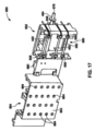
別の実施形態において、バイオプロセッシングのための装置は、ハウジングとハウジング内に収容可能であるドロワーとを備える。ドロワーは、処理チャンバー(processing chamber)を画成する複数の側壁および底部と、一般的に開いている頂部とを備える。ドロワーは、ドロワーがハウジング内に受け入れられる閉鎖位置と、ドロワーがハウジングから伸長し開いている頂部を通る処理チャンバーへのアクセスを可能にする開放位置との間で移動可能である。装置は、また、処理チャンバー内に位置決めされ、バイオリアクター容器(bioreactor vessel)を受け入れるように構成されている少なくとも1つのベッドプレート(bed plate)も備える。 In another embodiment, an apparatus for bioprocessing includes a housing and a drawer receivable within the housing. The drawer includes a plurality of sidewalls and a bottom that define a processing chamber and a generally open top. The drawer is movable between a closed position in which the drawer is received within the housing and an open position in which the drawer extends from the housing and allows access to the processing chamber through an open top. The apparatus also includes at least one bed plate positioned within the processing chamber and configured to receive a bioreactor vessel.
別の実施形態において、バイオプロセッシングの方法は、複数の側壁、底部、および一般的に開いている頂部を有するドロワーをハウジング内の閉鎖位置から開放位置へ摺動させてドロワーをハウジングから伸長させて一般的に開いている頂部に通すステップと、バイオリアクター容器を、一般的に開いている頂部を通して、ドロワー内に位置決めされている静止しているベッドプレート上に位置決めするステップと、ドロワーを摺動して閉鎖位置にするステップと、複数の流体流路を少なくとも1つのポンプおよび複数のピンチ弁線形アクチュエータと係合させるようにドロワー係合アクチュエータを制御するステップとを含む。 In another embodiment, a method of bioprocessing includes sliding a drawer having a plurality of sidewalls, a bottom, and a generally open top from a closed position within a housing to an open position to extend the drawer from the housing. passing the bioreactor vessel through the generally open top and positioning the bioreactor vessel onto a stationary bed plate positioned within the drawer; and sliding the drawer. and controlling the drawer engagement actuator to engage the plurality of fluid flow paths with the at least one pump and the plurality of pinch valve linear actuators.
別の実施形態において、バイオプロセッシングのためのシステムは、ハウジングと、ハウジング内に受け入れ可能である第1のドロワーであって、第1の処理チャンバーを画成する複数の側壁および底部と、一般的に開いている頂部とを備える、第1のドロワーと、第1のドロワーの処理チャンバー内に位置決めされ、その上に第1のバイオリアクター容器を受け入れるか、または他の何らかの形で係合するように構成されている少なくとも1つの第1のベッドプレートと、第1のドロワーと積み重ね関係にあるハウジング内に受け入れ可能である第2のドロワーであって、第2の処理チャンバーを画成する複数の側壁および底部と、一般的に開いている頂部とを備える、第2のドロワーと、第2のドロワーの処理チャンバー内に位置決めされ、その上に第2のバイオリアクター容器を受け入れるか、または他の何らかの形で係合するように構成されている少なくとも1つの第2のベッドプレートとを備える。第1のドロワーおよび第2のドロワーは、各々、第1のドロワーおよび/または第2のドロワーがハウジング内に受け入れられる閉鎖位置と、第1のドロワーおよび/または第2のドロワーがハウジングから伸長してそれぞれ開いている頂部を通る処理チャンバーへのアクセスを可能にする開放位置との間で移動可能である。 In another embodiment, a system for bioprocessing includes a housing, a first drawer receivable within the housing, the plurality of sidewalls and a bottom defining a first processing chamber; a first drawer positioned within the processing chamber of the first drawer to receive or otherwise engage a first bioreactor vessel thereon; and a second drawer receivable within the housing in stacked relationship with the first drawer, the plurality of drawers defining a second processing chamber. a second drawer having a sidewall and a bottom and a generally open top; a second drawer positioned within the processing chamber of the second drawer to receive a second bioreactor vessel thereon; at least one second bed plate configured to engage in some manner. The first drawer and the second drawer each have a closed position in which the first drawer and/or the second drawer are received within the housing and a closed position in which the first drawer and/or the second drawer extend from the housing. and an open position allowing access to the processing chamber through the respective open tops.
さらに別の実施形態において、バイオプロセッシングのための装置は、ハウジングと、ハウジング内に受け入れ可能であるドロワーであって、ドロワーは処理チャンバーを画成する複数の側壁および底面と、一般的に開いている頂部とを備え、ドロワーはドロワーがハウジング内に受け入れられる閉鎖位置と、ドロワーがハウジングから伸長し開いている頂部を通る処理チャンバーへのアクセスを可能にする開放位置との間で移動可能である、ドロワーと、底面に隣接する処理チャンバー内に位置決めされた少なくとも1つのベッドプレートと、処理チャンバー内に受け入れ可能であるキットとを具備する。キットは、内部コンパートメントを画成する複数の側壁および底面と、一般的に開いている頂部と、キットの底面内に形成され、周を有する開口部と、バイオリアクター容器であって、内部コンパートメント内の少なくとも1つの開口部の上に位置決めされ、バイオリアクター容器の一部が底面内の開口部を通してアクセス可能であるように底面によって支持されている、バイオリアクター容器とを備える。キットは、ベッドプレートがトレイの底面内の開口部を貫通しキットの底面の上にバイオリアクター容器を支持するように処理チャンバー内に受け入れ可能である。 In yet another embodiment, an apparatus for bioprocessing includes a housing and a drawer receivable within the housing, the drawer having a plurality of sidewalls and a bottom surface defining a processing chamber and a generally open the drawer is movable between a closed position in which the drawer is received within the housing and an open position in which the drawer extends from the housing to provide access to the processing chamber through the open top. , a drawer, at least one bed plate positioned within the processing chamber adjacent the bottom, and a kit receivable within the processing chamber. The kit includes a bioreactor vessel having a plurality of sidewalls and a bottom surface defining an internal compartment, a generally open top, and an opening formed in the bottom surface of the kit and having a periphery. a bioreactor vessel positioned over at least one opening of the bioreactor vessel and supported by the bottom such that a portion of the bioreactor vessel is accessible through the opening in the bottom. The kit is receivable within the processing chamber such that the bed plate passes through an opening in the bottom of the tray and supports the bioreactor vessel over the bottom of the kit.
さらに別の実施形態において、バイオプロセッシングのためのシステムは、内部コンパートメントを画成する複数の側壁および底面と、一般的に開いている頂部とを有するトレイと、底面内に形成され、周を有する、少なくとも1つの開口部と、トレイと一体化され、少なくとも1つのポンプチューブを受け入れ、ポンプとの選択的係合のために少なくとも1つのポンプチューブを適所に保持するように構成されている第1のチュービングホルダーブロックと、トレイと一体化され、複数のピンチ弁チューブを受け入れ、ピンチ弁アレイのそれぞれのアクチュエータとの選択的係合のために複数のピンチ弁チューブのうちの各ピンチ弁チューブを適所に保持するように構成されている第2のチュービングホルダーブロックと、バイオリアクター容器であって、内部コンパートメント内の少なくとも1つの開口部の上に位置決めされ、バイオリアクター容器の一部が底面内の開口部を通してアクセス可能であるように底面によって支持されている、バイオリアクター容器とを備える。 In yet another embodiment, a system for bioprocessing includes a tray having a plurality of sidewalls and a bottom surface defining an internal compartment and a generally open top surface formed within the bottom surface and having a perimeter. , a first integral with the tray and configured to receive the at least one pump tube and hold the at least one pump tube in place for selective engagement with the pump; a tubing holder block integrated with the tray for receiving a plurality of pinch valve tubes and positioning each pinch valve tube of the plurality of pinch valve tubes for selective engagement with a respective actuator of the pinch valve array; a second tubing holder block configured to retain the bioreactor vessel, the bioreactor vessel being positioned over the at least one opening in the internal compartment, and a portion of the bioreactor vessel being positioned over the opening in the bottom surface; a bioreactor vessel supported by a bottom surface such that it is accessible through the bioreactor vessel.
さらに別の実施形態において、バイオプロセッシングのためのシステムは、複数の側壁と、底面と、一般的に開いている頂部とを有する処理チャンバーと、底面に隣接する処理チャンバー内に位置決めされたベッドプレートと、トレイとを備える。トレイは、内部コンパートメントを画成する複数の側壁および底面と、一般的に開いている頂部とを有するトレイと、トレイの底面内にあり、周を有する開口部とを備える。開口部の周は、バイオリアクター容器が開口部の上に位置決めされ、バイオリアクター容器の一部が底面内の開口部を通してアクセス可能である間にトレイの底面によって支持され得るような形状および/または寸法を有する。トレイは、ベッドプレートがトレイの底面内の開口部を貫通しバイオリアクター容器を支持するように処理チャンバー内に受け入れ可能である。 In yet another embodiment, a system for bioprocessing includes a processing chamber having a plurality of sidewalls, a bottom surface, and a generally open top, and a bed plate positioned within the processing chamber adjacent the bottom surface. and a tray. The tray includes a tray having a plurality of sidewalls and a bottom surface defining an interior compartment, a generally open top, and an opening in the bottom surface of the tray having a periphery. The perimeter of the opening is shaped and/or such that the bioreactor vessel can be positioned over the opening and supported by the bottom of the tray while a portion of the bioreactor vessel is accessible through the opening in the bottom. It has dimensions. The tray is receivable within the processing chamber such that the bed plate passes through an opening in the bottom of the tray and supports the bioreactor vessel.
さらに別の実施形態において、バイオプロセッシングのためのシステムは、内部コンパートメントを画成する複数の側壁および底面と、一般的に開いている頂部とを有するトレイと、周縁を境界とする、底面内の少なくとも1つの開口部であって、開口部は、バイオリアクター容器が開口部の上に位置決めされ、内部コンパートメント内でトレイの底面によって支持され得るような形状および/または寸法を有する、開口部とを備える。 In yet another embodiment, a system for bioprocessing includes a tray having a plurality of sidewalls and a bottom surface defining an internal compartment and a generally open top, a tray in the bottom surface bounded by a periphery. at least one opening, the opening having a shape and/or dimensions such that a bioreactor container can be positioned over the opening and supported by the bottom of the tray within the internal compartment. Be prepared.
さらに別の実施形態において、バイオプロセッシングの方法は、バイオリアクター容器を使い捨てトレイ内に置くステップであって、使い捨てトレイは内部コンパートメントを画成する複数の側壁および底面と、一般的に開いている頂部と、底面内に形成された開口部と、底面から開口部内に貫入する複数のツメまたは突出部とを有する、ステップと、バイオリアクター容器をトレイ内に、バイオリアクター容器が開口部の上の複数のツメによって支持されるように配置構成するステップと、トレイをベッドプレートを有する処理チャンバー内に、ベッドプレートがトレイ内の開口部を通して受け入れられ、バイオリアクター容器を支持するように置くステップとを含む。 In yet another embodiment, a method of bioprocessing includes placing a bioreactor container within a disposable tray, the disposable tray having a plurality of sidewalls and a bottom surface defining an internal compartment and a generally open top surface. a step having an opening formed in the bottom surface and a plurality of tabs or protrusions extending from the bottom surface into the opening; and placing the tray within a processing chamber having a bedplate such that the bedplate is received through an opening in the tray and supports the bioreactor vessel. .
さらに別の実施形態において、バイオプロセッシングシステムのためのチュービングモジュールは、少なくとも1つのポンプチューブを受け入れ、蠕動ポンプとの選択的係合のために少なくとも1つのポンプチューブを適所に保持するように構成されている第1のチュービングホルダーブロックと、複数のピンチ弁チューブを受け入れ、ピンチ弁アレイのそれぞれのアクチュエータとの選択的係合のために複数のピンチ弁チューブのうちの各ピンチ弁チューブを適所に保持するように構成されている第2のチュービングホルダーブロックとを備える。第1のチュービングホルダーブロックおよび第2のチュービングホルダーブロックは相互接続される。 In yet another embodiment, a tubing module for a bioprocessing system is configured to receive at least one pump tube and hold the at least one pump tube in place for selective engagement with a peristaltic pump. a first tubing holder block that receives a plurality of pinch valve tubes and holds each pinch valve tube of the plurality of pinch valve tubes in place for selective engagement with a respective actuator of the pinch valve array; and a second tubing holder block configured to. The first tubing holder block and the second tubing holder block are interconnected.
さらに別の実施形態において、バイオプロセッシングのためのシステムは、内部コンパートメントを画成する複数の側壁および底面と、一般的に開いている頂部とを有し、トレイはバイオリアクター容器を受け入れるか、支持するか、またはその上に他の何らかの形で係合するように構成されているトレイと、トレイの後側壁に隣接して位置決めされているポンプアセンブリと、トレイの後側壁に隣接して位置決めされているピンチ弁アレイと、トレイの後部に位置決めされたチュービングモジュールとを備える。チュービングモジュールは、少なくとも1つのポンプチューブを受け入れ、ポンプアセンブリとの選択的係合のために少なくとも1つのポンプチューブを適所に保持するように構成されている第1のチュービングホルダーブロックと、複数のピンチ弁チューブを受け入れ、ピンチ弁アレイのそれぞれのアクチュエータとの選択的係合のために複数のピンチ弁チューブのうちの各ピンチ弁チューブを適所に保持するように構成されている第2のチュービングホルダーブロックとを備える。 In yet another embodiment, a system for bioprocessing has a plurality of sidewalls and a bottom surface defining an interior compartment and a generally open top, wherein the tray receives or supports a bioreactor vessel. a pump assembly positioned adjacent to the rear wall of the tray; a pump assembly positioned adjacent to the rear wall of the tray; and a tubing module positioned at the rear of the tray. The tubing module includes a first tubing holder block configured to receive at least one pump tube and hold the at least one pump tube in place for selective engagement with the pump assembly, and a plurality of pinch pins. a second tubing holder block configured to receive the valve tubes and hold each pinch valve tube of the plurality of pinch valve tubes in place for selective engagement with a respective actuator of the pinch valve array; Equipped with.
さらに別の実施形態において、バイオリアクター容器は、底プレートと、底プレートに結合された容器本体部であって、容器本体部および底プレートはそれらの間に内部コンパートメントを画成する、容器本体部と、底プレート内に形成された複数の陥凹部であって、複数の陥凹部のうちの各陥凹部はベッドプレート上でバイオリアクター容器を位置合わせするためにベッドプレート上の対応する位置合わせピンを受け入れるように構成されている、複数の陥凹部とを備える。 In yet another embodiment, the bioreactor vessel includes a bottom plate and a vessel body coupled to the bottom plate, the vessel body and the bottom plate defining an interior compartment therebetween. and a plurality of recesses formed in the bottom plate, each recess of the plurality of recesses having a corresponding alignment pin on the bedplate for aligning the bioreactor vessel on the bedplate. a plurality of recesses configured to receive the recesses.
さらに別の実施形態において、バイオプロセッシングのための方法は、底プレートを容器本体部に、それらの間に内部コンパートメントを画成するように動作可能に接続することであって、底プレートおよび容器本体部はバイオリアクター容器を形成する、接続することと、底プレート内の陥凹部をバイオプロセッシングシステムの位置合わせピンと位置合わせすることと、バイオリアクター容器をバイオプロセッシングシステムのベッドプレート上に据え付けることとを含む。 In yet another embodiment, a method for bioprocessing includes operably connecting a bottom plate to a container body to define an internal compartment therebetween, the bottom plate and the container body comprising: The parts include forming and connecting a bioreactor vessel, aligning recesses in the bottom plate with alignment pins of the bioprocessing system, and mounting the bioreactor vessel on the bed plate of the bioprocessing system. include.
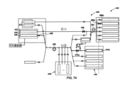
さらに別の実施形態において、バイオプロセッシングシステムは、第1のバイオリアクター容器の第1のバイオリアクター管路を通して第1のバイオリアクター容器の第1のポートに接続されている第1の流体アセンブリ管路を有する第1の流体アセンブリであって、第1のバイオリアクター容器の第1のバイオリアクター管路は第1の流体アセンブリと第1のバイオリアクター容器の第1のポートとの間の選択的な流体連通をもたらすための第1のバイオリアクター管路弁を備える、第1の流体アセンブリと、第1のバイオリアクター容器の第2のバイオリアクター管路を通して第1のバイオリアクター容器の第2のポートに接続されている第2の流体アセンブリ管路を有する第2の流体アセンブリであって、第1のバイオリアクター容器の第2のバイオリアクター管路は第2の流体アセンブリと第1のバイオリアクター容器の第2のポートとの間の選択的な流体連通をもたらすための第2のバイオリアクター管路弁を備える、第2の流体アセンブリと、第1の流体アセンブリと第2の流体アセンブリとの間の流体連通、および第1のバイオリアクター容器の第2のバイオリアクター管路と第1のバイオリアクター容器の第1のバイオリアクター管路との間の流体連通をもたらす相互接続管路とを備える。 In yet another embodiment, the bioprocessing system includes a first fluid assembly line connected to a first port of the first bioreactor vessel through a first bioreactor line of the first bioreactor vessel. a first fluid assembly having: a first bioreactor conduit of the first bioreactor vessel having a selective connection between the first fluid assembly and a first port of the first bioreactor vessel; a first fluid assembly comprising a first bioreactor line valve for providing fluid communication through a second bioreactor line of the first bioreactor vessel to a second port of the first bioreactor vessel; a second fluid assembly having a second fluid assembly line connected to the first bioreactor vessel, wherein the second bioreactor line of the first bioreactor vessel is connected to the second fluid assembly and the first bioreactor vessel; a second fluid assembly comprising a second bioreactor line valve for providing selective fluid communication between the second port of the bioreactor and the first fluid assembly and the second fluid assembly; and an interconnecting line providing fluid communication between the second bioreactor line of the first bioreactor vessel and the first bioreactor line of the first bioreactor vessel.
さらに別の実施形態において、バイオプロセッシングの方法は、第1のバイオリアクター容器の第1のバイオリアクター管路を通して第1のバイオリアクター容器の第1のポートに接続されている第1の流体アセンブリ管路を有する第1の流体アセンブリを提供することと、第1のバイオリアクター容器の第2のバイオリアクター管路を通して第1のバイオリアクター容器の第2のポートに接続されている第2の流体アセンブリ管路を有する第2の流体アセンブリを提供することと、第1のバイオリアクター容器の第2のバイオリアクター管路と第1のバイオリアクター容器の第1のバイオリアクター管路との間の相互接続管路を提供することであって、相互接続管路は第1の流体アセンブリと第2の流体アセンブリとの間の流体連通、および第1のバイオリアクター容器の第2のバイオリアクター管路と第1のバイオリアクター容器の第1のバイオリアクター管路との間の流体連通を可能にする、相互接続管路を提供することとを含む。 In yet another embodiment, the method of bioprocessing includes a first fluid assembly tube connected to a first port of the first bioreactor vessel through a first bioreactor conduit of the first bioreactor vessel. and a second fluid assembly connected to a second port of the first bioreactor vessel through a second bioreactor conduit of the first bioreactor vessel. providing a second fluid assembly having a conduit and an interconnection between a second bioreactor conduit of the first bioreactor vessel and a first bioreactor conduit of the first bioreactor vessel; providing a conduit, the interconnecting conduit providing fluid communication between the first fluid assembly and the second fluid assembly and the second bioreactor conduit and the second bioreactor vessel of the first bioreactor vessel; and providing an interconnecting line that allows fluid communication between one bioreactor vessel and a first bioreactor line.
さらに別の実施形態において、細胞療法のためのバイオプロセッシング方法は、遺伝子改変細胞の集団を産生するためにバイオリアクター容器内で細胞の集団を遺伝子改変することと、バイオリアクター容器から遺伝子改変細胞の集団を取り出すことなく細胞療法治療において使用する1つまたは複数の用量に対して十分な数の遺伝子改変細胞を生成するためにバイオリアクター容器内で遺伝子改変細胞の集団を増幅することとを含む。 In yet another embodiment, a bioprocessing method for cell therapy comprises genetically modifying a population of cells in a bioreactor vessel to produce a population of genetically modified cells; amplifying a population of genetically modified cells in a bioreactor vessel to generate a sufficient number of genetically modified cells for one or more doses for use in a cell therapy treatment without removing the population.
さらに別の実施形態において、バイオプロセッシング方法は、細胞の集団の遺伝子改変の効率を高めるために試薬でバイオリアクター容器をコーティングすることと、遺伝子改変細胞の集団を産生するために細胞の集団の細胞を遺伝子改変することと、バイオリアクター容器から遺伝子改変細胞を取り出すことなくバイオリアクター容器内で遺伝子改変細胞の集団を増幅することとを含む。 In yet another embodiment, a bioprocessing method comprises coating a bioreactor vessel with a reagent to increase the efficiency of genetic modification of a population of cells; and amplifying the population of genetically modified cells within the bioreactor vessel without removing the genetically modified cells from the bioreactor vessel.
さらに別の実施形態において、バイオプロセッシング方法は、活性化された細胞の集団を産生するために磁気または非磁気ビーズを使用してバイオリアクター容器内で細胞の集団の細胞を活性化することと、遺伝子改変細胞の集団を産生するためにバイオリアクター容器内で活性化された細胞を遺伝子改変することと、望ましくない物質を取り除くためにバイオリアクター容器内で遺伝子改変細胞を洗浄することと、形質導入された細胞の増幅された集団を産生するためにバイオリアクター容器内で遺伝子改変細胞の集団を増幅することとを含む。活性化、遺伝子改変、洗浄、および増幅は、バイオリアクター容器から細胞を取り出すことなくバイオリアクター容器内で実行される。 In yet another embodiment, a bioprocessing method comprises activating cells of a population of cells in a bioreactor vessel using magnetic or non-magnetic beads to produce a population of activated cells; Genetically modifying the activated cells in a bioreactor vessel to produce a population of genetically modified cells, washing the genetically modified cells within the bioreactor vessel to remove undesirable substances, and transduction. and amplifying the population of genetically modified cells in a bioreactor vessel to produce an expanded population of cells that have undergone genetic modification. Activation, genetic modification, washing, and amplification are performed within the bioreactor vessel without removing the cells from the bioreactor vessel.
さらに別の実施形態において、バイオプロセッシングシステムにおいて使用するキットは、プロセスバッグと、ソースバッグと、ビーズ追加容器と、プロセスバッグ、ソースバッグ、およびビーズ追加容器と流体連通しているように構成されているプロセスループとを備える。プロセスループは、それに加えて、ポンプと流体連通しているように構成されているポンプチュービングを備える。 In yet another embodiment, a kit for use in a bioprocessing system is configured to have a process bag, a source bag, a bead addition container, and in fluid communication with the process bag, the source bag, and the bead addition container. A process loop is provided. The process loop additionally includes pump tubing configured to be in fluid communication with the pump.
さらに別の実施形態において、バイオプロセッシングのための装置は、プロセスバッグと、ソースバッグと、プロセスループと流体連通しているように構成されているビーズ追加容器とを備えるキットであって、プロセスループは、それに加えて、ポンプと流体連通しているように構成されているポンプチュービングを備える、キットと、磁場を発生させるように構成されている磁場発生器と、ソースバッグ、プロセスバッグ、およびビーズ追加容器を吊り下げるための複数のフックであって、複数のフックの各フックは、ロードセルに動作可能に接続され、ロードセルはそれに接続されているバッグの重量を感知するように構成されている、フックと、少なくとも1つの気泡センサと、プロセスループと流体連通しているように構成されているポンプとを備える。 In yet another embodiment, an apparatus for bioprocessing is a kit comprising a process bag, a source bag, and a bead addition container configured to be in fluid communication with a process loop, the kit comprising: further includes a kit comprising pump tubing configured to be in fluid communication with the pump, a magnetic field generator configured to generate a magnetic field, a source bag, a process bag, and beads. a plurality of hooks for suspending additional containers, each hook of the plurality of hooks being operably connected to a load cell, the load cell being configured to sense the weight of a bag connected thereto; A hook, at least one air bubble sensor, and a pump configured to be in fluid communication with the process loop.
一実施形態において、バイオプロセッシングの方法は、懸濁液中にビーズ結合細胞(bead-bound cell)の集団を形成するために細胞の集団を含む懸濁液を磁気ビーズと組み合わせることと、磁気単離カラム上でビーズ結合細胞の集団を単離することと、細胞の集団から標的細胞を捕集することとを含む。 In one embodiment, a method of bioprocessing includes combining a suspension containing a population of cells with magnetic beads to form a population of bead-bound cells in suspension; The method includes isolating a population of bead-bound cells on a separate column and collecting target cells from the population of cells.
一実施形態において、システムは、磁場パラメータの下で磁場を発生させるように構成されている磁場発生器と、磁場発生器に取り外し可能に結合されるように構成されている第1のホルダーと、磁場発生器に取り外し可能に結合されるように構成されている第2のホルダーとを備える。第1のホルダーは、第1のホルダーが磁場発生器に結合されたときに第1の配置で磁場内に位置決めされるように構成されている通路を有する。第2のホルダーは、第2のホルダーが磁場発生器に結合されたときに第2の配置で磁場内に位置決めされるように構成されている通路を有する。第1のホルダーの通路は第1の配置における磁場パラメータの下で発生される磁場内で第1の磁場強度と第1の磁場勾配の作用を受ける。第2のホルダーの通路は第2の配置における磁場パラメータの下で磁場内で第2の磁場強度と第2の磁場勾配の作用を受け、第2の磁場強度は第1の磁場強度と異なり、第2の磁場勾配は第1の磁場勾配と異なるか、またはこれらの組合せである。 In one embodiment, the system includes: a magnetic field generator configured to generate a magnetic field under magnetic field parameters; a first holder configured to be removably coupled to the magnetic field generator; a second holder configured to be removably coupled to the magnetic field generator. The first holder has a passage configured to be positioned within the magnetic field in a first configuration when the first holder is coupled to the magnetic field generator. The second holder has a passage configured to be positioned within the magnetic field in a second configuration when the second holder is coupled to the magnetic field generator. The passageway of the first holder is subjected to a first magnetic field strength and a first magnetic field gradient within a magnetic field generated under magnetic field parameters in the first configuration. The passageway of the second holder is subjected to a second magnetic field strength and a second magnetic field gradient within the magnetic field under magnetic field parameters in a second configuration, the second magnetic field strength being different from the first magnetic field strength; The second magnetic field gradient is different from the first magnetic field gradient or a combination thereof.
別の実施形態において、磁気細胞単離ホルダーは、磁場発生器に取り外し可能に結合されるように構成されている本体部を備える。本体部は、ホルダーが磁場発生器に結合されたときに第1の配置で磁場発生器の磁場内に位置決めされるように構成されている第1の通路と、ホルダーが磁場発生器に結合されたときに第2の配置で磁場内に位置決めされるように構成されている第2の通路とを有する。第1の通路は第1の配置における磁場パラメータの下で発生される磁場内で第1の磁場強度と第1の磁場勾配の作用を受け、第2の通路は第2の配置における磁場パラメータの下で磁場内で第2の磁場強度と第2の磁場勾配の作用を受ける。第2の磁場強度は第1の磁場強度と異なり、第2の磁場勾配は第1の磁場勾配と異なるか、またはこれらの組合せである。 In another embodiment, the magnetic cell isolation holder comprises a body configured to be removably coupled to a magnetic field generator. The body portion has a first passage configured to be positioned within the magnetic field of the magnetic field generator in a first configuration when the holder is coupled to the magnetic field generator; a second passageway configured to be positioned within the magnetic field in a second configuration when The first passage is subjected to a first magnetic field strength and a first magnetic field gradient in a magnetic field generated under magnetic field parameters in a first configuration, and the second passage is subjected to a first magnetic field gradient in a magnetic field generated under magnetic field parameters in a first configuration. under the influence of a second magnetic field strength and a second magnetic field gradient within the magnetic field. The second magnetic field strength is different from the first magnetic field strength, and the second magnetic field gradient is different from the first magnetic field gradient, or a combination thereof.
別の実施形態において、システムは、複数の第1のサイズのビーズと複数の第1のサイズのビーズを受け入れるように構成されている通路を有する第1のホルダーとを有する第1のキットと、複数の第2のサイズのビーズと複数の第2のサイズのビーズを受け入れるように構成されている通路を有する2のホルダーとを有する第2のキットとを備える。第1のホルダーの通路は、第1のホルダーが磁場発生器に取り外し可能に結合されたときに、第1のホルダーが第1の配置で磁場発生器によって発生される磁場内に位置決めされるようにホルダー内に位置決めされる。第2のホルダーの通路は、第2のホルダーが磁場発生器に取り外し可能に結合されたときに、第2のホルダーが第1の配置と異なる第2の配置で磁場発生器によって発生される磁場内に位置決めされるように第2のホルダー内に位置決めされる。第1のホルダーの通路は第1の配置において磁場内で第1の磁場強度と第1の磁場勾配の作用を受け、第2のホルダーの通路は第2の配置において磁場内で第2の磁場強度と第2の磁場勾配の作用を受ける。第2の磁場強度は第1の磁場強度と異なり、第2の磁場勾配は第1の磁場勾配と異なるか、またはこれらの組合せである。 In another embodiment, the system includes a first kit having a plurality of first size beads and a first holder having a passageway configured to receive the plurality of first size beads; a second kit having a plurality of second size beads and two holders having passageways configured to receive the plurality of second size beads. The passageway in the first holder is configured such that when the first holder is removably coupled to the magnetic field generator, the first holder is positioned within the magnetic field generated by the magnetic field generator in the first configuration. is positioned within the holder. The passageway in the second holder is arranged such that when the second holder is removably coupled to the magnetic field generator, the second holder receives the magnetic field generated by the magnetic field generator in a second configuration that is different from the first configuration. the second holder such that the second holder is positioned within the second holder; The passages of the first holder are subjected to a first magnetic field strength and a first magnetic field gradient in a magnetic field in a first configuration, and the passages of the second holder are subjected to a second magnetic field in a magnetic field in a second configuration. influenced by the intensity and the second magnetic field gradient. The second magnetic field strength is different from the first magnetic field strength, and the second magnetic field gradient is different from the first magnetic field gradient, or a combination thereof.
別の実施形態において、標的細胞を単離するための方法は、磁場発生器に結合されているフレームの受け入れ領域内に通路を有する第1のホルダーを位置決めすることと、第1のホルダーの通路に第1の磁場強度、第1の磁場勾配、またはその両方を作用させるために第1のホルダーが磁場発生器に結合されたときに磁場発生器により受け入れ領域内に第1の磁場を発生させることとを含む。方法は、また、受け入れ領域内に通路を有する第2のホルダーを位置決めすることと、第2のホルダーの通路に第2の磁場強度、第2の磁場勾配、またはその両方を作用させるために第2のホルダーが磁場発生器に結合されたときに磁場発生器により受け入れ領域内に第2の磁場を発生させることとを含む。第1のホルダーの通路および第2のホルダーの通路は、受け入れ領域内の異なる位置に位置決めされる。 In another embodiment, a method for isolating target cells includes positioning a first holder having a passage within a receiving region of a frame coupled to a magnetic field generator; generating a first magnetic field within the receiving region by the magnetic field generator when the first holder is coupled to the magnetic field generator to exert a first magnetic field strength, a first magnetic field gradient, or both; Including things. The method also includes positioning a second holder having a passageway within the receiving region and applying a second magnetic field strength, a second magnetic field gradient, or both to the passageway of the second holder. generating a second magnetic field within the receiving region by the magnetic field generator when the second holder is coupled to the magnetic field generator. The first holder passage and the second holder passage are positioned at different positions within the receiving area.
本発明は、以下に示す、添付図面を参照しつつ、非限定的な実施形態の次の説明を読むことでさらによく理解されるであろう。 The invention will be better understood on reading the following description of non-limiting embodiments, given below and with reference to the accompanying drawings, in which: FIG.
例が添付図面に示されている、本発明の例示的な実施形態が以下で詳細に参照される。可能な限り、図面全体を通して同じまたは類似の部分を指すために同じ参照文字が使用される。 Reference will now be made in detail to exemplary embodiments of the invention, examples of which are illustrated in the accompanying drawings. Wherever possible, the same reference characters are used throughout the drawings to refer to the same or like parts.
本明細書で使用されているように、「柔軟性がある」または「折り畳み可能である」という語は、曲げやすいか、または破壊することなく曲げることができる構造または材料を指し、圧縮可能または膨張可能である材料も指し得る。柔軟性のある構造の一例は、ポリエチレンフィルムから形成されたバッグである。「剛体の」および「半剛体の」という語は、本明細書では、「非折り畳み可能」である構造、すなわち、通常の力が加わって折り畳まれる、つぶれる、または他の何らかの形で変形してその細長寸法を著しく縮小することのない構造を記述するために交換可能に使用される。文脈に応じて、「半剛体の」は、「剛体」要素より柔軟である構造、たとえば、曲げられるチューブまたは導管を表すこともできるが、それでも、通常の条件および力の下で縦方向につぶれない構造を表すことができる。 As used herein, the terms "flexible" or "foldable" refer to a structure or material that is flexible or capable of being bent without breaking, compressible or It can also refer to materials that are expandable. An example of a flexible structure is a bag formed from polyethylene film. The terms "rigid" and "semi-rigid" are used herein to refer to structures that are "non-foldable," i.e., capable of folding, collapsing, or otherwise deforming under the application of normal forces. Used interchangeably to describe a structure without significantly reducing its elongated dimensions. Depending on the context, "semi-rigid" can also describe a structure that is more flexible than a "rigid" element, such as a tube or conduit that can be bent, but still collapses longitudinally under normal conditions and forces. can represent a structure that does not exist.
本明細書で使用されているような、「容器」は、場合に応じて、柔軟なバッグ、柔軟な入れ物、半剛体の入れ物、剛体の入れ物、または柔軟なもしくは半剛体のチュービングを意味する。本明細書で使用されているような「容器」という語は、半剛体または剛体である壁または壁の一部を有するバイオリアクター容器、さらにはたとえば、細胞培養/精製システム、混合システム、培地/バッファ調製システム、および濾過/精製システム、たとえば、クロマトグラフィおよび接線流濾過システム、ならびにその関連する流路を含む、生物学的または生化学的処理で普通に使用される他の入れ物もしくは導管を包含することを意図されている。本明細書で使用されているように、「バッグ」という語は、たとえば、様々な流体および/または培地のための封じ込めデバイスとして使用される柔軟なもしくは半剛体の入れ物または容器を意味する。 As used herein, "container" means a flexible bag, flexible container, semi-rigid container, rigid container, or flexible or semi-rigid tubing, as the case may be. The term "vessel" as used herein refers to bioreactor vessels having walls or portions of walls that are semi-rigid or rigid, as well as, for example, cell culture/purification systems, mixing systems, media/ Buffer preparation systems, and filtration/purification systems, including other vessels or conduits commonly used in biological or biochemical processing, including chromatography and tangential flow filtration systems and their associated flow paths. is intended. As used herein, the term "bag" refers to a flexible or semi-rigid container or container used, for example, as a containment device for various fluids and/or media.
本明細書で使用されているように、「流体結合される」または「流体連通」は、システムのコンポーネントがコンポーネント間で流体を受け入れるか、または移送することができることを意味する。流体という語は、気体、液体、またはこれらの組合せを含む。本明細書で使用されているように、「電気通信」または「電気的に結合される」は、いくつかのコンポーネントは、直接的または間接的電気的接続を用いて直接的または間接的シグナリングを通じて互いに通信するように構成されることを意味する。本明細書で使用されているように、「動作可能に結合される」は、直接的または間接的であり得る、接続を指す。接続は、必ずしも機械的連結ではない。 As used herein, "fluidically coupled" or "fluidic communication" means that components of a system are capable of receiving or transferring fluids between the components. The term fluid includes gases, liquids, or combinations thereof. As used herein, "telecommunications" or "electrically coupled" means that the components of the means configured to communicate with each other. As used herein, "operably coupled" refers to a connection, which may be direct or indirect. A connection is not necessarily a mechanical connection.
本明細書で使用されているように、「トレイ」という語は、複数のコンポーネントを少なくとも一時的に支持することができる、任意の物体を指す。トレイは、様々な好適な材料から作られるものとしてよい。たとえば、トレイは、滅菌および一度きりの使い捨て製品に適した費用効果の高い材料から作られるものとしてよい。 As used herein, the term "tray" refers to any object that can at least temporarily support multiple components. The tray may be made from a variety of suitable materials. For example, the tray may be made from cost-effective materials suitable for sterilization and single-use disposable products.
本明細書で使用されているように、「機能的閉鎖システム」という語は、閉じた流体経路の完全性を損なうことなく(たとえば、内部無菌生物医学流体経路を維持するために)、システムに流体もしくは空気を加えるか、またはシステムから流体もしくは空気を取り除くための、入口ポートおよび出口ポートを有し得る閉じた流体経路を構成する複数のコンポーネントを指し、それによってそれらのポートは、システムに流体もしくは空気が加えられるか、またはシステムから流体もしくは空気が取り除かれたときに、無菌完全性を維持するためにたとえば、フィルターまたは膜を各ポートに含み得る。これらのコンポーネントは、所与の実施形態に応じて、これらに限らないが、1または複数の導管、弁(たとえば、マルチポイントダイバータ)、容器、レセプタクル、およびポートを含み得る。 As used herein, the term "functionally closed system" refers to a system that does not compromise the integrity of the closed fluid pathway (e.g., to maintain an internal sterile biomedical fluid pathway). Refers to a plurality of components that constitute a closed fluid pathway that may have inlet and outlet ports for adding fluid or air to or removing fluid or air from the system, such that the ports Alternatively, each port may include, for example, a filter or membrane to maintain sterile integrity when air is added or fluid or air is removed from the system. These components may include, but are not limited to, one or more conduits, valves (eg, multipoint diverters), containers, receptacles, and ports, depending on the given embodiment.
本発明の実施形態は、生体試料(たとえば、血液、組織、など)から細胞免疫療法薬を製造するためのシステムおよび方法を提供する。一実施形態において、バイオプロセッシングの方法は、細胞の集団を含む懸濁液を磁気ビーズと組み合わせて懸濁液中にビーズ結合細胞の集団を形成することと、磁気分離カラム上のビーズ結合細胞の集団を単離することと、細胞の集団から標的細胞を捕集することとを含む。標的細胞を捕集することは、空気栓を有する単離カラムからビーズ結合細胞を取り除くことを含む。 Embodiments of the invention provide systems and methods for producing cellular immunotherapeutics from biological samples (eg, blood, tissue, etc.). In one embodiment, a method of bioprocessing comprises combining a suspension containing a population of cells with magnetic beads to form a population of bead-bound cells in suspension, and forming a population of bead-bound cells on a magnetic separation column. The method includes isolating the population and collecting target cells from the population of cells. Collecting target cells involves removing bead-bound cells from an isolation column with an air plug.
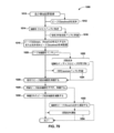
図1を参照すると、本発明の一実施形態によるバイオプロセッシングシステム10の概略図が例示されている。バイオプロセッシングシステム10は、細胞免疫療法薬(たとえば、自己細胞免疫療法薬)の製造において使用するように構成され、たとえば、ヒト血液、流体、組織、または細胞試料が捕集され、捕集された試料から、またはそれに基づき細胞療法薬が生成される。キメラ抗原受容体(CAR)T細胞療法薬はバイオプロセッシングシステム10を使用して製造され得る細胞免疫療法薬の一種であるが、他の細胞療法薬も本発明のより広範な態様から逸脱することなく本発明または本発明の態様のシステムを使用して生産され得る。図1に例示されているように、CAR T細胞療法薬の製造は、一般的に、アフェレーシス療法を通じて患者の血液の捕集およびリンパ球の分離から始まる。捕集/アフェレーシス療法は臨床現場で行われるものとしてよく、次いでアフェレーシス生成物は、CAR T細胞の産生のために研究所または製造施設に送られる。特に、アフェレーシス生成物が処理のために受け取られた後、所望の細胞集団は(たとえば、白血球細胞)、細胞療法薬を製造するために濃縮されるか、または捕集血から分離され、注目する標的細胞は始原細胞混合液から単離される。次いで、注目する標的細胞は活性化され、腫瘍細胞を特定的に標的にし、破壊するように遺伝子改変され、所望の細胞密度を達成するように増幅される。増幅後、細胞は収穫され、用量が配合される。次いで、配合剤は、多くの場合に冷凍保存され、解凍、調製、および最後に、患者体内への輸液注入のために臨床現場に配送される。
Referring to FIG. 1, a schematic diagram of a
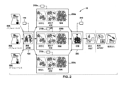
さらに図1を参照すると、本発明のバイオプロセッシングシステム10は、実質的に自動化され、機能的閉鎖されたスケーラブルな方式で製造ステップの特定のサブセットを実行するように各々構成される複数の相異なるモジュールまたはサブシステムを備える。特に、バイオプロセッシングシステム10は、濃縮および単離のステップを実行するように構成されている第1のモジュール100と、活性化、遺伝子改変、および増幅のステップを実行するように構成されている第2のモジュール200と、増幅された細胞集団を収穫するステップを実行するように構成されている第3のモジュール300とを備える。一実施形態において、各モジュール100、200、300は、専用コントローラ(たとえば、第1のコントローラ110、第2のコントローラ210、および第3のコントローラ310、それぞれ)に通信可能に結合され得る。コントローラ110、210、および310は、各モジュール内の製造プロセスに対する実質的に自動化された制御を行うように構成される。第1のモジュール100、第2のモジュール200、および第3のモジュール300は、各モジュールの動作を制御するための専用コントローラを備えるものとして例示されているが、マスター制御ユニットが3つのモジュールに大域的制御を行うために利用されてよいことが企図されている。各モジュール100、200、300は、以下で詳しく説明されているように、単一のコヒーレントバイオプロセッシングシステム10を形成するように他のモジュールと協力して働くように設計されている。
With further reference to FIG. 1, the
各モジュール内のプロセスを自動化することによって、各モジュールからの生成物一貫性が高められ、広範な手動操作に関連するコストが低減され得る。それに加えて、この後で詳しく説明されるように、各モジュール100、200、300は実質的に閉じられ、外部汚染のリスクを下げることによって患者安全性を確実にすることを助け、法規制の順守を確実にし、開放システムにかかわるコストを回避することを助ける。さらに、各モジュール100、200、300はスケーラブルであり、少ない患者数での開発および多い患者数での商業製造の両方を支持する。
By automating the processes within each module, product consistency from each module may be increased and costs associated with extensive manual operations may be reduced. In addition, as detailed below, each
図1をさらに参照すると、プロセスステップが閉鎖および自動化バイオプロセッシングを各々提供する相異なるモジュールに区分される特定の方式は、これ以前にはこの技術分野において見られない程度までの資本設備の効率的利用を可能にする。理解されるように、収穫および配合の前に所望の細胞密度を達成するために細胞集団を増幅するステップは、典型的には、製造プロセスにおいて最も時間のかかるステップであるが、濃縮および単離ステップ、ならびに収穫および配合ステップ、さらには活性化および遺伝子改変ステップはあまり時間がかからない。したがって、細胞療法薬製造プロセス全体を自動化する試みは、ロジスティックに関して困難であることに加えて、ワークフローを妨げ、製造効率を減少させるプロセス内のボトルネックを悪化させ得る。特に、完全自動化プロセスにおいて、細胞の濃縮、単離、活性化、および遺伝子改変のステップは、かなり速く実行することができるが、遺伝子改変された細胞の増幅は、非常にゆっくりと進む。したがって、第1の試料(たとえば、第1の患者の血液)からの細胞療法薬の製造は、増幅ステップまで素早く進行し、これは収穫する所望の細胞密度を達成するために実質的な時間を要する。完全自動化システムを使用した場合、プロセス/システム全体は、第1の試料からの細胞の増幅を実行する増幅機器によって占有され、第2の試料の処理は、システム全体が使用のため解放されるまで開始できない。この点に関して、完全自動化バイオプロセッシングシステムでは、システム全体が本質的にオフラインであり、濃縮から収穫/配合までの細胞療法薬製造プロセス全体が第1の試料において完了するまで第2の試料の処理に利用可能でない。 With further reference to Figure 1, the particular manner in which process steps are partitioned into distinct modules that provide for closed and automated bioprocessing, respectively, increases the efficiency of capital equipment to a degree not previously seen in this art. make available. As will be appreciated, the step of amplifying cell populations to achieve the desired cell density prior to harvest and formulation is typically the most time-consuming step in the manufacturing process, whereas enrichment and isolation The steps, as well as the harvesting and compounding steps, as well as the activation and genetic modification steps, do not take much time. Therefore, attempts to automate the entire cell therapy manufacturing process, in addition to being logistically difficult, can exacerbate bottlenecks within the process that impede workflow and reduce manufacturing efficiency. In particular, in a fully automated process, the cell enrichment, isolation, activation, and genetic modification steps can be performed fairly quickly, whereas the amplification of genetically modified cells proceeds very slowly. Therefore, the production of cell therapy from a first sample (e.g., the blood of a first patient) proceeds quickly up to the amplification step, which takes a substantial amount of time to achieve the desired cell density to harvest. It takes. When using a fully automated system, the entire process/system is occupied by the amplification equipment performing the amplification of cells from the first sample and the processing of the second sample until the entire system is released for use. Unable to start. In this regard, in fully automated bioprocessing systems, the entire system is essentially off-line and the entire cell therapy drug manufacturing process, from concentration to harvest/formulation, is completed in the first sample until the second sample is processed. Not available.
しかしながら、本発明の実施形態は、資本資源のより効率的な利用を進めるために複数の試料(同じまたは異なる患者からの)の並列処理を可能にする。この利点は、上でほのめかしたように、プロセスステップが3つのモジュール100、200、300に分けられる特定の方式の直接的結果である。図2を特に参照すると、一実施形態において、単一の第1のモジュール100および/または単一の第3のモジュール300は、同じまたは異なる患者からの複数の試料の並列および同期処理を行うために、バイオプロセッシングシステム12において、複数の第2のモジュール、たとえば、第2のモジュール200a、200b、200cと連動して利用することができる。たとえば、第1の患者からの第1のアフェレーシス生成物は、第1のモジュール100を使用して濃縮され単離され、それにより、単離された標的細胞の第1の集団を産生するものとしてよく、標的細胞の第1の集団は、次いで、コントローラ210aの制御の下で、活性化、遺伝子改変、および増幅のために第2のモジュールのうちの1つ、たとえば、モジュール200aに移送され得る。標的細胞の第1の集団が、第1のモジュール100から移送されて出された後、第1のモジュールは、ここでもまた、たとえば、第2の患者からの第2のアフェレーシス生成物の処理に使用するために利用可能である。次いで、第2の患者から取り出された試料から第1のモジュール100において産生された標的細胞の第2の集団は、コントローラ201bの制御の下で活性化、遺伝子改変、および増幅のために、別の第2のモジュール、たとえば、第2のモジュール200bに移送され得る。
However, embodiments of the present invention enable parallel processing of multiple samples (from the same or different patients) to promote more efficient utilization of capital resources. This advantage is a direct result of the particular manner in which the process steps are divided into three
同様に、標的細胞の第2の集団が、第1のモジュール100から移送されて出された後、第1のモジュールは、ここでもまた、たとえば、第3の患者からの第3のアフェレーシス生成物の処理に使用するために利用可能である。次いで、第3の患者から取り出された試料から第1のモジュール100において産生された細胞の第3の標的集団は、コントローラ201cの制御の下で活性化、遺伝子改変、および増幅のために、別の第2のモジュール、たとえば、第2のモジュール200cに移送され得る。この点に関して、第1の患者に対する、たとえば、CAR-T細胞の増幅は、第2の患者、第3の患者などに対するCAR-T細胞の増幅と同時に生じ得る。
Similarly, after the second population of target cells has been transferred and exited from the
このアプローチでも、後処理を必要に応じて非同期に実行するようにできる。言い換えると、患者細胞はすべて同時には成長し得ない。培養物は、異なる時刻に最終密度に到達し得るが、複数の第2のモジュール200はリンクされず、第3のモジュール300は、必要に応じて使用することができる。本発明により、試料は並列に処理できるが、これらはバッチ処理で行われなくてもよい。
This approach also allows post-processing to be performed asynchronously if desired. In other words, patient cells cannot all grow at the same time. The cultures may reach final density at different times, but the multiple
第2のモジュール200a、200b、および200cからの細胞の増幅された集団の収穫は、同様に、細胞の各増幅された集団の収穫の準備が整ったときに単一の第3のモジュール300を使用して遂行され得る。
Harvesting the amplified populations of cells from the
したがって、最も時間がかかり、いくつかの運用上の要件を共有し、および/または類似の培養の条件を要求する、活性化、遺伝子改変、および増幅のステップをスタンドアロンの自動化された機能的に閉じられているモジュールに分けることによって、濃縮、単離、収穫、および配合に利用される他のシステム機器は、細胞の1つの集団の増幅が実行されている間、縛り付けられる、またはオフラインである、ということがない。その結果、複数の細胞療法薬の製造は、同時に実行されてよく、機器および使用床面積を最大化し、プロセス全体および設備の効率を高める。追加の第2のモジュールが、望む通りに、任意の数の細胞集団の並列処理を行うためにバイオプロセッシングシステム10に追加されてよい。したがって、本発明のバイオプロセッシングシステムは、プラグ&プレイに似た機能を使用することを可能にし、製造設備の拡大または縮小を容易に行うことができる。
Therefore, the activation, genetic modification, and amplification steps, which are most time-consuming, share some operational requirements, and/or require similar culture conditions, are closed to stand-alone automated functionally. By dividing the system into modules that are used for enrichment, isolation, harvesting, and formulation, other system equipment is tied down or offline while amplification of one population of cells is performed. There is no such thing. As a result, manufacturing of multiple cell therapy drugs may be performed simultaneously, maximizing equipment and floor space usage and increasing overall process and facility efficiency. Additional second modules may be added to
一実施形態において、第1のモジュール100は、患者から取ったアフェレーシス生成物から、免疫療法薬および再生医療薬の製造などの、生物学的プロセスにおいて使用するために濃縮され、単離された細胞の標的集団を産生することができる任意のシステムまたはデバイスであってよい。たとえば、第1のモジュール100は、GE Healthcareから入手可能な、Sefia Cell Processing Systemの修正バージョンであってよい。本発明のいくつかの実施形態による第1のモジュール100の構成は、この後詳しく説明される。
In one embodiment, the
一実施形態において、第3のモジュール300は、同様に、患者体内に注入して、細胞免疫療法または再生医療で使用するために、第2のモジュール200によって産生されるCAR-T細胞または他の改変細胞を収穫し、および/または配合することができる任意のシステムまたはデバイスであってよい。いくつかの実施形態において、第3のモジュール300は、同様に、GE Healthcareから入手可能な、Sefia Cell Processing Systemであってよい。いくつかの実施形態において、第1のモジュール100は、細胞(その後、活性化、形質導入、および増幅(およびいくつかの実施形態において、収穫)のため第2のモジュール200に移送される)の濃縮および単離に最初に利用され、次いで、細胞収穫および/または配合のためにプロセスの終了時にも使用され得る。この点で、いくつかの実施形態において、同じ機器が、フロントエンドの細胞濃縮および単離ステップ、さらにバックエンドの収穫および/または配合ステップに利用され得る。
In one embodiment, the
最初に、第2のモジュール200に注目すると、上で説明されているワークフローの効率をもたらす単一の機能的に閉じられている自動化されたモジュール200における細胞活性化、遺伝子改変、および細胞増幅のプロセスステップを組み合わせるができることは、第2のモジュール200内のコンポーネントの特定の構成、およびそのようなコンポーネントの間の特定の相互接続性をもたらす固有の流動アーキテクチャによって有効化される。以下で説明される、図3~図77は、本発明の様々な実施形態による第2のモジュール200の様々な態様を例示している。最初に図3を参照すると、細胞活性化、遺伝子改変、および増幅(いくつかの場合において、収穫)を行う第2のモジュール200内の流体流動アーキテクチャ400(バイオプロセッシングサブシステム400またはバイオプロセッシングシステム400とも本明細書において広範に称される)を例示する概略図が示されている。システム400は、第1のバイオリアクター容器410と第2のバイオリアクター容器420とを備える。第1のバイオリアクター容器は、少なくとも第1のポート412および第1のポート412と流体連通している第1のバイオリアクター管路414、ならびに第2のポート416および第2のポート416と流体連通している第2のバイオリアクター管路418を備える。同様に、第2のバイオリアクター容器は、少なくとも第1のポート422および第1のポート422と流体連通している第1のバイオリアクター管路424、ならびに第2のポート426および第2のポート426と流体連通している第2のバイオリアクター管路428を備える。一緒に、第1のバイオリアクター容器410および第2のバイオリアクター容器420は、バイオリアクターアレイ430を形成する。システム400は、2つのバイオリアクター容器を有するものとして示されているが、本発明の実施形態は、単一のバイオリアクターまたは3つ以上のバイオリアクター容器を備え得る。
Focusing first on the
第1および第2のバイオリアクター容器410、420の第1および第2のバイオリアクター管路414、418、424、428は、各々、以下で説明されているように、中を通る流体の流れを制御するためのそれぞれの弁を備える。特に、第1のバイオリアクター容器410の第1のバイオリアクター管路414は、第1のバイオリアクター管路弁432を備え、第1のバイオリアクター容器410の第2のバイオリアクター管路418は、第2のバイオリアクター管路弁424を備える。同様に、第2のバイオリアクター容器420の第1のバイオリアクター管路424は、第1のバイオリアクター管路弁436を備え、第2のバイオリアクター容器420の第2のバイオリアクター管路428は、第2のバイオリアクター管路弁438を備える。
The first and
図3をさらに参照すると、システム400は、また、第1の流体アセンブリ管路442を有する第1の流体アセンブリ440と、第2の流体アセンブリ管路446を有する第2の流体アセンブリ444と、サンプリングアセンブリ448とを備える。相互接続管路弁452を有する相互接続管路450は、第1の流体アセンブリ440と第2の流体アセンブリ444との間を流体連通する。図3に示されているように、相互接続管路450は、また、第2のバイオリアクター管路418と第1のバイオリアクター容器410の第1のバイオリアクター管路414との間を流体連通し、第1のバイオリアクター容器の第1の循環ループに沿って流体の循環を行わせることができる。同様に、相互接続管路は、また、第2のバイオリアクター管路428と第2のバイオリアクター容器420の第1のバイオリアクター管路424との間を流体連通し、第2のバイオリアクター容器の第2の循環ループに沿って流体の循環を行わせることができる。さらに、相互接続管路450は、第1のバイオリアクター容器410の第2のポート416および第2のバイオリアクター管路418と第2のバイオリアクター容器420の第1のポート422および第1のバイオリアクター管路424の間をさらに流体連通し、以下で説明されているように、第1のバイオリアクター容器410の内容物を第2のバイオリアクター容器420に移送することを可能にする。図3に例示されているように、相互接続管路450は、一実施形態において、第2のバイオリアクター管路418、428から第1のバイオリアクター容器410の第1のバイオリアクター管路414と第1の流体アセンブリ管路442との交差部まで延在する。
With further reference to FIG. 3, the
図3に例示されているように、第1および第2の流体アセンブリ440、450は、相互接続管路450に沿って配設される。それに加えて、一実施形態において、第1の流体アセンブリは、第1のバイオリアクター容器410の第1のポート412および第2のバイオリアクター容器420の第1のポートと、それぞれ第1のバイオリアクター容器の第1のバイオリアクター管路414および第2のバイオリアクター容器420の第1のバイオリアクター管路424を通して、流体連通する。第2の流体アセンブリ444は、第1のバイオリアクター容器410の第2のポート416および第2のバイオリアクター容器420の第2のポート426と、相互接続管路450を介して流体連通する。
As illustrated in FIG. 3, first and second
流体を双方向に流すことができる第1のポンプまたは相互接続管路ポンプ454は、第1の流体アセンブリ管路442に沿って配設され、流体を双方向に流すことができる第2のポンプまたは循環管路ポンプ456は、相互接続管路450に沿って配設され、その機能および目的は以下で説明される。一実施形態において、ポンプ454、456は、高ダイナミックレンジポンプである。図3にも示されているように、滅菌空気源458は、滅菌空気源管路460を通して相互接続管路450に接続される。滅菌空気源管路460に沿って位置決めされた弁462は、滅菌空気源458と相互接続管路450との間で選択的流体連通を行う。図3は、相互接続管路450に接続されている滅菌空気源458を示しているが、他の実施形態において、滅菌空気源は、本発明のより広範な態様から逸脱することなく、第1のバイオリアクターまたは第2のバイオリアクターのいずれかの第2のバイオリアクター管路弁と第1のバイオリアクター管路弁との中間で第1の流体アセンブリ440、第2の流体アセンブリ444、または流体流路に接続され得る。
A first pump or
次にそれに加えて図4~図6を参照すると、第1の流体アセンブリ440、第2の流体アセンブリ444、およびサンプリングアセンブリ448の詳細図が示されている。図4を特に参照すると、第1の流体アセンブリ440は複数のチュービングテール464a~fを備え、その各々は複数の第1の貯蔵槽466a~fのうちの1つに選択的/取り外し可能に接続するように構成される。第1の流体アセンブリ440の各チュービングテール464a~fは、第1の流体アセンブリ440の複数の第1の貯蔵槽466a~fのうちのそれぞれ1つへの、またはそれぞれ1つからの流体の流れを選択的に制御するためのチュービングテール弁468a~fを備える。図4は、特に、第1の流体アセンブリ440が6個の流体貯蔵槽を備えることを示しているが、望む通りに、様々な処理流体の投入もしくは捕集のためにより多いもしくはより少ない貯蔵槽が利用されてもよい。各チュービングテール464a~fは、以下で説明されているように、それぞれ、流体アセンブリ440の稼動中に必要とされる時間に、貯蔵層466a~fに個別に接続され得ることが企図される。
4-6, detailed views of the first
図5を特に参照すると、第2の流体アセンブリ444は複数のチュービングテール470a~dを備え、その各々は複数の第2の貯蔵槽472a~dのうちの1つに選択的/取り外し可能に接続するように構成される。第2の流体アセンブリ444の各チュービングテール470a~dは、第1の流体アセンブリ444の複数の第2の貯蔵槽472a~dのうちのそれぞれ1つへの、またはそれぞれ1つからの流体の流れを選択的に制御するためのチュービングテール弁474a~dを備える。図5は、特に、第2の流体アセンブリ444が4個の流体貯蔵槽を備えることを示しているが、望む通りに、様々な処理流体の投入もしくは捕集のためにより多いもしくはより少ない貯蔵槽が利用されてもよい。一実施形態において、第2の貯蔵槽のうちの少なくとも1つ、たとえば、第2の貯蔵槽472dは、以下で説明されているように、細胞の増幅された集団を捕集するための収集貯蔵槽である。一実施形態において、第2の貯蔵槽472aは廃液貯蔵槽であり、その目的は以下で説明される。本発明は、1つまたは複数の貯蔵槽472a~dがそのそれぞれのテール470a~dに事前接続されてよく、各追加の貯蔵槽は第2の流体アセンブリ440内でその使用に間に合わせてそれぞれのテールに接続されることを企図している。
With particular reference to FIG. 5, the second
一実施形態において、第1の貯蔵槽466a~fおよび第2の貯蔵槽472a~dは、一度限りの/使い捨て型の柔軟なバッグである。一実施形態において、バッグは、当技術分野で知られているように、対向するパネルが溶接されるか、またはその周のところで一緒に固定され、それぞれのテールに接続するための接続導管を支持する実質的に二次元のバッグである。
In one embodiment,
一実施形態において、貯蔵槽/バッグは、滅菌溶接デバイスを使用して第1および第2のチュービングアセンブリのチュービングテールに接続され得る。一実施形態において、溶接デバイスはモジュール200の隣に位置決めされ、溶接デバイスはバッグ上のチューブのテールに付くように(無菌状態を維持しながら)チュービングテールのうちの1つを突合せ溶接するために利用される。したがって、操作者は、バッグをそれが必要になったときに提供することができる(たとえば、チュービングテールを掴んで、その自由端を溶接デバイス内に挿入し、バッグをチュービングテールの端部に隣接するバッグチューブの自由端を横にし、新品のカミソリの刃でチューブを切断し、一緒に再固化するようにそのまま溶けている間に2つのチューブ端が力ずくで寄せられている間にカミソリが引き離されるときに切断端部を加熱することによって)。逆に、バッグは、バッグは、バッグからの管路を溶接し、溶接部のところで2本の閉じられた管路を切断することによって取り外され得る。したがって、貯蔵槽/バッグは、望ましいときに個別に接続されてよく、本発明では、操作者がその使用に間に合わせて貯蔵槽/バッグを接続するためにプロセス全体にわたって適切なチュービングテールにアクセスできるのですべての貯蔵槽/バッグがプロトコルの開始時に接続されていなければならないことを必要としない。実際、以下で説明されているように、すべての貯蔵槽/バッグは事前接続されているが、本発明では事前接続を必要とせず、第2のモジュール200の1つの利点は、操作者が操作時に流体アセンブリ/管路にアクセスすることを可能にし、それにより使用済みバッグは滅菌して接続され、他のバッグがプロトコルにおいて滅菌状態で接続できるように切り離され得る、という点である。
In one embodiment, the reservoir/bag may be connected to the tubing tails of the first and second tubing assemblies using a sterile welding device. In one embodiment, a welding device is positioned next to the
図6に例示されているように、サンプリングアセンブリ448は、相互接続管路450に流体接続されている1つまたは複数のサンプリング管路、たとえば、サンプリング管路476a~476dを備える。試料管路476a~476dの各々は、試料管路476a~476dを通して相互接続管路450から流体を流せるように選択可能に作動可能である試料管路弁478a~dを備え得る。そこにも示されているように、各サンプリング管路476a~476dの遠位端は、相互接続管路450から流体を捕集するための試料捕集デバイス(たとえば、試料捕集デバイス280aおよび280d)に選択的に接続するように構成される。試料捕集デバイスは、たとえば、注射器、浸漬チューブ、バッグなどの、当技術分野で知られている任意のサンプリングデバイスの形態をとり得る。図6は、サンプリングアセンブリ448が相互接続管路に接続されていることを例示しているが、他の実施形態において、サンプリングアセンブリは、第1の流体アセンブリ440、第2の流体アセンブリ444、第1のバイオリアクター容器410の第2のバイオリアクター管路弁434と第1のバイオリアクター管路弁432との中間の流体流路、および/または第2のバイオリアクター容器420の第2のバイオリアクター管路弁438と第1のバイオリアクター管路弁436との中間の流体流路に流体結合され得る。サンプリングアセンブリ448は、必要に応じて、システム400内の1つまたは複数の点で流体の完全に機能的に閉じられているサンプリングを行う。
As illustrated in FIG. 6,
図3を再び参照すると、一実施形態において、システム400は、相互接続管路450に沿って2つの点のところで接続されている濾過管路482も備えてよく、相互接続管路450に沿って濾過ループを画成する。濾過器484は、濾過管路482を通過する流体から透過廃液を取り除くための濾過管路482に沿って位置決めされる。そこに示されているように、濾過管路482は、濾過器484の上流および下流側にそれぞれ位置決めされた、上流濾過管路弁486と、下流濾過管路弁488とを備える。廃液管路490は、濾過器484と第2の流体アセンブリ444との間の、および特に、廃液貯蔵槽472aに接続されている、第2の流体アセンブリ444のチュービングテール470aとの、流体連通をもたらす。この点で、廃液管路490は、濾過器484によって濾過管路482を通過する流体から取り除かれた廃液を廃液貯蔵槽472aに運ぶ。図3に例示されているように、濾過管路482は、以下で説明されているように、相互接続管路450を通る流体の流れが濾過管路482に強制的に通され得るように相互接続管路弁452を囲む。廃液管路490に沿って位置決めされた透過ポンプ492は、濾過器によって取り除かれた廃液をポンプで廃液貯蔵槽472aに送るように動作可能である。一実施形態において、濾過器484は、望ましくは細長中空糸濾過器であるが、たとえば、フラットシートメンブレンフィルターなどの当技術分野で知られている他の接線流または直交流濾過手段も、本発明のより広範な態様から逸脱することなく利用され得る。
Referring again to FIG. 3, in one embodiment, the
一実施形態において、第1の流体アセンブリ440および第2の流体アセンブリ444の弁、さらにはバイオリアクター管路弁(すなわち、弁432、434、436、438)、滅菌管路弁462、相互接続管路弁452、および濾過管路弁486、488は、以下で説明されている方式で製作されたピンチ弁である。一実施形態において、管路それ自体は、ピンチ弁を備えている必要はなく、図3~図8のピンチ弁の図は、単に、流体流を防ぐようにピンチ弁が管路上で動作できる場所を表しているものとしてよい。特に、以下で説明されているように、流動アーキテクチャ400のピンチ弁は、流体経路/管路が間にある間に対応するアンビルに対して動作/活動し管路を「ピンチオフ」し、流体流が中を通るのを防ぐそれぞれのアクチュエータ(たとえば、ソレノイド)によってもたらされ得る。
In one embodiment, the valves of first
一実施形態において、ポンプ454、456、および492は蠕動ポンプであり、これらのポンプは、以下で説明されているように、単一のアセンブリに一体化される。望ましくは、これらの弁およびポンプの動作は、モジュール200の適切な動作を可能にするようにプログラムされたプロトコルに従って自動的に指令される。第2のコントローラ210は、モジュール200によるこれらの弁およびポンプの動作を指令するものとしてよいことが企図される。
In one embodiment, pumps 454, 456, and 492 are peristaltic pumps that are integrated into a single assembly, as described below. Desirably, operation of these valves and pumps is automatically commanded according to programmed protocols to enable proper operation of
次に図8~図11を参照すると、本発明の一実施形態による第1のバイオリアクター容器410の構成が例示されている。第2のバイオリアクター容器420は、望ましくは、そうである必要はないが、第1のバイオリアクター容器410と構成が同一であるので、簡単のため、第1のバイオリアクター容器410のみが以下で説明される。一実施形態において、バイオリアクター容器410、420は中にある細胞の集団の活性化、形質導入、および増幅を支持する灌流対応のシリコーン膜ベースのバイオリアクター容器である。バイオリアクター容器410、420は、細胞培養、細胞処理、および/または細胞増幅に使用されてよく、内科治療または他のプロセスにおいて使用するために細胞密度を高める。バイオリアクター容器は、本明細書において、特定の細胞種類と併せて使用されるものとして開示されているが、バイオリアクター容器は、任意の好適な細胞種類の活性化、遺伝子改変、および/または増幅に使用され得ることは理解されるべきである。さらに、開示されている技術は、接着細胞、すなわち、細胞増幅表面に接着し、および/または増殖する細胞と併せて使用され得る。一実施形態において、第1および第2のバイオリアクター容器410、420は、参照により全体が本明細書に組み込まれている2018年2月9日に出願した米国特許出願第15/893,336号において開示されているように製作され、機能し得る。
Referring now to FIGS. 8-11, a configuration of a
図8および図9に示されているように、第1のバイオリアクター容器410は、底プレート502と、底プレート502に結合されている容器本体部504とを備え得る。底プレート502は、細胞培養物を支持する剛体構造であってよい。しかしながら、底プレートは、図9を参照しつつより詳しく説明されているように、細胞培養に供給されるように酸素を透過する非固体プレート(たとえば、開いており、および/または多孔質であってよい)であってよい。例示されている実施形態において、底プレート502は、形状において、矩形、またはほとんど矩形である。他の実施形態において、底プレート502は、ロープロファイル容器を使用可能にし、および/または第1のバイオリアクター容器が利用または保管され得る場所の空間を最大化し得る任意の他の形状であってもよい。
As shown in FIGS. 8 and 9, the
一実施形態において、容器本体部504は、底プレート502に結合されたときに、第1のバイオリアクター容器410の空洞または内部コンパートメント506を形成する剛体の、一般的に凹形の構造を備える。そこに示されているように、容器本体部504は、容器本体部504および底プレート502が互いに結合され得るように底プレート502の周形状に類似している周形状を有するものとしてよい。それに加えて、例示されている実施形態のように、容器本体部504は、第1のバイオリアクター容器410の内容物の目視検査を可能にし得る、および/または光が第1のバイオリアクター容器410に入射することを可能にし得る透明または半透明材料から作られるものとしてよい。底プレート502および容器本体部504によって形成される内部コンパートメントは、細胞活性化、遺伝子改変(すなわち、形質導入)、および/または細胞増幅のために第1のバイオリアクター容器の使用時に細胞培地および細胞培養物を収容し得る。
In one embodiment,
図8~図11に最もよく示されているように、第1のバイオリアクター容器410は、培地投入および廃液取り出しなどの、細胞の活性化、形質導入/遺伝子改変、および増幅に関係するいくつかのプロセスに対する内部コンパートメント506と第1のバイオリアクター容器410の外側との間の流体連通を可能にし得る容器本体部504を通る複数のポートを備え得る。ポートは、たとえば、第1のポート412と第2のポート416とを備え得る。ポート416は、例示されている実施形態のように、容器本体部504の頂面508および/または側面510のいずれかなどを通して、容器本体部504内の任意の位置に配設され得る。本明細書においてより詳しく説明されるように、ポート412、416の特定の量および位置を含む、第1のバイオリアクター容器410の特定の構造は、細胞の活性化、細胞の遺伝子改変、および高細胞密度増幅を支持するために第1のバイオリアクター容器410が使用されることを可能にする。
As best shown in Figures 8-11, the
図9は、第1のバイオリアクター容器410の一実施形態の分解図である。第1のバイオリアクター容器410の底プレート502は、第1のバイオリアクター容器410の底部または支持部であってよい。すでに説明されているように、底プレート502は、非固体構造から形成され得る。例示されている実施形態において、底プレート502は構造的に剛体であるものとしてよいグリッド510を収容し得るが、細胞培養物を収容する内部コンパートメント506への底プレート502を通して自由な気体交換を可能にするための開口部をさらに設ける。グリッド510は、中実領域の間に画成された複数の穴512またはグリッド510の各穴512の間のクロスバー514を備え得る。したがって、穴512は、気体交換のための開口部となってよく、クロスバー514は、第1のバイオリアクター容器410の内部コンパートメント506内の他の構造および細胞培養物に対する構造支持体となり得る。
FIG. 9 is an exploded view of one embodiment of the
第1のバイオリアクター容器410の内部コンパートメント506内の細胞培養物に対するさらなる支持体を形成するために、第1のバイオリアクター容器410は、底プレート502の頂面518の上に配設され得る膜516を備え得る。膜516は、気体透過性液体不透過性膜であってよい。膜516は、また、高気体透過性、高気体輸送速度、ならびに/または酸素および二酸化炭素に対する高透過性を可能にする特性を有するように選択され得る。したがって、膜516は、内部コンパートメント506内の高細胞密度(たとえば、約35MM/cm2まで)を支持し得る。膜516の気体透過性特徴は、自由気体交換が細胞培養物および/または細胞増幅を支持することを可能にし得る。そのようなものとして、膜516は、細胞培養表面および/または細胞増幅表面であってよい。膜516は、比較的小さい厚さ(たとえば、0.010インチまたは0.02cm)を有するものとしてよく、これは膜516が気体透過性であることを許し得る。さらに、膜516は、シリコーンまたは他の気体透過性材料などの、気体透過性材料から形成され得る。
To form further support for the cell culture within the
膜516の平坦さは、活性化、形質導入、および/または増幅に対して定着する細胞培養物の表面積を増大させ得る。膜516が第1のバイオリアクター容器410の使用中に平坦なままであることを可能にするために、メッシュシート520が底プレート502と膜516との間に配設され得る。メッシュシート520は、膜516に対する構造支持体となり得、それにより、膜516は平面状を保ち、細胞培養物ならびに/または細胞培養および/もしくは細胞増幅のために第1のバイオリアクター容器410に加えられる任意の細胞培地の重量の下でたるんだり、もしくは歪んだりし得ない。さらに、メッシュシート520のメッシュ特性は、膜516の支持を可能にし得るが、それでも多孔質であるため第1のバイオリアクター容器410の内部コンパートメント506と第1のバイオリアクター容器410のすぐ外の環境との間の自由気体交換が可能である。メッシュシートはポリエステルメッシュであり得るか、または膜を支持し、自由気体交換を可能にし得る他の任意の好適なメッシュ材料であってよい。
The flatness of
すでに説明されているように、容器本体部504は底プレート502に結合され、第1のバイオリアクター容器410の内部コンパートメント506を形成し得る。そのようなものとして、メッシュシート520および膜516は、内部コンパートメント506内に、または少なくとも部分的にその中に配設され得る。容器本体部504が底プレート502に結合されたときに第1のバイオリアクター容器410を封止するためにOリング522が使用され得る。一実施形態において、Oリング522は、生体適合性Oリング(サイズ173、Soft Viton(登録商標)Fluoroelastomer O-Ring)であってよい。Oリング522は、容器本体部504の周表面526内に形成された溝524内に嵌合し得る。周表面526は、本体部504がプレート502に嵌合されたときにプレート502の頂面518に面する。そのようなものとして、Oリング522は、溝524内に圧入され、プレート516および/または底プレート502の頂面518に圧接され得る。Oリング522のそのような圧入は、望ましくは、化学薬品またはエポキシ樹脂により接着することなく第1のバイオリアクター容器410を封止する。第1のバイオリアクター容器410は生体細胞の活性化、形質導入、および増幅に使用され得るので、Oリング522は、望ましくは、好適な生体適合性、オートクレーブ処理可能、ガンマ放射線安定、および/またはETO滅菌安定材料から形成される。
As previously discussed, the
上で説明されているように、第1のバイオリアクター容器410は、第1のポート412および第2のポート416などの、複数のポートを備え得る。ポート412、416は、容器本体部504を通して配設されてよく、流体もしくは培地投入、廃液除去、捕集、およびサンプリングなどの、細胞培養、細胞活性化、細胞形質導入、および/または細胞増幅に関係するいくつかのプロセスについて内部コンパートメント506と第1のバイオリアクター容器410の外部との間の連通を可能にし得る。各ポート416は、開口部526と、それぞれのフィッティングまたはチュービング528(たとえば、ルアーフィッティング、バーブフィッティングなど)とを備え得る。いくつかの実施形態において、開口部526は、チュービングを直接接着することを可能にし、フィッティング(たとえば、カウンターボア)の必要性をなくすように構成され得る。
As explained above,
一実施形態において、第1のポート412および第2のポート416に加えて、第1のバイオリアクター容器410は、容器本体部504の頂面508内に配設された空気バランスポート530をさらに備え得る。空気バランスポート530は第1のポート412および第2のポート416に似た形で製作されてよく、類似の参照番号は類似の部分を表す。空気バランスポート530は、内部コンパートメント506と第1のバイオリアクター容器410の外部との間で気体交換をさらに行うものとしてよく、これは増幅のため細胞培養で使用される。さらに、空気バランスポート530は、細胞培養および/または細胞増幅のための環境を内部コンパートメント内に設けるように内部コンパートメント506内の大気圧を維持することを助け得る。空気バランスポート530は、例示されている実施形態のように、容器本体部504の頂面508を通して、または容器本体部504の周りの任意の他の位置に、配設され得る。容器本体部504の頂面508を通る中心位置は、以下でより詳しく説明されているように、第1のバイオリアクター容器410の傾斜を通して細胞培養物の混合時に空気バランスポート530の湿潤を妨げるのを助け得る。
In one embodiment, in addition to the
底プレート502、容器本体部504、ポート412、416および530、膜516、メッシュシート520、ならびにOリング522を含む、第1のバイオリアクター容器410の各要素は、生体適合性を有し、オートクレーブ処理可能であり、ならびにガンマ線および/またはETO滅菌安定性を有する材料から作られるものとしてよい。そのようなものとして、各要素、およびユニット全体としての第1のバイオリアクター容器410は、生体細胞の活性化、形質導入、および増幅、ならびに/または細胞製造プロセスの他のプロセスに使用され得る。
Each element of the
第1のバイオリアクター容器410は、灌流を介して細胞培養および/または細胞増幅を可能にするものとしてよく、これは細胞増殖を支持するのに必要な栄養物を提供し、細胞培養物中の不純物を低減し得る。連続灌流は、使用済み培地(たとえば、使われた培地)を同時に除去しながら、増殖する細胞培養物に新鮮な培地供給物を加えることである。第1のポート412および第2のポート416は、以下で説明されているように、灌流プロセスに使用され得る。第1のポート412は、内部コンパートメント506と第1のバイオリアクター容器410の外部との間の連通を可能にするものとしてよく、(第1の流体アセンブリ440の培地貯蔵槽などから)新鮮な培地を第1のバイオリアクター容器410に加えるために使用され得る。いくつかの実施形態において、第1のポート412は、第1のバイオリアクター容器410内の細胞培養物および培地の表面の上の任意の位置で容器本体部504内に配設され、貫通し得る。いくつかの実施形態において、第1のポート412は、第1のバイオリアクター容器410内の細胞培養物および培地の表面と接触するか、または貫通するように配設され得る。
The
第2のポート416は、第1のバイオリアクター容器410内の細胞培養物および培地の表面の下に完全にまたは部分的に沈められる任意の位置に配設され得る。たとえば、第2のポート416は、容器本体部504の側部510のうちの1つを通して配設されるほとんど横のポートであってよい。いくつかの実施形態において、第2のポート416は、第2のポート416が内部コンパートメント506の底部(たとえば、膜516)に到達しないように配設され得る。いくつかの実施形態において、第2のポート416は、内部コンパートメント506の底部に到達し得る。第2のポート416は、二重機能ポートであってよい。そのようなものとして、第2のポートは、細胞培養物の灌流を円滑にするように第1のバイオリアクター容器410の内部コンパートメント506から灌流培地を引き出すために使用され得る。さらに、第2のポート416は、また、細胞培養物から細胞を取り出すためにも使用され得る。上で指摘されているように、いくつかの実施形態において、第2のポートは、第1のバイオリアクター容器410の内部コンパートメント506の底面に到達し得ない。たとえば、第2のポート416は、膜516から約0.5cm離れた場所に配置され得る。したがって、静的な平面位置において、第2のポート416は、細胞が重力により膜516(たとえば、細胞増幅表面)に定着し得るので細胞培養物から細胞を引き出すことなく使用済みの細胞培地を取り出すために使用され得る。したがって、静的な平面位置において、第2のポート416は、灌流プロセスを円滑にし、第1のバイオリアクター容器410内の増殖している細胞培養物の細胞密度の増加を可能にし得る。細胞が、ホールドアップ体積を最小にするために、たとえば細胞培養物の収穫時に、内部コンパートメント506から取り出されることが望ましいときに、第1のバイオリアクター容器410は、以下で説明されている方式で、第2のポート416の方へ傾けられ、それにより細胞取り出しのために細胞にアクセスできるものとしてよい。
The
それに加えて、一実施形態において、第2のポート416は濾過器を含まず、したがって、灌流プロセスは濾過器なしで行われ得る。そのようなものとして、第2のポート416が培地取り出しに使用されるときに細胞が第2のポート416に入ることを阻止する物理的阻害はあり得ない。さらに、第2のポート416は、第2のポート416が容器本体部504の側部22を通して横に配設されるが、第2のポート416が膜516および底プレート502の方へ傾斜し得るように傾斜しているものとしてよい。第2のポート416の傾斜特徴は、第2のポート416を、Oリング522および溝524との干渉を最小限度に抑え、使用時に第1のバイオリアクター容器410の封止を維持するのを助けながら、膜表面36により近い容器本体部504上の比較的低い位置に位置決めされることを可能にし得る。さらに、いくつかの実施形態において、第2のポート416の傾斜特徴は、使われた培地が取り出されるときに第2のポート416を通る流体の流速を下げるものとしてよい。それに加えて、ポート直径は、第2のポート416から出る流体流速と併せて、外部コンパートメント506から培地を引き出すために使用される第2のポート416を通る吸入速度が、第2のポート416に隣接する個別の細胞に加わる吸引力を膜516の方へ細胞を引く重力の力より低くなるように最小にする直径であるものとしてよい。したがって、上で説明されているように、第2のポート416は、灌流培地を取り出して細胞培養物から細胞を実質的に取り出すことなく細胞培養物の灌流を円滑にするために使用され得る。細胞の定着時間が長くなるにつれ、取り出された培地の細胞濃度が減少し、第2のポート416の位置によって円滑にされる測定不可能な範囲内に収まり得る。さらに、推奨される細胞定着時間を変更するために内部開口部540の位置が変更され得る。膜516により近い位置は、より長い定着時間に関連するものとしてよいが、培地の頂部の、またはそこに近い位置は、細胞が定着し、増殖培地の頂部から最初に涸渇するのでより短い定着時間に関連する。
Additionally, in one embodiment, the
したがって、一実施形態において、第2のポート416は、灌流プロセスにおいて使われた培地の取り出しだけでなく、たとえば、細胞培養物の収穫時に、内部コンパートメント506から細胞培養物の細胞を取り出すためにも使用され得る。使われた灌流培地のより多くの取り出しおよび細胞の取り出しを円滑にするために、容器本体部504は、角度を付けた、またはシェブロン形状の側壁532を備えるものとしてよい。したがって、シェブロン形状の側壁532は、頂点、すなわち先端点、534を備える。側壁532の頂点534は、中を通る第2のポート416をさらに備えるものとしてよく、容器本体部504は、容器本体部504が底プレート502に結合したときに先端点534の近くに配設される。角度を付けられた側壁532および先端点534は、第1のバイオリアクター容器410が第2のポート416の方へ、たとえば、5度の角度で傾斜しているときに培地および/または細胞培養物の細胞をより大量に排出することを可能にし得る。
Thus, in one embodiment, the
第1のポート412および第2のポート416の位置によって円滑にされる細胞を増殖させる灌流を使用することで、図10を参照しつつより詳しく説明されているように、内部コンパートメント506内で培地の高さを低くする(たとえば、0.3~2.0cm)ことを可能にし得る。内部コンパートメント506内の培地の高さが比較的低いことで、達成可能な最高の細胞密度の増大を可能にしながら第1のバイオリアクター容器410を比較的ロープロファイルである容器にすることが可能になり得る。さらに、第1のバイオリアクター容器410により灌流を使用することで、内部コンパートメント506内の細胞に新鮮な培地を供給することにより細胞増殖を支持するが、細胞培養物中の不純物の除去も可能にし、別のデバイス内での追加の細胞洗浄は、第1のバイオリアクター容器410内で特定の細胞密度の目標に到達した後は必要ない場合がある。たとえば、濾過器のない灌流を通じて、第1のバイオリアクター容器410は、1日毎に全量交換する割合で、新鮮な培地を供給し、細胞培養物内の不純物を低減し得る(たとえば、その結果、2.3日毎に約1ログの割合で不純物が低減される)。したがって、第1のバイオリアクター容器410の構造は、第1のバイオリアクター容器410内の細胞培養物の増殖に対して灌流を使用することを可能にし、したがって、細胞培養物を不純物レベルを下げつつ高い目標密度まで増幅することを可能にし得る。また以下で説明されているように、濾過器のない灌流を通して、第1のバイオリアクター容器410は、増幅後に細胞の播種、すすぎ、洗浄/残留物低減、および/または排出/収穫のために、新鮮な培地を1日当たり実質的に複数回量の(たとえば、1日当たり2回量より多い量の)割合で供給するものとしてよい。
Using perfusion to proliferate the cells facilitated by the location of the
第1のバイオリアクター容器410のロープロファイル構造を使いやすくするために、内部コンパートメント506内で比較的低い培地高さが維持され得る。図10は、第1のバイオリアクター容器410内の細胞培地538の高さ536を例示する第1のバイオリアクター容器410の断面図である。すでに説明されているように、容器本体部504は底プレート502に結合され、細胞培養物の増幅が灌流を通して達成され得る内部コンパートメント506を形成し得る。そのようなものとして、交換用または新鮮な培地538は、容器本体部504を通して配設された第1のポート412を通して細胞増殖のために供給されるものとしてよく、既存のまたは使われた培地538は、容器本体部504の側部510を通して配設されている第2のポート416を通して取り出され得る。灌流プロセスは、第1のバイオリアクター容器410の内部コンパートメント506内の培地538の比較的低い培地高さ536を使いやすくし得る。内部コンパートメント506内の灌流培地538の比較的低い高さ536では、第1のバイオリアクター容器410をロープロファイル構造にすることが可能になり、したがって、全体としてコンパクトな細胞製造システムを実現することが可能になり得る。
To facilitate the low profile structure of the
第1のバイオリアクター容器410の内部コンパートメント506内の灌流培地538の高さ536は、0.3cmから2cmの間であるものとしてよく、ヘッドルーム542、すなわち、培地538と内部コンパートメント506内の容器本体部504の頂面508との間に形成されるギャップの高さは、約2cmであるものとしてよい。したがって、培地、細胞培養物、およびヘッドスペースを含む、1cm2当たり2mL未満の培地および1cm2当たり総体積の4mL未満があり得る。比較的低い培地高さ536は、培地体積の、膜516の表面積に対する比を特定の値より低くすることが可能であり得る。そのようなものとして、培地体積の、膜表面積に対する比は、閾値レベル未満であるか、または望ましい範囲内にあるものとしてよく、細胞培養物の細胞を増殖させるために灌流の使用によって使いやすくされる。たとえば、閾値レベルは、0.3~2.0の間の比であってよい。膜表面積に対する培地体積の比が小さいので、細胞密度の高い細胞培養物がなおも得られるようにしながら第1のバイオリアクター容器410をロープロファイルまたはコンパクト構造にすることが可能であり得る。
The height 536 of the
すでに説明されているように、二重機能を有する第2のポート416は、第1のバイオリアクター容器410内の培地538の表面544の下に完全にまたは部分的に沈められるように容器本体部504を通して配設され得る。いくつかの実施形態において、第2のポート416は、第2のポート416が内部コンパートメント506の底部(たとえば、膜516)に到達するように配設され得る。第2のポート416の位置決めは、内部コンパートメント506内の細胞培養物から培地および不純物を取り出すことを、そのような取り出し、たとえば、収穫、が望まれるまで細胞を取り出すことなく、円滑にし得る。濾過器のない第2のポート416は、第1のポート412とともに、灌流を使用して増殖培地538を細胞増幅のために細胞に供給し、使われた培地538および他の不純物または副産物を取り出すことを可能にし得る。容器本体部504の周りの第1のポート412および二重機能を有する第2のポート416の位置は、内部コンパートメント506内の培地の高さ536が比較的低いレベルに維持され、それにより、第1のバイオリアクター容器410を、高密度細胞培養物の生成をなおも可能にしながら比較的ロープロファイルの容器とすることができる構成を円滑にする。
As previously described, the
図11を特に参照すると、バイオリアクター容器410の底プレート502は、バイオリアクター容器の使用を可能にする様々な特徴をより広範なバイオプロセッシングシステム10の一部として備え、特に、バイオプロセッシングシステム10の第2のモジュール200として備える。そこに示されているように、底プレート502は、底プレート502の底面内に形成されている複数の陥凹部550を備えるが、その目的は以下で説明される。一実施形態において、陥凹部は、底プレート502の隅に隣接して位置し得る。陥凹部550は各々一般的に円筒形の形状をとり、ドーム状または半円球状の内面のところで終端し得る。図11にも示されているように、底プレート502は、第2のモジュール200のセンサと相互作用し、第2のモジュール200内の第1のバイオリアクター容器410の適切な位置決めを確実にするように構成されている位置検証構造552を備え得る。一実施形態において、位置検証構造は、第1のバイオリアクター容器410が中に適切に据え付けられたときに第2のモジュール200の光ビームを遮断するように構成されているビーム途切れであってよい。
With particular reference to FIG. 11, the
底プレート502は、また、底プレート(底プレートの幅を横切る)底プレートの中心線からオフセットされている、隣接する底面上に形成されている一対の平坦な係合表面554も備える。望ましくは、係合表面554は、底プレート502の対向する端部に隣接する位置に置かれるように底プレート502の縦中心線に沿って離間される。底プレート502は、バイオリアクター容器と係合し、操作するバイオプロセッシング装置により第1のバイオリアクター容器410の内容物の感知を可能にする少なくとも1つの開口または開口部556をさらに備え得る。
The
一実施形態において、第1および第2のバイオリアクター容器410、420ならびに流体アーキテクチャ400は、以下で開示されている方式でアセンブリまたはキット600に一体化され得る。一実施形態において、キット600は、一度限りの使い捨てキットである。図12~図14に最もよく示されているように、第1のバイオプロセッシング容器410および第2のバイオプロセッシング容器420は、使い捨てキット600のトレイ610内に隣り合わせで受け入れられ、流動アーキテクチャ400の様々なチューブは以下で説明されている方式でトレイ610内に配置構成される。
In one embodiment, first and
図15をさらに参照すると、トレイ610は、底面620および一般的に開いている頂部をぐるりと囲む前壁612、後壁614、および対向する側面616、618を含む複数の一般的に薄い、剛体の、または半剛体の側壁を備える。側壁および底面620は、トレイ610の内部コンパートメント622を画成する。一実施形態において、トレイ610の開いている頂部は、以下で示されているように、内部コンパートメント622を囲む取り外し可能なカバー(図示せず)を受け入れ、さらにはバイオプロセッシング装置のドロワーの上側リム上に望ましくは据え付けるための表面を付ける周面フランジ624によって囲まれる。トレイ610の底面620は、バイオプロセッシングシステム内のバイオリアクター容器の数に対応する数の開口部を備える。たとえば、トレイ610は、第1の開口部626と第2の開口部628とを備え得る。底面620は、以下で説明されている目的のために第1および第2の開口部626、628に隣接する追加の開口部630も備え得る。一実施形態において、トレイ610は、熱成形されるか、3Dプリンタで製作されるか、または射出成形されるものとしてよいが、他の製造技術およびプロセスも、本発明のより広範な態様から逸脱することなく利用され得る。
With further reference to FIG. 15, the
図15に最もよく示されているように、第1および第2の開口部626、628の各々は、バイオリアクター容器610、620の一部がそのままそれぞれの開口部626、628を通してトレイ610の底部からアクセス可能であるようにしながら第1および第2のバイオリアクター容器410、420がそれぞれの開口部626、628の上に位置決めされ、内部コンパートメント622内のトレイ610の底面620によって支持され得るような形状および/または寸法の周を有する。一実施形態において、開口部の周は、それぞれの開口部の上のバイオリアクター容器を支持するための少なくとも1つのツメまたは突出部を備える。たとえば、各開口部626、628の周は、その上に置かれたバイオリアクター容器410、420を支持するための開口部626、628の中心の方へ内向きに突出するツメ632を備えるものとしてよい。図12および図15に示されているように、トレイ610は、それぞれの開口部626、628の上に受け入れられたときにバイオリアクター容器の横方向移動を阻止するための開口部626、628の上で上方に延在する1つまたは複数の隆起部も備え得る。したがって、隆起部は、トレイ610内のバイオリアクター容器410、420の適切な位置決めを円滑にする位置合わせデバイスとして働き、以下で説明されているように、第2のモジュール200内のキット600の装填または位置決めの際にバイオリアクター容器410、420がうっかり移動するのを防ぐのを助ける。
As best shown in FIG. 15, each of the first and
図12および図13をさらに参照すると、トレイ610は、トレイ610の底面上に形成された1つまたは複数の支持リブ636を備え得る。支持リブ636は、トレイ610の幅および/または長さを横切り、トレイ610に剛性および強度を与え、キット600の移動および操作を円滑にする。リブ636は、トレイとともに一体形成され得るか、または当技術分野で知られている取り付け手段を介して補助コンポーネントとして追加され得る(図13を参照)。一実施形態において、トレイ610は、流体流管路を整理された形で保持し、それらをポンプおよびピンチ弁による係合のために適所に保持する、中を通る、チュービングモジュール650とも本明細書において称される、係合プレートを受け入れるための開口部638を備える。他の実施形態において、チュービングモジュール650は、トレイ610の後壁614と一体形成され得る。
With further reference to FIGS. 12 and 13, the
図16および図17は、本発明の一実施形態によるチュービングモジュール650の構成を例示している。そこに示されているように、チュービングモジュール650は、流体流動システム400の第1の流体アセンブリ管路442、相互接続管路450、および廃液管路490を受け入れ、第1の流体アセンブリ管路442、相互接続管路450、および透過廃液管路490を、図35および図36に関して以下で説明されている蠕動ポンプアセンブリのそれぞれのポンプヘッド454、456、492と選択的係合するように、適所に保持するように構成されている第1のチュービングホルダーブロック652を備える。一実施形態において、流体アセンブリ管路442、相互接続管路450、および廃液管路490は、第1のチュービングホルダーブロック652によって水平方向に延在し垂直方向に離間する配向で維持される。特に、図17に最もよく示されているように、第1のチュービングホルダーブロック652は、間に空隙を画成する2つの離間された配置656、658(チュービングホルダーブロック652内のチューブとスロットとの間のクリップもしくは単純な干渉などを通して)各々管路442、450、490と係合する。図17にも示されているように、第1のチュービングホルダーブロック652は、蠕動ポンプアセンブリのシュー(図示せず)を受け入れるように構成されているクリアランス開口部660を備える。この構成は、蠕動ポンプのそれぞれのポンプヘッドによる管路442、450、490のシューに対する蠕動圧縮を引き起こし、以下で説明されているように、管路を通る流体のそれぞれの推進力を提供することができる。
16 and 17 illustrate the configuration of a
図16~図18をさらに参照すると、チュービングモジュール650は、第1のチュービングホルダーブロック652と一体形成された(または他の何らかの形で結合されている)第2のチュービングホルダーブロック654をさらに備える。第2のチュービングホルダーブロック654は、ピンチ弁が関連付けられている流体流動システム400の流体流管路のすべてを受け入れるように構成される。たとえば、第2のチュービングホルダーブロック654は、第1の流体アセンブリ440のチュービングテール464a~fと、第2の流体アセンブリ444のチュービングテール470a~dと、第1のバイオリアクター容器410の第1のバイオリアクター管路414および第2のバイオリアクター管路418と、第2のバイオリアクター容器420の第1のバイオリアクター管路424および第2のバイオリアクター管路428と、滅菌空気源管路460と、相互接続管路450と、濾過管路482(ならびに、いくつかの実施形態において、サンプリング管路476a~476d)とを保持するように構成される。第1のチュービングホルダーブロック652と同様に、第2のチュービングホルダーブロック654は、これらのチューブを水平方向に延在し、垂直方向に離間する配向に維持するものとしてよい。特に、第2のチュービングホルダーブロック654は、管路を中に受け入れるように構成されている複数の垂直方向に離間し、水平方向に延在するスロット666を備え得る。図18および図19は、また、ピンチ弁の作用を受ける/ピンチ弁と接する流れ管路のすべてを保持するスロット666の構成を最もよく例示している。望ましくは、スロット666はブロック654の輪郭をなぞるが、特に、濾過器484の方へ開くように平面状バックプレートを横断する。図18に示されているように、一実施形態において、第2のチュービングホルダーブロック654は、サンプリング管路がそこから延在する相互接続管路450のループを保持するために第2のチュービングホルダーブロック654の底部に1つまたは複数の狭いチュービングスロット682と、廃液貯蔵槽472aに接続されているチュービングテール470aを受け入れるための廃液管路チュービングスロット684とを有し得る。
With further reference to FIGS. 16-18, the
第2のチュービングホルダーブロック654は、第2のチュービングホルダーブロック654によって保持される複数の流体流管路に対応する複数の開口664を有する平面状バックプレート662を備え得る。特に、少なくとも1つの開口664は、各スロット666および中に保持される流管路と水平方向に位置合わせされる。図16に最もよく示されているように、第2のチュービングホルダーブロック654は、中の通るピンチ弁アセンブリのアンビル(図示せず)を受け入れるように構成されている2つのクリアランス開口部668、670を備える。この構成は、以下で説明されているように、第1の流体アセンブリ440のチュービングテール464a~fと、第2の流体アセンブリ444のチュービングテール470a~dと、第1のバイオリアクター容器410の第1のバイオリアクター管路414および第2のバイオリアクター管路418と、第2のバイオリアクター容器420の第1のバイオリアクター管路424および第2のバイオリアクター管路428と、滅菌空気源管路460と、相互接続管路450と、濾過管路482とを、ピンチ弁アレイのアクチュエータのそれぞれのピストンによりアンビルに対して選択的に圧縮し、選択的に流体流を妨げるか、または許すことを可能にする。図18および図19に示されているように、開口664は、隣り合わせで位置決めされた第1および第2の列に配置構成されるものとしてよく、開口の第1の列内の開口は、開口の第1の列内の開口が開口の第2の列内の開口と水平方向に整列することのないように開口の第2の列上の開口に関して垂直方向にオフセットされる。この構成は、チュービングモジュール650、トレイ610、およびキット600が全体としてロープロファイルを有することを可能にする。
The second
一実施形態において、濾過器484(図16に細長中空糸濾過器モジュールとして示されている)は、保持クリップ672を使用して濾過器484をチュービングモジュール650に取り付けることなどによって、チュービングモジュール650と一体化され得る。濾過器484が中空糸濾過器である場合、濾過器484は、実質的にチュービングモジュール650の長さ全体にわたって延在するものとしてよく、濾過管路482から流体の投入流れを受け入れるための第1の投入端674と、透過液/廃液を取り除いた後の保持液を濾過管路482および相互接続管路450に運んで戻し、第1のバイオリアクター容器410または第2のバイオリアクター容器420のうちの一方に循環させるための第2の産出端676とを備え得る。濾過器484は、また、廃液/透過液を透過液/廃液貯蔵槽472aに運ぶための廃液管路490に接続する第2の産出端676に隣接する透過液ポート678も備え得る。最後に、チュービングモジュール650は、クリップを受け入れ、バイオリアクター管路(たとえば、第1のバイオリアクター容器410の第1および第2のバイオリアクター管路414、418ならびに/または第2のバイオリアクター容器420の第1および第2のバイオリアクター管路424、428)を編成するための複数の特徴680を備え得る
In one embodiment, filter 484 (shown as an elongated hollow fiber filter module in FIG. 16) is attached to
トレイ610と同様に、チュービングモジュール650は、熱成形されるか、3Dプリンタで製作されるか、または射出成形されるものとしてよいが、他の製造技術およびプロセスも、本発明のより広範な態様から逸脱することなく利用され得る。上で説明されているように、一実施形態において、チュービングモジュール650は、トレイ610と一体形成されてよい。他の実施形態において、チュービングモジュール650は、トレイ610によって取り外し可能に受け入れられる別個のコンポーネントであってよい。
Similar to
図20~図22は、キット600の一実施形態を示す様々な図であり、これらはトレイ610内に受け入れられる第1のバイオリアクター容器410および第2のバイオリアクター容器420ならびにチュービングモジュール650によって受け入れられる流動アーキテクチャ400の流体管路を例示している。そこに図示されているように、開口部630を有する代わりに、図20~図22に示されているようなキット600は、固体床を備え、サンプリング管路(たとえば、サンプリング管路476a、476b)を保持する入れ物を受け入れるためにサンプリング空間631をトレイ610内に設ける。キット600は、容易にセットアップされ、使用後に廃棄され得る細胞処理用のモジュール式プラットフォームを備える。第1および第2の流体アセンブリ440、444のチュービングテールでは、プラグ&プレイ機能を使用することができ、これにより、様々な培地、試薬、廃液、サンプリング、および捕集バッグの接続を素早く、容易に行うことができ、使用する様々なプロセスを単一のプラットフォーム上で実行することが可能になる。一実施形態において、接続および切り離しは、TERUMOデバイスなどにより、上で説明されているように、チューブセグメントの滅菌切断および溶接を行うか、または当技術分野で知られているようにテールセグメントをつまみ、溶接し、切断することによって遂行され得る。
20-22 are various views illustrating one embodiment of a
次に図23~図25を参照すると、キット600は、バイオプロセッシングの方法の一部としてキット600を作動させるのに必要なハードウェア(すなわち、コントローラ、ポンプ、ピンチ弁アクチュエータなど)のすべてを収容するバイオプロセッシング装置700によって受け入れられるように特に構成される。一実施形態において、バイオプロセッシング装置700およびキット600(流動アーキテクチャ400およびバイオリアクター容器410、420を収容する)は一緒になって、図1および図2に関連して上で説明されている第2のバイオプロセッシングモジュール200を形成する。バイオプロセッシング装置700はハウジング710を備え、これはハウジング710内に受け入れ可能な複数のドロワー712、714、716を有する。図23は、3つのドロワーを収容する装置700を示しているが、装置は、わずかに単一のドロワー1つ、2つのドロワー、または3つより多いドロワーを有し、各ドロワー内でバイオプロセッシング動作を同時に実行させるものとしてよい。特に、一実施形態において、各ドロワー712、714、716は、細胞活性化、遺伝子改変、および/または増幅のプロセスを実行するためのスタンドアロンのバイオプロセッシングモジュール(すなわち、図2に関して上で説明されている第2のモジュール200a、200b、および200cと同等である)であってよい。この点で、同じまたは異なる患者からの複数の試料を並列処理するために装置700に任意の数のドロワーが追加され得る。一実施形態において、各ドロワーが共通のハウジングを共有するのではなく、一実施形態において、各ドロワーが専用ハウジング内に受け入れられてよく、ハウジングは互いに積み上げられるようにすることができる。
23-25, the
図23および図24に示されているように、各ドロワー、たとえば、ドロワー712は、複数の側壁718と、処理チャンバー722および一般的に開いている頂部を画成する底面720とを備える。ドロワー712は、図23でドロワー714および716について示されているような、ドロワーがハウジング710内に完全に受け入れられる閉位置と、ドロワー712がハウジング710から延在し開いている頂部を通して処理チャンバー722にアクセスすることを可能にする、図23および図24でドロワー712について示されているような、開位置との間で移動可能である。一実施形態において、側壁718のうちの1つまたは複数は温度制御され、処理チャンバー722内の温度を制御する。たとえば、側壁718のうちの1つまたは複数は、埋め込まれた加熱素子(図示せず)を備えるか、または加熱素子と熱的に連通しているものとしてよく、それにより、側壁718および/または処理チャンバー722は、モジュール200によって実行されるべきプロセスステップに対して最適化されるような所望の温度(たとえば、37℃)に処理チャンバー722を維持するように所望の温度に加熱され得る。いくつかの実施形態において、ハウジング(ドロワーが閉じられたときの処理チャンバーの上)の底面720および頂面の下側は、同様にして(たとえば、埋め込まれた加熱素子で)温度制御され得る。処理チャンバー722の背後のドロワー712のハードウェアコンパートメント724は、以下で詳しく説明されているように、装置700のハードウェアコンポーネントのすべてを収納し得る。一実施形態において、ドロワー712は、第1の流体アセンブリ440および第2の流体アセンブリ444に接続されている培地、試薬、などを収容する貯蔵槽を収納するための処理チャンバー722に隣接する補助コンパートメント730をさらに備え得る。一実施形態において、補助コンパートメント730は冷蔵され得る。
As shown in FIGS. 23 and 24, each drawer, eg,
各ドロワー、たとえば、ドロワー712は、ハウジング710の内部に取り付けられている対向するガイドレール726上に摺動可能に受け入れられ得る。線形アクチュエータは、開位置と閉位置との間でドロワー712を選択的に移動するようにドロワー712に動作可能に接続され得る。線形アクチュエータは、開位置と閉位置との間でドロワー712の滑らかで制御された移動を行わせるように動作可能である。特に、線形アクチュエータは、バイオリアクター容器の内容物への攪乱を最小限度に抑えるために実質的に一定の速度で(および動作の停止および開始時に加速および減速を最小限度に抑えて)ドロワー712を開閉するように構成される。
Each drawer, eg,
図25は、ドロワー712の処理チャンバー722、ハードウェアコンパートメント724、および補助コンパートメント730を示すドロワーの内部を示す上面図である。そこに例示されているように、ハードウェアコンパートメント724は、処理チャンバー722の後方に配置され、電源732と、第2のモジュールコントローラ210と一体化されているか、または他の何らかの形で通信している動作制御ボードおよび駆動電子回路734と、低電力ソレノイドアレイ736と、ポンプアセンブリ738(ポンプ454、456、492に対するポンプヘッドを含む)と、ドロワー係合アクチュエータ740とを備える。ドロワー712のハードウェアコンパートメント724は、以下で説明されているように、ポンプシュー742と、それぞれポンプアセンブリ738およびソレノイドアレイ736と連動するための一対のピンチ弁アンビル744とをさらに備える。一実施形態において、ポンプシュー742およびソレノイドアンビル744は、処理チャンバーの前ベースプレート(前プレート)に固定される。ハードウェアコンパートメント(および説明されているコンポーネント)は、すべて、後ベースプレートに取り付けられる。プレートは両方とも、レールに摺動可能に取り付けられる。さらに、ドロワー係合アクチュエータ740は、2つのプレートを結合し、2つのプレートおよびプレートに載せられたコンポーネントを係合位置まで移動するために使用される(ポンプローラーヘッドをポンプシューの中に移動し、それによって間に挿入された場合にポンプチュービングを圧迫する)。本明細書によってさらに説明されているように、ポンプアセンブリは、流体経路400の管路442、450、および490に対して選択的操作を行い、独立したそれぞれの蠕動推進力をもたらす。同様に、トレイ600のチュービングホルダーブロック654は、さらに説明されるように、ソレノイドアレイ736とアンビル744との間に位置決めされることになる。
FIG. 25 is a top view of the interior of
図25にも例示されているように、2つのベッドプレート、たとえば、第1および第2のベッドプレート746、748は、底面720上の処理チャンバー722内に配置され、上方に延在するか、またはそこから突き出る。一実施形態において、処理チャンバー722は、単一のベッドプレート、または3つ以上のベッドプレートを収納し得る。ベッドプレート746、748は、第1のバイオリアクター容器410および第2のバイオリアクター容器420をその上に受け入れるか、または他の何らかの形で係合するように構成される。図25にも示されているように、ドロワー712は、貯蔵層、たとえば、上に位置決めされた廃液貯蔵槽472aの重量を感知するために処理チャンバー722内のベッドプレート746、748に隣接する位置に置かれているロードセルとともに構成されているプレート750も備える。
As also illustrated in FIG. 25, two bed plates, e.g., first and
図26~図28はベッドプレート746、748の構成を最もよく例示しており、図28Aはベッドプレートの下に位置決めされたハードウェアコンポーネントを示している。本明細書で使用されているように、ベッドプレート746、748およびハードウェアコンポーネント(すなわち、図28Aに示されているようにそれと一体化されるか、またはその下に位置決めされたセンサ、モーター、アクチュエータなど)は、ベッドプレートと総称されるものとしてよい。第1および第2のベッドプレート746、748は、構成および動作が実質的に同一であるが、簡単のため、ベッドプレート746、748の次の説明では、第1のベッドプレート746のみを参照する。ベッドプレート746、748は、一般的に第1のバイオリアクター容器410の底プレート502の形状および面積に対応する形状および表面積を有する実質的に平面状の頂面752を有する。たとえば、ベッドプレートは、一般的に矩形の形状であってよい。ベッドプレート746、748は、一般的にトレイ610の突出部またはツメ632の位置に対応する浮き彫りまたはクリアランス領域758も含むものとしてよく、その目的は以下で説明される。ベッドプレート746、748は、複数のロードセル760(たとえば、ベッドプレート746の各隅の下に位置決めされた4つのロードセル760)によって支持される。ロードセル760は、コントローラ210によって使用するために、バイオプロセッシングにおいて第1のバイオリアクター容器410の重量を感知するように構成される。
26-28 best illustrate the configuration of the
一実施形態において、ベッドプレート746は、処理チャンバー722および/またはその上に置かれている第1のバイオリアクター容器410の内容物が所望の温度に維持され得るように、埋め込まれた加熱素子を備えるか、または加熱素子と熱的に連通するものとしてよい。一実施形態において、加熱素子は、側壁718、頂壁、および底面を加熱する加熱素子と同じであるか、または異なるものとしてよい。
In one embodiment, the
例示されているように、ベッドプレート746は、ベッドプレート746の頂面452の上に突き出る複数の位置決めピンまたは位置合わせピン754を備える。位置決めピン754の数ならびに位置決めピン754の位置および間隔は、バイオリアクター容器410、420の底プレート502の底面内の陥凹部550の数、位置、および間隔に対応し得る。以下に示されているように、位置決めピン754は、第1のベッドプレート746上で第1のバイオリアクター容器410の適切な位置合わせを確実にするように第1のバイオリアクター容器410が処理チャンバー722内に位置決めされたときに第1のバイオリアクター容器410の底プレート502の陥凹部550内に受け入れ可能である。
As illustrated, the
図26~図28をさらに参照すると、ベッドプレート746は、第1のベッドプレート746上の第1のバイオリアクター容器410の適切な位置合わせ(または位置ズレ)を検出するための一体化されたセンサ756をさらに備え得る。一実施形態において、センサ756は赤外線光ビームであるが、レバースイッチなどの他のセンサタイプも、本発明のより広範な態様から逸脱することなく利用され得る。センサは、第1のバイオリアクター容器410が第1のベッドプレート746上に適切に据え付けられたときに底プレート502上の位置検証構造552と相互作用するように構成される。たとえば、センサ756が赤外線光ビームであり、位置検証構造552がビーム途切れ(すなわち、平らなツメ)であり、実質的にIR不透過の位置検証構造552を使用した場合、第1のバイオリアクター容器410がベッドプレート746上に完全に据え付けられたときに、ビーム途切れは、赤外線光ビームを遮断する(すなわち、ビームを途切れさせる)。これは、第1のバイオリアクター容器410が適切に据え付けられたことを、コントローラ210へシグナリングする。第1のベッドプレート746上で第1のバイオリアクター容器410を位置決めした後、コントローラが、センサ756の赤外線光ビームが途切れたことを検出しない場合、このことは、第1のバイオリアクター容器410がベッドプレート746上に完全にまたは適切に据え付けられていないこと、および調整が必要であることを示す。したがって、ベッドプレート746上のセンサ756および第1のバイオリアクター容器410の底プレート502上の位置検証構造552は、バイオプロセッシングを開始する前に第1のバイオリアクター容器410がベッドプレート746上の水平な位置に据え付けられている(位置合わせピンによって決定された通りに)ことを確実にする。
With further reference to FIGS. 26-28, the
図26~図28Aをなおもさらに参照すると、ベッドプレート746は、それに加えて、第1のバイオリアクター容器410の底プレート502内の開口556と位置合わせするように位置決めされている埋め込まれた温度センサ759を備える。温度センサ759は、たとえば、バイオリアクター容器410内の温度レベルなどの、バイオリアクター容器410内の1つまたは複数のパラメータを測定するか、または感知するように構成される。一実施形態において、ベッドプレート746は、それに加えて、頂面752の温度を測定するように構成されている抵抗温度検出器760と、バイオリアクター容器内の二酸化炭素レベルを測定するための二酸化炭素センサ(ベッドプレートの下に配置されている)とを備え得る。
With still further reference to FIGS. 26-28A,
図26~図28Aにさらに示されているように、各ベッドプレート746、748は、たとえば、一対の対向するカムアーム762を備えるアクチュエータ機構761(たとえば、モーター)を備える。カムアーム762は、ベッドプレート746、748のスロット764内に受け入れられ、カムアーム762がベッドプレート746の頂面752の下に位置決めされているクリアランス位置と、カムアーム762がベッドプレートの頂面752の上に延在し、第1のバイオリアクター容器410が第1のベッドプレート746の上に受け入れられたときに第1のバイオリアクター容器410の底プレート502の対向する平坦な係合表面554と接触する係合位置との間でカムピン766の周りに回転可能である。以下で詳しく説明されているように、アクチュエータ機構は、ベッドプレートの上でバイオリアクター容器を傾けて攪拌を行い、および/またはバイオリアクター容器からの排出を補助するように動作可能である。
As further shown in FIGS. 26-28A, each
図29~図32を参照すると、ドロワー712のハードウェアコンパートメント724内の線形アクチュエータ768およびドロワー係合アクチュエータ740のより詳細な図が示されている。図29を参照すると、上で示されているように、線形アクチュエータ768は、開位置と閉位置との間でドロワー712を移動するように動作可能である。一実施形態において、線形アクチュエータ768は、ドロワーの移動のユーザによる制御を可能にするハウジング710の外側のロッカースイッチ770に電気的に接続される。線形アクチュエータ770は、ドロワー712の移動を制御して、ドロワー712内のバイオリアクター容器の内容物の攪乱を防ぐ。一実施形態において、線形アクチュエータ768は、約16"のストロークを有し、毎秒約2インチの最高速度を有する。
29-32, more detailed views of
次に図30を参照すると、ドロワー係合アクチュエータ740は、送りネジ772と、ドロワー712内の前プレート751に取り付けられるクレビスアーム774とを備えている。ドロワー係合アクチュエータは、ポンプアセンブリ738およびソレノイドアレイ736に動作可能に接続されて、第1のクリアランス位置と係合位置との間でポンプアセンブリ738およびソレノイドアレイ736を移動するように動作可能である。
Referring now to FIG. 30,
図31および図32は、ポンプアセンブリ738およびソレノイドアレイ736のクリアランス位置および係合位置を比較的わかりやすく示している。図31に例示されているように、クリアランス位置では、ポンプアセンブリ738およびソレノイドアレイ736は、ポンプシュー742およびピンチ弁アンビル744からそれぞれ離間されている。送りネジ772が作動した後、ドロワー係合機構740は、ポンプアセンブリ738およびソレノイドアレイを直線的に図32に示されている位置へ前方移動させる。この位置において、ポンプアセンブリ738のポンプヘッドは、第1のチュービングホルダーブロック652内の管路442、450、490と係合し、ソレノイドアレイ736は、ソレノイドアレイ736のピストン/アクチュエータがピンチ弁アンビル744に対して第2のチュービングホルダーブロック654のそれぞれの流体流管路をつまみ/締め付けることができ、それによって、その流体流管路を通る流れを妨げるピンチ弁アンビル744に十分に近い位置に置かれる。
31 and 32 relatively clearly illustrate the clearance and engagement positions of
図24を再び参照すると、また図33~図39をさらに参照すると、動作時に、ドロワー712は、ハウジング710の外側のロッカースイッチ770を作動させることによって開位置に制御可能に移動され得る。チュービングモジュール650(流動アーキテクチャ400のすべてのチューブおよびチュービングテールを保持する)ならびに第1および第2のバイオリアクター容器410、420を収容する使い捨てドロップインキット600は、処理チャンバー722内の適所へ下げられる。キット600が処理チャンバー722内に下げられると、ポンプシュー742は、ポンプチューブ442、450、490が蠕動ポンプアセンブリ738のポンプシュー742とポンプヘッド454、456、492との間に位置決めされるように第1のチュービングホルダーブロック652のクリアランス開口部660を通して受け入れられる。図35は、ポンプヘッド454、456、492の互いに関する位置決めを示す、蠕動ポンプアセンブリ738の斜視図である。図36は、キット600が処理チャンバー722内に受け入れられたときのポンプチューブ442、450、490に関するポンプヘッド454、456、492の位置決めを例示している。そこに示されているように、ポンプチューブ442、450、490は、ポンプシュー742とポンプヘッド454、456、492との間に位置決めされる。動作時に、ドロワー係合アクチュエータ740がポンプアセンブリ738を係合位置に位置決めしたときに、ポンプヘッド454、456、492はチューブ442、450、490を通る流体の流れを開始し、維持し、停止するためにコントローラ210の制御の下で選択的に作動可能である。
Referring again to FIG. 24, and with further reference to FIGS. 33-39, in operation, the
同様に、キット600が処理チャンバー722内に下げられると、ピンチ弁アンビル744は、第2のチュービングホルダーブロック654によって保持される第1の流体アセンブリ440のチュービングテール464a~f、第2の流体アセンブリ444のチュービングテール470a~d、第1のバイオリアクター容器410の第1のバイオリアクター管路414および第2のバイオリアクター管路418、第2のバイオリアクター容器420の第1のバイオリアクター管路424および第2のバイオリアクター管路428、滅菌空気源管路460、相互接続管路450、および濾過管路482がソレノイドアレイ736とピンチ弁アンビル744との間に位置決めされるように、第2のチュービングホルダーブロック654のクリアランス開口部668、670を通して受け入れられる。この構成は、図37~図39に最もよく例示されている(図37および図38は空間776内の第2のチュービングホルダーブロック654のバックプレート662を受け入れる前のソレノイドアレイ736とピンチ弁アンビル744との間の関係を例示している)。
Similarly, when the
そこに示されているように、ソレノイドアレイ736の各ソレノイド778は、ピンチ弁アンビル744に対して関連するチューブを締め付けるために第2のチュービングホルダーブロック654のバックプレート662内の関連する開口(開口664のうちの)を通して直線的に伸長可能であるピストン780を備える。この点で、ソレノイドアレイ736およびアンビル744は、一緒になって、ピンチ弁アレイを形成する(これは第1の流体アセンブリ440および第2の流体アセンブリ444の弁、さらにはバイオリアクター管路弁、すなわち、弁432、434、436、438、滅菌管路弁462、相互接続管路弁452、および濾過管路弁486、488を含む)。特に、流動アーキテクチャ400のピンチ弁は、流体経路/管路が間にある間にそれぞれのアンビル744に対して動作する/作用するソレノイドアレイ736のそれぞれのソレノイド778(すなわち、ソレノイドのピストン)によって設けられる。特に、動作時に、ドロワー係合アクチュエータ740がソレノイドアレイ736を係合位置に位置決めしたときに、各ソレノイド778は、関連する流体流管路をアンビル744に対して締め付けて中を通る流体の流れを妨げるようにコントローラ210の制御の下で選択的に作動可能である。本発明では、各流体管路が平面状アンビル面と平面状ソレノイドアクチュエータヘッドとの間に位置決めされることを企図している。代替的に、ソレノイドアクチュエータヘッドは、弾性的可撓性流体管路に所望のつまむ力を加えるように最適化されている、プラスドライバーに似た細長縁のところで交わる2つの先細り表面などの、成形ヘッドを備えてもよい。なおも代替的に、アンビル面は、平面状ソレノイドヘッドが流体管路をこの横方向に延在する突起部に押し付けて中を通る流体流への管路を閉じるように各流体管路の方へ延在する細長突起部または突出部を備え得る。
As shown therein, each
図33、図34、および図40を参照すると、キット600がドロワーの処理チャンバー内に下げられると、第1のバイオリアクター容器410および第2のバイオリアクター容器420は、開口部の周によって、および特に、ツメ/突出部632によって開口部626、628の上に支持される。キットがさらに下げられると、ベッドプレート746、748は、開口部626、628を貫通し、バイオリアクター容器410、420を受け入れるか、または他の何らかの形で係合する。ベッドプレート746、748の開口部626、628および頂面752の形状(たとえば、トレイ610のツメ/突出部632に対応するベッドプレート746、748の浮き彫り領域758)は、トレイ610の底面およびツメ/突出部632がベッドプレート746、748の頂面752より低い位置に据え付けられ、バイオリアクター容器410、420がトレイ610の底面620と離間関係にあるベッドプレート746、748によって支持され得るようにバイオリアクター容器410、420がベッドプレート746、748によって受け入れられた後にトレイ610が下方に移動し続けることを可能にする。これは、トレイ610がベッドプレート746、748上のバイオリアクター容器410、420の水平な据え付けに干渉しないことを確実にする。
33, 34, and 40, when the
ベッドプレート746、748がトレイ610内の開口部726、728を貫通するときに、ベッドプレート746、748上の位置決めピン754は、バイオリアクター容器410、420の底プレート502内の対応する陥凹部550内に受け入れられ、これはバイオリアクター容器410、420がベッドプレート410、420と適切に位置合わせされることを確実にする。ベッドプレート746、748上に適切に据え付けられたときに、ビーム途切れ552は、ベッドプレート内のセンサ756の光ビームを途切れさせ、バイオリアクター容器410、420が適切な位置にあることをコントローラに示す。ベッドプレート746、748および位置合わせピンは同じ高さなので、ビーム途切れ552によるセンサ756の光ビームの遮断は、同様に、バイオリアクター容器410、420が水平であることを確実にする。この適切に据え付けられた位置において、ベッドプレート746、748上のセンサ759は、底プレート502内の開口556と位置合わせされ、それにより、それぞれバイオリアクター容器410、420の内部コンパートメント内の処理パラメータを感知すること可能にする。それに加えて、完全に据え付けられた位置では、ベッドプレート746、748のカムアーム762は、それぞれ、バイオリアクター容器410、420の底プレート502上の平坦な係合表面554と位置合わせされる。
When the
図40は、ベッドプレート746上の第1のバイオリアクター容器410のこの完全に据え付けられた位置を例示する正面断面図である。図40に示されているように、加熱パッド782および加熱モジュール784の形態の加熱素子は、ベッドプレート746を加熱するためにベッドプレート746の下に位置決めされ得る。図40に示されているように、二酸化炭素感知モジュール786は、また、処理チャンバー722内の二酸化炭素含量を感知するためにベッドプレートの下に位置決めされ得る。
FIG. 40 is a front cross-sectional view illustrating this fully seated position of the
図40にさらに示されているように、一実施形態において、ドロワー712の側壁718および底部(およびハウジングの頂壁)は、カバー788、処理チャンバー722からの熱損失を最小限度に抑えるのを助けるための絶縁発泡体層790、上で説明されているような壁を加熱するためのフィルムヒーター792、および内部金属プレート794を備え得る。一実施形態において、内部金属プレート794はアルミニウムから形成され得るが、他の熱伝導性材料も、本発明のより広範な態様から逸脱することなく利用され得る。ドロワー712は、処理チャンバー722からの熱損失を最小限度に抑えるのを助けるための1つまたは複数のブラシシール796と、ドロワー712から装置700の他のコンポーネント(ハウジング710または他のドロワー(たとえば、ドロワー714、716)などの)への熱エネルギーの流れを最小限度に抑えるか、または妨げるための断熱層798とをさらに備え得る。
As further shown in FIG. 40, in one embodiment, the
もう一度図34を参照すると、キット600が処理チャンバー722内に受け入れられたときに、第2のベッドプレート748に隣接する処理チャンバー722の底部内のロードセル750は、廃液バッグ472aがチュービングテール470aに接続され、ロードセル750上に位置決めされ得るようにトレイ610内の開口部730を貫通する。そこに示されているように、キット600はドロワー712内に受け入れられたときに、第2のチュービングホルダーブロック654は、第1の流体アセンブリ440のチュービングテール464a~fおよび第2の流体アセンブリ444のチュービングテール470b~dがその貯蔵層の接続のために補助コンパートメント730内に貫入するようにチュービングを保持する。一実施形態において、サンプリング管路476a~476dは、同様に、補助コンパートメント730内に貫入する。
Referring again to FIG. 34, when the
次に図41~図44を参照すると、ベッドプレート746、748のカムアーム762の動作が例示されている。そこに示されているように、カムアーム762は、それらがベッドプレート746、748の頂面の下に位置決めされる引き込み位置と、それらがカムピン766の周りに回転され、ベッドプレート746、748の上に伸長してバイオリアクター容器410、420の平坦な係合表面554と係合しベッドプレート746、748からバイオリアクター容器410、420を持ち上げて引き離す係合位置との間で移動可能である。カムアーム762は、既定の状態でベッドプレート746、748の頂面の下に引き込まれるので、バイオリアクター容器410、420は、水平のベッドプレート746、748上で支持される(および特に、水平の位置合わせピン754。バイオリアクター容器を水平の位置に維持するのに動力は不要である)。特に、バイオリアクター容器410、420がベッドプレート746、748上に受け入れられたときに、それらは水平の位置にある。停電した場合、バイオリアクター容器410、420は、水平のベッドプレート746、748上に据え付けられたままであり、水平の位置を維持するためにカムアーム762を使用して絶えず調整することを必要としない。これは、水平の位置を維持するためにサーボモーターを使用してバイオリアクターを常時調整することを必要とし得るいくつかのシステムとは対照的である。実際、本発明のカムアーム762の構成では、アクチュエータは、以下で説明されているように、攪拌/混合のためにバイオリアクター容器を傾けるときのみ通電されればよく、これにより、処理チャンバー722に熱が加わる程度が最小限度に抑えられる。
41-44, the operation of the
図41~図43に示されているように、カムアーム762は、バイオリアクター容器410、420の内容物を攪拌するために順次的動作可能であるものとしてよい。たとえば、バイオリアクター容器410の内容物を攪拌することが望まれているときに、カムアームの1つが、対向端がベッドプレート上に据え付けられたままであり、非隆起端上の位置決めピン754が底プレート502内の対応する陥凹部550内に受け入れられたままである間に、バイオリアクター容器410の一端を持ち上げてベッドプレート746から引き離す(およびベッドプレート746上の位置決めピン754との係合を外す)ように作動される。次いで、隆起カムアームは、ベッドプレートの下のクリアランス位置に戻るように回転され、対向カムアームは、バイオリアクター容器の対向端を持ち上げてベッドプレートおよび位置決めピンから引き離すように係合位置に回転される。
As shown in FIGS. 41-43, the
一実施形態において、カム作動システムは、カムアーム762がバイオリアクター容器に触れずにホーム位置に戻ることができるように設計されるものとしてよく、これにより培養物への攪乱を防ぎ、カムアーム762が長い細胞処理期間において任意の時点でホーム位置に戻る(またはテストされる)ことを可能にする。したがって、本発明では、バイオリアクター容器に他の揺動または攪拌手段が設けられ得ることを企図しているが、ベッドプレートの対向する側面に2つのカムアーム762を有することによって、混合機構の全高を最小限度に抑えることができる。たとえば、中心アクチュエータ(ベッドプレートの中心に配置される)により±5度の動きを達成することが可能であるが、容器の両側でカムアームによって駆動される容器の0~5度の動きで容器のほぼ同じ動きを達成することができ、これは高さの半分で±5度の動きを容器に効果的にもたらす。さらに、カムアーム762の動き(たとえば、カムアーム回転の速度および対向するカムアームの間のタイミング)は、容器内の波形成を最大化し、波の振幅を最大化し、したがって(理想的には)容器内容物の均一性および均質性を達成する時間を最大化するように調整することができる。タイミングは、また、混合効率を最大化する所与の幾何学的形状を有する容器内の容積に基づき調整され得る。
In one embodiment, the cam actuation system may be designed to allow the
一実施形態において、光学センサ756は、各カム攪拌動作の後に第1のバイオリアクター容器410が正しく再位置決めされたことを確認するために使用され得る。バイオリアクター容器の正しい再位置決めがチェックされ、交互のカム動作の間であっても検証され得ることがさらに企図される。これは、位置合わせズレを、実質的にリアルタイムで素早く検出することを可能にし、これにより、バイオプロセッシング操作/プロトコルからの実質的逸脱なしにバイオリアクター容器を再据え付けするために操作者が介入することを可能にする。
In one embodiment, an
図43は、この攪拌プロセスにおいてバイオリアクター容器内の流体800の位置を示す概略図である。図42に示されているように、一実施形態において、ベッドプレート746に一体化されているホーミングセンサ802は、カムアーム762がベッドプレート746の頂面の下のクリアランス位置にいつ戻ったかを決定するためにコントローラによって利用され得る。これは、バイオリアクター容器内の所望の混合頻度を与えるためにカムアーム762の動きを協調させる際に有用である。一実施形態において、カムアーム762は、ベッドプレート746に関して最大5度の傾斜角度をもたらすように構成される。
Figure 43 is a schematic diagram showing the position of
図44を参照すると、混合/攪拌時のバイオリアクター容器410のベッドプレートの位置決めピン754と底プレート502内の陥凹部550との間の界面が例示されている。一実施形態において、陥凹部550は、ドーム状または半円球状の内面および位置決めピン754の直径d2より大きい直径d1を有する。図44に例示されているように、この構成は、位置決めピン754と陥凹部550との間にクリアランスをもたらし、位置決めピン554が陥凹部550内に受け入れられるときにバイオリアクター容器410を傾けることができる。
Referring to FIG. 44, the interface between the locating
一実施形態において、バイオプロセッシング装置700の各ドロワー、たとえば、ドロワー712は、望ましくは、図45~50に示されているように、ヒンジ付きで取り付けられているフリップダウン前面パネル810を備える。フリップダウン前面パネル810は、図45、図49、および図50に最もよく示されているように、ドロワー712を開かなくても補助コンパートメント730にアクセスすることを可能にする。これから理解されるように、この構成はプロセス内サンプリングおよび培地バッグの交換を可能にする。上記と関連して、一実施形態において、補助コンパートメント730は、様々な貯蔵槽/培地バッグを吊り下げることができる取り付け手段815を設ける複数の伸縮する摺動レール812で構成され得る。レール812は、図48に示されているような、コンパートメント730内の引き込み位置から、図49に示されているような、コンパートメント730から出る伸長位置まで移動可能である。捕集バッグが満杯になったとき、または培地/流体バッグの交換が必要になったときに、ただ単に、レール812を外へ伸ばし、バッグのクリップを外すだけでよい。新しいバッグがそれぞれのテールに接続され、次いで、ドロワー712を開いたり、処理を一時停止したりしなくても、レールから吊り下げ、補助コンパートメント730内に摺動させて戻すことができる。一実施形態において、レール812は、横方向に伸長するクロスロッド814上に取り付けられ得る。レール812は、こうして、ロッド814上で横方向に摺動可能であり、補助コンパートメントから伸長可能であり、補助コンパートメント内に引き込み可能であるものとしてよい。それに加えて、ドロワーが開いているときに(図46)、レール812は、コンパートメント730をきれいにしてユーザがチュービングテールをコンパートメント730の前の方へねじ込むことができるように後部クロスロッドの周りに回転することができ、これは自由度3をもたらす。
In one embodiment, each drawer of
図51に例示されているように、別の実施形態において、培地/流体バッグは、詰め込み位置からアクセス位置まで補助コンパートメント730から外へ回転可能であるプラットフォーム820上に取り付けられ得る。たとえば、プラットフォーム820は、補助コンパートメント730の側壁内に形成されたガイドトラック822に沿って移動するように取り付けられ得る。
As illustrated in FIG. 51, in another embodiment, the media/fluid bag may be mounted on a
図52を参照すると、一実施形態において、バイオプロセッシング装置700は、各ドロワー、たとえば、ドロワー712の下のハウジング710内に受け入れられるロープロファイルの廃液トレイ816をさらに備え得る。廃液トレイ816は、閉位置と開位置との間で移動可能であるようにドロワー上に独立して取り付けられる。望ましくは、閉位置では、トレイ816は、ドロワーの前面と同一平面上に延在し、開位置では、トレイ816は自チャンバー819を操作者からアクセス可能なように露出する。チャンバー819は、上に載るトレイ600の流体流路に接続された大きな廃液バッグを容易に保管できるようにし、ドロワー712を開かなくてもそれにアクセスできるようにする。それに加えて、閉位置では、廃液トレイ816はドロワーと下で位置が揃うようにチャンバー819を位置決めし、処理チャンバー722または補助コンパートメント730からの漏れを収容するように動作可能であるサイズおよび形状を有する。
Referring to FIG. 52, in one embodiment,
一実施形態において、各ドロワーは、ドロワー712を開かなくてもドロワー712の内部を視覚的に監視できるように処理チャンバーの上(たとえば、各バイオリアクター容器410、420の上)に位置決めされたカメラを備え得る。一実施形態において、カメラ(または追加のカメラ)は、ベッドプレートアセンブリと一体化され得るか、またはバイオリアクター容器内を横に見て側壁上に一体化され得る。
In one embodiment, each drawer includes a camera positioned above the processing chamber (e.g., above each
したがって、本発明の第2のモジュール200は、以前には当技術分野で見られなかった程度まで細胞処理を自動化できるようにする。特に、流体流動アーキテクチャ400、ポンプアセンブリ738、およびピンチ弁アレイ736は、バイオリアクター容器410、420と第1および第2の流体アセンブリ740、744に接続されているバッグとの間の流体操作(たとえば、流体追加、移送、排出、すすぎ、など)を自動化することができる。以下で説明されているように、この構成は、また、中空糸充填剤濃度および洗浄、濾過器なし灌流、および管路呼び水も可能にする。ドロワー係合アクチュエータ740は、また、ドロップインキット600の自動係合および係脱にも使用され、人間のタッチポイントもさらに最小にする。実際、人間のタッチポイントは、供給源/培地バッグ追加および取り出し、サンプリング、およびデータ入力(たとえば、試料体積、細胞密度、など)にのみ必要であり得る。
Accordingly, the
図53~図77を参照すると、第2のモジュール200およびその流体流動アーキテクチャ400を使用する、同じ容器内の増幅による固定化されたAbコーティング、可溶性Ab添加、ガンマレトロウイルスベクターによるワークフローに対する自動化された一般プロトコルが例示されている。この一般プロトコルは、活性化(図53~図59に例示されている)、形質導入前準備および形質導入(図60~図71に例示されている)、増幅(図72~図76)、ならびにいくつかの実施形態について、自動化された機能的に閉じた方式による細胞の集団の収穫(図77)をもたらす。ピンチ弁の動作を説明する際に、以下では、弁は特定の動作に対して使用されないときに、弁はその閉状態/位置にある。したがって、弁が開かれ特定の動作が可能になった後、その動作が完了すると、弁は、次の動作/ステップに進む前に閉じられる。
Referring to FIGS. 53-77, an automated approach for workflows with immobilized Ab coating, soluble Ab addition, and gammaretroviral vectors with amplification in the same vessel using a
図53に示されているように、第1のステップにおいて、弁432および468fは開かれ、第1の流体アセンブリ管路ポンプ454が作動して、ポンプで抗体(Ab)コーティング溶液を第1の流体アセンブリ440に接続されている貯蔵槽466fから第1のポート412を通して第1のバイオリアクター容器410に送る。抗体コーティング溶液は一定期間インキュベートされ、次いで、弁434、474aを開き、循環管路ポンプ456を稼動させることによって相互接続管路を通して第1の流体アセンブリ440の廃液貯蔵槽472aに排出される。本明細書で説明されているように、バイオリアクター容器410の排出は、カムアーム462を使用してバイオリアクター容器410を傾けることによって円滑にされ得る。
As shown in FIG. 53, in a first step,
抗体コーティング溶液を排出した後、弁432および468eが開かれ、ポンプ454が作動し、ポンプですすぎバッファを第1の流体アセンブリ440に接続されている貯蔵槽466eから第1のバイオリアクター管路を通して第1のバイオリアクター容器410に送る。次いで、循環管路ポンプ456を作動させ、弁474aを開くことによってすすぎバッファが相互接続管路450を通して廃液貯蔵槽472aに排出される。一実施形態において、このすすぎおよび排出手順は、第1のバイオリアクター容器410を十分にすすぐために複数回繰り返されるものとしてよい。
After draining the antibody coating solution,
図55を参照すると、バッファで第1のバイオリアクター容器410をすすいだ後、種バッグ466d内の細胞(第1のモジュール100を使用してすでに濃縮され、単離されている)は、弁468dおよび432を開き、ポンプ454を作動させることによって第1のバイオリアクター容器に移送される。細胞は、ポンプで第1のバイオリアクター容器410の第1のバイオリアクター管路414に通され、第1のポート412を通ってバイオリアクター容器410に入る。図56に示されているように、弁432および468aが開かれ、ポンプ454が作動し、ポンプで第2の抗体(Ab)溶液を第1の流体アセンブリ440に接続されている貯蔵槽466aから第1のポート412を通して第1のバイオリアクター容器410に送る。
Referring to Figure 55, after rinsing the
ポンプで第2の抗体溶液を第1のバイオリアクター容器に送り込んだ後、第2の抗体溶液貯蔵槽466aはすすぎが行われ、すすぎ媒体がポンプで第1の第1のバイオリアクター容器に送られる。特に、図57に示されているように、弁474b、452、および468aが開かれ、第2の流体アセンブリ444のすすぎ媒体貯蔵槽/バッグ472bからのすすぎ媒体は、ポンプ454を使用して第2の抗体溶液貯蔵槽466aに送られ、貯蔵槽をすすぐ。すすいだ後、弁432が開かれ、すすぎ媒体は、ポンプで貯蔵層466aから第1のバイオリアクター容器410に送られる。一実施形態において、第2の抗体溶液貯蔵槽466aは、この手順を使用して複数回すすがれ得る。
After pumping the second antibody solution into the first bioreactor vessel, the second
第2の抗体溶液貯蔵槽466aをすすいだ後、接種材料/種細胞バッグ466dも任意選択ですすがれるものとしてよい。特に、図58に示されているように、弁474b、452、および468dが開かれ、第2の流体アセンブリ444のすすぎ媒体貯蔵槽/バッグ472bからのすすぎ媒体は、ポンプ454を使用して接種材料/種細胞バッグ466dに送られ、バッグをすすぐ。すすいだ後、弁432が開かれ、すすぎ媒体は、ポンプ454を使用してバッグ466dから第1のバイオリアクター容器410に送られる。接種材料/種細胞バッグ466dをすすいだ後にポンプですすぎ媒体を第1のバイオリアクター容器410に送ることによって、第1のバイオリアクター容器410内の細胞密度が下がる。このときに、活性化の前にバイオリアクター容器内の溶液の1つまたは複数のパラメータを測定するために(たとえば、活性化の前に所望の細胞密度が存在していることを確認するため)試料が採取され得る。特に、図58に示されているように、弁434、452、および432が開かれ、ポンプ456が作動され、第1のバイオリアクター容器の第1の循環ループに沿って第1のバイオリアクター容器410の内容物をポンプで送る(すなわち、第2のポート416から、相互接続管路450を通り、第1のバイオリアクター容器410の第1のバイオリアクター管路414および第1のポート412を通って第1のバイオリアクター容器410に戻る)。試料を採取するために、第1の試料容器280a(たとえば、浸漬チューブ、注射器など)が第1の試料チュービングテール476aに接続され、弁478aが開かれ、流れの一部を相互接続管路450に通し、分析のため第1の試料容器280aに迂回させる。
After rinsing the second
採取された試料の分析が、すべての溶液パラメータが所定の範囲内にあることを示している場合、第1のバイオリアクター容器410内の溶液は、図59に例示されているように、溶液中の細胞の集団を活性化するために所定の時間期間の間インキュベートされる。たとえば、一実施形態において、第1のバイオリアクター容器410内の細胞の集団は、約24~48時間の間インキュベートされ得る。
If analysis of the sample taken indicates that all solution parameters are within the predetermined ranges, the solution in the
次に図60を参照すると、活性化の後、形質導入を準備するために、弁438および474bは開かれ、ポンプ456が動作して、RetroNectin溶液をポンプで貯蔵槽472bから第2のバイオリアクター容器420の第2のポート426を通して第2のバイオリアクター容器420に送る。第2のバイオリアクター容器420のRetroNectinコーティングのためにRetroNectin溶液をポンプで第2のバイオリアクター容器420に送った後、溶液は、所定の時間期間の間、第2のバイオリアクター容器420内でインキュベートされる。図60にさらに示されているように、インキュベートした後、すべてのRetroNectin溶液は、次いで、弁438および474aを開き、循環管路ポンプ456を作動させることによって第2のバイオリアクター容器420から廃液貯蔵槽472aに排出される。これらのRetroNectinコーティング、インキュベート、および排出ステップ(第2のバイオリアクター容器420に関係する)の間に、活性化された細胞集団は第1のバイオリアクター容器410内にとどまることに留意されたい。遺伝子改変の効率を高めるためのRetroNectinまたは他の試薬は、すべてのプロセスにおいて利用される必要はないことに留意されたい。
Referring now to Figure 60, after activation, to prepare for transduction,
図61に示されているように、RetroNectinコーティングの後に、すすぎバッファバッグ472bが第2の流体アセンブリ444に接続され(または、すでに存在していてチュービングテールのうちの1つに接続されているものとしてよい)、弁474bおよび438が開かれ、ポンプ456が作動されて、バッファをポンプでバッグ472bから第2のバイオリアクター容器420に送る。上で説明されているように、代替的に、バッファは、代わりに弁452および436を開くことによって、ポンプで、第2のバイオリアクター容器420の第1のポート422に通されるものとしてよい。
As shown in Figure 61, after RetroNectin coating, a rinse
次に図62を参照すると、定められた時間期間の後、第2のバイオリアクター容器420内のすべてのバッファは、弁438および474aを開き、相互接続管路ポンプ456を作動させることによって第2の流体アセンブリ444の廃液貯蔵槽472aに排出される。
Referring now to FIG. 62, after a defined period of time, all buffer in the
この時点で、図63に示されているように、活性化後濃縮前試料が第1のバイオリアクター容器410内の細胞から採取され得る。そこに示されているように、弁434、486、488、および432が開かれ、ポンプ456が作動されて、第1のバイオリアクター容器410内の溶液を第2のポート434から循環させて、相互接続管路に通し、濾過管路48および濾過器484に通し、第1のバイオリアクター容器410の第1のバイオリアクター管路414に通し、第1のポート412を通って第1のバイオリアクター容器410に戻す。試料を採取するために、第2の試料容器280b(たとえば、浸漬チューブ、注射器など)が第2の試料チュービングテール476bに接続され、弁478bが開かれ、流れの一部を相互接続管路450に通し、分析のため第2の試料容器280bに迂回させる。
At this point, a post-activation pre-concentration sample can be taken from the cells in the
次に図64を参照すると、試料から得られた濃度に応じて、濃縮は、第1のバイオリアクター容器410の内容物を濾過器484に通して循環させることによって実行され得る。上で説明されているように、これは、弁434、486、488、および432を開き、ポンプ456を作動させることによって行われ、これにより、第1のバイオリアクター容器410内の溶液が第2のポート416から循環し、溶液は第2のバイオリアクター管路418を通り、相互接続管路450を通り、濾過管路482および濾過器484を通り、第1のバイオリアクター容器410の第1のバイオリアクター管路414を通り、第1のポート412を通って第1のバイオリアクター容器410に戻る。流体が濾過器484を通過すると、廃液が取り出され、透過ポンプ492がそのような廃液を廃液管路490を通して第2の流体アセンブリ444の廃液貯蔵槽472aに送る。一実施形態において、この手順は、第1のバイオリアクター容器410内の容量が所定の容量に濃縮されるまで繰り返される。
Referring now to FIG. 64, depending on the concentration obtained from the sample, concentration may be performed by circulating the contents of the
図65を参照すると、濃縮後に、活性化容器(すなわち、濃縮された細胞集団を収容する第1の容器410)内の濃縮された細胞集団は、灌流を通して一定容量に洗浄される。特に、そこに示されているように、第1の流体アセンブリ440の培地バッグ466bからの培地は、第1のバイオリアクター容器410内に一定の容量が維持されるように第2のポート416を通して第1のバイオリアクター容器410から培地がポンプで送り出されるのと同時に相互接続管路450を通して第1のポート412を通り第1のバイオリアクター容器410内に培地がポンプで送り込まれる。培地が加えられ、容器410から取り出されるときに、廃液は濾過器484によって濾過され、廃液貯蔵槽472aに向けられるものとしてよい。
Referring to FIG. 65, after enrichment, the enriched cell population in the activation container (ie, the
洗浄後試料は、濃縮前試料についてすでに説明されているのと同様の方式で第1のバイオリアクター容器410内の細胞から採取され得る。特に、図66に示されているように、弁434、486、488、および432が開かれ、ポンプ456が作動されて、第1のバイオリアクター容器410内の流体を第2のポート434から循環させて、相互接続管路に通し、濾過管路48および濾過器484に通し、第1のバイオリアクター容器410の第1のバイオリアクター管路414に通し、第1のポート412を通って第1のバイオリアクター容器410に戻す。試料を採取するために、第3の試料容器280c(たとえば、浸漬チューブ、注射器など)が第3の試料チュービングテール476cに接続され、弁478cが開かれ、流れの一部を相互接続管路450に通し、分析のため第3の試料容器280cに迂回させる。
A post-wash sample may be collected from cells in the
図67に示されているように、解凍ウイルスベクターを収容しているバッグが、チュービングテール464cなどを通して第1の流体アセンブリ440に接続される。次いで、弁468cおよび436が開かれ、ポンプ454が作動され、バッグ466cからウイルスベクターコーティング溶液を第1のポート422を通して第2のバイオリアクター容器420に移送する。次いで、第2のバイオリアクター容器420のウイルスコーティングのために、所定の時間期間にインキュベートが実行される。インキュベートした後、ウイルスベクターコーティング溶液は、弁438および474aを開き、循環管路ポンプ456を作動させることによって第2のバイオリアクター容器420から廃液貯蔵槽472aに排出される。実施形態において、ウイルスベクターおよび非ウイルスベクターは、形質導入/遺伝子改変のための作用物質として利用され得る。
As shown in FIG. 67, a bag containing thawed viral vectors is connected to first
図68に例示されているように、第2のバイオリアクター容器420がウイルスベクターでコーティングされた後、第1のバイオリアクター容器410からの洗浄後細胞は、形質導入/遺伝子改変のために第2のバイオリアクター容器420に移送される。特に、弁434、452、および436が開かれ、循環管路ポンプ456が作動され、第1のバイオリアクター容器420から細胞をポンプで送り出し、第1のバイオリアクター容器410の第2のポート416に通し、相互接続管路450に通し、第2のバイオリアクター容器420の第1のバイオリアクター管路424に送り、第2のバイオリアクター容器420の第1のポート422を通して第2のバイオリアクター容器420に送り込む。
As illustrated in Figure 68, after the
次いで、図69に例示されているように、培地バッグ466bからの培地が、弁468bおよび436を開き、ポンプ454を作動させることによって第2のバイオリアクター容器420に加えられ、第2のバイオリアクター容器420内の溶液の総量を所定の容量まで増やす。次いで、図70を参照すると、形質導入前試料は、弁438、452、および436を開き、循環管路ポンプ456を作動させ、第2のバイオリアクター容器420内の溶液を第2のバイオリアクター容器の循環ループに沿ってポンプで送ることによって採取され得る(すなわち、第2のポート426から、相互接続管路450を通り、第2のバイオリアクター容器420の第1のバイオリアクター管路414および第1のポート422を通って第2のバイオリアクター容器420に戻る)。試料を採取するために、第4の試料容器280d(たとえば、浸漬チューブ、注射器など)が第4の試料チュービングテール476dに接続され、弁478dが開かれ、流れの一部を相互接続管路450に通し、分析のため第4の試料容器280dに迂回させる。
Medium from
採取された第4の試料の分析が、すべてのパラメータが形質導入を成功させるために必要な所定の範囲内にあることを示している場合に、第2のバイオリアクター容器420内の細胞の集団は、図71に示されているように、溶液中の細胞の集団の形質導入のために所定の時間期間の間、インキュベートされる。たとえば、一実施形態において、第2のバイオリアクター容器420内の細胞の集団は、形質導入のため約24時間の間インキュベートされ得る。
the population of cells in the
図72を参照すると、形質導入後、培地が第2のバイオリアクター容器420に加えられ、第2のバイオリアクター容器420内の所定の増幅容量を達成する。そこに示されているように、培地を加えるために、弁468bおよび436が開かれ、ポンプ454が作動され、所定の増幅容量に到達するまで、増殖/灌流培地を培地バッグ466bから第2のバイオリアクター容器の第1のポート422を通して第2のバイオリアクター容器420にポンプで送る。
Referring to FIG. 72, after transduction, media is added to the
次いで、図73に例示されているように、増幅前試料は、弁438、452、および436を開き、循環管路ポンプ456を作動させ、上で示されているように、第2のバイオリアクター容器420内の溶液を第2のバイオリアクター容器420の循環ループに沿ってポンプで送ることによって採取され得る(すなわち、第2のポート426から、相互接続管路450を通り、第2のバイオリアクター容器420の第1のバイオリアクター管路414および第1のポート422を通って第2のバイオリアクター容器420に戻る)。試料を採取するために、第5の試料容器280e(たとえば、浸漬チューブ、注射器など)が第5の試料チュービングテール476eに接続され、弁478eが開かれ、流れの一部を相互接続管路450に通し、分析のため第5の試料容器280eに迂回させる。
The pre-amplification sample is then transferred to the second bioreactor by opening
採取された第5の試料の分析が、すべてのパラメータが細胞の集団の増幅を成功させるために必要な所定の範囲内にあることを示している場合に、第2のバイオリアクター容器420内の細胞の集団は、細胞を定着させるために所定の時間期間、たとえば、4時間の間、インキュベートされる。
in the
このインキュベート期間の後、またはその後の所定の時間に、図74に示されているように、1日当たり1回量の割合の灌流(1x灌流)が、培地バッグ466bから培地を、使用済み/使われた培地が第2のポート426を通して(また廃液貯蔵槽472aへの相互接続管路450を通して)第2のバイオリアクター容器420からポンプで送り出されるのと同時に第1のポート422を通して第2のバイオリアクター容器420内にポンプで送り込むことによって実行される。この灌流は、弁468b、436、および474aを開き、第1のポンプ454および循環管路ポンプ456を作動させることによって達成される。この1x灌流において、培地バッグ466bからの培地は、使われた培地が第2のバイオリアクター容器420から取り出され、廃液部に送られるのと実質的に同じ速度で第2のバイオリアクター容器420内に導入され、第2のバイオリアクター容器420内で実質的に一定の容量を維持する。
After this incubation period, or at a predetermined time thereafter, perfusion at the rate of one dose per day (1x perfusion) removes the spent/used medium from the
次いで、増幅プロセスを監視し、および/または所望の細胞密度にいつ到達するかを決定するために必要に応じて/望ましい場合にサンプリングが実行され得る。上で説明されているように、試料は、弁438、452、および436を開き、循環管路ポンプ456を作動させ、上で示されているように、第2のバイオリアクター容器420内の溶液を第2のバイオリアクター容器420の循環ループに沿ってポンプで送ることによって採取され得る(すなわち、第2のポート426から、第2のバイオリアクター管路428を通り、相互接続管路450を通り、第2のバイオリアクター容器420の第1のバイオリアクター管路424および第1のポート422を通って第2のバイオリアクター容器420に戻る)。試料を採取するために、別の試料容器280x(たとえば、浸漬チューブ、注射器など)が試料アセンブリ448の試料チュービングテールに接続され、図75に示されているように、チュービングテールの弁が開かれ、流れの一部を相互接続管路450に通し、分析のため試料容器280xに迂回させる。各サンプリング操作の後に、灌流なしのインキュベートが、所定の時間期間、たとえば、4時間の間、実行され、灌流を再開する前に細胞を定着させることができる。
Sampling may then be performed as needed/desired to monitor the amplification process and/or determine when the desired cell density is reached. As described above, the sample opens
図76に示されているように、このインキュベート期間の後に、図74に示されているように、1日当たり1回量の割合の灌流(1x灌流)が、培地バッグ466bから培地を、使用済み/使われた培地が第2のポート426を通して(また廃液貯蔵槽472aへの相互接続管路450を通して)第2のバイオリアクター容器420からポンプで送り出されるのと同時に第1のポート422を通して第2のバイオリアクター容器420内にポンプで送り込むことによって実行される。この灌流は、弁468b、436、および474aを開き、第1のポンプ454および循環管路ポンプ456を作動させることによって達成される。
After this incubation period, as shown in FIG. 76, perfusion at the rate of one dose per day (1x perfusion) removes the medium from the
サンプリングが、所定の閾値(たとえば、5MM/mL)の生存細胞密度(VCD)を示したときに、1日当たり2回量の割合の灌流(2x灌流)が、図76に示されているように、培地バッグ466bから培地を、使用済み/使われた培地が第2のポート426を通して(また廃液貯蔵槽472aへの相互接続管路450を通して)第2のバイオリアクター容器420からポンプで送り出されるのと同時に第1のポート422を通して第2のバイオリアクター容器420内にポンプで送り込むことによって実行される。この灌流は、弁468b、436、438、および474aを開き、第1のポンプ454および循環管路ポンプ456を作動させることによって達成される。この2x灌流において、培地バッグ466bからの培地は、使われた培地が第2のバイオリアクター容器420から取り出され、廃液部に送られるのと実質的に同じ速度で第2のバイオリアクター容器420内に導入され、第2のバイオリアクター容器420内で実質的に一定の容量を維持する。
When sampling shows a viable cell density (VCD) of a predetermined threshold (e.g., 5 MM/mL), perfusion at a rate of two doses per day (2x perfusion) is performed as shown in Figure 76. , media from
最後に、図77を参照すると、望ましい生存細胞密度が達成された後、細胞は、弁438および474dを開き、循環管路ポンプ456を作動させることによって収穫され得る。次いで、増幅された細胞集団は、ポンプで、第2のバイオリアクター容器420から送り出され、第2のポート426に通され、相互接続管路450に通され、第2のチュービングアセンブリ444のチュービングテール470dに接続されている捕集バッグ472dに入れられる。次いで、これらの細胞は、当技術分野でこれまでに知られている方式で配合され、患者に送達され注入され得る。
Finally, referring to FIG. 77, after the desired viable cell density is achieved, cells can be harvested by opening
したがって、バイオプロセッシングシステム10の第2のモジュール200、ならびにその流動アーキテクチャ400およびバイオリアクター容器410、420は、様々なバイオプロセッシング動作が実質的に自動化され、機能的に閉じられた方式で実行され得る柔軟なプラットフォームを提供する。特に、図53~図77は、本発明のバイオプロセッシングシステム10を使用して(特に、その第2のモジュール200を使用して)実行することができる例示的な一般プロトコルを例示しているが、システムはこの点でそれに限定されない。実際、多数の顧客特有のプロトコルを含む、様々な自動化プロトコルが本発明のシステムによって使用可能にされ得る。
Accordingly, the
既存のシステムとは対照的に、バイオプロセッシングシステム10の第2のモジュール200は、第1および第2のバイオリアクター容器410、420ならびに流体操作および流体収容システムを収納する機能的に閉じられた自動化システムであり、これらはすべて、細胞活性化、形質導入、および増幅を使用可能にするように細胞培養に優しい環境条件(すなわち、温度および気体制御環境内の)に維持される。上で説明されているように、システムは、自動化キット装填および閉じたサンプリング機能を備える。この構成において、このシステムは、単一のシステムで免疫細胞活性化、形質導入、増幅、サンプリング、灌流、および洗浄のすべてのステップを使用可能にする。また、単一のバイオリアクター容器(たとえば、第1のバイオリアクター容器410)内のすべてのステップを組み合わせる、またはエンドツーエンドの活性化および洗浄のためにバイオリアクター容器410、420の両方を使用する柔軟性をユーザに提供する。一実施形態において、単一の増幅バイオリアクター容器(たとえば、バイオリアクター容器420)は、数十億個のT細胞を1回用量分、確実に生成することができる。1回用量分または複数回用量分のいずれかが、in situで、高い回収率および高い生存性により生成することができる。それに加えて、システムは、遺伝子改変された免疫細胞の製造のための異なるプロトコルを実行する柔軟性をエンドユーザにもたらすように設計される。
In contrast to existing systems, the
本発明のバイオプロセッシングシステムによって提供される商業的利点のいくつかは、ワークフローを単純化すること、労働集約性を低減すること、クリーンルームのインフラに対する負担を軽減すること、故障ノードを減らすこと、コストを削減すること、および営業規模を拡大する能力によって製品商業化を行うロバストでスケーラブルな製造技術を含む。 Some of the commercial advantages provided by the bioprocessing system of the present invention are: simplifying workflow, reducing labor intensity, reducing strain on cleanroom infrastructure, reducing failed nodes, cost including robust and scalable manufacturing technologies to commercialize products by reducing manufacturing costs and the ability to scale operations.
一般的ワークフローに関して上で説明されているように、本発明のシステム、バイオプロセッシングシステム10、ならびに第2のモジュール200の流動アーキテクチャ400およびバイオリアクター容器410、420は、自動化された機能的に閉じた方式で実行されるべき培養物濃縮、洗浄、低速灌流、高速灌流、および「ラウンドロビン方式」の灌流のプロセスをもたらす。たとえば、上で説明されているように、相互接続管路450上のポンプ456は、濃縮ステップで透過ポンプ492を(典型的には、たとえば、約10%などの、循環ポンプ456の割合で)稼動させている間に、バイオリアクターのポートのうちの1つから流体を循環させて濾過管路482および濾過器484に通し、次いで、バイオリアクター上の別のポートに戻すために使用することができる。濃縮は、開ループで実行され得るか、またはバイオリアクターから取り出された測定済みの容量、または廃液中に蓄積されている測定済みの容量に基づき停止され得る。一実施形態において、濾過器、ポンプ速度、濾過器面積、内腔の数などは、すべて、剪断による汚染および過剰細胞損失を制限するために細胞の総数および目標細胞密度に対して適切にサイズ設定がなされる。
As described above with respect to the general workflow, the system of the present invention, the
一実施形態において、上で説明されているように、本発明のシステムは、洗浄する、たとえば、インキュベート後の残留ウイルスベクターなどの残留物を取り除くためにも使用できる。洗浄は、第1の流体アセンブリ管路442上のポンプ454が追加の培地をポンプで吸引し透過廃液ポンプ492から送られる流体を置き換えるために使用されることを除き、濃縮に対する上で説明されている同じステップを伴う。新しい培地の導入速度は、透過ポンプ492による流体の取り出し速度に対応するものとしてよい。これは、バイオリアクター容器内に一定の容量を維持することを可能にし、残留物は、バイオリアクター内の内容物がよく混合されている(循環が十分になされ得る)限り時間に関して指数関数的に取り出され得る。実施形態において、この同じプロセスは、残留物を取り除くために細胞懸濁液のin-situ中空糸濾過ベースの洗浄に対して活性化後に利用することができる。コーティング表面および非コーティング表面について、可溶性活性化試薬洗浄除去も、濾過器ベースの灌流を介して実行できる。
In one embodiment, as explained above, the system of the invention can also be used to wash, eg, remove residues such as residual viral vectors after incubation. Washing is as described above for enrichment, except that
上でも説明されているように、灌流プロセスにおいて、第1の流体アセンブリ管路442上のポンプ454は、培地を所与のバイオリアクター容器に加えるために使用することができ、相互接続管路450上のポンプ456は、使用済み培地を第2の流体アセンブリ内の廃液バッグに移動するために使用される。一実施形態において、細胞を定着させるために重力が使用されてよく、使用済み培地は、バイオリアクター容器内の細胞を著しく乱さないようにそのような速度でポンプにより送り出され得る。このプロセスは、同じ速度でポンプ454および456の開ループを稼動させることを伴い得る。一実施形態において、一方のポンプ(454または456)は設定された速度で稼動するものとしてよく、他方のポンプの速度は、バイオリアクター容器の質量/容量または廃液バッグの質量/容量(または測定された供給源バッグの質量/容量)に基づき調整され得る。
As also explained above, in a perfusion process, the
上記に関連して、ポンプ制御は、バイオリアクター容器の重量測定結果に基づくものとしてよいことが企図される(ロードセル760からのフィードバックを使用する)。たとえば、システムの構成はロードセル読み取り値に基づきオンザフライポンプ較正を使用可能にし、これはシステムが時間の経過とともに生じるチューブ/ポンプ性能の変化に自動的に適応することを可能にする。さらに、この方法は、バイオリアクター容器を空にするか、または充填するときの質量(容量)変化率に対する閉ループ制御に使用することができる。 In connection with the above, it is contemplated that pump control may be based on bioreactor vessel weight measurements (using feedback from load cell 760). For example, the configuration of the system enables on-the-fly pump calibration based on load cell readings, which allows the system to automatically adapt to changes in tube/pump performance that occur over time. Additionally, this method can be used for closed loop control over the rate of mass (volume) change when emptying or filling a bioreactor vessel.
別の実施形態において、バイオプロセッシングシステムは、流動アーキテクチャ400を使用してシステム内の様々なバイオリアクター容器のラウンドロビン方式の灌流を可能にする。たとえば、循環ポンプ456および第1の流体アセンブリ管路442に沿ったポンプ545は、上で説明されているように、適切なピンチ弁の状態と連動して第1のバイオリアクター容器410内の細胞を灌流するために使用される。次いで、第1のバイオリアクター容器410内の細胞の灌流は停止されるか、または一時停止させられてよく、循環ポンプ456およびポンプ454ならびに適切なピンチ弁は、第2のバイオリアクター容器420内で細胞を灌流するように作動させられてよい。この点で、様々なバイオリアクターの灌流は、順次実行され得る(すなわち、一定期間にわたる第1のバイオリアクター容器410の灌流、次いで一定期間にわたる第2のバイオリアクター容器420の灌流が、繰り返し交互に行われる)。これは、さらに多くのポンプ、培地バッグ、または廃液バッグを使用しなくてもシステム内の任意の数のバイオリアクター容器の灌流を可能にする。
In another embodiment, the bioprocessing system uses a
ラウンドロビン方式の灌流の場合、ポンプは連続稼動することが可能であるか、一緒に間欠的に稼動することが可能であるか(デューティサイクル)、または順次稼動することが可能であり(供給源、次いで廃液、これを繰り返す)、これにより様々なバイオリアクター容器内の容量/質量をそのままほぼ同じレベルに維持することが可能である。ラウンドロビン方式の灌流(一組のポンプを一緒に間欠的に稼動し、一定間隔で待機する)であれば、これもまた、示されているように、同じ2つのポンプを使用して複数の容器の灌流を行うことを可能にする。さらに、ラウンドロビン方式の灌流は、ポンプが大きな低位のダイナミックレンジを有しない場合であっても低い実効交換率(約1容量/日などの)を可能にする。さらに、ラウンドロビン方式の灌流は、また、各容器が第1の流体アセンブリ440内の弁によって制御されるような異なる培地で灌流されることを可能にする。
For round-robin perfusion, the pumps can be run continuously, together intermittently (duty cycle), or sequentially (depending on the source , then waste, and repeat), thereby making it possible to keep the volumes/mass in the various bioreactor vessels at approximately the same level. Round-robin perfusion (a set of pumps running together intermittently and waiting at regular intervals) also means that the same two pumps can be used to perform multiple Allow perfusion of the vessel to occur. Additionally, round-robin perfusion allows for low effective exchange rates (such as about 1 volume/day) even if the pump does not have a large low dynamic range. Additionally, round-robin perfusion also allows each container to be perfused with a different medium as controlled by a valve within the first
それに加えて、一実施形態において、高速灌流が残留物取り出し(たとえば、活性化後Ab取り出しおよび/または形質導入後残留物取り出し)に使用されてよい。高速灌流プロセスでは、上で説明されている灌流プロセスは、たとえば、約8~20容量/日の間などの、典型的な1~5容量/日よりかなり速いか、またはわずか数分から数時間程度で1ログ低減を達成する約20容量/日を超える値で稼動し得る。一実施形態において、灌流速度は、細胞損失との釣り合いがとられる。いくつかの実施形態において、高速灌流は、中空濾過器484をなくすことを可能にし、いくつかのステップの後に残留物を素早く取り出す生物学的要請をまだ満たしているものとしてよい。
Additionally, in one embodiment, high-speed perfusion may be used for residue removal (eg, post-activation Ab removal and/or post-transduction residue removal). In a fast perfusion process, the perfusion process described above is much faster than the typical 1-5 volumes/day, for example between about 8-20 volumes/day, or on the order of only minutes to hours. It is possible to operate at values in excess of approximately 20 capacity/day, achieving a 1 log reduction. In one embodiment, perfusion rate is balanced against cell loss. In some embodiments, fast perfusion may allow the elimination of
上でさらに説明されているように、本発明のシステムは、第1の流体アセンブリ管路442上のポンプ454を使用し第2の流体アセンブリ444に接続されている別のバッグ/貯蔵槽からのすすぎバッファまたは流体を使用して第1の流体アセンブリ440に接続されているバッグ/貯蔵槽のすすぎを円滑にする。それに加えて、流動アーキテクチャ/システム400の流体管路は、滅菌空気源458からの滅菌済み空気できれいにされ、これにより細胞が管路内に居座り死んでしまうことを防ぐか、または培地もしくは試薬が管路内に居座り劣化するか、もしくは役に立たなくなることを防ぐことができる。滅菌空気源458は、意図された以上の試薬がバイオリアクター容器410、420にポンプで送られないことを確実にするために試薬を管路から追い出すためにも使用され得る。滅菌空気源458は、同様に、接続されているバッグ(第1または第2の流体アセンブリ440、444の)に至るまでの管路内をきれいにし滅菌チューブ溶接部をきれいにして残留を制限するために使用され得る。滅菌空気源458を使用して管路をきれいにすることの代わりに、またはそれに加えて、管路は、空気が引き込まれる際に通るポートが沈められず、バイオリアクター容器が空気バランスポート530を有している限り、バイオリアクター容器のうちの1つから引き込まれる空気を使用してきれいにされ得る。
As further explained above, the system of the present invention utilizes a
上で説明されているように、システムは、バイオリアクター容器の内容物の閉ドロワープロセス内サンプリングを可能にする。サンプリング時に、試料の引き出し元の容器は、カムアーム762を使用し、循環管路ポンプ456を使用して容器の内容物を循環させ、サンプリングアセンブリ448を使用して試料を相互接続管路450から引き出すことで攪拌されるものとしてよい。一実施形態において、非ビーズ結合細胞のみが攪拌され得る。
As described above, the system allows for closed drawer in-process sampling of the contents of a bioreactor vessel. During sampling, the container from which the sample is drawn uses
また上で説明されているように、本発明のシステムは、目標細胞密度が達成された後に細胞の集団が捕集されることを可能にする。一実施形態において、形質導入された細胞の増幅された集団を捕集することは、相互接続管路450上のポンプ456を使用して細胞を第2の流体アセンブリ444に接続されているバッグのうちの1つに移動すること、または相互接続ポンプ456により細胞を循環させて細胞を第1の流体アセンブリ440に接続されているバッグに移動することを含み得る。このプロセスは、最終捕集または大きな試料容量に使用することが可能であるか、またはサンプリングプロセスを完全自動化するために使用することが可能である(すなわち、注射器またはバッグを第1の流体アセンブリ440に接続し、バイオリアクター容器の内容物を循環させ、流体アセンブリポンプ454により循環している内容物から所望の試料容量の一部を引き込み、注射器/バッグの方へ移動することによって)。次いで、そのような場合に、循環ポンプ456および弁は、流体/細胞の循環管路をきれいにするために使用することができる。それに加えて、第1の流体アセンブリ管路442上のポンプ454は、感知できるほどの量の細胞が管路内に残っていない状態で管路内の空気を使用して容器への試料移送を完了することでアリコート分割された試料容量のすべてを試料容器に押し込み続けるために使用することができる。
Also as explained above, the system of the invention allows a population of cells to be harvested after a target cell density is achieved. In one embodiment, collecting the expanded population of transduced cells uses a
上で説明されている実施形態では、細胞の活性化が第1のバイオリアクター容器内で実行され、活性化された細胞が形質導入および増幅のために第2のバイオリアクター容器に移送されるワークフローを開示しているが、一実施形態において、本発明のシステムは、第1のバイオリアクター容器内で活性化および形質導入動作が実行され、遺伝子改変された細胞の増幅が第2のバイオリアクター容器内で実行されることを可能にし得る。さらに、一実施形態において、本発明のシステムは、単離されたT細胞のin-situ処理を可能にするものとしてよく、活性化、形質導入、および増幅ユニット動作はすべて単一のバイオリアクター容器内で実行される。一実施形態において、したがって、本発明は、簡素化された自動化に優しい「ワンポット」活性化、形質導入、および増幅容器を使用可能にすることによって既存のプロトコルを簡素化する。 In the embodiments described above, the workflow is such that cell activation is performed in a first bioreactor vessel and the activated cells are transferred to a second bioreactor vessel for transduction and amplification. Although disclosed, in one embodiment, the system of the invention provides that the activation and transduction operations are performed in a first bioreactor vessel and the amplification of the genetically modified cells is carried out in a second bioreactor vessel. may be allowed to be executed within. Furthermore, in one embodiment, the system of the invention may allow in-situ processing of isolated T cells, with activation, transduction, and amplification unit operations all performed in a single bioreactor vessel. executed within. In one embodiment, the invention thus simplifies existing protocols by enabling the use of simplified, automation-friendly "one-pot" activation, transduction, and amplification vessels.
そのような一実施形態において、T細胞活性化因子は、ミクロンサイズのDynabeadであってよく、レンチウイルスベクターが形質導入に使用される。特に、ここで開示されているように、ミクロンサイズのDynabeadはT細胞を単離することと活性化することの二重の目的を果たす。一実施形態において、T細胞の活性化(および単離)は、上に示されている方式でDynabeadを使用してバイオリアクター容器410のうちの1つで実行されてよい。その後、活性化された細胞は、図60~図71に関連して上で説明されている方式などで、遺伝子改変のためにウイルスによって形質導入される。次いで、活性化後およびウイルス形質導入後に、ウイルスは、バイオリアクター容器410内で細胞およびミクロンサイズのDynabeadを保持する上で説明されている濾過器なし灌流方法を使用してバイオリアクター容器410から洗い出されるものとしてよい。これは、活性化および形質導入に使用される同じバイオリアクター容器410内の細胞増幅を可能にする。濾過器なし灌流方法は、それに加えて、増幅時に細胞とともに保持される必要がある活性化ビーズを最初に固定化する必要もなく培養物洗浄を行うことを可能にする。特に、ウイルスが洗い出されるときに、ミクロンサイズのDynabeadは、低灌流速度では流動化されず、容器内に保持される。ナノメートルサイズのウイルス粒子および残留高分子は、低速灌流時に流動化され、洗い出される。
In one such embodiment, the T cell activator may be a micron-sized Dynabead and a lentiviral vector is used for transduction. In particular, as disclosed herein, micron-sized Dynabeads serve the dual purpose of isolating and activating T cells. In one embodiment, T cell activation (and isolation) may be performed in one of the
一実施形態において、増幅後に、細胞は図77に関連して上で説明されている方式で収穫され得る。収穫後、捕集された細胞からDynabeadを取り出すために磁気ビーズ除去プロセスが利用され得る。他の実施形態において、細胞の増幅された集団を収穫するステップと、細胞からビーズを除去するステップは、灌流を使用して同時に実行され、それによって、培地はバイオリアクター容器内に供給ポートを通して導入され、細胞の増幅された集団を含む細胞培地は、バイオリアクター容器内の排出ポートを通してバイオリアクター容器から取り出される。特に、培養物の最終的なビーズ除去が必要なときに、細胞の重量および細胞Dynabead複合体の重量の差を利用することによって、ミクロンサイズのビーズのビーズ除去を行うために濾過器なし灌流が使用され得る。培養物からビーズ除去を行うために、バイオリアクター容器の内容物全体が混合される(たとえば、前に説明した方式でアクチュエータ機構のカムアーム762を使用することで)。混合/攪拌後、重いDynabeadは10~15分以内に沈みシリコーン膜516上に定着する。対照的に、細胞は、膜516上に定着するまで4時間超を要する。混合/攪拌してから10~15分の保持期間後に、細胞懸濁液は、定着したDynabeadを乱すことなく灌流を使用してゆっくりと引き出すことができる。入培地管路は、バイオリアクター容器内の培地高さを維持するために使用され得る。したがって、本明細書において説明されている本発明は、いくつかのプロセス中間細胞移送および慎重な洗浄およびビーズ除去ステップを不要にすることによって現在のDynabeadプロトコルを簡素化し、コストおよび潜在的リスクを最小限度に抑える。細胞を収穫するのと同時に培養物のビーズ除去を行うことによって、典型的にはこれまで必要であった、追加の磁気デバイスまたは使い捨て部品の必要性をなくすことができる。
In one embodiment, after amplification, cells can be harvested in the manner described above in connection with FIG. 77. After harvesting, a magnetic bead removal process can be utilized to remove Dynabeads from the captured cells. In other embodiments, the steps of harvesting the expanded population of cells and removing the beads from the cells are performed simultaneously using perfusion, whereby the medium is introduced into the bioreactor vessel through the supply port. The cell culture medium containing the expanded population of cells is removed from the bioreactor vessel through an exhaust port within the bioreactor vessel. In particular, filterless perfusion can be used to perform bead removal of micron-sized beads by exploiting the difference in cell weight and cell Dynabead complex weight when final bead removal of the culture is required. can be used. To effect bead removal from the culture, the entire contents of the bioreactor vessel are mixed (eg, by using the
他の静的な灌流のない培養システムとは対照的に、本発明の気体透過可能膜ベースのバイオリアクター容器410は、高密度細胞培養をサポートする(たとえば、最大35mm/cm2まで)したがって、Dynabeadを使用する活性化、形質導入、洗浄、および増幅の4つすべてのユニットプロセスは、完全自動化され機能的に閉じた方式で、同じバイオリアクター容器内で実行できる。したがって、本発明のバイオプロセッシングシステムは、プロセス中間細胞移送および慎重な洗浄ステップを不要にすることによって現在のプロトコルを簡素化し、コスト、および複数の人間のタッチポイントから結果として生じる潜在的リスクを最小限度に抑える。
In contrast to other static, non-perfusion culture systems, the gas-permeable membrane-based
一実施形態において、システムの2つのバイオリアクター容器410、420は、同じ開始培養物または2つの同時分割培養物のいずれか、たとえば、一方のバイオリアクター容器410内のCD4+細胞、および他方のバイオリアクター容器420内のCD8+細胞で稼動することができる。分割培養物は、患者に注入する前に組み合わせることができる2つの細胞種類の並列独立処理および増幅を可能にする。
In one embodiment, the two
本発明のバイオプロセッシングシステムを使用する遺伝子改変細胞の生成および増幅のための多数の可能なCAR-Tワークフローが上で説明されているが、他のCAR-Tワークフローも本発明のシステムによって使用可能であるので、本明細書において説明されているワークフローは、包括的であることを意図されていない。それに加えて、本発明のシステム、および特に、システムの第2のモジュール200は、CAR-T細胞の製造と関連して説明されているが、本発明のシステムは、TCR-T細胞およびNK細胞などの他の免疫細胞の製造にも適合する。さらに、本発明の実施形態では、2つのバイオリアクター容器410、420の使用を、第1のバイオリアクター容器410の産出物が追加の処理ステップのために第2のバイオリアクター容器420に加えられる2ステップの順次プロセスで開示しているが(たとえば、第1のバイオリアクター容器内の活性化ならびに第2のバイオリアクター容器内の形質導入および増幅)、いくつかの実施形態において、2つのバイオリアクター容器は、複製として同一のワークフローに使用することができる。第2のバイオリアクター容器を順次使用する例示的な理由として、後のステップで、もしくは前のステップで細胞の過剰露出が生じる場合に有害な第1のバイオリアクターから洗い出せない残留化学修飾(たとえば、コーティングまたは固定化された試薬)があること、または細胞の追加前にバイオリアクター表面を事前コーティングする必要があること(たとえば、RetroNectinコーティング)が挙げられる。
Although a number of possible CAR-T workflows for the generation and amplification of genetically modified cells using the bioprocessing system of the invention are described above, other CAR-T workflows can also be used by the system of the invention. As such, the workflow described herein is not intended to be comprehensive. In addition, although the system of the invention, and in particular the
本発明のシステムによって使用可能にされる潜在的な単一のバイオリアクター容器ワークフローの追加の例は、(1)単一のバイオリアクター容器内の可溶性活性化因子活性化、ウイルス形質導入、濾過器なし灌流、および増幅、(2)単一のバイオリアクター容器内のDynabeadベースの活性化、ウイルス形質導入、濾過器なし灌流、および増幅、ならびに(3)単一の容器内のTransActベースの活性化、ウイルス形質導入、濾過器なし灌流、および増幅、を含む。 Additional examples of potential single bioreactor vessel workflows enabled by the systems of the present invention include (1) soluble activator activation, viral transduction, filtration within a single bioreactor vessel; (2) Dynabead-based activation, viral transduction, filter-less perfusion, and amplification in a single bioreactor vessel, and (3) TransAct-based activation in a single vessel. , viral transduction, filterless perfusion, and amplification.
さらに、本発明のシステムによって使用可能にされる潜在的な複数のバイオリアクター容器ワークフローのさらなる例は、(1)第1のバイオリアクター容器410内の可溶性活性化因子活性化、ウイルス形質導入、濾過器なし灌流、および増幅、および第2のバイオリアクター容器420内の可溶性活性化因子活性化、レンチウイルス形質導入、濾過器なし灌流、および増幅、であって、これら2つのバイオリアクター容器内で同一の細胞種類または分割培養物を使用するもの、(2)第1のバイオリアクター容器410内のDynabeadベース活性化、ウイルス形質導入、濾過器なし灌流、および増幅、および第2のバイオリアクター容器420内のDynabeadベース活性化、レンチウイルス形質導入、濾過器なし灌流、および増幅、であって、これら2つのバイオリアクター容器内で同一の細胞種類または分割培養物を使用するもの、(3)第1のバイオリアクター容器410内のTransActビーズベース活性化、ウイルス形質導入、濾過器なし灌流、および増幅、および第2のバイオリアクター容器420内のTransActベース活性化、レンチウイルス形質導入、濾過器なし灌流、および増幅、であって、これら2つのバイオリアクター容器内で同一の細胞種類または分割培養物を使用するもの、(4)第1のバイオリアクター容器410内の可溶性活性化因子活性化、および第2のバイオリアクター容器420内のRetroNectinコーティング、形質導入、および増幅、(5)第1のバイオリアクター容器410内の固定化活性化因子活性化、および第2のバイオリアクター容器420内のRetroNectinコーティング、形質導入、および増幅、(6)第1のバイオリアクター容器410内のDynabead活性化、および第2のバイオリアクター容器420内のRetroNectinコーティング、形質導入、および増幅、(7)第1のバイオリアクター容器410内のDynabead活性化およびレンチウイルス形質導入、および第2のバイオリアクター容器420内の増幅、(8)第1のバイオリアクター容器410内のTransAct活性化、および第2のバイオリアクター容器420内のRetroNectinコーティング、形質導入、および増幅、(9)第1のバイオリアクター容器410内の可溶性活性化因子活性化、および第2のバイオリアクター容器420内の実験施設内エレクトロポレーション処理細胞または他の非ウイルス改変細胞の増幅、(10)第1のバイオリアクター容器410内のTransAct活性化、および第2のバイオリアクター容器420内の実験施設内エレクトロポレーション処理細胞または他の非ウイルス改変細胞の増幅、(11)第1のバイオリアクター容器410内のDynabead活性化、および第2のバイオリアクター容器420内の実験施設内エレクトロポレーション処理細胞または他の非ウイルス改変細胞の増幅、(12)第1のバイオリアクター容器410内の同種NK細胞の増幅、および第2のバイオリアクター容器420内の同種NK細胞の増幅(小分子ベースの増幅、遺伝子改変はない)、(13)第1のバイオリアクター容器410内の同種NK細胞の増幅、および第2のバイオリアクター容器420内の同種NK細胞の増幅(フィーダー細胞ベースの増幅、遺伝子改変はない)、ならびに(14)第1のバイオリアクター容器410および/または第1のおよび第2のバイオリアクター容器410、420内の同種CAR-NKまたはCAR-NK 92細胞の可溶性活性化因子活性化、ウイルス形質導入、濾過器なし灌流および増幅(RetroNectinコーティングがなく、形質導入を補助するためにポリブレンが使用される)、を含む。
Additionally, further examples of potential multiple bioreactor vessel workflows enabled by the systems of the present invention include (1) soluble activator activation, viral transduction, filtration within the
上で説明されている実施形態は、バイオリアクター容器および/またはベッドプレートと一体化されている(たとえば、膜上の、膜内に一体化されている、容器側壁上の、など)プロセス監視センサを例示しているが、他の実施形態において、追加のセンサが、たとえば、流体流管路それ自体に沿って、流体アーキテクチャ400に加えられ得ることが企図されている。これらのセンサは、循環する流体内のpH、溶存酸素、密度/濁度(光学センサ)伝導率、および生存率などのパラメータを監視するための使い捨てに適合するセンサであってよい。センサを循環ループ内に配置構成することによって(たとえば、第1のバイオリアクター容器の循環ループおよび/または第2のバイオリアクター容器の循環ループ)、容器の構造が簡素化され得る。それに加えて、いくつかの実施形態において、循環ループに沿ったセンサは、循環されたときに容器内容物のより正確な表現をもたらし得る(細胞が容器内で静止しているときに測定するのではなく)。さらに、必要に応じて、流量センサ(たとえば、超音波ベースの)がポンプ性能を測定するために流れループに加えられ、ポンプパラメータを補正するアルゴリズムとともに使用され得る。
The embodiments described above provide process monitoring sensors that are integrated with the bioreactor vessel and/or bedplate (e.g., on the membrane, integrated within the membrane, on the vessel sidewall, etc.). Although illustrated, it is contemplated that in other embodiments, additional sensors may be added to
上で示されているように、第1および第3のモジュール100、300は、細胞濃縮および単離、ならびに収穫および/または配合を行うことができる当技術分野で知られている任意のシステムまたはデバイスの任意の形態をとり得る。図78は、様々な磁気単離ビーズタイプ(たとえば、Miltenyiビーズ、Dynabead、およびStemCell EasySepビーズを含む)を使用する細胞濃縮および単離のために、バイオプロセッシングシステム10において第1のモジュール100として使用され得るデバイス/装置900の可能な一構成を例示している。そこに示されているように、装置900は、遠心処理チャンバー912と、高ダイナミックレンジ蠕動ポンプアセンブリ914と、蠕動ポンプアセンブリによって受け入れられる好適な内径のポンプチューブ916と、ストップコックマニフォールド918と、光学センサ920と、および加熱冷却混合チャンバー922とを収容する基部910を備える。以下で示されているように、ストップコックマニフォールド918は、たとえば、ルアーフィッティングを使用して複数の流体または気体管路を一緒に接合する単純で信頼性の高い手段を提供する。一実施形態において、ポンプ914は、約3mL/分と低い流量および約150mL/分と高い流量とを出力する定格を有する。
As indicated above, the first and
図78にさらに示されているように、装置900は、基部910から延在し、複数の処理および/または供給源容器もしくはバッグを吊り下げるための複数のフック926を備える一般的にT字形のハンガーアセンブリ924を具備し得る。一実施形態において、フックは6個であってよい。各フックは、各容器/バッグの重量を検出するための一体型重量センサを備える。一実施形態において、バッグは、試料供給源バッグ930、プロセスバッグ932、単離バッファバッグ934、洗浄バッグ936、第1の保存用バッグ938、第2の保存用バッグ940、単離後廃液バッグ942、洗浄廃液バッグ944、培地バッグ946、リリースバッグ948、および捕集バッグ950を含み得る。
As further shown in FIG. 78, the
装置900は、本明細書において提示されているように、磁気細胞単離ホルダー960とともに使用されるか、または備えるように構成される。磁気細胞単離ホルダー960は、磁場発生器962(たとえば、図80の磁場プレート964、966)に取り外し可能に結合され得る。磁気細胞単離ホルダー960は、分離カラム、マトリクス、またはチューブなどの、磁気保持要素または材料968を収容する。一実施形態において、磁気細胞単離ホルダー960は、参照により全体が本明細書に組み込まれている、以下でより詳しく説明されている、2017年12月1日に出願した米国特許出願第15/829,615号において開示されているように製作され得る。装置900は、コントローラ(たとえば、コントローラ110)の制御下にあるものとしてよく、プロセッサにより実行され、メモリに記憶されている命令に従って動作する。そのような命令は、磁場パラメータを含み得る。一実施形態において、装置900は、以下で説明されているように、ビーズ追加のために利用可能である注射器952をさらに備え得る。
次に図79を参照すると、装置700の一般プロトコル1000が示されている。そこに例示されているように、第1のステップ1010で、試料中の血小板および血漿を減らすことによって濃縮が実行される。次いで、Dynabeadが磁気単離ビーズとして利用される実施形態において、Dynabead懸濁液中の残留物を取り除く洗浄ステップ1012が実行され得る。次いで、濃縮後、細胞は、ステップ1014でプロセスバッグ932に移送される。いくつかの実施形態において、濃縮細胞の一部は、プロセスバッグ932に移送される前に、ステップ1016で、第1の保存用バッグ938に貯蔵され得る。ステップ1018で、磁気単離ビーズが、ステップ1020において、注射器952を使用することなどによって、プロセスバッグ内に注入される。一実施形態において、磁気単離ビーズはMiltenyiビーズまたはStemCell EasySepビーズである。Dynabeadが利用される場合、ステップ1012からの洗浄されたDynabeadはプロセスバッグ932内で再懸濁される。一実施形態において、注射器を利用する代わりに、システムに接続されているバッグまたは容器内に磁気単離ビーズが収納されてよく、ビーズはポンプ914によってシステム内に引き込まれ得る。
Referring now to FIG. 79, a
次いで、プロセスバッグ932内のビーズおよび細胞は、ステップ1020で、一定期間にわたってインキュベートされる。このステップは、流体をプロセスバッグ932から出し、ループに通し、次いでバッグに戻す循環を含む。磁気単離ビーズがMiltenyiナノサイズビーズである実施形態において、ステップ1022で沈降洗浄が実行されて過剰なナノサイズビーズを取り除き、ステップ1024において、インキュベートされたビーズ結合細胞の一部が第2の保存用バッグ940内に貯蔵される。インキュベートの後、ビーズ結合細胞は、ステップ1026で、磁石、たとえば、磁気細胞単離ホルダー960の磁場プレート964、966を使用して単離される。次いで、残留ビーズ結合細胞は、ステップ1028ですすがれて単離される。最後に、MiltenyiまたはDynabeadが利用される実施形態において、ステップ1030で、単離されたビーズ結合細胞は捕集バック950内に捕集される。StemCell EasySepビーズが利用される実施形態において、ビーズから細胞を解放しビーズを取り除く追加のステップ1032、および捕集された細胞を洗浄/濃縮する任意選択のステップ1034が実行される。
The beads and cells within
装置900を使用する図79の一般プロトコルのより詳細な説明は、以下でさらに詳しく説明され、その際に、装置900の流動アーキテクチャ1100の概略図である図80を特に参照する。最初に、濃縮のプロセス(ステップ1010)は、供給源バッグ930内に収容されているアフェレーシス生成物および洗浄バッファを洗浄バッファバッグ936からチャンバー912に移送して、洗浄バッファを使用して洗浄し、血小板および血清の量を減らすことによって開始される。この時点で、濃縮された原材料は、チャンバー912内に配置される。単離プロセスを開始するために、磁気細胞単離ホルダー960によって受け入れられる分離カラムは、単離バッファバッグ934から、マニフォールド918を通り、カラムを通り、プロセスバッグ932へのバッファの流れを開始してカラムに呼び水することによって呼び水される。
A more detailed description of the general protocol of FIG. 79 using
上で開示されているように、Dynabeadが磁気単離ビーズとして利用されるような、いくつかの実施形態において、洗浄ステップ(ステップ1012)が実行され、ビーズ懸濁液バッファ内の残留物を取り除く。洗浄ステップは、プロセスループ1110(たとえば、プロセスバッグ932から、蠕動ポンプチュービング914を通り、マニフォールド918を通り、プロセスバッグ932に戻るループ)内で循環している間に注射器952を使用してビーズを注入することと、プロセスループ1110をきれいにすることと、次いで、磁場発生器962が「ON」である間、すなわち、ホルダーが永久磁石に対する能動的磁場発生器962と磁気的に結合されている間、または代替的に、電磁場が電磁石を使用することによって能動的に発生されている場合に、プロセスバッグ932を単離廃液バッグ942に流すことによってビーズを捕捉することとを含み、各場合においてビーズが「ON」状態で捕捉される。洗浄が望まれていない実施形態において、プロセスバッグ932は単離廃液バッグ942へ流され、プロセスバッグ932がきれいであることを確実にする。本明細書で使用されているように、永久磁石の場合、ONは、磁気保持要素または材料968(たとえば、分離カラム、マトリクス、またはチューブ)は、磁場内で適切な位置にあることを意味する。OFFは、チュービングセクションが磁場から取り除かれていることを意味する。
In some embodiments, such as when Dynabeads are utilized as magnetic isolation beads, as disclosed above, a washing step (step 1012) is performed to remove residues within the bead suspension buffer. . The wash step involves using a
次に、処理チャンバー912内の濃縮細胞は、プロセスバッグ932に移送され(ステップ1014)、単離バッファバッグ934からの単離バッファは処理チャンバー912内に引き込まれ、チャンバー912をすすいで残留細胞を取り除く。すすいだ後、流体はプロセスバッグ932に吐出される。このすすぎプロセスは、必要に応じて繰り返され得る。すべての細胞がプロセスバッグ932に移送された後、チャンバー912は、バッファを単離バッファバッグ934からチャンバー912に引き込み、流体を供給源バッグ930内に吐出することによってクリーニングされる。このクリーニングプロセスは、必要に応じて繰り返され得る。
The enriched cells in
次いで、プロセスバッグ932の内容物は、内容物全体をプロセスバッグ932に戻すことによってプロセスループ1110をきれいにする前に、プロセスループ1110に沿って内容物を循環させることによって混合され得る。上で示されているように、一実施形態において、濃縮細胞の一部は、プロセスバッグ932の内容物の一部を第1の保存用バッグ938に移送することによってこの時点で貯蔵され得る(ステップ1016)。次いで、プロセス管路1112および第1の保存用バッグ管路1114はきれいにされる。
The contents of
次いで、ビーズ洗浄ステップが利用されない実施形態において、ビーズは、注射器952を使用してプロセスループ1110内に注入され、プロセスループ1110はきれいにされる(ステップ1018)。ビーズ洗浄ステップが利用される実施形態において、ビーズは再懸濁され、プロセスループ1110(ステップ1018)およびカラム968を通して循環され、プロセスループは、カラム968を通してきれいにされる。
In embodiments where a bead washing step is not utilized, beads are then injected into
上で説明されているように、磁気単離ビーズを加えた後、細胞は、一定期間にわたってインキュベートされ得る(ステップ1020)。一実施形態において、インキュベート前に、プロセスバック932の内容物は、第2の保存用バッグ940に移送されてよく、第2の保存用バッグ940は攪拌される(加熱冷却混合チャンバー922を使用するなどして)。次いで、第2の保存用バッグ940の内容物は、プロセスバッグ932に移送されて戻される。次いで、単離バッファバッグ934からのバッファが処理チャンバー912内に引き込まれ、チャンバーの内容物は、第2の保存用バッグ940に吐出され、次いで、プロセスバッグ932に移送され、第2の保存用バッグ940をすすぐ。
After adding the magnetic isolation beads, the cells may be incubated for a period of time (step 1020), as described above. In one embodiment, prior to incubation, the contents of the
いずれかの実施形態において、次いで、細胞は、規定されているインキュベート時間にわたってプロセスループ1110に沿って細胞を循環させることによって磁気単離ビーズとともにインキュベートされる。インキュベートの後、プロセスループ1110はきれいにされる。
In either embodiment, the cells are then incubated with the magnetic isolation beads by cycling the cells along
上で説明されているように、インキュベートの後に、過剰なビーズ(たとえば、ナノサイズのビーズ)を洗い出す任意選択のステップが実行され得る(ステップ1022)。過剰なナノサイズビーズを洗い出すことは、プロセスバッグ932から第2の保存用バッグ940への流れを開始することと、第2の保存用バッグ940の内容物を処理チャンバー912に引き込むことと、単離バッファバッグ934からバッファをプロセスバッグ932に移送することと、プロセスバッグ932の内容物を第2の保存用バッグ940に移送することと、第2の保存用バッグ940の内容物を処理チャンバーに引き込むこととを含む。単離バッファバッグ934からプロセスバッグ932に流れ、次いで、第2の保存用バッグ940に流れるステップは、過剰なビーズを洗い出すために必要に応じて繰り返され得る。一実施形態において、次いで、チャンバー912は、単離バッファバッグ934からのバッファを充填され、チャンバー912の回転を開始し、次いで上清を廃液バッグ742に吐出するものとしてよい。これらのステップは、必要に応じて繰り返され得る。一実施形態において、チャンバー内の細胞はプロセスバッグ932に吐出され、単離バッファバッグ934からのバッファはチャンバー932内に引き込まれ、次いで、チャンバーはプロセスバッグ932に吐出される。このプロセスも、同様に、必要に応じて繰り返され得る。次いで、プロセスループの混合およびプロセスループをきれいにすることが実行される。
As explained above, after incubation, an optional step of washing out excess beads (eg, nano-sized beads) may be performed (step 1022). Washing out excess nano-sized beads includes initiating flow from
いくつかの実施形態において、インキュベートされた細胞集団の一部は、第2の保存用バッグ940内に貯蔵され得る(ステップ1024)。そうするために、プロセスバッグ932の内容物の一部が第2の保存用バッグ940に移送されてよく、次いで、プロセス管路および第2の貯蔵管路1116はきれいにされる。
In some embodiments, a portion of the incubated cell population may be stored in a second storage bag 940 (step 1024). To do so, a portion of the contents of
上で説明されているプロセスのいずれかにおいて、インキュベート後に、ビーズ結合細胞は、磁石964、966を使用して単離される(ステップ1026)。これは、磁場発生器962が「ON」である間にプロセスバッグ932から廃液バッグ942に流れることによって達成される。次いで、残留廃液が、単離バッファバッグ934からバッファをポンプでプロセスバッグ932に送り、次いで、磁場発生器962が「ON」である状態でプロセスバッグ932から廃液バッグ942にポンプで送ることによってきれいにされる。
In any of the processes described above, after incubation, bead-bound cells are isolated using
一実施形態において、再懸濁なしのすすぎは、単離バッファバッグ934からバッファをポンプでプロセスバッグ932に送ることと、プロセスループ1110をすすぐことと、プロセスループ1110をきれいにすることと、磁場発生器962が「ON」の状態でプロセスバッグ932から廃液バッグ942に流れることとによって実行され得る。
In one embodiment, rinsing without resuspension includes pumping buffer from
別の実施形態において、再懸濁を介したすすぎは、磁場発生器962が「OFF」の状態で単離バッファバッグ934からバッファをポンプでプロセスバッグ932に送ることと、プロセスループ1110で循環させることと、プロセスループをきれいにすることと、磁場発生器962が「ON」の状態でプロセスバッグ932から廃液バッグ942に流れることとによって実行され得る。
In another embodiment, rinsing via resuspension involves pumping buffer from
一実施形態において、残留廃液は、単離バッファバッグ934からバッファをポンプでプロセスバッグ932に送り、磁場発生器962が「ON」である状態でプロセスバッグ932から廃液バッグ942に流れることによってきれいにされ得る。
In one embodiment, residual waste is cleaned by pumping buffer from
次いで、すすいで残留ビーズ結合細胞を単離した後に、単離されたビーズ結合細胞が捕集される(ステップ1028)。ビーズ結合細胞が、ビーズから細胞を解放することなく捕集されるべきである場合、一方法において、培地バッグ946からの培地は、単純に、磁場発生器962が「OFF」になっている状態でポンプでカラム968を通して捕集バッグ950に送られる。別の方法では、単離バッファバッグ934からのバッファは、ポンプでプロセスバッグ932に送られ、次いで、プロセスバッグ932は、磁場発生器962が「OFF」である状態で捕集バッグ950にポンプで送られる。この第2の方法は、単離後洗浄を提供する。第3の方法では、培地バッグ946からの培地は、ポンプでカラム966を通してプロセスバッグ932に送られる(単離後洗浄が不要な場合)。代替的に、単離バッファバッグ934からのバッファは、ポンプで、カラム966を通してプロセスバッグ932に送られる(単離後洗浄が望ましい場合)。次いで、いずれかのプロセスにおいて、プロセスバッグ932の内容物は、プロセスループ1110内で循環し、プロセスループ1110はプロセスバッグ932に戻ることによってきれいにされ、プロセスバッグ932の内容物は、ポンプで捕集バッグ950に送られ、ビーズ結合細胞を捕集する。
The isolated bead-bound cells are then collected after rinsing to isolate residual bead-bound cells (step 1028). If bead-bound cells are to be collected without releasing the cells from the beads, in one method the medium from the
ビーズ結合細胞が、ビーズから細胞を解放した後に捕集されるべきである場合、多数の潜在的プロセスが実行されてよい。たとえば、一実施形態において、細胞/ビーズは、磁石が「OFF」の状態で、バッグ948からリリースバッファをポンプでカラムを通してプロセスバッグ932に送り、プロセスループ1110内で循環させ、次いで、流体をプロセスバッグ932に戻すことでプロセスループをきれいにすることによって再懸濁され得る。次いで、インキュベートおよび捕集は、磁石が「ON」の状態で、プロセスループ1110内でインキュベートし、プロセスループ1110をきれいにし、ポンプでプロセスバッグ932からカラム966に通して捕集バッグ950に送ることで解放された細胞を捕集し、ポンプで単離バッファバッグ934からバッファをプロセスバッグ932に送り、プロセスバッグ932の内容物をポンプでカラム966に通し捕集バッグ950に送ることで残留物を捕集することによって実行される。次いで、解放されたビーズ(ステップ1032)は、磁石が「OFF」の状態で、単離バッファバッグ934からバッファをポンプでカラム966に通しプロセスバッグ932に送り、プロセスループ1110内で循環させ、プロセスループ1110をきれいにし、プロセスバッグ932の内容物をポンプで廃液バッグ942に送ることによって破棄され得る。
If bead-bound cells are to be collected after releasing the cells from the beads, a number of potential processes may be performed. For example, in one embodiment, cells/beads are pumped from
上記に関連して、一実施形態において、洗浄/濃縮(ステップ1034)は、捕集バッグ950の内容物をポンプで処理チャンバー912に送り、単離バッファバッグ934からバッファをポンプでプロセスバッグ932に送り、プロセスバッグ932からバッファを処理チャンバー912に移送することによって実行され得る。次いで、洗浄サイクルは、処理チャンバー912に単離バッファバッグ934からのバッファを充填し、チャンバー912を回転させ、上清を廃液バッグ942に吐出し、回転および吐出ステップを必要なだけ繰り返すことによって実行され得る。最後に、洗浄/濃縮後に細胞を捕集バッグに移送することは、培地バッグ946から培地を捕集バッグ950に移送し、捕集バッグの内容物をポンプで処理チャンバー912に送り、処理チャンバー912の内容物を捕集バッグ950に吐出し、次いで、手動で、処理チャンバー912と捕集バッグ950との間の管路をきれいにすることによって達成され得る。
In connection with the above, in one embodiment, washing/concentrating (step 1034) includes pumping the contents of
一実施形態において、バッグのうちの1つ、たとえばプロセスバッグ932は、上で説明されている様々なプロセスステップなどにおいて、必要に応じて、管路をきれいにするために滅菌空気がシステム内に(プロセスバッグ932が空のときに)導入され得るように濾過器を有する頂部ポート1118を備え得る。管路をきれいにすることは、濃縮/単離プロセスにおけるおよび/またはプロセス実行時に第1のステップとして遂行され得る。一実施形態において、捕集バッグ950からの空気はシステムの管路のいずれかをきれいにするために使用され得る(たとえば、捕集バッグ950からの空気がプロセス管路1112をきれいにするために使用され、次いで、プロセス管路1112内の空気は所望のチュービング管路(すなわち、管路1114、1116など)をきれいにするために使用され、それによってプロセス管路1112にプロセスバッグ932からの液体を充填し、最終的に再び捕集バッグ950からの空気を使用してプロセス管路1112をきれいにすることができる)。
In one embodiment, one of the bags, e.g.,
一実施形態において、処理バッグ932はブロー成形され、特に循環ベースのインキュベートで長い促進混合を行っているときに、ミクロンサイズのビーズが側壁にくっつくのを制限するために側面(液位より高い位置にある画成されたエアポケットがある3D形状を有する)上で大きな角度を有する。
In one embodiment, the
一実施形態において、注射器952は、少量(ビーズ懸濁液アリコートなど)を循環ベースの流れループ1110に加えることを可能にする。さらに、流れループ1110からの流体は、注射器952内に引き込まれ、それにより、注射器952の残留物をさらに取り除いてきれいにすることができる。
In one embodiment, the
一実施形態において、センサ920のうちの1つは、流体の流れを測定するように構成され得る。たとえば、センサ920のうちの1つはフック926と一体化されているロードセルに加えて正確な流量制御を確実にするための二次確認測定手段として使用できる気泡検出器または光学検出器であってよい。これは、空気をカラム内に導入することなく磁石を通じてプロセスバッグ内の容量を流すことが望ましい場合に単離の際に実際に使用することができる。ロードセルは、プロセスバッグがロードセルの変動のある程度の予想される許容誤差内で空に近いことを示し、次いで、気泡検出器920は、流れを停止させるために後に続く液体/空気界面を識別する。したがって、センサ920は、細胞を取り除く、または細胞を乾燥環境に曝すスラグを発生させ得る、またはプロセスバッグの完全排出後にポンプが停止しない状況において廃液バッグ内に材料をうっかり引き込むことによる、ループ内への空気の引き込みを防ぐためにコントローラによって使用され得る。したがって、一実施形態において、気泡検出器920は、フックと一体化されているロードセルと組み合わせて使用されてよく、それにより、容量制御精度を改善し、それによって、細胞損失を低減し、および/または空気がカラムチュービングおよびカラム内に入るのを防ぐことができる。
In one embodiment, one of the
上でそれとなく述べたように、一実施形態において、空気は、捕集のため、単離カラム/チューブ内でビーズ結合細胞を取り除くために使用できる空気スラグの意図的な発生のためにループ内に引き込まれ得る。一実施形態において、バッファ溶液は、空気スラグを使用することの代わりに、またはそれに加えて、のいずれかで、単離カラムからビーズ結合細胞を溶離するために単離カラムに通して循環させ得る。 As alluded to above, in one embodiment, air is injected into the loop for collection and for the intentional generation of an air slug that can be used to dislodge bead-bound cells within the isolation column/tube. can be drawn in. In one embodiment, the buffer solution may be circulated through the isolation column to elute bead-bound cells from the isolation column, either in place of or in addition to using an air slug. .
一実施形態において、直列接続の異なる内径を有する2つ以上の蠕動ポンプチューブが使用されてよく、それにより、単一のポンプに対して拡大範囲の流量を使用可能にする。チューブを切り替えるために、ポンプカバーは開かれ、既存のチューブは物理的に取り外され、望ましいチューブが物理的に挿入され、次いで、ポンプヘッドが閉じられる。 In one embodiment, two or more peristaltic pump tubes with different inner diameters in series may be used, thereby allowing an expanded range of flow rates to be used for a single pump. To switch tubes, the pump cover is opened, the existing tube is physically removed, the desired tube is physically inserted, and the pump head is then closed.
いくつかの実施形態において、システム900は、単離された/捕捉されたビーズ細胞複合体の溶離に使用することができる。特に、空気液体界面は、チューブ側壁またはカラム間質空間から複合体を取り除くことを助けるために使用することができることが企図されている。空気は、カラム/チューブを通して循環するか、またはカラム/チューブを通して前後にシャッフルされ得る。空気/液体界面がない場合、ビーズ/ビーズ結合細胞の充填層は、剪断速度(細胞生存性に潜在的に悪影響を有する)を著しく高めることなく、流量制御だけで取り除くことは困難であり得る。したがって、流量に関連して、磁石から取り除くことなくビーズ細胞複合体を取り除くことは可能である。
In some embodiments,
上記に関連して、システム900は、陽性選択されたビーズ細胞複合体を選択した培地内に直接溶離するという概念を支持する(下流ステップに基づく)。これは、バッファ交換/洗浄ステップをなくす。一実施形態において、培地およびウイルスベクター内に直接溶離してインキュベートを開始することも想定される。この概念は、ウイルスベクターを最終的なバッグに加えることも可能にし得る。一実施形態において、バッファでビーズ結合細胞を溶離する代わりに、培地が溶離流体として使用され得る。同様に、リリースバッファは、ビーズからのその後の細胞の解放のためにStemCellビーズを溶離するのに使用できる。システム900の部分内のバッファを培地と交換することによって、希釈が最低限度に抑えられ得る。
In connection with the above,
上で開示されているように、第1のモジュール100の装置900は、標的細胞の磁気単離が後に続く血小板および血漿低減濃縮を行う単一のキットである。装置900は、濃縮、単離、および捕集ステップを可能にし、すべての介在するステップにおいて、最低限の人間介在で実行されるように自動化される。第2のモジュール200のように、第1のモジュール100およびその装置900は、汚染のリスクを最小にするために機能的に閉じられ、様々な治療薬量/投与量/細胞濃度を取り扱えるように柔軟性があり、CAR-T細胞に加えて複数の細胞種類をサポートすることができる。
As disclosed above, the
次に、磁気細胞単離ホルダー(図78の960)の一実施形態が図81から図87を特に参照してより詳しく説明される。磁気ビーズベースの細胞選択は、細胞表面分子を磁気ビーズ(たとえば、上で説明されているタイプのビーズ)の抗体またはリガンドに標的結合することにより細胞混合物から特定の細胞を単離することを伴う。結合された後、磁気ビーズに結合されている細胞は、細胞の未結合集団から分離することができる。たとえば、結合細胞と未結合細胞とを含む細胞混合物は、磁気ビーズおよびしたがって、関連付けられている結合細胞を捕捉する磁場発生器内に位置決めされた分離カラムを通過し得る。未結合細胞は、捕捉されることなくカラムを通過する。 One embodiment of the magnetic cell isolation holder (960 of FIG. 78) will now be described in more detail with particular reference to FIGS. 81-87. Magnetic bead-based cell selection involves isolating specific cells from a cell mixture by targeted binding of cell surface molecules to antibodies or ligands on magnetic beads (e.g., beads of the types described above). . After binding, cells bound to the magnetic beads can be separated from the unbound population of cells. For example, a cell mixture comprising bound and unbound cells may be passed through a separation column positioned within a magnetic field generator that captures the magnetic beads and thus the associated bound cells. Unbound cells pass through the column without being captured.
いくつかの磁気細胞単離技術はナノサイズのビーズ(たとえば、直径約50nm以下のビーズ)を組み込み得るが、他の技術は、より大きいビーズ(たとえば、直径約2μm以上のビーズ)を使用し得る。たとえば、より小さいビーズサイズは標的細胞上の受容体活性化を回避し得るので、類似のビーズが望ましい場合もある。さらに、下流ステップは、ビーズ除去をスキップし得るが、それは、ナノサイズのビーズが下流の処理または細胞機能に影響をほとんど及ぼさないことがあるからである。しかしながら、より小さいナノサイズの磁気ビーズは、磁場勾配増大装置を使用して印加磁場勾配を増幅することを伴う磁気細胞単離手順を使用して分離され得る。対照的に、より大きいビーズは、より高い磁気モーメントを有する。したがって、いくつかのより大きいビーズの単離は、磁場勾配増大装置を伴い得ない。しかしながら、より大きいビーズは、それにもかかわらず、追加の細胞ビーズ分離ステップと併せて使用され得る。したがって、使用される磁気ビーズのサイズおよび/またはタイプに応じて、ワークフロー、適切な磁気パラメータ、および/または単離デバイスそれ自体は異なることがあり、このことは磁気ビーズベースの細胞単離技術を複雑なものにしている。 Some magnetic cell isolation techniques may incorporate nano-sized beads (e.g., beads about 50 nm in diameter or less), whereas other techniques may use larger beads (e.g., beads about 2 μm or more in diameter). . Similar beads may be desirable because, for example, smaller bead sizes may avoid receptor activation on target cells. Additionally, downstream steps may skip bead removal since nanosized beads may have little impact on downstream processing or cell function. However, smaller nanosized magnetic beads can be separated using magnetic cell isolation procedures that involve amplifying the applied magnetic field gradient using a magnetic field gradient intensifier. In contrast, larger beads have a higher magnetic moment. Therefore, isolation of some larger beads may not involve magnetic field gradient enhancement devices. However, larger beads may nevertheless be used in conjunction with an additional cell bead separation step. Therefore, depending on the size and/or type of magnetic beads used, the workflow, the appropriate magnetic parameters, and/or the isolation device itself may vary, and this makes magnetic bead-based cell isolation techniques It makes it complicated.
特に、ビーズは材料および磁気特性(限定はしないが、サイズ、透磁率、飽和磁化、抵抗率、表面特性、および質量密度を含む)の点で異なることがあるので、分離条件もまたビーズ特性に応じて変わることがあり、異なる強度および/または異なる勾配の磁場を伴い得る。言い換えると、磁場発生器の磁場パラメータは、異なる材料および磁気特性を有するビーズを使用する磁気細胞単離手順について異なり得る。本発明のアプローチでは、異なるサイズのビーズを使用する磁気細胞単離手順の間で磁場発生器またはそのパラメータを調整するワークフローステップをなくす。本明細書において提供されている、一実施形態において、磁気細胞単離ホルダーは、適切なサイズのビーズとともに使用したときに、磁気細胞単離ホルダーが細胞分離に望ましい磁場特性に関連付けられている配置の磁場内でビーズを位置決めするように磁場発生器と併せて使用されるように構成される。磁場発生器は、プリセットされた(たとえば、固定された)磁場パラメータまたは静的磁場発生器要素使用して、磁場を印可し得る。この方式で、操作者は、選択されたビーズに従って磁場パラメータを変更する煩雑さを回避し得る。その代わりに、適切な磁気細胞単離ホルダーを選択することによって、細胞に作用する磁場は分離に適している。さらに、異なるサイズの、および/または異なる望ましい磁場特性を伴うビーズを使用したときに、それぞれの望ましい磁場特性に関連付けられている印加磁場内のそれぞれの配置にビーズを位置決めする異なる磁気細胞単離ホルダーが選択され得る。 In particular, since beads can differ in material and magnetic properties (including, but not limited to, size, permeability, saturation magnetization, resistivity, surface properties, and mass density), separation conditions also affect bead properties. and may involve magnetic fields of different strengths and/or different gradients. In other words, the magnetic field parameters of the magnetic field generator can be different for magnetic cell isolation procedures using beads with different materials and magnetic properties. The present approach eliminates the workflow step of adjusting the magnetic field generator or its parameters between magnetic cell isolation procedures using beads of different sizes. In one embodiment provided herein, a magnetic cell isolation holder is arranged such that the magnetic cell isolation holder is associated with desirable magnetic field properties for cell separation when used with appropriately sized beads. The magnetic field generator is configured to be used in conjunction with a magnetic field generator to position the beads within a magnetic field. The magnetic field generator may apply the magnetic field using preset (eg, fixed) magnetic field parameters or static magnetic field generator elements. In this way, the operator may avoid the hassle of changing the magnetic field parameters according to the selected beads. Instead, by selecting an appropriate magnetic cell isolation holder, the magnetic field acting on the cells is suitable for separation. Furthermore, when using beads of different sizes and/or with different desired magnetic field properties, different magnetic cell isolation holders position the beads in respective positions within the applied magnetic field associated with the respective desired magnetic field properties. can be selected.
たとえば、異なる磁気細胞単離ホルダーは、磁場発生器によって発生する磁場内の細胞(たとえば、細胞混合物内の標的細胞)の所望の位置決めに従ってサイズおよび形状を設定され得る。一実施形態において、各磁気細胞単離ホルダーは、磁気細胞単離ホルダーが磁場発生器を備える磁気ビーズベースの細胞単離システム内に装填されたときに、磁場単離ホルダー内の細胞が細胞混合物からの特定のタイプ(たとえば、ビーズ材料、形状、サイズ、および/またはサイズ範囲に基づく)の磁気ビーズの分離に適している特性を有する磁場内の配置に位置決めされる、通路または他の細胞受容体を含む。特定のビーズタイプに関連付けられている磁気細胞単離ホルダーを選択することによって、適切な分離が、磁気単離デバイスまたは磁気単離デバイスの磁場発生器に関する設定を変更することなく達成され得る。 For example, different magnetic cell isolation holders can be sized and shaped according to the desired positioning of cells (eg, target cells within a cell mixture) within the magnetic field generated by the magnetic field generator. In one embodiment, each magnetic cell isolation holder is configured such that when the magnetic cell isolation holder is loaded into a magnetic bead-based cell isolation system comprising a magnetic field generator, the cells in the magnetic field isolation holder are in a cell mixture. a channel or other cell receptacle positioned within a magnetic field that has properties suitable for the separation of magnetic beads of a particular type (e.g., based on bead material, shape, size, and/or size range) from Including the body. By selecting a magnetic cell isolation holder associated with a particular bead type, appropriate separation can be achieved without changing the settings for the magnetic isolation device or the magnetic field generator of the magnetic isolation device.
一実施形態において、分離チューブ内に担持されるカラムマトリクスなどの適切な磁気保持材料は、磁気細胞単離ホルダーの通路に結合されるか、またはその中に位置決めされ、磁気細胞単離手順で使用されるビーズタイプに対する所望の磁場特性(すなわち、磁場強度および磁場勾配)に対応する磁場発生器内の磁場の配置に位置決めされる。磁気細胞単離ホルダーおよび上で説明されているビーズとしての付随する磁化可能ビーズのセットはキットで提供されるものとしてよく、これは使い捨ての、または一度限りのコンポーネントを備え得る。キットは、また、ビーズの複数のセットまたは異なるタイプのビーズおよび/または複数の磁気細胞単離ホルダー、たとえば、ビーズの各セットに合わせて最適化または設計されているホルダーも備え得る。 In one embodiment, a suitable magnetic retention material, such as a column matrix carried within the separation tube, is coupled to or positioned within the passageway of the magnetic cell isolation holder and used in the magnetic cell isolation procedure. Position the magnetic field in the magnetic field generator corresponding to the desired magnetic field characteristics (i.e., field strength and field gradient) for the bead type to be used. A magnetic cell isolation holder and an accompanying set of magnetizable beads as the beads described above may be provided in a kit, which may include disposable or one-time components. The kit may also comprise multiple sets of beads or different types of beads and/or multiple magnetic cell isolation holders, eg, holders that are optimized or designed for each set of beads.
別の実施形態において、それぞれの異なるサイズのビーズとともに使用するための複数の通路を有する磁気細胞単離ホルダーが提供されるものとしてよく、ユーザは所望のビーズタイプに関連付けられている適切な通路を選択し得る。たとえば、磁気細胞単離ホルダーは、第1の直径を有するビーズとともに使用するための第1の配置の通路(たとえば、第1の細胞分離カラムを収容するように構成されている)と、第2のより大きい直径を有するビーズとともに使用するための第2の配置の通路(たとえば、第2の細胞分離カラムを収容するように構成されている)とを有するものとしてよい。磁気細胞単離ホルダーが、磁気細胞単離デバイス内に挿入され、磁場が発生したときに、第1の配置の通路は、磁気細胞単離ホルダー内の第2の配置における通路に比べて高い磁場強度を受ける位置にあるものとしてよい。 In another embodiment, a magnetic cell isolation holder may be provided with multiple passageways for use with beads of different sizes, and the user can select the appropriate passageway associated with the desired bead type. You can choose. For example, a magnetic cell isolation holder may include a first arrangement of passageways (e.g., configured to accommodate a first cell separation column) for use with beads having a first diameter; and a second configuration of passageways (eg, configured to accommodate a second cell separation column) for use with beads having a larger diameter. When the magnetic cell isolation holder is inserted into the magnetic cell isolation device and a magnetic field is generated, the passages in the first configuration have a higher magnetic field compared to the passages in the second configuration within the magnetic cell isolation holder. It may be placed in a position where it receives strength.
別の実施形態において、磁気細胞単離ホルダーは、所望のビーズタイプに関連付けられている適切な配置で磁気ビーズ細胞混合物を事前充填され得る。それに加えて、磁気細胞単離デバイスは、磁気単離システムの流体操作システムの一部であり得るか、または1つもしくは複数の流体操作システムに機能的に取り付けられ得る。磁気細胞単離システムは、また、磁気細胞単離手順を自動的に実行するように構成されているコントローラも備え得る。磁気単離システムは、機能的に閉じられているシステムとして構成され得る。 In another embodiment, a magnetic cell isolation holder can be pre-filled with a magnetic bead cell mixture in the appropriate arrangement associated with the desired bead type. In addition, the magnetic cell isolation device can be part of a fluid handling system of a magnetic isolation system or can be operably attached to one or more fluid handling systems. The magnetic cell isolation system may also include a controller configured to automatically perform magnetic cell isolation procedures. A magnetic isolation system can be configured as a functionally closed system.
図81は、磁気ビーズベース細胞単離システムに対する本明細書において開示されている技術の代替で、およびそれと併せて、使用され得る代替的磁気単離システム2100を示している。システム2100は、供給源ポンプ(SP)2112と、プロセスポンプ(PP)2114と、磁気単離ポンプ(MP)2116とを備える。システム2100は、また、捕集ピンチ弁(PV-C)2126と、廃液ピンチ弁(PV-W)2128と、ビーズ添加注射器(SG1)2118と、逆止弁(CV1)2120とを備える。一実施形態において、逆止弁2120は、たとえば、3psiのクラッキング圧を定格とする。システム2100は、また、好適な処理および/または供給源容器、たとえば、試料供給源バッグ(SB)2104、プロセスバッグ(PB)2106、バッファバッグ(BB)2108、培地バッグ(MB)2110、捕集バッグ(CB)2130、および廃液バッグ(WB)2132も備え得る。インキュベート除去2102もバッグであり得るか、またはシステム2100からの廃棄物を収容し、および/または処分するのに適当な別の捕集容器であってよい。
FIG. 81 shows an alternative
システム2100は、図78を参照しつつ上で説明されている磁気細胞単離ホルダー960と同等の磁気細胞単離ホルダー2134とともに使用されるように構成される。磁気細胞単離ホルダー2134は、磁場発生器2121(たとえば、図80のプレート964および966と同等の磁場プレート2122および2124)に取り外し可能に結合され得る(たとえば、装填される、それに関して位置決めされる)。システム2100は、コントローラ2150の制御下にあるものとしてよく、プロセッサ2152により実行され、メモリ2154に記憶されている命令に従って動作する。そのような命令は、磁場パラメータを含み得る。システム2100は、いずれかの、またはすべての図示されているコンポーネントを含み得る。
図82は、磁気単離システム、たとえば、図81のシステム2100とともに使用され得る磁気ビーズベース細胞単離の方法2200のフローチャートを示している。図示されている方法2200は例であり、本明細書において開示されている技術は、他の磁気ビーズベース細胞単離ワークフローと併せて使用され得ることは理解されるであろう。ステップ2202において、供給源バッグ2104、培地バッグ2110、バッファバッグ2108、およびビーズ添加注射器2118は、磁気単離システムとともに使用するように準備される。ステップ2204において、供給源バッグ2104、培地バッグ2110、バッファバッグ2108、およびビーズ添加注射器2118は、磁気単離システム内に装填される。供給源バッグ2104は、供給源ポンプ2112に流体結合される。培地バッグ2110およびバッファバッグ2108は、逆止弁2120に流体結合される。ビーズ添加注射器2118は、プロセスバッグ2106に流体結合される。ステップ2206において、磁気細胞単離ホルダー2134は、磁気単離システム2100の磁場発生器2121(たとえば、磁場プレート2122および2124)に結合される(たとえば、それに隣接して位置決めされる、その中に挿入される、その中に装填される)。ステップ2208において、バッグ2104、2110、2108および注射器2118は、磁気単離デバイスに滅菌溶接される。ステップ2210において、供給源バッグ2104からの、細胞混合物などの、原料物質は、供給源ポンプ2112を介してプロセスバッグ2106に移送される。
FIG. 82 shows a flowchart of a
ステップ2212において、ビーズ添加注射器2118内の磁気ビーズ(たとえば、ビーズ)はプロセスバッグ2106に加えられる。ステップ2214において、磁気ビーズは、プロセスバッグ2106内の細胞混合物とインキュベートされる。インキュベート材料(たとえば、細胞混合物およびビーズ)は、標的細胞と磁気ビーズとの間の十分な結合を円滑にするためにプロセスポンプ2114を介してプロセスバッグ2106を出入りして循環するものとしてよい。ステップ2216において、供給源バッグ2104は、供給源ポンプ2112から減結合され、インキュベート除去2102は、供給源ポンプ2112に流体結合される。次いで、過剰なインキュベート材料が、供給源ポンプ2112を介してプロセスバッグ2106から取り出され、インキュベート除去2102で堆積される。ステップ2218において、磁気細胞単離は、ビーズ標識細胞混合物上で実行される。磁気細胞単離ホルダー2134は、その後所定の磁場パラメータの下で磁場を発生する磁場発生器2121に結合される。プロセスバッグ2106からのビーズ標識細胞混合物は、磁気単離ポンプ2116を介して磁気細胞単離ホルダー2134を通って流れる。一実施形態において、磁気細胞単離ホルダー2134は、分離カラム、マトリクス、またはチューブなどの、磁気保持要素または材料を収容する。その後、ビーズ標識細胞は、磁気細胞単離ホルダー2134のチューブまたはカラムマトリクス内に磁気的に保持され、非保持材料は磁気細胞単離ホルダー2134を通って廃液バッグ2132に流れる。任意選択のステップにおいて、バッファまたは培地はプロセスバッグをすすぎ、磁気細胞単離手順が繰り返され得る。ステップ2220において、磁気細胞単離ホルダー2134は、磁気単離デバイスから取り出される。次いで、ステップ2222において、保持されている細胞は、磁気細胞単離ホルダー2134を高流量の流体でフラッシングすることによって溶離され、それにより、流体の粘性力は保持されている磁気ビーズに作用する残留磁力に打ち勝つ。次いで、流体およびビーズ標識細胞は、捕集バッグ2130内に捕集される。ステップ2224において、バッグ(たとえば、捕集バッグ2130、廃液バッグ2132、バッファバッグ2108、および培地バッグ2110)は封止され、磁気細胞単離ホルダー2134は、一実施形態において、その後処分される。
At
図83Aおよび図83Bは、図83Aおよび図83Bの磁気単離デバイス2300内に位置決めされている磁気細胞単離ホルダー2302(たとえば、図81の磁気細胞単離ホルダー2134)の異なる構成の上面図である。図83Aは、磁気細胞単離デバイス2300における未装填構成の磁気細胞単離ホルダー2302を示している。磁気細胞単離ホルダー2302は本体部2301を備えるものとしてよく、これは細胞単離物を収容するように構成され、磁気単離デバイス2300に結合されている好適な非磁性体材料から形成され得る。磁気細胞単離ホルダー2302は、本体部2301内に、または中を通るように形成された1つまたは複数の通路を備え、それを通して細胞混合物が流れ得る。図83Aは、2つの別々の通路2303および2305を示しているが、磁気細胞単離ホルダー2302はただ1つの通路、2つ以上の通路などを備え得ることは理解されるであろう。通路2303を参照すると、通路2303は、磁場の下で、磁気ビーズに結合された細胞を保持し、未結合細胞を通過させるように構成されている磁気保持材料2304を収容するように構成され得る。同様に、通路2305は、また、磁気保持材料2306を収容するものとしてよい。磁気保持材料2304、2306は、同じであっても異なっていてもよい。また、保持材料を省くことも可能であるが、その結果効率が劣ることになり、たとえば、通路2305を中空チューブとすることも可能である。さらに、通路2303、2305は、本体部2301の端面2307に関して異なるサイズおよび位置にあってもよい。たとえば、端面2307と通路2303の中心点との間の距離2315は、端面2307に関して本体部2301の他の通路の間の距離と異なっていてもよい。この方式で、通路は、本体部2301内のその位置に相関する磁場の作用を受け得る。
83A and 83B are top views of different configurations of a magnetic cell isolation holder 2302 (e.g., magnetic
端面2307は、フレーム2319の停止部分または表面2311に当接するように構成され得る。フレーム2319は、磁束を伝えるように構成され得る。本体部2301は端面2307の一点で終端するように図示されているが、他の構成も企図されることは理解されるであろう。図83Bは、磁気細胞単離ホルダー2302が磁場発生器2313の受け入れ領域2316内に位置決めされる装填済み構成を示している。装填は、端面2307が停止表面に当接するまで端面2307を停止表面2311の方へ前進させることを含み得る。それにもかかわらず、装填済み構成では、本体部2301の一部が受け入れ領域2316の外側にとどまる。したがって、一実施形態において、本体部2301の1つまたは複数の通路は、装填されたときに受け入れ領域2316内にあるように位置決めされ得る。
磁気単離デバイス2300は、受け入れ領域2316の外側への磁場の漏れを低減するように構成されているドアまたは他の特徴も備え得る。磁気単離デバイス2300のフレーム2319の鋼鉄バッキング2308およびドア2318は、軟磁性材料(たとえば、1018鋼)から作られる。これらは、磁場の存在下で磁化し、磁場が取り除かれたときに消磁する。磁気細胞単離ホルダー2302が、磁場発生器2313の受け入れ領域2316内に挿入されないときに、磁場発生器2313のドア2318は、いずれかのドアに取り付けられている圧縮されたばねの助けを借りてギャップを閉じ、それにより鋼鉄バッキング2308およびドア2318内の磁束を取り囲む。これは、溶離などのいくつかのプロセスに対して消磁が望ましいときに通路2303、2305への磁束の漏れを防ぐ。
図83Bは、磁気単離デバイス2300における装填構成の磁気細胞単離ホルダー2302を示している。磁気細胞単離ホルダー2302が、磁場発生器2313の受け入れ領域2316内に完全に挿入されたときに、通路2303、2305の位置は、磁気細胞単離ホルダー2302および磁気単離デバイス2300の幾何学的形状によって定められる。磁気単離デバイス2300のバッキング2308(たとえば、停止表面2311)の一部は、磁気細胞単離ホルダー2302が磁場発生器2313内に完全に挿入されたときに磁気細胞単離ホルダー2302の一部に当接し得る。それに加えて、磁気細胞単離ホルダー2302は図3Aおよび図3Bの先細り形状を有するが、磁気細胞単離ホルダー2302の任意の好適な形状が使用され得る。
FIG. 83B shows magnetic
磁場発生器2313のドア2318が開き、磁場発生器2313の磁場プレート2312、2314の間への磁気細胞単離ホルダー2302の挿入を可能にする。たとえば、磁場発生器2313内の通路2303の位置は、最高の磁場強度(すなわち、0.5T)の磁場内の配置を対象範囲とするものとしてよい。別の例では、磁場発生器2313内の通路2305の位置は、磁気ビーズの磁場強度要件(すなわち、0.15T)を満たしながら、最高の磁場勾配(すなわち、50T/m)の磁場内の配置を対象範囲とするものとしてよい。
保持されているビーズ(たとえば、ビーズまたはビーズ結合細胞)を磁気保持材料(たとえば、磁気保持材料2304、2306)から溶離するために、外部磁場は、単離ホルダー2302を係脱位置(すなわち、図83Aの未装填構成)に引っ込めることによって取り除かれ得る。通路2303、2305の近くで外部磁場が必要ないときに、ドアが閉じて通路2303、2305に影響を及ぼす磁束の漏れがないことを確実にする。次いで、高い流量の流体が、通路2303、2305内を貫流し、これは保持されているビーズに対する大きな剪断力を発生する。粘性力が保持力(すなわち、残留磁場による磁力)より大きいときに、ビーズは、通路2303、2305の磁気保持材料から洗い落とされ、捕集される。しかしながら、他の実施形態において、印加磁場は、コントローラ2150の制御の下で打ち切られ得る。
To elute retained beads (e.g., beads or bead-bound cells) from magnetic retention materials (e.g.,
説明されているように、磁気細胞単離ホルダー2302は1つまたは複数の通路を有するものとしてよく、各通路は磁気細胞単離手順で使用されるビーズのタイプおよび/またはサイズに対応する。たとえば、磁気細胞単離ホルダー2302は、3つの通路、すなわち、直径4.5μmのビーズ用のチューブ、直径3μmのビーズ用のチューブ、および直径2μmのビーズ用のチューブ、を有するものとしてよい。各磁気細胞単離ホルダー2302内の通路は、異なるサイズであるか、または同じサイズであってもよい。
As described, the magnetic
図84Aおよび図84Bは、図83Aおよび図83Bの磁気細胞単離ホルダーおよび磁気単離デバイスの異なる構成の等角図を示している。図84Aは、磁気単離のための磁気単離デバイス2300における磁気細胞単離ホルダー2302の係合前の磁気細胞単離ホルダー2302の位置を示している。図84Bは、磁気単離のための磁場発生器2313における磁気細胞単離ホルダー2302の係合後の磁気細胞単離ホルダー2302の位置を示している。フレーム2319は、磁気細胞単離ホルダー2302を間に通すことを可能にし、受け入れ領域2316内での適切な位置決めを円滑にする距離で互いに離間する対向するガイドプレート2330を備え得る。
84A and 84B show isometric views of different configurations of the magnetic cell isolation holder and magnetic isolation device of FIGS. 83A and 83B. FIG. 84A shows the position of magnetic
いくつかの開示されている技術は、固定位置磁場発生器内に開示されているような磁気細胞単離ホルダーを位置決めすることに関係しているが、他の実装形態も企図され得ることは理解されるであろう。たとえば、磁場発生器は、固定位置フレーム内に装填された磁気単離ホルダーに相対的に移動し得る。 Although some disclosed techniques involve positioning a magnetic cell isolation holder, such as the disclosed one, within a fixed position magnetic field generator, it is understood that other implementations may also be contemplated. will be done. For example, the magnetic field generator may move relative to a magnetic isolation holder loaded in a fixed position frame.
図85は、磁気単離デバイスとともに使用され得る磁気細胞単離の方法2500に対するフローチャートを示している。ステップ2502において、第1の細胞混合物は、所望の特性(たとえば、サイズ、タイプ、リガンドなど)を有する磁気ビーズのセットで細胞混合物をインキュベートすることによって調製される。十分な期間が経過し、標的細胞が磁気ビーズで標識されていることを確実にした後、過剰なインキュベート混合物が取り除かれる。別の実施形態において、インキュベートされた混合物の一部は、品質管理の目的のために取り出され、評価されるものとしてよい、すなわち、過剰なインキュベート混合物が評価され、それにより結合特性を査定するものとしてよい。ステップ2504において、第1の磁気細胞単離ホルダー2302は、磁場発生器2313の受け入れ領域2316内で結合されてよい。ステップ2506において、磁場発生器2313は、磁場発生器2313の受け入れ領域2316内に磁場を発生する。ステップ2508において、第1の細胞混合物は第1の磁気細胞単離ホルダー2302内の通路(たとえば、通路2303または2305の1つまたは複数)を貫流する。細胞混合物内の磁気ビーズ標識細胞は、細胞混合物材料の残りが第1の磁気細胞単離ホルダー2302の通路を貫流している間に第1の磁気細胞単離ホルダー2302の磁気保持材料(たとえば、磁気保持材料2304または2306の1つまたは複数)によって通路内に保持される。ステップ2510において、磁場の発生は、磁場発生器2313の受け入れ領域2316から第1の磁気細胞単離ホルダー2302を取り出すことによって(または磁場の印加を打ち切ることによって)停止され、その結果、磁気細胞単離ホルダー2302の消磁が行われる。ステップ2512において、第1の磁気細胞単離ホルダー2302からの保持されている、または単離された細胞およびビーズは、高流量を有する流体で磁気細胞単離ホルダー2302の通路内の磁気的に保持されているビーズまたは細胞を溶離することによって、または別の好適な方法により、捕集される。ステップ2514において、任意選択で、磁気細胞単離ホルダー2302が処分され得る。ステップ2522から2534はステップ2502から2514を反映しているが、その代わりに、第2の細胞混合物中の異なるサイズのビーズのセットで標識された細胞を第2の(すなわち、異なる)磁気細胞単離ホルダー2302内の通路を通過させるか、または第1の磁気細胞単離ホルダー2302の異なる通路内に通すものとしてよい。ステップ2522から2534は、2つの異なる磁気細胞単離ホルダーを使用する方法を例示しているが、2つの磁気細胞単離ホルダーはその代わりに各細胞混合物に対して異なる通路を有する同じ磁気細胞単離ホルダーであり得ることが理解されるであろう。それに加えて、第2の細胞混合物は、保持ビーズ標識細胞なしでステップ2508から第1の磁気細胞単離ホルダー2302を通過する結果として得られる細胞混合物であってよい。
FIG. 85 shows a flowchart for a
標的細胞の磁気選択は、陽性または陰性選択のいずれかであり得る。陽性選択では、磁気ビーズを使用して標的細胞を標識し、標的細胞は標識画分として捕集される。陰性選択または細胞除去では、磁気ビーズを使用して不要細胞を標識し、標的細胞は非標識画分として捕集される。 Magnetic selection of target cells can be either positive or negative selection. In positive selection, magnetic beads are used to label target cells, and the target cells are collected as a labeled fraction. In negative selection or cell removal, magnetic beads are used to label unwanted cells and target cells are collected as an unlabeled fraction.
図86は、磁場発生器2600の永久磁石2612、2614に対して相対的な磁気細胞単離ホルダー2602の配置の上面図である。一実施形態において、永久磁石2612、2614の間の距離は、0.37インチ(10mm)かそこらである。しかしながら、永久磁石間の他の距離も、磁石の物理的特性、断面積の縦横比、および磁石を抑える器具の設計などの、単離デバイスの構成に応じて使用され得る。図示されている実施形態において、磁気保持材料は、たとえば、Miltenyiマイクロビーズ標識細胞とともに使用するためのカラムマトリクス2604であってよく、磁気保持材料2606は、たとえば、Dynabead標識細胞とともに使用するためのチューブであってよい。任意の個別の磁気細胞単離手順に対して、カラムマトリクスまたはチューブのいずれかが使用され得る。
FIG. 86 is a top view of the arrangement of magnetic
図87は、異なる配置にある磁場の異なる磁場特性を示す磁場発生器の永久磁石およびバッキング鋼による磁場分布を示している。開示されているように、分離に対する磁場パラメータは、異なるサイズのビーズ(たとえば、ビーズ)に対して異なる。ビーズは大きければ大きいほど、高い磁気モーメントを有し、そのため、より低い磁気モーメントを有する小さいビーズと比較したときに、等しい大きさの力を発生するためにより低い磁場勾配を必要とする。磁力は、Fmag=M・∇Bと表すことができ、ここでMは磁気モーメントであり、∇Bは磁場勾配である。最高の磁気モーメントを確実にするために、磁性体材料は、外部磁場強度(すなわち、本明細書で説明されているようなDynabeadに対しては0.15T)で飽和しなければならない。磁力が流動場内の粘性力より大きいときに、磁気ビーズは、チューブの壁またはカラムマトリクスの球体に到達するまで磁力の方向に移動する。 Figure 87 shows the magnetic field distribution due to the permanent magnet and backing steel of the magnetic field generator showing different magnetic field characteristics of the magnetic field in different configurations. As disclosed, the magnetic field parameters for separation are different for beads of different sizes (eg, beads). Larger beads have a higher magnetic moment and therefore require a lower magnetic field gradient to generate an equal amount of force when compared to smaller beads that have a lower magnetic moment. The magnetic force can be expressed as Fmag=M·∇B, where M is the magnetic moment and ∇B is the magnetic field gradient. To ensure the highest magnetic moment, the magnetic material must be saturated at the external magnetic field strength (ie 0.15T for Dynabead as described herein). When the magnetic force is greater than the viscous force in the flow field, the magnetic beads move in the direction of the magnetic force until they reach the wall of the tube or the sphere of the column matrix.
いくつかの実施形態において、開示されている技術は、キメラ抗原受容体細胞療法(またはCAR-T)のために細胞を単離するのに使用され得る。CAR-Tは、いくつかの種類の白血球細胞を末梢血単核細胞(PBMC)、すなわち、T細胞から単離することを伴う。標的細胞(T細胞)は、癌を認識し、それを攻撃することを可能にする受容体で修飾される。さらに、開示されている技術は、任意の好適な種類のビーズ、たとえば、Miltenyiナノサイズマイクロビーズ(直径50nm)およびDynabead(直径4.5μm)などと併せて使用され得る。Miltenyiのマイクロビーズは、ナノサイズの超常磁性ビーズであり、これは流動場から保持するため磁化可能カラムマトリクスを必要とする。磁化可能カラムマトリクスは、軟磁性材料球体(たとえば、直径0.4mmのステンレス鋼400シリーズのボール)で製作される。ステンレス鋼400シリーズのボールは錆びることがない。球体の材料の磁気特性は、外部磁場に曝されたときに磁化が強くなることと、外部磁場が取り除かれたときに残留磁気がほとんどないこととを伴う。磁気保持材料のカラムマトリクスの製造プロセスは、バイブレータを使用してカラムマトリクスを球充填することと、ラッカーをカラムマトリクスに塗布することと、ラッカーを重力排出することと、遠心分離で残留ラッカーを取り除くことと、エアブローすること、再遠心分離することとを伴う。エアブローおよび遠心分離のステップは、すべての残留ラッカーが取り除かれるまで数回繰り返される。次いで、カラムマトリクスは、3日間、約100℃の温度でオーブン内に置かれる。カラムマトリクスが完全に硬化した後、カラムマトリクスは塗布されたラッカーによってまとまっている。磁化可能カラムマトリクスは、球体を充填され、磁場勾配を10,000倍程度増強する磁気増大装置として働き得る。増大磁場勾配は、外部磁場の存在下でナノサイズのビーズ標識細胞を球体に引き付けるのを助ける。カラムマトリクスは、外部磁場が取り除かれた後に消磁するが、これによりナノサイズビーズ標識細胞をカラムマトリクスから解放することができる。次いで、ナノサイズビーズ標識細胞は、カラムマトリクスを通るすすぎ流体の流れで溶離される。
In some embodiments, the disclosed technology can be used to isolate cells for chimeric antigen receptor cell therapy (or CAR-T). CAR-T involves isolating several types of white blood cells from peripheral blood mononuclear cells (PBMCs), ie, T cells. Target cells (T cells) are modified with receptors that allow them to recognize and attack cancer. Additionally, the disclosed technology can be used in conjunction with any suitable type of beads, such as Miltenyi nanosized microbeads (50 nm diameter) and Dynabeads (4.5 μm diameter). Miltenyi microbeads are nanosized superparamagnetic beads that require a magnetizable column matrix to retain them from the flow field. The magnetizable column matrix is made of soft magnetic material spheres (eg, 0.4 mm diameter
Dynabeadは、合成ポリマーから作られたより大きい超常磁性ビーズである。DynabeadはMiltenyiナノサイズビーズに比べてかなり大きいので、Dynabeadは、磁場内に置かれたときに、Miltenyiナノサイズビーズに比べてかなり高い磁気モーメントを有する。したがって、Dynabeadを磁気細胞単離で使用することは、必ずしも、磁気カラムマトリクスなどの磁気増大装置を必要としない。チューブベースのシステムは、典型的には、Dynabead標識細胞とともに使用され、永久磁石がチューブの近くに置かれる。Dynabeadで標識された標的細胞は、チューブの壁に引き付けられ、非標識細胞は、その後、バッファまたは培地とともに取り除かれる。異なるサイズの他のビーズも、MiltenyiナノサイズマイクロビーズおよびDynabeadのほかに商標利用可能である。 Dynabeads are larger superparamagnetic beads made from synthetic polymers. Because Dynabead is significantly larger compared to Miltenyi nanosized beads, Dynabead has a significantly higher magnetic moment compared to Miltenyi nanosized beads when placed in a magnetic field. Therefore, using the Dynabead in magnetic cell isolation does not necessarily require a magnetic enhancement device such as a magnetic column matrix. Tube-based systems are typically used with Dynabead-labeled cells, and a permanent magnet is placed near the tube. Target cells labeled with Dynabead are attracted to the walls of the tube, and unlabeled cells are then removed with buffer or medium. Other beads of different sizes are also available under trademark besides Miltenyi nano-sized microbeads and Dynabead.
磁気単離デバイスは、磁場発生器、たとえば、一対の永久磁石を磁気細胞単離ホルダーおよび付随する磁気細胞保持材料、流動チュービング、捕集および調製容器、ならびに開示されているシステム2100の他のコンポーネントとともに使用し得る。さらに、これらのコンポーネントのうちのいくつかは、一度限りのコンポーネント、使い捨てコンポーネント、および/またはパッケージキットとして提供され得る。
The magnetic isolation device includes a magnetic field generator, such as a pair of permanent magnets, a magnetic cell isolation holder and associated magnetic cell retention material, flow tubing, collection and preparation vessels, and other components of the disclosed
一実施形態において、専用キットは、特定のビーズタイプに対して磁気単離を達成するために提供され得る。任意の特定の単離事象に対して、1つまたは複数のビーズサイズに対して最適化されているキットが提供され得る。キットは、適切な磁気保持材料を含むものとしてよく、これは適切に構成された磁気細胞単離ホルダー内に事前装填され得る。この方式では、ユーザが磁気単離ホルダーの通路内に不正な磁気保持材料をうっかり装填または結合することができなくなっている。Miltenyiマイクロビーズとともに使用するための一実施形態において、磁気単離ホルダーの通路内の磁気保持カラムは、装填時に、磁場発生器の永久磁石の間のギャップまたは空間の中心に来るように位置決めされ、最高の、もしくはより高い磁場強度(すなわち、0.45Tより高い)に関連付けられ得る。別の実施形態において、Dynabeadに対する磁気保持チュービングは、永久磁石の間の最高勾配領域内に位置決めされ得る。Dynabead単離は、保持に適している磁場強度(すなわち、0.1Tより大きい)と磁場勾配(すなわち、40T/mより大きい)の両方の作用を受けるように磁場発生器に相対的に位置決めされた通路を有する磁気単離ホルダーと連動して実行され得る。 In one embodiment, specialized kits may be provided to accomplish magnetic isolation for specific bead types. Kits can be provided that are optimized for one or more bead sizes for any particular isolation event. The kit may include suitable magnetic retention material, which may be preloaded into an appropriately configured magnetic cell isolation holder. This approach prevents the user from inadvertently loading or bonding incorrect magnetic retention material into the passageway of the magnetic isolation holder. In one embodiment for use with Miltenyi microbeads, the magnetic retention column in the passageway of the magnetic isolation holder is positioned so that, when loaded, it is centered in the gap or space between the permanent magnets of the magnetic field generator; May be associated with the highest or higher magnetic field strength (ie, greater than 0.45T). In another embodiment, the magnetic retention tubing for the Dynabead may be positioned within the highest slope region between the permanent magnets. The Dynabead isolate was positioned relative to the magnetic field generator to be subjected to both a magnetic field strength (i.e., greater than 0.1 T) and a magnetic field gradient (i.e., greater than 40 T/m) suitable for retention. It can be carried out in conjunction with a magnetic isolation holder with passages.
開示されている技術と併せて使用されたときに、磁気単離デバイスを使用したCD3+の平均回収量および平均純度は、各々、Miltenyiナノサイズビーズに対しておおよそ80%を超える。Dynabeadでは、磁気単離デバイスを使用したCD3+の平均回収量は約60%であり、磁気単離デバイスを使用したCD3+の平均純度はおおよそ70%を超えている。 When used in conjunction with the disclosed technology, the average recovery and average purity of CD3+ using the magnetic isolation device are each approximately greater than 80% for Miltenyi nanosized beads. At Dynabead, the average recovery of CD3+ using the magnetic isolation device is approximately 60%, and the average purity of CD3+ using the magnetic isolation device is approximately over 70%.
本開示の技術的効果は、異なるサイズの磁気ビーズを使用する手順間の磁場パラメータの調整なしで細胞単離を可能にするために磁場発生器とともに使用する細胞の磁気単離のためのホルダーを提供することを含む。それに加えて、磁気単離デバイスは、細胞調製、磁気細胞単離、および細胞溶離の方法を異なるサイズのビーズの各々について自動的に実行し、原材料に対するユーザの相互作用および操作をなくすか、または減らし得る。 The technical effect of the present disclosure is that the holder for magnetic isolation of cells is used in conjunction with a magnetic field generator to allow cell isolation without adjustment of magnetic field parameters between procedures using magnetic beads of different sizes. Including providing. In addition, the magnetic isolation device automatically performs cell preparation, magnetic cell isolation, and cell elution methods on each of the beads of different sizes, eliminating user interaction and manipulation of the raw materials or Can be reduced.
本明細書で使用されているように、英語原文中単数形で列挙され、冠詞「a」または「an」が先頭に付く要素またはステップは、除外が明示的に述べられていない限り、前記要素またはステップの複数を除外しないものとして理解されるべきである。さらに、本発明の「一実施形態」への言及は、列挙されている特徴も組み込む追加の実施形態の存在を除外すると解釈されることを意図していない。さらに、特に断りのない限り、特定の特性を有する要素または複数の要素を「含む」、「備える」、または「有する」実施形態は、その特性を有しない追加のそのような要素を含み得る。 As used herein, an element or step listed in the singular in the English text and preceded by the article "a" or "an" refers to said element or step, unless the exclusion is explicitly stated. or more than one step. Furthermore, references to "one embodiment" of the present invention are not intended to be interpreted as excluding the existence of additional embodiments that also incorporate the recited features. Furthermore, unless otherwise specified, an embodiment that "includes," "comprises," or "has" an element or elements with a particular characteristic may include additional such elements without that characteristic.
本明細書では、例を使用して、最良の態様を含む発明のいくつかの実施形態を開示し、また任意のデバイスまたはシステムを製作し、使用すること、および組み込まれている任意の方法を実行することも含めて本発明の実施形態を当業者が実施することを可能にする。本発明の特許可能な範囲は、請求項によって定められ、当業者であれば思い付く他の例を含むものとしてよい。このような他の例は、これらの例が請求項の文言と異ならない構造要素を有している場合、またはこれらの例が請求項の文言との違いがわずかである同等の構造要素を含む場合に、請求項の範囲内にあることが意図される。 This specification uses examples to disclose some embodiments of the invention, including the best mode, and to describe any devices or systems that may be made and used, and any methods that may be incorporated. It enables those skilled in the art to make, including to carry out, embodiments of the invention. The patentable scope of the invention is defined by the claims, and may include other examples that occur to those skilled in the art. Such other examples are considered if these examples have structural elements that do not differ from the claim language, or if these examples contain equivalent structural elements that differ only insignificantly from the claim language. is intended to be within the scope of the claims.
10 バイオプロセッシングシステム
100 第1のモジュール
110 第1のコントローラ
200 第2のモジュール
200a、200b、200c 第2のモジュール
210 第2のコントローラ
280a、280d 試料捕集デバイス
300 第3のモジュール
310 第3のコントローラ
400 流体流動アーキテクチャ
400 バイオプロセッシングサブシステム
400 バイオプロセッシングシステム
410 第1のバイオリアクター容器
412 第1のポート
414 第1のバイオリアクター管路
416 第2のポート
418 第2のバイオリアクター管路
420 第2のバイオリアクター容器
422 第1のポート
424 第1のバイオリアクター管路
426 第2のポート
428 第2のバイオリアクター管路
430 バイオリアクターアレイ
432 第1のバイオリアクター管路弁
436 第1のバイオリアクター管路弁
438 第2のバイオリアクター管路弁
440 第1の流体アセンブリ
442 第1の流体アセンブリ管路
444 第2の流体アセンブリ
446 第2の流体アセンブリ管路
448 サンプリングアセンブリ
450 相互接続管路
452 相互接続管路弁
454 相互接続管路ポンプ
456 第2のポンプまたは循環管路ポンプ
458 滅菌空気源
460 滅菌空気源管路
462 弁
464a~f チュービングテール
466a~f 第1の貯蔵槽
468a~f チュービングテール弁
470a~d チュービングテール
472a~d 第1の貯蔵槽
474a~d チュービングテール弁
476a~476d サンプリング管路
478a~d 試料管路弁
482 濾過管路
484 濾過器
486 上流濾過管路弁
488 下流濾過管路弁
490 廃液管路
492 浸透ポンプ
502 底プレート
504 容器本体部
506 内部コンパートメント
508 頂面
510 側面
510 グリッド
512 穴
514 クロスバー
516 膜
518 頂面
520 メッシュシート
522 Oリング
524 溝
526 周表面
526 開口部
528 フィッティングまたはチュービング
530 空気バランスポート
532 側壁
534 頂点、先端点
536 高さ
538 細胞培地
542 ヘッドルーム
544 表面
550 陥凹部
552 位置検証構造
554 平坦な係合表面
556 開口または開口部
600 キット
610 トレイ
612 前壁
614 後壁
616、618 側面
622 内部コンパートメント
620 底面
622 内部コンパートメント
624 周面フランジ
626、628 第1および第2の開口部
631 サンプリング空間
632 ツメ
636 支持リブ
638 開口部
650 チュービングモジュール
652 第1のチュービングホルダーブロック
654 第2のチュービングホルダーブロック
656、658 配置
660 クリアランス開口部
662 平面状バックプレート
664 開口
666 垂直方向に離間し、水平方向に延在するスロット
668、670 クリアランス開口部
672 保持クリップ
674 第1の投入端
676 第2の産出端
680 特徴
682 狭いチュービングスロット
684 廃液管路チュービングスロット
700 バイオプロセッシング装置
710 ハウジング
712、714、716 ドロワー
718 側壁
720 底面
722 処理チャンバー
724 ハードウェアコンパートメント
730 補助コンパートメント
732 電源
734 動作制御ボードおよび駆動電子回路
736 低電力ソレノイドアレイ
738 ポンプアセンブリ
740 ドロワー係合アクチュエータ
742 ポンプシュー
744 ピンチ弁アンビル
746 第1のベッドプレート
748 第2のベッドプレート
750 プレート
752 頂面
754 位置決めピンまたは位置合わせピン
756 一体化されたセンサ
759 埋め込まれた温度センサ
760 ロードセル
760 抵抗温度検出器
761 アクチュエータ機構
762 カムアーム
764 スロット
766 カムピン
768 線形アクチュエータ
770 ロッカースイッチ
770 線形アクチュエータ
772 送りネジ
774 クレビスアーム
776 空間
778 ソレノイド
780 ピストン
782 加熱パッド
784 加熱モジュール
786 二酸化炭素感知モジュール
788 カバー
790 絶縁発泡体層
792 フィルムヒーター
794 内部金属プレート
798 断熱層
800 流体
810 フリップダウン前面パネル
812 伸縮する摺動レール
814 横方向に伸長するクロスロッド
815 取り付け手段
816 ロープロファイルの廃液トレイ
819 自チャンバー
820 プラットフォーム
822 ガイドトラック
900 デバイス/装置
910 基部
912 遠心処理チャンバー
914 高ダイナミックレンジ蠕動ポンプアセンブリ
916 好適な内径のポンプチューブ
918 ストップコックマニフォールド
920 光学センサ
922 加熱冷却混合チャンバー
924 一般的にT字形のハンガーアセンブリ
926 フック
930 試料供給源バッグ
932 プロセスバッグ
934 単離バッファバッグ
936 洗浄バッグ
938 第1の保存用バッグ
940 第2の保存用バッグ
942 単離後廃液バッグ
944 洗浄廃液バッグ
946 培地バッグ
948 リリースバッグ
950 捕集バッグ
952 注射器
960 磁気細胞単離ホルダー
962 磁場発生器
964、966 磁場プレート
968 磁気保持要素または材料
1000 一般プロトコル
1110 プロセスループ
1112 プロセス管路
1114 第1の保存用バッグ管路
1116 第2の貯蔵管路
1118 頂部ポート
2100 代替的磁気単離システム
2102 インキュベート除去
2104 試料供給源バッグ(SB)
2106 プロセスバッグ(PB)
2108 バッファバッグ(BB)
2110 培地バッグ(MB)
2112 供給源ポンプ(SP)
2114 プロセスポンプ(PP)
2116 磁気単離ポンプ(MP)
2118 ビーズ添加注射器(SG1)
2120 逆止弁
2122、2124 磁場プレート
2126 捕集ピンチ弁(PV-C)
2128 廃液ピンチ弁(PV-W)
2120 逆止弁(CV1)
2121 磁場発生器
2130 捕集バッグ(CB)
2132 廃液バッグ(WB)
2134 磁気細胞単離ホルダー
2150 コントローラ
2152 プロセッサ
2154 メモリ
2200 方法
2300 磁気単離デバイス
2301 本体部
2302 磁気細胞単離ホルダー
2303、2305 通路
2304、2306 磁気保持材料
2307 端面
2308 鋼鉄バッキング
2311 停止部分または表面
2312、2314 磁場プレート
2313 磁場発生器
2315 距離
2316 受け入れ領域
2318 ドア
2319 フレーム
2330 ガイドプレート
2500 方法
2600 磁場発生器
2602 磁気細胞単離ホルダー
2604 カラムマトリクス
2606 磁気保持材料
2612、2614 永久磁石
10 Bioprocessing system
100 1st module
110 1st controller
200 second module
200a, 200b, 200c second module
210 2nd controller
280a, 280d sample collection device
300 3rd module
310 3rd controller
400 Fluid Flow Architecture
400 Bioprocessing Subsystem
400 Bioprocessing System
410 First bioreactor vessel
412 1st port
414 First bioreactor line
416 second port
418 Second bioreactor line
420 Second bioreactor vessel
422 1st port
424 First bioreactor line
426 second port
428 Second bioreactor line
430 Bioreactor Array
432 First bioreactor line valve
436 First bioreactor line valve
438 Second bioreactor line valve
440 First fluid assembly
442 First fluid assembly line
444 Second Fluid Assembly
446 Second Fluid Assembly Line
448 Sampling Assembly
450 Interconnect Conduit
452 Interconnect Pipe Valve
454 Interconnected Line Pump
456 Second pump or circulation line pump
458 Sterile Air Source
460 Sterile air source line
462 Valve
464a-f tubing tail
466a-f 1st storage tank
468a-f tubing tail valve
470a-d tubing tail
472a-d First storage tank
474a-d tubing tail valve
476a-476d Sampling pipeline
478a-d Sample line valve
482 Filtration line
484 Filter
486 Upstream filtration line valve
488 Downstream filtration line valve
490 Waste liquid pipe line
492 Osmosis Pump
502 bottom plate
504 Container body
506 Internal compartment
508 Top surface
510 Side
510 grid
512 holes
514 Crossbar
516 Membrane
518 Top surface
520 mesh sheet
522 O-ring
524 Groove
526 Circumferential surface
526 opening
528 Fitting or tubing
530 air balance port
532 Side wall
534 Vertex, tip point
536 height
538 cell culture medium
542 Headroom
544 Surface
550 Recess
552 Position verification structure
554 Flat engagement surface
556 opening or opening
600 kits
610 tray
612 Front wall
614 Back wall
616, 618 side
622 Internal compartment
620 Bottom
622 Internal compartment
624 Peripheral flange
626, 628 1st and 2nd opening
631 sampling space
632 Claw
636 Support Rib
638 opening
650 tubing module
652 1st tubing holder block
654 Second tubing holder block
656, 658 arrangement
660 Clearance opening
662 Planar back plate
664 Aperture
666 Vertically spaced, horizontally extending slots
668, 670 Clearance opening
672 retaining clip
674 1st input end
676 Second production end
680 Features
682 narrow tubing slot
684 Waste line tubing slot
700 Bioprocessing equipment
710 housing
712, 714, 716 drawer
718 Side wall
720 Bottom
722 Processing Chamber
724 Hardware Compartment
730 Auxiliary compartment
732 Power supply
734 Motion Control Board and Drive Electronics
736 Low Power Solenoid Array
738 pump assembly
740 Drawer Engagement Actuator
742 Pump shoe
744 Pinch valve anvil
746 1st bed plate
748 Second bed plate
750 plates
752 Top surface
754 Locating pin or alignment pin
756 Integrated Sensor
759 Embedded temperature sensor
760 load cell
760 Resistance Temperature Detector
761 Actuator mechanism
762 cam arm
764 slots
766 Cam Pin
768 linear actuator
770 rocker switch
770 linear actuator
772 Feed screw
774 Clevis Arm
776 Space
778 Solenoid
780 piston
782 heating pad
784 heating module
786 Carbon dioxide sensing module
788 cover
790 Insulating foam layer
792 Film heater
794 Internal metal plate
798 Heat insulation layer
800 fluid
810 flip-down front panel
812 Expandable sliding rail
814 Laterally extending cross rod
815 Attachment means
816 Low Profile Waste Tray
819 own chamber
820 platform
822 Guide track
900 devices/equipment
910 base
912 Centrifugation Chamber
914 High Dynamic Range Peristaltic Pump Assembly
916 Pump tube with suitable inner diameter
918 Stopcock Manifold
920 optical sensor
922 Heating/Cooling Mixing Chamber
924 Generally T-shaped hanger assembly
926 Hook
930 Sample Source Bag
932 Process bag
934 Isolation Buffer Bag
936 Washing bag
938 1st storage bag
940 Second storage bag
942 Post-isolation waste bag
944 Washing waste bag
946 Medium bag
948 release bag
950 Collection bag
952 Syringe
960 Magnetic Cell Isolation Holder
962 Magnetic field generator
964, 966 magnetic field plate
968 Magnetic Retention Element or Material
1000 general protocols
1110 Process loop
1112 Process line
1114 1st storage bag line
1116 Second storage line
1118 Top Port
2100 Alternative Magnetic Isolation System
2102 Incubate removal
2104 Sample Source Bag (SB)
2106 Process bag (PB)
2108 Buffer bag (BB)
2110 Medium bag (MB)
2112 Source Pump (SP)
2114 Process pump (PP)
2116 Magnetic Isolation Pump (MP)
2118 Bead addition syringe (SG1)
2120 Check valve
2122, 2124 magnetic field plate
2126 Collection pinch valve (PV-C)
2128 Waste liquid pinch valve (PV-W)
2120 Check valve (CV1)
2121 Magnetic field generator
2130 Collection bag (CB)
2132 Waste liquid bag (WB)
2134 Magnetic Cell Isolation Holder
2150 controller
2152 processor
2154 memory
2200 method
2300 Magnetic Isolation Device
2301 Main body
2302 Magnetic Cell Isolation Holder
2303, 2305 aisle
2304, 2306 Magnetic retention material
2307 End face
2308 steel backing
2311 Stopping part or surface
2312, 2314 magnetic field plate
2313 Magnetic field generator
2315 distance
2316 Reception Area
2318 door
2319 frame
2330 Guide plate
2500 ways
2600 magnetic field generator
2602 Magnetic Cell Isolation Holder
2604 Column matrix
2606 Magnetic Retention Material
2612, 2614 Permanent magnet
Claims (14)
磁場パラメータの下で磁場を発生させるように構成されている磁場発生器(962)と、
前記磁場発生器(962)に取り外し可能に結合されるように構成されている第1の磁気細胞単離ホルダーであって、該第1の磁気細胞単離ホルダーが前記磁場発生器(962)に結合されたときに第1の配置で前記磁場内に位置決めされるように構成されている第1の通路を備えている、第1の磁気細胞単離ホルダーと、
前記磁場発生器(962)に取り外し可能に結合されるように構成されている第2の磁気細胞単離ホルダーであって、該第2の磁気細胞単離ホルダーが前記磁場発生器(962)に結合されたときに第2の配置で前記磁場内に位置決めされるように構成されている第2の通路を備えている、第2の磁気細胞単離ホルダーと、
を含んでなる、バイオプロセッシングシステムで使用される装置(900)において、
前記第1の通路は、前記第1の配置における前記磁場パラメータの下で発生する前記磁場内で第1の磁場強度および第1の磁場勾配の作用を受け、前記第2の通路は、前記第2の配置における前記磁場パラメータの下で前記磁場内で第2の磁場強度および第2の磁場勾配の作用を受け、前記第2の磁場強度は、前記第1の磁場強度と異なるか、または前記第2の磁場勾配は、前記第1の磁場勾配と異なるか、またはこれらの組合せであることを特徴とする、バイオプロセッシングシステムで使用される装置(900)。 A device (900) used in a bioprocessing system, comprising:
a magnetic field generator (962) configured to generate a magnetic field under magnetic field parameters;
a first configured to be removably coupled to said magnetic field generator (962);magnetic cell isolationA holder,Applicable1stmagnetic cell isolationa first passageway configured to be positioned within the magnetic field in a first configuration when the holder is coupled to the magnetic field generator (962);attitudeThe firstmagnetic cell isolationholder and
a second configured to be removably coupled to said magnetic field generator (962);magnetic cell isolationA holder,Applicablesecondmagnetic cell isolationa second passageway configured to be positioned within the magnetic field in a second configuration when the holder is coupled to the magnetic field generator (962);attitudesecondmagnetic cell isolationholder and
In an apparatus (900) for use in a bioprocessing system, comprising:
The first passage is subject to a first magnetic field strength and a first magnetic field gradient within the magnetic field occurring under the magnetic field parameters in the first configuration, and the second passage 2, the second magnetic field strength is different from the first magnetic field strength, or the second magnetic field strength is different from the first magnetic field strength, or An apparatus (900) for use in a bioprocessing system, characterized in that the second magnetic field gradient is different from the first magnetic field gradient or a combination thereof.
磁場発生器(962)に結合されているフレームの受け入れ領域内に第1の通路を有する第1のホルダーを位置決めするステップと、
前記第1の通路に第1の磁場強度、第1の磁場勾配、またはその両方を作用させるために前記第1のホルダーが前記磁場発生器(962)に結合されたときに前記磁場発生器(962)により前記受け入れ領域内に第1の磁場を発生させるステップと、
前記受け入れ領域内に第2の通路を有する第2のホルダーを位置決めするステップであって、前記第1の通路および前記第2の通路は、前記受け入れ領域内の異なる配置に位置決めされる、ステップと、
前記第2の通路に第2の磁場強度、第2の磁場勾配、またはその両方を作用させるために前記第2のホルダーが前記磁場発生器(962)に結合されたときに前記磁場発生器(962)により前記受け入れ領域内に第2の磁場を発生させるステップと、
第1の細胞混合物を第1のサイズのビーズで、その後、第2の細胞混合物を第2のサイズのビーズで、前記第1の細胞混合物中の標的細胞が前記第1のサイズのビーズで標識され、前記第2の細胞混合物中の標的細胞が前記第2のサイズのビーズで標識されるように、インキュベートするステップと、
前記第1の細胞混合物を前記第1の通路に通し、その後前記第2の細胞混合物を前記第2の通路に通すステップと、
を含んでなることを特徴とする、標的細胞を単離するための方法。 A method for isolating target cells, the method comprising:
positioning a first holder having a first passage within a receiving area of a frame coupled to a magnetic field generator (962);
the magnetic field generator (962) when the first holder is coupled to the magnetic field generator (962) to apply a first magnetic field strength, a first magnetic field gradient, or both to the first passageway; 962) generating a first magnetic field within the receiving region;
positioning a second holder having a second passage within the receiving area, the first passage and the second passage being positioned at different locations within the receiving area; ,
the magnetic field generator (962) when the second holder is coupled to the magnetic field generator (962) to apply a second magnetic field strength, a second magnetic field gradient, or both to the second passageway; 962) generating a second magnetic field within the receiving region;
a first cell mixture with beads of a first size; a second cell mixture with beads of a second size; target cells in said first cell mixture labeled with beads of said first size; and incubating such that the target cells in the second cell mixture are labeled with the second size beads;
passing the first cell mixture through the first passage and then passing the second cell mixture through the second passage;
A method for isolating target cells, comprising:
Priority Applications (1)
| Application Number | Priority Date | Filing Date | Title |
|---|---|---|---|
| JP2023146863A JP2023165752A (en) | 2017-12-01 | 2023-09-11 | Methods for cell enrichment and isolation |
Applications Claiming Priority (7)
| Application Number | Priority Date | Filing Date | Title |
|---|---|---|---|
| US15/829,615 | 2017-12-01 | ||
| US15/829,615 US10696961B2 (en) | 2017-12-01 | 2017-12-01 | Magnetic cell isolation techniques |
| US201862736170P | 2018-09-25 | 2018-09-25 | |
| US201862736151P | 2018-09-25 | 2018-09-25 | |
| US62/736,151 | 2018-09-25 | ||
| US62/736,170 | 2018-09-25 | ||
| PCT/EP2018/083382 WO2019106207A1 (en) | 2017-12-01 | 2018-12-03 | Methods for cell enrichment and isolation |
Related Child Applications (1)
| Application Number | Title | Priority Date | Filing Date |
|---|---|---|---|
| JP2023146863A Division JP2023165752A (en) | 2017-12-01 | 2023-09-11 | Methods for cell enrichment and isolation |
Publications (2)
| Publication Number | Publication Date |
|---|---|
| JP2021503939A JP2021503939A (en) | 2021-02-15 |
| JP7350741B2 true JP7350741B2 (en) | 2023-09-26 |
Family
ID=64606988
Family Applications (2)
| Application Number | Title | Priority Date | Filing Date |
|---|---|---|---|
| JP2020529614A Active JP7350741B2 (en) | 2017-12-01 | 2018-12-03 | Methods for cell enrichment and isolation |
| JP2023146863A Pending JP2023165752A (en) | 2017-12-01 | 2023-09-11 | Methods for cell enrichment and isolation |
Family Applications After (1)
| Application Number | Title | Priority Date | Filing Date |
|---|---|---|---|
| JP2023146863A Pending JP2023165752A (en) | 2017-12-01 | 2023-09-11 | Methods for cell enrichment and isolation |
Country Status (8)
| Country | Link |
|---|---|
| EP (1) | EP3717622A1 (en) |
| JP (2) | JP7350741B2 (en) |
| KR (1) | KR20200091898A (en) |
| CN (2) | CN117343836A (en) |
| AU (1) | AU2018376657A1 (en) |
| CA (1) | CA3082861A1 (en) |
| SG (1) | SG11202004646TA (en) |
| WO (1) | WO2019106207A1 (en) |
Families Citing this family (20)
| Publication number | Priority date | Publication date | Assignee | Title |
|---|---|---|---|---|
| US11000780B1 (en) * | 2019-12-06 | 2021-05-11 | AnuCell Biosystems Limited | Torus reactor for a combined cell isolator and bioreactor |
| AU2021217829A1 (en) * | 2020-02-06 | 2022-08-18 | Cutiss Ag | Cell isolation device and method |
| JP2023546534A (en) * | 2020-10-12 | 2023-11-02 | ライフ・テクノロジーズ・アクシェセルスカプ | Magnetic particle processing systems and related methods for use with biological cells |
| EP4263785A1 (en) | 2020-12-15 | 2023-10-25 | Global Life Sciences Solutions USA LLC | Disposable kits for cell washing, magnetic isolation and dosing preparation |
| CN116547370A (en) | 2020-12-15 | 2023-08-04 | 环球生命科技咨询美国有限责任公司 | Systems and methods for cell enrichment, isolation, and formulation |
| EP4263786A1 (en) | 2020-12-15 | 2023-10-25 | Global Life Sciences Solutions Usa Llc | Apparatus and method for in-line monitoring of a bioprocess fluid |
| CN116867887A (en) | 2020-12-15 | 2023-10-10 | 环球生命科技咨询美国有限责任公司 | Methods for cell activation, transduction and expansion |
| EP4263791A2 (en) | 2020-12-15 | 2023-10-25 | Global Life Sciences Solutions USA LLC | System and methods for verifying the integrity of a bioprocessing system using mass balancing techniques |
| US20230416666A1 (en) | 2020-12-15 | 2023-12-28 | Global Life Sciences Solutions Usa Llc | Culture vessel for a bioprocessing system |
| CN116583344A (en) | 2020-12-15 | 2023-08-11 | 环球生命科技咨询美国有限责任公司 | Systems, methods, and apparatus for mixing fluids in biological treatment systems |
| US20240002775A1 (en) | 2020-12-15 | 2024-01-04 | Global Life Sciences Solutions Usa Llc | System and methods for verifying the integrity of a bioprocessing system using pressurization |
| EP4263797A1 (en) | 2020-12-15 | 2023-10-25 | Global Life Sciences Solutions USA LLC | Bioprocessing system and methods |
| CN116547375A (en) | 2020-12-15 | 2023-08-04 | 环球生命科技咨询美国有限责任公司 | Systems and methods for heat and mass transfer for biological treatment systems |
| WO2022214558A1 (en) * | 2021-04-07 | 2022-10-13 | Norgren LLC | Bioprocessing systems |
| WO2023110682A2 (en) * | 2021-12-15 | 2023-06-22 | Norgren LLC | Bioprocessing system and associated sensor manifold |
| CN114563331B (en) * | 2022-03-22 | 2023-12-19 | 重庆市公共卫生医疗救治中心 | Automatic counting and detecting system for CD4+T lymphocyte based on micro-fluidic chip |
| CN114574323B (en) * | 2022-03-31 | 2023-04-07 | 江苏莱尔生物医药科技有限公司 | Cell separation device |
| WO2023215876A1 (en) * | 2022-05-06 | 2023-11-09 | Tissue Genesis International Llc | Method for isolation of pancreatic islets |
| WO2023244647A1 (en) | 2022-06-15 | 2023-12-21 | Global Life Sciences Solutions Usa Llc | Disposable kit and culture vessel for a bioprocessing system |
| WO2024047359A1 (en) * | 2022-08-31 | 2024-03-07 | Cellular Origins Limited | Automated fill / finish system |
Citations (6)
| Publication number | Priority date | Publication date | Assignee | Title |
|---|---|---|---|---|
| JP2002542004A (en) | 1999-02-23 | 2002-12-10 | バッテル・メモリアル・インスティチュート | Apparatus and method for handling magnetic particles in fluid |
| JP2003504195A (en) | 1999-07-19 | 2003-02-04 | オルガノン・テクニカ・ベー・ヴエー | Apparatus and method for mixing magnetic particles with a fluid |
| JP2013539356A (en) | 2010-06-30 | 2013-10-24 | ティクセル | IL-13 producing TR1-like cells and uses thereof |
| JP2013223820A (en) | 2012-04-20 | 2013-10-31 | Hitachi High-Technologies Corp | Magnetic separator, automatic analyzer with the same, and separation method |
| US20150090664A1 (en) | 2012-05-15 | 2015-04-02 | Life Technologies As | Sample Holder with Magnetic Base and Magnetisable Body |
| JP2016153124A (en) | 2007-12-07 | 2016-08-25 | ミルテンイ バイオテック ゲーエムベーハー | Sample treatment system and method |
Family Cites Families (22)
| Publication number | Priority date | Publication date | Assignee | Title |
|---|---|---|---|---|
| US7217565B2 (en) * | 1999-02-12 | 2007-05-15 | Stemcells California, Inc. | Enriched central nervous system stem cell and progenitor cell populations, and methods for identifying, isolating and enriching for such populations |
| AU5967100A (en) * | 1999-07-21 | 2001-02-13 | Britta Christensen | A novel method for the improved isolation of a target cell population |
| DE102004040785B4 (en) * | 2004-08-23 | 2006-09-21 | Kist-Europe Forschungsgesellschaft Mbh | Microfluidic system for the isolation of biological particles using immunomagnetic separation |
| CN101305087A (en) * | 2005-09-15 | 2008-11-12 | 阿尔特弥斯康复公司 | Devices and methods for magnetic enrichment of cells and other particles |
| CN101172664A (en) * | 2006-11-01 | 2008-05-07 | 中国民航大学 | Ultrasound wave auxiliary hydrothermal synthesis technique for magnetic magnetic iron oxide nano ultra-tiny grain |
| AU2011208382B2 (en) * | 2010-01-21 | 2015-02-26 | Biocep Ltd. | Magnetic separation of rare cells |
| CN102174465A (en) * | 2011-01-12 | 2011-09-07 | 武汉格蓝丽富科技有限公司 | Method for separating enriched target cells from tissues |
| JP6083027B2 (en) * | 2011-03-29 | 2017-02-22 | ジクセル インク.Zyxell Inc. | Multifunctional bioreactor system and method for sorting and culturing cells |
| EP2737317A2 (en) * | 2011-07-28 | 2014-06-04 | The Trustees Of The University Of Pennsylvania | Methods for diagnosing cancer by characterization of tumor cells associated with pleural or serous fluids |
| CN102504991B (en) * | 2011-10-11 | 2013-12-04 | 中国人民解放军军事医学科学院卫生装备研究所 | Device and method for non-specific rapid enrichment and purification of bacteria in liquid sample |
| ES2602500T3 (en) * | 2011-11-25 | 2017-02-21 | Miltenyi Biotec Gmbh | Cell separation method |
| US9797817B2 (en) * | 2012-05-03 | 2017-10-24 | The Regents Of The University Of Michigan | Multi-mode separation for target detection |
| CN102690786B (en) * | 2012-06-05 | 2014-02-12 | 武汉格蓝丽富科技有限公司 | Cell enriching, separating and extracting method and instrument and single cell analysis method |
| FR3009082B1 (en) * | 2013-07-26 | 2016-10-21 | Centre Nat Rech Scient | MICROFLUIDIC SYSTEM AND METHOD FOR ISOLATING AND QUANTIFYING AT LEAST ONE SUB-POPULATION OF CELLS FROM A POPULATION OF CELLS |
| JP6661544B2 (en) * | 2014-04-24 | 2020-03-11 | ミルテニイ バイオテック ゲゼルシャフト ミット ベシュレンクテル ハフツング | Automatic generation of genetically modified T cells |
| CN107075556B (en) * | 2014-05-15 | 2022-09-20 | 流动生物科学公司 | Methods and systems for cell separation using magnetic and size based separation |
| JP6700282B2 (en) * | 2014-12-19 | 2020-05-27 | ビオセフ エス・アー | Continuous treatment of biological liquids |
| EP3037170A1 (en) * | 2014-12-27 | 2016-06-29 | Miltenyi Biotec GmbH | Multisort cell separation method |
| EP3061529A1 (en) * | 2015-02-24 | 2016-08-31 | AdnaGen GmbH | Apparatus and method for the analysis, isolation and/or enrichment of target structures in a fluid sample |
| EP3341893A4 (en) * | 2015-08-24 | 2019-03-06 | GPB Scientific, LLC | Methods and devices for multi-step cell purification and concentration |
| CN105606795B (en) * | 2015-12-31 | 2018-04-24 | 上海白泽医疗器械有限公司 | A kind of cellular immunity magnetic bead sorting system |
| CN105651680A (en) * | 2016-02-04 | 2016-06-08 | 关节动力安达(天津)生物科技有限公司 | Method for identifying cell sorting efficiency of different immunomagnetic bead cell separators |
-
2018
- 2018-12-03 KR KR1020207018529A patent/KR20200091898A/en active Search and Examination
- 2018-12-03 CN CN202310912295.9A patent/CN117343836A/en active Pending
- 2018-12-03 SG SG11202004646TA patent/SG11202004646TA/en unknown
- 2018-12-03 WO PCT/EP2018/083382 patent/WO2019106207A1/en unknown
- 2018-12-03 CN CN201880088322.2A patent/CN111757928A/en active Pending
- 2018-12-03 CA CA3082861A patent/CA3082861A1/en active Pending
- 2018-12-03 EP EP18814857.1A patent/EP3717622A1/en active Pending
- 2018-12-03 JP JP2020529614A patent/JP7350741B2/en active Active
- 2018-12-03 AU AU2018376657A patent/AU2018376657A1/en active Pending
-
2023
- 2023-09-11 JP JP2023146863A patent/JP2023165752A/en active Pending
Patent Citations (6)
| Publication number | Priority date | Publication date | Assignee | Title |
|---|---|---|---|---|
| JP2002542004A (en) | 1999-02-23 | 2002-12-10 | バッテル・メモリアル・インスティチュート | Apparatus and method for handling magnetic particles in fluid |
| JP2003504195A (en) | 1999-07-19 | 2003-02-04 | オルガノン・テクニカ・ベー・ヴエー | Apparatus and method for mixing magnetic particles with a fluid |
| JP2016153124A (en) | 2007-12-07 | 2016-08-25 | ミルテンイ バイオテック ゲーエムベーハー | Sample treatment system and method |
| JP2013539356A (en) | 2010-06-30 | 2013-10-24 | ティクセル | IL-13 producing TR1-like cells and uses thereof |
| JP2013223820A (en) | 2012-04-20 | 2013-10-31 | Hitachi High-Technologies Corp | Magnetic separator, automatic analyzer with the same, and separation method |
| US20150090664A1 (en) | 2012-05-15 | 2015-04-02 | Life Technologies As | Sample Holder with Magnetic Base and Magnetisable Body |
Also Published As
| Publication number | Publication date |
|---|---|
| JP2023165752A (en) | 2023-11-17 |
| WO2019106207A9 (en) | 2019-08-01 |
| KR20200091898A (en) | 2020-07-31 |
| JP2021503939A (en) | 2021-02-15 |
| SG11202004646TA (en) | 2020-06-29 |
| WO2019106207A1 (en) | 2019-06-06 |
| CN111757928A (en) | 2020-10-09 |
| CA3082861A1 (en) | 2019-06-06 |
| AU2018376657A1 (en) | 2020-06-11 |
| CN117343836A (en) | 2024-01-05 |
| EP3717622A1 (en) | 2020-10-07 |
Similar Documents
| Publication | Publication Date | Title |
|---|---|---|
| JP7350741B2 (en) | Methods for cell enrichment and isolation | |
| JP7403906B2 (en) | bioprocessing containers |
Legal Events
| Date | Code | Title | Description |
|---|---|---|---|
| A521 | Request for written amendment filed |
Free format text: JAPANESE INTERMEDIATE CODE: A523 Effective date: 20200730 |
|
| A621 | Written request for application examination |
Free format text: JAPANESE INTERMEDIATE CODE: A621 Effective date: 20211104 |
|
| A977 | Report on retrieval |
Free format text: JAPANESE INTERMEDIATE CODE: A971007 Effective date: 20220812 |
|
| A131 | Notification of reasons for refusal |
Free format text: JAPANESE INTERMEDIATE CODE: A131 Effective date: 20220912 |
|
| A521 | Request for written amendment filed |
Free format text: JAPANESE INTERMEDIATE CODE: A523 Effective date: 20221212 |
|
| A131 | Notification of reasons for refusal |
Free format text: JAPANESE INTERMEDIATE CODE: A131 Effective date: 20230327 |
|
| A521 | Request for written amendment filed |
Free format text: JAPANESE INTERMEDIATE CODE: A523 Effective date: 20230606 |
|
| TRDD | Decision of grant or rejection written | ||
| A01 | Written decision to grant a patent or to grant a registration (utility model) |
Free format text: JAPANESE INTERMEDIATE CODE: A01 Effective date: 20230814 |
|
| A61 | First payment of annual fees (during grant procedure) |
Free format text: JAPANESE INTERMEDIATE CODE: A61 Effective date: 20230913 |
|
| R150 | Certificate of patent or registration of utility model |
Ref document number: 7350741 Country of ref document: JP Free format text: JAPANESE INTERMEDIATE CODE: R150 |