JP7347472B2 - Filter parts and bobbins - Google Patents
Filter parts and bobbins Download PDFInfo
- Publication number
- JP7347472B2 JP7347472B2 JP2021080702A JP2021080702A JP7347472B2 JP 7347472 B2 JP7347472 B2 JP 7347472B2 JP 2021080702 A JP2021080702 A JP 2021080702A JP 2021080702 A JP2021080702 A JP 2021080702A JP 7347472 B2 JP7347472 B2 JP 7347472B2
- Authority
- JP
- Japan
- Prior art keywords
- recess
- upright piece
- bobbin
- core
- hole
- Prior art date
- Legal status (The legal status is an assumption and is not a legal conclusion. Google has not performed a legal analysis and makes no representation as to the accuracy of the status listed.)
- Active
Links
Images


Classifications
-
- H—ELECTRICITY
- H01—ELECTRIC ELEMENTS
- H01F—MAGNETS; INDUCTANCES; TRANSFORMERS; SELECTION OF MATERIALS FOR THEIR MAGNETIC PROPERTIES
- H01F27/00—Details of transformers or inductances, in general
- H01F27/24—Magnetic cores
- H01F27/26—Fastening parts of the core together; Fastening or mounting the core on casing or support
- H01F27/266—Fastening or mounting the core on casing or support
-
- H—ELECTRICITY
- H01—ELECTRIC ELEMENTS
- H01F—MAGNETS; INDUCTANCES; TRANSFORMERS; SELECTION OF MATERIALS FOR THEIR MAGNETIC PROPERTIES
- H01F5/00—Coils
- H01F5/06—Insulation of windings
-
- H—ELECTRICITY
- H01—ELECTRIC ELEMENTS
- H01F—MAGNETS; INDUCTANCES; TRANSFORMERS; SELECTION OF MATERIALS FOR THEIR MAGNETIC PROPERTIES
- H01F5/00—Coils
- H01F5/02—Coils wound on non-magnetic supports, e.g. formers
-
- H—ELECTRICITY
- H01—ELECTRIC ELEMENTS
- H01F—MAGNETS; INDUCTANCES; TRANSFORMERS; SELECTION OF MATERIALS FOR THEIR MAGNETIC PROPERTIES
- H01F27/00—Details of transformers or inductances, in general
- H01F27/02—Casings
-
- H—ELECTRICITY
- H01—ELECTRIC ELEMENTS
- H01F—MAGNETS; INDUCTANCES; TRANSFORMERS; SELECTION OF MATERIALS FOR THEIR MAGNETIC PROPERTIES
- H01F27/00—Details of transformers or inductances, in general
- H01F27/24—Magnetic cores
-
- H—ELECTRICITY
- H01—ELECTRIC ELEMENTS
- H01F—MAGNETS; INDUCTANCES; TRANSFORMERS; SELECTION OF MATERIALS FOR THEIR MAGNETIC PROPERTIES
- H01F27/00—Details of transformers or inductances, in general
- H01F27/28—Coils; Windings; Conductive connections
- H01F27/30—Fastening or clamping coils, windings, or parts thereof together; Fastening or mounting coils or windings on core, casing, or other support
- H01F27/306—Fastening or mounting coils or windings on core, casing or other support
-
- H—ELECTRICITY
- H01—ELECTRIC ELEMENTS
- H01F—MAGNETS; INDUCTANCES; TRANSFORMERS; SELECTION OF MATERIALS FOR THEIR MAGNETIC PROPERTIES
- H01F27/00—Details of transformers or inductances, in general
- H01F27/28—Coils; Windings; Conductive connections
- H01F27/32—Insulating of coils, windings, or parts thereof
- H01F27/324—Insulation between coil and core, between different winding sections, around the coil; Other insulation structures
- H01F27/325—Coil bobbins
-
- H—ELECTRICITY
- H01—ELECTRIC ELEMENTS
- H01F—MAGNETS; INDUCTANCES; TRANSFORMERS; SELECTION OF MATERIALS FOR THEIR MAGNETIC PROPERTIES
- H01F37/00—Fixed inductances not covered by group H01F17/00
-
- H—ELECTRICITY
- H01—ELECTRIC ELEMENTS
- H01F—MAGNETS; INDUCTANCES; TRANSFORMERS; SELECTION OF MATERIALS FOR THEIR MAGNETIC PROPERTIES
- H01F38/00—Adaptations of transformers or inductances for specific applications or functions
-
- H—ELECTRICITY
- H01—ELECTRIC ELEMENTS
- H01F—MAGNETS; INDUCTANCES; TRANSFORMERS; SELECTION OF MATERIALS FOR THEIR MAGNETIC PROPERTIES
- H01F41/00—Apparatus or processes specially adapted for manufacturing or assembling magnets, inductances or transformers; Apparatus or processes specially adapted for manufacturing materials characterised by their magnetic properties
- H01F41/02—Apparatus or processes specially adapted for manufacturing or assembling magnets, inductances or transformers; Apparatus or processes specially adapted for manufacturing materials characterised by their magnetic properties for manufacturing cores, coils, or magnets
- H01F41/04—Apparatus or processes specially adapted for manufacturing or assembling magnets, inductances or transformers; Apparatus or processes specially adapted for manufacturing materials characterised by their magnetic properties for manufacturing cores, coils, or magnets for manufacturing coils
- H01F41/06—Coil winding
- H01F41/098—Mandrels; Formers
-
- H—ELECTRICITY
- H03—ELECTRONIC CIRCUITRY
- H03H—IMPEDANCE NETWORKS, e.g. RESONANT CIRCUITS; RESONATORS
- H03H1/00—Constructional details of impedance networks whose electrical mode of operation is not specified or applicable to more than one type of network
- H03H1/0007—Constructional details of impedance networks whose electrical mode of operation is not specified or applicable to more than one type of network of radio frequency interference filters
-
- H—ELECTRICITY
- H03—ELECTRONIC CIRCUITRY
- H03H—IMPEDANCE NETWORKS, e.g. RESONANT CIRCUITS; RESONATORS
- H03H7/00—Multiple-port networks comprising only passive electrical elements as network components
- H03H7/42—Networks for transforming balanced signals into unbalanced signals and vice versa, e.g. baluns
- H03H7/425—Balance-balance networks
- H03H7/427—Common-mode filters
-
- H—ELECTRICITY
- H03—ELECTRONIC CIRCUITRY
- H03H—IMPEDANCE NETWORKS, e.g. RESONANT CIRCUITS; RESONATORS
- H03H1/00—Constructional details of impedance networks whose electrical mode of operation is not specified or applicable to more than one type of network
- H03H2001/0021—Constructional details
- H03H2001/005—Wound, ring or feed-through type inductor
Landscapes
- Engineering & Computer Science (AREA)
- Power Engineering (AREA)
- Manufacturing & Machinery (AREA)
- Coils Or Transformers For Communication (AREA)
- Manufacturing Cores, Coils, And Magnets (AREA)
- Filters And Equalizers (AREA)
Description
本発明は、フィルタ部品組立用キット、フィルタ部品、及び、フィルタ部品の製造方法に関する。 The present invention relates to a filter component assembly kit, a filter component, and a method for manufacturing a filter component.
特許文献1には、四角形状の枠状の形状のコアと、2つの部品の分割構成のボビンと、を備えるフィルタ部品が記載されている。同文献のフィルタ部品は、ボビンを回転させることによりボビンに線材を巻回するためのギア(歯車部)を備えている。 Patent Document 1 describes a filter component that includes a core in the shape of a rectangular frame and a bobbin that is divided into two components. The filter component disclosed in the document includes a gear (gear portion) for winding a wire around the bobbin by rotating the bobbin.
しかしながら、特許文献1に記載のフィルタ部品は、ボビンに線材を巻回するためのギアを備えるため、線材が施される領域とは別に、ギアを配置するための余分な領域が必要であることから、フィルタ部品の性能に比してフィルタ部品が大型化してしまう。 However, since the filter component described in Patent Document 1 includes a gear for winding the wire around the bobbin, an extra area for arranging the gear is required in addition to the area where the wire is applied. Therefore, the size of the filter parts becomes large compared to the performance of the filter parts.
本発明は、上記の課題に鑑みてなされたものであり、ギアを用いることなくボビンに対する線材の巻回を容易に行うことが可能な構造のフィルタ部品組立用キット、フィルタ部品、及び、フィルタ部品の製造方法を提供するものである。 The present invention has been made in view of the above problems, and provides a filter component assembly kit, a filter component, and a filter component that have a structure that allows winding of wire around a bobbin easily without using gears. The present invention provides a method for manufacturing.
本発明によれば、第1部材と第2部材とが相互に組み付けられることにより、第1方向に延在する貫通孔を中心に有する形態とされるボビンと、
前記第1方向における前記ボビンの一端に位置する前記ボビンの第1端面に配置されている回転規制部と、
互いに並列に前記第1方向に延在している第1延伸部及び第2延伸部と、前記第1方向に対して直交する第2方向に互いに並列に延在している第3延伸部及び第4延伸部と、を有する四角形状の枠体状のコアと、
前記第1方向を軸方向とする軸周りに前記ボビンの周囲に巻回された線材と、
を備え、
前記コアの前記第1延伸部は、前記貫通孔に挿通され、
前記回転規制部は、前記第1延伸部を回転軸として前記コアが前記ボビンに対して回転することを規制するものであり、
前記第1部材は第1凹部を有し、
前記第2部材は第2凹部を有し、
前記第1部材と前記第2部材とが相互に組み付けられた際に、前記第1凹部と前記第2凹部とにより前記貫通孔が構成され、
前記第1部材は、前記第2部材に対する対向面から前記第2部材側に起立しているとともに前記第1凹部の一部分を構成している第1起立片と、前記第1凹部を間に挟んで前記第1起立片と対向している第3凹部と、前記第1凹部及び前記第3凹部を間に挟んで前記第1起立片と対向する位置に配置されていて前記第2部材に対する対向面から前記第2部材側に起立している第3起立片と、前記第1起立片を基準として前記第3起立片側とは反対側に隣接する位置に配置されている第5凹部と、を有し、
前記第3凹部は前記第3起立片の側面に形成されており、
前記第5凹部は、前記第1方向に沿って延在するスリット状のものであり、前記第3起立片は、前記第1方向に沿って延在しており、
前記第2部材は、前記第1部材に対する対向面から前記第1部材側に起立しているとともに前記第2凹部の一部分を構成している第2起立片と、前記第2凹部を間に挟んで前記第2起立片と対向している第4凹部と、前記第2凹部及び前記第4凹部を間に挟んで前記第2起立片と対向する位置に配置されていて前記第1部材に対する対向面から前記第1部材側に起立している第4起立片と、前記第2起立片を基準として前記第4起立片側とは反対側に隣接する位置に配置されている第6凹部と、を有し、
前記第4凹部は前記第4起立片の側面に形成されており、
前記第6凹部は、前記第1方向に沿って延在するスリット状のものであり、前記第4起立片は、前記第1方向に沿って延在しており、
前記第1部材と前記第2部材とが相互に組み付けられるとともに、前記第1延伸部が前記貫通孔に配置されることにより、前記第1起立片が前記第4凹部に対して嵌合するとともに、前記第2起立片が前記第3凹部に対して嵌合し、且つ、前記第3起立片が前記第6凹部に対して嵌合するとともに、前記第4起立片が前記第5凹部に対して嵌合し、
前記第1部材と前記第2部材とが相互に組み付けられるとともに前記第1延伸部が前記貫通孔に配置された状態で、前記第1延伸部の長手軸周りにおいて前記ボビンに対して前記コアを回転させようとすると、前記第1延伸部と前記第1起立片及び前記第2起立片とが干渉して、前記ボビンに対する前記コアの回転が規制されるフィルタ部品が提供される。
According to the present invention, a bobbin is configured such that the first member and the second member are assembled with each other, so that the bobbin has a through hole extending in the first direction at the center;
a rotation regulating portion disposed on a first end surface of the bobbin located at one end of the bobbin in the first direction;
A first stretching part and a second stretching part extending in parallel to each other in the first direction, and a third stretching part extending in parallel to each other in a second direction orthogonal to the first direction. a quadrangular frame-shaped core having a fourth extension part;
a wire wound around the bobbin around an axis with the first direction as the axial direction;
Equipped with
The first extending portion of the core is inserted into the through hole,
The rotation regulating portion regulates rotation of the core with respect to the bobbin using the first extending portion as a rotation axis,
the first member has a first recess;
the second member has a second recess;
When the first member and the second member are assembled to each other, the through hole is configured by the first recess and the second recess,
The first member has a first upright piece that stands up on the second member side from a surface facing the second member and forms a part of the first recess, and the first recess is sandwiched therebetween. a third recess facing the first upright piece; and a third recess facing the second member, the third recess being disposed at a position facing the first upright piece with the first recess and the third recess interposed therebetween. a third upright piece that stands up on the second member side from the surface; and a fifth recess that is arranged at a position adjacent to the third upright side on the opposite side with respect to the first upright piece as a reference. have,
The third recess is formed on a side surface of the third upright piece,
The fifth recess has a slit shape extending along the first direction, and the third upright piece extends along the first direction,
The second member has a second upright piece that stands up on the first member side from a surface facing the first member and forms a part of the second recess, and the second recess is sandwiched therebetween. a fourth recess facing the second upright piece; and a fourth recess facing the first member, the second recess being located at a position facing the second upright piece with the second recess and the fourth recess interposed therebetween. a fourth upright piece that stands up on the first member side from the surface; and a sixth recess that is disposed adjacent to the fourth upright side on the opposite side with respect to the second upright piece as a reference. have,
The fourth recess is formed on a side surface of the fourth upstanding piece,
The sixth recess has a slit shape extending along the first direction, and the fourth upright piece extends along the first direction,
When the first member and the second member are assembled to each other and the first extending portion is disposed in the through hole, the first upright piece is fitted into the fourth recess. , the second upright piece fits into the third recess , the third upright piece fits into the sixth recess, and the fourth upright piece fits into the fifth recess. and fit together.
In a state where the first member and the second member are assembled to each other and the first extending portion is disposed in the through hole, the core is attached to the bobbin around the longitudinal axis of the first extending portion. When an attempt is made to rotate the filter component, the first extending portion interferes with the first upright piece and the second upright piece, thereby providing a filter component in which rotation of the core relative to the bobbin is restricted.
また、本発明によれば、相互に組み付けられる第1部材及び第2部材を備えるボビンであって、
前記第1部材と前記第2部材とが相互に組み付けられることにより、第1方向に延在する貫通孔が前記第1部材及び前記第2部材の中心に形成され、
当該ボビンは、更に、前記第1部材と前記第2部材との少なくとも一方の、前記第1方向における一端に位置する第1端面に配置されている回転規制部を備え、
前記第1部材は第1凹部を有し、
前記第2部材は第2凹部を有し、
前記第1部材と前記第2部材とが相互に組み付けられることにより、前記第1凹部と前記第2凹部とによって前記貫通孔が構成され、
コアの一部分が前記貫通孔に配置されて前記第1方向に延在するとともに前記コアの残りの部分が前記貫通孔の外部に配置された状態で、前記回転規制部は、前記コアの前記一部分を回転軸として前記コアが前記ボビンに対して回転することを規制するものであり、
前記第1部材は、前記第2部材に対する対向面から前記第2部材側に起立しているとともに前記第1凹部の一部分を構成している第1起立片と、前記第1凹部を間に挟んで前記第1起立片と対向している第3凹部と、前記第1凹部及び前記第3凹部を間に挟んで前記第1起立片と対向する位置に配置されていて前記第2部材に対する対向面から前記第2部材側に起立している第3起立片と、前記第1起立片を基準として前記第3起立片側とは反対側に隣接する位置に配置されている第5凹部と、を有し、
前記第3凹部は前記第3起立片の側面に形成されており、
前記第5凹部は、前記第1方向に沿って延在するスリット状のものであり、前記第3起立片は、前記第1方向に沿って延在しており、
前記第2部材は、前記第1部材に対する対向面から前記第1部材側に起立しているとともに前記第2凹部の一部分を構成している第2起立片と、前記第2凹部を間に挟んで前記第2起立片と対向している第4凹部と、前記第2凹部及び前記第4凹部を間に挟んで前記第2起立片と対向する位置に配置されていて前記第1部材に対する対向面から前記第1部材側に起立している第4起立片と、前記第2起立片を基準として前記第4起立片側とは反対側に隣接する位置に配置されている第6凹部と、を有し、
前記第4凹部は前記第4起立片の側面に形成されており、
前記第6凹部は、前記第1方向に沿って延在するスリット状のものであり、前記第4起立片は、前記第1方向に沿って延在しており、
前記第1部材と前記第2部材とが相互に組み付けられるとともに、前記コアの前記一部分が前記貫通孔に配置されることにより、前記第1起立片が前記第4凹部に対して嵌合するとともに、前記第2起立片が前記第3凹部に対して嵌合し、且つ、前記第3起立片が前記第6凹部に対して嵌合するとともに、前記第4起立片が前記第5凹部に対して嵌合し、
前記第1部材と前記第2部材とが相互に組み付けられるとともに前記コアの前記一部分が前記貫通孔に配置された状態で、前記コアの前記一部分の長手軸周りにおいて前記ボビンに対して前記コアを回転させようとすると、前記コアの前記一部分と前記第1起立片及び前記第2起立片とが干渉して、前記ボビンに対する前記コアの回転が規制されるボビンが提供される。
Further, according to the present invention, there is provided a bobbin including a first member and a second member that are assembled to each other,
When the first member and the second member are assembled with each other, a through hole extending in the first direction is formed at the center of the first member and the second member,
The bobbin further includes a rotation regulating portion disposed on a first end surface of at least one of the first member and the second member, which is located at one end in the first direction;
the first member has a first recess;
the second member has a second recess;
When the first member and the second member are assembled with each other, the through hole is configured by the first recess and the second recess,
With a portion of the core disposed in the through hole and extending in the first direction, and with the remaining portion of the core disposed outside the through hole, the rotation regulating portion is used as a rotation axis to restrict rotation of the core with respect to the bobbin,
The first member has a first upright piece that stands up on the second member side from a surface facing the second member and forms a part of the first recess, and the first recess is sandwiched therebetween. a third recess facing the first upright piece; and a third recess facing the second member, the third recess being disposed at a position facing the first upright piece with the first recess and the third recess interposed therebetween. a third upright piece that stands up on the second member side from the surface; and a fifth recess that is arranged at a position adjacent to the third upright side on the opposite side with respect to the first upright piece as a reference. have,
The third recess is formed on a side surface of the third upright piece,
The fifth recess has a slit shape extending along the first direction, and the third upright piece extends along the first direction,
The second member has a second upright piece that stands up on the first member side from a surface facing the first member and forms a part of the second recess, and the second recess is sandwiched therebetween. a fourth recess facing the second upright piece; and a fourth recess facing the first member, the second recess being located at a position facing the second upright piece with the second recess and the fourth recess interposed therebetween. a fourth upright piece that stands up on the first member side from the surface; and a sixth recess that is disposed adjacent to the fourth upright side on the opposite side with respect to the second upright piece as a reference. have,
The fourth recess is formed on a side surface of the fourth upstanding piece,
The sixth recess has a slit shape extending along the first direction, and the fourth upright piece extends along the first direction,
The first member and the second member are assembled to each other, and the portion of the core is placed in the through hole, so that the first upright piece fits into the fourth recess. , the second upright piece fits into the third recess , the third upright piece fits into the sixth recess, and the fourth upright piece fits into the fifth recess. and fit together.
With the first member and the second member assembled to each other and the portion of the core disposed in the through hole, the core is moved around the longitudinal axis of the portion of the core relative to the bobbin. When an attempt is made to rotate the bobbin, the part of the core interferes with the first upright piece and the second upright piece, and a bobbin is provided in which rotation of the core with respect to the bobbin is restricted.
本発明によれば、ギアを用いることなくボビンに対する線材の巻回を容易に行うことが可能となるため、フィルタ部品の小型化が可能となる。 According to the present invention, it is possible to easily wind the wire around the bobbin without using gears, so it is possible to downsize the filter component.
以下、本発明の実施形態について、図面を用いて説明する。なお、すべての図面において、同様の構成要素には同一の符号を付し、適宜に説明を省略する。 Embodiments of the present invention will be described below with reference to the drawings. In addition, in all the drawings, the same reference numerals are given to the same components, and the explanation is omitted as appropriate.
〔第1実施形態〕
先ず、図1から図9を用いて第1実施形態を説明する。
本実施形態に係るフィルタ部品組立用キット200は、第1部材10aと第2部材10bとが相互に組み付けられることにより貫通孔11(図6)を有する形態とされたボビン10と、全体が一体形成された四角形状の枠体状のコア30と、ボビン10の周囲に巻回された線材40(図6)と、を備えるフィルタ部品100(図6)の組み立てに用いられるフィルタ部品組立用キット200である。
図1に示すように、フィルタ部品組立用キット200は、第1部材10aと、第2部材10bと、コア30と、を備えている。
コア30は、互いに並列に延在している第1延伸部31及び第2延伸部32を有している。
第1部材10a、第2部材10b及びコア30が相互に組み立てられて、第1延伸部31が貫通孔11を貫通して配置されるとともに第2延伸部32が貫通孔11の外部に配置された組立状態(図2、図3、図4)において、第1延伸部31の長手軸周りにおいてボビン10に対するコア30の回転が規制されるとともに、第1延伸部31が貫通孔11内において第1延伸部31と第2延伸部32との対向方向に移動可能であり、且つ、第1延伸部31が貫通孔11内において上記対向方向に移動可能な第1移動長さが、第1延伸部31が貫通孔11内において上記対向方向と第1延伸部31の長手方向との双方に対する直交方向に移動可能な第2移動長さよりも大きい。
ここで、第1延伸部31の長手軸周りにおいてボビン10に対するコア30の回転が規制されるとは、ボビン10に対してコア30が360度以上周回することが不能とされ、ボビン10に対してコア30が回転可能な角度が制限される(例えば、45度以内に制限される)ことである。この角度は、第1延伸部31の外面と貫通孔11の内面とのクリアランス等により定まってくる。
また、第2移動長さは、零(ゼロ)でもよい。
[First embodiment]
First, a first embodiment will be described using FIGS. 1 to 9.
The filter
As shown in FIG. 1, the filter
The
The
Here, restricting the rotation of the core 30 with respect to the
Further, the second moving length may be zero.
以下、より詳細に説明する。 This will be explained in more detail below.
ここで、説明を簡単にするため、以下では、上下等の方向を規定した説明を行う。
すなわち、図3における左右方向(図4における奥行方向)を横幅方向とし、図4における左右方向(図3における奥行方向)を奥行方向とし、図3及び図4における上下方向を上下方向とする。
ただし、これらの方向は、フィルタ部品組立用キット200及びフィルタ部品100の製造時や使用時における方向とは必ずしも一致しない。
Here, in order to simplify the explanation, the following explanation will be given in terms of directions such as up and down.
That is, the left-right direction in FIG. 3 (the depth direction in FIG. 4) is the width direction, the left-right direction in FIG. 4 (the depth direction in FIG. 3) is the depth direction, and the up-down direction in FIGS. 3 and 4 is the up-down direction.
However, these directions do not necessarily match the directions when the filter
本実施形態の場合、ボビン10を構成する第1部材10a及び第2部材10bの組付け方向は、上下方向である。また、コア30は、後述する第3延伸部33及び第4延伸部34が上下に延在する姿勢で配置される。したがって、第1延伸部31と第2延伸部32との対向方向と、第1部材10a及び第2部材10bの組付け方向(分割方向)は、互いに一致しており、いずれも上下方向である。
In the case of the present embodiment, the
図7等に示すように、第1部材10aは、貫通孔11の一部分を構成する第1凹部11aを有しており、第2部材10bは、第1凹部11aとともに貫通孔11を構成する第2凹部11bを有している。第1凹部11aは、第1部材10aにおいて第2部材10bと対向する面に形成され、第2凹部11bは、第2部材10bにおいて第1部材10aと対向する面に形成されている。
図8に示すように、第1部材10aと第2部材10bとが相互に組み付けられることにより、第1部材10aと第2部材10bとによりボビン10が構成されるとともに、第1凹部11aと第2凹部11bとが合わさって貫通孔11が形成される。
貫通孔11は、図3における奥行き方向(図4における左右方向)にボビン10を貫通している。
貫通孔11は、ボビン10の中心軸を貫通している。
なお、貫通孔11の長手方向をボビン10の軸方向と称する場合がある。
また、第1凹部11aの長手方向を第1部材10aの軸方向と称する場合がある。
また、第2凹部11bの長手方向を第2部材10bの軸方向と称する場合がある。
As shown in FIG. 7 etc., the
As shown in FIG. 8, by assembling the
The through
The through
Note that the longitudinal direction of the through
Further, the longitudinal direction of the
Further, the longitudinal direction of the
本実施形態の場合、ボビン10を構成する第1部材10aと第2部材10bとは、互いに同一形状に形成されている。
In the case of this embodiment, the
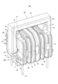
図2から図4のいずれかに示すように、ボビン10は、例えば、ボビン10の軸方向における両端部にそれぞれ配置されているフランジ状の端部壁14と、ボビン10の軸方向における中央部に配置されているフランジ状の中央壁16と、端部壁14と中央壁16との間に配置されているフランジ状の仕切壁13と、を備えている。
図4に示すように、例えば、ボビン10における仕切壁13と端部壁14との間の部分、及び、ボビン10における仕切壁13と中央壁16との間の部分は、線材40(図6)が巻回される被巻回部12を構成している。
As shown in any of FIGS. 2 to 4, the
As shown in FIG. 4, for example, a portion of the
図1に示すように、第1部材10a及び第2部材10bの各々は、仕切壁構成リブ13aと、一対の端部壁構成部14aと、中央壁構成部16aと、を備えている。
第1部材10aと第2部材10bとが相互に組み付けられてボビン10が構成された状態では、第1部材10aの仕切壁構成リブ13aと第2部材10bの仕切壁構成リブ13aとにより仕切壁13が構成され、第1部材10aの端部壁構成部14aと第2部材10bの端部壁構成部14aとにより端部壁14が構成され、第1部材10aの中央壁構成部16aと第2部材10bの中央壁構成部16aとにより中央壁16が構成される。
As shown in FIG. 1, each of the
When the
例えば、中央壁構成部16aには、係合爪部161、係合凸部162、ボス17及び嵌入孔18が形成されている。
第1部材10aと第2部材10bとが相互に組み付けられた状態では、第1部材10aの係合爪部161が第2部材10bの係合凸部162に対して係合するとともに、第2部材10bの係合爪部161が第1部材10aの係合凸部162に対して係合する。
更に、第1部材10aと第2部材10bとが相互に組み付けられた状態では、第1部材10aのボス17が第2部材10bの嵌入孔18に対して嵌入するとともに、第2部材10bのボス17が第1部材10aの嵌入孔18に対して嵌入する。
For example, an engaging
When the
Further, when the
更に、端部壁構成部14aには、突出部15と回転規制部19とが形成されている。
第1部材10aの2つの端部壁構成部14aの各々に突起部15が形成されており、これら突起部15は端部壁構成部14aの上面から上方に突出している
また、第2部材10bの2つの端部壁構成部14aの各々に突起部15が形成されており、これら突起部15は端部壁構成部14aの下面から下方に突出している
突出部15の先端面は、平坦面15aとなっている。
回転規制部19は、第1部材10a及び第2部材10bの軸方向における端面に形成されている。
回転規制部19は、例えば、L字状のリブである。すなわち、回転規制部19は、上下に延在する第1リブ19aと、水平に延在する第2リブ19bと、を含んで構成されている。
Further, a protruding
A
The
The
図7に示すように、第1部材10aは、第2部材10bに対する対向面から第2部材10b側に起立しているとともに第1凹部11aの一部分を構成する第1起立片21と、第1凹部11aを間に挟んで第1起立片21と対向している第3凹部23と、を有する。
また、第2部材10bは、第1部材10aに対する対向面から第1部材10a側に起立しているとともに第2凹部11bの一部分を構成する第2起立片22と、第2凹部11bを間に挟んで第2起立片22と対向している第4凹部24と、を有する。
そして、組立状態では、第1起立片21が第4凹部24に対して嵌合するとともに、第2起立片22が第3凹部23に対して嵌合する(図8参照)。
As shown in FIG. 7, the
Further, the
In the assembled state, the
更に、第1部材10aは、第1凹部11a及び第3凹部23を間に挟んで第1起立片21と対向する位置に第3起立片25を有している。すなわち、第3起立片25の側面に第3凹部23が形成されている。
加えて、第1部材10aは、第1起立片21を基準として第3起立片25側とは反対側に隣接する位置に、第5凹部27を有している。
同様に、第2部材10bは、第2凹部11b及び第4凹部24を間に挟んで第2起立片22と対向する位置に第4起立片26を有している。すなわち、第4起立片26の側面に第4凹部24が形成されている。
加えて、第2部材10bは、第2起立片22を基準として第4起立片26側とは反対側に隣接する位置に、第6凹部28を有している。
そして、組立状態では、第3起立片25が第6凹部28に対して嵌合するとともに、第4起立片26が第5凹部27に対して嵌合する(図8参照)。
Further, the
In addition, the
Similarly, the
In addition, the
In the assembled state, the third
なお、第1起立片21及び第3凹部23は、例えば、第1部材10aの軸方向における全域に亘って延在している。
同様に、第2起立片22及び第4凹部24は、例えば、第2部材10bの軸方向における全域に亘って延在している。
また、第3起立片25及び第5凹部27は、例えば、第1部材10aの軸方向における全域に亘って延在している。
同様に、第4起立片26及び第6凹部28は、例えば、第2部材10bの軸方向における全域に亘って延在している。
Note that the
Similarly, the
Further, the third
Similarly, the
コア30は、上述した第1延伸部31及び第2延伸部32の他に、第3延伸部33及び第4延伸部34を備えて構成されている。
第1延伸部31、第2延伸部32、第3延伸部33及び第4延伸部34の各々は、棒状の部分である。
第1延伸部31と第2延伸部32とは、例えば互いに平行に延在している。
また、第3延伸部33と第4延伸部34とは、例えば互いに平行に延在している。
また、例えば、第1延伸部31及び第2延伸部32に対して、第3延伸部33及び第4延伸部34が直交している。
第1延伸部31、第2延伸部32、第3延伸部33及び第4延伸部34の各々の断面形状は、例えば、四角形状となっている。より詳細には、本実施形態の場合、第1延伸部31、第2延伸部32、第3延伸部33及び第4延伸部34の各々の断面形状は、角部が面取り形状とされた矩形状となっている。
The
Each of the first extending
The first extending
Further, the third extending
Further, for example, the
The cross-sectional shape of each of the first extending
ここで、貫通孔11の断面形状は、第1延伸部31の断面形状と対応する四角形状となっている。
Here, the cross-sectional shape of the through
第2部材10bには、端子ピン41が設けられている。本実施形態の場合、例えば、ボビン10には、2本の線材40が別個に巻回されるようになっており、第2部材10bには4本の端子ピン41が設けられている。
A
なお、本実施形態に係るフィルタ部品100及びフィルタ部品組立用キット200のボビン10は、特許文献1のフィルタ部品が備えるようなギアに相当する構成を備えていない。よって、フィルタ部品100の小型化が可能である。
Note that the
次に、図5(a)、図5(b)、図5(c)、図5(d)及び図6を用いて、本実施形態に係るフィルタ部品の製造方法を説明する。 Next, a method for manufacturing a filter component according to this embodiment will be described using FIGS. 5(a), 5(b), 5(c), 5(d), and 6.
先ず、図5(a)に示すように、コア30を第1部材10aに対して横倒しにして、第1部材10aの第1凹部11a内にコア30の第1延伸部31を配置する。
First, as shown in FIG. 5A, the
次に、図5(b)及び図5(c)に示すように、コア30に第1部材10aをくぐらせるようにして、第1延伸部31の長手軸周りにおいて第1部材10aに対してコア30を回転させる。その結果、図5(c)に示すように、コア30の第1延伸部31と第2延伸部32との間に第1部材10aが位置する状態にする。
Next, as shown in FIGS. 5(b) and 5(c), the
図5(a)の状態からコア30を90度回転させて、図5(c)の状態とした段階で、コア30の第3延伸部33及び第4延伸部34が第1部材10aの両端面の回転規制部19の第1リブ19aに当接し、コア30の回転が規制される。
When the
次に、図5(d)に示すように、第1部材10aに対して第2部材10bを組み付ける。これにより、第1部材10aと第2部材10bとによりボビン10が構成されるとともに、第1部材10aの第1凹部11aと第2部材10bの第2凹部11bとにより貫通孔11が構成される。
また、貫通孔11に第1延伸部31が挿通された状態となる。
Next, as shown in FIG. 5(d), the
Further, the first extending
更に、図5(d)に示すように、コア30をボビン10に対して相対的に上昇させる(第1延伸部31を貫通孔11内で第2延伸部32側に移動させる)ことによって第2延伸部32とボビン10との間隔を広げた状態で、ボビン10と第2延伸部32との間を通してボビン10の周囲に線材40を巻回する。すなわち、ボビン10の被巻回部12に線材40を巻回する。
ここで、第2延伸部32とボビン10との間隔を広げた状態で線材40を巻回するので、ギアを用いることなく、ボビン10に対して線材40を巻回する工程を容易に行うことができる。
Furthermore, as shown in FIG. 5(d), the
Here, since the
なお、第1部材10aと第2部材10bとは相互に接着固定しても良いし、しなくてもよい(第1部材10aと第2部材10bとが線材40によって拘束されているだけであってもよい)。
Note that the
次に、コア30をボビン10に対して相対的に下降させる(第1延伸部31を貫通孔11内で第2延伸部32側とは反対側に移動させる)。
次に、第1延伸部31を貫通孔11に対して接着固定する。
Next, the
Next, the first extending
ここで、第1延伸部31の長手軸周りにおいてボビン10に対するコア30の回転が規制されているため、ボビン10に線材40を巻回する工程中にボビン10によってコア30を安定的に保持することができるとともに、ボビン10に線材40を巻回した後では、コア30をボビン10に対して正確に位置決めした状態で、第1延伸部31を貫通孔11に接着することができる。
Here, since the rotation of the core 30 with respect to the
なお、ボビン10には、例えば2本の線材40を巻回する。すなわち、中央壁16を境とする一方の側に1本の線材40を巻回し、中央壁16を境とする他方の側にもう1本の線材40を巻回する。
そして、各線材40の両端をそれぞれ端子ピン41に対して電気的に接続する。
なお、端子ピン41は、ボビン10に線材40を巻回するよりも前に第2部材10bに予め取り付けられていてもよいし、ボビン10に線材40を巻回したあとで第2部材10bに取り付けられてもよいし、ボビン10に線材40を巻回しながら第2部材10bに取り付けられてもよい。
Note that, for example, two
Then, both ends of each
Note that the
こうして、図6に示すフィルタ部品100が得られる。
このように、本実施形態に係るフィルタ部品100は、本実施形態に係るフィルタ部品組立用キット200を用いて組み立てられたフィルタ部品100であって、組立状態の第1部材10a、第2部材10b及びコア30と、ボビン10の周囲に巻回された線材40と、を備える。
そして、第1延伸部31が貫通孔11に対して固定されている。
In this way, the
As described above, the
The first extending
また、本実施形態に係るフィルタ部品の製造方法は、第1部材10aと第2部材10bとが相互に組み付けられることにより貫通孔11を有する形態とされたボビン10と、全体が一体形成された四角形状の枠体状のコア30と、ボビン10の周囲に巻回された線材40と、を備えるフィルタ部品100を製造する方法であって、以下の工程を有する。
第1部材10a、第2部材10b及びコア30を相互に組み立てて、第1延伸部31が貫通孔11を貫通して配置されるとともに第2延伸部32が貫通孔11の外部に配置された状態にする組立工程。
第1延伸部31を貫通孔11内で第2延伸部32側(本実施形態の場合、上側)に移動させることによって第2延伸部32とボビン10との間隔を広げた状態で、ボビン10と第2延伸部32との間を通してボビン10の周囲に線材40を巻回する工程。
第1延伸部31を貫通孔11内で第2延伸部32側とは反対側(本実施形態の場合、下側)に移動させる工程。
In addition, the method for manufacturing a filter component according to the present embodiment is such that the
The
By moving the first extending
A step of moving the first extending
また、上記組立工程は、第1凹部11aに第1延伸部31を配置する工程と、第1延伸部31の長手軸周りにおいて第1部材10aに対してコア30を回転させて第1延伸部31と第2延伸部32との間に第1部材10aが位置する状態にする工程と、第1部材10aと第2部材10bとを相互に組み付けて第1延伸部31が貫通孔11を貫通して配置されるとともに第2延伸部32が貫通孔11の外部に配置された状態にする工程と、を含む。
Further, the above assembly step includes a step of arranging the first extending
更に、本実施形態に係るフィルタ部品の製造方法は、第1延伸部31を貫通孔11内で第2延伸部32側とは反対側に移動させた状態で、第1延伸部31を貫通孔11に対して接着固定する工程を備える。
Furthermore, in the method for manufacturing a filter component according to the present embodiment, the first extending
なお、上記のように、第1凹部11aに第1延伸部31が配置された状態で、第1延伸部31の長手軸周りにおいて第1部材10aに対してコア30が回転可能となっている。
例えば、第1凹部11aの底面(図5(a)、図5(b)及び図5(c)では第1凹部11aの天面)に対して常に第1延伸部31が接した状態で、第1延伸部31の長手軸周りにおいて第1部材10aに対してコア30が回転可能となっている。
Note that, as described above, the
For example, with the first extending
また、第1部材10aは、当該第1部材10aに対して第2部材10bを組み付ける際の回転角度において第1部材10aに対するコア30の回転を規制する回転規制部19を、第1凹部11aの外部に有する。
The
ここで、図5(d)のように第1部材10a、第2部材10b及びコア30が相互に組み立てられた状態では、第1延伸部31の長手軸周りにおいてボビン10に対するコア30の回転が規制される。
本実施形態の場合、図8に示すように、第1延伸部31の長手方向に対して直交する断面において、第1延伸部31の外接円36が、貫通孔11からはみ出す。これにより、ボビン10に対してコア30を回転させようとすると、第1延伸部31の外周面と貫通孔11の内周面とが干渉するため、ボビン10に対するコア30の回転が規制される。
Here, in a state where the
In the case of this embodiment, as shown in FIG. 8 , the circumscribed
より詳細には、第1延伸部31の長手軸周りにおいてボビン10に対してコア30を回転させようとすると、第1延伸部31と第1起立片21及び第2起立片22とが干渉してボビン10に対するコア30の回転が規制される。
More specifically, when trying to rotate the core 30 with respect to the
一方、図9に示すように、第1部材10aの第1凹部11aに第1延伸部31を配置してコア30を第1部材10aに対して回転させる際(図5(a)から図5(c)の工程)には、第1延伸部31の角部が第3凹部23に入り込むことができるため、コア30を第1部材10aに対して回転させることができる。
つまり、第1部材10aに第2部材10bを組み付ける前の段階では、第3凹部23内に第2起立片22が入り込んでいないため、第1部材10aに対するコア30の回転が許容される。
On the other hand, as shown in FIG. 9, when the first extending
In other words, before the
また、図5(d)のように第1部材10a、第2部材10b及びコア30が相互に組み立てられた状態において、貫通孔11の上下寸法は、第1延伸部31の上下寸法よりも大きい。
これにより、第1延伸部31が貫通孔11内において上下に移動可能となっている。すなわち、コア30がボビン10に対して上下に移動可能である。
ここで、ボビン10に対してコア30が上下に移動可能な長さ(第1移動長さ)は、ボビン10に対してコア30が上記直交方向(図3における左右方向)に移動可能な長さ(第2移動長さ)よりも大きい。
すなわち、第1延伸部31の外周面と貫通孔11の内周面とのクリアランスは、上下方向におけるクリアランスの方が、上記直交方向(図3における左右方向)におけるクリアランスよりも大きい。
Further, in a state where the
This allows the first extending
Here, the length by which the
That is, the clearance between the outer circumferential surface of the first extending
なお、第1延伸部31と第2延伸部32との対向方向(図3における上下方向)と第1延伸部31の長手方向(図3における奥行き方向)との双方に対する直交方向(図3における左右方向)における第1延伸部31の幅寸法が、上記対向方向における貫通孔11の寸法よりも大きくても良い。すなわち、このようにしたことによって、ボビン10に対するコア30の回転が規制されていてもよい。
更に、上記直交方向における貫通孔11の幅寸法が、上記対向方向における第1延伸部31の寸法よりも大きい。これにより、上記のように、コア30を第1部材10aに対して横倒しにして、第1部材10aの第1凹部11a内にコア30の第1延伸部31を配置することができる。
Note that the direction perpendicular to both the opposing direction between the
Furthermore, the width dimension of the through
ここで、本実施形態の場合、上記のように、第1部材10aと第2部材10bとの組み付け方向と、上記対向方向とが一致しており、組立状態において、第1延伸部31と第2延伸部32との間に第1部材10aが配置される。
そして、図3に示す距離Lよりも距離Dの方が長いことが好ましい。
すなわち、上記直交方向(図3における左右方向)における貫通孔11の中心位置にて、上記対向方向(図3における上下方向)における第1部材10aの寸法と貫通孔11の寸法との和をLとする。言い換えれば、図3において、第1部材10aの突出部15の平坦面15aから、貫通孔11の底面(第2部材10bの第2凹部11bの底面)までの距離がLとなる。一方、第2延伸部32における第1延伸部31に対する対向面(図3における第2延伸部32の下面)と第1延伸部31における第2延伸部32側とは反対側を向く反対面(図3における第1延伸部31の下面)との距離をDとすると、L<Dを満たすことが好ましい。
このような構成とすることにより、コア30とボビン10とを好適に組立状態にすることができる。
Here, in the case of the present embodiment, as described above, the direction in which the
Further, it is preferable that the distance D is longer than the distance L shown in FIG.
That is, at the center position of the through
With such a configuration, the
更に、図3に示す距離Lよりも距離Rの方が長いことが好ましい。
距離Rは、ボビン10を軸方向に視たときに、貫通孔11の底面における上記直交方向(図3における左右方向)での中心位置と、ボビン10において当該中心位置から最も遠い位置と、の距離である。
このような構成とすることによっても、第1延伸部31の長手軸周りにおいてボビン10に対するコア30の回転が規制される。
Furthermore, it is preferable that the distance R is longer than the distance L shown in FIG.
The distance R is defined as the distance between the center position of the bottom surface of the through
With such a configuration, rotation of the core 30 with respect to the
また、上記組立状態において、ボビン10において第2延伸部32と対向する第2延伸部側対向面(図4におけるボビン10の上面)において、第1延伸部31の長手方向における両端部のうちの少なくとも一方(本実施形態の場合、両方)に、第2延伸部32側に突出した突出部15が形成されている。
そして、第2延伸部側対向面の両端部どうしの間の中間部と第2延伸部32との距離は、第2延伸部32と突出部15との距離よりも長い。
このため、第2延伸部32とボビン10との間に線材40を通してボビン10に線材40を巻回する作業を、より容易に行うことができる。
しかも、ボビン10が突出部15を有するため、図5(c)のように第1部材10aに対して30を位置合わせした状態において、ボビン10によってコア30を安定的に保持することができる。特に、突出部15の先端面が平坦面15aであるため、ボビン10によってコア30をより安定的に保持することができる。
In addition, in the assembled state, on the second stretching part side facing surface of the
The distance between the second extending
Therefore, the work of passing the
Moreover, since the
以上のような第1実施形態によれば、上記組立状態において、第1延伸部31が貫通孔11内において第1部材10aと第2部材10bとの対向方向に移動可能であるため、ボビン10に線材40を巻回する際に、第2延伸部32とボビン10との間隔を広げることができる。よって、ギアを用いることなく、ボビン10に対する線材の巻回を容易に行うことができるので、フィルタ部品100にはギアが不要であり、フィルタ部品100の小型化が可能となる。
特に、上記第1移動長さが上記第2移動長さよりも大きいため、第2延伸部32とボビン10との間隔をより十分に広げることができる。
しかも、上記組立状態において、第1延伸部31の長手軸周りにおいてボビン10に対するコア30の回転が規制されるため、ボビン10に線材40を巻回する工程中にボビン10によってコア30を安定的に保持することができるとともに、ボビン10に線材40を巻回した後で、コア30をボビン10に対して正確に位置決めした状態で第1延伸部31を貫通孔11に接着することができる。
According to the first embodiment as described above, in the assembled state, the first extending
Particularly, since the first moving length is larger than the second moving length, the distance between the second extending
Moreover, in the assembled state, the rotation of the core 30 with respect to the
<第1実施形態の変形例1>
次に、図14を用いて第1実施形態の変形例1を説明する。
上記の第1実施形態では、第1部材10aと第2部材10bとの組付け方向と、コア30の第1延伸部31と第2延伸部32との対向方向とが一致している例を説明したが、本変形例の場合、第1部材10aと第2部材10bとの組付け方向と、コア30の第1延伸部31と第2延伸部32との対向方向とが互いに交差(例えば直交)している。
すなわち、本変形例の場合、上記対向方向が上下方向であり、上記対向方向が水平方向となっている。
この場合、第1延伸部31が貫通孔11内において水平方向に移動可能な第1移動長さが、第1延伸部31が貫通孔11内において上下方向に移動可能な第2移動長さよりも大きい。
本変形例の場合、上記の第1実施形態と比べて、フィルタ部品の水平方向寸法が大きくなる代わりに、フィルタ部品の高さ寸法を小さくすることができる。
<Modification 1 of the first embodiment>
Next, modification 1 of the first embodiment will be described using FIG. 14.
In the first embodiment described above, the example in which the direction in which the
That is, in the case of this modification, the facing direction is the vertical direction, and the facing direction is the horizontal direction.
In this case, the first moving length by which the first extending
In the case of this modification, compared to the first embodiment described above, the horizontal dimension of the filter component becomes larger, but the height dimension of the filter component can be reduced.
<第1実施形態の変形例2>
次に、図15を用いて第1実施形態の変形例2を説明する。
本変形例の場合、図15に示すように、上記直交方向における第1延伸部31の幅寸法よりも、上記直交方向における第2延伸部32、第3延伸部33及び第4延伸部34の幅寸法の方が大きい。すなわち、第1延伸部31の両端部と第3延伸部33及び第4延伸部34との境界部には、段差部35が形成されている。
これにより、上記対向方向における第2延伸部32の厚みを抑制できるため、第1実施形態と比べて、フィルタ部品100の高さ寸法を小さくすることができる。
また、ボビン10の軸方向において第3延伸部33及び第4延伸部34の厚みを抑制できるため、ボビン10の軸方向におけるフィルタ部品100の寸法についても、第1実施形態と比べて小さくすることができる。
<Modification 2 of the first embodiment>
Next, a second modification of the first embodiment will be described using FIG. 15.
In the case of this modification, as shown in FIG. 15, the width of the second stretched
Thereby, since the thickness of the second extending
Furthermore, since the thickness of the third stretched
<第1実施形態の変形例3>
次に、図16を用いて第1実施形態の変形例3を説明する。
図15に示す変形例2では、段差部35が、第4延伸部34及び第3延伸部33において面取り形状となっている部分よりも更に深い段差となっているのに対し、本変形例の場合、段差部35は、第4延伸部34及び第3延伸部33において面取り形状となっている部分に相当する深さの段差に形成されている。
本変形例の場合も、上記の第1実施形態と比べて、フィルタ部品100の高さ寸法を小さくすることができるとともに、ボビン10の軸方向におけるフィルタ部品100の寸法を小さくすることができる。
<Variation 3 of the first embodiment>
Next, a third modification of the first embodiment will be described using FIG. 16.
In the second modification shown in FIG. 15, the stepped
Also in the case of this modification, the height dimension of the
〔第2の実施形態〕
次に、図10から図13を用いて第2実施形態を説明する。
[Second embodiment]
Next, a second embodiment will be described using FIGS. 10 to 13.
上記の第1実施形態では、ボビン10を構成する第1部材10a及び第2部材10bの組付け方向が上下方向であるのに対して、本実施形態の場合、第1部材10a及び第2部材10bの組付け方向が横方向である。
ただし、コア30は、第1実施形態と同様に、第3延伸部33及び第4延伸部34が上下に延在する姿勢で配置される。
したがって、第1延伸部31と第2延伸部32との対向方向と、第1部材10a及び第2部材10bの組付け方向(分割方向)とが互いに交差(例えば直交)している。
よって、図10に示すように、第1部材10aの第1凹部11aと、第2部材10bの第2凹部11bは、それぞれ横方向に向けて開口している。
In the first embodiment described above, the
However, similarly to the first embodiment, the
Therefore, the direction in which the first extending
Therefore, as shown in FIG. 10, the
図10に示すように、本実施形態の場合、第2部材10bにおいて第1部材10aと対向する面において、第2凹部11bよりも上側の部位には、第1部材10a側に向けてそれぞれ突出している第1上部突起部51及び第2上部突起部52が形成されている。
また、第2部材10bにおいて第1部材10aと対向する面において、第2凹部11bよりも下側の部位には、第1部材10a側に向けてそれぞれ突出している第1下部突起部53及び第2下部突起部54が形成されている。
同様に、第1部材10aにおいて第2部材10bと対向する面にも、第1上部突起部51、第2上部突起部52、第1下部突起部53及び第2下部突起部54が形成されている。
As shown in FIG. 10, in the case of the present embodiment, on the surface of the
In addition, on the surface of the
Similarly, a first
第1上部突起部51と第2上部突起部52とは、相互に対向する位置に配置されており、第1部材10aと第2部材10bとが相互に組み付けられた状態では、第1上部突起部51と第2上部突起部52とが嵌合するようになっている。
また、第1下部突起部53と第2下部突起部54とは、相互に対向する位置に配置されており、第1部材10aと第2部材10bとが相互に組み付けられた状態では、第1下部突起部53と第2下部突起部54とが嵌合するようになっている。
The first
Further, the first
本実施形態の場合も、第1部材10a、第2部材10b及びコア30が相互に組み立てられた組立状態(図11、図12、図13)において、コア30がボビン10に対して相対的に上下動できるようになっている。そして、第1延伸部31が貫通孔11内において相対的に上下動可能な第1移動長さが、第1延伸部31が貫通孔11内において相対的に横方向に移動可能な第2移動長さよりも大きい。
Also in the case of this embodiment, in the assembled state in which the
ここで、図13に示すように、貫通孔11の軸方向におけるボビン10の両端面のうち、一方の端面には、第3延伸部33と嵌合する嵌合凹部57が形成されており、他方の端面には、第4延伸部34と嵌合する嵌合凹部57が形成されている。
ただし、本発明は、この例に限らず、貫通孔11の軸方向におけるボビン10の両端面のうち少なくとも一方に、第3延伸部33又は第4延伸部34と嵌合する嵌合凹部57が形成されていても良い。
Here, as shown in FIG. 13, a
However, the present invention is not limited to this example, and the
すなわち、コア30は、第1延伸部31及び第2延伸部32に対して交差する方向にそれぞれ延在しているとともに互いに並列に延在している第3延伸部33及び第4延伸部34を有し、貫通孔11の軸方向におけるボビン10の両端面のうちの少なくとも一方は、第3延伸部33又は第4延伸部34と嵌合する嵌合凹部57を有する。
これにより、貫通孔11の軸方向におけるフィルタ部品の寸法を小さくすることができる。
That is, the
Thereby, the size of the filter component in the axial direction of the through
より詳細には、図10に示すように、第1部材10aの第1上部突起部51には凹部57aが形成されており、第2部材10bの第2上部突起部52には凹部57bが形成されており、第1部材10aと第2部材10bとが組み付けられて凹部57aと凹部57bとが合わさることにより、一方の嵌合凹部57(図13)が構成されており、当該嵌合凹部57に対して第3延伸部33における内面側の部分が嵌合している。
More specifically, as shown in FIG. 10, a
また、図示は省略するが、第1部材10aの第2上部突起部52には凹部57bが形成されており、第2部材10bの第1上部突起部51には凹部57aが形成されており、第1部材10aと第2部材10bとが組み付けられて凹部57aと凹部57bとが合わさることにより、他方の嵌合凹部57(図13)が構成されており、当該嵌合凹部57に対して第4延伸部34における内面側の部分が嵌合している。
Although not shown, a
このように、本実施形態の場合、第1部材10aと第2部材10bとの組み付け方向と上記対向方向とが互いに直交しており、第1部材10aに形成された第1嵌合凹部構成部(凹部57a、57b)と第2部材10bに形成された第2嵌合凹部構成部(57a、57b)とにより嵌合凹部57が構成される。
As described above, in the case of the present embodiment, the direction in which the
以上、図面を参照して各実施形態を説明したが、これらは本発明の例示であり、上記以外の様々な構成を採用することもできる。また、上記の各実施形態は、本発明の主旨を逸脱しない範囲で、適宜に組み合わせることができる。 Although each embodiment has been described above with reference to the drawings, these are merely examples of the present invention, and various configurations other than those described above may also be adopted. Furthermore, the above-described embodiments can be combined as appropriate without departing from the spirit of the present invention.
本実施形態は以下の技術思想を包含する。
(1)
第1部材と第2部材とが相互に組み付けられることにより貫通孔を有する形態とされたボビンと、全体が一体形成された四角形状の枠体状のコアと、前記ボビンの周囲に巻回された線材と、を備えるフィルタ部品の組み立てに用いられるフィルタ部品組立用キットであって、
前記第1部材と、
前記第2部材と、
前記コアと、
を備え、
前記コアは、互いに並列に延在している第1延伸部及び第2延伸部を有し、
前記第1部材、前記第2部材及び前記コアが相互に組み立てられて、前記第1延伸部が前記貫通孔を貫通して配置されるとともに前記第2延伸部が前記貫通孔の外部に配置された組立状態において、
前記第1延伸部の長手軸周りにおいて前記ボビンに対する前記コアの回転が規制されるとともに、前記第1延伸部が前記貫通孔内において前記第1延伸部と前記第2延伸部との対向方向に移動可能であり、且つ、前記第1延伸部が前記貫通孔内において前記対向方向に移動可能な第1移動長さが、前記第1延伸部が前記貫通孔内において前記対向方向と前記第1延伸部の長手方向との双方に対する直交方向に移動可能な第2移動長さよりも大きいフィルタ部品組立用キット。
(2)
前記第1延伸部の断面形状が四角形状であり、
前記貫通孔の断面形状が四角形状であり、
前記直交方向における前記第1延伸部の幅寸法が、前記対向方向における前記貫通孔の寸法よりも大きく、
前記直交方向における前記貫通孔の幅寸法が、前記対向方向における前記第1延伸部の寸法よりも大きい(1)に記載のフィルタ部品組立用キット。
(3)
前記第1延伸部の長手方向に対して直交する断面において、前記第1延伸部の外接円が、前記貫通孔からはみ出す(1)又は(2)に記載のフィルタ部品組立用キット。
(4)
前記第1部材は、前記貫通孔の一部分を構成する第1凹部を有し、
前記第2部材は、前記第1凹部とともに前記貫通孔を構成する第2凹部を有し、
前記第1凹部に前記第1延伸部が配置された状態で、前記第1延伸部の長手軸周りにおいて前記第1部材に対して前記コアが回転可能である(1)から(3)のいずれか一項に記載のフィルタ部品組立用キット。
(5)
前記第1部材は、当該第1部材に対して前記第2部材を組み付ける際の回転角度において前記第1部材に対する前記コアの回転を規制する回転規制部を、前記第1凹部の外部に有する(4)に記載のフィルタ部品組立用キット。
(6)
前記第1部材は、前記第2部材に対する対向面から前記第2部材側に起立しているとともに前記第1凹部の一部分を構成する第1起立片と、前記第1凹部を間に挟んで前記第1起立片と対向している第3凹部と、を有し、
前記第2部材は、前記第1部材に対する対向面から前記第1部材側に起立しているとともに前記第2凹部の一部分を構成する第2起立片と、前記第2凹部を間に挟んで前記第2起立片と対向している第4凹部と、を有し、
前記組立状態では、前記第1起立片が前記第4凹部に対して嵌合するとともに、前記第2起立片が前記第3凹部に対して嵌合し、前記第1延伸部の長手軸周りにおいて前記ボビンに対して前記コアを回転させようとすると、前記第1延伸部と前記第1起立片及び前記第2起立片とが干渉して前記ボビンに対する前記コアの回転が規制される(4)又は(5)に記載のフィルタ部品組立用キット。
(7)
前記第1部材と前記第2部材との組み付け方向と前記対向方向とが一致しており、
前記組立状態において、前記第1延伸部と前記第2延伸部との間に前記第1部材が配置され、前記直交方向における前記貫通孔の中心位置にて、前記対向方向における前記第1部材の寸法と前記貫通孔の寸法との和をLとし、前記第2延伸部における前記第1延伸部に対する対向面と前記第1延伸部における前記第2延伸部側とは反対側を向く反対面との距離をDとすると、
L<Dを満たす(1)から(6)のいずれか一項に記載のフィルタ部品組立用キット。
(8)
前記組立状態において、
前記ボビンにおいて前記第2延伸部と対向する第2延伸部側対向面において、前記第1延伸部の長手方向における両端部のうちの少なくとも一方に、前記第2延伸部側に突出した突出部が形成され、
前記第2延伸部側対向面の前記両端部どうしの間の中間部と前記第2延伸部との距離は、前記第2延伸部と前記突出部との距離よりも長い(1)から(7)のいずれか一項に記載のフィルタ部品組立用キット。
(9)
前記コアは、前記第1延伸部及び前記第2延伸部に対して交差する方向にそれぞれ延在しているとともに互いに並列に延在している第3延伸部及び第4延伸部を有し、
前記貫通孔の軸方向における前記ボビンの両端面のうちの少なくとも一方は、前記第3延伸部又は前記第4延伸部と嵌合する嵌合凹部を有する(1)から(8)のいずれか一項に記載のフィルタ部品組立用キット。
(10)
前記第1部材と前記第2部材との組み付け方向と前記対向方向とが互いに直交しており、
前記第1部材に形成された第1嵌合凹部構成部と前記第2部材に形成された第2嵌合凹部構成部とにより前記嵌合凹部が構成される(9)に記載のフィルタ部品組立用キット。
(11)
(1)から(10)のいずれか一項に記載のフィルタ部品組立用キットを用いて組み立てられたフィルタ部品であって、
前記組立状態の前記第1部材、前記第2部材及び前記コアと、
前記ボビンの周囲に巻回された前記線材と、
を備えるフィルタ部品。
(12)
前記第1延伸部が前記貫通孔に対して固定されている(11)に記載のフィルタ部品。
(13)
第1部材と第2部材とが相互に組み付けられることにより貫通孔を有する形態とされたボビンと、全体が一体形成された四角形状の枠体状のコアと、前記ボビンの周囲に巻回された線材と、を備えるフィルタ部品を製造する方法であって、
前記コアは、互いに並列に延在している第1延伸部及び第2延伸部を有するものであり、
当該方法は、
前記第1部材、前記第2部材及び前記コアを相互に組み立てて、前記第1延伸部が前記貫通孔を貫通して配置されるとともに前記第2延伸部が前記貫通孔の外部に配置された状態にする組立工程と、
前記第1延伸部を前記貫通孔内で前記第2延伸部側に移動させることによって前記第2延伸部と前記ボビンとの間隔を広げた状態で、前記ボビンと前記第2延伸部との間を通して前記ボビンの周囲に線材を巻回する工程と、
前記第1延伸部を前記貫通孔内で前記第2延伸部側とは反対側に移動させる工程と、
を備えるフィルタ部品の製造方法。
(14)
前記第1部材は、前記貫通孔の一部分を構成する第1凹部を有するものであり、
前記第2部材は、前記第1凹部とともに前記貫通孔を構成する第2凹部を有するものであり、
前記組立工程は、
前記第1凹部に前記第1延伸部を配置する工程と、
前記第1延伸部の長手軸周りにおいて前記第1部材に対して前記コアを回転させて、前記第1延伸部と前記第2延伸部との間に前記第1部材が位置する状態にする工程と、
前記第1部材と前記第2部材とを相互に組み付けて、前記第1延伸部が前記貫通孔を貫通して配置されるとともに前記第2延伸部が前記貫通孔の外部に配置された状態にする工程と、
を含む(13)に記載のフィルタ部品の製造方法。
(15)
前記第1延伸部を前記貫通孔内で前記第2延伸部側とは反対側に移動させた状態で、前記第1延伸部を前記貫通孔に対して接着固定する工程を備える(13)又は(14)に記載のフィルタ部品の製造方法。
This embodiment includes the following technical ideas.
(1)
A bobbin having a through hole formed by assembling a first member and a second member with each other, a rectangular frame-shaped core integrally formed as a whole, and a bobbin wound around the bobbin. A filter parts assembly kit used for assembling filter parts, comprising:
the first member;
the second member;
The core;
Equipped with
The core has a first extending portion and a second extending portion extending in parallel to each other,
The first member, the second member, and the core are assembled with each other, and the first extending portion is disposed passing through the through hole, and the second extending portion is disposed outside the through hole. In the assembled state,
Rotation of the core relative to the bobbin is regulated around the longitudinal axis of the first elongated section, and the first elongated section is arranged in a direction opposite to the first elongated section and the second elongated section within the through hole. and a first moving length by which the first extending portion is movable in the opposing direction within the through hole is such that the first moving length is such that the first extending portion is movable within the through hole in the opposing direction and the first moving length. A kit for assembling filter parts that is larger than a second movement length that is movable in a direction orthogonal to both the longitudinal direction of the extension part.
(2)
The cross-sectional shape of the first extending portion is a square shape,
The cross-sectional shape of the through hole is square,
A width dimension of the first extending portion in the orthogonal direction is larger than a dimension of the through hole in the opposing direction,
The filter component assembly kit according to (1), wherein the width of the through hole in the orthogonal direction is larger than the width of the first extending portion in the opposing direction.
(3)
The filter component assembly kit according to (1) or (2), in which a circumscribed circle of the first extending portion protrudes from the through hole in a cross section perpendicular to the longitudinal direction of the first extending portion.
(4)
The first member has a first recess that constitutes a part of the through hole,
The second member has a second recess that forms the through hole together with the first recess,
Any one of (1) to (3), wherein the core is rotatable with respect to the first member around the longitudinal axis of the first extension part with the first extension part disposed in the first recess. The filter parts assembly kit described in item (1) above.
(5)
The first member has a rotation restricting portion outside the first recess that restricts rotation of the core relative to the first member at a rotation angle when the second member is assembled to the first member. Filter parts assembly kit described in 4).
(6)
The first member includes a first upright piece that stands up on the second member side from a surface facing the second member and forms a part of the first recess, and a first upright piece with the first recess in between. a third recess facing the first upright piece;
The second member includes a second upright piece that stands up on the first member side from a surface facing the first member and forms a part of the second recess, and a second upright piece with the second recess in between. a fourth recess facing the second upright piece;
In the assembled state, the first upright piece fits into the fourth recess, the second upright piece fits into the third recess, and the first upright piece fits around the longitudinal axis of the first extending part. When an attempt is made to rotate the core with respect to the bobbin, the first extending portion interferes with the first upright piece and the second upright piece, and rotation of the core with respect to the bobbin is restricted (4) Or the filter parts assembly kit described in (5).
(7)
The assembly direction of the first member and the second member is the same as the opposing direction,
In the assembled state, the first member is disposed between the first extending part and the second extending part, and the first member in the opposing direction is disposed at the center position of the through hole in the orthogonal direction. The sum of the dimensions and the dimensions of the through hole is L, and a surface of the second stretching section facing the first stretching section and an opposite surface facing the opposite side of the second stretching section of the first stretching section. Let D be the distance of
The filter parts assembly kit according to any one of (1) to (6), satisfying L<D.
(8)
In the assembled state,
On the second stretching part side facing surface of the bobbin that faces the second stretching part, at least one of both ends in the longitudinal direction of the first stretching part has a protruding part that projects toward the second stretching part. formed,
The distance between the intermediate portion between the two end portions of the second extending portion side facing surface and the second extending portion is longer than the distance between the second extending portion and the protruding portion (1) to (7). ) A kit for assembling filter parts as described in any one of the above.
(9)
The core has a third stretching part and a fourth stretching part extending in a direction crossing the first stretching part and the second stretching part, respectively, and extending in parallel to each other,
At least one of both end surfaces of the bobbin in the axial direction of the through hole has a fitting recess that fits with the third extending portion or the fourth extending portion. Filter parts assembly kit described in section.
(10)
The assembly direction of the first member and the second member and the opposing direction are orthogonal to each other,
The filter component assembly according to (9), wherein the fitting recess is configured by a first fitting recess forming part formed in the first member and a second fitting recess forming part formed in the second member. kit for.
(11)
A filter component assembled using the filter component assembly kit according to any one of (1) to (10),
the first member, the second member, and the core in the assembled state;
the wire wound around the bobbin;
A filter component comprising:
(12)
The filter component according to (11), wherein the first extending portion is fixed to the through hole.
(13)
A bobbin having a through hole formed by assembling a first member and a second member with each other, a rectangular frame-shaped core integrally formed as a whole, and a bobbin wound around the bobbin. A method of manufacturing a filter component comprising:
The core has a first extending portion and a second extending portion extending in parallel to each other,
The method is
The first member, the second member, and the core are assembled with each other, and the first extending portion is disposed passing through the through hole, and the second extending portion is disposed outside the through hole. an assembly process to bring it into condition;
between the bobbin and the second stretching part in a state where the distance between the second stretching part and the bobbin is widened by moving the first stretching part to the second stretching part side within the through hole. winding a wire around the bobbin through the bobbin;
moving the first extending portion within the through hole to a side opposite to the second extending portion;
A method for manufacturing a filter component comprising:
(14)
The first member has a first recess that constitutes a part of the through hole,
The second member has a second recess that forms the through hole together with the first recess,
The assembly process includes:
arranging the first extension part in the first recess;
rotating the core relative to the first member around the longitudinal axis of the first extending portion to position the first member between the first extending portion and the second extending portion; and,
The first member and the second member are assembled to each other so that the first extending portion is disposed passing through the through hole, and the second extending portion is disposed outside the through hole. The process of
The method for manufacturing a filter component according to (13), including:
(15)
(13) or comprising the step of adhesively fixing the first stretching part to the through hole while the first stretching part is moved to a side opposite to the second stretching part side within the through hole; (14) The method for manufacturing a filter component according to item (14).
10 ボビン
10a 第1部材
10b 第2部材
11 貫通孔
11a 第1凹部
11b 第2凹部
12 被巻回部
13 仕切壁
13a 仕切壁構成片
14 端部壁
14a 端部壁構成部
15 突出部
15a 平坦面
16 中央壁
16a 中央壁構成部
161 係止爪部
162 係止凸部
17 ボス
18 嵌入孔
19 回転規制部
19a 第1リブ
19b 第2リブ
21 第1起立片
22 第2起立片
23 第3凹部
24 第4凹部
25 第3起立片
26 第4起立片
27 第5凹部
28 第6凹部
30 コア
31 第1延伸部
32 第2延伸部
33 第3延伸部
34 第4延伸部
35 段差部
36 外接円
40 線材
41 端子ピン
51 第1上部突起部
52 第2上部突起部
53 第1下部突起部
54 第2下部突起部
57 嵌合凹部
57a 凹部(第1嵌合凹部構成凹部、第2嵌合凹部構成凹部)
57b 凹部(第1嵌合凹部構成凹部、第2嵌合凹部構成凹部)
100 フィルタ部品
200 フィルタ部品組立用キット
10
57b Recess (first fitting recess forming recess, second fitting recess forming recess)
100
Claims (12)
前記第1方向における前記ボビンの一端に位置する前記ボビンの第1端面に配置されている回転規制部と、
互いに並列に前記第1方向に延在している第1延伸部及び第2延伸部と、前記第1方向に対して直交する第2方向に互いに並列に延在している第3延伸部及び第4延伸部と、を有する四角形状の枠体状のコアと、
前記第1方向を軸方向とする軸周りに前記ボビンの周囲に巻回された線材と、
を備え、
前記コアの前記第1延伸部は、前記貫通孔に挿通され、
前記回転規制部は、前記第1延伸部を回転軸として前記コアが前記ボビンに対して回転することを規制するものであり、
前記第1部材は第1凹部を有し、
前記第2部材は第2凹部を有し、
前記第1部材と前記第2部材とが相互に組み付けられた際に、前記第1凹部と前記第2凹部とにより前記貫通孔が構成され、
前記第1部材は、前記第2部材に対する対向面から前記第2部材側に起立しているとともに前記第1凹部の一部分を構成している第1起立片と、前記第1凹部を間に挟んで前記第1起立片と対向している第3凹部と、前記第1凹部及び前記第3凹部を間に挟んで前記第1起立片と対向する位置に配置されていて前記第2部材に対する対向面から前記第2部材側に起立している第3起立片と、前記第1起立片を基準として前記第3起立片側とは反対側に隣接する位置に配置されている第5凹部と、を有し、
前記第3凹部は前記第3起立片の側面に形成されており、
前記第5凹部は、前記第1方向に沿って延在するスリット状のものであり、前記第3起立片は、前記第1方向に沿って延在しており、
前記第2部材は、前記第1部材に対する対向面から前記第1部材側に起立しているとともに前記第2凹部の一部分を構成している第2起立片と、前記第2凹部を間に挟んで前記第2起立片と対向している第4凹部と、前記第2凹部及び前記第4凹部を間に挟んで前記第2起立片と対向する位置に配置されていて前記第1部材に対する対向面から前記第1部材側に起立している第4起立片と、前記第2起立片を基準として前記第4起立片側とは反対側に隣接する位置に配置されている第6凹部と、を有し、
前記第4凹部は前記第4起立片の側面に形成されており、
前記第6凹部は、前記第1方向に沿って延在するスリット状のものであり、前記第4起立片は、前記第1方向に沿って延在しており、
前記第1部材と前記第2部材とが相互に組み付けられるとともに、前記第1延伸部が前記貫通孔に配置されることにより、前記第1起立片が前記第4凹部に対して嵌合するとともに、前記第2起立片が前記第3凹部に対して嵌合し、且つ、前記第3起立片が前記第6凹部に対して嵌合するとともに、前記第4起立片が前記第5凹部に対して嵌合し、
前記第1部材と前記第2部材とが相互に組み付けられるとともに前記第1延伸部が前記貫通孔に配置された状態で、前記第1延伸部の長手軸周りにおいて前記ボビンに対して前記コアを回転させようとすると、前記第1延伸部と前記第1起立片及び前記第2起立片とが干渉して、前記ボビンに対する前記コアの回転が規制されるフィルタ部品。 A bobbin that is configured to have a through hole extending in a first direction at its center by assembling a first member and a second member with each other;
a rotation regulating portion disposed on a first end surface of the bobbin located at one end of the bobbin in the first direction;
A first stretching part and a second stretching part extending in parallel to each other in the first direction, and a third stretching part extending in parallel to each other in a second direction orthogonal to the first direction. a quadrangular frame-shaped core having a fourth extension part;
a wire wound around the bobbin around an axis with the first direction as the axial direction;
Equipped with
The first extending portion of the core is inserted into the through hole,
The rotation regulating portion regulates rotation of the core with respect to the bobbin using the first extending portion as a rotation axis,
the first member has a first recess;
the second member has a second recess;
When the first member and the second member are assembled to each other, the through hole is configured by the first recess and the second recess,
The first member has a first upright piece that stands up on the second member side from a surface facing the second member and forms a part of the first recess, and the first recess is sandwiched therebetween. a third recess facing the first upright piece; and a third recess facing the second member, the third recess being disposed at a position facing the first upright piece with the first recess and the third recess interposed therebetween. a third upright piece that stands up on the second member side from the surface; and a fifth recess that is arranged at a position adjacent to the third upright side on the opposite side with respect to the first upright piece as a reference. have,
The third recess is formed on a side surface of the third upright piece,
The fifth recess has a slit shape extending along the first direction, and the third upright piece extends along the first direction,
The second member has a second upright piece that stands up on the first member side from a surface facing the first member and forms a part of the second recess, and the second recess is sandwiched therebetween. a fourth recess facing the second upright piece; and a fourth recess facing the first member, the second recess being located at a position facing the second upright piece with the second recess and the fourth recess interposed therebetween. a fourth upright piece that stands up on the first member side from the surface; and a sixth recess that is disposed adjacent to the fourth upright side on the opposite side with respect to the second upright piece as a reference. have,
The fourth recess is formed on a side surface of the fourth upstanding piece,
The sixth recess has a slit shape extending along the first direction, and the fourth upright piece extends along the first direction,
When the first member and the second member are assembled to each other and the first extending portion is disposed in the through hole, the first upright piece is fitted into the fourth recess. , the second upright piece fits into the third recess , the third upright piece fits into the sixth recess, and the fourth upright piece fits into the fifth recess. and fit together.
In a state where the first member and the second member are assembled to each other and the first extending portion is disposed in the through hole, the core is attached to the bobbin around the longitudinal axis of the first extending portion. When an attempt is made to rotate the filter component, the first extending portion interferes with the first upright piece and the second upright piece, thereby restricting rotation of the core relative to the bobbin.
前記L字状のリブは、相互に接続されてL字形状を形成している第1リブと第2リブとにより構成されている請求項1に記載のフィルタ部品。 The rotation regulating portion is an L-shaped rib,
The filter component according to claim 1, wherein the L-shaped rib is constituted by a first rib and a second rib that are connected to each other to form an L-shape.
前記第2リブは水平方向に延在しており、
前記第1リブと前記第2リブとは互いに長さが異なる請求項2に記載のフィルタ部品。 The first rib extends in the vertical direction,
The second rib extends horizontally,
The filter component according to claim 2, wherein the first rib and the second rib have different lengths.
前記第1端面は、前記第1部材が有する第1部分と、前記第2部材が有する第2部分と、を有し、
前記第2端面は、前記第1部材が有する第3部分と、前記第2部材が有する第4部分と、を有し、
前記回転規制部として、前記第1部分に配置されている第1回転規制部と、前記第2部分に配置されている第2回転規制部と、を有する請求項1から3のいずれか一項に記載のフィルタ部品。 The bobbin has a second end surface located at the other end of the bobbin in the first direction,
The first end surface has a first portion that the first member has and a second portion that the second member has,
The second end surface has a third portion that the first member has and a fourth portion that the second member has,
Any one of claims 1 to 3, wherein the rotation restricting portion includes a first rotation restricting portion disposed in the first portion and a second rotation restricting portion disposed in the second portion. Filter parts listed in.
前記第1突出部及び前記第2突出部は、前記第1部材と前記第2部材との組み付け方向に沿って外向きに突出しており、
前記第2部材は、前記第1方向における当該第2部材の両端部に第3突出部と第4突出部とをそれぞれ有し、
前記第3突出部及び前記第4突出部は、前記第1部材と前記第2部材との組み付け方向に沿って外向きに突出している請求項1から4のいずれか一項に記載のフィルタ部品。 The first member has a first protrusion and a second protrusion at both ends of the first member in the first direction,
The first protruding part and the second protruding part protrude outward along the assembly direction of the first member and the second member,
The second member has a third protrusion and a fourth protrusion at both ends of the second member in the first direction,
The filter component according to any one of claims 1 to 4, wherein the third protrusion and the fourth protrusion protrude outward along a direction in which the first member and the second member are assembled. .
前記第1部材と前記第2部材とが相互に組み付けられることにより、第1方向に延在する貫通孔が前記第1部材及び前記第2部材の中心に形成され、
当該ボビンは、更に、前記第1部材と前記第2部材との少なくとも一方の、前記第1方向における一端に位置する第1端面に配置されている回転規制部を備え、
前記第1部材は第1凹部を有し、
前記第2部材は第2凹部を有し、
前記第1部材と前記第2部材とが相互に組み付けられることにより、前記第1凹部と前記第2凹部とによって前記貫通孔が構成され、
コアの一部分が前記貫通孔に配置されて前記第1方向に延在するとともに前記コアの残りの部分が前記貫通孔の外部に配置された状態で、前記回転規制部は、前記コアの前記一部分を回転軸として前記コアが前記ボビンに対して回転することを規制するものであり、
前記第1部材は、前記第2部材に対する対向面から前記第2部材側に起立しているとともに前記第1凹部の一部分を構成している第1起立片と、前記第1凹部を間に挟んで前記第1起立片と対向している第3凹部と、前記第1凹部及び前記第3凹部を間に挟んで前記第1起立片と対向する位置に配置されていて前記第2部材に対する対向面から前記第2部材側に起立している第3起立片と、前記第1起立片を基準として前記第3起立片側とは反対側に隣接する位置に配置されている第5凹部と、を有し、
前記第3凹部は前記第3起立片の側面に形成されており、
前記第5凹部は、前記第1方向に沿って延在するスリット状のものであり、前記第3起立片は、前記第1方向に沿って延在しており、
前記第2部材は、前記第1部材に対する対向面から前記第1部材側に起立しているとともに前記第2凹部の一部分を構成している第2起立片と、前記第2凹部を間に挟んで前記第2起立片と対向している第4凹部と、前記第2凹部及び前記第4凹部を間に挟んで前記第2起立片と対向する位置に配置されていて前記第1部材に対する対向面から前記第1部材側に起立している第4起立片と、前記第2起立片を基準として前記第4起立片側とは反対側に隣接する位置に配置されている第6凹部と、を有し、
前記第4凹部は前記第4起立片の側面に形成されており、
前記第6凹部は、前記第1方向に沿って延在するスリット状のものであり、前記第4起立片は、前記第1方向に沿って延在しており、
前記第1部材と前記第2部材とが相互に組み付けられるとともに、前記コアの前記一部分が前記貫通孔に配置されることにより、前記第1起立片が前記第4凹部に対して嵌合するとともに、前記第2起立片が前記第3凹部に対して嵌合し、且つ、前記第3起立片が前記第6凹部に対して嵌合するとともに、前記第4起立片が前記第5凹部に対して嵌合し、
前記第1部材と前記第2部材とが相互に組み付けられるとともに前記コアの前記一部分が前記貫通孔に配置された状態で、前記コアの前記一部分の長手軸周りにおいて前記ボビンに対して前記コアを回転させようとすると、前記コアの前記一部分と前記第1起立片及び前記第2起立片とが干渉して、前記ボビンに対する前記コアの回転が規制されるボビン。 A bobbin comprising a first member and a second member that are assembled to each other,
When the first member and the second member are assembled with each other, a through hole extending in the first direction is formed at the center of the first member and the second member,
The bobbin further includes a rotation regulating portion disposed on a first end surface of at least one of the first member and the second member, which is located at one end in the first direction;
the first member has a first recess;
the second member has a second recess;
When the first member and the second member are assembled with each other, the through hole is configured by the first recess and the second recess,
With a portion of the core disposed in the through hole and extending in the first direction, and with the remaining portion of the core disposed outside the through hole, the rotation regulating portion is used as a rotation axis to restrict rotation of the core with respect to the bobbin,
The first member has a first upright piece that stands up on the second member side from a surface facing the second member and forms a part of the first recess, and the first recess is sandwiched therebetween. a third recess facing the first upright piece; and a third recess facing the second member, the third recess being disposed at a position facing the first upright piece with the first recess and the third recess interposed therebetween. a third upright piece that stands up on the second member side from the surface; and a fifth recess that is arranged at a position adjacent to the third upright side on the opposite side with respect to the first upright piece as a reference. have,
The third recess is formed on a side surface of the third upright piece,
The fifth recess has a slit shape extending along the first direction, and the third upright piece extends along the first direction,
The second member has a second upright piece that stands up on the first member side from a surface facing the first member and forms a part of the second recess, and the second recess is sandwiched therebetween. a fourth recess facing the second upright piece; and a fourth recess facing the first member, the second recess being located at a position facing the second upright piece with the second recess and the fourth recess interposed therebetween. a fourth upright piece that stands up on the first member side from the surface; and a sixth recess that is disposed adjacent to the fourth upright side on the opposite side with respect to the second upright piece as a reference. have,
The fourth recess is formed on a side surface of the fourth upstanding piece,
The sixth recess has a slit shape extending along the first direction, and the fourth upright piece extends along the first direction,
The first member and the second member are assembled to each other, and the portion of the core is placed in the through hole, so that the first upright piece fits into the fourth recess. , the second upright piece fits into the third recess , the third upright piece fits into the sixth recess, and the fourth upright piece fits into the fifth recess. and fit together.
With the first member and the second member assembled to each other and the portion of the core disposed in the through hole, the core is moved around the longitudinal axis of the portion of the core relative to the bobbin. When an attempt is made to rotate the bobbin, the part of the core interferes with the first upright piece and the second upright piece, and rotation of the core with respect to the bobbin is restricted.
前記L字状のリブは、相互に接続されてL字形状を形成している第1リブと第2リブとにより構成されている請求項7に記載のボビン。 The rotation regulating portion is an L-shaped rib,
8. The bobbin according to claim 7, wherein the L-shaped rib includes a first rib and a second rib that are connected to each other to form an L-shape.
前記第2リブは水平方向に延在しており、
前記第1リブと前記第2リブとは互いに長さが異なる請求項8に記載のボビン。 The first rib extends in the vertical direction,
The second rib extends horizontally,
The bobbin according to claim 8, wherein the first rib and the second rib have different lengths.
前記第1端面は、前記第1部材が有する第1部分と、前記第2部材が有する第2部分と、を有し、
前記第2端面は、前記第1部材が有する第3部分と、前記第2部材が有する第4部分と、を有し、
前記回転規制部として、前記第1部分に配置されている第1回転規制部と、前記第2部分に配置されている第2回転規制部と、を有する請求項7から9のいずれか一項に記載のボビン。 The bobbin has a second end surface located at the other end of the bobbin in the first direction,
The first end surface has a first portion that the first member has and a second portion that the second member has,
The second end surface has a third portion that the first member has and a fourth portion that the second member has,
Any one of claims 7 to 9, wherein the rotation restriction portion includes a first rotation restriction portion disposed in the first portion and a second rotation restriction portion disposed in the second portion. The bobbin described in.
前記第1突出部及び前記第2突出部は、前記第1部材と前記第2部材との組み付け方向に沿って外向きに突出しており、
前記第2部材は、前記第1方向における当該第2部材の両端部に第3突出部と第4突出部とをそれぞれ有し、
前記第3突出部及び前記第4突出部は、前記第1部材と前記第2部材と組み付け方向に沿って外向きに突出している請求項7から10のいずれか一項に記載のボビン。 The first member has a first protrusion and a second protrusion at both ends of the first member in the first direction,
The first protruding part and the second protruding part protrude outward along the assembly direction of the first member and the second member,
The second member has a third protrusion and a fourth protrusion at both ends of the second member in the first direction,
The bobbin according to any one of claims 7 to 10, wherein the third protrusion and the fourth protrusion protrude outward along a direction in which the first member and the second member are assembled.
Priority Applications (1)
| Application Number | Priority Date | Filing Date | Title |
|---|---|---|---|
| JP2021080702A JP7347472B2 (en) | 2017-02-23 | 2021-05-12 | Filter parts and bobbins |
Applications Claiming Priority (2)
| Application Number | Priority Date | Filing Date | Title |
|---|---|---|---|
| JP2017032621A JP6885100B2 (en) | 2017-02-23 | 2017-02-23 | Filter parts assembly kit, filter parts, and manufacturing method of filter parts |
| JP2021080702A JP7347472B2 (en) | 2017-02-23 | 2021-05-12 | Filter parts and bobbins |
Related Parent Applications (1)
| Application Number | Title | Priority Date | Filing Date |
|---|---|---|---|
| JP2017032621A Division JP6885100B2 (en) | 2017-02-23 | 2017-02-23 | Filter parts assembly kit, filter parts, and manufacturing method of filter parts |
Publications (2)
| Publication Number | Publication Date |
|---|---|
| JP2021132222A JP2021132222A (en) | 2021-09-09 |
| JP7347472B2 true JP7347472B2 (en) | 2023-09-20 |
Family
ID=61282982
Family Applications (2)
| Application Number | Title | Priority Date | Filing Date |
|---|---|---|---|
| JP2017032621A Active JP6885100B2 (en) | 2017-02-23 | 2017-02-23 | Filter parts assembly kit, filter parts, and manufacturing method of filter parts |
| JP2021080702A Active JP7347472B2 (en) | 2017-02-23 | 2021-05-12 | Filter parts and bobbins |
Family Applications Before (1)
| Application Number | Title | Priority Date | Filing Date |
|---|---|---|---|
| JP2017032621A Active JP6885100B2 (en) | 2017-02-23 | 2017-02-23 | Filter parts assembly kit, filter parts, and manufacturing method of filter parts |
Country Status (4)
| Country | Link |
|---|---|
| US (2) | US10504642B2 (en) |
| EP (2) | EP3792943A1 (en) |
| JP (2) | JP6885100B2 (en) |
| CN (2) | CN108511161B (en) |
Families Citing this family (1)
| Publication number | Priority date | Publication date | Assignee | Title |
|---|---|---|---|---|
| TWI801745B (en) * | 2020-06-24 | 2023-05-11 | 萬潤科技股份有限公司 | Filter manufacturing method and device |
Citations (4)
| Publication number | Priority date | Publication date | Assignee | Title |
|---|---|---|---|---|
| EP0098887A1 (en) | 1982-06-19 | 1984-01-25 | Square D Starkstrom GmbH | Coil bobbin for electric devices |
| JP2004273510A (en) | 2003-03-05 | 2004-09-30 | Tokyo Parts Ind Co Ltd | Line filter |
| JP2007207788A (en) | 2006-01-30 | 2007-08-16 | Tdk Corp | Manufacturing method of coil component, and cylindrical bobbin |
| JP2007242832A (en) | 2006-03-08 | 2007-09-20 | Tdk Corp | Coil component |
Family Cites Families (12)
| Publication number | Priority date | Publication date | Assignee | Title |
|---|---|---|---|---|
| JPS53159543U (en) * | 1977-05-20 | 1978-12-14 | ||
| JPS59177912U (en) * | 1983-05-16 | 1984-11-28 | 株式会社トーキン | Bobbin with pin terminal for current transformer |
| JPH0338818Y2 (en) * | 1985-05-21 | 1991-08-15 | ||
| JPH01208820A (en) * | 1988-02-17 | 1989-08-22 | Matsushita Electric Ind Co Ltd | Line filter |
| JPH075617Y2 (en) * | 1988-06-27 | 1995-02-08 | 松下電工株式会社 | Electromagnetic device |
| JP2715894B2 (en) * | 1994-01-20 | 1998-02-18 | 松下電器産業株式会社 | Line filter |
| JPH06268465A (en) * | 1993-03-12 | 1994-09-22 | Matsushita Electric Ind Co Ltd | Line filter |
| WO1996014643A1 (en) * | 1994-11-04 | 1996-05-17 | Matsushita Electric Industrial Co., Ltd. | Line filter |
| JPH08162340A (en) * | 1994-11-30 | 1996-06-21 | Tokin Corp | choke coil |
| JP3063619B2 (en) * | 1996-05-20 | 2000-07-12 | 株式会社村田製作所 | choke coil |
| JP2001143946A (en) * | 1999-11-15 | 2001-05-25 | Matsushita Electric Ind Co Ltd | Line filter |
| TW464063U (en) * | 2000-04-21 | 2001-11-11 | Delta Electronics Inc | Improved filter device |
-
2017
- 2017-02-23 JP JP2017032621A patent/JP6885100B2/en active Active
- 2017-12-13 CN CN201711326643.5A patent/CN108511161B/en active Active
- 2017-12-13 CN CN202310066493.8A patent/CN115995326A/en active Pending
-
2018
- 2018-01-03 US US15/861,099 patent/US10504642B2/en active Active
- 2018-02-22 EP EP20204792.4A patent/EP3792943A1/en active Pending
- 2018-02-22 EP EP18158026.7A patent/EP3367400B1/en active Active
-
2019
- 2019-11-06 US US16/675,393 patent/US10784031B2/en active Active
-
2021
- 2021-05-12 JP JP2021080702A patent/JP7347472B2/en active Active
Patent Citations (4)
| Publication number | Priority date | Publication date | Assignee | Title |
|---|---|---|---|---|
| EP0098887A1 (en) | 1982-06-19 | 1984-01-25 | Square D Starkstrom GmbH | Coil bobbin for electric devices |
| JP2004273510A (en) | 2003-03-05 | 2004-09-30 | Tokyo Parts Ind Co Ltd | Line filter |
| JP2007207788A (en) | 2006-01-30 | 2007-08-16 | Tdk Corp | Manufacturing method of coil component, and cylindrical bobbin |
| JP2007242832A (en) | 2006-03-08 | 2007-09-20 | Tdk Corp | Coil component |
Also Published As
| Publication number | Publication date |
|---|---|
| US20180240580A1 (en) | 2018-08-23 |
| EP3367400A1 (en) | 2018-08-29 |
| CN108511161B (en) | 2023-02-17 |
| EP3367400B1 (en) | 2020-12-09 |
| JP2021132222A (en) | 2021-09-09 |
| US10504642B2 (en) | 2019-12-10 |
| US10784031B2 (en) | 2020-09-22 |
| US20200075206A1 (en) | 2020-03-05 |
| CN108511161A (en) | 2018-09-07 |
| JP6885100B2 (en) | 2021-06-09 |
| JP2018137407A (en) | 2018-08-30 |
| CN115995326A (en) | 2023-04-21 |
| EP3792943A1 (en) | 2021-03-17 |
Similar Documents
| Publication | Publication Date | Title |
|---|---|---|
| JP5711327B2 (en) | Transformer | |
| JP5804628B2 (en) | Coil parts | |
| JP7347472B2 (en) | Filter parts and bobbins | |
| KR20080056172A (en) | Winding method and coil unit | |
| KR102421432B1 (en) | Composite line filter | |
| JP2013110170A (en) | Ferrite clamp | |
| JP2020162315A (en) | Insulator | |
| JP6311199B2 (en) | Cable guide | |
| JP5161901B2 (en) | Antenna coil | |
| JP2019009162A (en) | Bobbin for winding and winding component | |
| JP2020202215A (en) | Reactor | |
| JP3180291U (en) | Reinforcing member | |
| JP7331639B2 (en) | Reactor | |
| JP5986865B2 (en) | Screen structure | |
| CN217086350U (en) | Transformer structure | |
| JP6912275B2 (en) | Connector housing and connector unit | |
| JP6543225B2 (en) | Composite line filter | |
| JPWO2024018588A5 (en) | ||
| JP6216564B2 (en) | Folding container | |
| JP2006080017A (en) | Female connector and female terminal fitting | |
| KR20220064804A (en) | Bobbin and core-bobbin assembly for stator including the same | |
| JP2017228742A (en) | Compound line filter | |
| JP2007269410A5 (en) | ||
| JP2007269410A (en) | Cord reel | |
| TWM472939U (en) | Improved structure of transformer bobbin |
Legal Events
| Date | Code | Title | Description |
|---|---|---|---|
| A621 | Written request for application examination |
Free format text: JAPANESE INTERMEDIATE CODE: A621 Effective date: 20210602 |
|
| A521 | Request for written amendment filed |
Free format text: JAPANESE INTERMEDIATE CODE: A523 Effective date: 20210608 |
|
| A131 | Notification of reasons for refusal |
Free format text: JAPANESE INTERMEDIATE CODE: A131 Effective date: 20220809 |
|
| A601 | Written request for extension of time |
Free format text: JAPANESE INTERMEDIATE CODE: A601 Effective date: 20220930 |
|
| A521 | Request for written amendment filed |
Free format text: JAPANESE INTERMEDIATE CODE: A523 Effective date: 20221026 |
|
| A131 | Notification of reasons for refusal |
Free format text: JAPANESE INTERMEDIATE CODE: A131 Effective date: 20230214 |
|
| A521 | Request for written amendment filed |
Free format text: JAPANESE INTERMEDIATE CODE: A523 Effective date: 20230414 |
|
| TRDD | Decision of grant or rejection written | ||
| A01 | Written decision to grant a patent or to grant a registration (utility model) |
Free format text: JAPANESE INTERMEDIATE CODE: A01 Effective date: 20230808 |
|
| A61 | First payment of annual fees (during grant procedure) |
Free format text: JAPANESE INTERMEDIATE CODE: A61 Effective date: 20230821 |
|
| R150 | Certificate of patent or registration of utility model |
Ref document number: 7347472 Country of ref document: JP Free format text: JAPANESE INTERMEDIATE CODE: R150 |