JP7347315B2 - fuel cell system - Google Patents
fuel cell system Download PDFInfo
- Publication number
- JP7347315B2 JP7347315B2 JP2020074654A JP2020074654A JP7347315B2 JP 7347315 B2 JP7347315 B2 JP 7347315B2 JP 2020074654 A JP2020074654 A JP 2020074654A JP 2020074654 A JP2020074654 A JP 2020074654A JP 7347315 B2 JP7347315 B2 JP 7347315B2
- Authority
- JP
- Japan
- Prior art keywords
- fuel cell
- voltage
- value
- cell stack
- voltage value
- Prior art date
- Legal status (The legal status is an assumption and is not a legal conclusion. Google has not performed a legal analysis and makes no representation as to the accuracy of the status listed.)
- Active
Links
Images


Classifications
-
- H—ELECTRICITY
- H01—ELECTRIC ELEMENTS
- H01M—PROCESSES OR MEANS, e.g. BATTERIES, FOR THE DIRECT CONVERSION OF CHEMICAL ENERGY INTO ELECTRICAL ENERGY
- H01M8/00—Fuel cells; Manufacture thereof
- H01M8/04—Auxiliary arrangements, e.g. for control of pressure or for circulation of fluids
- H01M8/04298—Processes for controlling fuel cells or fuel cell systems
- H01M8/043—Processes for controlling fuel cells or fuel cell systems applied during specific periods
- H01M8/04302—Processes for controlling fuel cells or fuel cell systems applied during specific periods applied during start-up
-
- H—ELECTRICITY
- H01—ELECTRIC ELEMENTS
- H01M—PROCESSES OR MEANS, e.g. BATTERIES, FOR THE DIRECT CONVERSION OF CHEMICAL ENERGY INTO ELECTRICAL ENERGY
- H01M8/00—Fuel cells; Manufacture thereof
- H01M8/04—Auxiliary arrangements, e.g. for control of pressure or for circulation of fluids
- H01M8/04082—Arrangements for control of reactant parameters, e.g. pressure or concentration
- H01M8/04089—Arrangements for control of reactant parameters, e.g. pressure or concentration of gaseous reactants
-
- H—ELECTRICITY
- H01—ELECTRIC ELEMENTS
- H01M—PROCESSES OR MEANS, e.g. BATTERIES, FOR THE DIRECT CONVERSION OF CHEMICAL ENERGY INTO ELECTRICAL ENERGY
- H01M8/00—Fuel cells; Manufacture thereof
- H01M8/04—Auxiliary arrangements, e.g. for control of pressure or for circulation of fluids
- H01M8/04298—Processes for controlling fuel cells or fuel cell systems
- H01M8/04313—Processes for controlling fuel cells or fuel cell systems characterised by the detection or assessment of variables; characterised by the detection or assessment of failure or abnormal function
- H01M8/04537—Electric variables
- H01M8/04544—Voltage
- H01M8/04559—Voltage of fuel cell stacks
-
- H—ELECTRICITY
- H01—ELECTRIC ELEMENTS
- H01M—PROCESSES OR MEANS, e.g. BATTERIES, FOR THE DIRECT CONVERSION OF CHEMICAL ENERGY INTO ELECTRICAL ENERGY
- H01M16/00—Structural combinations of different types of electrochemical generators
- H01M16/003—Structural combinations of different types of electrochemical generators of fuel cells with other electrochemical devices, e.g. capacitors, electrolysers
- H01M16/006—Structural combinations of different types of electrochemical generators of fuel cells with other electrochemical devices, e.g. capacitors, electrolysers of fuel cells with rechargeable batteries
-
- H—ELECTRICITY
- H01—ELECTRIC ELEMENTS
- H01M—PROCESSES OR MEANS, e.g. BATTERIES, FOR THE DIRECT CONVERSION OF CHEMICAL ENERGY INTO ELECTRICAL ENERGY
- H01M8/00—Fuel cells; Manufacture thereof
- H01M8/04—Auxiliary arrangements, e.g. for control of pressure or for circulation of fluids
- H01M8/04082—Arrangements for control of reactant parameters, e.g. pressure or concentration
- H01M8/04201—Reactant storage and supply, e.g. means for feeding, pipes
-
- H—ELECTRICITY
- H01—ELECTRIC ELEMENTS
- H01M—PROCESSES OR MEANS, e.g. BATTERIES, FOR THE DIRECT CONVERSION OF CHEMICAL ENERGY INTO ELECTRICAL ENERGY
- H01M8/00—Fuel cells; Manufacture thereof
- H01M8/04—Auxiliary arrangements, e.g. for control of pressure or for circulation of fluids
- H01M8/04223—Auxiliary arrangements, e.g. for control of pressure or for circulation of fluids during start-up or shut-down; Depolarisation or activation, e.g. purging; Means for short-circuiting defective fuel cells
- H01M8/04225—Auxiliary arrangements, e.g. for control of pressure or for circulation of fluids during start-up or shut-down; Depolarisation or activation, e.g. purging; Means for short-circuiting defective fuel cells during start-up
-
- H—ELECTRICITY
- H01—ELECTRIC ELEMENTS
- H01M—PROCESSES OR MEANS, e.g. BATTERIES, FOR THE DIRECT CONVERSION OF CHEMICAL ENERGY INTO ELECTRICAL ENERGY
- H01M8/00—Fuel cells; Manufacture thereof
- H01M8/04—Auxiliary arrangements, e.g. for control of pressure or for circulation of fluids
- H01M8/04298—Processes for controlling fuel cells or fuel cell systems
- H01M8/04313—Processes for controlling fuel cells or fuel cell systems characterised by the detection or assessment of variables; characterised by the detection or assessment of failure or abnormal function
- H01M8/0432—Temperature; Ambient temperature
-
- H—ELECTRICITY
- H01—ELECTRIC ELEMENTS
- H01M—PROCESSES OR MEANS, e.g. BATTERIES, FOR THE DIRECT CONVERSION OF CHEMICAL ENERGY INTO ELECTRICAL ENERGY
- H01M8/00—Fuel cells; Manufacture thereof
- H01M8/04—Auxiliary arrangements, e.g. for control of pressure or for circulation of fluids
- H01M8/04298—Processes for controlling fuel cells or fuel cell systems
- H01M8/04313—Processes for controlling fuel cells or fuel cell systems characterised by the detection or assessment of variables; characterised by the detection or assessment of failure or abnormal function
- H01M8/04537—Electric variables
- H01M8/04544—Voltage
-
- H—ELECTRICITY
- H01—ELECTRIC ELEMENTS
- H01M—PROCESSES OR MEANS, e.g. BATTERIES, FOR THE DIRECT CONVERSION OF CHEMICAL ENERGY INTO ELECTRICAL ENERGY
- H01M8/00—Fuel cells; Manufacture thereof
- H01M8/04—Auxiliary arrangements, e.g. for control of pressure or for circulation of fluids
- H01M8/04298—Processes for controlling fuel cells or fuel cell systems
- H01M8/04694—Processes for controlling fuel cells or fuel cell systems characterised by variables to be controlled
- H01M8/04701—Temperature
-
- H—ELECTRICITY
- H01—ELECTRIC ELEMENTS
- H01M—PROCESSES OR MEANS, e.g. BATTERIES, FOR THE DIRECT CONVERSION OF CHEMICAL ENERGY INTO ELECTRICAL ENERGY
- H01M8/00—Fuel cells; Manufacture thereof
- H01M8/04—Auxiliary arrangements, e.g. for control of pressure or for circulation of fluids
- H01M8/04298—Processes for controlling fuel cells or fuel cell systems
- H01M8/04694—Processes for controlling fuel cells or fuel cell systems characterised by variables to be controlled
- H01M8/04746—Pressure; Flow
- H01M8/04753—Pressure; Flow of fuel cell reactants
-
- H—ELECTRICITY
- H01—ELECTRIC ELEMENTS
- H01M—PROCESSES OR MEANS, e.g. BATTERIES, FOR THE DIRECT CONVERSION OF CHEMICAL ENERGY INTO ELECTRICAL ENERGY
- H01M8/00—Fuel cells; Manufacture thereof
- H01M8/04—Auxiliary arrangements, e.g. for control of pressure or for circulation of fluids
- H01M8/04298—Processes for controlling fuel cells or fuel cell systems
- H01M8/04694—Processes for controlling fuel cells or fuel cell systems characterised by variables to be controlled
- H01M8/04858—Electric variables
- H01M8/04865—Voltage
- H01M8/04873—Voltage of the individual fuel cell
-
- H—ELECTRICITY
- H01—ELECTRIC ELEMENTS
- H01M—PROCESSES OR MEANS, e.g. BATTERIES, FOR THE DIRECT CONVERSION OF CHEMICAL ENERGY INTO ELECTRICAL ENERGY
- H01M8/00—Fuel cells; Manufacture thereof
- H01M8/04—Auxiliary arrangements, e.g. for control of pressure or for circulation of fluids
- H01M8/04298—Processes for controlling fuel cells or fuel cell systems
- H01M8/04694—Processes for controlling fuel cells or fuel cell systems characterised by variables to be controlled
- H01M8/04858—Electric variables
- H01M8/04865—Voltage
- H01M8/0488—Voltage of fuel cell stacks
-
- H—ELECTRICITY
- H01—ELECTRIC ELEMENTS
- H01M—PROCESSES OR MEANS, e.g. BATTERIES, FOR THE DIRECT CONVERSION OF CHEMICAL ENERGY INTO ELECTRICAL ENERGY
- H01M8/00—Fuel cells; Manufacture thereof
- H01M8/04—Auxiliary arrangements, e.g. for control of pressure or for circulation of fluids
- H01M8/04298—Processes for controlling fuel cells or fuel cell systems
- H01M8/04694—Processes for controlling fuel cells or fuel cell systems characterised by variables to be controlled
- H01M8/04858—Electric variables
- H01M8/04895—Current
- H01M8/0491—Current of fuel cell stacks
-
- H—ELECTRICITY
- H01—ELECTRIC ELEMENTS
- H01M—PROCESSES OR MEANS, e.g. BATTERIES, FOR THE DIRECT CONVERSION OF CHEMICAL ENERGY INTO ELECTRICAL ENERGY
- H01M2250/00—Fuel cells for particular applications; Specific features of fuel cell system
- H01M2250/20—Fuel cells in motive systems, e.g. vehicle, ship, plane
-
- Y—GENERAL TAGGING OF NEW TECHNOLOGICAL DEVELOPMENTS; GENERAL TAGGING OF CROSS-SECTIONAL TECHNOLOGIES SPANNING OVER SEVERAL SECTIONS OF THE IPC; TECHNICAL SUBJECTS COVERED BY FORMER USPC CROSS-REFERENCE ART COLLECTIONS [XRACs] AND DIGESTS
- Y02—TECHNOLOGIES OR APPLICATIONS FOR MITIGATION OR ADAPTATION AGAINST CLIMATE CHANGE
- Y02E—REDUCTION OF GREENHOUSE GAS [GHG] EMISSIONS, RELATED TO ENERGY GENERATION, TRANSMISSION OR DISTRIBUTION
- Y02E60/00—Enabling technologies; Technologies with a potential or indirect contribution to GHG emissions mitigation
- Y02E60/10—Energy storage using batteries
-
- Y—GENERAL TAGGING OF NEW TECHNOLOGICAL DEVELOPMENTS; GENERAL TAGGING OF CROSS-SECTIONAL TECHNOLOGIES SPANNING OVER SEVERAL SECTIONS OF THE IPC; TECHNICAL SUBJECTS COVERED BY FORMER USPC CROSS-REFERENCE ART COLLECTIONS [XRACs] AND DIGESTS
- Y02—TECHNOLOGIES OR APPLICATIONS FOR MITIGATION OR ADAPTATION AGAINST CLIMATE CHANGE
- Y02E—REDUCTION OF GREENHOUSE GAS [GHG] EMISSIONS, RELATED TO ENERGY GENERATION, TRANSMISSION OR DISTRIBUTION
- Y02E60/00—Enabling technologies; Technologies with a potential or indirect contribution to GHG emissions mitigation
- Y02E60/30—Hydrogen technology
- Y02E60/50—Fuel cells
Description
本開示は、燃料電池システムの技術に関する。 The present disclosure relates to technology for fuel cell systems.
従来、燃料電池システムにおいて、カソードへの酸化剤ガスの供給量を通常発電時よりも低くして暖機運転を行う技術が知られている(例えば、特許文献1)。 Conventionally, in a fuel cell system, a technique is known in which the amount of oxidizing gas supplied to the cathode is lower than that during normal power generation to perform warm-up operation (for example, Patent Document 1).
従来の技術では、暖機運転時において燃料電池スタックの動作点を変更する際に、電流変化量および電圧変化量の少なくとも一つに制限を設定している。しかしながら、燃料電池スタックの目標電流値と目標電圧値とで定まる目標動作点に移行するまでの遷移期間において、燃料電池セルのカソードにおいて酸化剤ガスが不足してポンピング水素が発生する場合が生じ得る。燃料電池セルにおいてポンピング水素が発生した場合、ポンピング水素によってカソードの触媒表面への酸化剤ガスの供給が十分に行われないために、以降においてもポンピング水素が発生する可能性が高くなる。カソードにおいてポンピング水素が発生した場合、カソードから排出されたガス中の水素濃度が高くなる場合がある。なお、ポンピング水素とは、暖機運転時にカソードの酸素の不足によって、カソードにおいて、アノードから伝導された水素イオンと電子とが再結合することによって生成される水素である。 In the conventional technology, when changing the operating point of the fuel cell stack during warm-up operation, a limit is set on at least one of the amount of current change and the amount of voltage change. However, during the transition period until the fuel cell stack reaches the target operating point determined by the target current value and target voltage value, there may be a case where the oxidant gas is insufficient at the cathode of the fuel cell and pumped hydrogen is generated. . When pumped hydrogen is generated in the fuel cell, the oxidant gas is not sufficiently supplied to the surface of the cathode catalyst by the pumped hydrogen, so that there is a high possibility that pumped hydrogen will be generated thereafter. When pumped hydrogen is generated at the cathode, the hydrogen concentration in the gas discharged from the cathode may increase. Note that pumped hydrogen is hydrogen that is generated by recombination of hydrogen ions and electrons conducted from the anode at the cathode due to a lack of oxygen at the cathode during warm-up operation.
本開示は、以下の形態として実現することが可能である。 The present disclosure can be realized as the following forms.
(1)本開示の一形態によれば、燃料電池システムが提供される。この燃料電池システムは、積層された複数の燃料電池セルであって、アノードとカソードとをそれぞれ有する複数の燃料電池セルを有する燃料電池スタックと、前記燃料電池スタックの電圧を計測するための電圧センサと、前記カソードに酸素を含む酸化剤ガスを供給するための酸化剤ガス供給系と、前記アノードに燃料ガスを供給するための燃料ガス供給系と、前記燃料電池システムに関する温度を計測する温度センサと、前記電圧センサが計測した計測電圧値を用いて前記燃料電池システムの動作を制御する制御部と、を備え、前記制御部は、前記燃料電池システムを始動する際に、前記温度センサの計測値が予め定めた温度以下である場合には、前記燃料電池スタックの電流掃引を開始する前に、前記酸化剤ガス供給系を動作させて前記カソードに前記酸化剤ガスを供給することで、前記燃料電池スタックの電圧を予め定めた電圧条件を満たすまで上昇させ、前記計測電圧値が前記電圧条件を満たした場合に、前記燃料電池スタックからの電流掃引を開始して、前記燃料電池スタックを昇温させる暖機運転を実行し、前記制御部は、前記暖機運転を実行する際には、前記電流掃引を開始してから前記暖機運転における目標電圧値と目標電流値とで定まる目標動作点に至るまでの遷移期間において、前記計測電圧値が電圧指令値より低い値である制御開始電圧値になった場合に、電流指令値を一定に維持する待機制御を実行し、前記待機制御の実行中において、前記計測電圧値が前記電圧指令値以上の値である許可電圧値になった場合に、前記電流指令値の変更を許可することで待機制御を終了する。
この形態によれば、計測電圧値が予め定めた電圧条件を満たした後に電流掃引を行うことで、燃料電池のカソードに酸素を十分に存在させた後に暖機運転を行うことができる。これにより、暖機運転中にカソードにおける酸素が欠乏してポンピング水素が発生する可能性を低減できる。しかもこの形態によれば、遷移期間において、計測電圧値が電圧指令値より低い値である制御開始電圧値になった場合に、待機制御を実行する。計測電圧値が電圧指令値よりも低い値になった場合、カソードに酸素が十分に存在していない。よって、この場合において、電流指令値を一定に維持して計測電圧値が電圧指令値以上の値である許可電圧値となるまで電流指令値を一定に維持することで、カソードの酸素が不足することを抑制できる。これにより、ポンピング水素の発生をより抑制できる。
(2)上記形態において、前記制御部は、前記遷移期間のうち、前記計測電圧値が予め定めた切替電圧値となった時点から前記目標動作点に到達する時点までの切替後期間では、前記目標電流値まで予め定めた割合で前記電流指令値を上昇させる通常電流制御を実行し、前記遷移期間のうち、前記計測電圧値が前記切替電圧値に至るまでの切替前期間では、前記燃料電池スタックの要求発電電力と前記計測電圧値とを用いて前記電流指令値を設定し、設定した前記電流指令値となるように前記電流掃引を行う実電圧制御を実行し、前記通常電流制御を実行している場合において、前記計測電圧値が前記制御開始電圧値になった場合に、前記通常電流制御を中断して前記待機制御を実行し、前記計測電圧値が前記許可電圧値になった場合に、前記電流指令値の変更を許可することで前記待機制御を終了して前記通常電流制御を再開してもよい。
この形態によれば、切替前期間においては、実電圧制御が実行されるので、ポンピング水素の発生を抑制しつつ、要求発電電力と、実際の発電電力とのずれが大きくなることを抑制できる。これにより、二次電池の充放電量が許容量を超える可能性を低減できる。また、切替後期間においては、通常電流制御が実行されるので、過度な電流掃引が実行されることを抑制できる。またこの形態によれば、通常電流制御を実行している場合において、計測電圧値が制御開始電圧値になった場合に、待機制御が実行されることで、カソードの酸素が不足することを抑制できるので、ポンピング水素の発生を抑制できる。
(3)上記形態において、さらに、前記燃料電池スタックによって発電された電力を充放電する二次電池を有し、前記制御部は、前記遷移期間の少なくとも一部において、前記燃料電池スタックの電圧値と電流値とで定まる動作点を移行させる場合に、前記動作点が前記燃料電池スタックの要求発電電力と同じ発電電力を示す前記燃料電池スタックの等パワーライン上となるように、前記電圧指令値と前記電流指令値とを設定してもよい。
この形態によれば、遷移期間において動作点を移行させる場合に、等パワーライン上となるように、電圧指令値と電流指令値とを設定するので、要求発電電力からの燃料電池スタックの発電電力の変動を抑制できる。これにより、燃料電池スタックの発電電力の変動を抑制することで、二次電池の充放電量を一定の範囲内に制御できる。
本開示は、種々の形態で実現することが可能であり、上記の燃料電池システムの他に、例えば、燃料電池システムの制御方法、制御方法をコンピューターに実行させるためのコンピュータープログラム、コンピュータープログラムを記録した非一過性の記録媒体などの形態で実現することができる。
(1) According to one embodiment of the present disclosure, a fuel cell system is provided. This fuel cell system includes a fuel cell stack including a plurality of stacked fuel cells each having an anode and a cathode, and a voltage sensor for measuring the voltage of the fuel cell stack. and an oxidizing gas supply system for supplying an oxidizing gas containing oxygen to the cathode, a fuel gas supply system for supplying fuel gas to the anode, and a temperature sensor for measuring the temperature related to the fuel cell system. and a control unit that controls the operation of the fuel cell system using the measured voltage value measured by the voltage sensor, and the control unit controls the measurement of the temperature sensor when starting the fuel cell system. If the value is below a predetermined temperature, the oxidizing gas supply system is operated to supply the oxidizing gas to the cathode before starting the current sweep of the fuel cell stack. The voltage of the fuel cell stack is increased until a predetermined voltage condition is satisfied, and when the measured voltage value satisfies the voltage condition, a current sweep from the fuel cell stack is started to raise the fuel cell stack. When executing the warm-up operation, the control unit performs a target operation determined by a target voltage value and a target current value in the warm-up operation after starting the current sweep. In the transition period leading up to the point, if the measured voltage value reaches a control start voltage value that is lower than the voltage command value, standby control is executed to maintain the current command value constant, and the standby control During execution, if the measured voltage value reaches a permissible voltage value that is greater than or equal to the voltage command value, the standby control is terminated by permitting a change in the current command value.
According to this embodiment, by performing a current sweep after the measured voltage value satisfies a predetermined voltage condition, warm-up operation can be performed after oxygen is sufficiently present at the cathode of the fuel cell. This can reduce the possibility that pumped hydrogen will be generated due to lack of oxygen at the cathode during warm-up operation. Moreover, according to this embodiment, standby control is executed when the measured voltage value reaches a control start voltage value that is lower than the voltage command value during the transition period. If the measured voltage value is lower than the voltage command value, there is not enough oxygen at the cathode. Therefore, in this case, by keeping the current command value constant until the measured voltage value reaches the permissible voltage value, which is a value higher than the voltage command value, oxygen at the cathode becomes insufficient. can be suppressed. Thereby, generation of pumped hydrogen can be further suppressed.
(2) In the above embodiment, the control unit may control, during the post-switching period from the time when the measured voltage value becomes a predetermined switching voltage value to the time when the target operating point is reached, of the transition period. Normal current control is executed to increase the current command value at a predetermined rate up to the target current value, and during the pre-switching period during which the measured voltage value reaches the switching voltage value in the transition period, the fuel cell Setting the current command value using the required generated power of the stack and the measured voltage value, performing actual voltage control to perform the current sweep so as to reach the set current command value, and performing the normal current control. and when the measured voltage value reaches the control start voltage value, the normal current control is interrupted and the standby control is executed, and the measured voltage value becomes the permitted voltage value. Alternatively, the standby control may be terminated and the normal current control may be restarted by allowing a change in the current command value.
According to this embodiment, since actual voltage control is executed in the pre-switching period, it is possible to suppress the generation of pumped hydrogen and to suppress the gap between the requested generated power and the actual generated power from increasing. Thereby, it is possible to reduce the possibility that the amount of charging and discharging of the secondary battery exceeds the allowable amount. Furthermore, since normal current control is performed during the post-switching period, it is possible to suppress excessive current sweep from being performed. Furthermore, according to this embodiment, when normal current control is being executed, when the measured voltage value reaches the control start voltage value, standby control is executed, thereby suppressing the lack of oxygen at the cathode. Therefore, generation of pumped hydrogen can be suppressed.
(3) The above embodiment further includes a secondary battery that charges and discharges the power generated by the fuel cell stack, and the control unit controls the voltage value of the fuel cell stack during at least a part of the transition period. When shifting the operating point determined by and the current command value may be set.
According to this form, when the operating point is shifted during the transition period, the voltage command value and the current command value are set so that they are on the equal power line, so the power generated by the fuel cell stack is derived from the required generated power. fluctuations can be suppressed. Thereby, by suppressing fluctuations in the power generated by the fuel cell stack, the amount of charging and discharging of the secondary battery can be controlled within a certain range.
The present disclosure can be realized in various forms, and in addition to the above-mentioned fuel cell system, for example, a method for controlling a fuel cell system, a computer program for causing a computer to execute the control method, and a computer program recorded therein can be realized. It can be realized in the form of a non-transitory recording medium.
A.第1実施形態:
図1は、燃料電池システム10の概略構成を説明するための図である。燃料電池システム10は、例えば、燃料電池車両12に搭載され、燃料電池車両12の駆動用モータを駆動させるための発電装置として用いられる。燃料電池システム10は、燃料電池スタック116と、燃料ガス給排系50と、酸化剤ガス給排系30と、冷媒循環系70とを備える。
A. First embodiment:
FIG. 1 is a diagram for explaining the schematic configuration of a
燃料電池スタック116は、複数の燃料電池セル11と、一対のエンドターミナル110,120とを備える。複数の燃料電池セル11はそれぞれ、板状であり、厚み方向である積層方向SDに積層されている。燃料電池セル11は、反応ガスとしての酸化剤ガスおよび燃料ガスの供給を受けて酸素と水素の電気化学反応によって発電する固体高分子形燃料電池である。本実施形態では、酸化剤ガスは酸素を含む空気であり、燃料ガスは水素である。燃料電池セル11は、単体でも発電可能な発電要素である。燃料電池セル11は、膜電極接合体と、膜電極接合体を挟む2枚のセパレータとを備える。膜電極接合体は、電解質膜と、電解質膜の一方の面に配置されたアノードと、電解質膜の他方の面に配置されたカソードとを有する。各燃料電池セル11の外周端部には、反応ガスや発電部を通過した反応オフガスを流通させるためのマニホールドMfaを形成する開口部(図示は省略)が設けられている。マニホールドMfaは、各燃料電池セル11の発電部に分岐接続されている。また、各燃料電池セル11の外周端部には、冷媒を流通させるためのマニホールドMfbを形成する開口部(図示は省略)が設けられている。
The
一対のエンドターミナル110,120は、複数の燃料電池セル11の積層方向SDにおける両端部に配置されている。具体的には、第1エンドターミナル110は燃料電池スタック116の一方の端部に位置し、第2エンドターミナル120は燃料電池スタック116の一方の端部とは反対側の他方の端部に位置する。第1エンドターミナル110には、マニホールドMfaやマニホールドMfbを形成するための貫通孔である開口部115が形成されている。一方で、第2エンドターミナル120には、マニホールドMfaやマニホールドMfbを形成するための貫通孔である開口部115は形成されていない。つまり、燃料ガスと酸化剤ガスと冷媒とは、燃料電池スタック116のうち積層方向SDの一方側からのみ供給されたり排出されたりする。複数の燃料電池セル11のうち、他方の端部側に位置する燃料電池セル11を複数の端部側燃料電池セル11eとも呼ぶ。本実施形態では、複数の端部側燃料電池セル11eは、最も他方の端部に位置する燃料電池セル11を含む。
A pair of
燃料ガス給排系50は、燃料ガス供給機能と、燃料ガス排出機能と、燃料ガス循環機能とを有する。燃料ガス供給機能は、燃料電池セル11のアノードに燃料ガスを供給する機能である。燃料ガス排出機能は、燃料電池セル11のアノードから排出される燃料ガス(「燃料オフガス」ともいう。)を外部に排出する機能である。燃料ガス循環機能は、燃料ガスを燃料電池システム10内において循環させる機能である。
The fuel gas supply/
酸化剤ガス給排系30は、燃料電池セル11のカソードに酸化剤ガスを供給する酸化剤ガス供給機能と、燃料電池セル11のカソードから排出される酸化剤ガス(「酸化剤オフガス」ともいう。)を外部に排出する酸化剤ガス排出機能と、供給される酸化剤ガスを燃料電池セル11を介することなく外部に配置するバイパス機能と、備える。
The oxidant gas supply/
冷媒循環系70は、燃料電池スタック116に冷媒を循環させて、燃料電池スタック116の温度を調節する。冷媒としては、例えば、エチレングリコールなどの不凍液や、水などの液体が用いられる。
The
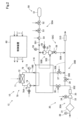
図2は、燃料電池システム10の詳細構成を説明するための図である。図2では、燃料電池スタック116に供給されたり、燃料電池スタック116から排出されたりする燃料ガスや酸化剤ガスや冷媒の向きは矢印で記載している。燃料電池システム10は、上述の燃料電池スタック116、酸化剤ガス給排系30、燃料ガス給排系50、冷媒循環系70に加え、制御装置60を有する。制御装置60は、燃料電池システム10の動作を制御する。制御装置60の詳細は後述する。
FIG. 2 is a diagram for explaining the detailed configuration of the
酸化剤ガス給排系30は、酸化剤ガス供給系30Aと、酸化剤ガス排出系30Bとを備える。酸化剤ガス供給系30Aは、燃料電池スタック116のカソードに酸化剤ガスを供給する。酸化剤ガス供給系30Aは、酸化剤ガス供給路302と、温度センサとしての外気温センサ38と、エアクリーナ31と、コンプレッサ33と、モータ34と、インタークーラ35と、第1調圧弁36と、を有する。
The oxidizing gas supply/
酸化剤ガス供給路302は、燃料電池スタック116の上流側に配置され、外部と燃料電池スタック116のカソードとを連通させる管である。外気温センサ38は、燃料電池システム10に関する温度を計測する。具体的には、外気温センサ38は、エアクリーナ31に取り込まれる酸化剤ガスである空気の温度、すなわち環境温度である外気温を計測する。外気温センサ38の計測結果は制御装置60に送信される。エアクリーナ31は、酸化剤ガス供給路302のうちでコンプレッサ33よりも上流側に設けられ、燃料電池スタック116に供給される酸化剤ガス中の異物を除去する。コンプレッサ33は、燃料電池スタック116よりも上流側の酸化剤ガス供給路302に設けられ、制御装置60からの指示に応じて圧縮した空気をカソードに向けて吐出する。コンプレッサ33は、制御装置60からの指示に応じて動作するモータ34によって駆動される。インタークーラ35は、酸化剤ガス供給路302のうちでコンプレッサ33よりも下流側に設けられている。インタークーラ35は、コンプレッサ33によって圧縮されて高温となった酸化剤ガスを冷却する。第1調圧弁36は、電磁弁や電動弁である。第1調圧弁36は、制御装置60によって開度が調整されることで、酸化剤ガス供給路302から燃料電池スタック116に向かう酸化剤ガスの流量を調整する。
The oxidizing
酸化剤ガス排出系30Bは、カソードを流通した酸化剤ガスを外部に排出する。酸化剤ガス排出系30Bは、酸化剤ガス排出路308と、バイパス路306と、第2調圧弁37と、第3調圧弁39とを有する。酸化剤ガス排出路308は、燃料電池スタック116のカソードから排出された酸化剤ガス(「酸化剤オフガス」とも呼ぶ。)や、バイパス路306を流通した酸化剤ガスを外部に排出するための管である。第2調圧弁37は、電磁弁や電動弁である。第2調圧弁37は、制御装置60によって開度が調整されることで燃料電池スタック116のカソード側流路の背圧を調整する。第2調圧弁37は、酸化剤ガス排出路308のうちでバイパス路306が接続された地点よりも上流側に配置されている。酸化剤ガス排出路308の下流側端部にはマフラー310が配置されている。
The oxidizing
第3調圧弁39は、バイパス路306に配置されている。第3調圧弁39は、電磁弁や電動弁である。第3調圧弁39は、制御装置60によって開度が調整されることでバイパス路306を流通する酸化剤ガスの流量を調整する。バイパス路306は、燃料電池スタック116を経由することなく、酸化剤ガス供給路302と酸化剤ガス排出路308とを接続する管である。
The third
燃料ガス給排系50は、燃料ガス供給系50Aと、燃料ガス循環系50Bと、燃料ガス排出系50Cとを備える。
The fuel gas supply and
燃料ガス供給系50Aは、燃料電池スタック116のアノードに燃料ガスを供給する。燃料ガス供給系50Aは、燃料ガスタンク51と、燃料ガス供給路501と、開閉弁52と、レギュレータ53と、インジェクター54と、圧力センサ59と、を備える。燃料ガスタンク51は、例えば高圧の水素ガスを貯蔵している。燃料ガス供給路501は、燃料ガスタンク51と燃料電池スタック116とに接続され、燃料ガスタンク51から燃料電池スタック116に向かう燃料ガスが流通する管である。開閉弁52は、開弁状態において燃料ガスタンク51の燃料ガスを下流側へと流通させる。レギュレータ53は、制御装置60の制御によって、インジェクター54よりも上流側における燃料ガスの圧力を調整する。インジェクター54は、燃料ガス供給路501のうち、後述する燃料ガス循環路502の合流地点よりも上流側に配置されている。インジェクター54は、制御部62によって設定された駆動周期や開弁時間に応じて、電磁的に駆動する開閉弁であり、燃料電池スタック116に供給される燃料ガス供給量を調整する。圧力センサ59は、燃料ガス供給路501のうちでインジェクター54よりも下流側の内部圧力(燃料ガスの供給圧力)を計測する。計測結果は制御装置60に送信される。
The fuel
燃料ガス循環系50Bは、燃料電池スタック116から排出される燃料ガス(「燃料オフガス」とも呼ぶ。)を再び燃料ガス供給路501に循環させる。燃料ガス循環系50Bは、燃料ガス循環路502と、気液分離器57と、循環ポンプ55と、モータ56とを有する。燃料ガス循環路502は、燃料電池スタック116と燃料ガス供給路501とに接続され、燃料ガス供給路501に向かう燃料オフガスが流通する管である。気液分離器57は、燃料ガス循環路502に設けられ、液水混じりのアノードオフガスから液水を分離する。循環ポンプ55は、モータ56を駆動させることで燃料ガス循環路502内のアノードオフガスを燃料ガス供給路501に向かって循環させる。
The fuel
燃料ガス排出系50Cは、アノードオフガスや燃料電池スタック116の発電によって生じた液水を外部へ排出する。燃料ガス排出系50Cは、排気排水路504と排気排水弁58と、を有する。排気排水路504は、液水を排出する気液分離器57の排出口と、外部とを連通する管である。
The fuel
排気排水弁58は、排気排水路504に配置され、排気排水路504を開閉する。排気排水弁58には、例えば、ダイヤフラム弁が用いられる。燃料電池システム10の通常運転時では、制御装置60は、予め定めたタイミングで排気排水弁58に対して開弁指示を行う。
The
冷媒循環系70は、冷媒循環路79と、冷媒循環ポンプ74と、モータ75と、ラジエータ72と、ラジエータファン71と、スタック温度センサ73とを備える。
The
冷媒循環路79は、冷媒供給路79Aと、冷媒排出路79Bとを有する。冷媒供給路79Aは、燃料電池スタック116に冷媒を供給するための管である。冷媒排出路79Bは、燃料電池スタック116から冷媒を排出するための管である。冷媒循環ポンプ74は、モータ75の駆動によって冷媒供給路79Aの冷媒を燃料電池スタック116へ送り出す。ラジエータ72は、ラジエータファン71によって風が送られて放熱することで、内部を流通する冷媒を冷却する。スタック温度センサ73は、燃料電池システム10に関する温度を計測する。具体的には、スタック温度センサ73は、冷媒排出路79B内の冷媒の温度を計測する。冷媒の温度の計測結果は、制御装置60に送信される。制御装置60は、スタック温度センサ73の計測温度を、燃料電池スタック116の温度として燃料電池システム10の動作を制御する。なお、冷媒循環系70は、冷媒を加熱するためのヒータを備えていてもよい。また、外気温センサ38に代えて、スタック温度センサ73を、課題を解決するための手段に記載の温度センサとしてもよい。
The
図3は、燃料電池システム10の電気的構成を示す概念図である。燃料電池システム10は、FDC95と、DC/ACインバータ98と、電圧センサ91と、電流センサ92とを備える。
FIG. 3 is a conceptual diagram showing the electrical configuration of the
電圧センサ91は、燃料電池スタック116の電圧を計測するために用いられる。電圧センサ91は、燃料電池スタック116の全ての燃料電池セル11それぞれと接続されており、全ての燃料電池セル11それぞれを対象に電圧を計測する。電圧センサ91は、その計測結果を制御装置60に送信する。電圧センサ91によって計測された全ての燃料電池セル11の計測電圧を合計することで燃料電池スタック116の総電圧が計測される。なお、燃料電池システム10は、電圧センサ91に代えて、燃料電池スタック116の両端の電圧を計測する電圧センサを有していてもよい。この場合、計測された両端の電圧値が、燃料電池スタック116の総電圧となる。電流センサ92は、燃料電池スタック116による出力電流値を計測し、制御装置60に送信する。
FDC95は、DC/DCコンバータとして構成された回路である。FDC95は、制御装置60から送信される電圧指令値に基づき、燃料電池スタック116の出力電圧を制御する。また、FDC95は、制御装置60から送信される電流指令値に基づき、燃料電池スタック116による出力電流を制御する。電流指令値とは、燃料電池スタック116による出力電流の目標値となる値であり、制御装置60によって設定される。制御装置60は、例えば、燃料電池スタック116の要求発電電力を用いて要求電流値を算出することで電流指令値を生成する。
FDC95 is a circuit configured as a DC/DC converter.
DC/ACインバータ98は、燃料電池スタック116と駆動用モータなどの負荷255とに接続されている。DC/ACインバータ98は、燃料電池スタック116から出力される直流電力を交流電力へと変換し、負荷255に供給する。
The DC/
燃料電池システム10は、さらに、二次電池96と、BDC97とを備える。二次電池96は、例えば、リチウムイオン電池で構成され、補助電源として機能する。また二次電池96は、負荷255への電力の供給と、燃料電池スタック116によって生じる電力や回生電力の充電とを行う。すなわち、二次電池96は、燃料電池スタック116によって発電された電力を充放電するために用いられる。
The
BDC97は、FDC95と共にDC/DCコンバータとして構成された回路であり、制御部としての制御装置60の指示に応じて二次電池96の充放電を制御する。BDC97は、二次電池96のSOC(State Of Charge:残容量)を計測し、制御装置60に送信する。
The
図4は、制御装置60の内部ブロック図である。制御装置60は、RAMやROMによって構成された記憶部68と、制御部62とを備える。制御部62は、例えば、電圧センサ91が計測した計測電圧値Vtを用いて燃料電池システム10の動作を制御する。
FIG. 4 is an internal block diagram of the
記憶部68には、制御部62が実行する各種プログラムが記憶されている。制御部62は、記憶部68の各種プログラムを実行することで、動作制御部64と、電圧条件判定部66として機能する。動作制御部64は、計測電圧値Vtなどに応じて燃料電池システム10の動作を制御する。電圧条件判定部66は、燃料電池システム10のスタートスイッチがONとなり、燃料電池システム10が始動する際に、低効率運転によって燃料電池スタック116を急速に昇温させる暖機運転を実行する場合に機能する。暖機運転は、例えば、外気温センサ38の計測値が氷点下である場合に実行される。暖機運転は、燃料電池スタック116の温度が、定常状態として予め定められた目標温度(例えば、65℃)に達するように、燃料電池スタック116の発熱を利用して燃料電池スタック116を昇温させる運転状態を指す。暖機運転では、燃料電池スタック116に供給される酸化剤ガスのストイキ比は、定常状態におけるストイキ比よりも小さく設定され、酸素濃度過電圧を増大させることにより、燃料電池スタック116の発電損失が増大されている。酸化剤ガスのストイキ比とは、要求発電電力を発電するために必要な酸素量の最低量に対する、実際に供給した酸素量の比を意味する。本実施形態では、暖機運転における酸化剤ガスのストイキ比は1.0程度である。電圧条件判定部66は、燃料電池スタック116からの電流の取り出しである電流掃引を開始して暖機運転を実行するための予め定めた電圧条件を満たすかどうかを判定する。この詳細は後述する。
The
図5は、二次電池96の温度特性を示す図である。リチウムイオン電池などの二次電池は、氷点下、特に-20℃(摂氏)以下になると、急激に充放電可能な電力の幅が狭くなる。これにより、燃料電池スタック116の発電電力が要求発電電力よりも超過したり、不足したりした場合に、二次電池96に超過分の電力を充電したり、不足分の電力を二次電池96から放電したりすることが困難となる場合が生じ得る。よって、外気温センサ38の計測値が氷点下、特に-20℃以下の場合には、燃料電池スタック116の発電電力を要求発電電力から大きく乖離しないように、燃料電池システム10が制御されることが好ましい。
FIG. 5 is a diagram showing the temperature characteristics of the
図6は、燃料電池システム10の始動処理を示すフローチャートである。図7は、動作点移行処理を示すフローチャートである。図8は、始動処理の開始から目標動作点Pgに至るまでの燃料電池スタック116の電圧(総電圧)と電流の関係を示す第1の図である。図9は、始動処理の開始から目標動作点Pgに至るまでの燃料電池スタック116の電圧(総電圧)と電流の関係を示す第2の図である。なお、図8に示す点線の曲線は、燃料電池スタック116のある要求発電電力(例えば、目標動作点Pgにおける要求発電電力)と同じ発電電力を示す動作点を結ぶ等パワーラインPLである。図6に示す始動処理は、燃料電池システム10のスタートスイッチがONになったことをトリガーに開始される。
FIG. 6 is a flowchart showing the startup process of the
図6に示すように、制御部62は暖機要求があるかどうかを判定する(ステップS10)。本実施形態では、制御部62は、外気温センサ38の計測値が予め定めた温度以下である場合に、暖機要求があると判定する。予め定めた温度は、例えば氷点であってもよく、氷点よりも低い温度であってもよい。制御部62は、暖機要求がないと判定した場合には(ステップS10;No)、始動処理を終了する。始動処理を終了した以降においては、制御部62は、例えば、負荷255からの要求に応じて燃料電池スタック116を発電させる通常発電処理を実行する。
As shown in FIG. 6, the
一方で、動作制御部64は、暖機要求があると判定した場合には(ステップS10:Yss)、電流掃引を開始して暖機運転を実行する前に、酸化剤ガス供給系30Aを含む酸化剤ガス給排系30を制御して、各燃料電池セル11のカソードに酸素を含む酸化剤ガスの供給を開始する(ステップS20)。これにより、燃料電池スタック116の電圧を予め定めた電圧条件を満たすまで上昇させる。また、制御部62は、ステップS20において、燃料ガス給排系50を制御して、各燃料電池セル11のアノードに予め定めた流量の燃料ガスの供給を開始する。また、制御部62は、ステップS20において、冷媒循環系70の動作を制御して冷媒の循環を開始する。
On the other hand, if the
予め定めた電圧条件は、暖機運転が実行された場合に、各燃料電池セル11のアノードからカソードに伝導した水素イオンが、カソードに存在する酸素と結合することで、カソードでの水素の再結合を抑制できる条件に設定される。つまり、予め定めた電圧条件は、カソードに伝導した水素イオンと結合できるだけの酸素が十分に存在すると判定できる電圧条件に設定される。本実施形態では、予め定めた電圧条件は、燃料電池スタック116の総電圧値によって規定されており、電圧センサ91の総電圧値を表す計測電圧値(総計測電圧値)Vtが予め定めた基準電圧値Vsを超えたという条件である。基準電圧値Vsは、例えば、Vc×Lnである。Vcは、1つの燃料電池セル11のセル基準電圧値であり、Lnは燃料電池セル11の積層枚数である。Vcは、燃料電池セル11のカソードに酸素が十分に供給されたと判定できる値、例えば、0.88V以上に設定される。なお、Vcの上限は、燃料電池セル11の触媒層が劣化することを抑制できる程度の値である。本実施形態では、Vcは0.88Vに設定されている。
The predetermined voltage condition is such that when warm-up operation is executed, hydrogen ions conducted from the anode to the cathode of each
ステップS20の次に、電圧条件判定部66は、電圧センサ91の計測電圧値Vtが、基準電圧値Vsを超えたか否かを判定する(ステップS30)。計測電圧値Vtが基準電圧値Vs以下の場合には(ステップS30:No)、動作制御部64はステップS20の処理を中止することなく継続する。一方で、計測電圧値Vtが基準電圧値Vsを越えた場合には(ステップS30:Yes)、動作制御部64は、燃料電池スタック116からの電流掃引を許可し(ステップS40)、動作点移行処理が開始される(ステップS50)。つまり、電流掃引が許可されることで、ステップS50の動作点移行処理における電流掃引を開始する。
Next to step S20, the voltage
動作点移行処理は、暖機運転の一部の処理である。図8の矢印の向きで示すように、動作点移行処理は、電流掃引を開始してから、燃料電池スタック116の目標電圧値Vgと目標電流値Igとで定まる目標動作点Pgに至るまでの期間(遷移期間)に実行される処理である。制御部62は、遷移期間の少なくとも一部において、燃料電池スタック116の電圧値と電流値とで定まる動作点を移行させる場合に、動作点が燃料電池スタック116の要求発電電力と同じ発電電力を示す等パワーラインPL上となるように、電圧指令値と電流指令値とを設定する。本実施形態では、遷移期間のうちで計測電圧値Vtが切替電圧値Vswとなった以降では、動作点を移行させる場合に、等パワーラインPL上となるように、電圧指令値と電流指令値とが設定される。なお他の実施形態では、遷移期間の全部において、動作点を移行させる場合に、等パワーラインPL上となるように、電圧指令値と電流指令値とが設定されてもよい。動作点移行処理後には、目標動作点Pgにおいて、予め定めた目標温度になるまで暖機運転が実行される。
The operating point transition process is a part of the warm-up operation. As shown by the direction of the arrow in FIG. 8, the operating point transition process starts from the start of the current sweep until reaching the target operating point Pg determined by the target voltage value Vg and target current value Ig of the
ステップS50の動作点移行処理の詳細を説明する前に、図9を用いてステップS40の電流掃引許可までの処理内容を説明する。時刻t0において暖機要求があると判定されて、各燃料電池セル11のカソードへの酸化剤ガスの供給が開始される。酸化剤ガスがカソードに供給されると、燃料電池スタック116の総電圧が上昇する。本実施形態では、時刻t1において燃料電池スタック116の総電圧が基準電圧値Vsを越える。これにより、時刻t1から動作点移行処理が実行される。図8に示すように、動作点移行処理は、電流掃引を開始してから目標動作点Pgに至るまでに実行される処理である。動作点移行処理を含む暖機運転制御では、燃料電池スタック116の要求発電電力が大きく変動することを抑制するために、コンプレッサ33(図2)の回転数は予め定めた目標回転数に到達後は一定に維持することが好ましい。よって、暖機運転制御では、コンプレッサ33が目標回転数に到達した後において、カソードへの酸化剤ガスの供給流量を変化させる場合には、第2調圧弁37の開度や第3調圧弁39の開度を調整することで調整される。なお、本実施形態における暖機運転制御では、第1調圧弁36は全開に維持される。
Before explaining the details of the operating point transition process in step S50, the content of the process up to the current sweep permission in step S40 will be explained using FIG. At time t0, it is determined that there is a warm-up request, and the supply of oxidant gas to the cathode of each
図7に示すように、動作制御部64は、遷移期間のうち計測電圧値Vtが切替電圧値Vswに至るまでの切替前期間では、実電圧制御を実行する(ステップS52)。実電圧制御では、動作制御部64は、燃料電池スタック116の要求発電電力と、燃料電池スタック116の実電圧である電圧センサ91の計測電圧値Vtとを用いて電流指令値を設定する。具体的には、動作制御部64は、要求発電電力を計測電圧値Vtで除することによって電流指令値を算出することで設定する。実電圧制御では、動作制御部64は、算出した電流指令値となるようにFDC95を制御して電流掃引を行う。
As shown in FIG. 7, the
電圧条件判定部66は、ステップS52の実電圧制御を開始した後に、計測電圧値Vtが予め定めた切替電圧値Vswに到達したか否かを判定する(ステップS54)。計測電圧値Vtが切替電圧値VswになるまではステップS52が実行される。計測電圧値Vtが切替電圧値Vswとなった場合、動作制御部64は通常電流制御と待機制御とのいずれか一方の制御を実行する(ステップS56)。すなわち、遷移期間のうち、計測電圧値Vtが切替電圧値Vswとなった時点から目標動作点Pgに到達する時点までの切替後期間では、通常電流制御と待機制御とのいずれか一方の制御が実行される。
After starting the actual voltage control in step S52, the voltage
待機制御は、切替後期間において一定の条件を満たした場合に通常電流制御を中断して実行される。切替電圧値Vswは、目標電圧値Vgに予め定めた加算電圧値Vadを加えた値に設定される。加算電圧値Vadは、過度な電流掃引が生じた場合でも目標電圧値Vgを下回らない程度の値に設定することが好ましい。本実施形態では、加算電圧値Vadは66Vに設定されている。 Standby control is executed by interrupting normal current control when certain conditions are met in the post-switching period. The switching voltage value Vsw is set to a value obtained by adding a predetermined additional voltage value Vad to the target voltage value Vg. The additional voltage value Vad is preferably set to a value that does not fall below the target voltage value Vg even if an excessive current sweep occurs. In this embodiment, the addition voltage value Vad is set to 66V.
通常電流制御では、制御部62は、目標電流値Igまで予め定めた割合で電流指令値を上昇させる。制御部62は、計測電圧値Vtが電圧指令値よりも低い値である制御開始電圧値Vcsになった場合に、通常電流制御を中断して待機制御を実行する。待機制御では、制御部62は、制御開始電圧値Vcsになった時点の電流指令値を保持することで、電流指令値を一定に維持する。これにより、制御部62は、燃料電池スタック116の電圧を上昇させ、計測電圧値Vtが電圧指令値以上の値である許可電圧値になった場合に、電流指令値の変更を許可することで待機制御を終了する。なお、制御開始電圧値Vcsは、計測電圧値Vtが電圧指令値を下回った直後に待機制御が実行されるように設定されていてもよいし、計測電圧値Vtの精度を考慮して電圧指令値よりも予め定めた値(例えば5V)だけ低く設定されていてもよい。また、許可電圧値Vpは、電圧指令値と同じ値であってもよいし、計測電圧値Vtの精度を考慮して電圧指令値よりも一定値(例えば5V)だけ高い値であってもよい。待機制御では、制御部62は、図2に示す第2調圧弁37や第3調圧弁39の開度を調整することで燃料電池スタック116へ供給する酸化剤ガスの流量を増大させてもよい。これにより、燃料電池スタック116の電圧をより効率的に上昇させることができる。制御部62は、待機制御の実行中において電流指令値の変更を許可することで、通常電流制御を再開できる。
In normal current control, the
図9に示すように、時刻t3において計測電圧値Vtが電圧指令値である目標電圧値Vgより低い値である制御開始電圧値Vcsになったとする。なお、時刻t3では、電流センサ92(図3)の計測電流値Itは目標電流値Igに到達していない。この場合、時刻t3において計測電圧値Vtが制御開始電圧値Vcsになったので、制御部62は通常電流制御を中断して待機制御を実行する。つまり、制御部62は、時刻t3における電流指令値を保持することで、電流指令値を一定値Iaに維持する。
As shown in FIG. 9, it is assumed that the measured voltage value Vt reaches the control start voltage value Vcs, which is a value lower than the target voltage value Vg, which is the voltage command value, at time t3. Note that at time t3, the measured current value It of the current sensor 92 (FIG. 3) has not reached the target current value Ig. In this case, since the measured voltage value Vt reaches the control start voltage value Vcs at time t3, the
時刻t4において計測電圧値Vtが電圧指令値である目標電圧値Vg以上の値である許可電圧値Vpに到達したため、制御部62は、待機制御を終了して通常電流制御を再開する。これにより、通常電流制御によって予め定めた割合で電流指令値が目標動作点Pgに向かって再び上昇する。また、時刻t5~時刻t6の期間や時刻t7~時刻t8の期間でも同様に、待機制御が実行される。
At time t4, the measured voltage value Vt reaches the permission voltage value Vp, which is a value greater than or equal to the target voltage value Vg, which is the voltage command value, so the
図7に示すように、制御部62は、燃料電池スタック116の動作点(計測電流値It、計測電圧値Vt)が、目標動作点Pgに到達したか否かを判定する(ステップS58)。動作点が目標動作点Pgに到達するまで、制御部62は通常電流制御と待機制御とのいずれか一方の制御を実行する。一方で、動作点が目標動作点Pgに到達した場合には、制御部62は、動作点移行処理を終了する。図9に示す例では、時刻t9において、動作点が目標動作点Pgに到達する。動作点移行処理が終了した後には、制御部62は、燃料電池スタック116が目標温度に到達するまで、目標動作点Pgにおいて暖機運転を実行する。制御部62は、スタック温度センサ73(図2)の計測値を、燃料電池スタック116の温度として目標温度に到達したか否かを判定する。
As shown in FIG. 7, the
上記第1実施形態によれば、計測電圧値Vtが予め定めた電圧条件を満たした後に電流掃引を行うことで、燃料電池スタック116のカソードに酸素を十分に存在させた後に暖機運転を行うことができる。これにより、暖機運転中にカソードにおける酸素が欠乏してポンピング水素が発生する可能性を低減できる。ポンピング水素が発生する可能性を低減することで、酸化剤ガス排出路308を介して外部に水素が放出されることを抑制できる。加えて、この形態によれば、制御部62は、遷移期間において、計測電圧値Vtが電圧指令値より低い値である制御開始電圧値Vcsになった場合に、待機制御を実行する。計測電圧値Vtが電圧指令値よりも低い値になった場合、カソードに酸素が十分に存在していない。よって、この場合において、制御部62は、電流指令値を一定に維持して計測電圧値Vtが電圧指令値以上の値である許可電圧値Vpとなるとなるまで電流指令値を一定に維持することで、カソードの酸素が不足することを抑制できる。これにより、ポンピング水素の発生をより抑制できる。
According to the first embodiment, by performing a current sweep after the measured voltage value Vt satisfies a predetermined voltage condition, the warm-up operation is performed after oxygen is sufficiently present in the cathode of the
また上記第1実施形態によれば、切替前期間においては、実電圧制御が実行されるので、ポンピング水素の発生を抑制しつつ、要求発電電力と、実際の発電電力とのずれが大きくなることを抑制できる。これにより、二次電池96の充放電量が許容量を超える可能性を低減できる。また、切替後期間においては、通常電流制御が実行されるので、過度な電流掃引が実行されることを抑制できる。またこの形態によれば、通常電流制御を実行している場合において、計測電圧値Vtが制御開始電圧値Vcsになった場合に、待機制御が実行されることで、カソードの酸素が不足することを抑制できるので、ポンピング水素の発生を抑制できる。
Further, according to the first embodiment, since the actual voltage control is executed in the pre-switching period, the generation of pumped hydrogen is suppressed while the difference between the requested generated power and the actual generated power becomes large. can be suppressed. This can reduce the possibility that the amount of charging and discharging of the
また上記第1実施形態によれば、制御部62は、遷移期間において動作点を移行させる場合に、等パワーラインPL上となるように、電圧指令値と電流指令値とを設定するので、要求発電電力に対して燃料電池スタック116の実際の発電電力が乖離することを抑制できる。これにより、二次電池96の充放電量を一定の範囲内に制御できるので、二次電池96の充放電量が許容量を超える可能性を低減できる。
Further, according to the first embodiment, the
B.第2実施形態:
図10は、第2実施形態に燃料電池システム10の始動処理を示すフローチャートである。上記第1実施形態の始動処理(図6)との違いは、ステップS30aである。その他のステップについては第1実施形態と第2実施形態とで同様のステップであるため、同一符号を付すと共に説明を省略する。第2実施形態では、電流掃引が許可される予め定めた電圧条件は、端部側燃料電池セル11eの計測電圧値が予め定めた端部側基準電圧値を越えたという条件である。
B. Second embodiment:
FIG. 10 is a flowchart showing the startup process of the
ステップS20の次に、電圧条件判定部66は、電圧センサ91によって計測された端部側燃料電池セル11eの計測電圧値が、予め定めた端部側基準電圧値Vceを超えたか否かを判定する(ステップS30a)。端部側基準電圧値Vceは、端部側燃料電池セル11eのカソードに酸素が十分に供給されたと判定できる値、例えば、0.8Vに設定されている。ここで、複数の端部側燃料電池セル11eの各計測電圧値を用いてステップS30aの判定が行われる場合、制御部62は、例えば、複数の端部側燃料電池セル11eのうちの予め定めたセル数の各計測電圧値が、それぞれ端部側基準電圧値Vceを越えたか否かを判定する。
Next to step S20, the voltage
上記第2実施形態によれば、上記第1実施形態と同様の構成を有する点において同様の効果を奏する。例えば、端部側燃料電池セル11eの計測電圧値が予め定めた電圧条件を満たした後に電流掃引を行うことで、燃料電池スタック116のカソードに酸素を十分に存在させた後に暖機運転を行うことができる。これにより、暖機運転中にカソードにおける酸素が欠乏してポンピング水素が発生する可能性を低減できる。ポンピング水素が発生する可能性を低減することで、酸化剤ガス排出路308を介して外部に水素が放出されることを抑制できる。また、燃料電池スタック116の積層方向SDの長さが長くなって、酸化剤ガスが他方の端部側に到達するのに相当の時間がかかるような場合でも、他方の端部側の端部側燃料電池セル11eに位置する電圧値が予め定めた電圧条件を満たすかどうかを判定することで、ポンピング水素の発生をより抑制できる。つまり、燃料電池スタック116の他方の端部側が、一方の端部側よりも酸化剤ガスの到達が遅れることで、酸化剤ガス供給による電圧上昇が一方の端部側よりも他方の端部側の方が遅くなった場合でも。電圧上昇が遅い端部側燃料電池セル11eの計測電圧値が予め定めた電圧条件を満たすかどうかを判定することで、ポンピング水素の発生をより抑制できる。
According to the second embodiment, the same effects as those of the first embodiment can be obtained in that the second embodiment has the same configuration. For example, by performing a current sweep after the measured voltage value of the end-
C.他の実施形態:
C-1.第1の他の実施形態:
上記第1実施形態において、燃料電池システム10は、燃料電池スタック116の一方の端部側からのみ、燃料ガス、酸化剤ガス、冷媒を供給したり排出したりしていたが、これに限定されるものではない。例えば、燃料電池システム10は、燃料電池スタック116の一方の端部側から燃料ガス、酸化剤ガス、冷媒を供給し、他方の端部側から燃料ガス、酸化剤ガス、冷媒を排出してもよい。
C. Other embodiments:
C-1. First other embodiment:
In the first embodiment, the
C-2.第2の他の実施形態:
制御部62は、上記第1実施形態では燃料電池スタック116の総電圧値が電圧条件を満たした場合に電流掃引を開始し、上記第2実施形態では端部側燃料電池セル11eの電圧値が電圧条件を満たす場合に電流掃引を開始していたが限定されるものではない。例えばは、燃料電池スタック116の一方側に位置する燃料電池セル11や、中央に位置する燃料電池セル11の電圧値が電圧条件を満たした場合に、電流掃引を開始してもよい。
C-2. Second alternative embodiment:
In the first embodiment, the
C-3.第3の他の実施形態:
上記各実施形態では、制御部62は、遷移期間において、実電圧制御や通常電流制御を実行していたが、これに限定されるものではない。例えば、制御部62は、遷移期間において、待機制御に加え、実電圧制御と通常電流制御のいずれか一方の制御のみを実行してもよいし他の制御を実行してもよい。また、例えば、遷移期間において、電流指令値を一時的に下げる制御が行われてもよい。
C-3. Third other embodiment:
In each of the above embodiments, the
C-4.第4の他の実施形態:
上記各実施形態では、図6のステップS10では、制御部62は、外気温センサ38の計測値が予め定めた温度以下である場合に、暖気要求があると判定していたが、これに限定されるものではない。例えば、制御部62は、スタック温度センサ73の計測値が予め定めた温度以下である場合に、暖気要求があると判定してもよい。
C-4. Fourth other embodiment:
In each of the embodiments described above, in step S10 of FIG. 6, the
本開示は、上述の実施形態に限られるものではなく、その趣旨を逸脱しない範囲において種々の構成で実現することができる。例えば、発明の概要の欄に記載した各形態中の技術的特徴に対応する実施形態の技術的特徴は、上述の課題の一部又は全部を解決するために、あるいは、上述の効果の一部又は全部を達成するために、適宜、差し替えや、組み合わせを行うことが可能である。また、その技術的特徴が本明細書中に必須なものとして説明されていなければ、適宜、削除することが可能である。 The present disclosure is not limited to the embodiments described above, and can be implemented in various configurations without departing from the spirit thereof. For example, the technical features of the embodiments corresponding to the technical features in each form described in the column of the summary of the invention may be Alternatively, in order to achieve all of the above, it is possible to perform appropriate replacements or combinations. Further, unless the technical feature is described as essential in this specification, it can be deleted as appropriate.
10…燃料電池システム、11…燃料電池セル、11e…端部側燃料電池セル、12…燃料電池車両、30…酸化剤ガス給排系、30A…酸化剤ガス供給系、30B…酸化剤ガス排出系、31…エアクリーナ、33…コンプレッサ、34…モータ、35…インタークーラ、36…第1調圧弁、37…第2調圧弁、38…外気温センサ、39…第3調圧弁、50…燃料ガス給排系、50A…燃料ガス供給系、50B…燃料ガス循環系、50C…燃料ガス排出系、51…燃料ガスタンク、52…開閉弁、53…レギュレータ、54…インジェクター、55…循環ポンプ、56…モータ、57…気液分離器、58…排気排水弁、59…圧力センサ、60…制御装置、62…制御部、64…動作制御部、66…電圧条件判定部、68…記憶部、70…冷媒循環系、71…ラジエータファン、72…ラジエータ、73…スタック温度センサ、74…冷媒循環ポンプ、75…モータ、79…冷媒循環路、79A…冷媒供給路、79B…冷媒排出路、91…電圧センサ、92…電流センサ、96…二次電池、98…DC/ACインバータ、110…第1エンドターミナル、115…開口部、116…燃料電池スタック、120…第2エンドターミナル、255…負荷、302…酸化剤ガス供給路、306…バイパス路、308…酸化剤ガス排出路、310…マフラー、501…燃料ガス供給路、502…燃料ガス循環路、504…排気排水路、Ia…一定値、Ig…目標電流値、It…計測電流値、Mfa…マニホールド、Mfb…マニホールド、PL…等パワーライン、Pg…目標動作点、SD…積層方向、Vce…端部側基準電圧値、Vcs…制御開始電圧値、Vg…目標電圧値、Vp…許可電圧値、Vad…加算電圧値、Vs…基準電圧値、Vsw…切替電圧値、Vt…計測電圧値
DESCRIPTION OF
Claims (2)
積層された複数の燃料電池セルであって、アノードとカソードとをそれぞれ有する複数の燃料電池セルを有する燃料電池スタックと、
前記燃料電池スタックの電圧を計測するための電圧センサと、
前記カソードに酸素を含む酸化剤ガスを供給するための酸化剤ガス供給系と、
前記アノードに燃料ガスを供給するための燃料ガス供給系と、
前記燃料電池システムに関する温度を計測する温度センサと、
前記電圧センサが計測した計測電圧値を用いて前記燃料電池システムの動作を制御する制御部と、を備え、
前記制御部は、前記燃料電池システムを始動する際に、前記温度センサの計測値が予め定めた温度以下である場合には、
前記燃料電池スタックの電流掃引を開始する前に、前記酸化剤ガス供給系を動作させて前記カソードに前記酸化剤ガスを供給することで、前記燃料電池スタックの電圧を予め定めた電圧条件を満たすまで上昇させ、
前記計測電圧値が前記電圧条件を満たした場合に、前記燃料電池スタックからの電流掃引を開始して、前記燃料電池スタックを昇温させる暖機運転を実行し、
前記制御部は、前記暖機運転を実行する際には、前記電流掃引を開始してから前記暖機運転における目標電圧値と目標電流値とで定まる目標動作点に至るまでの遷移期間において、前記計測電圧値が電圧指令値より低い値である制御開始電圧値になった場合に、電流指令値を一定に維持する待機制御を実行し、前記待機制御の実行中において、前記計測電圧値が前記電圧指令値以上の値である許可電圧値になった場合に、前記電流指令値の変更を許可することで前記待機制御を終了し、
前記制御部は、
前記遷移期間のうち、前記計測電圧値が予め定めた切替電圧値となった時点から前記目標動作点に到達する時点までの切替後期間では、前記目標電流値まで予め定めた割合で前記電流指令値を上昇させる通常電流制御を実行し、
前記遷移期間のうち、前記計測電圧値が前記切替電圧値に至るまでの切替前期間では、前記燃料電池スタックの要求発電電力と前記計測電圧値とを用いて前記電流指令値を設定し、設定した前記電流指令値となるように前記電流掃引を行う実電圧制御を実行し、
前記通常電流制御を実行している場合において、前記計測電圧値が前記制御開始電圧値になった場合に、前記通常電流制御を中断して前記待機制御を実行し、前記計測電圧値が前記許可電圧値になった場合に、前記電流指令値の変更を許可することで前記待機制御を終了して前記通常電流制御を再開する、燃料電池システム。 A fuel cell system,
a fuel cell stack including a plurality of stacked fuel cells each having an anode and a cathode;
a voltage sensor for measuring the voltage of the fuel cell stack;
an oxidizing gas supply system for supplying an oxidizing gas containing oxygen to the cathode;
a fuel gas supply system for supplying fuel gas to the anode;
a temperature sensor that measures temperature related to the fuel cell system;
A control unit that controls the operation of the fuel cell system using the measured voltage value measured by the voltage sensor,
When starting the fuel cell system, if the measured value of the temperature sensor is below a predetermined temperature, the control unit:
Before starting the current sweep of the fuel cell stack, the oxidizing gas supply system is operated to supply the oxidizing gas to the cathode, so that the voltage of the fuel cell stack satisfies a predetermined voltage condition. raise it to
When the measured voltage value satisfies the voltage condition, starting a current sweep from the fuel cell stack and performing a warm-up operation to raise the temperature of the fuel cell stack;
When executing the warm-up operation, the control section includes: in a transition period from starting the current sweep until reaching a target operating point determined by a target voltage value and a target current value in the warm-up operation; When the measured voltage value reaches a control start voltage value that is lower than the voltage command value, standby control is executed to maintain the current command value constant, and during the execution of the standby control, the measured voltage value is terminating the standby control by permitting a change in the current command value when the permissible voltage value is equal to or higher than the voltage command value;
The control unit includes:
During the transition period, during the post-switching period from the time when the measured voltage value reaches the predetermined switching voltage value to the time when the target operating point is reached, the current command is increased at a predetermined rate up to the target current value. Perform normal current control to increase the value,
In the transition period, in a pre-switching period in which the measured voltage value reaches the switching voltage value, the current command value is set using the required generated power of the fuel cell stack and the measured voltage value. Execute actual voltage control to perform the current sweep so that the current command value becomes the current command value,
When the normal current control is being executed, if the measured voltage value reaches the control start voltage value, the normal current control is interrupted and the standby control is executed, and the measured voltage value is set to the permission level. When the voltage value is reached, the fuel cell system terminates the standby control and restarts the normal current control by allowing a change in the current command value.
積層された複数の燃料電池セルであって、アノードとカソードとをそれぞれ有する複数の燃料電池セルを有する燃料電池スタックと、
前記燃料電池スタックの電圧を計測するための電圧センサと、
前記カソードに酸素を含む酸化剤ガスを供給するための酸化剤ガス供給系と、
前記アノードに燃料ガスを供給するための燃料ガス供給系と、
前記燃料電池システムに関する温度を計測する温度センサと、
前記電圧センサが計測した計測電圧値を用いて前記燃料電池システムの動作を制御する制御部と、を備え、
前記制御部は、前記燃料電池システムを始動する際に、前記温度センサの計測値が予め定めた温度以下である場合には、
前記燃料電池スタックの電流掃引を開始する前に、前記酸化剤ガス供給系を動作させて前記カソードに前記酸化剤ガスを供給することで、前記燃料電池スタックの電圧を予め定めた電圧条件を満たすまで上昇させ、
前記計測電圧値が前記電圧条件を満たした場合に、前記燃料電池スタックからの電流掃引を開始して、前記燃料電池スタックを昇温させる暖機運転を実行し、
前記制御部は、前記暖機運転を実行する際には、前記電流掃引を開始してから前記暖機運転における目標電圧値と目標電流値とで定まる目標動作点に至るまでの遷移期間において、前記計測電圧値が電圧指令値より低い値である制御開始電圧値になった場合に、電流指令値を一定に維持する待機制御を実行し、前記待機制御の実行中において、前記計測電圧値が前記電圧指令値以上の値である許可電圧値になった場合に、前記電流指令値の変更を許可することで前記待機制御を終了し、
前記燃料電池システムは、さらに、前記燃料電池スタックによって発電された電力を充放電する二次電池を有し、
前記制御部は、前記遷移期間の少なくとも一部において、前記燃料電池スタックの電圧値と電流値とで定まる動作点を移行させる場合に、前記動作点が前記燃料電池スタックの要求発電電力と同じ発電電力を示す前記燃料電池スタックの等パワーライン上となるように、前記電圧指令値と前記電流指令値とを設定する、燃料電池システム。 A fuel cell system,
a fuel cell stack including a plurality of stacked fuel cells each having an anode and a cathode;
a voltage sensor for measuring the voltage of the fuel cell stack;
an oxidizing gas supply system for supplying an oxidizing gas containing oxygen to the cathode;
a fuel gas supply system for supplying fuel gas to the anode;
a temperature sensor that measures temperature related to the fuel cell system;
A control unit that controls the operation of the fuel cell system using the measured voltage value measured by the voltage sensor,
When starting the fuel cell system, if the measured value of the temperature sensor is below a predetermined temperature, the control unit:
Before starting the current sweep of the fuel cell stack, the oxidizing gas supply system is operated to supply the oxidizing gas to the cathode, so that the voltage of the fuel cell stack satisfies a predetermined voltage condition. raise it to
When the measured voltage value satisfies the voltage condition, starting a current sweep from the fuel cell stack and performing a warm-up operation to raise the temperature of the fuel cell stack;
When executing the warm-up operation, the control section includes: in a transition period from starting the current sweep until reaching a target operating point determined by a target voltage value and a target current value in the warm-up operation; When the measured voltage value reaches a control start voltage value that is lower than the voltage command value, standby control is executed to maintain the current command value constant, and during the execution of the standby control, the measured voltage value is terminating the standby control by permitting a change in the current command value when the permissible voltage value is equal to or higher than the voltage command value;
The fuel cell system further includes a secondary battery that charges and discharges the power generated by the fuel cell stack,
When shifting the operating point determined by the voltage value and current value of the fuel cell stack during at least a portion of the transition period, the control unit may cause the operating point to be the same as the required generated power of the fuel cell stack. A fuel cell system in which the voltage command value and the current command value are set so as to be on an equal power line of the fuel cell stack indicating electric power.
Priority Applications (6)
| Application Number | Priority Date | Filing Date | Title |
|---|---|---|---|
| JP2020074654A JP7347315B2 (en) | 2020-04-20 | 2020-04-20 | fuel cell system |
| RU2021108867A RU2757291C1 (en) | 2020-04-20 | 2021-04-01 | Fuel cell system |
| US17/221,006 US11476478B2 (en) | 2020-04-20 | 2021-04-02 | Fuel cell system |
| EP21167161.5A EP3902041B1 (en) | 2020-04-20 | 2021-04-07 | Fuel cell system |
| CN202110399597.1A CN113540531B (en) | 2020-04-20 | 2021-04-14 | Fuel cell system |
| KR1020210048995A KR102579695B1 (en) | 2020-04-20 | 2021-04-15 | Fuel cell system |
Applications Claiming Priority (1)
| Application Number | Priority Date | Filing Date | Title |
|---|---|---|---|
| JP2020074654A JP7347315B2 (en) | 2020-04-20 | 2020-04-20 | fuel cell system |
Publications (2)
| Publication Number | Publication Date |
|---|---|
| JP2021174585A JP2021174585A (en) | 2021-11-01 |
| JP7347315B2 true JP7347315B2 (en) | 2023-09-20 |
Family
ID=75426453
Family Applications (1)
| Application Number | Title | Priority Date | Filing Date |
|---|---|---|---|
| JP2020074654A Active JP7347315B2 (en) | 2020-04-20 | 2020-04-20 | fuel cell system |
Country Status (6)
| Country | Link |
|---|---|
| US (1) | US11476478B2 (en) |
| EP (1) | EP3902041B1 (en) |
| JP (1) | JP7347315B2 (en) |
| KR (1) | KR102579695B1 (en) |
| CN (1) | CN113540531B (en) |
| RU (1) | RU2757291C1 (en) |
Families Citing this family (1)
| Publication number | Priority date | Publication date | Assignee | Title |
|---|---|---|---|---|
| US11641022B2 (en) * | 2021-01-04 | 2023-05-02 | GM Global Technology Operations LLC | Controlling purge operation for fuel cell assembly |
Citations (5)
| Publication number | Priority date | Publication date | Assignee | Title |
|---|---|---|---|---|
| JP2008269813A (en) | 2007-04-16 | 2008-11-06 | Toyota Motor Corp | Fuel cell system |
| WO2011021301A1 (en) | 2009-08-21 | 2011-02-24 | トヨタ自動車株式会社 | Fuel cell system |
| JP2012212683A (en) | 2012-07-03 | 2012-11-01 | Honda Motor Co Ltd | Method and system for starting fuel cell system under freezing point |
| JP2021174584A (en) | 2020-04-20 | 2021-11-01 | トヨタ自動車株式会社 | Fuel cell system |
| JP7153474B2 (en) | 2017-06-16 | 2022-10-14 | Line株式会社 | METHOD AND SYSTEM USING COMMUNICATION TECHNOLOGY BETWEEN DEVICES WHEN TRANSMITTING FILES USING MESSENGER |
Family Cites Families (14)
| Publication number | Priority date | Publication date | Assignee | Title |
|---|---|---|---|---|
| US6479177B1 (en) * | 1996-06-07 | 2002-11-12 | Ballard Power Systems Inc. | Method for improving the cold starting capability of an electrochemical fuel cell |
| US6887598B2 (en) | 2002-08-16 | 2005-05-03 | Generals Motors Corporation | Control system and method for starting a frozen fuel cell |
| JP2005032587A (en) * | 2003-07-07 | 2005-02-03 | Denso Corp | Fuel cell system |
| RU2506603C2 (en) * | 2003-07-09 | 2014-02-10 | Премиум Пауэр Корпорейшн | Device to control and charge selected group of battery elements |
| JP5000073B2 (en) * | 2003-09-08 | 2012-08-15 | 本田技研工業株式会社 | Fuel cell stack below freezing start method, fuel cell stack below freezing start system, and fuel cell stack designing method |
| JP4752342B2 (en) * | 2005-06-15 | 2011-08-17 | 株式会社デンソー | Fuel cell system |
| JP5200414B2 (en) | 2007-04-26 | 2013-06-05 | トヨタ自動車株式会社 | Fuel cell system |
| JP4656539B2 (en) * | 2007-11-21 | 2011-03-23 | トヨタ自動車株式会社 | Fuel cell system |
| JP4524804B2 (en) * | 2007-12-25 | 2010-08-18 | トヨタ自動車株式会社 | Fuel cell system |
| JP5329111B2 (en) * | 2008-03-25 | 2013-10-30 | 本田技研工業株式会社 | Fuel cell system and method for determining deterioration of power storage device in the system |
| RU2460179C1 (en) * | 2011-04-28 | 2012-08-27 | Федеральное государственное унитарное предприятие "Центральный научно-исследовательский институт судовой электротехники и технологии" (ФГУП "ЦНИИ СЭТ") | Power plant operating on fuel elements |
| JP6059049B2 (en) * | 2013-03-13 | 2017-01-11 | 本田技研工業株式会社 | Fuel cell system |
| JP6187774B2 (en) * | 2014-11-14 | 2017-08-30 | トヨタ自動車株式会社 | FUEL CELL SYSTEM AND FUEL CELL SYSTEM OPERATION CONTROL METHOD |
| US10714771B2 (en) | 2016-09-08 | 2020-07-14 | Daimler Ag | Below freezing start-up method for fuel cell system |
-
2020
- 2020-04-20 JP JP2020074654A patent/JP7347315B2/en active Active
-
2021
- 2021-04-01 RU RU2021108867A patent/RU2757291C1/en active
- 2021-04-02 US US17/221,006 patent/US11476478B2/en active Active
- 2021-04-07 EP EP21167161.5A patent/EP3902041B1/en active Active
- 2021-04-14 CN CN202110399597.1A patent/CN113540531B/en active Active
- 2021-04-15 KR KR1020210048995A patent/KR102579695B1/en active IP Right Grant
Patent Citations (5)
| Publication number | Priority date | Publication date | Assignee | Title |
|---|---|---|---|---|
| JP2008269813A (en) | 2007-04-16 | 2008-11-06 | Toyota Motor Corp | Fuel cell system |
| WO2011021301A1 (en) | 2009-08-21 | 2011-02-24 | トヨタ自動車株式会社 | Fuel cell system |
| JP2012212683A (en) | 2012-07-03 | 2012-11-01 | Honda Motor Co Ltd | Method and system for starting fuel cell system under freezing point |
| JP7153474B2 (en) | 2017-06-16 | 2022-10-14 | Line株式会社 | METHOD AND SYSTEM USING COMMUNICATION TECHNOLOGY BETWEEN DEVICES WHEN TRANSMITTING FILES USING MESSENGER |
| JP2021174584A (en) | 2020-04-20 | 2021-11-01 | トヨタ自動車株式会社 | Fuel cell system |
Also Published As
| Publication number | Publication date |
|---|---|
| CN113540531A (en) | 2021-10-22 |
| JP2021174585A (en) | 2021-11-01 |
| RU2757291C1 (en) | 2021-10-12 |
| KR102579695B1 (en) | 2023-09-19 |
| EP3902041A1 (en) | 2021-10-27 |
| US20210328243A1 (en) | 2021-10-21 |
| EP3902041B1 (en) | 2023-03-22 |
| US11476478B2 (en) | 2022-10-18 |
| KR20210129603A (en) | 2021-10-28 |
| CN113540531B (en) | 2024-03-01 |
Similar Documents
| Publication | Publication Date | Title |
|---|---|---|
| JP7119705B2 (en) | fuel cell system | |
| WO2008047944A1 (en) | Fuel cell system | |
| JP7347315B2 (en) | fuel cell system | |
| JP5880618B2 (en) | Fuel cell system and control method thereof | |
| TWI748913B (en) | Fuel cell system | |
| JP7342731B2 (en) | fuel cell system | |
| JP2005310435A (en) | Fuel cell system | |
| JP7298503B2 (en) | Fuel cell system and its control method | |
| CN113745604B (en) | Fuel cell system, control method thereof, and non-transitory storage medium | |
| JP6200009B2 (en) | Operation method of fuel cell system | |
| CN113540530B (en) | Fuel cell system | |
| US11962048B2 (en) | Fuel cell system with improved low temperature operation | |
| JP2020024785A (en) | Fuel battery system | |
| CN113285104B (en) | Fuel cell system and control method thereof | |
| JP2020136008A (en) | Fuel cell system | |
| JP2023155547A (en) | fuel cell system | |
| JP2021106102A (en) | Fuel cell system | |
| JP2020170650A (en) | Fuel cell system | |
| JP2006049134A (en) | Fuel cell system |
Legal Events
| Date | Code | Title | Description |
|---|---|---|---|
| A621 | Written request for application examination |
Free format text: JAPANESE INTERMEDIATE CODE: A621 Effective date: 20220523 |
|
| A977 | Report on retrieval |
Free format text: JAPANESE INTERMEDIATE CODE: A971007 Effective date: 20230227 |
|
| A131 | Notification of reasons for refusal |
Free format text: JAPANESE INTERMEDIATE CODE: A131 Effective date: 20230411 |
|
| A521 | Request for written amendment filed |
Free format text: JAPANESE INTERMEDIATE CODE: A523 Effective date: 20230605 |
|
| TRDD | Decision of grant or rejection written | ||
| A01 | Written decision to grant a patent or to grant a registration (utility model) |
Free format text: JAPANESE INTERMEDIATE CODE: A01 Effective date: 20230808 |
|
| A61 | First payment of annual fees (during grant procedure) |
Free format text: JAPANESE INTERMEDIATE CODE: A61 Effective date: 20230821 |
|
| R151 | Written notification of patent or utility model registration |
Ref document number: 7347315 Country of ref document: JP Free format text: JAPANESE INTERMEDIATE CODE: R151 |