JP7345187B2 - gaming machine - Google Patents
gaming machine Download PDFInfo
- Publication number
- JP7345187B2 JP7345187B2 JP2020067116A JP2020067116A JP7345187B2 JP 7345187 B2 JP7345187 B2 JP 7345187B2 JP 2020067116 A JP2020067116 A JP 2020067116A JP 2020067116 A JP2020067116 A JP 2020067116A JP 7345187 B2 JP7345187 B2 JP 7345187B2
- Authority
- JP
- Japan
- Prior art keywords
- special symbol
- main cpu
- game
- jackpot
- control
- Prior art date
- Legal status (The legal status is an assumption and is not a legal conclusion. Google has not performed a legal analysis and makes no representation as to the accuracy of the status listed.)
- Active
Links
Images


Classifications
-
- Y—GENERAL TAGGING OF NEW TECHNOLOGICAL DEVELOPMENTS; GENERAL TAGGING OF CROSS-SECTIONAL TECHNOLOGIES SPANNING OVER SEVERAL SECTIONS OF THE IPC; TECHNICAL SUBJECTS COVERED BY FORMER USPC CROSS-REFERENCE ART COLLECTIONS [XRACs] AND DIGESTS
- Y02—TECHNOLOGIES OR APPLICATIONS FOR MITIGATION OR ADAPTATION AGAINST CLIMATE CHANGE
- Y02E—REDUCTION OF GREENHOUSE GAS [GHG] EMISSIONS, RELATED TO ENERGY GENERATION, TRANSMISSION OR DISTRIBUTION
- Y02E60/00—Enabling technologies; Technologies with a potential or indirect contribution to GHG emissions mitigation
- Y02E60/10—Energy storage using batteries
Landscapes
- Pinball Game Machines (AREA)
Description
本発明は、パチンコ遊技機などの遊技機に関する。 The present invention relates to a gaming machine such as a pachinko gaming machine.
従来、パチンコ遊技機などの遊技機においては、発射された遊技球が転動可能な遊技領域に設けられた通過領域を遊技球が通過したことなど、所定の可変表示開始条件の成立により、画像表示装置の表示領域上に識別情報としての図柄を変動表示する制御が実行されて、変動表示された図柄を導出表示する制御が実行され、導出表示された図柄が所定の組合せ(特定の表示態様)となった場合に、遊技者に有利な大当り遊技状態に移行するようにしたものが提供されている(特許文献1参照)。 Conventionally, in gaming machines such as pachinko gaming machines, an image is displayed when a predetermined variable display start condition is met, such as when a game ball has passed through a passage area provided in a rolling game area. Control is executed to variably display symbols as identification information on the display area of the display device, control is executed to derive and display the variably displayed symbols, and the derived and displayed symbols are combined in a predetermined combination (specific display mode). ), there has been provided a game system that shifts to a jackpot game state that is advantageous to the player (see Patent Document 1).
しかしながら、従来、遊技機は、市場において新機種が断続的に求められており、新機種に取り付けられる遊技装置も改良が求められている。 However, in the past, new models of gaming machines have been intermittently sought after in the market, and improvements have also been required for the gaming devices attached to the new models .
本発明は、上記問題点に鑑みてなされたものであり、改良された遊技装置を有する遊技機を提供することを目的とする。 The present invention has been made in view of the above problems, and an object of the present invention is to provide a gaming machine having an improved gaming device .
上記の目的を達成するために、本発明は、以下のような遊技機を提供する。
本発明は、
遊技媒体が通過可能な通過領域と、
前記通過領域が設けられた透光性素材の遊技パネルと、
前記通過領域に設けられた所定方向に突出する突出部材と、
遊技媒体を検出する検出手段と、
透光性素材で形成され、遊技媒体を受け入れ可能な部分を複数有する複数受入部材と、を備え、
前記複数受入部材は、複数の遊技媒体を受け入れ可能な部分で、受け入れた遊技媒体を視認可能であり、さらに合流して流通する合流路を有し、
前記検出手段は、前記複数受入部材の受け入れ可能な部分の各々において受け入れた遊技媒体と前記合流路を通過した遊技媒体を検出し、
前記合流路は、減速手段を有し、
前記複数受入部材において複数の遊技媒体を受け入れ可能な部分で、それぞれ受け入れた遊技媒体に対して、同一の賞を付与することが可能であることを特徴とする遊技機。
In order to achieve the above object, the present invention provides the following gaming machine.
The present invention
a passage area through which game media can pass;
a game panel made of a translucent material and provided with the passage area;
a protrusion member provided in the passage area and protruding in a predetermined direction;
detection means for detecting gaming media;
a plurality of receiving members made of a translucent material and having a plurality of portions capable of receiving game media;
The plurality of receiving members are parts that can receive a plurality of game media, the received game media can be visually recognized, and further have a merging path that merges and circulates,
The detection means detects game media received in each of the acceptable portions of the plurality of receiving members and game media that have passed through the merging path,
The merging path has a deceleration means,
A gaming machine characterized in that a portion of the plurality of receiving members capable of receiving a plurality of game media is capable of awarding the same prize to each of the game media accepted.
本発明に係る遊技機は、
所定の始動条件が成立したことに応じて遊技に関する抽選を行い、抽選結果に応じて識別情報を変動し、前記識別情報の表示結果が予め定められた特別表示態様となったことに応じて遊技者に有利な特別遊技状態に制御可能な主制御手段を備え、
前記主制御手段において、高スタート用の識別情報の変動パターンテーブルを参照して識別情報の表示結果を決定した場合、低スタート用の識別情報の変動パターンテーブルを参照して識別情報の表示結果を決定した場合と比べて、単位時間あたりの前記識別情報の可変表示回数の期待値が大きいことを特徴とする。
The gaming machine according to the present invention includes:
A lottery related to the game is held in response to the establishment of a predetermined starting condition, identification information is changed according to the lottery result, and the game is started in response to the display result of the identification information becoming a predetermined special display mode. Equipped with a main control means that can control a special gaming state advantageous to the player,
When the main control means determines the display result of the identification information by referring to the variation pattern table of the identification information for a high start, the main control means determines the display result of the identification information by referring to the variation pattern table of the identification information for a low start. The feature is that the expected value of the number of variable display times of the identification information per unit time is larger than that in the determined case.
本発明によれば、改良された遊技装置を有する遊技機を提供できる。 According to the present invention, a gaming machine having an improved gaming device can be provided.
本発明の実施形態にかかる遊技機の一例として、第1のパチンコ遊技機、第2のパチンコ遊技機および第3のパチンコ遊技機を例に挙げて説明する。 As an example of a gaming machine according to an embodiment of the present invention, a first pachinko gaming machine, a second pachinko gaming machine, and a third pachinko gaming machine will be described as examples.
なお、この明細書において、特に断りがない限り、パチンコ遊技機の正面側を前方向、パチンコ遊技機の背面側を後方向、パチンコ遊技機を前方から見たときの左側を左方向、パチンコ遊技機を前方から見たときの右側を右方向、パチンコ遊技機の上側を上方向、パチンコ遊技機の下側を下方向、パチンコ遊技機を前方から見たときの時計回りの方向を右回り方向、その逆に反時計回りの方向を左回り方向として定義する。 In this specification, unless otherwise specified, the front side of the pachinko game machine is the front direction, the back side of the pachinko game machine is the rear direction, and the left side when the pachinko game machine is viewed from the front is the left direction. The right side when looking at the machine from the front is the right direction, the top of the pachinko machine is up, the bottom of the pachinko machine is down, and the clockwise direction when looking at the pachinko machine from the front is the clockwise direction. , conversely, the counterclockwise direction is defined as the counterclockwise direction.
第1のパチンコ遊技機および第2のパチンコ遊技機は、いずれも、デジパチと称される所謂1種タイプのパチンコ遊技機である。このうち、第1のパチンコ遊技機は、第1特別図柄と第2特別図柄とが並行して可変表示可能なパチンコ遊技機である。また、第2のパチンコ遊技機は、第1特別図柄と第2特別図柄とが並行して可変表示されることがなくいずれか一方のみが可変表示されるパチンコ遊技機である。
Both the first pachinko game machine and the second pachinko game machine are so-called
また、第3のパチンコ遊技機は、デジパチと称される所謂1種タイプの遊技機と羽根モノと称される2種タイプの遊技機とを混合した1種2種混合機と称されるパチンコ遊技機である。この明細書で説明する第3のパチンコ遊技機も、第1特別図柄および第2特別図柄を有するが、この明細書では、第1特別図柄と第2特別図柄とが並行して可変表示されることがなくいずれか一方のみが可変表示されるものを例に挙げて説明する。ただし、第1特別図柄と第2特別図柄とが並行して可変表示可能な1種2種混合機のパチンコ遊技機を排除する趣旨ではない。
In addition, the third pachinko game machine is a pachinko machine called a 1
なお、この明細書において、単に「特別図柄」と称するときは、とくに言及しない限り、第1特別図柄および第2特別図柄の両方を意味するものとする。 In addition, in this specification, when it is simply referred to as a "special symbol", it means both the first special symbol and the second special symbol unless otherwise specified.
また、本明細書でいう「可変表示」とは、例えば、図柄が変動して表示される「変動表示」、および、図柄が停止して表示される「停止表示」等の両方を含む概念であり、変動表示の開始から停止表示されるまでの動作を1回の「可変表示」と称する。変動表示している図柄が停止表示(以下、「導出」とも称する)されると、後述する特別図柄の当り判定処理(以下、「特別図柄抽選」もと称する)の結果や普通図柄の当り判定処理(以下、「普通図柄抽選」とも称する)の結果が確定する。なお、図柄が見掛け上は停止しているように見えるものの、特別図柄の当り判定処理や普通図柄の当り判定処理の結果が確定しない態様(例えば仮停止した態様)で図柄が表示される場合もあるが、このような態様は上記の変動表示に含まれる。なお、図柄が例えば仮停止した場合であっても、この時点では特別図柄の当り判定処理や普通図柄の当り判定処理の結果が確定していないため、再び図柄を変動表示させることができる。 Furthermore, the term "variable display" as used herein is a concept that includes both "fluctuating display" in which the symbols are displayed while fluctuating, and "stopping display" in which the symbols are displayed while being stopped. The operation from the start of the variable display to the stop display is referred to as one "variable display." When the fluctuating symbols are stopped and displayed (hereinafter also referred to as "derivation"), the results of the special symbol hit determination process (hereinafter also referred to as "special symbol lottery"), which will be described later, and the hit determination of normal symbols are displayed. The result of the process (hereinafter also referred to as "normal symbol lottery") is determined. Although the symbol appears to be stopped, the symbol may be displayed in a manner in which the results of the hit determination process for special symbols and the hit determination process for normal symbols are not determined (for example, in a temporarily stopped manner). However, such aspects are included in the above-mentioned variable display. Note that even if the symbols are, for example, temporarily stopped, the results of the special symbol hit determination process and the normal symbol hit determination process are not determined at this point, so the symbols can be variably displayed again.
また、この明細書において、第1のパチンコ遊技機、第2のパチンコ遊技機および第3のパチンコ遊技機を説明するにあたり、いずれも特別図柄の数が2つ(第1特別図柄、第2特別図柄)の場合を例に挙げて説明する。ただし、第2のパチンコ遊技機および第3のパチンコ遊技機については、特別図柄の数は1つであっても良い。 In addition, in this specification, when describing the first pachinko game machine, the second pachinko game machine, and the third pachinko game machine, all of them have two special symbols (the first special symbol, the second special symbol, This will be explained using the case of (design) as an example. However, for the second pachinko game machine and the third pachinko game machine, the number of special symbols may be one.
[1.第1のパチンコ遊技機]
先ず、第1のパチンコ遊技機について説明する。
[1. First pachinko game machine]
First, the first pachinko gaming machine will be explained.
[1-1.外観構成]
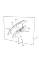
図1は、第1のパチンコ遊技機を前方向右斜め上から見たときの外観を示す斜視図の一例である。図2は、第1のパチンコ遊技機を前方向右斜め上から見たときの分解斜視図の一例である。図3は、第1のパチンコ遊技機を後方向右斜め上から見たときの外観を示す斜視図の一例である。
[1-1. Exterior configuration]
FIG. 1 is an example of a perspective view showing the appearance of the first pachinko game machine when viewed diagonally from above and to the right in the front direction. FIG. 2 is an example of an exploded perspective view of the first pachinko game machine when viewed diagonally from above and to the right in the front direction. FIG. 3 is an example of a perspective view showing the appearance of the first pachinko game machine when viewed diagonally from above and to the right in the rear direction.
[1-1-1.基本構成]
図1~図3に示されるように、第1のパチンコ遊技機は、外枠2、ベースドア3、ガラスドア4、皿ユニット5、発射装置6、表示装置7(図2参照)、払出ユニット8(図2、図3参照)、基板ユニット9(図2、図3参照)、および、遊技盤ユニット10(図2参照)等を備える。さらに、遊技盤ユニット10の右下部にはLEDユニット160(図2参照)が設けられている。ここでは、外枠2、ベースドア3、ガラスドア4、皿ユニット5、発射装置6、表示装置7、払出ユニット8および基板ユニット9について簡単に説明し、遊技盤ユニット10およびLEDユニット160についての詳細を後述する。なお、上記の括弧書きは、図1に図示がない構成についての参照図面を示している。
[1-1-1. Basic configuration]
As shown in FIGS. 1 to 3, the first pachinko game machine includes an
(外枠)
外枠2は、正面視略矩形状の枠体であり、前後方向に貫通する開口21を有する。この外枠2は、遊技場の島設備に固定して取り付けられる。外枠2の例えば左端部の前側には蝶番(参照符号なし)が設けられており、この蝶番には、ベースドア3が軸支されている。このようにすることで、蝶番を軸として外枠2に対してベースドア3を前方に回動させることが可能となっている。
(outer frame)
The
なお、外枠2は、ベースドア3を介して、後述する払出ユニット8、基板ユニット9、表示装置7、遊技盤ユニット10、ガラスドア4および皿ユニット5等の多数の部材を支持するため、高い強度が必要とされる。その一方で、演出効果を高めることを目的として例えば表示装置7(図2参照)や遊技盤ユニット10の大型化が要求されている。そのため、外枠2を例えば薄板の金属で構成することにより、表示装置7や遊技盤ユニット10の大型化を図りつつ、高い強度を保つことができる。とくに外枠2をアルミ製にすれば、軽量化を図ることも可能となる。
Note that the
(ベースドア)
ベースドア3は、裏面側に例えば払出ユニット8および基板ユニット9等が取り付けられており、これらを支持している。
(base door)
The
ベースドア3の表面側には遊技盤ユニット10がはめ込まれる。また、ベースドア3の例えば左端部の前側には、上端部、上下方向略中央部よりも下方側の中途部、および、下端部のそれぞれに蝶番(参照符号なし)が設けられており、上端部および中途部の蝶番にガラスドア4が軸支され、中途部および下端部の蝶番に皿ユニット5がそれぞれ軸支されている。このようにすることで、蝶番を軸としてベースドア3に対してガラスドア4および皿ユニット5を一体でまたは個別に前方に回動させることが可能となっている。
A
また、ベースドア3の表面側の例えば右側下方には発射装置6が固定して取り付けられており、例えば上方側の左右のそれぞれには、スピーカ32(図2参照)が固定して取り付けられている。このスピーカ32からは、例えば、表示装置7に表示されるキャラクタ等の音声演出、楽曲、効果音、音声による告知、エラー報知等の演出音等が出力される。
Further, a
さらに、ベースドア3の蝶番と反対側(すなわち右端部)には、施錠装置(不図示)が設けられている。この施錠装置は、外枠2に対してベースドア3を施錠したり、ベースドア3に対してガラスドア4を施錠したりする機能を備えている。
Further, a locking device (not shown) is provided on the opposite side of the
(ガラスドア)
ガラスドア4は、開口41が形成された枠状の部材である。この開口41には、透過性を有する保護ガラス43(図2参照)が後面側から取り付けられている。ガラスドア4がベースドア3に対して閉じられると、遊技盤ユニット10に形成される遊技領域105(後述の図4参照)と保護ガラス43とが対向する。このようにして、ガラスドア4がベースドア3に対して閉じられた状態で遊技領域105を前方から視認することができるとともに、遊技領域105を流下する遊技球が前方に飛び出さないようにすることができる。
(glass door)
The
なお、保護ガラス43は、複数枚(例えば2枚)のガラスを互いに間隙を有して取り付けるものであってもよいし、互いに間隙を有するように複数枚のガラスがユニット化されたものであってもよい。さらには、ユニット化されたものである場合、ガラスとガラスとの間に例えば導光板が備えられたものであってもよい。上記の保護ガラス43は、ガラス製に限られず、例えば透明樹脂製であってもよい。
Note that the
また、ガラスドア4の下部には、遊技情報提供サービス(例えば、「ユニメモ(登録商標)」)の提供を受けるために例えば遊技者が操作することが可能な操作部66が設けられる。この操作部66は、遊技場の管理者等がホールメニュー画面上で操作することが可能な操作部として機能させることもできる。
Further, at the bottom of the
また、ガラスドア4の上部には、上述したスピーカ32の前方に配置されるスピーカカバー45が設けられている。さらに、ガラスドア4の開口41の周縁部には、発光演出等に用いられる多数のLED群46が配置されており、これらのLED群46の前方にはLEDカバーが設けられている。図1および図2において図示される符号46は、厳密にいえばLEDカバーであるが、便宜上、LED群46として説明する。LED群46は、例えば、光での告知や、さまざまなバリエーションで発光演出等を行う演出用の発光手段であるが、このような発光演出等を実行できればLEDに限られず、例えば液晶やランプ等であってもよい。
Furthermore, a
(皿ユニット)
皿ユニット5は、上皿51と下皿52とをユニット化したものである。皿ユニット5は、ベースドア3の前下部であって、ガラスドア4の下方に配置される。この皿ユニット5は、例えば球詰まり等の発生時に遊技場の店員等が球詰まりを解消できるように、上述したとおり、ベースドア3に対して回動させて開閉できるように構成されている。なお、皿ユニット5は、必ずしも上皿51と下皿52とをそれぞれ設ける必要はなく、一体皿として構成してもよい。
(Plate unit)
The
上皿51は、遊技球を貯留可能に設けられており、上皿51に貯留された遊技球は、発射装置6から遊技領域105(後述の図4参照)に向けて発射される。上皿51には、払出口53および演出ボタン54等が設けられる。貸し出される遊技球や賞球として払い出される遊技球は、払出口53から上皿51に払い出される。演出ボタン54は、所謂「CHANCEボタン」や、「プッシュボタン」等と呼ばれるものである。演出ボタン54は、遊技者によって操作される操作機能の他、所定の演出機能を有してもよい。所定の演出機能としては、例えば特別図柄の当り判定処理の結果に基づいて振動したり上方に突出するような機能が相当する。また、上記操作部66の機能を兼用するようにしてもよい。
The
下皿52は、主として上皿51から溢れた遊技球を貯留するためのものである。下皿52には上皿51と連通する払出口55が設けられており、上皿51から溢れた遊技球は払出口55から下皿52に払い出される。
The
下皿52の底面には、遊技者の操作によって開閉させることが可能な開口部(参照符号なし)が形成されている。下皿52の底面に形成された開口部を開状態にすると、下皿52に貯留されている遊技球を、下皿52の下方に載置された球箱に移すことができる。なお、所謂各台計数システムが各台に設けられている場合、球箱を必要としないだけでなく、各台計数システムで計数された遊技球を貯球し、貯球された遊技球を再び遊技に供することもできる。
An opening (no reference numeral) is formed in the bottom of the
(発射装置)
発射装置6は、上皿51に貯留された遊技球を、遊技領域105(後述の図4参照)に向けて発射するためのものである。発射装置6は、ベースドア3の前右下部であって、皿ユニット5の右下方に配置される。発射装置6は、パネル体61、駆動装置(不図示)および発射ハンドル62を備える。
(launching device)
The
パネル体61は、ベースドア3に対し皿ユニット5が閉じられた状態において、皿ユニット5と、ベースドア3に固定して取り付けられた発射装置6とが外観上一体となるように設けられる。
The
発射ハンドル62は、右回りまたは左回りに回動可能に構成されており、パネル体61の表面側に配置される。上記の駆動装置は、パネル体61の裏面側に配置され、例えば発射ソレノイド(図示せず)により構成される。遊技者によって発射ハンドル62が操作されると、駆動装置の動作により遊技球が発射される。なお、発射ハンドル62を操作する際に、右回りへの回動量(操作量)が大きいほど遊技球の発射強度が強くなる。
The firing handle 62 is configured to be rotatable clockwise or counterclockwise, and is arranged on the front side of the
皿ユニット5の右下方に配置された発射装置6から発射された遊技球は、発射レール(不図示)を経てガイドレール110(後述の図4参照)に沿って円弧状に転動して遊技領域105(後述の図4参照)に打ち出される。なお、発射装置6の配置位置は、皿ユニット5の右下方に限られず、皿ユニット5の左下方であってもよい。この場合、上記の発射レールが不要となり、ガラスドア4の下方の領域を有効に利用することができ、汎用性を高めることが可能となる。
A game ball fired from a
(表示装置)
表示装置7(図2参照)は、遊技に関する各種の演出画像を表示する表示領域を有するものであって、遊技パネル100の開口に上記の表示領域が臨むように取り付けられる。表示装置7は、例えば、液晶表示装置、7セグ表示装置、ドットマトリクス表示装置、エレクトロルミネッセンスで構成される表示装置等であってもよいし、プロジェクタ等の投影装置を用いて映像を投影するものであってもよい。表示装置7の表示領域には、例えば、演出用識別図柄(例えば、装飾図柄)を可変表示させて特別図柄の当り判定処理の結果を表示したり、特別図柄の当り判定処理の結果に応じた演出画像、大当り遊技状態中の演出画像、デモ演出画像、特別図柄の可変表示の保留状況を示す演出画像等が表示される。本実施例では、表示装置7が遊技盤ユニット10に取り付けられているが、表示装置7の表示領域が遊技パネル100の開口に臨むように配置されていれば、表示装置7はベースドア3に取り付けられるようにしてもよい。
(display device)
The display device 7 (see FIG. 2) has a display area for displaying various performance images related to the game, and is attached so that the display area faces the opening of the
なお、本実施例では、上記各種の演出画像を表示するものとして一つの表示装置7を備えているが、複数(例えば二つ)の表示装置を設けて、これら複数の表示装置を用いて演出画像を表示するようにしても良い。
In this embodiment, one
(払出ユニット)
払出ユニット8(図2、図3参照)は、ベースドア3の背面側に配置されており、球通路81、払出装置82等で構成される。球通路81には、貯留タンク80(図2、図3参照)から遊技球が供給される。なお、貯留タンク80には、島設備(不図示)から遊技球が供給される。払出装置82は、払出条件が成立すると、貯留タンク80から球通路81に供給された遊技球のうち所定個数の遊技球を例えば上皿51に払い出す。また、払出ユニット8の背面側には、図3に示されるように電源スイッチ95が設けられる。
(Payout unit)
The dispensing unit 8 (see FIGS. 2 and 3) is arranged on the back side of the
(基板ユニット)
基板ユニット9(図2、図3参照)は、ベースドア3の背面側に配置される。基板ユニット9には、各種制御基板等が設けられる。
(board unit)
The board unit 9 (see FIGS. 2 and 3) is arranged on the back side of the
具体的には、図3に示されるように、主制御回路200(後述の図6参照)が実装された主制御基板91、サブ制御回路300(後述の図6参照)が実装されたサブ制御基板92、遊技球の払出・発射を制御する払出・発射制御回路400(後述の図6参照)が実装された払出・発射制御基板93、および、電源を供給する電源供給回路450(後述の図6参照)が実装された電源供給基板等が基板ユニット9に設けられている。
Specifically, as shown in FIG. 3, a
なお、図3では、便宜上、主制御基板91、サブ制御基板92、払出・発射制御基板93および電源供給基板94を参照符号として示しているが、これらの基板は、全て、基板ケースに収容されている。
In addition, in FIG. 3, for convenience, the
また、本実施例では、サブ制御基板92を、ワンボード基板(1つの基板に1つの制御LSIまたは複数のLSIが設けられた基板)として構成する。ただし、これに限られず、例えば、後述する表示制御回路304、音声制御回路305、LED制御回路306および役物制御回路307(いずれも後述の図6参照)等の全部または一部を別個の基板とすることで、サブ制御基板92を複数の基板で構成してもよい。
Further, in this embodiment, the
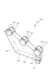
[1-1-2.遊技盤ユニット]
図4は、第1のパチンコ遊技機が備える遊技盤ユニット10の外観を示す正面図の一例である。
[1-1-2. Game board unit]
FIG. 4 is an example of a front view showing the appearance of the
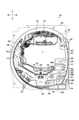
図4に示されるように、遊技盤ユニット10は、主として、発射された遊技球が転動流下可能な遊技領域105が形成される遊技パネル100と、ガイドレール110と、遊技領域105の略中央部に配置されるセンター役物115と、第1始動口120と、一般入賞口122と、通過ゲートユニット125と、特別電動役物ユニット130と、第2始動口140A,140Bと、普通電動役物ユニット145と、小当りユニット150と、LEDユニット160と、アウト口178と、遊技盤ユニット10の後方に配置される裏ユニット(図示せず)とを備える。なお、上述したとおり、LEDユニット160については後述する。
As shown in FIG. 4, the
(遊技パネル)
遊技パネル100には、表示装置7の表示領域が臨む位置に開口(参照符号なし)が形成されている。また、遊技パネル100の前面には、ガイドレール110が設けられるとともに遊技釘(参照符号なし)等が植設されている。発射装置6(図1、図2参照)から発射された遊技球は、ガイドレール110から遊技領域105に向けて飛び出し、遊技釘等と衝突して進行方向を変えながら遊技領域105の下方に向けて流下する。
(Game panel)
An opening (no reference numeral) is formed in the
また、遊技パネル100の後方には、演出効果を高めるために装飾体が設けられた裏ユニット(図示せず)が配置されている。遊技パネル100は、裏ユニットに設けられた装飾体を正面視で視認できるように透明樹脂で構成されている。この場合、遊技パネル100の全部が透明部材で構成されていてもよいし、例えば、裏ユニットに設けられた装飾体を正面視で視認できる部位のみが透明部材で構成されていてもよい。また、遊技パネル100を、透明部分を有さない部材(例えば木製)で構成し、一部に透明部材を設けて演出効果を高めるようにしてもよい。
Further, behind the
なお、本実施例では、裏ユニットを正面視で視認できるように遊技パネル100が透明樹脂で構成されているが、遊技パネル100の全部を透明としてもよいし、一部のみを透明としてもよい。
In this embodiment, the
(ガイドレール)
ガイドレール110は、円弧状の外レールおよび内レール(いずれも参照符号なし)により構成される。遊技領域105は、ガイドレール110によって区画(画定)される。外レールおよび内レールは、発射装置6から発射された遊技球を遊技領域105の上部に案内する機能を有する。
(guide rail)
The
(センター役物)
センター役物115は、遊技パネル100の開口にはめ込まれるように構成されており、上方には円弧状のセンターレール116を備えている。遊技領域105に向けて発射された遊技球は、センターレール116によって左右に振り分けられる。
(center role)
The
この第1のパチンコ遊技機において、遊技領域105のうち、センター役物115よりも左側の領域を左側領域106と称し、センター役物115よりも右側の領域を右側領域107と称する。左側領域および右側領域の定義は、後述する第2のパチンコ遊技機および第3のパチンコ遊技機についても同様である。
In this first pachinko game machine, in the
発射装置6によって遊技領域105に向けて発射された遊技球は、左側領域106または右側領域107を流下する。左側領域106または右側領域107を流下する遊技球は、遊技パネル100に植設された遊技釘等との衝突により、進行方向を変えながら下方へ向けて流下する。発射ハンドル62の操作量が小さい場合、発射された遊技球は左側領域106を流下する。一方、発射ハンドル62の操作量が大きい場合、発射された遊技球は右側領域107を流下する。
The game ball fired toward the
なお、この明細書において、発射ハンドル62の操作態様(打ち方)として、左側領域106を流下するように遊技球を発射させる打ち方を「左打ち」と称し、右側領域107を流下するように遊技球を発射させる打ち方を「右打ち」と称する。このように、遊技者によって左側領域106または右側領域107に向けて遊技球を打ち分け可能とされている。
In addition, in this specification, as an operation mode (hitting method) of the
また、センター役物115には、左側の外周縁部に、左側領域106を流下する遊技球が進入可能とされたワープ入口117が形成されている。ワープ入口117に進入した遊技球は、センター役物115に形成されたステージ118に誘導可能に構成されている。ステージ118は、表示装置7の表示領域の下方前方において遊技球が左右方向に転動可能に形成されている。なお、ステージ118は、例えば、上段側のステージおよび下段側のステージといったように、複数段で形成されていてもよい。
In addition, the
ステージ118の左右方向略中央の後側には、遊技球が進入可能なチャンス入口119が形成されており、チャンス入口119に進入した遊技球は、第1始動口120の直上に放出されるように構成されている。そのため、チャンス入口119に進入した遊技球は、ワープ入口117に進入しなかった遊技球や、ワープ入口117に進入したもののチャンス入口119に進入しなかった遊技球と比べて高い確率で第1始動口120に入賞(通過)するようになっている。
A
(第1始動口)
第1始動口120は、表示装置7の表示領域の下方に配置されており、左打された遊技球が入賞可能(右打ちされた遊技球が入賞困難または不可能)となるように配置されている。第1始動口120に遊技球が入賞すると、第1始動口スイッチ121(後述の図6参照)により検出される。なお、右打ちされた遊技球が第1始動口120に入賞可能であってもよい。また、上記の第1始動口120に代えてまたは加えて、右打ちされた遊技球が入賞可能(左打ちされた遊技球が入賞困難または不可能)な第1始動口を備えるようにしてもよい。
(1st starting port)
The
第1始動口スイッチ121(後述の図6参照)により第1始動口120への遊技球の入賞(通過)が検出されると、第1特別図柄にかかる各種データ(例えば、第1特別図柄の大当り判定用乱数値、第1特別図柄の図柄乱数値、第1特別図柄のリーチ判定用乱数値、および、第1特別図柄の演出選択用乱数値等の各種乱数値等)が抽出され、抽出された各種データは所定数(例えば最大4個)まで記憶される。記憶された各種データは、始動条件が成立すると、第1特別図柄の当り判定処理に供される。第1始動口120に遊技球が入賞すると例えば3個の賞球が払い出される。ただし、第1始動口120への遊技球の入賞に基づいて払い出される賞球数はこれに限られない。
When the winning (passing) of a game ball to the
この明細書において、第1始動口120への遊技球の入賞を第1特別図柄の始動入賞と称し、第1特別図柄にかかる各種データ(例えば、第1特別図柄の大当り判定用乱数値、第1特別図柄の図柄乱数値、第1特別図柄のリーチ判定用乱数値、および、第1特別図柄の演出選択用乱数値等の各種乱数値等)を第1特別図柄の始動情報と称する。また、始動条件が成立するまで第1特別図柄の始動情報を記憶することを保留と称し、保留されている第1特別図柄の始動情報を「第1特別図柄の保留球」とも称する。第2特別図柄についても同様である。 In this specification, the winning of a game ball into the first starting opening 120 is referred to as the starting winning of the first special symbol, and various data related to the first special symbol (for example, the random number value for jackpot determination of the first special symbol, the Various random values such as the random number value of the first special symbol, the random number value for reach determination of the first special symbol, the random number value for performance selection of the first special symbol, etc.) are referred to as starting information of the first special symbol. Further, storing the starting information of the first special symbol until the starting condition is satisfied is called "holding", and the starting information of the first special symbol being held is also called "the reserved ball of the first special symbol". The same applies to the second special symbol.
(一般入賞口)
一般入賞口122は、遊技領域105の左下方に複数配置されており、左打された遊技球が入賞可能(右打ちされた遊技球が入賞困難または不可能)となるように配置されている。一般入賞口122に遊技球が入賞すると、一般入賞口スイッチ123(後述の図6参照)により検出される。
(General prize opening)
A plurality of general winning
一般入賞口スイッチ123(後述の図6参照)により一般入賞口122への遊技球の入賞(通過)が検出されると、例えば4個の賞球が払い出されるが、一般入賞口122への遊技球の入賞に基づいて払い出される賞球数は4個に限られない。
When the general winning hole switch 123 (see FIG. 6 described later) detects that a game ball enters (passes) the general winning
また、本実施例において、一般入賞口122は、右打ちされた遊技球が入賞困難または不可能となるように配置されているが、必ずしもこれに限られず、上記の一般入賞口122に代えてまたは加えて、右打ちされた遊技球が入賞可能な一般入賞口を備えてもよい。
In addition, in this embodiment, the general winning
(通過ゲートユニット)
通過ゲートユニット125は、右側領域107に配置されており、右打ちされた遊技球がほぼ通過できるように構成された通過ゲート126と、通過ゲート126への遊技球の通過を検出する通過ゲートスイッチ127(後述の図6参照)とを一体化したユニット体である。
(passing gate unit)
The
通過ゲートスイッチ127により通過ゲート126への遊技球の通過が検出されると、普通図柄にかかる各種データ(例えば、普通図柄の当り判定用乱数値等)が抽出され、抽出された各種データは所定数(例えば最大4個)まで記憶される。記憶された各種データは、普通図柄の当り判定処理に供される。なお、通過ゲートスイッチ127により通過ゲートユニット125への遊技球の通過が検出されたとしても、賞球は払い出されない。また、通過ゲートユニット125は、右側領域107に代えてまたは加えて左側領域106に配置されていてもよい。
When the passage of the game ball to the
また、通過ゲート126を、役物連続作動装置を作動させるための契機となるように機能させてもよい。すなわち、大当りでない遊技状態(例えば通常遊技状態等)から大当り遊技状態への移行条件は、条件装置および役物連続作動装置の両方が作動することであるが、大当りであることを示す停止表示態様(図柄組合せ)が導出された際に、条件装置については作動させるものの役物連続作動装置については作動させないようにすることができる。そして、条件装置が作動していることを前提として、通過ゲート126への遊技球の通過すなわち通過ゲートスイッチ127(後述の図6参照)により遊技球が検出されたことをもって役物連続作動装置を作動させて、大当り遊技状態に移行するようにしてもよい。
Further, the
この明細書において、通過ゲート126への遊技球の通過を始動通過と称し、通過ゲート126への遊技球の通過によって抽出された普通図柄にかかる各種データ(例えば、普通図柄の当り判定用乱数値等)を普通図柄の始動情報と称する。また、始動条件が成立するまで普通図柄の始動情報を記憶することを保留と称し、保留されている普通図柄の始動情報を「普通図柄の保留球」とも称する。
In this specification, the passage of the game ball to the
(特別電動役物ユニット)
特別電動役物ユニット130は、大当り用大入賞口131と、大当り用大入賞口131への遊技球の入賞(通過)を検出する大当り用大入賞口カウントスイッチ132(後述の図6参照)と、特別電動役物133とを一体化したユニット体である。特別電動役物ユニット130は、遊技領域105内の略右下部であって、通過ゲートユニット125よりも下方に配置されている。
(Special electric accessory unit)
The special electric
大当り用大入賞口131は、右打ちされた遊技球が入賞可能(左打ちされた遊技球が入賞困難または不可能)となるように配置されている。ただし、これに限定されるものではなく、上記の大当り用大入賞口131に代えてまたは加えて、左打ちされた遊技球が入賞可能な大当り用大入賞口を配置したり、センター役物115の上部において遊技球が入賞可能な大当り用大入賞口を配置するようにしてもよい。
The jackpot
また、大当り用大入賞口131は、遊技者に有利な遊技状態である大当り遊技状態に制御されているときに所定個数(例えば10個)の遊技球が入賞(通過)可能となるように開放される入賞口である。大当り用大入賞口カウントスイッチ132(後述の図6参照)により大当り用大入賞口131への遊技球の入賞が検出されると、例えば10個の賞球が払い出される。ただし、大当り用大入賞口131への遊技球の入賞に基づいて払い出される賞球数は10個に限られない。
In addition, the
特別電動役物133は、前後方向に進退可能な特電用シャッタ134と、この特電用シャッタ134を作動させる特電用ソレノイド135(後述の図6参照)とを備える。特別電動役物133すなわち特電用シャッタ134は、大当り用大入賞口131への遊技球の入賞(通過)が可能または容易な開放状態と、大当り用大入賞口131への遊技球の入賞(通過)が不可能または困難な閉鎖状態と、に状態移行可能に構成される。なお、大当り用大入賞口131の閉鎖状態から開放状態への状態移行は、所定のラウンド数にわたって行われる。すなわち、大当り遊技状態は、大当り用大入賞口131が閉鎖状態から所定期間にわたって開放状態に移行するラウンド遊技を複数ラウンドにわたって行うことにより、多量の遊技球を賞球として払い出すことを可能にした遊技状態である。
The special
(第2始動口)
本実施例では、第2始動口として、第2始動口140Aおよび第2始動口140Bが遊技領域105に配置されており、これらの第2始動口140A,140Bは、いずれも、右打された遊技球が入賞可能(左打ちされた遊技球が入賞困難または不可能)となっている。ただし、これに限られず、左打ちされた遊技球が第2始動口140Aまたは/および第2始動口140Bに入賞可能であってもよい。
(Second starting port)
In this embodiment, as second starting ports, a
第2始動口140Aに遊技球が入賞すると、第2始動口スイッチ141A(後述の図6参照)により検出される。また、第2始動口140Bに遊技球が入賞すると、第2始動口スイッチ141B(後述の図6参照)により検出される。第2始動口140A,140Bのいずれに遊技球が入賞したとしても、第2特別図柄の当り判定処理の契機となる。
When a game ball enters the
第2始動口スイッチ141A,141B(後述の図6参照)により第2始動口140A,140Bへの遊技球の入賞(通過)が検出されると、第2特別図柄の始動情報が抽出され、抽出された始動情報は所定数(例えば最大4個)まで保留される。保留された始動情報は、第2特別図柄の当り判定処理に供される。第2始動口140Aに遊技球が入賞すると例えば3個の賞球が払い出される。一方、第2始動口140Bに遊技球が入賞すると例えば1個の賞球が払い出される。ただし、第2始動口140A,140Bへの遊技球の入賞に基づいて払い出される賞球数はこれに限られない。
When the second starting port switches 141A, 141B (see FIG. 6 described later) detect winning (passing) of the game ball to the
ところで、本実施例では、右打ちされたものの大当り用大入賞口131に入賞しなかった遊技球の流下方向としての下流側には、遊技球の流下経路として上下に2つの流下経路107a,107bが形成されている。右打ちされて大当り用大入賞口131に入賞せずにさらに下流側に向けて流下した遊技球は、例えば図4に示される分岐釘108によって、上方の流下経路107aまたは下方の流下経路107bに振り分けられる。
By the way, in this embodiment, on the downstream side as the flowing direction of the game ball that was hit to the right but did not enter the
第2始動口140Aは、上方の流下経路107aに振り分けられた遊技球が入賞可能に配置されており、上方の流下経路107aを流下する遊技球の殆どが入賞可能となっている。ただし、上方の流下経路107aを流下する遊技球の殆どが第2始動口140Aに入賞するように構成することは必須ではなく、例えば、第2始動口140Aへの入賞が殆ど期待できない構成であってもよいし、上方の流下経路107aを流下する遊技球のうち所定の期待値(例えば、概ね3分の1~5分の1)で入賞可能な構成であってもよい。なお、上方の流下経路107aを流下したものの第2始動口140Aに入賞しなかった遊技球は、アウト口178から機外に排出されるように構成されている。
The
第2始動口140Bは、下方の流下経路107bに振り分けられた遊技球が入賞可能に配置されているが、その詳細については普通電動役物ユニット145の説明において後述する。
The
(普通電動役物ユニット)
普通電動役物ユニット145は、下方の流下経路107b側に配置されており、遊技球が入賞(通過)することによって所定数の遊技球が賞球として払い出される入賞口と、この入賞口への遊技球の入賞を検出するスイッチと、普通電動役物146とを一体化したユニット体である。本実施例では、上記の入賞口を第2始動口140Bとし、上記のスイッチを第2始動口スイッチ141Bとしている。ただし、上記の入賞口を第2始動口140Bとすることは必須ではなく、例えば第1始動口を上記の入賞口としてもよい。
(Normal electric accessory unit)
The normal
普通電動役物146は、前後方向に進退可能な普電用シャッタ147と、この普電用シャッタ147を作動させる普電用ソレノイド148(後述の図6参照)とを備える。普通電動役物146すなわち普電用シャッタ147は、第2始動口140Bへの遊技球の入賞(通過)が可能または容易な開放状態と、第2始動口140Bへの遊技球の入賞が不可能または困難な閉鎖状態と、に状態移行可能に構成される。なお、前後方向に進退可能な上記の普電用シャッタ147に代えて、所謂電動チューリップと呼ばれる例えば一対の羽根部材からなる可動部材を採用してもよい。また、可動部材は、一対に限られず、羽根型、扉型、突出板型等を含む。
The normal
(小当りユニット)
小当りユニット150は、小当り用大入賞口151と、小当り用大入賞口151への遊技球の入賞(通過)を検出する小当り用大入賞口カウントスイッチ152(後述の図6参照)と、前後方向に進退可能な小当り用シャッタ153と、この小当り用シャッタ153を作動させることが可能な小当り用ソレノイド154とを一体化したユニット体である。
(Small winning unit)
The
小当り用シャッタ153は、前後方向に進退させることで、小当り用大入賞口151への遊技球の入賞(通過)が可能または容易な開放状態と、小当り用大入賞口151への遊技球の入賞が不可能または困難な閉鎖状態と、に状態移行可能に構成される。
By moving forward and backward in the front and back direction, the small winning
小当り用大入賞口151が開放されたときに遊技球が入賞すると、入賞した遊技球が小当り用大入賞口カウントスイッチ152(後述の図6参照)に検出される。小当り用大入賞口カウントスイッチ152に遊技球が検出されると、例えば10個の賞球が払い出される。ただし、小当り用大入賞口151への遊技球の入賞に基づいて払い出される賞球数は10個に限られない。
When a game ball wins when the small winning large winning
また、小当りユニット150は、下方の流下経路107bであって普通電動役物ユニット145の下流側に配置されている。したがって、普通電動役物146の作動によって第2始動口140Bが開放されている場合、たとえ小当り用大入賞口151が開放されていたとしても、下方の流下経路107bを流下した遊技球は小当り用大入賞口151に到達する前に、上流側に設けられる第2始動口140Bに入賞するため、小当り用大入賞口151に入賞することが困難(または不可能)となる。
Further, the small winning
なお、本実施例では、大当り用大入賞口131と小当り用大入賞口151とをそれぞれ別に設けているが、これに限られず、大当り遊技制御処理の実行時に開放される大入賞口と、小当り遊技制御処理の実行時に開放される大入賞口とを、同じ大入賞口としてもよい。
In addition, in this embodiment, the large winning
(アウト口)
アウト口178は、遊技領域105に向けて発射されたものの各種入賞口(例えば、第1始動口120、第2始動口140A,140B、大当り用大入賞口131、一般入賞口122等)のいずれにも入賞しなかった遊技球を、機外に排出するためのものである。このアウト口178は、左打ちされた遊技球および右打ちされた遊技球のいずれについても機外に排出できるように、遊技領域105の最下流側に設けられている。ただし、上記のアウト口178に加えて、最下流側でない位置、例えば複数の一般入賞口122の間や普通電動役物ユニット145と小当りユニット150との間等にアウト口を設けて、遊技領域105を流下中の遊技球を機外に排出するようにしてもよい。
(Out port)
The out
(裏ユニット)
裏ユニット(不図示)は、装飾体を有するものであって、上述したように、透過性のある遊技パネル100の後方側に設けられる。この裏ユニットは、サブ制御回路300(後述の図6参照)によって制御される可動役物等の演出用役物群58を備える。演出用役物群58は、表示装置7の表示領域の周囲に配置される。これらの演出用役物群58のうち少なくとも一以上の役物または役物を構成する演出用役物構成部材は、特別図柄の当り判定処理の結果にもとづいて動作可能な演出用役物として機能する。
(back unit)
The back unit (not shown) has a decorative body, and is provided on the rear side of the
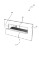
[1-1-3.LEDユニット]
LEDユニット160は、遊技盤ユニット10の右下部であって、遊技領域105の外側に配置される(図4、図5参照)。LEDユニット160は、各種の表示部を一体化したユニット体である。
[1-1-3. LED unit]
The
図5は、第1のパチンコ遊技機が備えるLEDユニット160を示す正面図の一例である。
FIG. 5 is an example of a front view showing the
図5に示されるように、LEDユニット160は、普通図柄表示部161、普通図柄用保留表示部162、第1特別図柄表示部163、第2特別図柄表示部164、第1特別図柄用保留表示部165、および、第2特別図柄用保留表示部166を備える。
As shown in FIG. 5, the
(普通図柄表示部)
普通図柄表示部161は、普通図柄の当り判定処理の結果を表示するものであって、普通図柄表示LED161a,161bを備える。普通図柄の可変表示を開始するための条件(以下、「普通図柄の始動条件」と称する)が成立すると、普通図柄表示LED161a,161bが交互に点灯・消灯を繰り返す普通図柄の可変表示が開始される。普通図柄の可変表示が開始されてから所定時間が経過すると、普通図柄の可変表示が停止し、普通図柄の当り判定処理の結果が導出される。
(Normal symbol display section)
The normal
普通図柄の当り判定処理の結果が普通図柄当りである場合、普通図柄表示LED161a,161bの点灯・消灯の組み合わせが特定の停止表示態様となる。例えば、普通図柄の当り判定処理の結果が普通図柄当りである場合、普通図柄表示LED161aが点灯するとともに普通図柄表示LED161bが消灯する。一方、普通図柄の当り判定処理の結果がハズレである場合、例えば、普通図柄表示LED161aが消灯するとともに普通図柄表示LED161bが点灯する。ただし、普通図柄の当り判定処理の結果を示す普通図柄表示LED161a,161bの停止表示態様はこれに限られない。そして、普通図柄が特定の停止表示態様で停止表示されると、普通電動役物146を作動させることが決定し、普電用シャッタ147が所定のパターンで開閉駆動し、第2始動口140Bへの遊技球の入賞(通過)が容易となる。
When the result of the normal symbol hit determination process is a normal symbol hit, the combination of lighting and extinguishing of the normal
(普通図柄用保留表示部)
普通図柄用保留表示部162は、普通図柄の可変表示が保留されている場合、保留されている普通図柄の可変表示の数(以下、「普通図柄の保留数」と称する)を表示するものであって、普通図柄用保留表示LED162a,162bを備える。上記の「普通図柄の可変表示が保留されている」とは、通過ゲート126への遊技球の通過が検出されて普通図柄にかかる各種データ(例えば、普通図柄の当り判定用乱数値等)が抽出されてから、普通図柄の始動条件が成立するまでの状態をいう。なお、普通図柄の始動条件は、普通図柄が可変表示中でないこと、および、普通図柄の可変表示が保留されていること、を少なくとも全て満たす場合に成立する。
(Regular symbol reservation display section)
The normal symbol pending
普通図柄用保留表示部162は、普通図柄用保留表示LED162a,162bの点灯・消灯の組み合わせによって普通図柄の可変表示の保留数を表示する。例えば、普通図柄の保留数が1個である場合、普通図柄用保留表示LED162aが点灯するとともに普通図柄用保留表示LED162bが消灯する。また、普通図柄の保留数が2個である場合、普通図柄用保留表示LED162a,162bの両方が点灯する。また、普通図柄の保留数が3個である場合、普通図柄用保留表示LED162aが点滅するとともに普通図柄用保留表示LED162bが点灯する。さらに、普通図柄の保留数が4個である場合、普通図柄用保留表示LED162a,162bの両方が点滅する。ただし、普通図柄の保留数を示す普通図柄用保留表示LED162a,162bの表示態様はこれに限られない。
The normal symbol holding
(特別図柄表示部)
特別図柄表示部は、特別図柄の当り判定処理の結果を表示するものであって、第1特別図柄表示部163および第2特別図柄表示部164を備える。第1特別図柄表示部163は、例えば8個のLEDからなる第1特別図柄表示LED群163aを備える。同様に、第2特別図柄表示部164も、例えば8個のLEDからなる第2特別図柄表示LED群164aを備える。
(Special pattern display section)
The special symbol display section displays the result of the special symbol hit determination process, and includes a first special
第1特別図柄の可変表示を開始するための条件(以下、「第1特別図柄の始動条件」と称する)が成立すると、第1特別図柄表示LED群163aが交互または相互に点灯・消灯を繰り返す第1特別図柄の可変表示が開始される。第1特別図柄の可変表示が開始されてから所定時間が経過すると、第1特別図柄の可変表示が停止し、第1特別図柄の当り判定処理の結果が導出される。
When the conditions for starting variable display of the first special symbol (hereinafter referred to as "starting conditions for the first special symbol") are satisfied, the first special symbol
第1特別図柄の当り判定処理の結果が大当りである場合、第1特別図柄表示部163を構成する第1特別図柄表示LED群163a(例えば8個のLED)の点灯・消灯の組み合わせが特定の停止表示態様となる。そして、第1特別図柄表示部163が特定の停止表示態様で停止表示されると、大当り遊技状態への移行が決定する。
When the result of the hit determination process for the first special symbol is a jackpot, the combination of lighting and extinguishing of the first special symbol
第2特別図柄の可変表示を開始するための条件(以下、「第2特別図柄の始動条件」と称する)が成立すると、第2特別図柄表示LED群164aが交互または相互に点灯・消灯を繰り返す第2特別図柄の可変表示が開始される。第2特別図柄の可変表示が開始されてから所定時間が経過すると、第2特別図柄の可変表示が停止し、第2特別図柄の当り判定処理の結果が導出される。
When the conditions for starting variable display of the second special symbol (hereinafter referred to as "second special symbol starting conditions") are met, the second special symbol
第2特別図柄の当り判定処理の結果が大当りである場合、第2特別図柄表示部164を構成する第2特別図柄表示LED群164a(例えば8個のLED)の点灯・消灯の組み合わせが特定の停止表示態様となる。そして、第2特別図柄表示部164が特定の停止表示態様で停止表示されると、大当り遊技状態への移行が決定する。
When the result of the second special symbol hit determination process is a jackpot, the combination of lighting and extinguishing of the second special symbol
(特別図柄用保留表示部)
特別図柄用保留表示部は、特別図柄の可変表示が保留されている場合、保留されている特別図柄の可変表示の数(以下、「特別図柄の保留数」と称する)を表示するものであって、第1特別図柄用保留表示部165および第2特別図柄用保留表示部166を備える。
(Special design reservation display section)
The special symbol reservation display section is for displaying the number of reserved variable displays of special symbols (hereinafter referred to as the "number of reserved special symbols") when variable displays of special symbols are reserved. A first special symbol
第1特別図柄用保留表示部165は、第1特別図柄の可変表示が保留されている場合、第1特別図柄の保留数を表示するものであって、第1特別図柄用保留表示LED165a,165bを備える。「第1特別図柄の可変表示が保留されている」とは、第1始動口120への遊技球の入賞(通過)が検出されて第1特別図柄にかかる各種データ(例えば、第1特別図柄の大当り判定用乱数値、第1特別図柄の図柄乱数値、第1特別図柄のリーチ判定用乱数値、および、第1特別図柄の変動パターンの決定時に用いられる演出選択用乱数値等の各種乱数値等)が抽出されてから、第1特別図柄の始動条件が成立するまでの状態をいう。なお、第1特別図柄の始動条件については後述する。
The first special symbol
第1特別図柄用保留表示部165は、第1特別図柄用保留表示LED165a,165bの点灯・消灯の組み合わせによって第1特別図柄の可変表示の保留数を表示する。例えば、第1特別図柄の保留数が1個である場合、第1特別図柄用保留表示LED165aが点灯するとともに第1特別図柄用保留表示LED165bが消灯する。また、第1特別図柄の保留数が2個である場合、第1特別図柄用保留表示LED165a,165bの両方が点灯する。また、第1特別図柄の保留数が3個である場合、第1特別図柄用保留表示LED165aが点滅するとともに第1特別図柄用保留表示LED165bが点灯する。さらに、第1特別図柄の保留数が4個である場合、第1特別図柄用保留表示LED165a,165bの両方が点滅する。ただし、第1特別図柄の保留数を示す第1特別図柄用保留表示LED165a,165bの表示態様はこれに限られない。
The first special symbol
第2特別図柄用保留表示部166は、第2特別図柄の可変表示が保留されている場合、第2特別図柄の保留数を表示するものであって、第2特別図柄用保留表示LED166a,166bを備える。「第2特別図柄の可変表示が保留されている」とは、第2始動口140A,140Bへの遊技球の入賞(通過)が検出されて第2特別図柄にかかる各種データ(例えば、第2特別図柄の大当り判定用乱数値、第2特別図柄の図柄乱数値、第2特別図柄のリーチ判定用乱数値、および、第2特別図柄の変動パターンの決定時に用いられる演出選択用乱数値等の各種乱数値等)が抽出されてから、第2特別図柄の始動条件が成立するまでの状態をいう。なお、第2特別図柄の始動条件については後述する。
The second special symbol
第2特別図柄用保留表示部166は、第2特別図柄用保留表示LED166a,166bの点灯・消灯の組み合わせによって第2特別図柄の可変表示の保留数を表示する。例えば、第2特別図柄の保留数が1個である場合、第2特別図柄用保留表示LED166aが点灯するとともに第2特別図柄用保留表示LED166bが消灯する。また、第2特別図柄の保留数が2個である場合、第2特別図柄用保留表示LED166a,166bの両方が点灯する。また、第2特別図柄の保留数が3個である場合、第2特別図柄用保留表示LED166aが点滅するとともに第2特別図柄用保留表示LED166bが点灯する。さらに、第2特別図柄の保留数が4個である場合、第2特別図柄用保留表示LED166a,166bの両方が点滅する。ただし、第2特別図柄の保留数を示す第2特別図柄用保留表示LED166a,166bの表示態様はこれに限られない。
The second special symbol
[1-2.電気的構成]
次に、図6を参照して、第1のパチンコ遊技機の制御回路について説明する。図6は、第1のパチンコ遊技機の制御回路を示すブロック図の一例である。
[1-2. Electrical configuration]
Next, with reference to FIG. 6, the control circuit of the first pachinko gaming machine will be explained. FIG. 6 is an example of a block diagram showing a control circuit of the first pachinko gaming machine.
図6に示されるように、第1のパチンコ遊技機は、主に、遊技の制御を行う主制御回路200と、遊技の進行に応じた演出の制御を行うサブ制御回路300と、払出・発射制御回路400と、電源供給回路450と、から構成される。
As shown in FIG. 6, the first pachinko gaming machine mainly includes a main control circuit 200 that controls the game, a sub-control circuit 300 that controls the performance according to the progress of the game, and a payout/launch. It is composed of a
[1-2-1.主制御回路]
主制御回路200は、例えば電源投入時に実行される処理や遊技動作にかかわる処理等を制御するものであって、メインCPU201、メインROM202(読み出し専用メモリ)、メインRAM203(読み書き可能メモリ)、初期リセット回路204およびバックアップコンデンサ207等を備えており、主基板ケース(不図示)内に収容されている。
[1-2-1. Main control circuit]
The main control circuit 200 controls, for example, processing executed when the power is turned on, processing related to gaming operations, etc., and includes a
メインCPU201には、メインROM202、メインRAM203および初期リセット回路204等が接続される。メインCPU201は、動作を監視するWDT(watchdog timer)や不正を防止するための機能等が内蔵されている。
A
メインROM202には、メインCPU201により第1のパチンコ遊技機の動作を制御するためのプログラムや、各種のテーブル等が記憶されている。メインCPU201は、メインROM202に記憶されたプログラムに従って、各種の処理を実行する機能を有する。
The
メインRAM203には、遊技の進行に必要な各種データを記憶する記憶領域が設けられている。このメインRAM203は、メインCPU201の一時記憶領域として、種々のフラグや変数の値を記憶する機能を有する。なお、本実施例においては、メインCPU201の一時記憶領域としてRAMを用いているが、これに限らず、読み書き可能な記憶媒体であればよい。
The
初期リセット回路204は、メインCPU201を監視し、必要に応じてリセット信号を出力するものである。
The
バックアップコンデンサ207は、電断時等に、メインRAM203に格納されているデータが消失しないように一時的に電力を供給する機能を有するものである。
The
さらに、主制御回路200は、各種デバイス等との間で通信可能に接続されるI/Oポート205、および、サブ制御回路300に対して各種コマンドを出力可能に接続されるコマンド出力ポート206等も備える。
Furthermore, the main control circuit 200 includes an I/
また、主制御回路200には、各種のデバイスが接続されている。例えば、主制御回路200には、上述した普通図柄表示部161、普通図柄用保留表示部162、第1特別図柄表示部163、第2特別図柄表示部164、第1特別図柄用保留表示部165、第2特別図柄用保留表示部166、普電用ソレノイド148、特電用ソレノイド135、および、小当り用ソレノイド154等が接続されている。また、主制御回路200には、これらの他、性能表示モニタ170およびエラー報知モニタ172等も接続されている。主制御回路200は、I/Oポート205を介して信号を送信することにより、これらのデバイスの動作を制御することができる。
Further, various devices are connected to the main control circuit 200. For example, the main control circuit 200 includes the above-mentioned normal
性能表示モニタ170には、メインCPU201の制御により性能表示データや後述する設定値等が表示される。性能表示データは、例えば、所定数(例えば60000個)の遊技球の発射に対して大当り遊技状態以外の遊技状態で払い出された遊技球の割合を示すデータであり、ベース値とも呼ばれる。
The performance display monitor 170 displays performance display data, setting values, etc., which will be described later, under the control of the
エラー報知モニタ172には、エラーコードが表示される。また、エラー報知モニタ172には、エラーコードの他に、例えば後述する設定機能付きのパチンコ遊技機であれば、設定変更処理中であることを示す設定変更中コード、設定確認処理中であることを示す設定確認中コード等を表示することもできる。なお、設定変更中コードとしては、特別図柄表示装置において通常では表示することのない図柄(例えば、設定変更中であることを示す設定変更図柄)を表示するようにしてもよい。
The error code is displayed on the
また、主制御回路200には、第1始動口スイッチ121、第2始動口スイッチ141A,141B、通過ゲートスイッチ127、大当り用大入賞口カウントスイッチ132、一般入賞口スイッチ123および小当り用大入賞口カウントスイッチ152等も接続されている。これらのスイッチが検出されると、検出信号がI/Oポート205を介して主制御回路200に出力される。
In addition, the main control circuit 200 includes a first
さらに、主制御回路200には、ホール係員を呼び出す機能や大当り回数を表示する機能等を有する呼出装置(不図示)、ホール全体のパチンコ遊技機を管理するホールコンピュータ186にデータ送信する際に用いる外部端子板184、後述する設定機能付きのパチンコ遊技機であれば設定値を変更したり確認したりする際に操作される設定キー174、メインRAM203に格納されるバックアップデータを遊技場の管理者の操作に応じてクリアすることが可能なバックアップクリアスイッチ176等が接続されている。本実施例において、バックアップクリアスイッチ176は、後述する設定値を変更する際のスイッチも兼用しているが、これに限られず、設定値を変更するための設定スイッチを設けるようにしてもよい。
Furthermore, the main control circuit 200 includes a calling device (not shown) having a function of calling a hall attendant, a function of displaying the number of jackpots, etc., and a calling device (not shown) used to send data to a hall computer 186 that manages pachinko machines in the entire hall. An external
また、設定キー174およびバックアップクリアスイッチ176は、遊技場の管理者以外の第三者(例えば遊技者)が容易に触ることができないように、所定のケース内に収容されていることが好ましい。「所定のケース内」には、当該ケースを開放しないと設定キー174やバックアップクリアスイッチ176に接触できない構成のものだけでなく、当該ケースの設定キー174およびバックアップクリアスイッチ176の対応箇所にのみ切欠きが設けられ、遊技場の管理者が管理する鍵を使用して島設備からパチンコ遊技機を回動させて背面を露出させたときに、遊技場の管理者が設定キー174または/およびバックアップクリアスイッチ176に接触できるように構成されているものも含まれる。
Furthermore, it is preferable that the setting
なお、本実施例では、設定キー174およびバックアップクリアスイッチ176は、主制御回路200に接続されているが、これに限られず、例えば、払出・発射制御回路400や電源供給回路450に接続されるような構成にしてもよい。この場合にもまた、遊技場の管理者以外の第三者が設定キー174やバックアップクリアスイッチ176に容易に接触できないようにすることが好ましい。
In this embodiment, the setting
[1-2-2.サブ制御回路]
サブ制御回路300は、サブCPU301、プログラムROM302、ワークRAM303、表示制御回路304、音声制御回路305、LED制御回路306、役物制御回路307およびコマンド入力ポート308等を備える。サブ制御回路300は、主制御回路200からの指令に応じて遊技の進行に応じた演出を実行する。なお、図6には示されていないが、サブ制御回路300には、遊技者が操作可能な演出ボタン54(図1参照)等も接続されている。
[1-2-2. Sub control circuit]
The sub control circuit 300 includes a
プログラムROM302には、サブCPU301により第1のパチンコ遊技機の遊技演出を制御するためのプログラムや、各種のテーブル等が記憶されている。サブCPU301は、プログラムROM302に記憶されたプログラムに従って、各種の処理を実行する機能を有する。特に、サブCPU301は、主制御回路200から送信される各種のコマンドに従って、遊技演出にかかる制御を行う。
The
ワークRAM303は、サブCPU301の一時記憶領域として種々のフラグや変数の値を記憶する機能を有する。
The
表示制御回路304は、表示装置7における表示制御を行うための回路である。表示制御回路304は、画像データプロセッサ(以下、VDPと称する)や、各種の画像データを生成するためのデータが記憶されている画像データROM、画像データを一時的に格納するフレームバッファ、画像データを画像信号として変換するD/Aコンバータ等を備える。
The
表示制御回路304は、サブCPU301からの画像表示命令に応じて、表示装置7に表示させるための画像データを一時的にフレームバッファに格納する。なお、表示装置7に表示させるための画像データには、装飾図柄を示す装飾図柄画像データ、背景画像データ、演出用画像データ等の、遊技に関する各種の画像データが含まれる。
The
そして、表示制御回路304は、所定のタイミングで、フレームバッファに格納された画像データをD/Aコンバータに供給する。D/Aコンバータは、画像データを画像信号として変換し、当該変換した画像信号を所定のタイミングで表示装置7に供給する。表示装置7に画像信号が供給されると、表示装置7に当該画像信号に関する画像が表示される。こうして、表示制御回路304は、表示装置7に遊技に関する画像を表示させる制御を行うことができる。
Then, the
音声制御回路305は、スピーカ32から発生させる音声に関する制御を行うための回路である。音声制御回路305は、音声に関する制御を行う音源ICや、各種の音声データを記憶する音声データROM、音声信号を増幅するための増幅器(以下、AMPと称する)等を備える。
The
音源ICは、スピーカ32から出力される音声の制御を行う。音源ICは、サブCPU301からの音声発生命令に応じて、音声データROMに記憶されている複数の音声データから一つの音声データを選択する。また、音源ICは、選択された音声データを音声データROMから読み出し、音声データを所定の音声信号に変換し、当該変換した音声信号をAMPに供給する。AMPは、スピーカ32から出力される音声や効果音等の信号を増幅させるものである。
The sound source IC controls the sound output from the
LED制御回路306は、装飾LED等を含むLED群46の制御を行うための回路である。LED制御回路306は、LED制御信号を供給するためのドライブ回路や、複数種類のLED装飾パターンが記憶されている装飾データROM等を備える。
The
役物制御回路307は、各役物(例えば、演出用役物群58のうちの一または複数の役物)の動作を制御するための回路である。役物制御回路307は、各役物に対して、駆動信号を供給するための駆動回路や動作パターンが記憶されている役物データROM等を備える。
The
また、役物制御回路307は、サブCPU301からの役物作動命令に応じて、役物データROMに記憶されている複数の動作パターンから一つの動作パターンを選択する。そして、選択した動作パターンを役物データROMから読み出し、読み出した動作パターンに対応する駆動信号を供給することにより、各役物の機械的な動作を制御する。また、点灯回路は、サブCPU301からの点灯命令に基づいて、役物データROMに記憶されている複数の点灯パターンから一つの点灯パターンを選択する。そして、選択した点灯パターンを役物データROMから読み出し、読み出した点灯パターンに対応する点灯制御信号を供給することにより、各役物の点灯動作を制御する。
Further, the
コマンド入力ポート308は、コマンド出力ポート206と接続されており、主制御回路200から送信された各種コマンドを受信するものである。
The
払出・発射制御回路400は、賞球や貸球の払い出しを制御するものであり、この払出・発射制御回路400には、遊技球を払い出すことが可能な払出装置82、遊技球を発射させることが可能な発射装置6、球貸しにかかる制御を実行可能なカードユニット180等が接続されている。
The payout/
払出・発射制御回路400は、主制御回路200から送信される賞球制御コマンドを受信すると、払出装置82に対して所定の信号を送信し、払出装置82に遊技球を払い出させる制御を行う。
When the payout/
カードユニット180には、球貸し操作パネル182が接続されている。球貸し操作パネル182には、球貸しを受けるための球貸しボタンや、キャッシュデータが記憶されている球貸しカードの返却を受けるための貸出返却ボタン(いずれも不図示)が設けられている。例えば遊技者によって球貸し操作が行われると、球貸し操作に応じた貸し球制御信号がカードユニット180に送信される。払出・発射制御回路400は、カードユニット180から送信された貸し球制御信号に基づいて、払出装置82に遊技球を払い出させる制御を行う。なお、操作パネル182は、パチンコ遊技機側に設けられることが多いが、カードユニット180側に設けられてもよい。
A ball
また、払出・発射制御回路400は、発射ハンドル62が時計回りの方向へ回動操作されたことに基づいて、その回動角度(回動量)に応じて発射ソレノイド(図示せず)に電力を供給し、遊技球を発射させる制御を行う。
Further, based on the fact that the firing handle 62 is rotated clockwise, the dispensing/
電源供給回路450は、遊技に際して必要な電源電圧を、主制御回路200、サブ制御回路300、払出・発射制御回路400等に供給するために作成する電源回路である。
The
電源供給回路450には、電源スイッチ95等が接続されている。電源スイッチ95は、パチンコ遊技機(より詳しくは、主制御回路200、サブ制御回路300、払出・発射制御回路400等)に必要な電源を供給するときにオン操作するものである。
A
[1-3.遊技フロー]
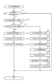
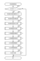
次に、図7を参照して、第1のパチンコ遊技機の遊技フローについて説明する。図7は、第1のパチンコ遊技機の遊技フローの一例である。なお、図7に示される遊技フローは、制御上のフローではなく、外観で把握できるフローである。
[1-3. Game flow]
Next, with reference to FIG. 7, the game flow of the first pachinko game machine will be explained. FIG. 7 is an example of a game flow of the first pachinko game machine. Note that the game flow shown in FIG. 7 is not a control flow, but a flow that can be understood from the appearance.
図7に示されるように、パチンコゲームでは、遊技者等のユーザー操作により遊技球が発射され、その遊技球が各種入賞口(例えば、第1始動口120等)に入賞した場合に遊技球の払出制御処理が行われる。パチンコゲームには、特別図柄を用いる特別図柄ゲームと、普通図柄を用いる普通図柄ゲームとが含まれる。特別図柄ゲームとは、例えば、始動口120,140A,140Bへの遊技球の入賞に基づいて特別図柄の当り判定処理を実行し、大当り遊技状態に移行させるか否か等を決定するゲームである。また、普通図柄ゲームとは、例えば、通過ゲート126への遊技球の通過に基づいて普通図柄の当り判定処理を実行し、普通電動役物146を作動させて入賞口(本実施例では第2始動口140B)を開放状態とするか否か等を決定するゲームである。なお、この明細書において、「特別図柄ゲーム」を「遊技」と称する場合もあるが、「遊技」は広い概念で用いられる用語であり、例えば、普通図柄ゲームや演出ボタン54等の操作部(例えば図1参照)を使用する演出上のゲーム等も「遊技」に含まれる。
As shown in FIG. 7, in a pachinko game, a game ball is fired by a user operation such as a player, and when the game ball enters various winning holes (for example, the
また、この明細書において、特別図柄の可変表示が開始されてから、この可変表示が終了して特別図柄の当り判定処理の結果が確定表示(導出)されるまで(より詳しくは、特別図柄確定時間が経過するまで)を1回の特別図柄ゲームとする。ただし、特別図柄の当り判定処理の結果が導出された後、大当り遊技状態や小当り遊技状態に制御された場合は、大当り遊技状態や小当り遊技状態の終了までを1回の特別図柄ゲームとする。 In addition, in this specification, from the start of the variable display of the special symbol until the end of the variable display and the final display (derivation) of the result of the special symbol hit determination process (more specifically, the special symbol is confirmed (until the time elapses) is regarded as one special symbol game. However, if the jackpot game state or small win game state is controlled after the result of the special symbol hit determination process is derived, the period up to the end of the jackpot game state or small win game state is considered to be one special symbol game. do.
特別図柄ゲームにおいて大当りを示す停止表示態様が第1特別図柄表示部163または第2特別図柄表示部164に導出されると、大当り遊技状態に制御される。大当り遊技状態では、特別電動役物133の作動によって大当り用大入賞口131が所定時間(例えば最大30000msec)にわたって開放状態となるラウンド遊技が実行され、大当り用大入賞口131への入賞可能性が相対的に高められる。
When the stop display mode indicating a jackpot in the special symbol game is led out to the first special
また、普通図柄ゲームにおいて普通図柄当りを示す停止表示態様が普通図柄表示部161に導出されると、普通電動役物146の作動によって入賞口(例えば、本実施例では第2始動口140B)が開放状態となり、例えば第2始動口140Bへの入賞可能性が相対的に高められる。
In addition, when the stop display mode indicating a normal symbol win in the normal symbol game is derived to the normal
なお、パチンコゲームにおいて実行可能なゲームは、特別図柄ゲームおよび普通図柄ゲームに限られず、これらとは別の新たなゲームを実行可能であってもよい。 Note that the games that can be executed in the pachinko game are not limited to the special symbol game and the normal symbol game, and a new game other than these may be executable.
以下、特別図柄ゲームおよび普通図柄ゲームの遊技フローの概要を説明する。 Hereinafter, an overview of the game flow of the special symbol game and the normal symbol game will be explained.
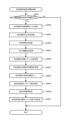
[1-3-1.特別図柄ゲーム]
図7に示されるように、特別図柄ゲームには、主として、第1始動口120または第2始動口140A,140Bへの入賞(通過)があった場合に行われる特別図柄始動入賞処理、および、特別図柄の始動条件が成立したことに基づいて行われる特別図柄制御処理、等が含まれる。
[1-3-1. Special design game]
As shown in FIG. 7, the special symbol game mainly includes a special symbol starting winning process that is performed when there is a winning (passage) to the
第1始動口120または第2始動口140A,140Bへの遊技球の入賞があった場合、特別図柄始動入賞処理が行われる。この特別図柄始動入賞処理では、特別図柄用の各種カウンタ(例えば、大当り判定用カウンタ、図柄決定用カウンタ等)から特別図柄にかかる各種データ(例えば、大当り判定用乱数値、図柄乱数値、リーチ判定用乱数値、および、演出選択用乱数値等の各種乱数値等)がそれぞれ抽出(取得)される。抽出された各乱数値は始動情報として保留される。この特別図柄始動入賞処理は、特別図柄制御処理の実行中であっても行われる。
When a game ball enters the
また、特別図柄制御処理では、特別図柄の始動条件が成立したか否かが判定される。特別図柄の始動条件が成立すると、特別図柄の大当り判定用カウンタから抽出された大当り判定用乱数値を参照し、「大当り」であるか否かを判定する特別図柄の当り判定処理が行われる。その後、停止図柄を決定する停止図柄決定処理が行われる。停止図柄決定処理では、特別図柄の図柄決定用カウンタから抽出された図柄決定用乱数値と、特別図柄の当り判定処理の結果とを参照し、停止表示させる特別図柄が決定される。 In addition, in the special symbol control process, it is determined whether or not the starting conditions for the special symbol are satisfied. When the special symbol starting condition is established, special symbol hit determination processing is performed to determine whether or not it is a "jackpot" by referring to the random number value for jackpot determination extracted from the special symbol jackpot determination counter. After that, a stop symbol determination process is performed to determine a stop symbol. In the stop symbol determination process, the special symbol to be stopped and displayed is determined by referring to the random number value for symbol determination extracted from the special symbol symbol determination counter and the result of the special symbol hit determination process.
なお、本実施例では、確変フラグがオンであれば確変制御が実行される。上記の特別図柄の当り判定処理では、確変フラグがオフの場合は相対的に低い確率で「大当り」であると判定され、確変フラグがオンの場合は相対的に高い確率で「大当り」であると判定される。以下、この明細書において、「大当り」であると判定される確率を「大当り確率」と称する。 In this embodiment, if the probability variation flag is on, probability variation control is executed. In the above special symbol hit determination process, if the variable probability flag is off, it is determined that it is a "jackpot" with a relatively low probability, and if the variable probability flag is on, it is determined that it is a "jackpot" with a relatively high probability. It is determined that Hereinafter, in this specification, the probability of being determined to be a "jackpot" will be referred to as "jackpot probability."
なお、確変フラグは、メインRAM203に格納される管理フラグの一つであり、確変制御を実行するか否かを管理するためのフラグである。確変フラグがオンの場合、確変制御が実行される遊技状態(例えば、本実施例では高確時短遊技状態や高確非時短遊技状態)において遊技が進行する。一方、確変フラグがオフの場合、確変制御が実行されない遊技状態(例えば、通常遊技状態や低確時短遊技状態)において遊技が進行する。
Note that the probability variation flag is one of the management flags stored in the
次いで、特別図柄の変動パターン決定処理が行われる。この処理では、変動パターン決定用カウンタから乱数値を抽出し、その乱数値と、上述した特別図柄の当り判定処理の結果と、上述した停止表示させる特別図柄とを参照し、特別図柄の変動パターン(可変表示パターン)が決定される。そして、特別図柄の変動パターン決定処理の結果に基づいて特別図柄の可変表示制御処理が行われる。 Next, a special symbol variation pattern determination process is performed. In this process, a random number value is extracted from the counter for determining the variation pattern, and the random number value, the result of the above-mentioned special symbol hit determination processing, and the above-mentioned special symbol to be stopped and displayed are referred to, and the variation pattern of the special symbol is (variable display pattern) is determined. Then, a special symbol variable display control process is performed based on the result of the special symbol variation pattern determination process.
特別図柄の変動パターンが決定されると、次に演出パターンを決定するための演出パターン決定処理が行われる。そして、演出パターン決定処理の結果に基づいて、表示装置7の表示領域に表示される例えば装飾図柄やキャラクタ演出等の表示演出、および、スピーカ32から出力される音声や効果音等の音演出等の演出制御処理が行われる。なお、演出制御処理はサブCPU301によって行われる。
Once the special symbol variation pattern is determined, a performance pattern determination process is then performed to determine the performance pattern. Based on the result of the performance pattern determination process, display effects such as decorative patterns and character effects are displayed in the display area of the
そして、特別図柄の可変表示制御処理および演出制御処理が終了し、大当りである場合、大当り遊技制御処理が行われる。大当り遊技制御処理は、大当り遊技状態において実行される処理である。大当り遊技状態が終了すると、特別図柄ゲームが終了し、大当りでない遊技状態への遊技状態移行制御処理が行われる。この場合、大当りの種類に応じて遊技状態が移行する。例えば、確変フラグおよび時短フラグのいずれもがオンにセットされる大当り種類である場合、大当り遊技状態の終了後、確変時短遊技状態に移行する。 Then, the special symbol variable display control process and performance control process are completed, and if it is a jackpot, a jackpot game control process is performed. The jackpot game control process is a process executed in the jackpot game state. When the jackpot gaming state ends, the special symbol game ends, and a gaming state transition control process to a non-jackpot gaming state is performed. In this case, the gaming state changes depending on the type of jackpot. For example, if the type of jackpot is such that both the variable probability flag and the time-saving flag are set to ON, after the jackpot gaming state ends, the state shifts to the variable probability-variable time-saving gaming state.
一方、大当りでないすなわちハズレである場合、特別図柄ゲームが終了する。なお、図7には示されていないが、小当りである場合、小当り遊技制御処理が行われる。 On the other hand, if it is not a jackpot, that is, if it is a loss, the special symbol game ends. Although not shown in FIG. 7, in the case of a small win, a small win game control process is performed.
そして、特別図柄の始動条件が成立する都度、上述した特別図柄制御処理の各種処理が繰り返される。 Then, each time the special symbol starting condition is satisfied, various processes of the special symbol control process described above are repeated.
なお、特別図柄制御処理中に始動口120,140A,140Bへの遊技球の入賞があった場合、特別図柄始動入賞処理が実行される。また、始動口120,140A,140Bへの遊技球の入賞時に抽出される特別図柄の始動情報(例えば、大当り判定用乱数値、特別図柄の図柄乱数値、リーチ判定用乱数値、および、演出選択用乱数値等の各種乱数値等の各種データ)を、特別図柄の始動条件が成立するまで保留する。
In addition, when there is a winning of a game ball to the
また、第1のパチンコ遊技機では、第1特別図柄の始動情報の4個と第2特別図柄の始動情報の4個とで合計最大8個まで特別図柄の始動情報を保留することができるが、保留できる特別図柄の始動情報の数はこれに限られない。例えば、第1特別図柄の始動情報を第2特別図柄の始動情報よりも多く保留できるようにしてもよいし、第2特別図柄の始動情報を第1特別図柄の始動情報よりも多く保留できるようにしてもよい。 In addition, in the first pachinko gaming machine, it is possible to hold up to a total of eight pieces of special symbol starting information, including four pieces of starting information of the first special symbol and four pieces of starting information of the second special symbol. , The number of starting information of special symbols that can be held is not limited to this. For example, it may be possible to hold more starting information for the first special symbol than for the second special symbol, or it may be possible to hold more starting information for the second special symbol than for the first special symbol. You can also do this.
また、図7には示されていないが、特別図柄が始動入賞してから特別図柄の始動条件が成立するまでの間に、始動口120,140A,140Bへの遊技球の入賞(通過)時に抽出された始動情報に基づいて当落(「大当り」当選の有無)や変動パターンを特別図柄の当り判定処理に先だって判定する先読み判定を行い、この先読み判定の結果に基づいて所定の演出を行う先読み演出機能を備えるようにしてもよい。なお、上記の先読み判定は、始動口120,140A,140Bへの遊技球の入賞によって抽出された始動情報が保留される前に行ってもよいし、保留された後に行ってもよい。
Although not shown in FIG. 7, when a game ball enters (passes) the
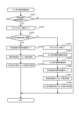
[1-3-2.普通図柄ゲーム]
図7に示されるように、普通図柄ゲームには、主として、通過ゲート126への遊技球の通過があった場合に行われる普通図柄始動通過処理、および、普通図柄の始動条件が成立したことに基づいて行われる普通図柄制御処理、等が含まれる。
[1-3-2. Normal symbol game]
As shown in FIG. 7, the normal symbol game mainly includes a normal symbol start passing process that is performed when a game ball passes through the
通過ゲート126への遊技球の通過があった場合、普通図柄始動通過処理が実行される。この普通図柄始動通過処理では、普通図柄用の当り判定用カウンタから普通図柄の始動情報(例えば、普通図柄の当り判定用乱数値等)を抽出(取得)し、抽出した始動情報を保留する。
When a game ball passes through the
また、普通図柄制御処理では、メインCPU201は、普通図柄の始動条件が成立したか否かを判定する。普通図柄の可変表示を開始する場合、メインCPU201は、普通図柄用の当り判定用カウンタから抽出された普通図柄の当り判定用乱数値を参照し、「普通図柄当り」とするか否かの普通図柄の当り判定処理を実行し、その後、変動パターン決定処理を実行する。この処理では、普通図柄の当り判定処理の結果が参照され、普通図柄の変動パターンが決定される。
In addition, in the normal symbol control process, the
次いで、メインCPU201は、普通図柄当り判定処理の結果、および、決定された普通図柄の変動パターンを参照し、普通図柄の可変表示の制御を行う可変表示制御処理、および、所定の演出を行う演出制御処理を実行する。なお、演出制御処理は実行されない場合もある。
Next, the
そして、普通図柄の可変表示制御処理および演出制御処理が終了すると、メインCPU201は、「普通図柄当り」を示す普通当り図柄が普通図柄表示部161(図6参照)に導出されたか否かを判定する。普通当りを示す停止表示態様が導出されたと判定すると、メインCPU201は、普通図柄当り遊技制御処理を実行する。この普通図柄当り遊技制御処理では、普通電動役物146(図4、図6参照)が作動し、入賞口(例えば、本実施例では例えば第2始動口140B(図4参照))への遊技球の入賞(通過)が可能または容易な開放状態となる。一方、普通当りを示す停止表示態様が導出されなかったと判定すると、メインCPU201は、普通図柄当り遊技制御処理を実行せず、普通図柄制御処理を終了する。
Then, when the normal symbol variable display control processing and production control processing are completed, the
なお、時短制御が実行されない遊技状態(例えば、通常遊技状態)では、普通当りを示す停止表示態様が導出される確率を0にしてもよい。時短制御は、時短制御が実行されていないときと比べて、特別図柄の可変表示時間を短縮させる特図短縮制御、および、普通電動役物146を作動させて入賞口(本実施例では例えば第2始動口140B)を開放状態とする頻度を高める電サポ制御、のうち少なくともいずれか一方が行われる制御が相当する。この時短制御は、特図短縮制御および電サポ制御の両方を行う制御としてもよいし、特図短縮制御および電サポ制御のうちいずれか一方のみを行う制御としてもよい。
In addition, in a gaming state in which time saving control is not executed (for example, a normal gaming state), the probability that a stop display mode indicating a normal win is derived may be set to 0. The time saving control includes a special symbol shortening control that shortens the variable display time of the special symbol compared to when the time saving control is not executed, and a special symbol shortening control that shortens the variable display time of the special symbol, and a winning opening (in this embodiment, for example, This corresponds to control that performs at least one of the electric support control that increases the frequency of opening the
そして、普通図柄の始動条件が成立する都度、上述した普通図柄制御処理の各種処理が繰り返される。 Then, each time the starting condition for the normal symbol is satisfied, the various processes of the normal symbol control process described above are repeated.
なお、普通図柄制御処理中に通過ゲート126への遊技球の通過があった場合、普通図柄始動通過処理が実行される。また、通過ゲート126への遊技球の通過時に抽出される普通図柄の始動情報(例えば、普通図柄の当り判定用乱数値等)を、普通図柄の始動条件が成立するまで保留する。
In addition, when a game ball passes through the
なお、普通図柄の可変表示の開始は保留された順に行われ、普通図柄の始動条件が成立すると、保留されている普通図柄の始動情報のうち最先で保留された始動情報についての可変表示を実行する。 In addition, the start of the variable display of the normal symbols is performed in the order in which they are put on hold, and when the starting conditions for the normal symbols are met, the variable display of the starting information that was held first among the starting information of the normal symbols that are on hold will be started. Execute.
なお、各種乱数値(例えば、第1特別図柄の大当り判定用乱数値、第1特別図柄の図柄乱数値、第1特別図柄のリーチ判定用乱数値、第2特別図柄の大当り判定用乱数値、第2特別図柄の図柄乱数値、第2特別図柄のリーチ判定用乱数値、および、普通図柄の当り判定用乱数値等)の抽出方式は、メインCPU201によりプログラムを実行することによって所定の範囲(幅)内で乱数値を生成するソフト乱数方式を用いてもよいし、所定周期で乱数が更新される乱数発生器におけるカウンタから乱数値を抽出するハード乱数方式を用いてもよい。
In addition, various random numbers (for example, random numbers for jackpot determination of the first special symbol, random numbers for the first special symbol, random values for reach determination of the first special symbol, random values for jackpot determination of the second special symbol, The extraction method of the second special symbol random number, the second special symbol random number for reach determination, the normal symbol random number for hit determination, etc.) is performed by executing a program by the
[1-4.基本仕様]
次に、図8~図12を参照して、第1のパチンコ遊技機の基本仕様について説明する。
[1-4. basic specifications]
Next, the basic specifications of the first pachinko gaming machine will be explained with reference to FIGS. 8 to 12.
なお、第1のパチンコ遊技機では、確変制御および時短制御のいずれも実行されない通常遊技状態、確変制御および時短制御の両方が実行される高確時短遊技状態、確変制御は実行されるものの時短制御が実行されない高確非時短遊技状態、並びに、確変制御は実行されないものの時短制御が実行される低確時短遊技状態が用意されており、メインCPU201は、これらの遊技状態のうちいずれかの遊技状態において遊技を進行させることが可能となっている。ただし、メインCPU201の制御によって進行される遊技状態はこれに限られず、通常遊技状態、高確時短遊技状態、高確非時短遊技状態および低確時短遊技状態のうちいずれかの遊技状態については進行されないようにしてもよい。例えば、通常遊技状態、高確時短遊技状態および低確時短遊技状態のうちいずれかの遊技状態において遊技が進行するようにし、高確非時短遊技状態において遊技が進行しないようにする等してもよい。
In addition, in the first pachinko gaming machine, there is a normal gaming state in which neither probability variable control nor time saving control is executed, a high precision time saving gaming state in which both probability variable control and time saving control are executed, and a time saving control in which probability variable control is executed. There are a high probability non-time saving gaming state in which the game is not executed, and a low probability time saving gaming state in which the probability changing control is not executed but the time saving control is executed, and the
本実施例において、通常遊技状態では左打ちが推奨され、高確時短遊技状態、高確非時短遊技状態および低確時短遊技状態では右打ちが推奨される。サブCPU301は、推奨される打ち方を、例えば表示装置7の表示領域に表示する制御を実行する。
In this embodiment, left-handed playing is recommended in the normal gaming state, and right-handed playing is recommended in the high-accuracy time-saving gaming state, the high-accuracy non-time-saving gaming state, and the low-accuracy time-saving gaming state. The
[1-4-1.設定値毎の大当り確率]
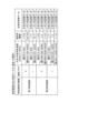
図8は、第1のパチンコ遊技機における設定値毎の大当り確率(概算)を示すテーブルの一例である。図8に示されるように、第1のパチンコ遊技機では、上述の設定キー174やバックアップクリアスイッチ176(いずれも図6参照)等を用いて、例えば設定1~設定6といった複数の設定値のうちいずれか一の設定値にセットすることができる。このような設定機能付きパチンコ遊技機の場合、大当り確率は設定値に応じて異なっており、メインCPU201は、セットされた設定値に基づいて特別図柄の当り判定処理を実行する。
[1-4-1. Jackpot probability for each setting value]
FIG. 8 is an example of a table showing the jackpot probability (approximately) for each set value in the first pachinko gaming machine. As shown in FIG. 8, in the first pachinko game machine, a plurality of setting values, such as
具体的には、確変制御が実行されない確変フラグがオフの遊技状態(本実施例では例えば通常遊技状態および低確時短遊技状態)における大当り確率は、第1特別図柄の当り判定処理および第2特別図柄の当り判定処理のいずれが実行された場合であっても、例えば、設定1で約319分の1、設定2で約314分の1、設定3で約309分の1、設定4で約304分の1、設定5で約299分の1、設定6で約294分の1となっている。また、確変制御が実行される確変フラグがオンの遊技状態(本実施例では例えば高確時短遊技状態および高確非時短遊技状態)における大当り確率は、設定1で約77分の1、設定2で約76分の1、設定3で約75分の1、設定4で約74分の1、設定5で約73分の1、設定6で約72分の1となっている。なお、小当り確率については図8に示されていないが、設定値に応じて異なるようにしてもよいし、設定1~設定6で共通の確率としてもよい。
Specifically, the jackpot probability in a gaming state where the probability variation flag is off (in this example, the normal gaming state and the low probability time-saving gaming state) in which probability variation control is not executed is determined by the first special symbol hit determination process and the second special Regardless of which symbol hit determination process is executed, for example, setting 1 is approximately 1/319, setting 2 is approximately 1/314, setting 3 is approximately 1/309, and setting 4 is approximately 1/319. The value is 1/304, approximately 1/299 with setting 5, and approximately 1/294 with setting 6. In addition, the jackpot probability in the gaming state where the probability change flag is on (in this example, the high probability time-saving gaming state and the high probability non-time saving gaming state) in which probability variation control is executed is approximately 1/77 at setting 1, and about 1/77 at setting 2. setting is approximately 1/76, setting 3 is approximately 1/75, setting 4 is approximately 1/74, setting 5 is approximately 1/73, and setting 6 is approximately 1/72. Although the small hit probability is not shown in FIG. 8, it may be different depending on the setting value, or may be a common probability for
また、本実施例では、全ての設定値においてそれぞれ大当り確率が異なっているが、これに限定されず、例えば、設定1と設定2とで共通の大当り確率、設定3と設定4とで共通の大当り確率、設定5と設定6とで共通の大当り確率といったように、複数の設定値で大当り確率を同じにしてもよい。
In addition, in this embodiment, the jackpot probabilities are different for all setting values, but the invention is not limited to this. For example, the jackpot probability is common between setting 1 and setting 2, and the jackpot probability is common between setting 3 and setting 4. The jackpot probability may be the same for a plurality of setting values, such as a jackpot probability or a common jackpot probability between
また、本実施例では、設定値に応じて大当り確率が異なっているが、遊技者にとっての有利度合いが設定値に応じて異なれば、設定値に応じて異なる対象が必ずしも大当り確率に限定されない。例えば、特定の入賞口に遊技球が入賞すると大当り遊技状態に制御されるようなパチンコ遊技機であれば、設定値に応じて特定の入賞口への入賞確率を異ならせるようにしてもよい。なお、パチンコ遊技機を、設定機能付きパチンコ遊技機とすることは必須ではない。 Further, in this embodiment, the jackpot probability varies depending on the set value, but if the degree of advantage for the player varies depending on the set value, the target that differs depending on the set value is not necessarily limited to the jackpot probability. For example, in the case of a pachinko game machine that is controlled to a jackpot gaming state when a game ball enters a specific winning opening, the probability of winning a prize in a specific winning opening may be varied depending on a set value. Note that it is not essential that the pachinko game machine be a pachinko game machine with a setting function.
[1-4-2.特別図柄の当り判定テーブル]
図9は、第1のパチンコ遊技機が備える主制御回路200のメインROM202に記憶されている特別図柄の当り判定テーブルの一例である。なお、図9に示される特別図柄の当り判定テーブルは、図8に示される設定1の場合を一例として示したものである。
[1-4-2. Special symbol hit determination table]
FIG. 9 is an example of a special symbol hit determination table stored in the
特別図柄の当り判定テーブルは、特別図柄の当り判定処理において参照されるテーブル、すなわち、第1始動口120または第2始動口140A,140Bに遊技球が入賞した際に取得される大当り判定用乱数値に基づいて「大当り」、「小当り」または「ハズレ」を抽選により決定する際に参照されるテーブルである。なお、本実施例では、第1特別図柄の当り判定処理における抽選対象は「大当り」および「ハズレ」のみである。これに対し、第2特別図柄の当り判定処理における抽選対象は「大当り」、「小当り」および「ハズレ」である。ただし、第1特別図柄の当り判定処理における抽選対象に「小当り」を含めるようにしてもよい。
The special symbol hit determination table is a table that is referred to in the special symbol hit determination process, that is, a jackpot determination table that is obtained when a game ball enters the
大当り判定用乱数値は、上述したとおり、特別図柄の当り判定処理に用いられる乱数値である。本実施例において、大当り判定用乱数値は、0~65535(65536種類)の中から抽出される。ただし、発生する乱数値の範囲は上記に限られない。 The random number value for jackpot determination is a random number value used for the special symbol hit determination process, as described above. In this embodiment, the random number value for jackpot determination is extracted from 0 to 65535 (65536 types). However, the range of generated random numbers is not limited to the above.
本実施例では、第1特別図柄の当り判定処理において、抽出された大当り判定用乱数値に基づいて「大当り」または「ハズレ」に決定される。第1特別図柄の当り判定テーブルには、確変フラグの値(0または1)毎に、「大当り」に決定される大当り判定用乱数値の範囲(幅)とこれに対応する大当り判定値データとの関係、および、「ハズレ」に決定される大当り判定用乱数値の範囲(幅)とこれに対応するハズレ判定値データとの関係が規定されている。 In this embodiment, in the hit determination process for the first special symbol, a "jackpot" or "loss" is determined based on the extracted random number value for jackpot determination. The hit determination table of the first special symbol includes the range (width) of the random number value for jackpot determination determined as a "jackpot" and the corresponding jackpot determination value data for each value of the probability change flag (0 or 1). The relationship between the range (width) of the random number value for jackpot determination that is determined to be a "loss" and the corresponding loss determination value data is defined.
なお、本明細書において、確変フラグの値が「0」の場合、確変フラグがオフであり、確変フラグの値が「1」の場合、確変フラグがオンである。 In this specification, when the value of the probability variation flag is "0", the probability variation flag is off, and when the value of the probability variation flag is "1", the probability variation flag is on.
また、第2特別図柄の当り判定処理において、抽出された大当り判定用乱数値に基づいて「大当り」、「小当り」または「ハズレ」に決定される。第2特別図柄の当り判定テーブルには、確変フラグの値(0または1)毎に、「大当り」に決定される大当り判定用乱数値の範囲(幅)とこれに対応する大当り判定値データとの関係、「小当り」に決定される大当り判定用乱数値の範囲(幅)とこれに対応する小当り判定値データとの関係、および、「ハズレ」に決定される大当り判定用乱数値の範囲(幅)とこれに対応するハズレ判定値データとの関係が規定される。 In addition, in the second special symbol hit determination process, a "big hit", "small hit", or "loss" is determined based on the extracted random number value for jackpot determination. The hit determination table of the second special symbol includes the range (width) of the random number value for jackpot determination determined as a "jackpot" and the corresponding jackpot determination value data for each value (0 or 1) of the probability change flag. , the relationship between the range (width) of the random number value for jackpot determination that is determined as a "small hit" and the corresponding small hit determination value data, and the relationship between the random number value for jackpot determination that is determined as a "loss" The relationship between the range (width) and the corresponding loss determination value data is defined.
本実施例では、第1特別図柄の当り判定処理時に確変フラグがオフであって、抽出された大当り判定用乱数値が0~204のいずれかである場合は「大当り」と判定され、当落判定値データは「大当り判定値データ」に決定される。また、第1特別図柄の当り判定処理時に確変フラグがオフであって、抽出された大当り判定用乱数値が0~204のいずれでもない場合は「ハズレ」と判定され、判定値データは「ハズレ判定値データ」に決定される。 In this embodiment, if the variable probability flag is off during the hit determination process for the first special symbol and the extracted random number for determining a jackpot is between 0 and 204, it is determined as a "jackpot" and the winning/losing determination is made. The value data is determined to be "jackpot determination value data." Also, if the probability change flag is off during the hit determination process for the first special symbol and the extracted random number value for jackpot determination is not between 0 and 204, it will be determined as a "loss", and the determination value data will be "lost". "Judgement value data" is determined.
また、第1特別図柄の当り判定処理時に確変フラグがオンであって、抽出された大当り判定用乱数値が0~850のいずれかである場合は「大当り」と判定され、判定値データは「大当り判定値データ」に決定される。また、第1特別図柄の当り判定処理時に確変フラグがオンであって、抽出された大当り判定用乱数値が0~850のいずれでもない場合、「ハズレ」と判定され、判定値データは「ハズレ判定値データ」に決定される。 Also, if the probability change flag is on during the hit determination process of the first special symbol and the extracted random number value for jackpot determination is between 0 and 850, it is determined as a "jackpot", and the determination value data is " Jackpot judgment value data” is determined. Also, if the probability change flag is on during the hit determination process of the first special symbol and the extracted random number value for jackpot determination is not between 0 and 850, it will be determined as a "lose", and the determination value data will be set as "lose". "Judgement value data" is determined.
同様に、第2特別図柄の当り判定処理時に確変フラグがオフであって、抽出された大当り判定用乱数値が0~204のいずれかである場合は「大当り」と判定され、判定値データは「大当り判定値データ」に決定される。また、第2特別図柄の当り判定処理時に確変フラグがオフであって、抽出された大当り判定用乱数値が205~22049のいずれかである場合は「小当り」と判定され、判定値データは「小当り判定値データ」に決定される。さらに、第2特別図柄の当り判定処理時に確変フラグがオフであって、抽出された大当り判定用乱数値が0~22049のいずれでもない場合は「ハズレ」と判定され、判定値データは「ハズレ判定値データ」に決定される。 Similarly, when the probability change flag is off during the hit determination process for the second special symbol, and the extracted random number value for jackpot determination is between 0 and 204, it is determined as a "jackpot", and the determination value data is It is determined as "Jackpot Judgment Value Data". In addition, if the probability change flag is off during the hit determination process of the second special symbol and the extracted random number value for jackpot determination is one of 205 to 22049, it will be determined as a "small hit", and the determination value data will be It is determined as "small hit judgment value data". Furthermore, if the probability change flag is off during the hit determination process for the second special symbol and the extracted random number value for jackpot determination is not between 0 and 22049, it will be determined as a "loss", and the determination value data will be "lost". "Judgement value data" is determined.
また、第2特別図柄の当り判定処理時に確変フラグがオンであって、抽出された大当り判定用乱数値が0~850のいずれかである場合は「大当り」と判定され、判定値データは「大当り判定値データ」に決定される。また、第2特別図柄の当り判定処理時に確変フラグがオンであって、抽出された大当り判定用乱数値が851~22695のいずれかである場合は「小当り」と判定され、判定値データは「小当り判定値データ」に決定される。さらに、第2特別図柄の当り判定処理時に確変フラグがオンであって、抽出された大当り判定用乱数値が0~22695のいずれでもない場合は「ハズレ」と判定され、判定値データは「ハズレ判定値データ」に決定される。 In addition, if the probability change flag is on during the hit determination process of the second special symbol and the extracted random number value for jackpot determination is between 0 and 850, it is determined as a "jackpot", and the determination value data is " Jackpot judgment value data” is determined. In addition, if the probability change flag is on during the hit determination process of the second special symbol and the extracted random number value for jackpot determination is one of 851 to 22695, it will be determined as a "small hit", and the determination value data will be It is determined as "small hit judgment value data". Furthermore, if the probability change flag is on during the hit determination process of the second special symbol and the extracted random number value for jackpot determination is not between 0 and 22695, it will be determined as a "loss", and the determination value data will be "lost". "Judgement value data" is determined.
[1-4-3.特別図柄判定テーブル]
図10は、第1のパチンコ遊技機が備える主制御回路200のメインROM202に記憶されている特別図柄判定テーブルの一例である。
[1-4-3. Special symbol judgment table]
FIG. 10 is an example of a special symbol determination table stored in the
特別図柄判定テーブルは、第1始動口120または第2始動口140A、140Bに遊技球が入賞した際に取得される特別図柄の図柄乱数値と先述の当落判定値データとに基づいて、停止図柄を決定付ける「当り時選択図柄コマンド」および「図柄指定コマンド」を選択する際に参照されるテーブルである。「当り時選択図柄コマンド」は、特別図柄の当り判定処理の結果が大当りであった場合に、大当り種類に応じて定められる当り図柄を指定するためのコマンドであり、「図柄指定コマンド」は、特別図柄の可変表示の停止時に表示される図柄を指定するためのコマンドである。特別図柄の図柄乱数値は、例えば0~99(100種類)の中から抽出される。
The special symbol determination table determines the stop symbol based on the symbol random value of the special symbol obtained when a game ball enters the
図10に示される特別図柄判定テーブルによれば、第1特別図柄の当り判定処理の結果として大当り判定値データが得られた場合、例えば、当り時選択図柄コマンドおよび図柄指定コマンドは以下のように選択される。すなわち、第1特別図柄の図柄乱数値が0または1である場合、当り時選択図柄コマンドとして「z0」が選択され、図柄指定コマンドとして「zA1」が選択される。また、第1特別図柄の図柄乱数値が2~9のいずれかである場合、当り時選択図柄コマンドとして「z1」が選択され、図柄指定コマンドとして「zA1」が選択される。また、第1特別図柄の図柄乱数値が10~59のいずれかである場合、当り時選択図柄コマンドとして「z2」が選択され、図柄指定コマンドとして「zA2」が選択される。さらに、第1特別図柄の図柄乱数値が60~99のいずれかである場合、当り時選択図柄コマンドとして「z3」が選択され、図柄指定コマンドとして「zA2」が選択される。 According to the special symbol determination table shown in FIG. 10, when jackpot determination value data is obtained as a result of the hit determination process for the first special symbol, for example, the hit selection symbol command and symbol designation command are as follows. selected. That is, when the symbol random value of the first special symbol is 0 or 1, "z0" is selected as the winning symbol command and "zA1" is selected as the symbol designation command. Further, when the symbol random number value of the first special symbol is one of 2 to 9, "z1" is selected as the winning symbol command and "zA1" is selected as the symbol designation command. Furthermore, when the symbol random number value of the first special symbol is one of 10 to 59, "z2" is selected as the winning symbol command and "zA2" is selected as the symbol designation command. Further, when the symbol random number value of the first special symbol is one of 60 to 99, "z3" is selected as the winning symbol command and "zA2" is selected as the symbol designation command.
また、第1特別図柄の当り判定処理の結果としてハズレ判定値データが得られた場合、第1特別図柄の図柄乱数値が0~99のいずれであっても、当り時選択図柄コマンドは選択されず、図柄指定コマンドは「zA3」が選択される。 In addition, if loss judgment value data is obtained as a result of the hit judgment process for the first special symbol, the hit selection symbol command will not be selected regardless of the symbol random number value of the first special symbol from 0 to 99. First, "zA3" is selected as the symbol designation command.
また、第2特別図柄の当り判定処理の結果として大当り判定値データが得られた場合、例えば、当り時選択図柄コマンドおよび図柄指定コマンドは以下のように選択される。すなわち、第2特別図柄の図柄乱数値が0~29のいずれかである場合、当り時選択図柄コマンドとして「z4」が選択され、図柄指定コマンドとして「zA4」が選択される。また、第2特別図柄の図柄乱数値が30~59のいずれかである場合、当り時選択図柄コマンドとして「z5」が選択され、図柄指定コマンドとして「zA5」が選択される。さらに、第2特別図柄の図柄乱数値が60~99のいずれかである場合、当り時選択図柄コマンドとして「z6」が選択され、図柄指定コマンドとして「zA5」が選択される。 Further, when jackpot determination value data is obtained as a result of the second special symbol hit determination process, for example, the hit selection symbol command and symbol designation command are selected as follows. That is, when the symbol random number value of the second special symbol is one of 0 to 29, "z4" is selected as the winning symbol command and "zA4" is selected as the symbol designation command. Further, when the symbol random number value of the second special symbol is one of 30 to 59, "z5" is selected as the winning symbol command and "zA5" is selected as the symbol designation command. Furthermore, if the symbol random number value of the second special symbol is one of 60 to 99, "z6" is selected as the winning symbol command and "zA5" is selected as the symbol designation command.
また、第2特別図柄の当り判定処理の結果として小当り判定値データが得られた場合、特別図柄の図柄乱数値が0~99のいずれであっても、当り時選択図柄コマンドとして「z7」が選択され、図柄指定コマンドとして「zA6」が選択される。 Also, if small hit judgment value data is obtained as a result of the second special symbol's hit judgment process, "z7" is used as the hit selection symbol command regardless of the symbol random number value of the special symbol from 0 to 99. is selected, and "zA6" is selected as the symbol designation command.
なお、第2特別図柄の当り判定処理の結果として小当り判定値データが得られると、メインCPU201は、小当り遊技制御処理を実行する。小当り遊技制御処理では、例えば小当り用シャッタ153(図6参照)を作動させて、小当り用大入賞口151(図4参照)への遊技球の入賞(通過)が可能または容易な開放状態となる制御を実行し、賞球が払い出され得る。
In addition, when the small hit determination value data is obtained as a result of the second special symbol hit determination process, the
また、第2特別図柄の当り判定処理の結果が「ハズレ」であった場合、特別図柄の図柄乱数値が0~99のいずれであっても、当り時選択図柄コマンドは選択されず、図柄指定コマンドは「zA7」が選択される。 In addition, if the result of the second special symbol's hit determination process is "lose", the hit selection symbol command will not be selected, and the symbol designation command will not be selected, regardless of the symbol random number value of the special symbol from 0 to 99. The command "zA7" is selected.
なお、本実施例では、特別図柄の当り判定テーブル(図9参照)を参照して、抽出された大当り判定用乱数値に基づいて当落判定値データを決定し、その後、特別図柄判定テーブル(図10参照)を参照して、特別図柄の図柄乱数値に基づいて当り時選択図柄コマンドおよび図柄指定コマンドを決定するといった所謂2段階抽選を行うようにしているが、これに限られない。例えば、抽出された大当り判定用乱数値と特別図柄の図柄乱数値とに基づいて、特別図柄の当落、当り時選択図柄コマンドおよび図柄指定コマンドを決定するといった所謂1段階抽選を行うようにしてもよい。 In addition, in this embodiment, the win/loss judgment value data is determined based on the extracted random value for jackpot judgment with reference to the special symbol hit judgment table (see Figure 9), and then the special symbol judgment table (see Figure 9) is determined. 10), a so-called two-stage lottery is performed in which a winning selection symbol command and a symbol designation command are determined based on the symbol random number value of the special symbol, but the present invention is not limited to this. For example, a so-called one-stage lottery may be performed in which the winning of the special symbol, the selection symbol command at the time of winning, and the symbol designation command are determined based on the extracted random value for jackpot determination and the symbol random value of the special symbol. good.
[1-4-4.大当り種類決定テーブル]
図11は、第1のパチンコ遊技機が備える主制御回路200のメインROM202に記憶されている大当り種類決定テーブルの一例である。大当り種類決定テーブルは、特別図柄の図柄乱数値に対応して決定される当り時選択図柄コマンドに応じて、大当り遊技状態において実行されるラウンド数、確変フラグの値、確変回数、時短フラグの値、および、時短回数等、大当りの種類を決定する際に参照される。
[1-4-4. Jackpot type determination table]
FIG. 11 is an example of a jackpot type determination table stored in the
なお、本明細書において、確変フラグの場合と同様に、時短フラグの値が「0」の場合が時短フラグオフであり、時短フラグの値が「1」の場合が時短フラグオンである。 In addition, in this specification, similarly to the case of the variable probability flag, when the value of the time saving flag is "0", the time saving flag is off, and when the value of the time saving flag is "1", the time saving flag is on.
本実施例では、第1特別図柄の当り判定処理の結果が「大当り」であった場合、大当り種類は次のとおり決定される。例えば、当り時選択図柄コマンドが「z0」の場合、ラウンド数が「10」、確変フラグがオン、確変回数が「10000」、時短フラグがオフに決定される。また、当り時選択図柄コマンドが「z1」の場合、ラウンド数が「10」、確変フラグがオン、確変回数が「10000」、時短フラグがオン、時短回数が「10000」に決定される。また、当り時選択図柄コマンドが「z2」の場合、ラウンド数が「4」、確変フラグがオン、確変回数が「10000」、時短フラグがオン、時短回数が「10000」に決定される。さらに、当り時選択図柄コマンドが「z3」の場合、ラウンド数が「4」、確変フラグがオフ、時短フラグがオン、時短回数が「50」に決定される。 In this embodiment, when the result of the hit determination process for the first special symbol is a "jackpot", the jackpot type is determined as follows. For example, when the winning selection symbol command is "z0", the number of rounds is determined to be "10", the probability change flag is on, the number of probability changes is "10000", and the time saving flag is set to off. Further, when the winning selection symbol command is "z1", the number of rounds is determined to be "10", the probability variation flag is on, the probability variation number is "10000", the time saving flag is on, and the time saving number is determined to be "10000". Further, when the winning selection symbol command is "z2", the number of rounds is determined to be "4", the probability variation flag is on, the probability variation number is "10000", the time saving flag is on, and the time saving number is determined to be "10000". Furthermore, when the winning selection symbol command is "z3", the number of rounds is determined to be "4", the probability change flag is off, the time saving flag is on, and the number of time saving times is determined to be "50".
また、第2特別図柄の当り判定処理の結果が「大当り」であった場合、大当り種類は次のとおり決定される。例えば、当り時選択図柄コマンドが「z4」の場合、ラウンド数が「10」、確変フラグがオン、確変回数が「10000」、時短フラグがオフに決定される。また、当り時選択図柄コマンドが「z5」の場合、ラウンド数が「10」、確変フラグがオン、確変回数が「10000」、時短フラグがオン、時短回数が「10000」に決定される。さらに、当り時選択図柄コマンドが「z6」の場合、ラウンド数が「10」、確変フラグがオフ、時短フラグがオン、時短回数が「50」に決定される。 Further, when the result of the hit determination process for the second special symbol is a "jackpot", the jackpot type is determined as follows. For example, when the winning selection symbol command is "z4", the number of rounds is determined to be "10", the probability change flag is on, the number of probability changes is "10000", and the time saving flag is set to off. Further, when the winning selection symbol command is "z5", the number of rounds is determined to be "10", the probability variation flag is on, the probability variation number is "10000", the time saving flag is on, and the time saving number is determined to be "10000". Furthermore, when the winning selection symbol command is "z6", the number of rounds is determined to be "10", the probability change flag is off, the time saving flag is on, and the number of time saving times is determined to be "50".
ただし、図11に示される大当りの種類は一例であって、これに限られない。なお、確変フラグの値が「0」に決定される場合、確変回数は決定されないが、確変制御が実行されないという意味で確変回数が「0」にセットされるようにしてもよい。 However, the types of jackpots shown in FIG. 11 are merely examples, and are not limited thereto. Note that when the value of the probability variation flag is determined to be "0", the number of probability variations is not determined, but the probability variation number may be set to "0" to mean that probability variation control is not executed.
なお、確変回数の「10000」は、大当り遊技状態終了後の遊技状態において実行される特別図柄の当り判定処理において大当りであると判定される(すなわち次回大当り)まで、確変制御を継続して実行できる趣旨である。 In addition, the probability variation number of "10000" means that probability variation control is continuously executed until it is determined to be a jackpot in the special symbol hit determination process executed in the gaming state after the end of the jackpot gaming state (i.e., the next jackpot). The idea is that it can be done.
[1-4-5.特別図柄の変動パターンテーブル]
図12は、第1のパチンコ遊技機の特別図柄の変動パターンテーブルの一例であって、(A)低スタート用の特別図柄の変動パターンテーブル、(B)高スタート用の特別図柄の変動パターンテーブルである。なお、図12中の「演出内容」の欄は、分かりやすいように便宜上示したものである。メインCPU201は、第1始動口120への遊技球の入賞に基づくときは第1特別図柄の変動パターンを決定し、第2始動口140A,140Bへの遊技球の入賞に基づくときは第2特別図柄の変動パターンを決定する。
[1-4-5. Special symbol variation pattern table]
FIG. 12 is an example of a special symbol variation pattern table of the first pachinko gaming machine, including (A) a special symbol variation pattern table for a low start, and (B) a special symbol variation pattern table for a high start. It is. Note that the "performance content" column in FIG. 12 is shown for convenience to make it easier to understand. The
左打ちが推奨される通常遊技状態では、例えば図12(A)に示される低スタート用の特別図柄の変動パターンテーブルを参照して特別図柄の変動パターンが決定される。 In the normal game state where left-handed hitting is recommended, the special symbol variation pattern is determined by referring to the special symbol variation pattern table for low start shown in FIG. 12(A), for example.
一方、右打ちが推奨される遊技状態、すなわち、高確時短遊技状態、高確非時短遊技状態または低確時短遊技状態では、例えば図12(B)に示される高スタート用の特別図柄の変動パターンテーブルを参照して特別図柄の変動パターンが決定される。 On the other hand, in a gaming state in which right-handed hitting is recommended, that is, a high-accuracy time-saving gaming state, a high-accuracy non-time-saving gaming state, or a low-accuracy time-saving gaming state, for example, the variation of special symbols for a high start shown in FIG. 12(B) A special symbol variation pattern is determined with reference to the pattern table.
図12(A)および(B)に示されるように、特別図柄の変動パターンは、特別図柄の種別、特別図柄の当り判定処理の結果(当落)、リーチ判定用乱数値、および、演出選択用乱数値に基づいて決定される。ただし、これに限られず、上記のいずれかに代えてまたは加えて他の値等に基づいて決定されるようにしてもよい。 As shown in FIGS. 12(A) and (B), the variation pattern of the special symbol includes the type of the special symbol, the result of the special symbol's hit determination process (win or loss), the random number for reach determination, and the random number for effect selection. Determined based on random values. However, the present invention is not limited to this, and may be determined based on other values in place of or in addition to any of the above.
なお、リーチ判定用乱数値は例えば0~249(250種類)の中から抽出され、演出選択用乱数値は例えば0~99(100種類)の中から抽出される。ただし、発生する乱数値の範囲は上記に限られない。 Note that the random number value for reach determination is extracted from, for example, 0 to 249 (250 types), and the random number value for performance selection is extracted from, for example, 0 to 99 (100 types). However, the range of generated random numbers is not limited to the above.
高スタート用の特別図柄の変動パターンテーブルを参照して特別図柄の変動パターンを決定した場合、低スタート用の特別図柄の変動パターンテーブルを参照して特別図柄の変動パターンを決定した場合と比べて、単位時間あたりの特別図柄の可変表示回数の期待値が大きい。とくに、低スタート用の特別図柄の変動パターンテーブルを参照して特別図柄の変動パターンを決定する場合、第2特別図柄は、例えば概ね600000msec(例えば、長変動A~C)と極めて長時間にわたって可変表示が行われる。一方、高スタート用の特別図柄の変動パターンテーブルを参照して特別図柄の変動パターンを決定する場合、第2特別図柄は、例えば1000msec(例えば、超速変動)と極めて短時間だけ可変表示が行われる。 When the special symbol fluctuation pattern is determined by referring to the special symbol fluctuation pattern table for high start, compared to the case where the special symbol fluctuation pattern is determined by referring to the special symbol fluctuation pattern table for low start. , the expected value of the variable display number of special symbols per unit time is large. In particular, when determining the special symbol fluctuation pattern by referring to the special symbol fluctuation pattern table for low start, the second special symbol is variable over an extremely long period of time, for example approximately 600000 msec (for example, long fluctuation A to C). Display is performed. On the other hand, when determining the special symbol fluctuation pattern by referring to the special symbol fluctuation pattern table for high start, the second special symbol is variablely displayed only for a very short time, for example, 1000 msec (for example, super fast fluctuation). .
メインCPU201は、決定した変動パターン情報をサブCPU301に送信する。サブCPU301は、メインCPU201から送信された変動パターン情報に基づいて、表示装置7の表示領域に表示される表示演出や、スピーカ32から出力される音演出を制御する。
The
なお、図12には示されていないが、設定値毎に、例えば演出選択用乱数値の範囲を変えて、決定される特別図柄の変動パターン(可変表示時間)が異なるようにしてもよい。 Although not shown in FIG. 12, the variation pattern (variable display time) of the special symbols to be determined may be made different by, for example, changing the range of the random number value for performance selection for each set value.
また、本実施例では、例えば通常遊技状態では低スタート用の特別図柄の変動パターンテーブルを参照して特別図柄の変動パターンを決定し、例えば高確時短遊技状態、高確非時短遊技状態または低確時短遊技状態では高スタート用の特別図柄の変動パターンテーブルを参照して特別図柄の変動パターンを決定するようにしたが、これに限られない。 In addition, in this embodiment, for example, in the normal game state, the special symbol fluctuation pattern is determined by referring to the special symbol fluctuation pattern table for low start, and for example, in the high-accuracy time-saving game state, high-accuracy non-time-saving game state, or low start. In the definite time saving game state, the variation pattern of the special symbol is determined by referring to the variation pattern table of the special symbol for a high start, but the present invention is not limited to this.
[1-5.主制御処理]
次に、図13~図39を参照して、主制御回路200のメインCPU201により実行される各種処理(各種モジュール)の内容について説明する。
[1-5-1.主制御メイン処理]
次に、図13~図16を参照して、メインCPU201により実行されるメイン処理(主制御メイン処理)について説明する。図13~図16は、第1のパチンコ遊技機における主制御メイン処理の一例を示すフローチャートである。
[1-5. Main control processing]
Next, the contents of various processes (various modules) executed by the
[1-5-1. Main control main processing]
Next, the main processing (main control main processing) executed by the
メインCPU201は、先ず、電断信号がHighレベルであるか否かを判定する(S11)。なお、図示しないが、メインCPU201は、スタックポインタの設定や割込みベクタテーブルのアドレスの設定をS11に先だって行うことは言うまでもない。
The
S11において電断信号がHighレベルでないと判定された場合(S11がNO判定の場合)、メインCPU201は、S11の判定処理を繰り返す。
If it is determined in S11 that the power interruption signal is not at the High level (NO determination in S11), the
一方、S11において電断信号がHighレベルであると判定された場合(S11がYES判定の場合)、メインCPU201は、処理を、S12に移す。
On the other hand, if it is determined in S11 that the power interruption signal is at High level (YES in S11), the
S12において、メインCPU201は、バックアップクリアスイッチ176および設定キー174のフラグ管理処理を行う(S12)。この処理では、バックアップクリアスイッチ176のオン/オフ状態、および、設定キー174のオン/オフ状態の退避処理が行われる。すなわち、バックアップクリアスイッチ176および設定キー174のオン/オフ状態を、メインRAM203内の起動制御フラグ領域に格納する。また、この処理では、遊技許可フラグがオフにセットされる。メインCPU201は、S12の処理を実行した後、処理を、S13に移す。
In S12, the
S13において、メインCPU201は、ウェイト処理を行う。この処理では、サブ制御回路300側の起動待ちが行われる。この場合の起動待ち時間(ウェイト期間)は、例えば12000.07msecである。メインCPU201は、S13の処理を実行した後、処理を、S14に移す。
In S13, the
なお、サブ制御回路300側の起動待ちを行っている間、メインCPU201は、例えば、割込要求信号のチェック処理、割込要求信号発生時のWDTの出力処理、所定のタイミングでの各種センサ初期化信号の出力処理等を行うようにしてもよい。
Note that while the sub-control circuit 300 side is waiting for startup, the
S14において、メインCPU201は、起動前(前回)の電断が正常電断であったか否かを判定する。この処理では、メインRAM203内の電断検知フラグ領域に格納された値に基づいて、正常電断であるか異常電断であるかが判定される。
In S14, the
S14において正常電断でなかったと判定された場合(S14がNO判定の場合)、メインCPU201は、処理を、S18に移す。
If it is determined in S14 that the power outage was not normal (NO determination in S14), the
一方、S14において正常電断であったと判定された場合(S14がYES判定の場合)、メインCPU201は、メインRAM203内に格納された作業領域のチェックサム値を算出し(S15)、その後、作業領域のチェックサム値の照合処理を行う(S16)。メインCPU201は、S16の処理を実行した後、処理を、S17に移す。
On the other hand, if it is determined in S14 that there was a normal power outage (YES in S14), the
S17において、メインCPU201は、照合結果が異常であるか否かを判定する。
In S17, the
S17において照合結果が異常でないすなわち正常であると判定された場合(S17がNO判定の場合)、メインCPU201は、処理を、S22に移す。なお、S22以降の処理については後述する。
If it is determined in S17 that the verification result is not abnormal, that is, normal (NO determination in S17), the
一方、S17において照合結果が異常であるすなわち正常でないと判定された場合(S17がYES判定の場合)、メインCPU201は、処理を、S18に移す。
On the other hand, if it is determined in S17 that the verification result is abnormal, that is, not normal (YES in S17), the
S18において、メインCPU201は、設定キー174およびバックアップクリアスイッチ176のうち、少なくともいずれか一方がオフであるか否かを判定する。すなわち、設定キー174およびバックアップクリアスイッチ176の両方がオンである場合はNO判定となり、設定キー174およびバックアップクリアスイッチ176の両方がオフである場合、および、設定キー174およびバックアップクリアスイッチ176のいずれか一方がオフである場合はYES判定となる。
In S18, the
S18において設定キー174およびバックアップクリアスイッチ176の少なくともいずれか一方がオフでないすなわち両方ともオンであると判定された場合(S18がNO判定の場合)、メインCPU201は、処理を、S21に移す。なお、S21の処理については後述する。
If it is determined in S18 that at least one of the setting
一方、S18において設定キー174およびバックアップクリアスイッチ176のうち少なくともいずれか一方がオフであると判定された場合(S18がYES判定の場合)、メインCPU201は、処理を、S19に移す。
On the other hand, if it is determined in S18 that at least one of the setting
S19において、メインCPU201は、外部端子のセキュリティ信号をオンにセットする。メインCPU201は、S19の処理を実行した後、処理を、S20に移す。
In S19, the
S20において、メインCPU201は、性能表示モニタ170(図6参照)にエラー表示処理を行う。この処理は、性能表示モニタ170に信号が出力されるI/Oポート205の出力ポートに、エラー表示用のデータをセットする。これにより、性能表示モニタ170内の所定のLEDが点灯し、エラー表示が行われる。メインCPU201は、S20の処理を実行した後、永久ループに入る。
In S20, the
このように、前回の電断が正常電断でなかった場合や、メインRAM203内に格納された作業領域のチェックサム値の照合結果が正常でなかった場合には、設定キー174およびバックアップクリアスイッチ176の両方がオンであると判定されるまで、第1のパチンコ遊技機において遊技の実行が可能とならない。
In this way, if the previous power outage was not a normal power outage or if the verification result of the checksum value of the work area stored in the
次に、S21の処理について説明する。S21において、メインCPU201は、設定変更であることを示す値をメインRAM203内の起動制御フラグ領域に格納する。この処理は、異常起動時に行われる処理であり、設定変更であることを示す値を再度格納するようにしたものである。メインCPU201は、S21の処理を実行した後、処理を、S22に移す。
Next, the process of S21 will be explained. In S21, the
S22において、メインCPU201は、メインRAM203内のXINT検知フラグ領域および電断検知フラグ領域のクリア処理を行う(S22)。メインCPU201は、S22の処理を実行した後、処理を、S23に移す。
In S22, the
S23において、メインCPU201は、起動状態判定処理を行う。この処理では、メインRAM203内の起動制御フラグ領域に格納された起動制御フラグの値に基づいて、現在の起動状態(電断復帰/設定変更/設定確認/RAMクリア)を判定する。メインCPU201は、S23の処理を実行した後、処理を、S24に移す。
In S23, the
S24において、メインCPU201は、起動時のRAM設定処理を行う。この処理では、フラグ等を管理するメインRAM203内の作業領域(揮発性領域)のクリア処理(例えば作業領域の構築およびアドレス設定等)が行われる。なお、この処理は、電断復帰時と初期化時とで共通して行われるものであって、バックアップ領域はクリアされない。メインCPU201は、S24の処理を実行した後、処理を、S25に移す。
In S24, the
S25において、メインCPU201は、起動時初期設定処理を行う。この処理では、現在の起動状態(電断復帰/設定変更/設定確認/RAMクリア)に応じた初期設定処理が行われる。なお、起動時初期設定処理の詳細については、図17を参照して後述する。メインCPU201は、S25の処理を実行した後、処理を、S26に移す。
In S25, the
S26において、メインCPU201は、割込禁止処理を行う。メインCPU201は、S26の処理を実行した後、処理を、S27に移す。
In S26, the
S27において、メインCPU201は、電断処理を行う。メインCPU201は、S27の処理を実行した後、処理を、S28に移す。なお、電断処理の詳細については、図18を参照して後述する。
In S27, the
S28において、メインCPU201は、初期値乱数の更新処理を行う。この処理では、各種乱数カウンタ(例えば、特別図柄の大当り判定用乱数カウンタ等)の初期値乱数の更新処理が行われる。メインCPU201は、S28の処理を実行した後、処理を、S29に移す。
In S28, the
S29において、メインCPU201は、遊技許可状態であるか否かを判定する。この判定処理は、遊技許可フラグの値に基づいて行われる。
In S29, the
S29において遊技許可状態でないと判定された場合(S29がNO判定の場合)、メインCPU201は、処理を、S30に移す。
If it is determined in S29 that the game is not permitted (NO determination in S29), the
一方、S29において遊技許可状態であると判定された場合(S29がYES判定の場合)、メインCPU201は、処理を、S31に移す。
On the other hand, if it is determined in S29 that the game is allowed (YES in S29), the
S30において、メインCPU201は、割込許可処理を行う。メインCPU201は、S30の処理を実行した後、処理を、S26に戻し、S26以降の処理を行う。
In S30, the
S31において、メインCPU201は、レジスタの退避処理を行う。メインCPU201は、S31の処理を実行した後、処理を、S32に移す。
In S31, the
S32において、メインCPU201は、性能表示モニタ集計演算処理を行う。この処理では、各種ベース値の算出および更新が行われる。また、この処理は、メインRAM203内の作業領域とは別の領域(領域外)を使用して行われる。メインCPU201は、S32の処理を実行した後、処理を、S33に移す。
In S32, the
S33において、メインCPU201は、S31で退避させたレジスタの復帰処理を行う。メインCPU201は、S33の処理を実行した後、処理を、S34に移す。
In S33, the
S34において、メインCPU201は、割込許可処理を行う。メインCPU201は、S34の処理を実行した後、処理を、S35に移す。
In S34, the
S35において、メインCPU201は、システム周期時間が経過したか否かを判定する。システム周期時間は、例えば、割込み周期(例えば2msec)の3倍である6msecである。
In S35, the
S35においてシステム周期時間が経過していないと判定された場合(S35がNO判定の場合)、メインCPU201は、処理をS26の処理に戻し、S26以降の処理を行う。
If it is determined in S35 that the system cycle time has not elapsed (NO in S35), the
一方、S35においてシステム周期時間が経過したと判定された場合(S35がYES判定の場合)、メインCPU201は、処理を、S36に移す。
On the other hand, if it is determined in S35 that the system cycle time has elapsed (YES in S35), the
S36において、メインCPU201は、メインRAM203の割込みカウンタ領域に格納された割込みカウンタの値から1減算する処理を3回行う。この処理により、主制御メイン処理内の割込禁止区間を管理する割込みカウンタの値がリセットされる。メインCPU201は、S36の処理を実行した後、処理を、S37に移す。
In S36, the
なお、本実施例では、主制御メイン処理内において、後述する遊技制御に関する各種処理(例えば、S37~S44の処理)の実行前に、例えば6msecの割込禁止区間(S26~S35の処理区間)が設けられる。それゆえ、本実施例では、後述する遊技制御に関する各種処理が例えば6msec毎(システム周期毎)に実行されることになる。なお、本実施例では、割込禁止区間を割込み周期の3倍とする例を説明したが、これに限られない。 In addition, in this embodiment, in the main control main process, before executing various processes related to game control (for example, processes in S37 to S44) to be described later, an interrupt prohibition period of, for example, 6 msec (processing period in S26 to S35) is set. is provided. Therefore, in this embodiment, various processes related to game control, which will be described later, are executed, for example, every 6 msec (every system cycle). In this embodiment, an example in which the interrupt prohibition period is three times the interrupt period has been described, but the present invention is not limited to this.
S37において、メインCPU201は、システムタイマの更新処理を行う。システムタイマは、システム周期(例えば6msec)を管理するタイマである。システムタイマの値は、メインRAM203の作業領域内のシステム周期管理タイマ領域に格納される。メインCPU201は、S37の処理を実行した後、処理を、S38に移す。
In S37, the
S38において、メインCPU201は、主制御コマンド送受信処理を行う。この処理では、主として、払出制御のコマンド送受信処理が行われる。メインCPU201は、S38の処理を実行した後、処理を、S39に移す。
In S38, the
S39において、メインCPU201は、特別図柄制御処理を行う。この処理では、特別図柄ゲームにかかわる処理が行われる。この特別図柄制御処理の詳細については、図19を参照して後述する。メインCPU201は、S39の処理を実行した後、処理を、S40に移す。
In S39, the
S40において、メインCPU201は、普通図柄制御処理を行う。この処理にでは、普通図柄ゲームにかかわる処理が行われる。この普通図柄制御処理の詳細については、図30を参照して後述する。メインCPU201は、S40の処理を実行した後、処理を、S41に移す。
In S40, the
S41において、メインCPU201は、遊技動作表示ユニット制御処理を行う。この処理では、LEDユニット160の各表示部(例えば、第1特別図柄表示部163、第2特別図柄表示部164等)に出力する表示データの設定処理が行われる。メインCPU201は、S41の処理を実行した後、処理を、S42に移す。
In S41, the
S42において、メインCPU201は、遊技情報データ生成処理を行う。この処理では、外部端子板パルス信号の制御処理、出力データの設定処理、試射試験信号の生成処理等が行われる。なお、試射試験信号の生成処理は、メインRAM203内の作業領域とは別の領域(領域外)を使用して行われる。メインCPU201は、S42の処理を実行した後、処理を、S43に移す。
In S42, the
S43において、メインCPU201は、ポート出力処理を行う。この処理では、コマンド出力ポート206(図6参照)への出力データのセット(転送)が行われる。メインCPU201は、S43の処理を実行した後、処理を、S44に移す。
In S43, the
S44において、メインCPU201は、状態監視処理を行う。この処理では、発射位置判定処理、遊技異常検知判定処理および払出異常検知判定処理等が行われる。発射位置判定処理では、発射位置(例えば、右打ちまたは左打ち)に変化があれば、発射位置コマンドが送信予約される。遊技異常検知判定処理では、異常があれば、遊技異常検知コマンドが送信予約される。払出異常検知判定処理では、異常があれば、払出異常検知コマンドが送信予約される。メインCPU201は、S44の処理を実行した後、処理を、S26に戻し、S26以降の処理を行う。
In S44, the
[1-5-2.起動時初期設定処理]
次に、図17を参照して、主制御メイン処理(図13~図16参照)中のS25で行われる起動時初期設定処理について説明する。図17は、第1のパチンコ遊技機における起動時初期設定処理の一例を示すフローチャートである。
[1-5-2. Initial setting processing at startup]
Next, with reference to FIG. 17, the startup initial setting process performed in S25 in the main control main process (see FIGS. 13 to 16) will be described. FIG. 17 is a flowchart showing an example of initial setting processing at startup in the first pachinko gaming machine.
メインCPU201は、先ず、起動制御フラグをロードする処理を行う(S51)。メインCPU201は、S51の処理を実行した後、処理を、S52に移す。
The
S52において、メインCPU201は、起動制御フラグの値が電断復帰を示す値であるか否かを判定する。
In S52, the
S52において起動制御フラグの値が電断復帰を示す値でないと判定された場合(S52がNO判定の場合)、メインCPU201は、処理を、S54に移す。
If it is determined in S52 that the value of the startup control flag is not a value indicating recovery from power failure (NO determination in S52), the
一方、S52において起動制御フラグの値が電断復帰を示す値であると判定された場合(S52がYES判定の場合)、メインCPU201は、処理を、S53に移す。
On the other hand, if it is determined in S52 that the value of the startup control flag is a value indicating recovery from power failure (YES in S52), the
S53において、メインCPU201は、第2通常遊技前処理を行う。この第2通常遊技前処理の詳細については、図37を参照して後述する。第2通常遊技前処理が行われると、遊技許可フラグがオンにセットされ、遊技許可状態となる。メインCPU201は、S53の処理を実行した後、起動時初期設定処理を終了し、処理を、主制御メイン処理(図13~図16参照)に戻す。
In S53, the
S54において、メインCPU201は、起動制御フラグの値が設定変更または設定確認を示す値であるか否かを判定する。
In S54, the
S54において起動状態フラグの値が設定変更または設定確認を示す値でないすなわちRAMクリアを示す値であると判定された場合(S54がNO判定の場合)、メインCPU201は、処理を、S56に移す。
If it is determined in S54 that the value of the activation state flag is not a value indicating a setting change or setting confirmation, that is, a value indicating RAM clearing (NO in S54), the
一方、S54において起動状態フラグの値が設定変更または設定確認を示す値であると判定された場合(S54がYES判定の場合)、メインCPU201は、処理を、S55に移す。
On the other hand, if it is determined in S54 that the value of the activation state flag is a value indicating a setting change or setting confirmation (YES in S54), the
S55において、メインCPU201は、設定操作コマンドの送信予約処理を行う。なお、この処理で送信予約された設定操作コマンドは、次回のシステムタイマ割込処理中の演出制御コマンド送信処理(後述の図32のS242参照)で、サブ制御回路300に向けて送信される。メインCPU201は、S55の処理を実行した後、起動時初期設定処理を終了し、処理を、主制御メイン処理(図13~図16参照)に戻す。
In S55, the
S56において、メインCPU201は、第1通常遊技前処理を行う。この第1通常遊技前処理の詳細については、図36を参照して後述する。第1通常遊技前処理が行われると、遊技許可フラグがオンにセットされ、遊技許可状態となる。メインCPU201は、S56の処理を実行した後、起動時初期設定処理を終了し、処理を、主制御メイン処理(図13~図16参照)に戻す。
In S56, the
[1-5-3.電断処理]
次に、図18を参照して、主制御メイン処理(図13~図16参照)中のS27で行われる電断処理について説明する。図18は、第1のパチンコ遊技機における電断処理の一例を示すフローチャートである。
[1-5-3. Power outage processing]
Next, with reference to FIG. 18, the power cutoff process performed at S27 in the main control main process (see FIGS. 13 to 16) will be described. FIG. 18 is a flowchart showing an example of the power cutoff process in the first pachinko gaming machine.
メインCPU201は、先ず、XINT検知フラグがオンであるか否かを判定する(S61)。
The
S61においてXINT検知フラグがオンでないと判定された場合(S61がNO判定の場合)、メインCPU201は、電断処理を終了し、処理を、主制御メイン処理(図13~図16参照)に戻す。
If it is determined in S61 that the XINT detection flag is not on (if NO in S61), the
一方、S61においてXINT検知フラグがオンであると判定された場合(S61がYES判定の場合)、メインCPU201は、処理を、S62に移す。
On the other hand, if it is determined in S61 that the XINT detection flag is on (YES in S61), the
S62において、メインCPU201は、チェックサム値の算出処理を行う。メインCPU201は、S62の処理を実行した後、処理を、S63に移す。
In S62, the
S63において、メインCPU201は、チェックサム値および電断検知フラグの値を、メインRAM203内の対応する所定の格納領域にそれぞれ格納する。この場合、メインRAM203のバックアップ領域に格納される。メインCPU201は、S63の処理を実行した後、処理を、S64に移す。
In S63, the
S64において、メインCPU201は、XINT検知フラグのクリア処理を行う。そして、S64の処理を実行した後、メインCPU201は、RAMアクセス禁止値設定処理を行う(S65)を行う。メインCPU201は、S65の処理を実行した後、処理を、S66に移す。
In S64, the
S66において、メインCPU201は、電断まで、CPUリセット待ち処理を繰り返す。
In S66, the
[1-5-4.特別図柄制御処理]
次に、図19を参照して、メインCPU201により実行される特別図柄制御処理について説明する。図19および図20は、第1のパチンコ遊技機において、主制御メイン処理(図13~図16参照)中のS39で行われる特別図柄制御処理の一例を示すフローチャートである。
[1-5-4. Special symbol control processing]
Next, with reference to FIG. 19, the special symbol control process executed by the
図19に示されるように、メインCPU201は、先ず、S71において、第2特別図柄の制御状態番号をロードする。特別図柄の制御状態番号は、各特別図柄の可変表示(特別図柄ゲーム)に関する制御処理の状態(ステータス)を示す番号である。メインCPU201は、S71の処理を実行した後、処理を、S72に移す。
As shown in FIG. 19, the
なお、図示しないが、メインCPU201は、特別図柄制御処理を実行するにあたり、S71の処理に先だって、メインRAM203内の各特別図柄の作業領域等のアドレスを所定のレジスタにセットするアドレス設定処理を行う。
Although not shown, in executing the special symbol control process, the
また、同じく図示しないが、メインCPU201は、特別図柄制御処理を実行するにあたり、第1特別図柄の保留数および第2特別図柄の保留数をチェックする処理も行う。そして、メインCPU201は、第1特別図柄の保留数が一定時間以上にわたって「0」である場合、第1特別図柄についてのデモ表示コマンド送信予約処理を行い、第2特別図柄の保留数が一定時間以上にわたって「0」である場合、第2特別図柄についてのデモ表示コマンド送信予約処理を行う。なお、この処理で送信予約されたデモ表示コマンドは、次回のシステムタイマ割込処理中の演出制御コマンド送信処理(後述の図32のS242参照)において、サブ制御回路300に送信される。そして、デモ表示コマンドをサブ制御回路300が受信すると、かかるデモ表示コマンドが主特別図柄のデモ表示コマンドである場合、サブCPU301はデモ表示演出を行う。主特別図柄については後述のサブ制御処理において説明する。
Although not shown in the drawings, the
S72において、メインCPU201は、S71でロードした第2特別図柄の制御状態番号に基づいて、第2特別図柄が可変表示開始のタイミングであるか否かを判定する。
In S72, the
S72において第2特別図柄が可変表示開始のタイミングでないと判定された場合(S72がNO判定の場合)、すなわち第2特別図柄にかかわる何れかの処理が実行されている場合、メインCPU201は、処理を、S73に移す。例えば、第2特別図柄の当り判定処理の結果に基づく大当り遊技制御処理の実行中は、S72においてNO判定される。
If it is determined in S72 that the second special symbol is not at the timing to start variable display (NO determination in S72), that is, if any process related to the second special symbol is being executed, the
一方、S72において第2特別図柄が可変表示開始のタイミングであると判定された場合(S72がYES判定の場合)、メインCPU201は、処理を、S74に移す。
On the other hand, if it is determined in S72 that it is time to start variable display of the second special symbol (YES in S72), the
S73において、メインCPU201は、特別図柄管理処理を行う。この特別図柄管理処理の詳細については、図20を参照して後述する。メインCPU201は、S73の処理を実行した後、処理を、S74に移す。
In S73, the
S74において、メインCPU201は、第1特別図柄の制御状態番号をロードする。メインCPU201は、S74の処理を実行した後、処理を、S75に移す。
In S74, the
S75において、メインCPU201は、S74でロードした第1特別図柄の制御状態番号に基づいて、第1特別図柄が可変表示開始のタイミングであるか否かを判定する。
In S75, the
S75において第1特別図柄が可変表示開始のタイミングでないと判定された場合(S75がNO判定の場合)、すなわち第1特別図柄にかかわる何れかの処理が実行されている場合、メインCPU201は、処理を、S76に移す。例えば、第1特別図柄の当り判定処理の結果に基づく大当り遊技制御処理の実行中は、S75においてNO判定される。
If it is determined in S75 that the first special symbol is not the timing to start the variable display (NO determination in S75), that is, if any process related to the first special symbol is being executed, the
一方、S75において第1特別図柄が可変表示開始のタイミングであると判定された場合(S75がYES判定の場合)、メインCPU201は、処理を、S77に移す。
On the other hand, if it is determined in S75 that it is time to start variable display of the first special symbol (YES in S75), the
S76において、メインCPU201は、特別図柄管理処理を行う。上述したとおり、特別図柄管理処理の詳細については、図20を参照して後述する。メインCPU201は、S76の処理を実行した後、処理を、S77に移す。
In S76, the
S77において、メインCPU201は、第2特別図柄の制御状態番号をロードする。メインCPU201は、S77の処理を実行した後、処理を、S78に移す。
In S77, the
S78において、メインCPU201は、S77でロードした第2特別図柄の制御状態番号に基づいて、第2特別図柄が可変表示開始のタイミングであるか否かを判定する。
In S78, the
S78において第2特別図柄が可変表示開始のタイミングでないと判定された場合(S78がNO判定の場合)、メインCPU201は、処理を、S80に移す。
If it is determined in S78 that it is not the timing to start variable display of the second special symbol (NO determination in S78), the
一方、S78において第2特別図柄が可変表示開始のタイミングであると判定された場合(S78がYES判定の場合)、すなわち第2特別図柄にかかわる処理が何ら実行されておらず可変表示を開始可能である場合、メインCPU201は、処理をS79に移す。
On the other hand, if it is determined in S78 that it is time to start variable display of the second special symbol (YES in S78), that is, no processing related to the second special symbol is being executed and variable display can be started. If so, the
S79において、メインCPU201は、特別図柄管理処理を行う。上述したとおり、特別図柄管理処理の詳細については、図20を参照して後述する。メインCPU201は、S79の処理を実行した後、処理を、S80に移す。
In S79, the
S80において、メインCPU201は、第1特別図柄の制御状態番号をロードする。メインCPU201は、S80の処理を実行した後、処理を、S81に移す。
In S80, the
S81において、メインCPU201は、S80でロードした第1特別図柄の制御状態番号に基づいて、第1特別図柄が可変表示開始のタイミングであるか否かを判定する。
In S81, the
S81において第1特別図柄が可変表示開始のタイミングでないと判定された場合(S81がNO判定の場合)、メインCPU201は、特別図柄制御処理を終了し、処理を、主制御メイン処理(図13~図16参照)に戻す。
If it is determined in S81 that the first special symbol is not at the timing to start variable display (NO determination in S81), the
一方、S81において第1特別図柄が可変表示開始のタイミングであると判定された場合(S81がYES判定の場合)、すなわち第1特別図柄にかかわる処理が何ら実行されておらず可変表示を開始可能である場合、メインCPU201は、処理をS82に移す。
On the other hand, if it is determined in S81 that it is time to start variable display of the first special symbol (YES determination in S81), that is, no process related to the first special symbol is being executed and variable display can be started. If so, the
S82において、メインCPU201は、特別図柄管理処理を行う。上述したとおり、特別図柄管理処理の詳細については、図20を参照して後述する。メインCPU201は、S82の処理を実行した後、特別図柄制御処理を終了し、処理を、主制御メイン処理(図13~図16参照)に戻す。
In S82, the
なお、メインCPU201は、割込禁止区間を設定し、上述の特別図柄制御処理(S71~S82)を、割込禁止区間内で行うことが好ましい。
It is preferable that the
このように、本実施例では、第2特別図柄にかかわる何れかの処理が実行されている場合、第1特別図柄にかかわる何れかの処理が実行されている場合、第2特別図柄にかかわる処理が何ら実行されておらず可変表示を開始可能である場合、第1特別図柄にかかわる処理が何ら実行されておらず可変表示を開始可能である場合、の優先順位で、後述の特別図柄管理処理が実行されるようにしている。 In this way, in this embodiment, if any process related to the second special symbol is being executed, if any process related to the first special symbol is being executed, the process related to the second special symbol is executed. is not executed at all and variable display can be started, and when no processing related to the first special symbol is executed and variable display can be started, special symbol management processing described below is performed in priority order. is executed.
[1-5-5.特別図柄管理処理]
次に、図20を参照して、特別図柄制御処理(図19参照)中のS73、S76、S79、S82でメインCPU201により実行される特別図柄管理処理について説明する。図20は、第1のパチンコ遊技機における特別図柄管理処理の一例を示すフローチャートである。
[1-5-5. Special design management processing]
Next, with reference to FIG. 20, the special symbol management process executed by the
なお、例えば、特別図柄管理処理が特別図柄制御処理中のS73またはS79で呼び出されて実行される場合には第2特別図柄が処理対象となり、特別図柄管理処理が特別図柄制御処理中のS76またはS82で呼び出されて実行される場合には第1特別図柄が処理対象となる。 For example, if the special symbol management process is called and executed in S73 or S79 during the special symbol control process, the second special symbol will be the processing target, and the special symbol management process will be executed in S76 or S79 during the special symbol control process. When called and executed in S82, the first special symbol becomes the processing target.
また、図20に示す各処理の右方に括弧書きで記載した数値(「0」~「5」)は、処理対象となる特別図柄の制御状態番号である。メインCPU201は、制御状態番号に対応する各処理を実行することにより、特別図柄ゲームを進行させる。
Further, the numerical values ("0" to "5") written in parentheses on the right side of each process shown in FIG. 20 are the control state numbers of the special symbols to be processed. The
メインCPU201は、先ず、特別図柄の待ち時間が0であるか否かを判定する(S91)。
The
S91において特別図柄の待ち時間が0でないと判定された場合(S91がNO判定の場合)、メインCPU201は、特別図柄管理処理を終了し、処理を、特別図柄制御処理(図19参照)に戻す。
If it is determined in S91 that the waiting time for the special symbol is not 0 (NO in S91), the
一方、S91において特別図柄の待ち時間が0であると判定された場合(S91がYES判定の場合)、メインCPU201は、処理を、S92に移す。
On the other hand, if it is determined in S91 that the waiting time for the special symbol is 0 (YES in S91), the
S92において、メインCPU201は、特別図柄の制御状態番号をロードする。メインCPU201は、S92の処理を実行した後、処理を、S93に移す。なお、メインCPU201は、S92の処理で読み出された制御状態番号に基づいて、S93以降の処理を行う。
In S92, the
S93において、メインCPU201は、特別図柄可変表示開始処理を行う。このS93の処理は、特別図柄の制御状態番号が「0」である場合に行われる処理である。この特別図柄可変表示開始処理の詳細については、図21を参照して後述する。特別図柄の制御状態番号が「0」でない場合、メインCPU201は、処理を、S94に移す。
In S93, the
S94において、メインCPU201は、特別図柄可変表示終了処理を行う。このS94の処理は、特別図柄の制御状態番号が「1」である場合に行われる処理である。この特別図柄可変表示終了処理の詳細については、図22および図23を参照して後述する。特別図柄の制御状態番号が「1」でない場合、メインCPU201は、処理を、S95に移す。
In S94, the
S95において、メインCPU201は、特別図柄遊技判定処理を行う。このS95の処理は、特別図柄の制御状態番号が「2」である場合に行われる処理である。この特別図柄遊技判定処理の詳細については、図24および図25を参照して後述する。特別図柄の制御状態番号が「2」でない場合、メインCPU201は、処理を、S96に移す。
In S95, the
S96において、メインCPU201は、大入賞口開放準備処理を行う。このS96の処理は、特別図柄の制御状態番号が「3」である場合に行われる処理である。この大入賞口開放準備処理の詳細については、図27を参照して後述する。特別図柄の制御状態番号が「3」でない場合、メインCPU201は、処理を、S97に移す。
In S96, the
S97において、メインCPU201は、大入賞口開放制御処理を行う。このS97の処理は、特別図柄の制御状態番号が「4」である場合に行われる。この大入賞口開放制御処理の詳細については、図28を参照して後述する。特別図柄の制御状態番号が「4」でない場合、メインCPU201は、処理を、S98に移す。
In S97, the
S98において、メインCPU201は、大当り終了処理を行う。このS98の処理は、特別図柄の制御状態番号が「5」である場合に行われる処理である。この大当り終了処理の詳細については、図29を参照して後述する。
In S98, the
メインCPU201は、S93~S98の処理を終了後、処理を、特別図柄制御処理(図19参照)に戻す。なお、メインCPU201は、特別図柄管理処理が特別図柄制御処理中のS73で呼び出されている場合には処理をS74に戻し、S76で呼び出されている場合には処理をS77に戻し、S79で呼び出されている場合には処理をS80に戻し、S82で呼び出されている場合には、特別図柄制御処理も終了する。
After completing the processing of S93 to S98, the
[1-5-6.特別図柄可変表示開始処理]
次に、図21を参照して、特別図柄管理処理(図20参照)中のS93でメインCPU201により実行される特別図柄可変表示開始処理について説明する。図21は、第1のパチンコ遊技機における特別図柄可変表示開始処理の一例を示すフローチャートである。
[1-5-6. Special symbol variable display start process]
Next, with reference to FIG. 21, the special symbol variable display start process executed by the
なお、特別図柄可変表示開始処理が第1特別図柄を処理対象とする特別図柄管理処理中のS93で呼び出された場合、第1特別図柄が処理対象となる。同様に、特別図柄可変表示開始処理が第2特別図柄を処理対象とする特別図柄管理処理中のS93で呼び出された場合、第2特別図柄が処理対象となる。 In addition, when the special symbol variable display start process is called in S93 during the special symbol management process in which the first special symbol is the processing target, the first special symbol becomes the processing target. Similarly, when the special symbol variable display start process is called in S93 during the special symbol management process in which the second special symbol is the processing target, the second special symbol becomes the processing target.
図21に示されるように、メインCPU201は、先ず、特別図柄の制御状態番号が「0」であるか否かを判定する(S101)。
As shown in FIG. 21, the
S101において特別図柄の制御状態番号が「0」でないと判定された場合(S101がNO判定の場合)、メインCPU201は、特別図柄可変表示開始処理を終了し、処理を、特別図柄管理処理(図20参照)に戻す。
If it is determined in S101 that the control state number of the special symbol is not "0" (NO in S101), the
一方、S101において特別図柄の制御状態番号が「0」であると判定された場合(S101がYES判定の場合)、メインCPU201は、処理を、S102に移す。
On the other hand, if it is determined in S101 that the control state number of the special symbol is "0" (YES in S101), the
S102において、メインCPU201は、特別図柄休止フラグがオフであるか否かを判定する。特別図柄休止フラグは、次の処理に進まないように遊技の進行を止めるフラグである。したがって、このS102では、たとえS101がYES判定であったとしても(すなわち、特別図柄の始動条件が成立していたとしても)、特別図柄休止フラグがオフでないすなわちオンである場合(S102がNO判定である場合)、特別図柄可変表示開始処理が進行せずに終了する。
In S102, the
S102において特別図柄休止フラグがオフでないすなわちオンであると判定された場合(S102がNO判定の場合)、上述したとおり、特別図柄可変表示開始処理が進行せず、メインCPU201は、特別図柄可変表示開始処理を終了する。その後、メインCPU201は、処理を、特別図柄管理処理(図20参照)に戻す。
If it is determined in S102 that the special symbol suspension flag is not off, that is, it is ON (NO determination in S102), the special symbol variable display start process does not proceed as described above, and the
一方、S102において特別図柄休止フラグがオフであると判定された場合(S102がYES判定の場合)、メインCPU201は、処理を、S103に移す。
On the other hand, when it is determined in S102 that the special symbol suspension flag is off (YES in S102), the
S103において、メインCPU201は、特別図柄の始動情報のシフト処理を行う。メインCPU201は、S103の処理を実行した後、処理を、S104に移す。
In S103, the
S104において、メインCPU201は、特別図柄の当り判定処理を行う。この処理では、特別図柄当り判定テーブル(図6参照)を参照し、特別図柄の大当り判定用乱数値を用いて特別図柄の当り判定が行われる。本実施例では、大当り、小当りおよびハズレのうちいずれであるかが判定される。なお、特別図柄の当り判定処理では、まず、大当りであるか否かの判定処理を行い、この処理で大当りでないと判定された場合に小当りであるか否かの判定処理を行い、この処理で小当りでないと判定された場合にハズレであると判定される。メインCPU201は、S104の処理を実行した後、処理を、S105に移す。
In S104, the
S105において、メインCPU201は、特別図柄決定処理を行う。この処理は、特別図柄の当り判定処理(S104)の結果(例えば、大当り、小当りまたはハズレ)に対応する特別図柄の停止図柄を判定乃至決定する処理である。この処理では、特別図柄判定テーブル(図10参照)を参照し、特別図柄の図柄乱数値を用いて、上述の「当り時選択図柄コマンド」や「図柄指定コマンド」が判定される。なお、本実施例では、ハズレの種類が1種類であるため、特別図柄の当り判定処理がハズレの場合、停止図柄を決定する必要がない。メインCPU201は、S105の処理を実行した後、処理を、S106に移す。
In S105, the
S106において、メインCPU201は、大当り種類決定処理を行う。この処理は、特別図柄の当り判定処理の結果が例えば大当りである場合に、かかる大当りの種類を判定乃至決定する処理である。この処理では、大当り種類決定テーブル(図11参照)を参照し、特別図柄決定処理(S105)で判定された「当り時選択図柄コマンド」に応じて大当りの種類が決定される。なお、本実施例では、大当りの種類を複数種類としているが、大当りの種類は1つであってもよい。さらには、大当りの種類を複数種類とすることに代えてまたは加えて、他の当り(例えば、小当り)の種類を複数設けるようにしてもよいし、ハズレの種類を複数設けるようにしてもよい。メインCPU201は、S106の処理を実行した後、処理を、S107に移す。
In S106, the
S107において、メインCPU201は、特別図柄の変動パターン決定処理を行う。この処理は、特別図柄の変動パターンを判定乃至決定する処理である。この処理では、変動パターンテーブル(図12参照)を参照し、例えば、特別図柄の種類、特別図柄の当り判定処理(S104)の結果、リーチ判定用乱数値または/および演出選択用乱数値等に応じて、特別図柄の変動パターンが決定される。なお、本実施例では、左打ちが推奨される通常遊技状態では、低スタート用の特別図柄の変動パターンテーブル(図12(A)参照)を参照して特別図柄の変動パターンが決定され、右打ちが推奨される遊技状態(例えば、高確時短遊技状態、高確非時短遊技状態、低確時短遊技状態)では、高スタート用の特別図柄の変動パターンテーブル(図12(B)参照)を参照して特別図柄の変動パターンが決定される。メインCPU201は、S107の処理を実行した後、処理を、S108に移す。
In S107, the
S108において、メインCPU201は、特別図柄の可変表示時間設定処理を行う。この処理では、変動パターンテーブル(図12参照)を参照し、特別図柄の変動パターン決定処理(S107)で決定された変動パターンに対応する変動時間が、特別図柄の変動時間として決定される。メインCPU201は、S108の処理を実行した後、処理を、S109に移す。
In S108, the
S109において、メインCPU201は、特別図柄の制御状態番号に「1」をセットする処理を行う。このように、特別図柄の制御状態番号を「1」にセットする処理を行って制御状態番号を切り替えることにより、この特別図柄可変表示開始処理の終了後に、特別図柄可変表示終了処理(図20のS94参照)が行われることとなる。メインCPU201は、S109の処理を実行した後、処理を、S110に移す。
In S109, the
S110において、メインCPU201は、遊技状態指定パラメータ設定処理を行う。この処理では、例えば、メインRAM203内の所定領域に格納されている遊技状態にかかわるパラメータ(例えば、確変残回数や時短残回数等)の更新処理等が行われる。メインCPU201は、S110の処理を実行した後、処理を、S111に移す。
In S110, the
S111において、メインCPU201は、遊技状態管理処理を行う。この処理では、主に、遊技状態の管理に関する各種フラグ(例えば、確変フラグや時短フラグ等)の更新処理を行う。メインCPU201は、S111の処理を実行した後、処理を、S112に移す。
In S111, the
S112において、メインCPU201は、特別図柄演出開始コマンドの送信予約処理を行う。なお、この処理で送信予約された特別図柄演出開始コマンドは、次回のシステムタイマ割込処理中の演出制御コマンド送信処理(後述の図32のS242参照)において、サブ制御回路300に送信される。
In S112, the
なお、メインCPU201は、割込禁止区間を設定し、上述の特別図柄可変表示開始処理(とくに、遊技状態管理処理(S111)および特別図柄演出開始コマンド送信予約処理(S112))を、割込禁止区間内で行うことが好ましい。
In addition, the
[1-5-7.特別図柄可変表示終了処理]
次に、図22および図23を参照して、特別図柄管理処理(図20参照)中のS94でメインCPU201により実行される特別図柄可変表示終了処理について説明する。図22および図23は、第1のパチンコ遊技機における特別図柄可変表示終了処理の一例を示すフローチャートである。
[1-5-7. Special symbol variable display end processing]
Next, with reference to FIGS. 22 and 23, the special symbol variable display end process executed by the
なお、特別図柄可変表示終了処理が第1特別図柄を処理対象とする特別図柄管理処理中のS94で呼び出された場合、第1特別図柄が処理対象となる。同様に、特別図柄可変表示終了処理が第2特別図柄を処理対象とする特別図柄管理処理中のS94で呼び出された場合、第2特別図柄が処理対象となる。また、以下に説明する特別図柄可変表示終了処理において、処理対象である方の特別図柄を単に「特別図柄」と称し、処理対象でない方の特別図柄を「他方の特別図柄」と称する。 In addition, when the special symbol variable display end process is called in S94 during the special symbol management process in which the first special symbol is the processing target, the first special symbol becomes the processing target. Similarly, when the special symbol variable display end process is called in S94 during the special symbol management process in which the second special symbol is the processing target, the second special symbol becomes the processing target. In addition, in the special symbol variable display end processing described below, the special symbol that is the target of processing is simply referred to as the "special symbol", and the special symbol that is not the target of processing is referred to as "the other special symbol".
メインCPU201は、先ず、特別図柄の制御状態番号が「1」であるか否かを判定する(S121)。
The
S121において特別図柄の制御状態番号が「1」でないと判定された場合(S121がNO判定の場合)、メインCPU201は、特別図柄可変表示終了処理を終了し、処理を、特別図柄管理処理(図20参照)に戻す。
If it is determined in S121 that the control state number of the special symbol is not "1" (NO determination in S121), the
一方、S121において特別図柄の制御状態番号が「1」であると判定された場合(S121がYES判定の場合)、メインCPU201は、処理を、S122に移す。
On the other hand, when it is determined in S121 that the control state number of the special symbol is "1" (YES in S121), the
S122において、メインCPU201は、特別図柄休止フラグ値をロードする。メインCPU201は、S122の処理を実行した後、処理を、S123に移す。
In S122, the
S123において、メインCPU201は、S122でロードした特別図柄休止フラグ値に基づいて、特別図柄休止フラグがオフであるか否かを判定する。
In S123, the
S123において特別図柄休止フラグがオフでないすなわちオンであると判定された場合(S123がNO判定の場合)、メインCPU201は、特別図柄可変表示終了処理を終了し、処理を、特別図柄管理処理(図20参照)に戻す。
If it is determined in S123 that the special symbol pause flag is not off, that is, it is ON (NO in S123), the
一方、S123において特別図柄休止フラグがオフであると判定された場合(S123がYES判定の場合)、メインCPU201は、処理を、S124に移す。
On the other hand, when it is determined in S123 that the special symbol suspension flag is off (YES in S123), the
S124において、メインCPU201は、特別図柄の制御状態番号を「2」にセットする。このように、特別図柄の制御状態番号を「2」にセットする処理を行って制御状態番号を切り替えることにより、この特別図柄可変表示終了処理の終了後に、特別図柄遊技判定処理(図20のS95参照)が行われることとなる。メインCPU201は、S124の処理を実行した後、処理を、S125に移す。
In S124, the
S125において、メインCPU201は、特別図柄演出停止コマンドの送信予約処理を行う。この処理では、特別図柄の可変表示を停止させる処理も行われる。なお、この処理で送信予約された特別図柄演出停止コマンドは、次回のシステムタイマ割込処理中の演出制御コマンド送信処理(後述の図32のS242参照)において、サブ制御回路300に送信される。メインCPU201は、S125の処理を実行した後、処理を、S126に移す。
In S125, the
S126において、メインCPU201は、図柄確定数カウンタの値を1加算する。図柄確定数カウンタは、特別図柄の確定回数(特別図柄ゲームの実行回数)を計数するためのカウンタであり、その計数値は、メインRAM203内の所定領域に格納される。例えば、確変残回数や時短残回数等の特定状態下で行われた特別図柄ゲームのゲーム数を管理するカウンタを設けてもよいが、図柄確定数カウンタにより特定状態下での特別図柄ゲームのゲーム数を管理してもよい。メインCPU201は、S126の処理を実行した後、処理を、S127に移す。
In S126, the
S127において、メインCPU201は、特別図柄の当り判定処理(図21のS104参照)の結果が小当りであるか否かを判定する。
In S127, the
S127において、特別図柄の当り判定処理(図21のS104参照)の結果が小当りでないと判定された場合(S127がNO判定の場合)、メインCPU201は、処理を、S129に移す。
In S127, if it is determined that the result of the special symbol hit determination process (see S104 in FIG. 21) is not a small hit (NO determination in S127), the
一方、S127において、特別図柄の当り判定処理(図21のS104参照)の結果が小当りであると判定された場合(S127がYES判定の場合)、メインCPU201は、処理を、S128に移す。
On the other hand, in S127, when it is determined that the result of the special symbol hit determination process (see S104 in FIG. 21) is a small hit (YES determination in S127), the
S128において、メインCPU201は、他方の特別図柄に対して特別図柄休止フラグをセットする。この処理が行われることにより、小当り遊技制御処理の実行中に他方の特別図柄の可変表示を開始乃至停止しないようにすることができる。メインCPU201は、S128の処理を実行した後、処理を、S129に移す。
In S128, the
S129において、メインCPU201は、特別図柄の当り判定処理(図21のS104参照)の結果が大当りであるか否かを判定する。
In S129, the
S129において、特別図柄の当り判定処理(図21のS104参照)の結果が大当りでないと判定された場合(S129がNO判定の場合)、メインCPU201は、特別図柄可変表示終了処理を終了し、処理を、特別図柄管理処理(図20参照)に戻す。
In S129, if it is determined that the result of the special symbol hit determination process (see S104 in FIG. 21) is not a jackpot (NO determination in S129), the
一方、S129において、特別図柄の当り判定処理(図21のS104参照)の結果が大当りであると判定された場合(S129がYES判定の場合)、メインCPU201は、処理を、S130に移す。
On the other hand, in S129, when it is determined that the result of the special symbol hit determination process (see S104 in FIG. 21) is a jackpot (YES determination in S129), the
S130において、メインCPU201は、他方の特別図柄に対して特別図柄休止フラグをセットする。この処理が行われることにより、大当り遊技制御処理の実行中に他方の特別図柄の可変表示を開始しないようにすることができる。メインCPU201は、S130の処理を実行した後、処理を、S131に移す。
In S130, the
S131において、メインCPU201は、他方の特別図柄が可変表示中であるか否かを判定する(S131)。
In S131, the
S131において他方の特別図柄が可変表示中でないと判定された場合(S131がNO判定の場合)、メインCPU201は、特別図柄可変表示終了処理を終了し、処理を、特別図柄管理処理(図20参照)に戻す。
If it is determined in S131 that the other special symbol is not being displayed in a variable manner (if NO in S131), the
一方、S131において他方の特別図柄が可変表示中であると判定された場合(S131がYES判定の場合)、メインCPU201は、処理を、S132に移す。
On the other hand, if it is determined in S131 that the other special symbol is being displayed variably (YES in S131), the
S132において、メインCPU201は、図柄確定数カウンタの値を1加算する。メインCPU201は、S132の処理を実行した後、処理を、S133に移す。
In S132, the
S133において、メインCPU201は、可変表示停止フラグをセットする。この処理が行われると、試射試験信号が外部に出力されるようになる。この試射試験信号は、他方の特別図柄が強制的にハズレで停止されたことを示す信号である。メインCPU201は、S133の処理を実行した後、処理を、S134に移す。
In S133, the
S134において、メインCPU201は、他方の特別図柄の当りフラグを強制的にハズレに変えてセットする。この処理を行うことにより、処理対象の特別図柄の当り判定処理(図21のS104参照)の結果が大当りである場合、他方の特別図柄が可変表示中であって、この他方の特別図柄の当り判定処理の結果が大当りであったとしても、他方の特別図柄が強制的にハズレで停止することとなる。メインCPU201は、S134の処理を実行した後、処理を、S135に移す。
In S134, the
S135において、メインCPU201は、他方の特別図柄の可変表示に関連する作業領域をクリアする処理を行う。メインCPU201は、S135の処理を実行した後、処理を、S136に移す。
In S135, the
S136において、メインCPU201は、他方の特別図柄のタイマに、所定の確定待ち時間をセットする処理を行う。この処理では、特別図柄が大当りを示す停止表示態様で停止したときに他方の特別図柄がハズレを示す停止表示態様で停止するように、確定待ち時間がセットされる。メインCPU201は、S136の処理を実行した後、処理を、S137に移す。
In S136, the
S137において、メインCPU201は、他方の特別図柄の制御状態番号に「2」をセットする。メインCPU201は、S137の処理を実行した後、処理を、S138に移す。
In S137, the
S138において、メインCPU201は、遊技状態指定パラメータ設定処理を行う。メインCPU201は、S138の処理を実行した後、処理を、S139に移す。
In S138, the
S139において、メインCPU201は、他方の特別図柄演出停止コマンドの送信予約処理を行う。なお、この処理で送信予約された他方の特別図柄演出停止コマンドは、次回のシステムタイマ割込処理中の演出制御コマンド送信処理(後述の図32のS242参照)において、サブ制御回路300に送信される。メインCPU201は、S139の処理を実行した後、特別図柄可変表示終了処理を終了し、処理を、特別図柄管理処理(図20参照)に戻す。
In S139, the
このように、本実施例の特別図柄可変表示終了処理では、処理対象である特別図柄に対して特別図柄休止フラグがセットされておらず、この特別図柄の当り判定処理(図21のS104参照)の結果が大当りであり、且つ、他方の特別図柄が可変表示中である場合には、他方の特別図柄の可変表示を強制的にハズレにする処理が行われる。 In this way, in the special symbol variable display end process of this embodiment, the special symbol suspension flag is not set for the special symbol to be processed, and the hit determination process for this special symbol (see S104 in FIG. 21) If the result is a jackpot and the other special symbol is being variably displayed, a process is performed to force the variable display of the other special symbol to be a loss.
[1-5-8.特別図柄遊技判定処理]
次に、図24および図25を参照して、特別図柄管理処理(図20参照)中のS95でメインCPU201により実行される特別図柄遊技判定処理について説明する。図24および図25は、第1のパチンコ遊技機における特別図柄遊技判定処理の一例を示すフローチャートである。
[1-5-8. Special symbol game judgment processing]
Next, with reference to FIGS. 24 and 25, the special symbol game determination process executed by the
なお、この特別図柄遊技判定処理が第1特別図柄を処理対象とする特別図柄管理処理中のS95で呼び出された場合、第1特別図柄が処理対象となる。同様に、特別図柄遊技判定処理が第2特別図柄を処理対象とする特別図柄管理処理中のS95で呼び出された場合、第2特別図柄が処理対象となる。 In addition, when this special symbol game determination process is called in S95 during the special symbol management process in which the first special symbol is the processing target, the first special symbol becomes the processing target. Similarly, when the special symbol game determination process is called in S95 during the special symbol management process in which the second special symbol is the processing target, the second special symbol becomes the processing target.
メインCPU201は、先ず、特別図柄の制御状態番号が「2」であるか否かを判定する(S141)。
The
S141において特別図柄の制御状態番号が「2」でないと判定された場合(S141がNO判定の場合)、メインCPU201は、特別図柄遊技判定処理を終了し、処理を、特別図柄管理処理(図20参照)に戻す。
If it is determined in S141 that the control state number of the special symbol is not "2" (NO in S141), the
一方、S141において特別図柄の制御状態番号が「2」であると判定された場合(S141がYES判定の場合)、メインCPU201は、処理を、S142に移す。
On the other hand, when it is determined in S141 that the control state number of the special symbol is "2" (YES in S141), the
S142において、メインCPU201は、大当りであるか否か、すなわち停止した特別図柄が大当りを示す停止表示態様であるか否かを判定する。
In S142, the
S142において、大当りでないすなわち停止した特別図柄が大当りを示す停止表示態様でないと判定された場合(S142がNO判定の場合)、メインCPU201は、処理を、S143に移す。一方、S142において、大当りであるすなわち停止した特別図柄が大当りを示す停止表示態様であると判定された場合(S142がYES判定の場合)、メインCPU201は、処理を、S145に移す。
In S142, if it is determined that it is not a jackpot, that is, the stopped special symbol is not in a stopped display mode indicating a jackpot (NO in S142), the
S143において、メインCPU201は、小当りであるか否か、すなわち停止した特別図柄が小当りを示す停止表示態様であるか否かを判定する。
In S143, the
S143において、小当りでないすなわち停止した特別図柄がハズレを示す停止表示態様であると判定された場合(S143がNO判定の場合)、メインCPU201は、処理を、S144に移す。
In S143, if it is determined that it is not a small hit, that is, the stopped special symbol is in a stopped display mode indicating a loss (NO determination in S143), the
S144において、メインCPU201は、特別図柄遊技終了処理を行う。この特別図柄遊技終了処理については、図26を参照して後述する。なお、メインCPU201は、特別図柄遊技終了処理を行うと、特別図柄遊技判定処理を終了し、処理を、特別図柄管理処理(図20参照)に戻す。
In S144, the
一方、S143において、小当りであるすなわち停止した特別図柄が小当りを示す停止表示態様であると判定された場合(S143がYES判定の場合)、メインCPU201は、処理を、S145に移す。
On the other hand, in S143, if it is determined that there is a small hit, that is, the stopped special symbol is in a stopped display mode indicating a small hit (YES in S143), the
S145において、メインCPU201は、大当り遊技制御処理または小当り遊技制御処理の開始設定処理を行う。この処理では、外部端子板184を介して例えばホールコンピュータ186(いずれも図6参照)や島コンピュータ(不図示)に出力される信号の生成および更新が行われる。なお、この処理で生成および更新が行われる信号は、特別図柄遊技判定処理の処理対象である特別図柄にかかわる信号である。メインCPU201は、S145の処理を行った後、処理を、S146に移す。なお、外部端子板184を介して例えばホールコンピュータ186や島コンピュータに出力される信号については後述する。
In S145, the
S146において、メインCPU201は、ラウンド表示LEDデータをセットする処理を行う。その後、メインCPU201は、例えば、開放される大入賞口(例えば、大当り用大入賞口131または小当り用大入賞口151)の開放回数の上限値をセットする処理(S147)、外部端子板184への大当り信号セット処理(S148)、特別図柄の制御状態番号を「3」にセットする処理(S149)、遊技状態指定パラメータ設定処理(S150)、および、大当り開始表示コマンドの送信予約処理(S151)等の処理を行う。なお、特別図柄の制御状態番号を「3」にセットする処理(S149)を行って制御状態番号を切り替えることにより、この特別図柄遊技判定処理の終了後に、大入賞口開放準備処理(図20のS96参照)が行われることとなる。その後、メインCPU201は、特別図柄遊技判定処理を終了し、処理を、特別図柄管理処理(図20参照)に戻す。
In S146, the
なお、メインCPU201は、割込禁止区間を設定し、上述の特別図柄遊技判定処理(S141~S151)を、割込禁止区間内で行うことが好ましい。
It is preferable that the
[1-5-9.特別図柄遊技終了処理]
次に、図26を参照して、特別図柄遊技判定処理(図24および図25参照)中のS144でメインCPU201により実行される特別図柄遊技終了処理について説明する。図26は、第1のパチンコ遊技機における特別図柄遊技終了処理の一例を示すフローチャートである。
[1-5-9. Special symbol game end processing]
Next, with reference to FIG. 26, the special symbol game end process executed by the
メインCPU201は、先ず、特別図柄の制御状態番号に「0」をセットする(S161)。このように、特別図柄の制御状態番号を「0」にセットする処理が行われると、次回の特別図柄遊技の実行が可能となる。メインCPU201は、S161の処理を実行した後、処理を、S162に移す。
The
S162において、メインCPU201は、特別図柄の遊技状態指定パラメータ設定処理を行う。その後、メインCPU201は、特別図柄遊技終了コマンドの送信予約処理(S163)を行う。なお、この処理で送信予約された特別図柄遊技終了コマンドは、次回のシステムタイマ割込処理中の演出制御コマンド送信処理(後述の図32のS242参照)において、サブ制御回路300に送信される。そして、S163の処理後、メインCPU201は、特別図柄遊技終了処理を終了するとともに特別図柄遊技判定処理を終了し、処理を、特別図柄管理処理(図20参照)に戻す。
In S162, the
[1-5-10.大入賞口開放準備処理]
次に、図27を参照して、特別図柄管理処理(図20参照)中のS96でメインCPU201により実行される大入賞口開放準備処理について説明する。図27は、第1のパチンコ遊技機における大入賞口開放準備処理の一例を示すフローチャートである。
[1-5-10. Big prize opening preparation process]
Next, with reference to FIG. 27, the big winning opening preparation process executed by the
なお、この大入賞口開放準備処理が第1特別図柄を処理対象とする特別図柄管理処理中のS96で呼び出された場合、第1特別図柄が処理対象となる。同様に、大入賞口開放準備処理が第2特別図柄を処理対象とする特別図柄管理処理中のS96で呼び出された場合、第2特別図柄が処理対象となる。 In addition, when this big prize opening preparation process is called in S96 during the special symbol management process in which the first special symbol is the processing target, the first special symbol becomes the processing target. Similarly, when the big winning opening preparation process is called in S96 during the special symbol management process in which the second special symbol is the processing target, the second special symbol becomes the processing target.
メインCPU201は、先ず、特別図柄の制御状態番号が「3」であるか否かを判定する(S171)。
The
S171において特別図柄の制御状態番号が「3」でないと判定された場合(S171がNO判定の場合)、メインCPU201は、大入賞口開放準備処理を終了し、処理を、特別図柄管理処理(図20参照)に戻す。
If it is determined in S171 that the control state number of the special symbol is not "3" (NO in S171), the
一方、S171において特別図柄の制御状態番号が「3」であると判定された場合(S171がYES判定の場合)、メインCPU201は、処理を、S172に移す。
On the other hand, when it is determined in S171 that the control state number of the special symbol is "3" (YES in S171), the
S172において、メインCPU201は、大入賞口開放回数カウンタ値をロードする。大入賞口開放回数カウンタは、大当り遊技制御処理の実行時であれば、大当り遊技状態において実行されたラウンド遊技の実行回数を計数するカウンタが相当し、小当り遊技制御処理の実行時であれば、小当り遊技制御処理の実行回数を計数するカウンタが相当する。なお、大入賞口開放回数カウンタの計数値(大入賞口開放回数カウンタ値)は、メインRAM203内の所定領域に格納される。メインCPU201は、S172の処理を実行した後、処理を、S173に移す。
In S172, the
S173において、メインCPU201は、大入賞口(例えば、大当り用大入賞口131または小当り用大入賞口151)の開放回数が上限値であるか否かを判定する。なお、本実施例では、大当り遊技状態において開放される大当り用大入賞口131の開放回数であるラウンド数の上限値は、例えば大当り種類決定テーブル(図11参照)に示されるように4ラウンドまたは10ラウンドである。一方、小当り遊技状態において開放される小当り用大入賞口151の開放回数の上限値は例えば1回である。
In S173, the
S173において大入賞口の開放回数が上限値であると判定された場合(S173がYES判定の場合)、メインCPU201は、処理を、S174に移す。
When it is determined in S173 that the number of openings of the big winning opening is the upper limit value (YES in S173), the
S174において、メインCPU201は、特別図柄の制御状態番号を「5」にセットする。このように、特別図柄の制御状態番号を「5」にセットする処理(S174)を行って制御状態番号を切り替えることにより、この大入賞口開放準備処理の終了後に、大当り終了処理(図20のS98参照)が行われることとなる。メインCPU201は、S174の処理を実行した後、処理を、S175に移す。
In S174, the
S175において、メインCPU201は、遊技状態指定パラメータ設定処理を行う。その後、メインCPU201は、大当り終了表示コマンドの送信予約処理を行う(S176)。なお、この処理で送信予約された大当り終了表示コマンドは、次回のシステムタイマ割込処理中の演出制御コマンド送信処理(後述の図32のS242参照)において、サブ制御回路300に送信される。そして、S176の処理後、メインCPU201は、大入賞口開放準備処理を終了し、処理を、特別図柄管理処理(図20参照)に戻す。
In S175, the
S173に戻って、大入賞口の開放回数が上限値でないと判定された場合(S173がNO判定の場合)、メインCPU201は、処理を、S177に移す。
Returning to S173, if it is determined that the number of openings of the big prize opening is not the upper limit value (NO determination in S173), the
S177において、メインCPU201は、大入賞口開放回数カウンタ値に1を加算する処理を行う。メインCPU201は、S177の処理を実行した後、処理を、S178に移す。
In S177, the
S178において、メインCPU201は、開放する大入賞口の選択処理を行う。この処理では、開放する大入賞口として、大当り遊技制御処理の実行時であれば大当り用大入賞口131(図4参照)が選択され、小当り遊技制御処理の実行時であれば小当り用大入賞口151(図4参照)が選択される。メインCPU201は、S178の処理を実行した後、処理を、S179に移す。
In S178, the
S179において、メインCPU201は、大入賞口関連各種設定処理を行う。この処理では、例えば、大入賞口(大当り用大入賞口131、小当り用大入賞口151)の開放回数、大入賞口の最大開放時間、大入賞口への最大入賞個数、大入賞口入賞時の賞球数等がセットされる。大入賞口の開放回数は、大当り遊技制御処理の実行時であればラウンド数が相当し、小当り遊技制御処理の実行時であれば小当り用大入賞口151の開放回数が相当する。なお、1ラウンドまたは小当り遊技制御処理において大入賞口が複数回開放されるものを排除する趣旨ではない。ただしこの場合は、ラウンド数を管理する制御と、大入賞口の開閉回数を管理する制御とを、別の処理として行うことが好ましい。メインCPU201は、S179の処理を実行した後、処理を、S180に移す。
In S179, the
なお、本実施例において、大入賞口の最大開放時間は、大当り遊技制御処理の実行時であれば例えば最大30000msecにセットされ、小当り遊技制御処理の実行時であれば例えば最大1800msecにセットされる。大入賞口への最大入賞個数は、大当り遊技制御処理の実行時であれば例えば最大10個にセットされ、小当り遊技制御処理の実行時であれば例えば最大5個にセットされる。大入賞口入賞時の賞球数は、例えば、大当り用大入賞口131および小当り用大入賞口151のいずれについても10個にセットされる。ただし、大入賞口関連各種設定処理においてセットされる値は上記に限られない。
In addition, in this embodiment, the maximum opening time of the big prize opening is set to, for example, a maximum of 30,000 msec when executing the jackpot game control process, and is set to, for example, a maximum of 1,800 msec when executing the small win game control process. Ru. The maximum number of prizes to be entered into the big prize opening is set to, for example, 10 at the maximum when the jackpot game control process is executed, and is set to, for example, 5 at the maximum when the small win game control process is executed. The number of prize balls at the time of winning the big winning hole is set to 10, for example, for both the big winning
S180において、メインCPU201は、大入賞口開閉制御処理を行う。この処理では、大入賞口(大当り用大入賞口131、小当り用大入賞口151)の開閉制御データの生成処理が行われる。メインCPU201は、S180の処理を実行した後、処理を、S181に移す。
In S180, the
S181において、メインCPU201は、特別図柄の制御状態番号を「4」にセットする。このように、特別図柄の制御状態番号を「4」にセットする処理(S181)を行って制御状態番号を切り替えることにより、この大入賞口開放準備処理の終了後に、大入賞口開放制御処理(図20のS97参照)が行われることとなる。メインCPU201は、S181の処理を実行した後、処理を、S182に移す。
In S181, the
S182において、メインCPU201は、遊技状態指定パラメータ設定処理を行う。メインCPU201は、S182の処理を実行した後、処理を、S183に移す。
In S182, the
S183において、メインCPU201は、大入賞口開放中表示コマンドの送信予約処理を行う。この処理で送信予約された大入賞口開放中表示コマンドは、次回のシステムタイマ割込処理中の演出制御コマンド送信処理(後述の図32のS242参照)において、サブ制御回路300に送信される。メインCPU201は、S183の処理を実行した後、大入賞口開放準備処理を終了し、処理を、特別図柄管理処理(図20参照)に戻す。
In S183, the
[1-5-11.大入賞口開放制御処理]
次に、図28を参照して、特別図柄管理処理(図20参照)中のS97でメインCPU201により実行される大入賞口開放制御処理について説明する。図28は、第1のパチンコ遊技機における大入賞口開放制御処理の一例を示すフローチャートである。
[1-5-11. Big prize opening control process]
Next, with reference to FIG. 28, the big winning opening control process executed by the
なお、この大入賞口開放制御処理が第1特別図柄を処理対象とする特別図柄管理処理中のS97で呼び出された場合、第1特別図柄が処理対象となる。同様に、大入賞口開放制御処理が第2特別図柄を処理対象とする特別図柄管理処理中のS97で呼び出された場合、第2特別図柄が処理対象となる。 In addition, when this big winning a prize opening control process is called in S97 during the special symbol management process in which the first special symbol is the processing target, the first special symbol becomes the processing target. Similarly, when the big winning opening control process is called in S97 during the special symbol management process in which the second special symbol is the processing target, the second special symbol becomes the processing target.
メインCPU201は、先ず、特別図柄の制御状態番号が「4」であるか否かを判定する(S191)。
The
S191において特別図柄の制御状態番号が「4」でないと判定された場合(S191がNO判定の場合)、メインCPU201は、大入賞口開放制御処理を終了し、処理を、特別図柄管理処理(図20参照)に戻す。
If it is determined in S191 that the control state number of the special symbol is not "4" (NO in S191), the
一方、S191において特別図柄の制御状態番号が「4」であると判定された場合(S191がYES判定の場合)、メインCPU201は、処理を、S192に移す。
On the other hand, when it is determined in S191 that the control state number of the special symbol is "4" (YES in S191), the
S192において、メインCPU201は、大入賞口(大当り用大入賞口131、小当り用大入賞口151)に入賞した遊技球の個数が最大入賞個数であるか否かを判定する。この処理では、大入賞口への遊技球の入賞個数を計数する大入賞口入賞カウンタ(例えば、大当り用大入賞口カウントスイッチ132、小当り用大入賞口カウントスイッチ152(いずれも図6参照)等)により計数された値が最大入賞個数以上の値であるか否かが判定される。なお、大入賞口入賞カウンタにより計数された大入賞口入賞カウンタ値は、メインRAM203内の所定領域に格納される。
In S192, the
S192において、大入賞口(大当り用大入賞口131、小当り用大入賞口151)に入賞した遊技球の個数が最大入賞個数でないと判定された場合(S192がNO判定の場合)、メインCPU201は、処理を、S193に移す。
In S192, if it is determined that the number of game balls won in the big winning opening (big winning opening for
一方、S192において、大入賞口(大当り用大入賞口131、小当り用大入賞口151)に入賞した遊技球の個数が最大入賞個数以上であると判定された場合(S192がYES判定の場合)、メインCPU201は、処理を、S194に移す。
On the other hand, in S192, if it is determined that the number of game balls that have entered the big winning opening (big winning opening for
S193において、メインCPU201は、大入賞口(大当り用大入賞口131、小当り用大入賞口151)の最大開放時間が経過したか否かを判定する。この処理では、大入賞口関連各種設定処理(図27のS179参照)においてセットされた最大開放時間が経過しているか否かが判定される。
In S193, the
S193において大入賞口(大当り用大入賞口131、小当り用大入賞口151)の最大開放時間が経過していないと判定された場合(S193がNO判定の場合)、メインCPU201は、大入賞口開放制御処理を終了し、処理を、特別図柄管理処理(図20参照)に戻す。
If it is determined in S193 that the maximum opening time of the big winning opening (big winning opening for
一方、S193において大入賞口(大当り用大入賞口131、小当り用大入賞口151)の最大開放時間が経過していると判定された場合(S193がYES判定の場合)、メインCPU201は、処理を、S194に移す。
On the other hand, if it is determined in S193 that the maximum opening time of the big winning opening (big winning
S194において、メインCPU201は、大入賞口(大当り用大入賞口131、小当り用大入賞口151)の閉鎖処理を行う。メインCPU201は、S194の処理を実行した後、処理を、S195に移す。
In S194, the
S195において、メインCPU201は、特別図柄の制御状態番号を「3」にセットする処理を行う。このように、特別図柄の制御状態番号を「3」にセットする処理(S195)を行って制御状態番号を切り替えることにより、この大入賞口開放制御処理の終了後に、再び、大入賞口開放準備処理(図20のS96参照)が行われることとなる。メインCPU201は、S195の処理を実行した後、処理を、S196に移す。
In S195, the
S196において、メインCPU201は、遊技状態指定パラメータ設定処理を行う。メインCPU201は、S196の処理を実行した後、処理を、S197に移す。
In S196, the
S197において、メインCPU201は、ラウンド間表示コマンドの送信予約処理を行う。この処理で送信予約されたラウンド間表示コマンドは、次回のシステムタイマ割込処理中の演出制御コマンド送信処理(後述の図32のS242参照)において、サブ制御回路300に送信される。そして、S197の処理後、メインCPU201は、大入賞口開制御処理を終了し、処理を、特別図柄管理処理(図20参照)に戻す。
In S197, the
[1-5-12.大当り終了処理]
次に、図29を参照して、特別図柄管理処理(図20参照)中のS98でメインCPU201により実行される大当り終了処理について説明する。図29は、第1のパチンコ遊技機における大当り終了処理の一例を示すフローチャートである。
[1-5-12. Jackpot end processing]
Next, with reference to FIG. 29, the jackpot end process executed by the
なお、この大当り終了処理が第1特別図柄を処理対象とする特別図柄管理処理中のS98で呼び出された場合、第1特別図柄が処理対象となる。同様に、大当り終了処理が第2特別図柄を処理対象とする特別図柄管理処理中のS98で呼び出された場合、第2特別図柄が処理対象となる。 In addition, when this jackpot end process is called in S98 during the special symbol management process in which the first special symbol is the processing target, the first special symbol becomes the processing target. Similarly, when the jackpot end process is called in S98 during the special symbol management process in which the second special symbol is the processing target, the second special symbol becomes the processing target.
メインCPU201は、先ず、特別図柄の制御状態番号が「5」であるか否かを判定する(S201)。
The
S201において特別図柄の制御状態番号が「5」でないと判定された場合(S201がNO判定の場合)、メインCPU201は、大当り終了処理を終了するとともに特別図柄管理処理(図20参照)も終了し、処理を、特別図柄制御処理(図19参照)に戻す。この場合、特別図柄管理処理が呼び出された処理に戻す。
If it is determined in S201 that the control state number of the special symbol is not "5" (NO in S201), the
一方、S201において特別図柄の制御状態番号が「5」であると判定された場合(S201がYES判定の場合)、メインCPU201は、処理を、S202に移す。
On the other hand, if it is determined in S201 that the control state number of the special symbol is "5" (YES in S201), the
S202において、メインCPU201は、特別図柄遊技終了設定処理を行う。この処理では、各種フラグ(例えば、確変フラグ、時短フラグ等)の値をセットまたはリセットや、各種カウンタ(例えば、確変カウンタ、時短カウンタ、図柄確定数カウンタ、大入賞口開放回数カウンタ、大入賞口入賞カウンタ等)の値をセットまたはリセットする処理が行われる。なお、特別図柄休止フラグは、特別図柄遊技終了設定処理(S202)においてリセットされる。メインCPU201は、S202の処理を実行した後、処理を、S203に移す。
In S202, the
S203において、メインCPU201は、特別図柄遊技終了処理を行う。この処理では、図26を参照して説明した特別図柄遊技終了処理が行われる。メインCPU201は、S203の処理を実行した後、大当り終了処理を終了するとともに特別図柄管理処理(図20参照)も終了し、処理を、特別図柄制御処理(図19参照)に戻す。この場合、上述したとおり、特別図柄管理処理が呼び出された処理に戻す。
In S203, the
なお、メインCPU201は、割込禁止区間を設定し、上述の大当り終了処理を、割込禁止区間内で行うことが好ましい。
It is preferable that the
[1-5-13.普通図柄制御処理]
次に、図30を参照して、主制御メイン処理(図13~図16参照)中のS40でメインCPU201により実行される普通図柄制御処理について説明する。
[1-5-13. Normal symbol control processing]
Next, with reference to FIG. 30, the normal symbol control process executed by the
図30は、第1のパチンコ遊技機における普通図柄制御処理の一例を示すフローチャートである。なお、図30に示すフローチャート中の各処理の右方に括弧書きで記載した数値(「0」~「4」)は、普通図柄の制御状態番号である。メインCPU201は、普通図柄の制御状態番号に対応する各処理を実行することにより、普通図柄ゲームを進行させる。
FIG. 30 is a flowchart showing an example of normal symbol control processing in the first pachinko gaming machine. Note that the numerical values ("0" to "4") written in parentheses to the right of each process in the flowchart shown in FIG. 30 are the control state numbers of the normal symbols. The
メインCPU201は、先ず、普通図柄の待ち時間が0であるか否かを判定する(S211)。
The
S211において普通図柄の待ち時間が0でないと判定された場合(S211がNO判定の場合)、メインCPU201は、普通図柄制御処理を終了し、処理を、S41(図16参照)に戻す。
If it is determined in S211 that the waiting time of the normal symbol is not 0 (NO in S211), the
一方、S211において普通図柄の待ち時間が0であると判定された場合(S211がYES判定の場合)、メインCPU201は、処理を、S212に移す。
On the other hand, if it is determined in S211 that the waiting time for the normal symbol is 0 (YES in S211), the
S212において、メインCPU201は、普通図柄の制御状態番号をロードする(S212)。メインCPU201は、S212の処理を実行した後、処理を、S213に移す。なお、メインCPU201は、S212の処理で読み出された制御状態番号に基づいて、S213以降の処理を行う。
In S212, the
S213において、メインCPU201は、普通図柄の可変表示開始処理を行う。このS213の処理は、普通図柄の制御状態番号が「0」である場合に行われる処理である。普通図柄の制御状態番号が「0」でない場合、メインCPU201は、処理を、S214に移す。
In S213, the
S214において、メインCPU201は、普通図柄の可変表示終了処理を行う。このS214の処理は、普通図柄の制御状態番号が「1」である場合に行われる処理である。この処理においてメインCPU201は、普通図柄の可変表示を終了する際の各種処理を行う。普通図柄の制御状態番号が「1」でない場合、メインCPU201は、処理を、S215に移す。
In S214, the
S215において、メインCPU201は、普通図柄遊技判定処理を行う。このS215の処理は、普通図柄の制御状態番号が「2」である場合に行われる処理である。この普通図柄遊技判定処理では、普通図柄の導出結果(例えば、普通図柄当りまたはハズレ)の判定処理を行う。普通図柄の制御状態番号が「2」でない場合、メインCPU201は、処理を、S216に移す。
In S215, the
S216において、メインCPU201は、普通電動役物開放処理を行う。このS216の処理は、普通図柄の制御状態番号が「3」である場合に行われる処理である。この処理では、例えば、予め定められた態様で、普通電動役物146の開放処理が行われる。普通図柄の制御状態番号が「3」でない場合、メインCPU201は、処理を、S217に移す。
In S216, the
S217において、メインCPU201は、普通図柄当り終了処理を行う。このS217の処理は、普通図柄の制御状態番号が「4」である場合に行われる処理である。メインCPU201は、この普通図柄当り終了処理を終了すると、普通図柄制御処理を終了し、処理を、主制御メイン処理(図13~図16参照)に戻す。
In S217, the
なお、本実施例では、普通図柄の当り判定用乱数を例えば0~255の範囲(幅)で発生させ、例えば0~255を普通図柄当り判定値データとしている。普通図柄当り確率は、普通図柄の当り判定用乱数の総乱数に対する普通図柄当り判定値データの数によって定められるため、例えば普通図柄の当り確率は、本実施例では256分の255である。この普通図柄当り確率は、時短制御が実行される場合と時短制御が実行されない場合とで同じまたはほぼ同じである。ただし、普通図柄の可変表示は、時短制御が実行されない遊技状態では例えば600secと相対的に長時間にわたって実行されるのに対し、時短制御が実行される遊技状態では例えば1secと相対的に短時間しか実行されない。このようにして、時短制御が実行されると、普通電動役物開放処理の実行頻度すなわち第2始動口140A,140Bへの遊技球の入賞頻度が高められる。
In this embodiment, random numbers for normal symbol hit determination are generated in a range (width) of, for example, 0 to 255, and 0 to 255 are used as normal symbol hit determination value data, for example. The normal symbol winning probability is determined by the number of normal symbol winning determination value data relative to the total random number of the normal symbol winning determination random numbers, so for example, the normal symbol winning probability is 255/256 in this embodiment. This normal symbol winning probability is the same or almost the same when the time saving control is executed and when the time saving control is not executed. However, the variable display of normal symbols is executed for a relatively long time, for example 600 seconds, in a game state where time saving control is not executed, whereas it is executed for a relatively short time, for example 1 second, in a gaming state where time saving control is executed. only is executed. In this way, when the time saving control is executed, the frequency of execution of the normal electric accessory opening process, that is, the frequency of winning of game balls to the
[1-5-14.外部マスカブル割込処理]
次に、図31を参照して、メインCPU201の制御により実行される外部マスカブル割込処理について説明する。この処理は、例えば電断時等に発生する外部割込み要求に応じて行われる割込処理である。なお、図31は、第1のパチンコ遊技機における外部マスカブル割込処理の一例を示すフローチャートである。
[1-5-14. External maskable interrupt processing]
Next, with reference to FIG. 31, the external maskable interrupt processing executed under the control of the
メインCPU201は、先ず、保護レジスタの退避処理を行う(S221)。メインCPU201は、S221の処理を実行した後、処理を、S222に移す。
The
S222において、メインCPU201は、I/Oポート205の所定の入力ポートの状態を読み出す。上記の所定の入力ポートは、例えば、電断検知ライン、バックアップクリアスイッチライン、センサ異常検知ライン、電波センサライン、開放検知ライン、磁気センサライン、振動センサライン、ソレノイド監視センサライン等の状態がセットされる入力ポートである。メインCPU201は、S222の処理を実行した後、処理を、S223に移す。
In S222, the
S223において、メインCPU201は、電断検知であるか否かを判定する。
In S223, the
S223において電断検知でないと判定された場合(S223がNO判定の場合)、メインCPU201は、処理をS225に移す。一方、S223において電断検知であると判定された場合(S223がYES判定の場合)、メインCPU201は、処理をS224に移す。
If it is determined in S223 that a power outage is not detected (NO determination in S223), the
S224において、メインCPU201は、XINT検知フラグをセット(オンに)する。XINT検知フラグは電断することを示すフラグであり、XINT検知フラグの値は、メインRAM203の作業領域内のXINT検知フラグ領域に格納される。メインCPU201は、S2224の処理を実行した後、処理を、S225に移す。
In S224, the
S225において、メインCPU201は、S221で退避させた保護レジスタの復帰処理を行う。メインCPU201は、S225の処理を実行した後、処理を、S226に移す。
In S225, the
S226において、メインCPU201は、割込許可処理を行う。この処理を実行した後、メインCPU201は、外部マスカブル割込処理を終了する。
In S226, the
[1-5-15.システムタイマ割込処理]
次に、図32を参照して、メインCPU201により、例えば2msecの割込み周期で実行されるシステムタイマ割込処理について説明する。なお、図32は、第1のパチンコ遊技機において実行されるシステムタイマ割込処理の一例を示すフローチャートである。
[1-5-15. System timer interrupt processing]
Next, with reference to FIG. 32, a system timer interrupt process executed by the
メインCPU201は、先ず、保護レジスタの退避処理を行う(S231)。
The
次いで、メインCPU201は、XINT検知フラグがオフであるか否かを判定する(S232)。XINT検知フラグがオフでない(すなわち電断検知時である)と判定された場合(S232がNO判定の場合)、メインCPU201は、処理をS246に移す。一方、XINT検知フラグがオフである(すなわち電断非検知時である)と判定された場合(S232がYES判定の場合)、メインCPU201は、処理をS233に移す。
Next, the
S233において、メインCPU201は割込許可処理を行う。その後、メインCPU201は、I/Oポート205の入力ポートの状態の読込処理を行い(S234)、処理を、S235に移す。
In S233, the
S235において、メインCPU201は、遊技許可状態であるか否かを判定する。この処理において、メインCPU201は、例えば起動制御フラグの値等に基づいて、遊技許可状態であるか否かを判定する。起動制御フラグは、電源投入時の起動状態が、電断復帰、設定変更、設定確認およびRAMクリア等のうちのいずれの状態であるかを判定するためのフラグである。例えば、電断復帰の場合は遊技許可状態であると判定され、設定変更、設定確認およびRAMクリア等である場合は遊技許可状態でないと判定される。
In S235, the
なお、起動制御フラグは、電源投入時におけるバックアップクリアスイッチ176および設定キー174のオン/オフ情報の組合せで構成される。例えば、電源投入時に、バックアップクリアスイッチ176および設定キー174の両方がオフであれば電断復帰、バックアップクリアスイッチ176および設定キー174の両方がオンであれば設定変更、バックアップクリアスイッチ176がオフ且つ設定キー174がオンであれば設定確認、バックアップクリアスイッチ176がオン且つ設定キー174がオフであればRAMクリアと判定される。
Note that the startup control flag is composed of a combination of on/off information of the backup clear switch 176 and the setting key 174 when the power is turned on. For example, when the power is turned on, if both the backup clear switch 176 and the setting
S235において遊技許可状態でないと判定された場合(S235がNO判定の場合)、メインCPU201は、設定制御処理を行う(S236)。この設定制御処理では、設定変更処理または設定確認処理が行われる。すなわち、本実施例では、設定変更処理および設定確認処理は、例えば2msec周期で行われるシステムタイマ割込処理内で行われ、遊技許可状態でない場合すなわち遊技不許可状態である場合に行われる。なお、設定制御処理(S236)の詳細については、図33を参照して後述する。設定制御処理(S236)を実行した後、メインCPU201は、処理を、S246に移す。
If it is determined in S235 that the game is not permitted (NO determination in S235), the
なお、遊技許可状態でない場合(S235がNO判定の場合)、メインCPU201は、発射装置6(図6参照)からの遊技球の発射禁止、特定のスイッチ(例えば、設定キー174、バックアップクリアスイッチ176等)を除く各種スイッチの無効化、払出装置82からの賞球の払い出し禁止等を設定することが好ましい。
Note that if the game is not permitted (NO determination in S235), the
一方、S235において遊技許可状態であると判定された場合(S235がYES判定の場合)、メインCPU201は、処理を、S237に移す。
On the other hand, if it is determined in S235 that the game is allowed (YES in S235), the
S237において、メインCPU201は、割込みカウンタの値を1加算する処理を実行する。割込みカウンタは、主制御メイン処理(図13~図16参照)中の割込禁止区間を計数(管理)するためのカウンタであり、割込みカウンタの計数値は、メインRAM203の作業領域内の割込カウンタ領域に格納される。メインCPU201は、S237の処理を実行した後、処理を、S238に移す。
In S237, the
S238において、メインCPU201は、割込み周期タイマの更新処理を行う。メインCPU201は、S238の処理を実行した後、処理を、S239に移す。なお、割込み周期タイマは、割込み周期(例えば2msec)管理用のタイマであり、割込み周期タイマの計数値は、メインRAM203の作業領域内の割込み周期管理タイマ領域に格納される。
In S238, the
S239において、メインCPU201は乱数更新処理を行う。この乱数更新処理では、各種乱数カウンタ(例えば、特別図柄の大当り判定用乱数カウンタ等)の更新処理が行われる。このように、所定周期(本実施例では2msec)で乱数更新処理を行うことにより、出玉にかかわる重要な要素である各種乱数の信頼性を担保することが可能となる。メインCPU201は、S239の処理を実行した後、処理を、S240に移す。
In S239, the
S240において、メインCPU201は、スイッチ入力検知処理を行う。このスイッチ入力検知処理の詳細については、図38を参照して後述する。メインCPU201は、S240の処理を実行した後、処理を、S241に移す。
In S240, the
S241において、メインCPU201は、入賞情報コマンド設定処理を行う。この処理では、演出制御コマンド(入賞情報コマンド)の送信予約処理が行われる。メインCPU201は、S241の処理を実行した後、処理を、S242に移す。
In S241, the
S242において、メインCPU201は、演出制御コマンド送信処理を行う。この処理では、送信予約されているコマンドが主制御回路200からサブ制御回路300に送信される。メインCPU201は、S242の処理を実行した後、処理を、S243に移す。
In S242, the
S243において、メインCPU201は、レジスタ退避処理を行う。メインCPU201は、S243の処理を実行した後、処理を、S244に移す。
In S243, the
S244において、メインCPU201は、性能表示モニタ制御処理を行う。この処理では、遊技判定処理、賞球加算判定処理、性能表示モニタ170の表示内容更新処理等が行われる。この処理で格納されるデータは、遊技の進行に必要なデータが格納される作業領域とは別の領域(領域外)、すなわちバックアップされる領域内であって例えばRAMクリアされた場合であってもデータがクリアされない領域に格納される。メインCPU201は、S244の処理を実行した後、処理を、S245に移す。
In S244, the
S245において、メインCPU201は、S243で退避させたレジスタの復帰処理を行う。メインCPU201は、S245の処理を実行した後、処理を、S246に移す。
In S245, the
S246において、メインCPU201は、S231で退避させた保護レジスタの復帰処理を行い、システムタイマ割込処理を終了する。
In S246, the
[1-5-16.設定制御処理]
次に、図33を参照して、システムタイマ割込処理(図32参照)中のS236で行われる設定制御処理について説明する。図33は、第1のパチンコ遊技機における設定制御処理の一例を示すフローチャートである。
[1-5-16. Setting control processing]
Next, with reference to FIG. 33, the setting control process performed in S236 during the system timer interrupt process (see FIG. 32) will be described. FIG. 33 is a flowchart showing an example of the setting control process in the first pachinko gaming machine.
図33に示されるように、メインCPU201は、先ず、起動制御フラグの値が設定変更を示す値であるか否かを判定する(S251)。
As shown in FIG. 33, the
S251において起動制御フラグの値が設定変更を示す値であると判定された場合(S251がYES判定の場合)、メインCPU201は設定変更処理を行う(S252)。この設定変更処理の詳細については、図34を参照して後述する。設定変更処理(S252)の実行後、メインCPU201は、処理を、S255に移す。
If it is determined in S251 that the value of the activation control flag is a value indicating a setting change (YES in S251), the
一方、S251において起動制御フラグの値が設定変更を示す値でないと判定された場合(S251がNO判定の場合)、メインCPU201は、処理を、S253に移す。
On the other hand, if it is determined in S251 that the value of the activation control flag is not a value indicating a setting change (NO determination in S251), the
S253において、メインCPU201は、起動制御フラグの値が設定確認を示す値であるか否かを判定する。
In S253, the
S253において起動制御フラグの値が設定確認を示す値であると判定された場合(S253がYES判定の場合)、メインCPU201は設定確認処理を行う(S254)。この設定確認処理の詳細については、図35を参照して後述する。設定確認処理(S254)の実行後、メインCPU201は、処理を、処理をS255に移す。
If it is determined in S253 that the value of the activation control flag is a value indicating setting confirmation (YES in S253), the
一方、S253において起動制御フラグの値が設定確認を示す値でないと判定された場合すなわちRAMクリアであると判定された場合(S253がNO判定の場合)、メインCPU201は、処理を、S257に移す。
On the other hand, if it is determined in S253 that the value of the startup control flag is not a value indicating setting confirmation, that is, if it is determined that the RAM is cleared (NO determination in S253), the
S255において、メインCPU201は、設定操作表示処理を行う。この処理では、現在、セットされている設定値の表示処理が行われる。メインCPU201は、S255の処理を実行した後、処理を、S256に移す。
In S255, the
S256において、メインCPU201は、演出制御コマンド送信処理を行う。この処理では、設定変更処理(S252)、設定確認処理(S254)または起動時初期設定処理(S25)内で送信予約されているコマンド(初期化コマンド、電断復帰コマンドまたは設定操作コマンド)がサブ制御回路300に送信される。メインCPU201は、S256の処理を実行した後、処理を、S257に移す。
In S256, the
S257において、メインCPU201は、WDT(watchdog timer)の出力処理を行う。この処理(WDT出力処理)では、WDTクリアレジスタアドレスの読込処理、WDTのクリア処理およびWDTのリスタート処理がこの順で行われる。なお、他の処理では記載していないが、このWDT出力処理は適宜行われる。そして、S257の処理後、メインCPU201は、設定制御処理を終了し、処理を、システムタイマ割込処理(図32参照)に戻す。
In S257, the
[1-5-17.設定変更処理]
次に、図34を参照して、設定制御処理(図33参照)中のS252で行われる設定変更処理について説明する。なお、図34は、第1のパチンコ遊技機における設定変更処理の一例を示すフローチャートである。
[1-5-17. Setting change processing]
Next, with reference to FIG. 34, the setting change process performed at S252 in the setting control process (see FIG. 33) will be described. Note that FIG. 34 is a flowchart showing an example of a setting change process in the first pachinko gaming machine.
メインCPU201は、先ず、バックアップクリアスイッチ176が押下されたか否かを判定する(S261)。この処理は、I/Oポート205の入力ポートにセットされている情報を読み出して行われる。
The
S261においてバックアップクリアスイッチ176が押下されていないと判定された場合(S261がNO判定の場合)、メインCPU201は、処理をS263に移す。一方、バックアップクリアスイッチ176が押下されたと判定された場合(S261がYES判定の場合)、メインCPU201は、処理を、S262に移す。
If it is determined in S261 that the backup clear switch 176 is not pressed (NO determination in S261), the
S262において、メインCPU201は、設定値の範囲内更新処理を行う。メインCPU201は、S262の処理を実行した後、処理を、S263に移す。
In S262, the
なお、本実施例では、設定変更処理において、バックアップクリアスイッチ176を操作することによって設定値を変更できるようにしたが、これに代えてまたは加えて、例えば設定スイッチを設けて、この設定スイッチを操作することによって設定値を変更できるようにしてもよい。 In this embodiment, in the setting change process, the setting value can be changed by operating the backup clear switch 176, but instead of or in addition to this, for example, a setting switch may be provided, and this setting switch can be changed. It may also be possible to change the set value by operating it.
S263において、メインCPU201は、設定キー174がオフにされたか否かを判定する(S263)。
In S263, the
S263において設定キー174がオフにされていないと判定された場合(S263がNO判定の場合)、メインCPU201は、設定変更処理を終了し、処理を、設定制御処理(図33参照)に戻す。一方、S263において設定キー174がオフにされたと判定された場合(S263がYES判定の場合)、メインCPU201は、処理を、S264に移す。
If it is determined in S263 that the setting
S264において、メインCPU201は、第1通常遊技前処理を行う。この第1通常遊技前処理の詳細については、図36を参照して後述する。なお、上述したとおり、この第1通常遊技前処理が行われると、遊技許可フラグがオンにセットされ、遊技許可状態となる。第1通常遊技前処理(S264)の実行後、メインCPU201は、設定変更処理を終了し、処理を、設定制御処理(図33参照)に戻す。
In S264, the
[1-5-18.設定確認処理]
次に、図35を参照して、設定制御処理(図33参照)中のS253で行われる設定確認処理について説明する。なお、図35は、第1のパチンコ遊技機における設定確認処理の一例を示すフローチャートである。
[1-5-18. Settings confirmation process]
Next, with reference to FIG. 35, the setting confirmation process performed at S253 in the setting control process (see FIG. 33) will be described. Note that FIG. 35 is a flowchart showing an example of the setting confirmation process in the first pachinko gaming machine.
メインCPU201は、先ず、設定キー174がオフにされたか否かを判定する(S271)。この判定処理は、上述した設定変更処理(図34参照)中のS263の処理と同様にして行われる。
The
S271において設定キー174がオフにされていないと判定された場合(S271がNO判定の場合)、メインCPU201は、設定確認処理を終了し、処理を、設定制御処理(図33参照)に戻す。
If it is determined in S271 that the setting
一方、S271において設定キー174がオフにされたと判定された場合(S271がYES判定の場合)、メインCPU201は、第2通常遊技前処理を行う(S272)。この第2通常遊技前処理の詳細については、図37を参照して後述する。なお、上述したとおり、この第2通常遊技前処理が行われると、遊技許可フラグがオンにセットされ、遊技許可状態となる。第2通常遊技前処理(S272)の実行後、メインCPU201は、設定確認処理を終了し、処理を、設定制御処理(図33参照)に戻す。
On the other hand, if it is determined in S271 that the setting
[1-5-19.第1通常遊技前処理]
次に、図36を参照して、設定変更処理(図34参照)中のS264で行われる第1通常遊技前処理について説明する。図36は、第1のパチンコ遊技機における第1通常遊技前処理の一例を示すフローチャートである。なお、この第1通常遊技前処理は、起動時初期設定処理(図17参照)において、電断復帰、設定変更および設定確認のいずれでもない場合、すなわちRAMクリア時の初期設定処理としても行われる。
[1-5-19. 1st normal game pre-processing]
Next, with reference to FIG. 36, the first normal game pre-processing performed in S264 during the setting change process (see FIG. 34) will be described. FIG. 36 is a flowchart showing an example of the first normal game pre-processing in the first pachinko gaming machine. In addition, this first normal game pre-processing is also performed when the initial setting process at startup (see FIG. 17) is not for recovery from power outage, setting change, or setting confirmation, that is, the initial setting process when clearing the RAM. .
メインCPU201は、先ず、初期化時RAM設定処理を行う(S281)。この処理では、電断時にバックアップデータが格納されるメインRAM203内の領域(以下、「バックアップ領域」と称する)のクリア処理(例えば作業領域の構築およびアドレス設定等)が行われる。なお、性能表示モニタ制御処理(図32のS244参照)でデータが格納される領域はクリアされない。また、この処理では、初期データが生成され、生成された初期データは、それぞれ、構築されたメインRAM203内の作業領域に格納される。すなわち、電断時にバックアップされたデータは消去され、遊技状態を、初期化された状態に戻すことが可能となる。なお、図示しないが、この処理では、遊技状態が初期化された状態に戻されることで遊技を開始することが可能となり、遊技許可フラグがオンにセットされ、遊技許可状態となる。初期化時RAM設定処理(S281)の実行後、メインCPU201は、処理を、S282に移す。
The
S282において、メインCPU201は、初期化コマンドの送信予約処理を行う。この処理で送信予約された初期化コマンドは、設定制御処理(図33参照)中の演出制御コマンド送信処理(S256)においてサブ制御回路300に送信される。S282の処理を実行すると、メインCPU201は、第1通常遊技前処理を終了する。この第1通常遊技前処理を終了すると、遊技許可フラグがオンにセットされ、遊技許可状態となる。
In S282, the
[1-5-20.第2通常遊技前処理]
次に、図37を参照して、設定確認処理(図35参照)中のS272で行われる第2通常遊技前処理について説明する。図37は、第1のパチンコ遊技機における第2通常遊技前処理の一例を示すフローチャートである。なお、この第2通常遊技前処理は、起動時初期設定処理(図17参照)において、電断復帰時の初期設定処理としても実行される。
[1-5-20. 2nd normal game pre-processing]
Next, with reference to FIG. 37, the second normal game pre-processing performed in S272 during the setting confirmation process (see FIG. 35) will be described. FIG. 37 is a flowchart showing an example of the second normal game pre-processing in the first pachinko gaming machine. Note that this second normal game pre-processing is also executed as the initial setting process at the time of power failure recovery in the startup initial setting process (see FIG. 17).
メインCPU201は、先ず、電断復帰時RAM設定処理を行う(S291)。この処理では、例えば、メインRAM203内のバックアップ領域に格納されているデータが読み出され、読み出されたデータは、それぞれ、構築されたメインRAM203内の作業領域に格納される。上記データは、例えば、遊技状態情報、特別図柄や普通図柄の当りフラグのオン/オフ状態や保留数情報等、遊技を進行する上で必要となる各種情報である。すなわち、電断時にバックアップされたデータを再びメインRAM203内の作業領域に復帰させることで、電断前と同じ遊技状態に戻すことが可能となる。なお、図示しないが、この処理では、電断前と同じ遊技状態に戻されることで遊技を開始することが可能となり、遊技許可フラグがオンにセットされ、遊技許可状態となる。メインCPU201は、電断復帰時RAM設定処理(S291)の実行後、処理を、S292に移す。
The
S292において、メインCPU201は、確変フラグがオンであるか否かを判定する。この処理は、メインRAM203内の作業領域に格納されたデータを読み込んで行われる。
In S292, the
S292において確変フラグがオンでないと判定された場合(S292がNO判定の場合)、メインCPU201は、処理をS294に移す。
If it is determined in S292 that the probability change flag is not on (NO determination in S292), the
一方。S292において確変フラグがオンであると判定された場合(S292がYES判定の場合)、メインCPU201は、処理を、S293に移す。
on the other hand. If it is determined in S292 that the probability variation flag is on (YES in S292), the
S293において、メインCPU201は、確変報知フラグをオンにセットする。これは、電断復帰時における確変フラグの状態を報知するために行われる。確変報知フラグがオンである場合、メインCPU201は、例えば確変報知LED(不図示)が点灯されるよう制御する。これにより、電断復帰時に確変フラグがオンであるか否かを外観で把握することが可能となる。メインCPU201は、S293の処理を実行した後、処理を、S294に移す。
In S293, the
S294において、メインCPU201は、電断復帰コマンドの送信予約処理を行う。この処理で送信予約された電断復帰コマンドは、設定制御処理(図33参照)中の演出制御コマンド送信処理(S256)においてサブ制御回路300に送信される。S294の処理を実行すると、メインCPU201は、第2通常遊技前処理を終了する。
In S294, the
[1-5-21.スイッチ入力検知処理]
次に、図38を参照して、システムタイマ割込処理(図32参照)中のS240で行われるスイッチ入力検知処理について説明する。なお、図38は、第1のパチンコ遊技機におけるスイッチ入力検知処理の一例を示すフローチャートである。
[1-5-21. Switch input detection processing]
Next, with reference to FIG. 38, the switch input detection process performed in S240 during the system timer interrupt process (see FIG. 32) will be described. Note that FIG. 38 is a flowchart showing an example of switch input detection processing in the first pachinko gaming machine.
メインCPU201は、先ず、異常状態監視処理を行う(S301)。この異常状態監視処理の詳細については、図39を参照して後述する。メインCPU201は、S301の処理を実行した後、処理を、S302に移す。
The
S302において、メインCPU201は、普通図柄関連スイッチチェック処理を行う。この処理は、I/Oポート205の入力ポートにセットされている情報を読み出して行われる。メインCPU201は、S302の処理を実行した後、処理を、S303に移す。
In S302, the
S303において、メインCPU201は、特別図柄関連スイッチチェック処理を行う。この処理は、I/Oポート205の入力ポートにセットされている情報を読み出して行われる。そして、第1始動口スイッチ121または/および第2始動口スイッチ141A,141Bがオンであれば、第1特別図柄の始動情報または/および第2特別図柄の始動情報の保留加算コマンドが送信予約される。この場合、例えば先読み演出が実行される場合には、先読み演出が実行される保留であることを識別可能な特定保留加算コマンドが送信される。メインCPU201は、S303の処理を実行した後、処理を、S304に移す。
In S303, the
S304において、メインCPU201は、賞球関連スイッチチェック処理を行う。この処理は、I/Oポート205の入力ポートにセットされている情報を読み出して行われる。そして、賞球関連スイッチがオンであれば、賞球払出コマンドが送信予約される。メインCPU201は、S304の処理を実行した後、スイッチ入力検知処理を終了し、処理を、システムタイマ割込処理(図32参照)に戻す。
In S304, the
[1-5-22.異常状態監視処理]
次に、図39を参照して、スイッチ入力検知処理(図38参照)中のS301で行われる異常状態監視処理について説明する。なお、図39は、第1のパチンコ遊技機における異常状態監視処理の一例を示すフローチャートである。
[1-5-22. Abnormal state monitoring processing]
Next, with reference to FIG. 39, the abnormal state monitoring process performed in S301 during the switch input detection process (see FIG. 38) will be described. Note that FIG. 39 is a flowchart showing an example of abnormal state monitoring processing in the first pachinko gaming machine.
メインCPU201は、先ず、異常状態監視前処理を行う(S311)。この処理では、異常検知情報(例えば、I/Oポート205の入力ポートにセットされている各種センサの情報の更新処理が行われる。メインCPU201は、S311の処理を実行した後、処理を、S312に移す。
The
S312において、メインCPU201は、汎用異常検知判定処理を行う。この処理では、異常検知判定の対象とされる複数の監視項目について、監視項目毎に、異常があるか否かの判定処理が行われる。メインCPU201は、S312の処理を実行した後、処理を、S313に移す。
In S312, the
S313において、メインCPU201は、誘導磁界監視処理を行う。この処理では、誘導磁界が検知されていないか否かが判定され、誘導磁界が検知されていれば、誘導磁界検知情報フラグがオンにセットされる。そして、S313の処理後、メインCPU201は、異常状態監視処理を終了し、処理を、スイッチ入力検知処理(図38参照)に戻す。
In S313, the
[1-6.サブ制御処理]
次に、図40を参照して、サブ制御回路300のサブCPU301により実行される各種処理の内容について説明する。
[1-6. Sub control processing]
Next, with reference to FIG. 40, the contents of various processes executed by the
図40は、第1のパチンコ遊技機におけるサブ制御回路処理の一例を示すフローチャートである。 FIG. 40 is a flowchart showing an example of sub-control circuit processing in the first pachinko gaming machine.
図40に示すように、サブCPU301は、先ず、初期化処理を行う(S321)。この初期化処理では、例えば、RAMアクセス許可、作業領域の初期化、ハードウェア初期化、デバイス初期化、アプリケーション初期化、バックアップ復帰初期化等といった初期化処理が行われる。この処理を終了すると、サブCPU301は、処理を、S322に移す。
As shown in FIG. 40, the
S322において、サブCPU301は、コマンド入力ポート308(図6参照)の読込処理を行う。この処理では、コマンド入力ポート308にセットされている主制御回路200(図6参照)から送信されたコマンドを読み出して行われる。この処理を終了すると、サブCPU301は、処理を、S323に移す。
In S322, the
S323において、サブCPU301は、コマンド解析処理を実行する。この処理では、S322の処理で読み込まれたコマンドの解析が行われる。この処理を終了すると、サブCPU301は、処理を、S324に移す。
In S323, the
S324において、サブCPU301は、演出態様決定処理を実行する。この処理において、サブCPU301は、演出内容の指定情報を含むアニメーションリクエストを生成し、生成されたアニメーションリクエストに基づいて、各種演出装置を動作させるための各種リクエスト(例えば、描画リクエスト、サウンドリクエスト、ランプリクエスト、および、役物リクエスト等)を生成する。この処理を終了すると、サブCPU301は、処理を、S325に移す。
In S324, the
S325において、サブCPU301は、描画制御処理を実行する。この処理において、サブCPU301は、描画リクエストを表示制御回路304(図6参照)に送信する。表示制御回路304は、サブCPU301から送信されたメッセージ(描画リクエスト)に基づいて、表示装置7の表示領域に画像を表示させるための描画制御を行う。この処理を終了すると、サブCPU301は、処理を、S326に移す。
In S325, the
S326において、サブCPU301は、音声制御処理を実行する。この処理において、サブCPU301は、サウンドリクエストを音声制御回路305に送信する。音声制御回路305は、サブCPU301から送信されたメッセージ(サウンドリクエスト)に基づいて、スピーカ32に音声を出力させるための音声制御を行う。この処理を終了すると、サブCPU301は、処理を、S327に移す。
In S326, the
S327において、サブCPU301は、LED制御処理を実行する。この処理において、サブCPU301は、LEDリクエストをLED制御回路306に送信する。LED制御回路306は、サブCPU301から送信されたメッセージ(LEDリクエスト)に基づいて、LED群46を構成するLEDの全部または一部を点灯あるいは点滅させるための発光制御を行う。この処理を終了すると、サブCPU301は、処理を、S328に移す。
In S327, the
S328において、サブCPU301は、役物制御処理を実行する。この処理において、サブCPU301は、役物リクエストを役物制御回路307に送信する。役物制御回路307は、サブCPU301から送信されたメッセージ(役物リクエスト)に基づいて、演出用役物群58(図1、図2、図6参照)を構成する全部または一部の役物にかかる演出用駆動モータ(不図示)を動作させるための駆動制御を行う。この処理を終了すると、サブCPU301は、サブ制御回路メイン処理を終了する。
In S328, the
なお、第1のパチンコ遊技機は、第1特別図柄と第2特別図柄とが並行して可変表示可能であるものの、サブCPU301は、第1特別図柄および第2特別図柄のうちいずれか一方の特別図柄を主特別図柄とするとともに他方を副特別図柄とし、主特別図柄についての演出制御を主として行う。本実施例では、左打ちが推奨される通常遊技状態では第1特別図柄が主特別図柄とされ、右打ちが推奨される遊技状態(高確時短遊技状態、高確非時短遊技状態、低確時短遊技状態)では第2特別図柄が主特別図柄とされる。そして、サブCPU301は、主特別図柄についての装飾図柄の可変表示およびキャラクタ等の表示演出や、主特別図柄についての音声演出等を行う。例えば副特別図柄の当り判定処理の結果が例えば大当り等である場合には、例えば、主特別図柄の演出を行いつつ副特別図柄の演出も行うようにしてもよい。
Although the first pachinko gaming machine can variably display the first special symbol and the second special symbol in parallel, the
[1-7.小当りラッシュ]
上述した第1のパチンコ遊技機では、所謂小当りラッシュを実現することができる。以下に、小当りラッシュについて説明する。
[1-7. Small hit rush]
In the first pachinko game machine described above, it is possible to realize a so-called small winning rush. The small hit rush will be explained below.
第1のパチンコ遊技機では、上述したとおり、通常遊技状態、高確時短遊技状態、高確非時短遊技状態および低確時短遊技状態が用意されており、メインCPU201は、これらの遊技状態のうちいずれかの遊技状態に制御する。なお、上述したとおり、通常遊技状態では、左打ちが推奨されるため、第1始動口120への遊技球の入賞に基づく第1特別図柄ゲームが主として実行される。また、その他の遊技状態(高確時短遊技状態、高確非時短遊技状態および低確時短遊技状態)では、右打ちが推奨されるため、第2始動口140A,140Bへの遊技球の入賞に基づく第2特別図柄ゲームが主として実行される。なお、普通電動役物ユニット145に含まれる入賞口を第1始動口とした場合、通常遊技状態、高確時短遊技状態および低確時短遊技状態のうちのいずれかの遊技状態では第1特別図柄ゲームが主として実行され、高確非時短遊技状態では第2特別図柄ゲームが主として実行される。
In the first pachinko gaming machine, as described above, a normal gaming state, a high-accuracy time-saving gaming state, a high-accuracy non-time-saving gaming state, and a low-accuracy time-saving gaming state are prepared, and the
本実施例では、高確非時短遊技状態において、小当り用大入賞口151への遊技球の入賞頻度が他の遊技状態(例えば、通常遊技状態、高確時短遊技状態、低確時短遊技状態)と比べて高められることによって、単位時間あたりの発射球数に対して払い出される遊技価値(例えば賞球数等)の期待値が1を超えうる小当りラッシュとなる。
In this embodiment, in the high-accuracy non-time-saving gaming state, the winning frequency of game balls to the small winning
ここで、小当りラッシュの仕組みの一例について説明する。先ず、右打ちされた遊技球は、ほぼ通過ゲート126を通過する。高確非時短遊技状態では、普通電動役物146を作動させて入賞口(本実施例では例えば第2始動口140B)を開放状態とする頻度を高める電サポ制御が実行されない。また、大当り遊技制御処理が実行されない限り大当り用大入賞口131も開放状態とならないため、高確非時短遊技状態において第2始動口140Bが開放状態となる頻度は、時短制御が実行される遊技状態と比べて低い。そのため、小当り用大入賞口151が開放されていれば、右打ちされ且つ下方の流下経路107bに振り分けられた遊技球が小当り用大入賞口151に入賞可能となる。小当り用大入賞口151に遊技球が入賞すると、上述したように例えば10個の賞球が払い出される。また、右打ちされ且つ上方の流下経路107aに振り分けられた遊技球は、第2始動口140Aに入賞可能である。第2始動口140A,140Bに遊技球が入賞すると、例えば、特別図柄の当り判定テーブル(図9参照)に示されるように3分の1(概算)といった比較的高い確率で小当りを示す停止表示態様が導出されるだけでなく、高スタート用の特別図柄の変動パターンテーブル(図12(B)参照)に示されるように超速変動(例えば、可変表示時間1000msec)が実行されるため、小当り用大入賞口151への遊技球の入賞頻度が他の遊技状態(例えば、通常遊技状態、高確時短遊技状態、低確時短遊技状態)と比べて高められる。このようにして、単位時間あたりの発射球数に対して払い出される遊技価値(例えば賞球数等)の期待値が1を超えうる小当りラッシュの実現が可能となっている。
Here, an example of the small win rush mechanism will be explained. First, the game ball hit to the right almost passes through the
一方、時短制御が実行される遊技状態(例えば、高確時短遊技状態、低確時短遊技状態)では、電サポ制御が実行されることによって第2始動口140Bが開放状態となり、右打ちされ且つ下方の流下経路107bに振り分けられた遊技球の殆どが第2始動口140Bに入賞してしまう。そのため、たとえ小当り用大入賞口151が開放されていたとしても、小当り用大入賞口151に遊技球が入賞する期待値は低い。しかも、上述したように、第2始動口140Bに遊技球が入賞したとしても例えば1個の賞球しか払い出されない。右打ちされ且つ上方の流下経路107aに振り分けられた遊技球が第2始動口140Aに入賞すると例えば3個の賞球が払い出されるものの、第2始動口140Aには、右打ちされ且つ上方の流下経路107aに振り分けられた遊技球のうち概ね3分の1~5分の1の遊技球しか入賞しない。このように、時短制御が実行される遊技状態では、単位時間あたりの発射球数に対して払い出される遊技価値(例えば賞球数等)の期待値が1を超えないようになっている。
On the other hand, in a gaming state where time-saving control is executed (for example, a high-accuracy time-saving gaming state, a low-accuracy time-saving gaming state), the
また、通常遊技状態では、左打ちが推奨されるが、仮に右打ちを行った場合、右打ちされた遊技球が通過ゲート126を通過して普通図柄当りを示す停止表示態様が導出されると普通電動役物146が作動し、第2始動口140Bに遊技球が入賞することによって小当り用大入賞口151が開放される可能性がある。ただし、通常遊技状態では、低スタート用の特別図柄の変動パターンテーブル(図12(A)参照)を参照して特別図柄の変動パターンが決定されるため、仮に第2始動口140A,140Bに遊技球が入賞したとしても、変動時間が極めて長い長変動A~Cのいずれかで第2特別図柄の可変表示が行われ、小当り用大入賞口151が開放される頻度は極めて小さい。そのため、通常遊技状態において遊技者が右打ちを行う実益はない。なお、普通電動役物ユニット145に含まれる入賞口を第1始動口とした場合、通常遊技状態における普通図柄の当り確率を例えば0にすることにより、右打ちを行う実益を生じさせないようにしてもよい。
In addition, in the normal game state, left-handed hitting is recommended, but if right-handed hitting is performed, the game ball hit right passes through the
なお、本実施例では、高確非時短遊技状態において小当りラッシュとなるように構成したが、これに限られない。例えば、電サポ制御を実行せずに特別図柄の可変表示時間を短縮させる特図短縮制御が実行される高確時短遊技状態において小当りラッシュとなるようにしてもよい。 In addition, in the present embodiment, the configuration is such that there is a small win rush in the high-accuracy non-time-saving gaming state, but the present invention is not limited to this. For example, a small hit rush may occur in a highly accurate time-saving game state in which special symbol shortening control is executed to shorten the variable display time of special symbols without executing electrical support control.
[1-8.機外に出力される信号]
次に、外部端子板184(図6参照)から第1のパチンコ遊技機の機外(例えば、ホールコンピュータ186(図6参照)、各島に設けられる島コンピュータ(不図示))に出力される信号について説明する。なお、本実施例では、第1のパチンコ遊技機の機外に出力される信号について説明するが、第1のパチンコ遊技機の機外からの信号を入力可能であってもよい。
[1-8. Signal output outside the aircraft]
Next, the signal is output from the external terminal board 184 (see FIG. 6) to the outside of the first pachinko game machine (for example, the hall computer 186 (see FIG. 6), the island computer (not shown) provided on each island). Explain about signals. In this embodiment, a signal output to the outside of the first pachinko game machine will be explained, but it may be possible to input a signal from outside the first pachinko game machine.
本実施例において、外部端子板184(図6参照)は、第1のパチンコ遊技機の機外に信号を出力するためのコネクタとしてCH1~CH12を有する。外部端子板184の各CHから第1のパチンコ遊技機の機外に出力される信号は、例えば、「賞球情報1」、「扉・枠開放」、「外部情報1」~「外部情報8」、「賞球情報2」および「セキュリティ」の各種信号である。ただし、各CHから第1のパチンコ遊技機の機外に出力される信号の種類は、これらに限られず、これらの信号の他に機外に出力される信号があってもよいし、これらのうちのいずれかの信号が出力されないように構成されていてもよい。
In this embodiment, the external terminal board 184 (see FIG. 6) has CH1 to CH12 as connectors for outputting signals to the outside of the first pachinko game machine. The signals output from each channel of the external
図41は、第1のパチンコ遊技機の機外に出力される信号の出力条件の一例を示す表である。図41に示されるように、CN1からは「賞球情報1」の信号が出力され、CH2からは「扉・枠開放」の信号が出力され、CH3~CH10からはそれぞれ「外部情報1」~「外部情報8」の各信号が出力され、CH11からは「賞球情報2」の信号が出力され、CH12からは「セキュリティ」の信号が出力される。なお、第1のパチンコ遊技機から機外への信号の出力条件は、図41に示されるとおりである。
FIG. 41 is a table showing an example of output conditions for signals output to the outside of the first pachinko game machine. As shown in FIG. 41, CN1 outputs a "
次に、第1のパチンコ遊技機の機外に出力される信号のタイミングチャートの一例を、「賞球情報1」の信号を例に挙げて説明する。なお、図41に示されるように、本実施例では、「賞球情報1」の信号は、賞球払出10個毎に120msec出力される。
Next, an example of a timing chart of signals output to the outside of the first pachinko game machine will be explained using a signal of "
図42は、第1のパチンコ遊技機の機外に出力される信号のうち、「賞球情報1」の信号のタイミングチャートの一例である。
FIG. 42 is an example of a timing chart of the "
図42に示されるように、払出検出スイッチ(不図示)は、賞球が1個払い出される都度、オフからオンになる。なお、上述したとおり、本実施例では、大入賞口(大当り用大入賞口131または小当り用大入賞口151(いずれも図4参照))に遊技球が入賞した場合は例えば10個の賞球が払い出され、始動口(第1始動口120または第2始動口140A(いずれも図4参照))に遊技球が入賞した場合は例えば3個の賞球が払い出され、一般入賞口122(図4参照)に遊技球が入賞した場合は例えば4個の賞球が払い出される。
As shown in FIG. 42, the payout detection switch (not shown) is turned from off to on every time one prize ball is paid out. As mentioned above, in this embodiment, if a game ball enters the big winning hole (the big winning
そして、メインCPU201(図6参照)は、賞球が10個払い出される都度、「賞球情報1」の信号を、例えば120msecの間、第1のパチンコ遊技機の機外に出力する。より詳しくは、メインCPU201は、「賞球情報1」の信号の前回の出力時を起点として10個目の賞球の払出検出スイッチがオンになったタイミングで、例えば120msecの間、「賞球情報1」の信号を出力する。なお、「賞球情報1」の信号を、10個目の賞球の払出検出スイッチがオンになったタイミングで出力することは一例にすぎず、例えば10個目の賞球の払出検出スイッチがオンになってからオフになるまでの間であればよい。また、「賞球情報1」の信号を、賞球が10個払い出される都度出力したり120msecの間出力することについても一例にすぎず、「賞球情報1」の信号の出力タイミングや出力時間については適宜設定することができる。
Then, the main CPU 201 (see FIG. 6) outputs a signal of "
次に、第1のパチンコ遊技機の機外に出力される信号の一つである「セキュリティ」の信号の一例について説明する。「セキュリティ」の信号は、主としてエラー発生時に出力される信号である。 Next, an example of a "security" signal, which is one of the signals output to the outside of the first pachinko gaming machine, will be explained. The "security" signal is a signal that is output mainly when an error occurs.
図43は、第1のパチンコ遊技機におけるエラーの概要の一例を示す表であって、より詳しくは、エラー名称毎に、主制御回路200での発生契機、主制御回路200(図6参照)での解除契機、「セキュリティ」の信号(図43では「セキュリティ信号」と図示)の出力時間および備考を示す表である。 FIG. 43 is a table showing an example of an overview of errors in the first pachinko gaming machine. More specifically, for each error name, the occurrence trigger in the main control circuit 200, the main control circuit 200 (see FIG. 6) 43 is a table showing the release trigger, the output time of the "security" signal (indicated as "security signal" in FIG. 43), and notes.
なお、図43に示されるエラーの概要は一例であって、これらのうちの一部のみをエラーであると判断するようにしてもよいし、例えば、図43に示されないものをエラーと判断するようにしてもよい。図43に示されないもののエラーと判断されるものとしては、例えば、ソレノイド監視センサ(不図示)が所定時間以上にわたってオンまたはオフであったりした場合のソレノイド監視センサエラー、大入賞口(大当り用大入賞口131または小当り用大入賞口151(いずれも図4参照))の内部に未排出の遊技球があったり大入賞口未開放時に大入賞口内に入賞があった場合の大入賞口入排出異常エラー、振動センサが所定時間にわたってオンである場合の振動センサエラー等が相当する。また、例えば大当り用大入賞口131内に特定領域を設け、大当り遊技制御の実行中に特定領域を遊技球が通過したことに基づいて、大当り遊技制御の終了後に確変制御が実行される仕様である場合には、特定領域への通過異常や、大当り用大入賞口131の内部に未排出の遊技球が存在しないにもかかわらず特定領域を遊技球が通過した場合等にも、エラーと判断するように構成すると好ましい。
Note that the outline of errors shown in FIG. 43 is just an example, and only some of them may be determined to be errors, or, for example, those not shown in FIG. 43 may be determined to be errors. You can do it like this. Things that are not shown in FIG. 43 but are determined to be errors include, for example, a solenoid monitoring sensor error when a solenoid monitoring sensor (not shown) is on or off for a predetermined period of time or more; When there is an unejected game ball inside the winning
メインCPU201(図6参照)は、エラーが発生したと判断すると、サブCPU301(図6参照)に不正検知関連コマンドを送信する。不正検知関連を受信したサブCPU301は、エラーの内容に応じた報知制御を実行する。
When the main CPU 201 (see FIG. 6) determines that an error has occurred, it sends a fraud detection related command to the sub CPU 301 (see FIG. 6). The
以下に、大当り用大入賞口異常入賞エラーが発生した場合を例に挙げて、メインCPU201およびサブCPU301(いずれも図6参照)による制御について簡単に説明する。
The control by the
図43に示されるように、例えば、初期電源投入後、1回目の大当り用大入賞口131(図4参照)が開放される前に1個の入賞検出があると、メインCPU201(図6参照)は、大当り用大入賞口異常入賞エラーが発生したと判断し、「セキュリティ」の信号を、12秒の間出力する。また、大当り用大入賞口異常入賞エラーが発生したことを示す不正検知関連コマンドをサブCPU301(図6参照)に送信する。 As shown in FIG. 43, for example, if one winning is detected after the initial power is turned on and before the first big jackpot jackpot 131 (see FIG. 4) is opened, the main CPU 201 (see FIG. 6) ) determines that an abnormal winning error has occurred in the jackpot jackpot and outputs a "security" signal for 12 seconds. In addition, a fraud detection related command indicating that a jackpot jackpot abnormal winning error has occurred is transmitted to the sub CPU 301 (see FIG. 6).
なお、本実施例では、図43に示されるように、いずれのエラーであっても「セキュリティ」の信号の出力時間が12秒であるため、機外の装置(例えば、ホールコンピュータ186(図6参照)や島コンピュータ(不図示))は、「セキュリティ」の信号を受信することによってエラーの発生を把握することはできるものの、エラーの内容まで把握することができない。ただし、これに限られず、例えば、「セキュリティ」の信号の出力時間をエラーの内容に応じて変える等により、「セキュリティ」の信号を受信した機外の装置がエラーの内容を把握できるようにしてもよい。 In this embodiment, as shown in FIG. 43, the output time of the "security" signal is 12 seconds regardless of the error, so the output time of the "security" signal is 12 seconds, so that the output time of the "security" signal is 12 seconds, so that the output time of the "security" signal is 12 seconds, so that the output time of the "security" signal is 12 seconds, so that the output time of the "security" signal is 12 seconds, so that the output time of the "security" signal is 12 seconds. (Reference) and the island computer (not shown)) can detect the occurrence of an error by receiving the "security" signal, but cannot grasp the details of the error. However, the present invention is not limited to this, and for example, by changing the output time of the "security" signal depending on the content of the error, a device outside the aircraft that receives the "security" signal can grasp the content of the error. Good too.
サブCPU301(図6参照)は、例えば大当り用大入賞口異常入賞エラーを示す不正検知関連コマンドを受信すると、例えば以下に示す報知制御の全部または一部を実行し、不正検知関連コマンドを受信してから例えば30秒経過すると、以下に示す報知制御を終了する。
・表示制御回路304を介して表示装置7(いずれも例えば図6参照)に例えば「大入賞口異常入賞エラー」の文字を表示する報知制御。
・音声制御回路305を介してスピーカ(いずれも例えば図6参照)から例えば「大入賞口異常入賞エラーです」の音声を出力する報知制御。
・音声制御回路305を介してスピーカから例えばビープ音を出力する報知制御。
・LED制御回路306を介してLED群46(いずれも例えば図6参照)を例えば赤色で全点灯させる報知制御。
For example, when the sub CPU 301 (see FIG. 6) receives a fraud detection related command indicating a jackpot jackpot abnormal winning error, it executes all or part of the notification control shown below, and receives the fraud detection related command. When, for example, 30 seconds have passed since then, the notification control described below is ended.
- Notification control for displaying, for example, characters such as "Big winning opening abnormal winning error" on the display device 7 (see FIG. 6, for example) via the
- Notification control that outputs a voice saying, for example, "Big winning opening abnormal winning error" from a speaker (see FIG. 6, for example) via the
- Notification control that outputs, for example, a beep sound from a speaker via the
- Notification control in which the LED group 46 (see FIG. 6, for example) is all lit up in red, for example, via the
なお、不正検知関連コマンドを受信してから例えば30秒経過する前に電断があった場合、サブCPU301は、上述の報知制御を終了する。
Note that if there is a power outage before, for example, 30 seconds have passed since receiving the fraud detection related command, the
また、サブCPU301は、例えば、大当り用大入賞口異常入賞エラーの発生を示す上述の報知制御の実行中に、大当り用大入賞口異常入賞エラーを示す不正検知関連コマンドを受信した場合、上述の報知制御を再度実行し直す。
In addition, for example, when the
次に、遊技状態に応じて第1のパチンコ遊技機の機外に出力される信号について、図44を参照して説明する。図44は、第1のパチンコ遊技機において、遊技状態に応じて出力される信号の一例を示す表である。図44において、出力される信号を〇で示し、出力されない信号を×で示す。 Next, signals output to the outside of the first pachinko gaming machine according to the gaming state will be explained with reference to FIG. 44. FIG. 44 is a table showing an example of signals output according to the gaming state in the first pachinko gaming machine. In FIG. 44, signals that are output are indicated by ◯, and signals that are not output are indicated by ×.
図44に示されるように、本実施例では、メインCPU201により制御される遊技の状態に応じて、出力される信号が異なっている。例えば、通常遊技状態中(大当り・小当り中以外、確変・時短中以外)はいずれの信号も出力されず、低確時短遊技状態中(大当り中以外、小当り中以外)は「外部情報3」および「外部情報7」の信号が出力され、高確時短遊技状態中(大当り中以外、小当り中以外)は「外部情報3」、「外部情報5」および「外部情報7」の信号が出力され、高確非時短遊技状態中(大当り中以外、小当り中以外)は「外部情報3」および「外部情報6」の信号が出力される。
As shown in FIG. 44, in this embodiment, the output signals differ depending on the state of the game controlled by the
このように、メインCPU201により制御される遊技の状態に応じて出力される信号が異ならせることにより、信号を受信可能な機外の装置(例えば、ホールコンピュータ186(図6参照)や島コンピュータ(不図示))は、外部情報送信先のパチンコ遊技機における遊技の状態を把握することが可能となる。
In this way, by varying the output signal depending on the state of the game controlled by the
なお、本実施例では、図44に示されるように、小当り遊技制御処理中(通常遊技状態中)に出力される信号は、通常遊技状態中(大当り・小当り中以外、確変・時短中以外)に出力される信号と同じである。同様に、小当り遊技制御処理中(低確時短遊技状態中)に出力される信号は、低確時短遊技状態中(大当り中以外、小当り中以外)に出力される信号と同じであり、小当り遊技制御処理中(高確時短遊技状態中)に出力される信号は、高確時短遊技状態中(大当り中以外、小当り中以外)に出力される信号と同じであり、小当り遊技制御処理中(高確非時短遊技状態中)に出力される信号は、高確非時短遊技状態中(大当り中以外、小当り中以外)に出力される信号と同じである。すなわち、信号を受信可能な機外の装置(例えば、ホールコンピュータ186(図6参照)や島コンピュータ(不図示))は、外部情報送信先のパチンコ遊技機において、小当り遊技制御処理が実行されているか否かを把握することができない。ただし、これに代えて、小当り遊技制御処理中に出力される信号を、小当り遊技制御処理中でない場合に出力される信号と異ならせることにより、外部情報送信先のパチンコ遊技機において小当り遊技制御処理が実行されているか否かを、信号を受信可能な機外の装置側で把握できるようにしてもよい。 In addition, in this embodiment, as shown in FIG. 44, the signal output during the small hit game control process (during the normal gaming state) is the signal output during the normal gaming state (other than during the jackpot/small win, during the probability change/time saving). It is the same as the signal output to the Similarly, the signal output during the small hit game control process (during the low probability time saving gaming state) is the same as the signal output during the low probability time saving gaming state (other than during the jackpot, other than the small winning), The signal that is output during the small winning game control process (during the high accuracy time saving game state) is the same as the signal that is output during the high accuracy time saving gaming state (other than during the jackpot, other than during the small winning), The signal output during the control process (during the high-precision non-time-saving gaming state) is the same as the signal output during the high-precision non-time-saving gaming state (other than during the jackpot or small win). That is, a device outside the machine that can receive the signal (for example, the hall computer 186 (see FIG. 6) or the island computer (not shown)) executes the small winning game control process in the pachinko machine to which the external information is transmitted. It is not possible to determine whether the However, instead of this, by making the signal output during the small win game control process different from the signal output when the small win game control process is not in progress, the small win can be achieved at the pachinko machine to which the external information is transmitted. It may be possible to determine whether or not the game control process is being executed by an external device that can receive the signal.
また、図44に示される低確時短遊技状態中(大当り中以外、小当り中以外)、高確時短遊技状態中(大当り中以外、小当り中以外)、小当り遊技制御処理中(低確時短遊技状態中)および小当り遊技制御処理中(高確時短遊技状態中)は、時短制御の実行中に出力される信号である。この場合、電サポ制御および特図短縮制御の両方が実行されている場合に時短制御の実行中であるとしてもよいし、電サポ制御および特図短縮制御のうち電サポ制御のみが実行されている場合に時短制御の実行中であるとしてもよいし、電サポ制御および特図短縮制御のうち特図短縮制御のみが実行されている場合に時短制御の実行中であるとしてもよい。 In addition, during the low-accuracy time-saving gaming state shown in FIG. (during the time-saving game state) and during the small hit game control process (during the high-accuracy time-saving game state) are signals that are output during the execution of the time-saving control. In this case, time saving control may be in progress when both electric support control and special figure shortening control are being executed, or it may be the case that only electric support control is being executed among electric support control and special figure shortening control. The time saving control may be in progress when the time saving control is executed, or the time saving control may be in progress when only the special figure shortening control among the electric support control and the special figure shortening control is being executed.
[2.第2のパチンコ遊技機]
次に、第2のパチンコ遊技機について説明する。第2のパチンコ遊技機は、上述したとおり、デジパチと称される所謂1種タイプのパチンコ遊技機である。ただし、第2のパチンコ遊技機は、第1特別図柄と第2特別図柄とが並行して可変表示されることがなくいずれか一方のみが可変表示される点において第1のパチンコ遊技機と異なる。それ故、遊技盤ユニットおよび電気的構成についても、第1のパチンコ遊技機と異なる点がある。
[2. Second pachinko game machine]
Next, the second pachinko game machine will be explained. As mentioned above, the second pachinko game machine is a so-called
以下、第2のパチンコ遊技機を説明するにあたり、例えば外枠2およびベースドア3等の基本構成等、並びに、外部端子板1184(図46参照)から第2のパチンコ遊技機の機外(例えば、ホールコンピュータ1186(図46参照)や各島に設けられる島コンピュータ(不図示))に出力される信号等のように、機能、形状および配置位置等が第1のパチンコ遊技機と共通する点については極力説明を省略するものとする。
Hereinafter, in explaining the second pachinko game machine, for example, the basic structure of the
なお、第2のパチンコ遊技機を説明するにあたり、第1のパチンコ遊技機の説明で用いた図面を参照して説明する構成については、第1のパチンコ遊技機と同じ符号およびステップ番号を用いて説明する。ただし、第2のパチンコ遊技機の説明において新たに採用された図面を参照して説明する構成については、第1のパチンコ遊技機と機能等が共通する構成であったとしても、第1のパチンコ遊技機と異なる符号およびステップ番号を用いて説明するものとする。 In explaining the second pachinko game machine, the same reference numerals and step numbers as in the first pachinko game machine will be used for the configurations explained with reference to the drawings used in the description of the first pachinko game machine. explain. However, regarding the configuration explained with reference to newly adopted drawings in the explanation of the second pachinko gaming machine, even if the configuration is similar in function etc. to the first pachinko gaming machine, The description will be made using symbols and step numbers different from those of the gaming machine.
ところで、第1特別図柄と第2特別図柄とが並行して可変表示されることがなくいずれか一方のみが可変表示されるパチンコ遊技機としては、第1特別図柄の可変表示および第2特別図柄の可変表示が保留されている場合に、例えば第1特別図柄の始動条件よりも第2特別図柄の始動条件が優先して成立するパチンコ遊技機(以下、「優先変動機」と称する)と、第1始動口および第2始動口を含めて入賞順に始動条件が成立するパチンコ遊技機(以下、「順次変動機」と称する)とがある。 By the way, as a pachinko game machine in which the first special symbol and the second special symbol are not variably displayed in parallel and only one of them is variably displayed, the first special symbol and the second special symbol are variably displayed. A pachinko gaming machine (hereinafter referred to as a "priority variable machine") in which, for example, the starting condition for a second special symbol is established with priority over the starting condition for the first special symbol when the variable display of is suspended; There is a pachinko game machine (hereinafter referred to as a "sequentially variable machine") in which a starting condition is established in the order of winnings, including a first starting opening and a second starting opening.
優先変動機では、第1特別図柄の始動条件は、第1特別図柄および第2特別図柄のいずれもが可変表示中でないこと、大当り遊技状態等でないこと、第2特別図柄の可変表示が保留されていないこと、並びに、第1特別図柄の可変表示が保留されていること等、一定の要件を全て満たす場合に成立し、第2特別図柄の始動条件は、第1特別図柄および第2特別図柄のいずれもが可変表示中でないこと、大当り遊技状態等でないこと、並びに、第2特別図柄の可変表示が保留されていること等、一定の要件を全て満たす場合に成立する。 In the priority variable machine, the starting conditions for the first special symbol are that neither the first special symbol nor the second special symbol is being displayed in a variable manner, that the machine is not in a jackpot game state, and that the variable display of the second special symbol is suspended. The condition for starting the second special symbol is that the first special symbol and the second special symbol This is true when certain requirements are satisfied, such as none of the above being displayed in a variable manner, not in a jackpot game state, and variable display of the second special symbol being suspended.
また、順次変動機では、第1特別図柄の始動条件は、第1特別図柄および第2特別図柄のいずれもが可変表示中でないこと、第1特別図柄の可変表示が保留されていること、並びに、最先の保留が第1特別図柄の可変表示の保留であること、を少なくとも全て満たす場合に成立し、第2特別図柄の始動条件は、第1特別図柄および第2特別図柄のいずれもが可変表示中でないこと、第2特別図柄の可変表示が保留されていること、並びに、最先の保留が第2特別図柄の可変表示の保留であること、を少なくとも全て満たす場合に成立する。 In addition, in the sequential variable machine, the starting conditions for the first special symbol are that neither the first special symbol nor the second special symbol is being displayed in a variable manner, the variable display of the first special symbol is suspended, and , the earliest suspension is the suspension of the variable display of the first special symbol, is established when at least all of the conditions are satisfied, and the starting condition for the second special symbol is that both the first special symbol and the second special symbol are This is established when at least all of the following conditions are satisfied: that the variable display is not in progress, that the variable display of the second special symbol is suspended, and that the earliest suspension is the suspension of the variable display of the second special symbol.
以下では、優先変動機を例に挙げて説明する。 In the following, the priority variable machine will be explained as an example.
[2-1.遊技盤ユニット]
図45を参照して、第2のパチンコ遊技機が備える遊技盤ユニット1010について説明する。この遊技盤ユニット1010も、第1のパチンコ遊技機と同様に、保護ガラス43(図2参照)の後方であってベースドア3(図2参照)の前方に配置される。
[2-1. Game board unit]
Referring to FIG. 45, the
図45は、第2のパチンコ遊技機が備える遊技盤ユニット1010の外観を示す正面図の一例である。遊技盤ユニット1010の前側面には、発射された遊技球が転動流下可能な遊技領域1105が形成される。
FIG. 45 is an example of a front view showing the appearance of the
なお、第2のパチンコ遊技機の遊技領域1105に配置される各種部材(例えば第1始動口1120等)は、第1のパチンコ遊技機の遊技領域105に配置される各種部材と共通するものもあるが、改めて一通り説明する。
Note that various members arranged in the
図45に示されるように、遊技盤ユニット1010は、主として、発射された遊技球が転動流下可能な遊技領域1105が形成される遊技パネル1100と、ガイドレール1110と、遊技領域1105の略中央部に配置されるセンター役物1115と、第1始動口1120と、一般入賞口1122と、通過ゲートユニット1125と、特別電動役物ユニット1130と、第2始動口1140と、普通電動役物ユニット1145と、LEDユニット1160と、アウト口1178と、裏ユニット(不図示)とを備える。なお、LEDユニット1160については第1のパチンコ遊技機のLEDユニット160と同様であり、この第2のパチンコ遊技機では説明を省略する。
As shown in FIG. 45, the
(遊技パネル)
遊技パネル1100には、表示装置1007の表示領域が臨む位置に開口(参照符号なし)が形成されている。また、遊技パネル1100の前面には、ガイドレール1110が設けられるとともに遊技釘(参照符号なし)等が植設されている。発射装置6(図1、図2参照)から発射された遊技球は、ガイドレール1110から遊技領域1105に向けて飛び出し、遊技釘等と衝突して進行方向を変えながら遊技領域1105の下方に向けて流下する。
(Game panel)
An opening (no reference numeral) is formed in the
また、遊技パネル1100の後方には、演出効果を高めるために装飾体が設けられた裏ユニット(図示せず)が配置されている。遊技パネル1100は、裏ユニットに設けられた装飾体を正面視で視認できるように透明樹脂で構成されている。この場合、遊技パネル1100の全部が透明部材で構成されていてもよいし、例えば、裏ユニットに設けられた装飾体を正面視で視認できる部位のみが透明部材で構成されていてもよい。また、遊技パネル1100を、透明部分を有さない部材(例えば木製)で構成し、一部に透明部材を設けて演出効果を高めるようにしてもよい。
Further, behind the
(ガイドレール)
ガイドレール1110は、第1のパチンコ遊技機と同様に円弧状の外レールおよび内レール(いずれも参照符号なし)により構成される。遊技領域1105は、ガイドレール1110によって区画(画定)される。外レールおよび内レールは、発射装置1006(後述の図46参照)から発射された遊技球を遊技領域1105の上部に案内する機能を有する。
(guide rail)
The
(センター役物)
センター役物1115は、遊技パネル1100の開口(参照符号なし)にはめ込まれるように構成されており、上方には円弧状のセンターレール1116を備えている。遊技領域1105に向けて発射された遊技球は、センターレール1116によって左右に振り分けられる。
(center role)
The
発射装置1006によって遊技領域1105に向けて発射された遊技球は、左側領域1106または右側領域1107を流下する。左側領域1106または右側領域1107を流下する遊技球は、遊技パネル1100に植設された遊技釘等との衝突により、進行方向を変えながら下方へ向けて流下する。発射ハンドル62(図1、図2参照)の操作量が小さい場合、発射された遊技球は左側領域1106を流下する。一方、発射ハンドル62(図1参照)の操作量が大きい場合、発射された遊技球は右側領域1107を流下する。
The game ball fired toward the
また、センター役物1115には、左側の外周縁部に、左側領域1106を流下する遊技球が進入可能とされたワープ入口1117が形成されている。ワープ入口1117に進入した遊技球は、センター役物1115に形成されたステージ1118に誘導可能に構成されている。ステージ1118は、表示装置1007の表示領域の下辺前方において遊技球が左右方向に転動可能に形成されている。なお、ステージ1118は、例えば、上段側のステージおよび下段側のステージといったように、複数段で形成されていてもよい。
In addition, the
ステージ1118の左右方向略中央の後側には、遊技球が進入可能なチャンス入口1119が形成されており、チャンス入口1119に進入した遊技球は、第1始動口1120の直上に放出されるように構成されている。そのため、チャンス入口1119に進入した遊技球は、ワープ入口1117に進入しなかった遊技球や、ワープ入口1117に進入したもののチャンス入口1119に進入しなかった遊技球と比べて高い確率で第1始動口1120に入賞(通過)するようになっている。
A
(第1始動口)
第1始動口1120は、表示装置1007の表示領域の下方に配置されており、左打された遊技球が入賞可能(右打ちされた遊技球が入賞困難または不可能)となるように配置されている。第1始動口1120に遊技球が入賞すると、第1始動口スイッチ1121(後述の図46参照)により検出される。なお、右打ちされた遊技球が第1始動口1120に入賞可能であってもよい。また、上記の第1始動口1120に代えてまたは加えて、右打ちされた遊技球が入賞可能(左打ちされた遊技球が入賞困難または不可能)な第1始動口を備えるようにしてもよい。
(1st starting port)
The
第1始動口スイッチ1121(後述の図46参照)により第1始動口1120への遊技球の入賞(通過)が検出されると、第1特別図柄の始動情報が抽出され、抽出された始動情報は所定数(例えば最大4個)まで保留される。保留された始動情報は、始動条件が成立すると、第1特別図柄の当り判定処理に供される。第1始動口1120に遊技球が入賞すると例えば3個の賞球が払い出される。ただし、第1始動口1120への遊技球の入賞に基づいて払い出される賞球数はこれに限られない。
When winning (passage) of a game ball to the
(一般入賞動口)
一般入賞口1122は、表示装置1007の表示領域の左下方に複数配置されており、左打された遊技球が入賞可能(右打ちされた遊技球が入賞困難または不可能)となるように配置されている。複数の一般入賞口1122のうちいずれかに遊技球が入賞すると、一般入賞口スイッチ1123(後述の図46参照)により検出される。
(General prize winnings)
A plurality of general winning
一般入賞口スイッチ1123(後述の図46参照)により一般入賞口1122への遊技球の入賞(通過)が検出されると、例えば4個の賞球が払い出されるが、一般入賞口1122への遊技球の入賞に基づいて払い出される賞球数は4個に限られない。
When the general winning hole switch 1123 (see FIG. 46 described later) detects winning (passing) of a game ball to the
また、本実施例において、一般入賞口1122は、右打ちされた遊技球が入賞困難または不可能となるように配置されているが、必ずしもこれに限られず、上記の一般入賞口1122に代えてまたは加えて、右打ちされた遊技球が入賞可能な一般入賞口を備えてもよい。
In addition, in this embodiment, the
(通過ゲートユニット)
通過ゲートユニット1125は、右側領域1107に配置されており、右打ちされた遊技球がほぼ通過できるように構成された通過ゲート1126と、通過ゲート1126への遊技球の通過を検出する通過ゲートスイッチ1127(後述の図46参照)とを一体化したユニット体であって、右側領域1107に配置されており、右打ちされた遊技球がほぼ通過するように構成されている。通過ゲート1126への遊技球の通過を検出すると、普通図柄の始動情報が抽出され、抽出された始動情報は所定数(例えば最大4個)まで保留される。保留された各種データは、普通図柄の当り判定処理に供される。なお、通過ゲートスイッチ1127により通過ゲートユニット1125への遊技球の通過が検出されたとしても、賞球は払い出されない。また、通過ゲートユニット1125は、右側領域1107に代えてまたは加えて左側領域1106に配置されていてもよい。
(passing gate unit)
The
(特別電動役物ユニット)
特別電動役物ユニット1130は、大入賞口1131と、大入賞口1131への遊技球の入賞(通過)を検出するカウントスイッチ1132(後述の図46参照)と、特別電動役物1133とを一体化したユニット体である。特別電動役物ユニット1130は、右側領域1107において、通過ゲートユニット1125よりも下方に配置されている。
(Special electric accessory unit)
The special
大入賞口1131は、右打ちされた遊技球が入賞可能(左打ちされた遊技球が入賞困難または不可能)となるように配置されている。ただし、これに限定されるものではなく、上記の大入賞口1131に代えてまたは加えて、左打ちされた遊技球が入賞可能な大入賞口を配置したり、センター役物1115の上部において遊技球が入賞可能な大入賞口を配置するようにしてもよい。
The
大入賞口1131は、遊技者に有利な遊技状態である大当り遊技状態に制御されているときに所定個数(例えば10個)の遊技球が入賞(通過)可能となるように開放される入賞口である。カウントスイッチ1132(後述の図46参照)により大入賞口1131への遊技球の入賞が検出されると、例えば10個の賞球が払い出される。ただし、大入賞口1131への遊技球の入賞に基づいて払い出される賞球数は10個に限られない。
The
特別電動役物1133は、前後方向に進退可能な特電用シャッタ1134と、この特電用シャッタ1134を作動させる特電用ソレノイド1135(後述の図46参照)とを備える。特別電動役物1133すなわち特電用シャッタ1134は、大入賞口1131への遊技球の入賞(通過)が可能または容易な開放状態と、大入賞口1131への遊技球の入賞(通過)が不可能または困難な閉鎖状態と、に状態移行可能に構成される。なお、大当り遊技状態では、上記の閉鎖状態から開放状態への状態移行が所定のラウンド数にわたって行われる。なわち、大当り遊技状態は、大入賞口1131が閉鎖状態から所定期間にわたって開放状態に移行するラウンド遊技を複数ラウンドにわたって行うことにより、多量の遊技球を賞球として払い出すことを可能にした遊技状態である。
The special
(第2始動口)
第2始動口1140は、左側領域1106(より詳しくは第1始動口1120の左側下方)に配置されている。ただし、第2始動口1140は、左打ちされた遊技球の入賞が例えば遊技釘等によって困難または不可能となっており、右打された遊技球が入賞可能となるように第2始動口1140の近傍まで誘導されるように構成されている。ただし、第2始動口1140をこのような構成とすることは必須ではなく、例えば右打ちされた遊技球が入賞可能となるように右側領域1107に設けてもよい。また、第2始動口1140は、左打ちされた遊技球が入賞可能となるように構成されていてもよい。
(Second starting port)
The second starting port 1140 is arranged in the left side region 1106 (more specifically, below the left side of the first starting port 1120). However, the second starting port 1140 is designed such that it is difficult or impossible for a game ball hit to the left to win a prize, and a game ball hit to the right can win a prize. It is configured to be guided to the vicinity of. However, it is not essential that the second starting port 1140 has such a configuration, and it may be provided in the
第2始動口1140に遊技球が入賞すると、第2始動口スイッチ1141(後述の図46参照)により検出される。第2始動口スイッチ1141(後述の図46参照)により第2始動口1140への遊技球の入賞(通過)が検出されると、第2特別図柄の始動情報が抽出され、抽出された始動情報は所定数(例えば最大4個)まで保留される。保留された始動情報は、始動条件が成立すると、第2特別図柄の当り判定処理に供される。第2始動口1140に遊技球が入賞すると例えば3個の賞球が払い出される。一方、第2始動口1140に遊技球が入賞すると例えば1個の賞球が払い出される。ただし、第2始動口1140への遊技球の入賞に基づいて払い出される賞球数はこれに限られない。 When a game ball enters the second starting port 1140, it is detected by the second starting port switch 1141 (see FIG. 46, which will be described later). When the winning (passage) of a game ball to the second starting port 1140 is detected by the second starting port switch 1141 (see FIG. 46 described later), the starting information of the second special symbol is extracted, and the extracted starting information are reserved up to a predetermined number (for example, a maximum of 4). The suspended starting information is provided to the second special symbol hit determination process when the starting condition is satisfied. When a game ball enters the second starting port 1140, for example, three prize balls are paid out. On the other hand, when a game ball enters the second starting port 1140, for example, one prize ball is paid out. However, the number of prize balls paid out based on the winning of game balls into the second starting port 1140 is not limited to this.
(普通電動役物ユニット)
普通電動役物ユニット1145は、左側領域1106(より詳しくは第1始動口1120の左側下方)に配置されており、遊技球が入賞(通過)することによって所定数の遊技球が賞球として払い出される入賞口と、この入賞口への遊技球の入賞を検出するスイッチと、普通電動役物1146とを一体化したユニット体である。本実施例では、上記の入賞口を第2始動口1140とし、上記のスイッチを第2始動口スイッチ1141としている。
(Normal electric accessory unit)
The normal
普通電動役物1146は、所謂電チューと呼ばれる普電用可動部材1147と、この普電用可動部材1147を作動させる普電用ソレノイド1148(後述の図46参照)とを備える。普通電動役物1146すなわち普電用可動部材1147は、第2始動口1140への遊技球の入賞(通過)が可能または容易な開放状態と、第2始動口1140への遊技球の入賞が不可能または困難な閉鎖状態と、に状態移行可能に構成される。なお、所謂電チューと呼ばれる普電用可動部材1147に代えて、例えば前後方向に進退可能なシャッタを採用してもよい。 The ordinary electric accessory 1146 includes a general electric movable member 1147 called a so-called electric chew, and a general electric solenoid 1148 (see FIG. 46 described later) that operates the ordinary electric movable member 1147. The normal electric accessory 1146, that is, the movable member 1147 for general electric power, has an open state in which it is possible or easy for a game ball to enter (pass through) the second starting port 1140, and an open state in which it is impossible for a game ball to enter the second starting port 1140. It is configured to be able to transition to a closed state that is possible or difficult. Note that instead of the general electric movable member 1147 called a so-called electric chew, a shutter that can move forward and backward, for example, may be employed.
(アウト口)
アウト口1178は、遊技領域1105に向けて発射されたものの各種入賞口(例えば、第1始動口1120、第2始動口1140、大入賞口1131および一般入賞口1122等)のいずれにも入賞しなかった遊技球を、機外に排出するためのものである。このアウト口1178は、左打ちされた遊技球および右打ちされた遊技球のいずれについても機外に排出できるように、遊技領域1105の最下流側に設けられている。ただし、上記のアウト口1178に加えて、最下流側でない位置、例えば複数の一般入賞口1122の間等にアウト口を設けて、遊技領域1105を流下中の遊技球を機外に排出するようにしてもよい。
(Out port)
The out
(裏ユニット)
裏ユニット(不図示)は、第1のパチンコ遊技機と同様、遊技盤ユニット1010を装飾するものであって、遊技パネル1100の後方側に設けられる。この裏ユニットは、表示装置1007の表示領域の周囲に配置され、サブ制御回路1300によって制御される可動役物等の演出用役物群1058を備える。これらの演出用役物群1058のうち少なくとも一以上の役物または役物を構成する演出用役物構成部材は、特別図柄の当り判定処理の結果にもとづいて動作可能な演出用役物として機能する。
(back unit)
The back unit (not shown) decorates the
[2-2.電気的構成]
次に、図46を参照して、第2のパチンコ遊技機の制御回路について説明する。図46は、第2のパチンコ遊技機の制御回路を示すブロック図の一例である。なお、第2のパチンコ遊技機の制御回路は、第1のパチンコ遊技機の制御回路と共通するものもあるが、改めて一通り説明する。
[2-2. Electrical configuration]
Next, with reference to FIG. 46, the control circuit of the second pachinko gaming machine will be explained. FIG. 46 is an example of a block diagram showing a control circuit of the second pachinko gaming machine. Although some of the control circuits of the second pachinko game machine are common to the control circuits of the first pachinko game machine, they will be explained once again.
図46に示されるように、第2のパチンコ遊技機は、第1のパチンコ遊技機と同様、主に、遊技の制御を行う主制御回路1200と、遊技の進行に応じた演出の制御を行うサブ制御回路1300と、払出・発射制御回路1400と、電源供給回路1450と、から構成される。
As shown in FIG. 46, the second pachinko game machine, like the first pachinko game machine, mainly has a main control circuit 1200 that controls the game, and a main control circuit 1200 that controls the performance according to the progress of the game. It is composed of a sub-control circuit 1300, a payout/
[2-2-1.主制御回路]
主制御回路1200は、メインCPU1201、メインROM1202(読み出し専用メモリ)およびメインRAM1203(読み書き可能メモリ)、初期リセット回路1204およびバックアップコンデンサ1207等を備えており、主基板ケース(不図示)内に収容されている。
[2-2-1. Main control circuit]
The main control circuit 1200 includes a
メインCPU1201には、メインROM1202、メインRAM1203および初期リセット回路1204等が接続される。メインCPU1201は、動作を監視するWDTや不正を防止するための機能等が内蔵されている。
A
メインROM1202には、メインCPU1201により第2のパチンコ遊技機の動作を制御するためのプログラムや、各種のテーブル等が記憶されている。メインCPU1201は、メインROM1202に記憶されたプログラムに従って、各種の処理を実行する機能を有する。
The
メインRAM1203には、遊技の進行に必要な各種データを記憶する記憶領域が設けられており、このメインRAM1203は、メインCPU1201の一時記憶領域として、種々のフラグや変数の値を記憶する機能を有する。なお、本実施例においては、メインCPU1201の一時記憶領域としてRAMを用いているが、これに限らず、読み書き可能な記憶媒体であればよい。
The
初期リセット回路1204は、メインCPU1201を監視し、必要に応じてリセット信号を出力するものである。
The
バックアップコンデンサ1207は、電断時等に、メインRAM1203に格納されているデータが消失しないように一時的に電力を供給する機能を有するものである。
The
さらに、主制御回路1200は、各種デバイス等との間で通信可能に接続されるI/Oポート1205、および、サブ制御回路1300に対して各種コマンドを出力可能に接続されるコマンド出力ポート1206等も備える。
Furthermore, the main control circuit 1200 includes an I/
また、主制御回路1200には、各種のデバイスが接続されている。例えば、主制御回路1200には、普通図柄表示部1161、普通図柄用保留表示部1162、第1特別図柄表示部1163、第2特別図柄表示部1164、第1特別図柄用保留表示部1165、第2特別図柄用保留表示部1166、普電用ソレノイド1148、および、特電用ソレノイド1135等が接続されている。また、主制御回路1200には、これらの他、性能表示モニタ1170およびエラー報知モニタ1172等も接続されている。主制御回路1200は、I/Oポート1205を介して信号を送信することにより、これらのデバイスの動作を制御することができる。
Further, various devices are connected to the main control circuit 1200. For example, the main control circuit 1200 includes a normal
性能表示モニタ1170には、メインCPU1201の制御により性能表示データや設定値等が表示される。性能表示データは、例えば、所定数(例えば60000個)の遊技球の発射に対して大当り遊技状態以外の遊技状態で払い出された遊技球の割合を示すデータであり、ベース値とも呼ばれる。
The
エラー報知モニタ1172には、エラーコードが表示される。また、エラー報知モニタ1172には、エラーコードの他に、例えば設定機能付きのパチンコ遊技機であれば、設定変更処理中であることを示す設定変更中コード、設定確認処理中であることを示す設定確認中コード等を表示することもできる。なお、設定変更中コードとしては、特別図柄表示装置において通常では表示することのない図柄(例えば、設定変更中であることを示す設定変更図柄)を表示するようにしてもよい。
An error code is displayed on the
また、主制御回路1200には、第1始動口スイッチ1121、第2始動口スイッチ1141、通過ゲートスイッチ1127、カウントスイッチ1132および一般入賞口スイッチ1123等も接続されている。これらのスイッチが検出されると、検出信号がI/Oポート1205を介して主制御回路1200に送信される。
Also connected to the main control circuit 1200 are a first
さらに、主制御回路1200には、ホール係員を呼び出す機能や大当り回数を表示する機能等を有する呼出装置(不図示)、ホール全体のパチンコ遊技機を管理するホールコンピュータ1186にデータ送信する際に用いる外部端子板1184、設定機能付きのパチンコ遊技機であれば、設定値を変更したり確認したりする際に操作される設定キー1174、メインRAM1203に格納されるバックアップデータを遊技場の管理者の操作に応じてクリアすることが可能なバックアップクリアスイッチ1176等が接続されている。なお、設定機能付きパチンコ遊技機であれば、バックアップクリアスイッチ1176を、設定値を変更する際のスイッチと兼用するようにしてもよいし、設定値を変更するための設定スイッチを設けるようにしてもよい。
Furthermore, the main control circuit 1200 includes a calling device (not shown) that has a function of calling a hall attendant, a function of displaying the number of jackpots, etc., and is used when transmitting data to a hall computer 1186 that manages pachinko machines in the entire hall. The
また、設定キー1174およびバックアップクリアスイッチ1176は、遊技場の管理者以外の第三者(例えば遊技者)が容易に触ることができないように、所定のケース内に収容されていることが好ましい。「所定のケース内」には、当該ケースを開放しないと設定キー1174やバックアップクリアスイッチ1176に接触できない構成のものだけでなく、当該ケースの設定キー1174およびバックアップクリアスイッチ1176の対応箇所にのみ切欠きが設けられ、遊技場の責任者が管理する鍵を使用して島設備からパチンコ遊技機を回動させて背面を露出させたときに、遊技場の責任者が設定キー1174または/およびバックアップクリアスイッチ1176に接触できるように構成されているものも含まれる。 Furthermore, it is preferable that the setting key 1174 and the backup clear switch 1176 be housed in a predetermined case so that they cannot be easily touched by a third party (for example, a player) other than the administrator of the gaming hall. ``Inside a specified case'' includes not only those configured such that the setting key 1174 and backup clear switch 1176 cannot be accessed without opening the case, but also those that have a configuration that makes it impossible to access the setting key 1174 and backup clear switch 1176 in the case. When a pachinko machine is rotated from the island equipment using a key controlled by the game hall manager to expose the back side, the game hall manager can use the setting key 1174 or/and the backup key. It also includes one configured to be able to contact the clear switch 1176.
なお、本実施例では、設定キー1174およびバックアップクリアスイッチ1176は、主制御回路1200に接続されているが、これに限られず、例えば、払出・発射制御回路1400や電源供給回路1450に接続されるような構成にしてもよい。この場合にもまた、遊技場の責任者以外の第三者が設定キー1174やバックアップクリアスイッチ1176に容易に接触できないようにすることが好ましい。 Note that in this embodiment, the setting key 1174 and the backup clear switch 1176 are connected to the main control circuit 1200, but are not limited to this; It may be configured like this. In this case as well, it is preferable to prevent a third party other than the person in charge of the game parlor from easily accessing the setting key 1174 or the backup clear switch 1176.
[2-2-2.サブ制御回路]
サブ制御回路1300は、サブCPU1301、プログラムROM1302、ワークRAM1303、表示制御回路1304、音声制御回路1305、LED制御回路1306、役物制御回路1307およびコマンド入力ポート1308等を備える。サブ制御回路1300は、主制御回路1200からの指令に応じて遊技の進行に応じた演出を実行する。なお、図46には示されていないが、第1のパチンコ遊技機と同様、サブ制御回路1300には、遊技者が操作可能な演出ボタン54(図1参照)等も接続されている。
[2-2-2. Sub control circuit]
The sub control circuit 1300 includes a
プログラムROM1302には、サブCPU1301により第2のパチンコ遊技機の遊技演出を制御するためのプログラムや、各種のテーブル等が記憶されている。サブCPU1301は、プログラムROM1302に記憶されたプログラムに従って、各種の処理を実行する機能を有する。特に、サブCPU1301は、主制御回路1200から送信される各種のコマンドに従って、遊技演出にかかる制御を行う。
The
ワークRAM1303は、サブCPU1301の一時記憶領域として種々のフラグや変数の値を記憶する機能を有する。
The
表示制御回路1304は、表示装置1007における表示制御を行うための回路である。表示制御回路1304は、VDPや、各種の画像データを生成するためのデータが記憶されている画像データROM、画像データを一時的に格納するフレームバッファ、画像データを画像信号として変換するD/Aコンバータ等を備える。
The
表示制御回路1304は、サブCPU1301からの画像表示命令に応じて、表示装置1007に表示させるための画像データを一時的にフレームバッファに格納する。なお、表示装置1007に表示させるための画像データには、装飾図柄を示す装飾図柄画像データ、背景画像データ、演出用画像データ等の、遊技に関する各種の画像データが含まれる。
The
そして、表示制御回路1304は、所定のタイミングで、フレームバッファに格納された画像データをD/Aコンバータに供給する。D/Aコンバータは、画像データを画像信号として変換し、当該変換した画像信号を所定のタイミングで表示装置1007に供給する。表示装置1007に画像信号が供給されると、表示装置1007に当該画像信号に関する画像が表示される。こうして、表示制御回路1304は、表示装置1007に遊技に関する画像を表示させる制御を行うことができる。
Then, the
音声制御回路1305は、スピーカ1032から発生させる音声に関する制御を行うための回路である。音声制御回路1305は、音声に関する制御を行う音源ICや、各種の音声データを記憶する音声データROM、音声信号を増幅するための増幅器(以下、AMPと称する)等を備える。
The
音源ICは、スピーカ1032から出力される音声の制御を行う。音源ICは、サブCPU1301から供給される音声発生命令に応じて、音声データROMに記憶されている複数の音声データから一つの音声データを選択する。また、音源ICは、選択された音声データを音声データROMから読み出し、音声データを所定の音声信号に変換し、当該変換した音声信号をAMPに供給する。AMPは、スピーカ1032から出力される音声や効果音等の信号を増幅させるものである。
The sound source IC controls the sound output from the
LED制御回路1306は、装飾LED等を含むLED群1046の制御を行うための回路である。LED制御回路1306は、LED制御信号を供給するためのドライブ回路や、複数種類のLED装飾パターンが記憶されている装飾データROM等を備える。
The
役物制御回路1307は、各役物(例えば、演出用役物群1058のうちの一または複数の役物)の動作を制御するための回路である。役物制御回路1307は、各役物に対して、駆動信号を供給するための駆動回路や、点灯制御信号を供給するための点灯回路、動作パターンや点灯パターンが記憶されている役物データROM等を備える。
The
また、役物制御回路1307は、サブCPU1301からの役物作動命令に応じて、役物データROMに記憶されている複数の動作パターンから一つの動作パターンを選択する。そして、選択した動作パターンを役物データROMから読み出し、読み出した動作パターンに対応する駆動信号を供給することにより、各役物の機械的な動作を制御する。また、点灯回路は、サブCPU1301からの点灯命令に基づいて、役物データROMに記憶されている複数の点灯パターンから一つの点灯パターンを選択する。そして、選択した点灯パターンを役物データROMから読み出し、読み出した点灯パターンに対応する点灯制御信号を供給することにより、各役物の点灯動作を制御する。
Furthermore, the
コマンド入力ポート1308は、コマンド出力ポート1206と接続されており、主制御回路1200から送信された各種コマンドを受信するものである。
払出・発射制御回路1400は、パチンコ遊技機からの賞球や貸球の払い出しを制御するものであり、この払出・発射制御回路1400には、遊技球を払い出すための払出装置1082、遊技球を発射するための発射装置1006、球貸しにかかる制御を実行可能なカードユニット1180等が接続されている。
The payout/
払出・発射制御回路1400は、主制御回路1200から供給される賞球制御コマンドを受け取ると、払出装置1082に対して所定の信号を送信し、払出装置1082に遊技球を払い出させる制御を行う。
When the payout/
カードユニット1180には、球貸し操作パネル1182が接続されている。球貸し操作パネル1182には、球貸しを受けるための球貸しボタンや、キャッシュデータが記憶されている球貸しカードの返却を受けるための貸出返却ボタン(いずれも不図示)が設けられている。例えば遊技者によって球貸し操作が行われると、球貸し操作に応じた貸し球制御信号がカードユニット1180に送信される。払出・発射制御回路1400は、カードユニット1180から送信された貸し球制御信号に基づいて、払出装置1082に遊技球を払い出させる制御を行う。なお、操作パネル1182は、パチンコ遊技機側に設けられることが多いが、カードユニット1180側に設けられてもよい。
A ball
また、払出・発射制御回路1400は、発射ハンドル62(図1、図2参照)が時計回りの方向へ回動操作されたことに基づいて、その回動角度(回動量)に応じて発射ソレノイド(図示せず)に電力を供給し、遊技球を発射させる制御を行う。
Further, based on the fact that the firing handle 62 (see FIGS. 1 and 2) is rotated in the clockwise direction, the dispensing/
電源供給回路1450は、遊技に際して必要な電源電圧を、主制御回路1200、サブ制御回路1300、払出・発射制御回路1400等に供給するために作成する電源回路である。
The
電源供給回路1450には、電源スイッチ1095等が接続されている。電源スイッチ1095は、パチンコ遊技機(より詳しくは、主制御回路1200、サブ制御回路1300、払出・発射制御回路1400等)に必要な電源を供給するときにオン操作するものである。
A
[2-3.基本仕様]
次に、図47~図50を参照して、第2のパチンコ遊技機の基本仕様について説明する。なお、第2のパチンコ遊技機は設定機能付きのパチンコ遊技機であってもよいが、以下では、設定機能にかかわる記載は省略する。
[2-3. basic specifications]
Next, the basic specifications of the second pachinko gaming machine will be explained with reference to FIGS. 47 to 50. Note that the second pachinko game machine may be a pachinko game machine with a setting function, but the description regarding the setting function will be omitted below.
第2のパチンコ遊技機では、確変制御および時短制御のいずれも実行されない通常遊技状態、確変制御および時短制御の両方が実行される高確時短遊技状態、並びに、確変制御は実行されないものの時短制御が実行される低確時短遊技状態が用意されており、メインCPU1201は、これらの遊技状態のうちいずれかの遊技状態において遊技を進行させることが可能となっている。
The second pachinko gaming machine has a normal gaming state in which neither probability variable control nor time saving control is executed, a high precision time saving gaming state in which both probability variable control and time saving control are executed, and a high probability playing state in which probability variable control is not executed but time saving control is executed. Low-probability time-saving game states to be executed are prepared, and the
本実施例において、通常遊技状態では左打ちが推奨され、高確時短遊技状態および低確時短遊技状態では右打ちが推奨される。サブCPU1301は、推奨される打ち方を、例えば表示装置1007の表示領域に表示する制御を実行する。
In this embodiment, left-handed playing is recommended in the normal gaming state, and right-handed playing is recommended in the high-accuracy time-saving gaming state and the low-accuracy time-saving gaming state. The
[2-3-1.特別図柄の当り判定テーブル]
図47は、第2のパチンコ遊技機が備える主制御回路1200のメインROM1202に記憶されている特別図柄の当り判定テーブルの一例である。
[2-3-1. Special symbol hit determination table]
FIG. 47 is an example of a special symbol hit determination table stored in the
特別図柄の当り判定テーブルは、特別図柄の当り判定処理において参照されるテーブル、すなわち、始動口1120,1140に遊技球が入賞した際に取得される大当り判定用乱数値に基づいて「大当り」または「ハズレ」を抽選により決定する際に参照されるテーブルである。なお、本実施例では、抽選対象が「大当り」および「ハズレ」のみであり、他の抽選対象(例えば、小当り)が含まれていないが、第1始動口1120または/および第2始動口1140に遊技球が入賞した際に、他の抽選対象に決定されるようにしてもよい。
The special symbol hit determination table is a table that is referred to in the special symbol hit determination process, that is, a "jackpot" or This is a table that is referred to when determining a "loser" by lottery. In addition, in this embodiment, the lottery targets are only "jackpot" and "loss", and other lottery targets (for example, small wins) are not included, but the
大当り判定用乱数値は、上述したとおり、特別図柄の当り判定処理に用いられる乱数値である。本実施例において、大当り判定用乱数値は、0~65535(65536種類)の中から抽出される。ただし、発生する乱数値の範囲は上記に限られない。 The random number value for jackpot determination is a random number value used for the special symbol hit determination process, as described above. In this embodiment, the random number value for jackpot determination is extracted from 0 to 65535 (65536 types). However, the range of generated random numbers is not limited to the above.
本実施例では、特別図柄の当り判定処理において、抽出された大当り判定用乱数に基づいて「大当り」または「ハズレ」に決定される。特別図柄の当り判定テーブルには、第1特別図柄および第2特別図柄のいずれについても、確変フラグの値(0または1)毎に、「大当り」に決定される大当り判定用乱数値の範囲(幅)とこれに対応する大当り判定値データとの関係、および、「ハズレ」に決定される大当り判定用乱数値の範囲(幅)とこれに対応するハズレ判定値データとの関係が規定されている。 In this embodiment, in the special symbol hit determination process, a "jackpot" or "loss" is determined based on the extracted jackpot determination random number. In the special symbol hit determination table, for both the first special symbol and the second special symbol, the range ( The relationship between the range (width) of the random number value for jackpot determination that is determined to be a "loss" and the corresponding jackpot determination value data is defined. There is.
本実施例では、第1特別図柄または第2特別図柄の当り判定処理時に確変フラグがオフであって、抽出された大当り判定用乱数値が0~204のいずれかである場合は「大当り」と判定され、判定値データは「大当り判定値データ」に決定される。一方、第1特別図柄または第2特別図柄の当り判定処理時に確変フラグがオフであって、抽出された大当り判定用乱数値が0~204のいずれでもない場合は「ハズレ」と判定され、判定値データは「ハズレ判定値データ」に決定される。 In this embodiment, if the probability change flag is off during the hit determination process for the first special symbol or the second special symbol, and the extracted random value for determining a jackpot is between 0 and 204, it is considered a "jackpot". The judgment value data is determined as "jackpot judgment value data." On the other hand, if the variable probability flag is off during the hit determination process for the first special symbol or the second special symbol, and the extracted random number value for jackpot determination is not between 0 and 204, it will be determined as a "loss" and the determination will be made. The value data is determined to be "loss determination value data."
また、第1特別図柄または第2特別図柄の当り判定処理時に確変フラグがオンであって、抽出された大当り判定用乱数値が0~935のいずれかである場合は「大当り」と判定され、判定値データは「大当り判定値データ」に決定される。一方、第1特別図柄または第2特別図柄の当り判定処理時に確変フラグがオンであって、抽出された大当り判定用乱数値が0~935のいずれでもない場合は「ハズレ」と判定され、判定値データは「ハズレ判定値データ」に決定される。 In addition, if the probability change flag is on during the hit determination process of the first special symbol or the second special symbol, and the extracted random value for determining a jackpot is between 0 and 935, it is determined to be a "jackpot", The judgment value data is determined to be "jackpot judgment value data." On the other hand, if the probability change flag is on during the hit determination process for the first special symbol or the second special symbol, and the extracted random value for determining a jackpot is not between 0 and 935, it is determined that it is a "lose", and the determination is made as follows. The value data is determined to be "loss determination value data."
[2-3-2.特別図柄判定テーブル]
図48は、第2のパチンコ遊技機が備える主制御回路1200のメインROM1202に記憶されている特別図柄判定テーブルの一例である。
[2-3-2. Special symbol judgment table]
FIG. 48 is an example of a special symbol determination table stored in the
特別図柄判定テーブルは、始動口1120,1140に遊技球が入賞した際に取得される特別図柄の図柄乱数値と先述の判定値データとに基づいて、停止図柄を決定付ける「当り時選択図柄コマンド」および「図柄指定コマンド」を選択する際に参照されるテーブルである。「当り時選択図柄コマンド」は、特別図柄の当り判定処理の結果が大当りであった場合に、大当り種類に応じて定められる当り図柄を指定するためのコマンドであり、「図柄指定コマンド」は、特別図柄の可変表示の停止時に表示される図柄を指定するためのコマンドである。特別図柄の図柄乱数値は、例えば0~99(100種類)の中から抽出される。
The special symbol determination table includes a "hit selection symbol command" that determines the stop symbol based on the symbol random value of the special symbol obtained when a game ball enters the
図48に示される特別図柄判定テーブルによれば、第1特別図柄の当り判定処理の結果として大当り判定値データが得られた場合、例えば、当り時選択図柄コマンドおよび図柄指定コマンドは以下のように選択される。すなわち、第1特別図柄の図柄乱数値が0~9のいずれかである場合、当り時選択図柄コマンドとして「z0」が選択され、図柄指定コマンドとして「zA1」が選択される。また、第1特別図柄の図柄乱数値が10~59のいずれかである場合、当り時選択図柄コマンドとして「z1」が選択され、図柄指定コマンドとして「zA2」が選択される。さらに、第1特別図柄の図柄乱数値が60~99のいずれかである場合、当り時選択図柄コマンドとして「z2」が選択され、図柄指定コマンドとして「zA2」が選択される。 According to the special symbol determination table shown in FIG. 48, when jackpot determination value data is obtained as a result of the hit determination process for the first special symbol, for example, the hit selection symbol command and symbol designation command are as follows. selected. That is, when the symbol random number value of the first special symbol is one of 0 to 9, "z0" is selected as the winning symbol command and "zA1" is selected as the symbol designation command. Further, when the symbol random number value of the first special symbol is one of 10 to 59, "z1" is selected as the winning symbol command and "zA2" is selected as the symbol designation command. Furthermore, if the symbol random number value of the first special symbol is one of 60 to 99, "z2" is selected as the winning symbol command and "zA2" is selected as the symbol designation command.
また、第1特別図柄の当り判定処理の結果としてハズレ判定値データが得られた場合、第1特別図柄の図柄乱数値が0~99のいずれであっても、当り時選択図柄コマンドは選択されず、図柄指定コマンドは「zA3」が選択される。 In addition, if loss judgment value data is obtained as a result of the hit judgment process for the first special symbol, the hit selection symbol command will not be selected regardless of the symbol random number value of the first special symbol from 0 to 99. First, "zA3" is selected as the symbol designation command.
また、第2特別図柄の当り判定処理の結果として大当り判定値データが得られた場合、例えば、当り時選択図柄コマンドおよび図柄指定コマンドは以下のように選択される。すなわち、第2特別図柄の図柄乱数値が0~59のいずれかである場合、当り時選択図柄コマンドとして「z3」が選択され、図柄指定コマンドとして「zA4」が選択される。また、第2特別図柄の図柄乱数値が60~99のいずれかである場合、当り時選択図柄コマンドとして「z4」が選択され、図柄指定コマンドとして「zA4」が選択される。 Further, when jackpot determination value data is obtained as a result of the second special symbol hit determination process, for example, the hit selection symbol command and symbol designation command are selected as follows. That is, when the symbol random number value of the second special symbol is one of 0 to 59, "z3" is selected as the winning symbol command and "zA4" is selected as the symbol designation command. Further, when the symbol random number value of the second special symbol is one of 60 to 99, "z4" is selected as the winning symbol command and "zA4" is selected as the symbol designation command.
また、第2特別図柄の当り判定処理の結果としてハズレ判定値データが得られた場合、第2特別図柄の図柄乱数値が0~99のいずれであっても、当り時選択図柄コマンドは選択されず、図柄指定コマンドは「zA5」が選択される。 Also, if loss judgment value data is obtained as a result of the second special symbol's hit judgment process, the hit selection symbol command will not be selected regardless of the second special symbol's random number value from 0 to 99. First, "zA5" is selected as the symbol designation command.
[2-3-3.大当り種類決定テーブル]
図49は、第2のパチンコ遊技機が備える主制御回路1200のメインROM1202に記憶されている大当り種類決定テーブルの一例である。大当り種類決定テーブルは、特別図柄の図柄乱数値に対応して決定される当り時選択図柄コマンドに応じて、大当り遊技状態において実行されるラウンド数、確変フラグの値、時短フラグの値、確変回数、および、時短回数等、大当りの種類を決定する際に参照される。
[2-3-3. Jackpot type determination table]
FIG. 49 is an example of a jackpot type determination table stored in the
本実施例では、第1特別図柄当り判定処理の結果が「大当り」であった場合、大当り種類は次のとおり決定される。例えば、当り時選択図柄コマンドが「z0」の場合、ラウンド数が「10」、確変フラグの値が「1」、確変回数が「10000」、時短フラグの値が「1」、時短回数が「10000」に決定される。また、当り時選択図柄コマンドが「z1」の場合、ラウンド数が「4」、確変フラグの値が「1」、確変回数が「10000」、時短フラグの値が「1」、時短回数が「10000」に決定される。また、当り時選択図柄コマンドが「z2」の場合、ラウンド数が「4」、確変フラグの値が「0」、時短フラグの値が「1」、時短回数が「50」に決定される。 In this embodiment, when the result of the first special symbol hit determination process is a "jackpot", the jackpot type is determined as follows. For example, when the winning symbol command is "z0", the number of rounds is "10", the value of the probability variable flag is "1", the number of probability variations is "10000", the value of the time saving flag is "1", and the number of time saving is " 10,000”. In addition, when the winning symbol command is "z1", the number of rounds is "4", the value of the probability variable flag is "1", the number of probability variations is "10000", the value of the time saving flag is "1", and the number of time saving is " 10,000”. Further, when the winning selection symbol command is "z2", the number of rounds is determined to be "4", the value of the probability change flag is "0", the value of the time saving flag is "1", and the number of time saving times is determined to be "50".
また、第2特別図柄当り判定処理の結果が「大当り」であった場合、大当り種類は次のとおり決定される。例えば、当り時選択図柄コマンドが「z3」の場合、ラウンド数が「10」、確変フラグの値が「1」、確変回数が「10000」、時短フラグの値が「1」、時短回数が「10000」に決定される。また、当り時選択図柄コマンドが「z4」の場合、ラウンド数が「10」、確変フラグの値が「0」、時短フラグの値が「1」、時短回数が「50」に決定される。 Further, when the result of the second special symbol hit determination process is a "jackpot", the jackpot type is determined as follows. For example, if the winning symbol command is "z3", the number of rounds is "10", the value of the probability variable flag is "1", the number of probability variations is "10000", the value of the time saving flag is "1", and the number of time saving is " 10,000”. Further, when the winning selection symbol command is "z4", the number of rounds is determined to be "10", the value of the probability change flag is "0", the value of the time saving flag is "1", and the number of time saving times is determined to be "50".
ただし、図49に示される大当りの種類は一例であって、これに限られない。なお、上述したとおり、確変フラグの値が「0」に決定される場合、確変回数はセットされないが、確変制御が実行されないという意味で確変回数が「0」にセットされるようにしてもよい。 However, the type of jackpot shown in FIG. 49 is just an example, and is not limited to this. As described above, when the value of the probability change flag is determined to be "0", the number of probability variations is not set, but the number of probability variations may be set to "0" to mean that probability variation control is not executed. .
時短フラグは、確変フラグと同様にメインRAM1203に格納される管理フラグの一つであり、時短制御を実行するか否かを管理するためのフラグである。時短制御が実行される時短遊技状態(例えば、本実施例では高確時短遊技状態や低確時短遊技状態)である場合、時短フラグはオンにセットされ、時短制御が実行されない遊技状態(例えば、本実施例では通常遊技状態)である場合、時短フラグはオフにセットされる。
The time saving flag is one of the management flags stored in the
また、時短回数は、時短制御を継続して実行可能な特別図柄の可変表示回数である。すなわち、例えば時短回数が「50」に決定された場合、この時短遊技状態において大当りに当選することなく50回の特別図柄の可変表示が行われると、この時短遊技状態が終了して非時短遊技状態(例えば、本実施例では通常遊技状態)に移行する。 Moreover, the number of times of time saving is a variable number of display times of special symbols that can be continuously executed for time saving control. That is, for example, if the number of time-saving games is determined to be "50," and the special symbol is variablely displayed 50 times without winning a jackpot in this time-saving game state, this time-saving game state ends and the non-time-saving game ends. state (for example, the normal gaming state in this embodiment).
なお、確変回数の「10000」は、上述したとおり、大当り遊技状態終了後の遊技状態において実行される特別図柄の当り判定処理において大当りであると判定される(すなわち次回大当り)まで、確変制御を継続して実行できる趣旨である。同様に、時短回数の「10000」は、次回大当りまで時短制御を継続して実行できる趣旨である。 In addition, as mentioned above, the probability variation count of "10000" means that the probability variation control is performed until it is determined to be a jackpot in the special symbol hit determination process that is executed in the gaming state after the end of the jackpot gaming state (that is, the next jackpot). The aim is to be able to continue implementing it. Similarly, the time saving number of "10000" means that the time saving control can be continuously executed until the next jackpot.
[2-3-4.特別図柄の変動パターンテーブル]
図50は、第2のパチンコ遊技機の特別図柄の変動パターンテーブルの一例である。なお、図50中の「演出内容」の欄は、分かりやすいように便宜上示したものである。メインCPU1201は、第1始動口1120への遊技球の入賞に基づくときは第1特別図柄の変動パターンを決定し、第2始動口1140への遊技球の入賞に基づくときは第2特別図柄の変動パターンを決定する。
[2-3-4. Special pattern variation pattern table]
FIG. 50 is an example of a special symbol variation pattern table of the second pachinko gaming machine. Note that the "performance content" column in FIG. 50 is shown for convenience to make it easier to understand. The
図50に示されるように、特別図柄の変動パターンは、特別図柄の種別、特別図柄の当り判定処理の結果(当落)、時短フラグの値(0または1)、リーチ判定用乱数値、または/および、演出選択用乱数値等に基づいて決定されるが、これに限られず、上記のいずれかに代えてまたは加えて他の値等に基づいて決定されるようにしてもよい。 As shown in FIG. 50, the variation pattern of the special symbol is based on the type of the special symbol, the result of the special symbol's hit determination process (win or loss), the value of the time saving flag (0 or 1), the random number value for reach determination, or/ And, although it is determined based on a random value for performance selection, etc., it is not limited to this, and it may be determined based on other values, etc. instead of or in addition to any of the above.
なお、リーチ判定用乱数値は例えば0~249(250種類)の中から抽出され、演出選択用乱数値は例えば0~99(100種類)の中から抽出される。ただし、発生する乱数値の範囲は上記に限られない。 Note that the random number value for reach determination is extracted from, for example, 0 to 249 (250 types), and the random number value for performance selection is extracted from, for example, 0 to 99 (100 types). However, the range of generated random numbers is not limited to the above.
時短フラグがオンである場合、決定される特別図柄の変動パターンは、時短フラグがオフである場合と比べて単位時間あたりの変動回数の期待値が小さい。すなわち、時短フラグがオンである場合の特別図柄の変動時間は、時短フラグがオフである場合の特別図柄の変動時間と比べて短時間となりやすい。 When the time saving flag is on, the determined special symbol variation pattern has a smaller expected value of the number of changes per unit time than when the time saving flag is off. That is, the variation time of the special symbol when the time saving flag is on tends to be shorter than the variation time of the special symbol when the time saving flag is off.
決定された変動パターン情報は、コマンド出力ポート1206を介してメインCPU201からサブCPU1301のコマンド入力ポート1308に送信される。サブCPU1301は、メインCPU1201から送信された変動パターン情報に基づいて、表示装置1007の表示領域に表示される表示演出や、スピーカ1032から出力される音演出を制御する。
The determined variation pattern information is transmitted from the
[2-4.主制御処理]
第2のパチンコ遊技機において、主制御回路1200のメインCPU1201により実行される各種処理(各種モジュール)は、主制御メイン処理(図13~図16参照)中のS39で行われる特別図柄制御処理が異なるものの、その他の処理については同様である。そこで、以下では、特別図柄制御処理について説明し、メインCPU1201により実行されるその他の処理についての説明は省略する。なお、第2のパチンコ遊技機における特別図柄制御処理において行われる処理には、第1のパチンコ遊技機において行われる処理と同じ処理もあるが(例えば、大当り終了処理(図29、図59)等)、以下では、第1のパチンコ遊技機において行われる処理と同じ処理も含めて、ステップ番号を代えて改めて説明する。
[2-4. Main control processing]
In the second pachinko gaming machine, the various processes (various modules) executed by the
[2-4-1.特別図柄制御処理]
図51は、第2のパチンコ遊技機において、主制御メイン処理(図13~図16参照)で行われる特別図柄制御処理の一例を示すフローチャートである。
[2-4-1. Special symbol control processing]
FIG. 51 is a flowchart showing an example of the special symbol control process performed in the main control main process (see FIGS. 13 to 16) in the second pachinko gaming machine.
図51に示されるように、メインCPU1201は、先ず、S1001において、特別図柄の制御状態番号をロードする。特別図柄の制御状態番号は、特別図柄の可変表示(特別図柄ゲーム)に関する制御処理の状態(ステータス)を示す番号である。メインCPU1201は、S1001の処理を実行した後、処理を、S1002に移す。
As shown in FIG. 51, the
なお、図示しないが、メインCPU1201は、特別図柄制御処理を実行するにあたり、S1001の処理に先だって、メインRAM1203内の特別図柄の作業領域等のアドレスを所定のレジスタにセットするアドレス設定処理を行う。
Although not shown, in executing the special symbol control process, the
また、同じく図示しないが、メインCPU1201は、特別図柄制御処理を実行するにあたり、第1特別図柄の保留数および第2特別図柄の保留数をチェックする処理も行う。そして、メインCPU1201は、第1特別図柄の保留数および第2特別図柄の保留数のいずれもが一定時間以上にわたって「0」である場合、デモ表示コマンド送信予約処理を行う。なお、この処理で送信予約されたデモ表示コマンドは、次回のシステムタイマ割込処理中の演出制御コマンド送信処理(後述の図32のS242参照)において、サブ制御回路1300に送信される。そして、デモ表示コマンドをサブ制御回路1300が受信すると、サブCPU1301はデモ表示演出を行う。なお、第2のパチンコ遊技機は、第1特別図柄と第2特別図柄とが並行して可変表示可能なパチンコ遊技機でないため、第1のパチンコ遊技機において説明したような主特別図柄の概念がない。
Although not shown in the drawings, the
S1002において、メインCPU1201は、S1001でロードした特別図柄の制御状態番号が0であるか否か、すなわち特別図柄の可変表示待ち状態であるか否かを判定する。
In S1002, the
S1002において特別図柄の制御番号が0でないと判定された場合(S1002がNO判定の場合)、メインCPU1201は、処理を、S1005に移す。
If it is determined in S1002 that the control number of the special symbol is not 0 (NO determination in S1002), the
一方、S1002において特別図柄の制御番号が0であると判定された場合(S1002がYES判定の場合)、メインCPU1201は、処理を、S1003に移す。
On the other hand, if it is determined in S1002 that the control number of the special symbol is 0 (YES in S1002), the
S1003において、メインCPU1201は、第2特別図柄が可変表示開始であるか否か、すなわち第2特別図柄の始動情報が保留されているか否かを判定する。
In S1003, the
S1003において第2特別図柄が可変表示開始でない、すなわち第2特別図柄の始動情報が保留されていないと判定された場合(S1003がNO判定の場合)、メインCPU1201は、処理を、S1004に移す。
If it is determined in S1003 that the second special symbol is not a variable display start, that is, the start information of the second special symbol is not held (NO determination in S1003), the
S1004において、メインCPU1201は、第1特別図柄が可変表示開始であるか否か、すなわち第1特別図柄の始動情報が保留されているか否かを判定する。
In S1004, the
S1004において第1特別図柄が可変表示開始でない、すなわち第1特別図柄の始動情報が保留されていないと判定された場合(S1004がNO判定の場合)、メインCPU1201は、特別図柄制御処理を終了し、処理を、主制御メイン処理(図13~図16参照)に戻す。
If it is determined in S1004 that the first special symbol has not started variable display, that is, the start information of the first special symbol has not been withheld (NO determination in S1004), the
一方、S1004において第1特別図柄が可変表示開始である、すなわち第1特別図柄の始動情報が保留されていると判定された場合(S1004がYES判定の場合)、メインCPU1201は、処理を、S1005に移す。
On the other hand, if it is determined in S1004 that the first special symbol is a variable display start, that is, the start information of the first special symbol is pending (YES in S1004), the
S1003に戻って、第2特別図柄が可変表示開始である、すなわち第2特別図柄の始動情報が保留されていると判定された場合(S1003がYES判定の場合)、メインCPU1201は、処理を、S1005に移す。
Returning to S1003, if it is determined that the second special symbol is the start of variable display, that is, the start information of the second special symbol is pending (YES determination in S1003), the
S1005において、メインCPU1201は、特別図柄管理処理を行う。この特別図柄管理処理の詳細については、図52を参照して後述する。メインCPU1201は、S1003の処理を実行した後、特別図柄制御処理を終了し、処理を、主制御メイン処理(図13~図16参照)に戻す。
In S1005, the
なお、メインCPU1201は、割込み禁止区間を設定し、上述の特別図柄制御処理(S1001~S1005)を、割込み禁止区間内で行うことが好ましい。
In addition, it is preferable that the
このように、本実施例では、第2のパチンコ遊技機として、第2特別図柄の始動情報が保留されている場合、第1特別図柄よりも高い優先順位で特別図柄管理処理(S1005)が実行される優先変動機について説明したが、これに限られない。例えば、第1特別図柄の始動情報が保留されている場合、第2特別図柄よりも高い優先順位で特別図柄管理処理(S1005)が実行される優先変動機としてもよいし、第1始動口1120または第2始動口1140への入賞順に特別図柄管理処理が実行される順次変動機としてもよい。
As described above, in this embodiment, when the start information of the second special symbol is withheld as the second pachinko gaming machine, the special symbol management process (S1005) is executed with a higher priority than the first special symbol. Although the priority variable machine has been described, the present invention is not limited to this. For example, if the starting information of the first special symbol is pending, it may be a priority variable machine in which the special symbol management process (S1005) is executed with a higher priority than the second special symbol, or the
[2-4-2.特別図柄管理処理]
次に、図52を参照して、特別図柄制御処理(図51参照)中のS1005でメインCPU1201により実行される特別図柄管理処理について説明する。図52は、第2のパチンコ遊技機における特別図柄管理処理の一例を示すフローチャートである。
[2-4-2. Special design management processing]
Next, with reference to FIG. 52, the special symbol management process executed by the
なお、特別図柄管理処理の処理対象は、特別図柄制御処理のS1003がYES判定の場合は第2特別図柄が処理対象であり、特別図柄制御処理のS1004がYES判定の場合は第1特別図柄が処理対象である。 In addition, the processing target of the special symbol management process is the second special symbol when S1003 of the special symbol control process is a YES determination, and the first special symbol is the processing target when S1004 of the special symbol control process is a YES determination. It is subject to processing.
また、図52に示す各処理の右方に括弧書きで記載した数値(「0」~「5」)は、特別図柄の制御状態番号である。メインCPU1201は、制御状態番号に対応する各処理を実行することにより、特別図柄ゲームを進行させる。
Further, the numerical values ("0" to "5") written in parentheses on the right side of each process shown in FIG. 52 are the control state numbers of the special symbols. The
メインCPU1201は、先ず、特別図柄の待ち時間が0であるか否かを判定する(S1011)。
The
S1011において特別図柄の待ち時間が0でないと判定された場合(S1011がNO判定の場合)、メインCPU1201は、特別図柄管理処理を終了し、処理を、特別図柄制御処理(図51参照)に戻す。
If it is determined in S1011 that the waiting time for the special symbol is not 0 (NO in S1011), the
一方、S1011において特別図柄の待ち時間が0であると判定された場合(S1011がYES判定の場合)、メインCPU1201は、処理を、S1012に移す。
On the other hand, if it is determined in S1011 that the waiting time for the special symbol is 0 (YES in S1011), the
S1012において、メインCPU1201は、特別図柄の制御状態番号をロードする。メインCPU1201は、S1012の処理を実行した後、処理を、S1013に移す。なお、メインCPU1201は、S1012の処理で読み出された制御状態番号に基づいて、S1013以降の処理を行う。
In S1012, the
S1013において、メインCPU1201は、特別図柄可変表示開始処理を行う。このS1013の処理は、特別図柄の制御状態番号が「0」である場合に行われる処理である。この特別図柄可変表示開始処理の詳細については、図53を参照して後述する。特別図柄の制御状態番号が「0」でない場合には、メインCPU1201は、処理を、S1014に移す。
In S1013, the
S1014において、メインCPU1201は、特別図柄可変表示終了処理を行う。このS1014の処理は、特別図柄の制御状態番号が「1」である場合に行われる処理である。この特別図柄可変表示終了処理の詳細については、図54を参照して後述する。特別図柄の制御状態番号が「1」でない場合には、メインCPU1201は、処理を、S1015に移す。
In S1014, the
S1015において、メインCPU1201は、特別図柄遊技判定処理を行う。このS1015の処理は、特別図柄の制御状態番号が「2」である場合に行われる処理である。この特別図柄遊技判定処理の詳細については、図55を参照して後述する。特別図柄の制御状態番号が「2」でない場合、メインCPU1201は、処理を、S1016に移す。
In S1015, the
S1016において、メインCPU1201は、大入賞口開放準備処理を行う。このS1016の処理は、特別図柄の制御状態番号が「3」である場合に行われる処理である。この大入賞口開放準備処理の詳細については、図57を参照して後述する。特別図柄の制御状態番号が「3」でない場合、メインCPU1201は、処理を、S1017に移す。
In S1016, the
S1017において、メインCPU1201は、大入賞口開放制御処理を行う。このS1017の処理は、特別図柄の制御状態番号が「4」である場合に行われる処理である。この大入賞口開放制御処理の詳細については、図58を参照して後述する。特別図柄の制御状態番号が「4」でない場合、メインCPU1201は、処理を、S1018に移す。
In S1017, the
S1018において、メインCPU1201は、大当り終了処理を行う。このS1018の処理は、特別図柄の制御状態番号が「5」である場合に行われる処理である。この大当り終了処理の詳細については、図59を参照して後述する。
In S1018, the
メインCPU1201は、S1013~S1018の処理を終了後、特別図柄管理処理を終了し、処理を、特別図柄制御処理(図51参照)に戻す。
After completing the processing of S1013 to S1018, the
[2-4-3.特別図柄可変表示開始処理]
次に、図53を参照して、特別図柄管理処理(図52参照)中のS1013でメインCPU1201により実行される特別図柄可変表示開始処理について説明する。図53は、第2のパチンコ遊技機における特別図柄可変表示開始処理の一例を示すフローチャートである。
[2-4-3. Special symbol variable display start process]
Next, with reference to FIG. 53, a special symbol variable display start process executed by the
図53に示されるように、メインCPU1201は、先ず、特別図柄の制御状態番号が「0」であるか否かを判定する(S1021)。
As shown in FIG. 53, the
S1021において特別図柄の制御状態番号が「0」でないと判定された場合(S1021がNO判定の場合)、メインCPU1201は、特別図柄可変表示開始処理を終了し、処理を、特別図柄管理処理(図52参照)に戻す。
If it is determined in S1021 that the control state number of the special symbol is not "0" (NO determination in S1021), the
一方、S1021において特別図柄の制御状態番号が「0」であると判定された場合(S1021がYES判定の場合)、メインCPU1201は、処理を、S1022に移す。
On the other hand, if it is determined in S1021 that the control state number of the special symbol is "0" (YES in S1021), the
S1022において、メインCPU1201は、特別図柄の始動情報のシフト処理を行う。メインCPU1201は、S1022の処理を実行した後、処理を、S1023に移す。
In S1022, the
S1023において、メインCPU1201は、特別図柄の当り判定処理を行う。この処理では、特別図柄の当り判定テーブル(図47参照)を参照し、特別図柄の大当り判定用乱数値を用いて特別図柄の当り判定が行われる。本実施例では、大当りおよびハズレのうちいずれであるかが判定される。なお、特別図柄の当り判定処理では、まず、大当りであるか否かの判定処理を行い、この処理で大当りでないと判定された場合にハズレであると判定される。メインCPU201は、S1023の処理を実行した後、処理を、S1024に移す。
In S1023, the
S1024において、メインCPU1201は、特別図柄決定処理を行う。この処理は、特別図柄の当り判定処理(S1023)の結果(例えば、大当りまたはハズレ)に対応する特別図柄の停止図柄を判定乃至決定する処理である。この処理では、特別図柄判定テーブル(図48参照)を参照し、特別図柄の図柄乱数値を用いて、上述の「当り時選択図柄コマンド」や「図柄指定コマンド」が判定される。メインCPU1201は、S1024の処理を実行した後、処理を、S1025に移す。
In S1024, the
S1025において、メインCPU1201は、大当り種類決定処理を行う。この処理は、特別図柄の当り判定処理の結果が例えば大当りである場合に、かかる大当りの種類を判定乃至決定する処理である。この処理では、大当り種類決定テーブル(図49参照)を参照し、特別図柄決定処理(S1024)で判定された「当り時選択図柄コマンド」に応じて大当りの種類が決定される。なお、本実施例では、大当りの種類を複数種類としているが、大当りの種類は1つであってもよい。さらには、大当りの種類を複数種類とすることに代えてまたは加えて、ハズレの種類を複数設けるようにしてもよい。また、本実施例では、特別図柄の当り判定処理の結果に小当りが含まれないが、特別図柄の当り判定処理の結果に小当りを含むようにし、かかる小当りの種類を複数設けてもよい。メインCPU201は、S1025の処理を実行した後、処理を、S1026に移す。
In S1025, the
S1026において、メインCPU1201は、特別図柄の変動パターン決定処理を行う。この処理は、特別図柄の変動パターンを判定乃至決定する処理である。この処理では、変動パターンテーブル(図50参照)を参照し、例えば、特別図柄の種類、特別図柄の当り判定処理(S1023)の結果、リーチ判定用乱数値または/および演出選択用乱数値等に応じて、特別図柄の変動パターンが決定される。なお、遊技状態等に応じて、特別図柄の変動パターン決定処理を行う際に参照する変動パターンテーブルが異なるようにしてもよい。メインCPU1201は、S1026の処理を実行した後、処理を、S1027に移す。
In S1026, the
S1027において、メインCPU1201は、特別図柄の可変表示時間設定処理を行う。この処理では、変動パターンテーブル(図50参照)を参照し、特別図柄の変動パターン決定処理(S1026)で決定された変動パターンに対応する変動時間が、特別図柄の変動時間として決定される。メインCPU1201は、S1027の処理を実行した後、処理を、S1028に移す。
In S1027, the
S1028において、メインCPU1201は、特別図柄の制御状態番号に「1」をセットする処理を行う。このように、特別図柄の制御状態番号を「1」にセットする処理を行って制御状態番号を切り替えることにより、この特別図柄可変表示開始処理の終了後に、特別図柄可変表示終了処理(図52のS1014参照)が行われることとなる。メインCPU1201は、S1028の処理を実行した後、処理を、S1029に移す。
In S1028, the
S1029において、メインCPU1201は、遊技状態指定パラメータ設定処理を行う。この処理では、例えば、メインRAM1203内の所定領域に格納されている遊技状態にかかわるパラメータ(例えば、確変残回数や時短残回数等)の更新処理等が行われる。メインCPU1201は、S1029の処理を実行した後、処理を、S1030に移す。
In S1029, the
S1030において、メインCPU1201は、遊技状態管理処理を行う。この処理では、主に、遊技状態の管理に関する各種フラグ(例えば、確変フラグや時短フラグ等)の更新処理を行う。メインCPU1201は、S1030の処理を実行した後、処理を、S1031に移す。
In S1030, the
S1031において、メインCPU1201は、特別図柄演出開始コマンドの送信予約処理を行う。なお、この処理で送信予約された特別図柄演出開始コマンドは、次回のシステムタイマ割込処理中の演出制御コマンド送信処理(図32のS242参照)において、サブ制御回路1300に送信される。
In S1031, the
なお、メインCPU1201は、割込み禁止区間を設定し、上述の特別図柄可変表示開始処理(とくに、遊技状態管理処理(S1030)、特別図柄演出開始コマンド送信予約処理(S1031))を、割込み禁止区間内で行うことが好ましい。
In addition, the
[2-4-4.特別図柄可変表示終了処理]
次に、図54を参照して、特別図柄管理処理(図52参照)中のS1014でメインCPU1201により実行される特別図柄可変表示終了処理について説明する。図54は、第2のパチンコ遊技機における特別図柄可変表示終了処理の一例を示すフローチャートである。
[2-4-4. Special symbol variable display end processing]
Next, with reference to FIG. 54, the special symbol variable display end process executed by the
メインCPU1201は、先ず、特別図柄の制御状態番号が「1」であるか否かを判定する(S1041)。
The
S1041において特別図柄の制御状態番号が「1」でないと判定された場合(S1041がNO判定の場合)、メインCPU1201は、特別図柄可変表示終了処理を終了し、処理を、特別図柄管理処理(図52参照)に戻す。
If it is determined in S1041 that the control state number of the special symbol is not "1" (NO determination in S1041), the
一方、S1041において特別図柄の制御状態番号が「1」であると判定された場合(S1041がYES判定の場合)、メインCPU1201は、処理を、S1042に移す。
On the other hand, if it is determined in S1041 that the control state number of the special symbol is "1" (YES in S1041), the
S1042において、メインCPU1201は、特別図柄の制御状態番号を「2」にセットする。このように、特別図柄の制御状態番号を「2」にセットする処理を行って制御状態番号を切り替えることにより、この特別図柄可変表示終了処理の終了後に、特別図柄遊技判定処理(図52のS1015参照)が行われることとなる。メインCPU1201は、S1042の処理を実行した後、処理を、S1043に移す。
In S1042, the
S1043において、メインCPU1201は、特別図柄演出停止コマンドの送信予約処理を行う。この処理では、特別図柄の可変表示を停止させる処理も行われる。なお、この処理で送信予約された特別図柄演出停止コマンドは、次回のシステムタイマ割込処理中の演出制御コマンド送信処理(図32のS242参照)において、サブ制御回路1300に送信される。メインCPU1201は、S1043の処理を実行した後、処理を、S1044に移す。
In S1043, the
S1044において、メインCPU1201は、図柄確定数カウンタの値を1加算する。第1のパチンコ遊技機の説明において上述したように、図柄確定数カウンタは、特別図柄の確定回数(特別図柄ゲームの実行回数)を計数するためのカウンタであるが、例えば、確変残回数や時短残回数等の特定状態下で行われた特別図柄ゲームのゲーム数を管理してもよい。メインCPU1201は、S1044の処理を実行した後、特別図柄可変表示終了処理を終了し、処理を、特別図柄管理処理(図52参照)に戻す。
In S1044, the
[2-4-5.特別図柄遊技判定処理]
次に、図55を参照して、特別図柄管理処理(図52参照)中のS1015でメインCPU1201により実行される特別図柄遊技判定処理について説明する。図55は、第2のパチンコ遊技機における特別図柄遊技判定処理の一例を示すフローチャートである。
[2-4-5. Special symbol game judgment processing]
Next, with reference to FIG. 55, the special symbol game determination process executed by the
メインCPU1201は、先ず、特別図柄の制御状態番号が「2」であるか否かを判定する(S1051)。
The
S1051において特別図柄の制御状態番号が「2」でないと判定された場合(S1051がNO判定の場合)、メインCPU1201は、特別図柄遊技判定処理を終了し、処理を、特別図柄管理処理(図52参照)に戻す。
If it is determined in S1051 that the control state number of the special symbol is not "2" (NO in S1051), the
一方、S1051において特別図柄の制御状態番号が「2」であると判定された場合(S1051がYES判定の場合)、メインCPU1201は、処理を、S1052に移す。
On the other hand, if it is determined in S1051 that the control state number of the special symbol is "2" (YES in S1051), the
S1052において、メインCPU1201は、大当りであるか否か、すなわち停止した特別図柄が大当りを示す停止表示態様であるか否かを判定する。
In S1052, the
S1052において、大当りであるすなわち停止した特別図柄が大当りを示す停止表示態様であると判定された場合(S1052がYES判定の場合)、メインCPU1201は、処理を、S1053に移す。
In S1052, if it is determined that it is a jackpot, that is, the stopped special symbol is in a stopped display mode indicating a jackpot (YES in S1052), the
S1053において、メインCPU1201は、大当り遊技制御処理の開始設定処理を行う。この処理では、外部端子板1184を介してホールコンピュータ1186(いずれも図45参照)に出力される信号(例えば、大当り信号等)の生成および更新が行われる。なお、この処理で生成および更新が行われる信号は、特別図柄遊技判定処理の処理対象である特別図柄にかかわる信号である。メインCPU1201は、S1053の処理を実行した後、処理を、S1054に移す。
In S1053, the
S1054において、メインCPU1201は、ラウンド表示LEDデータをセットする処理を行う。その後、メインCPU1201は、例えば、大入賞口1131の開放回数の上限値をセットする処理(S1055)、外部端子板1184への大当り信号セット処理(S1056)、特別図柄の制御状態番号を「3」にセットする処理(S1057)、遊技状態指定パラメータ設定処理(S1058)、および、大当り開始表示コマンドの送信予約処理(S1059)等の処理を行う。なお、特別図柄の制御状態番号を「3」にセットする処理(S1057)を行って制御状態番号を切り替えることにより、この特別図柄遊技判定処理の終了後に、大入賞口開放準備処理(図52のS1016参照)が行われることとなる。その後、メインCPU1201は、特別図柄遊技判定処理を終了し、処理を、特別図柄管理処理(図52参照)に戻す。
In S1054, the
S1052に戻って、このS1052において大当りでないすなわち停止した特別図柄が大当りを示す停止表示態様でないと判定された場合(S1052がNO判定の場合)、メインCPU1201は、処理を、S1060に移す。
Returning to S1052, if it is determined in S1052 that it is not a jackpot, that is, the stopped special symbol is not in a stopped display mode indicating a jackpot (if NO in S1052), the
S1060において、メインCPU1201は、特別図柄遊技終了処理を行う。この特別図柄遊技終了処理については、図56を参照して後述する。なお、メインCPU1201は、特別図柄遊技終了処理を行うと、特別図柄遊技判定処理を終了し、処理を、特別図柄管理処理(図52参照)に戻す。
In S1060, the
なお、メインCPU1201は、割込み禁止区間を設定し、上述の特別図柄遊技判定処理(S1051~S1060)を、割込み禁止区間内で行うことが好ましい。
In addition, it is preferable that the
[2-4-6.特別図柄遊技終了処理]
次に、図56を参照して、特別図柄遊技判定処理(図55参照)中のS1060でメインCPU1201により実行される特別図柄遊技終了処理について説明する。図56は、第2のパチンコ遊技機における特別図柄遊技終了処理の一例を示すフローチャートである。
[2-4-6. Special symbol game end processing]
Next, with reference to FIG. 56, the special symbol game end process executed by the
メインCPU1201は、先ず、特別図柄の制御状態番号に「0」をセットする(S1061)。このように、特別図柄の制御状態番号を「0」にセットする処理を行うことにより、特別図柄可変表示開始処理すなわち次回の特別図柄遊技を実行することが可能となる。メインCPU1201は、S1061の処理を実行した後、処理を、S1062に移す。
The
S1062において、メインCPU1201は、特別図柄の遊技状態指定パラメータ設定処理を行う。その後、メインCPU1201は、特別図柄遊技終了コマンドの送信予約処理(S1063)を行う。なお、この処理で送信予約された特別図柄遊技終了コマンドは、次回のシステムタイマ割込処理中の演出制御コマンド送信処理(図32のS242参照)において、サブ制御回路1300に送信される。そして、S1063の処理後、メインCPU1201は、特別図柄遊技終了処理を終了し、上述したとおり、処理を、特別図柄管理処理(図52参照)に戻す。
In S1062, the
[2-4-7.大入賞口開放準備処理]
次に、図57を参照して、特別図柄管理処理(図52参照)中のS1016でメインCPU1201により実行される大入賞口開放準備処理について説明する。図57は、第2のパチンコ遊技機における大入賞口開放準備処理の一例を示すフローチャートである。
[2-4-7. Big prize opening preparation process]
Next, with reference to FIG. 57, the grand prize opening preparation process executed by the
メインCPU1201は、先ず、特別図柄の制御状態番号が「3」であるか否かを判定する(S1071)。
The
S1071において特別図柄の制御状態番号が「3」でないと判定された場合(S1071がNO判定の場合)、メインCPU1201は、大入賞口開放準備処理を終了し、処理を、特別図柄管理処理(図52参照)に戻す。
If it is determined in S1071 that the control state number of the special symbol is not "3" (NO in S1071), the
一方、S1071において特別図柄の制御状態番号が「3」であると判定された場合(S1071がYES判定の場合)、メインCPU1201は、処理を、S1072に移す。
On the other hand, if it is determined in S1071 that the control state number of the special symbol is "3" (YES in S1071), the
S1072において、メインCPU1201は、ラウンドカウンタ値をロードする。ラウンドカウンタは、大当り遊技状態において実行されるラウンド遊技の実行回数を計数するカウンタである。なお、ラウンドカウンタの計数値(ラウンドカウンタ値)は、メインRAM1203内の所定領域に格納される。メインCPU1201は、S1072の処理を実行した後、処理を、S1073に移す。
In S1072, the
S1073において、メインCPU1201は、大入賞口の開放回数が上限値であるか否かを判定する。この処理では、大当り遊技状態において実行されたラウンド遊技の実行回数が上限値であるか否かが判定される。
In S1073, the
S1073において大入賞口の開放回数が上限値であると判定された場合(S1073がYES判定の場合)、メインCPU1201は、処理を、S1074に移す。一方、S1073において大入賞口の開放回数が上限値でないと判定された場合(S1073がNO判定の場合)、メインCPU1201は、処理を、S1077に移す。
If it is determined in S1073 that the number of openings of the big prize opening is the upper limit value (YES in S1073), the
S1074において、メインCPU1201は、特別図柄の制御状態番号を「5」にセットする。このように、特別図柄の制御状態番号を「5」にセットする処理(S1074)を行って制御状態番号を切り替えることにより、この大入賞口開放準備処理の終了後に、大当り終了処理(図52のS1018参照)が行われることとなる。メインCPU1201は、S1074の処理を実行した後、処理を、S1075に移す。
In S1074, the
S1075において、メインCPU1201は、遊技状態指定パラメータ設定処理を行う。その後、メインCPU1201は、大当り終了表示コマンドの送信予約処理を行う(S1076)。なお、この処理で送信予約された大当り終了表示コマンドは、次回のシステムタイマ割込処理中の演出制御コマンド送信処理(図32のS242参照)において、サブ制御回路1300に送信される。そして、S1076の処理後、メインCPU1201は、大入賞口開放準備処理を終了し、処理を、特別図柄管理処理(図52参照)に戻す。
In S1075, the
S1077において、メインCPU1201は、ラウンドカウンタ値に1を加算する処理を行う。メインCPU1201は、S1077の処理を実行した後、処理を、S1078に移す。
In S1077, the
S1078において、メインCPU1201は、大入賞口関連各種設定処理を行う。この処理では、例えば、大入賞口1131の開放回数、大入賞口1131の最大開放時間、大入賞口1131への最大入賞個数、大入賞口1131への入賞時の賞球数等がセットされる。大入賞口1131の開放回数はラウンド数が相当する。なお、1ラウンドにおいて大入賞口が複数回開放されるものを排除する趣旨ではない。ただしこの場合は、ラウンド数を管理する制御と、大入賞口の開閉回数を管理する制御とを、別の処理として行うことが好ましい。メインCPU1201は、S1078の処理を実行した後、処理を、S1079に移す。
In S1078, the
S1079において、メインCPU1201は、大入賞口開閉制御処理を行う。この処理では、大入賞口1131の開閉制御データの生成処理が行われる。メインCPU1201は、S1079の処理を実行した後、処理を、S1080に移す。
In S1079, the
S1080において、メインCPU1201は、特別図柄の制御状態番号を「4」にセットする。このように、特別図柄の制御状態番号を「4」にセットする処理(S1080)を行って制御状態番号を切り替えることにより、この大入賞口開放準備処理の終了後に、大入賞口開放制御処理(図52のS1017参照)が行われることとなる。メインCPU1201は、S1080の処理を実行した後、処理を、S1081に移す。
In S1080, the
S1081において、メインCPU1201は、遊技状態指定パラメータ設定処理を行う。メインCPU1201は、S1081の処理を実行した後、処理を、S1082に移す。
In S1081, the
S1082において、メインCPU1201は、大入賞口開放中表示コマンドの送信予約処理を行う。この処理で送信予約された大入賞口開放中表示コマンドは、次回のシステムタイマ割込処理中の演出制御コマンド送信処理(図32のS242参照)において、サブ制御回路1300に送信される。メインCPU1201は、S1082の処理を実行した後、大入賞口開放準備処理を終了し、処理を、特別図柄管理処理(図52参照)に戻す。
In S1082, the
[2-4-8.大入賞口開放制御処理]
次に、図58を参照して、特別図柄管理処理(図52参照)中のS1017でメインCPU1201により実行される大入賞口開放制御処理について説明する。図58は、第2のパチンコ遊技機における大入賞口開放制御処理の一例を示すフローチャートである。
[2-4-8. Big prize opening control process]
Next, with reference to FIG. 58, the big winning opening control process executed by the
メインCPU1201は、先ず、特別図柄の制御状態番号が「4」であるか否かを判定する(S1091)。
The
S1091において特別図柄の制御状態番号が「4」でないと判定された場合(S1091がNO判定の場合)、メインCPU1201は、大入賞口開放制御処理を終了し、処理を、特別図柄管理処理(図52参照)に戻す。
If it is determined in S1091 that the control state number of the special symbol is not "4" (NO in S1091), the
一方、S1091において特別図柄の制御状態番号が「4」であると判定された場合(S1091がYES判定の場合)、メインCPU1201は、処理を、S1092に移す。
On the other hand, if it is determined in S1091 that the control state number of the special symbol is "4" (YES in S1091), the
S1092において、メインCPU1201は、大入賞口1131に入賞した遊技球の個数が最大入賞個数以上であるか否かを判定する。この処理では、大入賞口1131への遊技球の入賞個数を計数するカウントスイッチ1132(図45参照)等)より計数された値が最大入賞個数以上の値であるか否かが判定される。なお、カウントスイッチ1132により計数された大入賞口入賞カウンタの値は、メインRAM1203内の所定領域に格納される。
In S1092, the
S1092において、大入賞口1131に入賞した遊技球の個数が最大入賞個数以上でないと判定された場合(S1092がNO判定の場合)、メインCPU1201は、処理を、S1093に移す。
In S1092, if it is determined that the number of game balls that have entered the
一方、S1092において、大入賞口1131に入賞した遊技球の個数が最大入賞個数以上であると判定された場合(S1092がYES判定の場合)、メインCPU1201は、処理を、S1094に移す。
On the other hand, in S1092, if it is determined that the number of game balls that have entered the
S1093において、メインCPU1201は、大入賞口1131の最大開放時間が経過したか否かを判定する。この処理では、大入賞口関連各種設定処理(図57のS1078参照)においてセットされた最大開放時間が経過しているか否かが判定される。
In S1093, the
S1093において大入賞口1131の最大開放時間が経過していないと判定された場合(S1093がNO判定の場合)、メインCPU1201は、大入賞口開放制御処理を終了し、処理を、特別図柄管理処理(図52参照)に戻す。
If it is determined in S1093 that the maximum opening time of the
一方、S1093において大入賞口1131の最大開放時間が経過していると判定された場合(S1093がYES判定の場合)、メインCPU1201は、処理を、S1094に移す。
On the other hand, if it is determined in S1093 that the maximum opening time of the
S1094において、メインCPU1201は、大入賞口1131の閉鎖設定処理を行う。メインCPU1201は、S1094の処理を実行した後、処理を、S1095に移す。
In S1094, the
S1095において、メインCPU1201は、特別図柄の制御状態番号を「3」にセットする処理を行う。このように、特別図柄の制御状態番号を「3」にセットする処理(S1095)を行って制御状態番号を切り替えることにより、この大入賞口開放制御処理の終了後に、再び、大入賞口開放準備処理(図52のS1016参照)が行われることとなる。メインCPU1201は、S1095の処理を実行した後、処理を、S1096に移す。
In S1095, the
S1096において、メインCPU1201は、遊技状態指定パラメータ設定処理を行う。メインCPU1201は、S1096の処理を実行した後、処理を、S1097に移す。
In S1096, the
S1097において、メインCPU1201は、ラウンド間表示コマンドの送信予約処理を行う。この処理で送信予約されたラウンド間表示コマンドは、次回のシステムタイマ割込処理中の演出制御コマンド送信処理(図32のS242参照)において、サブ制御回路1300に送信される。そして、S1097の処理後、メインCPU1201は、大入賞口開制御処理を終了し、処理を、特別図柄管理処理(図52参照)に戻す。
In S1097, the
[2-4-9.大当り終了処理]
次に、図59を参照して、特別図柄管理処理(図52参照)中のS1018でメインCPU1201により実行される大当り終了処理について説明する。図59は、第2のパチンコ遊技機における大当り終了処理の一例を示すフローチャートである。
[2-4-9. Jackpot end processing]
Next, with reference to FIG. 59, the jackpot end process executed by the
メインCPU1201は、先ず、特別図柄の制御状態番号が「5」であるか否かを判定する(S1101)。
The
S1101において特別図柄の制御状態番号が「5」でないと判定された場合(S1101がNO判定の場合)、メインCPU1201は、大当り終了処理を終了するとともに特別図柄管理処理(図52参照)も終了し、処理を、特別図柄制御処理(図51参照)に戻す。
If it is determined in S1101 that the control state number of the special symbol is not "5" (NO in S1101), the
S1101において特別図柄の制御状態番号が「5」であると判定された場合(S1101がYES判定の場合)、メインCPU1201は、処理を、S1102に移す。
When it is determined in S1101 that the control state number of the special symbol is "5" (YES in S1101), the
S1102において、メインCPU1201は、特別図柄遊技終了設定処理を行う。この処理では、各種フラグ(例えば、確変フラグ、時短フラグ等)のセットや、各種カウンタ(例えば、確変カウンタ、時短カウンタ、図柄確定数カウンタ、ラウンドカウンタ、大入賞口入賞カウンタ等)の値をセットまたはリセットする処理が行われる。メインCPU1201は、S1102の処理を実行した後、処理を、S1103に移す。
In S1102, the
S1103において、メインCPU1201は、特別図柄遊技終了処理を行う。この処理では、図56を参照して説明した特別図柄遊技終了処理が行われる。メインCPU1201は、S1103の処理を実行した後、大当り終了処理を終了するとともに特別図柄管理処理(図52参照)も終了し、特別図柄制御処理(図51参照)に戻す。この場合、上述したとおり、大当り終了処理が呼び出された処理に戻す。
In S1103, the
なお、メインCPU201は、割込禁止区間を設定し、上述の大当り終了処理を、割込禁止区間内で行うことが好ましい。
It is preferable that the
[3.第3のパチンコ遊技機]
次に、第3のパチンコ遊技機について説明する。第3のパチンコ遊技機は、上述したとおり、1種2種混合機と称されるパチンコ遊技機であり、大当り遊技状態に制御されるまでのルートとして、第1のルートと第2のルートとがある。第1のルートは、特別図柄当り判定処理の結果が「大当り」であることを示す停止表示態様が導出された場合である。第2のルートは、特別図柄判定の結果が「役物開放当り」であることを示す停止表示態様が導出されたことによってVアタッカーが開放し、開放されたVアタッカーに進入した遊技球がVアタッカー内のV入賞口に入賞した場合である。
[3. Third pachinko machine]
Next, a third pachinko game machine will be explained. As mentioned above, the third pachinko game machine is a pachinko game machine called a 1
なお、第3のパチンコ遊技機は、第1特別図柄と第2特別図柄とを並行して可変表示させず、入賞順に可変表示を実行する順次変動機である。ただし、これに限られず、上述した優先変動機としてもよい。 Note that the third pachinko game machine is a sequentially variable machine that does not variably display the first special symbol and the second special symbol in parallel, but variably displays the first special symbol and the second special symbol in the winning order. However, the present invention is not limited to this, and the above-mentioned priority variable machine may be used.
以下、第3のパチンコ遊技機について説明するにあたり、例えば外枠2およびベースドア3等の基本構成等、並びに、外部端子板2184(図61参照)から第3のパチンコ遊技機の機外(例えば、ホールコンピュータ2186(図61参照)や各島に設けられる島コンピュータ(不図示))に出力される信号等のように、機能、形状および配置位置等が第1のパチンコ遊技機と共通する点については極力説明を省略するものとする。
Below, in explaining the third pachinko game machine, we will explain the basic structure of the
なお、第3のパチンコ遊技機を説明するにあたり、第1のパチンコ遊技機の説明で用いた図面を参照して説明する構成については、第1のパチンコ遊技機と同じ符号およびステップ番号を用いて説明する。ただし、第3のパチンコ遊技機の説明において新たに採用された図面を参照して説明する構成については、第1のパチンコ遊技機と機能等が共通する構成であったとしても、第1のパチンコ遊技機と異なる符号およびステップ番号を用いて説明するものとする。 In explaining the third pachinko game machine, the same reference numerals and step numbers as in the first pachinko game machine will be used for the configurations explained with reference to the drawings used in the description of the first pachinko game machine. explain. However, regarding the configuration explained with reference to newly adopted drawings in the explanation of the third pachinko gaming machine, even if the configuration is similar in function etc. to the first pachinko gaming machine, The description will be made using symbols and step numbers different from those of the gaming machine.
[3-1.遊技盤ユニット]
図60を参照して、第3のパチンコ遊技機が備える遊技盤ユニット2010について説明する。この遊技盤ユニット2010も、第1のパチンコ遊技機と同様に、保護ガラス43(図2参照)の後方に位置するようにベースドア3(図2参照)の前方に配置される。
[3-1. Game board unit]
Referring to FIG. 60, the
図60は、第3のパチンコ遊技機が備える遊技盤ユニット2010の外観を示す正面図の一例である。遊技盤ユニット2010の前側面には、発射された遊技球が転動流下可能な遊技領域2105が形成される。
FIG. 60 is an example of a front view showing the appearance of the
なお、第3のパチンコ遊技機の遊技領域2105に配置される各種部材(例えば第1始動口2120等)は、第1のパチンコ遊技機の遊技領域105に配置される各種部材と共通するものもあるが、改めて一通り説明する。
Note that various members arranged in the
図60に示されるように、遊技盤ユニット2010は、主として、発射された遊技球が転動流下可能な遊技領域2105が形成される遊技パネル2100と、ガイドレール2110と、遊技領域2105の略中央部に配置されるセンター役物2115と、第1始動口2120と、第2始動口2140と、一般入賞口2122と、通過ゲートユニット2125と、特別電動役物ユニット2130と、普通電動役物ユニット2145と、LEDユニット2149と、V入賞装置2150と、アウト口2178と、裏ユニット(不図示)とを備える。なお、LEDユニット2149については第1のパチンコ遊技機のLEDユニット160と同様であり、この第3のパチンコ遊技機では説明を省略する。
As shown in FIG. 60, the
(遊技パネル)
遊技パネル2100には、表示装置2007の表示領域が臨む位置に開口(参照符号なし)が形成されている。また、遊技パネル2100の前面には、ガイドレール2110が設けられるとともに遊技釘(参照符号なし)等が植設されている。発射装置6(図1、図2参照)から発射された遊技球は、ガイドレール2110から遊技領域2105に向けて飛び出し、遊技釘等と衝突して進行方向を変えながら遊技領域2105の下方に向けて流下する。
(Game panel)
An opening (no reference numeral) is formed in the
また、遊技パネル2100の後方には、演出効果を高めるために装飾体が設けられた裏ユニット(図示せず)が配置されている。遊技パネル2100は、裏ユニットに設けられた装飾体を正面視で視認できるように透明樹脂で構成されている。この場合、遊技パネル2100の全部が透明部材で構成されていてもよいし、例えば、裏ユニットに設けられた装飾体を正面視で視認できる部位のみが透明部材で構成されていてもよい。また、遊技パネル2100を、透明部分を有さない部材(例えば木製)で構成し、一部に透明部材を設けて演出効果を高めるようにしてもよい。
Further, behind the
(ガイドレール)
ガイドレール2110は、第1のパチンコ遊技機と同様に円弧状の外レールおよび内レール(いずれも参照符号なし)により構成される。遊技領域2105は、ガイドレール2110によって区画(画定)される。外レールおよび内レールは、発射装置2006(後述の図61参照)から発射された遊技球を遊技領域2105の上部に案内する機能を有する。
(guide rail)
The
(センター役物)
センター役物2115は、遊技パネル2100の開口(参照符号なし)にはめ込まれるように構成されており、上方には円弧状のセンターレール2116を備えている。遊技領域2105に向けて発射された遊技球は、センターレール2116によって左右に振り分けられる。
(Center role)
The
発射装置2006によって遊技領域2105に向けて発射された遊技球は、左側領域2106または右側領域2107を流下する。左側領域2106または右側領域2107を流下する遊技球は、遊技パネル2100に植設された遊技釘等との衝突により、進行方向を変えながら下方へ向けて流下する。発射ハンドル62(図1、図2参照)の操作量が小さい場合、発射された遊技球は左側領域2106を流下する。一方、発射ハンドル62の操作量が大きい場合、発射された遊技球は右側領域2107を流下する。
The game ball fired toward the
また、センター役物2115には、左側の外周縁部に、左側領域2106を流下する遊技球が進入可能とされたワープ入口2117が形成されている。ワープ入口2117に進入した遊技球は、センター役物2115に形成されたステージ2118に誘導可能に構成されている。ステージ2118は、表示装置2007の表示領域の下辺前方において遊技球が左右方向に転動可能に形成されている。なお、ステージ2118は、例えば、上段側のステージおよび下段側のステージといったように、複数段で形成されていてもよい。
In addition, the
ステージ2118の左右方向略中央の後側には、遊技球が進入可能なチャンス入口2119が形成されており、チャンス入口2119に進入した遊技球は、第1始動口2120の直上に放出されるように構成されている。そのため、チャンス入口2119に進入した遊技球は、ワープ入口2117に進入しなかった遊技球や、ワープ入口2117に進入したもののチャンス入口2119に進入しなかった遊技球と比べて高い確率で第1始動口2120に入賞(通過)するようになっている。
A
(第1始動口)
第1始動口2120は、表示装置2007の表示領域の下方に配置されており、左打された遊技球が入賞可能(右打ちされた遊技球が入賞困難または不可能)となるように配置されている。第1始動口2120に遊技球が入賞すると、第1始動口スイッチ2121(後述の図61参照)により検出される。なお、右打ちされた遊技球が第1始動口2120に入賞可能であってもよい。また、上記の第1始動口2120に代えてまたは加えて、右打ちされた遊技球が入賞可能(左打ちされた遊技球が入賞困難または不可能)な第1始動口を備えるようにしてもよい。
(1st starting port)
The
第1始動口スイッチ2121(後述の図61参照)により第1始動口2120への遊技球の入賞(通過)が検出されると、第1特別図柄の始動情報が抽出され、抽出された始動情報は所定数(例えば最大4個)まで保留される。保留された始動情報は、始動条件が成立すると、第1特別図柄の当り判定処理に供される。第1始動口2120に遊技球が入賞すると例えば3個の賞球が払い出される。ただし、第1始動口2120への遊技球の入賞に基づいて払い出される賞球数は3個に限られない。
When the winning (passing) of a game ball to the
(第2始動口)
第2始動口2140は、右打された遊技球が入賞可能(左打ちされた遊技球が入賞困難または不可能)に配置されている。ただし、これに限られず、左打ちされた遊技球が第2始動口2140に入賞可能であってもよい。
(Second starting port)
The
第2始動口2140に遊技球が入賞すると、第2始動口スイッチ2141により検出される。第2始動口スイッチ2141(後述の図61参照)により第2始動口2140への遊技球の入賞(通過)が検出されると、第2特別図柄の始動情報が抽出され、抽出された始動情報は所定数(例えば最大4個)まで保留される。保留された始動情報は、第2特別図柄の当り判定処理に供される。第2始動口2140に遊技球が入賞すると例えば1個の賞球が払い出される。ただし、第2始動口2140への遊技球の入賞に基づいて払い出される賞球数はこれに限られない。
When a game ball enters the
(一般入賞動口)
一般入賞口2122は、表示装置2007の表示領域の左下方に複数配置されており、左打された遊技球が入賞可能(右打ちされた遊技球が入賞困難または不可能)となるように配置されている。複数の一般入賞口2122のうちいずれかに遊技球が入賞すると、一般入賞口スイッチ2123(後述の図61参照)により検出される。
(General prize winnings)
A plurality of general winning
一般入賞口スイッチ2123(後述の図61参照)により一般入賞口2122への遊技球の入賞(通過)が検出されると、例えば4個の賞球が払い出されるが、一般入賞口2122への遊技球の入賞に基づいて払い出される賞球数は4個に限られない。
When the general winning hole switch 2123 (see FIG. 61 described later) detects winning (passage) of game balls to the
また、本実施例において、一般入賞口2122は、右打ちされた遊技球が入賞困難または不可能となるように配置されているが、必ずしもこれに限られず、上記の一般入賞口2122に代えてまたは加えて、右打ちされた遊技球が入賞可能な一般入賞口を備えてもよい。
In addition, in this embodiment, the
(通過ゲートユニット)
通過ゲートユニット2125は、右側領域2107に配置されており、右打ちされた遊技球がほぼ通過できるように構成された通過ゲート2126と、通過ゲート2126への遊技球の通過を検出する通過ゲートスイッチ2127(後述の図61参照)とを一体化したユニット体であって、右側領域2107に配置されており、右打ちされた遊技球がほぼ通過するように構成されている。通過ゲート2126への遊技球の通過を検出すると、普通図柄の始動情報が抽出され、抽出された始動情報は所定数(例えば最大4個)まで保留される。保留された各種データは、普通図柄の当り判定処理に供される。なお、通過ゲートスイッチ2127により通過ゲートユニット2125への遊技球の通過が検出されたとしても、賞球は払い出されない。また、通過ゲートユニット2125は、右側領域2107に代えてまたは加えて左側領域2106に配置されていてもよい。
(passing gate unit)
The
(特別電動役物ユニット)
特別電動役物ユニット2130は、大入賞口2131と、大入賞口2131への遊技球の入賞(通過)を検出する大入賞口カウントスイッチ2132(後述の図61参照)と、特別電動役物2133とを一体化したユニット体である。特別電動役物ユニット2130は、右側領域2107において、通過ゲートユニット2125よりも下方に配置されている。
(Special electric accessory unit)
The special
大入賞口2131は、右打ちされた遊技球が入賞可能(左打ちされた遊技球が入賞困難または不可能)となるように配置されている。ただし、これに限定されるものではなく、上記の大入賞口2131に代えてまたは加えて、左打ちされた遊技球が入賞可能な大入賞口を配置したり、センター役物2115の上部において遊技球が入賞可能な大入賞口を配置するようにしてもよい。
The
大入賞口2131は、遊技者に有利な遊技状態である大当り遊技状態に制御されているときに所定個数(例えば10個)の遊技球が入賞(通過)可能となるように開放される入賞口である。大入賞口カウントスイッチ2132(後述の図61参照)により大入賞口2131への遊技球の入賞が検出されると、例えば10個の賞球が払い出される。ただし、大入賞口2131への遊技球の入賞に基づいて払い出される賞球数は10個に限られない。
The
特別電動役物2133は、前後方向に進退可能な特電用シャッタ2134と、この特電用シャッタ2134を作動させる特電用ソレノイド2135(後述の図61参照)とを備える。特別電動役物2133すなわち特電用シャッタ2134は、大入賞口2131への遊技球の入賞(通過)が可能または容易な開放状態と、大入賞口2131への遊技球の入賞が不可能または困難な閉鎖状態と、に移行可能に構成される。大入賞口2131が閉鎖状態から開放状態に移行するのは、上述した第1のルートを経て大当り遊技状態となった場合である。上述した第1のルートを経て大当り遊技状態となった場合、上記の閉鎖状態から開放状態への状態移行が所定のラウンド数にわたって行われる。なわち、第1のルートを経た大当り遊技状態は、大入賞口2131が閉鎖状態から所定期間にわたって開放状態に移行するラウンド遊技を複数ラウンドにわたって行うことにより、多量の遊技球を賞球として払い出すことを可能にした遊技状態である。
The special
(普通電動役物ユニット)
普通電動役物ユニット2145は、遊技球が入賞(通過)することによって所定数の遊技球が賞球として払い出される入賞口と、この入賞口への遊技球の入賞を検出するスイッチと、普通電動役物2146とを一体化したユニット体であって、右側領域2107に配置されている。本実施例では、上記の入賞口を第2始動口2140とし、上記のスイッチを第2始動口スイッチ2141としている。
(Normal electric accessory unit)
The ordinary
普通電動役物2146は、前後方向に進退可能な普電用シャッタ2147と、この普電用シャッタ2147を作動させる普電用ソレノイド2148(後述の図61参照)とを備える。普通電動役物2146すなわち普電用シャッタ2147は、第2始動口2140への遊技球の入賞(通過)が可能または容易な開放状態と、第2始動口2140への遊技球の入賞が不可能または困難な閉鎖状態と、に状態移行可能に構成される。なお、前後方向に進退可能な上記の普電用シャッタ2147に代えて、所謂電チューと呼ばれる可動部材を採用してもよい。
The
(V入賞装置)
V入賞装置2150は、右側領域2107において通過ゲート2126の下流側に設けられている。V入賞装置2150は、V入賞装置2150の内部に遊技球が進入できるように開口された開閉入賞口2151と、開閉入賞口2151を開閉させることが可能なVアタッカー2152と、このVアタッカー2152を作動させて開閉入賞口2151を開閉させるVアタッカー用ソレノイド2154と、Vアタッカー2152の作動により開閉入賞口2151が開放されたときにV入賞装置2150の内部に遊技球が進入したことを検出するVアタッカーカウントスイッチ2153と、開閉入賞口2151からV入賞装置2150の内部に進入した遊技球が通過可能なV入賞口2155と、開閉入賞口2151からV入賞装置2150の内部に進入した遊技球がV入賞口2155に遊技球が進入(通過)したことを検出するV入賞口スイッチ2156と、開閉入賞口2151からV入賞装置2150の内部に進入した遊技球のうちV入賞口2155に進入しなかった遊技球が進入(通過)可能なハズレ口2157と、V入賞口2155を開閉させるVシャッター2158と、このVシャッター2158を作動させてV入賞口2155を開閉させるVシャッター用ソレノイド2159と、V入賞装置2150の内部に進入した遊技球のうち1球のみを保持することができる係止部材2160とを備える。なお、V入賞装置2150は、通過ゲート2126よりも上流側に設けられていてもよいし、左側領域2106に設けられていてもよい。
(V prize winning device)
The
Vアタッカー2152は、弧状に沿った部材からなり、常には開閉入賞口2151を閉鎖する閉鎖状態である。そして、特別図柄の可変表示が終了して後述する「役物開放当り」であることを示す停止表示態様が導出されると、特別図柄の可変表示が終了するとほぼ同時に、Vアタッカー用ソレノイド2154(後述する図61参照)の作動によりVアタッカー2152が例えば1回作動する。Vアタッカー2152は、1回作動すると開閉入賞口2151が例えば1800msec開放する開放状態となる。そして、Vアタッカー2152の作動により開閉入賞口2151が開放している間、V入賞装置2150の内部に進入可能な遊技球は、1回の開放あたり最大で例えば10個である。
The
なお、「役物開放当り」であることを示す停止表示態様が導出されたときにVアタッカー2152を開放させる態様は、上記に限られず、例えば、900msecの開放を2回行ってもよいし、所定個(例えば1個)の遊技球がV入賞装置2150の内部に進入したことに基づいて閉鎖するようにしてもよい。
Note that the manner in which the
Vアタッカーカウントスイッチ2153は、V入賞装置2150の内部への遊技球の進入を検出するものである。Vアタッカーカウントスイッチ2153によりV入賞装置2150の内部への遊技球の進入が検出されると、メインCPU2201は、払出・発射制御回路2400を介して例えば10個の賞球を払い出し、メインCPU2201の機能であるVアタッカー入賞カウンタの値を加算する。Vアタッカー入賞カウンタが規定値に達すると、開閉入賞口2151を開放することができる最大時間(例えば1800msec)が経過していなくても、Vアタッカー用ソレノイド2154によりVアタッカー2152が作動して開閉入賞口2151が閉鎖される。
The V
V入賞口2155は、遊技球が通過したことを条件に、Vアタッカー2152の開放制御が継続される。すなわち、V入賞口2155は、上述した第2のルートを経て大当り遊技状態に制御される契機となる入賞口である。
The opening control of the
V入賞口スイッチ2156は、V入賞口2155への遊技球の通過を検出するものである。メインCPU2201(図61参照)は、Vアタッカー2152が開放してから所定時間(例えば4000msec)内にV入賞口2155への遊技球の通過を検出すると、Vアタッカー2152の開放制御を継続する。すなわち、第2のルートを経て大当り遊技状態に制御される。第2のルートを経て大当り遊技状態に制御された場合、Vアタッカー2152が閉鎖状態から開放状態に移行するラウンド遊技が所定のラウンド数にわたって行われる。
The V winning
このように、本実施例では、第1のルートを経て大当り遊技状態に制御された場合は大入賞口2131を閉鎖状態から開放状態へ移行させるラウンド遊技が実行されるのに対し、第2のルートを経て大当り遊技状態に制御された場合はVアタッカー2152を閉鎖状態から開放状態へ移行させるラウンド遊技が実行される。ただし、これに限られず、例えば第2のルートを経て大当り遊技状態に制御された場合、1ラウンド目はVアタッカー2152を閉鎖状態から開放状態へ移行させるものの、ラウンド遊技の途中から例えば大入賞口2131を閉鎖状態から開放状態へ移行させるラウンド遊技を実行してもよい。
As described above, in this embodiment, when the jackpot game state is controlled through the first route, a round game is executed in which the
また、例えば特別電動役物2133の内部(すなわち、特電用シャッタ2134が開放状態となったときに遊技球の進入が可能となる領域)にV入賞口を設ける等によって、V入賞口および大当り遊技状態において開放されるアタッカーを一つずつとしてもよい。この場合、「役物開放当り」であることを示す停止表示態様が導出されると特電用シャッタ2134が開放状態とされ、特別電動役物2133の内部に設けられたV入賞口に遊技球が進入すると、大当り遊技状態(第2のルートを経た大当り遊技状態)に制御される。
In addition, for example, by providing a V winning hole inside the special electric accessory 2133 (that is, an area where the game ball can enter when the special
ハズレ口2157は、V入賞装置2150の内部に進入したもののV入賞口2155を通過しなかった遊技球が進入(通過)するよう構成されたものである。ハズレ口2157を通過した遊技球は機外に排出される。なお、V入賞装置2150の内部に進入した遊技球の全部がハズレ口2157を通過し、V入賞口2155への遊技球の通過がなかった場合、Vアタッカー2152の開放制御が継続されずに終了する。
The losing
Vシャッター2158は、Vシャッター用ソレノイド2159(後述する図61参照)の作動により、V入賞口2155への遊技球の通過が不可能(又は困難)な閉鎖態様と、V入賞口2155への遊技球の通過が可能(又は容易)な開放態様との間で、常時一定動作を行っている。本実施例では、例えば、「6000msec閉鎖⇒1000msec開放⇒6000msec閉鎖」の動作を繰り返す7000msecのサイクル(周期)でVシャッター2158が常時一定動作を行っている。
The
係止部材2160は、V入賞口2155の上方に設けられており、V入賞装置2150の内部に進入した遊技球のうち例えば1球のみを保持することができるように構成されている。V入賞装置2150に進入したものの係止部材2160により保持されなかった遊技球は、ハズレ口2157から機外に排出される。V入賞装置2150に複数の遊技球が進入した場合であっても、係止部材2160により保持されなかった遊技球は、全て、ハズレ口2157から機外に排出される。
The locking
また、係止部材2160は、Vアタッカー2152が作動してから一定時間(例えば3000msec)経過後に、図示しない係止用ソレノイドの作動により遊技球の係止が解除される。係止部材2160における係止が解除された遊技球は、V入賞口2155に向けて落下し、このタイミングでV入賞口2155が開放されていればV入賞口2155に入賞(通過)し、このタイミングでV入賞口2155が閉鎖していればハズレ口2157を通過する。なお、係止部材2160を設けずに、V入賞装置2150の内部に進入した遊技球を、V入賞口2155またはハズレ口2157に振り分けるようにしてもよい。
In addition, the locking
(アウト口)
アウト口2178は、遊技領域2105に向けて発射されたものの各種入賞口(例えば、第1始動口2120、第2始動口2140、大入賞口2131、V入賞装置2150、一般入賞口2122等)のいずれにも入賞または進入しなかった遊技球を、機外に排出するためのものである。このアウト口2178は、左打ちされた遊技球および右打ちされた遊技球のいずれについても機外に排出できるように、遊技領域2105の最下流側に設けられている。ただし、上記のアウト口2178に加えて、最下流側でない位置、例えば複数の一般入賞口2122の間や特別電動役物ユニット2130と第2始動口2140との間等にアウト口を設けて、遊技領域2105を流下中の遊技球を機外に排出するようにしてもよい。
(Out port)
The out
(裏ユニット)
裏ユニット(不図示)は、第1のパチンコ遊技機と同様、遊技盤ユニット2010を装飾するものであって、遊技パネル2100の後方側に設けられる。この裏ユニットは、表示装置2007の表示領域の周囲に配置され、サブ制御回路2300によって制御される可動役物等の演出用役物群2058を備える。これらの演出用役物群2058のうち少なくとも一以上の役物または役物を構成する演出用役物構成部材は、特別図柄の当り判定処理の結果にもとづいて動作可能な演出用役物として機能する。
(back unit)
The back unit (not shown) decorates the
[3-2.電気的構成]
次に、図61を参照して、第3のパチンコ遊技機の制御回路について説明する。図61は、第3のパチンコ遊技機の制御回路を示すブロック図の一例である。なお、第3のパチンコ遊技機の制御回路は、第1のパチンコ遊技機の制御回路と共通するものもあるが、改めて一通り説明する。
[3-2. Electrical configuration]
Next, with reference to FIG. 61, the control circuit of the third pachinko gaming machine will be explained. FIG. 61 is an example of a block diagram showing a control circuit of the third pachinko gaming machine. Although some of the control circuits of the third pachinko game machine are common to the control circuits of the first pachinko game machine, they will be explained once again.
図61に示されるように、第3のパチンコ遊技機は、第1のパチンコ遊技機と同様、主に、遊技の制御を行う主制御回路2200と、遊技の進行に応じた演出の制御を行うサブ制御回路2300と、払出・発射制御回路2400と、電源供給回路2450と、から構成される。
As shown in FIG. 61, the third pachinko game machine, like the first pachinko game machine, mainly has a
[3-2-1.主制御回路]
主制御回路2200は、メインCPU2201、メインROM2202(読み出し専用メモリ)およびメインRAM2203(読み書き可能メモリ)、初期リセット回路2204およびバックアップコンデンサ2207等を備えており、主基板ケース(不図示)内に収容されている。
[3-2-1. Main control circuit]
The
メインCPU2201には、メインROM2202、メインRAM2203および初期リセット回路2204等が接続される。メインCPU2201は、動作を監視するWDTや不正を防止するための機能等が内蔵されている。
A
メインROM2202には、メインCPU2201により第3のパチンコ遊技機の動作を制御するためのプログラムや、各種のテーブル等が記憶されている。メインCPU2201は、メインROM2202に記憶されたプログラムに従って、各種の処理を実行する機能を有する。
The
メインRAM2203には、遊技の進行に必要な各種データを記憶する記憶領域が設けられており、このメインRAM2203は、メインCPU2201の一時記憶領域として、種々のフラグや変数の値を記憶する機能を有する。なお、本実施例においては、メインCPU2201の一時記憶領域としてRAMを用いているが、これに限らず、読み書き可能な記憶媒体であればよい。
The
初期リセット回路2204は、メインCPU2201を監視し、必要に応じてリセット信号を出力するものである。
The
バックアップコンデンサ2207は、電断時等に、メインRAM2203に格納されているデータが消失しないように一時的に電力を供給する機能を有するものである。
The
さらに、主制御回路2200は、各種デバイス等との間で通信可能に接続されるI/Oポート2205、および、サブ制御回路2300に対して各種コマンドを出力可能に接続されるコマンド出力ポート2206等も備える。
Furthermore, the
また、主制御回路2200には、各種のデバイスが接続されている。例えば、主制御回路2200には、普通図柄表示部2161、普通図柄用保留表示部2162、第1特別図柄表示部2163、第2特別図柄表示部2164、第1特別図柄用保留表示部2165、第2特別図柄用保留表示部2166、普電用ソレノイド2148、特電用ソレノイド2135、Vアタッカー用ソレノイド2154、および、Vシャッター用ソレノイド2159等が接続されている。また、主制御回路2200には、これらの他、性能表示モニタ2170およびエラー報知モニタ2172等も接続されている。主制御回路2200は、I/Oポート2205を介して信号を送信することにより、これらのデバイスの動作を制御することができる。
Further, various devices are connected to the
性能表示モニタ2170には、メインCPU2201の制御により性能表示データや設定値等が表示される。性能表示データは、例えば、所定数(例えば60000個)の遊技球の発射に対して大当り遊技状態以外の遊技状態で払い出された遊技球の割合を示すデータであり、ベース値とも呼ばれる。
The
エラー報知モニタ2172には、エラーコードが表示される。また、エラー報知モニタ2172には、エラーコードの他に、例えば設定機能付きのパチンコ遊技機であれば、設定変更処理中であることを示す設定変更中コード、設定確認処理中であることを示す設定確認中コード等を表示することもできる。なお、設定変更中コードとしては、特別図柄表示装置において通常では表示することのない図柄(例えば、設定変更中であることを示す設定変更図柄)を表示するようにしてもよい。
The error code is displayed on the
また、主制御回路2200には、第1始動口スイッチ2121、第2始動口スイッチ2141、通過ゲートスイッチ2127、大入賞口カウントスイッチ2132、Vアタッカーカウントスイッチ2153、V入賞口スイッチ2156、および、一般入賞口スイッチ2123も接続されている。これらのスイッチが検出されると、検出信号がI/Oポート2205を介して主制御回路2200に送信される。
In addition, the
さらに、主制御回路2200には、ホール係員を呼び出す機能や大当り回数を表示する機能等を有する呼出装置(不図示)、ホール全体のパチンコ遊技機を管理するホールコンピュータ2186にデータ送信する際に用いる外部端子板2184、設定機能付きのパチンコ遊技機であれば、設定値を変更したり確認したりする際に操作される設定キー2174、メインRAM2203に格納されるバックアップデータを遊技場の管理者の操作に応じてクリアすることが可能なバックアップクリアスイッチ2176等が接続されている。なお、設定機能付きパチンコ遊技機であれば、バックアップクリアスイッチ2176を、設定値を変更する際のスイッチと兼用するようにしてもよいし、設定値を変更するための設定スイッチを設けるようにしてもよい。
Furthermore, the
また、設定キー2174およびバックアップクリアスイッチ2176は、遊技場の管理者以外の第三者(例えば遊技者)が容易に触ることができないように、所定のケース内に収容されていることが好ましい。「所定のケース内」には、当該ケースを開放しないと設定キー2174やバックアップクリアスイッチ2176に接触できない構成のものだけでなく、当該ケースの設定キー2174およびバックアップクリアスイッチ2176の対応箇所にのみ切欠きが設けられ、遊技場の責任者が管理する鍵を使用して島設備からパチンコ遊技機を回動させて背面を露出させたときに、遊技場の責任者が設定キー2174または/およびバックアップクリアスイッチ2176に接触できるように構成されているものも含まれる。
Furthermore, it is preferable that the setting key 2174 and the backup
なお、本実施例では、設定キー2174およびバックアップクリアスイッチ2176は、主制御回路2200に接続されているが、これに限られず、例えば、払出・発射制御回路2400や電源供給回路2450に接続されるような構成にしてもよい。この場合にもまた、遊技場の責任者以外の第三者が設定キー2174やバックアップクリアスイッチ2176に容易に接触できないようにすることが好ましい。
Note that in this embodiment, the setting key 2174 and the backup
[3-2-2.サブ制御回路]
サブ制御回路2300は、サブCPU2301、プログラムROM2302、ワークRAM2303、表示制御回路2304、音声制御回路2305、LED制御回路2306、役物制御回路2307およびコマンド入力ポート2308等を備える。サブ制御回路2300は、主制御回路2200からの指令に応じて遊技の進行に応じた演出を実行する。なお、図61には示されていないが、第1のパチンコ遊技機と同様、サブ制御回路2300には、遊技者が操作可能な演出ボタン54(図1参照)等も接続されている。
[3-2-2. Sub control circuit]
The
プログラムROM2302には、サブCPU2301により第3のパチンコ遊技機の遊技演出を制御するためのプログラムや、各種のテーブル等が記憶されている。サブCPU2301は、プログラムROM2302に記憶されたプログラムに従って、各種の処理を実行する機能を有する。特に、サブCPU2301は、主制御回路2200から送信される各種のコマンドに従って、遊技演出にかかる制御を行う。
The
ワークRAM2303は、サブCPU2301の一時記憶領域として種々のフラグや変数の値を記憶する機能を有する。
The
表示制御回路2304は、表示装置2007における表示制御を行うための回路である。表示制御回路2304は、VDPや、各種の画像データを生成するためのデータが記憶されている画像データROM、画像データを一時的に格納するフレームバッファ、画像データを画像信号として変換するD/Aコンバータ等を備える。
The
表示制御回路2304は、サブCPU2301からの画像表示命令に応じて、表示装置2007に表示させるための画像データを一時的にフレームバッファに格納する。なお、表示装置2007に表示させるための画像データには、装飾図柄を示す装飾図柄画像データ、背景画像データ、演出用画像データ等の、遊技に関する各種の画像データが含まれる。
The
そして、表示制御回路2304は、所定のタイミングで、フレームバッファに格納された画像データをD/Aコンバータに供給する。D/Aコンバータは、画像データを画像信号として変換し、当該変換した画像信号を所定のタイミングで表示装置2007に供給する。表示装置2007に画像信号が供給されると、表示装置2007に当該画像信号に関する画像が表示される。こうして、表示制御回路2304は、表示装置2007に遊技に関する画像を表示させる制御を行うことができる。
Then, the
音声制御回路2305は、スピーカ2032から発生させる音声に関する制御を行うための回路である。音声制御回路2305は、音声に関する制御を行う音源ICや、各種の音声データを記憶する音声データROM、音声信号を増幅するための増幅器(以下、AMPと称する)等を備える。
The
音源ICは、スピーカ2032から発生させる音声の制御を行う。音源ICは、サブCPU2301から供給される音声発生命令に応じて、音声データROMに記憶されている複数の音声データから一つの音声データを選択する。また、音源ICは、選択された音声データを音声データROMから読み出し、音声データを所定の音声信号に変換し、当該変換した音声信号をAMPに供給する。AMPは、スピーカ2032から出力される音声や効果音等の信号を増幅させるものである。
The sound source IC controls the sound generated from the
LED制御回路2306は、装飾LED等を含むLED群2046の制御を行うための回路である。LED制御回路2306は、LED制御信号を供給するためのドライブ回路や、複数種類のLED装飾パターンが記憶されている装飾データROM等を備える。
The
役物制御回路2307は、各役物(例えば、演出用役物群2058のうちの一または複数の役物)の動作を制御するための回路である。役物制御回路2307は、各役物に対して、駆動信号を供給するための駆動回路や、点灯制御信号を供給するための点灯回路、動作パターンや点灯パターンが記憶されている役物データROM等を備える。
The
また、役物制御回路2307は、サブCPU2301からの役物作動命令に応じて、役物データROMに記憶されている複数の動作パターンから一つの動作パターンを選択する。そして、選択した動作パターンを役物データROMから読み出し、読み出した動作パターンに対応する駆動信号を供給することにより、各役物の機械的な動作を制御する。また、点灯回路は、サブCPU2301からの点灯命令に基づいて、役物データROMに記憶されている複数の点灯パターンから一つの点灯パターンを選択する。そして、選択した点灯パターンを役物データROMから読み出し、読み出した点灯パターンに対応する点灯制御信号を供給することにより、各役物の点灯動作を制御する。
Further, the
コマンド入力ポート2308は、コマンド出力ポート2206と接続されており、主制御回路2200から送信されたコマンドを受信するものである。
払出・発射制御回路2400は、パチンコ遊技機からの賞球や貸球の払い出しを制御するものであり、この払出・発射制御回路2400には、遊技球を払い出すための払出装置2082、遊技球を発射するための発射装置2006、球貸しにかかる制御を実行可能なカードユニット2180等が接続されている。
The payout/
払出・発射制御回路2400は、主制御回路2200から供給される賞球制御コマンドを受け取ると、払出装置2082に対して所定の信号を送信し、払出装置2082に遊技球を払い出させる制御を行う。
When the payout/
カードユニット2180には、球貸し操作パネル2182が接続されている。球貸し操作パネル2182には、球貸しを受けるための球貸しボタンや、キャッシュデータが記憶されている球貸しカードの返却を受けるための貸出返却ボタン(いずれも不図示)が設けられている。例えば遊技者によって球貸し操作が行われると、球貸し操作に応じた貸し球制御信号がカードユニット2180に送信される。払出・発射制御回路2400は、カードユニット2180から送信された貸し球制御信号に基づいて、払出装置2082に遊技球を払い出させる制御を行う。なお、操作パネル2182は、パチンコ遊技機側に設けられることが多いが、カードユニット2180側に設けられてもよい。
A ball
また、払出・発射制御回路2400は、発射ハンドル62(図1、図2参照)が時計回りの方向へ回動操作されたことに基づいて、その回動角度(回動量)に応じて発射ソレノイド(図示せず)に電力を供給し、遊技球を発射させる制御を行う。
Furthermore, based on the fact that the firing handle 62 (see FIGS. 1 and 2) is rotated in the clockwise direction, the dispensing/
電源供給回路2450は、遊技に際して必要な電源電圧を、主制御回路2200、サブ制御回路2300、払出・発射制御回路2400等に供給するために作成する電源回路である。
The
電源供給回路2450には、電源スイッチ2095等が接続されている。電源スイッチ2095は、パチンコ遊技機(より詳しくは、主制御回路2200、サブ制御回路2300、払出・発射制御回路2400等)に必要な電源を供給するときにオン操作するものである。
A
[3-3.基本仕様]
次に、図62~図65を参照して、第3のパチンコ遊技機の基本仕様について説明する。なお、第3のパチンコ遊技機は設定機能付きのパチンコ遊技機であってもよいが、以下では、設定機能にかかわる記載は省略する。
[3-3. basic specifications]
Next, the basic specifications of the third pachinko gaming machine will be explained with reference to FIGS. 62 to 65. Note that the third pachinko game machine may be a pachinko game machine with a setting function, but the description regarding the setting function will be omitted below.
なお、第3のパチンコ遊技機では、確変制御が実行されない。また、第3のパチンコ遊技機では、時短制御が実行されない通常遊技状態および時短制御が実行される時短遊技状態が用意されており、メインCPU2201は、通常遊技状態または時短遊技状態において遊技を進行させることが可能となっている。
Note that probability change control is not executed in the third pachinko game machine. Further, in the third pachinko gaming machine, a normal gaming state in which time-saving control is not executed and a time-saving gaming state in which time-saving control is executed are prepared, and the
本実施例において、通常遊技状態では左打ちが推奨され、時短遊技状態では右打ちが推奨される。サブCPU2301は、推奨される打ち方を、例えば表示装置2007の表示領域に表示する制御を実行する。
In this embodiment, left-handed hitting is recommended in the normal gaming state, and right-handed hitting is recommended in the time-saving gaming state. The
[3-3-1.特別図柄の当り判定テーブル]
図62は、第3のパチンコ遊技機が備える主制御回路2200のメインROM2202に記憶されている特別図柄の当り判定テーブルの一例である。
[3-3-1. Special symbol hit determination table]
FIG. 62 is an example of a special symbol hit determination table stored in the
図62に示されるとおり、第1始動口2120に遊技球が入賞(通過)した場合、第1特別図柄の大当り判定用乱数値を用いた第1特別図柄の当り判定処理では、抽選結果が「大当り」または「ハズレ」に決定される。また、第2始動口2140に遊技球が入賞(通過)した場合、第2特別図柄の大当り判定用乱数値を用いた第2特別図柄の当り判定処理では、抽選結果が「大当り」または「役物開放当り」に決定される。
As shown in FIG. 62, when a game ball enters (passes through) the
なお、第1特別図柄の当り判定処理が行われた場合に「役物開放当り」が決定されないようにすることは必須ではないが、「役物開放当り」に決定されるようにしたとしても、第2特別図柄の当り判定処理が行われた場合と比べて極めて低い確率(例えば、「大当り」と同等か「大当り」よりも低い確率)でしか決定されないようにすることが好ましい。また、第2特別図柄の当り判定処理が行われた場合に「ハズレ」に決定されないようにすることは必須ではないが、「ハズレ」に決定されるようにした場合、「役物開放当り」に決定される確率よりも高くなるようにしてもよいし、「役物開放当り」に決定される確率よりも低くなるようにしてもよい。 It should be noted that it is not essential to prevent "accessory object release hit" from being determined when the first special symbol hit determination process is performed, but even if it is determined as "accessory object release hit". It is preferable that the second special symbol be determined with an extremely low probability (for example, a probability equal to or lower than a "jackpot") than when the second special symbol hit determination process is performed. In addition, it is not essential to prevent the second special symbol from being determined as a "lose" when the hit determination process is performed, but if it is determined as a "lose", the "accessory object opening hit" The probability may be higher than the probability determined based on "accessory object being released", or may be lower than the probability determined based on "accessory object being released".
メインROM2202に記憶される特別図柄の当り判定テーブルには、第1始動口2120への入賞に基づいて実行される第1特別図柄の当り判定処理に用いられるデータとして、「大当り」又は「ハズレ」に決定される大当り判定用乱数値の範囲(幅)と、それに対応する判定値データ(「大当り判定値データ」、「ハズレ判定値データ」)との関係が規定されている。また、第2始動口2140への入賞に基づいて実行される第2特別図柄の当り判定処理に用いられるデータとして、「大当り」又は「役物開放当り」に決定される大当り判定用乱数値の範囲(幅)と、それに対応する判定値データ(「大当り判定値データ」、「役物開放当り判定値データ」)との関係が規定されている。
In the special symbol hit determination table stored in the
なお、この第3のパチンコ遊技機では、「大当り」に決定される大当り確率を変更する機能を有していないが、これは必須ではなく、例えば大当りの種類等に応じて確変フラグがオンにセットされるようにして大当り確率が高められるようにしてもよい。 Note that this third pachinko gaming machine does not have a function to change the jackpot probability determined as a "jackpot", but this is not essential; for example, the probability variable flag may be turned on depending on the type of jackpot, etc. The jackpot probability may be increased by setting the number.
また、この第3のパチンコ遊技機では、第1特別図柄および第2特別図柄ともに、大当り判定用乱数値の総乱数値は65536である。すなわち、上記の大当り判定用乱数値は0~65535の範囲(幅)で発生する。 In addition, in this third pachinko game machine, the total random number of jackpot determination random numbers for both the first special symbol and the second special symbol is 65,536. That is, the above-mentioned random number value for jackpot determination is generated in the range (width) of 0 to 65535.
なお、第3のパチンコ遊技機が設定機能付きパチンコ遊技機である場合、例えば、大当り確率または/および役物開放当り確率を、低設定よりも高設定の方が高くなるようにするとよい。この場合、例えば、大当り確率および役物開放当り確率の両方を、低設定よりも高設定の方が高くなるようにしてもよいし、役物開放当り確率を設定値にかかわらず一定とし、大当り確率を低設定よりも高設定の方が高くなるようにしてもよいし、大当り確率を設定値にかかわらず一定とし、役物開放当り確率を低設定よりも高設定の方が高くなるようにしてもよい。 In addition, when the third pachinko game machine is a pachinko game machine with a setting function, for example, it is preferable that the jackpot probability and/or the probability of winning the opening of the accessory are set higher at a high setting than at a low setting. In this case, for example, both the probability of hitting the jackpot and the probability of hitting the accessory object may be set to be higher at a high setting than at a low setting, or the probability of hitting the accessory object may be set constant regardless of the setting value, and the probability of hitting the jackpot You may set the probability to be higher at high settings than at low settings, or you may set the jackpot probability to be constant regardless of the setting value, and set the probability of opening a role item to be higher at high settings than at low settings. It's okay.
また、設定値に応じて大当り確率や役物開放当り確率を変えることに代えてまたは加えて、例えば、Vアタッカー2152の開放時間を設定値毎に変えてV入賞装置2150への入賞率を変えたり、V入賞口2155の開放頻度や開放時間を設定値毎に変えてV入賞口2155への通過率を変えたり、時短継続回数を設定値毎に変えたりする等してもよい。すなわち、大当り確率、役物開放当り確率、V入賞口2155の開放頻度(すなわちVアタッカー2152の作動頻度)や開放時間および時短継続回数等、遊技者にとっての有利度合いを変更しうる条件のうちの一つまたは二つ以上を採用することにより、大当り遊技状態に制御される期待値が低設定よりも高設定の方が高くなるように構成してもよい。
Also, instead of or in addition to changing the jackpot probability or the probability of opening a role object according to the set value, for example, the opening time of the
[3-3-2.特別図柄判定テーブル]
図63は、第3のパチンコ遊技機が備える主制御回路2200のメインROM2202に記憶されている特別図柄判定テーブルの一例である。
[3-3-2. Special symbol judgment table]
FIG. 63 is an example of a special symbol determination table stored in the
特別図柄判定テーブルは、始動口2120,2140に遊技球が入賞した際に取得される特別図柄の図柄乱数値と先述の判定値データとに基づいて、停止図柄を決定付ける「当り時選択図柄コマンド」および「図柄指定コマンド」を選択する際に参照されるテーブルである。「当り時選択図柄コマンド」は、特別図柄の当り判定処理の結果が大当りであった場合に、大当り種類に応じて定められる当り図柄を指定するためのコマンドであり、「図柄指定コマンド」は、特別図柄の可変表示の停止時に表示される図柄を指定するためのコマンドである。特別図柄の図柄乱数値は、例えば0~99(100種類)の中から抽出される。
The special symbol determination table includes a "hit selection symbol command" that determines the stop symbol based on the symbol random value of the special symbol obtained when a game ball enters the
図63に示される特別図柄判定テーブルによれば、第1特別図柄の当り判定処理の結果として大当り判定値データが得られた場合、例えば、当り時選択図柄コマンドおよび図柄指定コマンドは以下のように選択される。すなわち、第1特別図柄の図柄乱数値が0~3のいずれかである場合、当り時選択図柄コマンドとして「z0」が選択され、図柄指定コマンドとして「zA1」が選択される。また、第1特別図柄の図柄乱数値が4~60のいずれかである場合、当り時選択図柄コマンドとして「z1」が選択され、図柄指定コマンドとして「zA1」が選択される。さらに、第1特別図柄の図柄乱数値が61~99のいずれかである場合、当り時選択図柄コマンドとして「z2」が選択され、図柄指定コマンドとして「zA1」が選択される。 According to the special symbol determination table shown in FIG. 63, when jackpot determination value data is obtained as a result of the hit determination process for the first special symbol, for example, the hit selection symbol command and symbol designation command are as follows. selected. That is, when the symbol random number value of the first special symbol is one of 0 to 3, "z0" is selected as the winning symbol command and "zA1" is selected as the symbol designation command. Further, when the symbol random number value of the first special symbol is one of 4 to 60, "z1" is selected as the winning symbol command and "zA1" is selected as the symbol designation command. Further, when the symbol random number value of the first special symbol is one of 61 to 99, "z2" is selected as the winning symbol command and "zA1" is selected as the symbol designation command.
また、第1特別図柄の当り判定処理の結果としてハズレ判定値データが得られた場合、第1特別図柄の図柄乱数値が0~99のいずれであっても、当り時選択図柄コマンドは選択されず、図柄指定コマンドは「zA2」が選択される。 In addition, if loss judgment value data is obtained as a result of the hit judgment process for the first special symbol, the hit selection symbol command will not be selected regardless of the symbol random number value of the first special symbol from 0 to 99. First, "zA2" is selected as the symbol designation command.
また、第2特別図柄の当り判定処理の結果として大当り判定値データが得られた場合、例えば、当り時選択図柄コマンドおよび図柄指定コマンドは以下のように選択される。すなわち、第2特別図柄の図柄乱数値が0~99のいずれかであったとしても、当り時選択図柄コマンドとして「z3」が選択され、図柄指定コマンドとして「zA3」が選択される。 Further, when jackpot determination value data is obtained as a result of the second special symbol hit determination process, for example, the hit selection symbol command and symbol designation command are selected as follows. That is, even if the symbol random number value of the second special symbol is one of 0 to 99, "z3" is selected as the winning symbol command and "zA3" is selected as the symbol designation command.
また、第2特別図柄の当り判定処理の結果として役物開放当り判定値データが得られた場合、例えば、当り時選択図柄コマンドおよび図柄指定コマンドは以下のように選択される。すなわち、第2特別図柄の図柄乱数値が0~95のいずれかである場合、当り時選択図柄コマンドとして「z4」が選択され、図柄指定コマンドとして「zA4」が選択される。また、特別図柄の図柄乱数値が96または97である場合、当り時選択図柄コマンドとして「z5」が選択され、図柄指定コマンドとして「zA5」が選択される。さらに、特別図柄の図柄乱数値が98または99である場合、当り時選択図柄コマンドとして「z6」が選択され、図柄指定コマンドとして「zA6」が選択される。 In addition, when the accessory opening hit determination value data is obtained as a result of the second special symbol hit determination process, for example, the hit selection symbol command and the symbol designation command are selected as follows. That is, when the symbol random number value of the second special symbol is one of 0 to 95, "z4" is selected as the winning symbol command and "zA4" is selected as the symbol designation command. Further, when the symbol random number value of the special symbol is 96 or 97, "z5" is selected as the winning symbol command and "zA5" is selected as the symbol designation command. Further, when the symbol random number value of the special symbol is 98 or 99, "z6" is selected as the winning symbol command and "zA6" is selected as the symbol designation command.
[3-3-3.大当り種類決定テーブル]
図64は、第3のパチンコ遊技機が備える主制御回路2200のメインROM2202に記憶されている大当り種類決定テーブルの一例である。大当り種類決定テーブルは、特別図柄の図柄乱数値に対応して決定される当り時選択図柄コマンドに応じて、大当り遊技状態において実行されるラウンド数、時短フラグの値、および、時短回数等、大当りの種類を決定する際に参照される。なお、図64の備考欄は、分かりやすいように便宜上記載したものである。
[3-3-3. Jackpot type determination table]
FIG. 64 is an example of a jackpot type determination table stored in the
図64に示されるように、例えば、当り時選択図柄コマンドが「z3」であるとき、大当り遊技状態において実行されるラウンド遊技のラウンド数が「15」、時短フラグの値が「1」、大当り遊技状態後の時短回数が「4」に決定される。 As shown in FIG. 64, for example, when the winning selection symbol command is "z3", the number of rounds of the round game executed in the jackpot game state is "15", the value of the time saving flag is "1", and the jackpot The number of time reductions after the gaming state is determined to be "4".
なお、当り時選択図柄コマンド「z4」、「z5」および「z6」は、判定値データが「役物開放当り判定値データ」である場合(すなわち、特別図柄の当り判定処理の結果が役物開放当りである場合)の当り時選択図柄コマンドであり、役物開放当りによってVアタッカー2152が開放し、V入賞口2155への遊技球の通過が検出されたことによって大当り遊技状態に制御された場合のラウンド数および時短回数が規定されている。したがって、特別図柄の当り判定処理の結果が役物開放当りであったとしても、V入賞口2155への遊技球の通過が検出されずに大当り遊技状態に制御されなければ、大当り遊技状態には制御されず、図64の大当り種類決定テーブルに規定された時短回数もセットされない。
In addition, the hit selection symbol commands "z4", "z5", and "z6" are used when the judgment value data is "accessory release hit judgment value data" (in other words, when the result of the hit judgment process of the special symbol is This is a winning selection symbol command (in the case of an opening hit), and the
[3-3-4.特別図柄の変動パターンテーブル]
図65は、第3のパチンコ遊技機の特別図柄の変動パターンテーブルの一例である。なお、図65中の「演出内容」の欄は、分かりやすいように便宜上示したものである。メインCPU2201は、第1始動口2120への遊技球の入賞に基づくときは第1特別図柄の変動パターンを決定し、第2始動口2140への遊技球の入賞に基づくときは第2特別図柄の変動パターンを決定する。
[3-3-4. Special symbol variation pattern table]
FIG. 65 is an example of a special symbol variation pattern table of the third pachinko game machine. Note that the "performance content" column in FIG. 65 is shown for convenience to make it easier to understand. The
図65に示されるように、メインCPU2201は、第1始動口2120に遊技球が入賞したときは第1特別図柄の変動パターンを決定し、第2始動口2140に遊技球が入賞したときは第2特別図柄の変動パターンを決定する。
As shown in FIG. 65, the
図65に示されるように、第1特別図柄の当り判定処理の結果が「大当り」である場合、メインCPU2201は、第1特別図柄の変動パターンを、第1始動口2120に遊技球が入賞(通過)したときに取得された演出選択用乱数値に基づいて決定する。
As shown in FIG. 65, when the result of the hit determination process for the first special symbol is a "jackpot", the
また、第1特別図柄の当り判定処理の結果が「ハズレ」である場合、メインCPU2201は、第1特別図柄の変動パターンを、時短フラグの値、第1始動口2120に遊技球が入賞(通過)したときに取得されたリーチ判定用乱数値および演出選択用乱数値に基づいて決定する。なお、時短遊技状態では右打ちが推奨されるため第1始動口2120に遊技球が入賞することは殆どないと考えられる。
In addition, if the result of the hit determination process for the first special symbol is "lose", the
また、第2特別図柄抽選の結果が「大当り」である場合、メインCPU2201は、第2特別図柄の変動パターンを、第2始動口2140に遊技球が入賞(通過)したときに取得された演出選択用乱数値に基づいて決定される。
In addition, when the result of the second special symbol lottery is a "jackpot", the
第2特別図柄の当り判定処理の結果が「役物開放当り」であって且つ時短フラグの値が「1」である場合、メインCPU2201は、第2特別図柄の変動パターンを、第2始動口2140に遊技球が入賞したときに取得されたリーチ判定用乱数値および演出選択用乱数値に基づいて第2特別図柄の変動パターンを決定する。
When the result of the hit determination process for the second special symbol is "accessory object opening hit" and the value of the time saving flag is "1", the
一方、第2特別図柄の当り判定処理の結果が「役物開放当り」であって且つ時短フラグの値が「0」である場合、メインCPU2201は、第2特別図柄の変動パターンを、変動時間が例えば600000msecと極めて長い長変動演出に決定する。時短フラグの値が「0」である場合、基本的に第2始動口2140に遊技球が入賞(通過)することはないが、不測の事態が発生して仮に万一第2始動口2140に遊技球が入賞した場合であっても、有利者に与えうる利益を最小限にとどめるようにするためこのようにしたものであるが、このようにすることは必ずしも必須ではない。
On the other hand, if the result of the hit determination process for the second special symbol is "accessory object opening hit" and the value of the time saving flag is "0", the
なお、リーチ判定用乱数値は例えば0~249(250種類)の中から抽出され、演出選択用乱数値は例えば0~99(100種類)の中から抽出される。ただし、発生する乱数値の範囲は上記に限られない。 Note that the random number value for reach determination is extracted from, for example, 0 to 249 (250 types), and the random number value for performance selection is extracted from, for example, 0 to 99 (100 types). However, the range of generated random numbers is not limited to the above.
時短フラグがオンである場合、決定される特別図柄の変動パターンは、時短フラグがオフである場合と比べて単位時間あたりの変動回数の期待値が小さい。すなわち、時短フラグがオンである場合の特別図柄の変動時間は、時短フラグがオフである場合の特別図柄の変動時間と比べて短時間となりやすい。 When the time saving flag is on, the determined special symbol variation pattern has a smaller expected value of the number of changes per unit time than when the time saving flag is off. That is, the variation time of the special symbol when the time saving flag is on tends to be shorter than the variation time of the special symbol when the time saving flag is off.
メインCPU2201は、決定した変動パターン情報をサブCPU2301に送信する。サブCPU2301は、メインCPU2201から送信された変動パターン情報に基づいて、表示装置2007の表示領域に表示される表示演出や、スピーカ2032から出力される音演出を制御する。
The
[3-4.主制御処理]
第3のパチンコ遊技機において、主制御回路2200のメインCPU2201により実行される各種処理(各種モジュール)は、主制御メイン処理(図13~図16参照)中のS39で行われる特別図柄制御処理が異なるものの、その他の処理については同様である。そこで、以下では、特別図柄制御処理について説明し、メインCPU2201により実行されるその他の処理についての説明は省略する。なお、第3のパチンコ遊技機における特別図柄制御処理において行われる処理には、第1のパチンコ遊技機において行われる処理と同じ処理もあるが(例えば、大当り終了処理(図29、図76)等)、以下では、第1のパチンコ遊技機において行われる処理と同じ処理も含めて、ステップ番号を代えて改めて説明する。
[3-4. Main control processing]
In the third pachinko gaming machine, the various processes (various modules) executed by the
[3-4-1.特別図柄制御処理]
図66は、第3のパチンコ遊技機において、主制御メイン処理(図13~図16参照)で行われる特別図柄制御処理の一例を示すフローチャートである。
[3-4-1. Special symbol control processing]
FIG. 66 is a flowchart showing an example of the special symbol control process performed in the main control main process (see FIGS. 13 to 16) in the third pachinko gaming machine.
図66に示されるように、メインCPU2201は、先ず、S2001において、特別図柄の制御状態番号をロードする。特別図柄の制御状態番号は、特別図柄の可変表示(特別図柄ゲーム)に関する制御処理の状態(ステータス)を示す番号である。メインCPU2201は、S2001の処理を実行した後、処理を、S2002に移す。
As shown in FIG. 66, the
なお、図示しないが、メインCPU2201は、特別図柄制御処理を実行するにあたり、S2001の処理に先だって、メインRAM2203内の特別図柄の作業領域等のアドレスを所定のレジスタにセットするアドレス設定処理を行う。
Although not shown, in executing the special symbol control process, the
また、同じく図示しないが、メインCPU2201は、特別図柄制御処理を実行するにあたり、第1特別図柄の保留数および第2特別図柄の保留数をチェックする処理も行う。そして、メインCPU2201は、第1特別図柄の保留数および第2特別図柄の保留数のいずれもが一定時間以上にわたって「0」である場合、デモ表示コマンド送信予約処理を行う。なお、この処理で送信予約されたデモ表示コマンドは、次回のシステムタイマ割込処理中の演出制御コマンド送信処理(後述の図32のS242参照)において、サブ制御回路2300に送信される。そして、デモ表示コマンドをサブ制御回路2300が受信すると、サブCPU2301はデモ表示演出を行う。なお、第2のパチンコ遊技機は、第1特別図柄と第2特別図柄とが並行して可変表示可能なパチンコ遊技機でないため、第1のパチンコ遊技機において説明したような主特別図柄の概念がない。
Although not shown in the drawings, the
S2002において、メインCPU2201は、S2001でロードした特別図柄の制御状態番号が0であるか否か、すなわち特別図柄の可変表示待ち状態であるか否かを判定する。
In S2002, the
S2002において特別図柄の制御番号が0でないと判定された場合(S2002がNO判定の場合)、メインCPU2201は、処理を、S2005に移す。
If it is determined in S2002 that the control number of the special symbol is not 0 (NO determination in S2002), the
一方、S2002において特別図柄の制御番号が0であると判定された場合(S2002がYES判定の場合)、メインCPU2201は、処理を、S2003に移す。
On the other hand, if it is determined in S2002 that the control number of the special symbol is 0 (YES in S2002), the
S2003において、メインCPU2201は、第2特別図柄が可変表示開始であるか否か、すなわち第2特別図柄の始動情報が保留されているか否かを判定する。
In S2003, the
S2003において第2特別図柄が可変表示開始でない、すなわち第2特別図柄の始動情報が保留されていないと判定された場合(S2003がNO判定の場合)、メインCPU2201は、処理を、S2004に移す。
If it is determined in S2003 that the second special symbol is not a variable display start, that is, the start information of the second special symbol is not pending (NO determination in S2003), the
S2004において、メインCPU2201は、第1特別図柄が可変表示開始であるか否か、すなわち第1特別図柄の始動情報が保留されているか否かを判定する。
In S2004, the
S2004において第1特別図柄が可変表示開始でない、すなわち第1特別図柄の始動情報が保留されていないと判定された場合(S2004がNO判定の場合)、メインCPU2201は、特別図柄制御処理を終了し、処理を、主制御メイン処理(図13~図16参照)に戻す。
If it is determined in S2004 that the first special symbol has not started variable display, that is, the start information of the first special symbol has not been withheld (NO determination in S2004), the
一方、S2004において第1特別図柄が可変表示開始である、すなわち第1特別図柄の始動情報が保留されていると判定された場合(S2004がYES判定の場合)、メインCPU2201は、処理を、S2005に移す。
On the other hand, if it is determined in S2004 that the first special symbol is a variable display start, that is, the start information of the first special symbol is pending (YES in S2004), the
S2003に戻って、第2特別図柄が可変表示開始である、すなわち第2特別図柄の始動情報が保留されていると判定された場合(S2003がYES判定の場合)、メインCPU2201は、処理を、S2005に移す。
Returning to S2003, if it is determined that the second special symbol is a variable display start, that is, the start information of the second special symbol is pending (YES in S2003), the
S2005において、メインCPU2201は、特別図柄管理処理を行う。この特別図柄管理処理の詳細については、図67を参照して後述する。メインCPU2201は、S2003の処理を実行した後、特別図柄制御処理を終了し、処理を、主制御メイン処理(図13~図16参照)に戻す。
In S2005, the
なお、メインCPU2201は、割込み禁止区間を設定し、上述の特別図柄制御処理(S2001~S2005)を、割込み禁止区間内で行うことが好ましい。
It is preferable that the
このように、本実施例では、第3のパチンコ遊技機として、第2特別図柄の始動情報が保留されている場合、第1特別図柄よりも高い優先順位で特別図柄管理処理(S2005)が実行される優先変動機について説明したが、これに限られない。例えば、第1特別図柄の始動情報が保留されている場合、第2特別図柄よりも高い優先順位で特別図柄管理処理(S2005)が実行される優先変動機としてもよいし、第1始動口2120または第2始動口2140への入賞順に特別図柄管理処理が実行される順次変動機としてもよい。
As described above, in this embodiment, when the start information of the second special symbol is pending as the third pachinko gaming machine, the special symbol management process (S2005) is executed with a higher priority than the first special symbol. Although the priority variable machine has been described, the present invention is not limited to this. For example, if the starting information of the first special symbol is pending, it may be a priority changing machine in which the special symbol management process (S2005) is executed with a higher priority than the second special symbol, or the
[3-4-2.特別図柄管理処理]
次に、図67を参照して、特別図柄制御処理(図66参照)中のS2005でメインCPU2201により実行される特別図柄管理処理について説明する。図67は、第3のパチンコ遊技機における特別図柄管理処理の一例を示すフローチャートである。
[3-4-2. Special design management processing]
Next, with reference to FIG. 67, the special symbol management process executed by the
なお、特別図柄管理処理の処理対象は、特別図柄制御処理のS2003がYES判定の場合は第2特別図柄が処理対象であり、特別図柄制御処理のS2004がYES判定の場合は第1特別図柄が処理対象である。 In addition, the processing target of the special symbol management process is the second special symbol if S2003 of the special symbol control process is a YES determination, and the first special symbol is the processing target if S2004 of the special symbol control process is a YES determination. It is subject to processing.
また、図67に示す各処理の右方に括弧書きで記載した数値(「0」~「7」)は、処理対象となる特別図柄の制御状態番号である。メインCPU2201は、制御状態番号に対応する各処理を実行することにより、特別図柄ゲームを進行させる。
Further, the numerical values ("0" to "7") written in parentheses to the right of each process shown in FIG. 67 are the control state numbers of the special symbols to be processed. The
メインCPU2201は、先ず、特別図柄の待ち時間が0であるか否かを判定する(S2011)。
The
S2011において特別図柄の待ち時間が0でないと判定された場合(S2011がNO判定の場合)、メインCPU2201は、特別図柄管理処理を終了し、処理を、特別図柄制御処理(図66参照)に戻す。
If it is determined in S2011 that the waiting time for the special symbol is not 0 (NO in S2011), the
一方、S2011において特別図柄の待ち時間が0であると判定された場合(S2011がYES判定の場合)、メインCPU2201は、処理を、S2012に移す。
On the other hand, if it is determined in S2011 that the waiting time for the special symbol is 0 (YES in S2011), the
S2012において、メインCPU2201は、特別図柄の制御状態番号をロードする。そして、メインCPU2201は、S2012の処理を実行した後、処理を、S2013に移す。なお、メインCPU2201は、S2012の処理で読み出された制御状態番号に基づいて、S2013以降の処理を行う。
In S2012, the
S2013において、メインCPU2201は、特別図柄可変表示開始処理を行う。このS2013の処理は、特別図柄の制御状態番号が「0」である場合に行われる処理である。この特別図柄可変表示開始処理の詳細については、図68を参照して後述する。特別図柄の制御状態番号が「0」でない場合には、メインCPU2201は、処理を、S2014に移す。
In S2013, the
S2014において、メインCPU2201は、特別図柄可変表示終了処理を行う。このS2014の処理は、特別図柄の制御状態番号が「1」である場合に行われる処理である。この特別図柄可変表示終了処理の詳細については、図69を参照して後述する。特別図柄の制御状態番号が「1」でない場合には、メインCPU2201は、処理を、S2015に移す。
In S2014, the
S2015において、メインCPU2201は、特別図柄遊技判定処理を行う。このS2015の処理は、特別図柄の制御状態番号が「2」である場合に行われる処理である。この特別図柄遊技判定処理の詳細については、図70を参照して後述する。特別図柄の制御状態番号が「2」でない場合、メインCPU2201は、処理を、S2016に移す。
In S2015, the
S2016において、メインCPU2201は、V入賞装置開放準備処理を行う。このS2016の処理は、特別図柄の制御状態番号が「3」である場合に行われる処理である。このV入賞装置開放準備処理の詳細については、図72を参照して後述する。特別図柄の制御状態番号が「3」でない場合、メインCPU2201は、処理を、S2017に移す。
In S2016, the
S2017において、メインCPU2201は、V入賞装置開放制御処理を行う。このS2017の処理は、特別図柄の制御状態番号が「4」である場合に行われる処理である。このV入賞装置開放制御処理の詳細については、図73を参照して後述する。特別図柄の制御状態番号が「4」でない場合、メインCPU2201は、処理を、S2018に移す。
In S2017, the
S2018において、メインCPU2201は、大入賞口開放準備処理を行う。このS2018の処理は、特別図柄の制御状態番号が「5」である場合に行われる処理である。この大入賞口開放準備処理の詳細については、図74を参照して後述する。特別図柄の制御状態番号が「5」でない場合、メインCPU2201は、処理を、S2019に移す。
In S2018, the
S2019において、メインCPU2201は、大入賞口開放制御処理を行う。このS2019の処理は、特別図柄の制御状態番号が「6」である場合に行われる処理である。この大入賞口開放制御処理の詳細については、図75を参照して後述する。特別図柄の制御状態番号が「6」でない場合、メインCPU2201は、処理を、S2020に移す。
In S2019, the
S2020において、メインCPU2201は、大当り終了処理を行う。このS2020の処理は、特別図柄の制御状態番号が「7」である場合に行われる処理である。この大当り終了処理の詳細については、図76を参照して後述する。
In S2020, the
メインCPU2201は、S2013~S2020の処理を終了後、特別図柄管理処理を終了し、処理を、特別図柄制御処理(図66参照)に戻す。この場合、特別図柄管理処理が呼び出された処理に戻す。
After completing the processes of S2013 to S2020, the
[3-4-3.特別図柄可変表示開始処理]
次に、図68を参照して、特別図柄管理処理(図67参照)中のS2013でメインCPU2201により実行される特別図柄可変表示開始処理について説明する。図68は、第3のパチンコ遊技機における特別図柄可変表示開始処理の一例を示すフローチャートである。
[3-4-3. Special symbol variable display start process]
Next, with reference to FIG. 68, the special symbol variable display start process executed by the
なお、特別図柄可変表示開始処理が第1特別図柄を処理対象とする特別図柄管理処理中のS2013で呼び出された処理である場合、第1特別図柄が処理対象となる。同様に、特別図柄可変表示開始処理が第2特別図柄を処理対象とする特別図柄管理処理中のS2013で呼び出された処理である場合、第2特別図柄が処理対象となる。 In addition, when the special symbol variable display start process is a process called in S2013 during the special symbol management process in which the first special symbol is the processing target, the first special symbol is the processing target. Similarly, when the special symbol variable display start process is a process called in S2013 during the special symbol management process in which the second special symbol is the processing target, the second special symbol is the processing target.
図68に示されるように、メインCPU2201は、先ず、特別図柄の制御状態番号が「0」であるか否かを判定する(S2021)。
As shown in FIG. 68, the
S2021において特別図柄の制御状態番号が「0」でないと判定された場合(S2021がNO判定の場合)、メインCPU2201は、特別図柄可変表示開始処理を終了し、処理を、特別図柄管理処理(図67参照)に戻す。
If it is determined in S2021 that the control state number of the special symbol is not "0" (NO in S2021), the
一方、S2021において特別図柄の制御状態番号が「0」であると判定された場合(S2021がYES判定の場合)、メインCPU2201は、処理を、S2022に移す。
On the other hand, if it is determined in S2021 that the control state number of the special symbol is "0" (YES in S2021), the
S2022において、メインCPU2201は、特別図柄の始動情報のシフト処理を行う。メインCPU2201は、S2022の処理を実行した後、処理を、S2023に移す。
In S2022, the
S2023において、メインCPU2201は、特別図柄の当り判定処理を行う。この処理では、特別図柄の当り判定テーブル(図62参照)を参照し、特別図柄の大当り判定用乱数値を用いて特別図柄の当り判定が行われる。本実施例では、第1特別図柄が処理対象であれば大当りおよびハズレのうちいずれであるかが判定される。また、第2特別図柄が処理対象であれば大当りおよび役物開放当りのうちいずれであるかが判定される。なお、第1特別図柄の当り判定処理では、まず、大当りであるか否かの判定処理を行い、この処理で大当りでないと判定された場合にハズレであると判定される。同様に、第2特別図柄の当り判定処理では、まず、大当りであるか否かの判定処理を行い、この処理で大当りでないと判定された場合に役物開放当りであると判定される。メインCPU201は、S2023の処理を実行した後、処理を、S2024に移す。
In S2023, the
S2024において、メインCPU2201は、特別図柄決定処理を行う。この処理は、特別図柄の当り判定処理(S2023)の結果(例えば、大当り、役物開放当りまたはハズレ)に対応する特別図柄の停止図柄を判定乃至決定する処理である。この処理では、特別図柄判定テーブル(図63参照)を参照し、特別図柄の図柄乱数値を用いて、上述の「当り時選択図柄コマンド」や「図柄指定コマンド」が判定される。メインCPU2201は、S2024の処理を実行した後、処理を、S2025に移す。
In S2024, the
S2025において、メインCPU2201は、大当り種類決定処理を行う。この処理は、特別図柄の当り判定処理の結果が例えば大当りまたは役物開放当りである場合に、大当りの種類を判定乃至決定する処理である。この処理では、大当り種類決定テーブル(図64参照)を参照し、特別図柄決定処理(S2024)で判定された「当り時選択図柄コマンド」に応じて大当りの種類が決定される。なお、特別図柄の当り判定処理の結果が例えば役物開放当りである場合に決定される大当りの種類は、役物開放当りに基づいて開放されたV入賞口2155に遊技球が通過したことによって大当り遊技制御処理が実行された場合の大当りの種類である。また、本実施例では、大当りおよび役物開放当りの種類をいずれも複数種類としているが、大当りまたは役物開放当りの種類は1つであってもよい。さらには、大当りまたは/および役物開放当りの種類を複数種類とすることに代えてまたは加えて、ハズレの種類を複数設けるようにしてもよい。メインCPU2201は、S2025の処理を実行した後、処理を、S2026に移す。
In S2025, the
S2026において、メインCPU2201は、特別図柄の変動パターン決定処理を行う。この処理は、特別図柄の変動パターンを判定乃至決定する処理である。この処理では、変動パターンテーブル(図65参照)を参照し、例えば、特別図柄の種類、特別図柄の当り判定処理(S2023)の結果、時短フラグの値、リーチ判定用乱数値または/および演出選択用乱数値等に応じて、特別図柄の変動パターンが決定される。メインCPU2201は、S2026の処理を実行した後、処理を、S2027に移す。
In S2026, the
S2027において、メインCPU2201は、特別図柄の可変表示時間設定処理を行う。この処理では、変動パターンテーブル(図65参照)を参照し、特別図柄の変動パターン決定処理(S2026)で決定された変動パターンに対応する変動時間が、特別図柄の変動時間として決定される。メインCPU2201は、S2027の処理を実行した後、処理を、S2028に移す。
In S2027, the
S2028において、メインCPU2201は、特別図柄の制御状態番号に「1」をセットする処理を行う。このように、特別図柄の制御状態番号を「1」にセットする処理を行うことにより、この特別図柄可変表示開始処理の終了後に、特別図柄可変表示終了処理(図67のS2014参照)が行われることとなる。メインCPU2201は、S2028の処理を実行した後、処理を、S2029に移す。
In S2028, the
S2029において、メインCPU2201は、遊技状態指定パラメータ設定処理を行う。この処理では、例えば、メインRAM2203内の所定領域に格納されている遊技状態にかかわるパラメータ(例えば、確変残回数や時短残回数等)の更新処理等が行われる。メインCPU2201は、S2029の処理を実行した後、処理を、S2030に移す。
In S2029, the
S2030において、メインCPU2201は、遊技状態管理処理を行う。この処理では、主に、遊技状態の管理に関する各種フラグ(例えば、確変フラグや時短フラグ等)の更新処理を行う。メインCPU2201は、S2030の処理を実行した後、処理を、S2031に移す。
In S2030, the
S2031において、メインCPU2201は、特別図柄演出開始コマンドの送信予約処理を行う。なお、この処理で送信予約された特別図柄演出開始コマンドは、次回のシステムタイマ割込処理中の演出制御コマンド送信処理(図32のS242参照)において、サブ制御回路2300に送信される。
In S2031, the
なお、メインCPU2201は、割込み禁止区間を設定し、上述の特別図柄可変表示開始処理(とくに、遊技状態管理処理(S2030)、特別図柄演出開始コマンド送信予約処理(S2031))を、割込み禁止区間内で行うことが好ましい。
In addition, the
[3-4-4.特別図柄可変表示終了処理]
次に、図69を参照して、特別図柄管理処理(図67参照)中のS2014でメインCPU2201により実行される特別図柄可変表示終了処理について説明する。図69は、第3のパチンコ遊技機における特別図柄可変表示終了処理の一例を示すフローチャートである。
[3-4-4. Special symbol variable display end processing]
Next, with reference to FIG. 69, the special symbol variable display end process executed by the
なお、特別図柄可変表示終了処理が第1特別図柄を処理対象とする特別図柄管理処理中のS2014で呼び出された場合、第2特別図柄が処理対象となる。同様に、特別図柄可変表示終了処理が第2特別図柄を処理対象とする特別図柄管理処理中のS2014で呼び出された処理である場合、第2特別図柄が処理対象となる。 In addition, when the special symbol variable display end process is called in S2014 during the special symbol management process in which the first special symbol is the processing target, the second special symbol becomes the processing target. Similarly, when the special symbol variable display end process is a process called in S2014 during the special symbol management process in which the second special symbol is the processing target, the second special symbol is the processing target.
メインCPU2201は、先ず、特別図柄の制御状態番号が「1」であるか否かを判定する(S2041)。
The
S2041において特別図柄の制御状態番号が「1」でないと判定された場合(S2041がNO判定の場合)、メインCPU2201は、特別図柄可変表示終了処理を終了し、処理を、特別図柄管理処理(図67参照)に戻す。
If it is determined in S2041 that the control state number of the special symbol is not "1" (NO determination in S2041), the
一方、S2041において特別図柄の制御状態番号が「1」であると判定された場合(S2041がYES判定の場合)、メインCPU2201は、処理を、S2042に移す。
On the other hand, if it is determined in S2041 that the control state number of the special symbol is "1" (YES in S2041), the
S2042において、メインCPU2201は、特別図柄の制御状態番号を「2」にセットする。このように、特別図柄の制御状態番号を「2」にセットする処理を行うことにより、この特別図柄可変表示終了処理の終了後に、特別図柄遊技判定処理(図67のS2015参照)が行われることとなる。メインCPU2201は、S2042の処理を実行した後、処理を、S2043に移す。
In S2042, the
S2043において、メインCPU2201は、特別図柄演出停止コマンドの送信予約処理を行う。この処理では、特別図柄の可変表示を停止させる処理も行われる。なお、この処理で送信予約された特別図柄演出停止コマンドは、次回のシステムタイマ割込処理中の演出制御コマンド送信処理(図32のS242参照)において、サブ制御回路2300に送信される。メインCPU2201は、S2043の処理を実行した後、処理を、S2044に移す。
In S2043, the
S2044において、メインCPU2201は、図柄確定数カウンタの値を1加算する。第1のパチンコ遊技機および第2のパチンコ遊技機の説明において上述したように、図柄確定数カウンタは、特別図柄の確定回数(特別図柄ゲームの実行回数)を計数するためのカウンタであるが、例えば、確変残回数や時短残回数等の特定状態下で行われた特別図柄ゲームのゲーム数を管理してもよい。メインCPU2201は、S2044の処理を実行した後、特別図柄可変表示終了処理を終了し、処理を、特別図柄管理処理(図67参照)に戻す。
In S2044, the
[3-4-5.特別図柄遊技判定処理]
次に、図70を参照して、特別図柄管理処理(図67参照)中のS2015でメインCPU2201により実行される特別図柄遊技判定処理について説明する。図70は、第3のパチンコ遊技機における特別図柄遊技判定処理の一例を示すフローチャートである。
[3-4-5. Special symbol game judgment processing]
Next, with reference to FIG. 70, the special symbol game determination process executed by the
なお、この特別図柄遊技判定処理が第1特別図柄を処理対象とする特別図柄管理処理中のS2015で呼び出された処理である場合、第1特別図柄が処理対象となる。同様に、特別図柄遊技判定処理が第2特別図柄を処理対象とする特別図柄管理処理中のS2015で呼び出された場合、第2特別図柄が処理対象となる。 In addition, if this special symbol game determination process is a process called in S2015 during the special symbol management process in which the first special symbol is the processing target, the first special symbol is the processing target. Similarly, when the special symbol game determination process is called in S2015 during the special symbol management process in which the second special symbol is the processing target, the second special symbol becomes the processing target.
メインCPU2201は、先ず、特別図柄の制御状態番号が「2」であるか否かを判定する(S2051)。
The
S2051において特別図柄の制御状態番号が「2」でないと判定された場合(S2051がNO判定の場合)、メインCPU2201は、特別図柄遊技判定処理を終了し、処理を、特別図柄管理処理(図67参照)に戻す。
If it is determined in S2051 that the control state number of the special symbol is not "2" (NO determination in S2051), the
一方、S2051において特別図柄の制御状態番号が「2」であると判定された場合(S2051がYES判定の場合)、メインCPU2201は、処理を、S2052に移す。
On the other hand, if it is determined in S2051 that the control state number of the special symbol is "2" (YES in S2051), the
S2052において、メインCPU2201は、大当りであるか否か、すなわち停止した特別図柄が大当りを示す停止表示態様であるか否かを判定する。
In S2052, the
S2052において、大当りでないすなわち停止した特別図柄が大当りを示す停止表示態様でないと判定された場合(S2052がNO判定の場合)、メインCPU2201は、処理を、S2060に移す。一方、S2052において、大当りであるすなわち停止した特別図柄が大当りを示す停止表示態様であると判定された場合(S2052がYES判定の場合)、メインCPU2201は、処理を、S2053に移す。なお、特別図柄が役物開放当りを示す停止表示態様である場合、および、特別図柄がハズレを示す停止表示態様である場合、S2052においてNO判定される。
In S2052, if it is determined that it is not a jackpot, that is, the stopped special symbol is not in a stopped display mode indicating a jackpot (NO in S2052), the
S2053において、メインCPU2201は、大当り遊技制御処理の開始設定処理を行う。この処理では、外部端子板2184を介してホールコンピュータ2186(いずれも図61参照)に出力される信号(例えば、大当り信号等)の生成および更新が行われる。なお、この処理で生成および更新が行われる信号は、特別図柄遊技判定処理の処理対象である特別図柄の当り信号である。メインCPU2201は、S2053の処理を実行した後、処理を、S2054に移す。
In S2053, the
S2054において、メインCPU2201は、ラウンド表示LEDデータをセットする処理を行う。その後、メインCPU2201は、例えば、大入賞口2131の開放回数の上限値をセットする処理(S2055)、外部端子板2184への大当り信号セット処理(S2056)、特別図柄の制御状態番号を「5」にセットする処理(S2057)、遊技状態指定パラメータ設定処理(S2058)、および、大当り開始表示コマンドの送信予約処理(S2059)等の処理を行う。なお、特別図柄の制御状態番号を「5」にセットする処理(S2057)を行うことにより、この特別図柄遊技判定処理の終了後に、大入賞口開放準備処理(図67のS2018参照)が行われることとなる。その後、メインCPU2201は、特別図柄遊技判定処理を終了し、処理を、特別図柄管理処理(図67参照)に戻す。
In S2054, the
S2060において、メインCPU2201は、役物開放当りであるか否か、すなわち停止した特別図柄が役物開放当りを示す停止表示態様であるか否かを判定する。
In S2060, the
S2060において、役物開放当りでないすなわち停止した特別図柄がハズレを示す停止表示態様であると判定された場合(S2060がNO判定の場合)、メインCPU2201は、処理を、S2061に移す。一方、S2060において、役物開放当りであるすなわち停止した特別図柄が役物開放当りを示す停止表示態様であると判定された場合(S2060がYES判定の場合)、メインCPU2201は、処理を、S2061に移す。
In S2060, if it is determined that the special symbol has not been released, that is, the stopped special symbol is in a stopped display mode indicating a loss (NO determination in S2060), the
S2061において、メインCPU2201は、役物開放当り遊技制御の開始設定処理を行う。この処理では、外部端子板2184を介してホールコンピュータ2186(いずれも図61参照)に出力される信号(例えば、役物開放当り信号等)の生成および更新が行われる。なお、この処理で生成および更新が行われる信号は、特別図柄遊技判定処理の処理対象である特別図柄にかかわる信号である。メインCPU2201は、S2061の処理を実行した後、処理を、S2062に移す。
In S2061, the
S2062において、メインCPU2201は、V入賞装置2150の開放回数の上限値をセットする処理を行う。本実施例では、この処理でセットされるV入賞装置2150の開放回数の上限値は例えば1回である。メインCPU2201は、S2062の処理を実行した後、処理を、S2063に移す。
In S2062, the
S2062において、メインCPU2201は、外部端子板2184への役物開放当り信号セット処理(S2063)、特別図柄の制御状態番号を「3」にセットする処理(S2064)、遊技状態指定パラメータ設定処理(S2065)、および、役物開放当り開始表示コマンドの送信予約処理(S2066)等の処理を行う。なお、特別図柄の制御状態番号を「3」にセットする処理(S2064)を行うことにより、この特別図柄遊技判定処理の終了後に、V入賞装置開放準備処理(図67のS2016参照)が行われることとなる。その後、メインCPU2201は、特別図柄遊技判定処理を終了し、処理を、特別図柄管理処理(図67参照)に戻す。
In S2062, the
S2067において、メインCPU2201は、特別図柄遊技終了処理を行う。この特別図柄遊技終了処理については、図71を参照して後述する。なお、メインCPU2201は、特別図柄遊技終了処理を行うと、特別図柄遊技判定処理を終了し、処理を、特別図柄管理処理(図67参照)に戻す。
In S2067, the
なお、メインCPU2201は、割込み禁止区間を設定し、上述の特別図柄遊技判定処理(S2051~S2067)を、割込み禁止区間内で行うことが好ましい。
In addition, it is preferable that the
[3-4-6.特別図柄遊技終了処理]
次に、図71を参照して、特別図柄遊技判定処理(図70参照)中のS2067でメインCPU2201により実行される特別図柄遊技終了処理について説明する。図71は、第3のパチンコ遊技機における特別図柄遊技終了処理の一例を示すフローチャートである。
[3-4-6. Special symbol game end processing]
Next, with reference to FIG. 71, the special symbol game end process executed by the
メインCPU2201は、先ず、特別図柄の制御状態番号に「0」をセットする(S2071)。このように、特別図柄の制御状態番号を「0」にセットする処理を行うことにより今回の特別図柄遊技が終了し、特別図柄可変表示開始処理すなわち次回の特別図柄遊技を実行することが可能となる。メインCPU2201は、S2071の処理を実行した後、処理を、S2072に移す。
The
S2072において、メインCPU2201は、特別図柄の遊技状態指定パラメータ設定処理を行う。その後、メインCPU2201は、特別図柄遊技終了コマンドの送信予約処理(S2073)を行う。なお、この処理で送信予約された特別図柄遊技終了コマンドは、次回のシステムタイマ割込処理中の演出制御コマンド送信処理(図32のS242参照)において、サブ制御回路2300に送信される。そして、S2073の処理後、メインCPU2201は、特別図柄遊技終了処理を終了し、上述したとおり、処理を、特別図柄管理処理(図67参照)に戻す。
In S2072, the
[3-4-7.V入賞装置開放準備処理]
次に、図72を参照して、特別図柄管理処理(図67参照)中のS2016でメインCPU2201により実行されるV入賞装置開放準備処理について説明する。図72は、第3のパチンコ遊技機におけるV入賞装置開放準備処理の一例を示すフローチャートである。
[3-4-7. V winning device opening preparation process]
Next, with reference to FIG. 72, the V winning device opening preparation process executed by the
メインCPU2201は、先ず、特別図柄の制御状態番号が「3」であるか否かを判定する(S2081)。
The
S2081において特別図柄の制御状態番号が「3」でないと判定された場合(S2081がNO判定の場合)、メインCPU2201は、V入賞装置開放準備処理を終了し、処理を、特別図柄管理処理(図67参照)に戻す。
If it is determined in S2081 that the control state number of the special symbol is not "3" (NO in S2081), the
一方、S2081において特別図柄の制御状態番号が「3」であると判定された場合(S2081がYES判定の場合)、メインCPU2201は、処理を、S2082に移す。
On the other hand, if it is determined in S2081 that the control state number of the special symbol is "3" (YES in S2081), the
S2082において、メインCPU2201は、V入賞装置2150の開放パターン(すなわち、Vアタッカー2152の作動パターン)として、例えば、最大開放時間および最大開放回数等をセットする。本実施例では、最大1800msecの開放を1回だけ行う開放パターンにセットされるが、開放パターンはこれに限られず、例えば、1回あたり最大900msecの開放を最大2回行うようにしてもよいし、1回目を例えば最大600msec開放し、2回目を例えば最大1200msec開放するようにしてもよい。さらには、1回の役物開放当りにつきトータルで規定時間(例えば1800msec)を超えない範囲で複数の開放パターンを設け、これら複数の開放パターンのうち、例えば特別図柄の図柄乱数値に基づいていずれか一の開放パターンにセットされるようにしてもよい。メインCPU2201は、S2082の処理を実行した後、処理を、S2083に移す。
In S2082, the
S2083において、メインCPU2201は、V入賞装置開閉制御処理を行う。この処理では、V入賞口2155の開閉制御データの生成処理が行われる。メインCPU2201は、S2083の処理を実行した後、処理を、S2084に移す。
In S2083, the
S2084において、メインCPU2201は、特別図柄の制御状態番号を「4」にセットする。このように、特別図柄の制御状態番号を「4」にセットする処理(S2084)を行うことにより、このV入賞装置開放準備処理の終了後に、V入賞装置開放制御処理(図67のS2017参照)が行われることとなる。メインCPU2201は、S2084の処理を実行した後、処理を、S2085に移す。
In S2084, the
S2085において、メインCPU2201は、遊技状態指定パラメータ設定処理を行う。メインCPU2201は、S2085の処理を実行した後、処理を、S2086に移す。
In S2085, the
S2086において、メインCPU2201は、V入賞装置開放中表示コマンドの送信予約処理を行う。この処理で送信予約されたV入賞装置開放中表示コマンドは、次回のシステムタイマ割込処理中の演出制御コマンド送信処理(図32のS242参照)において、サブ制御回路2300に送信される。メインCPU2201は、S2086の処理を実行した後、V入賞装置開放準備処理を終了し、処理を、特別図柄管理処理(図67参照)に戻す。
In S2086, the
[3-4-8.V入賞装置開放制御処理]
次に、図73を参照して、特別図柄管理処理(図67参照)中のS2017でメインCPU2201により実行されるV入賞装置開放制御処理について説明する。図73は、第3のパチンコ遊技機におけるV入賞装置開放制御処理の一例を示すフローチャートである。
[3-4-8. V winning device opening control process]
Next, with reference to FIG. 73, the V winning device opening control process executed by the
メインCPU2201は、先ず、特別図柄の制御状態番号が「4」であるか否かを判定する(S2091)。
The
S2091において特別図柄の制御状態番号が「4」でないと判定された場合(S2091がNO判定の場合)、メインCPU2201は、V入賞装置開放制御処理を終了し、処理を、特別図柄管理処理(図67参照)に戻す。
If it is determined in S2091 that the control state number of the special symbol is not "4" (NO determination in S2091), the
一方、S2091において特別図柄の制御状態番号が「4」であると判定された場合(S2091がYES判定の場合)、メインCPU2201は、処理を、S2092に移す。
On the other hand, when it is determined in S2091 that the control state number of the special symbol is "4" (YES in S2091), the
S2092において、メインCPU2201は、Vアタッカー2152の作動により開閉入賞口2151が開放されたときにV入賞装置2150の内部に進入した遊技球の個数が最大入賞個数以上であるか否かを判定する。この処理では、V入賞装置2150の内部に進入した遊技球の入賞個数を計数するVアタッカーカウントスイッチ2153(図61参照)により計数された値が最大入賞個数以上の値であるか否かが判定される。なお、Vアタッカーカウントスイッチ2153により計数されたVアタッカー入賞カウンタの値は、メインRAM2203内の所定領域に格納される。
In S2092, the
S2092において、V入賞装置2150に入賞した遊技球の個数が最大入賞個数以上でないと判定された場合(S2092がNO判定の場合)、メインCPU2201は、処理を、S2093に移す。
In S2092, if it is determined that the number of winning game balls in the
一方、S2092において、V入賞装置2150に入賞した遊技球の個数が最大入賞個数以上であると判定された場合(S2092がYES判定の場合)、メインCPU2201は、処理を、S2094に移す。
On the other hand, in S2092, if it is determined that the number of winning game balls in the
S2093において、メインCPU2201は、V入賞装置2150の最大開放時間(すなわち開閉入賞口2151の最大開放時間)が経過したか否かを判定する。この処理では、S2082の処理(図72参照)でセットされた最大開放時間が経過しているか否かが判定される。
In S2093, the
S2093においてV入賞装置2150の最大開放時間が経過していないと判定された場合(S2093がNO判定の場合)、メインCPU2201は、V入賞装置開放制御処理を終了し、処理を、特別図柄管理処理(図67参照)に戻す。
If it is determined in S2093 that the maximum opening time of the
一方、S2093においてV入賞装置2150の最大開放時間が経過していると判定された場合(S2093がYES判定の場合)、メインCPU2201は、処理を、S2094に移す。
On the other hand, if it is determined in S2093 that the maximum opening time of the V
S2094において、メインCPU2201は、V入賞装置2150(すなわち開閉入賞口2151)の閉鎖処理を行う。メインCPU2201は、S2094の処理を実行した後、処理を、S2095に移す。
In S2094, the
S2095において、メインCPU2201は、V入賞検出があるか否かを判定する。この処理では、規定時間内に、V入賞口2155への遊技球の通過があったか否か(すなわち、V入賞口スイッチ2156による検出があったか否か)を判定する。なお、上記の規定時間はV入賞装置2150の内部への遊技球の進入にかかわる時間であればよく、例えば、Vアタッカー2152の作動が開始してから規定時間内、係止部材2160による遊技球の係止が解除されてから規定時間内等を、上記の規定時間とすることができる。
In S2095, the
S2095においてV入賞検出があったと判定された場合(S2095がYES判定の場合)、メインCPU2201は、処理を、S2096に移す。
If it is determined in S2095 that a V winning prize has been detected (YES in S2095), the
S2096において、メインCPU2201は、V当り遊技制御の開始設定処理を行う。この処理では、外部端子板2184を介してホールコンピュータ2186(いずれも図61参照)に出力される信号(例えば、V当り信号等)の生成および更新が行われる。なお、この処理で生成および更新が行われる信号は、特別図柄遊技判定処理の処理対象である特別図柄の当り信号である。ところで、V当り遊技制御が実行されると、大当り種類決定テーブル(図64参照)に示されるように例えば15ラウンドのラウンド遊技が実行されるため、遊技者は、大当り遊技制御処理が実行された場合と同様に多量の賞球を獲得しうる。本実施例では、説明の便宜上、V当り遊技制御と大当り遊技制御処理とを区別して称呼しているが、V当り遊技制御を大当り遊技制御処理と称呼することもできる。メインCPU2201は、S2096の処理を実行した後、処理を、S2097に移す。
In S2096, the
S2097において、メインCPU2201は、ラウンドカウンタ値に1を加算する処理を行う。この処理を行うことにより、役物開放当りに基づいて最初に実行されたV入賞装置2150の開放(すなわちVアタッカー2152の作動)が、1ラウンド目のラウンド遊技として処理される。すなわち、V入賞検出があったと判定された(S2095がYES判定された)ことによって実行されるV当り遊技制御は、2ラウンド目のラウンド遊技から開始されることとなる。メインCPU2201は、S2097の処理を実行した後、処理を、S2098に移す。
In S2097, the
S2098において、メインCPU2201は、ラウンド表示LEDデータをセットする処理を行う。その後、メインCPU2201は、例えば、V入賞装置2150の開放回数(すなわち。Vアタッカー2152の作動回数)の上限値をセットする処理(S2099)、外部端子板2184へのV当り信号セット処理(S2100)、特別図柄の制御状態番号を「5」にセットする処理(S2101)、遊技状態指定パラメータ設定処理(S2102)、および、V当り開始表示コマンドの送信予約処理(S2103)等の処理を行う。なお、特別図柄の制御状態番号を「5」にセットする処理(S2101)を行うことにより、この特別図柄遊技判定処理の終了後に、大入賞口開放準備処理(図67のS2018参照)が行われることとなる。その後、メインCPU2201は、特別図柄遊技判定処理を終了し、処理を、特別図柄管理処理(図67参照)に戻す。
In S2098, the
S2095に戻って、このS2095においてV入賞検出がなかったと判定された場合(S2095がNO判定の場合)、メインCPU2201は、処理を、S2104に移す。
Returning to S2095, if it is determined in S2095 that there is no V win detection (NO determination in S2095), the
S2104において、メインCPU2201は、特別図柄遊技終了処理を行う。この処理では、図71を参照して説明した特別図柄遊技終了処理が行われる。メインCPU2201は、S2104の処理を実行した後、V入賞装置開放制御処理を終了し、処理を、特別図柄管理処理(図67参照)に戻す。
In S2104, the
[3-4-9.大入賞口開放準備処理]
次に、図74を参照して、特別図柄管理処理(図67参照)中のS2018でメインCPU2201により実行される大入賞口開放準備処理について説明する。図74は、第3のパチンコ遊技機における大入賞口開放準備処理の一例を示すフローチャートである。
[3-4-9. Big prize opening preparation process]
Next, with reference to FIG. 74, the grand prize opening preparation process executed by the
メインCPU2201は、先ず、特別図柄の制御状態番号が「5」であるか否かを判定する(S2111)。
The
S2111において特別図柄の制御状態番号が「5」でないと判定された場合(S2111がNO判定の場合)、メインCPU2201は、大入賞口開放準備処理を終了し、処理を、特別図柄管理処理(図67参照)に戻す。
If it is determined in S2111 that the control state number of the special symbol is not "5" (NO determination in S2111), the
一方、S2111において特別図柄の制御状態番号が「5」であると判定された場合(S2111がYES判定の場合)、メインCPU2201は、処理を、S2112に移す。
On the other hand, if it is determined in S2111 that the control state number of the special symbol is "5" (YES in S2111), the
S2112において、メインCPU2201は、ラウンドカウンタ値をロードする。ラウンドカウンタは、大当り遊技状態において実行されるラウンド遊技の実行回数を計数するカウンタである。なお、ラウンドカウンタの計数値(ラウンドカウンタ値)は、メインRAM2203内の所定領域に格納される。メインCPU2201は、S2112の処理を実行した後、処理を、S2113に移す。
In S2112, the
S2113において、メインCPU2201は、大入賞口の開放回数が上限値であるか否かを判定する。この処理では、大当り遊技状態において実行されたラウンド遊技の実行回数が上限値であるか否かが判定される。
In S2113, the
S2113において大入賞口の開放回数が上限値であると判定された場合(S2113がYES判定の場合)、メインCPU2201は、処理を、S2114に移す。
If it is determined in S2113 that the number of openings of the big prize opening is the upper limit value (YES in S2113), the
S2114において、メインCPU2201は、特別図柄の制御状態番号を「7」にセットする。このように、特別図柄の制御状態番号を「7」にセットする処理(S2114)を行うことにより、この大入賞口開放準備処理の終了後に、大当り終了処理(図67のS2020参照)が行われることとなる。メインCPU2201は、S2114の処理を実行した後、処理を、S2115に移す。
In S2114, the
S2115において、メインCPU2201は、遊技状態指定パラメータ設定処理を行う。その後、メインCPU2201は、大当り終了表示コマンドの送信予約処理を行う(S2116)。なお、この処理で送信予約された大当り終了表示コマンドは、次回のシステムタイマ割込処理中の演出制御コマンド送信処理(図32のS242参照)において、サブ制御回路2300に送信される。そして、S2116の処理後、メインCPU2201は、大入賞口開放準備処理を終了し、処理を、特別図柄管理処理(図67参照)に戻す。
In S2115, the
S2113に戻って、大入賞口の開放回数が上限値でないと判定された場合(S2113がNO判定の場合)、メインCPU2201は、処理を、S2117に移す。
Returning to S2113, if it is determined that the number of openings of the big prize opening is not the upper limit value (NO determination in S2113), the
S2117において、メインCPU2201は、ラウンドカウンタ値に1を加算する処理を行う。メインCPU2201は、S2117の処理を実行した後、処理を、S2118に移す。
In S2117, the
S2118において、メインCPU2201は、開放する大入賞口の選択処理を行う。この処理では、特別図柄の当り判定処理(図68のS2023参照)の結果が大当りであって、大当りを示す停止表示態様が導出された(図70のS2052がYES判定された)ことによって開始された大当り遊技制御処理である場合、開放する大入賞口として大入賞口2131が選択される。一方、特別図柄の当り判定処理の結果が役物開放当りであって、役物開放りを示す停止表示態様が導出され(図70のS2060がYES判定され)、さらにV入賞検出された(図73のS2095がYES判定された)ことによって開始されたV当り遊技制御である場合、開放する大入賞口としてV入賞装置2150(すなわち開閉入賞口2151)が選択される。メインCPU2201は、S2118の処理を実行した後、処理を、S2119に移す。
In S2118, the
S2119において、メインCPU2201は、大入賞口関連各種設定処理を行う。この処理では、例えば、大入賞口2131またはV入賞装置2150の開放回数、大入賞口2131またはV入賞装置2150の最大開放時間、大入賞口2131またはV入賞装置2150への最大入賞個数、大入賞口2131またはV入賞装置2150への入賞時の賞球数等がセットされる。大入賞口2131またはV入賞装置2150の開放回数はラウンド数が相当する。なお、1ラウンドにおいて大入賞口2131またはV入賞装置2150が複数回開放されるものを排除する趣旨ではない。ただしこの場合は、ラウンド数を管理する制御と、大入賞口2131またはV入賞装置2150の開閉回数を管理する制御とを、別の処理として行うことが好ましい。メインCPU2201は、S2119の処理を実行した後、処理を、S2120に移す。
In S2119, the
なお、上記の「大入賞口2131またはV入賞装置2150」は、大入賞口2131およびV入賞装置2150のうち、開放する大入賞口としてS2118で選択された大入賞口が相当する。以下の処理においても同様である。
In addition, the above-mentioned "
S2120において、メインCPU2201は、大入賞口開閉制御処理を行う。この処理では、大入賞口2131またはV入賞装置2150の開閉制御データの生成処理が行われる。メインCPU2201は、S2120の処理を実行した後、処理を、S2121に移す。
In S2120, the
S2121において、メインCPU2201は、特別図柄の制御状態番号を「6」にセットする。このように、特別図柄の制御状態番号を「6」にセットする処理(S2121)を行うことにより、この大入賞口開放準備処理の終了後に、大入賞口開放制御処理(図67のS2019参照)が行われることとなる。メインCPU2201は、S2121の処理を実行した後、処理を、S2122に移す。
In S2121, the
S2122において、メインCPU2201は、遊技状態指定パラメータ設定処理を行う。メインCPU2201は、S2122の処理を実行した後、処理を、S2123に移す。
In S2122, the
S2123において、メインCPU2201は、大入賞口開放中表示コマンドの送信予約処理を行う。この処理で送信予約された大入賞口開放中表示コマンドは、次回のシステムタイマ割込処理中の演出制御コマンド送信処理(図32のS242参照)において、サブ制御回路2300に送信される。メインCPU2201は、S2123の処理を実行した後、大入賞口開放準備処理を終了し、処理を、特別図柄管理処理(図67参照)に戻す。
In S2123, the
[3-4-10.大入賞口開放制御処理]
次に、図75を参照して、特別図柄管理処理(図67参照)中のS2019でメインCPU2201により実行される大入賞口開放制御処理について説明する。図75は、第3のパチンコ遊技機における大入賞口開放制御処理の一例を示すフローチャートである。
[3-4-10. Big prize opening control process]
Next, with reference to FIG. 75, the big winning opening control process executed by the
メインCPU2201は、先ず、特別図柄の制御状態番号が「6」であるか否かを判定する(S2131)。
The
S2131において特別図柄の制御状態番号が「6」でないと判定された場合(S2131がNO判定の場合)、メインCPU2201は、大入賞口開放制御処理を終了し、処理を、特別図柄管理処理(図67参照)に戻す。
If it is determined in S2131 that the control state number of the special symbol is not "6" (NO in S2131), the
一方、S2131において特別図柄の制御状態番号が「6」であると判定された場合(S2131がYES判定の場合)、メインCPU2201は、処理を、S2132に移す。
On the other hand, if it is determined in S2131 that the control state number of the special symbol is "6" (YES in S2131), the
S2132において、メインCPU2201は、大入賞口2131またはV入賞装置2150に入賞した遊技球の個数が最大入賞個数であるか否かを判定する。この処理では、大入賞口2131への遊技球の入賞個数を計数する大入賞口カウントスイッチ2132(図61参照)またはV入賞装置2150の内部への遊技球の進入個数を計数するVアタッカーカウントスイッチ2153(図61参照)により計数された値が最大入賞個数の値であるか否かが判定される。なお、大入賞口カウントスイッチ2132またはVアタッカーカウントスイッチ2153により計数されたVアタッカー入賞カウンタの値は、メインRAM2203内の所定領域に格納される。
In S2132, the
S2132において、大入賞口2131またはV入賞装置2150に入賞した遊技球の個数が最大入賞個数でないと判定された場合(S2132がNO判定の場合)、メインCPU2201は、処理を、S2133に移す。
In S2132, if it is determined that the number of game balls won in the
一方、S2132において、大入賞口2131またはV入賞装置2150に入賞した遊技球の個数が最大入賞個数であると判定された場合(S2132がYES判定の場合)、メインCPU2201は、処理を、S2134に移す。
On the other hand, in S2132, if it is determined that the number of game balls that have entered the
S2133において、メインCPU2201は、大入賞口2131またはV入賞装置2150の最大開放時間が経過したか否かを判定する。この処理では、大入賞口関連各種設定処理(図74のS2119参照)においてセットされた最大開放時間が経過しているか否かが判定される。
In S2133, the
S2133において大入賞口2131またはV入賞装置2150の最大開放時間が経過していないと判定された場合(S2133がNO判定の場合)、メインCPU2201は、大入賞口開放制御処理を終了し、処理を、特別図柄管理処理(図67参照)に戻す。
If it is determined in S2133 that the maximum opening time of the
一方、S2133において大入賞口2131またはV入賞装置2150の最大開放時間が経過していると判定された場合(S2133がYES判定の場合)、メインCPU2201は、処理を、S2134に移す。
On the other hand, if it is determined in S2133 that the maximum opening time of the
S2134において、メインCPU2201は、大入賞口2131またはV入賞装置2150の閉鎖処理を行う。メインCPU2201は、S2134の処理を実行した後、処理を、S2135に移す。
In S2134, the
S2135において、メインCPU2201は、特別図柄の制御状態番号を「5」にセットする処理を行う。このように、特別図柄の制御状態番号を「5」にセットする処理(S2135)を行うことにより、この大入賞口開放制御処理の終了後に、再び、大入賞口開放準備処理(図67のS2018参照)が行われることとなる。メインCPU2201は、S2135の処理を実行した後、処理を、S2136に移す。
In S2135, the
S2136において、メインCPU2201は、遊技状態指定パラメータ設定処理を行う。メインCPU2201は、S2136の処理を実行した後、処理を、S2137に移す。
In S2136, the
S2137において、メインCPU2201は、ラウンド間表示コマンドの送信予約処理を行う。この処理で送信予約されたラウンド間表示コマンドは、次回のシステムタイマ割込処理中の演出制御コマンド送信処理(図32のS242参照)において、サブ制御回路2300に送信される。そして、S2137の処理後、メインCPU2201は、大入賞口開制御処理を終了し、処理を、特別図柄管理処理(図67参照)に戻す。
In S2137, the
[3-4-11.大当り終了処理]
次に、図76を参照して、特別図柄管理処理(図67参照)中のS2020でメインCPU2201により実行される大当り終了処理について説明する。図76は、第3のパチンコ遊技機における大当り終了処理の一例を示すフローチャートである。
[3-4-11. Jackpot end processing]
Next, with reference to FIG. 76, the jackpot end process executed by the
メインCPU2201は、先ず、特別図柄の制御状態番号が「7」であるか否かを判定する(S2141)。
The
S2141において特別図柄の制御状態番号が「7」でないと判定された場合(S2141がNO判定の場合)、メインCPU2201は、大当り終了処理を終了するとともに特別図柄管理処理(図67参照)も終了し、処理を、特別図柄制御処理(図66参照)に戻す。この場合、大当り終了処理が呼び出された処理に戻す。
If it is determined in S2141 that the control state number of the special symbol is not "7" (NO in S2141), the
S2141において特別図柄の制御状態番号が「7」であると判定された場合(S2141がYES判定の場合)、メインCPU2201は、処理を、S2142に移す。
When it is determined in S2141 that the control state number of the special symbol is "7" (YES in S2141), the
S2142において、メインCPU2201は、特別図柄遊技終了設定処理を行う。この処理では、各種フラグ(例えば、確変フラグ、時短フラグ等)のセットや、各種カウンタ(例えば、確変カウンタ、時短カウンタ、図柄確定数カウンタ、ラウンドカウンタ、大入賞口入賞カウンタ等)の値をセットまたはリセットする処理が行われる。メインCPU2201は、S2142の処理を実行した後、処理を、S2143に移す。
In S2142, the
S2143において、メインCPU2201は、特別図柄遊技終了処理を行う。この処理では、図71を参照して説明した特別図柄遊技終了処理が行われる。メインCPU2201は、S2143の処理を実行した後、大当り終了処理を終了するとともに特別図柄管理処理(図67参照)も終了し、処理を、特別図柄制御処理(図66参照)に戻す。この場合、上述したとおり、大当り終了処理が呼び出された処理に戻す。
In S2143, the
なお、メインCPU201は、割込禁止区間を設定し、上述の大当り終了処理を、割込禁止区間内で行うことが好ましい。
It is preferable that the
[4.拡張例]
以下に、上述した第1のパチンコ遊技機、第2のパチンコ遊技機および第3のパチンコ遊技機に共通する拡張例について説明する。なお、第1のパチンコ遊技機、第2のパチンコ遊技機および第3のパチンコ遊技機に応じて各構成に付された符号が異なるため、以下の説明では、特定のパチンコ遊技機(とくに第3のパチンコ遊技機)に限る説明である場合を除き、符号を省略する。
[4. Expansion example]
Below, an example of expansion common to the first pachinko game machine, second pachinko game machine, and third pachinko game machine described above will be explained. In addition, since the symbols given to each component are different depending on the first pachinko game machine, the second pachinko game machine, and the third pachinko game machine, in the following explanation, a specific pachinko game machine (especially the third pachinko game machine) Reference numerals are omitted unless the explanation is limited to Pachinko gaming machines.
[4-1.確変制御の拡張例]
第1のパチンコ遊技機および第2のパチンコ遊技機では、大当りの種類に応じて確変フラグをオンにセットするか否かを決定し、確変フラグがオンにセットされる場合に確変回数を決めているが、これに限られず、例えば、以下の態様であってもよい。
[4-1. Extended example of variable control]
In the first pachinko gaming machine and the second pachinko gaming machine, it is determined whether or not to set the probability variation flag on depending on the type of jackpot, and when the probability variation flag is set to on, the number of probability variations is determined. However, the present invention is not limited to this, and, for example, the following embodiments may be used.
例えば、大当り遊技制御処理の実行中に、例えば大入賞口内に設けられた特定領域を通過したか否かを判定し、特定領域を少なくとも1個の遊技球が通過したと判定された場合、大当り遊技制御処理の終了時に確変フラグをオンにセットする所謂V確変機であってもよい。なお、上記の特定領域は、例えば、大当り遊技制御処理の実行中における特定のラウンド遊技において可動部材が作動することによって、遊技球の通過が可能または容易な開放状態と、遊技球の進入が不可能または困難な閉鎖状態とに変位させることが可能となっている。 For example, during the execution of the jackpot game control process, it is determined whether or not the game ball has passed through a specific area provided in the jackpot, and if it is determined that at least one game ball has passed through the specific area, the jackpot It may be a so-called V probability change machine that sets a probability change flag to ON at the end of the game control process. In addition, the above-mentioned specific area can be set to an open state in which a game ball can pass through or easily, and an open state in which a game ball cannot enter, for example, by operating a movable member in a specific round game during execution of the jackpot game control process. It is possible to displace it into a closed state that is possible or difficult.
このようなV確変機では、例えば、図77~図80を参照して後述するように、第1特別図柄の当り判定処理の結果が大当りである場合と、第2特別図柄の当り判定処理の結果が大当りである場合とで、大当り遊技制御処理の実行中に上記の特定領域への遊技球の通過のしやすさ、すなわち大当り遊技制御処理の終了時に確変フラグがオンにセットされる確率を異ならせてもよい。 In such a V probability changing machine, for example, as will be described later with reference to FIGS. 77 to 80, there are cases where the result of the hit determination process for the first special symbol is a jackpot and the case where the result of the hit determination process for the second special symbol is a jackpot. In the case where the result is a jackpot, we calculate the ease of passage of the game ball to the above-mentioned specific area during the execution of the jackpot game control process, that is, the probability that the probability change flag is set to on at the end of the jackpot game control process. It may be different.
図77は、拡張例の大当り遊技制御処理の実行中における特定のラウンド遊技において、大入賞口の開放タイミングと特定領域の開放タイミングとの関係を示すタイムチャートの一例であって、(A)特定領域の開放態様が第1開放態様である場合、(B)特定領域の開放態様が第2開放態様である場合、(C)特定領域の開放態様が第3開放態様である場合、を示す図である。なお、第1開放態様および第2開放態様は、特定領域への遊技球の通過が容易な態様であり、第3開放態様は、特定領域への遊技球の通過が困難な態様である。なお、図77に示される一例では、特定領域は時間制御によって開放状態となるように制御される。 FIG. 77 is an example of a time chart showing the relationship between the opening timing of the big winning opening and the opening timing of the specific area in a specific round game during execution of the jackpot game control process of the extended example, Diagrams showing cases in which the opening mode of the area is the first opening mode, (B) the case where the opening mode of the specific area is the second opening mode, and (C) the case where the opening mode of the specific area is the third opening mode It is. Note that the first opening mode and the second opening mode are modes in which the game ball can easily pass through the specific area, and the third opening mode is a mode in which it is difficult to pass the game ball into the specific area. In the example shown in FIG. 77, the specific area is controlled to be in an open state by time control.
なお、図77では、大入賞口が短開放された後に長開放される態様が示されているが、大入賞口の開放態様はこれに限られない。 Although FIG. 77 shows a mode in which the big winning opening is opened for a short time and then opened for a long time, the opening mode of the big winning opening is not limited to this.
図77(A)に示されるように、第1開放態様では、大入賞口の長開放が開始された後の所定時間を除いて、大入賞口が開放状態である間は特定領域も開放状態となっている。そのため、大当り遊技制御処理の実行中、大入賞口に入賞した複数の遊技球のうち少なくとも1個の遊技球が特定領域を通過することが容易である。すなわち、大当り遊技制御処理の終了時に確変フラグがオンにセットされやすい。ただし、特定領域が開放状態であるにもかかわらず遊技球が1個も特定領域を通過しなかった場合、大当り遊技制御処理の終了時に確変フラグはオンにセットされない。 As shown in FIG. 77(A), in the first opening mode, while the big winning hole is open, the specific area is also open, except for a predetermined time after the long opening of the big winning hole is started. It becomes. Therefore, during execution of the jackpot game control process, it is easy for at least one game ball among the plurality of game balls that have entered the big winning hole to pass through the specific area. That is, the probability change flag is likely to be set on at the end of the jackpot game control process. However, if no game ball passes through the specific area even though the specific area is in an open state, the probability change flag is not set to ON at the end of the jackpot game control process.
また、図77(B)に示されるように、第2開放態様では、大入賞口の短開放が開始されてから大入賞口の長開放が終了するまでの間、特定領域が開放状態となっている。そのため、大当り遊技制御処理の実行中、大入賞口に入賞した複数の遊技球のうち少なくとも1個の遊技球が特定領域を通過することは極めて容易である。すなわち、大当り遊技制御処理の終了時に確変フラグが極めて容易にオンにセットされる。ただし、上述したように、特定領域が開放状態であるにもかかわらず遊技球が1個も特定領域を通過しなかった場合、大当り遊技制御処理の終了時に確変フラグはオンにセットされない。 In addition, as shown in FIG. 77(B), in the second opening mode, the specific area is in the open state from the start of the short opening of the big winning opening until the end of the long opening of the big winning opening. ing. Therefore, during execution of the jackpot game control process, it is extremely easy for at least one game ball among the plurality of game balls that have entered the big winning hole to pass through the specific area. That is, the probability change flag is extremely easily set to ON at the end of the jackpot game control process. However, as described above, if no game ball passes through the specific area even though the specific area is open, the probability change flag is not set to ON at the end of the jackpot game control process.
一方、図77(C)に示されるように、第3開放態様では、大入賞口が短開放中および大入賞口の長開放が開始された後の所定時間(この2回はいずれも短時間)を除いて、特定領域が閉鎖状態となっている。そのため、大当り遊技制御の実行中、大入賞口に入賞した複数の遊技球のうちたとえ1個の遊技球であっても特定領域を通過することが、第1開放態様および第2開放態様のいずれと比べても困難である。すなわち、大当り遊技制御処理の終了時に確変フラグがオンにセットされ難い。ただし、大当り遊技制御の実行中に特定領域を遊技球が通過することが困難であったとしても、タイミングよく特定領域を遊技球が通過した場合、大当り遊技制御処理の終了時に確変フラグがオンにセットされる。 On the other hand, as shown in FIG. 77(C), in the third opening mode, the big winning hole is opened for a short time and for a predetermined time after the long opening of the big winning hole is started (these two times are both for a short time). ), certain areas are closed. Therefore, during execution of the jackpot game control, even one game ball among the plurality of game balls that entered the jackpot can pass through a specific area in either the first opening mode or the second opening mode. It is difficult compared to That is, it is difficult for the probability change flag to be set on at the end of the jackpot game control process. However, even if it is difficult for the game ball to pass through a specific area during execution of the jackpot game control, if the game ball passes through the specific area at the right time, the probability change flag will be turned on at the end of the jackpot game control process. Set.
なお、図77では、大当り遊技制御処理の実行中、大入賞口に入賞した複数の遊技球のうち少なくとも1個の遊技球が特定領域を通過することが容易な特定領域の開放態様の例として、第1開放態様および第2開放態様の2態様を設ける例について説明した。ただし、大当り遊技制御処理の実行中、大入賞口に入賞した複数の遊技球のうち少なくとも1個の遊技球が特定領域を通過することが容易な特定領域の開放態様数は、2態様に限られず、1態様だけとしてもよいし、3態様以上としてもよい。 In addition, in FIG. 77, as an example of the opening mode of the specific area in which it is easy for at least one game ball among the plurality of game balls that entered the big winning hole to pass through the specific area during the execution of the jackpot game control process. , an example in which two modes, a first open mode and a second open mode, are provided has been described. However, during the execution of the jackpot game control process, the number of opening modes of the specific area in which at least one game ball out of the plurality of game balls that entered the big winning hole can easily pass through the specific area is limited to two. There may be only one mode or three or more modes.
また、図77では、大当り遊技制御処理の実行中、大入賞口に入賞した複数の遊技球のうちたとえ1個の遊技球であっても特定領域を通過することが困難な特定領域の開放態様の例として、第3開放態様を設ける例について説明した。ただし、大当り遊技制御処理の実行中、大入賞口に入賞した複数の遊技球のうちたとえ1個の遊技球であっても特定領域を通過することが困難な特定領域の開放態様数は、1態様に限られず、2態様以上設けてもよい。 Further, in FIG. 77, during the execution of the jackpot game control process, a specific area is opened in which it is difficult for even one game ball to pass through the specific area among the plurality of game balls that have entered the big winning hole. As an example, an example in which the third opening mode is provided has been described. However, during the execution of the jackpot game control process, the number of opening modes of the specific area in which it is difficult for even one game ball to pass through the specific area among the plurality of game balls that have entered the jackpot is 1. The present invention is not limited to the embodiment, and two or more embodiments may be provided.
図78は、拡張例における特別図柄判定テーブルの一例である。この図78に示される特別図柄判定テーブルによれば、当落判定値データが「大当り判定値データ」である場合(特別図柄の当り判定処理の結果が大当りである場合)、第1特別図柄および第2特別図柄の当り時選択図柄コマンドは、次のように選択される。すなわち、第1特別図柄の当り判定処理の結果が大当りである場合、当り時選択図柄コマンドは、例えば、40%の選択率で「z0」が選択され、10%の選択率で「z1」が選択され、50%の選択率で「z2」が選択される。また、第2特別図柄の当り判定処理の結果が大当りである場合、当り時選択図柄コマンドは、例えば、15%の選択率で「z3」が選択され、50%の選択率で「z4」が選択され、35%の選択率で「z5」が選択される。 FIG. 78 is an example of a special symbol determination table in the expanded example. According to the special symbol determination table shown in FIG. 2. The special symbol hit selection symbol command is selected as follows. That is, if the result of the hit determination process for the first special symbol is a jackpot, the hit selection symbol command will select, for example, "z0" with a 40% selection rate and "z1" with a 10% selection rate. "z2" is selected with a selection rate of 50%. Additionally, if the result of the second special symbol's hit determination process is a jackpot, the hit selection symbol command will select, for example, "z3" with a 15% selection rate and "z4" with a 50% selection rate. "z5" is selected with a selection rate of 35%.
図79は、拡張例における大当り種類決定テーブルの一例である。この図79に示される大当り種類決定テーブルによれば、大当りの種類(例えば、ラウンド数、特定領域の開放態様等)は、次のように決定される。すなわち、当り時選択図柄コマンドが「z0」の場合、ラウンド数が「3」で特定領域の開放態様が第3開放態様の大当り(3R通常大当りA)に決定される。また、当り時選択図柄コマンドが「z1」の場合、ラウンド数が「10」で特定領域の開放態様が第3開放態様の大当り(10R通常大当りA)に決定される。また、当り時選択図柄コマンドが「z2」の場合、ラウンド数が「10」で特定領域の開放態様が第1開放態様の大当り(10R確変大当りA)に決定される。また、当り時選択図柄コマンドが「z3」の場合、ラウンド数が「10」で特定領域の開放態様が第3開放態様の大当り(10R通常大当りB)に決定される。当り時選択図柄コマンドが「z4」の場合、ラウンド数が「10」で特定領域の開放態様が第1開放態様の大当り(10R確変大当りB)に決定される。当り時選択図柄コマンドが「z5」の場合、ラウンド数が「10」で特定領域の開放態様が第2開放態様の大当り(10R確変大当りC)に決定される。 FIG. 79 is an example of the jackpot type determination table in the expanded example. According to the jackpot type determination table shown in FIG. 79, the jackpot type (for example, number of rounds, opening mode of a specific area, etc.) is determined as follows. That is, when the winning selection symbol command is "z0", the number of rounds is "3" and the opening mode of the specific area is determined to be a jackpot (3R normal jackpot A) in the third opening mode. Further, when the winning selection symbol command is "z1", the number of rounds is "10" and the opening mode of the specific area is determined to be the third opening mode jackpot (10R normal jackpot A). Further, when the winning selection symbol command is "z2", the number of rounds is "10" and the opening mode of the specific area is determined to be the first opening mode jackpot (10R probability variable jackpot A). Further, when the winning selection symbol command is "z3", the number of rounds is "10" and the opening mode of the specific area is determined to be the jackpot (10R normal jackpot B) of the third opening mode. When the selected symbol command at the time of winning is "z4", the number of rounds is "10" and the opening mode of the specific area is determined to be the first opening mode jackpot (10R probability variable jackpot B). When the selected symbol command at the time of winning is "z5", the number of rounds is "10" and the opening mode of the specific area is determined to be the jackpot (10R probability variable jackpot C) of the second opening mode.
すなわち、上記の図77~図79によれば、第1特別図柄の当り判定処理の結果が大当りである場合、大当りの種類は、40%の選択率で3R通常大当りAに決定され、10%の選択率で10R通常大当りAに決定され、50%の選択率で10R確変大当りAに決定される。一方、第2特別図柄の当り判定処理の結果が大当りである場合、大当りの種類は、15%の選択率で10R通常大当りBに決定され、50%の選択率で10R確変大当りBに決定され、35の選択率で10R確変大当りCに決定される。このようにして、第1特別図柄の当り判定処理の結果が大当りである場合と、第2特別図柄の当り判定処理の結果が大当りである場合とで、大当り遊技制御処理の終了時に確変フラグがオンにセットされる確率を異ならせることが可能となる。 That is, according to FIGS. 77 to 79 above, when the result of the hit determination process for the first special symbol is a jackpot, the type of jackpot is determined to be 3R normal jackpot A with a selection rate of 40%, and a selection rate of 10%. A selection rate of 10R normal jackpot A is determined, and a selection rate of 50% determines a 10R probability variable jackpot A. On the other hand, if the result of the second special symbol's hit determination process is a jackpot, the type of jackpot is determined to be 10R normal jackpot B with a selection rate of 15%, and 10R probability variable jackpot B with a selection rate of 50%. , 10R probability variable jackpot C is determined with a selection rate of 35. In this way, when the result of the hit determination process for the first special symbol is a jackpot and when the result of the hit determination process for the second special symbol is a jackpot, the probability change flag is set at the end of the jackpot game control process. It is possible to vary the probability of being set to on.
なお、大当り遊技制御処理の実行中における特定のラウンド遊技において、特定領域は、図77(A)~(C)に示されるように時間制御によって開放状態となる態様に限られず、例えば、後述の図80に示されるように、大入賞口への遊技球の入賞に応じて開放状態となる態様であってもよい。 In addition, in a specific round game during execution of the jackpot game control process, the specific area is not limited to the mode in which it is opened by time control as shown in FIGS. As shown in FIG. 80, the opening may be opened in response to a game ball entering the grand prize opening.
図80は、拡張例の大当り遊技制御処理の実行中における特定のラウンド遊技において、大入賞口の開放タイミングと特定領域の開放タイミングとの関係を示すタイムチャートの他の例(特定領域が大入賞口への入賞に基づいて開放状態となるように制御される例)であって、(A)特定領域の開放態様が第1開放態様である場合、(B)特定領域の開放態様が第2開放態様である場合、を示す図である。 FIG. 80 is another example of a time chart showing the relationship between the opening timing of the big winning opening and the opening timing of the specific area in a specific round game during execution of the jackpot game control process of the extended example (the specific area is the big winning opening timing). An example in which the opening state is controlled based on winning in the mouth), where (A) the opening mode of the specific area is the first opening mode, (B) the opening mode of the specific area is the second opening mode. It is a figure which shows when it is an open aspect.
図80(A)に示されるように、他の例の第1開放態様では、大入賞口が開放状態となった後、大入賞口に1個目の遊技球が入賞し、大入賞口カウントスイッチにより1個目の遊技球の入賞が検出されると、この検出に基づいて、特定領域が一定時間だけ開放状態となる。そして、大入賞口に2個目の遊技球が入賞し、大入賞口カウントスイッチにより2個目の遊技球の入賞が検出されると、この検出に基づいて、大入賞口が閉鎖状態となるまでの間、特定領域が開放状態となる。そのため、大当り遊技制御処理の実行中、大入賞口に入賞した複数の遊技球のうち少なくとも1個の遊技球が特定領域を通過することが容易である。すなわち、大当り遊技制御処理の終了時に確変フラグがオンにセットされやすい。ただし、上述したとおり、特定領域が開放状態であるにもかかわらず遊技球が1個も特定領域を通過しなかった場合、大当り遊技制御処理の終了時に確変フラグはオンにセットされない。 As shown in FIG. 80(A), in the first opening mode of another example, after the grand prize opening is opened, the first game ball enters the grand prize opening, and the grand prize opening is counted. When the winning of the first game ball is detected by the switch, the specific area is kept open for a certain period of time based on this detection. Then, when the second game ball enters the big winning hole and the winning of the second game ball is detected by the big winning hole count switch, the big winning hole becomes closed based on this detection. Until then, the specific area will be open. Therefore, during execution of the jackpot game control process, it is easy for at least one game ball among the plurality of game balls that have entered the big winning hole to pass through the specific area. That is, the probability change flag is likely to be set on at the end of the jackpot game control process. However, as described above, if no game ball passes through the specific area even though the specific area is open, the probability change flag is not set to ON at the end of the jackpot game control process.
また、図80(B)に示されるように、他の例の第2開放態様では、大入賞口が開放状態となった後、大入賞口に1個目の遊技球が入賞し、大入賞口カウントスイッチにより1個目の遊技球の入賞が検出された場合に限り、特定領域が一定時間だけ開放状態となる。そして、大入賞口に2個目の遊技球が入賞し、大入賞口カウントスイッチにより2個目の遊技球の入賞が検出されたとしても、入賞口が閉鎖状態となるまでの間、特定領域は開放状態とならず、閉鎖状態が継続する。そのため、大当り遊技制御の実行中、大入賞口に入賞した複数の遊技球のうちたとえ1個の遊技球であっても特定領域を通過することが、第1開放態様と比べて困難である。すなわち、大当り遊技制御処理の終了時に確変フラグがオンにセットされ難い。ただし、この場合も、大当り遊技制御の実行中に特定領域を遊技球が通過することが困難であったとしても、タイミングよく特定領域を遊技球が通過した場合、大当り遊技制御処理の終了時に確変フラグがオンにセットされる。 Furthermore, as shown in FIG. 80(B), in the second opening mode of another example, after the grand prize opening is opened, the first game ball enters the grand prize opening, and the grand prize is won. Only when the winning of the first game ball is detected by the mouth count switch, the specific area is kept open for a certain period of time. Even if the second game ball enters the big winning hole and the winning of the second game ball is detected by the big winning hole count switch, the specific area will be closed until the winning hole is closed. does not become open and remains closed. Therefore, during execution of the jackpot game control, it is difficult for even one game ball among the plurality of game balls that have entered the jackpot to pass through the specific area compared to the first opening mode. That is, it is difficult for the probability change flag to be set on at the end of the jackpot game control process. However, even in this case, even if it is difficult for the game ball to pass through a specific area during the execution of the jackpot game control, if the game ball passes through the specific area at the right time, the probability will change at the end of the jackpot game control process. Flag is set on.
なお、上記では、大当り遊技制御処理の実行中に特定領域を遊技球が通過した場合、大当り遊技制御処理の終了時に確変フラグがオンにセットされる例について説明したが、これに限られず、例えば、大当り遊技制御処理の実行中に特定領域を遊技球が通過した場合、大当り遊技制御処理の終了時に時短フラグがオンにセットされるようにしてもよい。このような仕様は、とくに、例えば第3のパチンコ遊技機のような1種2種混合機である場合に有効である。 In addition, in the above, when the game ball passes through a specific area during the execution of the jackpot game control process, the probability variation flag is set to on at the end of the jackpot game control process, but the example is not limited to this, for example. , If the game ball passes through a specific area during execution of the jackpot game control process, the time saving flag may be set to ON at the end of the jackpot game control process. Such specifications are particularly effective in the case of a mixed machine of one type and two types, such as the third pachinko game machine.
また、上記では、第1特別図柄の当り判定処理の結果が当りである場合と、第2特別図柄の当り判定処理の結果が当りである場合とで、特定領域の開放態様として同じ開放態様を設ける例について説明したが、これに限られず、例えば、第1特別図柄専用の開放態様や第2特別図柄専用の開放態様を設けるようにしてもよい。 In addition, in the above, the same opening mode is used as the opening mode of the specific area when the result of the hit determination process for the first special symbol is a hit and when the result of the hit determination process for the second special symbol is a hit. Although an example has been described in which the opening mode is provided, the present invention is not limited to this, and for example, an opening mode exclusively for the first special symbol or an opening mode exclusively for the second special symbol may be provided.
また、上記では、第1特別図柄の当り判定処理の結果が当りである場合および第2特別図柄の当り判定処理の結果が当りである場合のいずれにおいても、特定領域への遊技球の通過が困難な第3態様に決定されうる例について説明したが、これに限られず、いずれか一方の特別図柄(例えば第2特別図柄)の当り判定処理の結果が当りである場合には、少なくとも1個の遊技球が特定領域を通過することが容易な態様(第1態様または第2態様)のみに決定されるように構成してもよい。 In addition, in the above, in both cases where the result of the hit determination process for the first special symbol is a hit and when the result of the hit determination process for the second special symbol is a hit, the passage of the game ball to the specific area is Although an example has been described in which the difficult third aspect is determined, the present invention is not limited to this, and if the result of the hit determination process for either one of the special symbols (for example, the second special symbol) is a hit, at least one It may be configured such that only the mode (first mode or second mode) in which the game ball can easily pass through the specific area is determined.
また、上記では、特定領域への遊技球の通過が困難な第3態様において、特定領域は、大入賞口が短開放中および大入賞口の長開放が開始された後の所定時間の2回(いずれも短時間)にわたって開放状態となっているが、特定領域への遊技球の通過が困難であれば、特定領域が開放状態とされる回数は1回であってもよいし複数回であってもよい。 In addition, in the third aspect in which it is difficult for the game ball to pass through the specific area, the specific area is set twice during the short opening of the grand prize opening and at a predetermined time after the long opening of the grand prize opening has started. However, if it is difficult for the game ball to pass through the specific area, the specific area may be kept open for a short period of time, but the specific area may be opened only once or multiple times. There may be.
また、特定領域の閉鎖は、予め定められた開放時間の経過や、特定領域が開放するラウンドの終了に応じて閉鎖したり、規定回数の大入賞口や特定領域への入賞に応じて閉鎖するなどするように制御してもよい。また、閉鎖する条件が一つ乃至複数複合していてもよい。 In addition, a specific area may be closed when a predetermined opening time has elapsed, the round in which the specific area is open ends, or when a specified number of big winning openings or a prize is entered in the specific area. It may also be controlled to do the following. Furthermore, one or more conditions for closing may be combined.
また、大当り遊技状態と、確変制御が実行される遊技状態(例えば、高確時短遊技状態、高確非時短遊技状態等)とが、所定の上限回数(以下、「リミッタ回数」と称する)に達するまで交互に繰り返し実行される所謂リミッタ機であってもよい。このようなリミッタ機では、上記の繰り返し回数(以下、「ループ回数」と称する)が所定のリミッタ回数に達すると、大当り遊技制御処理が終了したのちの遊技状態が、確変制御が実行されない遊技状態(例えば、通常遊技状態、時短遊技状態等)に制御される。このとき、ループ回数もリセットされる。なお、このような遊技機において、リミッタ回数は、一定の回数であってもよいし、例えば、特別図柄の図柄乱数値に応じて決定したり、所定の抽選により決定してもよい。また、設定機であれば、設定値に応じてリミッタ回数が異なるようにしてもよい。 In addition, the jackpot gaming state and the gaming state in which probability variable control is executed (for example, high-probability time-saving gaming state, high-probability non-time-saving gaming state, etc.) have reached a predetermined upper limit number of times (hereinafter referred to as "limiter number of times"). It may also be a so-called limiter machine that is executed alternately and repeatedly until the limit is reached. In such a limiter machine, when the above-mentioned number of repetitions (hereinafter referred to as the "loop number") reaches a predetermined limiter number, the gaming state after the jackpot game control process ends becomes a gaming state in which probability variable control is not executed. (for example, normal gaming state, time-saving gaming state, etc.). At this time, the loop count is also reset. In addition, in such a gaming machine, the limiter number may be a fixed number of times, or may be determined, for example, according to a symbol random number value of a special symbol, or may be determined by a predetermined lottery. Further, if it is a setting device, the number of limiters may be set differently depending on the setting value.
なお、上記では、大当り遊技状態と、確変制御が実行される遊技状態とがリミッタ回数に達するまで交互に繰り返し実行される所謂リミッタ機について説明したが、これに限られず、例えば、大当り遊技状態と、時短制御が実行される遊技状態とがリミッタ回数に達するまで交互に繰り返し実行されるようにしてもよい。とくに、例えば第3のパチンコ遊技機のような1種2種混合機である場合に有効である。 In addition, although the so-called limiter machine in which the jackpot gaming state and the gaming state in which probability variable control is executed are alternately and repeatedly executed until the limiter number of times is reached is described above, the present invention is not limited to this, and for example, the jackpot gaming state and the gaming state in which probability variable control is executed are described. , and the game state in which the time saving control is executed may be alternately and repeatedly executed until a limiter number of times is reached. This is particularly effective in the case of a machine that mixes one type and two types, such as the third pachinko game machine.
また、上述したV確変機である場合には、大当り遊技制御処理の実行中に特定領域を遊技球が通過した場合に、確変制御が実行される遊技状態が継続される。そのため、このようなV確変機では、リミッタ回数を例えばN回とすると、N回目の大当り遊技制御処理の実行中に特定領域を遊技球が通過した場合、所定のリミッタ回数に到達したものとして、大当り遊技制御処理が終了したのちの遊技状態が、確変制御が実行されない遊技状態に制御される。一方、N回目の大当り遊技制御処理の実行中に特定領域を遊技球が通過しなかった場合、所定のリミッタ回数に到達したものとはならないものの、大当り遊技制御処理の実行中に特定領域を遊技球が通過していないため、このような場合も、大当り遊技制御処理が終了したのちの遊技状態が、確変制御が実行されない遊技状態に制御されることとなる。なお、大当り遊技制御処理の実行中に特定領域を遊技球が通過した場合に、大当り遊技制御処理の終了時に時短フラグがオンにセットされる遊技機においても同様である。 Further, in the case of the above-mentioned V probability changing machine, when the game ball passes through a specific area during execution of the jackpot game control process, the gaming state in which the probability variation control is executed continues. Therefore, in such a V-probability changing machine, if the limiter number is N times, if the game ball passes through a specific area during the execution of the Nth jackpot game control process, it is assumed that the predetermined limiter number has been reached. After the jackpot game control process ends, the gaming state is controlled to a gaming state in which probability change control is not executed. On the other hand, if the game ball does not pass through the specific area during the execution of the Nth jackpot game control process, although the predetermined limiter number of times has not been reached, the game ball does not pass through the specific area during the execution of the jackpot game control process. Since the ball has not passed, even in such a case, the gaming state after the jackpot game control process is completed will be controlled to a gaming state in which probability change control is not executed. The same applies to gaming machines in which when the game ball passes through a specific area during the execution of the jackpot game control process, the time saving flag is set to ON at the end of the jackpot game control process.
また、大当り遊技制御処理の終了後、所定回数の特別図柄ゲームが行われるまで確変制御が実行される遊技状態(例えば、高確時短遊技状態、高確非時短遊技状態等)に制御され、所定回数の特別図柄ゲームが行われると、確変制御が実行されない遊技状態(例えば、通常遊技状態、時短遊技状態等)に移行する所謂ST機であってもよい。このような遊技機において、確変制御が実行される特別図柄ゲームの回数(以下、「ST回数」と称する)を、一定回数としてもよいし、都度異なるようにしてもよい。また、設定機であれば、設定値に応じてST回数の期待値が異なるようにしてもよい。さらには、例えば転落抽選を行い、転落抽選の結果に基づいて確変制御が終了する所謂転落タイプの遊技機であってもよいし、例えば大当り遊技状態中に特定領域を遊技球が通過した場合に、大当り遊技状態の終了後に確変制御が実行される所謂V確変タイプの遊技機であってもよい。 In addition, after the jackpot game control process is completed, the game state is controlled such that the probability change control is executed until a predetermined number of special symbol games are played (for example, a high-probability time-saving game state, a high-probability non-time-saving game state, etc.), and a predetermined It may be a so-called ST machine that shifts to a gaming state (for example, a normal gaming state, a time-saving gaming state, etc.) in which probability change control is not executed when a special symbol game is played a number of times. In such a gaming machine, the number of special symbol games (hereinafter referred to as "ST number") in which probability variable control is executed may be a fixed number or may be different each time. Further, if it is a setting device, the expected value of the number of STs may be made to differ depending on the setting value. Furthermore, it may be a so-called falling type gaming machine in which, for example, a falling lottery is performed and probability variable control is terminated based on the result of the falling lottery, or for example, when a game ball passes through a specific area during a jackpot gaming state. , it may be a so-called V probability variable type gaming machine in which probability variable control is executed after the end of the jackpot gaming state.
[4-2.時短制御の拡張例]
第1のパチンコ遊技機、第2のパチンコ遊技機および第3のパチンコ遊技機では、特別図柄当り判定処理の結果が大当りである場合に、大当り遊技制御処理の終了後、時短制御が実行されうるようにしたが、特別図柄当り判定処理の結果が大当りでない場合であっても、時短制御が実行されうるようにしてもよい。
[4-2. Expansion example of time-saving control]
In the first pachinko game machine, the second pachinko game machine, and the third pachinko game machine, when the result of the special symbol hit determination process is a jackpot, the time saving control can be executed after the jackpot game control process ends. However, even if the result of the special symbol hit determination process is not a jackpot, the time saving control may be executed.
例えば、特別図柄当り判定処理の結果が小当りやハズレであったとしても、始動口への遊技球の入賞に基づいて抽出された乱数値のうち特定の乱数値(例えば、特別図柄当り判定用乱数値、特別図柄の図柄乱数値等)を用いて、特別図柄当り判定処理とは別に、時短制御を実行するか否かを決める時短当落判定処理を行うようにしてもよい。特別図柄当り判定処理の結果が小当りやハズレである場合に時短当落判定を行う場合、例えば、始動口への遊技球の入賞に基づいて抽出された特別図柄の図柄乱数値が特定の図柄乱数値である場合に、時短制御が実行される「時短当り」に決定することができる。なお、特別図柄当り判定処理の結果が大当りである場合に時短当落判定処理を行ってもよい。 For example, even if the result of the special symbol hit determination process is a small hit or a loss, a specific random number (for example, a special symbol hit determination Separately from the special symbol hit determination process, a time saving win/loss determination process may be performed to determine whether or not to execute time saving control using a random number value, a symbol random number value of a special symbol, etc. When performing a time-saving win/loss judgment when the result of the special symbol hit judgment process is a small hit or a loss, for example, if the symbol random value of the special symbol extracted based on the winning of the game ball in the starting hole is If it is a numerical value, it can be determined that the time saving control is executed. In addition, when the result of the special symbol hit determination process is a jackpot, a time-saving win/loss determination process may be performed.
また、特別図柄当り判定処理とは別に時短当落判定処理を行う場合、時短当落判定処理を、同一フレームにおいて特別図柄当り判定処理に先だって実行してもよい。 In addition, when performing the time-saving win/loss determination process separately from the special symbol hit determination process, the time-saving win/loss determination process may be executed in the same frame prior to the special symbol hit determination process.
また、上記の時短当落判定処理を行う場合、専ら時短当落判定処理に供される時短当落判定用乱数を所定の範囲で発生させて、例えば始動口への遊技球の入賞に基づいて時短当落用乱数値を抽出し、抽出された時短当落用乱数値を用いて時短当落判定処理を行うようにしてもよい。 In addition, when performing the above-mentioned time-saving winning/losing judgment process, a random number for time-saving winning/losing judgment that is exclusively used for the time-saving winning/losing judgment process is generated within a predetermined range, and, for example, the time-saving winning/losing judgment is performed based on the winning of a game ball in the starting slot. A random number value may be extracted, and the extracted time-saving win/loss random number may be used to perform the time-saving win/loss determination process.
また、時短当落判定処理に供される乱数値は、始動口に遊技球が入賞したことに基づいて抽出されることは必須ではなく、他の領域(例えば、一般入賞口、小当り入賞口、大入賞口等)に遊技球が入賞したことに基づいて抽出されるようにしてもよい。さらには、例えば時短当落判定処理の実行契機となる専用の領域を設けて、この専用の領域を遊技球が例えば通過したことに基づいて、時短当落判定処理に供される乱数値が抽出されるようにしてもよい。 In addition, it is not essential that the random numerical value used in the time-saving winning/losing judgment process be extracted based on the fact that a game ball has won in the starting opening, but may be extracted from other areas (for example, general winning opening, small winning opening, etc.). The selection may be made based on the fact that a game ball has won a prize (such as a big prize opening). Furthermore, for example, a dedicated area is provided that triggers the execution of the time-saving win/loss determination process, and a random value to be used in the time-saving win/loss determination process is extracted based on, for example, a game ball passing through this dedicated area. You can do it like this.
ところで、例えば、時短当落判定処理と特別図柄当り判定処理とが別のタイミングで実行される場合、確定表示すると大当りを示す停止表示態様が導出される特別図柄の可変表示中に時短当落判定処理が実行され、この時短当落判定処理の結果が「時短当り」となる場合がある。このような場合、メインCPUは、時短当落判定処理の結果が「時短当り」であるにもかかわらず、例えば、強制的に「時短ハズレ」を示す表示態様を導出するとよい。 By the way, for example, if the time-saving winning/losing judgment process and the special symbol winning/losing judging process are executed at different timings, the time-saving winning/losing judgment process may be executed during the variable display of the special symbol, which will derive a stop display mode that indicates a jackpot when it is confirmed to be displayed. The result of this time-saving win/loss determination process may be a "time-saving win". In such a case, the main CPU may, for example, forcefully derive a display mode that indicates "time saving loss" even though the result of the time saving win/loss determination process is "time saving win".
また、サブCPUは、時短当落判定処理の結果が「時短当り」であるのか「時短ハズレ」であるのかを外観で把握することが可能または容易な演出画像(例えば、装飾図柄の変動演出やキャラクタによる表示演出等)を、表示装置に表示する制御を実行することが好ましい。この場合、特別図柄当り判定処理の結果とは別に、時短当落判定処理の結果が表示装置に表示されるため、興趣の低下を抑制することが可能となる。 In addition, the sub-CPU can visually determine whether the result of the time-saving win/loss determination process is a "time-saving win" or a "time-saving loss." It is preferable to perform control to display a display effect (such as a display effect) on a display device. In this case, since the results of the time-saving win/loss determination process are displayed on the display device in addition to the results of the special symbol hit determination process, it is possible to suppress a decrease in interest.
また、時短当落判定処理の結果が「時短当り」であるのか「時短ハズレ」であるのかを外観で把握することが可能または容易な演出画像を表示装置に表示することに代えて、時短当落判定処理の結果が「時短当り」であるのか「時短ハズレ」であるのかを外観で把握することが不可能または困難な演出画像(例えば、装飾図柄の変動演出やキャラクタによる表示演出等)を表示装置に表示する制御を実行してもよい。この場合、時短当落判定処理の結果が開示されるまで、興趣を維持することが可能となる。 In addition, instead of displaying an effect image on the display device that makes it possible to visually determine whether the result of the time-saving win/loss determination process is a "time-saving win" or a "time-saving loss," the time-saving win/loss determination process is possible. The display device is capable of displaying production images that make it impossible or difficult to visually determine whether the processing result is a "time-saving success" or a "time-saving loss" (for example, a fluctuating display of decorative patterns, a display production using characters, etc.) You may also execute controls that are displayed on the screen. In this case, it is possible to maintain interest until the results of the time-saving winning/losing determination process are disclosed.
また、一般的なパチンコ遊技機では、特別図柄当り判定処理の結果が大当りであった場合、サブCPUは、大当り遊技状態において推奨される遊技球の発射方法として例えば右打ち指示を示す演出画像が表示装置(例えば液晶表示装置)に表示されるよう制御する。この点、本実施例では、特別図柄当り判定処理の結果が大当りでなかったとしても、時短当落判定処理の結果が「時短当り」である場合、サブCPUは、時短制御が実行される場合に推奨される遊技球の発射方法として例えば右打ち指示を示す演出画像が表示装置に表示されるよう制御する。ただし、時短当落判定処理の結果が「時短当り」である場合、時短制御が実行される場合に推奨される遊技球の発射方法を示す演出画像を、常に表示装置に表示するようにしてもよいが、特定条件が成立した場合に限り表示するようにしてもよい。例えば、「時短当り」に基づいてセットされる時短回数が、所定回数以上(例えば2回以上)である場合には表示し、所定回数未満(例えば2回未満)である場合等には表示しないようにしてもよい。なお、上記の特定条件は、時短回数を条件とするものに限られず、適宜、任意の条件とすることができる。 In addition, in a general pachinko game machine, when the result of the special symbol hit determination process is a jackpot, the sub-CPU displays a performance image that indicates, for example, a right-hand hit instruction as a recommended method of firing a game ball in a jackpot game state. The information is controlled to be displayed on a display device (for example, a liquid crystal display device). In this regard, in this embodiment, even if the result of the special symbol hit determination process is not a jackpot, if the result of the time-saving win/loss determination process is a "time-saving hit", the sub CPU The display device is controlled to display an effect image indicating, for example, an instruction to hit to the right as a recommended game ball firing method. However, if the result of the time-saving win/loss determination process is "time-saving win", a presentation image showing a recommended method of launching game balls when time-saving control is executed may be always displayed on the display device. However, it may be displayed only when a specific condition is met. For example, if the number of time reductions set based on "per time reduction" is a predetermined number of times or more (for example, two or more times), it will be displayed, but if it is less than a predetermined number of times (for example, less than two times), it will not be displayed. You can do it like this. Note that the above-mentioned specific conditions are not limited to the number of time reductions, but may be any conditions as appropriate.
また、特別図柄当り判定処理が実行される前に時短当落判定処理が実行される場合、サブCPUは、「時短当り」となった状況下(すなわち、時短フラグがオンにセットされた状況下)で特別図柄当り判定処理が実行されるのか否かを、外観で把握可能または把握容易な演出画像を表示装置に表示する制御を実行してもよい。 In addition, if the time-saving win/loss determination process is executed before the special symbol hit determination process is executed, the sub CPU will perform the following operations under the condition of "time-saving win" (i.e., under the situation where the time-saving flag is set to ON) Control may be executed to display on the display device an effect image that can be visually or easily grasped to determine whether or not the special symbol hit determination process is to be executed.
なお、時短当落判定処理に用いる乱数値の種類、時短当落判定処理に用いる乱数値の抽出タイミング、時短当落判定処理において時短当りと判定される条件、時短当落判定処理の実行タイミング、時短当落判定処理を実行可能な遊技状態、時短遊技状態の態様、時短当り時にセットされる時短回数、時短遊技状態の開始タイミング、時短遊技状態の終了タイミング、時短回数書き換えタイミング、時短当り確率、および、時短当落判定処理の結果表示、等の時短にかかわる処理をまとめると以下のとおりである。 In addition, the type of random number value used in the time-saving win/loss determination process, the extraction timing of the random number value used in the time-saving win/loss determination process, the conditions for determining a time-saving win in the time-saving win/loss determination process, the execution timing of the time-saving win/loss determination process, the time-saving win/loss determination process The game state in which the game can be executed, the mode of the time-saving game state, the number of time-savings set when the time-saving game is won, the start timing of the time-saving game state, the end timing of the time-saving game state, the rewriting timing of the number of time-savings, the probability of winning the time-saving game, and the time-saving winning/losing judgment. Processing related to time saving, such as displaying processing results, is summarized as follows.
(時短当落判定処理に用いる乱数値の種類)
時短当落判定処理に用いられる乱数値は、例えば、特別図柄当り判定用乱数値、特別図柄決定用乱数値、普通当り判定用乱数値、普通図柄決定用乱数値、特別図柄転落判定用乱数値および専用の時短当落判定用乱数値等の複数種類の乱数値のうち、いずれかの乱数値であってもよい。また、設定機であれば、設定変更時に、変更後の設定値を用いて時短当落判定処理を行うようにしてもよい。
(Type of random number used for time-saving win/loss judgment process)
Random values used in the time-saving win/loss determination process include, for example, random values for special symbol hit determination, special symbol determination random values, normal hit determination random values, normal symbol determination random values, special symbol fall determination random values, and The random number may be any one of a plurality of types of random numbers, such as a dedicated random number for time-saving winning/losing determination. Further, if the setting machine is used, when changing the setting, the changed setting value may be used to perform the time-saving win/loss determination process.
また、時短当落判定処理に用いる乱数値は、1種類(例えば、時短当落判定用乱数値のみ)に限られず、複数種類の乱数値(例えば、特別図柄当り判定用乱数値および図柄決定用乱数値)を用いて決定するようにしてもよい。 In addition, the random number value used in the time-saving win/loss determination process is not limited to one type (for example, only the random number value for time-saving win/loss determination), but also multiple types of random numbers (for example, the random number value for special symbol hit determination and the random number value for symbol determination). ) may be used for determination.
(時短当落判定処理に用いる乱数値の抽出タイミング)
時短当落判定処理に用いる乱数値の抽出タイミングは、特別図柄当り判定処理の契機となる始動口への遊技球の入賞時、普通図柄当り判定処理の実行契機となる通過ゲートへの遊技球の通過時、時短当落判定処理の実行契機となる専用の領域への遊技球の通過時等、任意のタイミングであってよい。なお、時短当落判定処理に用いる乱数値の抽出は、賞球の払い出しがある特定の入賞口等への入賞に基づいて行ってもよいし、賞球の払い出しがない特定のゲートや特定のアウト口等への通過に基づいて行ってもよい。
(Random value extraction timing used for time-saving win/loss determination process)
The extraction timing of the random number value used in the time-saving win/loss judgment process is when the game ball enters the starting hole, which is the trigger for the special symbol hit determination process, and when the game ball passes through the passage gate, which is the trigger for the normal symbol hit determination process. The timing may be arbitrary, such as when the game ball passes through a dedicated area that triggers the execution of the time-saving win/loss determination process. In addition, the extraction of random numbers used in the time-saving winning/losing judgment process may be performed based on winnings in a specific winning opening where prize balls are paid out, or based on winnings in a specific winning hole etc. where prize balls are paid out, or based on winnings in a specific winning gate etc. where prize balls are not paid out. It may also be based on passage to the mouth or the like.
なお、時短当落判定処理用乱数値を始動口への遊技球の入賞(通過)に基づいて抽出するようにした場合、第1始動口および第2始動口のいずれに遊技球が入賞した場合であっても時短当落判定用乱数値を抽出してもよいし、いずれか一方の特定の始動口に遊技球が入賞した場合にのみ、時短当落判定用乱数値を抽出するようにしてもよい。 In addition, if the random value for time-saving winning/losing judgment processing is extracted based on the winning (passage) of the game ball to the starting port, the game ball will be able to win regardless of whether the game ball enters the first starting port or the second starting port. Even if there is, the random number value for time-saving win/loss determination may be extracted, or the random number value for time-saving win/loss determination may be extracted only when a game ball enters one of the specific starting slots.
(時短当落判定処理において時短当りと判定される条件)
抽出した時短当落判定処理用乱数値を用いて時短当落判定処理を行う場合は、抽出した時短当落判定用乱数値が特定の時短当落判定用乱数値(例えば、特定の時短当り判定値データ)であるときに時短当りと判定されるようにするとよい。また、特別図柄当り判定用乱数値を用いて時短当落判定処理を実行する場合は、特定のハズレ判定値データ、特定の小当り判定値データまたは/および特定の大当り判定値データであるときに時短当りと判定されるようにするとよい。また、特別図柄の図柄乱数値を用いて時短当落判定処理を実行する場合は、特定のハズレ図柄、特定の小当り図柄、特定の大当り図柄であるときに時短当たりと判定されるようにするとよい。また、特別図柄転落判定用乱数値を用いて時短当落判定処理を実行する場合は、特定の特別図柄転落判定用乱数値データであるときに時短当りと判定されるようにするとよい。さらに、変更後の設定値を用いて時短当落判定処理を実行する場合は、特定の設定値に変更された場合に時短当りと判定されるようにするとよい。普通当り判定用乱数値や普通図柄決定用乱数値を用いて時短当落判定処理を行う場合も同様である。さらには、時短当落判定処理において時短当りと判定される条件は、上記の条件に限らず、さまざまな条件に任意に決めることができる。
(Conditions for determining a time-saving win in the time-saving win/loss determination process)
When performing time-saving winning/losing judgment processing using the extracted random value for time-saving winning/losing judgment, the extracted random value for time-saving winning/losing judgment is a specific random value for time-saving winning/losing judgment (for example, specific time-saving winning/losing judgment value data). It is preferable to determine that the time is saved at a certain time. In addition, when executing the time-saving win/loss judgment process using the random value for special symbol hit judgment, the time-saving judgment process is performed when specific loss judgment value data, specific small hit judgment value data, and/or specific jackpot judgment value data are used. It is better to make it so that it is determined as a hit. In addition, when executing the time-saving win/loss determination process using the symbol random number value of the special symbol, it is recommended that a time-saving win is determined when a specific losing symbol, a specific small winning symbol, or a specific jackpot symbol is used. . In addition, when executing the time-saving win/loss determination process using the special symbol fall determination random value data, it is preferable that the time-saving win is determined when the special symbol fall determination random value data is specific. Furthermore, when executing the time-saving win/loss determination process using the changed setting value, it is preferable that the time-saving win is determined when the setting value is changed to a specific setting value. The same applies to the case where the time-saving win/loss determination process is performed using the random number value for normal hit determination or the random number value for normal symbol determination. Furthermore, the conditions under which it is determined that the time-saving win or loss is achieved in the time-saving win/loss determination process are not limited to the above-mentioned conditions, but can be arbitrarily determined to be various conditions.
なお、第3のパチンコ遊技機においては、時短当落判定処理の結果が「時短当り」であったとしても、特別図柄当り判定処理(図68のS2023参照)の結果が役物開放当りであって且つVアタッカー21522152が開放したときにV入賞装置2150内に進入した遊技球がV入賞口2155を通過した場合は、役物開放当りの種類に応じて時短制御の実行有無および時短回数を決定するようにするとよい。そして、特別図柄当り判定処理の結果が役物開放当りであって且つVアタッカー2152が開放したにもかかわらずV入賞口2155への遊技球の通過が検出されずに大当り遊技制御処理が実行されなかった場合、メインCPU2201は、時短当落判定処理の結果が「時短当り」であれば、「時短当り」に基づいて時短制御の実行有無および時短回数を決定するとよい。ただし、時短当落判定処理の結果が「時短ハズレ」であり、特別図柄当り判定処理の結果が役物開放当りであって且つVアタッカー2152が開放したときにV入賞装置2150内に進入した遊技球がV入賞口2155を通過しなかった場合は、時短制御が実行されない。
In addition, in the third pachinko gaming machine, even if the result of the time-saving win/loss determination process is a "time-saving win", the result of the special symbol hit determination process (see S2023 in FIG. 68) is a hit when the accessory is released. In addition, if the game ball that entered the
(時短当落判定処理の実行タイミング)
始動口の遊技球の入賞(通過)に基づいて取得した時短当落判定用乱数値を用いて特別図柄の可変表示の開始時に時短当落判定処理を実行する場合、メインCPUは、特別図柄の始動情報と同様に、取得した時短当落判定用乱数値を保留するとよい。
(Execution timing of time-saving win/loss judgment process)
When executing the time-saving win/loss determination process at the start of the variable display of the special symbol using the random value for time-saving win/loss determination acquired based on the winning (passing) of the game ball in the starting hole, the main CPU uses the special symbol startup information. Similarly, it is recommended to hold the acquired random number value for time-saving win/loss determination.
また、メインCPUは、時短当落判定処理に供される乱数値を抽出するとただちに(例えば保留される前に)時短当落判定処理を実行するようにしてもよいし、抽出した乱数値を保留し、特別図柄の可変表示が開始されるまでの間に時短当落判定処理を実行するようにしてもよいし、特別図柄の可変表示の開始時に時短当落判定処理を実行するようにしてもよい。 Further, the main CPU may execute the time-saving win/loss determination process immediately after extracting the random number value to be used in the time-saving win/loss determination process (for example, before being put on hold), or may suspend the extracted random number value, The time-saving win/loss determination process may be executed before the variable display of the special symbols is started, or the time-saving win/loss determination process may be executed at the start of the variable display of the special symbols.
(時短当落判定処理を実行可能な遊技状態)
時短当落判定処理は、通常遊技状態、高確時短遊技状態、高確非時短遊技状態および時短遊技状態のいずれにおいても実行するようにしてもよいし、時短制御が実行されない遊技状態(例えば、通常遊技状態、高確非時短遊技状態等)においてのみ実行されるようにしてもよい。また、例えば、いずれの遊技状態においても時短当落判定処理を実行する、特定の遊技状態においてのみ時短当落判定処理を実行する、といった時短当落判定処理を実行するための条件を予め定めて、この定められた条件を満たす場合に時短当落判定処理が実行されるようにしてもよい。
(Game state in which time-saving win/loss determination processing can be executed)
The time-saving win/loss determination process may be executed in any of the normal gaming state, high-accuracy time-saving gaming state, high-accuracy non-time-saving gaming state, and time-saving gaming state, or may be executed in a gaming state in which time-saving control is not executed (for example, normal It may be executed only in a gaming state, a high-accuracy non-time-saving gaming state, etc.). In addition, conditions for executing the time-saving win/loss determination process, such as executing the time-saving win/loss determination process in any gaming state or executing the time-saving win/loss determination process only in a specific gaming state, may be determined in advance, and the conditions may be set in advance. The time-saving win/loss determination process may be executed when the specified conditions are met.
(時短制御の態様)
大当りの種類に応じて実行される時短制御の態様と、時短当落判定処理の結果に応じて実行される時短制御の態様とを、同じ態様としてもよいし、異なる態様としてもよい。例えば、第1の時短フラグおよび第2の時短フラグを用意し、大当り種類に応じて時短制御が実行される場合は第1の時短フラグをオンにセットし、時短当落判定処理の結果に基づいて時短制御が実行される場合は第2の時短フラグをオンにセットするようにしてもよい。この場合、第1の時短フラグがオンにセットされた場合と第2の時短フラグがオンにセットされた場合とで、機能が異なる時短制御が実行されるようにするとよい。例えば、第1の時短フラグがオンにセットされた場合は、特図短縮制御および電サポ制御の両方を行い、第2の時短フラグがオンにセットされた場合は、特図短縮制御および電サポ制御のうちいずれか一方のみを行うようにすることができる。また、第1の時短フラグがオンにセットされた場合は、特図短縮制御および電サポ制御のうち特図短縮制御のみが行われる第1時短遊技状態に制御し、第2の時短フラグがオンにセットされた場合は、特図短縮制御および電サポ制御のうち電サポ制御のみが行われる第2時短遊技状態に制御されるようにしてもよい。ただし、複数の時短フラグのうちいずれの時短フラグをオンにセットするかについては、上記に限られず、例えば、時短当落判定処理の結果に基づいて決定してもよいし、時短当落判定処理が実行されたときの遊技状態に応じて決定してもよい。
(Aspects of time-saving control)
The mode of time saving control executed according to the type of jackpot and the mode of time saving control executed according to the result of the time saving win/loss determination process may be the same mode or may be different modes. For example, if a first time-saving flag and a second time-saving flag are prepared, and time-saving control is executed depending on the type of jackpot, the first time-saving flag is set to ON, and based on the result of the time-saving win/loss determination process, the first time-saving flag is set to ON. When time saving control is executed, the second time saving flag may be set on. In this case, time saving control with different functions may be executed depending on whether the first time saving flag is set to on or the second time saving flag is set to on. For example, when the first time saving flag is set on, both the special figure shortening control and electric support control are performed, and when the second time saving flag is set on, the special figure shortening control and electric support control are performed. It is possible to perform only one of the controls. In addition, when the first time-saving flag is set to on, control is performed to the first time-saving game state in which only special figure shortening control is performed out of special figure shortening control and electric support control, and the second time saving flag is turned on. When set to , the control may be performed in a second time-saving game state in which only the electric support control among the special figure shortening control and the electric support control is performed. However, which of the multiple time-saving flags to set on is not limited to the above, and may be determined based on the result of the time-saving win/loss determination process, for example, or may be determined based on the time-saving win/loss determination process executed. The decision may be made depending on the gaming state at the time the game is played.
(時短当り時にセットされる時短回数)
時短当落判定処理の結果が「時短当り」である場合にセットされる時短回数は、時短当落判定処理が行われたときの遊技状態に応じて決定することが好ましい。ただし、これに限られず、例えば、複数の時短当落判定用乱数値が時短当り判定値データとして規定されている場合、セットされる時短回数を、時短当落判定処理が行われたときの遊技状態に代えてまたは加えて、抽出された時短当落判定用乱数値に応じて決定するようにしてもよい。例えば、始動口への遊技球の入賞に基づいて抽出された時短当落判定用乱数値が、第1の時短当り判定値データである場合は時短回数を「100」に決定し、第2の時短当り判定値データである場合は時短回数を「50」に決定すること等が相当する。
(Number of time reductions set when time reduction is applied)
It is preferable that the number of time reductions set when the result of the time saving win/loss determination process is "time saving win" is determined according to the gaming state when the time saving win/loss determination process is performed. However, this is not limited to this. For example, if multiple random numbers for time-saving win/loss determination are specified as time-saving win/loss determination value data, the number of time savings to be set may be set to the gaming state when the time-saving win/loss determination process is performed. Alternatively or in addition, the determination may be made in accordance with the extracted random number value for time-saving win/loss determination. For example, if the random number value for time-saving winning/losing judgment extracted based on the winning of a game ball in the starting slot is the first time-saving winning judgment value data, the number of time-savings is determined to be "100", and the second time-saving In the case of hit determination value data, it corresponds to determining the number of time saving times to be "50".
また、時短制御が実行される遊技状態(例えば、高確時短遊技状態、時短遊技状態等)であっても時短当落判定処理が実行されるようにし、この時短当落判定処理の結果が「時短当り」である場合、メインCPUは、「時短当り」に基づいて決定された時短回数を、時短残回数に代えて新たにセット(すなわち、時短残回数をリセット)するようにしてもよい。この場合、新たにセットされる時短回数が時短残回数よりも多いか少ないかによって遊技者にとっての利益度合いが変わることとなってゲーム性の幅が広がり、時短フラグがオンの時短遊技状態に面白みを持たせることができ、興趣を高めることが可能となる。 In addition, the time-saving win/loss determination process is executed even in a gaming state where the time-saving control is executed (for example, a high-accuracy time-saving gaming state, a time-saving gaming state, etc.), and the result of this time-saving winning/losing determination process is "time-saving winning/losing". ”, the main CPU may newly set the number of time savings determined based on the “time saving per unit” in place of the remaining number of time savings (that is, reset the remaining number of time savings). In this case, the degree of profit for the player changes depending on whether the newly set number of time savers is greater or less than the remaining number of time savers, broadening the range of game play, and adding interest to the time saver game state when the time saver flag is on. This makes it possible to increase interest.
また、時短制御が実行される遊技状態(例えば、高確時短遊技状態、時短遊技状態等)であっても時短当落判定処理が実行されるようにし、この時短当落判定処理の結果が「時短当り」である場合、メインCPUは、「時短当り」に基づいて決定された時短回数を、時短残回数に加算するようにしてもよい。この場合、現在の時短残回数よりも少なくなることがないため、遊技者は、時短制御が実行される遊技状態において安心して遊技を行うことができる。 In addition, the time-saving win/loss determination process is executed even in a gaming state where the time-saving control is executed (for example, a high-accuracy time-saving gaming state, a time-saving gaming state, etc.), and the result of this time-saving winning/losing determination process is "time-saving winning/losing". ”, the main CPU may add the number of time reductions determined based on the “per time reduction” to the remaining number of time reductions. In this case, since the remaining number of time-savings will not become less than the current number of remaining time-savings, the player can play the game with peace of mind in the gaming state where the time-saving control is executed.
また、時短制御が実行される遊技状態(例えば、高確時短遊技状態、時短遊技状態等)であっても時短当落判定処理が実行されるようにし、この時短当落判定処理の結果が「時短当り」である場合、メインCPUは、「時短当り」に基づいて決定された時短回数を時短残回数に代えて新たにセットする処理と、「時短当り」に基づいて決定された時短回数を時短残回数に加算する処理とのうち、予めいずれかに定めて、この予め定められた条件を満たす態様で時短回数をセットするようにしてもよい。 In addition, the time-saving win/loss determination process is executed even in a gaming state where the time-saving control is executed (for example, a high-accuracy time-saving gaming state, a time-saving gaming state, etc.), and the result of this time-saving winning/losing determination process is "time-saving winning/losing". ”, the main CPU performs the process of newly setting the number of time reductions determined based on the “time reduction per unit” as the remaining number of time reductions, and the process of setting the number of time reductions determined based on the “percentage of time reduction” as the remaining number of time reductions. One of the processes for adding to the number of times may be predetermined, and the number of time saving times may be set in a manner that satisfies this predetermined condition.
なお、第1の時短フラグがオンにセットされた場合と第2の時短フラグがオンにセットされた場合とで機能が異なる時短制御が実行されるようにしたパチンコ遊技機において、時短当落判定処理の結果が「時短当り」であった場合、メインCPUは、実行中の時短制御と「時短当り」に基づいて実行される時短制御とが、同じ機能の時短制御である場合と異なる機能の時短制御である場合とで、時短回数をセットする処理を変えるようにしてもよい。例えば、実行中の時短制御と「時短当り」に基づいて実行される時短制御とが同じ機能の時短制御である場合には、「時短当り」に基づいて決定された時短回数を時短残回数に加算し、実行中の時短制御と「時短当り」に基づいて実行される時短制御とが異なる機能の時短制御である場合には、実行中の時短残回数に代えて、「時短当り」に基づいて決定された時短回数を新たにセット(すなわち、時短残回数をリセット)するようにしてもよい。また、実行中の時短制御と「時短当り」に基づいて実行される時短制御とが異なる機能の時短制御である場合、実行中の時短残回数を全て消化した後に、「時短当り」に基づく時短制御を実行するようにしてもよい。 In addition, in a pachinko gaming machine in which time-saving control is executed with different functions depending on whether the first time-saving flag is set to on or the second time-saving flag is set to on, the time-saving win/loss determination process If the result is "per time saving", the main CPU controls whether the time saving control being executed and the time saving control executed based on "per time saving" are the same function's time saving control or the time saving control of different functions. The process for setting the number of time reductions may be different depending on whether it is control or not. For example, if the time-saving control being executed and the time-saving control executed based on the "per-time saving" are time-saving controls with the same function, the number of time-savings determined based on the "per-time saving" is set as the remaining number of time-savings. If the time-saving control being executed and the time-saving control executed based on the "per-time saving" are time-saving controls of different functions, the time-saving control being executed is based on the "per-time saving" instead of the remaining number of time-savings being executed. The determined number of time reductions may be newly set (that is, the remaining number of time reductions may be reset). In addition, if the time-saving control being executed and the time-saving control executed based on the "time-saving hit" are time-saving controls of different functions, the time-saving control based on the "time-saving hit" will be applied after the remaining number of running time savings has been exhausted. Control may also be executed.
なお、時短当落判定処理の結果が「時短当り」であることに基づいて時短回数をセットする場合、時短回数が「0」にセットされる場合があり得るようにしてもよい。すなわち、セットされる時短回数が「0」に決定された場合、時短当落判定処理の結果が「時短当り」であるにもかかわらず、時短フラグがオンにセットされる。また、時短制御の実行中に行われた時短当落判定処理の結果が「時短当り」であって且つ時短回数が「0」にセットされる場合、実行中の時短制御が終了することとなる。 In addition, when setting the number of time savings based on the fact that the result of the time saving win/fail determination process is "time saving win", the number of time saving times may be set to "0". That is, when the number of time savings to be set is determined to be "0", the time saving flag is set on even though the result of the time saving win/loss determination process is "time saving win". Furthermore, if the result of the time saving win/fail judgment process performed during the execution of the time saving control is "time saving win" and the number of time saving times is set to "0", the running time saving control ends.
(時短制御の開始タイミング)
時短当落判定処理の結果が「時短当り」であることに基づいて実行される時短制御の開始タイミングは、特別図柄ゲームの終了時とすることができる。例えば、特別図柄当り判定処理の結果がハズレである場合、特別図柄が確定する特別図柄確定時間が経過したことに基づいて時短制御を開始することができる。また、特別図柄当り判定処理の結果が小当りである場合、小当り遊技制御処理の終了に基づいて時短制御を開始することができる。また、特別図柄当り判定処理の結果が大当りである場合、大当り遊技制御処理の終了に基づいて時短制御を開始することができる。
(Start timing of time saving control)
The start timing of the time saving control that is executed based on the fact that the result of the time saving win/loss determination process is a "time saving win" can be the end of the special symbol game. For example, when the result of the special symbol hit determination process is a loss, time saving control can be started based on the elapse of the special symbol determination time in which the special symbol is determined. Further, when the result of the special symbol hit determination process is a small win, time saving control can be started based on the end of the small win game control process. Further, when the result of the special symbol hit determination process is a jackpot, time saving control can be started based on the end of the jackpot game control process.
時短当落判定処理の結果が「時短当り」であることに基づいて実行される時短制御の開始タイミングが特別図柄ゲームの終了時であって、同一フレームにおいて時短当落判定処理が特別図柄当り判定処理に先だって行われる場合、時短当落判定処理の結果が「時短当り」であったとしても、特別図柄当り判定処理の結果が大当りである場合には「時短当り」を無効にし(「時短当り」に基づいて時短フラグがオンにセットされず)、当り時選択図柄コマンドに基づいて時短フラグをオンにセットする(大当りの種類に応じて時短フラグがオンにセットされない場合もある)ことが好ましい。 The start timing of the time-saving control that is executed based on the result of the time-saving winning/losing judgment process being "time-saving winning" is the end of the special symbol game, and the time-saving winning/losing judgment process is changed to the special symbol winning/losing judgment process in the same frame. If it is done in advance, even if the result of the time-saving win/loss judgment process is a "time-saving win", if the result of the special symbol hit judgment process is a jackpot, the "time-saving win" is invalidated (based on the "time-saving win"). It is preferable to set the time saving flag to on based on the winning selection symbol command (the time saving flag may not be set to on depending on the type of jackpot).
また、時短当落判定処理の結果が「時短当り」であることに基づいて実行される時短制御の開始タイミングは、特別図柄ゲームの終了時に限られない。例えば、同一フレームにおいて時短当落判定処理を特別図柄当り判定処理に先だって行う場合、時短当落判定処理の結果に基づいて、ただちに(特別図柄当り判定処理が行われる前)に時短制御を開始してもよい。この場合、時短当落判定処理に用いられる乱数値の抽出時と、時短当落判定処理の実行時とで、遊技状態(すなわち、時短制御の実行有無)が異なる場合が生じ、興趣を高めることが可能となる。 Further, the start timing of the time saving control that is executed based on the result of the time saving win/loss determination process being a "time saving win" is not limited to the end of the special symbol game. For example, if the time-saving winning/losing judgment process is performed before the special symbol winning/losing judgment process in the same frame, the time-saving control may be started immediately (before the special symbol winning/losing judgment process is performed) based on the result of the time-saving winning/losing judgment process. good. In this case, the gaming state (i.e., whether time-saving control is executed or not) may be different between when the random number value used for the time-saving win/loss determination process is extracted and when the time-saving win/loss determination process is executed, which can increase interest. becomes.
さらに、時短当落判定処理の結果が「時短当り」であることに基づいて実行される時短制御の開始タイミングを、所定回数のゲームが実行された後としてもよい。この場合、時短当落判定処理の結果が「時短当り」となった後、時短制御が開始されるまでの間、時短制御が開始されるか否かの煽り演出をサブCPUにより実行することで、興趣を高めることが可能となる。 Furthermore, the start timing of the time-saving control that is executed based on the result of the time-saving win/loss determination process being a "time-saving win" may be set after a predetermined number of games have been played. In this case, after the result of the time saving win/loss determination process becomes "time saving win", until the time saving control is started, the sub CPU can perform an incitement effect to determine whether or not the time saving control will start. It is possible to increase interest.
なお、第3のパチンコ遊技機において、特別図柄の当り判定処理の結果が大当り(時短制御が実行される大当り)であることに基づいて大当り遊技制御が実行される場合、この大当り遊技制御の終了に基づいて、大当りに基づく時短制御が開始されるようにするとよい。また、特別図柄の当り判定処理の結果が役物開放当り(時短制御が実行される役物開放当り)であって且つVアタッカー2152が開放したときにV入賞口2155への遊技球の通過が検出されたことによって大当り遊技制御が実行された場合も、大当り遊技制御の終了に基づいて時短制御が開始されるようにするとよい。また、時短当落判定処理の結果が「時短当り」であって、特別図柄当り判定処理(図68のS2023参照)の結果が役物開放当りであることに基づいてVアタッカー2152が開放したにもかかわらずV入賞口2155への遊技球の通過が検出されずに大当り遊技制御が実行されなかった場合、メインCPUは、開閉入賞口2151が閉鎖したことに基づいて、「時短当り」に基づく時短制御を開始するようにするとよい。
In addition, in the third pachinko game machine, if the jackpot game control is executed based on the result of the special symbol hit determination process being a jackpot (a jackpot in which time-saving control is executed), this jackpot game control is terminated. Based on this, the time saving control based on the jackpot may be started. In addition, when the result of the special symbol hit determination process is the opening of the accessory (the opening of the accessory for which time-saving control is executed) and the
(時短遊技状態の終了タイミング)
時短遊技状態が終了するタイミングは、例えば、「時短制御が実行される遊技状態において、セットされた時短回数にわたって特別図柄の可変表示が実行された場合」、「時短制御が実行される遊技状態において、特別図柄当り判定処理の結果に基づいて大当り遊技状態に制御された場合」または「時短当落判定処理の結果が時短当りであったにもかかわらず時短回数が0回にセットされた場合」等である。
(Timing of end of time-saving gaming state)
The timing at which the time-saving gaming state ends is, for example, ``in the gaming state where the time-saving control is executed, when the variable display of special symbols is executed for the set number of time-savings,'' or ``in the gaming state where the time-saving control is executed.'' , "When the game is controlled to a jackpot gaming state based on the result of the special symbol hit determination process" or "When the time-saving number is set to 0 even though the result of the time-saving win/loss determination process is a time-saving hit", etc. It is.
なお、時短制御が実行される遊技状態において、特別図柄当り判定処理の結果に基づいて小当り遊技制御処理が実行された場合は、小当り遊技制御処理の終了後も時短制御が継続して実行される。 In addition, in the gaming state where the time saving control is executed, if the small winning game control process is executed based on the result of the special symbol hit determination process, the time saving control will continue to be executed even after the small winning game control process ends. be done.
なお、第3のパチンコ遊技機においては、時短制御の実行中に、特別図柄の当り判定処理が役物開放当りであることを示す停止図柄態様が導出されたことによって開閉入賞口2151が開放されたものの、Vアタッカー2152が開放したときにV入賞口2155への遊技球の通過が検出されずに大当り遊技制御処理が開始されなかった場合、メインCPU2201は、開閉入賞口2151が閉鎖した後も時短制御を継続して実行する。
In addition, in the third pachinko gaming machine, the opening/
(時短回数書き換え)
時短制御が実行される遊技状態(例えば、高確時短遊技状態、時短遊技状態等)において時短当落判定処理を実行し、この時短当落判定処理の結果が「時短当り」である場合、メインCPUは、時短回数を書き換えてもよいし、時短回数の書き換えを行わない(すなわち、実行中の時短制御における時短回数を消化するまで時短制御を実行する)ようにしてもよい。
(Time saving number of rewrites)
When the time-saving win/loss determination process is executed in a gaming state where time-saving control is executed (for example, high-accuracy time-saving gaming state, time-saving gaming state, etc.), and the result of the time-saving winning/losing determination process is "time-saving win", the main CPU The number of time savings may be rewritten, or the number of time savings may not be rewritten (that is, the time saving control may be executed until the number of time savings in the currently executed time saving control is exhausted).
なお、時短回数を書き換える場合、メインCPUは、「時短当り」に基づいて決定された時短回数を、実行中の時短制御における時短回数を消化した時点で書き換えて(セットして)もよいし、特別図柄当り判定処理の実行時にセットしてもよいし、特別図柄の可変表示の開始時や停止時にセットしてもよいし、時短当落判定処理時にセットしてもよいし、さまざまなタイミングでセットすることができる。なお、時短当落判定処理時にセットする場合、「時短当り」に基づいて決定された時短回数を、実行中の時短制御における時短回数に上書きすることとなる。また、「時短回数を書き換える」および「従前の時短回数に加算する」のうち予めいずれかに定めて、この予め定められた条件を満たす態様で時短回数をセットするようにしてもよい。 In addition, when rewriting the number of time reductions, the main CPU may rewrite (set) the number of time reductions determined based on "per time reduction" at the time when the number of time reductions in the time reduction control being executed is exhausted, It may be set when executing the special symbol hit judgment process, it may be set when the variable display of the special symbol starts or stops, it may be set during the time saving win/loss judgment process, or it may be set at various timings. can do. In addition, when setting at the time of time saving win/fail judgment process, the number of time saving times determined based on "time saving win" will be overwritten with the number of time saving times in the time saving control being executed. Alternatively, either one of "rewrite the number of time reductions" and "add to the previous number of time reductions" may be determined in advance, and the number of time reductions may be set in a manner that satisfies this predetermined condition.
(時短当り確率)
第1始動口または第2始動口への遊技球の入賞に基づいて時短当落判定処理を行う場合、第1始動口への遊技球の入賞に基づいて行われる時短当落判定処理(以下、「第1時短当落判定処理」と称する)と、第2始動口への遊技球の入賞に基づいて行われる時短当落判定処理(以下、「第2時短当落判定処理」と称する)とで、時短当り確率が異なるようにしてもよい。例えば、第1時短当落判定処理が行われた場合の時短当り確率よりも第2時短当落判定処理が行われた場合の時短当り確率を高くしてもよいし、第2時短当落判定処理が行われた場合の時短当り確率よりも第1時短当落判定処理が行われた場合の時短当り確率を高くしてもよいし、第1時短当落判定処理が行われた場合と第2時短当落判定処理が行われた場合とで時短当り確率を同じまたはほぼ同じ確率としてもよい。
(probability of time saving)
When performing the time-saving winning/losing judgment process based on the winning of a game ball in the first starting opening or the second starting opening, The time-saving win/loss determination process (hereinafter referred to as the "second time-saving win/loss determination process") is performed based on the winning of the game ball into the second starting slot. may be different. For example, the time-saving winning probability when the second time-saving winning/losing judgment process is performed may be higher than the winning-time-saving probability when the first time-saving winning/losing judgment process is performed, or the second time-saving winning/losing judgment process is performed. The probability of winning in time saving when the first time saving winning/losing determination process is performed may be higher than the probability of winning in time saving when the first time saving winning/losing determination process is performed and the second time saving winning/losing determination process. The time saving probability may be set to be the same or almost the same in the case where the above is performed.
(時短当落判定処理の結果表示)
時短当落判定処理の結果(時短当りであるか時短ハズレであるか)を表示する時短当落判定結果表示部、または/および、時短当落判定処理の結果(時短当り)に基づいて決定された時短回数を表示する当選時短回数表示部を設けてもよい。時短当落判定結果表示部または/および当選時短回数表示部は、特別図柄表示部等を備えるLED表示群に設けて、メインCPUにより制御されるようにするとよい。ただし、これに代えてまたは加えて、サブCPUにより、例えば液晶表示装置等の表示装置に、時短当落判定処理の結果または/および時短当りに基づいて決定された時短回数を表示するようにしてもよい。
(Result display of time-saving win/fail judgment process)
A time-saving win/loss determination result display section that displays the result of the time-saving win/loss determination process (whether the time-saving success or failure), and/or the number of time-saving decisions determined based on the result of the time-saving win/fail determination process (time-saving win). A winning time reduction number display unit may be provided to display the number of shortened winning times. It is preferable that the time-saving winning/losing determination result display section and/or the winning time-saving number display section be provided in an LED display group including a special symbol display section, etc., and controlled by the main CPU. However, instead of or in addition to this, the sub-CPU may display, on a display device such as a liquid crystal display, the result of the time-saving determination process and/or the number of time-savings determined based on the time-saving win. good.
(インターバル)
特別図柄の当り判定処理の結果がハズレであって且つ時短当落判定処理の結果が「時短当り」である場合、メインCPUは、当該ゲームにおいて特別図柄の可変表示を停止した後のインターバル時間を、特別図柄の当り判定処理の結果がハズレであって且つ時短当落判定処理の結果が「時短ハズレ」である場合の上記のインターバル時間よりも長くしてもよい。なお、装飾図柄の可変表示は特別図柄の可変表示と同期するため、この場合、サブCPUは、上記のインターバル時間が経過するまでの間、「時短当り」であることを示す演出画像を例えば液晶表示装置等の表示装置に表示することが好ましい。
(interval)
If the result of the special symbol hit determination process is a loss and the result of the time-saving win/loss determination process is a "time-saving win," the main CPU determines the interval time after stopping the variable display of the special symbol in the game, The interval time may be longer than the above-mentioned interval time when the result of the special symbol hit determination process is a loss and the result of the time-saving win/loss determination process is a "time-saving loss". In addition, since the variable display of the decorative pattern is synchronized with the variable display of the special pattern, in this case, the sub-CPU displays a performance image indicating "time saving win" until the above-mentioned interval time elapses, for example, on the liquid crystal display. It is preferable to display on a display device such as a display device.
また、第3のパチンコ遊技機において、特別図柄の当り判定処理の結果が役物開放当りであって且つこの役物開放当りに基づいて大当り遊技制御処理が実行されない場合、メインCPU2201は、時短当落判定処理の結果が「時短当り」であるときの役物開放当りにかかる動作終了後のインターバル時間を、時短当落判定処理の結果が「時短ハズレ」であるときの上記のインターバル時間よりも長くしてもよいし、同じまたは略同じ時間としてもよい。
In addition, in the third pachinko gaming machine, if the result of the special symbol hit determination process is a hit when an accessory is released and the jackpot game control process is not executed based on the hit when the accessory is released, the
[4-3.遊技媒体の管理にかかわる拡張例]
本明細書に記載された第1のパチンコ遊技機、第2のパチンコ遊技機および第3のパチンコ遊技機は、遊技媒体を用いて遊技を行い、その遊技の結果に基づいて特典(例えば、賞球、賞球、賞データ等)が付与される形態全ての遊技機に適用することができる。すなわち、物理的な遊技者の動作によって遊技媒体(例えば、遊技球、メダル等)が発射されたり投入されたりすることで遊技を行い、その遊技の結果に基づいて遊技媒体が払い出される形態のみならず、主制御回路自体が、遊技者が保有する遊技媒体を電磁的に管理し、封入された遊技球を循環させて行う遊技やメダルレスで行う遊技を可能とするものであってもよい。また、遊技者が保有する遊技媒体を電磁的に管理するのは、主制御回路に装着され(接続され)、遊技媒体を管理する遊技媒体管理装置であってもよい。
[4-3. Expansion example related to management of gaming media]
The first pachinko game machine, the second pachinko game machine, and the third pachinko game machine described in this specification play games using game media, and receive rewards (for example, prizes) based on the results of the games. The present invention can be applied to all types of gaming machines in which balls, prize balls, prize data, etc.) are awarded. In other words, if the game is played by firing or inserting game media (e.g., game balls, medals, etc.) by the physical actions of the player, and the game media is paid out based on the result of the game, First, the main control circuit itself may electromagnetically manage the game media held by the player and enable games played by circulating enclosed game balls or games played without medals. Furthermore, the device that electromagnetically manages the game media held by the player may be a game media management device that is attached to (connected to) the main control circuit and manages the game media.
封入された遊技球を循環させて遊技を行う遊技機の場合、遊技媒体としての遊技球が外部に排出されずに遊技可能に構成されているため、入賞したとき、賞球が払い出されることに代えて遊技媒体としての賞球データが付与される。この明細書において、「払い出される遊技価値」には、賞球および賞球データのいずれの意味も含まれる。例えば、賞球数が15個の入賞口に入賞した場合、封入式の遊技機であれば、15個の賞球に対応する価値の賞球データが付与される。また、遊技価値は、必ずしも賞球や賞球データに限定されず、賞球や賞球データに相当するものであればよい。 In the case of a gaming machine that plays games by circulating enclosed gaming balls, the gaming balls as gaming media are configured so that they can be played without being discharged to the outside, so when a prize is won, the prize balls are paid out. Instead, prize ball data as game media is provided. In this specification, the term "payout game value" includes both prize balls and prize ball data. For example, if a prize is entered into a winning slot with a number of prize balls of 15, if the game machine is an enclosed type game machine, prize ball data with a value corresponding to the 15 prize balls will be given. Furthermore, the gaming value is not necessarily limited to the prize ball or prize ball data, but may be anything that corresponds to the prize ball or prize ball data.
また、主制御回路に接続された遊技媒体管理装置が管理する場合、遊技媒体管理装置は、ROMおよびRWM(あるいはRAM)を有して、遊技機に設けられる装置であって、図示しない外部の遊技媒体取扱い装置と所定のインターフェイスを介して双方向通信機能に接続されるものであり、遊技媒体の貸出動作(すなわち、遊技者が遊技媒体の投入操作を行う上で、必要な遊技媒体を提供する動作)若しくは遊技媒体の払出に係る役に入賞(当該役が成立)した場合の、遊技媒体の払出動作(すなわち、遊技者に対して遊技媒体の払出を行上で、必要な遊技媒体を獲得させる動作)、または遊技の用に供する遊技媒体を電磁的に記録する動作を行い得るものとすればよい。また、遊技媒体管理装置は、これら実際の遊技媒体数の管理のみならず、例えば、その遊技媒体数の管理結果に基づいて、パチンコ遊技機の前面に、保有する遊技媒体数を表示する保有遊技媒体数表示装置(不図示)を設けることとし、この保有遊技媒体数表示装置に表示される遊技媒体数を管理するものであってもよい。すなわち、遊技媒体管理装置は、遊技者が遊技の用に供することができる遊技媒体の総数を電磁的方法により記録し、表示することができるものとすればよい。 When managed by a gaming media management device connected to the main control circuit, the gaming media management device is a device that has ROM and RWM (or RAM) and is installed in the gaming machine, and is connected to an external device (not shown). It is connected to the game media handling device and the two-way communication function via a predetermined interface, and provides the necessary game media when the player performs the game media lending operation (i.e., when the player inserts the game media). or the payout operation of game media in the event that a win is won (the winning combination is established) related to the payout of game media (i.e., payout of game media to the player on the line, and payout of the necessary game media to the player) It may be possible to perform an operation to electromagnetically record game media to be used in a game. In addition, the gaming media management device not only manages the actual number of gaming media, but also displays the number of owned gaming media on the front of the pachinko gaming machine based on the management result of the number of gaming media. A media number display device (not shown) may be provided, and the number of game media displayed on this owned game media number display device may be managed. In other words, the game media management device may be capable of recording and displaying the total number of game media that can be used by a player in a game using an electromagnetic method.
また、この場合、遊技媒体管理装置は、遊技者が、記録された遊技媒体数を示す信号を、外部の遊技媒体取扱装置に対して自由に送信させることができる性能を有し、また、遊技者が直接操作する場合の他、記録された遊技媒体数を減ずることができない性能を有し、また、外部の遊技媒体取扱装置との間に外部接続端子板(不図示)が設けられている場合には、その外部接続端子板を介してでなければ、遊技者が、記録された遊技媒体数を示す信号を送信できない性能を有することが望ましい。 In addition, in this case, the game media management device has the ability to allow the player to freely transmit a signal indicating the number of recorded game media to the external game media handling device, and In addition to being operated directly by a person, the number of recorded game media cannot be reduced, and an external connection terminal board (not shown) is provided between the player and an external game media handling device. In some cases, it is desirable to have the ability to allow a player to transmit a signal indicating the number of recorded game media except through the external connection terminal board.
遊技機には上記の他、遊技者が操作可能な貸出操作手段、返却(精算)操作手段、外部接続端子板が設けられ、遊技媒体取扱装置には紙幣等の有価価値の投入口、記録媒体(例えばICカード)の挿入口、携帯端末から電子マネー等の入金を行うための非接触通信アンテナ等、その他貸出操作手段、返却操作手段等各種操作手段、遊技媒体取扱装置側外部接続端子板が設けられるようにしてもよい(いずれも不図示)。 In addition to the above, the gaming machine is equipped with a lending operation means, a return (payment) operation means, and an external connection terminal board that can be operated by the player, and the gaming media handling device has an input slot for valuables such as banknotes, and a recording medium. (For example, an IC card) insertion slot, a non-contact communication antenna for depositing electronic money etc. from a mobile terminal, various operation means such as lending operation means, return operation means, external connection terminal board on the side of the gaming media handling device. (both not shown).
その際の遊技の流れとしては、例えば、遊技者が遊技媒体取扱装置に対しいずれかの方法で有価価値を入金し、上記いずれかの貸出操作手段の操作に基づいて所定数の有価価値を減算し、遊技媒体取扱装置から遊技媒体管理装置に対し減算した有価価値に対応する遊技媒体を増加させる。そして遊技者は遊技を行い、さらに遊技媒体が必要な場合には上記操作を繰り返し行う。その後遊技の結果所定数の遊技媒体を獲得し、遊技を終了する際にはいずれかの返却操作手段を操作することにより遊技媒体管理装置から遊技媒体取扱装置に対し遊技媒体数を送信し、遊技媒体取扱装置はその遊技媒体数を記録した記録媒体を排出する。遊技媒体管理装置は遊技媒体数を送信したときに自身が記憶する遊技媒体数をクリアする。遊技者は排出された記録媒体を景品交換するために景品カウンタ等に持っていくか、または他の台で記録された遊技媒体に基づいて遊技を行うために遊技台を移動する。 The flow of the game at that time is, for example, when the player deposits valuable value into the gaming media handling device using one of the methods, and subtracts a predetermined number of valuable values based on the operation of one of the lending operation means described above. Then, the amount of game media corresponding to the value subtracted from the game media handling device to the game media management device is increased. The player then plays the game and repeats the above operations if more game media are required. After that, as a result of the game, a predetermined number of game media are acquired, and when the game is finished, the number of game media is transmitted from the game media management device to the game media handling device by operating one of the return operation means, and the game The medium handling device ejects the recording medium on which the number of game media is recorded. When the game media management device transmits the number of game media, it clears the number of game media stored in itself. The player takes the ejected recording medium to a prize counter or the like to exchange it for prizes, or moves the game machine to play a game based on the game medium recorded on another machine.
なお、上記例では全遊技媒体を遊技媒体取扱装置に対して送信したが、遊技機または遊技媒体取扱装置側で遊技者が所望する遊技媒体数のみを送信し、遊技者が所持する遊技媒体を分割して処理することとしてもよい。また、記録媒体を排出するだけに限らず、現金または現金等価物を排出するようにしてもよいし、携帯端末等に記憶させるようにしてもよい。また、遊技媒体取扱装置は遊技場の会員記録媒体を挿入可能とし、会員記録媒体に貯留して後日再遊技可能とするようにしてもよい。 In the above example, all game media are sent to the game media handling device, but the game machine or game media handling device only transmits the number of game media desired by the player, and the game media owned by the player is transmitted. It is also possible to divide and process. Furthermore, instead of just ejecting the recording medium, cash or cash equivalent may be ejected, or it may be stored in a mobile terminal or the like. Further, the game media handling device may be configured to be able to insert a member recording medium of a gaming parlor, and to store the membership recording medium in the member recording medium so that it can be played again at a later date.
また、遊技機または遊技媒体取扱装置において、図示しない所定の操作手段を操作することにより遊技媒体取扱装置または遊技媒体管理装置に対し遊技媒体または有価価値のデータ通信をロックするロック操作を実行可能としてもよい。その際にはワンタイムパスワード等遊技者にしか知り得ない情報を設定することや遊技媒体取扱装置に設けられた撮像手段により遊技者を記録するようにしてもよい。 Further, in the gaming machine or the gaming media handling device, by operating a predetermined operation means (not shown), a locking operation for locking the data communication of gaming media or valuable value can be performed on the gaming media handling device or the gaming media management device. Good too. In this case, information that only the player can know, such as a one-time password, may be set, or the player may be recorded using an imaging means provided in the game medium handling device.
また、上記では、遊技媒体管理装置を、パチンコ遊技機に適用する場合について説明しているが、パチスロ機や、遊技球を用いるスロットマシンや、封入式遊技機においても同様に遊技媒体管理装置を設け、遊技者の遊技媒体が管理されるようにすることもできる。 In addition, although the above describes the case where the game media management device is applied to a pachinko game machine, the game media management device can also be applied to a pachislot machine, a slot machine that uses game balls, and an enclosed game machine. A player's gaming media can also be managed.
このように、上述した遊技媒体管理装置を設けることにより、遊技媒体が物理的に遊技に供される場合と比べて、遊技機内部の部品点数を減らすことができ、遊技機の原価および製造コストを削減できるのみならず、遊技者が直接遊技媒体に接触しないようにすることもでき、遊技環境が改善し、騒音も減らすことができるとともに、部品を減らしたことにより遊技機の消費電力を減らすことにもなる。また、遊技媒体や遊技媒体の投入口や払出口を介した不正行為を防止することができる。すなわち、遊技機をとりまく種々の環境を改善することができる遊技機を提供することが可能となる。 In this way, by providing the above-mentioned game media management device, the number of parts inside the game machine can be reduced compared to the case where game media are physically used in the game, and the cost and manufacturing cost of the game machine can be reduced. Not only can players be prevented from coming into direct contact with gaming media, the gaming environment can be improved, noise can be reduced, and the power consumption of gaming machines can also be reduced by reducing the number of parts. It also happens. In addition, it is possible to prevent fraudulent acts through the game media and the game media input and payout ports. That is, it is possible to provide a gaming machine that can improve various environments surrounding the gaming machine.
また、遊技媒体が外部に排出されずに遊技可能に構成された封入式の遊技機と、該遊技機に対して、遊技媒体の消費、貸出および払出に伴う遊技媒体の増減に関するデータを通信ケーブルを介して光信号によって送受信が可能に接続された遊技媒体管理装置と、を有する遊技システムに本発明を適用した場合には、遊技システムを以下のように構成してもよい。 In addition, communication cables are used to transmit data regarding increases and decreases in gaming media due to consumption, lending, and payout of gaming media to enclosed gaming machines that are configured to allow gaming without the gaming media being ejected to the outside. When the present invention is applied to a gaming system having a gaming media management device connected to the gaming media management device so as to be able to transmit and receive optical signals via the gaming media management device, the gaming system may be configured as follows.
以下に、封入式の遊技機の概略を説明する。封入式の遊技機において、発射装置は、遊技領域の上方に位置し、遊技領域に対して上方から遊技媒体としての遊技球を発射する。遊技者がハンドルを操作すると、払出制御回路により球送りソレノイドが駆動させられ、球送り杵が発射台の方向へと、待機状態の遊技球を押し出す。これにより、遊技球が発射台へ移動する。また、待機位置から発射台への経路には減算センサが設けられており、発射台へ移動する遊技球を検出する。減算センサによって遊技球が検出された場合には、持ち球数が1減算される。このように、遊技領域に対して上方から遊技媒体としての遊技球を発射するように構成されているため、封入式の遊技機ではいわゆる戻り球(ファール球)を回避することができる。そして、遊技領域を転動した後に遊技領域から排出された遊技球は、球磨き装置によって磨かれる。球磨き装置によって磨かれた遊技球は、揚送装置によって上方へと搬送され、発射装置に導かれる。遊技球は封入式の遊技機の外部に排出されずに、当該遊技機において一定数(例えば、50個)の遊技球が一連の経路を循環するように構成されている。また、球磨き装置を設けずに、遊技球を遊技機の外部に排出する排出機構と、遊技機の外部で磨き上げた遊技球を遊技球の内部に取り込む取込機構とを設けるようにしてもよい。この場合、取込機構は、取込専用の樋を設けてもよいし、遊技領域に設けられた入賞口から取り込むように構成してもよい。 Below, an outline of the enclosed gaming machine will be explained. In the enclosed game machine, the firing device is located above the game area and fires game balls as game media from above into the game area. When the player operates the handle, the ball feed solenoid is driven by the payout control circuit, and the ball feed pestle pushes out the waiting game ball toward the launch pad. This moves the game ball to the launch pad. Further, a subtraction sensor is provided on the path from the standby position to the launch pad, and detects the game ball moving to the launch pad. When a game ball is detected by the subtraction sensor, the number of balls held is subtracted by 1. Since the game ball is thus configured to be launched from above as a game medium into the game area, so-called return balls (foul balls) can be avoided in the enclosed game machine. The game balls ejected from the game area after rolling in the game area are polished by a ball polishing device. The game balls polished by the ball polishing device are transported upward by the lifting device and guided to the firing device. The game balls are not discharged to the outside of the enclosed game machine, but are configured so that a certain number (for example, 50) of game balls circulate through a series of paths in the game machine. Furthermore, instead of providing a ball polishing device, a discharge mechanism for discharging game balls to the outside of the game machine and a taking-in mechanism for taking the game balls polished outside the game machine into the inside of the game balls are provided. Good too. In this case, the taking-in mechanism may be provided with a gutter exclusively for taking in, or may be configured to take in from a winning opening provided in the gaming area.
封入式の遊技機では、遊技球が遊技機の外部に排出されないため、遊技球を一時的に保持するための上皿や下皿は設けられていない。封入式の遊技機では遊技球が外部に排出されないことから、遊技者の手元に遊技球が実際にあるわけではなく、遊技を行うことにより遊技球が現実に増減するわけではない。封入式の遊技機において、遊技者は遊技媒体管理装置からの貸出により持ち球を得てから遊技を開始する。ここで、持ち球を得るとは、遊技者が、データ管理上、遊技媒体を得ることをいう。そして、発射装置から遊技球が発射されることにより持ち球が消費され、持ち球数が減少する。また、遊技球が遊技領域に設けられた各入賞口等を通過することにより、入賞口に応じて設定された条件に従った数だけ払出が行われ、持ち球数が増加する。さらに、遊技媒体管理装置からの貸出によっても、持ち球数が増加する。また、例えば、遊技の終了によって封入式の遊技機に記憶される遊技価値(すなわち持ち球)の全部を清算したり、持ち球の一部を遊技媒体管理装置に送信する操作を行ったりすることによって、持ち球の全部または一部が遊技媒体管理装置で管理される遊技価値に統合される場合、封入式の遊技機に記憶される遊技価値は、減算またはクリアされ、持ち球数は減少する。さらに、遊技領域の上方から遊技球が発射されるタイプの遊技機にはファール球の概念がないが、従来の遊技機のように下方から遊技球が発射される場合にはファール球が発生しうる。そのため、下方から遊技球が発射されるタイプの遊技機の場合、ファール球の発生有無によっても、持ち球数の増減が発生する。なお、「遊技媒体の消費、貸出および払出」とは、持ち球の消費、貸出および払出が行われることを示す。また、「遊技媒体の増減」とは、消費、貸出および払出によって持ち球数が増減することを示す。また、「遊技媒体の消費、貸出および払出に伴う遊技媒体の増減に関するデータ」とは遊技球が発射されることによる持ち球の減少と、貸出および払出による持ち球の増加とに関するデータである。 In an enclosed type game machine, the game balls are not discharged to the outside of the game machine, so an upper tray or a lower tray for temporarily holding the game balls is not provided. In an enclosed game machine, the game balls are not discharged to the outside, so the game balls are not actually in the hands of the player, and the number of game balls does not actually increase or decrease as a result of playing a game. In an enclosed game machine, a player starts playing after acquiring balls lent from a game media management device. Here, obtaining a ball means that the player obtains game media in terms of data management. Then, by firing the game balls from the firing device, the balls held are consumed, and the number of balls held decreases. In addition, when the game balls pass through each winning hole provided in the gaming area, the number of balls is paid out in accordance with the conditions set according to the winning hole, and the number of balls held increases. Furthermore, the number of balls held increases by lending from the game media management device. Furthermore, for example, when a game ends, all of the game value (i.e., the balls held) stored in the enclosed gaming machine may be liquidated, or a portion of the balls held may be sent to the gaming media management device. When all or part of the balls held are integrated into the gaming value managed by the gaming media management device, the gaming value stored in the enclosed gaming machine is subtracted or cleared, and the number of balls held decreases. . Furthermore, although there is no concept of foul balls in gaming machines where the game ball is shot from above the playing area, foul balls do occur when the game ball is shot from below like in conventional gaming machines. sell. Therefore, in the case of a game machine in which game balls are shot from below, the number of balls held increases or decreases depending on whether foul balls occur or not. Note that "consumption, lending, and payout of game media" indicates that the balls held are consumed, loaned, and paid out. Further, "increase/decrease in game media" indicates an increase/decrease in the number of balls held due to consumption, lending, and payout. Furthermore, "data regarding increases and decreases in game media due to consumption, lending, and payout of game media" is data regarding the decrease in the number of balls held due to game balls being fired and the increase in the number of balls held due to lending and payout.
封入式の遊技機は、払出制御回路およびタッチパネル式である液晶表示装置を有している。払出制御回路は、遊技球が各入賞口等の通過を検出する各種センサに接続されている。払出制御回路は、持ち球数を管理している。例えば、遊技球が各入賞口を通過した場合には、そのことによる遊技球の払出個数を持ち球数に加算する。また、遊技球が発射されると持ち球数を減算する。払出制御回路は、遊技者の操作により、持ち球数に関するデータを遊技媒体管理装置へ送信する。また、上記の液晶表示装置は遊技機の上部に位置し、遊技媒体管理装置で管理する遊技価値から持ち球への変換(球貸し)や、持ち球の計数(返却)の要求を受け付ける。そして、これらの要求を遊技媒体管理装置を介して払出制御回路に伝え、払出制御回路が現在の持ち球数に関するデータを遊技媒体管理装置に送信するように指示する。ここで、「遊技価値」とは、貨幣・紙幣、プリペイド媒体、トークン、電子マネーおよびチケット等であり、遊技媒体管理装置によって持ち球に変換することが可能であるものを示す。なお、この第2実施形態において、遊技媒体管理装置は、いわゆるCRユニットであり、紙幣およびプリペイド媒体等を受付可能に構成されている。また、計数された持ち球は、遊技システムが設置される遊技場などにおいて、景品交換等に用いることができる。 The enclosed gaming machine has a payout control circuit and a touch panel type liquid crystal display device. The payout control circuit is connected to various sensors that detect when the game ball passes through each winning hole. The payout control circuit manages the number of balls held. For example, when a game ball passes through each winning hole, the number of game balls paid out due to this is added to the number of balls held. Furthermore, when a game ball is fired, the number of balls held is subtracted. The payout control circuit transmits data regarding the number of balls held to the game media management device by the player's operation. Further, the above liquid crystal display device is located at the top of the gaming machine, and accepts requests for converting the gaming value managed by the gaming media management device into balls held (renting balls) and counting balls held (returning). Then, these requests are transmitted to the payout control circuit via the game media management device, and the payout control circuit is instructed to transmit data regarding the current number of balls held to the game media management device. Here, "gaming value" refers to money/banknotes, prepaid media, tokens, electronic money, tickets, etc., which can be converted into balls by the gaming media management device. In this second embodiment, the game media management device is a so-called CR unit, and is configured to be able to accept banknotes, prepaid media, and the like. Further, the counted balls can be used for exchanging prizes, etc. at a game hall where the game system is installed.
また、封入式の遊技機は、バックアップ電源を有している。これにより、夜間等に電源をOFFにした場合であっても、OFFにする直前のデータを保持することができる。また、このバックアップ電源により、例えば、扉開放センサによる扉枠開放の検出を継続して実行させてもよい。これにより、夜間に不正行為を行われることも防止することができる。なお、この場合は、扉枠が開放された回数等の情報を記憶するものであってもよい。さらに、電源が投入された際に、扉枠が開放された回数等の情報を、遊技機の液晶表示装置等に出力するものであってもよい。 Furthermore, the enclosed gaming machine has a backup power source. As a result, even if the power is turned off at night, the data immediately before the power is turned off can be retained. Further, by using this backup power source, for example, the door opening sensor may continue to detect the opening of the door frame. This can also prevent fraudulent acts at night. In this case, information such as the number of times the door frame has been opened may be stored. Furthermore, when the power is turned on, information such as the number of times the door frame has been opened may be output to a liquid crystal display device or the like of the gaming machine.
なお、封入式の遊技機は、遊技者が遊技球に触れることができないように構成されていればよく、例えば、遊技球を島設備で循環させずに当該遊技機のみで循環させるタイプのもの、および、遊技球が島設備を循環するものの遊技者が遊技球に触れることができないタイプのもの等も、封入式の遊技機に含まれる。 Note that enclosed type gaming machines only need to be constructed so that the players cannot touch the game balls; for example, a type that circulates the game balls only in the machine without circulating them in an island facility. , and those in which the game balls circulate through island equipment but the players cannot touch the game balls are also included in the enclosed type game machines.
遊技媒体管理装置は、遊技機接続基板を有している。遊技媒体管理装置は、遊技機接続基板を介して、遊技機とのデータ(送信信号)の送受信を行うように構成されている。送受信されるデータは、主制御回路に設けられたCPUの固有ID、払出制御回路に設けられたCPUの固有ID、遊技機に記憶された遊技機製造業者コード、セキュリティチップの製造業者コード、遊技機の型式コードなどの情報である。そして、遊技機および前記遊技媒体管理装置のいずれか一方を送信元とし他方を送信先として、送信元が送信信号を送信した際に、上記送信信号を受信した送信先が上記送信信号と同じ信号である確認用信号を上記送信元に送信し、上記送信元は、上記送信信号と上記確認用信号とを比較して、これらが同一か否かを判別するようにしている。 The gaming media management device has a gaming machine connection board. The game media management device is configured to transmit and receive data (transmission signals) to and from the game machine via the game machine connection board. The transmitted and received data includes the unique ID of the CPU provided in the main control circuit, the unique ID of the CPU provided in the payout control circuit, the gaming machine manufacturer code stored in the gaming machine, the security chip manufacturer code, and the gaming machine manufacturer code stored in the gaming machine. This is information such as the model code of the machine. Then, when the transmission source transmits a transmission signal with one of the gaming machine and the gaming media management device as the transmission source and the other as the transmission destination, the transmission destination that received the transmission signal receives the same signal as the transmission signal. A confirmation signal is transmitted to the transmission source, and the transmission source compares the transmission signal and the confirmation signal to determine whether or not they are the same.
このように、送信元において、送信先から送信された確認用信号を送信信号と比較して、これらが同一か否かを判別することにより、送信元から送信した信号が改ざんされることなく、送信元に送信されていることを確認することができる。これにより、遊技機と遊技媒体管理装置との間での送受信信号を改ざんする等の不正行為を抑制することができる。 In this way, by comparing the confirmation signal sent from the destination with the transmission signal at the transmission source and determining whether they are the same, the signal transmitted from the transmission source can be prevented from being tampered with. You can confirm that the message is being sent to the sender. Thereby, fraudulent acts such as tampering with transmission/reception signals between the gaming machine and the gaming media management device can be suppressed.
また、上記遊技システムにおいて、上記送信元は信号を変調する変調部を有し、該変調部により変調された信号を上記送信信号として送信し、上記送信先は上記変調部により変調された信号を復調する復調部を有することとしてもよい。 Further, in the gaming system, the transmission source has a modulation section that modulates a signal, and the transmission source transmits the signal modulated by the modulation section as the transmission signal, and the transmission destination transmits the signal modulated by the modulation section. It is also possible to include a demodulation section that performs demodulation.
これにより、仮に、遊技機と遊技媒体管理装置との間での送受信信号を読み取られたとしても、この信号の解読は困難であり、遊技機と遊技媒体管理装置との間での送受信信号を改ざんする等の不正行為を抑制することができる。 As a result, even if the transmission and reception signals between the gaming machine and the gaming media management device were read, it would be difficult to decipher the signals, and the transmission and reception signals between the gaming machine and the gaming media management device would be difficult to decipher. Fraudulent acts such as falsification can be suppressed.
また、上記遊技システムにおいて、上記送信先は、上記送信元からの上記送信信号を受信した際に、上記送信信号を受信したことを示す信号である承認信号を、上記確認用信号とは別に上記送信元に送信することとしてもよい。 In addition, in the gaming system, when the transmission destination receives the transmission signal from the transmission source, the transmission destination sends an approval signal, which is a signal indicating that the transmission signal has been received, separately from the confirmation signal. It may also be sent to the sender.
これにより、送信信号と確認用信号とを比較することにより、正規の信号の送受信が行われたことを確認するだけでなく、承認信号に基づいて正規の信号の送受信が行われたことを確認することができるので、不正行為の抑制をより強化することができる。また、主制御回路と遊技媒体管理装置とを直接通信接続するのではなく、主制御回路と遊技媒体管理装置との間に枠制御回路を設けて、枠制御回路を経由して主制御回路と遊技媒体管理装置とを通信接続するようにしてもよい。また、主制御回路とは別に発射制御回路を設け、発射制御回路と遊技媒体管理装置との間に枠制御回路を設けるように構成してもよい。この場合、主制御回路や発射制御回路のエラー制御を枠制御回路で行うようにしてもよい。 By comparing the transmitted signal and the confirmation signal, it is possible to not only confirm that a legitimate signal has been transmitted and received, but also to confirm that a legitimate signal has been transmitted and received based on the authorization signal. Therefore, it is possible to further strengthen the suppression of fraudulent acts. Also, instead of directly communicating and connecting the main control circuit and the gaming media management device, a frame control circuit is provided between the main control circuit and the gaming media management device, and the main control circuit is connected via the frame control circuit. It may also be configured to be communicatively connected to a game media management device. Further, a firing control circuit may be provided separately from the main control circuit, and a frame control circuit may be provided between the firing control circuit and the game medium management device. In this case, error control of the main control circuit and the firing control circuit may be performed by the frame control circuit.
また、第1特別図柄の可変表示と第2特別図柄の可変表示とが並行して行われる場合、メインCPUは、第1特別図柄および第2特別図柄の両方が大当り図柄を示す図柄組合せで停止することがないように処理を行う。 In addition, when the variable display of the first special symbol and the variable display of the second special symbol are performed in parallel, the main CPU stops at a symbol combination in which both the first special symbol and the second special symbol indicate a jackpot symbol. Take steps to ensure that you do not have to worry about it.
詳述すると、メインCPUは、第1特別図柄の可変表示および第2特別図柄の可変表示の両方を行っているときに、一方の特別図柄が大当り図柄を示す図柄組合せで停止した場合は、他方の特別図柄を、特別抽選の結果にかかわらずハズレを示す図柄組合せで強制的に停止させる制御を行う。一方の特別図柄が大当り図柄を示す図柄組合せで停止すると、上述したとおり一般遊技状態から大当り遊技状態に移行するが、この大当り遊技状態では、第1特別図柄の始動条件および第2特別図柄の始動条件のいずれも成立せず、メインCPUは、第1特別図柄の可変表示および第2特別図柄の可変表示のいずれも新たに行わない。 To be more specific, while performing both variable display of the first special symbol and variable display of the second special symbol, if one special symbol stops at a symbol combination indicating a jackpot symbol, the main CPU displays the other special symbol. The special symbols are forcibly stopped at a symbol combination indicating a loss regardless of the result of the special lottery. When one special symbol stops at a symbol combination that indicates a jackpot symbol, the state shifts from the general gaming state to the jackpot gaming state as described above, but in this jackpot gaming state, the starting conditions for the first special symbol and the starting condition for the second special symbol are set. None of the conditions are satisfied, and the main CPU does not newly perform either the variable display of the first special symbol or the variable display of the second special symbol.
また、メインCPUは、第1特別図柄の可変表示および第2特別図柄の可変表示の両方を行っているときに、一方の特別図柄が小当り図柄を示す図柄組合せで停止した場合は、一般遊技状態から小当り遊技状態への移行(小当り図柄を示す図柄組合せで停止したこと)に基づいて他方の特別図柄の変動時間の計時を中断し、小当り遊技状態から一般遊技状態への移行(小当り遊技の終了)に基づいて他方の特別図柄の変動時間の計時を再開する処理を行う。一方の特別図柄が小当り図柄を示す図柄組合せで停止すると、上述したとおり一般遊技状態から小当り遊技状態に移行するが、この小当り遊技状態では、第1特別図柄の始動条件および第2特別図柄の始動条件のいずれも成立せず、メインCPUは、第1特別図柄の可変表示および第2特別図柄の可変表示のいずれも新たに行わない。ただし、第1特別図柄の可変表示および第2特別図柄の可変表示の両方を行っているときに、一方の特別図柄が小当り図柄を示す図柄組合せで停止した場合、メインCPUは、可変表示中の他方の特別図柄について、見掛け上は可変表示中と同様の態様でLED群で構成される特別図柄の可変表示を行うが、上述したとおり変動時間の計時は中断する。 In addition, when the main CPU is performing both the variable display of the first special symbol and the variable display of the second special symbol, if one of the special symbols stops at a symbol combination indicating a small winning symbol, the general game Based on the transition from the small winning gaming state to the small winning gaming state (stopping at the symbol combination indicating the small winning symbol), the measurement of the fluctuation time of the other special symbol is interrupted, and the transition from the small winning gaming state to the general gaming state ( Based on the termination of the small winning game, the process of restarting the measurement of the variation time of the other special symbol is performed. When one of the special symbols stops at a symbol combination that indicates a small winning symbol, the state shifts from the general gaming state to the small winning gaming state as described above, but in this small winning gaming state, the starting conditions of the first special symbol and the second special None of the symbol starting conditions are satisfied, and the main CPU does not newly perform either the variable display of the first special symbol or the variable display of the second special symbol. However, when both the first special symbol variable display and the second special symbol variable display are performed, if one of the special symbols stops at a symbol combination indicating a small hit symbol, the main CPU As for the other special symbol, the special symbol consisting of the LED group is displayed in a variable manner in the same manner as during the variable display, but the measurement of the variable time is interrupted as described above.
[4.遊技装置]
次に、第1乃至第3のパチンコ遊技機に矛盾ない限り適用可能な遊技装置について説明する。本実施形態で説明する遊技装置には、後述する、センサ保持部材3100、入球口部材3200、複数入球口部材3300、振分け部材3400、可変入球口部材3500、保持手段3600、第1演出部材3700、第2演出部材3800、振分け装置4100、戻り球防止構造4200、可動装飾部材4300、塗装装飾部材4400、内部球流路4500、球流通路4600、取付構造4700、入球装置4800、誘導部4900、第3演出部材5100、第4演出部材5200、第5演出部材5300、装飾部材5400、可動体装飾部材5500、第6演出部材5600、第7演出部材5700、突出装飾部材5800が含まれる。
以下の遊技装置の説明において、補足する説明が無い限り、前後方向、左右方向、上下方向は、図2に示されている方向の矢印で示す方向である。
また、以下の説明において、遊技パネル100は、遊技媒体が通過可能な通過領域の一例として機能する。また、遊技装置は、通過領域に設けられた所定方向に突出する突出部材の一例である。また、以下では、遊技装置を、遊技媒体が遊技球であるパチンコ遊技機に適用する例を説明するが、矛盾ない限り、遊技装置を、遊技媒体がコインであるパチスロ遊技機に適用することもと可能である。
[4. Game equipment]
Next, a gaming device that can be applied to the first to third pachinko gaming machines will be described as long as it does not contradict the first to third pachinko gaming machines. The gaming machine described in this embodiment includes a
In the following description of the gaming machine, unless there is a supplementary explanation, the front-rear direction, left-right direction, and up-down direction are the directions indicated by the arrows in the directions shown in FIG. 2.
Furthermore, in the following description, the
[センサ保持部材3100]
図81は、遊技装置の一例であるセンサ保持部材を前方向右斜め上から見たときの外観を示す分解斜視図の一例である。図82は、センサ保持部材を後方向右斜め上から見たときの外観を示す分解斜視図の一例である。図81及び図82において、遊技パネル100は、遊技領域105において、センサ保持部材3100が取り付けられる部分を、模式的に前方から見て矩形形状で示している。
[Sensor holding member 3100]
FIG. 81 is an example of an exploded perspective view showing the external appearance of a sensor holding member, which is an example of a gaming device, when viewed diagonally from above and to the right in the front direction. FIG. 82 is an example of an exploded perspective view showing the appearance of the sensor holding member when viewed diagonally from above and to the right in the rear direction. In FIGS. 81 and 82, in the
センサ保持部材3100は、検出手段保持部材の一例であり、遊技球が転動する遊技領域105が形成された遊技盤としての遊技パネル100の遊技領域105に、前面側から取り付けられ、遊技球を検出する検出手段の一例である通過ゲートスイッチ1127を保持する。センサ保持部材3100は、透光性素材で形成され、ベース3110と、検出手段保持部3120と、誘導部3130と、を備える。
なお、以下の説明では、センサ保持部材3100が、通過ゲートスイッチ1127を保持する例を説明するが、センサ保持部材3100が保持する検出手段は、第1始動口スイッチ1121、第2始動口スイッチ1141、カウントスイッチ1132および一般入賞口スイッチ1123等であってもよい。
The
In addition, in the following description, an example will be described in which the
ベース3110は、板形状に形成され、前面側から遊技パネル100に取り付けられる。ベース3110の外縁は、面取りされている。これにより、遊技領域105を転動する遊技球がベース3110に接触した場合に、当該遊技球をスムーズに受け流すことが可能となる。
The
ベース3110は、遊技パネル100に対向する面(後面)から、遊技パネル100側(後面側)に突出する軸形状の突出部3111と、センサ保持部材3100を遊技パネル100に取り付けるための締結具3140(例えば、透光性を有さないネジ等)が貫通する貫通孔3112と、通過ゲートスイッチ1127が挿通する検知手段挿通部3113と、通過ゲートスイッチ1127の後端を保持する保持部3114と、を備える。保持部3114は、検知手段挿通部3113近傍において、後面側に延び、通過ゲートスイッチ1127の後端と係合する爪部3114aが形成されている。
The
検出手段保持部3120は、ベース3110の前面から前方に延び、検知手段挿通部3113に対応する位置に形成され、遊技領域105を転動した遊技球が入球可能な入球口3121を形成し、通過ゲートスイッチ1127の遊技球の通過を検知する部分(円形状の貫通孔が形成された部分)を、遊技領域105内に保持する。
The detection means holding
誘導部3130は、ベース3110の前面から前方に延び、検出手段保持部3120の下方において、検出手段保持部3120側から左右方向に下り傾斜する傾斜面3131を有し、通過ゲートスイッチ1127を通過した遊技球を左右いずれかの方向へ誘導する。
The guiding
遊技パネル100は、遊技領域105において、センサ保持部材3100が取り付けられる部分において、締結部3151と、挿通部3152と、検知手段挿通部3153と、が設けられている。
The
締結部3151は、センサ保持部材3100の貫通孔3112に対応する位置に設けられたネジ孔であり、貫通孔3112を貫通した締結具3140と係合する。
The
挿通部3152は、センサ保持部材3100の突出部3111に対応する位置に設けられ、突出部3111の外径の寸法と略同一又は僅かに大きい寸法の内径を有する孔であり、突出部3111が挿入される。
The
検知手段挿通部3153は、センサ保持部材3100の検知手段挿通部3113に対応する位置に設けられ、検出手段保持部3120に保持された通過ゲートスイッチ1127の後端側が挿通する。
The detection means
締結部3151の内径と挿通部3152の内径とは、互いに寸法が異なる。例えば、図81及び図82に示す例では、挿通部3152の内径は、締結部3151の内径の寸法より大きい。
The inner diameter of the
このようなセンサ保持部材3100によれば、遊技領域105に配置され、前面側に突出するセンサ保持部材3100を、遊技パネル100の前面側から取り付けることが可能となる。ここで、遊技パネル100の後面側は、遊技機を制御するための各種機器が配置され、機器を設置するためのスペースが限られている。本実施形態によれば、センサ保持部材3100を、遊技パネル100の前面側から取り付けることで、センサ保持部材3100を設置する位置の自由度が向上可能となる。
According to such a
また、検出手段を保持するセンサ保持部材3100が、検出手段を通過した遊技球を左右いずれかの方向へ誘導する誘導部3130を有することで、誘導部を別に設けることなく、検出手段を通過した遊技球を更に転動させることが可能となる。また、センサ保持部材3100を、締結具3140に加え、透光性を有する突出部3111により、遊技パネル100に取り付けることで、締結具3140の数を抑え、透光性を有することから目立たない突出部3111で、確実に遊技パネル100に固定することが可能となる。また、遊技パネル100において、締結具3140と係合する締結部3151の内径と、突出部3111が挿入される挿通部3152の内径とを、互いに異なる寸法としたので、遊技機の組み立て作業時に、センサ保持部材3100の取付位置合わせが容易になる。
また、誘導部3130を有することで、検出手段を通過した遊技球が鉛直下向き方向へ移動する速度を変化させ、斜め下方向へ転動域を変化可能とすることで、検出手段におけるチャタリングの防止が可能となるとともに、誘導させたい進路へ遊技球を転動させることが可能となる。
また、検出手段保持部3120の前面側部にシール又はシボ加工等の装飾を施すことで、検出手段を視認不可能とするとともに、検出手段周辺部は透光性により後面側に配置された装飾部材等を視認可能としてもよい。
In addition, the
In addition, by having the guiding
In addition, by applying a decoration such as a seal or texture to the front side of the detection means holding
[入球口部材3200]
図83は、遊技装置の一例である入球口部材を前方向右斜め上から見たときの外観を示す斜視図の一例である。図83において、遊技パネル100は、入球口部材3200が取り付けられる部分を、模式的に前方から見て矩形形状で示している。図83において、点線は、陰線を示している。
[Ball entrance member 3200]
FIG. 83 is an example of a perspective view showing the appearance of a ball entrance member, which is an example of a gaming device, when viewed diagonally from above and to the right in the front direction. In FIG. 83, the portion of the
入球口部材3200は、受入部材の一例であり、遊技パネル100に取り付けられており、透光性素材で形成され、遊技領域105を転動する遊技球が入球可能な入球口3201を有し、入球部3210と、誘導通路3220と、突起部3230と、を備える。
The
入球部3210は、遊技パネル100の前面から前方に延び、遊技領域105に入球口3201を形成する。
The
誘導通路3220は、上下方向に延び、筒形状に形成され、入球口3201に入球した遊技球を誘導する。詳細には、誘導通路3220は、入球口3201に入球した遊技球が内部を流下し、この遊技球を遊技パネル100の後面側に排出する。誘導通路3220において、入球口3201に入球し遊技球が通過する様子を視認可能であれば、誘導通路3220は、全体を遊技パネル100の前面に配置してもよいし、前後方向の一部のみを遊技パネル100の前面に配置し、その他の部分を遊技パネル100内部に配置してもよい。
The
突起部3230は、入球部3210の入球口3201の下方であって、誘導通路3220の下端側に設けられており、遊技パネル100の前面側に突出し、左右両側に下方へ向かう斜面3231が形成されている。即ち、突起部3230は、入球口3201に入球しなかった遊技球を左右いずれかに誘導可能である。
The
このような入球口部材3200によれば、入球口3201に入球した遊技球が誘導されるところを視認可能とすることで、入球口3201へ遊技球が入球したことを認識し易くすることが可能となる。さらに、入球口3201の下部に左右に斜面を有する突起部3230を設けることにより、左右から転動してきた遊技球が突起部3230に衝突し、入球口3201から離れる方向に跳ね返されるので、入球口3201に入球し遊技球が通過する様子を視認可能な誘導通路3220の前で遊技球が転動し、遊技球が通過する様子の視認性を低下させることを防止可能となる。よって、入球口3201へ遊技球が入球したことを把握し易くすることが可能となる。
また、誘導通路3220又は突起部3230の後方部等にLED装飾を備えることにより、さらに入球口3201に入球した遊技球が誘導されるところの視認性を高め、入球口3201入賞による演出効果向上を図ってもよい。
また、誘導通路3220又は突起部3230に減速用リブを設けることにより、遊技球が誘導されるところを把握し易くし、演出効果向上を図ってもよい。
According to such a
In addition, by providing LED decorations on the guiding
Further, by providing a deceleration rib on the
[複数入球口部材3300]
図84は、遊技装置の一例である複数入球口部材を前方向右斜め上から見たときの外観を示す斜視図の一例である。図84において、点線は、陰線を示している。
[Multiple ball entrance member 3300]
FIG. 84 is an example of a perspective view showing the external appearance of a multiple ball entrance member, which is an example of a gaming device, when viewed diagonally from above and to the right in the front direction. In FIG. 84, dotted lines indicate hidden lines.
複数入球口部材3300は、複数受入部材の一例であり、透光性素材で形成され、後面側が遊技パネル100(図4参照)の前面側に取り付けられており、遊技領域105(図4参照)を転動する遊技球が入球可能な入球口3301を複数有し、複数の入球部3310と、合流路3320と、を備える。
The multiple
入球部3310は、遊技パネル100の前面から前方に延び、遊技領域105に入球口3301を形成する。
The
合流路3320は、複数の入球部3310の入球口3301と連通する内部空間3321が形成され、内部空間3321の底面に、下り傾斜する傾斜面3322が形成され、傾斜面3322の最下部に、内部空間3321内に流入した遊技球を外部に排出する排出口3323が形成されている。
The merging
排出口3323には、一般入賞口スイッチ123が設けられている。一般入賞口スイッチ123は、入球口3301から入球し、内部空間3321を流通した遊技球を検知する。主制御回路200(図6参照)や払出・発射制御回路400(図6参照)は、一般入賞口スイッチ123による遊技球の検知に基づき、所定数(例えば、4個)の賞球を払い出す制御を行う。
即ち、複数入球口部材3300の入球口3301に、それぞれ入球した遊技球に対して、同一の賞球を行うことが可能である
The
That is, it is possible to award the same prize ball to the game balls that enter the
このような複数入球口部材3300によれば、複数の入球口3301に各々入球した遊技球が合流する合流路3320を設け、この合流路3320を流通した遊技球を検知することで、複数の入球口3301に対して各々一般入賞口スイッチ123や誘導通路を設けた場合に比べ、部品点数を削減し、組み立て作業の工程数や製造コストを低減することが可能となる。また、透光性素材で形成したことで、合流路3320を流通する遊技球の様子が視認可能となり、すべての入球口3301において同一の賞球がされていることを認識可能とすることができる。
According to such a multiple
なお、複数入球口部材3300を、透光性素材で形成したことで、例えば、遊技領域105(図4参照)の最下部に設けられているアウト口178(図4参照)の近傍に設けることで、複数の入球口3301に入球し、合流路3320を流通する遊技球と、複数の入球口3301に入球せずに遊技領域105を流下し、アウト口178に入球する遊技球とを同時に視認可能となるので、入賞と非入賞どちらの遊技球の方が多いかの認識を困難にし、興趣の低下を防止することも可能である。
また、複数の入球口3301の各々に対して入賞した数を把握することが可能となるように、複数の入球口3301直下に一般入賞口スイッチを設置可能とする構造であってもよい。
また、複数入球口部材3300内部に減速用リブを設けること又は、電飾基板を設けることにより、遊技球が誘導されるところを把握し易くし、演出効果向上を図ってもよい。
In addition, by forming the multiple
Further, a structure may be adopted in which a general winning hole switch can be installed directly below the plurality of ball entry holes 3301 so that it is possible to grasp the number of winnings for each of the plurality of ball entry holes 3301. .
Furthermore, by providing deceleration ribs or an illuminated board inside the multiple
[振分け部材3400]
図85及び図86は、遊技装置の一例である振分け部材を前方向右斜め上から見たときの内部を示す斜視図の一例である。
[Distribution member 3400]
FIGS. 85 and 86 are examples of perspective views showing the inside of a distribution member, which is an example of a gaming machine, when viewed diagonally from above and to the right in the front direction.
振分け部材3400は、遊技パネル100(図4参照)に取り付けられており、遊技領域105(図4参照)を転動する遊技球が入球可能な入球口3401を有し、遊技媒体通路の一例である入球球通路3410と、振分け球通路3420と、開閉部3430と、を備え、入球口3401に入球した遊技球を振り分ける。例えば、振分け部材3400は、V入賞装置2150(図60参照)の代わりに適用することが可能である。
The
入球球通路3410は、入球口3401を有し、前後方向に延びる通路を形成し、入球口3401に入球した遊技球を、後方に誘導する。
The entering
振分け球通路3420は、入球球通路3410の後端に接続され、入球球通路3410と接続された部分を中心として、左右方向にそれぞれ延びる通路を形成し、右方向に延びる通路に特定領域3421が形成され、左方向に通常領域3422が形成されている。振分け球通路3420は、入球球通路3410と接続された部分の後壁に、後述する変位部3431が挿通し、下方に膨出する円弧形状に形成されたスリット3423が形成されている。
The sorting
特定領域3421は、遊技球が通過することで、遊技者にとって有利な状態となる領域であり、V入賞口2155(図60参照)と同様に機能を有し、V入賞口スイッチ2156(図61参照)が設けられている。また、通常領域3422は、特定領域3421とは異なり、ハズレ口2157(図60参照)と同様の機能を有する。
The
開閉部3430は、変位部3431と、駆動部3432と、を備える。変位部3431は、振分け球通路3420の後側から、平面3431aを有する軸部材であり、スリット3423を貫通し、振分け球通路3420内に延び、スリット3423に沿って回動する。開閉部3430は、回動することで、特定領域3421を塞ぎ通常領域3422に平面3431aが傾斜した状態と、通常領域3422を塞ぎ特定領域3421に平面3431aが傾斜した状態と、に変位可能である。変位部3431は、入球球通路3410を介して、前面側から視認可能である。
The opening/
駆動部3432は、変位部3431をスリット3423に沿って回動させ、例えば、ソレノイドやギヤ等で構成され、Vシャッター用ソレノイド2159(図61参照)と同様に、主制御回路2200(図61参照)に制御される。
The
図86に示すように、特定領域3421を塞ぎ通常領域3422に平面3431aが傾斜した状態(変位部3431がスリット3423の右側に移動した状態)において、入球球通路3410から誘導された遊技球は、平面3431aに当接し、通常領域3422に導かれる。
一方、図85に示すように、通常領域3422を塞ぎ特定領域3421に平面3431aが傾斜した状態(変位部3431がスリット3423の左側に移動した状態)において、入球球通路3410から誘導された遊技球は、平面3431aに当接し、特定領域3421に導かれる。
As shown in FIG. 86, in a state in which the
On the other hand, as shown in FIG. 85, in a state in which the
図87は、遊技装置の一例である振分け部材の側面図の一例である。図87において、点線は、陰線を示している。
振分け球通路3420の底面は、入球球通路3410の底面より低い位置に配置されている。振分け球通路3420のスリット3423の最下部(下方に膨出する円弧の中心部分)も、入球球通路3410の底面より低い位置に配置されている。このため、変位部3431は、スリット3423の最下部に位置する場合、入球球通路3410の底面より低い位置に配置され、この状態で入球球通路3410から遊技球が流れてきても、変位部3431がこの遊技球を遮ることがなく、振分け部材3400内部で球詰まりが発生するのを防止できる。
FIG. 87 is an example of a side view of a distribution member that is an example of a gaming machine. In FIG. 87, dotted lines indicate hidden lines.
The bottom surface of the distributed
なお、入球球通路3410や振分け球通路3420を透光性素材で形成し、一方、変位部3431を、透光性を有さない素材で形成することで、前面側から、変位部3431の位置を視認しやすくし、更に左右のルートの一方である特定領域3421が視認可能となるので、入球球通路3410から遊技球を誘導した後に、遊技者にとって有利な状態となるか否かを認識し易くすることが可能となる。
Note that by forming the
このような振分け部材3400によれば、入球口3401に入球した遊技球を前側から後側に誘導する入球球通路3410の後ろ側に設けられた平面3431aが回動して、特定領域3421を塞ぎ通常領域3422に平面3431aが傾斜した状態と、通常領域3422を塞ぎ特定領域3421に平面3431aが傾斜した状態と、に変位可能である。これにより、入球球通路3410から誘導された遊技球を、平面3431aにより、特定領域3421又は通常領域3422のいずれかに導くことが可能となる。
なお、大当り遊技中に特定領域3421に遊技球を入球させた場合、大当り遊技後の遊技状態を確変制御が実行される遊技状態(例えば、上記の高確時短遊技状態や高確非時短遊技状態)とすることが可能となる。または、1種2種混合機(例えば、上記の第3のパチンコ遊技機)である場合、小当り遊技状態において特定領域3421に遊技球を入球させた場合、大当り遊技状態へ移行させることが可能となる。
また、変位部3431の形状は、前述した形状に限られず、円柱形状、扇形状、又は皿形状等であってもよい。
また、入球球通路3410や振分け球通路3420に、減速用リブを設けること又は、電飾基板を設けることにより、遊技球が誘導されるところを把握し易くし、演出効果向上を図ってもよい。
According to such a
In addition, when a game ball enters the
Furthermore, the shape of the
In addition, by providing deceleration ribs or an illuminated board in the entering
[可変入球口部材3500]
図88及び図89は、遊技装置の一例である可変入球口部材を前方向左斜め上から見たときの外観を示す斜視図の一例である。図88及び図89において、遊技パネル100は、可変入球口部材3500が取り付けられる部分を、模式的に前方から見て矩形形状で示している。
[Variable ball entrance member 3500]
FIGS. 88 and 89 are examples of perspective views showing the appearance of a variable ball entrance member, which is an example of a gaming device, when viewed diagonally from above and to the left in the front direction. In FIGS. 88 and 89, the portion of the
可変入球口部材3500は、可変開閉部材の一例であり、遊技パネル100に設けられており、入球口3501を開閉する扉3510を有する。例えば、可変入球口部材3500は、特別電動役物ユニット130(図4参照)の代わりに適用することが可能である。
The variable
扉3510は、駆動手段(例えば、ソレノイドやギヤ等)により一端側(例えば、下端側)を回転軸として、入球口3501を閉じた状態から、前面側に回動し、入球口3501を開いた状態とし、例えば、特別電動役物133(図4参照)と同様の機能を有し、主制御回路200(図6参照)により開閉が制御される。
The
扉3510は、他端側(例えば、上端側)の角に、閉じた状態で、前面側から入球口に貫通する切り欠き3511が形成されている。例えば、入球口3501内部で球詰まりが発生した場合、図88に示すように、この切り欠き3511から入球口3501内部に棒状の治具Pを挿入することで、入球口3501内部の球詰まりを解消することができる。
The
切り欠き3511の側縁には、後方から前方に向かって下方へ向かう斜面3511aが形成されている。斜面3511aを形成することで、図89に示すように、扉3510が開いた状態や開きかけている状態で、切り欠き3511に遊技球が衝突した場合、当該遊技球をスムーズに下方に受け流すことができる。
A
可変入球口部材3500によれば、入球口3501を開閉する扉3510の一部に切り欠き3511を形成することで、メンテナンス時に切り欠き3511部分に治具Pを挿入して扉3510を開放させることが可能となる。また、扉3510の切り欠き3511の側縁が下方へ向かう斜面3511aを形成したことで、扉3510の切り欠き3511の側縁に遊技球が当たった際に遊技球を下方へ誘導することが可能となる。
また、扉3510の切り欠き3511の形状を、三角形状としたが、これに限らず、円形状等にしてもよい。
また、可変入球口部材3500に、減速用リブを設けること又は、電飾基板を設けることにより、遊技球が誘導されるところを把握し易くし、演出効果向上を図ってもよい。
また、扉3510は、特別電動役物133(図4参照)と同様の機能としたが、これに限られず、例えば、普通電動役物146(図4参照)等と同様の機能としてもよい。
According to the variable
Moreover, although the shape of the
Furthermore, by providing the variable
Furthermore, although the
[保持手段3600]
図90は、遊技装置の一例である保持手段を後方向左斜め上から見たときの外観を示す斜視図の一例である。図90において、遊技パネル100は、保持手段3600が取り付けられる部分を、模式的に後方から見て矩形形状で示している。図90において、点線は、陰線を示している。
[Holding means 3600]
FIG. 90 is an example of a perspective view showing the appearance of the holding means, which is an example of the gaming device, when viewed diagonally from above and to the left in the rear direction. In FIG. 90, the portion of the
保持手段3600は、遊技球を検出する検知手段3602を、例えば、保持手段3600が取り付けられる部材の一例である遊技パネル100の後面側において、所定位置(例えば、入球口3601に入球し遊技球を検知可能な位置)に保持する。保持手段3600は、例えば、検知手段3602の一例である図6に示されている第1始動口スイッチ121、第2始動口スイッチ141A,141B、通過ゲートスイッチ127、大当り用大入賞口カウントスイッチ132、一般入賞口スイッチ123および小当り用大入賞口カウントスイッチ152等を、所定位置に保持するために用いることが可能である。
The holding means 3600 holds a detection means 3602 for detecting a game ball at a predetermined position (e.g., when the ball enters the
保持手段3600は、本体3610と、複数の固定部3620と、ケーブル保持部3630と、を備える。
The holding means 3600 includes a
本体3610は、例えば、箱形状に形成され、前面側に検知手段3602を収容する収容穴3611が形成され、側面に検知手段3602から伸びるケーブル3602aが貫通可能なケーブル貫通部3612が形成されている。
The
固定部3620は、本体3610の側面に固定され、遊技パネル100の後面に当接し、固定部3620を遊技パネル100の後面に固定するための固定部材3640(例えば、ビス等)と係合する固定部材係合部3621を有する。固定部材係合部3621は、例えば、固定部材3640がビスであれば、固定部材3640が挿通する孔で形成されている。
The fixing
ケーブル保持部3630は、本体3610の側面から、保持手段3600が取り付けられる部材の一例である遊技パネル100の後面から離れた位置において、遊技パネル100の後面に沿って延び、固定部3620に接続されている。これにより、本体3610の側面、遊技パネル100の後面、ケーブル保持部3630の前面及び固定部3620の側面による孔3631が形成され、孔3631に検知手段3602から伸びるケーブル3602aが通される。これにより、ケーブル保持部3630は、検知手段3602から伸びるケーブル3602aを、本体3610近傍に保持する。
The
このような保持手段3600によれば、ケーブル保持部3630により、検知手段3602から伸びるケーブル3602aをまとめておけるので、組立作業時に検知手段3602から伸びるケーブル3602aが邪魔になることなく、また、他の部材にケーブルを引っ掛け断線させてしまう可能性を低減できるので、作業効率を向上することが可能となる。
According to such a holding means 3600, the
[第1演出部材3700]
図91は、遊技装置の一例である第1演出部材を前面から見たときの外観を示す前面図の一例である。図91(a)は第1演出部材の初期状態を示し、図91(b)は、第1演出部材の移動後の状態である移動状態を示している。
図92は、遊技装置の一例である保持手段を後方向右斜め上から見たときの外観を示す斜視図の一例である。図92において、点線は、陰線を示している。
図93は、遊技装置の一例である保持手段を後方向右斜め上から見たときの外観を示す分解斜視図の一例である。
[First performance member 3700]
FIG. 91 is an example of a front view showing the appearance of the first effect member, which is an example of the gaming device, when viewed from the front. FIG. 91(a) shows the initial state of the first effect member, and FIG. 91(b) shows the moving state which is the state after the first effect member has been moved.
FIG. 92 is an example of a perspective view showing the appearance of the holding means, which is an example of the gaming device, when viewed diagonally from above and to the right in the rear direction. In FIG. 92, dotted lines indicate hidden lines.
FIG. 93 is an example of an exploded perspective view showing the external appearance of the holding means, which is an example of the gaming device, when viewed diagonally from above and to the right in the rear direction.
図91に示すように、第1演出部材3700は、ベース部3710と、ベース部3710に対して所定方向(図91に示す例では上方向)に移動する第1可動部3720と、第1可動部3720に伴い所定方向に移動しつつ、第1可動部3720に対して回動する第2可動部3730と、第1可動部3720を移動させる駆動部3740(図92参照)と、を備える。第1演出部材3700は、前側から後側に、第1可動部3720、第2可動部3730、ベース部3710の順で、重なった状態で配置され、駆動部3740の駆動により、図91(a)に示す初期状態から、図91(b)に示す移動状態に変形する。
As shown in FIG. 91, the
図92及び図93に示すように、ベース部3710は、前面から見て所定形状(図92及び図93に示す例では、楕円形状)に形成された板材で形成され、パチンコ遊技機の他の部材(図示を省略するが、例えば、遊技パネル100等)に固定されている。
As shown in FIGS. 92 and 93, the
ベース部3710は、第1規制部3711と、一対の第2規制部3712と、を有する。第1規制部3711は、後述する第1可動部3720の軸部材3722が貫通し、所定方向に延びる貫通孔であり、第1可動部3720の移動方向を規制する。第2規制部3712は、後述する第2可動部3730の突出部3732が貫通し、所定方向に延びてから、所定方向と異なる方向に延びる貫通孔であり、第2可動部3730の移動方向を規制する。
The
第1可動部3720は、前面から見て所定形状(任意の形状とすることができるが、図92及び図93に示す例では、楕円形状)に形成された板材で形成された装飾部3721と、装飾部3721の後面から後方に延びる棒状体である軸部材3722と、装飾部3721の後面から後方に延びる棒状体である一対の軸部3723と、を備える。
The first
第2可動部3730は、前面から見て所定形状に形成された板材で形成された一対の装飾部3731と、一対の装飾部3731にそれぞれ設けられ、装飾部3731の後面から後方に延びる棒状体である一対の突出部3732と、一対の装飾部3731にそれぞれ設けられ、第1可動部3720の一対の軸部3723が回転可能に挿通する一対の貫通孔3733と、を備える。一対の装飾部3731は、前面から見て互いに左右対称となる形状で形成されている。一対の突出部3732と一対の貫通孔3733とは、前面から見て互いに左右対称となる位置に配置されている。
The second
装飾部3731は、任意の形状とすることができるが、図92及び図93に示す例では、円弧形状に形成され、第1可動部3720の軸部材3722の移動経路となる部分に、スリットが形成され、一対の貫通孔3733より下部(回動時に一対の装飾部3731が互いに干渉する部分)に切り欠きが設けられている。図91(b)に示すように、一対の装飾部3731は、一対の貫通孔3733を回転軸として、互いに反対方向に回動する。このとき、一対の装飾部3731の一対の貫通孔3733より下部に切り欠きを設けることで、一対の装飾部3731が互いに干渉するのを避けることが可能となる。
The
図92に示すように、第1可動部3720の軸部材3722は、第2可動部3730の一対の装飾部3731のスリット及びベース部3710の第1規制部3711を通って、ベース部3710の後側に突出して延びる。軸部材3722は、ベース部3710の後側で、抜け止めが取り付けられ、スライド自在に第1規制部3711から抜けないようになっている。そして、軸部材3722は、ベース部3710の後側で、駆動部3740のカム3741の外周に当接している。
As shown in FIG. 92, the
第1可動部3720の一対の軸部3723は、それぞれ第2可動部3730の一対の貫通孔3733と回動可能に係合している。第2可動部3730の一対の突出部3732は、それぞれベース部3710の一対の第2規制部3712を通って、ベース部3710の後側に突出して抜け止めが取り付けられ、スライド自在に第2規制部3712から抜けないようになっている。
The pair of
駆動部3740は、長径部分と短径部分とを有するカム3741と、カム3741を回転させる駆動手段(例えば、モータ等)3742と、を備える。駆動手段3742は、例えば、役物制御回路307(図6参照)の制御により駆動する。
The
第1演出部材3700は、初期状態において、図92に示す状態であり、第1可動部3720の軸部材3722が、駆動部3740のカム3741の短径部分の外周に当接している。
そして、第1演出部材3700は、役物制御回路307の制御に基づく駆動手段3742の駆動により、カム3741の長径部分が上方に来るように回動すると、これに伴い、第1可動部3720の軸部材3722が、上方に押し上げられる。すると、第1演出部材3700が、第1規制部3711に沿って所定方向(図92に示す例では上方向)に移動する。また、第1演出部材3700が所定方向に移動することで、第2可動部3730も、第2規制部3712に沿って所定方向に移動する。そして、第2可動部3730は、突出部3732が、第2規制部3712の所定方向と異なる方向に延びる部分に移動すると、第1可動部3720の軸部3723を中心に回動する。これにより、第1演出部材3700は、図91(b)に示す移動状態となる。
In the initial state, the first effecting
Then, when the
このような第1演出部材3700によれば、第1可動部3720を所定方向に移動させるだけで、モータ等の動力部材を用いずに、第2可動部3730を、回動の中心軸を移動させながら回動させるといった複雑な動作をさせることが可能となるので、部材数を抑えつつ、より高度な演出が可能となる。
また、第1規制部3711及び第2規制部3712の形状を、直線形状及び折れ線形状としたが、これに限られず、曲線形状であってもよい。
According to the
Moreover, although the shapes of the first restricting
[第2演出部材3800]
図94及び図95は、遊技装置の一例である第2演出部材を前方向右斜め上から見たときの外観を示す斜視図の一例である。図94は、第2演出部材3800の初期状態を示し、図95は、第2演出部材3800の移動後の状態である移動状態を示している。
[Second performance member 3800]
FIGS. 94 and 95 are examples of perspective views showing the appearance of the second performance member, which is an example of the gaming device, when viewed diagonally from above and to the right in the front direction. FIG. 94 shows the initial state of the
第2演出部材3800は、基軸3810と、基軸3810に回動自在に軸支された可動部3820と、位置検出部3830と、を備える。
The
基軸3810は、ベース軸3811と、ベース歯部3812と、を備える。ベース軸3811は、円柱形状に形成され、パチンコ遊技機の他の部材(図示無し)に固定されている。ベース歯部3812は、所定方向に延びるベース軸3811に固定され、所定方向に延び、外周に、ベース軸3811の周方向において、所定間隔で配列された複数の歯が形成されている。
The
可動部3820は、可動ベース3821と、駆動部3822と、可動軸3823と、装飾部3824と、把持部3825と、を備える。
The
可動ベース3821は、基軸3810に、ベース軸3811を中心に回動可能に、取り付けられている。
The
駆動部3822は、可動ベース3821に取り付けられており、例えば、役物制御回路307(図6参照)の制御により駆動する駆動手段(例えば、モータ等)を有する。
The
可動軸3823は、駆動部3822から延び、ベース歯部3812と直交する方向に延び、外周に螺線形状の可動歯3823aが形成されている。可動歯3823aは、基軸3810のベース歯部3812と歯合している。また、可動軸3823は、駆動部3822により、可動軸3823の軸芯を中心に回転する。
The
装飾部3824は、可動ベース3821に取り付けられており、文字、図形、キャラクタ等の任意の形状(図94に示す例では、7を模した形状)で形成され、遊技者から視認可能な位置に配置される。
The
把持部3825は、可動軸3823の先端に取り付けられており、例えば、パチンコ遊技機の管理者により把持され、回転されることで、可動軸3823を回転させることが可能である。例えば、パチンコ遊技機の管理者は、基軸3810に対する可動部3820の位置が、役物制御回路307の制御に基づく適正な位置からズレてしまった場合、把持部3825を回転することで、基軸3810に対する可動部3820の位置ズレを調整することが可能となる。
The
位置検出部3830は、位置検出手段3831a,3831b,3831cと、被検知部3832と、を備える。
The
位置検出手段3831a,3831b,3831cは、ベース軸3811の外周に設けられ、可動部3820の回動方向(ベース軸3811の周方向)に配列され、例えば、近接センサで構成され、被検知部3832の近接を検知した場合に、役物制御回路307(図6参照)に信号を出力する。位置検出手段は、3つに限らず、可動部3820の可動範囲等に応じて、2つ又は4つ以上であってもよい。
The position detection means 3831a, 3831b, and 3831c are provided on the outer periphery of the
被検知部3832は、可動部3820のベース軸3811の外周近傍部分(図94及び図95に示す例では、駆動部3822の先端部)において、ベース軸3811方向に突出する突起である。複数の位置検出手段3831a,3831b,3831cは、可動部3820が回動した場合の被検知部3832が通過する軌跡上に配列されている。
The detected
図94に示す第2演出部材3800の初期状態では、被検知部3832は、位置検出手段3831aに近接している。この状態では、位置検出手段3831aが役物制御回路307に信号を出力している。また、図95に示す第2演出部材3800の移動状態では、被検知部3832は、位置検出手段3831cに近接している。この状態では、位置検出手段3831cが役物制御回路307に信号を出力している。
In the initial state of the
なお、本実施形態では、複数の位置検出手段3831a,3831b,3831cを基軸3810に設け、被検知部3832を可動部3820に設けているが、これに限らず、複数の位置検出手段3831a,3831b,3831cを可動部3820に設け、被検知部3832を基軸3810に設けてもよい。
In this embodiment, the plurality of position detection means 3831a, 3831b, 3831c are provided on the
第2演出部材3800は、図94に示す初期状態から、役物制御回路307の制御に基づく駆動部3822の駆動により、可動軸3823が回転する。すると、可動部3820は、基軸3810のベース軸3811を中心に回動する。これにより、遊技者から視認可能な位置に配置された装飾部3824が、ベース軸3811を中心に回動する動作をする(図94及び図95に示す例では、初期状態から移動状態に移動することで、装飾部3824が、前側に向かって倒れてきて、上下反転する。)こととなり、図95に示す移動状態となる。
In the
このような第2演出部材3800によれば、基軸3810のベース軸3811を中心に回動する可動部3820に、可動部3820を回動させるための駆動部3822を設け、この駆動部3822により可動部3820の可動軸3823を回転させることで、可動部3820をベース軸3811を中心に回動させる。このため、駆動部と可動部を回動するための回動軸を設け、この回動軸を回動させ可動部を回転させる場合に比べ、回転させる軸に対する可動部の重量による負荷を軽減できるので、より大きい可動部を回動させることが可能となる。
According to such a
また、第2演出部材3800によれば、初期位置(例えば、位置検出手段3831aで被検知部3832が検知される位置)から可動位置(例えば、位置検出手段3831cで被検知部3832が検知される位置)に回動する可動部3820は、動作を繰り返した場合、適正な初期位置に戻らなくなる場合がある。このような場合、把持部3825により可動軸3823を回転させることで、可動部3820を適正な位置に戻すことが可能となる。
Further, according to the
また、第2演出部材3800によれば、基軸3810又は可動部3820のいずれか一方に、可動部3820の回動方向に配列され、基軸3810の基準位置に対する可動部3820の位置を検出する位置検出手段3831a,3831b,3831cを設けた。これにより、基軸3810に対する可動部3820の複数の位置を、確実に検出できるので、複数の位置における可動部3820の状態を適切に管理することが可能となる。
また、位置検出手段3831a,3831b,3831cは、それぞれ可動部3820が待機位置、第1可動位置、第2可動位置に移動した場合に対応したものであって、可動部3820が複数段階に亘って可動する各段階の位置を把握することが可能である。なお、位置検出手段3831a,3831b,3831cに対応した可動部3820の位置は、遊技者から視認可能又は視認不可能な位置の何れであってもよい。
Further, according to the
Further, the position detection means 3831a, 3831b, and 3831c correspond to the case where the
[振分け装置4100]
図96は、遊技装置の一例である振分け装置を前方向右斜め上から見たときの外観を示す斜視図の一例である。図96において、振分け装置4100は、前面のカバーを外した状態を示している。
[Distribution device 4100]
FIG. 96 is an example of a perspective view showing the appearance of a distribution device, which is an example of a gaming device, when viewed diagonally from above and to the right in the front direction. In FIG. 96, the
振分け装置4100は、遊技パネル100(図4参照)に取り付けられており、遊技領域105(図4参照)を転動する遊技球が入球可能な入球口4101を有し、入球球通路4110と、振分け球通路4120と、開閉部4130と、を備え、入球口4101に入球した遊技球を振り分ける。例えば、振分け部材3400は、V入賞装置2150(図60参照)の代わりに適用することが可能である。
The
入球球通路4110は、上下方向に貫通する入球口4101を有し、入球口4101に入球した遊技球を、下方に配置された振分け球通路4120に誘導する。また、入球球通路4110は、下方に配置された振分け球通路4120近傍の側壁に、後述する開閉部4130の移動部材4131が挿通する挿通孔4111が形成されている。
The
振分け球通路4120は、上下方向に延びて、内部空間左右2つの空間に仕切る仕切壁4121を有する。2つの空間の一方の上端側には、上下方向の貫通孔であり、入球口4101に入球した遊技球が入球可能な特定領域4122が配置されている。2つの空間の他方の上端側には、上下方向の貫通孔であり、入球口4101に入球した遊技球が入球可能な通常領域4123が配置されている。
The
特定領域4122は、遊技球が通過することで、遊技者にとって有利な状態となる領域であり、V入賞口2155(図60参照)と同様に機能を有し、V入賞口スイッチ2156(図61参照)が設けられている。また、通常領域4123は、ハズレ口2157(図60参照)と同様の機能を有する。
The
仕切壁4121の上端には、特定領域4122側から通常領域4123側に向かって傾斜する傾斜面4121aが形成されている。これにより、特定領域4122が後述する開閉部4130の移動部材4131により塞がれている状態のときに、入球口4101から落下してくる遊技球をスムーズに、通常領域4123に導くことが可能となる。
At the upper end of the
開閉部4130は、移動部材4131と、駆動部4132と、を備える。移動部材4131は、特定領域4122を、遊技球が入球可能な状態から入球不可能な状態にする。具体的には、移動部材4131は、特定領域4122の上に配置され、入球球通路4110の挿通孔4111において、所定方向(図96に示す例では、左右方向であり、特定領域4122の上から、特定領域4122の上から退避する方向)に移動することで、特定領域4122を、遊技球が入球可能な状態(開いた状態)から入球不可能な状態(閉じた状態)にする。
The opening/
図97は、遊技装置の一例である振分け装置の移動部材を前方向右斜め下から見たときの外観を示す斜視図の一例である。
移動部材4131は、所定方向(図96に示す例では、左右方向であり、特定領域4122の上から、特定領域4122の上から退避する方向)に延びる板材である本体4131aと、本体4131aの先端部に形成された頂部4131bと、本体4131aにおいて頂部4131bから基端側に向かって、上方から見た幅が広がる傾斜部4131cと、を有し、本体4131aの基端側に駆動部4132が接続されている。
FIG. 97 is an example of a perspective view showing the appearance of a movable member of a sorting device, which is an example of a gaming device, when viewed diagonally from below and to the right in the front direction.
The moving
傾斜部4131cは、移動部材4131の上面から下面に向かって、縁から中央側に傾斜する傾斜面4131dが形成されている。
The
駆動部4132は、移動部材4131の基端側に、回動自在に接続された接続部材4132aと、接続部材4132aを所定方向に移動させる駆動手段(図示無し)と、を備える。駆動手段は、例えば、ソレノイド等で構成され、Vシャッター用ソレノイド2159(図61参照)と同様に、主制御回路2200(図61参照)に制御される。
The
図98は、遊技装置の一例である振分け装置を前方向右斜め上から見たときの外観を示す斜視図の一例である。図98において、振分け装置4100は、前面のカバーを外した状態を示している。
振分け装置4100は、例えば、特定領域4122を開いた状態から閉じた状態に移行するために、移動部材4131が移動した際、遊技球に当接した場合、図98に示すように、移動部材4131の傾斜面4131dが遊技球に接触し、傾斜面4131dに導かれ、移動部材4131が当該遊技球の上に乗り上げるように揺動し、当該遊技球を、特定領域4122に押し込む。
FIG. 98 is an example of a perspective view showing the appearance of a distribution device, which is an example of a gaming device, when viewed diagonally from above and to the right in the front direction. In FIG. 98, the
For example, when the moving
振分け装置4100の一態様として、入球球通路4110と、振分け球通路4120と、を透光性を有する素材で形成し、移動部材4131を透光性を有さない素材で形成することで、移動部材4131の位置が、遊技者から視認し易くなり、また、入球口4101に入球した遊技球が、特定領域4122に入球するか、通常領域4123に入球するかの帰趨を、遊技者から視認し易くなる。
As one aspect of the
このような振分け装置4100によれば、所定方向に移動することで、特定領域4122を、遊技球が入球可能な状態から入球不可能な状態にする移動部材4131が、所定方向の端部に形成された頂部4131bと、頂部4131bから幅が広がる傾斜部4131cと、を有し、傾斜部4131cに、移動部材4131の上面から下面に向かって、縁から中央側に傾斜する傾斜面4131dを形成した。これにより、移動部材4131の先が尖った構造となり、遊技球を誘導するルートへ誘導し易くなり、仮に、移動部材4131と遊技球が接触したとしても、遊技球が移動部材4131と他の部材との間に挟まってしまうことを回避できるので、玉詰まりを防止可能となる。
なお、大当り遊技中に特定領域4122に遊技球を入球させた場合、大当り遊技後の遊技状態を確変制御が実行される遊技状態(例えば、上記の高確時短遊技状態や高確非時短遊技状態)とすることが可能となる。または、1種2種混合機(例えば、上記の第3のパチンコ遊技機)である場合、小当り遊技状態において特定領域4122に遊技球を入球させた場合、大当り遊技状態へ移行させることが可能となる。
また、振分け装置4100に、減速用リブを設けること又は、電飾基板を設けることにより、遊技球が誘導されるところを把握し易くし、演出効果向上を図ってもよい。
According to the
In addition, when a game ball enters the
Further, by providing the
[戻り球防止構造4200]
図99及び図100は、遊技装置の一例である戻り球防止構造を前方向右斜め上から見たときの外観を示す斜視図の一例である。図99及び図100において、遊技パネル100は、戻り球防止構造4200が取り付けられる部分を、模式的に前方から見て矩形形状で示している。
[Return ball prevention structure 4200]
FIGS. 99 and 100 are examples of perspective views showing the appearance of a return ball prevention structure, which is an example of a gaming device, when viewed diagonally from above and to the right in the front direction. In FIGS. 99 and 100, the portion of the
戻り球防止構造4200は、戻り遊技媒体防止構造の一例であり、発射装置6(図2参照)から発射された遊技球が通過する一対のガイドレール110の間に形成された発射通路110aの出口近傍に設けられ、発射通路110aから遊技球が出ることを可能とする(図100に示す状態)とともに、出口から発射通路110aに遊技球が入るのを妨げる(図99に示す状態)。
戻り球防止構造4200は、固定軸4210と、回動部材4220と、回動範囲規制部材4230と、を備える。
The return
The return
固定軸4210は、発射通路110aの出口近傍において、下側のガイドレール110の延長線上近傍に固定され、遊技パネル100から前側に突出する軸状体である。
The fixed
回動部材4220は、固定軸4210を中心に回動自在に設けられ、突部4221と、第1錘部4222と、第2錘部4223と、を有する。
The rotating
突部4221は、図99に示す初期状態において、固定軸4210より上方おいて、発射通路110aを塞ぐように立設する板状体であり、初期位置では発射通路110aから出た遊技球の流路に配置される。
In the initial state shown in FIG. 99, the
第1錘部4222は、前方から視て楕円形状の柱状体であり、上端側に突部4221の基端が接続されるとともに、固定軸4210に回動自在に取り付けられ、固定軸4210より下方に延びている。第1錘部4222の重量は、突部4221及び第2錘部4223を合わせた重量より重い。これにより、初期状態(発射された遊技球が衝突していない状体)では、図99に示すように、突部4221が立設して、発射通路110aを塞いでいる。
The
第2錘部4223は、突部4221の先端側に配置され、前方から視て三角形状の柱状体である。
The
回動範囲規制部材4230は、固定軸4210に対し、発射通路110aの反対側に一対で設けられ、遊技パネル100から前側に突出する軸状体である。一方の回動範囲規制部材4230は、固定軸4210より上方に設けられ、図100に示すように、回動した回動部材4220の突部4221が当接し、発射された遊技球が突部4221に衝突したことによる回動の回動範囲を規制している。また、他方の回動範囲規制部材4230は、固定軸4210より下方に設けられ、図99に示すように、回動した回動部材4220の第1錘部4222が当接し、発射された遊技球が突部4221に衝突したことによる回動の後、初期状態へ戻る回動の回動範囲を規制している。
The rotation
このような戻り球防止構造4200によれば、初期位置では、第1錘部4222の重さにより、突部4221が遊技球の流路に配置されている。そして、発射通路110aを通過してきた遊技球が突部4221に衝突すると、回動部材4220が回動し、遊技球は遊技領域に移動する。その後、突部4221は、第1錘部4222の重さにより初期位置に戻る。このとき、第1錘部4222と突部4221の重量差が大きいと、初期位置に戻る反動等により、初期位置で安定するまでに時間がかかる場合がある。戻り球防止構造4200よれば、固定軸4210を挟んで第1錘部4222の反対側である突部4221の先端側に第2錘部4223を設けたので、回動部材4220の回動後、発射通路に遊技球が入るのを妨げる突部4221を、第2錘部4223を設けない場合に比べ、より素早く初期位置に戻すことが可能となるので、より効果的に戻り球を防止することが可能となる。
また、第1錘部4222は、前方から視て楕円形状の柱状体としたが、これに限られず、多角柱等としてもよい。
According to such return
Further, although the
[可動装飾部材4300]
図101,図102及び図103は、遊技装置の一例である可動装飾部材を前方向右斜め上から見たときの外観を示す斜視図の一例である。図101,図102及び図103では、可動装飾部材4300の装飾部材4324については、外形のみを一点鎖線で示している。
図104は、遊技装置の一例である可動装飾部材を前方向右斜め上から見たときの外観を示す分解斜視図の一例である。図104では、可動装飾部材4300の装飾部材を省略した状態を示している。
[Movable decorative member 4300]
FIGS. 101, 102, and 103 are examples of perspective views showing the appearance of a movable decorative member, which is an example of a gaming device, when viewed diagonally from above and to the right in the front direction. In FIGS. 101, 102, and 103, only the outer shape of the
FIG. 104 is an example of an exploded perspective view showing the external appearance of a movable decorative member, which is an example of a gaming device, when viewed diagonally from above and to the right in the front direction. FIG. 104 shows a state in which the decorative member of the movable
可動装飾部材4300は、ベース部4310と、第1役物4320と、第2役物4330と、駆動部4340と、を備える。可動装飾部材4300は、図101に示すように、ベース部4310、第1役物4320及び第2役物4330が重なった状態から、図102に示すように、第1役物4320だけ回動し、その後、図103に示すように、第1役物4320及び第2役物433が共に回動する。
The movable
図104は、遊技装置の一例である可動装飾部材を前方向右斜め上から見たときの外観を示す分解斜視図の一例である。図104では、可動装飾部材4300の装飾部材を省略した状態を示している。
FIG. 104 is an example of an exploded perspective view showing the external appearance of a movable decorative member, which is an example of a gaming device, when viewed diagonally from above and to the right in the front direction. FIG. 104 shows a state in which the decorative member of the movable
ベース部4310は、ベース部材4311と、回動軸4312と、駆動部収容部4313と、を備える。
The
ベース部材4311は、任意の形状とすることができるが、例えば、前側から見て扇形形状の板状体であり、パチンコ遊技機の他の部材(図示を省略するが、例えば、遊技パネル100等)に固定されている。
Although the
回動軸4312は、ベース部材4311の一方の端部側(図104に示す例では右端部側)に配置され、ベース部材4311の前面から前面側に突出する軸である。
The
駆動部収容部4313は、ベース部材4311の他方の端部側(図104に示す例では左端部側)に配置され、後述する駆動部4340の駆動軸4341を回動自在に保持する貫通孔である。
The drive
第1役物4320は、所定位置(回動軸4312)を中心に回動可能であり、第1役物ベース4321と、回動軸係合部4322と、駆動部係合部4323と、装飾部材4324(図101,図102及び図103参照)と、を備える。
The
第1役物ベース4321は、任意の形状とすることができるが、例えば、前側から見て扇形形状の板状体である。
The
回動軸係合部4322は、第1役物ベース4321の一方の端部側(図104に示す例では右端部側)に配置され、ベース部材4311の回動軸4312が挿通する貫通孔である。
The rotation
駆動部係合部4323は、第1役物ベース4321の他方の端部側(図104に示す例では左端部側)に配置され、後述する駆動部4340の第1係合部4342と係合する溝である。
The drive
装飾部材4324は、第1役物ベース4321の前面に取り付けられており、図101から図103において、外形のみを一点鎖線で示しているが、文字、図形、キャラクタ等の任意の形状で形成されている。
The
第2役物4330は、所定位置(回動軸4312)を中心に回動可能であり、第1役物4320の後側に配置されており、第2役物ベース4331と、回動軸係合部4332と、駆動部係合部4333と、装飾部材4334(図101,図102及び図103参照)と、を備える。
The
第2役物ベース4331は、任意の形状とすることができるが、例えば、前側から見て扇形形状の枠体である。
Although the
回動軸係合部4332は、第2役物ベース4331の一方の端部側(図104に示す例では右端部側)に配置され、ベース部材4311の回動軸4312が挿通する貫通孔である。
The rotation
駆動部係合部4333は、第2役物ベース4331の内側に形成された開口部であり、後述する駆動部4340の第2係合部4343が配置される。第2係合部4343は、駆動部係合部4333内で回動する。
The drive
装飾部材4334は、第2役物ベース4331に取り付けられており、図101から図103において、外形のみを一点鎖線で示しているが、文字、図形、キャラクタ等の任意の形状で形成されている。
The
駆動部4340は、駆動軸4341と、第1係合部4342と、第2係合部4343と、を備える。
The
駆動軸4341は、前面から見て円形状に形成され、前後方向に延びる中心線を中心に回動する円柱体であり、図示を省略したギヤや、例えば、役物制御回路307(図6参照)の制御されるモータ等の駆動により、回動する。
The
第1係合部4342は、駆動軸4341の前面に設けられた第2係合部4343の前面から前面側に突出する軸部材である。第1係合部4342は、第1役物4320の駆動部係合部4323と係合し、駆動軸4341を中心に回動することで、第1役物4320を回動させる。
The first
第2係合部4343は、駆動軸4341の前面から前面に突出し、前面から見て、駆動軸4341と同じ中心線を有する略円弧形状の壁状体である円弧部4343aを有する。第2係合部4343は、第2役物4330の駆動部係合部4333と係合し、駆動軸4341を中心に回動することで、第2役物を回動させる。
The second
可動装飾部材4300は、図101に示す状態から、駆動軸4341が、左側に回動し、駆動軸4341の回動に伴い第1係合部4342も回動し、第1係合部4342が第1役物4320の駆動部係合部4323内を移動する。これにより、図102に示すように、第1役物4320は、ベース部材4311の回動軸4312を中心に回動する。一方、第2役物4330は、回動軸係合部4332内において、第2係合部4343の円弧部4343aの中間部分が、回動軸係合部4332の上縁に当接しながら回動している状態であり、回動を開始していない。
In the movable
その後、駆動軸4341の回動が進み、円弧部4343aの端部4343bが、第2係合部4343の回動軸係合部4332の上縁に当接し、さらに駆動軸4341の回動が進すむと、端部4343bが下方に移動していく。すると、これに伴い、第2役物4330も重力により下方に移動し、ベース部材4311の回動軸4312を中心に、第1役物4320とともに回動し、図103に示す状態となる。
Thereafter, the rotation of the
このような可動装飾部材4300によれば、駆動部4340において、駆動軸4341を中心に回動することで、第1係合部4342で第1役物4320を回動させ、第2係合部4343で第2役物4330を回動させる。これにより、駆動部1つで2つの役物の動きに変化をつけることが可能となり、駆動させるための部材が少ないことから組み立て工数と部品点数を削減でき、組み立て作業量や製造コストを抑えることが可能となる。
According to such a movable
また、可動装飾部材4300によれば、第1役物4320が回動軸4312を中心に回動する一方で、第2役物4330は、円弧部4343aの中間部分に当接している間は回動せず、第2係合部4343が駆動軸4341を中心に回動し、円弧部4343aの端部4343bに当接したところで、回動軸4312を中心に回動する。これにより、駆動部1つで、2つの役物を、それぞれ動作態様を異ならせることが可能となり、駆動させるための部材が少ないことから組み立て工数と部品点数を削減でき、組み立て作業量や製造コストを抑えることが可能となるとともに、演出態様を多様にすることが可能となる。
Further, according to the movable
[塗装装飾部材4400]
図105は、遊技装置の一例である塗装装飾部材を前方向右斜め上から見たときの外観を示す分解斜視図の一例である。
[Painted decorative member 4400]
FIG. 105 is an example of an exploded perspective view showing the external appearance of a painted decorative member, which is an example of a gaming device, when viewed diagonally from above and to the right in the front direction.
塗装装飾部材4400は、基部材4410と、ベース部材4420と、を備える。
基部材4410は、カバー部材4411と、光源4412と、を備える。
The painted
The
カバー部材4411は、板状体であり、パチンコ遊技機の他の部材(図示を省略するが、例えば、遊技パネル100等)に固定されている。光源4412は、複数のLEDが配置された基板であり、例えば、LED制御回路306(図6参照)に制御される。
The
ベース部材4420は、基部材4410の前面側に取り付けられており、文字、図形、キャラクタ等の任意の形状で形成することができるが、図105に示す例では、前面が円形状であり、後面側が開放された筒状体で形成されている。
The
図106は、図105において、丸Aで囲った部分の拡大図である。
ベース部材4420は、表面が、光を反射可能な状態に仕上げられ、表面の一部に艶消し塗料が塗布され、表面において、艶消し塗料が配されていない無塗装部4421と、艶消し塗料が配された塗装部4422と、塗装部より、艶消し塗料の塗膜が薄い半塗装部4423と、を有する。ベース部材4420は、無塗装部4421、塗装部4422及び半塗装部4423により、文字、図形、キャラクタ等の任意の形状を形成することができるが、図105に示す例では、花火を模した形状が形成されている。
FIG. 106 is an enlarged view of the portion circled A in FIG. 105.
The
このような塗装装飾部材4400によれば、ベース部材4420の表面仕上げを生かし、艶消し塗料による塗膜の厚さによって、立体的な表現が可能となる。また、無塗装部4421には塗装をせず、半塗装部4423では塗装部4422に比べ、塗料を削減することが可能となる。よって、立体的な表現を可能としつつ、製造コストを抑えることが可能となる。
また、表面の一部に艶消し塗料を塗布することとしたが、この他に、表面の一部にメッキ加工等を施すようにしてもよい。
According to such a painted
Further, although a matte paint is applied to a part of the surface, a plating process or the like may be applied to a part of the surface.
[内部球流路4500]
図107は、遊技装置の一例である内部球流路を前方向右斜め上から見たときの外観を示す斜視図の一例である。図107において、点線は、陰線を示している。
[Internal sphere flow path 4500]
FIG. 107 is an example of a perspective view showing the appearance of an internal ball flow path, which is an example of a gaming device, when viewed diagonally from above and to the right in the front direction. In FIG. 107, dotted lines indicate hidden lines.
内部球流路4500は、内部遊技媒体流路の一例であり、透光性素材で形成され、後面側が遊技パネル100(図4参照)の前面側に取り付けられており、遊技領域105(図4参照)を転動する遊技球が入球可能な入球口4511を有し、遊技球が流通する経路が内部に形成され、第1経路4510と、交差部4520と、第2経路4530と、第3経路4540と、振分け部4550と、を備える。例えば、内部球流路4500は、V入賞装置2150(図60参照)の代わりに適用することが可能である。
The internal
第1経路4510は、上下方向に延び、上端側に上方に開口された入球口4511が形成され、入球口4511に入球した遊技球が内部を流下する。
The
交差部4520は、第1経路4510が、第1経路4510が延びる方向と異なる方向にそれぞれ延びる第2経路4530と第3経路4540とに枝枝分かれする部分であり、複数の貫通孔4521と、底部貫通孔4522と、を備える。第2経路4530及び第3経路4540は、互いに異なる方向に延びる(図107に示す例では、第2経路4530は右側に延び、第3経路4540は左側に延びる)。
The
貫通孔4521は、交差部4520の前面を形成する壁体に設けられ、前後方向に貫通する孔であり、例えば、球詰まりを解消するための棒状体を挿入可能である。貫通孔4521は、複数の経路(図107に示す例では、第2経路4530及び第3経路4540)毎に形成されている。
The through
振分け部4550は、交差部4520の底部に配置され、交差部4520の底部貫通孔4522から交差部4520内に突出する羽根部材が、駆動部(例えば、Vシャッター用ソレノイド2159(図61参照)と同様に、主制御回路2200(図61参照)に制御されるソレノイドやモータ等)により、第2経路4530側又は第3経路4540側に移動する。第1経路4510から流下した遊技球は、振分け部4550の羽根部材が第2経路4530側に配置されている場合、第3経路4540に誘導され、振分け部4550の羽根部材が第3経路4540側に配置されている場合、第2経路4530に誘導される。
The
このような内部球流路4500によれば、遊技球が流通する経路が内部に形成された内部球流路において、経路が枝分かれする交差部では、遊技球の流れが滞り、球詰まりする可能性が高い。内部球流路4500によれば、このような交差部4520に、外部から内部の経路まで貫通する貫通孔4521を形成したので、この貫通孔4521から、例えば、棒状体等を挿入し、球詰まりを解消することが可能となる。
According to such an internal
また、内部球流路4500によれば、交差部4520に、外部から内部の経路まで貫通する貫通孔4521を、経路毎に形成したので、枝分かれした第2経路4530又は第3経路4540のいずれの経路側で球詰まりしても、この貫通孔4521から、例えば、棒状体等を挿入し、球詰まりを解消することが可能となる。
また、振分け部4550を遊技領域に設けられた構造物の一部として、複数の経路(図107に示す例では、第2経路4530及び第3経路4540)のうちいずれかに誘導された下流側に始動領域(例えば、図4に示す第1始動口120や第2始動口140A,140B等と同様の機能を有する領域)や、普通図柄ゲート(例えば、図4に示す通過ゲートユニット125等と同様の機能を有する領域)等を設けてもよい。さらに、突出する羽根部材を常動させることで、図柄変動を開始する経路へ導く頻度が、突出する羽根部材により変化するため、遊技の興趣向上につなげることが可能となる。
Further, according to the internal
In addition, the
[球流通路4600]
図108は、遊技装置の一例である球流通路を後方向右斜め上から見たときの外観を示す斜視図の一例である。図108において、点線は、陰線を示している。
[Ball flow passage 4600]
FIG. 108 is an example of a perspective view showing the appearance of a ball flow path, which is an example of a game device, when viewed diagonally from above and to the right in the rear direction. In FIG. 108, dotted lines indicate hidden lines.
球流通路4600は、遊技媒体流通路の一例であり、前面4605と、底面4610と、底面4610の両側縁からそれぞれ立設する一対の側壁4620と、を有し、底面4610上であって、一対の側壁4620の間を遊技球が流通し、遊技パネル100(図4参照)の前面側に取り付けられており、遊技領域105(図4参照)を転動する遊技球が、前面4605側から、一対の側壁4620の間に入球可能である。底面4610には、後端側に排出口4611が形成されている。
The
球流通路4600は、底面4610から立設し、球流通路4600が延びる方向に延びる立設部4630が形成されている。
The
立設部4630は、遊技球の直径より狭い間隔で、一対で配列され、前側から後側に向かって、下り傾斜する第1傾斜部4631と、第1傾斜部4631の後端に連なる水平部4632と、水平部4632の後端に連なり、下り傾斜する第2傾斜部4633と、を有する。このように、球流通路4600の内部に、複数の傾斜部の間に水平部を設けることで、球流通路4600内で、遊技球を転動させることが可能となり、遊技の興趣が向上する。
The
このような球流通路4600によれば、底面4610に、底面4610から立設し、球流通路4600が延びる方向に延びる立設部4630を一対で配列したので、遊技球が一対の立設部4630により2点で支持されながら流通する。これにより、遊技球が安定して流通するので、遊技球の流れがスムーズになり、球詰まり等の障害が発生する可能性を抑えることが可能となる。
According to such a
[取付構造4700]
図109は、遊技装置の一例である取付構造を後方向左斜め上から見たときの外観を示す斜視図の一例である。
[Mounting structure 4700]
FIG. 109 is an example of a perspective view showing the appearance of a mounting structure, which is an example of a gaming device, when viewed diagonally from above and to the left in the rear direction.
取付構造4700は、基部4710に取付部材4701(例えば、センサ等)が取り付けられる構造である。基部4710は、パチンコ遊技機の他の部材(図示を省略するが、例えば、遊技パネル100等)に固定され取付部材4701が挿入される挿入部4711が形成されている。
The
挿入部4711は、取付部材4701が挿入された状態で形成される隙間4711aと、隙間4711aにおいて、挿入部4711の底から、基部4710の表面に向かって立設し、先端側が、挿入部4711に挿入された状態の取付部材4701と係合する係合部4711bと、を有する。係合部4711bは、弾性変形可能な素材で形成されている。
The
取付部材4701は、挿入部4711に挿入された状態で、固定部材4720により、基部4710に固定される。
The
固定部材4720は、例えば、ビスで構成され、首部4721と、頭部4722と、を有する。首部4721は、基部4710に着脱自在に固定される。頭部4722は、首部4721の先端に形成され、外径が首部4721より大きい寸法で形成され、固定部材4720が基部4710に取り付けられた状態で、一部が挿入部4711に突出することで、この部分が、挿入部4711に挿入された状態の取付部材4701に当接する。
The fixing
このような取付構造4700によれば、基部4710の挿入部4711に、取付部材4701を挿入するだけで、基部4710に対する取付部材4701の位置が決まり、この状態で、基部4710に固定部材4720の首部4721を固定するだけで、固定部材4720の頭部4722の一部が取付部材4701に当接し、基部4710の挿入部4711から取付部材4701が脱落するのを防止できる。よって、遊技機の組み立て作業の効率化を図れるとともに、取付部材の脱落等による故障が発生するのを防止することが可能となる。
According to such a
また、取付構造4700によれば、基部4710において、挿入部4711の近傍に挿入部4711に挿入された状態の取付部材4701と係合する係合部を設けたので、挿入部に取付部材に挿入した段階で、係合部4711bと取付部材4701が係合する。このため、例えば、基部4710に、取付部材4701を取り付ける場合、挿入部4711に取付部材4701に挿入しただけで、固定部材4720で取付部材4701を固定する前に、取付部材4701が挿入部4711から落下してしまうのを防止できる。このため、作業効率がより向上する。また、更に固定部材4720で、取付部材4701を固定することで、複数の部材で、取付部材4701を基部4710に固定できるので、より耐久性が向上する。
Further, according to the mounting
[入球装置4800]
図110は、遊技装置の一例である入球装置を前方向右斜め上から見たときの外観を示す斜視図の一例である。図110において、遊技パネル100は、入球装置4800が取り付けられる部分を、模式的に前方から見て矩形形状で示している。
[Ball entry device 4800]
FIG. 110 is an example of a perspective view showing the appearance of a ball entering device, which is an example of a gaming device, when viewed diagonally from above and to the right in the front direction. In FIG. 110, the portion of the
入球装置4800は、遊技パネル100に設けられており、入球口4801と、入球口4801を開閉する扉部材4810と、入球口4801の内部に配置され、光を発光する発光部材4820と、を備える。例えば、入球装置4800は、特別電動役物ユニット130(図4参照)の代わりに適用することが可能である。
The
扉部材4810は、非透光に形成されている。扉部材4810は、駆動手段(例えば、ソレノイドやギヤ等)により一端側(例えば、下端側)を回転軸として、入球口4801を閉じた状態から、前面側に回動し、入球口4801を開いた状態とし、例えば、特別電動役物133(図4参照)と同様の機能を有し、主制御回路200(図6参照)により開閉が制御される。
図111は、遊技装置の一例である入球装置の断面図の一例である。
入球口4801の内部には、複数の遊技球を受け入れ可能な内部空間4802が形成され、内部空間4802の奥側に、排出口4803が形成されている。
FIG. 111 is an example of a cross-sectional view of a ball entering device that is an example of a gaming device.
Inside the
発光部材4820は、光拡散部材4821と、光源4822と、を有する。
光拡散部材4821は、透光性素材で形成され、上面に凹凸が所定の規則性(例えば、所定間隔の凹凸が前後方向に延びる態様や、円形の凸部や凹部が所定間隔で配列される態様等)下方に配置された光源4822から照射された光を上面側に拡散する。光源4822は、複数のLEDが配置された基板であり、例えば、LED制御回路306(図6参照)に制御される。
The
The
入球装置4800において、入球口4801が閉じた状態では、入球口4801の内部(発光部材4820)が視認できず、扉部材4810が駆動し、入球口4801が開いた状態となると、発光部材4820の発光が視認可能となる。
In the
このような入球装置4800によれば、遊技球が入球可能な入球口4801の内部に、光を発光する発光部材4820を配置し、入球口4801を開閉する扉部材4810を非透光とし、入球口4801が、開いた状態となると、発光部材4820の発光が視認可能となる。これにより、入球口4801の内部に入っていく遊技球を発光部材4820の光で照らすことが可能となり、遊技の興趣を向上することが可能となる。
According to such a
[誘導部4900]
図112は、遊技装置の一例である誘導部を前方向左斜め上から見たときの外観を示す斜視図の一例である。図112において、遊技パネル100は、誘導部4900が取り付けられる部分を、模式的に前方から見て矩形形状で示している。
[Guiding section 4900]
FIG. 112 is an example of a perspective view showing the appearance of the guide section, which is an example of the gaming device, when viewed diagonally from above and to the left in the front direction. In FIG. 112, the portion of the
誘導部4900は、遊技パネル100に取り付けられ、遊技領域105の遊技球が流通する経路において、例えば、入球口4901の下方に設けられる。
The
誘導部4900は、遊技パネル100の表面である第1面4910と、前後方向に下り傾斜して第1面4910に対し鋭角となる角度で配置された第2面4920と、第1面4910と直交する第3面4930と、を有する。第2面4920は、下り傾斜した方向(図112に示す例では前後方向)と直交する方向(図112に示す例では左右方向)にも傾斜している。
The guiding
このような誘導部4900によれば、遊技球が流通する経路に設けられた誘導部4900は、第1面4910と、下り傾斜して第1面4910に対し鋭角となる角度で配置された第2面4920とを有し、第2面4920は、下り傾斜した方向と直交する方向にも傾斜している。これにより、誘導部4900に遊技球が落下すると、遊技球は第1面4910と第2面4920とに接することとなり、遊技球のブレを抑え、遊技球を、スムーズに、下り傾斜した方向と直交する方向に誘導することが可能となり、球詰まりを防止することが可能となる。
According to such a
[第3演出部材5100]
図113及び図114は、遊技装置の一例である第3演出部材を後方向右斜め上から見たときの外観を示す斜視図の一例である。
[Third performance member 5100]
FIGS. 113 and 114 are examples of perspective views showing the external appearance of the third performance member, which is an example of the gaming device, when viewed diagonally from above and to the right in the rear direction.
第3演出部材5100は、支持部材5110と、可動部材5120と、駆動手段5130と、を備える。
The
支持部材5110は、任意の形状とすることができるが、例えば、板状体で形成され、可動部材5120を可動可能に支持し、ギヤ挿通孔5111と、支持孔5112と、欠き込み5113と、が形成されている。支持部材5110は、パチンコ遊技機の他の部材(図示を省略するが、例えば、遊技パネル100等)に固定されている。
Although the
ギヤ挿通孔5111は、後述する駆動手段5130のギヤ5131の一部が挿通する貫通孔である。支持孔5112は、可動部材5120の移動方向に沿って延びる溝であり、可動部材5120の後面から延びる支持軸5123が前側から挿通する。欠き込み5113は、可動部材5120の移動する方向に延びる溝であり、可動部材5120の移動により、可動部材5120と重なる部分に、ケーブル5121を配置可能である。
The
可動部材5120は、文字、図形、キャラクタ等の任意の形状(図113に示す例では、円筒形状)で形成され、遊技者から視認可能な位置に配置され、支持部材5110に可動可能に支持され、可動する前の状態と可動した後の状態のいずれかにおいて(図113に示す例では、可動する前の状態)、支持部材5110と少なくとも一部が重なる。可動部材5120は、ケーブル5121と、駆動力伝達部5122と、支持軸5123と、を備える。
The
ケーブル5121は、可動部材5120の内部に配置された機器(例えば、LED基板等)に接続され、可動部材5120の後面側から外部に延びるケーブルである。
The
駆動力伝達部5122は、可動部材5120の後面に配置され、可動部材5120の移動方向に沿って延び、後述する駆動手段5130のギヤ5131と歯合する歯が形成されている。
The driving
支持軸5123は、可動部材5120の後面から後側に延びる軸であり、支持部材5110の支持孔5112を貫通し、支持部材5110の後面側で、支持孔5112からの抜け止め処理がされている。
The
駆動手段5130は、支持部材5110の後面に設けられており、可動部材5120の駆動力伝達部5122と歯合するギヤ5131を、例えば、役物制御回路307(図6参照)の制御により駆動するモータで構成された駆動部5132により回転することで、可動部材5120を可動させる。
The driving means 5130 is provided on the rear surface of the
第3演出部材5100は、図113に示す初期状態では、支持部材5110と、可動部材5120とが、重なった状態であり、可動部材5120のケーブル5121が、支持部材5110の欠き込み5113部分に配置されている。そして、駆動手段5130の駆動により、可動部材5120が移動すると、ケーブル5121は、欠き込み5113を通って、支持部材5110外の位置に配置される。
In the
このような第3演出部材5100によれば、可動部材5120を可動可能に支持する支持部材5110に、可動部材5120と重なる部分に、ケーブル5121を配置可能な欠き込み5113を形成した。これにより、可動部材5120からケーブル5121が延びていても、このケーブル5121により、可動部材5120の可動範囲が制限されることがない。よって、ケーブル5121に制限されることなく、可動部材5120の可動範囲を設定することができるので、設計の自由度が向上する。
According to such a
[第4演出部材5200]
図115は、遊技装置の一例である第4演出部材を前方向右斜め上から見たときの外観を示す分解斜視図の一例である。
[Fourth performance member 5200]
FIG. 115 is an example of an exploded perspective view showing the appearance of the fourth performance member, which is an example of the gaming device, when viewed diagonally from above and to the right in the front direction.
第4演出部材5200は、基部材5210と、透光可能な透光可能装飾部材5220と、を備える。
The
基部材5210は、カバー部材5211と、発光する発光部材5212と、を備える。カバー部材5211は、板状体であり、パチンコ遊技機の他の部材(図示を省略するが、例えば、遊技パネル100等)に固定されている。発光部材5212は、複数のLEDが配置された基板であり、例えば、LED制御回路306(図6参照)に制御される。
The
透光可能装飾部材5220は、第1部材5221と、第2部材5222と、を備える。
第1部材5221は、透光性であり、第2部材5222の前面側に取り付けられており、第2部材5222が配置された方向と反対方向に膨出する形状であり、文字、図形、キャラクタ等の任意の形状で形成することができるが、図115に示す例では、前面が円形状であり、後面側が開放された筒状体で形成されている。また、第1部材5221は、前面に、装飾5221aが付されている。装飾5221aは、文字、図形、キャラクタ等の任意の形状を形成することができるが、図115に示す例では、花火を模した形状が形成されている。
The transparent
The
第2部材5222は、非透光性であり、基部材5210の前面側に取り付けられており、第1部材5221が配置された方向と反対方向に膨出する形状であり、例えば、円筒形状の基部材5210側に形成された遮光仕切5222aを有し、遮光仕切5222aにおいて、前後方向に貫通する孔5222bが形成されている。孔5222bは、縁に後側から前側に向かって、内径が広がるテーパが形成されている。これにより、後側から照射される光を、前側により広い範囲に照射することが可能となる。
The
このような第4演出部材5200によれば、前面側から、透光性であり、装飾が付され第1部材5221、孔5222bが形成された第2部材5222、発光部材5212の順に配置し、第2部材5222の背後に発光部材5212を配置することで、発光部材5212からの光を、第2部材5222の孔5222bを通して第1部材5221に照射することが可能となる。第1部材5221の前面と第2部材5222の孔5222bが形成された遮光仕切5222aとは所定距離離れているので、第1部材5221において、第2部材5222の孔5222bをとした発光部材5212からの光の輪郭がぼやけ、前面側から見ると、第1部材5221において、柔らかい光による演出が可能となる。
According to the
また、第4演出部材5200によれば、第1部材5221を第2部材5222が配置された方向と反対方向に膨出させ、第2部材5222は、前記第1部材5221が配置された方向と反対方向に膨出させることで、より第1部材5221前面と第2部材5222の孔5222bが形成された遮光仕切5222aとの距離を取ることができるので、より柔らかい光による演出が可能となる。
Further, according to the
[第5演出部材5300]
図116は、遊技装置の一例である第5演出部材を前方向左斜め上から見たときの外観を示す斜視図の一例である。
[Fifth performance member 5300]
FIG. 116 is an example of a perspective view showing the appearance of the fifth performance member, which is an example of the gaming device, when viewed diagonally from above and to the left in the front direction.
第5演出部材5300は、面発光が可能な面発光装飾部材の一例であり、枠体5310と、第1板部材5320と、照射部材5330と、第2板部材5340と、を備える。第5演出部材5300は、例えば、遊技パネル100(図4参照)の前面側に取り付けられており、遊技領域105(図4参照)の前に配置される。
The
図117は、図116において、丸Bで囲った部分の拡大図である。
枠体5310は、例えば、遊技パネル100に取り付けられ、第1板部材5320と重なる部分に、第1板部材5320の外寸より小さい寸法の内法寸法の開口部5311が形成されている。
FIG. 117 is an enlarged view of the portion surrounded by a circle B in FIG. 116.
The
第1板部材5320は、透光性を有する素材で形成された板材であり、側面5321を有し、側面5321から入射された光により、前面側が発光する。
The
照射部材5330は、第1板部材5320の側面5321に向けて光を照射するLEDであり、例えば、LED制御回路306(図6参照)に制御される。照射部材5330は、基板上において、第1板部材5320の側面5321が延びる方向に沿って、所定間隔(例えば、後述する第2板部材5340の第2面5342の円弧形状部分5342aと同じ間隔)で、複数配列されている。
The
第2板部材5340は、透光性であり、第1板部材5320と照射部材5330との間に配置されている。第2板部材5340は、照射部材5330に面する第1面5341と、第1面5341の反対側であり、第1板部材5320の側面5321に面する第2面5342と、を有する。第2面5342は、第1板部材5320の側面5321側に膨出する円弧形状に形成された円弧形状部分5342aが、第1板部材5320の側面5321が延びる方向に沿って、連続的に複数配列されている。
The
このような第5演出部材5300によれば、第1板部材5320の側面5321に向けて光りを照射することで、第1板部材5320を正面から見たときに、第1板部材5320自体が発光しているような演出が可能となる。そして、第1板部材5320と、照射部材5330との間に、第2板部材5340を設けて、この第2板部材5340において、第1板部材5320の側面5321に面する第2面5342を、第1板部材5320の側面5321側に膨出する円弧形状に形成することで、照射部材5330からの光を、円弧の放射方向に向けて拡散して、第1板部材5320の側面5321に照射することが可能となる。これにより、第1板部材5320自体が発光しているような演出において、照射部材5330が存在する位置と、照射部材5330が存在しない位置とで生ずる発光ムラを軽減することが可能となる。
According to such a
[装飾部材5400]
図118,図120から図121は、遊技装置の一例である装飾部材を前方向右斜め上から見たときの外観を示す斜視図の一例である。
図119は、遊技装置の一例である装飾部材を前方向右斜め上から見たときの外観を示す分解斜視図の一例である。
[Decorative member 5400]
118, 120 to 121 are examples of perspective views showing the appearance of a decorative member, which is an example of a gaming device, when viewed diagonally from above and to the right in the front direction.
FIG. 119 is an example of an exploded perspective view showing the appearance of a decorative member, which is an example of a gaming device, when viewed diagonally from above and to the right in the front direction.
装飾部材5400は、ベース部5410と、第1可動体5420と、第2可動体5430と、駆動手段5440(図119参照)と、を備え、駆動手段5440が1つで、第1可動体5420及び第2可動体5430がそれぞれ移動する。
The
図119に示すように、ベース部5410は、ベース部本体5411と、ベース部装飾5412と、を備える。
As shown in FIG. 119, the
ベース部本体5411は、任意の形状とすることができるが、例えば、板状体で形成され、駆動手段5440を回転自在に支持し、パチンコ遊技機の他の部材(図示無し)に固定されている。
The base
ベース部装飾5412は、ベース部本体5411の側面に取り付けられており、文字、図形、キャラクタ等の任意の形状(図119に示す例では、7を模した形状)で形成され、遊技者から視認可能な位置に配置される。ベース部装飾5412は、駆動手段5440を中心とする点対称で、一対で形成されている。
The
第1可動体5420は、装飾部材5400の最前位置に配置され、第1可動体本体5421と、第1可動体係合部5422と、第1可動体装飾5423と、カバー5424と、を備える。
The first
第1可動体本体5421は、駆動手段5440の前端に連結されており、略円柱形状に形成されている。
The first movable body
第1可動体係合部5422は、第1可動体本体5421において、前後方向に貫通する孔であり、駆動手段5440を中心とする円弧形状の溝であり、後述する第2可動体5430の第2可動体係合部5433が、スライド可能に係合する。第1可動体係合部5422は、駆動手段5440を中心とする点対称で、一対で形成されている。
The first movable
第1可動体装飾5423は、第1可動体本体5421の側面に取り付けられており、文字、図形、キャラクタ等の任意の形状(図119に示す例では、7を模した形状)で形成され、遊技者から視認可能な位置に配置される。第1可動体装飾5423は、駆動手段5440を中心とする点対称で、一対で形成されている。
The first
カバー5424は、第1可動体本体5421の前面に取り付けられ、文字、図形、キャラクタ等の任意の形状(図119に示す例では、円筒形状)で形成され、遊技者から視認可能な位置に配置される。
The
第2可動体5430は、第2可動体本体5431と、挿通孔5432と、第2可動体係合部5433と、第2可動体装飾5434と、を備える。
The second
第2可動体本体5431は、ベース部本体5411と第1可動体本体5421との間に配置され、略円柱形状に形成されている。
The second movable body
挿通孔5432は、第2可動体本体5431の略中心に形成され、駆動手段5440が貫通する貫通孔である。
The
第2可動体係合部5433は、第2可動体本体5431において、前面から前側に突出する軸部材であり、第1可動体5420の第1可動体係合部5422にスライド自在に挿入される。第2可動体係合部5433は、駆動手段5440を中心とする点対称で、一対で形成され、一対の第1可動体係合部5422とそれぞれ係合する。このように、駆動力を伝達する部分である第1可動体係合部5422及び第2可動体係合部5433を、回動の中心に対して点対称となる、一対で形成することで、駆動力をより均等に伝達できるので、回動する動作が安定する。
The second movable
第2可動体装飾5434は、第2可動体本体5431の側面に取り付けられており、文字、図形、キャラクタ等の任意の形状(図119に示す例では、7を模した形状)で形成され、遊技者から視認可能な位置に配置される。第2可動体装飾5434は、駆動手段5440を中心とする点対称で、一対で形成されている。
The second
駆動手段5440は、ベース部本体5411に回転自在に支持され、第2可動体5430の挿通孔5432を貫通し、第1可動体本体5421の後面に接続されている。駆動手段5440は、例えば、役物制御回路307(図6参照)に制御されるモータの駆動により回転する。
The driving means 5440 is rotatably supported by the
係合手段としての第1可動体係合部5422及び第2可動体係合部5433は、第1可動体5420が、第2可動体5430に対して相対的に移動可能な移動範囲を規制する。
これにより、装飾部材5400は、図118に示す第1可動体5420及び第2可動体5430が重なった状態から、駆動手段5440の駆動により、図120に示す第1可動体5420のみが移動範囲を移動した後、図121に示すように、第1可動体5420及び第2可動体5430が共に移動する。
The first movable
As a result, the
具体的には、装飾部材5400は、図118に示す初期状態から、駆動手段5440が回動することで、第1可動体5420だけが回動を開始し、図120に示す状態となる。この状態において、装飾部材5400は、第1可動体5420の第1可動体係合部5422の端部に、第2可動体5430の第2可動体係合部5433が当接する。そして、この状態から、さらに、駆動手段5440が回動すると、第1可動体5420の回動に伴い、第2可動体5430も回動し、図121に示す状態となる。
Specifically, when the driving means 5440 rotates from the initial state shown in FIG. 118, only the first
また、装飾部材5400では、ベース部装飾5412、第1可動体装飾5423及び第2可動体装飾5434を同一形状とし、図118に示す初期状態では、これらが重なった状態とし、駆動手段5440の回動に伴い、まず、第1可動体装飾5423のみが回動し、次に、第1可動体装飾5423と共に、第2可動体装飾5434が回動する構成としている。これにより、所定形状の演出部材(本実施形態では7を模した形状の演出部材)が分身するように回転する演出が可能となる。なお、ベース部装飾5412、第1可動体装飾5423及び第2可動体装飾5434を互いに異なる形状としてもよいし、例えば、初期状態では、互いに重ならない状態で配置し、駆動手段5440の回動に伴い、重なり1つの形状に収束するような演出としてもよい。
In addition, in the
このような装飾部材5400によれば、2つの可動体である第1可動体5420及び第2可動体5430を移動させる場合に、第1可動体5420及び第2可動体5430の相対的な移動を規制する第1可動体係合部5423及び第2可動体係合部5432を設けることで、片方のみ移動させた後に、両者ともに移動させることが可能となる。また、移動前の状態に戻る際も同様に逆の動作が可能である。これにより、駆動手段5440(例えば、モータ等)1つで、2つの可動体の動きに変化をつけることが可能であり、駆動させるための部材が少ないことから組み立て工数と部品点数を削減でき、組み立て作業量や製造コストを抑えることが可能となる。
また、前面側に、ベース部装飾5412や第1可動体装飾5423や第2可動体装飾5434を照射するように電飾を設け、第1可動体装飾5423や第2可動体装飾5434の回動に応じた発光を行うことで、装飾性の向上を図ることが可能となる。
また、ベース部装飾5412や第1可動体装飾5423や第2可動体装飾5434の表面に、光を反射可能なメッキ加工等を施すことにより、さらに装飾性の向上を図ることが可能となる。
According to such a
In addition, an electric decoration is provided on the front side so as to illuminate the
Further, by applying a plating process that can reflect light to the surfaces of the
[可動体装飾部材5500]
図122,図124,図125は、遊技装置の一例である可動体装飾部材を前方向右斜め上から見たときの外観を示す斜視図の一例である。
図123は、遊技装置の一例である可動体装飾部材を後方向右斜め上から見たときの外観を示す斜視図の一例である。図123において、点線は、陰線を示している。
[Movable decorative member 5500]
122, 124, and 125 are examples of perspective views showing the appearance of a movable decorative member, which is an example of a gaming device, when viewed diagonally from above and to the right in the front direction.
FIG. 123 is an example of a perspective view showing the external appearance of a movable decorative member, which is an example of a gaming device, when viewed diagonally from above and to the right in the rear direction. In FIG. 123, dotted lines indicate hidden lines.
可動体装飾部材5500は、ベース部5510と、第1可動部材5520と、第2可動部材5530と、第3可動部材5540と、駆動部材5550(図123参照)と、を備え、駆動部材5550により、第1可動部材5520の回転に伴い、第2可動部材5530及び第3可動部材5540が、互いに離れる方向又は互いに近接する方向に移動する。
The movable
図123に示すように、ベース部5510は、任意の形状とすることができるが、例えば、板状体で形成され、複数の第2可動部材用ガイド孔5511と、複数の第3可動部材用ガイド孔5512と、を備え、パチンコ遊技機の他の部材(図示無し)に固定され、後述する駆動部材5550の回転軸5551を回転自在に支持している。
As shown in FIG. 123, the
複数の第2可動部材用ガイド孔5511は、第2可動部材5530の移動方向(図123に示す例では左右方向)に延びる溝であり、第2可動部材5530の支持部材がスライド自在に挿通する。
The plurality of second movable member guide holes 5511 are grooves extending in the movement direction of the second movable member 5530 (in the example shown in FIG. 123, the left-right direction), and the support member of the second
複数の第3可動部材用ガイド孔5512は、第3可動部材5540の移動方向(図123に示す例では左右方向)に延びる溝であり、第3可動部材5540の支持部材がスライド自在に挿通する。
The plurality of third movable member guide holes 5512 are grooves extending in the movement direction of the third movable member 5540 (in the example shown in FIG. 123, the left-right direction), and the support member of the third
第1可動部材5520は、ベース部5510の前面側に配置され、任意の形状(図122に示す例では、数字の7を立体的に形成した形状)に形成され、後述する駆動部材5550の回転軸5551が接続され、回転軸5551の回転に伴い回転する。
The first
第2可動部材5530は、第2可動部材装飾5531と、第2可動部材支持体5532と、を備える。
The second
第2可動部材装飾5531は、ベース部5510の前面側に配置され、任意の形状(図122に示す例では、数字の7を立体的に形成した形状)に形成され、第1可動部材5520の回転に伴い、第1可動部材5520の回転軸と直交する方向(図123に示す例では左右方向)に移動する。
The second
第2可動部材支持体5532は、ベース部5510の後面側に配置され、第1可動部材5520の回転軸と直交する方向(図123に示す例では左右方向)に延びる軸上部材であり、後述する駆動部材5550の第2伝達部材5553に対向する面に、第2伝達部材5553の歯と係合する歯が形成されている。第2可動部材支持体5532は、第2可動部材用ガイド孔5511を貫通する支持部材により、第2可動部材装飾5531と連結されている。第2可動部材装飾5531及び第2可動部材支持体5532は、互いを連結する支持部材だけでなく、補助的に、第2可動部材用ガイド孔5511を貫通する支持部材を取り付け、第2可動部材用ガイド孔5511を貫通した面側で抜け止め処理をすることで、強度を向上してもよい。
The second
第3可動部材5540は、第3可動部材装飾5541と、第3可動部材支持体5542と、を備える。
The third
第3可動部材装飾5541は、ベース部5510の前面側に配置され、任意の形状(図122に示す例では、数字の7を立体的に形成した形状)に形成され、第1可動部材5520の回転に伴い、第1可動部材5520の回転軸と直交する方向(図123に示す例では左右方向)に移動する。
The third
第3可動部材支持体5542は、ベース部5510の後面側に配置され、第1可動部材5520の回転軸と直交する方向(図123に示す例では左右方向)に延びる軸上部材であり、後述する駆動部材5550の第2伝達部材5553に対向する面であって、第2可動部材支持体5532の歯が形成されている面に対向する面に、第2伝達部材5553の歯と係合する歯が形成されている。第3可動部材支持体5542は、第3可動部材用ガイド孔5512を貫通する支持部材により、第3可動部材装飾5541と連結されている。第3可動部材装飾5541及び第3可動部材支持体5542は、互いを連結する支持部材だけでなく、補助的に、第3可動部材用ガイド孔5512を貫通する支持部材を取り付け、第3可動部材用ガイド孔5512を貫通した面側で抜け止め処理をすることで、強度を向上してもよい。
The third
駆動部材5550は、駆動手段(例えば、モータ等であり、図示は省略している。)の駆動により回転し、第1可動部材5520を回転させる回転軸5551と、第1伝達部材5552と、第2伝達部材5553と、を備える。
The
回転軸5551は、ベース部5510に回転自在に支持され、先端が、第1可動部材5520の後面に接続されている。駆動部材5550は、例えば、役物制御回路307(図6参照)に制御されるモータの駆動により回転する。
The
第1伝達部材5552は、歯車であり、回転軸5551に固定され、回転軸5551の回転に伴い回転する。
The
第2伝達部材5553は、歯車であり、ベース部5510に回転自在に支持され、第1伝達部材5552と歯合するともに、第2可動部材5530の第2可動部材支持体5532の歯及び第3可動部材5540の第3可動部材支持体5542の歯とも歯合する。これにより、第2可動部材支持体5532及び第3可動部材支持体5542は、第1伝達部材5552の回転に伴い回動する。そして、互いに対向する面に歯が形成されている第2可動部材支持体5532及び第3可動部材支持体5542は、互いに反対方向に移動する。
The
このような駆動部材5550を有する可動体装飾部材5500は、図122に示す状態から、回転軸5551の駆動により、図124に示すように、第1可動部材5520が回転し、これに連動して、第2可動部材5530の第2可動部材装飾5531及び第3可動部材5540の第3可動部材装飾5541が互いに反対方向(図124に示す例では、互い離間する方向)に移動する。そして、可動体装飾部材5500は、図125に示すように、第1可動部材5520、第2可動部材装飾5531及び第3可動部材装飾5541が、所定間隔で配列される。
The movable
このような可動体装飾部材5500によれば、駆動部材5550の駆動により、第1可動部材5520を回転させ、これに連動して、第2可動部材5530及び第3可動部材5540を互いに反対方向に移動させることができる。これにより、駆動部材(例えば、モータ等)1つで可動体装飾部材5500の動きに変化をつけることが可能であり、駆動させるための部材が少ないことから組み立て工数と部品点数を削減でき、組み立て作業量や製造コストを抑えることが可能となる。
According to such a movable
[第6演出部材5600]
図126は、遊技装置の一例である第6演出部材を後方向左斜め上から見たときの外観を示す分解斜視図の一例である。
図127は、遊技装置の一例である第6演出部材を前方向右斜め上から見たときの外観を示す分解斜視図の一例である。
[Sixth performance member 5600]
FIG. 126 is an example of an exploded perspective view showing the external appearance of the sixth performance member, which is an example of the gaming device, when viewed diagonally from the upper left in the rear direction.
FIG. 127 is an example of an exploded perspective view showing the external appearance of the sixth performance member, which is an example of the gaming device, when viewed diagonally from the upper right in the front direction.
第6演出部材5600は、ベース5610と、基板5620と、第1装飾部材5630と、第2装飾部材5640と、を備える。
The
ベース5610は、前面側に、基板5620を収容する欠き込みが形成された板状体であり、パチンコ遊技機の他の部材(図示を省略するが、例えば、遊技パネル100等)に固定されている。
The
基板5620は、ベース5610に取り付けられ、発光する発光手段の一例である、第1装飾部材5630の後面に光を照射する第1発光手段5621(図127参照)及び第2装飾部材5640の側面5641に光を照射する第2発光手段5622(図126参照)が配置されている。基板5620は、例えば、LED制御回路306(図6参照)に制御され、第1発光手段5621及び第2発光手段5622を発光する。基板5620は、一方の面(例えば、前面)に、第1発光手段5621が配置され、他方の面(例えば、後面)に、第2発光手段5622が配置されている。第2発光手段5622は、基板5620の傾斜する側縁近傍において、傾斜する側縁に沿って、長辺を上下方向に沿う向きで、所定間隔で複数配列されている。
The
第1装飾部材5630は、図127に示すように、基板5620と重ねて配置され、第1発光手段5621と重なる位置に、透光性を有する装飾部5631を備え、ベース5610に取り付けられる。装飾部5631は、文字、図形、キャラクタ等の任意の形状で形成することができるが、図127に示す例では、前面から見て三角形形状に形成されている。
As shown in FIG. 127, the first
第2装飾部材5640は、図126に示すように、基板と並列して配置され、透光性を有し、側面5641に照射された光で面発光する。第2装飾部材5640は、ベース5610と第1装飾部材5630により挟持される。側面5641は、複数の第2発光手段5622の長辺に沿って延びる受光側面5641aが、複数の第2発光手段5622に対応する位置に複数形成されている。このような複数の第2発光手段5622の長辺に沿って延びる受光側面5641aを複数形成することで、発光手段からの光を、効率よく装飾部材の側面に照射することが可能となるとともに、発光手段に対する装飾部材の位置決めが容易になり、組み立ての作業効率が向上する。
As shown in FIG. 126, the second
このような第6演出部材5600によれば、基板5620に配置された第1発光手段5621により、基板5620と重ねて配置された第1装飾部材5630の後面に光を照射し、同じ基板に配置された第2発光手段5622により、第2発光手段5622と並列して配置された第2装飾部材5640の側面に光を照射することが可能となる。これにより、複数の発光手段が配置された1つの基板で、互いに発光態様が異なる装飾部材による演出が可能となる。
According to such a
また、第6演出部材5600によれば、基板の一方の面に第1発光手段5621を配置し、他方の面に第2発光手段5622を配置したので、第1発光手段5621の光が第2装飾部材5640を照射してしまったり、第2発光手段5622の光が第1装飾部材5630を照射してしまったりすることで、意図しない発光態様になってしまい、演出効果が低下するのを防止できる。
Further, according to the
[第7演出部材5700]
図128は、遊技装置の一例である第7演出部材を前方向右斜め上から見たときの外観を示す分解斜視図の一例である。
図129は、遊技装置の一例である第7演出部材を後方向右斜め上から見たときの外観を示す分解斜視図の一例である。図129において、点線は、陰線を示している。
[Seventh performance member 5700]
FIG. 128 is an example of an exploded perspective view showing the external appearance of the seventh performance member, which is an example of a gaming device, when viewed diagonally from above and to the right in the front direction.
FIG. 129 is an example of an exploded perspective view showing the external appearance of the seventh performance member, which is an example of the gaming device, when viewed diagonally from above and to the right in the rear direction. In FIG. 129, dotted lines indicate hidden lines.
第7演出部材5700は、基部材5710と、装飾部材5720と、を備える。
基部材5710は、カバー部材5711と、発光する発光部5712が複数配置された基板5713と、を備える。
The
The
カバー部材5711は、板状体であり、パチンコ遊技機の他の部材(図示を省略するが、例えば、遊技パネル100等)に固定されている。発光部5712はLEDであり、基板5713はLED基板であり、カバー部材5711に固定され、例えば、LED制御回路306(図6参照)に制御される。発光部5712は、後述する装飾部材5720の着色部分5721及び無色部分5722と重なる位置に、複数設けられている。
The
装飾部材5720は、カバー部材5711の前面側に取り付けられており、文字、図形、キャラクタ等の任意の形状で形成することができるが、図128に示す例では、前面側に膨出する略皿形状に形成されている。装飾部材5720は、基板5713と重ねて配置され、透光性であり、前面側が着色された着色部分5721と、着色されていない無色部分5722と、を有する。着色部分5721及び無色部分5722は、それぞれ異なる発光部5712と重なるように配置されている。着色部分5721及び無色部分5722により形成される形状は、文字、図形、キャラクタ等の任意の形状を形成することができるが、図128に示す例では、キャラクタ形状が形成されている。
The
図129に示すように、装飾部材5720は、着色部分5721の後面に、発光部5712の前端と係合する係合部5721aが、複数の発光部5712毎に形成されている。係合部5721aは、装飾部材5720の後面側に形成され、発光部5712の上端の形状に合わせた凹みである。
As shown in FIG. 129, in the
このような第7演出部材5700によれば、装飾部材5720の着色部分5721と無色部分5722とが、それぞれ異なる発光部5712と重なるように配置した。これにより、1つの装飾部材5720において、着色部分5721では、着色した色が発光するような演出が可能になるとともに、無色部分5722では発光部5712による光の輝度が着色部分より高くなるので、着色部分との対比で、無色部分5722が際立って光る演出が可能となる。よって、演出効果が向上する。
According to the
また、第7演出部材5700によれば、着色部分5721の後面に、発光部5712と係合する係合部5721aを形成した。これにより、基板5713と装飾部材5720を組み立てるときに、着色部分5721の係合部5721aに、基板5713の発光部5712を合わせるだけで、着色部分5721及び無色部分5722の適切な位置に、発光部5712を配して組み立てることが可能となる。よって、着色した色が発光するような演出と、部分的に際立って光る演出が可能となる複雑な演出が可能な装飾部材の組立時に、位置決めが容易になり、組み立て時の作業効率が向上する。
Further, according to the
[突出装飾部材5800]
図130は、遊技装置の一例である突出装飾部材を前方向右斜め上から見たときの外観を示す斜視図の一例である。図130において、遊技パネル100は、突出装飾部材5800が取り付けられる部分を、模式的に前方から見て矩形形状で示している。図130において、点線は、陰線を示している。
[Protruding decorative member 5800]
FIG. 130 is an example of a perspective view showing the external appearance of a protruding decorative member, which is an example of a gaming device, when viewed diagonally from above and to the right in the front direction. In FIG. 130, the portion of the
突出装飾部材5800は、遊技パネル100の前面に設けられており、遊技球が流下し、遊技球が入球する入球口5801が設けられた遊技領域105に設けられ、入球口5801近傍において、遊技領域105に突出し、内部に、磁気を検知する検知手段5802を保持する保持部5810を有する。
The protruding
保持部5810は、後方が開放された穴であり、この穴に検知手段5802が挿入される。
検知手段5802は、磁気センサで構成され、磁気を検出した場合、磁気センサ信号を、主制御回路200(図6参照)に出力する。
The holding
The detection means 5802 is composed of a magnetic sensor, and when detecting magnetism, outputs a magnetic sensor signal to the main control circuit 200 (see FIG. 6).
このような突出装飾部材5800によれば、遊技球が流下する遊技領域105において、遊技球が入球する入球口5801近傍に、磁気を検知する検知手段5802を、突出装飾部材の一部であるかのように配置することが可能となる。これにより、入球口5801近傍における磁石を用いた不正行為を検知することが可能となるとともに、検知手段5802を突出装飾部材の一部であるかのように配置することで、遊技領域105に検知手段が存在する不自然さを緩和することが可能となる。
According to such a protruding
上記遊技装置の各構成や各手段は、矛盾無い限り、互いに適用可能であり、組み合わせることができる。また、上述した第1乃至第3のパチンコ遊技機及び上記遊技装置の各構成にあっては、それぞれ他のパチンコ遊技機において本発明の範囲内で適宜援用したり変更したりして、任意の構成での組合せが可能である。 Each configuration and each means of the gaming machine described above can be applied to each other and can be combined as long as there is no contradiction. In addition, each of the configurations of the first to third pachinko gaming machines and the gaming devices described above may be used or modified as appropriate in other pachinko gaming machines within the scope of the present invention. Combinations in configurations are possible.
なお、本発明は、上記実施形態に限定されるものではない。上記実施形態では、遊技機としてパチンコ遊技機を例に挙げ説明したが、本発明はこれに限定されない。上述した本発明の各種技術は、他の遊技機にも適用可能であり、例えば、弾球遊技機や封入式遊技機にも適用することができる。また、汎用的な技術については、上記に挙げた遊技機のほか、例えばゲーミングマシン、スロットマシン、あるいはパチスロ遊技機等といった各種遊技機にも適用することができる。 Note that the present invention is not limited to the above embodiments. In the above embodiment, a pachinko game machine has been described as an example of the game machine, but the present invention is not limited thereto. The various techniques of the present invention described above can be applied to other gaming machines, for example, to pinball gaming machines and enclosed gaming machines. In addition, the general-purpose technology can be applied to various gaming machines such as gaming machines, slot machines, and pachi-slot gaming machines, in addition to the gaming machines listed above.
<付記A>
従来、パチンコ遊技機などの遊技機においては、発射された遊技媒体が転動可能な遊技領域に設けられた通過領域を遊技媒体が通過したことなど、所定の可変表示開始条件の成立により、画像表示装置の表示領域上に識別情報としての図柄を変動表示する制御が実行されて、変動表示された図柄を導出表示する制御が実行され、導出表示された図柄が所定の組合せ(特定の表示態様)となった場合に、遊技者に有利な大当り遊技状態に移行するようにしたものが提供されている。
<Appendix A>
Conventionally, in gaming machines such as pachinko gaming machines, an image is displayed when a predetermined variable display start condition is met, such as when the ejected gaming media passes through a passage area provided in a rolling gaming area. Control is executed to variably display symbols as identification information on the display area of the display device, control is executed to derive and display the variably displayed symbols, and the derived and displayed symbols are combined in a predetermined combination (specific display mode). ), a player is provided with a system that shifts to a jackpot game state advantageous to the player.
この種の遊技機においては、遊技領域に配置され、前面側に突出する入球口等の遊技装置を有する遊技機が提案されている(特開2017-113326号公報参照)。 Among this type of gaming machines, a gaming machine has been proposed that has a gaming device such as a ball entry opening that is placed in a gaming area and protrudes from the front side (see Japanese Patent Laid-Open No. 2017-113326).
しかしながら、従来、遊技機は、市場において新機種が断続的に求められており、新機種に取り付けられる遊技装置も改良が求められている。 However, in the past, new models of gaming machines have been intermittently sought after in the market, and improvements have also been required for the gaming devices attached to the new models.
本発明は、上記問題点に鑑みてなされたものであり、改良された遊技装置を有する遊技機を提供することを目的とする。 The present invention has been made in view of the above problems, and an object of the present invention is to provide a gaming machine having an improved gaming device.
上記の目的を達成するために、本発明は、以下のような遊技機を提供する。 In order to achieve the above object, the present invention provides the following gaming machine.
(1)本発明に係る遊技機は、
遊技媒体が通過可能な通過領域(例えば、遊技パネル100等)と、
前記通過領域に設けられた所定方向に突出する突出部材(例えば、センサ保持部材3100等)と、
遊技媒体を検出する検知手段(例えば、通過ゲートスイッチ1127等)と、
を備え、
前記突出部材は、遊技媒体を誘導することが可能であることを特徴とする。
(1) The gaming machine according to the present invention is
A passage area through which game media can pass (for example, a
a protruding member (for example,
Detection means for detecting game media (for example,
Equipped with
The projecting member is characterized in that it is capable of guiding game media.
このような構成によれば、遊技領域に配置され、通過領域に設けられた所定方向に突出する突出部材を、通過領域に取り付けることが可能となる。ここで、通過領域の後面側は、遊技機を制御するための各種機器が配置され、機器を設置するためのスペースが限られている。本発明によれば、遊技装置である突出部材を、通過領域に取り付ける改良を行うことで、突出部材を設置する位置の自由度が向上可能となる。
したがって、改良された遊技装置を有する遊技機を提供できる。
According to such a configuration, it is possible to attach a protrusion member that is arranged in the game area and protrudes in a predetermined direction provided in the passage area to the passage area. Here, on the rear side of the passage area, various devices for controlling the gaming machines are arranged, and the space for installing the devices is limited. According to the present invention, by improving the attachment of the protruding member, which is a game device, to the passage area, it is possible to improve the degree of freedom in the position where the protruding member is installed.
Therefore, a gaming machine having an improved gaming device can be provided.
(2)本発明の好ましい実施の形態としては、
前記突出部材は、透光性素材で形成され、前記検出手段を保持し、前記検出手段を通過した遊技媒体を左右いずれかの方向へ誘導する誘導部を有する検出手段保持部材(例えば、センサ保持部材3100等)であり、
前記検出手段保持部材は、
前面側から締結具(例えば、締結具3140等)によって、前記通過領域に取り付けられ、
透光性を有し、後面側に突出する突出部(例えば、突出部3111等)を有し、
前記通過領域は、前記検出手段保持部材の接合部分に、前記締結具と係合する締結部(例えば、締結部3151等)と、前記突出部が挿入される挿通部(例えば、挿通部3152等)と、が設けられており、
前記締結部の内径と前記挿通部の内径とは、互いに寸法が異なることを特徴とする。
(2) As a preferred embodiment of the present invention,
The protruding member is made of a translucent material, and has a guiding part that holds the detecting means and guides the game medium that has passed through the detecting means in either the left or right direction (for example, a sensor holding member).
The detection means holding member is
attached to the passage area from the front side by a fastener (for example,
It has translucency and has a protrusion (for example,
The passage area includes a fastening part (for example,
The inner diameter of the fastening part and the inner diameter of the insertion part are different in size from each other.
このような構成によれば、検出手段を保持する検出手段保持部材が、検出手段を通過した遊技媒体を左右いずれかの方向へ誘導する誘導部を有することで、誘導部を別に設けることなく、検出手段を通過した遊技媒体を更に転動さることが可能となる。また、検出手段保持部材を、締結具に加え、透光性を有する突出部により、通過領域に取り付けることで、締結具の数を抑え、透光性を有することから目立たない突出部で、確実に通過領域に固定することが可能となる。また、通過領域において、締結具と係合する締結部の内径と、突出部が挿入される挿通部の内径とを、互いに異なる寸法としたので、遊技機の組み立て作業時に、検出手段保持部材の取付位置合わせが容易になる。 According to such a configuration, the detection means holding member that holds the detection means has the guide part that guides the game medium that has passed the detection means in either the left or right direction, so that there is no need to provide a separate guide part. The game medium that has passed through the detection means can be further rolled. In addition to the fasteners, the detection means holding member is attached to the passage area using a light-transmitting protrusion, thereby reducing the number of fasteners and ensuring reliable It becomes possible to fix it in the passage area. In addition, in the passage area, the inner diameter of the fastening part that engages with the fastener and the inner diameter of the insertion part into which the protruding part is inserted are set to different dimensions, so that when assembling the gaming machine, the detection means holding member Installation position alignment becomes easier.
(3)本発明の好ましい実施の形態としては、
透光性素材で形成され、遊技媒体を受け入れ可能な受入部材(例えば、入球口部材3200等)を備え、
前記受入部材は、
受け入れた遊技媒体を誘導する誘導通路(例えば、誘導通路3220等)と、
遊技媒体を受け入れる部分の下方に、前面側に突出し、左右両側に下方へ向かう斜面が形成された突起部(例えば、突起部3230等)を有し、
前記突起部は、受け入れなかった遊技媒体を左右いずれかに誘導可能であり、
前記誘導通路は、受け入れた遊技媒体が通過する様子を視認可能であることを特徴とする。
(3) As a preferred embodiment of the present invention,
A receiving member (e.g.,
The receiving member is
a guide path (for example, guide
A protrusion (for example,
The protrusion is capable of guiding unaccepted game media to either the left or right,
The guide path is characterized in that it is possible to visually check the passage of accepted game media.
このような構成によれば、受け入れた遊技媒体が誘導されるところを視認可能とすることで、遊技媒体が受け入れられたことを認識し易くすることが可能となる。さらに、遊技媒体を受け入れる部分の下部に左右に斜面を有する突起部を設けることにより、左右から転動してきた遊技媒体が突起部に衝突し、遊技媒体を受け入れる部分から離れる方向に跳ね返されるので、受け入れられた遊技媒体が通過する様子を視認可能な誘導通路の前で遊技媒体が転動し、遊技媒体が通過する様子の視認性を低下させることを防止可能となる。よって、遊技媒体が受け入れられたことを把握し易くすることが可能となる。 According to such a configuration, it becomes possible to easily recognize that the game medium has been accepted by making it possible to visually confirm where the accepted game medium is guided. Furthermore, by providing a protrusion with slopes on the left and right at the bottom of the part that receives the game media, the game media that roll from the left and right collide with the protrusion and are bounced away from the part that receives the game media. It is possible to prevent the game media from rolling in front of a guide path through which the accepted game media can be visually recognized as passing, thereby reducing the visibility of the passing of the game media. Therefore, it becomes possible to easily understand that the game medium has been accepted.
(4)本発明の好ましい実施の形態としては、
透光性素材で形成され、遊技媒体を受け入れ可能な部分(例えば、入球口3301等)を複数有する複数受入部材(例えば、複数入球口部材3300等)を備え、
前記複数受入部材は、複数の遊技媒体を受け入れ可能な部分で、それぞれ受け入れた遊技媒体が合流して流通する合流路(例えば、合流路3320等)を有し、
前記検出手段(例えば、一般入賞口スイッチ123等)は、前記合流路を流通した遊技媒体を検知し、
複数の遊技媒体を受け入れ可能な部分で、それぞれ受け入れた遊技媒体に対して、同一の賞を付与することが可能であることを特徴とする。
(4) As a preferred embodiment of the present invention,
A plurality of receiving members (for example, a plurality of
The multiple receiving member is a portion capable of receiving a plurality of game media, and has a confluence path (for example, a
The detection means (for example, the general
It is characterized in that in a part where a plurality of game media can be accepted, it is possible to award the same prize to each accepted game medium.
このような構成によれば、複数の遊技媒体を受け入れ可能な部分でそれぞれ受け入れた遊技媒体が合流する合流路を設け、この合流路を流通した遊技媒体を検知することで、複数の遊技媒体を受け入れ可能な部分に対して各々検知手段や誘導通路を設けた場合に比べ、部品点数を削減し、組み立て作業の工程数や製造コストを低減することが可能となる。また、透光性素材で形成したことで、合流路を流通する遊技媒体の様子が視認可能となり、すべての遊技媒体を受け入れ可能な部分において同一の賞が付与されていることを認識可能とすることができる。 According to such a configuration, a merging path is provided in which the game media received at the portion that can accept a plurality of game media join together, and by detecting the game media that has passed through this merging path, the plurality of game media can be collected. Compared to the case where detection means and guide passages are provided for each acceptable part, the number of parts can be reduced, and the number of assembly steps and manufacturing costs can be reduced. In addition, since it is made of a translucent material, it is possible to see the state of the game media flowing through the convergence path, and it is possible to recognize that the same prize is awarded in the area where all game media can be accepted. be able to.
(5)本発明の好ましい実施の形態としては、
受け入れた遊技媒体を振り分ける振分け部材(例えば、振分け部材3400等)を備え、
前記振分け部材は、
受け入れた遊技媒体を前側から後側に誘導する遊技媒体通路(例えば、入球球通路3410等)と、
前記遊技媒体通路の後ろ側に設けられ、遊技媒体が通過することで、遊技者にとって有利な状態となる特定領域(例えば、特定領域3421等)と、
前記遊技媒体通路の後ろ側に設けられ、前記特定領域とは異なる通常領域(例えば、通常領域3422等)と、
前記遊技媒体通路の後ろ側に設けられ、平面(例えば、平面3431a等)を有し、前記平面が回動して、前記特定領域を塞ぎ前記通常領域に前記平面が傾斜した状態と、前記通常領域を塞ぎ前記特定領域に前記平面が傾斜した状態と、に変位可能であり、前面側から視認可能な変位部(例えば、変位部3431等)と、
を有することを特徴とする。
(5) As a preferred embodiment of the present invention,
It includes a sorting member (for example, sorting
The sorting member is
a game medium path (for example,
a specific area (for example,
a normal area (for example,
It is provided on the back side of the game medium passage and has a flat surface (for example, a
It is characterized by having the following.
このような構成によれば、受け入れた遊技媒体を前側から後側に誘導する遊技媒体通路の後ろ側に設けられた平面が回動して、特定領域を塞ぎ通常領域に平面が傾斜した状態と、通常領域を塞ぎ特定領域に平面が傾斜した状態と、に変位可能である。これにより、遊技媒体通路から誘導された遊技媒体を、平面により、特定領域又は通常領域のいずれかに導くことが可能となる。 According to such a configuration, the plane provided on the back side of the game medium passage that guides the received game medium from the front side to the rear side rotates, blocking the specific area and causing the plane to be inclined toward the normal area. , the normal area is closed and the plane is tilted to a specific area. Thereby, it becomes possible to guide the game medium guided from the game medium path to either the specific area or the normal area using the plane.
(6)本発明の好ましい実施の形態としては、
遊技媒体を受け入れ可能な部分(例えば、入球口3501等)を開閉する扉(例えば、扉3510等)を有する可変開閉部材(例えば、可変入球口部材3500等)を備え、
前記扉は、
一端側を回転軸として、閉じた状態から、前面側に回動し、開いた状態となり、
他端側に、閉じた状態で、前面側から遊技媒体を受け入れ可能な部分に貫通する切り欠き(例えば、切り欠き3511等)が形成され、
前記切り欠きの側縁に、下方へ向かう斜面(例えば、斜面3511a等)が形成されている
ことを特徴とする。
(6) As a preferred embodiment of the present invention,
A variable opening/closing member (e.g., variable
The door is
With one end as the rotation axis, it rotates from the closed state to the front side and becomes the open state.
A cutout (for example,
It is characterized in that a downward slope (for example,
このような構成によれば、遊技媒体を受け入れ可能な部分を開閉する扉の一部に切り欠きを形成することで、メンテナンス時に切り欠き部分に治具を挿入して扉を開放させることが可能となる。また、扉の切り欠きの側縁が下方へ向かう斜面を形成したことで、扉の切り欠きの側縁に遊技媒体が当たった際に遊技媒体を下方へ誘導することが可能となる。 According to such a configuration, by forming a notch in a part of the door that opens and closes the part that can receive game media, it is possible to open the door by inserting a jig into the notch during maintenance. becomes. Furthermore, since the side edge of the notch in the door forms a downward slope, it becomes possible to guide the game medium downward when it hits the side edge of the notch in the door.
(7)本発明の好ましい実施の形態としては、
前記検知手段(例えば、検知手段3602等)を、所定位置に保持する保持手段(例えば、保持手段3600等)を備え、
前記保持手段は、
前記検知手段を保持する本体(例えば、本体3610等)と、
前記本体に設けられ、前記検知手段から伸びるケーブル(例えば、ケーブル3602a等)を、本体近傍に保持するケーブル保持部(例えば、ケーブル保持部3630等)と、を有することを特徴とする。
(7) As a preferred embodiment of the present invention,
A holding means (for example, holding means 3600, etc.) that holds the detection means (for example, detecting
The holding means is
a main body (for example,
The apparatus is characterized in that it includes a cable holding part (for example,
このような構成によれば、ケーブル保持部により、検知手段から伸びるケーブルをまとめておけるので、組立作業時に検知手段から伸びるケーブルが邪魔になることなく、また、他の部材にケーブルを引っ掛け断線させてしまう可能性を低減できるので、作業効率を向上することが可能となる。 According to this configuration, the cables extending from the detection means can be kept together by the cable holding part, so that the cables extending from the detection means do not get in the way during assembly work, and also prevent cables from getting caught on other parts and breaking. Since it is possible to reduce the possibility of this happening, it is possible to improve work efficiency.
(8)本発明の好ましい実施の形態としては、
ベース部(例えば、ベース部3710等)と、
前記ベース部に所定方向に移動可能に取り付けられた第1可動部(例えば、第1可動部3720等)と、
前記第1可動部に回動可能に軸支された第2可動部(例えば、第2可動部3730等)と、を備え、
前記ベース部は、
前記所定方向に延び、前記第1可動部の移動方向を規制する第1規制部(例えば、第1規制部3711等)と、
前記所定方向と異なる方向に延び、前記第2可動部の移動方向を規制する第2規制部(例えば、第2規制部3712等)と、有し、
前記第2可動部は、前記第1可動部が前記所定方向への移動に伴い、回動の中心軸(例えば、軸部3723等)が前記第2規制部に沿って移動しながら、回動することを特徴とする。
(8) As a preferred embodiment of the present invention,
A base part (for example,
a first movable part (for example, first
a second movable part (for example, a second
The base portion is
a first regulating part (for example, first regulating
a second regulating part (e.g.,
The second movable part rotates while the central axis of rotation (for example, the
このような構成によれば、第1可動部を所定方向に移動させるだけで、モータ等の動力部材を用いずに、第2可動部を、回動の中心軸を移動させながら回動させるといった複雑な動作をさせることが可能となるので、部材数を抑えつつ、より高度な演出が可能となる。 According to such a configuration, by simply moving the first movable part in a predetermined direction, the second movable part can be rotated while moving the central axis of rotation without using a power member such as a motor. Since it is possible to perform complex movements, it is possible to reduce the number of parts and create more sophisticated effects.
(9)本発明の好ましい実施の形態としては、
所定方向に延びる基軸(例えば、基軸3810等)と、
前記基軸に軸支され、前記基軸を中心に回動する可動部(例えば、可動部3820等)と、を備え、
前記基軸の外周には、前記所定方向に延び、前記基軸の周方向において、所定間隔で配列された複数のベース歯(例えば、ベース歯部3812等)が形成され、
前記可動部は、
前記所定方向と直交する方向に延び、外周に螺線形状の可動歯(例えば、可動歯3823a等)が形成された可動軸(例えば、可動軸3823等)と、
前記可動軸を、当該可動軸の軸芯を中心に回転させる駆動部(例えば、駆動部3822等)と、有し、
前記可動歯が、前記ベース歯と歯合し、前記可動軸が回転することで、前記基軸を中心に回動することを特徴とする。
(9) As a preferred embodiment of the present invention,
a base axis (for example,
a movable part (for example, a
A plurality of base teeth (for example,
The movable part is
a movable shaft (e.g.,
a drive unit (for example,
The movable tooth meshes with the base tooth and the movable shaft rotates, so that the movable tooth rotates about the base shaft.
このような構成によれば、基軸を中心に回動する可動部に、当該可動部を回動させるための駆動部を設け、この駆動部により可動部の可動軸を回転させることで、可動部を基軸を中心に回動させる。このため、駆動部と可動部を回動するための回動軸を設け、この回動軸を回動させ可動部を回転させる場合に比べ、回転させる軸に対する可動部の重量による負荷を軽減できるので、より大きい可動部を回動させることが可能となる。 According to such a configuration, the movable part that rotates around the base shaft is provided with a drive part for rotating the movable part, and the movable part is rotated by the drive part to rotate the movable shaft of the movable part. Rotate around the pivot. For this reason, compared to the case where a rotation shaft is provided to rotate the driving part and the movable part, and the movable part is rotated by rotating this rotation shaft, the load due to the weight of the movable part on the rotating shaft can be reduced. Therefore, it becomes possible to rotate a larger movable part.
(10)本発明の好ましい実施の形態としては、
前記可動軸には、把持して、前記可動軸を回転させることが可能な把持部(例えば、把持部3825等)が設けられていることを特徴とする。
(10) As a preferred embodiment of the present invention,
The movable shaft is characterized by being provided with a gripping part (for example, gripping
このような構成によれば、初期位置から可動位置に回動する可動部は、動作を繰り返した場合、適正な初期位置に戻らなくなる場合がある。このような場合、把持部により可動軸を回転させることで、可動部を適正な位置に戻すことが可能となる。 According to such a configuration, the movable part that rotates from the initial position to the movable position may not return to the proper initial position if the operation is repeated. In such a case, by rotating the movable shaft using the gripping part, it is possible to return the movable part to the proper position.
(11)本発明の好ましい実施の形態としては、
所定方向に延びるベース軸(例えば、基軸3810等)と、
前記ベース軸に軸支され、前記ベース軸を中心に回動する可動部(例えば、可動部3820等)と、を備え、
前記ベース軸又は前記可動部のいずれか一方には、他方の外周近傍に、前記可動部の回動方向に配列された複数の位置検出手段(例えば、位置検出手段3831a,3831b,3831c等)を有し、
複数の位置検出手段は、前記ベース軸に対する前記可動部の位置を検出することを特徴とする。
(11) As a preferred embodiment of the present invention,
a base shaft (for example,
a movable part (for example,
Either the base shaft or the movable part has a plurality of position detection means (for example, position detection means 3831a, 3831b, 3831c, etc.) arranged in the rotational direction of the movable part near the outer periphery of the other. have,
The plurality of position detection means detects the position of the movable part with respect to the base axis.
このような構成によれば、ベース軸又は可動部のいずれか一方に、可動部の回動方向に配列され、ベース軸の基準位置に対する可動部の位置を検出する複数の位置検出手段を設けた。これにより、ベース軸に対する可動部の複数の位置を、確実に検出できるので、複数の位置における可動部の状態を適切に管理することが可能となる。 According to such a configuration, a plurality of position detection means are provided on either the base shaft or the movable part, which are arranged in the rotating direction of the movable part and detect the position of the movable part with respect to the reference position of the base shaft. . Thereby, a plurality of positions of the movable part with respect to the base axis can be detected reliably, so that it is possible to appropriately manage the states of the movable part at a plurality of positions.
本発明によれば、改良された遊技装置を有する遊技機を提供できる。 According to the present invention, a gaming machine having an improved gaming device can be provided.
<付記B>
従来、パチンコ遊技機などの遊技機においては、発射された遊技媒体が転動可能な遊技領域に設けられた通過領域を遊技媒体が通過したことなど、所定の可変表示開始条件の成立により、画像表示装置の表示領域上に識別情報としての図柄を変動表示する制御が実行されて、変動表示された図柄を導出表示する制御が実行され、導出表示された図柄が所定の組合せ(特定の表示態様)となった場合に、遊技者に有利な大当り遊技状態に移行するようにしたものが提供されている。
<Appendix B>
Conventionally, in gaming machines such as pachinko gaming machines, an image is displayed when a predetermined variable display start condition is met, such as when the ejected gaming media passes through a passage area provided in a rolling gaming area. Control is executed to variably display symbols as identification information on the display area of the display device, control is executed to derive and display the variably displayed symbols, and the derived and displayed symbols are combined in a predetermined combination (specific display mode). ), a player is provided with a system that shifts to a jackpot game state advantageous to the player.
この種の遊技機においては、遊技領域に配置され、前面側に突出する入球口等の遊技装置を有する遊技機が提案されている(特開2017-113326号公報参照)。 Among this type of gaming machines, a gaming machine has been proposed that has a gaming device such as a ball entry opening that is placed in a gaming area and protrudes from the front side (see Japanese Patent Laid-Open No. 2017-113326).
しかしながら、従来、遊技機は、市場において新機種が断続的に求められており、新機種に取り付けられる遊技装置も改良が求められている。 However, in the past, new models of gaming machines have been intermittently sought after in the market, and improvements have also been required for the gaming devices attached to the new models.
本発明は、上記問題点に鑑みてなされたものであり、改良された遊技装置を有する遊技機を提供することを目的とする。 The present invention has been made in view of the above problems, and an object of the present invention is to provide a gaming machine having an improved gaming device.
上記の目的を達成するために、本発明は、以下のような遊技機を提供する。 In order to achieve the above object, the present invention provides the following gaming machine.
(1)本発明に係る遊技機は、
遊技媒体が通過可能な通過領域(例えば、遊技パネル100等)と、
遊技媒体を受入可能な状態から受入不可能な状態にする移動部材(例えば、移動部材4131等)と、
を備えることを特徴とする。
(1) The gaming machine according to the present invention is
A passage area through which game media can pass (for example, a
a moving member (for example, moving
It is characterized by having the following.
このような構成によれば、遊技装置により、遊技媒体を受入可能な状態から受入不可能な状態に変化させることが可能となり、遊技媒体を誘導するルートを変化させることが可能となる。
したがって、改良された遊技装置を有する遊技機を提供できる。
According to such a configuration, the game device can change a state in which game media can be accepted to a state in which they cannot be accepted, and it is possible to change the route for guiding the game media.
Therefore, a gaming machine having an improved gaming device can be provided.
(2)本発明の好ましい実施の形態としては、
前記移動部材は、遊技媒体を受入可能な部分(例えば、特定領域4122等)の上に配置され、所定方向に移動することで、遊技媒体を受入可能な状態から受入不可能な状態にし、
前記移動部材は、前記所定方向の端部に形成された頂部(例えば、頂部4131b等)と、前記頂部から幅が広がる傾斜部(例えば、傾斜部4131c等)と、を有し、
前記傾斜部は、前記移動部材の上面から下面に向かって、縁から中央側に傾斜する傾斜面(例えば、傾斜面4131d等)が形成されていることを特徴とする。
(2) As a preferred embodiment of the present invention,
The moving member is disposed on a portion that can accept game media (for example, the
The moving member has a top portion (for example,
The inclined portion is characterized in that a sloped surface (for example, sloped
このような構成によれば、所定方向に移動することで、遊技媒体を受入可能な状態から受入不可能な状態にする移動部材が、所定方向の端部に形成された頂部と、頂部から幅が広がる傾斜部と、を有し、傾斜部に、移動部材の上面から下面に向かって、縁から中央側に傾斜する傾斜面を形成した。これにより、移動部材の先が尖った構造となり、遊技媒体を誘導するルートへ誘導し易くなり、仮に、移動部材と遊技媒体が接触したとしても、遊技媒体が移動部材と他の部材との間に挟まってしまうことを回避できるので、玉詰まりを防止可能となる。 According to such a configuration, the moving member that changes the game medium from an acceptable state to an unacceptable state by moving in a predetermined direction has a top formed at an end in a predetermined direction and a width extending from the top. The movable member has a sloping portion where the movable member widens, and the sloping portion is formed with an slanted surface that slopes from the edge toward the center side from the upper surface to the lower surface of the moving member. As a result, the movable member has a pointed structure, making it easier to guide the game medium to the guiding route, and even if the movable member and the game medium come into contact, the game medium will be between the movable member and other members. Since it is possible to avoid getting caught in the ball, it is possible to prevent the ball from getting jammed.
(3)本発明の好ましい実施の形態としては、
発射装置(例えば、発射装置6等)から発射された遊技媒体が通過する発射通路(例えば、発射通路110a等)の出口近傍に設けられ、前記発射通路から遊技媒体が出ることを可能とするとともに、前記出口から前記発射通路に遊技媒体が入るのを妨げる戻り遊技媒体防止構造(例えば、戻り球防止構造4200等)を備え、
前記戻り遊技媒体防止構造は、
前記発射通路の前記出口近傍に固定されている固定軸(例えば、固定軸4210等)と、
前記固定軸を中心に回動自在に設けられた回動部材(例えば、回動部材4220等)と、を有し、
前記回動部材は、
前記固定軸より上方おいて、初期位置では前記発射通路から出た遊技媒体の流路に配置される突部(例えば、突部4221等)と、
前記固定軸より下方に延びる第1錘部(例えば、第1錘部4222等)と、
前記突部の先端側に配置された第2錘部(例えば、第2錘部4223等)と、を有し、
前記第1錘部の重量は、前記突部及び前記第2錘部を合わせた重量より重いことを特徴とする。
(3) As a preferred embodiment of the present invention,
Provided near the exit of a firing passage (for example, firing
The return game media prevention structure is
a fixed shaft (for example, fixed
a rotating member (for example, rotating
The rotating member is
a protrusion (for example,
a first weight portion (for example,
a second weight portion (for example,
The weight of the first weight part is heavier than the combined weight of the protrusion and the second weight part.
このような構成によれば、初期位置では、第1錘部の重さにより、突部が遊技媒体の流路に配置されている。そして、発射通路を通過してきた遊技媒体が突部に衝突すると、回動部材が回動し、遊技媒体は遊技領域に移動する。その後、突部は、第1錘部の重さにより初期位置に戻る。このとき、第1錘部と突部の重量差が大きいと、初期位置に戻る反動等により、初期位置で安定するまでに時間がかかる場合がある。本発明よれば、戻り遊技媒体防止構造において、固定軸を挟んで第1錘部の反対側である突部の先端側に第2錘部を設けたので、回動部材の回動後、発射通路に遊技媒体が入るのを妨げる突部を、第2錘部を設けない場合に比べ、より素早く初期位置に戻すことが可能となるので、より効果的に戻り遊技媒体を防止することが可能となる。 According to such a configuration, at the initial position, the protrusion is arranged in the flow path of the game medium due to the weight of the first weight part. When the game medium that has passed through the firing path collides with the protrusion, the rotating member rotates and the game medium moves to the game area. Thereafter, the protrusion returns to its initial position due to the weight of the first weight. At this time, if the difference in weight between the first weight part and the protrusion is large, it may take a long time to stabilize at the initial position due to the reaction back to the initial position. According to the present invention, in the return game media prevention structure, the second weight part is provided on the tip side of the protrusion, which is the opposite side of the first weight part with the fixed shaft in between, so that after the rotation of the rotating member, the game medium is fired. Since it is possible to return the protrusion that prevents game media from entering the passageway to the initial position more quickly than in the case where the second weight is not provided, it is possible to more effectively prevent game media from returning. becomes.
(4)本発明の好ましい実施の形態としては、
可動する可動装飾部材(例えば、可動装飾部材4300等)を備え、
前記可動装飾部材は、
所定位置(例えば、回動軸4312等)を中心に回動可能な第1役物(例えば、第1役物4320等)と、
前記所定位置を中心に回動可能な、前記第1役物の後側に配置された第2役物(例えば、第2役物4330等)と、
前記第1役物及び前記第2役物を回動させる駆動部(例えば、駆動部4340等)を有し、
前記駆動部は、
前記第1役物と係合し、駆動軸を中心に回動することで、前記第1役物を回動させるための第1係合部(例えば、第1係合部4342等)と、
前記第2役物と係合し、前記駆動軸を中心に回動することで、前記第2役物を回動させるための第2係合部(例えば、第2係合部4343等)と、を有することを特徴とする。
(4) As a preferred embodiment of the present invention,
A movable decorative member (for example, movable
The movable decorative member is
a first accessory (for example, a
a second accessory (for example, a
It has a drive unit (for example, a
The drive unit includes:
a first engaging part (for example, first engaging
a second engaging part (for example, second
このような構成によれば、駆動部において、駆動軸を中心に回動することで、第1係合部で第1役物を回動させ、第2係合部で第2役物を回動させる。これにより、駆動部1つで2つの役物の動きに変化をつけることが可能となり、駆動させるための部材が少ないことから組み立て工数と部品点数を削減でき、組み立て作業量や製造コストを抑えることが可能となる。 According to such a configuration, in the drive part, by rotating around the drive shaft, the first engagement part rotates the first accessory, and the second engagement part rotates the second accessory. make it move. This makes it possible to change the movement of two accessories with one drive unit, and because there are fewer parts to drive, assembly man-hours and number of parts can be reduced, reducing assembly work and manufacturing costs. becomes possible.
(5)本発明の好ましい実施の形態としては、
前記第2係合部は、前記駆動軸を中心とする略円弧形状に形成された円弧部(例えば、円弧部4343a等)を有し、
前記第2役物は、前記円弧部の中間部分に当接している間は回動せず、前記第2係合部が前記駆動軸を中心に回動し、前記円弧部の端部に当接したところで、前記所定位置を中心に回動することを特徴とする。
(5) As a preferred embodiment of the present invention,
The second engaging portion has a circular arc portion (for example,
The second accessory does not rotate while in contact with the middle portion of the arcuate portion, and the second engaging portion rotates around the drive shaft and contacts the end portion of the arcuate portion. It is characterized in that it rotates around the predetermined position when it comes into contact with the user.
このような構成によれば、第1役物が駆動軸を中心に回動する一方で、第2役物は、円弧部の中間部分に当接している間は回動せず、第2係合部が駆動軸を中心に回動し、円弧部の端部に当接したところで、所定位置を中心に回動する。これにより、駆動部1つで、2つの役物を、それぞれ動作態様を異ならせることが可能となり、駆動させるための部材が少ないことから組み立て工数と部品点数を削減でき、組み立て作業量や製造コストを抑えることが可能となるとともに、演出態様を多様にすることが可能となる。 According to such a configuration, while the first accessory rotates around the drive shaft, the second accessory does not rotate while it is in contact with the middle part of the arc portion, and the second accessory rotates around the drive shaft. The joining part rotates around the drive shaft, and when it comes into contact with the end of the arc part, it rotates around a predetermined position. As a result, it is possible to make two accessories operate in different ways using one drive unit, and because there are fewer parts to drive, assembly man-hours and number of parts can be reduced, reducing assembly work and manufacturing costs. It becomes possible to suppress the amount of noise, and it also becomes possible to diversify presentation modes.
(6)本発明の好ましい実施の形態としては、
表面が、光を反射可能な状態に仕上げられ、前記表面の一部に艶消し塗料が塗布されたベース部材(例えば、ベース部材4420等)を有する塗装装飾部材(例えば、塗装装飾部材4400等)を備えた遊技機であって、
前記ベース部材は、前記表面において、
前記艶消し塗料が配されていない無塗装部(例えば、無塗装部4421等)と、
前記艶消し塗料が配された塗装部(例えば、塗装部4422等)と、
前記塗装部より、前記艶消し塗料の塗膜が薄い半塗装部(例えば、半塗装部4423等)と、を有することを特徴とする。
(6) As a preferred embodiment of the present invention,
A painted decorative member (e.g., painted
The base member has, on the surface,
An unpainted part (for example,
a painted part (for example, painted
The present invention is characterized in that it has a half-painted part (for example, a half-painted
このような構成によれば、ベース部材の表面仕上げを生かし、艶消し塗料による塗膜の厚さによって、立体的な表現が可能となる。また、無塗装部には塗装をせず、半塗装部では塗装部に比べ、塗料を削減することが可能となる。よって、立体的な表現を可能としつつ、製造コストを抑えることが可能となる。 According to such a configuration, three-dimensional expression can be achieved by taking advantage of the surface finish of the base member and by changing the thickness of the coating film made of matte paint. Furthermore, unpainted parts are not painted, and the amount of paint used in half-painted parts can be reduced compared to painted parts. Therefore, it is possible to suppress manufacturing costs while making three-dimensional expression possible.
(7)本発明の好ましい実施の形態としては、
遊技媒体が流通する経路が内部に形成された内部遊技媒体流路(例えば、内部球流路4500等)を備える遊技機であって、
前記内部遊技媒体流路は、
ある前記経路(例えば、第1経路4510等)が、複数の前記経路(例えば、第2経路4530及び第3経路4540等)に枝分かれする枝分かれする交差部(例えば、交差部4520等)を有し、
前記交差部に、外部から内部の前記経路まで貫通する貫通孔(例えば、貫通孔4521等)が形成されていることを特徴とする。
(7) As a preferred embodiment of the present invention,
A game machine comprising an internal game medium flow path (for example, an internal
The internal game medium flow path is
A certain route (for example, the
A through hole (for example, through
このような構成によれば、遊技媒体が流通する経路が内部に形成された内部遊技媒体流路において、経路が枝分かれする交差部では、遊技媒体の流れが滞り、遊技媒体詰まりする可能性が高い。
本発明によれば、このような交差部に、外部から内部の経路まで貫通する貫通孔を形成したので、この貫通孔から、例えば、棒状体等を挿入し、遊技媒体詰まりを解消することが可能となる。
According to such a configuration, in the internal game medium channel in which a path through which game media flows is formed, there is a high possibility that the flow of the game medium is stagnant at the intersection where the path branches, resulting in a game medium clogging. .
According to the present invention, since a through hole is formed in such an intersection portion, passing through from the outside to the inside path, it is possible to insert, for example, a rod-shaped object through this through hole to clear a game medium jam. It becomes possible.
(8)本発明の好ましい実施の形態としては、
前記貫通孔は、複数の前記経路毎に形成されていることを特徴とする。
(8) As a preferred embodiment of the present invention,
The through hole is formed for each of the plurality of routes.
このような構成によれば、交差部に、外部から内部の経路まで貫通する貫通孔を、経路毎に形成したので、枝分かれした経路のいずれの経路側で遊技媒体詰まりしても、この貫通孔から、例えば、棒状体等を挿入し、遊技媒体詰まりを解消することが可能となる。 According to such a configuration, a through hole penetrating from the outside to the inside path is formed at the intersection for each path, so even if the game medium becomes jammed on either side of the branched path, this through hole will be removed. Therefore, for example, it is possible to insert a rod-shaped object or the like to clear the game medium jam.
(9)本発明の好ましい実施の形態としては、
遊技媒体が流通する遊技媒体流通路(例えば、球流通路4600等)を備える遊技機であって、
前記遊技媒体流通路は、底面(例えば、底面4610等)から立設し、前記遊技媒体流通路が延びる方向に延びる立設部(例えば、立設部4630等)が形成されており、
前記立設部は、遊技媒体の直径より狭い間隔で、一対で配列されていることを特徴とする。
(9) As a preferred embodiment of the present invention,
A game machine including a game medium distribution path (for example, a
The game medium flow path is provided with an upright portion (e.g., an
The upright portions are arranged in pairs at intervals narrower than the diameter of the game medium.
このような構成によれば、遊技媒体流通路の底面に、底面から立設し、遊技媒体流通路が延びる方向に延びる立設部を一対で配列したので、遊技媒体が一対の立設部により2点で支持されながら流通する。これにより、遊技媒体が安定して流通するので、遊技媒体の流れがスムーズになり、遊技媒体詰まり等の障害が発生する可能性を抑えることが可能となる。 According to such a configuration, a pair of standing portions are arranged on the bottom surface of the game medium flow path, which stand up from the bottom surface and extend in the direction in which the game medium flow path extends. It will be distributed while being supported by two points. This allows the game media to be distributed stably, so that the flow of the game media becomes smooth, and the possibility of occurrence of problems such as game media clogging can be suppressed.
(10)本発明の好ましい実施の形態としては、
基部に取付部材が取り付けられる取付構造(例えば、取付構造4700等)を備える遊技機であって、
前記基部は、前記取付部材が挿入される挿入部(例えば、挿入部4711等)が形成されており、
前記取付部材は、前記挿入部に挿入された状態で、固定部材(例えば、固定部材4720等)により、前記基部に固定され、
前記固定部材は、
前記基部に着脱自在に固定される首部(例えば、首部4721等)と、
前記首部の先端に形成され、外径が前記首部より大きい寸法で形成された頭部(例えば、頭部4722等)と、を有し、
前記頭部の一部が、前記取付部材に当接することを特徴とする。
(10) As a preferred embodiment of the present invention,
A game machine including a mounting structure (for example, mounting
The base portion is formed with an insertion portion (for example,
The attachment member is fixed to the base by a fixing member (for example, fixing
The fixing member is
a neck portion (for example,
a head (for example,
A portion of the head abuts the mounting member.
このような構成によれば、基部の挿入部に、取付部材を挿入するだけで、基部に対する取付部材の位置が決まり、この状態で、基部に固定部材の首部を固定するだけで、固定部材の頭部の一部が取付部材に当接し、基部の挿入部から取付部材が脱落するのを防止できる。よって、遊技機の組み立て作業の効率化を図れるとともに、取付部材の脱落等による故障が発生するのを防止することが可能となる。 According to such a configuration, simply inserting the mounting member into the insertion portion of the base determines the position of the mounting member relative to the base, and in this state, simply fixing the neck of the fixing member to the base determines the position of the fixing member. A part of the head comes into contact with the attachment member, and it is possible to prevent the attachment member from falling off from the insertion portion of the base. Therefore, it is possible to improve the efficiency of the assembly work of the game machine, and to prevent failures due to falling off of attachment members, etc.
(11)本発明の好ましい実施の形態としては、
前記基部は、前記挿入部に、前記挿入部に挿入された状態の前記取付部材と係合する係合部(例えば、係合部4711b等)が形成されていることを特徴とする。
(11) As a preferred embodiment of the present invention,
The base portion is characterized in that an engaging portion (for example, an engaging
このような構成によれば、基部において、挿入部の近傍に挿入部に挿入された状態の取付部材と係合する係合部を設けたので、挿入部に取付部材に挿入した段階で、係合部と取付部材が係合する。このため、例えば、基部に、取付部材を取り付ける場合、挿入部に取付部材に挿入しただけで、固定部材で取付部材を固定する前に、取付部材が挿入部から落下してしまうのを防止できる。このため、作業効率がより向上する。また、更に固定部材で、取付部材を固定することで、複数の部材で、取付部材を基部に固定できるので、より耐久性が向上する。 According to this configuration, since the base is provided with an engaging portion that engages with the mounting member inserted into the insertion portion near the insertion portion, the engagement portion is inserted into the insertion portion when the attachment member is inserted into the insertion portion. The mating portion and the mounting member engage with each other. Therefore, for example, when attaching a mounting member to the base, simply inserting the mounting member into the insertion part can prevent the mounting member from falling from the insertion part before the mounting member is fixed with the fixing member. . Therefore, work efficiency is further improved. Furthermore, by fixing the mounting member using a fixing member, the mounting member can be fixed to the base using a plurality of members, thereby further improving durability.
(12)本発明の好ましい実施の形態としては、
遊技媒体を受入可能な部分(例えば、入球口4801等)を開閉する扉部材(例えば、扉部材4810等)と、を備える遊技機であって、
遊技媒体を受入可能な部分の内部に、光を発光する発光部材(例えば、発光部材4820等)が配置されており、
前記扉部材は、非透光であり、
遊技媒体を受入可能な部分は、閉じた状態では内部が視認できず、開いた状態となると、前記発光部材の発光が視認可能となることを特徴とする。
(12) As a preferred embodiment of the present invention,
A gaming machine comprising a door member (eg,
A light-emitting member that emits light (for example, a light-emitting
The door member is non-transparent,
The interior of the portion capable of receiving game media is not visible in the closed state, and the light emitted from the light emitting member becomes visible in the open state.
このような構成によれば、遊技媒体を受入可能な部分の内部に、光を発光する発光部材を配置し、遊技媒体を受入可能な部分を開閉する扉部材を非透光とし、遊技媒体を受入可能な部分が、開いた状態となると、発光部材の発光が視認可能となる。これにより、遊技媒体を受入可能な部分の内部に入っていく遊技媒体を発光部材の光で照らすことが可能となり、遊技の興趣を向上することが可能となる。 According to such a configuration, a light-emitting member that emits light is arranged inside the portion that can receive game media, and the door member that opens and closes the portion that can receive game media is made non-transparent, so that the game media can be received. When the receptive portion is in an open state, the light emitted from the light emitting member becomes visible. Thereby, it becomes possible to illuminate the game medium entering the inside of the portion capable of receiving the game medium with the light of the light emitting member, and it becomes possible to improve the interest of the game.
(13)本発明の好ましい実施の形態としては、
遊技媒体が流通する経路において、遊技媒体を誘導する誘導部(例えば、誘導部4900等)を備え、
前記誘導部は、第1面(例えば、第1面4910等)と、下り傾斜して前記第1面に対し鋭角となる角度で配置された第2面(例えば、第2面4920等)と、を有し、
前記第2面は、下り傾斜した方向と直交する方向にも傾斜していることを特徴とする
(13) As a preferred embodiment of the present invention,
A guide unit (for example,
The guide portion includes a first surface (e.g.,
The second surface is also inclined in a direction perpendicular to the downwardly inclined direction.
このような構成によれば、遊技媒体が流通する経路に設けられた誘導部は、第1面と、下り傾斜して第1面に対し鋭角となる角度で配置された第2面とを有し、第2面は、下り傾斜した方向と直交する方向にも傾斜している。これにより、誘導部に遊技媒体が落下すると、遊技媒体は第1面と第2面とに接することとなり、遊技媒体のブレを抑え、遊技媒体を、スムーズに、下り傾斜した方向と直交する方向に誘導することが可能となり、遊技媒体詰まりを防止することが可能となる。 According to such a configuration, the guide section provided in the path through which the game media flows has a first surface and a second surface that is inclined downward and is arranged at an acute angle with respect to the first surface. However, the second surface is also inclined in a direction perpendicular to the downwardly inclined direction. As a result, when the game medium falls into the guide section, the game medium comes into contact with the first surface and the second surface, suppressing the shaking of the game medium and smoothly moving the game medium in a direction perpendicular to the downwardly inclined direction. This makes it possible to prevent game media from clogging.
本発明によれば、改良された遊技装置を有する遊技機を提供できる。 According to the present invention, a gaming machine having an improved gaming device can be provided.
<付記C>
従来、パチンコ遊技機などの遊技機においては、発射された遊技媒体が転動可能な遊技領域に設けられた通過領域を遊技媒体が通過したことなど、所定の可変表示開始条件の成立により、画像表示装置の表示領域上に識別情報としての図柄を変動表示する制御が実行されて、変動表示された図柄を導出表示する制御が実行され、導出表示された図柄が所定の組合せ(特定の表示態様)となった場合に、遊技者に有利な大当り遊技状態に移行するようにしたものが提供されている。
<Appendix C>
Conventionally, in gaming machines such as pachinko gaming machines, an image is displayed when a predetermined variable display start condition is met, such as when the ejected gaming media passes through a passage area provided in a rolling gaming area. Control is executed to variably display symbols as identification information on the display area of the display device, control is executed to derive and display the variably displayed symbols, and the derived and displayed symbols are combined in a predetermined combination (specific display mode). ), a player is provided with a system that shifts to a jackpot game state advantageous to the player.
この種の遊技機においては、装飾部材が可動する遊技装置を有する遊技機が提案されている(特開2019-88844参照)。 As for this type of gaming machine, a gaming machine having a gaming device in which a decorative member is movable has been proposed (see Japanese Patent Laid-Open No. 2019-88844).
しかしながら、従来、遊技機は、市場において新機種が断続的に求められており、新機種に取り付けられる遊技装置も改良が求められている。 However, in the past, new models of gaming machines have been intermittently sought after in the market, and improvements have also been required for the gaming devices attached to the new models.
本発明は、上記問題点に鑑みてなされたものであり、改良された遊技装置を有する遊技機を提供することを目的とする。 The present invention has been made in view of the above problems, and an object of the present invention is to provide a gaming machine having an improved gaming device.
上記の目的を達成するために、本発明は、以下のような遊技機を提供する。 In order to achieve the above object, the present invention provides the following gaming machine.
(1)本発明に係る遊技機は、
駆動手段により可動可能な可動部材(例えば、可動部材5120等)と、
前記可動部材を可動可能に支持する支持部材(例えば、支持部材5110等)と、を備える遊技機であって、
前記可動部材は、可動する前の状態と可動した後の状態のいずれかにおいて、前記支持部材と少なくとも一部が重なることを特徴とする。
(1) The gaming machine according to the present invention is
A movable member movable by a driving means (for example,
A gaming machine comprising a support member (for example,
The movable member is characterized in that at least a portion thereof overlaps with the support member in either a state before movable or a state after movable.
このような構成によれば、可動部材と、可動部材を可動可能に支持する支持部材とを、可動する前の状態と可動した後の状態のいずれかにおいて、少なくとも一部が重なるようにすることで、設置スペースを小さくすることが可能となり、設計の自由度が向上する。 According to such a configuration, the movable member and the support member that movably supports the movable member are configured to at least partially overlap in either a state before movable or a state after movable. This makes it possible to reduce the installation space and improve the degree of freedom in design.
(2)本発明の好ましい実施の形態としては、
前記支持部材は、前記可動部材の移動により、前記可動部材と重なる部分に、ケーブル(例えば、ケーブル5121等)を配置可能な欠き込み(例えば、欠き込み5113等)が形成されていることを特徴とする。
(2) As a preferred embodiment of the present invention,
The supporting member is characterized in that a notch (for example,
このような構成によれば、可動部材を可動可能に支持する支持部材に、可動部材と重なる部分に、ケーブルを配置可能な欠き込みを形成した。これにより、可動部材からケーブルが延びていても、このケーブルにより、可動部材の可動範囲が制限されることがない。よって、ケーブルに制限されることなく、可動部材の可動範囲を設定することができるので、設計の自由度が向上する。 According to this configuration, the support member that movably supports the movable member has a notch in which the cable can be placed, in a portion overlapping with the movable member. Thereby, even if the cable extends from the movable member, the movable range of the movable member is not limited by this cable. Therefore, the movable range of the movable member can be set without being restricted by the cable, and the degree of freedom in design is improved.
(3)本発明の好ましい実施の形態としては、
発光する発光部材(例えば、発光部材5212等)と、透光可能な透光可能装飾部材(例えば、透光可能装飾部材5220等)と、を備える遊技機であって、
前記透光可能装飾部材は、
透光性であり、装飾が付された第1部材(例えば、第1部材5221等)と、
非透光性であり、前記発光部材と前記第1部材との間に配置され、孔(例えば、孔5222b等)が形成された第2部材(例えば、第2部材5222等)と、を有し、
前記第1部材と前記第2部材とが所定距離離れて配置されることを特徴とする。
(3) As a preferred embodiment of the present invention,
A gaming machine comprising a light-emitting member that emits light (e.g., light-emitting
The transparent decorative member is
A first member (for example,
A second member (e.g.,
The first member and the second member are arranged at a predetermined distance apart.
このような構成によれば、前面側から、透光性であり、装飾が付され第1部材、孔が形成された第2部材、発光部材の順に配置し、第2部材の背後に発光部材を配置することで、発光部材からの光を、第2部材の孔を通して第1部材に照射することが可能となる。第1部材と第2部材とは所定距離離れているので、第1部材において、第2部材の孔をとした発光部材からの光の輪郭がぼやけ、前面側から見ると、第1部材において、柔らかい光による演出が可能となる。 According to such a configuration, the first member which is transparent and has a decoration, the second member with holes formed therein, and the light-emitting member are arranged in this order from the front side, and the light-emitting member is placed behind the second member. By arranging the light emitting member, it becomes possible to irradiate the first member with light from the light emitting member through the hole in the second member. Since the first member and the second member are separated by a predetermined distance, in the first member, the outline of the light from the light emitting member with the hole in the second member is blurred, and when viewed from the front side, in the first member, It is possible to produce effects using soft light.
(4)本発明の好ましい実施の形態としては、
前記第1部材は、前記第2部材が配置された方向と反対方向に膨出する形状であり、
前記第2部材は、前記第1部材が配置された方向と反対方向に膨出する形状であることを特徴とする。
(4) As a preferred embodiment of the present invention,
The first member has a shape that bulges in a direction opposite to the direction in which the second member is arranged,
The second member is characterized in that it has a shape that bulges in a direction opposite to the direction in which the first member is arranged.
このような構成によれば、第1部材を第2部材が配置された方向と反対方向に膨出させ、第2部材は、前記第1部材が配置された方向と反対方向に膨出させることで、より第1部材と第2部材との距離を取ることができるので、より柔らかい光による演出が可能となる。 According to such a configuration, the first member may bulge in a direction opposite to the direction in which the second member is arranged, and the second member may bulge in the opposite direction to the direction in which the first member is arranged. Since it is possible to increase the distance between the first member and the second member, it is possible to create an effect using softer light.
(5)本発明の好ましい実施の形態としては、
面発光が可能な面発光装飾部材(例えば、第5演出部材5300等)を備え、
前記面発光装飾部材は、
透光性であり、側面(例えば、側面5321等)を有する第1板部材(例えば、第1板部材5320等)と、
前記第1板部材の側面に向けて光を照射する照射部材(例えば、照射部材5330等)と、
透光性であり、前記第1板部材と前記照射部材との間に配置された第2板部材(例えば、第2板部材5340等)と、を備え、
前記第2板部材は、前記照射部材に面する第1面(例えば、第1面5341等)と、前記第1面の反対側であり、前記第1板部材の側面に面する第2面(例えば、第2面5342等)と、を有し、
前記第2面は、前記第1板部材の側面側に膨出する円弧形状に形成されていることを特徴とする。
(5) As a preferred embodiment of the present invention,
Equipped with a surface-emitting decorative member (for example, the
The surface emitting decorative member is
A first plate member (for example,
an irradiation member (for example,
a second plate member (for example,
The second plate member has a first surface (for example,
The second surface is characterized in that it is formed in an arc shape that bulges toward the side surface of the first plate member.
このような構成によれば、第1板部材の側面に向けて光りを照射することで、第1板部材を正面から見たときに、第1板部材自体が発光しているような演出が可能となる。そして、第1板部材と、照射部材との間に、第2板部材を設けて、この第2板部材において、第1板部材の側面に面する第2面を、第1板部材の側面側に膨出する円弧形状に形成することで、照射部材からの光を、円弧の放射方向に向けて拡散して、第1板部材の側面に照射することが可能となる。これにより、第1板部材自体が発光しているような演出において、照射部材が存在する位置と、照射部材が存在しない位置とで生ずる発光ムラを軽減することが可能となる。 According to such a configuration, by irradiating light toward the side surface of the first plate member, when the first plate member is viewed from the front, the effect that the first plate member itself is emitting light can be created. It becomes possible. A second plate member is provided between the first plate member and the irradiation member, and in this second plate member, the second surface facing the side surface of the first plate member is connected to the side surface of the first plate member. By forming it into an arc shape that bulges out to the side, the light from the irradiation member can be diffused in the radiation direction of the arc and irradiated onto the side surface of the first plate member. This makes it possible to reduce the unevenness of light emission that occurs between the position where the irradiation member is present and the position where the irradiation member is not present in an effect in which the first plate member itself emits light.
(6)本発明の好ましい実施の形態としては、
可動体が移動する装飾部材(例えば、装飾部材5400等)を備え、
前記装飾部材は、
互いに重なる第1可動体(例えば、第1可動体5420等)及び第2可動体(例えば、第2可動体5430等)と、
前記第1可動体又は前記第2可動体を駆動する駆動手段(例えば、駆動手段5440等)と、を有し、
前記第1可動体及び前記第2可動体は、互いに係合する係合手段(例えば、第1可動体係合部5423及び第2可動体係合部5432等)を有し、
前記係合手段は、前記第1可動体が、前記第2可動体に対して相対的に移動可能な移動範囲を規制し、
前記第1可動体及び前記第2可動体が重なった状態から、前記駆動手段の駆動により、前記第1可動体のみが前記移動範囲を移動した後、前記第1可動体及び前記第2可動体が共に移動することを特徴とする。
(6) As a preferred embodiment of the present invention,
The movable body includes a moving decorative member (for example,
The decorative member is
A first movable body (for example, first
a driving means (for example, driving means 5440, etc.) for driving the first movable body or the second movable body,
The first movable body and the second movable body have engagement means (for example, a first movable
The engagement means regulates a movement range in which the first movable body can move relative to the second movable body,
From the state where the first movable body and the second movable body overlap, only the first movable body moves within the movement range by driving the driving means, and then the first movable body and the second movable body are characterized by the fact that they move together.
このような構成によれば、2つの可動体を移動させる場合に、2つの可動体の相対的な移動を規制する係合手段を設けることで、片方のみ移動させた後に、両者ともに移動させることが可能となる。また、移動前の状態に戻る際も同様に逆の動作が可能である。これにより、駆動手段(例えば、モータ等)1つで、2つの可動体の動きに変化をつけることが可能であり、駆動させるための部材が少ないことから組み立て工数と部品点数を削減でき、組み立て作業量や製造コストを抑えることが可能となる。 According to such a configuration, when moving two movable bodies, by providing an engagement means that restricts relative movement of the two movable bodies, it is possible to move only one movable body and then move both of the movable bodies. becomes possible. Further, when returning to the state before movement, the reverse operation is similarly possible. As a result, it is possible to change the movement of two movable bodies with one drive means (for example, a motor, etc.), and because there are fewer members for driving, assembly man-hours and number of parts can be reduced, and assembly is easier. This makes it possible to reduce the amount of work and manufacturing costs.
(7)本発明の好ましい実施の形態としては、
可動体が移動する可動体装飾部材(例えば、可動体装飾部材5500等)を備え、
前記可動体装飾部材は、
回転する第1可動部材(例えば、第1可動部材5520等)と、
互いに反対方向に移動する第2可動部材(例えば、第2可動部材5530等)及び第3可動部材(例えば、等)と、
前記第1可動部材、前記第2可動部材又は前記第3可動部材を駆動する駆動部材(例えば、第3可動部材5540等)と、を有し、
前記駆動部材の駆動により、前記第1可動部材が回転し、これに連動して、前記第2可動部材及び前記第3可動部材が互いに反対方向に移動することを特徴とする。
(7) As a preferred embodiment of the present invention,
A movable body decoration member (for example, a movable
The movable decorative member is
A rotating first movable member (for example, first
a second movable member (e.g., second
a driving member (for example, a third
The first movable member rotates when the drive member is driven, and in conjunction with this, the second movable member and the third movable member move in opposite directions.
このような構成によれば、駆動部材の駆動により、第1可動部材を回転させ、これに連動して、第2可動部材及び第3可動部材を互いに反対方向に移動させることができる。これにより、駆動部材(例えば、モータ等)1つで可動体装飾部材の動きに変化をつけることが可能であり、駆動させるための部材が少ないことから組み立て工数と部品点数を削減でき、組み立て作業量や製造コストを抑えることが可能となる。 According to such a configuration, the first movable member can be rotated by driving the drive member, and in conjunction with this, the second movable member and the third movable member can be moved in mutually opposite directions. As a result, it is possible to change the movement of the movable decorative member with a single driving member (for example, a motor, etc.), and because the number of driving members is small, assembly man-hours and number of parts can be reduced, and assembly work can be reduced. It becomes possible to suppress the quantity and manufacturing cost.
(8)本発明の好ましい実施の形態としては、
発光する発光手段が配置された基板(例えば、基板5620等)と、
前記基板と重ねて配置され、透光性である第1装飾部材(例えば、第1装飾部材5630等)と、
前記発光手段と並列して配置され、透光性である第2装飾部材(例えば、第2装飾部材5640等)と、を備え、
前記発光手段は、
前記第1装飾部材の後面に光を照射する第1発光手段(例えば、第1発光手段5621等)と、
第2装飾部材の側面に光を照射する第2発光手段(例えば、第2発光手段5622等)と、
を含むことを特徴とする。
(8) As a preferred embodiment of the present invention,
A substrate (for example,
a first decorative member (for example, first
a second decorative member (for example, second
The light emitting means is
a first light emitting means (for example, a first light emitting means 5621, etc.) that irradiates light to the rear surface of the first decorative member;
a second light emitting means (for example, second light emitting means 5622, etc.) that irradiates light onto the side surface of the second decorative member;
It is characterized by including.
このような構成によれば、基板に配置された第1発光手段により、基板と重ねて配置された第1装飾部材の後面に光を照射し、同じ基板に配置された第2発光手段により、発光手段と並列して配置された第2装飾部材の側面に光を照射することが可能となる。これにより、複数の発光手段が配置された1つの基板で、互いに発光態様が異なる装飾部材による演出が可能となる。 According to such a configuration, the first light emitting means disposed on the substrate irradiates light onto the rear surface of the first decorative member disposed overlapping the substrate, and the second light emitting means disposed on the same substrate irradiates light. It becomes possible to irradiate light onto the side surface of the second decorative member arranged in parallel with the light emitting means. As a result, it is possible to create an effect using decorative members having different light emitting modes using one substrate on which a plurality of light emitting means are arranged.
(9)本発明の好ましい実施の形態としては、
前記基板には、
一方の面に、前記第1発光手段が配置され、
他方の面に、前記第2発光手段が配置されていることを特徴とする。
(9) As a preferred embodiment of the present invention,
The substrate includes:
The first light emitting means is arranged on one surface,
The second light emitting means is arranged on the other surface.
このような構成によれば、基板の一方の面に第1発光手段を配置し、他方の面に第2発光手段を配置したので、第1発光手段の光が第2装飾部材を照射してしまったり、第2発光手段の光が第1装飾部材を照射してしまったりすることで、意図しない発光態様になってしまい、演出効果が低下するのを防止できる。 According to this configuration, since the first light emitting means is arranged on one surface of the substrate and the second light emitting means is arranged on the other surface, the light from the first light emitting means illuminates the second decorative member. It is possible to prevent the display effect from being degraded due to unintended light emission due to the lighting being closed or the light from the second light emitting means irradiating the first decorative member.
(10)本発明の好ましい実施の形態としては、
発光する発光部(例えば、発光部5712等)が複数配置された基板(例えば、基板5713等)と、
前記基板と重ねて配置され、透光性である装飾部材(例えば、装飾部材5720等)と、を備え、
前記装飾部材は、着色された着色部分(例えば、着色部分5721等)と、着色されていない無色部分(例えば、無色部分5722等)と、を有し、
前記着色部分及び前記無色部分は、それぞれ異なる前記発光部と重なるように配置されていることを特徴とする。
(10) As a preferred embodiment of the present invention,
A substrate (for example, a
a decorative member (for example,
The decorative member has a colored part (for example, a
The colored portion and the colorless portion are arranged so as to overlap with different light emitting portions, respectively.
このような構成によれば、装飾部材の着色部分と無色部分とが、それぞれ異なる発光部と重なるように配置した。これにより、1つの装飾部材において、着色部分では、着色した色が発光するような演出が可能になるとともに、無色部分では発光部による光の輝度が着色部分より高くなるので、着色部分との対比で、無色部分が際立って光る演出が可能となる。よって、演出効果が向上する。 According to such a configuration, the colored portion and the colorless portion of the decorative member are arranged so as to overlap with different light emitting portions. As a result, in one decorative member, it is possible to create an effect in which the colored part emits the colored part, and the brightness of the light emitted by the light emitting part is higher in the colorless part than in the colored part, so it is possible to make a contrast with the colored part. This makes it possible to make colorless areas stand out and shine. Therefore, the performance effect is improved.
(11)本発明の好ましい実施の形態としては、
前記装飾部材は、前記着色部分の後面に、前記発光部と係合する係合部(例えば、係合部5721a等)が形成されていることを特徴とする。
(11) As a preferred embodiment of the present invention,
The decorative member is characterized in that an engaging portion (for example, an engaging
このような構成によれば、着色部分の後面に、発光部と係合する係合部を形成した。これにより、基板と装飾部材を組み立てるときに、着色部分の係合部に、基板の発光部を合わせるだけで、着色部分及び無色部分の適切な位置に、発光部を配して組み立てることが可能となる。よって、着色した色が発光するような演出と、部分的に際立って光る演出が可能となる複雑な演出が可能な装飾部材の組立時に、位置決めが容易になり、組み立て時の作業効率が向上する。 According to such a configuration, the engaging portion that engages with the light emitting portion is formed on the rear surface of the colored portion. As a result, when assembling the board and decorative components, simply aligning the light-emitting part of the board with the engaging part of the colored part makes it possible to assemble the light-emitting part at the appropriate position of the colored part and the colorless part. becomes. Therefore, positioning becomes easier when assembling decorative members that can produce complicated effects such as lights emitting colored lights and partially glowing effects, and work efficiency during assembly is improved. .
(12)本発明の好ましい実施の形態としては、
遊技媒体が流下し、遊技媒体を受入可能な部分(例えば、入球口5801等)が設けられた遊技領域(例えば、遊技領域105等)と、
前記遊技領域に突出する突出装飾部材(例えば、突出装飾部材5800等)と、を備え、
前記突出装飾部材は、遊技媒体を受入可能な部分近傍において、前記遊技領域に突出し、磁気を検知する検知手段(例えば、検知手段5802等)を保持する保持部(例えば、保持部5810等)を有することを特徴とする。
(12) As a preferred embodiment of the present invention,
A gaming area (for example,
a protruding decorative member (for example, protruding
The protruding decorative member has a holding part (for example, a holding
このような構成によれば、遊技媒体が流下する遊技領域において、遊技媒体を受入可能な部分近傍に、磁気を検知する検知手段を、突出装飾部材の一部であるかのように配置することが可能となる。これにより、遊技媒体を受入可能な部分近傍における磁石を用いた不正行為を検知することが可能となるとともに、検知手段を突出装飾部材の一部であるかのように配置することで、遊技領域に検知手段が存在する不自然さを緩和することが可能となる。 According to such a configuration, in the game area where the game media flow down, the detection means for detecting magnetism is arranged near the part that can receive the game media as if it were a part of the protruding decorative member. becomes possible. This makes it possible to detect fraudulent activity using magnets in the vicinity of areas where game media can be accepted. This makes it possible to alleviate the unnaturalness of having a detection means in place.
本発明によれば、改良された遊技装置を有する遊技機を提供できる。 According to the present invention, a gaming machine having an improved gaming device can be provided.
6 発射装置
100 遊技パネル
105 遊技領域
110a 発射通路
123 一般入賞口スイッチ
1127 通過ゲートスイッチ
3100 センサ保持部材
3111 突出部
3121 入球口
3140 締結具
3151 締結部
3152 挿通部
3200 入球口部材
3201 入球口
3220 誘導通路
3230 突起部
3300 複数入球口部材
3301 入球口
3320 合流路
3400 振分け部材
3401 入球口
3410 入球球通路
3421 特定領域
3422 通常領域
3431 変位部
3431a 平面
3500 可変入球口部材
3501 入球口
3510 扉
3511 切り欠き
3511a 斜面
3600 保持手段
3602 検知手段
3602a ケーブル
3610 本体
3630 ケーブル保持部
3710 ベース部
3711 第1規制部
3712 第2規制部
3720 第1可動部
3723 軸部
3730 第2可動部
3810 基軸
3812 ベース歯部
3820 可動部
3822 駆動部
3823 可動軸
3823a 可動歯
3825 把持部
3831a 位置検出手段
3831b 位置検出手段
3831c 位置検出手段
4122 特定領域
4131 移動部材
4131b 頂部
4131c 傾斜部
4131d 傾斜面
4200 球防止構造
4210 固定軸
4220 回動部材
4221 突部
4222 第1錘部
4223 第2錘部
4300 可動装飾部材
4312 回動軸
4320 第1役物
4330 第2役物
4340 駆動部
4342 第1係合部
4343 第2係合部
4343a 円弧部
4400 塗装装飾部材
4420 ベース部材
4421 無塗装部
4422 塗装部
4423 半塗装部
4510 第1経路
4520 交差部
4521 貫通孔
4530 第2経路
4540 第3経路
4600 球流通路
4610 底面
4630 立設部
4700 取付構造
4711 挿入部
4711b 係合部
4720 固定部材
4721 首部
4722 頭部
4801 入球口
4810 扉部材
4820 発光部材
4900 誘導部
4910 第1面
4920 第2面
5110 支持部材
5113 欠き込み
5120 可動部材
5121 ケーブル
5212 発光部材
5220 透光可能装飾部材
5221 第1部材
5222 第2部材
5222b 孔
5300 第5演出部材
5320 第1板部材
5321 側面
5330 照射部材
5340 第2板部材
5341 第1面
5342 第2面
5400 装飾部材
5420 第1可動体
5423 第1可動体係合部
5430 第2可動体
5432 第2可動体係合部
5440 駆動手段
5500 可動体装飾部材
5520 第1可動部材
5530 第2可動部材
5540 第3可動部材
5620 基板
5621 第1発光手段
5622 第2発光手段
5630 第1装飾部材
5640 第2装飾部材
5712 発光部
5713 基板
5720 装飾部材
5721 着色部分
5721a 係合部
5722 無色部分
5800 突出装飾部材
5801 入球口
5802 検知手段
5810 保持部
6 Launch device 100 Game panel 105 Game area 110a Launch passage 123 General prize opening switch 1127 Passing gate switch 3100 Sensor holding member 3111 Projection part 3121 Ball entrance 3140 Fastener 3151 Fastening part 3152 Insertion part 3200 Ball entrance member 3201 Ball entrance 3220 Guide passage 3230 Projection 3300 Multiple ball entrance member 3301 Ball entrance 3320 Merging path 3400 Sorting member 3401 Ball entrance 3410 Entering ball passage 3421 Specific area 3422 Normal area 3431 Displacement portion 3431a Plane 3500 Variable ball entrance member 3501 Entry Ball mouth 3510 Door 3511 Notch 3511a Slope 3600 Holding means 3602 Detection means 3602a Cable 3610 Main body 3630 Cable holding section 3710 Base section 3711 First regulating section 3712 Second regulating section 3720 First movable section 3723 Shaft section 3730 Second movable section 3810 Base shaft 3812 Base tooth portion 3820 Movable portion 3822 Drive portion 3823 Movable shaft 3823a Movable tooth 3825 Grip portion 3831a Position detection means 3831b Position detection means 3831c Position detection means 4122 Specific area 4131 Moving member 4131b Top portion 4131c Slanted portion 4131d Slanted surface 4200 Ball prevention structure 4210 Fixed shaft 4220 Rotating member 4221 Projection 4222 First weight portion 4223 Second weight portion 4300 Movable decorative member 4312 Rotating shaft 4320 First accessory 4330 Second accessory 4340 Drive portion 4342 First engaging portion 4343 Second Engagement part 4343a Arc part 4400 Painted decorative member 4420 Base member 4421 Unpainted part 4422 Painted part 4423 Half-painted part 4510 First path 4520 Crossing part 4521 Through hole 4530 Second path 4540 Third path 4600 Ball flow path 4610 Bottom surface 4630 Vertical Installation part 4700 Mounting structure 4711 Insertion part 4711b Engagement part 4720 Fixed member 4721 Neck part 4722 Head 4801 Ball entrance 4810 Door member 4820 Light emitting member 4900 Guide part 4910 First surface 4920 Second surface 5110 Support member 5113 Notch 5120 Movable member 5121 Cable 5212 Light-emitting member 5220 Light-transmitting decorative member 5221 First member 5222 Second member 5222b Hole 5300 Fifth production member 5320 First plate member 5321 Side surface 5330 Irradiation member 5340 Second plate member 5341 First surface 5342 Second surface 5400 Decorative member 5420 First movable body 5423 First movable body engaging portion 5430 Second movable body 5432 Second movable body engaging portion 5440 Drive means 5500 Movable body decorative member 5520 First movable member 5530 Second movable member 5540 Third movable Member 5620 Substrate 5621 First light emitting means 5622 Second light emitting means 5630 First decorative member 5640 Second decorative member 5712 Light emitting portion 5713 Substrate 5720 Decorative member 5721 Colored portion 5721a Engaging portion 5722 Colorless portion 5800 Projecting decorative member 5801 Ball entrance 5802 Detection means 5810 holding part
Claims (1)
前記通過領域が設けられた透光性素材の遊技パネルと、
前記通過領域に設けられた所定方向に突出する突出部材と、
遊技媒体を検出する検出手段と、
透光性素材で形成され、遊技媒体を受け入れ可能な部分を複数有する複数受入部材と、を備え、
前記複数受入部材は、複数の遊技媒体を受け入れ可能な部分で、受け入れた遊技媒体を視認可能であり、さらに合流して流通する合流路を有し、
前記検出手段は、前記複数受入部材の受け入れ可能な部分の各々において受け入れた遊技媒体と前記合流路を通過した遊技媒体を検出し、
前記合流路は、減速手段を有し、
前記複数受入部材において複数の遊技媒体を受け入れ可能な部分で、それぞれ受け入れた遊技媒体に対して、同一の賞を付与することが可能であることを特徴とする遊技機。 a passage area through which game media can pass;
a game panel made of a translucent material and provided with the passage area;
a protrusion member provided in the passage area and protruding in a predetermined direction;
detection means for detecting gaming media;
a plurality of receiving members made of a translucent material and having a plurality of portions capable of receiving game media;
The plurality of receiving members are parts that can receive a plurality of game media, the received game media can be visually recognized, and further have a merging path that merges and circulates,
The detection means detects game media received in each of the acceptable portions of the plurality of receiving members and game media that have passed through the merging path,
The merging path has a deceleration means,
A gaming machine characterized in that a portion of the plurality of receiving members capable of receiving a plurality of game media is capable of awarding the same prize to each of the game media accepted.
Priority Applications (1)
| Application Number | Priority Date | Filing Date | Title |
|---|---|---|---|
| JP2020067116A JP7345187B2 (en) | 2020-04-02 | 2020-04-02 | gaming machine |
Applications Claiming Priority (1)
| Application Number | Priority Date | Filing Date | Title |
|---|---|---|---|
| JP2020067116A JP7345187B2 (en) | 2020-04-02 | 2020-04-02 | gaming machine |
Publications (3)
| Publication Number | Publication Date |
|---|---|
| JP2021159614A JP2021159614A (en) | 2021-10-11 |
| JP2021159614A5 JP2021159614A5 (en) | 2022-08-17 |
| JP7345187B2 true JP7345187B2 (en) | 2023-09-15 |
Family
ID=78001910
Family Applications (1)
| Application Number | Title | Priority Date | Filing Date |
|---|---|---|---|
| JP2020067116A Active JP7345187B2 (en) | 2020-04-02 | 2020-04-02 | gaming machine |
Country Status (1)
| Country | Link |
|---|---|
| JP (1) | JP7345187B2 (en) |
Citations (3)
| Publication number | Priority date | Publication date | Assignee | Title |
|---|---|---|---|---|
| JP2013118949A (en) | 2011-12-07 | 2013-06-17 | Fujishoji Co Ltd | Winning pocket unit and pachinko game machine including the same |
| JP2014079356A (en) | 2012-10-16 | 2014-05-08 | Fujishoji Co Ltd | Pinball game machine |
| JP2019000572A (en) | 2017-06-20 | 2019-01-10 | 株式会社三共 | Game machine |
-
2020
- 2020-04-02 JP JP2020067116A patent/JP7345187B2/en active Active
Patent Citations (3)
| Publication number | Priority date | Publication date | Assignee | Title |
|---|---|---|---|---|
| JP2013118949A (en) | 2011-12-07 | 2013-06-17 | Fujishoji Co Ltd | Winning pocket unit and pachinko game machine including the same |
| JP2014079356A (en) | 2012-10-16 | 2014-05-08 | Fujishoji Co Ltd | Pinball game machine |
| JP2019000572A (en) | 2017-06-20 | 2019-01-10 | 株式会社三共 | Game machine |
Also Published As
| Publication number | Publication date |
|---|---|
| JP2021159614A (en) | 2021-10-11 |
Similar Documents
| Publication | Publication Date | Title |
|---|---|---|
| JP2023126704A (en) | game machine | |
| JP2024020547A (en) | Game machine | |
| JP2023184786A (en) | Game machine | |
| JP2023184785A (en) | Game machine | |
| JP7345188B2 (en) | gaming machine | |
| JP2021159630A (en) | Game machine | |
| JP2021159619A (en) | Game machine | |
| JP7396703B2 (en) | gaming machine | |
| JP7345187B2 (en) | gaming machine | |
| JP7378792B2 (en) | gaming machine | |
| JP7355387B2 (en) | gaming machine | |
| JP7441497B2 (en) | gaming machine | |
| JP2023171556A (en) | Game machine | |
| JP2024040524A (en) | Game machine | |
| JP2023184782A (en) | Game machine | |
| JP2024020546A (en) | Game machine | |
| JP2024015066A (en) | Game machine | |
| JP2023184783A (en) | Game machine | |
| JP2023184787A (en) | Game machine | |
| JP2024015068A (en) | Game machine | |
| JP2024015067A (en) | Game machine | |
| JP2024015070A (en) | Game machine | |
| JP2024040525A (en) | Game machine | |
| JP2023184784A (en) | Game machine | |
| JP2023184781A (en) | Game machine |
Legal Events
| Date | Code | Title | Description |
|---|---|---|---|
| A621 | Written request for application examination |
Free format text: JAPANESE INTERMEDIATE CODE: A621 Effective date: 20220317 |
|
| A521 | Request for written amendment filed |
Free format text: JAPANESE INTERMEDIATE CODE: A523 Effective date: 20220808 |
|
| A977 | Report on retrieval |
Free format text: JAPANESE INTERMEDIATE CODE: A971007 Effective date: 20230116 |
|
| A131 | Notification of reasons for refusal |
Free format text: JAPANESE INTERMEDIATE CODE: A131 Effective date: 20230124 |
|
| A521 | Request for written amendment filed |
Free format text: JAPANESE INTERMEDIATE CODE: A523 Effective date: 20230323 |
|
| A131 | Notification of reasons for refusal |
Free format text: JAPANESE INTERMEDIATE CODE: A131 Effective date: 20230516 |
|
| A521 | Request for written amendment filed |
Free format text: JAPANESE INTERMEDIATE CODE: A523 Effective date: 20230712 |
|
| TRDD | Decision of grant or rejection written | ||
| A01 | Written decision to grant a patent or to grant a registration (utility model) |
Free format text: JAPANESE INTERMEDIATE CODE: A01 Effective date: 20230822 |
|
| A61 | First payment of annual fees (during grant procedure) |
Free format text: JAPANESE INTERMEDIATE CODE: A61 Effective date: 20230829 |
|
| R150 | Certificate of patent or registration of utility model |
Ref document number: 7345187 Country of ref document: JP Free format text: JAPANESE INTERMEDIATE CODE: R150 |