JP7344993B2 - Mold and blow molding equipment - Google Patents
Mold and blow molding equipment Download PDFInfo
- Publication number
- JP7344993B2 JP7344993B2 JP2021574108A JP2021574108A JP7344993B2 JP 7344993 B2 JP7344993 B2 JP 7344993B2 JP 2021574108 A JP2021574108 A JP 2021574108A JP 2021574108 A JP2021574108 A JP 2021574108A JP 7344993 B2 JP7344993 B2 JP 7344993B2
- Authority
- JP
- Japan
- Prior art keywords
- mold
- preform
- neck
- section
- blow
- Prior art date
- Legal status (The legal status is an assumption and is not a legal conclusion. Google has not performed a legal analysis and makes no representation as to the accuracy of the status listed.)
- Active
Links
Images


Classifications
-
- B—PERFORMING OPERATIONS; TRANSPORTING
- B29—WORKING OF PLASTICS; WORKING OF SUBSTANCES IN A PLASTIC STATE IN GENERAL
- B29C—SHAPING OR JOINING OF PLASTICS; SHAPING OF MATERIAL IN A PLASTIC STATE, NOT OTHERWISE PROVIDED FOR; AFTER-TREATMENT OF THE SHAPED PRODUCTS, e.g. REPAIRING
- B29C49/00—Blow-moulding, i.e. blowing a preform or parison to a desired shape within a mould; Apparatus therefor
- B29C49/02—Combined blow-moulding and manufacture of the preform or the parison
- B29C49/06—Injection blow-moulding
- B29C49/061—Injection blow-moulding with parison holding means displaceable between injection and blow stations
- B29C49/062—Injection blow-moulding with parison holding means displaceable between injection and blow stations following an arcuate path, e.g. rotary or oscillating-type
-
- B—PERFORMING OPERATIONS; TRANSPORTING
- B29—WORKING OF PLASTICS; WORKING OF SUBSTANCES IN A PLASTIC STATE IN GENERAL
- B29C—SHAPING OR JOINING OF PLASTICS; SHAPING OF MATERIAL IN A PLASTIC STATE, NOT OTHERWISE PROVIDED FOR; AFTER-TREATMENT OF THE SHAPED PRODUCTS, e.g. REPAIRING
- B29C49/00—Blow-moulding, i.e. blowing a preform or parison to a desired shape within a mould; Apparatus therefor
- B29C49/28—Blow-moulding apparatus
- B29C49/30—Blow-moulding apparatus having movable moulds or mould parts
- B29C49/32—Blow-moulding apparatus having movable moulds or mould parts moving "to and fro"
-
- B—PERFORMING OPERATIONS; TRANSPORTING
- B29—WORKING OF PLASTICS; WORKING OF SUBSTANCES IN A PLASTIC STATE IN GENERAL
- B29C—SHAPING OR JOINING OF PLASTICS; SHAPING OF MATERIAL IN A PLASTIC STATE, NOT OTHERWISE PROVIDED FOR; AFTER-TREATMENT OF THE SHAPED PRODUCTS, e.g. REPAIRING
- B29C33/00—Moulds or cores; Details thereof or accessories therefor
- B29C33/56—Coatings, e.g. enameled or galvanised; Releasing, lubricating or separating agents
- B29C33/60—Releasing, lubricating or separating agents
-
- B—PERFORMING OPERATIONS; TRANSPORTING
- B29—WORKING OF PLASTICS; WORKING OF SUBSTANCES IN A PLASTIC STATE IN GENERAL
- B29C—SHAPING OR JOINING OF PLASTICS; SHAPING OF MATERIAL IN A PLASTIC STATE, NOT OTHERWISE PROVIDED FOR; AFTER-TREATMENT OF THE SHAPED PRODUCTS, e.g. REPAIRING
- B29C45/00—Injection moulding, i.e. forcing the required volume of moulding material through a nozzle into a closed mould; Apparatus therefor
- B29C45/17—Component parts, details or accessories; Auxiliary operations
- B29C45/26—Moulds
- B29C45/2602—Mould construction elements
- B29C45/2606—Guiding or centering means
-
- B—PERFORMING OPERATIONS; TRANSPORTING
- B29—WORKING OF PLASTICS; WORKING OF SUBSTANCES IN A PLASTIC STATE IN GENERAL
- B29C—SHAPING OR JOINING OF PLASTICS; SHAPING OF MATERIAL IN A PLASTIC STATE, NOT OTHERWISE PROVIDED FOR; AFTER-TREATMENT OF THE SHAPED PRODUCTS, e.g. REPAIRING
- B29C45/00—Injection moulding, i.e. forcing the required volume of moulding material through a nozzle into a closed mould; Apparatus therefor
- B29C45/17—Component parts, details or accessories; Auxiliary operations
- B29C45/72—Heating or cooling
- B29C45/7207—Heating or cooling of the moulded articles
-
- B—PERFORMING OPERATIONS; TRANSPORTING
- B29—WORKING OF PLASTICS; WORKING OF SUBSTANCES IN A PLASTIC STATE IN GENERAL
- B29C—SHAPING OR JOINING OF PLASTICS; SHAPING OF MATERIAL IN A PLASTIC STATE, NOT OTHERWISE PROVIDED FOR; AFTER-TREATMENT OF THE SHAPED PRODUCTS, e.g. REPAIRING
- B29C49/00—Blow-moulding, i.e. blowing a preform or parison to a desired shape within a mould; Apparatus therefor
- B29C49/42—Component parts, details or accessories; Auxiliary operations
- B29C49/4205—Handling means, e.g. transfer, loading or discharging means
- B29C49/42065—Means specially adapted for transporting preforms
-
- B—PERFORMING OPERATIONS; TRANSPORTING
- B29—WORKING OF PLASTICS; WORKING OF SUBSTANCES IN A PLASTIC STATE IN GENERAL
- B29C—SHAPING OR JOINING OF PLASTICS; SHAPING OF MATERIAL IN A PLASTIC STATE, NOT OTHERWISE PROVIDED FOR; AFTER-TREATMENT OF THE SHAPED PRODUCTS, e.g. REPAIRING
- B29C49/00—Blow-moulding, i.e. blowing a preform or parison to a desired shape within a mould; Apparatus therefor
- B29C49/42—Component parts, details or accessories; Auxiliary operations
- B29C49/48—Moulds
- B29C49/4823—Moulds with incorporated heating or cooling means
-
- B—PERFORMING OPERATIONS; TRANSPORTING
- B29—WORKING OF PLASTICS; WORKING OF SUBSTANCES IN A PLASTIC STATE IN GENERAL
- B29C—SHAPING OR JOINING OF PLASTICS; SHAPING OF MATERIAL IN A PLASTIC STATE, NOT OTHERWISE PROVIDED FOR; AFTER-TREATMENT OF THE SHAPED PRODUCTS, e.g. REPAIRING
- B29C49/00—Blow-moulding, i.e. blowing a preform or parison to a desired shape within a mould; Apparatus therefor
- B29C49/42—Component parts, details or accessories; Auxiliary operations
- B29C49/64—Heating or cooling preforms, parisons or blown articles
- B29C49/6409—Thermal conditioning of preforms
- B29C49/6427—Cooling of preforms
- B29C49/6435—Cooling of preforms from the outside
-
- B—PERFORMING OPERATIONS; TRANSPORTING
- B29—WORKING OF PLASTICS; WORKING OF SUBSTANCES IN A PLASTIC STATE IN GENERAL
- B29C—SHAPING OR JOINING OF PLASTICS; SHAPING OF MATERIAL IN A PLASTIC STATE, NOT OTHERWISE PROVIDED FOR; AFTER-TREATMENT OF THE SHAPED PRODUCTS, e.g. REPAIRING
- B29C45/00—Injection moulding, i.e. forcing the required volume of moulding material through a nozzle into a closed mould; Apparatus therefor
- B29C45/17—Component parts, details or accessories; Auxiliary operations
- B29C45/72—Heating or cooling
- B29C45/7207—Heating or cooling of the moulded articles
- B29C2045/7214—Preform carriers for cooling preforms
-
- B—PERFORMING OPERATIONS; TRANSPORTING
- B29—WORKING OF PLASTICS; WORKING OF SUBSTANCES IN A PLASTIC STATE IN GENERAL
- B29C—SHAPING OR JOINING OF PLASTICS; SHAPING OF MATERIAL IN A PLASTIC STATE, NOT OTHERWISE PROVIDED FOR; AFTER-TREATMENT OF THE SHAPED PRODUCTS, e.g. REPAIRING
- B29C49/00—Blow-moulding, i.e. blowing a preform or parison to a desired shape within a mould; Apparatus therefor
- B29C49/02—Combined blow-moulding and manufacture of the preform or the parison
- B29C2049/023—Combined blow-moulding and manufacture of the preform or the parison using inherent heat of the preform, i.e. 1 step blow moulding
-
- B—PERFORMING OPERATIONS; TRANSPORTING
- B29—WORKING OF PLASTICS; WORKING OF SUBSTANCES IN A PLASTIC STATE IN GENERAL
- B29C—SHAPING OR JOINING OF PLASTICS; SHAPING OF MATERIAL IN A PLASTIC STATE, NOT OTHERWISE PROVIDED FOR; AFTER-TREATMENT OF THE SHAPED PRODUCTS, e.g. REPAIRING
- B29C49/00—Blow-moulding, i.e. blowing a preform or parison to a desired shape within a mould; Apparatus therefor
- B29C49/42—Component parts, details or accessories; Auxiliary operations
- B29C49/48—Moulds
- B29C49/4823—Moulds with incorporated heating or cooling means
- B29C2049/4838—Moulds with incorporated heating or cooling means for heating moulds or mould parts
-
- B—PERFORMING OPERATIONS; TRANSPORTING
- B29—WORKING OF PLASTICS; WORKING OF SUBSTANCES IN A PLASTIC STATE IN GENERAL
- B29C—SHAPING OR JOINING OF PLASTICS; SHAPING OF MATERIAL IN A PLASTIC STATE, NOT OTHERWISE PROVIDED FOR; AFTER-TREATMENT OF THE SHAPED PRODUCTS, e.g. REPAIRING
- B29C49/00—Blow-moulding, i.e. blowing a preform or parison to a desired shape within a mould; Apparatus therefor
- B29C49/42—Component parts, details or accessories; Auxiliary operations
- B29C49/48—Moulds
- B29C2049/4879—Moulds characterised by mould configurations
- B29C2049/4892—Mould halves consisting of an independent main and bottom part
-
- B—PERFORMING OPERATIONS; TRANSPORTING
- B29—WORKING OF PLASTICS; WORKING OF SUBSTANCES IN A PLASTIC STATE IN GENERAL
- B29C—SHAPING OR JOINING OF PLASTICS; SHAPING OF MATERIAL IN A PLASTIC STATE, NOT OTHERWISE PROVIDED FOR; AFTER-TREATMENT OF THE SHAPED PRODUCTS, e.g. REPAIRING
- B29C2949/00—Indexing scheme relating to blow-moulding
- B29C2949/07—Preforms or parisons characterised by their configuration
- B29C2949/0715—Preforms or parisons characterised by their configuration the preform having one end closed
-
- B—PERFORMING OPERATIONS; TRANSPORTING
- B29—WORKING OF PLASTICS; WORKING OF SUBSTANCES IN A PLASTIC STATE IN GENERAL
- B29C—SHAPING OR JOINING OF PLASTICS; SHAPING OF MATERIAL IN A PLASTIC STATE, NOT OTHERWISE PROVIDED FOR; AFTER-TREATMENT OF THE SHAPED PRODUCTS, e.g. REPAIRING
- B29C49/00—Blow-moulding, i.e. blowing a preform or parison to a desired shape within a mould; Apparatus therefor
- B29C49/42—Component parts, details or accessories; Auxiliary operations
- B29C49/4205—Handling means, e.g. transfer, loading or discharging means
- B29C49/42073—Grippers
- B29C49/42087—Grippers holding outside the neck
-
- B—PERFORMING OPERATIONS; TRANSPORTING
- B29—WORKING OF PLASTICS; WORKING OF SUBSTANCES IN A PLASTIC STATE IN GENERAL
- B29C—SHAPING OR JOINING OF PLASTICS; SHAPING OF MATERIAL IN A PLASTIC STATE, NOT OTHERWISE PROVIDED FOR; AFTER-TREATMENT OF THE SHAPED PRODUCTS, e.g. REPAIRING
- B29C49/00—Blow-moulding, i.e. blowing a preform or parison to a desired shape within a mould; Apparatus therefor
- B29C49/42—Component parts, details or accessories; Auxiliary operations
- B29C49/64—Heating or cooling preforms, parisons or blown articles
- B29C49/6409—Thermal conditioning of preforms
- B29C49/6427—Cooling of preforms
-
- B—PERFORMING OPERATIONS; TRANSPORTING
- B29—WORKING OF PLASTICS; WORKING OF SUBSTANCES IN A PLASTIC STATE IN GENERAL
- B29L—INDEXING SCHEME ASSOCIATED WITH SUBCLASS B29C, RELATING TO PARTICULAR ARTICLES
- B29L2031/00—Other particular articles
- B29L2031/712—Containers; Packaging elements or accessories, Packages
- B29L2031/7158—Bottles
Landscapes
- Engineering & Computer Science (AREA)
- Mechanical Engineering (AREA)
- Manufacturing & Machinery (AREA)
- Physics & Mathematics (AREA)
- Thermal Sciences (AREA)
- Blow-Moulding Or Thermoforming Of Plastics Or The Like (AREA)
- Moulds For Moulding Plastics Or The Like (AREA)
Description
本発明は、金型およびブロー成形装置に関する。
The present invention relates to a mold and a blow molding device .
従来から樹脂製容器の製造装置の一つとして、ホットパリソン式のブロー成形装置が知られている。ホットパリソン式のブロー成形装置は、回転駆動する移送板によってプリフォームを射出成形部、温度調整部、ブロー成形部の順に間欠搬送し、樹脂製容器をブロー成形する。上記のブロー成形装置では、プリフォームの射出成形時の保有熱を利用して樹脂製容器をブロー成形するので、コールドパリソン式と比較して多様かつ美的外観に優れた樹脂製容器を製造できる点で有利である。 BACKGROUND ART A hot parison type blow molding apparatus has been known as one of the apparatuses for manufacturing resin containers. A hot parison type blow molding apparatus blow molds a resin container by intermittently transporting a preform in the order of an injection molding section, a temperature adjustment section, and a blow molding section using a rotationally driven transfer plate. The above-mentioned blow molding equipment uses the heat retained during injection molding of the preform to blow mold the resin containers, so it is possible to manufacture resin containers with a greater variety of types and better aesthetic appearance compared to the cold parison method. It is advantageous.
また、射出成形金型に関しては、例えば、金型の開閉をガイドするガイドホールの摺動面やスライド金型の摺動面にそれぞれ固形潤滑剤を埋設した構成(例えば特許文献1)や、成形品をコア型から離脱させる移動型との接触面に溝を設けて潤滑材含浸体を収納する構成(例えば特許文献2)も提案されている。 Regarding injection molding molds, for example, solid lubricants are embedded in the sliding surfaces of guide holes that guide the opening and closing of the mold and in the sliding surfaces of slide molds (for example, Patent Document 1), and A configuration has also been proposed in which a lubricant-impregnated body is accommodated by providing a groove in the contact surface with a movable mold for separating the product from the core mold (for example, Patent Document 2).
上記のブロー成形装置で使用される金型は複数の金型部品で構成され、これらの金型部品の多くはアクチュエータにより駆動される。プリフォームや樹脂製容器を良好に成形するためには、各金型部品が型閉じ時にプリフォームに対して精度よく位置決めされる必要がある。 The mold used in the blow molding apparatus described above is composed of a plurality of mold parts, and many of these mold parts are driven by actuators. In order to properly mold a preform or a resin container, each mold component must be accurately positioned relative to the preform when the mold is closed.
上記のブロー成形装置において、プリフォームを保持して搬送する金型部品と他の金型部品の位置精度は、例えば、相対する各金型部品に形成した傾斜面同士を互いに摺動させることで担保されている。この場合、金型部品の異常摩耗(かじり)を抑止するためには、摺動面への潤滑剤の塗布が必須となるが、ブロー成形装置における潤滑剤の塗布箇所は多くその塗布作業が煩雑である。また潤滑剤の塗り忘れが生じると金型部品の破損リスクが著しく高まってしまう。 In the above blow molding apparatus, the positional accuracy of the mold part that holds and conveys the preform and other mold parts is achieved by, for example, sliding the slopes formed on the opposing mold parts against each other. Guaranteed. In this case, in order to prevent abnormal wear (galling) of the mold parts, it is essential to apply lubricant to the sliding surfaces, but there are many lubricant application points in blow molding equipment, and the application process is complicated. It is. Furthermore, if the lubricant is forgotten to be applied, the risk of damage to the mold parts increases significantly.
そこで、本発明はこのような課題に鑑みてなされたものであり、潤滑剤の塗布の負荷を軽減しつつ、プリフォームを保持する金型と他の金型とのかじりを抑止できる金型を提供することを目的とする。 Therefore, the present invention was made in view of these problems, and provides a mold that can reduce the load of lubricant application and prevent galling between the mold that holds the preform and other molds. The purpose is to provide.
本発明の一態様は、有底形状の樹脂製のプリフォームの首部を保持するネック型を受け、プリフォームが内部に収容される第1の金型と、ネック型に挿入される第2の金型と、を備える金型であって、ネック型と第1の金型との第1摺動面と、ネック型と第2の金型との第2摺動面の少なくとも一方に固定潤滑剤が埋設され、金型は、プリフォームのブロー成形に用いるブロー成形金型である。
One aspect of the present invention includes a first mold that receives a neck mold that holds the neck of a bottomed resin preform, and a first mold that accommodates the preform therein, and a second mold that is inserted into the neck mold. A mold comprising a mold, the mold having fixed lubrication on at least one of a first sliding surface between the neck mold and the first mold, and a second sliding surface between the neck mold and the second mold. The mold in which the agent is embedded is a blow molding mold used for blow molding the preform.
本発明の一態様によれば、潤滑剤の塗布の負荷を軽減しつつ、プリフォームを保持する金型と他の金型とのかじりを抑止できる。 According to one aspect of the present invention, galling between the mold holding the preform and other molds can be suppressed while reducing the load of applying lubricant.
以下、本発明の実施形態について図面を参照して説明する。
実施形態では説明を分かり易くするため、本発明の主要部以外の構造や要素については、簡略化または省略して説明する。また、図面において、同じ要素には同じ符号を付す。なお、図面に示す各要素の形状、寸法などは模式的に示したもので、実際の形状、寸法などを示すものではない。Embodiments of the present invention will be described below with reference to the drawings.
In the embodiments, structures and elements other than the main parts of the present invention will be simplified or omitted in order to make the description easier to understand. Furthermore, in the drawings, the same elements are given the same reference numerals. Note that the shapes, dimensions, etc. of each element shown in the drawings are shown schematically, and do not represent actual shapes, dimensions, etc.
図1は、本実施形態のブロー成形装置の構成を模式的に示す図である。本実施形態のブロー成形装置は、プリフォームを室温まで冷却せずに射出成形時の保有熱(内部熱量)を活用して容器をブロー成形するホットパリソン方式(1ステージ方式とも称する)の装置である。 FIG. 1 is a diagram schematically showing the configuration of a blow molding apparatus of this embodiment. The blow molding apparatus of this embodiment is a hot parison type (also referred to as one stage type) apparatus that blow molds containers by utilizing the heat retained during injection molding (internal heat) without cooling the preform to room temperature. be.
ブロー成形装置20は好ましくは4つの成形ステーションを備え、具体的には、射出成形部21と、温度調整部22と、ブロー成形部23と、取り出し部24と、搬送機構26とを備える。射出成形部21、温度調整部22、ブロー成形部23および取り出し部24は、搬送機構26を中心として所定角度(例えば90度)ずつ回転した位置に配置されている。
The
(搬送機構26)
搬送機構26は、図1の紙面垂直方向の軸を中心に回転する回転板26a(図1では不図示)を備える。回転板26aには、プリフォーム11または樹脂製容器(以下、単に容器と称する)15の首部12を保持するネック型27(図1では不図示)が、所定角度ごとにそれぞれ1以上配置されている。搬送機構26は、回転板26aを回転させることで、ネック型27で首部12が保持されたプリフォーム11(または容器15)を、射出成形部21、温度調整部22、ブロー成形部23、取り出し部24の順に搬送する。なお、搬送機構26は、回転板26aを昇降させることもでき、射出成形部21におけるプリフォーム11の型閉じや型開き(離型)に係る動作も行う。(Transport mechanism 26)
The
(射出成形部21)
射出成形部21は、図2に示すように、射出キャビティ型31、射出コア型32を備え、プリフォーム11を製造する。射出成形部21には、図1に示すように、プリフォーム11の原材料である樹脂材料を溶融し供給する射出装置25が接続されている。(Injection molding section 21)
As shown in FIG. 2, the
ここで、プリフォーム11の全体形状は、図2(b)に示すように、一端側が開口され、他端側が閉塞された有底円筒形状である。プリフォーム11の開口側の端部には、首部12が形成されている。
また、容器およびプリフォーム11の材料は、熱可塑性の合成樹脂であり、容器の仕様に応じて適宜選択できる。具体的な材料の種類としては、例えば、PET(ポリエチレンテレフタレート)、PEN(ポリエチレンナフタレート)、PCTA(ポリシクロヘキサンジメチレンテレフタレート)、Tritan(トライタン(登録商標):イーストマンケミカル社製のコポリエステル)、PP(ポリプロピレン)、PE(ポリエチレン)、PC(ポリカーボネート)、PES(ポリエーテルスルホン)、PPSU(ポリフェニルスルホン)、PS(ポリスチレン)、COP/COC(環状オレフィン系ポリマー)、PMMA(ポリメタクリル酸メチル:アクリル)、PLA(ポリ乳酸)などが挙げられる。これらの樹脂材料には、着色剤などの添加材が適宜添加されうる。Here, the overall shape of the
Further, the material of the container and
図2(a)は、射出成形部21の型閉じ前の状態を示す図であり、図2(b)は、射出成形部21の型閉じ後の状態を示す図である。
射出キャビティ型31は、首部12を除くプリフォーム11の外側の形状を規定する金型であり、ネック型27を受ける(つまり、射出キャビティ型31は、ネック型27と当接または嵌合する)。ネック型27は、その内周がプリフォーム11の首部12の形状を規定する金型として機能する。射出コア型32は、プリフォーム11の内側の形状を規定する金型である。射出コア型32は、射出キャビティ型31の上側にネック型27が配置されて型閉じされた状態で、図中上側からネック型27に挿入される。なお、射出キャビティ型31は第1の金型の一例であり、射出コア型32は、第2の金型の一例である。
FIG. 2(a) is a diagram showing the state of the
The
射出成形部21においては、上記の射出キャビティ型31、射出コア型32と、搬送機構26のネック型27とを型閉じしてプリフォーム形状の型空間を形成する。そして、図2(b)に示すように、このようなプリフォーム形状の型空間内に射出装置25から樹脂材料を流し込むことで、射出成形部21でプリフォーム11が製造される。
In the
また、ネック型27および射出キャビティ型31の間の第1摺動面と、ネック型27および射出コア型32の間の第2摺動面には、それぞれ固定潤滑剤(固体潤滑剤)28が埋設されている。これらの各摺動面に固定潤滑剤を埋設することで、射出成形部21における金型部品のかじりを抑制できる。
Furthermore, a fixed lubricant (solid lubricant) 28 is applied to a first sliding surface between the
例えば、図2(a)に示すように、射出コア型32においてネック型27の内周面27bと摺動するテーパ状の基端部32aには、射出コア型32の外周に沿って、複数の固定潤滑剤28が環状をなすように等間隔に埋設されている。同様に、射出キャビティ型31においてネック型27を受けるテーパ状の座面31aには、射出キャビティ型31の内周に沿って、複数の固定潤滑剤28が環状をなすように等間隔に埋設されている。
なお、各摺動面において、固定潤滑剤28は部材の摺動する軸方向にも間隔をあけて複数配置されている。軸方向における固定潤滑剤の配置数は、摺動面の軸方向長さに応じて適宜設定される。For example, as shown in FIG. 2(a), the
In addition, on each sliding surface, a plurality of fixed
また、図3(a)は、ネック型27の外観を示す図であり、図3(b)は、図3(a)の縦断面図である。図3(c)は、図3(a)のIIIc-IIIc線の横断面図であり、図3(d)は、図3(c)のIIId-IIId線の横断面図である。
Further, FIG. 3(a) is a diagram showing the appearance of the
射出キャビティ型31の座面31aに臨むネック型27の外周面27aには、図3(a)に示すように、複数の固定潤滑剤28が埋設されている。図3(c)に示すように、ネック型27の外周面27aに埋設される固定潤滑剤28は、ネック型27の外周に沿って環状をなすように等間隔に配置されている。同様に、射出コア型32の基端部32aに臨むネック型27の内周面27bにも、図3(b)に示すように、複数の固定潤滑剤28が埋設されている。図3(d)に示すように、ネック型27の内周面27bに埋設される固定潤滑剤28は、ネック型27の内周に沿って環状をなすように等間隔に配置されている。
A plurality of fixed
ここで、上記の固定潤滑剤28は、例えば、炭素材粉、黒鉛粉、硫化モリブデン、ポリテトラフルオロエチレン、パラフィン等の主材およびバインダーを含む粉末を成形型に充填し、所定形状に成形してから型から取り出して焼成することで製造される。また、金型部品への固定潤滑剤28の固定は、金型部品への圧入によってもよく、接着剤による固着であってもよい。
なお、以下の説明において、固定潤滑剤28の構成に関し、射出成形部21と同様の場合には同じ符号を付して重複説明をいずれも省略する。Here, the fixed
In addition, in the following description, when the structure of the fixed
なお、射出成形部21の型開きをしたときにも、搬送機構26のネック型27は開放されずにそのままプリフォーム11の首部12を保持して搬送する。射出成形部21で同時に成形されるプリフォーム11の数(すなわち、ブロー成形装置20で同時に成形できる容器15の数)は、適宜設定できる。
Incidentally, even when the mold of the
(温度調整部22)
温度調整部22は、射出成形部21で製造されたプリフォーム11の均温化や偏温除去を行い、プリフォーム11の温度を最終ブローに適した温度(例えば約90℃~105℃)に調整する。また、温度調整部22は、射出成形後の高温状態のプリフォーム11を冷却する機能も担う。(Temperature adjustment section 22)
The
図4に示すように、温度調整部22は、キャビティ型41と、コア型42とを備える。なお、キャビティ型41は第1の金型の一例であり、コア型42は、第2の金型の一例である。
キャビティ型41は、射出成形部21で製造されたプリフォーム11と略同じ形状の温調空間41aを有する金型であり、その内部にプリフォーム11を収容可能である。なお、キャビティ型41の温調空間41aの底面部には、プリフォーム11の挿入時に空気を逃がす脱気孔41cが形成されている。As shown in FIG. 4, the
The
コア型42は、プリフォーム11の内部に挿入される金型であって、温度調整部22でプリフォーム11を保持しているネック型27に対して進退可能に配置される。図4(a)では、コア型42が退避した状態であって図示が省略されている。一方、図4(b)では、コア型42が図中下側に移動してネック型27に挿入されている状態を示している。
The
キャビティ型41およびコア型42のそれぞれの内部には、温度調整媒体(冷却媒体)の流れる流路(不図示)が形成されている。そのため、キャビティ型41およびコア型42の温度は、内部に流れる温度調整媒体により所定の温度に保たれる。温度調整部22でのプリフォーム11は、外側に臨むキャビティ型41および内側に臨むコア型42との熱交換によって所定の温度に調整される。
A flow path (not shown) through which a temperature adjusting medium (cooling medium) flows is formed inside each of the
また、ネック型27およびキャビティ型41の間の第1摺動面と、ネック型27およびコア型42の間の第2摺動面には、それぞれ固定潤滑剤28が埋設されている。これらの各摺動面に固定潤滑剤28を埋設することで、温度調整部22における金型部品のかじりを抑制できる。
Furthermore, a fixed
例えば、図4(b)に示すように、コア型42においてネック型27の内周面27bと摺動するテーパ状の基端部42aには、コア型42の外周に沿って、複数の固定潤滑剤28が環状をなすように等間隔に埋設されている。同様に、図4(a)に示すように、キャビティ型41においてネック型27を受けるテーパ状の座面41bには、キャビティ型41の内周に沿って、複数の固定潤滑剤28が環状をなすように等間隔に埋設されている。また、上述のように、プリフォーム11を搬送するネック型27の外周面27aおよび内周面27bには、固定潤滑剤28が埋設されている。
For example, as shown in FIG. 4(b), the tapered
(ブロー成形部23)
図1に戻って、ブロー成形部23は、温度調整部22で温度調整されたプリフォーム11に対してブロー成形を行い、容器を製造する。
ブロー成形部23は、容器15の形状に対応した一対の割型であるブローキャビティ型51と、底型52と、延伸ロッドを兼ねるエア導入部材(不図示)とを備えている。ここで、図5(a)は、ブローキャビティ型51と底型52の型閉じ前の状態を示し、図5(b)は、ブローキャビティ型51と底型52の型閉じ後の状態を示している。(Blow molding section 23)
Returning to FIG. 1, the
The
ブローキャビティ型51は、底面を除いて容器15の形状を規定する型材である。ブローキャビティ型51は、図5の上下方向に沿ったパーティング面で分割され、図5の左右方向に開閉可能に構成される。なお、ブローキャビティ型51は第1の金型の一例である。
The
底型52は、ブローキャビティ型51の下側に配置され、容器15の底面の形状を規定する金型である。底型52およびブローキャビティ型51が型閉じされることで、容器15の形状を規定する型空間が形成される。底型52は、例えば、ブローキャビティ型51の型閉じ前はプリフォーム11の底部と接触しない下方の位置で待機し、型閉じ後に成形位置(図5(b))まで素早く上昇するように駆動される。
The
また、エア導入部材は、プリフォームにブローエアを供給する中空の筒状体であって、プリフォームの首部に当接される。また、エア導入部材は、図中上下方向に進退可能であり、降下によりプリフォーム11の縦軸延伸を行う機能を担う。なお、エア導入部材は第2の金型の一例である。
Further, the air introduction member is a hollow cylindrical body that supplies blow air to the preform, and is brought into contact with the neck of the preform. Further, the air introducing member can move forward and backward in the vertical direction in the figure, and has the function of vertically stretching the
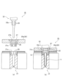
また、ブローキャビティ型51および底型52の間の第3摺動面には、固定潤滑剤28が埋設されている。この摺動面に固定潤滑剤28を埋設することで、ブローキャビティ型51および底型52における金型部品のかじりを抑制できる。なお、図5では図示を省略しているが、ブローキャビティ型51とネック型27の外周面27aとの第1摺動面や、ネック型27の内周面27bとエア導入部材との第2摺動面にもそれぞれ固定潤滑剤28が埋設される。
Further, a fixed
例えば、図5(a)に示すように、底型52においてブローキャビティ型51と摺動する円筒状またはテーパ状の基端部(当接部)52aには、底型52の外周に沿って、複数の固定潤滑剤28が環状をなすように等間隔に埋設されている。一方、ブローキャビティ型51において底型52の基端部52aを受ける円筒状またはテーパ状の開口部51aには、開口部51aの内周(底型52の基端部52aを受ける座面)に沿って、複数の固定潤滑剤28が環状をなすように等間隔に埋設されている。
For example, as shown in FIG. 5(a), a cylindrical or tapered base end (abutting portion) 52a that slides with the
なお、底型52は、容器15の底面形状を規定する賦形部52cと、賦形部52cと基端部52aを接続する円筒状またはテーパ状の中継部52bと、中継部52bと基端部52aを接続し底型52の最大上昇位置を規定する段差部52dと、をさらに備える。基端部52aの直径は中継部52bの直径よりも大きい。一方、ブローキャビティ型51は、型閉じ時に中継部52bに臨む(相対する)部位に、円筒状またはテーパ状の第2の開口部51bをさらに備える。開口部51aの直径は第2の開口部51bの直径よりも大きい。中継部52bの外周面と第2の開口部51bの内周面には固定潤滑剤28が埋設されず、型閉じ時に所定の隙間が設けられるように構成され、隙間はエアベントとして機能する。
The
(取り出し部24)
取り出し部24は、ブロー成形部23で製造された容器の首部12をネック型27から開放し、容器をブロー成形装置20の外部へ取り出すように構成されている。(Takeout section 24)
The take-out
(ブロー成形方法の説明)
次に、本実施形態のブロー成形装置20によるブロー成形方法について説明する。
図6は、ブロー成形方法の工程を示すフローチャートである。(Explanation of blow molding method)
Next, a blow molding method using the
FIG. 6 is a flowchart showing the steps of the blow molding method.
(ステップS101:第1射出成形工程)
まず、射出成形部21において、射出キャビティ型31、射出コア型32および搬送機構26のネック型27で形成された型空間に射出装置25から樹脂材料を射出し、プリフォーム11が製造される。(Step S101: First injection molding process)
First, in the
その後、射出成形部21の金型が型開きされると、搬送機構26の回転板26aが所定角度回転し、ネック型27に保持されたプリフォーム11が、射出成形時の保有熱を含んだ状態で温度調整部22に搬送される。
Thereafter, when the mold of the
(ステップS102:温度調整工程)
続いて、温度調整部22において、プリフォーム11の温度を最終ブローに適した温度に近づけるための温度調整が行われる。(Step S102: Temperature adjustment step)
Subsequently, the
温度調整工程においては、まず、プリフォーム11がキャビティ型41の温調空間41a内に収容される。続いて、キャビティ型41に収容されたプリフォーム11にコア型42が挿入される。
なお、キャビティ型41およびコア型42はプリフォーム11の形状に対応しているため、プリフォーム11の形状は温度調整工程においても所望の形状のまま維持される。In the temperature adjustment process, first, the
Note that since the
温度調整工程においては、プリフォーム11がキャビティ型41およびコア型42に臨むことで、プリフォーム11はブロー成形に適した温度以下にならないように温度調整され、さらに射出成形時に生じた偏温も低減される。
その後、搬送機構26の回転板26aが所定角度回転し、ネック型27に保持された温度調整後のプリフォーム11が、ブロー成形部23に搬送される。In the temperature adjustment process, the
Thereafter, the
(ステップS103:ブロー成形工程)
続いて、ブロー成形部23において、容器15のブロー成形が行われる。
まず、ブローキャビティ型51を型閉じしてプリフォーム11を型空間に収容する。プリフォーム11が容器15より長い場合、ブローキャビティ型51の型閉じ前はプリフォーム11の底部と接触しない下方の位置で底型52を待機させる。そして、ブローキャビティ型51の型閉じ後に底型52を成形位置まで素早く上昇させる。(Step S103: Blow molding process)
Subsequently, the
First, the
ブローキャビティ型51と底型52の型閉じに前後して、エア導入部材(ブローコア)を下降させることで、プリフォーム11の首部12にエア導入部材が当接される。そして、延伸ロッドを降下させてプリフォーム11の底部を内面から抑えて、必要に応じて縦軸延伸を行いつつ、エア導入部材からブローエアを供給することで、型空間内のプリフォーム11を横軸延伸する。これにより、プリフォーム11は、ブローキャビティ型51および底型52の型空間に密着するように膨出して賦形され、容器15にブロー成形される。
By lowering the air introducing member (blow core) before and after closing the
(ステップS104:容器取り出し工程)
ブロー成形が終了すると、ブロー成形部23の金型が型開きされる。これにより、ブロー成形部23から容器15が移動可能となる。
続いて、搬送機構26の回転板26aが所定角度回転し、容器15が取り出し部24に搬送される。取り出し部24において、容器15の首部12がネック型27から開放され、容器15がブロー成形装置20の外部へ取り出される。(Step S104: Container removal step)
When the blow molding is completed, the mold of the
Subsequently, the
以上で、ブロー成形方法の一連の工程が終了する。その後、搬送機構26の回転板26aを所定角度回転させることで、上記のS101からS104の各工程が繰り返される。
This completes the series of steps of the blow molding method. Thereafter, by rotating the
本発明は、上記実施形態に限定されることなく、本発明の趣旨を逸脱しない範囲において、種々の改良並びに設計の変更を行ってもよい。 The present invention is not limited to the above embodiments, and various improvements and design changes may be made without departing from the spirit of the present invention.
上記実施形態においては、摺動する2つの金型部品の両方に固定潤滑剤28を埋設する例を説明した。しかし、摺動する2つの金型部品のいずれか一方にのみ固定潤滑剤28を埋設するようにしてもよい。また、例えば、射出成形金型において、ネック型27と射出キャビティ型31の第1摺動面あるいはネック型27と射出コア型32の第2摺動面の一方には固定潤滑剤を埋設し、他方には固定潤滑剤を埋設しない構成としてもよい。
In the above embodiment, an example has been described in which the fixed
また、例えば、本発明の金型が用いられるブロー成形装置20は、2回以上の射出成形で多層のプリフォーム11を成形する場合には、温度調整部22の前段に、射出成形部を複数設けるようにしてもよい(5または6つの成形ステーションを備えるホットパリソン方式のブロー成形装置)。さらに、温度調整部22が存在しない装置構成でも構わない(射出成形部21、ブロー成形部23および取り出し部24の3つの成形ステーションを備えるホットパリソン方式のブロー成形装置)。
For example, the
また、本実施形態の金型は、射出成形部を有さないブロー成形装置に適用されるものであってもよい。図7(A)は、2ステージ式(コールドパリソン式)のブロー成形装置20aの構成を模式的に示す図である。
Moreover, the mold of this embodiment may be applied to a blow molding apparatus that does not have an injection molding section. FIG. 7(A) is a diagram schematically showing the configuration of a two-stage (cold parison type)
ブロー成形装置20aは、プリフォーム供給部60と、ブロー成形部23と、加熱部62(広義の温度調整部22a)と、搬送機構26と、容器取り出し部61とを備える。加熱部62は、ループ状の加熱搬送路と、プリフォームの胴部をブロー適温まで加熱可能な赤外線ヒーター等の加熱装置(不図示)を備える。搬送機構26は、加熱部62に配置され、プリフォーム供給部60から受け取ったプリフォームを保持して搬送する第1の保持部材26a1と、加熱部62から受け取ったプリフォームをブロー成形部23に搬送する第2の保持部材26b1と、容器をブロー成形部23から容器取り出し機構61に搬送する第3の保持部材26c1と、を有する。なお、ブロー成形装置20aのブロー成形部23で使用される金型の構成は上記実施形態と同様である。
The
プリフォーム供給部60は、別の射出成形装置で製造されて予め準備されたプリフォーム(例えばPET製)を受け取り、第1の保持部材26a1に装填する。また、容器取り出し部61は、ブロー成形部23に隣り合って配置され、ブロー成形部23で製造されて第3の保持部材26c1により搬送された容器を受ける容器保持部(不図示)を有する。加熱部62は、第1の保持部材26a1に保持されたプリフォームを自転させながら加熱装置内を搬送させて加熱する。
The
ブロー成形装置20aでは、プリフォーム供給部60で供給されたプリフォームが加熱部62でブロー適温(例えば100~110℃)まで加熱され、その後、プリフォームはブロー成形部23に搬送される。ブロー成形部23では、プリフォームがブローキャビティ型51と底型52からなる金型に収容され、ブロー成形により賦形されて容器が製造される。ブロー成形後に、容器が容器取り出し部61に搬送される。
In the
さらに、本実施形態の金型は、ブロー成形部を有さない射出成形装置に適用されるものであってもよい。図7(B)は、2ステージ式の射出成形装置70の構成を模式的に示す図である。
Furthermore, the mold of this embodiment may be applied to an injection molding apparatus that does not have a blow molding section. FIG. 7(B) is a diagram schematically showing the configuration of a two-stage
射出成形装置70は、射出成形部21と、取り出し部71と、冷却部72(広義の温度調整部22a)と、搬送機構26とを備える。冷却部72は、プリフォームを収容しプリフォームの胴部を外側から冷却する冷却ポット(不図示)と、プリフォームの胴部の中空部に挿入されて胴部を内部から冷却するクーリングロッド(不図示)を備える。搬送機構26は、射出成形部21からプリフォームを冷却部72に搬送する第1の保持部材26a1と、冷却部72からプリフォームを取り出し部71に搬送する第2の保持部材26b1と、を有する。射出成形部21には射出装置25が接続されている。なお、射出成形装置70の射出成形部21で使用される金型の構成は上記実施形態と同様である。
The
射出成形装置70では、射出成形部21で型閉じ状態のネック型27、射出キャビティ型31および射出コア型32からなる金型の成形空間に射出装置25から樹脂材料(例えばPET)が導入され、プリフォームの射出成形が行われる。その後、高温状態(例えば胴部外表面が100~130℃の状態)で離型されたプリフォームが冷却部72に搬送される。冷却部72では、プリフォームが常温下で放置されてもヒケ等の収縮変形が発生しない程度(例えば胴部外表面が50~60℃以下の状態)まで冷却される。次いで、十分に冷却されたプリフォームが取り出し部71に搬送される。
In the
加えて、今回開示された実施形態は、全ての点で例示であって制限的なものではないと考えられるべきである。本発明の範囲は、上記した説明ではなくて特許請求の範囲によって示され、特許請求の範囲と均等の意味及び範囲内での全ての変更が含まれることが意図される。 In addition, the embodiments disclosed this time should be considered to be illustrative in all respects and not restrictive. The scope of the present invention is indicated by the claims rather than the above description, and it is intended that all changes within the meaning and range equivalent to the claims are included.
11…プリフォーム、12…首部、20,20a…ブロー成形装置、21…射出成形部、22…温度調整部、23…ブロー成形部、26…搬送機構、27…ネック型、28…固定潤滑剤、31…射出キャビティ型、32…射出コア型、41…キャビティ型、42…コア型、51…ブローキャビティ型、52…底型、70…射出成形装置
DESCRIPTION OF
Claims (4)
前記ネック型に挿入される第2の金型と、を備える金型であって、
前記ネック型と前記第1の金型との第1摺動面と、前記ネック型と前記第2の金型との第2摺動面の少なくとも一方に固定潤滑剤が埋設され、
前記金型は、前記プリフォームのブロー成形に用いるブロー成形金型である
金型。 a first mold that receives a neck mold that holds a neck of a bottomed resin preform, and in which the preform is housed;
a second mold inserted into the neck mold, the mold comprising:
A fixed lubricant is embedded in at least one of a first sliding surface between the neck mold and the first mold and a second sliding surface between the neck mold and the second mold,
The mold is a blow molding mold used for blow molding the preform.
前記第2摺動面の前記固定潤滑剤は、前記ネック型の内周面と前記第2の金型の表面の少なくとも一方に埋設される
請求項1に記載の金型。 The fixed lubricant of the first sliding surface is embedded in at least one of the outer peripheral surface of the neck mold and the surface of the first mold,
The mold according to claim 1, wherein the fixed lubricant of the second sliding surface is embedded in at least one of an inner circumferential surface of the neck mold and a surface of the second mold.
前記第1の金型と前記底型との第3摺動面に固定潤滑剤が埋設されている
請求項1または請求項2に記載の金型。 further comprising a bottom mold that is inserted into the first mold and defines the bottom shape of the blow-molded container;
The mold according to claim 1 or 2, wherein a fixed lubricant is embedded in a third sliding surface of the first mold and the bottom mold.
A blow molding device comprising the mold according to any one of claims 1 to 3 .
Applications Claiming Priority (3)
| Application Number | Priority Date | Filing Date | Title |
|---|---|---|---|
| JP2020015318 | 2020-01-31 | ||
| JP2020015318 | 2020-01-31 | ||
| PCT/JP2021/003043 WO2021153671A1 (en) | 2020-01-31 | 2021-01-28 | Mold, blow molding device, and injection molding device |
Publications (3)
| Publication Number | Publication Date |
|---|---|
| JPWO2021153671A1 JPWO2021153671A1 (en) | 2021-08-05 |
| JPWO2021153671A5 JPWO2021153671A5 (en) | 2022-09-21 |
| JP7344993B2 true JP7344993B2 (en) | 2023-09-14 |
Family
ID=77079130
Family Applications (1)
| Application Number | Title | Priority Date | Filing Date |
|---|---|---|---|
| JP2021574108A Active JP7344993B2 (en) | 2020-01-31 | 2021-01-28 | Mold and blow molding equipment |
Country Status (5)
| Country | Link |
|---|---|
| US (1) | US20230049178A1 (en) |
| EP (1) | EP4098422A4 (en) |
| JP (1) | JP7344993B2 (en) |
| CN (1) | CN115038567A (en) |
| WO (1) | WO2021153671A1 (en) |
Citations (7)
| Publication number | Priority date | Publication date | Assignee | Title |
|---|---|---|---|---|
| JP3001055U (en) | 1994-02-15 | 1994-08-16 | 武雄 角岡 | Slide core and its guide rail in injection molding machine |
| JP2013154622A (en) | 2012-01-31 | 2013-08-15 | Nissei Asb Mach Co Ltd | Mold device, injection molding apparatus, and injection molding method |
| JP2014091321A (en) | 2012-10-31 | 2014-05-19 | Hidetoshi Otani | Self-lubrication sliding body |
| JP2014151562A (en) | 2013-02-08 | 2014-08-25 | Honda Motor Co Ltd | Mold for plastic molding and injection molding method |
| JP2018016344A (en) | 2016-07-27 | 2018-02-01 | 東洋製罐株式会社 | Synthetic resin container, and manufacturing method for the same |
| WO2018159745A1 (en) | 2017-03-02 | 2018-09-07 | 日精エー・エス・ビー機械株式会社 | Molding mold |
| CN109822791A (en) | 2019-02-28 | 2019-05-31 | 厦门市松竹精密科技有限公司 | A kind of ejecting type slide block device of mold |
Family Cites Families (6)
| Publication number | Priority date | Publication date | Assignee | Title |
|---|---|---|---|---|
| JPS60134615A (en) | 1983-12-23 | 1985-07-17 | Nec Corp | Voltage controlled attenuator |
| JPH01320121A (en) * | 1988-06-22 | 1989-12-26 | Sankyo Eng Kk | Built-in lubrication mold for injection molding |
| JP3573374B2 (en) * | 1995-05-08 | 2004-10-06 | 株式会社青木固研究所 | Preform molding method in injection stretch blow molding |
| DE202006011657U1 (en) * | 2006-07-26 | 2006-12-14 | Mht Mold & Hotrunner Technology Ag | Guide column bearing, e.g. for moving platens on injection molding machine, includes lubrication with viscous lubricant in addition to a solid lubricant |
| JP4819178B1 (en) * | 2010-10-27 | 2011-11-24 | 株式会社タカノ | Lubricating member and manufacturing method thereof |
| FR3078648B1 (en) * | 2018-03-07 | 2020-02-14 | Sidel Participations | LOCKING FINGER FOR A THERMOPLASTIC CONTAINER MOLDING UNIT |
-
2021
- 2021-01-28 US US17/795,439 patent/US20230049178A1/en active Pending
- 2021-01-28 WO PCT/JP2021/003043 patent/WO2021153671A1/en unknown
- 2021-01-28 CN CN202180011705.1A patent/CN115038567A/en active Pending
- 2021-01-28 EP EP21747411.3A patent/EP4098422A4/en active Pending
- 2021-01-28 JP JP2021574108A patent/JP7344993B2/en active Active
Patent Citations (7)
| Publication number | Priority date | Publication date | Assignee | Title |
|---|---|---|---|---|
| JP3001055U (en) | 1994-02-15 | 1994-08-16 | 武雄 角岡 | Slide core and its guide rail in injection molding machine |
| JP2013154622A (en) | 2012-01-31 | 2013-08-15 | Nissei Asb Mach Co Ltd | Mold device, injection molding apparatus, and injection molding method |
| JP2014091321A (en) | 2012-10-31 | 2014-05-19 | Hidetoshi Otani | Self-lubrication sliding body |
| JP2014151562A (en) | 2013-02-08 | 2014-08-25 | Honda Motor Co Ltd | Mold for plastic molding and injection molding method |
| JP2018016344A (en) | 2016-07-27 | 2018-02-01 | 東洋製罐株式会社 | Synthetic resin container, and manufacturing method for the same |
| WO2018159745A1 (en) | 2017-03-02 | 2018-09-07 | 日精エー・エス・ビー機械株式会社 | Molding mold |
| CN109822791A (en) | 2019-02-28 | 2019-05-31 | 厦门市松竹精密科技有限公司 | A kind of ejecting type slide block device of mold |
Also Published As
| Publication number | Publication date |
|---|---|
| WO2021153671A1 (en) | 2021-08-05 |
| US20230049178A1 (en) | 2023-02-16 |
| JPWO2021153671A1 (en) | 2021-08-05 |
| CN115038567A (en) | 2022-09-09 |
| EP4098422A1 (en) | 2022-12-07 |
| EP4098422A4 (en) | 2024-03-27 |
Similar Documents
| Publication | Publication Date | Title |
|---|---|---|
| EP3476567B1 (en) | Injection molding unit and blow molding device provided with same | |
| EP3369550B1 (en) | Metal mould unit, blow moulding apparatus, and blow moulding method | |
| JP7457077B2 (en) | Manufacturing method of bent-neck container, temperature adjustment mold, blow molding device, and blow molding method | |
| CN113613862A (en) | Resin container production apparatus and production method | |
| US20230158728A1 (en) | Manufacturing method and manufacturing apparatus for delamination container | |
| JP7344993B2 (en) | Mold and blow molding equipment | |
| JP7437475B2 (en) | Manufacturing method for resin containers, temperature control molds and blow molding equipment | |
| WO2022181618A1 (en) | Temperature adjustment mold and device and method for producing resin container | |
| WO2022181627A1 (en) | Temperature regulating mold, and device and method for producing resin container | |
| CN114302800A (en) | Mold unit, blow molding device, and blow molding method | |
| EP4324620A1 (en) | Production method and production device for resin container | |
| JP7399301B2 (en) | blow molding equipment | |
| WO2023145775A1 (en) | Temperature regulating mold and method for producing resin container | |
| WO2023149330A1 (en) | Temperature regulating mold, and device and method for producing resin container | |
| WO2023157863A1 (en) | Temperature adjustment mold, temperature adjustment method, and resin container manufacturing device | |
| EP4249210A1 (en) | Method and device for producing resin container | |
| US20220134630A1 (en) | Container mold and method of manufacturing a container | |
| US20240116236A1 (en) | Method for manufacturing resin container and apparatus for manufacturing same | |
| WO2023282292A1 (en) | Method for producing resin container and temperature control device | |
| CN114555330A (en) | Method and apparatus for manufacturing resin container |
Legal Events
| Date | Code | Title | Description |
|---|---|---|---|
| A521 | Request for written amendment filed |
Free format text: JAPANESE INTERMEDIATE CODE: A523 Effective date: 20220815 |
|
| A621 | Written request for application examination |
Free format text: JAPANESE INTERMEDIATE CODE: A621 Effective date: 20220815 |
|
| A131 | Notification of reasons for refusal |
Free format text: JAPANESE INTERMEDIATE CODE: A131 Effective date: 20230404 |
|
| A521 | Request for written amendment filed |
Free format text: JAPANESE INTERMEDIATE CODE: A523 Effective date: 20230523 |
|
| A131 | Notification of reasons for refusal |
Free format text: JAPANESE INTERMEDIATE CODE: A131 Effective date: 20230606 |
|
| A521 | Request for written amendment filed |
Free format text: JAPANESE INTERMEDIATE CODE: A523 Effective date: 20230728 |
|
| TRDD | Decision of grant or rejection written | ||
| A01 | Written decision to grant a patent or to grant a registration (utility model) |
Free format text: JAPANESE INTERMEDIATE CODE: A01 Effective date: 20230808 |
|
| A61 | First payment of annual fees (during grant procedure) |
Free format text: JAPANESE INTERMEDIATE CODE: A61 Effective date: 20230904 |
|
| R150 | Certificate of patent or registration of utility model |
Ref document number: 7344993 Country of ref document: JP Free format text: JAPANESE INTERMEDIATE CODE: R150 |