JP7344480B2 - wireless sensor - Google Patents
wireless sensor Download PDFInfo
- Publication number
- JP7344480B2 JP7344480B2 JP2022519915A JP2022519915A JP7344480B2 JP 7344480 B2 JP7344480 B2 JP 7344480B2 JP 2022519915 A JP2022519915 A JP 2022519915A JP 2022519915 A JP2022519915 A JP 2022519915A JP 7344480 B2 JP7344480 B2 JP 7344480B2
- Authority
- JP
- Japan
- Prior art keywords
- power supply
- wireless sensor
- supply line
- power
- temperature detection
- Prior art date
- Legal status (The legal status is an assumption and is not a legal conclusion. Google has not performed a legal analysis and makes no representation as to the accuracy of the status listed.)
- Active
Links
Images


Classifications
-
- G—PHYSICS
- G01—MEASURING; TESTING
- G01K—MEASURING TEMPERATURE; MEASURING QUANTITY OF HEAT; THERMALLY-SENSITIVE ELEMENTS NOT OTHERWISE PROVIDED FOR
- G01K1/00—Details of thermometers not specially adapted for particular types of thermometer
- G01K1/02—Means for indicating or recording specially adapted for thermometers
- G01K1/024—Means for indicating or recording specially adapted for thermometers for remote indication
-
- B—PERFORMING OPERATIONS; TRANSPORTING
- B60—VEHICLES IN GENERAL
- B60L—PROPULSION OF ELECTRICALLY-PROPELLED VEHICLES; SUPPLYING ELECTRIC POWER FOR AUXILIARY EQUIPMENT OF ELECTRICALLY-PROPELLED VEHICLES; ELECTRODYNAMIC BRAKE SYSTEMS FOR VEHICLES IN GENERAL; MAGNETIC SUSPENSION OR LEVITATION FOR VEHICLES; MONITORING OPERATING VARIABLES OF ELECTRICALLY-PROPELLED VEHICLES; ELECTRIC SAFETY DEVICES FOR ELECTRICALLY-PROPELLED VEHICLES
- B60L5/00—Current collectors for power supply lines of electrically-propelled vehicles
- B60L5/40—Current collectors for power supply lines of electrically-propelled vehicles for collecting current from lines in slotted conduits
-
- B—PERFORMING OPERATIONS; TRANSPORTING
- B60—VEHICLES IN GENERAL
- B60L—PROPULSION OF ELECTRICALLY-PROPELLED VEHICLES; SUPPLYING ELECTRIC POWER FOR AUXILIARY EQUIPMENT OF ELECTRICALLY-PROPELLED VEHICLES; ELECTRODYNAMIC BRAKE SYSTEMS FOR VEHICLES IN GENERAL; MAGNETIC SUSPENSION OR LEVITATION FOR VEHICLES; MONITORING OPERATING VARIABLES OF ELECTRICALLY-PROPELLED VEHICLES; ELECTRIC SAFETY DEVICES FOR ELECTRICALLY-PROPELLED VEHICLES
- B60L3/00—Electric devices on electrically-propelled vehicles for safety purposes; Monitoring operating variables, e.g. speed, deceleration or energy consumption
- B60L3/12—Recording operating variables ; Monitoring of operating variables
-
- B—PERFORMING OPERATIONS; TRANSPORTING
- B60—VEHICLES IN GENERAL
- B60L—PROPULSION OF ELECTRICALLY-PROPELLED VEHICLES; SUPPLYING ELECTRIC POWER FOR AUXILIARY EQUIPMENT OF ELECTRICALLY-PROPELLED VEHICLES; ELECTRODYNAMIC BRAKE SYSTEMS FOR VEHICLES IN GENERAL; MAGNETIC SUSPENSION OR LEVITATION FOR VEHICLES; MONITORING OPERATING VARIABLES OF ELECTRICALLY-PROPELLED VEHICLES; ELECTRIC SAFETY DEVICES FOR ELECTRICALLY-PROPELLED VEHICLES
- B60L5/00—Current collectors for power supply lines of electrically-propelled vehicles
-
- B—PERFORMING OPERATIONS; TRANSPORTING
- B60—VEHICLES IN GENERAL
- B60L—PROPULSION OF ELECTRICALLY-PROPELLED VEHICLES; SUPPLYING ELECTRIC POWER FOR AUXILIARY EQUIPMENT OF ELECTRICALLY-PROPELLED VEHICLES; ELECTRODYNAMIC BRAKE SYSTEMS FOR VEHICLES IN GENERAL; MAGNETIC SUSPENSION OR LEVITATION FOR VEHICLES; MONITORING OPERATING VARIABLES OF ELECTRICALLY-PROPELLED VEHICLES; ELECTRIC SAFETY DEVICES FOR ELECTRICALLY-PROPELLED VEHICLES
- B60L53/00—Methods of charging batteries, specially adapted for electric vehicles; Charging stations or on-board charging equipment therefor; Exchange of energy storage elements in electric vehicles
- B60L53/10—Methods of charging batteries, specially adapted for electric vehicles; Charging stations or on-board charging equipment therefor; Exchange of energy storage elements in electric vehicles characterised by the energy transfer between the charging station and the vehicle
- B60L53/12—Inductive energy transfer
-
- G—PHYSICS
- G08—SIGNALLING
- G08C—TRANSMISSION SYSTEMS FOR MEASURED VALUES, CONTROL OR SIMILAR SIGNALS
- G08C17/00—Arrangements for transmitting signals characterised by the use of a wireless electrical link
- G08C17/02—Arrangements for transmitting signals characterised by the use of a wireless electrical link using a radio link
-
- H—ELECTRICITY
- H04—ELECTRIC COMMUNICATION TECHNIQUE
- H04Q—SELECTING
- H04Q9/00—Arrangements in telecontrol or telemetry systems for selectively calling a substation from a main station, in which substation desired apparatus is selected for applying a control signal thereto or for obtaining measured values therefrom
-
- B—PERFORMING OPERATIONS; TRANSPORTING
- B60—VEHICLES IN GENERAL
- B60M—POWER SUPPLY LINES, AND DEVICES ALONG RAILS, FOR ELECTRICALLY- PROPELLED VEHICLES
- B60M7/00—Power lines or rails specially adapted for electrically-propelled vehicles of special types, e.g. suspension tramway, ropeway, underground railway
-
- G—PHYSICS
- G01—MEASURING; TESTING
- G01K—MEASURING TEMPERATURE; MEASURING QUANTITY OF HEAT; THERMALLY-SENSITIVE ELEMENTS NOT OTHERWISE PROVIDED FOR
- G01K2215/00—Details concerning sensor power supply
-
- H—ELECTRICITY
- H02—GENERATION; CONVERSION OR DISTRIBUTION OF ELECTRIC POWER
- H02J—CIRCUIT ARRANGEMENTS OR SYSTEMS FOR SUPPLYING OR DISTRIBUTING ELECTRIC POWER; SYSTEMS FOR STORING ELECTRIC ENERGY
- H02J50/00—Circuit arrangements or systems for wireless supply or distribution of electric power
- H02J50/005—Mechanical details of housing or structure aiming to accommodate the power transfer means, e.g. mechanical integration of coils, antennas or transducers into emitting or receiving devices
-
- H—ELECTRICITY
- H02—GENERATION; CONVERSION OR DISTRIBUTION OF ELECTRIC POWER
- H02J—CIRCUIT ARRANGEMENTS OR SYSTEMS FOR SUPPLYING OR DISTRIBUTING ELECTRIC POWER; SYSTEMS FOR STORING ELECTRIC ENERGY
- H02J50/00—Circuit arrangements or systems for wireless supply or distribution of electric power
- H02J50/10—Circuit arrangements or systems for wireless supply or distribution of electric power using inductive coupling
-
- Y—GENERAL TAGGING OF NEW TECHNOLOGICAL DEVELOPMENTS; GENERAL TAGGING OF CROSS-SECTIONAL TECHNOLOGIES SPANNING OVER SEVERAL SECTIONS OF THE IPC; TECHNICAL SUBJECTS COVERED BY FORMER USPC CROSS-REFERENCE ART COLLECTIONS [XRACs] AND DIGESTS
- Y02—TECHNOLOGIES OR APPLICATIONS FOR MITIGATION OR ADAPTATION AGAINST CLIMATE CHANGE
- Y02T—CLIMATE CHANGE MITIGATION TECHNOLOGIES RELATED TO TRANSPORTATION
- Y02T10/00—Road transport of goods or passengers
- Y02T10/60—Other road transportation technologies with climate change mitigation effect
- Y02T10/70—Energy storage systems for electromobility, e.g. batteries
-
- Y—GENERAL TAGGING OF NEW TECHNOLOGICAL DEVELOPMENTS; GENERAL TAGGING OF CROSS-SECTIONAL TECHNOLOGIES SPANNING OVER SEVERAL SECTIONS OF THE IPC; TECHNICAL SUBJECTS COVERED BY FORMER USPC CROSS-REFERENCE ART COLLECTIONS [XRACs] AND DIGESTS
- Y02—TECHNOLOGIES OR APPLICATIONS FOR MITIGATION OR ADAPTATION AGAINST CLIMATE CHANGE
- Y02T—CLIMATE CHANGE MITIGATION TECHNOLOGIES RELATED TO TRANSPORTATION
- Y02T10/00—Road transport of goods or passengers
- Y02T10/60—Other road transportation technologies with climate change mitigation effect
- Y02T10/7072—Electromobility specific charging systems or methods for batteries, ultracapacitors, supercapacitors or double-layer capacitors
-
- Y—GENERAL TAGGING OF NEW TECHNOLOGICAL DEVELOPMENTS; GENERAL TAGGING OF CROSS-SECTIONAL TECHNOLOGIES SPANNING OVER SEVERAL SECTIONS OF THE IPC; TECHNICAL SUBJECTS COVERED BY FORMER USPC CROSS-REFERENCE ART COLLECTIONS [XRACs] AND DIGESTS
- Y02—TECHNOLOGIES OR APPLICATIONS FOR MITIGATION OR ADAPTATION AGAINST CLIMATE CHANGE
- Y02T—CLIMATE CHANGE MITIGATION TECHNOLOGIES RELATED TO TRANSPORTATION
- Y02T90/00—Enabling technologies or technologies with a potential or indirect contribution to GHG emissions mitigation
- Y02T90/10—Technologies relating to charging of electric vehicles
- Y02T90/14—Plug-in electric vehicles
Landscapes
- Engineering & Computer Science (AREA)
- Mechanical Engineering (AREA)
- Physics & Mathematics (AREA)
- General Physics & Mathematics (AREA)
- Power Engineering (AREA)
- Transportation (AREA)
- Computer Networks & Wireless Communication (AREA)
- Life Sciences & Earth Sciences (AREA)
- Sustainable Development (AREA)
- Sustainable Energy (AREA)
- Current-Collector Devices For Electrically Propelled Vehicles (AREA)
- Arrangements For Transmission Of Measured Signals (AREA)
Description
本発明は、移動体システムにおいて状態量を取得する無線センサに関する。 The present invention relates to a wireless sensor that acquires state quantities in a mobile system.
従来から、例えば搬送台車システムにおいて、レールに沿って走行する搬送台車に給電するための給電線の継ぎ目部分に対して、温度センサを含むセンサデバイスを配置する構成が知られている。特許文献1は、この種の構成を有する搬送車システムを開示する。
BACKGROUND ART Conventionally, for example, in a transportation vehicle system, a configuration is known in which a sensor device including a temperature sensor is arranged at a joint portion of a power supply line for supplying power to a transportation vehicle traveling along a rail.
特許文献1の搬送車システムは、温度センサにより端子台に電気的に接続された複数本(例えば、4本)の給電線のそれぞれの温度を検出し、検出基板により取得した温度データを無線で送信する構成となっている。
The guided vehicle system of
特許文献1に開示された温度センサ及び検出基板を動作させるには、電力を供給する必要がある。このため、例えば給電ケーブルの配線工事等を行う必要があるが、かかる工事により搬送車システムを長時間停止しなければならない場合がある。半導体製造工場等においては、搬送車システムの停止は避けるべきである。従って、既存のシステムに温度センサを後付け的に取り付けることが困難であった。
In order to operate the temperature sensor and detection board disclosed in
本発明は以上の事情に鑑みてされたものであり、その目的は、容易に電源を得ることができ、既存の移動体システムへの後付けが容易な無線センサを提供することにある。 The present invention has been made in view of the above circumstances, and its purpose is to provide a wireless sensor that can easily obtain power and that can be easily retrofitted to existing mobile systems.
本発明の解決しようとする課題は以上の如くであり、次にこの課題を解決するための手段とその効果を説明する。 The problem to be solved by the present invention is as described above, and next, the means for solving this problem and the effects thereof will be explained.
本発明の第1の観点によれば、以下の構成の無線センサが提供される。即ち、この無線センサは、移動体が給電線から非接触で電力を得る移動体システムに関する状態量を測定し、測定された状態量を無線で送信する。前記無線センサは、非接触受電部と、測定部と、無線送信部と、を備える。前記非接触受電部は、前記給電線から非接触で電力を得る。前記測定部は、前記非接触受電部から供給される電力により動作し、前記移動体システムの被測定部位における前記状態量を測定する。前記無線送信部は、前記非接触受電部から供給される電力により動作し、前記測定部により測定された状態量を無線送信する。前記非接触受電部は、片側が開放されたE型コアである。前記E型コアに対して前記給電線の位置が固定されている。 According to a first aspect of the present invention, a wireless sensor having the following configuration is provided. That is, this wireless sensor measures a state quantity related to a mobile system in which a mobile body obtains power from a power supply line in a non-contact manner, and wirelessly transmits the measured state quantity. The wireless sensor includes a contactless power receiving section, a measuring section, and a wireless transmitting section. The contactless power receiving unit obtains power from the power supply line in a contactless manner. The measurement unit operates using electric power supplied from the non-contact power receiving unit, and measures the state quantity at the measurement target site of the mobile system. The wireless transmitter operates using power supplied from the non-contact power receiver, and wirelessly transmits the state quantity measured by the measurement unit. The non-contact power receiving section is an E-shaped core with one side open. The position of the feeder line is fixed with respect to the E-shaped core.
これにより、無線センサは、移動体システムに予め備えられている給電線から、電力を非接触で得ることができる。従って、特別な電源等を設けることなく、無線センサの被測定部位への後付けを容易に行うことができる。即ち、既存の移動体システムに対して、状態量測定機能を簡単に追加することができる。更に、十分な電力を容易に得ることができる。また、給電線を容易に非接触受電部に装着することができる。 Thereby, the wireless sensor can contactlessly obtain power from the power supply line provided in advance in the mobile system. Therefore, the wireless sensor can be easily retrofitted to the part to be measured without providing a special power source or the like. That is, a state quantity measurement function can be easily added to an existing mobile system. Furthermore, sufficient power can be easily obtained. Further, the power supply line can be easily attached to the non-contact power receiving unit.
前記の無線センサは、前記状態量として温度を測定することが好ましい。 Preferably, the wireless sensor measures temperature as the state quantity.
これにより、被測定部位の温度を監視することができる。 Thereby, the temperature of the part to be measured can be monitored.
前記の無線センサは、前記状態量として、前記温度に加え、前記給電線の電圧を測定することが好ましい。 It is preferable that the wireless sensor measures the voltage of the power supply line in addition to the temperature as the state quantity.
これにより、給電線の電圧を監視することができる。 Thereby, the voltage of the power supply line can be monitored.
前記の無線センサにおいて、前記被測定部位は、前記給電線が電気的に接続される端子台と当該給電線との接続部、又は当該接続部の近傍であることが好ましい。 In the above-mentioned wireless sensor, it is preferable that the part to be measured is a connection part between a terminal block to which the power supply line is electrically connected and the power supply line, or a vicinity of the connection part.
これにより、接続部における電気的な導通不良で高温となり易い場所を対象として、温度を監視することができる。 Thereby, it is possible to monitor the temperature in a location where high temperatures are likely to occur due to poor electrical continuity at the connection portion.
前記の無線センサにおいては、以下の構成とすることが好ましい。即ち、前記端子台は、金属製の筐体の内部に設けられている。前記無線送信部は、前記筐体の外側に配置されている。 The wireless sensor described above preferably has the following configuration. That is, the terminal block is provided inside a metal housing. The wireless transmitter is arranged outside the housing.
これにより、無線送信部が外部と無線通信を行うのに好適な環境を実現することができる。 Thereby, it is possible to realize an environment suitable for the wireless transmitter to perform wireless communication with the outside.
前記の無線センサにおいては、以下の構成とすることが好ましい。即ち、この無線センサは、前記非接触受電部の位置を固定する取付部を備える。前記取付部は、前記給電線と前記E型コアの相対位置を決める。 The wireless sensor described above preferably has the following configuration. That is, this wireless sensor includes a mounting part that fixes the position of the non-contact power receiving part. The attachment portion determines the relative position of the power supply line and the E-shaped core.
これにより、給電線の位置を固定することができ、電力を安定的に得ることができる。 Thereby, the position of the power supply line can be fixed, and electric power can be stably obtained.
本発明の第2の観点によれば、以下の構成の移動体システムが提供される。即ち、この移動体システムは、前記無線センサと、複数の移動体と、管理装置と、を備える。前記複数の移動体は、前記給電線から非接触で電力を得る。前記管理装置は、前記無線センサにより測定された状態量を収集する。前記無線センサは、測定された状態量を無線通信により前記管理装置へ送信する。 According to a second aspect of the present invention, a mobile system having the following configuration is provided. That is, this mobile system includes the wireless sensor, a plurality of mobile bodies, and a management device. The plurality of moving bodies obtain power from the power supply line in a non-contact manner. The management device collects state quantities measured by the wireless sensor. The wireless sensor transmits the measured state quantity to the management device by wireless communication.
これにより、管理装置は、無線センサにより測定された状態量を容易に取得することができる。無線センサは、移動体システムに予め備えられた給電線から電力を非接触で得ることができる。従って、新たに電気配線を行う必要がなく、移動体システムの電気配線を簡潔にすることができる。 Thereby, the management device can easily acquire the state quantity measured by the wireless sensor. A wireless sensor can obtain power without contact from a power supply line provided in advance in a mobile system. Therefore, there is no need to perform new electrical wiring, and the electrical wiring of the mobile system can be simplified.
次に、図面を参照して本発明の実施の形態を説明する。図1は、本発明の一実施形態に係る搬送台車システム100の概略な構成を示す模式図である。図2は、端子ボックス4の内部の構成を示す模式図である。図3は、端子ボックス4が取り付けられたレール1の部分を詳細に示す斜視図である。図4は、第1ケース部61及びE型コア63の構成を示す斜視図である。図5は、装置給電部6の構成を示す分解斜視図である。
Next, embodiments of the present invention will be described with reference to the drawings. FIG. 1 is a schematic diagram showing a general configuration of a
図1に示す搬送台車システム(移動体システム)100は、搬送台車2により荷物を搬送することができる。搬送台車2は、天井側に設置されたレール1に沿って走行する。搬送台車システム100は、例えば、複数の処理装置(図略)を有する半導体製造工場や、複数のスタッカラック(図略)を有する自動倉庫等において用いられる。
The carrier system (mobile system) 100 shown in FIG. 1 can transport cargo using the
レール1は、例えば半導体製造工場等の天井から吊り下げられた状態で設置されている。搬送台車2としては、例えば、OHT(即ち、天井走行車)を用いることができる。OHTとは、Overhead Hoist Transferの略称である。
The
搬送台車2は、電力供給装置3から供給される電力を、レール1に沿って敷設された給電経路30を介して、電磁誘導により非接触で得ることができる。これにより、搬送台車2は、給電経路30からの電力の供給を受けながら、レール1に沿って走行することができる。
The
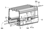
給電経路30は、略平行に配置された複数対の給電線31を有している。それぞれの給電線31は、細長い複数の導電線要素が長手方向で互いに接続された構成となっている。複数の継ぎ目部分の各々には、図2に示す端子ボックス4が配置されている。
The
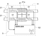
端子ボックス4の内部には、図2及び図3に示すように、端子台41と、本実施形態の温度センサ装置(無線センサ)5と、が配置されている。
Inside the
端子台41は、図2に示すように、筐体41a内に配置される。筐体41aは、例えば金属製とすることができる。端子台41は、1対の給電線31において、給電のための電流が流れる導電線要素同士を電気的に相互に接続するために用いられる。
The
温度センサ装置5は、端子台41の近傍に配置されている。温度センサ装置5は、端子台41の近傍の給電線31の温度を検出するために用いられる。
The
温度センサ装置5は、センサ本体(測定部)51と、温度検出基板(無線送信部)52と、装置給電部6と、を備える。
The
センサ本体51は、例えば、温度センサから構成される。センサ本体51は、端子台41の近傍の給電線31の温度(状態量)を検出する。即ち、温度センサ装置5による被測定部位は、給電線31のうち端子台41の近傍に位置する部分である。なお、センサ本体51は、給電線31と端子台41との接続部近傍に設けられ、当該接続部近傍における温度を検出しても良い。
The sensor
センサ本体51は、端子台41の近傍の給電線31の温度に加え、給電線31における電圧を検出するものであっても良い。かかる構成においては、端子台41の近傍の給電線31の温度及び給電線31における電圧が前記状態量に相当する。
The sensor
本実施形態においては、図2に示すように、4本の導電線要素が、端子台41から紙面向かって左右方向にそれぞれ2本ずつ延在するように設けられている。センサ本体51は、図2に示すように、左右2本ずつの導電線要素のそれぞれについて、端子台41による電気的な接続箇所を挟んで2つ配置されている。4つのセンサ本体51は、それぞれの部分の温度を検出する。
In this embodiment, as shown in FIG. 2, four conductive wire elements are provided such that two conductive wire elements each extend from the
各センサ本体51は、温度の検出結果を、温度検出基板52へ有線で出力する。各センサ本体51は、温度検出基板52から供給される電力で動作する。即ち、各センサ本体51は、装置給電部6から温度検出基板52を介して供給される電力で動作する。
Each sensor
温度検出基板52は、端子台41から少し離れた位置に設けられている。この温度検出基板52は、端子台41を収容する筐体41aの外部に位置する。これにより、温度検出基板52による外部装置との間の無線通信が、金属製の筐体41aによって遮断されないようにすることができる。
The
温度検出基板52は、電線等を介して装置給電部6と電気的に接続され、装置給電部6から供給される電力で動作する。温度検出基板52は、各センサ本体51から供給される検出結果を後述の管理装置9へ送信する。
The
センサ本体51に加え、端子台41からある程度離れた部位(例えば筐体41aの外側)に外気温センサを設け、当該外気温センサにより検出される外気温を後述の管理装置9へ別途送信するものであってもよい。あるいは、センサ本体51により検出される端子台41の近傍の給電線31の温度と、外気温センサにより検出される外気温との差分温度を後述の管理装置9へ送信するものであってもよい。この態様において、管理装置9は、かかる差分温度に基づいて異常の発生を判断する。また、外気温センサは、装置給電部6から温度検出基板52を介して供給される電力で動作する。
In addition to the
次に、本実施形態の搬送台車システム100における、複数の温度検出基板52同士の間、及び温度検出基板52と管理装置9との間の通信について、図6等を参照して簡単に説明する。図6は、温度検出基板52と管理装置9との間の通信を示す説明図である。図6に示す温度検出基板52a~52gは、前述の温度検出基板52の一例である。以下、これら温度検出基板52a~52gを特に区別しない場合には、単に温度検出基板52と称する。
Next, communication between the plurality of
本実施形態の複数の温度検出基板52のそれぞれは、中継機能を有し、適宜の間隔をあけて設けられている。温度検出基板52は、他の温度検出基板52の中継機として用いられ、より遠くまでデータを伝送できるマルチホップ通信を実現する。
Each of the plurality of
具体的には、温度検出基板52は、他の温度検出基板52同士との間で無線通信可能に構成されている。温度検出基板52は、他の温度検出基板52との無線通信により、他の温度検出基板52からの温度の検出結果を取得する。温度検出基板52は、取得した他の温度検出基板52の検出結果及び自身の検出結果を更に他の温度検出基板52又は管理装置9に送信する。
Specifically, the
温度検出基板52は、取得した他の温度検出基板52の検出結果及び自身の検出結果を更に他の温度検出基板52に無線送信する場合、他の温度検出基板52同士の間の無線通信における中継機として機能する。温度検出基板52は、取得した他の温度検出基板52の検出結果及び自身の検出結果を管理装置9に送信する場合、他の温度検出基板52と管理装置9との間の無線通信における中継機として機能する。
When the
図6に示すように、温度検出基板52a~52gは、設けられた位置等に応じて、他の温度検出基板52との間でそれぞれ異なる態様の無線通信を行う。温度検出基板52a、52b、52cは、Wi-Fi等によるメッシュネットワークを構成し、相互に所謂メッシュ通信を行う。特に、管理装置9に有線接続された温度検出基板52aと、その近傍に配置された複数の温度検出基板52(図6では温度検出基板52b、52c)との間でかかるメッシュ通信が行われることが好ましい。
As shown in FIG. 6, the
温度検出基板52bは、温度検出基板52d、52eとの間で、それぞれWi-Fiによる無線通信を行う。また、温度検出基板52cは、温度検出基板52f、52gとの間で、それぞれWi-Fiによる無線通信を行う。このように、前記メッシュネットワークを構成する温度検出基板52a、52b、52cは、それぞれの近傍に配置された複数の温度検出基板52との間で、メッシュネットワークを構成しない所謂スター型の無線通信を行う。
The
温度検出基板52dは、温度検出基板52eとの間でBluetooth(登録商標)による無線通信を行う。また、温度検出基板52fは、温度検出基板52gとの間でBluetoothによる無線通信を行う。このように、前記メッシュネットワークを構成する温度検出基板52a~52cと所謂スター型の無線通信を行う複数の温度検出基板52d~52g同士は、Bluetoothによる無線通信を行う。
The
複数の通信装置が相互に無線通信する通信システムでは、送信時にパケットの衝突が発生するおそれがある。Wi-Fi通信においては、CSMA/CA方式等の仕組みによりパケット同士の衝突を回避できるが、Bluetoothに基づく無線通信ではかかる仕組みがなく、各通信装置が独自の判断でパケットを送信してしまい、パケット同士の衝突が発生するおそれがある。 In a communication system in which a plurality of communication devices communicate wirelessly with each other, there is a risk that packet collisions will occur during transmission. In Wi-Fi communication, collisions between packets can be avoided using a mechanism such as the CSMA/CA method, but wireless communication based on Bluetooth does not have such a mechanism, and each communication device sends packets based on its own judgment. Collision between packets may occur.
そこで、本実施例の温度検出基板52は、Wi-Fi通信により他の温度検出基板52と無線通信可能に構成されるとともに、Bluetooth通信により他の温度検出基板52と無線通信可能に構成されている。そして、他の温度検出基板52から、Bluetooth通信を介して検出結果を含むパケットを受信した場合、その検出結果を含むパケットを受信した時刻に基づいて、自機がWi-Fi通信によりパケットを送信するタイミングを調整する。この際、当該Wi-Fi通信により送信されるパケットに、前記他の温度検出基板52から受信した前記検出結果を含める。
Therefore, the
これにより、例えば図6に示す例において、前記メッシュネットワークを構成する温度検出基板52bに温度検出基板52dが送信すべき検出結果を、パケット同士の衝突を抑制しつつ、温度検出基板52eが代替的に温度検出基板52bに送信することができる。
As a result, in the example shown in FIG. 6, for example, the
管理装置9は、例えば、パーソナルコンピュータ、サーバ装置、タブレット端末、スマートフォン等から構成される。管理装置9は、温度検出基板52aと有線/無線で接続され、温度検出基板52aとの通信に基づいて、温度センサ装置5の検出結果を取得する。このように、管理装置9は、温度検出基板52aとの通信を介して、温度センサ装置5から取得された検出結果を収集する。得られたデータに基づいて、管理装置9は、搬送台車システム100の異常(例えば、端子台41の近傍の温度異常)が発生しているか否かを監視する。
The
上述のように、温度検出基板52同士の間の無線通信等を介して、センサ本体51により検出された検出結果が他の温度検出基板52に即時に共有され、管理装置9により収集される。これにより、管理装置9は、端子台41における電気的接続の不良等によって高温になり易い端子台41の近傍の温度を、リアルタイムで監視することができる。
As described above, the detection results detected by the
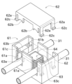
装置給電部6は、図5に示すように、主として、第1ケース部61と、第2ケース部62と、E型コア(非接触受電部)63と、を備える。この第1ケース部61及び第2ケース部62は、本実施形態の取付部を構成する。
As shown in FIG. 5, the device
第1ケース部61は、例えば、合成樹脂から形成される。第1ケース部61は、一側が開放された中空の箱状に形成されている。第2ケース部62は、この開放側から第1ケース部61に取り付けられる。
The
第1ケース部61は、第2ケース部62が第1ケース部61に取り付けられる方向で見た場合、長方形に形成されている。第1ケース部61は、給電線31の軸方向で見た場合、E字状に形成されている。
The
第1ケース部61には、切欠部61aと、ケース固定部61bと、E型コア嵌合部61cと、が形成されている。
The
切欠部61aは、第1ケース部61における側壁部が一側(上側)を開放するように切り欠かれることにより形成されている。切欠部61aの開放側は、第1ケース部61における開放側と同じである。切欠部61aは、給電線31の軸方向において、第1ケース部61(側壁部)を貫通するように形成されている。これにより、切欠部61aに給電線31を通すことができる。切欠部61aにおける幅方向の寸法は、給電線31の径寸法と略同等か、それよりもわずかに大きい。これにより、切欠部61aに通された給電線31の、切欠部61aの幅方向における移動が規制され、その位置が定められる。
The
切欠部61aは、所定の間隔をあけて2つ並べて形成されている。2本の給電線31のそれぞれは、対応する切欠部61aに嵌め入れることができる。それぞれの切欠部61aには、図5に示すように、給電線31の一部を収容することができる。
Two
ケース固定部61bは、第1ケース部61の4隅のそれぞれに1つずつ設けられている。ケース固定部61bは、後述の取付片62aを挿入可能な角筒状に形成されている。ケース固定部61bの内部には、例えば、図略の引掛け部が設けられており、挿入された取付片62aの爪部62cを引っ掛けることができる。これにより、取付片62aがケース固定部61bから抜けないように固定することができる。
One
E型コア嵌合部61cは、第1ケース部61の内部に配置され、細長く延びる溝状に形成されている。この溝の長手方向は、給電線31の長手方向と垂直である。また、溝の長手方向は、2つの切欠部61aが並ぶ方向と一致する。E型コア嵌合部61cは、E型コア63の一部を収容する。図5に示すようにE型コア63がE型コア嵌合部61cに嵌合されることで、E型コア63の位置が固定される。
The E-shaped core
第2ケース部62は、例えば、合成樹脂から形成される。第2ケース部62は、第1ケース部61に嵌合して、E字状の第1ケース部61の開放部分を閉じるカバーとして機能する。これにより、図5に示すように、第2ケース部62と第1ケース部61との間には、給電線31を差込可能な通過路が形成される。
The
第2ケース部62は、図5に示すように、概ね板状に形成されている。第2ケース部62は、第1ケース部61と対面する方向で見た場合、第1ケース部61より若干小さい長方形に形成されている。
The
第2ケース部62は、4つの取付片62aと、4つの押え片62bと、を備える。
The
取付片62aは、第2ケース部62を第1ケース部61に固定するために用いられる。取付片62aは、第2ケース部62の4隅のそれぞれにおいて、第1ケース部61に向かって突出するように形成されている。取付片62aは、2本の給電線31が並ぶ方向における第2ケース部62の両端のそれぞれに、2本ずつ設けられている。
The
取付片62aの先端には、小さな爪部62cが設けられている。この爪部62cは、2本の給電線31が並ぶ方向において、第2ケース部62の中央から遠ざかる向きに突出している。爪部62cは、取付片62aの先端の一部がL字状に折り曲げられるように形成されている。
A
図5に示すように、第2ケース部62を第1ケース部61に取り付ける場合、4つの取付片62aは、第1ケース部61に形成されたケース固定部61b内に挿入される。ケース固定部61b内に挿入された取付片62aの爪部62cが図略の引掛け部に引っ掛かることで、第2ケース部62が第1ケース部61に固定される。
As shown in FIG. 5, when attaching the
押え片62bは、第1ケース部61の切欠部61aに通された給電線31の位置を固定するために用いられる。図5に示すように、押え片62bは、第1ケース部61の切欠部61aに対応する位置に設けられている。
The holding
押え片62bは、給電線31の軸方向において、第2ケース部62の両側に2つずつ設けられている。即ち、1本の給電線31に対して、その軸方向で異なる2箇所に配置された押え片62bによって、当該給電線31が押さえられる。更に、切欠部61aの幅寸法が上述のように構成されていることで、切欠部61aに通された給電線31の、切欠部61aの幅方向における移動が規制される。即ち、給電線31が切欠部61aに通された状態で、第1ケース部61に第2ケース部62が取り付けられることで、第1ケース部61及び第2ケース部62(ひいてはE型コア63)に対して、給電線31の位置を固定することができる。
Two holding
押え片62bの先端部には、円弧状の凹部が形成されている。給電線31の軸方向で見た場合、円弧状の部分は、第1ケース部61から離れる方向へ凹むように形成されている。なお、以下の説明においては、円弧状の凹部の内面を円弧面と称する。
An arcuate recess is formed at the tip of the
第2ケース部62が第1ケース部61に嵌合した場合、押え片62bの円弧面が、第1ケース部61の切欠部61aに設置された給電線31の外周面の一部と接触する。これにより、2本の給電線31が並ぶ方向における当該給電線31の動きを規制することができる。
When the
上述のように、E型コア63の位置が第1ケース部61により固定される。一方、給電線31の位置は、第2ケース部62の押え片62b等により固定される。即ち、第1ケース部61及び第2ケース部62の組合せにより、給電線31とE型コア63との相対的な位置決めを行うことができる。この結果、安定した誘電電力を得ることができる。
As described above, the position of the
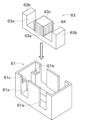
E型コア63は、例えばフェライト等の磁性材料から形成される。E型コア63は、図4及び図5に示すように、給電線31の軸方向で見たときにE字状に形成される。E型コア63には、2本の給電線31が並ぶ方向において適宜の間隔をあけて、2つのコア切欠部63aが並べて形成されている。2つのコア切欠部63aは、E型コア63の同じ側(片側)を開放させるように形成されている。E型コア63は、コア切欠部63aが切欠部61aと互いに対応するように、第1ケース部61の内部に嵌められている。
The
E型コア63は、図4に示すように、2本の外側突起63bと、中央突起63cと、を備える。
As shown in FIG. 4, the
外側突起63bは、E型コア63の長手方向両側外側のそれぞれに1本ずつ設けられている。
One
中央突起63cは、E型コア63の中央位置に設けられている。中央突起63cは、2つの外側突起63bの間に配置されている。中央突起63cの外周面には、例えば銅線からなる巻き線64が配置されている。この巻き線64は、2次コイルに相当する。
The
E型コア63のコア切欠部63aのそれぞれに設置される給電線31の部分は、1次コイルに相当する。即ち、給電線31に交流電流を流すと、生成した磁束に比例した誘電電流が巻き線64に流れる。この電磁誘導により、給電線31から電力を非接触で得ることができる。
The portions of the
上述のように、本実施形態の温度センサ装置5は装置給電部6を備えているので、給電ケーブルの配線作業等を要することなく容易に取り付けることができる。また、端子台41の近傍において、2本の給電線31が第1ケース部61の切欠部61aのそれぞれに位置するように第1ケース部61を配置して、この第1ケース部61に第2ケース部62を嵌合することで、既存の端子台41に対して簡単に適用することができる。
As described above, since the
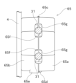
図7は、装置給電部6の別の一例について概観を示す図であり、図8は、その断面図である。以下、これら図7及び図8を用いて、装置給電部6の別の構成例について説明する。なお、以下の説明において、図5及び図6を用いて説明した実施形態と共通する部分については、同一の符号を付してその説明を省略する。
FIG. 7 is a diagram showing an overview of another example of the device
この構成例の装置給電部6は、ケース部65を備える。ケース部65は、第1ケース部65aと、第2ケース部65bと、を備える。第1ケース部65a及び第2ケース部65bは、ヒンジ部65cにおいて連結されており、当該ヒンジ部65cを支点として相互に回動し開閉可能とされている。第1ケース部65aにおけるヒンジ部65cとは反対側の端部には係合爪部65dが、第2ケース部65bにおけるヒンジ部65cとは反対側の端部には被係合部65eが、それぞれ設けられている。係合爪部65dが、被係合部65eに係合させられることで、第1ケース部65aと第2ケース部65bとが相互に嵌め合わされ、ヒンジ部65cを支点とする回動が不能となるように構成されている。
The device
第1ケース部65aと第2ケース部65bとが相互に嵌め合わされることで、ケース部65には1対の窓部65fが形成される。E型コア63のコア切欠部63aには、ウレタン樹脂等の電気絶縁体からなる充填材65gが設けられている。図7に示すように、窓部65fに相当する位置に給電線31が挿入された状態で、第1ケース部65aと第2ケース部65bとが相互に嵌め合わされると、充填材65gが弾性変形させられるとともに、当該給電線31が窓部65fと充填材65gとの間で挟持され、その位置が規制されるようになっている。なお、図8においては、給電線31及び第1ケース部65a側の窓部65fを破線で示すとともに、充填材65gが弾性変形させられる前(力が加わっていない状態)の形状を例示している。
A pair of
図7に示すように、1対の給電線31が窓部65fと充填材65gとの間で挟持されることで、当該給電線31に対してケース部65が保持される。このため、ケース部65は、レール1、端子ボックス4等には固定されていない。図7及び図8においては、ケース部65における第2ケース部65bが端子ボックス4側となるように、ケース部65が1対の給電線31に取り付けられているが、第1ケース部65aが端子ボックス4側となるように取り付けられてもよい。
As shown in FIG. 7, the pair of
図8に示すように、第2ケース部65bにおける底部65hの厚み寸法tbは、第1ケース部65aにおける底部65jの厚み寸法taよりも大きい。かかる構成により、図8に示すようにケース部65(第2ケース部65b)と端子ボックス4とが最も接近した状態においても、E型コア63の開放端(外側突起63b及び中央突起63cが突出する側)は、端子ボックス4に対して少なくとも底部65hの厚み寸法tbに相当する距離を隔てて位置される。この厚み寸法tbは、E型コア63から発生させられる磁界が、端子ボックス4を構成する部材に渦電流を発生させるのを抑制するために必要十分な厚みとされる。
As shown in FIG. 8, the thickness tb of the bottom 65h of the
端子ボックス4は、例えばアルミニウム合金の導電体から構成される。このため、E型コア63の開放端が端子ボックス4に近接して設けられると、E型コア63から発生させられる磁界が、端子ボックス4を構成する導電性板材に渦電流を発生させ、電力ロスが発生して給電効率が低下するおそれがある。本構成例においては、第2ケース部65bにおける底部65hの厚み寸法tbが十分に大きく構成されていることで、ケース部65内に収容されるE型コア63の開放端と端子ボックス4との間に十分な距離を保つことができる。これにより、E型コア63により発生させられた磁界が、端子ボックス4を構成する導電性板材に渦電流を発生させるのを抑制でき、装置給電部6の給電効率低下を防止できる。
The
一方で、第1ケース部65aにおける底部65jの厚み寸法taは、第2ケース部65bにおける底部65hの厚み寸法tbよりも小さいが、E型コア63における基部側(開放端とは反対側)から外部に向けて発生させられる磁界は、開放端側から外部に向けて発生させられる磁界に比べて十分に小さいため、E型コア63における基部側に発生させられた磁界が周囲の導電性板材等に与える影響は小さい。このため、ケース部65が給電線31に対して、第1ケース部65aが端子ボックス4側となるように取り付けられた構成において、ケース部65(第1ケース部65a)と端子ボックス4とが最も接近した状態においても、E型コア63により発生させられた磁界が端子ボックス4を構成する部材に渦電流を発生させることはなく、装置給電部6の給電効率低下を防止できる。
On the other hand, the thickness ta of the bottom 65j in the
以上のように、本構成例によれば、ケース部65が給電線31に対して、第1ケース部65a及び第2ケース部65bの何れが端子ボックス4側となるように取り付けられても、E型コア63により発生させられた磁界が、端子ボックス4を構成する部材に渦電流を発生させるのを抑制でき、装置給電部6の給電効率低下を防止できる。このため、作業者はケース部65を給電線31に対して取り付ける際、第1ケース部65a及び第2ケース部65bの何れが端子ボックス4側となるように取り付けてもよく、その向きに気を払う必要がないため、取付効率が向上するという利点もある。
As described above, according to the present configuration example, even if the
なお、図7及び図8には図示していないが、ケース部65を給電線31に取り付けた状態において、ケース部65に対して端子ボックス4を構成する部材の反対側には、レール1に端子台41を取り付けるための取付部材が位置することになる。この取付部材は、例えば鉄材等の導電性板材から構成されている。鉄材はアルミニウム部材に比べて体積抵抗率が大きく、磁界が及んだ際に渦電流が流れにくいものの、E型コア63により発生させられた磁界が及ぶことで渦電流が発生させられるおそれがある。しかしながら、上述のように本構成例のケース部65においては、第1ケース部65a及び第2ケース部65bのうち何れの側に導電性板材が接近しても渦電流の発生が抑制されるように構成されているため、端子ボックス4を構成する部材及び取付部材の何れにおいても渦電流の発生を抑制でき、装置給電部6の給電効率低下を防止できる。
Although not shown in FIGS. 7 and 8, when the
以上に説明したように、本実施形態の温度センサ装置5は、搬送台車2が給電線31から非接触で電力を得る搬送台車システム100に関する温度を測定し、測定された温度を無線で送信する。温度センサ装置5は、E型コア63と、センサ本体51と、温度検出基板52と、を備える。E型コア63は、給電線31から非接触で電力を得る。センサ本体51は、E型コア63から供給される電力により動作し、搬送台車システム100の被測定部位における温度を測定する。温度検出基板52は、E型コア63から供給される電力により動作し、センサ本体51により測定された温度を無線送信する。
As described above, the
これにより、温度センサ装置5は、搬送台車システム100に予め備えられている給電線31から、電力を非接触で得ることができる。従って、特別な電源等を設けることなく、温度センサ装置5の被測定部位への後付けを容易に行うことができる。即ち、既存の搬送台車システム100に対して、温度測定機能を簡単に追加することができる。
Thereby, the
また、本実施形態の温度センサ装置5は、状態量として、温度を測定する。
Moreover, the
これにより、被測定部位の温度を監視することができる。 Thereby, the temperature of the part to be measured can be monitored.
また、温度センサ装置5は、状態量として、温度に加え、給電線31の電圧を測定しても良い。
Moreover, the
この場合、温度に加えて、給電線31の電圧を監視することができる。
In this case, in addition to the temperature, the voltage of the
また、本実施形態の温度センサ装置5において、被測定部位は、給電線31が電気的に接続される端子台41と当該給電線31との接続部、又は当該接続部の近傍である。
Moreover, in the
これにより、接続部における電気的な導通不良で高温となり易い場所を対象として、温度を監視することができる。 Thereby, it is possible to monitor the temperature in a location where high temperatures are likely to occur due to poor electrical continuity at the connection portion.
また、本実施形態の温度センサ装置5において、端子台41は、金属製の筐体41aの内部に設けられている。温度検出基板52は、筐体41aの外側に配置されている。
Furthermore, in the
これにより、温度検出基板52が外部と無線通信を行うのに好適な環境を実現することができる。
Thereby, it is possible to realize an environment suitable for the
また、本実施形態の温度センサ装置5において、E型コア63は、片側が開放された形状となっている。
Moreover, in the
これにより、十分な電力を容易に得ることができる。また、給電線31を容易にE型コア63に装着することができる。
Thereby, sufficient power can be easily obtained. Further, the
また、本実施形態の温度センサ装置5は、E型コア63の位置を固定する第1ケース部61及び第2ケース部62を備える。第1ケース部61及び第2ケース部62は、給電線31とE型コアの相対位置を決める。
Furthermore, the
これにより、給電線31の位置を固定することができ、電力を安定的に得ることができる。
Thereby, the position of the
以上に本発明の好適な実施の形態を説明したが、上記の構成は例えば以下のように変更することができる。 Although the preferred embodiments of the present invention have been described above, the above configuration can be modified as follows, for example.
無線センサは、温度センサ装置5の代わりに、例えば、湿度を検出する湿度センサ、物品の有無等を検出する赤外線センサ、機械的な機構で状態を検知するメカニカルセンサ、過電流保護用の電流センサ、液体又は気体の流量を検知する流量センサ等とすることができる。
Instead of the
温度検出基板52を介さず、各センサ本体51は、子機7との無線通信を経由して、検出結果を管理装置9へ送信しても良い。
Each sensor
取付部としての第1ケース部61及び第2ケース部62の構成は上記に限定されない。E型コア63と給電線31との相対位置を固定できれば、取付部を他の形状に変更することができる。
The configurations of the
第2ケース部62に、I型コア又はE型コアが内蔵されても良い。
The
2 搬送台車(移動体)
31 給電線
5 温度センサ装置(無線センサ)
51 センサ本体(測定部)
52 温度検出基板(無線送信部)
63 E型コア(非接触受電部)
100 搬送台車システム(移動体システム)2 Transport vehicle (mobile object)
31
51 Sensor body (measuring part)
52 Temperature detection board (wireless transmitter)
63 E-type core (non-contact power receiving part)
100 Transport vehicle system (mobile system)
Claims (8)
前記給電線から非接触で電力を得る非接触受電部と、
前記非接触受電部から供給される電力により動作し、前記移動体システムの被測定部位における前記状態量を測定する測定部と、
前記非接触受電部から供給される電力により動作し、前記測定部により測定された状態量を無線送信する無線送信部と、
を備え、
前記非接触受電部は、片側が開放されたE型コアであり、
前記E型コアに対して前記給電線の位置が固定されていることを特徴とする無線センサ。A wireless sensor that measures a state quantity related to a mobile system in which a mobile body obtains power from a power supply line in a non-contact manner, and wirelessly transmits the measured state quantity,
a contactless power receiving unit that obtains power from the power supply line in a contactless manner;
a measurement unit that operates with power supplied from the non-contact power receiving unit and measures the state quantity at the measured part of the mobile system;
a wireless transmitting unit that operates using power supplied from the contactless power receiving unit and wirelessly transmits the state quantity measured by the measuring unit;
Equipped with
The non-contact power receiving unit is an E-shaped core with one side open,
A wireless sensor characterized in that the position of the feeder line is fixed with respect to the E-shaped core.
前記状態量として温度を測定することを特徴とする無線センサ。The wireless sensor according to claim 1,
A wireless sensor that measures temperature as the state quantity.
前記状態量として、前記温度に加え、前記給電線の電圧を測定することを特徴とする無線センサ。The wireless sensor according to claim 2,
A wireless sensor characterized in that, in addition to the temperature, a voltage of the power supply line is measured as the state quantity.
前記被測定部位は、前記給電線が電気的に接続される端子台と当該給電線との接続部、又は当該接続部の近傍であることを特徴とする無線センサ。The wireless sensor according to claim 2 or 3,
The wireless sensor is characterized in that the part to be measured is a connection part between a terminal block to which the power supply line is electrically connected and the power supply line, or a vicinity of the connection part.
前記端子台は、金属製の筐体の内部に設けられており、
前記無線送信部は、前記筐体の外側に配置されていることを特徴とする無線センサ。The wireless sensor according to claim 4,
The terminal block is provided inside a metal housing,
The wireless sensor is characterized in that the wireless transmitter is disposed outside the housing.
前記非接触受電部の位置を固定する取付部を備え、
前記取付部は、前記給電線と前記E型コアの相対位置を決めることを特徴とする無線センサ。A wireless sensor according to any one of claims 1 to 5,
comprising a mounting part for fixing the position of the non-contact power receiving part,
The wireless sensor is characterized in that the attachment part determines the relative position of the power supply line and the E-shaped core.
前記給電線から非接触で電力を得る複数の移動体と、
前記無線センサにより測定された状態量を収集する管理装置と、
を備え、
前記無線センサは、測定された状態量を無線通信により前記管理装置へ送信することを特徴とする移動体システム。A wireless sensor according to any one of claims 1 to 5 or claim 7;
a plurality of moving objects that obtain power from the power supply line in a non-contact manner;
a management device that collects state quantities measured by the wireless sensor;
Equipped with
The mobile system is characterized in that the wireless sensor transmits the measured state quantity to the management device by wireless communication.
Applications Claiming Priority (3)
| Application Number | Priority Date | Filing Date | Title |
|---|---|---|---|
| JP2020081784 | 2020-05-07 | ||
| JP2020081784 | 2020-05-07 | ||
| PCT/JP2021/014833 WO2021225056A1 (en) | 2020-05-07 | 2021-04-07 | Wireless sensor |
Publications (3)
| Publication Number | Publication Date |
|---|---|
| JPWO2021225056A1 JPWO2021225056A1 (en) | 2021-11-11 |
| JPWO2021225056A5 JPWO2021225056A5 (en) | 2022-12-16 |
| JP7344480B2 true JP7344480B2 (en) | 2023-09-14 |
Family
ID=78467918
Family Applications (1)
| Application Number | Title | Priority Date | Filing Date |
|---|---|---|---|
| JP2022519915A Active JP7344480B2 (en) | 2020-05-07 | 2021-04-07 | wireless sensor |
Country Status (7)
| Country | Link |
|---|---|
| US (1) | US20230168127A1 (en) |
| EP (1) | EP4148699A4 (en) |
| JP (1) | JP7344480B2 (en) |
| KR (1) | KR20220140554A (en) |
| CN (1) | CN115461797B (en) |
| TW (1) | TW202211175A (en) |
| WO (1) | WO2021225056A1 (en) |
Families Citing this family (1)
| Publication number | Priority date | Publication date | Assignee | Title |
|---|---|---|---|---|
| KR102297574B1 (en) * | 2020-12-08 | 2021-09-06 | (주)그린파워 | Automatic Transportation System |
Citations (3)
| Publication number | Priority date | Publication date | Assignee | Title |
|---|---|---|---|---|
| JP2004249887A (en) | 2003-02-21 | 2004-09-09 | Hitachi Kiden Kogyo Ltd | Non-contact power feeding device |
| WO2019073928A1 (en) | 2017-10-10 | 2019-04-18 | 村田機械株式会社 | Communication method and communication system |
| JP2019124515A (en) | 2018-01-15 | 2019-07-25 | 住友電気工業株式会社 | Electric wire temperature measuring device |
Family Cites Families (10)
| Publication number | Priority date | Publication date | Assignee | Title |
|---|---|---|---|---|
| JPH07111757B2 (en) * | 1987-04-07 | 1995-11-29 | 明星電気株式会社 | Telemeter system and telemeter device |
| TW371379B (en) * | 1997-01-09 | 1999-10-01 | Daifuku Kk | Protective device of non-contact feeder system |
| JP4211836B2 (en) * | 2006-10-17 | 2009-01-21 | 村田機械株式会社 | Non-contact power supply equipment |
| JP4846646B2 (en) * | 2007-04-05 | 2011-12-28 | 株式会社日立プラントテクノロジー | Contactless power supply |
| JP2009044918A (en) * | 2007-08-10 | 2009-02-26 | Toshiba Elevator Co Ltd | Non-contact power feeder |
| EP2305511A1 (en) * | 2008-07-04 | 2011-04-06 | Murata Machinery, Ltd. | Traveling vehicle system |
| WO2013145573A1 (en) * | 2012-03-29 | 2013-10-03 | 村田機械株式会社 | Contactless power supply system and contactless power supply method |
| CN203289198U (en) * | 2013-04-03 | 2013-11-13 | 黄曾新 | Electric power device based on wireless power transmission |
| DK3044556T3 (en) * | 2013-09-11 | 2018-05-28 | 3M Innovative Properties Co | ELECTRIC WIRE TEMPERATURE MONITORING METHODS AND PROCEDURES |
| DE102015114406A1 (en) * | 2015-08-28 | 2017-03-02 | Fraunhofer-Gesellschaft zur Förderung der angewandten Forschung e.V. | System for the wireless transmission of energy and / or signals, the conversion of energy and / or signals into other forms of energy and / or signal forms as well as their application and detection in peripheral areas of the system |
-
2021
- 2021-04-07 JP JP2022519915A patent/JP7344480B2/en active Active
- 2021-04-07 EP EP21800771.4A patent/EP4148699A4/en active Pending
- 2021-04-07 WO PCT/JP2021/014833 patent/WO2021225056A1/en unknown
- 2021-04-07 KR KR1020227030870A patent/KR20220140554A/en active Search and Examination
- 2021-04-07 CN CN202180028480.0A patent/CN115461797B/en active Active
- 2021-04-07 US US17/922,700 patent/US20230168127A1/en active Pending
- 2021-05-06 TW TW110116337A patent/TW202211175A/en unknown
Patent Citations (3)
| Publication number | Priority date | Publication date | Assignee | Title |
|---|---|---|---|---|
| JP2004249887A (en) | 2003-02-21 | 2004-09-09 | Hitachi Kiden Kogyo Ltd | Non-contact power feeding device |
| WO2019073928A1 (en) | 2017-10-10 | 2019-04-18 | 村田機械株式会社 | Communication method and communication system |
| JP2019124515A (en) | 2018-01-15 | 2019-07-25 | 住友電気工業株式会社 | Electric wire temperature measuring device |
Also Published As
| Publication number | Publication date |
|---|---|
| EP4148699A1 (en) | 2023-03-15 |
| CN115461797A (en) | 2022-12-09 |
| TW202211175A (en) | 2022-03-16 |
| JPWO2021225056A1 (en) | 2021-11-11 |
| EP4148699A4 (en) | 2024-05-22 |
| WO2021225056A1 (en) | 2021-11-11 |
| US20230168127A1 (en) | 2023-06-01 |
| KR20220140554A (en) | 2022-10-18 |
| CN115461797B (en) | 2024-04-09 |
Similar Documents
| Publication | Publication Date | Title |
|---|---|---|
| JP7344480B2 (en) | wireless sensor | |
| TWI431886B (en) | Non-contact power supply equipment | |
| US20220176824A1 (en) | Automatic transportation system | |
| US20090063052A1 (en) | Transporting system, and method of controlling the transporting system | |
| US10505399B2 (en) | Contactless inductive energy transmission apparatus and method | |
| JP4059828B2 (en) | Non-contact power feeding device | |
| EP4093175A1 (en) | Article transport system | |
| KR100463333B1 (en) | Protective Device of Non-Contact Feeder System | |
| WO2012132242A1 (en) | Contactless power-reception device | |
| JP2014014844A (en) | Welding system | |
| JP6226718B2 (en) | Wireless power supply system | |
| KR102259653B1 (en) | Automatic Transportation System | |
| WO2018025535A1 (en) | Movable body system | |
| US11029092B2 (en) | Magnetic energy harvesting device and method for electric metallurgical furnaces and similar environments | |
| WO2019073928A1 (en) | Communication method and communication system | |
| JP5674935B2 (en) | Temperature monitoring apparatus and temperature monitoring method | |
| JP6622523B2 (en) | Mobile device and non-contact power transmission system | |
| US20220283214A1 (en) | Leakage Current Detection in Cable Tray | |
| KR102569828B1 (en) | Cable connector for measurement | |
| WO2020093485A1 (en) | Automation system | |
| JP2023064644A (en) | wireless power transmission system | |
| JP2021003946A (en) | Power feeding wire holder | |
| JP2019021073A (en) | Notification system | |
| JP2009241815A (en) | Non-contacting type power feeding device |
Legal Events
| Date | Code | Title | Description |
|---|---|---|---|
| A529 | Written submission of copy of amendment under article 34 pct |
Free format text: JAPANESE INTERMEDIATE CODE: A5211 Effective date: 20220905 |
|
| A621 | Written request for application examination |
Free format text: JAPANESE INTERMEDIATE CODE: A621 Effective date: 20220905 |
|
| TRDD | Decision of grant or rejection written | ||
| A01 | Written decision to grant a patent or to grant a registration (utility model) |
Free format text: JAPANESE INTERMEDIATE CODE: A01 Effective date: 20230804 |
|
| A61 | First payment of annual fees (during grant procedure) |
Free format text: JAPANESE INTERMEDIATE CODE: A61 Effective date: 20230817 |
|
| R150 | Certificate of patent or registration of utility model |
Ref document number: 7344480 Country of ref document: JP Free format text: JAPANESE INTERMEDIATE CODE: R150 |