JP7343705B2 - Terminal device and communication method - Google Patents
Terminal device and communication method Download PDFInfo
- Publication number
- JP7343705B2 JP7343705B2 JP2022535674A JP2022535674A JP7343705B2 JP 7343705 B2 JP7343705 B2 JP 7343705B2 JP 2022535674 A JP2022535674 A JP 2022535674A JP 2022535674 A JP2022535674 A JP 2022535674A JP 7343705 B2 JP7343705 B2 JP 7343705B2
- Authority
- JP
- Japan
- Prior art keywords
- terminal device
- switch
- link
- access network
- request message
- Prior art date
- Legal status (The legal status is an assumption and is not a legal conclusion. Google has not performed a legal analysis and makes no representation as to the accuracy of the status listed.)
- Active
Links
Images


Classifications
-
- H—ELECTRICITY
- H04—ELECTRIC COMMUNICATION TECHNIQUE
- H04W—WIRELESS COMMUNICATION NETWORKS
- H04W76/00—Connection management
- H04W76/30—Connection release
- H04W76/34—Selective release of ongoing connections
-
- H—ELECTRICITY
- H04—ELECTRIC COMMUNICATION TECHNIQUE
- H04W—WIRELESS COMMUNICATION NETWORKS
- H04W76/00—Connection management
- H04W76/10—Connection setup
- H04W76/15—Setup of multiple wireless link connections
- H04W76/16—Involving different core network technologies, e.g. a packet-switched [PS] bearer in combination with a circuit-switched [CS] bearer
-
- H—ELECTRICITY
- H04—ELECTRIC COMMUNICATION TECHNIQUE
- H04W—WIRELESS COMMUNICATION NETWORKS
- H04W52/00—Power management, e.g. TPC [Transmission Power Control], power saving or power classes
- H04W52/02—Power saving arrangements
- H04W52/0209—Power saving arrangements in terminal devices
- H04W52/0212—Power saving arrangements in terminal devices managed by the network, e.g. network or access point is master and terminal is slave
- H04W52/0216—Power saving arrangements in terminal devices managed by the network, e.g. network or access point is master and terminal is slave using a pre-established activity schedule, e.g. traffic indication frame
-
- H—ELECTRICITY
- H04—ELECTRIC COMMUNICATION TECHNIQUE
- H04W—WIRELESS COMMUNICATION NETWORKS
- H04W24/00—Supervisory, monitoring or testing arrangements
- H04W24/10—Scheduling measurement reports ; Arrangements for measurement reports
-
- H—ELECTRICITY
- H04—ELECTRIC COMMUNICATION TECHNIQUE
- H04L—TRANSMISSION OF DIGITAL INFORMATION, e.g. TELEGRAPHIC COMMUNICATION
- H04L5/00—Arrangements affording multiple use of the transmission path
- H04L5/0001—Arrangements for dividing the transmission path
- H04L5/0003—Two-dimensional division
- H04L5/0005—Time-frequency
- H04L5/0007—Time-frequency the frequencies being orthogonal, e.g. OFDM(A), DMT
- H04L5/001—Time-frequency the frequencies being orthogonal, e.g. OFDM(A), DMT the frequencies being arranged in component carriers
-
- H—ELECTRICITY
- H04—ELECTRIC COMMUNICATION TECHNIQUE
- H04W—WIRELESS COMMUNICATION NETWORKS
- H04W48/00—Access restriction; Network selection; Access point selection
- H04W48/16—Discovering, processing access restriction or access information
-
- H—ELECTRICITY
- H04—ELECTRIC COMMUNICATION TECHNIQUE
- H04W—WIRELESS COMMUNICATION NETWORKS
- H04W52/00—Power management, e.g. TPC [Transmission Power Control], power saving or power classes
- H04W52/02—Power saving arrangements
- H04W52/0209—Power saving arrangements in terminal devices
- H04W52/0212—Power saving arrangements in terminal devices managed by the network, e.g. network or access point is master and terminal is slave
- H04W52/0219—Power saving arrangements in terminal devices managed by the network, e.g. network or access point is master and terminal is slave where the power saving management affects multiple terminals
-
- H—ELECTRICITY
- H04—ELECTRIC COMMUNICATION TECHNIQUE
- H04W—WIRELESS COMMUNICATION NETWORKS
- H04W52/00—Power management, e.g. TPC [Transmission Power Control], power saving or power classes
- H04W52/02—Power saving arrangements
- H04W52/0209—Power saving arrangements in terminal devices
- H04W52/0251—Power saving arrangements in terminal devices using monitoring of local events, e.g. events related to user activity
-
- H—ELECTRICITY
- H04—ELECTRIC COMMUNICATION TECHNIQUE
- H04W—WIRELESS COMMUNICATION NETWORKS
- H04W52/00—Power management, e.g. TPC [Transmission Power Control], power saving or power classes
- H04W52/02—Power saving arrangements
- H04W52/0209—Power saving arrangements in terminal devices
- H04W52/0261—Power saving arrangements in terminal devices managing power supply demand, e.g. depending on battery level
-
- H—ELECTRICITY
- H04—ELECTRIC COMMUNICATION TECHNIQUE
- H04W—WIRELESS COMMUNICATION NETWORKS
- H04W8/00—Network data management
- H04W8/02—Processing of mobility data, e.g. registration information at HLR [Home Location Register] or VLR [Visitor Location Register]; Transfer of mobility data, e.g. between HLR, VLR or external networks
-
- H—ELECTRICITY
- H04—ELECTRIC COMMUNICATION TECHNIQUE
- H04W—WIRELESS COMMUNICATION NETWORKS
- H04W8/00—Network data management
- H04W8/22—Processing or transfer of terminal data, e.g. status or physical capabilities
- H04W8/24—Transfer of terminal data
-
- H—ELECTRICITY
- H04—ELECTRIC COMMUNICATION TECHNIQUE
- H04W—WIRELESS COMMUNICATION NETWORKS
- H04W88/00—Devices specially adapted for wireless communication networks, e.g. terminals, base stations or access point devices
- H04W88/02—Terminal devices
- H04W88/06—Terminal devices adapted for operation in multiple networks or having at least two operational modes, e.g. multi-mode terminals
-
- Y—GENERAL TAGGING OF NEW TECHNOLOGICAL DEVELOPMENTS; GENERAL TAGGING OF CROSS-SECTIONAL TECHNOLOGIES SPANNING OVER SEVERAL SECTIONS OF THE IPC; TECHNICAL SUBJECTS COVERED BY FORMER USPC CROSS-REFERENCE ART COLLECTIONS [XRACs] AND DIGESTS
- Y02—TECHNOLOGIES OR APPLICATIONS FOR MITIGATION OR ADAPTATION AGAINST CLIMATE CHANGE
- Y02D—CLIMATE CHANGE MITIGATION TECHNOLOGIES IN INFORMATION AND COMMUNICATION TECHNOLOGIES [ICT], I.E. INFORMATION AND COMMUNICATION TECHNOLOGIES AIMING AT THE REDUCTION OF THEIR OWN ENERGY USE
- Y02D30/00—Reducing energy consumption in communication networks
- Y02D30/70—Reducing energy consumption in communication networks in wireless communication networks
Description
本出願は、電子デバイスの分野に関し、より具体的には、端末デバイスおよび通信方法に関する。 TECHNICAL FIELD This application relates to the field of electronic devices, and more specifically to terminal devices and communication methods.
既存の通信システムでは、データ伝送速度を向上させるために、端末デバイスは、複数のアクセスネットワークデバイスを使用することによってコアネットワークデバイスとのデータ伝送を行うことができる。例えば、既存の5G非スタンドアロン(non-standalone、NSA)ネットワーキングでは、端末デバイスは、2つのアクセスネットワークデバイスを使用することによってコアネットワークデバイスとのデータ伝送を行い、2つのアクセスネットワークデバイスの一方は、新たな無線(new radio、NR)ネットワークをサポートし、他方のアクセスネットワークデバイスは、ロングタームエボリューション(long term evolution、LTE)ネットワークをサポートする。端末デバイスが1つのアクセスネットワークデバイスを使用することによってコアネットワークデバイスとのデータ伝送を行う従来の方法と比較して、端末デバイスが複数のアクセスネットワークデバイスを使用することによってコアネットワークデバイスとのデータ伝送を行う方法は、端末デバイスの電力消費を増加させる。 In existing communication systems, to increase data transmission speed, a terminal device can perform data transmission with a core network device by using multiple access network devices. For example, in existing 5G non-standalone (NSA) networking, a terminal device performs data transmission with a core network device by using two access network devices, and one of the two access network devices is One access network device supports a new radio (NR) network and the other access network device supports a long term evolution (LTE) network. Compared to the traditional method in which a terminal device transmits data to and from a core network device by using one access network device, a terminal device transmits data to and from a core network device by using multiple access network devices. The method of doing this increases the power consumption of the terminal device.
本出願は、端末デバイスおよび通信方法を提供する。端末デバイスは、LTEリンクおよびNRリンクを含むデュアル・コネクティビティネットワークにあり、端末デバイスが、端末デバイスが省電力モードにあることを検出したとき、および/または端末デバイスが、端末デバイスのバッテリ電力が第1の事前設定値以下であることを検出したとき、および/または端末デバイスが、端末デバイスの背面カバーの温度が第2の事前設定値以上であることを検出したとき、端末デバイスは、NRリンクを解放し、通信のためにLTEリンクを使用し、または端末デバイスが、端末デバイスが非省電力モードにあることを検出したとき、および/または端末デバイスが、端末デバイスのバッテリ電力が第1の事前設定値より大きいことを検出したとき、および/または端末デバイスが、端末デバイスの背面カバーの温度が第2の事前設定値未満であることを検出したとき、端末デバイスはNRリンクを復元し、NRリンクとLTEリンクの両方を通信のために使用する。前述の技術的解決策では、ユーザ要件が満たされている一方で端末デバイスの電力消費が低減され、それによってユーザエクスペリエンスが改善される。 The present application provides a terminal device and a communication method. The terminal device is in a dual connectivity network that includes an LTE link and an NR link, and the terminal device detects that the terminal device is in a power saving mode and/or the terminal device detects that the terminal device's battery power is When the terminal device detects that the temperature of the back cover of the terminal device is equal to or greater than the second preset value, the terminal device and use the LTE link for communication, or when the terminal device detects that the terminal device is in a non-power saving mode, and/or when the terminal device detects that the terminal device's battery power is the terminal device restores the NR link when detecting that the temperature of the back cover of the terminal device is less than the second preset value; Both NR and LTE links are used for communication. The aforementioned technical solution reduces the power consumption of the terminal device while the user requirements are met, thereby improving the user experience.
第1の態様によると、本出願は端末デバイスを提供する。端末デバイスは、プロセッサと、コンピュータ記憶媒体とを含み、コンピュータ記憶媒体は命令を含む。プロセッサが命令を実行するとき、端末デバイスは、以下の動作、すなわちデュアル・コネクティビティネットワークにキャンプオンする動作であって、デュアル・コネクティビティネットワークはロングタームエボリューション(LTE)リンクと新たな無線(NR)リンクとを含む、動作と、端末デバイスが第1の事前設定条件を満たすと判定し、NRリンクを解放する動作であって、第1の事前設定条件は、以下のうちの少なくとも1つ、すなわち端末デバイスが省電力モードにあること、または端末デバイスのバッテリ電力が第1の事前設定値以下であること、または端末デバイスの背面カバーの温度が第2の事前設定値以上であることのうちの少なくとも1つを含む、動作と、NRリンクが解放された後、通信のためにLTEリンクを使用する動作とを行うことが可能にされる。 According to a first aspect, the present application provides a terminal device. The terminal device includes a processor and a computer storage medium that includes instructions. When the processor executes the instructions, the terminal device performs the following operations: camping on a dual connectivity network, where the dual connectivity network includes a Long Term Evolution (LTE) link and a new radio (NR) link. and determining that the terminal device satisfies a first preconfigured condition and releases the NR link, the first preconfigured condition being at least one of the following: at least the following: the device is in a power saving mode, or the battery power of the terminal device is less than or equal to a first preset value, or the temperature of the back cover of the terminal device is greater than or equal to a second preset value. operations including one and using the LTE link for communication after the NR link is released.
LTEリンクは4Gリンクと呼ばれることもあり、NRリンクは5Gリンクと呼ばれることもある。 LTE links are sometimes called 4G links, and NR links are sometimes called 5G links.
端末デバイスがデュアル・コネクティビティネットワークにキャンプオンすることは、端末デバイスが4Gアクセスネットワークデバイスと通信接続しており、端末デバイスが5Gアクセスネットワークデバイスと通信接続しており、NRリンクおよびLTEリンクを通信のために使用することとして理解されうる。4Gアクセスネットワークデバイスは、端末デバイスにLTEネットワークを提供し、5Gアクセスネットワークデバイスは、端末デバイスに5Gネットワークを提供する。 An end device camping on a dual connectivity network means that the end device is communicatively connected to a 4G access network device, the end device is communicatively connected to a 5G access network device, and the NR link and LTE link are communicatively connected. It can be understood as being used for The 4G access network device provides the LTE network to the terminal device, and the 5G access network device provides the 5G network to the terminal device.
端末デバイスがデュアル・コネクティビティネットワークにキャンプオンするとき、端末デバイスの表示インターフェースに表示されるモバイルネットワーク識別子は「5G」である。 When the terminal device camps on the dual connectivity network, the mobile network identifier displayed on the display interface of the terminal device is "5G".
端末デバイスが省電力モードにあることは、端末デバイスの省電力モードのスイッチが有効状態にあることとして理解されうる。端末デバイスの省電力モードが有効にされることは、ユーザが端末デバイスの省電力モードのスイッチを有効にすることであってよい、または、端末デバイスの省電力モードが有効にされることは、端末デバイスが端末デバイスの省電力モードのスイッチを有効にすることであってもよい。 The fact that the terminal device is in the power saving mode can be understood as the power saving mode switch of the terminal device being in the enabled state. The power saving mode of the terminal device may be enabled by a user enabling a power saving mode switch of the terminal device, or the power saving mode of the terminal device may be enabled by: The terminal device may enable a power saving mode switch of the terminal device.
任意選択で、省電力モードは、超省電力モードをさらに含んでもよい。端末デバイスが、端末デバイスが省電力モードにあることを検出することは、端末デバイスの省電力モードのスイッチが有効状態にあること、および/または端末デバイスの超省電力モードのスイッチが有効状態にあること、すなわち、端末デバイスは、端末デバイスの省電力モードのスイッチまたは超省電力モードのスイッチの少なくとも一方が有効状態にあることを端末デバイスが検出した場合にのみ、端末デバイスが省電力モードにあると見なすこととして理解されてもよい。 Optionally, the power saving mode may further include a super power saving mode. Detecting that the terminal device is in a power saving mode means that the terminal device's power saving mode switch is in an enabled state and/or the terminal device's ultra power saving mode switch is in an enabled state. That is, the terminal device enters power saving mode only if the terminal device detects that at least one of the terminal device's power saving mode switch or ultra power saving mode switch is in the enabled state. It may be understood as considering that there is.
第1の事前設定値は特定の事前設定値であってもよい。例えば、第1の事前設定値は20%であってもよい。 The first preset value may be a specific preset value. For example, the first preset value may be 20%.
第2の事前設定値は特定の事前設定値であってもよい。例えば、第2の事前設定値は43℃であってもよい。 The second preset value may be a specific preset value. For example, the second preset value may be 43°C.
端末デバイスの背面カバーにセンサが配置され、端末デバイスのセンサは、端末デバイスの背面カバーの温度を検出することができる。 A sensor is disposed on the back cover of the terminal device, and the sensor of the terminal device can detect the temperature of the back cover of the terminal device.
端末デバイスは、LTEリンクおよびNRリンクを含むデュアル・コネクティビティネットワークにあり、端末デバイスが、端末デバイスが省電力モードにあることを検出したとき、および/または端末デバイスが、端末デバイスのバッテリ電力が第1の事前設定値以下であることを検出したとき、および/または端末デバイスが、端末デバイスの背面カバーの温度が第2の事前設定値以上であることを検出したとき、端末デバイスは、NRリンクを解放し、通信のためにLTEリンクを使用し、その結果ユーザ要件が満たされている間、端末デバイスの電力消費が低減され、それによってユーザ体験が改善される。 The terminal device is in a dual connectivity network that includes an LTE link and an NR link, and the terminal device detects that the terminal device is in a power saving mode and/or the terminal device detects that the terminal device's battery power is When the terminal device detects that the temperature of the back cover of the terminal device is equal to or greater than the second preset value, the terminal device and use the LTE link for communication, thereby reducing the power consumption of the terminal device, thereby improving the user experience, while user requirements are met.
第1の態様を参照すると、可能な実装形態では、プロセッサが命令を実行するとき、端末デバイスは、以下の動作、すなわち端末デバイスのNR能力変更情報を報告する動作であって、NR能力変更情報は、端末デバイスがNR能力をサポートしないことを示すために使用される、動作をさらに行うことが可能にされる。 Referring to the first aspect, in possible implementations, when the processor executes the instructions, the terminal device performs the following operations: reporting NR capability change information of the terminal device; is used to indicate that the terminal device does not support NR capability.
端末デバイスがデュアル・コネクティビティネットワークにキャンプオンするとき、端末デバイスはNR能力をサポートする。 When an end device camps on a dual connectivity network, the end device supports NR capability.
端末デバイスは、NRリンクを解放するために、端末デバイスのNR能力変更情報を報告し、その結果、5Gアクセスネットワークデバイス側で占有され、端末デバイスと5Gアクセスネットワークデバイスとの間の接続のために構成された無線リソースが解放される。 The terminal device reports the NR capability change information of the terminal device in order to release the NR link, and as a result, it is occupied on the 5G access network device side and for the connection between the terminal device and the 5G access network device. Configured radio resources are released.
第1の態様を参照すると、可能な実装形態では、プロセッサが命令を実行するとき、端末デバイスは、以下の動作、すなわち、NRリンクを解放するために、第1のアタッチ要求メッセージを送信する動作であって、第1のアタッチ要求メッセージは、端末デバイスがNR能力をサポートすることを示す情報を搬送しない、動作をさらに行うことが可能にされる。 Referring to the first aspect, in a possible implementation, when the processor executes the instructions, the terminal device performs the following actions: sending a first attach request message to release the NR link. wherein the first attach request message carries no information indicating that the terminal device supports NR capability;
第1のアタッチ要求メッセージが、端末デバイスがNR能力をサポートすることを示す情報を搬送しないことは、第1のアタッチ要求メッセージにおけるフィールドが、端末デバイスがNR能力をサポートすることを示さず、端末デバイスがNR能力をサポートしないことを意味する。例えば、第1のアタッチ要求メッセージは、フィールド「dCNR:dual-connectivity-with-nr-supported」を含まない。 The first attach request message does not carry information indicating that the terminal device supports NR capability, the field in the first attach request message does not indicate that the terminal device supports NR capability, and the terminal Means the device does not support NR capability. For example, the first attach request message does not include the field "dCNR: dual-connectivity-with-nr-supported".
この場合、端末デバイスは、第1のアタッチ要求メッセージを使用することによって、端末デバイスがNR能力をサポートしないことを示す。したがって、端末デバイスの表示インターフェース上に表示されるモバイルネットワーク識別子は、「5G」から「4G」に変化する(この場合、端末デバイス131は4Gにキャンプオンすることに成功し、モバイルネットワーク識別子は端末デバイス131の表示インターフェース上に表示されなくてもよい)。第1のアタッチ要求メッセージは、端末デバイスによって4Gアクセスネットワークデバイスに送信されてもよく、4Gアクセスネットワークデバイスはその後、第1のアタッチ要求メッセージを4Gコアネットワークデバイスに転送し、その結果、4GコアネットワークデバイスはNRリンクを解放し、その結果、5Gアクセスネットワークデバイス側で占有され、端末デバイスと5Gアクセスネットワークデバイスとの間の接続のために構成された無線リソースが解放される。
In this case, the terminal device indicates that it does not support NR capability by using the first attach request message. Therefore, the mobile network identifier displayed on the display interface of the terminal device changes from "5G" to "4G" (in this case, the
端末デバイスは、第1のアタッチ要求メッセージを使用することによって、端末デバイスがNR能力をサポートしないことを示し、その結果、NRリンクが解放される。 The terminal device uses the first attach request message to indicate that the terminal device does not support NR capability, resulting in the NR link being released.
第1の態様を参照すると、可能な実装形態では、プロセッサが命令を実行するとき、端末デバイスは、以下の動作、すなわち、第1のアタッチ要求メッセージを送信する前に、第1のデタッチ要求メッセージを送信する動作であって、第1のデタッチ要求メッセージは、端末デバイスに対してデタッチ動作を行うように要求するために使用される、動作と、第1のデタッチ受け入れメッセージを受信する動作であって、第1のデタッチ受け入れメッセージは、端末デバイスに対するデタッチ動作が完了したことを示すために使用される、動作とをさらに行うことが可能にされる。 Referring to the first aspect, in possible implementations, when the processor executes the instructions, the terminal device performs the following operations, i.e., sends a first detach request message before sending a first attach request message. the first detach request message is used to request the terminal device to perform a detach operation; and the first detach accept message is received. The first detach acceptance message is then used to indicate that the detach operation for the terminal device is complete.
1のデタッチメッセージを送信する動作は、端末デバイスが第1のデタッチメッセージを4Gアクセスネットワークデバイスに送信し、次いで、4Gアクセスネットワークデバイスが第1のデタッチメッセージを4Gコアネットワークデバイスに転送し、その結果、4Gコアネットワークデバイスが端末デバイスに対してデタッチ動作を行うことであり得る。 The operation of sending one detach message consists of the terminal device sending the first detach message to the 4G access network device, and then the 4G access network device forwarding the first detach message to the 4G core network device, and the resulting , the 4G core network device may perform a detach operation to the terminal device.
第1の態様を参照すると、可能な実装形態では、プロセッサが命令を実行するとき、端末デバイスは、以下の動作、すなわち、第1のアタッチ要求メッセージを送信した後、第1のアタッチ受け入れメッセージを受信する動作であって、第1のアタッチ受け入れメッセージは、端末デバイスに対するアタッチ動作が完了したことを示すために使用される、動作をさらに行うことが可能にされる。 Referring to the first aspect, in a possible implementation, when the processor executes the instructions, the terminal device performs the following operations: sends a first attach request message and then sends a first attach accept message. The act of receiving, wherein the first attach accept message is used to indicate that the attach operation for the terminal device is complete, enables further operations to be performed.
第1のアタッチ受け入れメッセージは、4Gコアネットワークデバイスが端末デバイスに対するデタッチ動作を完了した後に、4Gコアネットワークデバイスによって4Gアクセスネットワークデバイスに送信されてもよい。次いで、4Gアクセスネットワークデバイスは、第1のアタッチ受け入れメッセージを端末デバイスに転送する。 The first attach accept message may be sent by the 4G core network device to the 4G access network device after the 4G core network device completes a detach operation for the terminal device. The 4G access network device then forwards the first attach accept message to the terminal device.
第1の態様を参照すると、可能な実装形態では、プロセッサが命令を実行するとき、端末デバイスは、以下の動作、すなわち、NRリンクを解放するために、第1のトラッキングエリア更新(TAU)要求メッセージを送信する動作であって、第1のTAU要求メッセージは、端末デバイスがNR能力をサポートしないことを示す情報を搬送する、動作をさらに行うことが可能にされる。 Referring to the first aspect, in a possible implementation, when the processor executes the instructions, the terminal device performs the following operations, namely, a first Tracking Area Update (TAU) request to release the NR link. The act of sending a message, the first TAU request message being further enabled to carry information indicating that the terminal device does not support NR capability.
端末デバイスは、第1のTAU要求メッセージを使用して、端末デバイスがNR能力をサポートしないことを示す。したがって、端末デバイスの表示インターフェース上に表示されるモバイルネットワーク識別子は、「5G」から「4G」に変化する(この場合、端末デバイス131は4Gにキャンプオンすることに成功し、モバイルネットワーク識別子は端末デバイス131の表示インターフェース上に表示されなくてもよい)。
The terminal device uses the first TAU request message to indicate that the terminal device does not support NR capability. Therefore, the mobile network identifier displayed on the display interface of the terminal device changes from "5G" to "4G" (in this case, the
第1のTAU要求メッセージは、端末デバイスによって4Gアクセスネットワークデバイスに送信されてもよく、次いで、4Gアクセスネットワークデバイスは、第1のTAU要求メッセージを4Gコアネットワークデバイスに転送し、その結果、4GコアネットワークデバイスはNRリンクを解放する。このようにして、5Gアクセスネットワークデバイス側で占有され、端末デバイスと5Gアクセスネットワークデバイスとの間の接続のために構成された無線リソースが解放される。 The first TAU request message may be sent by the terminal device to the 4G access network device, and the 4G access network device then forwards the first TAU request message to the 4G core network device such that the 4G core The network device releases the NR link. In this way, the radio resources occupied on the 5G access network device side and configured for the connection between the terminal device and the 5G access network device are released.
第1の態様を参照すると、可能な実装形態では、プロセッサが命令を実行するとき端末デバイスは、以下の動作、すなわち第1のTAU要求メッセージを送信する前に、SCGが追加されたと判定し、第1のSCG障害要求メッセージを送信する動作であって、第1のSCG障害要求メッセージはNRリンクを解放するように要求するために使用される、動作をさらに行うことが可能にされる。 Referring to the first aspect, in a possible implementation, when the processor executes the instructions, the terminal device performs the following actions, i.e., determines that an SCG has been added before sending the first TAU request message; A further operation is enabled: transmitting a first SCG failure request message, the first SCG failure request message being used to request that the NR link be released.
第1の態様を参照すると、可能な実装形態では、プロセッサが命令を実行するとき、端末デバイスは、以下の動作、すなわち端末デバイスのNR能力変更情報を報告する動作の前に、5Gスイッチを無効にする動作をさらに行うことが可能にされる。 Referring to the first aspect, in a possible implementation, when the processor executes the instructions, the terminal device disables the 5G switch before the following operations: reporting NR capability change information of the terminal device. It is possible to perform further operations.
任意選択で、端末デバイスが5Gスイッチを無効にすることは、端末デバイスが5Gスイッチを能動的に無効にすること、および端末デバイスが5Gスイッチを受動的に無効にすることであってもよい。端末デバイスが5Gスイッチを能動的に無効にすることは、端末デバイスが5Gスイッチを無効にすることとして理解され得る。端末デバイスが5Gスイッチを受動的に無効にすることは、端末デバイスが5Gを無効にするユーザ動作を検出した後にのみ5Gスイッチを無効にすることとして理解され得る。 Optionally, the terminal device disabling the 5G switch may be the terminal device actively disabling the 5G switch, and the terminal device passively disabling the 5G switch. Actively disabling the 5G switch by the terminal device can be understood as the terminal device disabling the 5G switch. Passively disabling the 5G switch by a terminal device may be understood as disabling the 5G switch only after the terminal device detects a user action that disables 5G.
端末デバイスが5Gを無効にすることは、端末デバイスの「設定」インターフェース上の5Gスイッチが無効状態にあることとして理解され得る。5Gスイッチがショートカットに追加された場合、この場合、端末デバイスの表示インターフェースのドロップダウンステータスバーに提示されるcも無効状態にある。 Disabling 5G by a terminal device can be understood as the 5G switch on the "Settings" interface of the terminal device being in a disabled state. If the 5G switch is added to the shortcuts, in this case, the c presented in the drop-down status bar of the display interface of the terminal device is also in the disabled state.
端末デバイスが5Gスイッチを無効にした後、端末デバイスの「設定」インターフェース上の5Gスイッチは無効状態になる。5Gスイッチがショートカットに追加されている場合、この場合、端末デバイスの表示インターフェースのドロップダウンステータスバーに提示される「5G」ショートカットスイッチも無効状態にある。 After the terminal device disables the 5G switch, the 5G switch on the "Settings" interface of the terminal device will be in a disabled state. If the 5G switch is added to the shortcuts, in this case, the "5G" shortcut switch presented in the drop-down status bar of the terminal device's display interface is also in a disabled state.
端末デバイスが第1の事前設定条件を満たすと判定された後、5Gスイッチは無効にされ、それによって端末デバイスの電力が節約され、端末デバイスの電力消費が低減される。 After determining that the terminal device satisfies the first preset condition, the 5G switch is disabled, thereby saving power of the terminal device and reducing power consumption of the terminal device.
第1の態様を参照すると、可能な実装形態では、プロセッサが命令を実行するとき、端末デバイスは、以下の動作、すなわち、NRリンクを解放するために、第1のA2測定報告を送信する動作であって、第1のA2測定報告は、端末デバイスが現在キャンプオンしているNRセルの基準信号受信電力(RSRP)の仮想値を含み、端末デバイスが現在キャンプオンしているセルのRSRPの仮想値は、第1の閾値未満である、動作をさらに行うことが可能にされる。 Referring to the first aspect, in a possible implementation, when the processor executes the instructions, the terminal device performs the following actions: sending a first A2 measurement report to release the NR link. The first A2 measurement report includes a virtual value of the reference signal received power (RSRP) of the NR cell on which the terminal device is currently camping, The virtual value is less than the first threshold, and further operations are enabled.
A2測定報告は、イベントA2に固有のものである。イベントA2は、サービングセルの信号品質が特定の閾値未満であることを意味する。 The A2 measurement report is specific to event A2. Event A2 means that the signal quality of the serving cell is below a certain threshold.
第1の閾値は、LTEアクセスネットワークデバイスによって配信される測定構成メッセージで搬送されてよい。 The first threshold may be conveyed in a measurement configuration message delivered by the LTE access network device.
例えば、イベントA2をトリガするためのRSRP閾値が-85 dBmであり、端末デバイスが現在キャンプオンしている5GセルのRSRPの仮想値が-95 dBmである場合、端末デバイスはイベントA2を報告するようにトリガされ、すなわち、最初のA2測定報告は、端末デバイスが現在キャンプオンしている5GセルのRSRPが-95 dBmであることを含む。 For example, if the RSRP threshold for triggering event A2 is −85 dBm, and the hypothetical value of RSRP of the 5G cell on which the terminal device is currently camped on is −95 dBm, the terminal device will report event A2. That is, the first A2 measurement report includes that the RSRP of the 5G cell that the terminal device is currently camped on is −95 dBm.
第1のA2測定報告は、端末デバイスによって4Gアクセスネットワークデバイスに送信され得る。4Gアクセスネットワークデバイスは、X2インターフェースを使用して、NRリンクが解放されたことを5Gアクセスネットワークデバイスに通知することができ、その結果、5Gアクセスネットワークデバイス側で占有され、端末デバイスと5Gアクセスネットワークデバイスとの間の接続のために構成された無線リソースが解放される。 The first A2 measurement report may be sent by the terminal device to the 4G access network device. The 4G access network device can use the Radio resources configured for connections to and from the device are released.
この場合、端末デバイスは、端末デバイスがNR能力をサポートしないことを示さない。したがって、端末デバイスの表示インターフェースに表示されるモバイルネットワーク識別子は依然として「5G」のままである。 In this case, the terminal device does not indicate that it does not support NR capabilities. Therefore, the mobile network identifier displayed on the display interface of the terminal device will still remain "5G".
第1の態様を参照すると、可能な実装形態では、プロセッサが命令を実行するとき、端末デバイスは、以下の動作、すなわち、第1のセカンダリセルグループ(SCG)障害要求メッセージを送信する動作であって、第1のSCG障害要求メッセージはNRリンクを解放するように要求するために使用される、動作をさらに行うことが可能にされる。 Referring to the first aspect, in possible implementations, when the processor executes the instructions, the terminal device performs the following actions: sending a first secondary cell group (SCG) failure request message. Then, the first SCG failure request message is used to request the NR link to be released, and further operations are enabled.
第1のSCG障害要求メッセージは、異なるプロトコルバージョンで異なるように指定されてもよい。例えば、R12プロトコルバージョンでは、第1のSCG障害要求メッセージは、障害タイプfailureType-r12などのパラメータを含むシグナリングメッセージSCGFailureInformation-r 12-IEであり得る。障害タイプは、タイマ遅延(すなわち、端末デバイスとネットワーク側との間のデータ伝送のためにサポートされる遅延)、ランダムアクセス問題randomAccessProblem、RLC再伝送の最大数rlc-MaxNumRetx(許可されるRLCデータパケット再伝送の最大数)、SCGリンク変更障害scg-ChangeFailure(すなわち、SCGリンクハンドオーバはサポートされていない)などのパラメータのいずれか1つまたは組み合わせを含む。 The first SCG failure request message may be specified differently in different protocol versions. For example, in the R12 protocol version, the first SCG failure request message may be a signaling message SCGFailureInformation-r 12-IE that includes parameters such as failure type failureType-r12. The failure types are: timer delay (i.e. the delay supported for data transmission between the end device and the network side), random access problem randomAccessProblem, maximum number of RLC retransmissions rlc - MaxNumRetx (the number of allowed RLC data packets) (i.e., SCG link handover is not supported).
この場合、端末デバイスは、端末デバイスがNR能力をサポートしないことを示さない。したがって、端末デバイスの表示インターフェースに表示されるモバイルネットワーク識別子は依然として「5G」のままである。 In this case, the terminal device does not indicate that it does not support NR capabilities. Therefore, the mobile network identifier displayed on the display interface of the terminal device will still remain "5G".
第1のSCG障害要求メッセージは、端末デバイスによって4Gアクセスネットワークデバイスに送信され得る。4Gアクセスネットワークデバイスは、X2インターフェースを使用することによって、NRリンクが解放されたことを5Gアクセスネットワークデバイスに通知し、その結果、5Gアクセスネットワークデバイス側で占有され、端末デバイスと5Gアクセスネットワークデバイスとの間の接続のために構成された無線リソースが解放される。 The first SCG failure request message may be sent by the terminal device to the 4G access network device. The 4G access network device notifies the 5G access network device that the NR link is released by using the The radio resources configured for the connection between are released.
第1の態様を参照すると、可能な実装形態では、プロセッサが命令を実行するとき、端末デバイスは、以下の動作、すなわち、第1のセカンダリセルグループ(SCG)解放メッセージを受信する動作であって、第1のSCG解放メッセージはNRリンクが解放されたことを示すために使用される、動作をさらに行うことが可能にされる。 Referring to the first aspect, in a possible implementation, when the processor executes the instructions, the terminal device performs the following operations: receiving a first secondary cell group (SCG) release message. , the first SCG release message is used to indicate that the NR link has been released and further operations can be performed.
第1の態様を参照すると、可能な実装形態では、プロセッサが命令を実行するとき、端末デバイスは、以下の動作、すなわち、第1のA2測定報告を送信した後、または第1のSCG要求メッセージを送信した後、NR測定を停止する動作をさらに行うことが可能にされる。 Referring to the first aspect, in possible implementations, when the processor executes the instructions, the terminal device performs the following operations: after sending the first A2 measurement report, or after sending the first SCG request message. After sending the NR measurement, it is possible to further perform the operation of stopping the NR measurement.
NR測定を停止することは、端末デバイスが5Gアクセスネットワークデバイスのセルの測定を停止することとして理解され得る。 Stopping NR measurements can be understood as the terminal device stopping measurements of the cell of the 5G access network device.
第1の態様を参照すると、可能な実装形態では、プロセッサが命令を実行するとき、端末デバイスは、以下の動作、すなわち、端末デバイスの第1のインターフェース上に第1の選択ウィンドウを表示する動作であって、第1の選択ウィンドウは、5Gを無効にするかどうかをリマインドするために使用される、動作と、第1の選択ウィンドウにおいて第1の動作が検出されたとき、NRリンクを解放するために、第1の動作に応じて5Gを無効にする動作とをさらに行うことが可能にされる。 Referring to the first aspect, in possible implementations, when the processor executes the instructions, the terminal device performs the following operations: displaying a first selection window on a first interface of the terminal device. The first selection window is used to remind whether to disable 5G, and when the first operation is detected in the first selection window, release the NR link. and disabling 5G in response to the first action.
例えば、第1の選択ウィンドウは、「有効化」ボタンまたは「OK」ボタンなどの機能ボタンと、「キャンセル」ボタンまたは「無効化」ボタンなどの機能ボタンとを含み、その結果、端末デバイスは5Gを無効にするかどうかを判定する。 For example, the first selection window includes function buttons such as an "enable" button or an "ok" button, and a function button such as a "cancel" button or a "disable" button, so that the terminal device Determine whether to disable.
例えば、第1の動作は、ユーザによって「有効化」ボタンをタップする動作であってよい、または、第1の動作は、ユーザによる「OK」ボタンをタップする動作であってもよい。 For example, the first action may be the user tapping an "enable" button, or the first action may be the user tapping an "OK" button.
任意選択で、端末デバイスが、端末デバイスのバッテリ電力が第1の事前設定値以下であることを検出したとき、端末デバイスが端末デバイスの表示インターフェース上に第1の選択ウィンドウを表示する前に、端末デバイス131は、端末デバイスの表示インターフェース上に第2の選択ウィンドウをさらに表示することができ、第2の選択ウィンドウは第2の内容を表示し、第2の内容は、省電力モードを有効にするかどうかをリマインドするために使用される、または第2の選択ウィンドウは第2の内容を表示し、第2の内容は超省電力を有効にするかどうかをリマインドするために使用される。
Optionally, when the terminal device detects that the battery power of the terminal device is less than or equal to the first preset value, before the terminal device displays the first selection window on the display interface of the terminal device; The
5Gが無効にされた後、端末デバイスはNRリンクを解放することができる。NRリンクを解放することは、5Gスイッチを無効にすることと、5Gアクセスネットワークデバイス側で占有され、端末デバイスと5Gアクセスネットワークデバイスとの間の接続のために構成された無線リソースを解放することと、端末デバイス側で占有され、端末デバイスと5Gアクセスネットワークデバイスとの間の接続のために構成された無線リソースを解放することとを含む、またはNRリンクを解放することは、5Gアクセスネットワークデバイス側で占有され、端末デバイスと5Gアクセスネットワークデバイスとの間の接続のために構成された無線リソースを解放することと、端末デバイス側で占有され、端末デバイスと5Gアクセスネットワークデバイスとの間の接続のために構成された無線リソースを解放することとを含む。 After 5G is disabled, the terminal device can release the NR link. Releasing the NR link means disabling the 5G switch and releasing the radio resources occupied on the 5G access network device side and configured for the connection between the terminal device and the 5G access network device. and releasing radio resources occupied on the terminal device side and configured for the connection between the terminal device and the 5G access network device, or releasing the NR link comprises: releasing radio resources occupied by the terminal device and configured for a connection between the terminal device and the 5G access network device; and a connection occupied by the terminal device and configured for the connection between the terminal device and the 5G access network device. and releasing radio resources configured for.
5Gを無効にするかどうかをリマインドするための第1の選択ウィンドウが端末デバイス上に表示され、その結果、第1の選択ウィンドウにおける第1の動作に基づいて5Gが無効にされ、ユーザ要件が満たされている間、端末デバイスの電力消費が低減される。 A first selection window is displayed on the terminal device to remind whether or not to disable 5G, so that 5G is disabled based on the first action in the first selection window and the user requirements are met. While being satisfied, the power consumption of the terminal device is reduced.
第1の態様を参照すると、可能な実装形態では、プロセッサが命令を実行するとき、端末デバイスは、以下の動作、すなわち端末デバイスのアプリケーションプロセッサ(AP)によって、端末デバイスのNASレイヤにアテンション(attention、AT)コマンドを送信する動作であって、ATコマンドはNRリンクを解放するように指示する、動作と、端末デバイスのNASによって、NRリンクを解放するために端末デバイスのRRCレイヤを示す動作と、端末デバイスのRRCレイヤによって、端末デバイス側で占有され、端末デバイスとNRアクセスネットワークデバイスとの間の接続のために構成された無線リソースを解放する動作とをさらに行うことが可能にされる。 Referring to the first aspect, in possible implementations, when the processor executes the instructions, the terminal device receives attention from the terminal device's NAS layer by the following operations: an application processor (AP) of the terminal device. , AT) command, the AT command instructing to release the NR link; and an action indicating the RRC layer of the terminal device to release the NR link by the NAS of the terminal device. , the RRC layer of the terminal device further enables the operations of releasing radio resources occupied on the terminal device side and configured for the connection between the terminal device and the NR access network device.
端末デバイスは、端末デバイス側で占有され、端末デバイスとNRアクセスネットワークデバイスとの間の接続のために構成された無線リソースを解放し、それによって端末デバイスの電力を節約し、端末デバイスの電力消費を低減する。 The terminal device releases the radio resources occupied on the terminal device side and configured for the connection between the terminal device and the NR access network device, thereby saving the terminal device's power and reducing the terminal device's power consumption. Reduce.
第1の態様を参照すると、可能な実装形態では、プロセッサが命令を実行するとき、端末デバイスは、端末デバイスが第1の事前設定条件を満たしていないと判定し、NRリンクを復元する動作と、NRリンクが復元された後、通信のためにLTEリンクおよびNRリンクを使用する動作とをさらに行うことが可能にされる。 Referring to the first aspect, in a possible implementation, when the processor executes the instructions, the terminal device determines that the terminal device does not meet the first preset condition and performs an action to restore the NR link. , after the NR link is restored, further operations using the LTE link and the NR link for communication are enabled.
NRリンクを復元する動作は、端末デバイス側によってNRリンクを復元する動作と、4Gコアネットワークデバイス側によってNRリンクを復元する動作とを含む。 The operation of restoring the NR link includes an operation of restoring the NR link by the terminal device side and an operation of restoring the NR link by the 4G core network device side.
具体的には、端末デバイス側によってNRリンクを復元する動作は、端末デバイスのAPによって、端末デバイスのNASレイヤにATコマンドを送信する動作であって、ATコマンドはNRリンクを復元するように指示する、動作と、端末デバイスのNASによって、NRリンクを復元するために端末デバイスのRRCレイヤを示す動作と、端末デバイスのRRCレイヤによって、端末デバイス側で占有され、端末デバイスとNRアクセスネットワークデバイスとの間の接続のために構成された無線リソースを復元する動作とを含む。 Specifically, the operation of restoring the NR link by the terminal device is the operation of sending an AT command to the NAS layer of the terminal device by the AP of the terminal device, and the AT command instructs to restore the NR link. an operation indicating the RRC layer of the terminal device to restore the NR link by the NAS of the terminal device; and an act of restoring radio resources configured for the connection between.
端末デバイスが、端末デバイスが非省電力モードにあることを検出したとき、および/または端末デバイスが、端末デバイスのバッテリ電力が第1の事前設定値よりも大きいことを検出したとき、および/または端末デバイスが、端末デバイスの背面カバーの温度が第2の事前設定値よりも低いことを検出したとき、端末デバイスは、NRリンクを復元し、NRリンクとLTEリンクの両方を通信のために使用し、それにより、ユーザエクスペリエンスが向上する。 when the terminal device detects that the terminal device is in a non-power saving mode; and/or when the terminal device detects that the battery power of the terminal device is greater than the first preset value; and/or When the terminal device detects that the temperature of the back cover of the terminal device is lower than the second preset value, the terminal device restores the NR link and uses both the NR link and the LTE link for communication. and thereby improve the user experience.
NRリンクを復元する動作は、NRリンクを解放する反対のプロセスであってもよい。 The act of restoring the NR link may be the opposite process of releasing the NR link.
具体的には、NRリンクが解放されるべき場合、端末デバイスは、端末デバイスがNR能力をサポートしないことを示す情報を報告することによってNRリンクを解放する。NRリンクが復元されるべき場合、端末デバイスは、端末デバイスがNR能力をサポートすることを示す情報を報告することによってNRリンクを復元する。 Specifically, if the NR link is to be released, the terminal device releases the NR link by reporting information indicating that the terminal device does not support NR capabilities. If the NR link is to be restored, the terminal device restores the NR link by reporting information indicating that the terminal device supports NR capabilities.
可能な実装形態では、プロセッサが命令を実行するとき、端末デバイスは、以下の動作、すなわち、NRリンクを復元するために、第2のアタッチ要求メッセージを送信する動作であって、第2のアタッチ要求メッセージは、端末デバイスがNR能力をサポートすることを示す情報を搬送する、動作をさらに行うことが可能にされる。 In a possible implementation, when the processor executes the instructions, the terminal device performs the following operations: sending a second attach request message to restore the NR link, The request message is further enabled to perform an operation that conveys information indicating that the terminal device supports NR capabilities.
第2のアタッチ要求メッセージが、端末デバイスがNR能力をサポートすることを示す情報を搬送することは、第1のアタッチ要求メッセージにおけるフィールドが、端末デバイスがNR能力をサポートすることを示すことを意味する。例えば、第2のアタッチ要求メッセージは、フィールド「dCNR:dual-connectivity-with-nr-supported」を含む。 The second attach request message carries information indicating that the terminal device supports NR capability means that the field in the first attach request message indicates that the terminal device supports NR capability. do. For example, the second attach request message includes the field "dCNR: dual-connectivity-with-nr-supported."
この場合、端末デバイスは、第2のアタッチ要求メッセージを使用することによって、端末デバイスがNR能力をサポートすることを示す。したがって、端末デバイスの表示インターフェース上に表示されるモバイルネットワーク識別子は、「4G」から「5G」に変化する(この場合、端末デバイス131は5Gにキャンプオンすることに成功し、モバイルネットワーク識別子は端末デバイス131の表示インターフェース上に表示されなくてもよい)。第2のアタッチ要求メッセージは、端末デバイスによって4Gアクセスネットワークデバイスに送信されてもよく、4Gアクセスネットワークデバイスはその後、第2のアタッチ要求メッセージを4Gコアネットワークデバイスに転送し、その結果、4GコアネットワークデバイスはNRリンクを復元し、NRアクセスネットワークデバイス側で占有され、端末デバイスと5Gアクセスネットワークデバイスとの間の接続のために構成された無線リソースが復元される。
In this case, the terminal device indicates that it supports NR capability by using the second attach request message. Therefore, the mobile network identifier displayed on the display interface of the terminal device changes from "4G" to "5G" (in this case, the
プロセッサが命令を実行するとき、端末デバイスは、以下の動作、すなわち、第2のアタッチ要求メッセージを送信する前に、端末デバイスによって、第2のデタッチ要求メッセージを送信する動作であって、第2のデタッチ要求メッセージは、端末デバイスに対してデタッチ動作を行うように要求するために使用される、動作と、第2のデタッチ受け入れメッセージを受信するステップであって、第2のデタッチ受け入れメッセージは、端末デバイスに対するデタッチ動作が完了したことを示すために使用される、動作とをさらに行うことが可能にされる。 When the processor executes the instructions, the terminal device performs the following operations: transmitting, by the terminal device, a second detach request message before transmitting the second attach request message; a detach request message used to request a terminal device to perform a detach operation; and receiving a second detach accept message, the second detach accept message comprising: and an operation used to indicate that a detach operation for a terminal device is complete.
第2のデタッチメッセージを送信する動作は、端末デバイスが第2のデタッチメッセージを4Gアクセスネットワークデバイスに送信し、次いで、4Gアクセスネットワークデバイスが第2のデタッチメッセージを4Gコアネットワークデバイスに転送し、その結果、4Gコアネットワークデバイスが端末デバイスに対してデタッチ動作を行うことであり得る。 The act of sending a second detach message includes the terminal device sending a second detach message to the 4G access network device, the 4G access network device then forwarding the second detach message to the 4G core network device, and the terminal device sending the second detach message to the 4G core network device. As a result, the 4G core network device may perform a detach operation to the terminal device.
任意選択で、プロセッサが命令を実行するとき、端末デバイスは、以下の動作、すなわち、第2のアタッチ要求メッセージを送信した後、第2のアタッチ受け入れメッセージを受信する動作であって、第2のアタッチ受け入れメッセージは、端末デバイスに対するアタッチ動作が完了したことを示すために使用される、動作をさらに行うことが可能にされる。 Optionally, when the processor executes the instructions, the terminal device performs the following operations: transmitting the second attach request message and then receiving the second attach accept message, The attach accept message is used to indicate that the attach operation to the terminal device is complete, allowing further operations to be performed.
第2のアタッチ受け入れメッセージは、4Gコアネットワークデバイスが端末デバイスに対するデタッチ動作を完了した後に、4Gコアネットワークデバイスによって4Gアクセスネットワークデバイスに送信されてもよい。次いで、4Gアクセスネットワークデバイスは、第2のアタッチ受け入れメッセージを端末デバイスに転送する。 The second attach accept message may be sent by the 4G core network device to the 4G access network device after the 4G core network device completes a detach operation for the terminal device. The 4G access network device then forwards a second attach accept message to the terminal device.
別の可能な実装形態では、プロセッサが命令を実行するときき、端末デバイスは、以下の動作、すなわち、NRリンクを復元するために、端末デバイスによって、第2のTAU要求メッセージを送信する動作であって、第2のTAU要求メッセージは、端末デバイスがNRをサポートすることを示す情報を搬送する、動作をさらに行うことが可能にされる。 In another possible implementation, when the processor executes the instructions, the terminal device performs the following actions: sending a second TAU request message by the terminal device to restore the NR link. The second TAU request message is then further enabled to perform the operation of carrying information indicating that the terminal device supports NR.
第2のTAU要求メッセージを送信する動作は、端末デバイスが第2のTAU要求メッセージを4Gアクセスネットワークデバイスに送信し、次いで、4Gアクセスネットワークデバイスが第2のTAU要求メッセージを4Gコアネットワークデバイスに転送し、その結果、4Gコアネットワークデバイスは、NRアクセスネットワークデバイス側で占有され、端末デバイスと5Gアクセスネットワークデバイスとの間の接続のために構成された無線リソースを復元することであってもよい。 The act of sending a second TAU request message includes the terminal device sending a second TAU request message to the 4G access network device, and then the 4G access network device forwarding the second TAU request message to the 4G core network device. As a result, the 4G core network device may restore the radio resources occupied on the NR access network device side and configured for the connection between the terminal device and the 5G access network device.
端末デバイスは、第2のTAU要求メッセージを使用することによって、端末デバイスがNR能力をサポートすることを示す。したがって、端末デバイスの表示インターフェース上に表示されるモバイルネットワーク識別子は、「4G」から「5G」に変化する(この場合、端末デバイス131は5Gにキャンプオンすることに成功し、モバイルネットワーク識別子は端末デバイス131の表示インターフェース上に表示されなくてもよい)。任意選択で、プロセッサが命令を実行するとき、端末デバイスは、以下の動作、すなわち、第2のTAU要求メッセージを送信した後、4Gアクセスネットワークデバイスによって周期的に送信されるNR測定再構成メッセージを受信する動作であって、NR測定再構成メッセージは、少なくとも1つの第1のセルの測定情報を搬送し、測定情報は、周波数チャネル番号、基準信号、および測定閾値を含み、第1のセルは、5Gアクセスネットワークデバイスによってカバーされるセルである、動作をさらに行うことが可能にされる。
The terminal device indicates that it supports NR capability by using the second TAU request message. Therefore, the mobile network identifier displayed on the display interface of the terminal device changes from "4G" to "5G" (in this case, the
少なくとも1つの第1のセルは、端末デバイスが現在キャンプオンしているセルのRAT間近隣セルである。 The at least one first cell is an inter-RAT neighbor cell of the cell on which the terminal device is currently camped.
例えば、基準信号は、同期信号ブロック(SSB)およびチャネル状態情報基準信号(CSI-RS)であってもよい。 For example, the reference signal may be a synchronization signal block (SSB) and a channel state information reference signal (CSI-RS).
B1測定報告は、イベントB1に固有のものである。イベントB1は、RAT間隣接セルの品質が特定の閾値より高いことを意味する。 The B1 measurement report is specific to event B1. Event B1 means that the quality of inter-RAT neighboring cells is higher than a certain threshold.
端末デバイスは、第2のTAU要求メッセージをLTEアクセスネットワークデバイスに送信し、第2のTAU要求メッセージは、端末デバイスがNRをサポートすることを示す情報を搬送し、4Gアクセスネットワークデバイスは、第2のTAU要求メッセージを4Gコアネットワークデバイスに転送し、NR測定再構成メッセージを配信するように4Gアクセスネットワークデバイスをトリガし、その結果、端末デバイスは、NR測定再構成メッセージに基づいて少なくとも1つの第1のセルを測定し、それによってNRリンクの復元を実施する。 The terminal device sends a second TAU request message to the LTE access network device, the second TAU request message carries information indicating that the terminal device supports NR, and the 4G access network device sends a second TAU request message to the LTE access network device. forward the TAU request message to the 4G core network device and trigger the 4G access network device to deliver an NR measurement reconfiguration message, such that the terminal device transmits at least one first TAU request message based on the NR measurement reconfiguration message. 1 cell and thereby perform NR link restoration.
任意選択で、プロセッサが命令を実行するとき、端末デバイスは、以下の動作、すなわち、端末デバイスがNR能力をサポートすることを示す情報を報告する動作の前に、5Gスイッチを有効にする動作をさらに行うことが可能にされる。 Optionally, when the processor executes the instructions, the terminal device performs an operation to enable the 5G switch, prior to the operation of reporting information indicating that the terminal device supports NR capability. It is possible to do more.
端末デバイスが5Gスイッチを有効にした後、端末デバイスの「設定」インターフェース上の5Gスイッチは有効状態にある。5Gスイッチがショートカットに追加されている場合、この場合、端末デバイスの表示インターフェースのドロップダウンステータスバーに提示される「5G」ショートカットスイッチも有効状態にある。 After the terminal device enables the 5G switch, the 5G switch on the "Settings" interface of the terminal device is in the enabled state. If the 5G switch is added to the shortcuts, in this case, the "5G" shortcut switch presented in the drop-down status bar of the display interface of the terminal device is also in the enabled state.
具体的には、NRリンクが解放されるべき場合、端末デバイスは、NR測定を停止することによってNRリンクを解放する。NRリンクが復元されるべき場合、端末デバイスは、NR測定を復元することによってNRリンクを復元する。 Specifically, if the NR link is to be released, the terminal device releases the NR link by stopping NR measurements. If the NR link is to be restored, the terminal device restores the NR link by restoring the NR measurements.
NR測定を復元することは、端末デバイスが5Gアクセスネットワークデバイスのセルの測定を復元することとして理解され得る。 Restoring NR measurements may be understood as the terminal device restoring measurements of the cell of the 5G access network device.
プロセッサが命令を実行するとき、端末デバイスは、以下の動作、すなわちNR測定を復元した後、4Gアクセスネットワークデバイスによって周期的に送信されるNR測定再構成メッセージを受信する動作であって、NR測定再構成メッセージは、少なくとも1つの第1のセルの測定情報を搬送し、測定情報は、周波数チャネル番号、基準信号、および測定閾値を含む、動作と、第1のB1測定報告を送信する動作であって、第1のB1測定報告は少なくとも1つの第1のセルのRSRPの測定値を含む、動作とを実行することが可能にされる。 When the processor executes the instructions, the terminal device performs the following operations, namely, after restoring the NR measurements, receiving an NR measurement reconfiguration message periodically transmitted by the 4G access network device; the reconfiguration message carries measurement information for at least one first cell, the measurement information including a frequency channel number, a reference signal, and a measurement threshold; and an operation for transmitting a first B1 measurement report. The first B1 measurement report includes an RSRP measurement of at least one first cell.
この場合、端末デバイスは、端末デバイスがNR能力をサポートしないことを示さない。したがって、端末デバイスの表示インターフェースに表示されるモバイルネットワーク識別子は依然として「5G」のままである。端末デバイスは、NRリンクの復元を実施するために、NR測定を復元し、その結果、端末デバイスはNR測定再構成メッセージを受信することができ、NR測定再構成メッセージに基づいて少なくとも1つの第1のセルを測定することができる。 In this case, the terminal device does not indicate that it does not support NR capabilities. Therefore, the mobile network identifier displayed on the display interface of the terminal device will still remain "5G". The terminal device restores the NR measurements to perform NR link restoration, so that the terminal device can receive the NR measurement reconfiguration message and at least one first 1 cell can be measured.
第1の態様を参照すると、可能な実装形態では、プロセッサが命令を実行するとき、端末デバイスは、以下の動作、すなわち端末デバイスのAPによって、端末デバイスのNASレイヤにATコマンドを送信する動作であって、ATコマンドはNRリンクを復元するように指示する、動作と、端末デバイスのNASによって、NRリンクを復元するために端末デバイスのRRCレイヤを示す動作と、端末デバイスのRRCレイヤによって、端末デバイス側で占有され、端末デバイスとNRアクセスネットワークデバイスとの間の接続のために構成された無線リソースを復元する動作とをさらに行うことが可能にされる。 Referring to the first aspect, in a possible implementation, when the processor executes the instructions, the terminal device performs the following operations: sending an AT command to the NAS layer of the terminal device by the AP of the terminal device. , the AT command indicates the RRC layer of the terminal device to restore the NR link, and the AT command indicates the RRC layer of the terminal device to restore the NR link. and restoring radio resources occupied on the device side and configured for the connection between the terminal device and the NR access network device.
第2の態様によれば、本出願は通信方法を提供し、方法は端末デバイスに適用され、方法は、デュアル・コネクティビティネットワークにキャンプオンするステップであって、デュアル・コネクティビティネットワークは、ロングタームエボリューション(LTE)リンクと新たな無線(NR)リンクとを含む、ステップと、
端末デバイスが第1の事前設定条件を満たすと判定し、NRリンクを解放するステップであって、第1の事前設定条件は、以下の、端末デバイスが省電力モードにあること、または端末デバイスのバッテリ電力が第1の事前設定値以下であること、または端末デバイスの背面カバーの温度が第2の事前設定値以上であることのうちの少なくとも1つを含む、ステップと、NRリンクが解放された後、通信のためにLTEリンクを使用するステップとを含む。
According to a second aspect, the present application provides a communication method, the method being applied to a terminal device, the method comprising camping on a dual connectivity network, the dual connectivity network having a long term evolution. (LTE) link and a new radio (NR) link;
determining that the terminal device satisfies a first preset condition and releasing the NR link, the first preset condition being that the terminal device is in a power saving mode; the NR link is released, including at least one of the battery power being less than or equal to a first preset value, or the temperature of the back cover of the terminal device being greater than or equal to a second preset value; and then using the LTE link for communication.
第2の態様を参照すると、可能な実装形態では、NRリンクを解放するステップは、端末デバイスのNR能力変更情報を報告するステップであって、NR能力変更情報は、端末デバイスがNR能力をサポートしないことを示すために使用される、ステップを含む。 Referring to the second aspect, in possible implementations, releasing the NR link is a step of reporting NR capability change information of the terminal device, the NR capability change information indicating that the terminal device supports NR capability. Contains a step, used to indicate that something is not done.
第2の態様を参照すると、可能な実装形態では、端末デバイスのNR能力変更情報を報告するステップは、NRリンクを解放するために、第1のアタッチ要求メッセージを送信するステップであって、第1のアタッチ要求メッセージは、端末デバイスがNR能力をサポートすることを示す情報を搬送しない、ステップを含む。 Referring to the second aspect, in possible implementations, the step of reporting NR capability change information of the terminal device comprises the step of sending a first attach request message to release the NR link; The attach request message of one includes carrying no information indicating that the terminal device supports NR capabilities.
第2の態様を参照すると、可能な実装形態では、端末デバイスのNR能力変更情報を報告するステップは、NRリンクを解放するために、第1のトラッキングエリア更新(TAU)要求メッセージを送信するステップであって、第1のTAU要求メッセージは、端末デバイスがNR能力をサポートしないことを示す情報を搬送する、ステップを含む。 Referring to the second aspect, in possible implementations, the step of reporting the NR capability change information of the terminal device includes the step of sending a first tracking area update (TAU) request message to release the NR link. The first TAU request message includes carrying information indicating that the terminal device does not support NR capability.
第2の態様を参照すると、可能な実装形態では、端末デバイスのNR能力変更情報を報告するステップの前に、方法は、5Gスイッチを無効にするステップをさらに含む。 Referring to the second aspect, in possible implementations, before the step of reporting the terminal device's NR capability change information, the method further includes disabling the 5G switch.
第2の態様を参照すると、可能な実装形態では、NRリンクを解放するステップは、NRリンクを解放するために、第1のA2測定報告を送信するステップであって、第1のA2測定報告は、端末デバイスが現在キャンプオンしているNRセルの基準信号受信電力(RSRP)の仮想値を含み、端末デバイスが現在キャンプオンしているセルのRSRPの仮想値は第1の閾値未満である、ステップを含む。 Referring to the second aspect, in possible implementations, releasing the NR link comprises: transmitting a first A2 measurement report to release the NR link; includes a hypothetical value of the reference signal received power (RSRP) of the NR cell on which the terminal device is currently camped on, and the hypothetical value of RSRP of the cell on which the terminal device is currently camped on is less than a first threshold. , including steps.
第2の態様を参照すると、可能な実装形態では、NRリンクを解放するステップは、第1のセカンダリセルグループ(SCG)障害要求メッセージを送信するステップであって、第1のSCG障害要求メッセージはNRリンクを解放するように要求するために使用される、ステップを含む。 Referring to the second aspect, in possible implementations, releasing the NR link includes transmitting a first secondary cell group (SCG) failure request message, wherein the first SCG failure request message is Contains the steps used to request that the NR link be released.
第2の態様に関連して、1つの可能な実装形態では、5Gスイッチを無効にするステップの前に、方法は、端末デバイスの第1のインターフェース上に第1の選択ウィンドウを表示するステップであって、第1の選択ウィンドウは、5Gを無効にするかどうかをリマインドするために使用される、ステップと、第1の選択ウィンドウにおいて、第1の動作を検出し、NRリンクを解放するために、第1の動作に応じて5Gを無効にするステップとをさらに含む。 Related to the second aspect, in one possible implementation, before the step of disabling the 5G switch, the method includes the step of displaying a first selection window on the first interface of the terminal device. The first selection window is used to remind whether to disable 5G, and in the first selection window, the first operation is detected and the NR link is released. and further comprising disabling 5G in response to the first action.
第2の態様を参照すると、可能な実装形態では、方法は、端末デバイスが第1の事前設定条件を満たさないと判定し、NRリンクを復元するステップと、NRリンクが復元された後、通信のためにLTEリンクおよびNRリンクを使用するステップとをさらに含む。 Referring to the second aspect, in possible implementations, the method includes the steps of determining that the terminal device does not meet the first preset condition and restoring the NR link; and using an LTE link and an NR link for the purpose of the method.
第3の態様によれば、本出願は装置を提供し、装置は端末デバイスに含まれ、装置は、前述の態様および前述の態様の可能な実装形態における端末デバイスの動作を実施する機能を有する。機能はハードウェアによって実装されてよく、あるいは対応するソフトウェアを実行することによってハードウェアによって実装されてもよい。ハードウェアまたはソフトウェアは、前述の機能に対応する1つまたは複数のモジュールまたはユニット、例えば、処理モジュールまたはユニット、通信モジュールまたはユニットを含む。 According to a third aspect, the present application provides an apparatus, the apparatus being included in a terminal device, the apparatus being capable of performing the operations of the terminal device in the aforementioned aspects and possible implementations of the aforementioned aspects. . The functionality may be implemented in hardware or by executing corresponding software. The hardware or software includes one or more modules or units corresponding to the aforementioned functions, such as a processing module or unit, a communication module or unit.
第4の態様によれば、本出願は、タッチ感知面およびディスプレイを含むタッチスクリーンと、カメラと、1つまたは複数のプロセッサと、1つまたは複数のメモリと、複数のアプリケーションプログラムと、1つまたは複数のコンピュータプログラムとを含む端末デバイスを提供する。1つまたは複数のコンピュータプログラムはメモリに記憶され、1つまたは複数のコンピュータプログラムは命令を含む。命令が1つまたは複数のプロセッサによって実行されるとき、端末デバイスは、第2の態様または第2の態様の可能な実装形態のいずれか1つによる方法を行うことが可能にされる。 According to a fourth aspect, the application provides: a touch screen including a touch-sensitive surface and a display; a camera; one or more processors; one or more memories; a plurality of application programs; or a terminal device including a plurality of computer programs. One or more computer programs are stored in memory, and the one or more computer programs include instructions. When the instructions are executed by the one or more processors, the terminal device is enabled to perform the method according to the second aspect or any one of the possible implementations of the second aspect.
第5の態様によれば、本出願は、1つまたは複数のプロセッサと、1つまたは複数のメモリとを含む端末デバイスを提供する。1つまたは複数のメモリは、1つまたは複数のプロセッサに結合され、1つまたは複数のメモリは、コンピュータプログラムコードを記憶するように構成される。コンピュータプログラムコードはコンピュータ命令を含む。1つまたは複数のプロセッサがコンピュータ命令を実行するとき、端末デバイスは、第2の態様または第2の態様の可能な実装形態のいずれか1つによる方法を行うことが可能にされる。 According to a fifth aspect, the present application provides a terminal device including one or more processors and one or more memories. One or more memories are coupled to the one or more processors, and the one or more memories are configured to store computer program code. Computer program code includes computer instructions. When the one or more processors execute the computer instructions, the terminal device is enabled to perform the method according to the second aspect or any one of the possible implementations of the second aspect.
第6の態様によれば、本出願は、コンピュータ命令を含むコンピュータ記憶媒体を提供する。コンピュータ命令が端末デバイス上で実行されると、端末デバイスは、第2の態様または第2の態様の可能な実装形態のいずれか1つによる方法を行うことが可能にされる。 According to a sixth aspect, the present application provides a computer storage medium containing computer instructions. When the computer instructions are executed on the terminal device, the terminal device is enabled to perform the method according to the second aspect or any one of the possible implementations of the second aspect.
第7の態様によれば、本出願はコンピュータプログラム製品を提供する。コンピュータプログラム製品が端末デバイス上で動作するとき、端末デバイスは、第2の態様または第2の態様の可能な実装形態のいずれか1つによる方法を行うことが可能にされる。 According to a seventh aspect, the application provides a computer program product. When the computer program product runs on a terminal device, the terminal device is enabled to perform the method according to the second aspect or any one of the possible implementations of the second aspect.
第8の態様によれば、メモリに記憶された第2の態様または第2の態様の可能な実装形態のいずれか1つによる方法をメモリから呼び出して実行するように構成されたプロセッサを含むチップが提供される。 According to an eighth aspect, a chip comprising a processor configured to recall from memory and execute a method according to the second aspect or any one of the possible implementations of the second aspect stored in memory. is provided.
第9の態様によれば、入力インターフェース、出力インターフェース、プロセッサ、およびメモリを含む別のチップが提供され、入力インターフェース、出力インターフェース、プロセッサ、およびメモリは、内部接続経路を使用することによって接続され、プロセッサは、メモリに記憶された第2の態様または第2の態様の可能な実装形態のいずれか1つによる方法を行うように構成される。 According to a ninth aspect, another chip is provided that includes an input interface, an output interface, a processor, and a memory, the input interface, the output interface, the processor, and the memory being connected by using an internal connection path; The processor is configured to perform the method according to the second aspect stored in the memory or any one of the possible implementations of the second aspect.
以下、添付の図面を参照しながら本願における技術的解決策について説明する。 Hereinafter, the technical solution in the present application will be explained with reference to the accompanying drawings.
本出願に記載された技術は、様々な通信システム、および様々な通信システムを統合する通信システムに適用され得る。例えば、通信システムは、ロングタームエボリューション(long term evolution、LTE)通信システム(または4G通信システムと呼ばれる)、新たな無線(new radio、NR)システム(または5G通信システムと呼ばれる)、ワイヤレスフィデリティ(wireless-fidelity、Wi-Fi)システム、第3世代パートナーシッププロジェクト(3rd generation partnership project、3GPP(登録商標))関連のセルラーシステム、将来の進化型通信システム、および他の同様の通信システムであってもよい。 The techniques described in this application may be applied to various communication systems and communication systems that integrate various communication systems. For example, communication systems include long term evolution (LTE) communication systems (also called 4G communication systems), new radio (NR) systems (or 5G communication systems), wireless fidelity (wireless - fidelity, Wi-Fi) systems, 3rd generation partnership project (3GPP®) related cellular systems, future evolving communication systems, and other similar communication systems. .
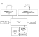
図1は、本出願の一実施形態に適用可能な通信システムの可能なアーキテクチャの概略図である。図1に示すように、通信システムは、LTEコアネットワークデバイス111、LTEアクセスネットワークデバイス121、NRアクセスネットワークデバイス122、および端末デバイス131を少なくとも含む。通信システムのアーキテクチャは、5G NSAネットワークアーキテクチャであり得る。5G NSAネットワークアーキテクチャには、4G無線アクセスネットワークおよび5G NRデュアルコネクション(EUTRA-NR Dual Connection、EN-DC)アーキテクチャがある。LTEアクセスネットワークデバイス121は、LTEネットワークをサポートするデバイスであり、NRアクセスネットワークデバイス122は、NRネットワークをサポートするデバイスであり、端末デバイス131は、LTEネットワークとNRネットワークの両方をサポートするデバイスである。LTEアクセスネットワークデバイス121はマスタノードであってもよく、これは、EN-DCにおいてマスタeNodeB(MeNB)と呼ばれ、NRアクセスネットワークデバイス122はセカンダリノードであってもよく、これはEN-DCにおいてセカンダリgNodeB(SgNB)と呼ばれる。LTEアクセスネットワークデバイス121およびNRアクセスネットワークデバイス122は、X2インターフェースを使用して通信接続されている。LTEアクセスネットワークデバイス121は、S1-Uインターフェースを使用することによってLTEコアネットワークデバイス111と通信接続することができる。NRアクセスネットワークデバイス122もまた、S1-Uインターフェースを使用してLTEコアネットワークデバイス111と通信接続することができる。
FIG. 1 is a schematic diagram of a possible architecture of a communication system applicable to an embodiment of the present application. As shown in FIG. 1, the communication system includes at least an LTE
任意選択で、通信システムは端末デバイス132をさらに含んでもよい。端末デバイス132は、LTEアクセスネットワークデバイス121と通信接続しており、端末デバイス132は、LTEネットワークのみをサポートするデバイスである。図1は単なる概略図である。通信システムは、他のネットワークデバイスをさらに含んでもよく、例えば、図1には描かれていない、無線中継デバイスおよび無線バックホールデバイスをさらに含んでもよい。本出願のこの実施形態は、通信システムに含まれるコアネットワークデバイスの数、アクセスネットワークデバイスの数、および端末デバイスの数に制限を課さない。例えば、端末デバイス131は、1つまたは複数のアクセスネットワークデバイスとさらに通信接続していてもよい。
Optionally, the communication system may further include a
EN-DCネットワークアーキテクチャにおけるデバイス間の通信接続は、無線方式または有線方式で実施されてよい。コアネットワークデバイスおよびアクセスネットワークデバイスは、別々の異なる物理的デバイスであってもよい、またはコアネットワークデバイスの機能およびアクセスネットワークデバイスの論理機能は、同じ物理的デバイスに統合されてもよい、またはコアネットワークデバイスのいくつかの機能およびアクセスネットワークデバイスのいくつかの機能は、1つの物理的デバイスに統合されてもよい。 Communication connections between devices in the EN-DC network architecture may be implemented in a wireless or wired manner. The core network device and the access network device may be separate and different physical devices, or the functionality of the core network device and the logical functionality of the access network device may be integrated into the same physical device, or the core network device Some functions of the device and some functions of the access network device may be integrated into one physical device.
本出願におけるアクセスネットワークデバイスは、LTEにおける進化型ノードB(NodeB、eNBまたはe-NodeB)、NRにおける基地局(gNodeBまたはgNB)または送受信ポイント/送信受理ポイント(transmission receiving point/transmission reception point、TRP)、その後に進化した基地局、Wi-Fiシステムにおけるアクセスノード、無線中継ノード、無線バックホールノードなどを含むがこれらに限定されない、無線トランシーバ機能を有する任意のデバイスであり得る。基地局は、マクロ基地局、マイクロ基地局、ピコセル基地局、スモールセル、中継局、バルーンステーションなどであってもよい。基地局は、1つまたは複数のコサイトTRPまたは非コサイトTRPを含み得る。 The access network device in this application is an evolved NodeB (NodeB, eNB or e-NodeB) in LTE, a base station (gNodeB or gNB) in NR or a transmission receiving point/transmission reception point (TRP). ), subsequently evolved base stations, access nodes in Wi-Fi systems, wireless relay nodes, wireless backhaul nodes, etc., may be any device with wireless transceiver functionality. The base station may be a macro base station, micro base station, pico cell base station, small cell, relay station, balloon station, etc. A base station may include one or more cosite TRPs or non-cosite TRPs.
本出願の端末デバイスは、無線トランシーバ機能を有するデバイスであり、屋内または屋外、手持ち式、ウェアラブル、または車載を含む陸上に配備されてもよく、水上(例えば、船舶上)に配備されてもよく、あるいは空中(例えば、飛行機、バルーン、または衛星において)に配備されてもよい。端末デバイスは、携帯電話(mobile phone)、パッド(Pad)、無線トランシーバ機能を有するコンピュータ、仮想現実(virtual reality、VR)端末デバイス、拡張現実(augmented reality、AR)端末デバイス、産業用制御(industrial control)の無線端末、車載端末デバイス、自動運転(self driving)の無線端末、遠隔医療(remote medical)の無線端末、スマートグリッド(smart grid)の無線端末、交通安全(transportation safety)の無線端末、スマートシティ(smart city)の無線端末、スマートホーム(smart home)の無線端末、ウェアラブル端末デバイスなどであり得る。本出願のこの実施形態は、適用シナリオに制限を課さない。端末デバイスは、端末、ユーザ機器(user equipment、UE)、アクセス端末デバイス、車載端末、産業制御端末、UEユニット、UEステーション、移動局、モバイルコンソール、リモートステーション、リモート端末デバイス、モバイルデバイス、UE端末デバイス、端末デバイス、無線通信デバイス、UEプロキシ、UE装置などと呼ばれることもある。端末デバイスは、あるいは、固定式または移動式であってもよい。 The terminal device of the present application is a device with wireless transceiver functionality, and may be deployed on land, including indoors or outdoors, handheld, wearable, or vehicle-mounted, or may be deployed on water (e.g., on a ship). , or may be deployed in the air (eg, in an airplane, balloon, or satellite). Terminal devices include mobile phones, pads, computers with wireless transceiver functions, virtual reality (VR) terminal devices, augmented reality (AR) terminal devices, and industrial control devices. control) wireless terminals, in-vehicle terminal devices, self-driving wireless terminals, remote medical wireless terminals, smart grid wireless terminals, transportation safety wireless terminals, It can be a smart city wireless terminal, a smart home wireless terminal, a wearable terminal device, etc. This embodiment of the present application does not impose any restrictions on application scenarios. Terminal devices include terminals, user equipment (UE), access terminal devices, in-vehicle terminals, industrial control terminals, UE units, UE stations, mobile stations, mobile consoles, remote stations, remote terminal devices, mobile devices, and UE terminals. Also referred to as a device, terminal device, wireless communication device, UE proxy, UE equipment, etc. A terminal device may alternatively be fixed or mobile.
加えて、端末デバイスは、あるいは、モノのインターネット(internet of things、IoT)システム内の端末デバイスであってもよい。IoTは、将来の情報技術の発展の重要な部分である。IoTの主な技術的特徴は、人間と機械の相互接続およびすべての相互接続のインテリジェントネットワークを実現するために、対象物が通信技術を使用してネットワークに接続されることである。本出願のこの実施形態における端末デバイスは、代替的として、マシンタイプ通信(machine type communication、MTC)における端末デバイスであってもよい。あるいは、本出願の端末デバイスは、1つまたは複数の構成要素またはユニットとして車両に組み込まれた車載モジュール、車載構成要素、車載チップ、または車載ユニットであってもよく、車両は、組み込まれた車載モジュール、車載構成要素、車載チップ、または車載ユニットを使用することによって本出願の方法を実施してもよい。したがって、本出願の本実施形態は、車両のインターネット、例えば、車両とすべてのもの(vehicle to everything、V2X)、ロングタームエボリューション車両(long term evolution-vehicle、LTE-V)、および車車間(vehicle-to-vehicle、V2V)に適用されてよい。 Additionally, the terminal device may alternatively be a terminal device in an internet of things (IoT) system. IoT is an important part of future information technology development. The main technical feature of IoT is that objects are connected to the network using communication technology to realize the interconnection of humans and machines and the intelligent network of all interconnections. The terminal device in this embodiment of the present application may alternatively be a terminal device in machine type communication (MTC). Alternatively, the terminal device of the present application may be an in-vehicle module, an in-vehicle component, an in-vehicle chip, or an in-vehicle unit incorporated into a vehicle as one or more components or units, where the vehicle The methods of the present application may be implemented by using modules, vehicle components, vehicle chips, or vehicle units. Accordingly, the present embodiments of the present application are applicable to the Internet of Vehicles, such as vehicle-to-everything (V2X), long term evolution-vehicle (LTE-V), and vehicle-to-vehicle (V2X). -to-vehicle, V2V).
図2は、本出願による端末デバイス200の概略構造図である。端末デバイス200は、図1に示す端末デバイス131または端末デバイス132に対応してもよい。端末デバイス200は、プロセッサ210、アンテナ1、アンテナ2、移動通信モジュール220、無線通信モジュール230、メモリ240、充電管理モジュール250、電力管理モジュール251、バッテリ252、およびディスプレイ260を含み得る。
FIG. 2 is a schematic structural diagram of a
本出願のこの実施形態で示される構造は、端末デバイス200に対して特定の限定を構成しないことが理解され得る。本出願のいくつかの他の実施形態では、端末デバイス200は、図に示されるものより多い、または少ない構成要素を含む場合がある、あるいはいくつかの構成要素が組み合わされる、またはいくつかの構成要素が分割される、もしくは異なる構成要素構成が使用される。図示された構成要素は、ハードウェア、ソフトウェア、またはソフトウェアとハードウェアの組み合わせによって実装されてもよい。
It can be understood that the structure shown in this embodiment of the present application does not constitute any particular limitation to the
プロセッサ210は1つまたは複数の処理ユニットを含み得る。例えば、プロセッサ210は、アプリケーションプロセッサ(application processor、AP)、モデムプロセッサ、グラフィックス処理ユニット(graphics processing unit、GPU)、画像信号プロセッサ(image signal processor、ISP)、コントローラ、メモリ、ビデオコーデック、デジタル信号プロセッサ(digital signal processor、DSP)、ベースバンドプロセッサ、および/またはニューラルネットワーク処理ユニット(neural network processing unit、NPU)を含むことができる。異なる処理ユニットは、独立したデバイスであってもよく、または1つまたは複数のプロセッサに統合されてもよい。
コントローラは、端末デバイス200の中枢センタおよびコマンドセンタであってもよい。コントローラは、命令取得および命令実行を制御するために、命令演算コードおよび時系列信号に基づいて動作制御信号を生成することができる。
The controller may be the central and command center of the
メモリが、命令およびデータを記憶するために、プロセッサ210内にさらに配置されてよい。いくつかの実施形態では、プロセッサ210内のメモリは、キャッシュメモリである。メモリは、プロセッサ210によって使用されたばかりか、または周期的に使用された命令またはデータを記憶することができる。プロセッサ210が命令またはデータを再び使用する必要がある場合、命令またはデータはメモリから直接呼び出されてもよい。反復されるアクセスが回避され、プロセッサ210の待ち時間が短縮され、それによってシステム効率が改善される。
Memory may further be located within
一部の実施形態では、プロセッサ210は、1つまたは複数のインターフェースを含むことができる。インターフェースは、集積回路間(inter-integrated circuit、I2C)インターフェース、集積回路間サウンド(inter-integrated circuit sound、I2S)インターフェース、パルス符号変調(pulse code modulation、PCM)インターフェース、汎用非同期受信機/送信機(universal asynchronous receiver/transmitter、UART)インターフェース、モバイル産業プロセッサインターフェース(mobile industry processor interface、MIPI)インターフェース、汎用入力/出力(general-purpose input/output、GPIO)インターフェース、加入者識別モジュール(subscriber identity module、SIM)インターフェース、ユニバーサルシリアルバス(universal serial bus、USB)インターフェースなどを含むことができる。
In some embodiments,
アンテナ1およびアンテナ2は、電磁波信号を送受信するように構成されている。端末デバイス200の各アンテナは、単一または複数の通信帯域をカバーするように構成されてもよい。アンテナ利用率を改善するために、異なるアンテナが多重化されてもよい。例えば、アンテナ1は、無線ローカルエリアネットワークのダイバーシティアンテナに多重化されてもよい。いくつかの他の実施形態において、アンテナは、チューニングスイッチと組み合わせて使用されてもよい。
端末デバイス200は、外部デバイスと通信するように構成された通信モジュールを含み得る。例えば、通信モジュールは、移動通信モジュール220および無線通信モジュール230を含むことができる。
移動通信モジュール220は、2G/3G/4G/5Gを含む、端末デバイス200に適用される無線通信ソリューションを提供することができる。移動通信モジュール220は、少なくとも1つのフィルタ、スイッチ、電力増幅器、低雑音増幅器(low noise amplifier、LNA)などを含むことができる。移動通信モジュール220は、アンテナ1から電磁波を受信し、受信した電磁波に対してフィルタリングおよび増幅などの処理を行い、処理された電磁波を復調のためにモデムプロセッサに送信することができる。移動通信モジュール220は、モデムプロセッサによって変調された信号をさらに増幅し、信号を電磁波に変換し、アンテナ1を使用して電磁波を放射することができる。いくつかの実施形態では、移動通信モジュール220の少なくともいくつかの機能モジュールは、プロセッサ210内に配置されてもよい。いくつかの実施形態では、移動通信モジュール220の少なくともいくつかの機能モジュールおよびプロセッサ210の少なくともいくつかのモジュールは同じデバイスに配置され得る。
The
無線通信モジュール230は、端末デバイス200に適用され、無線ローカルエリアネットワーク(wireless local area networks、WLAN)(ワイヤレスフィデリティ(wireless-fidelity、Wi-Fi)ネットワークなど)、ブルートゥース(登録商標)(bluetooth、BT)、全地球航法衛星システム(global navigation satellite system、GNSS)、周波数変調(frequency modulation、FM)、近距離無線通信(near field communication、NFC)、および赤外線(infrared、IR)を含む、無線通信ソリューションを提供し得る。無線通信モジュール230は、少なくとも1つの通信処理モジュールを統合する1つまたは複数のデバイスであってよい。無線通信モジュール230は、アンテナ2を使用して電磁波を受信し、電磁波信号を変調およびフィルタリングし、処理された信号をプロセッサ210に送信する。無線通信モジュール230は、送信されるべき信号をプロセッサ210からさらに受信し、信号に対して周波数変調および増幅を行い、信号を電磁波に変換し、アンテナ2を使用することによって電磁波を放射することができる。
The wireless communication module 230 is applied to the
いくつかの実施形態では、端末デバイス200のアンテナ1は移動通信モジュール220に結合され、アンテナ2は無線通信モジュール230に結合され、その結果端末デバイス200は、無線通信技術を使用することによってネットワークおよび別のデバイスと通信してもよい。無線通信技術は、移動通信用グローバルシステム(global system for mobile communications、GSM)、汎用パケット無線サービス(general packet radio service、GPRS)、符号分割多元接続(code division multiple access、CDMA)、広帯域符号分割多元接続(wideband code division multiple access、WCDMA(登録商標))、時分割符号分割多元接続(time-division code division multiple access、TD-SCDMA)、ロングタームエボリューション(long term evolution、LTE)、BT、GNSS、WLAN、NFC、FM、IR技術などを含むことができる。GNSSは、全地球測位システム(global positioning system、GPS)、全地球航法衛星システム(global navigation satellite system、GLONASS)、Beidou航法衛星システム(beidou navigation satellite system、BDS)、準天頂衛星システム(quasi-zenith satellite system、QZSS)、および/または衛星ベース増強システム(satellite based augmentation system、SBAS)を含むことができる。
In some embodiments,
メモリ240は、コンピュータ実行可能プログラムコードを記憶するように構成され、実行可能プログラムコードは命令を含む。プロセッサ210は、メモリ240に記憶された命令を実行することにより、端末デバイス200の様々な機能アプリケーションおよびデータ処理を実行する。メモリ240は、プログラム記憶領域およびデータ記憶領域を含み得る。プログラム記憶領域は、オペレーティングシステム、少なくとも1つの機能(例えば、音声再生機能または画像再生機能)に必要なアプリケーションプログラムなどを記憶することができる。データ記憶領域は、端末デバイス200の使用中に作成されたデータ(音声データや電話帳など)を記憶することができる。また、メモリ240は、高速ランダムアクセスメモリを含んでもよく、少なくとも1つの磁気ディスク記憶装置、フラッシュメモリデバイス、またはユニバーサルフラッシュストレージ(universal flash storage、UFS)などの不揮発性メモリをさらに含んでもよい。
Memory 240 is configured to store computer executable program code, the executable program code including instructions.
充電管理モジュール250は、充電器から充電入力を受け取るように構成される。充電器は、無線充電器であり得るか、または有線充電器であり得る。いくつかの有線充電実施形態では、充電管理モジュール250は、USBインターフェースを使用することによって有線充電器から充電入力を受け取ることができる。いくつかの無線充電実施形態では、充電管理モジュール250は、端末デバイス200の無線充電コイルを使用して無線充電入力を受信することができる。バッテリ252を充電することに加えて、充電管理モジュール250は、電力管理モジュール251を使用して端末デバイスに電力をさらに供給してもよい。
電力管理モジュール251は、バッテリ252、充電管理モジュール250、およびプロセッサ210を接続するように構成される。電力管理モジュール251は、バッテリ252および/または充電管理モジュール250の入力を受信し、プロセッサ210、メモリ240、ディスプレイ260、移動通信モジュール220、無線通信モジュール230などに電力を供給する。電力管理モジュール251は、バッテリ容量、バッテリサイクル数、およびバッテリの健全性状況(漏れまたはインピーダンス)などのパラメータを監視するようにさらに構成され得る。いくつかの他の実施形態では、電力管理モジュール251は、あるいは、プロセッサ210内に配置されていてもよい。一部の他の実施形態では、電力管理モジュール251および充電管理モジュール250は、あるいは、同じデバイス内に配置されてもよい。
端末デバイス200は、GPU、ディスプレイ260、アプリケーションプロセッサなどを用いて表示機能を実現する。GPUは、画像処理用のマイクロプロセッサであり、ディスプレイ260およびアプリケーションプロセッサに接続されている。GPUは、グラフィックスをレンダリングするために数学的および幾何学的計算を実行するように構成される。プロセッサ210は、プログラム命令を実行して表示情報を生成または変更する1つまたは複数のGPUを含むことができる。
The
ディスプレイ260は、画像、ビデオなどを表示する。ディスプレイ260は、表示パネルを有する。表示パネルは、液晶ディスプレイ(liquid crystal display,LCD)、有機発光ダイオード(organic light-emitting diode,OLED)、アクティブマトリックス有機発光ダイオード(active-matrix organic light emitting diode,AMOLED)、フレキシブル発光ダイオード(flex light-emitting diode,FLED)、Miniled、MicroLed、Micro-oLed、量子ドット発光ダイオード(quantum dot light emitting diodes,QLED)などであってもよい。一部の実施形態では、端末デバイス200は、1つまたはN個のディスプレイ260を含んでもよく、Nは、1より大きい正の整数である。
図3は、本出願による端末デバイス200のインターフェースプロトコルの階層通信の概略図である。図3に示すように、端末デバイス200は、図1に示す端末デバイス131または端末デバイス132に対応してもよい。端末デバイス200は、L1物理レイヤ(物理レイヤ、PHY)、L2データリンクレイヤ、およびL3ネットワークレイヤを含み得る。
FIG. 3 is a schematic diagram of the layered communication of the interface protocol of the
L1物理レイヤ(PHY)は最下層に位置し、変調および復調、アンテナマッピング、または他の通信物理レイヤ機能を行うことを主に担当する。 The L1 physical layer (PHY) is located at the lowest layer and is primarily responsible for performing modulation and demodulation, antenna mapping, or other communication physical layer functions.
L2データリンクレイヤは、パケットデータコンバージェンスプロトコル(packet data convergence protocol、PDCP)レイヤ、無線リンク制御(radio link control、RLC)レイヤ、および媒体アクセス制御(medium access control、MAC)レイヤを含む。PDCPレイヤは、無線インターフェースによって伝送されるビットトラフィックを低減するために、パケットヘッダ圧縮を行うことを主に担当する。RLCレイヤは、主に、セグメント化および接続などの処理、ならびに上位層データのシーケンス制御を担当する。MACレイヤは、主に、ハイブリッド自動再送要求(hybrid automatic repeat request、HARQ)再伝送、アップリンクおよびダウンリンクスケジューリングなどを担当する。 The L2 data link layer includes a packet data convergence protocol (PDCP) layer, a radio link control (RLC) layer, and a medium access control (MAC) layer. The PDCP layer is mainly responsible for performing packet header compression to reduce the bit traffic transmitted by the air interface. The RLC layer is mainly responsible for processing such as segmentation and connection, as well as sequence control of upper layer data. The MAC layer is mainly responsible for hybrid automatic repeat request (HARQ) retransmission, uplink and downlink scheduling, etc.
L3ネットワークレイヤは、非アクセス層(non-access stratum、NAS)レイヤおよび無線リソース制御(radio resource control、RRC)レイヤを含む。NASは、4G/5G通信リンクまたはサービスを確立または解放するために使用される情報、およびモビリティ管理情報などのユーザ情報または制御情報を送信するために使用され得る。NASレイヤの下のプロトコルレイヤはまた、アクセス層(access stratum、AS)と呼ばれる場合もある。RRCレイヤは、端末デバイスとアクセスネットワークデバイスとの間の複数の機能のためのシグナリングプロトコルをサポートし、NASレイヤおよびASレイヤのシステムメッセージをブロードキャストし、RRC接続を確立し、維持し、解放し、エンドツーエンド無線接続を確立し、修正し、解放し、端末デバイスの測定報告、セルハンドオーバ、およびセル再選択などのモビリティ管理機能を行う。実際の用途では、端末デバイスは、4Gおよび5Gアクセスネットワークの確立および解放などの動作を実施するために、L3ネットワークレイヤを使用することによってネットワーク側と通信することができる。詳細は、本出願において後述する。 The L3 network layer includes a non-access stratum (NAS) layer and a radio resource control (RRC) layer. The NAS may be used to transmit user information or control information, such as information used to establish or release 4G/5G communication links or services, and mobility management information. The protocol layer below the NAS layer is also sometimes called the access stratum (AS). The RRC layer supports signaling protocols for multiple functions between terminal devices and access network devices, broadcasts system messages in the NAS layer and AS layer, establishes, maintains, and releases RRC connections, Establishes, modifies, and releases end-to-end radio connections and performs mobility management functions such as end device measurement reporting, cell handover, and cell reselection. In practical applications, terminal devices can communicate with the network side by using the L3 network layer to perform operations such as establishing and releasing 4G and 5G access networks. Details will be described later in this application.
EN-DCのネットワークアーキテクチャでは、端末デバイスのために構成されたセルグループ(cell group)は2つのグループ(group)に分割され、一方のグループはMeNBによってカバーされるセルを含み、他方のグループはSgNBによってカバーされるセルを含む。MeNBによってカバーされるセルを含むグループは、マスタセルグループ(master cell group、MCG)と呼ばれ、SgNBによってカバーされるセルを含むグループは、セカンダリセルグループ(secondary cell group、SCG)と呼ばれる。例えば、図1に示すように、LTEアクセスネットワークデバイス121によってカバーされるセルを含むグループはMCGと呼ばれ、NRアクセスネットワークデバイス122によってカバーされるセルを含むグループはSCGと呼ばれる。
In the network architecture of EN-DC, the cell group configured for the terminal device is divided into two groups, one group contains the cells covered by the MeNB, and the other group contains the cells covered by the MeNB. Contains cells covered by SgNB. A group including cells covered by a MeNB is called a master cell group (MCG), and a group including cells covered by an SgNB is called a secondary cell group (SCG). For example, as shown in FIG. 1, the group containing cells covered by LTE
1つのcell groupにおいて、無線ベアラの無線リンク制御(radio link control、RLC)構成および論理チャネル構成は、RLCベアラと呼ばれる。RLCベアラのうち、MCG上にのみ構成される無線ベアラは、MCGベアラと呼ばれる。RLCベアラのうち、SCG上にのみ構成される無線ベアラは、SCGベアラと呼ばれる。RLCベアラのうち、MCGとSCGの両方に設定される無線ベアラは、スプリット(split)ベアラと呼ばれる。MeNBにおけるパケットデータコンバージェンスプロトコル(packet data convergence protocol、PDCP)の無線ベアラは、マスタノード(master node、MN)によって終端されるベアラと称される。SgNBにおけるPDCPの無線ベアラは、セカンダリノード(secondary node、SN)の無線ベアラと呼ばれる。 In one cell group, the radio link control (RLC) configuration and logical channel configuration of a radio bearer is called an RLC bearer. Among RLC bearers, radio bearers configured only on MCG are called MCG bearers. Among RLC bearers, radio bearers configured only on SCG are called SCG bearers. Among RLC bearers, a radio bearer configured for both MCG and SCG is called a split bearer. A packet data convergence protocol (PDCP) radio bearer in MeNB is called a bearer terminated by a master node (MN). The PDCP radio bearer in SgNB is called a secondary node (SN) radio bearer.
図4は、EN-DCのネットワークアーキテクチャにおいて端末デバイスによって認識され得るベアラを示し、端末デバイスは、図1に示す端末デバイス131に対応し得る。ベアラは、MCGベアラ、SCGベアラ、およびSplitベアラを含む。MCGベアラは、データがコアネットワークデバイスからMeNBに伝送され、MeNBによって端末デバイスに直接転送されることを意味する。SCGベアラは、データがコアネットワークデバイスからSeNBに伝送され、SeNBによって端末デバイスに直接転送されることを意味する。Splitベアラは、サービスを提供するために、基地局側でデータが分割され、MeNBもしくはSeNBによって端末デバイスに転送され得ること、またはMeNBとSeNBの両方によって事前設定された分割比に基づいて端末デバイスにデータが伝送されることを意味する。データベアラがMCGベアラであることを端末デバイスが認識するとき、データ通信のために使用される通信リンク(MCGリンクとも呼ばれる)は、LTE PDCP-LTE RLC-LTE MACである。端末デバイスが、データベアラがSCGベアラであると認識するとき、データ通信のために使用される通信リンク(SCGリンクとも呼ばれる)は、NR PDCP-NR RLC-NR MACである。データベアラがSplitベアラであることを端末デバイスが認識するとき、データ通信のために使用される通信リンク(Splitリンクとも呼ばれる)は、LTE PDCP-LTE RLC-LTE MACまたはNR PDCP-NR RLC-NR MACである。SCGリンクは5G NRのネットワークリソースのみを使用することから、SCGリンクはNRリンクと呼ばれることもある。MCGリンクは4G LTEのネットワークリソースを使用することから、MCGリンクはLTEリンクと呼ばれることもある。
FIG. 4 shows bearers that may be recognized by a terminal device in the EN-DC network architecture, which may correspond to the
図5は、EN-DCのネットワークアーキテクチャにおいてネットワーク側によって認識され得るベアラを示し、MeNBは図1に示すアクセスネットワークデバイス131に対応してよく、SgNBは図1に示すアクセスネットワークデバイス132に対応してよい。ベアラは、MNによって終端されるMCGベアラ、MNによって終端されるSCGベアラ、MNによって終端されるSplitベアラ、SNによって終端されるMCGベアラ、SNによって終端されるSCGベアラ、およびSNによって終端されるSplitベアラを含む。MNによって終端されるベアラは、SeNB以外のMeNBがPDCPレイヤとする無線ベアラを指す。反対に、SNによって終端されるベアラは、そのPDCPレイヤがMeNBではなくSeNBにある無線ベアラを指す。ネットワーク側によって認識されるデータベアラがMNによって終端されたMCGベアラである場合、データ通信中の通信リンクはLTE PDCP-LTE RLC-LTE MACである。ネットワーク側によって認識されるデータベアラがMNによって終端されるSplitベアラである場合、データ通信中の通信リンクはLTE PDCP-LTE RLC-LTE MACまたはLTE PDCP-NR RLC-NR MACである。具体的な選択は、実際の要件に基づいて行われてよく、限定されない。ネットワーク側によって認識される様々なデータベアラに対応する通信リンクについて、詳細が図に示されている。ここでは詳細は繰り返されない。
FIG. 5 shows the bearers that can be recognized by the network side in the network architecture of EN-DC, where the MeNB may correspond to the
理解を容易にするために、本出願では、図2に示す構造を有する端末デバイスを一例として使用し、本出願の本実施形態で提供される通信方法を、添付の図面および適用シナリオを参照して詳細に説明する。 For ease of understanding, this application uses a terminal device with the structure shown in FIG. 2 as an example, and the communication method provided in this embodiment of the application is described with reference to the accompanying drawings and application scenarios. This will be explained in detail.
例えば、図1に示す通信システムでは、データ伝送速度を向上させるために、端末デバイス131は、LTEアクセスネットワークデバイス121およびNRアクセスネットワークデバイス122を使用することによって、LTEコアネットワークデバイス111とのデータ伝送を実行することができる。端末デバイス132がLTEアクセスネットワークデバイス121のみを使用することによってLTEコアネットワークデバイス111とのデータ伝送を実行する方式と比較して、端末デバイス131の電力消費は高くなる。
For example, in the communication system shown in FIG. 1, in order to increase data transmission speed,
これに基づいて、本出願の一実施形態は通信方法を提供する。端末デバイス131がLTEアクセスネットワークデバイス121とNRアクセスネットワークデバイス122の両方と通信接続している通信システムでは、端末デバイス131は、端末デバイス131が省電力モードにあるかどうか、および/または端末デバイス131の電力消費が第1の事前設定値未満であるかどうか、および/または端末デバイス131の背面カバーの温度が第2の事前設定値以上であるかどうかに基づいてNRリンクを解放するかどうかを判定する。NRリンクが解放された後、端末デバイス131の電力消費が低減され、それによってユーザエクスペリエンスが向上する。
Based on this, one embodiment of the present application provides a communication method. In a communication system where the
本出願のこの実施形態の理解を容易にするために、本出願のこの実施形態が説明される前に以下の説明が提供される。 To facilitate understanding of this embodiment of the present application, the following explanation is provided before this embodiment of the present application is described.
第1に、本出願のこの実施形態では、「指示」は、直接的な指示および間接的な指示を含んでよい、または明示的な指示および暗黙的な指示を含んでもよい。 First, in this embodiment of the present application, "instructions" may include direct and indirect instructions, or may include explicit and implicit instructions.
第2に、以下に示す実施形態では、「第1の」、「第2の」、および様々な数値は、便宜上区別するために記載されているにすぎず、本出願の実施形態の範囲を限定するために使用されるものではない。例えば、数値は、異なる指示情報を区別するために使用される。 Second, in the embodiments shown below, "first", "second", and various numerical values are only mentioned for convenience and distinction, and do not limit the scope of the embodiments of the present application. It is not intended to be used as a limitation. For example, numerical values are used to distinguish between different instructional information.
第3に、本出願の本実施形態における「LTE」は4Gを指しうる。例えば、「LTEネットワーク」は、「4Gネットワーク」を指してよい。別の例では、「LTEリンク」は、「4Gリンク」を指す場合がある。別の例では、「LTEアクセスネットワークデバイス」は、「4Gアクセスネットワークデバイス」を指す場合がある。 Third, "LTE" in this embodiment of the present application may refer to 4G. For example, an "LTE network" may refer to a "4G network." In another example, "LTE link" may refer to "4G link." In another example, "LTE access network device" may refer to "4G access network device."
第4に、本出願の本実施形態における「NR」は、5Gを指しうる。例えば、「NRネットワーク」は、「5Gネットワーク」を指してよく、別の例では、「NRリンク」は、「5Gリンク」を指す場合があり、別の例では、「NRアクセスネットワークデバイス」は「5Gアクセスネットワークデバイス」を指す場合がある。 Fourth, "NR" in this embodiment of the present application may refer to 5G. For example, "NR network" may refer to "5G network," in another example, "NR link" may refer to "5G link," and in another example, "NR access network device" May refer to "5G access network device".
第5に、本出願のこの実施形態における「NRリンク」は、端末デバイスとNRアクセスネットワークデバイスとの間のリンク、NRアクセスネットワークデバイスとLTEコアネットワークデバイスとの間のリンク、端末デバイスとLTEアクセスネットワークデバイスとの間のリンク、またはLTEアクセスネットワークデバイスとLTEコアネットワークデバイスとの間のリンクを指す。 Fifth, "NR link" in this embodiment of the present application refers to the link between the terminal device and the NR access network device, the link between the NR access network device and the LTE core network device, the link between the terminal device and the LTE access Refers to the link between a network device or between an LTE access network device and an LTE core network device.
第6に、本出願のこの実施形態における「LTEリンク」は、端末デバイスとLTEアクセスネットワークデバイスとの間のリンク、またはLTEアクセスネットワークデバイスとLTEコアネットワークデバイスとの間のリンクを指す。 Sixth, "LTE link" in this embodiment of the present application refers to a link between a terminal device and an LTE access network device, or a link between an LTE access network device and an LTE core network device.
以下で、添付の図面を参照して、本出願の実施形態で提供される通信方法を説明する。 In the following, communication methods provided in embodiments of the present application will be described with reference to the accompanying drawings.
図6A~図6Bから図10は、以下のプロセスを詳細に説明しており、すなわち端末デバイス131がLTEアクセスネットワークデバイス121およびNRアクセスネットワークデバイス122の両方と通信接続している通信システムでは、端末デバイス131は、端末デバイス131が省電力モードにあるとき、および/または端末デバイス131の電力消費が第1の事前設定値未満であるとき、および/または端末デバイス131の背面カバーの温度が第2の事前設定値以上であるときにNRリンクを解放する。
6A to 6B to FIG. 10 describe in detail the following process, namely, in a communication system where a
図6A~図6Bは、本出願の一実施形態による通信方法300の概略フローチャートである。
6A-6B are a schematic flowchart of a
ステップ310:端末デバイス131は、EN-DCネットワークに登録する。
Step 310: The
端末デバイス131がEN-DCネットワークに登録することは、端末デバイス131とLTEアクセスネットワークデバイス121との間のLTEリンクの確立、および端末デバイス131とNRアクセスネットワークデバイス122との間のNRリンクの確立として理解され得る。端末デバイス131は、電源投入後にLTEリンクおよびNRリンクの確立を直接完了することができる、または端末デバイス131は、電源投入後にLTEリンクの確立を完了し、次いでNRリンクの確立を完了する場合もある。端末デバイス131は、電源投入後の任意の時点でLTEリンクおよびNRリンクの確立を完了することができ、これは本出願では限定されない。
Registering the
端末デバイス131がEN-DCネットワークに登録した後、端末デバイス131はEN-DCネットワークにキャンプオンし、EN-DCネットワークはLTEリンクおよびNRリンクを含む。端末デバイス131は、ユーザの動作を検出し、次いで、ユーザのサービス要求を実施するために、ユーザによって要求されるサービスの関連データを伝送することができる。
After the
EN-DCネットワークでは、端末デバイス131はLTEリンクを使用してシグナリング伝送を実施し、端末デバイス131はNRリンクを使用してデータ伝送を実施する。例えば、端末デバイス131がEN-DCネットワークに登録することは、ステップaからステップfを含むことができる。
In the EN-DC network, the
ステップa:端末デバイス131は、端末デバイス131のNASレイヤを使用することによってLTEアクセスネットワークデバイス121にアタッチ(attach)要求メッセージを送信し、アタッチ要求メッセージは、端末デバイス131の識別子およびNR能力を搬送し、アタッチ要求メッセージは、端末デバイス131の識別子に基づいてアタッチ動作を行うように要求するために使用される。
Step a: The
ステップb:LTEアクセスネットワークデバイス121は、ステップaで受信したアタッチ要求メッセージをLTEコアネットワークデバイス111に送信し、LTEコアネットワークデバイス111は、アタッチ要求メッセージに基づいて端末デバイス131に対してアタッチ動作を行い、アタッチ動作が完了した後で、LTEアクセスネットワークデバイス121にアタッチ受け入れ(attach accept)メッセージを送信し、アタッチ受け入れメッセージは、端末デバイス131に対するアタッチ動作が完了したことを指示するために使用される。あるいは、LTEコアネットワークデバイス111は、アタッチ要求メッセージに基づいて端末デバイス131に対してアタッチ動作を行わず、LTEアクセスネットワークデバイス121にアタッチ拒否(attach reject)メッセージを送信する場合があり、アタッチ拒否メッセージは、端末デバイス131に対してアタッチ動作が行われないことを示すために使用される。
Step b: LTE
ステップc:LTEアクセスネットワークデバイス121は、アタッチ受け入れメッセージまたはアタッチ拒否メッセージを端末デバイス131のRRCレイヤに送信する。
Step c: The LTE
端末デバイス131がアタッチ受け入れメッセージを受信した後で、すなわち、端末デバイス131がEN-DCネットワークに登録した後で、端末デバイス131はLTEリンクを使用することによってシグナリング伝送を行うことができ、すなわち、端末デバイスはLTEアクセスネットワークデバイス121とシグナリング伝送を行うことができ、端末デバイス131はNRリンクを使用することによってデータ伝送を行うことができ、すなわち、端末デバイス131はNRアクセスネットワークデバイス122とデータ伝送を行うことができる。
After the
端末デバイス131がEN-DCネットワークに登録した後で、端末デバイス131の5Gスイッチが有効状態にあるときには、モバイルネットワーク識別子「5G」が端末デバイス131の表示インターフェースに表示されてよく、端末デバイス131の表示インターフェースのドロップダウンステータスバーに提示される5Gスイッチも有効状態にされてよい。
After the
ステップ320:端末デバイス131は、端末デバイス131が第1の事前設定条件を満たすと判定する。
Step 320: The
第1の事前設定条件は、以下の、端末デバイス131の省電力モードが有効にされていること、端末デバイス131のバッテリ電力が第1の事前設定値以下であること、または端末デバイス131の背面カバーの温度が第2の事前設定値以上であることのうちの少なくとも1つを含む。
The first preset condition is that the power saving mode of the
端末デバイス131が省電力モードにあることは、端末デバイス131の省電力モードのスイッチが有効状態にあることとして理解され得る。端末デバイス131の省電力モードが有効状態にあることは、ユーザが端末デバイス131の省電力モードのスイッチをオンにすることであってよい、または、端末デバイス131の省電力モードが有効状態にあることは、端末デバイス131が端末デバイス131の省電力モードのスイッチをオンにすることであってもよい。
The
任意選択で、省電力モードは、超省電力モードをさらに含んでもよい。端末デバイス131が、端末デバイス131が省電力モードにあることを検出することは、端末デバイス131の省電力モードのスイッチが有効状態にあること、および/または端末デバイス131の超省電力モードのスイッチが有効状態にあることとして理解されてもよい、すなわち、端末デバイス131は、端末デバイス131の省電力モードのスイッチおよび超省電力モードのスイッチの少なくとも一方が有効状態にあることを端末デバイス131が検出した場合、端末デバイス131が省電力モードにあると見なす。
Optionally, the power saving mode may further include a super power saving mode. The
端末デバイス131の背面カバーにセンサが配置され、端末デバイス131のセンサが端末デバイス131の背面カバーの温度を検出してもよい。
A sensor may be disposed on the back cover of the
例えば、端末デバイス131は、以下の7つの場合に第1の事前設定条件が満たされたと判定することができる。
(1)端末デバイス131は、端末デバイス131が省電力モードにあることを検出する。
(2)端末デバイス131は、端末デバイス131のバッテリ電力が第1の事前設定値以下であることを検出する。
(3)端末デバイス131の背面カバーのセンサは、端末の背面カバーの温度が第2の事前設定値以上であることを検出する。
(4)端末デバイス131は、端末デバイス131が省電力モードにあることを検出し、端末デバイス131は、端末デバイス131のバッテリ電力が第1の事前設定値以下であることを検出する。
(5)端末デバイス131は、端末デバイス131が省電力モードにあることを検出し、端末デバイス131の背面カバーのセンサは、端末の背面カバーの温度が第2の事前設定値以上であることを検出する。
(6)端末デバイス131は、端末デバイス131のバッテリ電力が第1の事前設定値以下であることを検出し、端末デバイス131の背面カバーのセンサは、端末の背面カバーの温度が第2の事前設定値以上であることを検出する。
(7)端末デバイス131は、端末デバイス131が省電力モードにあることを検出し、端末デバイス131は、端末デバイス131のバッテリ電力が第1の事前設定値以下であることを検出し、端末デバイス131の背面カバーのセンサは、端末の背面カバーの温度が第2の事前設定値以上であることを検出する。
For example, the
(1)
(2) The
(3) The sensor on the back cover of the
(4) The
(5) The
(6) the
(7) The
端末デバイス131は、端末デバイス131が前述の7つのケースのうちの1つを満たしていることを端末デバイス131が検出した場合、端末デバイス131が第1の事前設定条件を満たしていると判定する。任意選択で、ステップ330において、端末デバイス131は5Gスイッチをオフにする。
The
端末デバイス131が5Gスイッチをオフにすることは、端末デバイス131の「設定」インターフェース上の5Gスイッチが無効状態にあることとして理解され得る。5Gスイッチがショートカットに追加されている場合、この場合、端末デバイス131の表示インターフェースのドロップダウンステータスバーに提示される「5G」ショートカットスイッチも無効状態にある。可能な設計では、端末デバイスが5G機能または5G能力を無効にするとき、端末デバイスの信号バーは、ネットワーク切断識別子、例えば「x」を表示し、端末デバイスが5G以外のネットワーク、例えば2G、3G、および4Gにキャンプオンすることをさらに表示し得る。
The
任意選択で、端末デバイス131が5Gスイッチをオフにすることは、端末デバイス131が5Gスイッチを能動的にオフにすること、および端末デバイス131が5Gスイッチを受動的にオフにすることであってもよい。端末デバイス131が5Gスイッチを能動的にオフにすることは、端末デバイス131が5Gスイッチをオフにすることとして理解され得る。端末デバイス131が5Gスイッチを受動的にオフにすることは、端末デバイス131が、5Gを無効にするユーザ動作を検出した後にのみ5Gスイッチをオフにすることとして理解され得る。
Optionally, the
任意選択で、端末デバイスはステップ330を行ってもよく、または端末デバイスはステップ330を行わなくてもよい。 Optionally, the terminal device may perform step 330, or the terminal device may not perform step 330.
端末デバイス131が5Gスイッチを受動的にオフにする場合、前述の方法は、ステップ331およびステップ332をさらに含む。
If the
ステップ331:端末デバイス131は、端末デバイス131の表示インターフェースに第1の選択ウィンドウを表示し、第1の選択ウィンドウは、第1の内容を表示し、第1の内容は、5Gを無効にするかどうかをリマインドするために使用される。
Step 331: The
第1の選択ウィンドウは、「有効化」ボタンまたは「OK」ボタンなどの機能ボタンと、「キャンセル」ボタンまたは「無効化」ボタンなどの機能ボタンとを含む。例えば、第1の選択ウィンドウを図7(a)、図7(b)、および図7(c)に示すことができる。図7(a)に示すように、端末デバイス131は、端末デバイス131が省電力モードにあることを検出してもよく、端末デバイス131は第1の選択ウィンドウを表示し、第1の選択ウィンドウは「有効化」ボタンおよび「キャンセル」ボタンを含む。図7(b)に示すように、端末デバイス131は、端末デバイス131が超省電力モードにあることを検出してもよく、端末デバイス131は第1の選択ウィンドウを表示し、第1の選択ウィンドウは「有効化」ボタンおよび「キャンセル」ボタンを含む。図7(c)に示すように、端末デバイス131は、端末デバイス131のバッテリ電力が20%であることを検出してもよく、端末デバイス131は第1の選択ウィンドウを表示し、第1の選択ウィンドウは「OK」ボタンおよび「無効化」ボタンを含む。
The first selection window includes functional buttons such as an "enable" or "ok" button, and a "cancel" or "disable" button. For example, the first selection window may be shown in FIG. 7(a), FIG. 7(b), and FIG. 7(c). As shown in FIG. 7(a), the
任意選択で、端末デバイス131が、端末デバイス131のバッテリ電力が第1の事前設定値以下であることを検出したときに、端末デバイス131が端末デバイス131の表示インターフェース上に第1の選択ウィンドウ(図7(a)または図7(b)に示されるような)を表示する前に、端末デバイス131は、端末デバイス131の表示インターフェース上に第2の選択ウィンドウをさらに表示することができ、第2の選択ウィンドウは第2の内容を表示し、第2の内容は、省電力モードを有効にするかどうかをリマインドするために使用される、または第2の選択ウィンドウは第2の内容を表示し、第2の内容は超省電力を有効にするかどうかをリマインドするために使用される。例えば、図7(d)に示すように、端末デバイス131は、端末デバイス131の電力が20%であることを検出してもよい。端末デバイス131が第1の選択ウィンドウ(第1の選択ウィンドウは、例えば図7(a)に示すように、省電力モードにおいて端末デバイス131によって表示される第1の選択ウィンドウである)を表示する前に、端末デバイス131は第2の選択ウィンドウを表示し、第2の選択ウィンドウに表示される第2の内容は、省電力モードを有効にするかどうかをリマインドするために使用され、第2の選択ウィンドウは、「キャンセル」ボタンおよび「有効化」ボタンを含む。別の例として、図7(e)に示すように、端末デバイス131は、端末デバイス131の電力が20%であることを検出してもよい。端末デバイス131が第1の選択ウィンドウ(第1の選択ウィンドウは、例えば図7(b)に示すように、超省電力モードにおいて端末デバイス131によって表示される第1の選択ウィンドウである)を表示する前に、端末デバイス131は第2の選択ウィンドウを表示し、第2の選択ウィンドウに表示される第2の内容は、超省電力を有効にするかどうかをリマインドするために使用され、第2の選択ウィンドウは、「キャンセル」ボタンおよび「有効化」ボタンを含む。
Optionally, when the
ステップ332:端末デバイス131が、ユーザが第1の選択ウィンドウ内の「有効化」ボタンまたは「OK」ボタンをタップしたことを検出した場合、端末デバイス131は5Gを無効にする。
Step 332: If the
5Gが無効にされた後、端末デバイスはNRリンクを解放することができる。NRリンクを解放することは、5Gスイッチをオフにすること(ステップ330)、5Gアクセスネットワークデバイス側で占有され、端末デバイスと5Gアクセスネットワークデバイスとの間の接続のために構成された無線リソースを解放すること、および端末デバイス側で占有され、端末デバイスと5Gアクセスネットワークデバイスとの間の接続のために構成された無線リソースを解放すること(ステップ340)を含む(ステップ350aからステップ359a)。 After 5G is disabled, the terminal device can release the NR link. Releasing the NR link means turning off the 5G switch (step 330), removing the radio resources occupied on the 5G access network device side and configured for the connection between the terminal device and the 5G access network device. and releasing radio resources occupied at the terminal device side and configured for the connection between the terminal device and the 5G access network device (step 340) (steps 350a to 359a).
端末デバイス131が5Gスイッチを能動的にオフにするとき、端末デバイス131は前述のステップ331からステップ332を行わず、端末デバイス131は5Gスイッチを直接オフにする、すなわち、端末デバイスが第1の事前設定条件を満たすとき、端末デバイスは、ユーザの確認動作および対話なしに5G機能を直接無効にする。
When the
具体的には、ステップ310からステップ330は、端末デバイス131のAPによって行われてもよい。
Specifically, steps 310 to 330 may be performed by the AP of the
ステップ340:端末デバイス131は、端末デバイス側で占有され、端末デバイス131とNRアクセスネットワークデバイス122との間の接続のために構成された無線リソースを解放する。
Step 340: The
端末デバイス131が、端末デバイス側で占有され、端末デバイス131とNRアクセスネットワークデバイス122との間の接続のために構成されている無線リソースを解放することは、端末デバイス131がNRリンクを解放することとして理解され得る。
The
具体的には、まず、端末デバイス131のAPは、端末デバイス131のNASレイヤにATコマンドを送信し、ATコマンドは、NRリンクを解放するように指示し、次に、端末デバイス131のNASは、NRリンクを解放するように端末デバイス131のRRCレイヤに指示し、最後に、端末デバイス131のRRCレイヤは、端末デバイス側で占有され、端末デバイス131とNRアクセスネットワークデバイス122との間の接続のために構成された無線リソースを解放する。
Specifically, first, the AP of the
任意選択で、端末デバイス131は、NRアクセスネットワークデバイス121側で占有され、端末デバイス131とNRアクセスネットワークデバイス122との間の接続のために構成された無線リソースを解放するように、NRリンクを解放するようにLTEアクセスネットワークデバイス122にさらに指示してもよい。すなわち、方法300は、ステップ350aからステップ359aをさらに含む。
Optionally, the
ステップ350a:端末デバイス131は、第1のデタッチ要求(detach request)メッセージをLTEアクセスネットワークデバイス121に送信する。第1のデタッチメッセージは、端末デバイス131の識別子を含み、第1のデタッチ要求メッセージは、NRリンクを解放するために、端末デバイス131の識別子に基づいてデタッチ動作を行うように要求するために使用される。これに対応して、LTEアクセスネットワークデバイス121は、端末デバイス131によって送信された第1のデタッチ要求メッセージを受信する。
Step 350a: The
具体的には、端末デバイス131のNASレイヤは、第1のデタッチ要求メッセージをLTEアクセスネットワークデバイス121に送信する。これに対応して、LTEアクセスネットワークデバイス121は、端末デバイス131のNASレイヤによって送信された第1のデタッチ要求メッセージを受信する。
Specifically, the NAS layer of the
現在、端末デバイス131とLTEアクセスネットワークデバイス121とは互いに通信接続していてよく、端末デバイス131とNRアクセスネットワークデバイス122も互いに通信接続していてよい。したがって、第1のデタッチ動作は、NRアクセスネットワークデバイス側で占有され、端末デバイスとNRアクセスネットワークデバイス122との間の接続のために構成された無線リソースを解放することとして理解され得る。すなわち、LTEアクセスネットワークデバイス121と端末デバイス131との間に確立されたベアラ、およびNRアクセスネットワークデバイス122と端末デバイス131との間に確立されたベアラが解放される。ベアラは、LTEアクセスネットワークデバイス121によって終端されるMCGベアラ、LTEアクセスネットワークデバイス121によって終端されるSCGベアラ、LTEアクセスネットワークデバイス121によって終端されるSplitベアラ、NRアクセスネットワークデバイス122によって終端されるMCGベアラ、NRアクセスネットワークデバイス122によって終端されるSCGベアラ、およびNRアクセスネットワークデバイス122によって終端されるSplitベアラであってもよい。
Currently, the
ステップ351a:LTEアクセスネットワークデバイス121は、第1のデタッチ要求メッセージをコアネットワークデバイス111に送信する。これに対応して、コアネットワークデバイス111は、LTEアクセスネットワークデバイス121によって送信された第1のデタッチ要求メッセージを受信する。
Step 351a: LTE
ステップ352a:コアネットワークデバイス111は、第1のデタッチメッセージに基づいて端末デバイス131に対してデタッチ動作を行う。
Step 352a: The
ステップ353a:LTEアクセスネットワークデバイス121は、コアネットワークデバイス111によって送信された第1のデタッチ受け入れ(detach accept)メッセージを受信し、第1のデタッチ受け入れメッセージは、端末デバイス131に対する第1のデタッチ要求が完了したことを示すために使用される。これに対応して、コアネットワークデバイス111は、LTEアクセスネットワークデバイス121に第1のデタッチ受け入れメッセージを送信する。
Step 353a: The LTE
ステップ354a:端末デバイス131のNASレイヤは、LTEアクセスネットワークデバイス121によって送信された第1のデタッチ受け入れ(detach accept)メッセージを受信し、それに対応して、LTEアクセスネットワークデバイス121は、端末デバイス131のNASレイヤに第1のデタッチ受け入れメッセージを送信する。
Step 354a: The NAS layer of the
ステップ355a:端末デバイス131は、第1のアタッチ要求メッセージをLTEアクセスネットワークデバイス121に送信し、第1のアタッチ要求メッセージは、NR能力情報を搬送せず、第1のアタッチ要求メッセージは、端末デバイス131の識別子を含み、第1のアタッチ要求メッセージは、端末デバイス131の識別子に基づいてアタッチ動作を行うように要求するために使用される。これに対応して、LTEアクセスネットワークデバイス121は、端末デバイス131によって送信された第1のアタッチ要求メッセージを受信する。
Step 355a: The
具体的には、端末デバイス131のNASレイヤは、LTEアクセスネットワークデバイス121に第1のアタッチ要求メッセージを送信する。これに対応して、LTEアクセスネットワークデバイス121は、端末デバイス131のNASレイヤによって送信された第1のアタッチ要求メッセージを受信する。
Specifically, the NAS layer of the
例えば、第1のアタッチ要求メッセージがNR能力情報を搬送する場合、第1のアタッチ要求メッセージ内のフィールドは、端末デバイスがNR能力をサポートすることを示し、例えば、フィールドは「dCNR:dual-connectivity-with-nr-supported」であってもよい。この場合、第1のアタッチ要求メッセージはNR能力情報を搬送しない、すなわち、第1のアタッチ要求メッセージ内のいかなるフィールドも、端末デバイス131がNR能力をサポートすることを示さない。したがって、第1のアタッチ動作は、LTEアクセスネットワークデバイス121と端末デバイス131との間にベアラを確立し、NRアクセスネットワークデバイス122と端末デバイス131との間にベアラを確立することをスキップすることとして理解され得る。
For example, if the first attach request message carries NR capability information, the field in the first attach request message indicates that the terminal device supports NR capability; for example, the field "dCNR: dual-connectivity -with-nr-supported''. In this case, the first attach request message does not carry NR capability information, ie, no field in the first attach request message indicates that the
ステップ356a:LTEアクセスネットワークデバイス121は、コアネットワークデバイス111に第1のアタッチ要求メッセージを送信する。これに対応して、コアネットワークデバイス111は、LTEアクセスネットワークデバイス121によって送信された第1のアタッチ要求メッセージを受信する。
Step 356a: LTE
ステップ357a:コアネットワークデバイス111は、第1のアタッチメッセージに基づいて端末デバイス131に対してアタッチ動作を行う。
Step 357a: The
ステップ358a:LTEアクセスネットワークデバイス121は、コアネットワークデバイス111によって送信された第1のアタッチ受け入れ(detach accept)メッセージを受信し、第1のアタッチ受け入れメッセージは、端末デバイス131への第1のアタッチ要求が完了したことを示すために使用される。これに対応して、コアネットワークデバイス111は、LTEアクセスネットワークデバイス121に第1のアタッチ受け入れメッセージを送信する。
Step 358a: LTE
ステップ359a:端末デバイス131は、LTEアクセスネットワークデバイス121によって送信された第1のアタッチ受け入れメッセージを受信し、第1のアタッチ受け入れメッセージは、LTEアクセスネットワークデバイスが端末デバイス131のアタッチ要求を完了したことを示すために使用される。これに対応して、LTEアクセスネットワークデバイス121は、第1のアタッチ受け入れメッセージを端末デバイス131に送信する。
Step 359a: The
具体的には、端末デバイス131のNASレイヤは、LTEアクセスネットワークデバイス121によって送信された第1のアタッチ受け入れメッセージを受信する。これに対応して、LTEアクセスネットワークデバイス121は、端末デバイス131のNASレイヤに第1のアタッチ受け入れメッセージを送信する。
Specifically, the NAS layer of
方法300は、ステップ360をさらに含むことができる。
ステップ360:NRリンクが解放された後、端末デバイス131は通信のためにLTEリンクを使用する。
Step 360: After the NR link is released, the
端末デバイス131が通信のためにLTEリンクを使用することは、端末デバイス131がLTEリンクを使用してシグナリングおよびデータ送信を実施することとして理解され得る。
The
方法600では、端末デバイスはデュアル・コネクティビティネットワークにキャンプオンし、端末デバイスの表示インターフェースに表示されるモバイルネットワーク識別子は「5G」である。この場合、端末デバイスの「設定」インターフェース上の5Gスイッチは有効状態にある。5Gスイッチがショートカットに追加されている場合、端末デバイスの表示インターフェースのドロップダウンステータスバーに提示される「5G」ショートカットスイッチも有効状態にある。端末デバイスが、端末デバイスが第1の事前設定条件を満たすと判定した後、端末デバイスは5Gスイッチをオフにする。この場合、端末デバイスの「設定」インターフェース上の5Gスイッチは無効状態にある。5Gスイッチがショートカットに追加されている場合、この場合、端末デバイスの表示インターフェースのドロップダウンステータスバーに提示される「5G」ショートカットスイッチも無効状態にある。端末デバイスは、NRリンクを解放するために、第1のアタッチ要求メッセージを使用することによって、端末デバイスがNR能力をサポートしないことを示す。NRリンクが解放された後、端末デバイスの表示インターフェースに表示されるモバイルネットワーク識別子は、「5G」から「4G」に変化する(この場合、端末デバイス131は4Gにキャンプオンすることに成功し、モバイルネットワーク識別子は端末デバイス131の表示インターフェースに表示されなくてよい)。
In the method 600, the terminal device camps on a dual connectivity network, and the mobile network identifier displayed on the display interface of the terminal device is "5G." In this case, the 5G switch on the "Settings" interface of the terminal device is in the enabled state. If the 5G switch is added to the shortcuts, the "5G" shortcut switch presented in the drop-down status bar of the terminal device's display interface will also be in the enabled state. After the terminal device determines that the terminal device meets the first preset condition, the terminal device turns off the 5G switch. In this case, the 5G switch on the "Settings" interface of the terminal device is in a disabled state. If the 5G switch is added to the shortcuts, in this case, the "5G" shortcut switch presented in the drop-down status bar of the terminal device's display interface is also in a disabled state. The terminal device indicates that it does not support NR capability by using the first attach request message to release the NR link. After the NR link is released, the mobile network identifier displayed on the display interface of the terminal device changes from "5G" to "4G" (in this case, the
EN-DCのネットワークアーキテクチャでは、端末デバイスは、端末デバイスが、以下のうちの少なくとも1つ、すなわち端末デバイスが省電力モードにあること、端末デバイスのバッテリ電力が第1の事前設定値以下であること、または端末デバイスの背面カバーの温度が第2の事前設定値以上であることのうちの少なくとも1つが満たされていると判定した場合、5Gスイッチをオフにし、LTEアクセスネットワークデバイスに第1のアタッチ要求メッセージを送信することができ、第1のアタッチ要求メッセージは、NR能力情報を搬送しない。LTEアクセスネットワークデバイスは、NRアクセスネットワークデバイス側で占有され、端末デバイスとNRアクセスネットワークデバイスとの間の接続のために構成された無線リソースを解放するようにコアネットワークデバイスをトリガするために、第1のアタッチ要求メッセージをコアネットワークデバイスに転送し、その結果、NRアクセスネットワークデバイス側のNRリンクが解放され、端末デバイスのNRリンク関連の電力消費が低減され、それにより、ユーザエクスペリエンスが向上する。 In the EN-DC network architecture, the terminal device is configured to perform at least one of the following: the terminal device is in a power saving mode; the battery power of the terminal device is less than or equal to a first preset value; or the temperature of the back cover of the terminal device is greater than or equal to the second preset value, then the 5G switch is turned off and the LTE access network device is Attach request messages may be sent, the first attach request message not carrying NR capability information. The LTE access network device performs a first step to trigger the core network device to release the radio resources occupied on the NR access network device side and configured for the connection between the terminal device and the NR access network device. 1 to the core network device, thereby releasing the NR link on the NR access network device side, reducing the NR link-related power consumption of the terminal device, thereby improving the user experience.
図8は、本出願の一実施形態による別の通信方法800の概略フローチャートである。図8を参照して、以下で、本出願で提供される通信方法を詳細に説明する。方法800では、端末デバイス131がLTEアクセスネットワークデバイス121にNRリンクを解放するように指示するやり方は、方法300のやり方とは異なる。すなわち、方法800もまた、前述のステップ310、ステップ320、ステップ340、およびステップ360を含む。方法300との違いは以下の通りであり、すなわち、方法800では、ステップ350bからステップ352bを使用して、方法300のステップ350aからステップ359aを置き換えており、方法800は、方法300の任意選択のステップ330を含まない、すなわち、方法800では、端末デバイス131は、5Gスイッチをオフにする動作を行わず、端末デバイス131がステップ320を行った後、端末デバイス131はステップ340を直接行ってもよい、または端末デバイス131がステップ320を行った後に端末デバイス131がステップ331およびステップ332を行い、端末デバイス131が5Gを無効にしたことを端末デバイス131が確認した後に端末デバイス131はステップ340を行う。ステップ310、ステップ320、ステップ331、ステップ332、ステップ340、およびステップ360についての詳細については、方法300の説明を参照されたい。ここでは詳細は繰り返されない。以下では、ステップ350b~ステップ352bについて詳細に説明する。
FIG. 8 is a schematic flowchart of another
ステップ350b:端末デバイス131は、第1のA2測定報告をLTEアクセスネットワークデバイス121に送信し、第1のA2測定報告は、端末デバイス131が現在キャンプオンしている5GセルのRSRPの仮想値を含み、端末デバイス131が現在キャンプオンしている5GセルのRSRPの仮想値は、端末デバイス131が現在キャンプオンしている5GセルのRSRPの実際の値よりも小さい。これに対応して、LTEアクセスネットワークデバイス121は、端末デバイス131によって送信された第1のA2測定報告を受信する。
Step 350b: The
具体的には、端末デバイス131のRRCレイヤは、LTEアクセスネットワークデバイス121に第1のA2測定報告を送信する。これに対応して、LTEアクセスネットワークデバイス121は、端末デバイス131のRRCレイヤによって送信された第1のA2測定報告を受信する。
Specifically, the RRC layer of the
A2測定報告は、イベント(Event)A2に固有のものである。イベントA2は、サービングセルの信号品質が特定の閾値未満であることを意味する。端末デバイス131が現在キャンプオンしている5GセルのRSRPの仮想値は第1の閾値未満であり、第1の閾値は、LTEアクセスネットワークデバイス121によって配信される測定構成メッセージ内で搬送され得る。
The A2 measurement report is specific to Event A2. Event A2 means that the signal quality of the serving cell is below a certain threshold. The hypothetical value of the RSRP of the 5G cell on which
例えば、イベントA2トリガ閾値のRSRPが-85 dBmであり、端末デバイス131が現在キャンプオンしている5GセルのRSRPの仮想値が-95 dBmである場合、すなわち、最初のA2測定報告が、端末デバイス131が現在キャンプオンしている5GセルのRSRPが-95 dBmであることを含む場合、端末デバイス131はイベントA2を報告する。
For example, if the RSRP of the event A2 trigger threshold is -85 dBm and the virtual value of RSRP of the 5G cell on which the
ステップ351b:端末デバイス131は、NR測定を停止する。
Step 351b: The
具体的には、端末デバイス131のRRCレイヤは、NR測定を停止する。
Specifically, the RRC layer of the
NR測定を停止することは、NRアクセスネットワークデバイス122のセルの測定を停止することとして理解され得る。
Stopping NR measurements may be understood as stopping measurements of the cell of NR
ステップ352b:端末デバイス131は、LTEアクセスネットワークデバイス121によって送信された第1のSCG解放メッセージを受信し、第1のSCG解放メッセージは、NRアクセスネットワークデバイス122側で占有され、端末デバイス131とNRアクセスネットワークデバイス122との間の接続のために構成された無線リソースが解放されたことを示すために使用される。これに対応して、LTEアクセスネットワークデバイス121は、端末デバイス131のNASレイヤに第1のSCG解放メッセージを送信する。
Step 352b: The
具体的には、端末デバイス131のNASレイヤは、LTEアクセスネットワークデバイス121によって送信された第1のSCG解放メッセージを受信する。これに対応して、LTEアクセスネットワークデバイス121は、端末デバイス131のNASレイヤに第1のSCG解放メッセージを送信する。
Specifically, the NAS layer of the
任意選択で、LTEアクセスネットワークデバイス121は、第1のA2測定報告に基づいて、NRアクセスネットワークデバイス122側で占有され、端末デバイス131とNRアクセスネットワークデバイス122との間の接続のために構成された無線リソースを解放し、第1のSCG解放メッセージを端末デバイス131に送信し、X2インターフェースを使用することによって、NRアクセスネットワークデバイス122側で占有され、端末デバイス131とNRアクセスネットワークデバイス122との間の接続のために構成された無線リソースが解放されたことをNRアクセスネットワークデバイス122に通知することができる。あるいは、LTEアクセスネットワークデバイス121は、X2インターフェースを使用することによって、NRアクセスネットワークデバイス122に、ステップ351bで取得された第1のA2測定報告に基づいてNRリンクを解放するように指示することができ、NRアクセスネットワークデバイス122は、NRアクセスネットワークデバイス122側で占有され、端末デバイス131とNRアクセスネットワークデバイス122との間の接続のために構成された無線リソースを解放し、NRアクセスネットワークデバイス122は、X2インターフェースを使用することによって、NRアクセスネットワークデバイス122側で占有され、端末デバイス131とNRアクセスネットワークデバイス122との間の接続のために構成された無線リソースが解放されたことを通知し、その結果、LTEアクセスネットワークデバイス121は、端末デバイス131に第1のSCG解放メッセージを送信する。
Optionally, the LTE
方法800では、端末デバイスはデュアル・コネクティビティネットワークにキャンプオンし、端末デバイスの表示インターフェースに表示されるモバイルネットワーク識別子は「5G」である。この場合、端末デバイスの「設定」インターフェース上の5Gスイッチは有効状態にある。5Gスイッチがショートカットに追加されている場合、端末デバイスの表示インターフェースのドロップダウンステータスバーに提示される「5G」ショートカットスイッチも有効状態にある。端末デバイスが、端末デバイスは第1の事前設定条件を満たすと判定した後、端末デバイスは5Gスイッチをオフにしない。この場合、端末デバイスの「設定」インターフェース上の5Gスイッチは有効状態にある。5Gスイッチがショートカットに追加されている場合、この場合、端末デバイスの表示インターフェースのドロップダウンステータスバーに提示される「5G」ショートカットスイッチも有効状態にある。端末デバイスは、端末デバイスがNR能力をサポートしないことを示さず、NRリンクを解放するために第1のA2測定報告を報告する。NRリンクが解放された後、端末デバイスの表示インターフェースに表示されるモバイルネットワーク識別子は依然として「5G」のままである。
In the
EN-DCのネットワークアーキテクチャでは、端末デバイス131は、端末デバイス131が現在キャンプオンしている5GセルのRSRPの仮想値を第1の閾値未満で作成し、以下のうちの少なくとも1つ、すなわち、端末デバイス131が省電力モードにあること、端末デバイスのバッテリ電力が第1の事前設定値以下であること、または端末デバイスの背面カバーの温度が第2の事前設定値以上であることのうちの少なくとも1つを判定した場合、LTEアクセスネットワークデバイス121にA2測定報告を送信する。LTEアクセスネットワークデバイス121は、NRアクセスネットワークデバイス122側で占有され、端末デバイス131とNRアクセスネットワークデバイス122との間の接続のために構成された無線リソースを解放するようにコアネットワークデバイス111をトリガするために、A2測定報告をコアネットワークデバイス111に転送し、その結果、NRアクセスネットワークデバイス122側のNRリンクが解放され、端末デバイスのNRリンク関連の電力消費が低減され、それにより、ユーザエクスペリエンスが向上する。
In the EN-DC network architecture, the
図9A~図9Bは、本出願の一実施形態によるさらに別の通信方法900の概略フローチャートである。図9A~図9Bを参照して、以下で、本出願で提供される通信方法を詳細に説明する。方法900では、端末デバイス131がLTEアクセスネットワークデバイス121にNRリンクを解放するように指示するやり方は、方法300のやり方とは異なる。すなわち、方法900は、前述のステップ310、ステップ320、ステップ331、ステップ332、ステップ340、およびステップ360を含む。ステップ331およびステップ332も任意選択のステップであり、すなわち、方法900では、端末デバイスはステップ331およびステップ332を行ってもよいし、端末デバイスはステップ331およびステップ332を行わなくてもよい。方法300との違いは、方法900では、ステップ350cからステップ355cを使用して、方法300のステップ350aからステップ359aを置き換えることであり、方法300のステップ330は方法900の任意選択のステップであり、すなわち、ステップ330は方法900で行われても行われなくてもよい。以下では、ステップ350b~355cについて詳細に記載する。ステップ310、ステップ320、ステップ331、ステップ332、ステップ340、およびステップ360についての詳細については、方法300の説明を参照されたい。ここでは詳細は繰り返されない。
9A-9B are a schematic flowchart of yet another
ステップ350c:端末デバイス131は、第1のTAU要求メッセージをLTEアクセスネットワークデバイス121に送信し、第1のTAU要求メッセージは、端末デバイス131のトラッキングエリアを更新するように要求するために使用され、第1のTAU要求メッセージは、端末デバイス131がNRをサポートしないことを示す情報を搬送する。これに対応して、LTEアクセスネットワークデバイス121は、端末デバイス131によって送信された第1のTAU要求メッセージを受信する。
Step 350c: the
具体的には、端末デバイス131のNASレイヤは、第1のTAU要求メッセージをLTEアクセスネットワークデバイス121に送信する。これに対応して、LTEアクセスネットワークデバイス121は、端末デバイス131のRRCレイヤによって送信された第1のTAU要求メッセージを受信する。
Specifically, the NAS layer of
端末デバイス131がNRをサポートしないことは、端末デバイス131がNR能力を持たないとして理解され得る。
The
トラッキングエリア(Tracking Area)は、端末デバイスの位置管理のためにLTE/NRシステムによって確立された概念である。トラッキングエリアは、端末デバイスがサービスを更新する必要がない自由移動領域として定義される。TAの機能は、ページング管理および位置更新管理を含む、端末デバイスの位置管理を実施することである。端末デバイスは、トラッキングエリアを登録することによって端末デバイスのTAをコアネットワークに通知する。 Tracking Area is a concept established by LTE/NR systems for location management of terminal devices. A tracking area is defined as a free movement area where terminal devices do not need to update services. The function of the TA is to implement location management of terminal devices, including paging management and location update management. The terminal device notifies the core network of the terminal device's TA by registering a tracking area.
端末デバイスがRRCアイドル状態にあるとき、コアネットワークは、端末デバイスが位置するトラッキングエリアを知ることができる。加えて、RRCアイドル状態の端末デバイスがページングされる必要があるとき、端末デバイスが登録されているトラッキングエリア内のすべてのセルでページングが行われる必要がある。 When the terminal device is in RRC idle state, the core network can know the tracking area where the terminal device is located. In addition, when an RRC idle terminal device needs to be paged, the paging needs to occur in all cells within the tracking area in which the terminal device is registered.
TAは、セルレベル構成である。複数のセルが同じTAで構成されてもよく、1つのセルは1つのTAのみに属することができる。 TA is a cell level configuration. Multiple cells may be configured with the same TA, and one cell can only belong to one TA.
トラッキングエリアアイデンティティ(Tracking Area Identity、TAI)は、PLMNおよびトラッキングエリアコード(Tracking Area Code、TAC)、すなわち、TAI=PLMN+TACを含む。 Tracking Area Identity (TAI) includes PLMN and Tracking Area Code (TAC), ie TAI=PLMN+TAC.
複数のTAは、TAリスト(TA List)を形成し、1つのUEに割り当てられる。TAリスト内を移動するとき、UEは、ネットワークとの頻繁な対話を減らすために、TA更新(TA Update、TAU)を行う必要がない。端末デバイスが、端末デバイスによって登録されたTA ListにないTAを入力した場合、TAUを行う必要がある。コアネットワークは、TAのグループを端末デバイスに再割り当てし、新たに割り当てられたTAはまた、元のTA List内のいくつかのTAを含み得る。 Multiple TAs form a TA list and are assigned to one UE. When moving through the TA list, the UE does not need to perform TA Update (TAU) to reduce frequent interactions with the network. If the terminal device enters a TA that is not in the TA List registered by the terminal device, it is necessary to perform TAU. The core network reassigns a group of TAs to a terminal device, and the newly assigned TA may also include some TAs in the original TA List.
具体的には、端末デバイス131のマスタチップは、端末デバイス131のNASレイヤにAT命令を送信し、AT命令は、NRを無効にするように命令するために使用され、端末デバイス131のNASレイヤは、LTEアクセスネットワークデバイス121に第1のTAU要求メッセージを送信する。
Specifically, the master chip of the
ステップ351c:LTEアクセスネットワークデバイス121は、第1のTAUメッセージをLTEコアネットワークデバイス111に転送する。これに対応して、LTEコアネットワークデバイス111は、LTEアクセスネットワークデバイス121によって送信された第1のTAUメッセージを受信する。
Step 351c: LTE
ステップ352c:LTEコアネットワークデバイス111は、第1のTAUメッセージに基づいて端末デバイス131のTAを更新する。端末デバイス131の更新されたTAは、LTEアクセスネットワークデバイス121のカバレッジエリア内に位置する。
Step 352c: The LTE
任意選択で、現在のSCGが追加される場合、ステップ350cからステップ352cの前に、方法1200はステップ353cからステップ355cをさらに含む。 Optionally, if the current SCG is added, before steps 350c to 352c, method 1200 further includes steps 353c to 355c.
ステップ353c:端末デバイス131は、第2のSCG障害要求メッセージをLTEアクセスネットワークデバイス121に送信し、第2のSCG障害メッセージは、NRアクセスネットワークデバイス122側で占有され、端末デバイス131とNRアクセスネットワークデバイス122との間の接続のために構成された無線リソースを解放するように要求するために使用される。これに対応して、LTEアクセスネットワークデバイス121は、端末デバイス131によって送信された第2のSCG障害要求メッセージを受信する。
Step 353c: The
SCG障害要求メッセージは、異なるプロトコルバージョンで異なるように指定されてもよい。例えば、R12プロトコルバージョンでは、SCG障害要求メッセージは、障害タイプfailureType-r12などのパラメータを含むシグナリングメッセージSCGFailureInformation-r12-IEであり得る。障害タイプは、タイマ遅延(すなわち、UEとネットワーク側との間のデータ伝送のためにサポートされる遅延)、ランダムアクセス問題randomAccessProblem、RLC再伝送の最大数rlc-MaxNumRetx(許可されるRLCデータパケット再伝送の最大数)、SCGリンク変更障害scg-ChangeFailure(すなわち、SCGリンクハンドオーバはサポートされていない)などのパラメータのいずれか1つまたは組み合わせを含む。 The SCG failure request message may be specified differently in different protocol versions. For example, in the R12 protocol version, the SCG failure request message may be a signaling message SCGFailureInformation-r12-IE that includes parameters such as failure type failureType-r12. The failure types are: timer delay (i.e. the delay supported for data transmission between the UE and the network side), random access problem randomAccessProblem, maximum number of RLC retransmissions rlc - MaxNumRetx (the allowed RLC data packet retransmissions). SCG-ChangeFailure (i.e., SCG link handover is not supported);
具体的には、端末デバイス131のRRCレイヤは、第2のSCG障害要求メッセージをLTEアクセスネットワークデバイス121に送信する。これに対応して、LTEアクセスネットワークデバイス121は、端末デバイス131のRRCレイヤによって送信された第2のSCG障害要求メッセージを受信する。
Specifically, the RRC layer of the
ステップ354c:LTEアクセスネットワークデバイス121は、第2のSCG障害要求メッセージをLTEコアネットワークデバイス111に転送する。これに対応して、LTEコアネットワークデバイス111は、LTEアクセスネットワークデバイス121によって送信された第2のSCG障害要求メッセージを受信する。
Step 354c: The LTE
ステップ355c:LTEコアネットワークデバイス111は、端末デバイス側で占有され、端末デバイス131とNRアクセスネットワークデバイス122との間の接続のために構成された無線リソースを解放する。
Step 355c: The LTE
方法900では、端末デバイスはデュアル・コネクティビティネットワークにキャンプオンし、端末デバイスの表示インターフェースに表示されるモバイルネットワーク識別子は「5G」である。この場合、端末デバイスの「設定」インターフェース上の5Gスイッチは有効状態にある。5Gスイッチがショートカットに追加されている場合、端末デバイスの表示インターフェースのドロップダウンステータスバーに提示される「5G」ショートカットスイッチも有効状態にある。端末デバイスが、端末デバイスは第1の事前設定条件を満たすと判定した後、端末デバイスは5Gスイッチをオフにしない。この場合、端末デバイスの「設定」インターフェース上の5Gスイッチは有効状態にある。5Gスイッチがショートカットに追加されている場合、この場合、端末デバイスの表示インターフェースのドロップダウンステータスバーに提示される「5G」ショートカットスイッチも有効状態にある。端末デバイスは、NRリンクを解放するために、第1のTAU要求メッセージを使用することによって、端末デバイスがNR能力をサポートしないことを示す。NRリンクが解放された後、端末デバイスの表示インターフェースに表示されるモバイルネットワーク識別子は、「5G」から「4G」に変化する(この場合、端末デバイス131は4Gにキャンプオンすることに成功し、モバイルネットワーク識別子は端末デバイス131の表示インターフェースに表示されなくてよい)。EN-DCのネットワークアーキテクチャでは、端末デバイス131は、以下のうちの少なくとも1つ、すなわち端末デバイス131が省電力モードにあること、端末デバイス131のバッテリ電力が第1の事前設定値以下であること、または端末デバイス131の背面カバーの温度が第2の事前設定値以上であることのうちの少なくとも1つが満たされていると判定した場合、LTEアクセスネットワークデバイスに第1のTAU要求メッセージを送信し、第1のTAU要求メッセージは、NRリンクを解放するように要求するために使用され、第1のTAU要求メッセージは、端末デバイス131がNRをサポートしないことを示す情報を搬送する。したがって、LTEアクセスネットワークデバイスは、NRアクセスネットワークデバイス側で占有され、端末デバイスとNRアクセスネットワークデバイスとの間の接続のために構成された無線リソースを解放し、その結果、NRリンクが解放され、端末デバイスのNRリンク関連の電力消費が低減され、それにより、ユーザエクスペリエンスが向上する。
In the
図10は、本出願の一実施形態によるさらに別の通信方法1000の概略フローチャートである。図10を参照して、本出願で提供される通信方法を詳細に説明する。方法1000では、端末デバイス131がLTEアクセスネットワークデバイス121にNRリンクを解放するように指示するやり方は、方法800の方法とは異なる。すなわち、方法1000はまた、前述のステップ310、ステップ320、ステップ331、ステップ332、ステップ340、およびステップ360を含む。方法800との違いは、方法1000では、ステップ350dおよびステップ351dを使用して、方法300のステップ350bをステップ352bに置き換えることである。以下、ステップ350dおよびステップ351dについて詳細に説明する。ステップ310、ステップ320、ステップ331、ステップ332、ステップ340、およびステップ360についての詳細については、方法300および方法800の説明を参照されたい。ここでは詳細は繰り返されない。
FIG. 10 is a schematic flowchart of yet another
ステップ350d:端末デバイス131は、第1のSCG障害要求メッセージをLTEアクセスネットワークデバイス121に送信し、第1のSCG障害メッセージは、NRアクセスネットワークデバイス122側で占有され、端末デバイス131とNRアクセスネットワークデバイス122との間の接続のために構成された無線リソースを解放するように要求するために使用される。これに対応して、LTEアクセスネットワークデバイス121は、端末デバイス131によって送信された第1のSCG障害要求メッセージを受信する。
Step 350d: The
具体的には、端末デバイス131のRRCレイヤは、第1のSCG障害要求メッセージをLTEアクセスネットワークデバイス121に送信する。これに対応して、LTEアクセスネットワークデバイス121は、端末デバイス131のRRCレイヤによって送信された第1のSCG障害要求メッセージを受信する。
Specifically, the RRC layer of the
任意選択で、LTEアクセスネットワークデバイス121は、NRアクセスネットワークデバイス122側で占有され、端末デバイス131とNRアクセスネットワークデバイス122との間の接続のために構成された無線リソースを解放し、X2インターフェースを使用することによって、NRアクセスネットワークデバイス122側で占有され、端末デバイス131とNRアクセスネットワークデバイス122との間の接続のために構成された無線リソースが解放されたことをNRアクセスネットワークデバイス122に通知することができる。あるいは、第1のSCG障害要求メッセージを受信した後、LTEアクセスネットワークデバイス121は、X2インターフェースを使用することによって、NRアクセスネットワークデバイス122側で占有され、端末デバイス131とNRアクセスネットワークデバイス122との間の接続のために構成された無線リソースを解放するようにNRアクセスネットワークデバイス122に指示し、その結果、NRアクセスネットワークデバイス122は、NRアクセスネットワークデバイス122側で占有され、端末デバイス131とNRアクセスネットワークデバイス122との間の接続のために構成された無線リソースを解放する。
Optionally, the LTE
ステップ351d:端末デバイス131のRRCレイヤはNR測定を停止する。
Step 351d: The RRC layer of the
方法900では、端末デバイスはデュアル・コネクティビティネットワークにキャンプオンし、端末デバイスの表示インターフェースに表示されるモバイルネットワーク識別子は「5G」である。この場合、端末デバイスの「設定」インターフェース上の5Gスイッチは有効状態にある。5Gスイッチがショートカットに追加されている場合、端末デバイスの表示インターフェースのドロップダウンステータスバーに提示される「5G」ショートカットスイッチも有効状態にある。端末デバイスが、端末デバイスは第1の事前設定条件を満たすと判定した後、端末デバイスは5Gスイッチをオフにしない。この場合、端末デバイスの「設定」インターフェース上の5Gスイッチは有効状態にある。5Gスイッチがショートカットに追加されている場合、この場合、端末デバイスの表示インターフェースのドロップダウンステータスバーに提示される「5G」ショートカットスイッチも有効状態にある。端末デバイスは、端末デバイスがNR能力をサポートしないことを示さない。端末デバイスは、第1のSCG障害要求メッセージを送信することによってNRリンクを解放する。NRリンクが解放された後、端末デバイスの表示インターフェースに表示されるモバイルネットワーク識別子は依然として「5G」のままである。
In the
EN-DCのネットワークアーキテクチャでは、端末デバイス131は、以下のうちの少なくとも1つ、すなわち端末デバイス131が省電力モードにあること、端末デバイス131のバッテリ電力が第1の事前設定値以下であること、または端末デバイスの背面カバーの温度が第2の事前設定値以上であることのうちの少なくとも1つが満たされていると判定した場合、LTEアクセスネットワークデバイスに第1のSCG障害要求メッセージを送信し、第1のSCG障害要求メッセージは、NRアクセスネットワークデバイス側で占有され、端末デバイス131とNRアクセスネットワークデバイス122との間の接続のために構成された無線リソースを解放するように要求するために使用され、その結果、NRリンクは解放され、端末デバイス131のNRリンク関連電力消費が低減され、それにより、ユーザエクスペリエンスが改善される。
In the EN-DC network architecture, the
携帯電話を端末デバイス131の例として使用して、以下で、例としてケース1、ケース2、およびケース3を使用して、図11(a)~図11(i)から図15(a)~図15(c)で提供される可能な概略シナリオ図を参照して、端末デバイス131のグラフィカルユーザインターフェース(graphical user interface、GUI)変更プロセスを説明する。ケース1では、携帯電話は、携帯電話が省電力モードにあることを検出し、ケース2では、携帯電話は、携帯電話のバッテリ電力消費が第1の事前設定値よりも大きいことを検出し、ケース3では、携帯電話の背面カバーのセンサは、携帯電話の背面カバーの温度が第2の事前設定値まで上昇したことを検出する。
Using a mobile phone as an example of the
端末デバイスはデュアル・コネクティビティネットワークにキャンプオンする。端末デバイスが、端末デバイスがNR能力をサポートしないことを示す場合(例えば、方法600または方法900)、NRリンクが解放された後、携帯電話が通信のためにLTEリンクを使用するとき、携帯電話に表示されるモバイルネットワークは「4G」である。 Terminal devices camp on the dual connectivity network. If the terminal device indicates that the terminal device does not support NR capability (e.g., method 600 or method 900), when the mobile phone uses the LTE link for communication after the NR link is released, the mobile phone The mobile network displayed is "4G".
端末デバイスはデュアル・コネクティビティネットワークにキャンプオンする。端末デバイスがNR能力をサポートしないことを端末デバイスが示さない場合(例えば、方法800または方法1000)、NRリンクが解放された後、携帯電話が通信のためにLTEリンクを使用するとき、携帯電話に表示されるモバイルネットワークは「5G」である。
Terminal devices camp on the dual connectivity network. If the terminal device does not indicate that it does not support NR capabilities (e.g.,
既存のプロトコルは、NSAネットワーキングにおける5Gアイコンの表示規則を明確に定義していないことに留意されたい。GSMAは、4GネットワークおよびNRネットワークの異なるカバレッジおよび異なる状態に基づいて、いくつかの状態および各状態におけるアイコンの表示方式を定義する。参考のために、表1は、異なる状態におけるネットワークの様々な可能な構成を示す。各状態には4つの構成形態があり、オペレータは特定の構成形態を使用するために端末製造業者と交渉することができる。構成Dは比較的ラジカルであり、NSAを表示する確率は非常に大きい。ユーザがコアネットワークに加入していなくても、5G端末が利用可能であれば5Gアイコンを表示することができるが、構成Aは比較的控えめである。前述の解決策はGSMAの提案にすぎず、現在、3GPP(登録商標)は関連する内容を記述していない。 Note that existing protocols do not clearly define the display rules for 5G icons in NSA networking. GSMA defines several states and the display method of icons in each state based on the different coverage and different states of 4G networks and NR networks. For reference, Table 1 shows various possible configurations of the network in different states. Each state has four configurations, and the operator can negotiate with the terminal manufacturer to use a particular configuration. Configuration D is relatively radical and the probability of displaying NSA is very large. Although the 5G icon can be displayed even if the user is not subscribed to the core network if a 5G terminal is available, Configuration A is relatively unobtrusive. The above solution is only a proposal by GSMA, and currently 3GPP (registered trademark) has not written any related content.

上記のケースを参照して、以下では、端末デバイス131が5Gスイッチをオフにし、端末デバイス131が端末デバイス131のNR能力の変更を示す例に基づいて、図11(a)~図11(i)から図14(a)~図14(e)に示されるシナリオにおける端末デバイス131のGUI変更プロセス、および端末デバイス131が5Gスイッチをオフにせず、端末デバイス131が端末デバイス131のNR能力の変更を示さない例に基づいて、図15(a)~図15(c)に示されるシナリオにおける端末デバイス131のGUI変更プロセスについて説明する。
Referring to the above case, in the following, based on the example that the
ケース1:端末デバイス131は、端末デバイス131が省電力モードにあることを検出する。
Case 1:
図11(a)~図11(i)は、端末デバイス131のGUIのグループを示す。図11(a)~図11(i)は、端末デバイス131が省電力モードにあり、端末デバイス131が5Gスイッチを受動的にオフにするときの端末デバイス131のGUI変更プロセスを示す。
FIGS. 11(a) to 11(i) show groups of GUIs of the
図11(a)を参照すると、GUIは端末デバイス131のデスクトップである。端末デバイス131のデスクトップは3つのデスクトップページを含み、各デスクトップページは1つまたは複数のアプリケーションプログラムのアイコンを含む。携帯電話の現在のデスクトップは、第2のデスクトップページを表示しており、デスクトップページは、「天気」アイコン、「テーマ」アイコン、「音楽」アイコン、「ビデオ」アイコン、「チャットツール」アイコン、「カードパッケージ」アイコン、「設定」アイコン、および「カメラ」アイコンを含む。この場合、端末デバイス131の最上部のステータスバー410には、「5G」のアイコン411が表示される。状態410において、端末デバイス131が、ユーザの指が端末デバイス131に沿ってスライドダウンすることを検出すると、端末デバイス131の表示インターフェースは、図11(b)に示すGUIとなる。表示インターフェース上に表示されるドロップダウンステータスバー412は、「WLAN」ショートカットスイッチ、「Bluetooth」ショートカットスイッチ、「モバイルデータ」ショートカットスイッチ、「5G」ショートカットスイッチ、「位置情報」ショートカットスイッチ、および「おやすみモード」ショートカットスイッチを含む。ショートカットスイッチが有効状態にあるとき、ショートカットスイッチはオン状態にある。ショートカットスイッチが無効状態にあるとき、ショートカットスイッチはオフ状態、すなわち、ショートカットスイッチはグレー状態である.図11(b)に示すように、ドロップダウンステータスバー412における「Bluetooth」ショートカットスイッチ、「モバイルデータ」ショートカットスイッチ、「5G」ショートカットスイッチおよび「位置情報」ショートカットスイッチは、有効状態である、すなわち、「Bluetooth」ショートカットスイッチ、「モバイルデータ」ショートカットスイッチ、「5G」ショートカットスイッチおよび「位置情報」ショートカットスイッチがオン状態となっている。この場合、「5G」ショートカットスイッチがオン状態にあることは、端末デバイス131が5Gネットワークを使用することによって別のデバイスと通信することとして理解され得る。ドロップダウンステータスバー412内の「WLAN」ショートカットスイッチおよび「おやすみモード」スイッチは無効状態にあり、すなわち、「WLAN」ショートカットスイッチおよび「おやすみモード」スイッチはオフ状態にあり、すなわち、「WLAN」ショートカットスイッチおよび「おやすみモード」スイッチはグレー状態である。ユーザの指がアイコン4121をタップしたことを端末デバイス131が検出すると、端末デバイス131の表示インターフェースは、図11(c)に示すGUIとなる、すなわち、端末デバイス131のデスクトップとなる。ユーザが「設定」アイコン420をタップしたことを端末デバイス131が検出すると、端末デバイス131の表示インターフェースは図11(d)に示すGUIとなる。表示インターフェースは、「設定」インターフェース421である。「設定」インターフェース421は、「無線およびネットワーク」メニュー、「デバイス接続」メニュー、「デスクトップおよび壁紙」メニュー、「ディスプレイ」メニュー、「音声」メニュー、「通知センタ」メニュー、「アプリケーション」メニュー、「バッテリ」メニューなどを含む。ユーザが「バッテリ」メニュー4211の有効化ボタン42111をタップしたことを端末デバイス131が検出すると、端末デバイス131の表示インターフェースが図11(e)に示される。表示インターフェースは、端末デバイス131のバッテリの「残存電力」メニュー、「性能モード」メニュー、「省電力モード」メニュー、「超省電力」メニュー、「消費電力ランキング」メニュー、「電力使用詳細」メニュー、「電力パーセント表示形式」メニューおよび「さらなるバッテリ設定」メニューを含むバッテリ設定インターフェースである。ユーザが「省電力モード」メニュー42112のボタン421121をタップしたことを端末デバイス131が検出すると、端末デバイス131の表示インターフェースは図11(f)に示され、ボタン421121は有効状態にある。この場合、端末デバイス131は、「省電力モードを有効にする」プロンプトウィンドウ421122を表示する。図11(g)に示すように、「省電力モードを有効にする」プロンプトウィンドウ421122には「省電力モードでは、5G、自動電子メール同期、およびシステムプロンプトトーンが無効にされ、アプリケーションのバックグラウンドアクティビティが制限され、視覚効果が低減される」と表示される。端末デバイス131が、ユーザが「省電力モードを有効にする」プロンプトウィンドウ421122の「有効化」オプションをタップしたことを検出すると、この場合、端末デバイスは、端末デバイスがNR能力をサポートしないことを示すので、端末デバイス131の表示インターフェースが図11(h)に示される。この場合、端末デバイス131の最上部のステータスバー410には、「4G」のアイコン413が表示される。状態410において、端末デバイス131が、ユーザの指が端末デバイス131に沿ってスライドダウンすることを検出すると、端末デバイス131の表示インターフェースは、図11(i)に示すGUIとなる。この場合、「5G」ショートカットスイッチは無効状態、すなわち「5G」ショートカットスイッチはオフ状態、または「5G」ショートカットスイッチはグレー状態となる。この場合、「5G」ショートカットスイッチがオフ状態にあることは、端末デバイス131が5Gネットワークを使用することによって別のデバイスと通信していないこととして理解され得る。したがって、端末デバイス131は、5Gスイッチの受動的なオフを実現する。
Referring to FIG. 11(a), the GUI is the desktop of the
任意選択で、図11(f)に示すように、端末デバイス131が、ユーザが「超省電力」メニュー42113のボタン421131をタップしたことを検出すると、ボタン421131は有効状態になる。この場合、プロンプトウィンドウ421122は、あるいは、図7(b)に示される第1の選択ウィンドウに置き換えられてもよい。ユーザが第1の選択ウィンドウ内の「有効化」ボタンをタップしたことを端末デバイス131が検出した後、端末デバイス131のGUIが図11(h)に示される。
Optionally, as shown in FIG. 11(f), when the
図12(a)~図12(g)は、端末デバイス131のグラフィカルユーザインターフェース(graphical user interface、GUI)のグループを示す。図12(a)~図12(g)は、ユーザが省電力モードを有効にし、端末デバイス131が5Gスイッチを能動的にオフにし、端末デバイス131のGUIが変化するプロセスを示す。
12(a) to 12(g) show groups of graphical user interfaces (GUIs) of the
図12(a)を参照すると、GUIは端末デバイス131のデスクトップである。端末デバイス131のデスクトップは3つのデスクトップページを含み、各デスクトップページは1つまたは複数のアプリケーションプログラムのアイコンを含む。携帯電話の現在のデスクトップは、第2のデスクトップページを表示しており、デスクトップページは、「天気」アイコン、「テーマ」アイコン、「音楽」アイコン、「ビデオ」アイコン、「チャットツール」アイコン、「カードパッケージ」アイコン、「設定」アイコン、および「カメラ」アイコンを含む。この場合、端末デバイス131の最上部のステータスバー510には、「5G」のアイコン511が表示される。状態510において、端末デバイス131が、ユーザの指が端末デバイス131に沿ってスライドダウンすることを検出すると、端末デバイス131の表示インターフェースは、図12(b)に示すGUIとなる。表示インターフェース上に表示されるドロップダウンステータスバー412は、「WLAN」ショートカットスイッチ、「Bluetooth」ショートカットスイッチ、「モバイルデータ」ショートカットスイッチ、「5G」ショートカットスイッチ、「位置情報」ショートカットスイッチ、および「おやすみモード」ショートカットスイッチを含む。ショートカットスイッチが有効状態にあるとき、ショートカットスイッチはオン状態にある。ショートカットスイッチが無効状態にあるとき、ショートカットスイッチはオフ状態、すなわち、ショートカットスイッチはグレー状態である.図12(b)に示すように、ドロップダウンステータスバー512における「Bluetooth」ショートカットスイッチ、「モバイルデータ」ショートカットスイッチ、「5G」ショートカットスイッチおよび「位置情報」ショートカットスイッチは、有効状態である、すなわち、「Bluetooth」ショートカットスイッチ、「モバイルデータ」ショートカットスイッチ、「5G」ショートカットスイッチおよび「位置情報」ショートカットスイッチがオン状態となっている。この場合、「5G」ショートカットスイッチがオン状態にあることは、端末デバイス131が5Gネットワークを使用することによって別のデバイスと通信することとして理解され得る。ドロップダウンステータスバー512内の「WLAN」ショートカットスイッチおよび「おやすみモード」スイッチは無効状態にあり、すなわち、「WLAN」ショートカットスイッチおよび「おやすみモード」スイッチはオフ状態にあり、すなわち、「WLAN」ショートカットスイッチおよび「おやすみモード」スイッチはグレー状態である。ユーザの指がアイコン5121をタップしたことを端末デバイス131が検出すると、端末デバイス131の表示インターフェースは、図12(c)に示すGUIとなる、すなわち、端末デバイス131のデスクトップとなる。ユーザが「設定」アイコン520をタップしたことを端末デバイス131が検出すると、端末デバイス131の表示インターフェースは図12(d)に示すGUIとなる。表示インターフェースは、「設定」インターフェース521である。「設定」インターフェース521は、「無線およびネットワーク」メニュー、「デバイス接続」メニュー、「デスクトップおよび壁紙」メニュー、「ディスプレイ」メニュー、「音声」メニュー、「通知センタ」メニュー、「アプリケーション」メニュー、「バッテリ」メニューなどを含む。ユーザが「バッテリ」メニュー5211の有効化ボタン52111をタップしたことを端末デバイス131が検出すると、端末デバイス131の表示インターフェースが図12(e)に示される。表示インターフェースは、端末デバイス131のバッテリの「残存電力」メニュー、「性能モード」メニュー、「省電力モード」メニュー、「超省電力」メニュー、「消費電力ランキング」メニュー、「電力使用詳細」メニュー、「電力パーセント表示形式」メニューおよび「さらなるバッテリ設定」メニューなどを含むバッテリ設定インターフェースである。端末デバイス131が、ユーザが「省電力モード」メニュー52112のボタン521121をタップしたことを検出すると、この場合、端末デバイスは、端末デバイスがNR能力をサポートしないことを示すので、端末デバイス131の表示インターフェースは図12(f)に示され、ボタン521121は有効状態にある。この場合、端末デバイス131の最上部のステータスバー510には、「5G」のアイコン512が表示され、端末デバイス131の「残存電力」メニューにおける端末デバイス131の残り時間は、「省電力モード」における残り時間に更新される、すなわち「42時間43分残っている」に更新される。状態510において、端末デバイス131が、ユーザの指が端末デバイス131に沿ってスライドダウンすることを検出すると、端末デバイス131の表示インターフェースは、図12(g)に示すGUIとなる。この場合、「5G」ショートカットスイッチは無効状態、すなわち「5G」ショートカットスイッチはオフ状態、または「5G」ショートカットスイッチはグレー状態となる。この場合、「5G」ショートカットスイッチがオフ状態にあることは、端末デバイス131が5Gネットワークを使用することによって別のデバイスと通信していないこととして理解され得る。したがって、端末デバイス131は、5Gスイッチの能動的なオフを実現する。
Referring to FIG. 12(a), the GUI is the desktop of the
図12(a)を参照すると、GUIは端末デバイス131のデスクトップである。端末デバイス131のデスクトップは3つのデスクトップページを含み、各デスクトップページは1つまたは複数のアプリケーションプログラムのアイコンを含む。携帯電話の現在のデスクトップは、第2のデスクトップページを表示しており、デスクトップページは、「天気」アイコン、「テーマ」アイコン、「音楽」アイコン、「ビデオ」アイコン、「チャットツール」アイコン、「カードパッケージ」アイコン、「設定」アイコン、および「カメラ」アイコンを含む。この場合、端末デバイス131の最上部のステータスバー510には、「5G」のアイコン511が表示される。状態510において、端末デバイス131が、ユーザの指が端末デバイス131に沿ってスライドダウンすることを検出すると、端末デバイス131の表示インターフェースは、図12(b)に示すGUIとなる。表示インターフェース上に表示されるドロップダウンステータスバー412は、「WLAN」ショートカットスイッチ、「Bluetooth」ショートカットスイッチ、「モバイルデータ」ショートカットスイッチ、「5G」ショートカットスイッチ、「位置情報」ショートカットスイッチ、および「おやすみモード」ショートカットスイッチを含む。ショートカットスイッチが有効状態にあるとき、ショートカットスイッチはオン状態にある。ショートカットスイッチが無効状態にあるとき、ショートカットスイッチはオフ状態、すなわち、ショートカットスイッチはグレー状態である.図12(b)に示すように、ドロップダウンステータスバー512における「Bluetooth」ショートカットスイッチ、「モバイルデータ」ショートカットスイッチ、「5G」ショートカットスイッチおよび「位置情報」ショートカットスイッチは、有効状態である、すなわち、「Bluetooth」ショートカットスイッチ、「モバイルデータ」ショートカットスイッチ、「5G」ショートカットスイッチおよび「位置情報」ショートカットスイッチがオン状態となっている。この場合、「5G」ショートカットスイッチがオン状態にあることは、端末デバイス131が5Gネットワークを使用することによって別のデバイスと通信することとして理解され得る。ドロップダウンステータスバー512内の「WLAN」ショートカットスイッチおよび「おやすみモード」スイッチは無効状態にあり、すなわち、「WLAN」ショートカットスイッチおよび「おやすみモード」スイッチはオフ状態にあり、すなわち、「WLAN」ショートカットスイッチおよび「おやすみモード」スイッチはグレー状態である。ユーザの指がアイコン5121をタップしたことを端末デバイス131が検出すると、端末デバイス131の表示インターフェースは、図12(c)に示すGUIとなる、すなわち、端末デバイス131のデスクトップとなる。ユーザが「設定」アイコン520をタップしたことを端末デバイス131が検出すると、端末デバイス131の表示インターフェースは図12(d)に示すGUIとなる。表示インターフェースは、「設定」インターフェース521である。「設定」インターフェース521は、「無線およびネットワーク」メニュー、「デバイス接続」メニュー、「デスクトップおよび壁紙」メニュー、「ディスプレイ」メニュー、「音声」メニュー、「通知センタ」メニュー、「アプリケーション」メニュー、「バッテリ」メニューなどを含む。ユーザが「バッテリ」メニュー5211の有効化ボタン52111をタップしたことを端末デバイス131が検出すると、端末デバイス131の表示インターフェースが図12(e)に示される。表示インターフェースは、端末デバイス131のバッテリの「残存電力」メニュー、「性能モード」メニュー、「省電力モード」メニュー、「超省電力」メニュー、「消費電力ランキング」メニュー、「電力使用詳細」メニュー、「電力パーセント表示形式」メニューおよび「さらなるバッテリ設定」メニューなどを含むバッテリ設定インターフェースである。端末デバイス131が、ユーザが「省電力モード」メニュー52112のボタン521121をタップしたことを検出すると、この場合、端末デバイスは、端末デバイスがNR能力をサポートしないことを示すので、端末デバイス131の表示インターフェースは図12(f)に示され、ボタン521121は有効状態にある。この場合、端末デバイス131の最上部のステータスバー510には、「4G」のアイコン512が表示され、端末デバイス131の「残存電力」メニューにおける端末デバイス131の残り時間は、「省電力モード」における残り時間に更新される、すなわち「42時間43分残っている」に更新される。状態510において、端末デバイス131が、ユーザの指が端末デバイス131に沿ってスライドダウンすることを検出すると、端末デバイス131の表示インターフェースは、図12(g)に示すGUIとなる。この場合、「5G」ショートカットスイッチは無効状態、すなわち「5G」ショートカットスイッチはオフ状態、または「5G」ショートカットスイッチはグレー状態となる。この場合、「5G」ショートカットスイッチがオフ状態にあることは、端末デバイス131が5Gネットワークを使用することによって別のデバイスと通信していないこととして理解され得る。したがって、端末デバイス131は、5Gスイッチの能動的なオフを実現する。
Referring to FIG. 12(a), the GUI is the desktop of the
図13(a)~図13(f)は、端末デバイス131のGUIのグループを示す。図13(a)~図13(f)は、端末デバイス131が端末デバイス131の残りの電力が20%未満であることを検出し、端末デバイス131が5Gスイッチを受動的にオフにし、端末デバイス131のGUIが変化するプロセスを示す。
FIGS. 13(a) to 13(f) show groups of GUIs of the
図13(a)を参照すると、GUIは端末デバイス131のデスクトップである。端末デバイス131のデスクトップは3つのデスクトップページを含み、各デスクトップページは1つまたは複数のアプリケーションプログラムのアイコンを含む。携帯電話の現在のデスクトップは、第2のデスクトップページを表示しており、デスクトップページは、「天気」アイコン、「テーマ」アイコン、「音楽」アイコン、「ビデオ」アイコン、「チャットツール」アイコン、「カードパッケージ」アイコン、「設定」アイコン、および「カメラ」アイコンを含む。この場合、端末デバイス131の最上部のステータスバー610には、「5G」のアイコン611が表示される。状態610において、端末デバイス131が、ユーザの指が端末デバイス131に沿ってスライドダウンすることを検出すると、端末デバイス131の表示インターフェースは、図13(b)に示すGUIとなる。表示インターフェース上に表示されるドロップダウンステータスバー612は、「WLAN」ショートカットスイッチ、「Bluetooth」ショートカットスイッチ、「モバイルデータ」ショートカットスイッチ、「5G」ショートカットスイッチ、「位置情報」ショートカットスイッチ、および「おやすみモード」ショートカットスイッチを含む。ショートカットスイッチが有効状態にあるとき、ショートカットスイッチはオン状態にある。ショートカットスイッチが無効状態にあるとき、ショートカットスイッチはオフ状態、すなわち、ショートカットスイッチはグレー状態である.図13(b)に示すように、ドロップダウンステータスバー612における「Bluetooth」ショートカットスイッチ、「モバイルデータ」ショートカットスイッチ、「5G」ショートカットスイッチおよび「位置情報」ショートカットスイッチは、有効状態である、すなわち、「Bluetooth」ショートカットスイッチ、「モバイルデータ」ショートカットスイッチ、「5G」ショートカットスイッチおよび「位置情報」ショートカットスイッチがオン状態となっている。この場合、「5G」ショートカットスイッチがオン状態にあることは、端末デバイス131が5Gネットワークを使用することによって別のデバイスと通信することとして理解され得る。ドロップダウンステータスバー612内の「WLAN」ショートカットスイッチおよび「おやすみモード」スイッチは無効状態にあり、すなわち、「WLAN」ショートカットスイッチおよび「おやすみモード」スイッチはオフ状態にあり、すなわち、「WLAN」ショートカットスイッチおよび「おやすみモード」スイッチはグレー状態である。ユーザの指がアイコン6121をタップしたことを端末デバイス131が検出すると、端末デバイス131の表示インターフェースは、図13(c)に示すGUIとなる、すなわち、端末デバイス131のデスクトップとなる。端末デバイス131のバッテリ残量が20%未満であることを端末デバイス131が検出すると、端末デバイス131は、「バッテリ電力不足」プロンプトウィンドウ620を表示する。図13(d)に示すように、「バッテリ電力不足」プロンプトウィンドウ620には「5G、自動電子メール同期、およびシステムプロンプトトーンが無効にされ、アプリケーションのバックグラウンドアクティビティが制限され、視覚効果が低減される」と表示されている。ユーザが「バッテリ電力不足」プロンプトウィンドウ620の「OK」オプションをタップしたことを端末デバイス131が検出すると、この場合、端末デバイスは、端末デバイスがNR能力をサポートしないことを示すため、図13(e)に示すように、「4G」のアイコン613が端末デバイス131の表示インターフェースの最上部のステータスバー610に表示される。状態610において、端末デバイス131が、ユーザの指が端末デバイス131に沿ってスライドダウンすることを検出すると、端末デバイス131の表示インターフェースは、図13(f)に示すGUIとなる。この場合、ドロップダウンメニューのステータスバー612の「5G」ショートカットスイッチは無効状態にあり、すなわち、「5G」ショートカットスイッチはオフ状態にある、または「5G」ショートカットスイッチはグレー状態にある。この場合、「5G」ショートカットスイッチがオフ状態にあることは、端末デバイス131が5Gネットワークを使用することによって別のデバイスと通信していないこととして理解され得る。したがって、端末デバイス131は、5Gスイッチの受動的な無効化を実施する。
Referring to FIG. 13(a), the GUI is the desktop of the
任意選択で、プロンプトウィンドウ620は、あるいは、図7(d)に示す第2の選択ウィンドウと置き換えられてもよい。端末デバイス131は、第2の選択ウィンドウにおいてユーザが「有効化」ボタンをタップしたことを検出すると、図7(a)に示す第1の選択ウィンドウを表示する。ユーザが第1の選択ウィンドウ内の「有効化」ボタンをタップしたことを端末デバイス131が検出した後、端末デバイス131のGUIが図13(e)に示される。
Optionally,
任意選択で、プロンプトウィンドウ620は、あるいは、図7(e)に示す第2の選択ウィンドウと置き換えられてもよい。端末デバイス131は、第2の選択ウィンドウにおいてユーザが「有効化」ボタンをタップしたことを検出すると、図7(b)に示す第1の選択ウィンドウが表示される。ユーザが第1の選択ウィンドウ内の「有効化」ボタンをタップしたことを端末デバイス131が検出した後、端末デバイス131のGUIが図13(e)に示される。
Optionally,
図14(a)~図14(e)は、端末デバイス131のGUIのグループを示す。図14(a)~図14(e)は、端末デバイス131が端末デバイス131の残りの電力が20%未満であることを検出し、端末デバイス131が5Gスイッチを能動的にオフにし、端末デバイス131のGUIが変化するプロセスを示す。
FIGS. 14(a) to 14(e) show groups of GUIs of the
図14(a)を参照すると、GUIは端末デバイス131のデスクトップである。端末デバイス131のデスクトップは3つのデスクトップページを含み、各デスクトップページは1つまたは複数のアプリケーションプログラムのアイコンを含む。携帯電話の現在のデスクトップは、第2のデスクトップページを表示しており、デスクトップページは、「天気」アイコン、「テーマ」アイコン、「音楽」アイコン、「ビデオ」アイコン、「チャットツール」アイコン、「カードパッケージ」アイコン、「設定」アイコン、および「カメラ」アイコンを含む。この場合、端末デバイス131の最上部のステータスバー710には、「5G」のアイコン711が表示される。状態710において、端末デバイス131が、ユーザの指が端末デバイス131に沿ってスライドダウンすることを検出すると、端末デバイス131の表示インターフェースは、図14(b)に示すGUIとなる。表示インターフェース上に表示されるドロップダウンステータスバー712は、「WLAN」ショートカットスイッチ、「Bluetooth」ショートカットスイッチ、「モバイルデータ」ショートカットスイッチ、「5G」ショートカットスイッチ、「位置情報」ショートカットスイッチ、および「おやすみモード」ショートカットスイッチを含む。ショートカットスイッチが有効状態にあるとき、ショートカットスイッチはオン状態にある。ショートカットスイッチが無効状態にあるとき、ショートカットスイッチはオフ状態、すなわち、ショートカットスイッチはグレー状態である.図14(b)に示すように、ドロップダウンステータスバー712における「Bluetooth」ショートカットスイッチ、「モバイルデータ」ショートカットスイッチ、「5G」ショートカットスイッチおよび「位置情報」ショートカットスイッチは、有効状態である、すなわち、「Bluetooth」ショートカットスイッチ、「モバイルデータ」ショートカットスイッチ、「5G」ショートカットスイッチおよび「位置情報」ショートカットスイッチがオン状態となっている。この場合、「5G」ショートカットスイッチがオン状態にあることは、端末デバイス131が5Gネットワークを使用することによって別のデバイスと通信することとして理解され得る。ドロップダウンステータスバー712内の「WLAN」ショートカットスイッチおよび「おやすみモード」スイッチは無効状態にあり、すなわち、「WLAN」ショートカットスイッチおよび「おやすみモード」スイッチはオフ状態にあり、すなわち、「WLAN」ショートカットスイッチおよび「おやすみモード」スイッチはグレー状態である。ユーザの指がアイコン7121をタップしたことを端末デバイス131が検出すると、端末デバイス131の表示インターフェースは、図14(c)に示すGUIとなる、すなわち、端末デバイス131のデスクトップとなる。端末デバイス131が、端末デバイス131のバッテリ残量が20%未満であることを検出した場合、この場合、端末デバイスは、端末デバイスがNR能力をサポートしないことを示すため、図14(d)に示すように、端末デバイス131の表示インターフェースの最上部のステータスバー710に「4G」のアイコン712が表示される。状態710において、端末デバイス131が、ユーザの指が端末デバイス131に沿ってスライドダウンすることを検出すると、端末デバイス131の表示インターフェースは、図14(e)に示すGUIとなる。この場合、ドロップダウンメニューのステータスバー712の「5G」ショートカットスイッチは無効状態にあり、すなわち、「5G」ショートカットスイッチはオフ状態にある、または「5G」ショートカットスイッチはグレー状態にある。この場合、「5G」ショートカットスイッチがオフ状態にあることは、端末デバイス131が5Gネットワークを使用することによって別のデバイスと通信していないこととして理解され得る。したがって、端末デバイス131は、5Gスイッチの能動的な無効化を実施する。
Referring to FIG. 14(a), the GUI is the desktop of the
ケース3:端末デバイス131は、端末デバイス131の背面カバーの温度が第2の事前設定値を上回って上昇したことを検出する。第2の事前設定値は予め設定されてもよい。例えば、第2の事前設定値は43℃であってもよい。
Case 3: The
図15(a)~図15(c)は、端末デバイス131のGUIのグループを示す。図15(a)~図15(c)は、端末デバイス131の背面カバーの温度が第2の事前設定値を超えて上昇したことを端末デバイス131が検出し、端末デバイス131のGUIが変化するプロセスを示す。
15(a) to 15(c) show groups of GUIs of the
図15(a)を参照すると、GUIは端末デバイス131のデスクトップである。端末デバイス131のデスクトップは3つのデスクトップページを含み、各デスクトップページは1つまたは複数のアプリケーションプログラムのアイコンを含む。携帯電話の現在のデスクトップは、第2のデスクトップページを表示しており、デスクトップページは、「天気」アイコン、「テーマ」アイコン、「音楽」アイコン、「ビデオ」アイコン、「チャットツール」アイコン、「カードパッケージ」アイコン、「設定」アイコン、および「カメラ」アイコンを含む。この場合、端末デバイス131の最上部のステータスバー810には、「5G」のアイコン811が表示される。状態810において、端末デバイス131が、ユーザの指が端末デバイス131に沿ってスライドダウンすることを検出すると、端末デバイス131の表示インターフェースは、図12(b)に示すGUIとなる。表示インターフェース上に表示されるドロップダウンステータスバー812は、「WLAN」ショートカットスイッチ、「Bluetooth」ショートカットスイッチ、「モバイルデータ」ショートカットスイッチ、「5G」ショートカットスイッチ、「位置情報」ショートカットスイッチ、および「おやすみモード」ショートカットスイッチを含む。ショートカットスイッチが有効状態にあるとき、ショートカットスイッチはオン状態にある。ショートカットスイッチが無効状態にあるとき、ショートカットスイッチはオフ状態、すなわち、ショートカットスイッチはグレー状態である.図15(b)に示すように、ドロップダウンステータスバー812における「Bluetooth」ショートカットスイッチ、「モバイルデータ」ショートカットスイッチ、「5G」ショートカットスイッチおよび「位置情報」ショートカットスイッチは、有効状態である、すなわち、「Bluetooth」ショートカットスイッチ、「モバイルデータ」ショートカットスイッチ、「5G」ショートカットスイッチおよび「位置情報」ショートカットスイッチがオン状態となっている。この場合、「5G」ショートカットスイッチがオン状態にあることは、端末デバイス131が5Gネットワークを使用することによって別のデバイスと通信することとして理解され得る。ドロップダウンステータスバー812内の「WLAN」ショートカットスイッチおよび「おやすみモード」スイッチは無効状態にあり、すなわち、「WLAN」ショートカットスイッチおよび「おやすみモード」スイッチはオフ状態にあり、すなわち、「WLAN」ショートカットスイッチおよび「おやすみモード」スイッチはグレー状態である。ユーザの指がアイコン8121をタップしたことを端末デバイス131が検出すると、端末デバイス131の表示インターフェースは、図15(c)に示すGUIとなる、すなわち、端末デバイス131のデスクトップとなる。端末デバイス131が端末デバイス131の背面カバーの温度が第2の事前設定値を上回って上昇したことを検出するとき、端末デバイス131は5Gスイッチをオフにせず、端末デバイス131のドロップダウンステータスバー812の「5G」ショートカットスイッチはオン状態である、すなわち「5G」ショートカットスイッチは有効状態である。加えて、端末デバイス131は、端末デバイス131がNR能力をサポートしないことを示さない。したがって、端末デバイス131の表示インターフェースの最上部のステータスバー810に表示されるモバイルネットワーク識別子は、依然として「5G」のアイコン811である。
Referring to FIG. 15(a), the GUI is the desktop of the
以下では、図16および図17を参照して、以下のプロセスを詳細に説明し、端末デバイス131がデュアル・コネクティビティネットワークにキャンプオンしたとき、NRリンクが解放され、端末デバイス131が通信のためにLTEリンクを使用した後、端末デバイス131は、端末デバイス131が非省電力モードにある、および/または端末デバイス131の電力が第1の事前設定値よりも大きい、および/または端末デバイス131の背面カバーの温度が第2の事前設定値よりも低いと端末デバイス131が判定したときにNRリンクを復元する。
In the following, the following process will be explained in detail with reference to FIG. 16 and FIG. After using the LTE link, the
端末デバイス131がNRリンクを復元するプロセスは、端末デバイス131がNRリンクを解放する処理の反対である。具体的には、NRリンクが解放されるべき場合、端末デバイスは、端末デバイスがNR能力をサポートしないことを示す情報を報告することによってNRリンクを解放し、NRリンクが復元されるべきである場合、端末デバイスは、端末デバイスがNR能力をサポートすることを示す情報を報告することによってNRリンクを復元する。例えば、方法1600に含まれるステップは、方法600または方法900が行われた後に端末デバイスによって行われるステップであってもよい。別の例では、方法1700に含まれるステップは、方法600または方法900が行われた後に端末デバイスによって行われるステップであってもよい。NRリンクが解放されるべき場合、端末デバイスは、NR測定を停止することによってNRリンクを解放する。NRリンクが復元されるべき場合、端末デバイスは、NR測定を復元することによってNRリンクを復元する。例えば、ステップ1640bがステップ1640cで置き換えられる方法1700に含まれるステップは、方法800または方法1000が行われた後に端末デバイスによって行われるステップであってもよい。
The process by which
図16は、本願における実施形態による、通信方法1600の概略的なフローチャートである。
FIG. 16 is a schematic flowchart of a
ステップ1610:端末デバイス131は、端末デバイス131が第1の事前設定条件を満たさないと判定する。
Step 1610: The
端末デバイス131が、端末デバイス131が第1の事前設定条件を満たさないと判定することは、端末デバイス131が、端末デバイス131が非省電力モードにあることを検出すること、および/または端末デバイス131が、端末デバイス131のバッテリ電力が第1の事前設定値より大きいことを検出すること、および/または端末デバイス131が、端末デバイス131の背面カバーの温度が第2の事前設定値未満であることを検出することとして理解されうる。
The
端末デバイス131が非省電力モードにあることは、端末デバイス131の省電力モードのスイッチが無効状態にあることとして理解され得る。端末デバイス131の省電力モードが無効状態にあることは、ユーザが端末デバイス131の省電力モードのスイッチをオフにすることであってよい、または、端末デバイス131の省電力モードが無効状態にあることは、端末デバイス131が端末デバイス131の省電力モードのスイッチをオフにすることであってもよい。
任意選択で、省電力モードは、超省電力モードをさらに含んでもよい。端末デバイス131が、端末デバイス131が非省電力モードにあることを検出することは、端末デバイス131の省電力モードのスイッチが無効状態にあること、および/または端末デバイス131の超省電力モードのスイッチが無効状態にあることとして理解されてもよい、すなわち、端末デバイス131は、端末デバイス131の省電力モードのスイッチおよび超省電力モードのスイッチの少なくとも一方が無効状態にあることを端末デバイス131が検出した場合、端末デバイス131が非省電力モードにあると見なす。
Optionally, the power saving mode may further include a super power saving mode. Detecting that the
任意選択で、端末デバイス131のバッテリ電力が第1の事前設定値よりも大きいことは、端末デバイス131の充電プロセスにおいて、端末デバイス131が、端末デバイス131のバッテリ電力が第1の事前設定値よりも大きいことを検出することであってもよい。
Optionally, the battery power of the
例えば、端末デバイス131は、以下の7つの場合に第1の事前設定条件が満たされないと判定することができる。
(1)端末デバイス131は、端末デバイス131が非省電力モードにあることを検出する。
(2)端末デバイス131は、端末デバイス131のバッテリ電力が第1の事前設定値より大きいことを検出する。
(3)端末デバイス131の背面カバーのセンサは、端末の背面カバーの温度が第2の事前設定値未満であることを検出する。
(4)端末デバイス131は、端末デバイス131が非省電力モードにあることを検出し、端末デバイス131は、端末デバイス131のバッテリ電力が第1の事前設定値より大きいことを検出する。
(5)端末デバイス131は、端末デバイス131が非省電力モードにあることを検出し、端末デバイス131の背面カバーのセンサは、端末の背面カバーの温度が第2の事前設定値未満であることを検出する。
(6)端末デバイス131は、端末デバイス131のバッテリ電力が第1の事前設定値よりも大きいことを検出し、端末デバイス131の背面カバーのセンサは、端末の背面カバーの温度が第2の事前設定値未満であることを検出する。
(7)端末デバイス131は、端末デバイス131が非省電力モードにあることを検出し、端末デバイス131は、端末デバイス131のバッテリ電力が第1の事前設定値より大きいことを検出し、端末デバイス131の背面カバーのセンサは、端末の背面カバーの温度が第2の事前設定値未満であることを検出する。
For example, the
(1) The
(2) The
(3) A sensor on the back cover of the
(4) The
(5) the
(6) the
(7) the
任意選択で、ステップ1620において、端末デバイス131は5Gスイッチをオンにする。
Optionally, in step 1620,
端末デバイス131が5Gスイッチをオンにすることは、端末デバイス131の表示インターフェース上のモバイルネットワーク識別子が「5G」であり、端末デバイス131の表示インターフェースのドロップダウンステータスバーに提示される5Gスイッチが使用可能状態にあることとして理解され得る。5Gスイッチがショートカットに追加されている場合、この場合、端末デバイス131の表示インターフェースのドロップダウンステータスバーに提示される「5G」ショートカットスイッチも有効状態にある。
The
具体的には、前述のステップ1610およびステップ1620は、端末デバイス131のAPによって行われてもよい。
Specifically, steps 1610 and 1620 described above may be performed by the AP of
任意選択で、端末デバイス131が、端末デバイス131の5Gスイッチが無効状態にあることを検出した場合、端末デバイス131は、前述のステップ330を行うことができる。端末デバイス131が、端末デバイス131の5Gスイッチが有効状態にあることを検出した場合、端末デバイス131は、前述のステップ330を行わなくてもよい。
Optionally, if the
ステップ1630:端末デバイス131のRRCレイヤは、端末デバイス側で占有され、端末デバイス131とNRアクセスネットワークデバイス122との間の接続のために構成された無線リソースを復元する。
Step 1630: The RRC layer of the
具体的には、まず、端末デバイス131のAPは、端末デバイス131のNASにATコマンドを送信し、ATコマンドは、NRリンクを復元するように指示し、次に、端末デバイス131のNASは、NRリンクを復元するように端末デバイス131のRRCレイヤに指示し、最後に、端末デバイス131のRRCレイヤは、端末デバイス側で占有され、端末デバイス131とNRアクセスネットワークデバイス122との間の接続のために構成された無線リソースを復元する。
Specifically, first, the AP of the
任意選択で、端末デバイス131は、NRアクセスネットワークデバイス122側で占有され、端末デバイス131とNRアクセスネットワークデバイス122との間の接続のために構成された無線リソースを復元するように、NRリンクを復元するようにLTEアクセスネットワークデバイス121にさらに指示してもよい。すなわち、方法1600は、ステップ1640aからステップ1649aを含む。
Optionally, the
ステップ1640a:端末デバイス131は、LTEアクセスネットワークデバイス121に第2のデタッチ要求メッセージを送信する。第2のデタッチメッセージは、端末デバイス131の識別子を含み、第2のデタッチ要求メッセージは、端末デバイス131の識別子に基づいてデタッチ動作を行うことを要求するために使用される。これに対応して、LTEアクセスネットワークデバイス121は、端末デバイス131によって送信された第2のデタッチ要求メッセージを受信する。
Step 1640a: The
具体的には、端末デバイス131のNASレイヤは、第2のデタッチ要求メッセージをLTEアクセスネットワークデバイス121に送信する。これに対応して、LTEアクセスネットワークデバイス121は、端末デバイス131のNASレイヤによって送信された第2のデタッチ要求メッセージを受信する。
Specifically, the NAS layer of the
現在、端末デバイス131とLTEアクセスネットワークデバイス121は通信接続している可能性があるため、第2のデタッチ動作は、LTEアクセスネットワークデバイス121と端末デバイス131との間で確立されたベアラ、およびLTEアクセスネットワークデバイス121とLTEコアネットワークデバイス111との間で確立されたベアラを解放することとして理解することができる。
Currently, the
ステップ1641a:LTEアクセスネットワークデバイス121は、第2のデタッチ要求メッセージをコアネットワークデバイス111に送信する。これに対応して、コアネットワークデバイス111は、LTEアクセスネットワークデバイス121によって送信された第2のデタッチ要求メッセージを受信する。
Step 1641a: LTE
ステップ1642a:コアネットワークデバイス111は、第2のデタッチメッセージに基づいて端末デバイス131に対してデタッチ動作を行う。
Step 1642a: The
ステップ1643a:LTEアクセスネットワークデバイス121は、コアネットワークデバイス111によって送信された第2のデタッチ受け入れ(detach accept)メッセージを受信し、第2のデタッチ受け入れメッセージは、端末デバイス131に対する第2のデタッチ要求が完了したことを示すために使用される。これに対応して、コアネットワークデバイス111は、LTEアクセスネットワークデバイス121に第2のデタッチ受け入れメッセージを送信する。
Step 1643a: The LTE
ステップ1644a:端末デバイス131は、LTEアクセスネットワークデバイス121によって送信された第2のデタッチ受け入れメッセージを受信し、これに対応して、LTEアクセスネットワークデバイス121は、第2のデタッチ受け入れメッセージを端末デバイス131に送信する。
Step 1644a: The
具体的には、端末デバイス131のNASレイヤは、LTEアクセスネットワークデバイス121によって送信された第2のデタッチ受け入れ(detach accept)メッセージを受信し、それに対応して、LTEアクセスネットワークデバイス121は、端末デバイス131のNASレイヤに第2のデタッチ受け入れメッセージを送信する。
Specifically, the NAS layer of the
ステップ1645a:端末デバイス131は、第2のアタッチ要求メッセージをLTEアクセスネットワークデバイス121に送信し、第2のアタッチ要求メッセージは、NR能力情報を搬送し、第2のアタッチ要求メッセージは、端末デバイス131の識別子を含み、第2のアタッチ要求メッセージは、端末デバイス131の識別子に基づいてアタッチ動作を行うように要求するために使用される。これに対応して、LTEアクセスネットワークデバイス121は、端末デバイス131によって送信された第2のアタッチ要求メッセージを受信する。
Step 1645a: The
具体的には、端末デバイス131のNASレイヤは、第2のアタッチ要求メッセージをLTEアクセスネットワークデバイス121に送信する。これに対応して、LTEアクセスネットワークデバイス121は、端末デバイス131のNASレイヤによって送信された第2のアタッチ要求メッセージを受信する。
Specifically, the NAS layer of the
例えば、第2のアタッチ要求メッセージがNR能力情報を搬送する場合、第2のアタッチ要求メッセージ内のフィールドは、端末デバイスがNR能力をサポートすることを示し、例えば、フィールドは「dCNR:dual-connectivity-with-nr-supported」であってもよい。前述のアタッチ動作は、LTEアクセスネットワークデバイス121と端末デバイス131との間にベアラを確立し、NRアクセスネットワークデバイス122と端末デバイス131との間にベアラを確立することとして理解され得る。
For example, if the second attach request message carries NR capability information, the field in the second attach request message indicates that the terminal device supports NR capability; for example, the field "dCNR: dual-connectivity -with-nr-supported''. The aforementioned attach operation may be understood as establishing a bearer between the LTE
ステップ1646a:LTEアクセスネットワークデバイス121は、第2のアタッチ要求メッセージをコアネットワークデバイス111に送信する。これに対応して、コアネットワークデバイス111は、LTEアクセスネットワークデバイス121によって送信された第2のアタッチ要求メッセージを受信する。
Step 1646a: LTE
ステップ1647a:コアネットワークデバイス111は、第2のアタッチメッセージに基づいて端末デバイス131に対してアタッチ動作を行う。
Step 1647a: The
ステップ1648a:LTEアクセスネットワークデバイス121は、コアネットワークデバイス111によって送信された第2のアタッチ受け入れ(attach accept)メッセージを受信し、第2のアタッチ受け入れメッセージは、端末デバイス131に対する第2のアタッチ要求が完了したことを示すために使用される。これに対応して、コアネットワークデバイス111は、LTEアクセスネットワークデバイス121に第2のアタッチ受け入れメッセージを送信する。
Step 1648a: LTE
ステップ1649a:端末デバイス131は、LTEアクセスネットワークデバイス121によって送信された第2のアタッチ受け入れメッセージを受信し、第2のアタッチ受け入れメッセージは、LTEアクセスネットワークデバイスが端末デバイス131のアタッチ要求を完了したことを示すために使用される。これに対応して、LTEアクセスネットワークデバイス121は、第2のアタッチ受け入れメッセージを端末デバイス131に送信する。
Step 1649a: The
具体的には、端末デバイス131のNASレイヤは、LTEアクセスネットワークデバイス121によって送信された第2のアタッチ受け入れメッセージを受信する。これに対応して、LTEアクセスネットワークデバイス121は、端末デバイス131のNASレイヤに第2のアタッチ受け入れメッセージを送信する。
Specifically, the NAS layer of
前述の方法は、ステップ1650をさらに含む。 The aforementioned method further includes step 1650.
ステップ1650:NRリンクが復元された後、通信のためにLTEリンクおよびNRリンクを使用する。 Step 1650: After the NR link is restored, use the LTE link and the NR link for communication.
端末デバイスは、LTEリンクおよびNRリンクにキャンプオンする。端末デバイスが、端末デバイスが第1の事前設定条件を満たすと判定するとき、端末デバイスは5Gスイッチをオフにする。この場合、端末デバイスの「設定」インターフェース上の5Gスイッチは無効状態にある。5Gスイッチがショートカットに追加されている場合、端末デバイスの表示インターフェースのドロップダウンステータスバーに提示される「5G」ショートカットスイッチもまた無効状態にある。加えて、端末デバイスは、NRリンクを解放するために、端末デバイスがNR能力をサポートしないことを示す。NRリンクが解放された後、端末デバイスの表示インターフェースに表示されるモバイルネットワーク識別子は「4G」である。方法1600では、端末デバイスが、端末デバイスが第1の事前設定条件を満たさないと判定した後、端末デバイスは、5Gスイッチを有効にする。この場合、端末デバイスの「設定」インターフェース上の5Gスイッチは有効状態にある。5Gスイッチがショートカットに追加されている場合、この場合、端末デバイスの表示インターフェースのドロップダウンステータスバーに提示される「5G」ショートカットスイッチも有効状態にある。加えて、端末デバイスは、NRリンクを復元するために、第2のアタッチ要求メッセージを使用することによって、端末デバイスがNR能力をサポートすることを示す。NRリンクが復元された後、端末デバイスの表示インターフェースに表示されるモバイルネットワーク識別子は、「4G」から「5G」に変化する(この場合、端末デバイス131は5Gにキャンプオンすることに成功し、モバイルネットワーク識別子は端末デバイス131の表示インターフェースに表示されなくてもよい)。端末デバイスがNRリンクを解放し、通信のためにLTEリンクを使用するとき、端末デバイスは、以下のうちの少なくとも1つ、すなわち、端末デバイスが非省電力モードにあること、端末デバイスのバッテリ電力が第1の事前設定値よりも大きいこと、または端末デバイスの背面カバーの温度が第2の事前設定値未満であることのうちの少なくとも1つが満たされていると判定した場合、LTEアクセスネットワークデバイスに第2のアタッチ要求メッセージを送信し、第2のアタッチ要求メッセージは、NRアクセスネットワークデバイス側で占有され、端末デバイスとNRアクセスネットワークデバイス122との間の接続のために構成された無線リソースの復元を要求するために使用され、それにより、NRリンクの復元を実現する。NRリンクが復元された後、LTEリンクおよびNRリンクが通信のために使用され、それによってユーザエクスペリエンスが向上する。
Terminal devices camp on LTE and NR links. When the terminal device determines that the terminal device meets the first preset condition, the terminal device turns off the 5G switch. In this case, the 5G switch on the "Settings" interface of the terminal device is in a disabled state. If the 5G switch is added to the shortcuts, the "5G" shortcut switch presented in the drop-down status bar of the terminal device's display interface is also in the disabled state. In addition, the terminal device indicates that it does not support NR capabilities to release the NR link. After the NR link is released, the mobile network identifier displayed on the display interface of the terminal device is "4G". In the
図17は、本出願の一実施形態によるさらに別の通信方法1700の概略フローチャートである。図17を参照して、本出願で提供される通信方法1700を詳細に説明する。方法1700では、端末デバイス131がLTEアクセスネットワークデバイス121にNRリンクを復元するように指示する方法は、方法1600の方法とは異なる。すなわち、方法1700はまた、前述のステップ1610、ステップ1620、およびステップ1630を含み、ステップ1620も任意選択のステップである。方法1600との違いは以下の通りであり、方法1700では、ステップ1640bからステップ1643bを使用して、方法300のステップ1640aからステップ1649aを置き換えることであり、方法1600のステップ1620は方法1700の任意選択のステップであり、すなわち、ステップ1620は方法1700で行われなくてもよい。5Gスイッチが無効状態にあるとき、方法1700はステップ1620を含む。5Gスイッチが有効状態にあるとき、方法1700はステップ1620を含まず、端末デバイス131がステップ1610を行った後で、端末デバイス131はステップ1630を直接行うことができる。ステップ1610およびステップ1630に関する詳細については、方法1600の説明を参照されたい。ここでは詳細は繰り返されない。以下、ステップ1640b~1643bについて詳細に説明する。
FIG. 17 is a schematic flowchart of yet another
ステップ1640b:端末デバイス131は、第2のTAU要求メッセージをLTEアクセスネットワークデバイス121に送信し、第2のTAU要求メッセージは、端末デバイス131のTAを更新するように要求するために使用され、第2のTAU要求メッセージは、端末デバイス131がNRをサポートすることを示す情報を搬送する。これに対応して、LTEアクセスネットワークデバイス121は、端末デバイス131によって送信された第2のTAU要求メッセージを受信する。
Step 1640b: The
具体的には、端末デバイス131のNASレイヤは、第2のTAU要求メッセージをLTEアクセスネットワークデバイス121に送信する。これに対応して、LTEアクセスネットワークデバイス121は、端末デバイス131のNASレイヤによって送信された第2のTAU要求メッセージを受信する。
Specifically, the NAS layer of the
端末デバイス131がNRをサポートすることは、端末デバイス131がNR能力を有することとして理解され得る。
That the
ステップ1640bが行われた後、ステップ1641bが行われる。 After step 1640b is performed, step 1641b is performed.
ステップ1641b:端末デバイス131は、LTEアクセスネットワークデバイス121によって周期的に送信されるNR測定再構成メッセージを受信し、NR測定再構成メッセージは、少なくとも1つの第1のセルの測定情報を搬送し、測定情報は、周波数チャネル番号、基準信号、および測定閾値を含み、第1のセルは、NRアクセスネットワークデバイス122によってカバーされるセルである。これに対応して、LTEアクセスネットワークデバイス121は、NR測定再構成メッセージを端末デバイス131に周期的に送信する。
Step 1641b: the
具体的には、端末デバイス131のRRCレイヤは、LTEアクセスネットワークデバイス121によって周期的に送信されるNR測定再構成メッセージを受信する。これに対応して、LTEアクセスネットワークデバイス121は、NR測定再構成メッセージを端末デバイス131のRRCレイヤに周期的に送信する。
Specifically, the RRC layer of
少なくとも1つの第1のセルは、端末デバイス131が現在キャンプオンしているセルのRAT間近隣セルである。
The at least one first cell is an inter-RAT neighbor cell of the cell in which
例えば、基準信号は、同期信号ブロック(synchronization signal block、SSB)およびチャネル状態情報基準信号(channel state information reference signal、CSI-RS)であってもよい。 For example, the reference signal may be a synchronization signal block (SSB) and a channel state information reference signal (CSI-RS).
例えば、1つの第1のセルがある場合、NR測定再構成メッセージは1つの第1のセルの測定情報を搬送する。別の例では、複数の第1のセルがある場合、NR測定再構成メッセージは、複数の第1のセルの測定情報を搬送する。 For example, if there is one first cell, the NR measurement reconfiguration message carries the measurement information of one first cell. In another example, if there are multiple first cells, the NR measurement reconfiguration message carries measurement information for the multiple first cells.
ステップ1642b:端末デバイス131は、第1のB1測定報告をLTEアクセスネットワークデバイス121に送信し、第1のB1測定報告は、少なくとも1つの第1のセルのRSRPの測定値を含む。これに対応して、LTEアクセスネットワークデバイス121は、端末デバイス131によって送信された第1のB1測定報告を受信する。
Step 1642b: The
具体的には、端末デバイス131のRRCレイヤは、LTEアクセスネットワークデバイス121に第1のB1測定報告を送信する。これに対応して、LTEアクセスネットワークデバイス121は、端末デバイス131のRRCレイヤによって送信された第1のB1測定報告を受信する。
Specifically, the RRC layer of the
B1測定報告は、イベントB1に固有のものである。イベントB1は、RAT間隣接セルの品質が特定の閾値より高いことを意味する。 The B1 measurement report is specific to event B1. Event B1 means that the quality of inter-RAT neighboring cells is higher than a certain threshold.
具体的には、NR測定再構成メッセージを受信した後、端末デバイス131は、端末デバイス131が少なくとも1つの第1のセルの閾値を満たすRSRPを使用することによってNR測定再構成メッセージ内の少なくとも1つの第1のセルを測定するときに、第1のセルの測定報告を報告する。
Specifically, after receiving the NR Measurement Reconfiguration message, the
第1のセルが1つ存在する場合、第1のB1測定報告は第1のセルのRSRPの測定値を含む。例えば、第1のセルは1つしかなく、第1のセルはセル1であり、セル1の測定閾値は-104 dBmである。端末デバイス131がセル1の信号が-104 dBmより大きいことを測定するとき、端末デバイス131はB1測定報告を報告し、B1測定報告はセル1のRSRPの測定値を含む。
If there is one first cell, the first B1 measurement report includes a measurement of the RSRP of the first cell. For example, there is only one first cell, the first cell is
第1のセルが複数存在する場合、第1のB1測定報告は、複数の第1のセル内にあり、測定値が測定閾値に達するセルのRSRPの測定値を含む。例えば、セル1、セル2、およびセル3の3つの第1のセルがあり、セル1の測定閾値は-104 dBmであり、セル2の測定閾値は-94 dBmであり、セル3の測定閾値は-84 dBmである。端末デバイス131がセル1の信号が-104 dBmより大きいことを測定するとき、端末デバイス131はB1測定報告を報告し、B1測定報告はセル1のRSRPの測定値を含む。端末デバイス131がセル1の信号が-104 dBmより大きいことを測定するとき、端末デバイス131はB1測定報告を報告し、B1測定報告はセル1のRSRPの測定値を含む。端末デバイス131がセル2の信号が-94 dBmより大きいことを測定するとき、端末デバイス131はB1測定報告を報告し、B1測定報告はセル2のRSRPの測定値を含む。端末デバイス131がセル3の信号が-84 dBmより大きいことを測定するとき、端末デバイス131はB1測定報告を報告し、B1測定報告はセル3のRSRPの測定値を含む。
If there are multiple first cells, the first B1 measurement report includes measurements of RSRP of cells that are within the multiple first cells and whose measurements reach a measurement threshold. For example, there are three first cells:
ステップ1643b:LTEアクセスネットワークデバイス121が第1のB1測定報告を受信した後、NRアクセスネットワークデバイス122側で占有され、端末デバイス131とNRアクセスネットワークデバイス122との間の接続のために構成された無線リソースを復元する。
Step 1643b: After the LTE
端末デバイスは、LTEリンクおよびNRリンクにキャンプオンする。端末デバイスが、端末デバイスが第1の事前設定条件を満たすと判定するとき、端末デバイスは5Gスイッチをオフにする。この場合、端末デバイスの「設定」インターフェース上の5Gスイッチは無効状態にある。5Gスイッチがショートカットに追加されている場合、端末デバイスの表示インターフェースのドロップダウンステータスバーに提示される「5G」ショートカットスイッチもまた無効状態にある。加えて、端末デバイスは、NRリンクを解放するために、端末デバイスがNR能力をサポートしないことを示す。NRリンクが解放された後、端末デバイスの表示インターフェースに表示されるモバイルネットワーク識別子は「4G」である。方法1700では、端末デバイスが、端末デバイスが第1の事前設定条件を満たさないと判定した後、端末デバイスは、5Gスイッチをオンにしてよい。この場合、端末デバイスの「設定」インターフェース上の5Gスイッチは有効状態にある。5Gスイッチがショートカットに追加されている場合、この場合、端末デバイスの表示インターフェースのドロップダウンステータスバーに提示される「5G」ショートカットスイッチも有効状態にある。加えて、端末デバイスは、NRリンクを復元するために、第2のTAU要求メッセージを使用することによって、端末デバイスがNR能力をサポートすることを示す。NRリンクが復元された後、端末デバイスの表示インターフェースに表示されるモバイルネットワーク識別子は、「4G」から「5G」に変化する(この場合、端末デバイス131は5Gにキャンプオンすることに成功し、モバイルネットワーク識別子は端末デバイス131の表示インターフェースに表示されなくてもよい)。端末デバイスがNRリンクを解放し、通信のためにLTEリンクを使用するとき、端末デバイスは、以下のうちの少なくとも1つ、すなわち、端末デバイスが非省電力モードにあること、端末デバイスのバッテリ電力が第1の事前設定値よりも大きいこと、または端末デバイスの背面カバーの温度が第2の事前設定値未満であることのうちの少なくとも1つが満たされていると判定した場合に、LTEアクセスネットワークデバイスに第2のTAU要求メッセージを送信し、第2のTAU要求メッセージは、NRアクセスネットワークデバイス側で占有され、端末デバイスとNRアクセスネットワークデバイス122との間の接続のために構成された無線リソースの復元を要求するために使用され、それにより、NRリンクの復元を実現する。NRリンクが復元された後、LTEリンクおよびNRリンクが通信のために使用され、それによってユーザエクスペリエンスが向上する。
Terminal devices camp on LTE and NR links. When the terminal device determines that the terminal device meets the first preset condition, the terminal device turns off the 5G switch. In this case, the 5G switch on the "Settings" interface of the terminal device is in a disabled state. If the 5G switch is added to the shortcuts, the "5G" shortcut switch presented in the drop-down status bar of the terminal device's display interface is also in the disabled state. In addition, the terminal device indicates that it does not support NR capabilities to release the NR link. After the NR link is released, the mobile network identifier displayed on the display interface of the terminal device is "4G". In the
任意選択で、図17に示すように、ステップ1640bはあるいはステップ1640cに置き換えられてもよい。
Optionally, step 1640b may alternatively be replaced with
ステップ1640c:端末デバイス131のRRCレイヤがNR測定を復元する。
NR測定を復元することは、NRアクセスネットワークデバイス122によってカバーされるセルの測定値の復元として理解され得る。
Recovering NR measurements may be understood as restoring measurements of cells covered by NR
任意選択で、端末デバイス131は、ステップ1640cが完了した後にのみステップ1641bを行ってもよい。この場合、LTEアクセスネットワークデバイス121によって送信された第1のNR測定再構成メッセージを受信した後、端末デバイス131のNASレイヤはステップ1642bを行う。例えば、端末デバイス131が1sでNR測定を復元し、端末デバイス131が2sでLTEアクセスネットワークデバイス121によって送信された第1のNR測定再構成メッセージを受信する場合、端末デバイス131は2sでステップ1642bを行う。あるいは、端末デバイス131は、まず、LTEアクセスネットワークデバイス121によって送信された1つまたは複数のNR測定再構成メッセージを受信し、次いで、ステップ1640cを行い、さらに、端末デバイス131は、LTEアクセスネットワークデバイス121によって送信された1つまたは複数のNR測定再構成メッセージを受信する。この場合、端末デバイス131は、ステップ1640cを完了し、LTEアクセスネットワークデバイス121によって送信された第1のNR測定再構成メッセージを受信した後にのみステップ1642bを行う。例えば、端末デバイス131が、LTEアクセスネットワークデバイス121によって送信された第1のNR測定再構成メッセージを0.5sで受信し、端末デバイス131が、NRアクセスネットワークデバイス122によってカバーされるセルの測定を1sで復元し、端末デバイス131が、LTEアクセスネットワークデバイス121によって送信された第2のNR測定再構成メッセージを1.5sで受信する場合、端末デバイス131は、1.5sでステップ1642bを行う。
Optionally,
端末デバイスは、LTEリンクおよびNRリンクにキャンプオンする。端末デバイスが端末デバイスは第1の事前設定条件を満たすと判定するとき、端末デバイスは5Gスイッチをオフにしない。この場合、端末デバイスの「設定」インターフェース上の5Gスイッチは有効状態にある。5Gスイッチがショートカットに追加されている場合、端末デバイスの表示インターフェースのドロップダウンステータスバーに提示される「5G」ショートカットスイッチも有効状態にある。加えて、端末デバイスは、端末デバイスがNR能力をサポートしないことを示さず、NRリンクを解放する。NRリンクが解放された後、端末デバイスの表示インターフェースに表示されるモバイルネットワーク識別子は「5G」である。前述のステップ1640bがステップ1640cに置き換えられる方法1700では、端末デバイスが第1の事前設定条件を満たさないと端末デバイスが判定した後、端末デバイスの5Gスイッチは常に有効状態にある。この場合、端末デバイスは5Gスイッチを有効にする必要はない。加えて、端末デバイスは、端末デバイスのNR能力の変更を示さない。NRリンクは、NR測定を復元することによって復元される。NRリンクが復元された後、端末デバイスの表示インターフェースに表示されるモバイルネットワーク識別子は依然として「5G」のままである。
Terminal devices camp on LTE and NR links. When the terminal device determines that the terminal device satisfies the first preset condition, the terminal device does not turn off the 5G switch. In this case, the 5G switch on the "Settings" interface of the terminal device is in the enabled state. If the 5G switch is added to the shortcuts, the "5G" shortcut switch presented in the drop-down status bar of the terminal device's display interface will also be in the enabled state. In addition, the terminal device does not indicate that the terminal device does not support NR capabilities and releases the NR link. After the NR link is released, the mobile network identifier displayed on the display interface of the terminal device is "5G". In the
端末デバイスがNRリンクを解放し、通信のためにLTEリンクを使用するとき、端末デバイスは、以下のうちの少なくとも1つ、すなわち、端末デバイスが非省電力モードにあること、端末デバイスのバッテリ電力が第1の事前設定値よりも大きいこと、または端末デバイスの背面カバーの温度が第2の事前設定値よりも低いことのうちの少なくとも1つが満たされていると判定した場合にNR測定を復元して、NRアクセスネットワークデバイス側で占有され、端末デバイスとNRアクセスネットワークデバイス122との間の接続のために構成された無線リソースを復元し、それによってNRリンクの復元を実施する。NRリンクが復元された後、LTEリンクおよびNRリンクが通信のために使用され、それによってユーザエクスペリエンスが向上する。
When the terminal device releases the NR link and uses the LTE link for communication, the terminal device must comply with at least one of the following: the terminal device is in a non-power saving mode, the terminal device's battery power is greater than the first preset value, or the temperature of the back cover of the terminal device is lower than the second preset value; to restore radio resources occupied on the NR access network device side and configured for the connection between the terminal device and the NR
携帯電話を端末デバイス131の例として使用して、以下は、図18(a)~図18(j)および図19(a)~図19(e)に提供される可能な概略シナリオ図を参照して、端末デバイス131のGUI変更プロセスを説明するための例として、ケース1’、ケース2’、およびケース3’を使用する。ケース1’では、携帯電話は、ユーザが非省電力モードにあることを検出する。ケース2’では、携帯電話は、携帯電話のバッテリ電力が第1の事前設定値よりも大きいことを検出する。ケース3’では、携帯電話は、携帯電話の背面カバーの温度が第2の事前設定値未満であることを検出する。
Using a mobile phone as an example of the
端末デバイスが、端末デバイスがNR能力をサポートしないことを示す場合、NRリンクが復元された後、携帯電話が通信のためにLTEリンクを使用するとき、携帯電話に表示されるモバイルネットワークは「4G」である。端末デバイスがNR能力をサポートすることを端末デバイスが示すとき、NRリンクが復元された後、携帯電話が通信のためにLTEリンクおよびNRリンクを使用するとき、携帯電話に表示されるモバイルネットワークは「5G」である。 If the terminal device indicates that the terminal device does not support NR capability, after the NR link is restored, when the mobile phone uses the LTE link for communication, the mobile network displayed on the mobile phone will be "4G ”. When the end device indicates that it supports NR capability, after the NR link is restored, when the mobile phone uses the LTE link and NR link for communication, the mobile network displayed on the mobile phone is It is "5G".
端末デバイスがNR能力をサポートしないことを端末デバイスが示さない場合、NRリンクが解放された後、携帯電話が通信のためにLTEリンクを使用するとき、携帯電話に表示されるモバイルネットワークは「5G」である。端末デバイスがNR能力をサポートすることを端末デバイスが示さない場合、NRリンクが復元された後、携帯電話が通信のためにLTEリンクおよびNRリンクを使用するとき、携帯電話に表示されるモバイルネットワークはこれもまた「5G」である。 If the end device does not indicate that it does not support NR capability, after the NR link is released, when the mobile phone uses the LTE link for communication, the mobile network displayed on the mobile phone will be "5G ”. If the end device does not indicate that it supports NR capability, the mobile network displayed on the mobile phone when the mobile phone uses the LTE link and NR link for communication after the NR link is restored. This is also "5G".
以下は、以下の例に基づいて端末デバイス131のGUI変更プロセスを説明し、ケース1’、例えば、図18(a)~図18(j)に示すシナリオでは、端末デバイス131は5Gスイッチをオンにし、端末デバイス131は、端末デバイス131のNR能力が変化したことを示し、ケース2’、例えば、図19(a)~図19(e)に示すシナリオでは、端末デバイス131は5Gスイッチをオンにし、端末デバイス131は、端末デバイス131のNR能力が変化したことを示し、ケース3’では、端末デバイス131は5Gスイッチをオンにする必要がなく、端末デバイス131は、端末デバイス131のNR能力が変化したことを示さない。
The following describes the GUI modification process of the
ケース1’:端末デバイス131は、端末デバイス131が非省電力モードであることを検出する。
Case 1': The
図18(a)~図18(j)は、端末デバイス131のGUIのグループを示す。図18(a)~図18(j)は、端末デバイス131が非省電力モードにあるときに端末デバイス131のGUIが変化するプロセスを示す。
FIGS. 18(a) to 18(j) show groups of GUIs of the
図18(a)を参照すると、GUIは端末デバイス131のデスクトップである。端末デバイス131のデスクトップは3つのデスクトップページを含み、各デスクトップページは1つまたは複数のアプリケーションプログラムのアイコンを含む。携帯電話の現在のデスクトップは、第2のデスクトップページを表示しており、デスクトップページは、「天気」アイコン、「テーマ」アイコン、「音楽」アイコン、「ビデオ」アイコン、「チャットツール」アイコン、「カードパッケージ」アイコン、「設定」アイコン、および「カメラ」アイコンを含む。この場合、端末デバイス131の最上部のステータスバー910には、「4G」のアイコン911が表示される。状態910において、端末デバイス131が、ユーザの指が端末デバイス131に沿ってスライドダウンすることを検出すると、端末デバイス131の表示インターフェースは、図18(b)に示すGUIとなる。表示インターフェース上に表示されるドロップダウンステータスバー912は、「WLAN」ショートカットスイッチ、「Bluetooth」ショートカットスイッチ、「モバイルデータ」ショートカットスイッチ、「5G」ショートカットスイッチ、「位置情報」ショートカットスイッチ、および「おやすみモード」ショートカットスイッチを含む。ショートカットスイッチが有効状態にあるとき、ショートカットスイッチはオン状態にある。ショートカットスイッチが無効状態にあるとき、ショートカットスイッチはオフ状態、すなわち、ショートカットスイッチはグレー状態である.図18(b)に示すように、ドロップダウンステータスバー912における「Bluetooth」ショートカットスイッチ、「モバイルデータ」ショートカットスイッチおよび「位置情報」ショートカットスイッチは有効状態である、すなわち、「Bluetooth」ショートカットスイッチ、「モバイルデータ」ショートカットスイッチおよび「位置情報」ショートカットスイッチはオン状態であり、ドロップダウンステータスバー912内の「WLAN」ショートカットスイッチ、「5G」ショートカットスイッチ、および「おやすみモード」スイッチは無効状態にあり、すなわち、「WLAN」ショートカットスイッチ、「5G」ショートカットスイッチ、および「おやすみモード」スイッチはオフ状態にあり、すなわち、「WLAN」ショートカットスイッチ、「5G」ショートカットスイッチ、および「おやすみモード」スイッチはグレー状態にある。この場合、「5G」ショートカットスイッチが無効状態にあることは、端末デバイス131が5Gネットワークを使用することによって別のデバイスと通信していないこととして理解され得る。ユーザの指がアイコン9121をタップしたことを端末デバイス131が検出すると、端末デバイス131の表示インターフェースは、図18(c)に示すGUIとなる、すなわち、端末デバイス131のデスクトップとなる。ユーザが「設定」アイコン920をタップしたことを端末デバイス131が検出すると、端末デバイス131の表示インターフェースは図18(d)に示すGUIとなる。表示インターフェースは、「設定」インターフェース921である。「設定」インターフェース921は、「無線およびネットワーク」メニュー、「デバイス接続」メニュー、「デスクトップおよび壁紙」メニュー、「ディスプレイ」メニュー、「音声」メニュー、「通知センタ」メニュー、「アプリケーション」メニュー、「バッテリ」メニューなどを含む。ユーザが「バッテリ」メニュー9211の有効化ボタン92111をタップしたことを端末デバイス131が検出すると、端末デバイス131の表示インターフェースが図18(e)に示される。表示インターフェースは、端末デバイス131のバッテリの「残存電力」メニュー、「性能モード」メニュー、「省電力モード」メニュー、「超省電力」メニュー、「消費電力ランキング」メニュー、「電力使用詳細」メニュー、「電力パーセント表示形式」メニューおよび「さらなるバッテリ設定」メニューなどを含むバッテリ設定インターフェースである。この場合、「省電力モード」メニュー92112のボタン921121は有効状態である、すなわち端末デバイス131は省電力モードを有効にする。ユーザが「省電力モード」メニュー92112のボタン921121をタップしたことを端末デバイス131が検出すると、この場合、端末デバイスは、端末デバイスがNR能力をサポートすることを示すため、端末デバイス131の表示インターフェースは図18(f)に示されており、ボタン921121は無効状態にある。この場合、端末デバイス131の最上部のステータスバー910には、「5G」のアイコン913が表示される。状態910において、端末デバイス131が、ユーザの指が端末デバイス131に沿ってスライドダウンすることを検出すると、端末デバイス131の表示インターフェースは、図18(j)に示すGUIとなる。この場合、「5G」ショートカットスイッチは有効状態である、すなわち「5G」ショートカットスイッチはオン状態となっている。この場合、「5G」ショートカットスイッチが有効状態にあることは、端末デバイス131が5Gネットワークを使用することによって別のデバイスと通信することとして理解され得る。したがって、端末デバイス131は、5Gスイッチの能動的なオンを実現する。
Referring to FIG. 18(a), the GUI is the desktop of the
ケース2’:端末デバイス131は、端末デバイスの電力が第1の事前設定値よりも大きいことを検出する。第1の事前設定値は、予め設定されてもよい。例えば、第1の事前設定値は20%であってもよい。
Case 2': The
図19(a)~図19(e)は、端末デバイス131のGUIのグループを示す。図19(a)~図19(e)は、端末デバイス131の電力が20%より大きいことを端末デバイス131が検出し、端末デバイス131が5Gスイッチをオンにするときの端末デバイス131のGUI変更プロセスを示す。
FIGS. 19(a) to 19(e) show groups of GUIs of the
図19(a)を参照すると、GUIは端末デバイス131のデスクトップである。端末デバイス131のデスクトップは3つのデスクトップページを含み、各デスクトップページは1つまたは複数のアプリケーションプログラムのアイコンを含む。携帯電話の現在のデスクトップは、第2のデスクトップページを表示しており、デスクトップページは、「天気」アイコン、「テーマ」アイコン、「音楽」アイコン、「ビデオ」アイコン、「チャットツール」アイコン、「カードパッケージ」アイコン、「設定」アイコン、および「カメラ」アイコンを含む。この場合、端末デバイス131の最上部のステータスバー1010には、「4G」のアイコン1011が表示される。状態1010において、端末デバイス131が、ユーザの指が端末デバイス131に沿ってスライドダウンすることを検出すると、端末デバイス131の表示インターフェースは、図19(b)に示すGUIとなる。表示インターフェース上に表示されるドロップダウンステータスバー1012は、「WLAN」ショートカットスイッチ、「Bluetooth」ショートカットスイッチ、「モバイルデータ」ショートカットスイッチ、「5G」ショートカットスイッチ、「位置情報」ショートカットスイッチ、および「おやすみモード」ショートカットスイッチを含む。ショートカットスイッチが有効状態にあるとき、ショートカットスイッチはオン状態にある。ショートカットスイッチが無効状態にあるとき、ショートカットスイッチはオフ状態、すなわち、ショートカットスイッチはグレー状態である.図19(b)に示すように、ドロップダウンステータスバー1012における「Bluetooth」ショートカットスイッチ、「モバイルデータ」ショートカットスイッチおよび「位置情報」ショートカットスイッチは有効状態である、すなわち、「Bluetooth」ショートカットスイッチ、「モバイルデータ」ショートカットスイッチおよび「位置情報」ショートカットスイッチはオン状態であり、ドロップダウンステータスバー1012内の「WLAN」ショートカットスイッチ、「5G」ショートカットスイッチ、および「おやすみモード」スイッチは無効状態にあり、すなわち、「WLAN」ショートカットスイッチ、「5G」ショートカットスイッチ、および「おやすみモード」スイッチはオフ状態にあり、すなわち、「WLAN」ショートカットスイッチ、「5G」ショートカットスイッチ、および「おやすみモード」スイッチはグレー状態にある。この場合、「5G」ショートカットスイッチが無効状態にあることは、端末デバイス131が5Gネットワークを使用することによって別のデバイスと通信していないこととして理解され得る。ユーザの指がアイコン10121をタップしたことを端末デバイス131が検出すると、端末デバイス131の表示インターフェースは、図19(c)に示すGUIとなる、すなわち、端末デバイス131のデスクトップとなる。端末デバイス131が充電状態にあり、端末デバイス131の電力が20%より大きいことを端末デバイス131が検出した場合、この場合、端末デバイスは、端末デバイスがNR能力をサポートすることを示すため、図19(d)に示すように、「5G」のアイコン1013が端末デバイス131の最上部のステータスバー1010に表示される。状態1010において、端末デバイス131が、ユーザの指が端末デバイス131に沿ってスライドダウンすることを検出すると、端末デバイス131の表示インターフェースは、図19(e)に示すGUIとなる。この場合、「5G」ショートカットスイッチは有効状態である、すなわち「5G」ショートカットスイッチはオン状態となっている。この場合、「5G」ショートカットスイッチが有効状態にあることは、端末デバイス131が5Gネットワークを使用することによって別のデバイスと通信することとして理解され得る。したがって、端末デバイス131は、5Gスイッチの能動的なオンを実現する。
Referring to FIG. 19(a), the GUI is the desktop of the
ケース3:端末デバイス131は、端末デバイス131の背面カバーの温度が第2の事前設定値未満であることを検出する。第2の事前設定値は予め設定されてもよい。例えば、第2の事前設定値は43℃であってもよい。
Case 3: The
端末デバイス131は、端末デバイスの背面カバーの温度が第2の事前設定値未満であることを検出する。この場合、端末デバイスは5Gスイッチを有効にする必要はない(5Gスイッチは有効状態にある)。この場合、端末デバイスの「設定」インターフェース上の5Gスイッチは有効状態にある。5Gスイッチがショートカットに追加されている場合、端末デバイスの表示インターフェースのドロップダウンステータスバーに提示される「5G」ショートカットスイッチも有効状態にある。この場合、端末デバイス131は、端末デバイスがNR能力をサポートすることを示さない。したがって、端末デバイス131の表示インターフェースに表示されるモバイルネットワーク識別子は依然として「5G」のままである。
The
前述のプロセスのシーケンス番号は実行シーケンスを意味しないことを理解されたい。プロセスの実行順序はプロセスの機能と内部ロジックとに基づいて決定されるべきであり、本出願の実施形態の実施プロセスを制限するものとして解釈されるべきではない。 It is to be understood that the above process sequence numbers do not imply an execution sequence. The order of execution of processes should be determined based on the functionality and internal logic of the processes, and should not be construed as limiting the implementation process of embodiments of the present application.
上記の機能を実施するために、端末デバイスが機能を行うための対応するハードウェアモジュールおよび/またはソフトウェアモジュールを含むと理解されると考えることができる。本明細書に開示された実施形態に記載されたアルゴリズムステップを参照すると、本出願は、ハードウェア、またはハードウェアとコンピュータソフトウェアの形態で実施することができる。機能がハードウェアとコンピュータソフトウェアによって駆動されるハードウェアとのどちらによって行われるかは、技術的解決策の特定の用途および設計制約に依存する。当業者は、特定の用途ごとに異なる方法を使用して記載された機能を実装し得るが、実施態様が本出願の実施形態の範囲を越えると考えられるべきではない。 In order to implement the above-mentioned functions, it can be considered that the terminal device is understood to include corresponding hardware and/or software modules for performing the functions. Referring to the algorithmic steps described in the embodiments disclosed herein, the present application can be implemented in the form of hardware, or hardware and computer software. Whether a function is performed by hardware or hardware driven by computer software depends on the specific application and design constraints of the technical solution. Those skilled in the art may implement the described functionality using different methods for each particular application, and implementations should not be considered to go beyond the scope of the embodiments of this application.
実施形態では、端末デバイスは、方法例に基づいて機能ユニットに分割されてもよい。例えば、各機能モジュールが対応する機能に基づいて分割を介して取得されてよく、または2つ以上の機能が1つの処理モジュールに統合されてよい。前述の統合モジュールは、ハードウェアの形態で実装されてもよい。本出願のこの実施形態におけるモジュール分割は一例であり、論理的な機能分割にすぎないことに留意されたい。実際の実装形態では、別の分割方法がある存在する場合がある。 In embodiments, a terminal device may be divided into functional units based on an example method. For example, each functional module may be obtained via partitioning based on the corresponding functionality, or two or more functionality may be integrated into one processing module. The aforementioned integration module may be implemented in the form of hardware. It should be noted that the module division in this embodiment of the present application is an example and is only a logical functional division. In actual implementations, other partitioning methods may exist.
図20は、前述の実施形態における端末デバイス2000の可能な概略構造図である。図20に示すように、端末デバイス2000は、処理モジュール2010および通信モジュール2020を含み得る。処理モジュール2010は、端末デバイスの動作を制御および管理するように構成され得る。通信モジュール2020は、端末デバイスと別のデバイスとの間の通信をサポートするように構成されてよい。 FIG. 20 is a possible schematic structural diagram of the terminal device 2000 in the embodiment described above. As shown in FIG. 20, terminal device 2000 may include a processing module 2010 and a communication module 2020. Processing module 2010 may be configured to control and manage the operation of the terminal device. Communication module 2020 may be configured to support communication between a terminal device and another device.
通信モジュール2020は、ステップ350a、ステップ354a、ステップ355a、ステップ359a、ステップ350b、ステップ352b、ステップ350c、ステップ353c、ステップ350dなどを行う際に端末デバイス2000をサポートするように構成されてよい。 Communication module 2020 may be configured to support terminal device 2000 in performing steps 350a, 354a, 355a, 359a, 350b, 352b, 350c, 353c, 350d, etc.
処理モジュール2010は、端末デバイスが第1の事前設定条件を満たすかどうかを判定し、5Gスイッチをオフにするか、または5Gスイッチをオンにする際に端末デバイスをサポートするように構成されてよい。 The processing module 2010 may be configured to determine whether the terminal device satisfies the first preconfiguration condition and support the terminal device in turning off the 5G switch or turning on the 5G switch. .
前述の方法の実施形態におけるステップのすべての関連する内容は、対応する機能モジュールの機能の説明において引用される場合があり、ここでは詳細は再度説明されないことに留意されたい。 It is noted that all relevant content of the steps in the aforementioned method embodiments may be cited in the functional description of the corresponding functional module and the details will not be described again here.
本実施形態で提供される端末デバイスは、前述の通信方法を行うように構成される。したがって、前述の実施方法と同じ効果を達成することができる。 The terminal device provided in this embodiment is configured to perform the above communication method. Therefore, the same effect as the implementation method described above can be achieved.
処理モジュールは、プロセッサまたはコントローラであり得る。処理モジュールは、本出願に開示された内容を参照して説明された様々な例示的な論理ブロック、モジュール、および回路を実装または実行することができる。あるいは、プロセッサは、計算機能を実施するための組み合わせ、例えば、1つまたは複数のマイクロプロセッサの組み合わせ、デジタル信号プロセッサ(digital signal processor、DSP)とマイクロプロセッサの組み合わせであってもよい。記憶モジュールはメモリであり得る。通信モジュールは具体的には、無線周波数回路、Bluetoothチップ、またはWiFiチップなどの別の端末デバイスと相互作用するデバイスであってもよい。 A processing module may be a processor or a controller. A processing module may implement or execute various example logic blocks, modules, and circuits described with reference to the subject matter disclosed in this application. Alternatively, the processor may be a combination for performing computational functions, such as a combination of one or more microprocessors, a digital signal processor (DSP), and a microprocessor. A storage module may be a memory. A communication module may specifically be a device that interacts with another terminal device, such as a radio frequency circuit, a Bluetooth chip, or a WiFi chip.
一実施形態では、処理モジュールがプロセッサである場合、この実施形態における端末デバイスは、図4に示す構造を有するデバイスであり得る。この構造では、通信モジュールは、図4に示す移動通信モジュールであってもよい。いくつかの実施形態では、通信モジュールおよび処理モジュールは、1つのプロセッサに統合されてもよい。いくつかの他の実施形態では、通信モジュールおよび処理モジュールは、それぞれ通信モジュールの機能および処理モジュールの機能を実装する2つのプロセッサであってもよい。 In one embodiment, when the processing module is a processor, the terminal device in this embodiment may be a device having the structure shown in FIG. 4. In this structure, the communication module may be a mobile communication module as shown in FIG. In some embodiments, the communication module and processing module may be integrated into one processor. In some other embodiments, the communications module and the processing module may be two processors that implement the functionality of the communications module and the functionality of the processing module, respectively.
本出願は装置をさらに提供し、装置は、具体的には、チップ、構成要素、またはモジュールであってよく、装置は、接続されたプロセッサ、メモリ、および通信モジュールを含むことができる。メモリは、コンピュータ実行可能命令を記憶するように構成される。装置が動作するとき、プロセッサは、メモリに記憶されたコンピュータ実行可能命令を実行することができ、その結果チップは、前述の方法の実施形態における通信方法を行う。 The present application further provides an apparatus, which may specifically be a chip, component, or module, and which may include a connected processor, memory, and communication module. The memory is configured to store computer-executable instructions. When the apparatus operates, the processor may execute computer-executable instructions stored in the memory so that the chip performs the communication methods in the method embodiments described above.
一実施形態はコンピュータ記憶媒体をさらに提供する。コンピュータ記憶媒体はコンピュータ命令を記憶する。コンピュータ命令が端末デバイス上で実行されると、端末デバイスは、前述の実施形態の通信方法を実施するために前述の関連する方法ステップを実行することが可能にされる。 One embodiment further provides a computer storage medium. Computer storage media store computer instructions. When the computer instructions are executed on the terminal device, the terminal device is enabled to perform the related method steps described above to implement the communication method of the embodiments described above.
この実施形態は、コンピュータプログラム製品をさらに提供する。コンピュータプログラム製品がコンピュータ上で動作するとき、コンピュータは、前述の実施形態の通信方法を実施するために、前述の関連するステップを行うことが可能にされる。 This embodiment further provides a computer program product. When the computer program product runs on a computer, the computer is enabled to perform the relevant steps described above to implement the communication method of the embodiments described above.
実施形態で提供される端末デバイス、コンピュータ記憶媒体、およびコンピュータプログラム製品またはチップはすべて、上記で提供された対応する方法を行うように構成される。したがって、達成され得る有益な効果については、対応する方法における有益な効果を参照することができ、ここでは詳細を繰り返さない。 The terminal devices, computer storage media, and computer program products or chips provided in the embodiments are all configured to perform the corresponding methods provided above. Therefore, for the beneficial effects that can be achieved, reference may be made to the beneficial effects in the corresponding method, and the details will not be repeated here.
本出願のこの実施形態におけるいくつかの任意選択の特徴は、いくつかのシナリオでは別の特徴、例えば、現在は、その特徴に基づいているが、対応する技術的問題を解決し、対応する効果を達成するために独立して実施される解決策に依存しなくてもよい、または要件に基づいていくつかのシナリオでは別の特徴と組み合わされてもよいことが理解されよう。これに対応して、本出願のこの実施形態で提供される装置は、これらの特徴または機能をこれに対応して実装することができ、ここでは詳細を繰り返し説明しない。 Some optional features in this embodiment of the present application may be different from other features in some scenarios, e.g. It will be appreciated that the solution may not be relied upon to be implemented independently or may be combined with other features in some scenarios based on requirements. Correspondingly, the apparatus provided in this embodiment of the present application may correspondingly implement these features or functionality and will not be repeated in detail here.
当業者は、本出願の実施形態に列挙された様々な例示的な論理ブロック(illustrative logical blocks)およびステップ(step)が、電子ハードウェア、コンピュータソフトウェア、またはそれらの組み合わせによって実装され得ることをさらに知ることができる。この機能がハードウェアによって実現されるかソフトウェアによって実現されるかは、具体的なアプリケーションおよびシステム全体の設計要件に依存する。当業者は、特定の用途ごとに異なる方法を使用して記載された機能を実装し得るが、実装形態は、本出願の実施形態の保護範囲を越えると考えられるべきではない。 Those skilled in the art will further appreciate that the various illustrative logical blocks and steps recited in the embodiments of this application may be implemented by electronic hardware, computer software, or a combination thereof. You can know. Whether this functionality is implemented in hardware or software depends on the specific application and overall system design requirements. Those skilled in the art may implement the described functions using different methods for each specific application, but the implementations should not be considered to go beyond the protection scope of the embodiments of the present application.
本出願のこの実施形態におけるプロセッサは、集積回路チップであってもよく、信号処理能力を有することを理解されたい。実施プロセスにおいて、前述の方法の実施形態におけるステップは、プロセッサ内のハードウェアの集積論理回路またはソフトウェアの形態の命令を使用することによって完了されてよい。前述のプロセッサは、汎用プロセッサ、デジタル信号プロセッサ(digital signal processor、DSP)、特定用途向け集積回路(application specific integrated circuit、ASIC)、フィールドプログラマブルゲートアレイ(field programmable gate array、FPGA)もしくは別のプログラマブル論理デバイス、ディスクリートゲートもしくはトランジスタ論理デバイス、またはディスクリートハードウェア構成要素であってもよい。 It should be understood that the processor in this embodiment of the present application may be an integrated circuit chip and has signal processing capabilities. In an implementation process, the steps in the method embodiments described above may be completed by using instructions in the form of hardware integrated logic or software within a processor. The aforementioned processors may be general purpose processors, digital signal processors (DSPs), application specific integrated circuits (ASICs), field programmable gate arrays (FPGAs), or other programmable logic. device, a discrete gate or transistor logic device, or a discrete hardware component.
本出願に記載された技術は、様々な方法で実施することができる。例えば、これらの技術は、ハードウェア、ソフトウェア、またはソフトウェアとハードウェアの組み合わせの方法で実施されてよい。ハードウェアベースの実装形態の場合、通信装置(例えば、基地局、端末、ネットワークエンティティ、またはチップ)上でこれらの技術を実行するように構成された処理ユニットは、1つまたは複数の汎用プロセッサ、DSP、デジタル信号処理デバイス、ASIC、プログラマブルロジックデバイス、FPGA、または他のプログラマブルロジックデバイス、ディスクリートゲートまたはトランジスタロジック、ディスクリートハードウェアコンポーネント、またはそれらの任意の組み合わせで実装され得る。汎用プロセッサは、マイクロプロセッサであってもよく、任意選択的に、汎用プロセッサは、任意の従来のプロセッサ、コントローラ、マイクロコントローラ、またはステートマシンであってもよい。あるいは、プロセッサは、デジタル信号プロセッサおよびマイクロプロセッサ、複数のマイクロプロセッサ、デジタル信号プロセッサコアと組み合わされた1つまたは複数のマイクロプロセッサ、または任意の他の同様の構成などのコンピューティング装置の組み合わせを使用して実装されてもよい。 The techniques described in this application can be implemented in a variety of ways. For example, these techniques may be implemented in hardware, software, or a combination of software and hardware. For hardware-based implementations, a processing unit configured to execute these techniques on a communications device (e.g., a base station, terminal, network entity, or chip) may include one or more general-purpose processors, It may be implemented in a DSP, digital signal processing device, ASIC, programmable logic device, FPGA, or other programmable logic device, discrete gate or transistor logic, discrete hardware components, or any combination thereof. A general purpose processor may be a microprocessor, and optionally the general purpose processor may be any conventional processor, controller, microcontroller, or state machine. Alternatively, the processor uses a combination of computing devices, such as a digital signal processor and a microprocessor, multiple microprocessors, one or more microprocessors in combination with a digital signal processor core, or any other similar configuration. It may be implemented as
本出願の実施形態におけるメモリは、揮発性メモリもしくは不揮発性メモリであり得るか、または揮発性メモリと不揮発性メモリの両方を含み得ることが理解されよう。不揮発性メモリは、読み出し専用メモリ(read-only memory、ROM)、プログラマブルROM(programmable ROM、PROM)、消去可能PROM(erasable PROM、EPROM)、電気的EPROM(electrically EPROM、EEPROM)、またはフラッシュメモリであってもよい。揮発性メモリは、外部キャッシュとして機能するランダムアクセスメモリ(random access memory、RAM)であってもよい。限定ではなく例として、スタティックRAM(static RAM、SRAM)、ダイナミックRAM(dynamic RAM、DRAM)、シンクロナスDRAM(synchronous DRAM、SDRAM)、ダブルデータレートSDRAM(double data rate SDRAM、DDR SDRAM)、エンハンストSDRAM(enhanced SDRAM、ESDRAM)、シンクリンクDRAM(synchlink DRAM、SLDRAM)、およびダイレクトラムバスRAM(direct rambus RAM、DR RAM)などの多くの形態のRAMが利用可能である。本明細書に記載のシステムおよび方法は、これらおよび任意の他の適切なタイプのメモリを含むことを意図しているが、これらに限定されないことに留意されたい。 It will be appreciated that memory in embodiments of the present application may be volatile or non-volatile memory, or may include both volatile and non-volatile memory. Nonvolatile memory can be read-only memory (ROM), programmable ROM (PROM), erasable PROM (EPROM), electrically EPROM (EEPROM), or flash memory. There may be. Volatile memory may be random access memory (RAM) that acts as an external cache. By way of example and not limitation, static RAM (SRAM), dynamic RAM (dynamic RAM, DRAM), synchronous DRAM (synchronous DRAM, SDRAM), double data rate SDRAM (DDR SDRAM), enhanced SDRAM Many forms of RAM are available, such as (enhanced SDRAM, ESDRAM), synchlink DRAM (synchlink DRAM, SLDRAM), and direct rambus RAM (DR RAM). Note that the systems and methods described herein are intended to include, but are not limited to, these and any other suitable types of memory.
本出願は、コンピュータ可読媒体をさらに提供し、コンピュータ可読媒体は、コンピュータプログラムを記憶し、コンピュータプログラムは、コンピュータによって実行されると、前述の方法の実施形態のいずれか1つの機能を実施する。 The present application further provides a computer-readable medium storing a computer program that, when executed by the computer, performs the functions of any one of the aforementioned method embodiments.
本出願は、コンピュータプログラム製品をさらに提供し、コンピュータプログラム製品は、コンピュータによって実行されると、前述の方法実施形態のいずれか1つの機能を実施する。 The present application further provides a computer program product that, when executed by a computer, performs the functions of any one of the method embodiments described above.
上記の実施形態の全部または一部がソフトウェア、ハードウェア、ファームウェアまたはこれらの任意の組み合わせによって実施されてもよい。ソフトウェアが実施形態を実施するために使用される場合、実施形態は、コンピュータプログラム製品の形態で完全にまたは部分的に実施され得る。コンピュータプログラム製品は、1つまたは複数のコンピュータ命令を含む。コンピュータ命令がロードされ、コンピュータ上で実行されると、本出願の実施形態による手順または機能が、完全に、または部分的に生成される。コンピュータは、汎用コンピュータ、専用コンピュータ、コンピュータネットワーク、または他のプログラマブル装置であってもよい。コンピュータ命令は、コンピュータ可読記憶媒体に記憶されてもよいし、またはコンピュータ可読記憶媒体から別のコンピュータ可読記憶媒体に伝送されてもよい。例えば、コンピュータ命令は、有線(例えば、同軸ケーブル、光ファイバ、もしくはデジタル加入者回線(digital subscriber line、DSL))の方法またはワイヤレス(例えば、赤外線、無線、もしくはマイクロ波)の方法で、あるウェブサイト、コンピュータ、サーバ、またはデータセンタから別のウェブサイト、コンピュータ、サーバ、またはデータセンタに伝送され得る。コンピュータ可読記憶媒体は、コンピュータによってアクセス可能な任意の使用可能媒体、または1つもしくは複数の使用可能媒体を統合する、サーバもしくはデータセンタなどのデータストレージデバイスであってもよい。使用可能な媒体は、磁気媒体(例えば、フロッピーディスク、ハードディスク、磁気テープ)、光媒体(例えば、高密度デジタルビデオディスク(digital video disc、DVD))、半導体媒体(例えば、ソリッドステートドライブ(solid state disk、SSD))などであり得る。 All or part of the embodiments described above may be implemented by software, hardware, firmware or any combination thereof. If software is used to implement the embodiments, the embodiments may be fully or partially implemented in the form of a computer program product. A computer program product includes one or more computer instructions. When computer instructions are loaded and executed on a computer, a procedure or function according to an embodiment of the present application is produced, in whole or in part. The computer may be a general purpose computer, special purpose computer, computer network, or other programmable device. Computer instructions may be stored on or transferred from a computer-readable storage medium to another computer-readable storage medium. For example, computer instructions may be transmitted to a certain web site in a wired (e.g., coaxial cable, fiber optic, or digital subscriber line (DSL)) or wireless (e.g., infrared, radio, or microwave) manner. May be transmitted from one site, computer, server, or data center to another website, computer, server, or data center. A computer-readable storage medium can be any available media that can be accessed by a computer or a data storage device such as a server or data center that integrates with one or more available media. Possible media include magnetic media (e.g., floppy disks, hard disks, magnetic tape), optical media (e.g., high-density digital video discs (DVD)), semiconductor media (e.g., solid state drives), disk, SSD)), etc.
本明細書を通して言及される「実施形態」は、実施形態に関連する特定の特徴、構造、または特性が本出願の少なくとも1つの実施形態に含まれることを意味することを理解されたい。したがって、明細書全体の実施形態は、必ずしも同じ実施形態を指すとは限らない。さらに、これらの特定の特徴、構造、または特性は、1つまたは複数の実施形態において、任意の適切な方法で組み合わせることができる。この出願の様々な実施形態において、前述のプロセスのシーケンス番号は、実行順序を意味しないことが理解されるべきである。プロセスの実行順序はプロセスの機能と内部ロジックとに基づいて決定されるべきであり、本出願の実施形態の実施プロセスを制限するものとして解釈されるべきではない。 References to "embodiment" throughout this specification should be understood to mean that a particular feature, structure, or characteristic associated with the embodiment is included in at least one embodiment of the present application. Thus, embodiments throughout the specification are not necessarily referring to the same embodiment. Furthermore, these particular features, structures, or characteristics may be combined in any suitable manner in one or more embodiments. It should be understood that in various embodiments of this application, the sequence numbers of the aforementioned processes do not imply an order of execution. The order of execution of processes should be determined based on the functionality and internal logic of the processes, and should not be construed as limiting the implementation process of embodiments of the present application.
本出願では、「...のとき」および「である場合」はすべて、目的の状況においてUEまたは基地局によって行われる対応する処理を指し、限定された時間ではなく、UEまたは基地局が実装されるときに決定動作が行われる必要はなく、別の制限があることを意味しないことをさらに理解されたい。 In this application, "when" and "if" all refer to the corresponding processing performed by the UE or base station in the intended situation, and not at a limited time, when the UE or base station implements the It is further understood that the determining operation need not be performed when the data is used, nor is it implied that there is another limitation.
当業者は、本出願における「第1の」および「第2の」などの様々な数値は単に区別を容易にするために記載されており、本出願の実施形態の範囲を限定することを意図するものではなく、順序を示すために使用されることを理解することができる。 Those skilled in the art will appreciate that various numerical values such as "first" and "second" in this application are merely mentioned for ease of distinction and are intended to limit the scope of the embodiments of this application. It can be understood that it is used to indicate order rather than something to do.
本出願では、単数形で表される要素は、特に明記しない限り、「唯一の1つ」ではなく「1つまたは複数」を表すことを意図している。本出願では、特別な説明なしに、「少なくとも1つ」は「1つまたは複数」を表すことを意図しており、「複数の」は「2つ以上」を表すことを意図している。 In this application, elements expressed in the singular are intended to refer to "one or more" rather than "one and only one," unless expressly stated otherwise. In this application, "at least one" is intended to mean "one or more," and "more than one" is intended to mean "two or more," without specific explanation.
さらに、本明細書における「システム」および「ネットワーク」という用語は、本明細書において互換的に使用されることが多い。本明細書における「および/または」という用語は、関連する対象間の関連関係を記述するためにのみ使用され、3つの関係が存在し得ることを示す。例えば、Aおよび/またはBは、Aのみが存在する、AとBの両方が存在する、Bのみが存在することを示すことができ、Aは単数形または複数形を示すことができ、Bは単数形または複数形を示すことができる。 Additionally, the terms "system" and "network" herein are often used interchangeably herein. The term "and/or" is used herein only to describe an associative relationship between related subjects, and indicates that three relationships may exist. For example, A and/or B can indicate that only A is present, both A and B are present, only B is present, A can indicate singular or plural, and B can indicate singular or plural form.
記号「/」は、一般に、関連する対象物が「または」の関係にあることを示す。 The symbol "/" generally indicates that the related objects are in an "or" relationship.
本明細書における「...のうちの少なくとも1つ」という用語は、列挙された項目のすべてまたは任意の組み合わせ、例えば「A、B、またはCの少なくとも1つ」を表し、以下の6つの場合を表す、すなわち、Aのみが存在する、Bのみが存在する、Cのみが存在する、AとBの両方が存在する、BとCの両方が存在する、およびA、B、およびCがすべて存在する場合を表すことができ、Aは単数または複数の形を示すことができ、Bは単数または複数の形を示すことができ、Cは単数または複数の形を示すことができる。 As used herein, the term "at least one of..." refers to all or any combination of the listed items, such as "at least one of A, B, or C," including: represent the cases, i.e. only A exists, only B exists, only C exists, both A and B exist, both B and C exist, and A, B, and C All may represent the present case, A may indicate singular or plural form, B may indicate singular or plural form, C may indicate singular or plural form.
この出願の実施形態では、「Aに対応するB」は、BがAと関連付けられ、BがAに基づいて決定されてもよいことを示すことが理解されるべきである。しかしながら、Aに基づいてBを決定することは、BがAのみに基づいて決定されることを意味せず、すなわち、BがAおよび/または他の情報に基づいて決定され得ることがさらに理解されるべきである。 In embodiments of this application, "B corresponding to A" should be understood to indicate that B is associated with A and that B may be determined based on A. However, it is further understood that determining B based on A does not mean that B is determined based only on A, i.e., B may be determined based on A and/or other information. It should be.
本出願の各表に示される対応関係は、構成されてもよく、または事前定義されてもよい。各表における情報の値は単なる一例であり、他の値として構成されてもよい。これは本出願では限定されない。情報とパラメータとの対応関係を構成する際に、必ずしも、表に示されるすべての対応関係を構成する必要はない。例えば、本出願の表では、いくつかの行に示される対応関係は代替として構成されなくてもよい。別の例では、前述の表に基づいて、分割および併合などの適切な変更および調整が行われる場合がある。前述の表の見出しに示されたパラメータの名前は、あるいは、通信装置によって理解され得る他の名前であってもよく、パラメータの値または表現は、あるいは、通信装置によって理解され得る他の値または表現であってもよい。実施中、前述の表は、あるいは、別のデータ構造、例えば、配列、キュー、コンテナ、スタック、線形表、ポインタ、リンクされた表、ツリー、グラフ、構造、クラス、ヒープ、またはハッシュ表を使用してもよい。 The correspondences shown in each table of this application may be configured or predefined. The values of the information in each table are merely examples and may be configured as other values. This is not limited in this application. When configuring the correspondence between information and parameters, it is not necessarily necessary to configure all the correspondence shown in the table. For example, in the tables of this application, the correspondences shown in some rows may not alternatively be configured. In another example, appropriate changes and adjustments, such as splits and merges, may be made based on the aforementioned table. The name of the parameter shown in the heading of the table above may alternatively be any other name that can be understood by the communications device, and the value or representation of the parameter may alternatively be any other value or representation that can be understood by the communications device. It may be an expression. In implementation, the aforementioned table may alternatively use another data structure, such as an array, queue, container, stack, linear table, pointer, linked table, tree, graph, structure, class, heap, or hash table. You may.
本出願における事前定義は、定義、事前定義、保管、事前保管、事前交渉、事前構成、硬化、または事前燃焼として理解され得る。 Predefinition in this application may be understood as definition, predefinition, storage, prestorage, prenegotiation, preconfiguration, curing, or preburning.
当業者であれば、本明細書で開示した各実施形態において説明した例を参照して、電子的ハードウェアまたはコンピュータソフトウェアと電子的ハードウェアとの組み合わせによって、ユニットおよびアルゴリズムステップを実施し得ることを承知しているはずである。機能がハードウェアによって行われるソフトウェアによって行われるかは、技術的解決策の特定の用途および設計制約に依存する。当業者であれば、特定の用途ごとに異なる方法を用いて、説明されている機能を実施することができるが、その実装形態は、本出願の範囲を超えるものと考えられるべきではない。 Those skilled in the art will understand, with reference to the examples described in each embodiment disclosed herein, that the units and algorithm steps can be implemented by electronic hardware or a combination of computer software and electronic hardware. You should be aware of this. Whether a function is performed by hardware or software depends on the specific application and design constraints of the technical solution. Those skilled in the art may implement the described functionality using different methods for each particular application, but such implementations should not be considered beyond the scope of this application.
簡便かつ簡単な説明のために、前述のシステム、装置、およびユニットの詳細な動作プロセスについては、前述の方法の実施形態における対応するプロセスを参照し得、ここでは詳細は再度説明されないことが、当業者によって明確に理解され得る。 For convenience and brief explanation, for detailed operating processes of the aforementioned systems, devices, and units, reference may be made to the corresponding processes in the aforementioned method embodiments, and the details will not be described again here. It can be clearly understood by those skilled in the art.
本出願において提供されるいくつかの実施形態においては、開示のシステム、装置、および方法が他のやり方で実装されることもできることを理解されたい。例えば、記載された装置実施形態は一例にすぎない。例えば、ユニット分割は、単なる論理的な機能分割であり、実際の実装では他の分割であってもよい。例えば、複数のユニットもしくはコンポーネントが組み合わされ、または統合されて別のシステムになる場合もあり、いくつかの特徴が無視されたり行われなかったりする場合もある。さらに、提示されたまたは述べられた相互結合または直接的な結合もしくは通信接続は、いくつかのインターフェースを使用して実施されてもよい。装置またはユニット間の間接的な結合または通信接続は、電子的な、機械的な、または他の形態で実施されてもよい。 It should be understood that in the several embodiments provided in this application, the disclosed systems, apparatus, and methods may be implemented in other ways. For example, the described device embodiment is one example only. For example, the unit division is simply a logical functional division, and may be other divisions in actual implementation. For example, multiple units or components may be combined or integrated into another system, and some features may be ignored or not performed. Furthermore, the presented or described mutual couplings or direct couplings or communication connections may be implemented using several interfaces. Indirect coupling or communication connections between devices or units may be implemented in electronic, mechanical, or other forms.
別々の部分として説明されているユニットは、物理的に別々である場合もそうでない場合もあり、ユニットとして表示されている部分は、物理的なユニットである場合もそうでない場合もあり、一箇所に配置される場合もあり、または複数のネットワークユニットに分散される場合もある。ユニットの一部またはすべては、実施形態の解決策の目的を達成するために、実際の要件に基づいて選択されてもよい。 Units described as separate parts may or may not be physically separate, and parts described as a unit may or may not be physically separate and located in a single location. It may be located within the network, or it may be distributed across multiple network units. Some or all of the units may be selected based on actual requirements to achieve the purpose of the embodiment solution.
加えて、本出願の実施形態の機能ユニットは1つの処理ユニットに統合されてよく、またはユニットの各々は物理的に単独で存在してよく、または2つ以上のユニットが1つのユニットに統合されてもよい。 Additionally, the functional units of embodiments of the present application may be integrated into one processing unit, or each of the units may physically exist alone, or two or more units may be integrated into one unit. You can.
機能がソフトウェア機能ユニットの形態で実装され、独立した製品として販売または使用される場合、機能はコンピュータ可読記憶媒体に記憶されてもよい。そのような理解に基づいて、本出願の技術的解決策は、基本的に、または従来技術に寄与する部分が、または技術的解決策のいくつかが、ソフトウェア製品の形態で実装され得る。ソフトウェア製品は記憶媒体に格納されており、コンピュータデバイス(パーソナルコンピュータ、サーバ、またはネットワークデバイスであり得る)に、本出願の各実施形態に記載されている方法のステップの全部または一部を行うよう命令するためのいくつかの命令を含む。前述の記憶媒体は、USBフラッシュドライブ、リムーバブルハードディスク、読み取り専用メモリ(read-only memory、ROM)、ランダムアクセスメモリ(random access memory、RAM)、磁気ディスク、または光ディスクなどの、プログラムコードを記憶することができる任意の媒体を含む。 If the functionality is implemented in a software functional unit and sold or used as a separate product, the functionality may be stored on a computer-readable storage medium. Based on such an understanding, the technical solution of the present application can be basically implemented in the form of a software product, or a part contributing to the prior art, or some of the technical solution. A software product is stored on a storage medium and is configured to cause a computing device (which may be a personal computer, a server, or a network device) to perform all or some of the method steps described in each embodiment of this application. Contains some instructions for commanding. The aforementioned storage medium can store program code, such as a USB flash drive, removable hard disk, read-only memory (ROM), random access memory (RAM), magnetic disk, or optical disk. including any medium that can.
本出願の実施形態における同一または類似の部分については、互いに参照されてよい。本出願の実施形態および実施形態における実施形態/実装形態では、特別な説明または論理的な矛盾がない場合、異なる実施形態と実施形態における実装形態との間の用語および/または説明は一貫しており、相互に参照することができ、異なる実施形態および実施形態における実装形態における技術的特徴を組み合わせて、固有の論理的関係に基づいて新しい実施形態または実装形態を形成することができる。本出願の前述の実施形態は、本出願の保護範囲に対する限定を構成するものではない。 Identical or similar parts in the embodiments of the present application may be referred to with each other. In the embodiments of this application and the embodiments/implementations in the embodiments, the terms and/or descriptions between different embodiments and implementations in the embodiments are consistent unless there is a special explanation or logical contradiction. and can refer to each other, and technical features in different embodiments and implementations in embodiments can be combined to form new embodiments or implementations based on inherent logical relationships. The above-described embodiments of the present application do not constitute a limitation on the scope of protection of the present application.
前述の説明は、本出願の特定の実装形態にすぎず、本出願の保護範囲を限定するものではない。本出願に開示されている技術的範囲内で当業者によって容易に考え出されるいかなる変形または置換も、本出願の保護範囲内にあるものとする。したがって、本出願の保護範囲は、特許請求の範囲の保護範囲に従うものとする。 The foregoing descriptions are only specific implementations of the present application and do not limit the protection scope of the present application. Any modification or substitution easily figured out by a person skilled in the art within the technical scope disclosed in this application shall fall within the protection scope of this application. Therefore, the protection scope of this application shall be subject to the protection scope of the claims.
1 アンテナ
2 アンテナ
111 LTEコアネットワークデバイス
121 LTEアクセスネットワークデバイス
122 NRアクセスネットワークデバイス
131 端末デバイス
132 端末デバイス
200 端末デバイス
210 プロセッサ
220 移動通信モジュール
221 メモリ
230 無線通信モジュール
240 メモリ
250 充電管理モジュール
251 電力管理モジュール
252 バッテリ
260 ディスプレイ
300 通信方法
410 ステータスバー/状態
411 5Gのアイコン
412 ドロップダウンステータスバー
413 4Gのアイコン
4121 アイコン
420 設定アイコン
421 設定インターフェース
4211 バッテリメニュー
42111 有効化ボタン
42112 省電力モードメニュー
421121 省電力モーボタン
42113 超省電力モードメニュー
421131 超省電力モードボタン
421122 プロンプトウィンドウ
510 ステータスバー/状態
511 5Gのアイコン
512 ドロップダウンステータスバー/5Gのアイコン
5121 アイコン
520 設定アイコン
5211 バッテリメニュー
52111 有効化ボタン
52112 省電力モードメニュー
521121 省電力モードボタン
600 方法
610 ステータスバー/状態
611 5Gのアイコン
612 ドロップダウンステータスバー
613 4Gのアイコン
620 プロンプトウィンドウ
710 ステータスバー/状態
711 5Gのアイコン
712 ドロップダウンステータスバー/4Gのアイコン
7121 アイコン
800 通信方法
810 ステータスバー/状態
811 5Gのアイコン
812 ドロップダウンステータスバー
8121 アイコン
900 通信方法
910 ステータスバー/状態
911 4Gのアイコン
912 ドロップダウンステータスバー
9121 アイコン
920 設定アイコン
9211 バッテリメニュー
92111 有効化ボタン
92112 省電力モードメニュー
921121 省電力モードボタン
1000 通信方法
1010 ステータスバー/状態
1011 4Gのアイコン
1012 ドロップダウンステータスバー
10121 アイコン
1013 5Gのアイコン
1600 通信方法
1700 通信方法
2000 端末デバイス
2010 処理モジュール
2020 通信モジュール
1 antenna
2 antenna
111 LTE Core Network Device
121 LTE Access Network Device
122 NR Access Network Device
131 Terminal device
132 terminal device
200 terminal devices
210 processor
220 Mobile communication module
221 Memory
230 Wireless communication module
240 memory
250 Charging Management Module
251 Power Management Module
252 battery
260 display
300 Communication method
410 Status bar/state
411 5G icon
412 Dropdown status bar
413 4G icon
4121 icon
420 Settings icon
421 Configuration Interface
4211 Battery Menu
42111 Enable button
42112 Power saving mode menu
421121 Power saving mode button
42113 Super power saving mode menu
421131 Ultra power saving mode button
421122 Prompt window
510 Status bar/state
511 5G icon
512 Dropdown status bar/5G icon
5121 icon
520 settings icon
5211 Battery Menu
52111 Enable button
52112 Power saving mode menu
521121 Power saving mode button
600 ways
610 Status bar/state
611 5G icon
612 Dropdown status bar
613 4G icon
620 prompt window
710 Status bar/state
711 5G icon
712 Dropdown status bar/4G icon
7121 icon
800 Communication method
810 Status bar/state
811 5G icon
812 Dropdown status bar
8121 icon
900 Communication method
910 Status bar/state
911 4G icon
912 Dropdown status bar
9121 icon
920 Settings icon
9211 Battery Menu
92111 Enable button
92112 Power saving mode menu
921121 Power saving mode button
1000 communication methods
1010 Status bar/state
1011 4G icon
1012 Dropdown status bar
10121 icon
1013 5G icon
1600 Communication method
1700 Communication method
2000 terminal devices
2010 processing module
2020 communication module
Claims (15)
モバイルネットワーク識別子「5G」を表示するステップと、
デュアル・コネクティビティネットワークにキャンプオンするステップであって、前記デュアル・コネクティビティネットワークは、ロングタームエボリューション(LTE)リンクと新たな無線(NR)リンクとを含む、ステップと、
第1の動作に応じて、前記端末デバイスの省電力モードのスイッチをオンにするステップと、
前記端末デバイスの前記省電力モードの前記スイッチをオンにすることに応じて、NRリンクを解放するステップと、
前記NRリンクが解放された後、通信のために前記LTEリンクを使用するステップと、
モバイルネットワーク識別子「4G」を表示するステップと、
表示された残り時間を、前記省電力モードにおける残り時間に更新するステップと、
を含む、方法。 A communication method, the method being applied to a terminal device, the method comprising:
displaying a mobile network identifier "5G";
camping on a dual connectivity network, the dual connectivity network including a long term evolution (LTE) link and a new radio (NR) link;
In response to a first action, switching on a power saving mode of the terminal device;
releasing an NR link in response to turning on the switch of the power saving mode of the terminal device;
using the LTE link for communication after the NR link is released;
displaying a mobile network identifier "4G";
updating the displayed remaining time to the remaining time in the power saving mode;
including methods.
前記NRリンクを解放するために、第1のトラッキングエリア更新(TAU)要求メッセージを送信するステップであって、前記第1のTAU要求メッセージは、前記端末デバイスがNR能力をサポートしないことを示す情報を搬送する、ステップを含む、請求項1に記載の方法。 The step of releasing the NR link includes:
transmitting a first tracking area update (TAU) request message to release the NR link, the first TAU request message comprising information indicating that the terminal device does not support NR capabilities; 2. The method of claim 1, comprising the step of conveying.
端末デバイス側で占有され、前記端末デバイスとNRアクセスネットワークデバイスとの間の接続のために構成された無線リソースを解放するステップを含む、請求項1に記載の方法。 The step of releasing the NR link includes:
2. The method of claim 1, comprising releasing radio resources occupied at a terminal device and configured for a connection between the terminal device and an NR access network device.
第1のデタッチ要求メッセージを送信するステップであって、前記第1のデタッチ要求メッセージはデタッチ動作を実行するように要求するために使用される、ステップを含む、請求項1に記載の方法。 The step of releasing the NR link includes:
2. The method of claim 1, comprising sending a first detach request message, the first detach request message being used to request to perform a detach operation.
第1のSCG障害要求メッセージを送信するステップであって、前記第1のSCG障害要求メッセージは前記NRリンクを解放するように要求するために使用される、ステップを含む、請求項1に記載の方法。 The step of releasing the NR link includes:
2. Sending a first SCG failure request message, wherein the first SCG failure request message is used to request to release the NR link. Method.
前記端末デバイスの前記省電力モードの前記スイッチをオンにすることに応じて、5Gスイッチをオフにするステップをさらに含む、請求項1~5のいずれか一項に記載の方法。 The method includes:
The method according to any one of claims 1 to 5, further comprising turning off a 5G switch in response to turning on the switch of the power saving mode of the terminal device .
第2の動作に応じて、前記NRリンクを復元するステップと、
前記端末デバイスの前記省電力モードの前記スイッチをオフにしたことに応じて、5Gスイッチをオンにするステップとをさらに含む、請求項1~5のいずれか一項に記載の方法。 The method includes:
restoring the NR link in response to a second operation;
6. The method according to any one of claims 1 to 5, further comprising, in response to turning off the switch of the power saving mode of the terminal device, turning on a 5G switch.
第2のTAU要求メッセージを送信するステップであって、前記第2のTAU要求メッセージは、前記端末デバイスがNRをサポートすることを示す情報を搬送する、ステップを含む、請求項7に記載の方法。 The step of restoring the NR link comprises:
8. The method of claim 7, comprising transmitting a second TAU request message, the second TAU request message carrying information indicating that the terminal device supports NR. .
第2のアタッチ要求メッセージを送信するステップであって、前記第2のアタッチ要求メッセージは、前記端末デバイスがNRをサポートすることを示す情報を搬送する、ステップを含む、請求項7に記載の方法。 The step of restoring the NR link comprises:
8. The method of claim 7, comprising sending a second attach request message, the second attach request message carrying information indicating that the terminal device supports NR. .
前記省電力モードが有効にされたときに前記5Gが無効にされることを示す情報を第1のインターフェース上に表示するステップをさらに含む、請求項1~10のいずれか一項に記載の方法。 The method includes:
The method according to any one of claims 1 to 10, further comprising displaying information on a first interface indicating that the 5G is disabled when the power saving mode is enabled. .
第2のインターフェースを表示するステップであって、前記第2のインターフェースは、省電力のスイッチおよび超省電力モードのスイッチを含む、ステップと、
ユーザが省電力モードの前記スイッチまたは超省電力モードの前記スイッチに触れたことに応じて、
省電力モードの前記スイッチまたは超省電力モードの前記スイッチをオンにするステップとを含む、請求項1に記載の方法。 Turning on the switch in the power saving mode in response to the first operation,
displaying a second interface, the second interface including a power saving switch and an ultra power saving mode switch;
in response to a user touching said switch in power saving mode or said switch in ultra power saving mode;
and turning on the switch in power saving mode or the switch in ultra power saving mode.
Applications Claiming Priority (3)
| Application Number | Priority Date | Filing Date | Title |
|---|---|---|---|
| CN201911259929.5 | 2019-12-10 | ||
| CN201911259929.5A CN112954730B (en) | 2019-12-10 | 2019-12-10 | Terminal device and communication method |
| PCT/CN2020/128944 WO2021115030A1 (en) | 2019-12-10 | 2020-11-16 | Terminal device and communication method |
Publications (3)
| Publication Number | Publication Date |
|---|---|
| JP2023509339A JP2023509339A (en) | 2023-03-08 |
| JPWO2021115030A5 JPWO2021115030A5 (en) | 2023-08-10 |
| JP7343705B2 true JP7343705B2 (en) | 2023-09-12 |
Family
ID=76225646
Family Applications (1)
| Application Number | Title | Priority Date | Filing Date |
|---|---|---|---|
| JP2022535674A Active JP7343705B2 (en) | 2019-12-10 | 2020-11-16 | Terminal device and communication method |
Country Status (9)
| Country | Link |
|---|---|
| US (1) | US20230024741A1 (en) |
| EP (1) | EP4054233B1 (en) |
| JP (1) | JP7343705B2 (en) |
| KR (1) | KR20220100689A (en) |
| CN (2) | CN114641032B (en) |
| AU (1) | AU2020400699B2 (en) |
| BR (1) | BR112022010589A2 (en) |
| CA (1) | CA3163357A1 (en) |
| WO (1) | WO2021115030A1 (en) |
Families Citing this family (4)
| Publication number | Priority date | Publication date | Assignee | Title |
|---|---|---|---|---|
| CN110505652B (en) * | 2019-05-16 | 2022-06-14 | Oppo广东移动通信有限公司 | Network connection control method, terminal and storage medium |
| CN112367716B (en) * | 2020-10-30 | 2023-03-31 | Oppo广东移动通信有限公司 | Wireless communication method, terminal equipment and network equipment |
| US11490312B2 (en) * | 2020-11-19 | 2022-11-01 | Apple Inc. | Enhancement for multiple secondary cell group failures |
| CN113905459B (en) * | 2021-10-11 | 2023-03-21 | Oppo广东移动通信有限公司 | Electronic device, control method thereof, computer device, and readable storage medium |
Citations (3)
| Publication number | Priority date | Publication date | Assignee | Title |
|---|---|---|---|---|
| US20190268950A1 (en) | 2018-02-27 | 2019-08-29 | Verizon Patent And Licensing Inc. | 5g radio management based on thermal, battery, or transmit power considerations |
| CN110493892A (en) | 2019-08-12 | 2019-11-22 | RealMe重庆移动通信有限公司 | Method for connecting network and device, storage medium, communication terminal |
| CN110536343A (en) | 2019-05-16 | 2019-12-03 | Oppo广东移动通信有限公司 | Mode control method, user equipment, the network equipment and storage medium |
Family Cites Families (12)
| Publication number | Priority date | Publication date | Assignee | Title |
|---|---|---|---|---|
| EP2341738B1 (en) * | 2009-12-29 | 2017-03-29 | Lg Electronics Inc. | Mobile terminal with Wi-Fi module operating in a power saving mode and providing an AP function and a method for controlling said terminal |
| CN101877745B (en) * | 2010-06-30 | 2014-04-09 | 中兴通讯股份有限公司 | Power saving system and method for mobile terminal |
| JP5050116B1 (en) * | 2011-06-14 | 2012-10-17 | 株式会社東芝 | Electronic device for power saving control and power saving control method for target device |
| CN103199311B (en) * | 2013-02-05 | 2015-08-12 | 北京奇虎科技有限公司 | The battery power saving method of portable type electronic product, equipment and mobile terminal |
| US10172183B2 (en) * | 2015-05-19 | 2019-01-01 | Telefonaktiebolaget Lm Ericsson (Publ) | Radio access network node and method—time coordinated cells for extended discontinuous receive (eDRX) |
| CN105407521B (en) * | 2015-11-28 | 2019-02-05 | Oppo广东移动通信有限公司 | A kind of terminal traffic processing method, device and mobile terminal |
| CN107197505B (en) * | 2016-03-15 | 2020-02-14 | 财团法人工业技术研究院 | Method for saving power consumption of mobile station, base station and access point |
| EP3498014B1 (en) * | 2016-08-12 | 2021-10-20 | Nokia Technologies Oy | Long term evolution (lte) light connection enhancements for long term evolution (lte)-new radio access technology (nr) interworking |
| KR102324214B1 (en) * | 2017-01-06 | 2021-11-12 | 삼성전자 주식회사 | Method and apparatus for accelerating data process of double connection in next generation mobile communication system |
| CN110226347B (en) * | 2017-01-25 | 2021-09-03 | 华为技术有限公司 | Method and device for reducing power consumption of electronic equipment |
| CN107566156B (en) * | 2017-07-28 | 2020-06-16 | 深圳市盛路物联通讯技术有限公司 | Power-saving mode switching method and device |
| CN107493596B (en) * | 2017-09-30 | 2020-10-13 | 北京小米移动软件有限公司 | Method and device for reducing power consumption of mobile terminal |
-
2019
- 2019-12-10 CN CN202210161971.9A patent/CN114641032B/en active Active
- 2019-12-10 CN CN201911259929.5A patent/CN112954730B/en active Active
-
2020
- 2020-11-16 EP EP20900588.3A patent/EP4054233B1/en active Active
- 2020-11-16 BR BR112022010589A patent/BR112022010589A2/en unknown
- 2020-11-16 CA CA3163357A patent/CA3163357A1/en active Pending
- 2020-11-16 WO PCT/CN2020/128944 patent/WO2021115030A1/en unknown
- 2020-11-16 JP JP2022535674A patent/JP7343705B2/en active Active
- 2020-11-16 KR KR1020227020422A patent/KR20220100689A/en active Search and Examination
- 2020-11-16 US US17/783,882 patent/US20230024741A1/en active Pending
- 2020-11-16 AU AU2020400699A patent/AU2020400699B2/en active Active
Patent Citations (3)
| Publication number | Priority date | Publication date | Assignee | Title |
|---|---|---|---|---|
| US20190268950A1 (en) | 2018-02-27 | 2019-08-29 | Verizon Patent And Licensing Inc. | 5g radio management based on thermal, battery, or transmit power considerations |
| CN110536343A (en) | 2019-05-16 | 2019-12-03 | Oppo广东移动通信有限公司 | Mode control method, user equipment, the network equipment and storage medium |
| CN110493892A (en) | 2019-08-12 | 2019-11-22 | RealMe重庆移动通信有限公司 | Method for connecting network and device, storage medium, communication terminal |
Also Published As
| Publication number | Publication date |
|---|---|
| JP2023509339A (en) | 2023-03-08 |
| AU2020400699B2 (en) | 2023-07-13 |
| EP4054233B1 (en) | 2024-03-13 |
| WO2021115030A1 (en) | 2021-06-17 |
| EP4054233A4 (en) | 2023-01-04 |
| CA3163357A1 (en) | 2021-06-17 |
| AU2020400699A1 (en) | 2022-06-16 |
| KR20220100689A (en) | 2022-07-15 |
| CN114641032A (en) | 2022-06-17 |
| CN112954730A (en) | 2021-06-11 |
| EP4054233A1 (en) | 2022-09-07 |
| CN112954730B (en) | 2023-12-26 |
| US20230024741A1 (en) | 2023-01-26 |
| BR112022010589A2 (en) | 2022-08-16 |
| CN114641032B (en) | 2023-08-25 |
Similar Documents
| Publication | Publication Date | Title |
|---|---|---|
| JP7343705B2 (en) | Terminal device and communication method | |
| JP2022520966A (en) | Information transmission method and equipment | |
| US20210076436A1 (en) | Device-to-device communication method, terminal device, and network device | |
| US20220225274A1 (en) | Paging message detection method, apparatus, and communication device | |
| US20230224797A1 (en) | Network access method, terminal device, and network device | |
| WO2021089015A1 (en) | Paging method and apparatus | |
| WO2021129244A1 (en) | Method, device, and system for displaying network identifier | |
| JP6209898B2 (en) | COMMUNICATION CONTROL DEVICE, COMMUNICATION CONTROL METHOD, AND TERMINAL DEVICE | |
| CN112399494B (en) | Wireless communication method and communication device | |
| US20220264411A1 (en) | Communication Method and Apparatus | |
| CN114125973B (en) | Condition switching configuration removing method and device | |
| WO2023019399A1 (en) | Cell switch-off method, terminal device, network device, and storage medium | |
| WO2022067544A1 (en) | Wireless communication method, terminal device, and network device | |
| RU2800056C1 (en) | Terminal and communication method | |
| WO2021098540A1 (en) | Terminal device and wireless communication method | |
| US10887807B2 (en) | Methods to inform UE of idle mode SS identity | |
| US20170295602A1 (en) | Device discovery in a device to device communication using two types of discovery | |
| WO2023093439A1 (en) | Cell handover method, terminal device, and readable storage medium | |
| WO2022141426A1 (en) | Slicing information indication method, and terminal device and network device | |
| WO2023102783A1 (en) | Capability indication method, terminal device, and network device | |
| CN117204035A (en) | Wireless link management method, device, system and storage medium | |
| CN116941262A (en) | Information processing method, device, apparatus, system and storage medium | |
| CN117204038A (en) | Method for deactivating cells, terminal equipment and storage medium |
Legal Events
| Date | Code | Title | Description |
|---|---|---|---|
| A521 | Request for written amendment filed |
Free format text: JAPANESE INTERMEDIATE CODE: A523 Effective date: 20220721 |
|
| A621 | Written request for application examination |
Free format text: JAPANESE INTERMEDIATE CODE: A621 Effective date: 20220721 |
|
| A521 | Request for written amendment filed |
Free format text: JAPANESE INTERMEDIATE CODE: A523 Effective date: 20230217 |
|
| A131 | Notification of reasons for refusal |
Free format text: JAPANESE INTERMEDIATE CODE: A131 Effective date: 20230417 |
|
| A524 | Written submission of copy of amendment under article 19 pct |
Free format text: JAPANESE INTERMEDIATE CODE: A524 Effective date: 20230718 |
|
| TRDD | Decision of grant or rejection written | ||
| A01 | Written decision to grant a patent or to grant a registration (utility model) |
Free format text: JAPANESE INTERMEDIATE CODE: A01 Effective date: 20230821 |
|
| A61 | First payment of annual fees (during grant procedure) |
Free format text: JAPANESE INTERMEDIATE CODE: A61 Effective date: 20230831 |
|
| R150 | Certificate of patent or registration of utility model |
Ref document number: 7343705 Country of ref document: JP Free format text: JAPANESE INTERMEDIATE CODE: R150 |