JP7343076B1 - Cutting tools - Google Patents

Cutting tools Download PDF

Info

Publication number
JP7343076B1
JP7343076B1 JP2023512674A JP2023512674A JP7343076B1 JP 7343076 B1 JP7343076 B1 JP 7343076B1 JP 2023512674 A JP2023512674 A JP 2023512674A JP 2023512674 A JP2023512674 A JP 2023512674A JP 7343076 B1 JP7343076 B1 JP 7343076B1
Authority
JP
Japan
Prior art keywords
flow path
cutting tool
circumferential surface
end surface
axis
Prior art date
Legal status (The legal status is an assumption and is not a legal conclusion. Google has not performed a legal analysis and makes no representation as to the accuracy of the status listed.)
Active
Application number
JP2023512674A
Other languages
Japanese (ja)
Inventor
智也 吉田
Current Assignee (The listed assignees may be inaccurate. Google has not performed a legal analysis and makes no representation or warranty as to the accuracy of the list.)
Sumitomo Electric Industries Ltd
Original Assignee
Sumitomo Electric Industries Ltd
Priority date (The priority date is an assumption and is not a legal conclusion. Google has not performed a legal analysis and makes no representation as to the accuracy of the date listed.)
Filing date
Publication date
Application filed by Sumitomo Electric Industries Ltd filed Critical Sumitomo Electric Industries Ltd
Application granted granted Critical
Publication of JP7343076B1 publication Critical patent/JP7343076B1/en
Active legal-status Critical Current
Anticipated expiration legal-status Critical

Links

Images

Abstract

切削工具は、ボディを有している。ボディは、前端面と、後端面と、最外周面とを有している。後端面は、前端面の反対にある。最外周面は、前端面および後端面の各々に連なっている。ボディは、第1部材と、第2部材と、固定部材とを有している。第1部材は、軸線を取り囲んでいる。第1部材は、第1外周面を有している。第2部材は、内周面を有している。内周面は、第1外周面を取り囲んでいる。第2部材は、前端面、後端面および最外周面の各々を形成している。固定部材は、第1外周面と内周面の間の隙間を塞いでいる。第1部材には、貫通孔が形成されている。貫通孔は、軸線に沿って延びている。第1部材と第2部材との間において、空間が形成されている。空間は、貫通孔を取り囲んでいる。第2部材において、流路が形成されている。流路は、空間に連なっている。流路は、最外周面において開口している。The cutting tool has a body. The body has a front end surface, a rear end surface, and an outermost peripheral surface. The rear end face is opposite the front end face. The outermost peripheral surface is continuous with each of the front end surface and the rear end surface. The body has a first member, a second member, and a fixing member. The first member surrounds the axis. The first member has a first outer peripheral surface. The second member has an inner peripheral surface. The inner peripheral surface surrounds the first outer peripheral surface. The second member forms each of a front end surface, a rear end surface, and an outermost peripheral surface. The fixing member closes the gap between the first outer peripheral surface and the inner peripheral surface. A through hole is formed in the first member. The through hole extends along the axis. A space is formed between the first member and the second member. The space surrounds the through hole. A flow path is formed in the second member. The flow path is connected to the space. The flow path is open at the outermost circumferential surface.

Description

本開示は、切削工具に関する。 The present disclosure relates to cutting tools.

特開2010-234457号公報(特許文献1)には、工具本体に複数の切削インサートが取り付けられた切削工具が開示されている。当該工具本体には、クーラントを切削インサートに向けて噴出する噴出孔が形成されている。 Japanese Unexamined Patent Publication No. 2010-234457 (Patent Document 1) discloses a cutting tool in which a plurality of cutting inserts are attached to a tool body. The tool body is formed with an ejection hole that ejects coolant toward the cutting insert.

特開2010-234457号公報Japanese Patent Application Publication No. 2010-234457

本開示に係る切削工具は、軸線の周りを回転可能に構成されている。切削工具は、ボディと、切削インサートとを備えている。ボディは、前端面と、後端面と、最外周面とを含んでいる。後端面は、前端面の反対にある。最外周面は、前端面および後端面の各々に連なっている。最外周面において、ポケットが形成されている。切削インサートは、ポケットに配置される。ボディは、第1部材と、第2部材と、支持部材と、固定部材とを含んでいる。第1部材は、軸線を取り囲んでいる。第1部材は、第1外周面を有している。第2部材は、内周面を有している。内周面は、第1外周面を取り囲んでいる。第2部材は、前端面、後端面および最外周面の各々を形成している。支持部材は、第1外周面と内周面とを繋いでいる。支持部材は、前端面および後端面の各々から離間している。固定部材は、第1外周面と内周面の間の隙間を塞いでいる。第1部材には、貫通孔が形成されている。貫通孔は、軸線に沿って延びている。第1部材と第2部材との間において、空間が形成されている。空間は、貫通孔を取り囲んでいる。第2部材において、流路が形成されている。流路は、空間に連なっている。流路は、最外周面において開口している。 The cutting tool according to the present disclosure is configured to be rotatable around an axis. The cutting tool includes a body and a cutting insert. The body includes a front end surface, a rear end surface, and an outermost peripheral surface. The rear end face is opposite the front end face. The outermost peripheral surface is continuous with each of the front end surface and the rear end surface. A pocket is formed on the outermost peripheral surface. A cutting insert is placed in the pocket. The body includes a first member, a second member, a support member, and a fixing member. The first member surrounds the axis. The first member has a first outer peripheral surface. The second member has an inner peripheral surface. The inner peripheral surface surrounds the first outer peripheral surface. The second member forms each of a front end surface, a rear end surface, and an outermost peripheral surface. The support member connects the first outer peripheral surface and the inner peripheral surface. The support member is spaced apart from each of the front end surface and the rear end surface. The fixing member closes the gap between the first outer peripheral surface and the inner peripheral surface. A through hole is formed in the first member. The through hole extends along the axis. A space is formed between the first member and the second member. The space surrounds the through hole. A flow path is formed in the second member. The flow path is connected to the space. The flow path is open at the outermost circumferential surface.

図1は、第1実施形態に係る切削工具の構成を示す斜視模式図である。FIG. 1 is a schematic perspective view showing the configuration of a cutting tool according to a first embodiment. 図2は、第1実施形態に係る切削工具の構成を示す正面模式図である。FIG. 2 is a schematic front view showing the configuration of the cutting tool according to the first embodiment. 図3は、図2のIII-III線に沿った縦断面模式図である。FIG. 3 is a schematic vertical cross-sectional view taken along line III-III in FIG. 2. 図4は、図3のIV-IV線に沿った横断面模式図である。FIG. 4 is a schematic cross-sectional view taken along line IV-IV in FIG. 3. 図5は、図3のV-V線に沿った横断面模式図である。FIG. 5 is a schematic cross-sectional view taken along line VV in FIG. 3. 図6は、切削インサートおよびポケットの構成を示す拡大斜視模式図である。FIG. 6 is an enlarged schematic perspective view showing the configuration of a cutting insert and a pocket. 図7は、ポケットの構成を示す拡大斜視模式図である。FIG. 7 is an enlarged schematic perspective view showing the configuration of the pocket. 図8は、第1流路部の断面形状を示す縦断面模式図である。FIG. 8 is a schematic vertical cross-sectional view showing the cross-sectional shape of the first flow path section. 図9は、図5の領域IXを示す拡大断面模式図である。FIG. 9 is an enlarged schematic cross-sectional view showing region IX in FIG. 5. FIG. 図10は、第2実施形態に係る切削工具の構成を示す部分断面模式図である。FIG. 10 is a schematic partial cross-sectional view showing the configuration of a cutting tool according to the second embodiment. 図11は、ホルダの構成を示す底面模式図である。FIG. 11 is a schematic bottom view showing the configuration of the holder. 図12は、図10のXII-XII線に沿った横断面模式図である。FIG. 12 is a schematic cross-sectional view taken along line XII-XII in FIG. 図13は、切削インサートの周辺における切削液の流れを示す拡大斜視模式図である。FIG. 13 is an enlarged schematic perspective view showing the flow of cutting fluid around the cutting insert.

[本開示が解決しようとする課題]
本開示の目的は、ボディの最外周面から吐出する切削液の流量を増大可能な切削工具を提供することである。
[Problems that this disclosure seeks to solve]
An object of the present disclosure is to provide a cutting tool that can increase the flow rate of cutting fluid discharged from the outermost peripheral surface of a body.

[本開示の効果]
本開示によれば、ボディの最外周面から吐出する切削液の流量を増大可能な切削工具を提供することができる。
[Effects of this disclosure]
According to the present disclosure, it is possible to provide a cutting tool that can increase the flow rate of cutting fluid discharged from the outermost peripheral surface of the body.

[本開示の実施形態の説明]
最初に本開示の実施形態を列記して説明する。
[Description of embodiments of the present disclosure]
First, embodiments of the present disclosure will be listed and described.

(1)本開示に係る切削工具500は、軸線Aの周りを回転可能に構成されている。切削工具500は、ボディ100と、切削インサート200とを備えている。ボディ100は、前端面1と、後端面2と、最外周面21とを含んでいる。後端面2は、前端面1の反対にある。最外周面21は、前端面1および後端面2の各々に連なっている。最外周面21において、ポケット70が形成されている。切削インサート200は、ポケット70に配置される。ボディ100は、第1部材10と、第2部材20と、支持部材30と、固定部材40とを含んでいる。第1部材10は、軸線Aを取り囲んでいる。第1部材10は、第1外周面11を有している。第2部材20は、内周面22を有している。内周面22は、第1外周面11を取り囲んでいる。第2部材20は、前端面1、後端面2および最外周面21の各々を形成している。支持部材30は、第1外周面11と内周面22とを繋いでいる。支持部材30は、前端面1および後端面2の各々から離間している。固定部材40は、第1外周面11と内周面22の間の隙間を塞いでいる。第1部材10には、貫通孔91が形成されている。貫通孔91は、軸線Aに沿って延びている。第1部材10と第2部材20との間において、空間92が形成されている。空間92は、貫通孔91を取り囲んでいる。第2部材20において、流路50が形成されている。流路50は、空間92に連なっている。流路50は、最外周面21において開口している。 (1) The cutting tool 500 according to the present disclosure is configured to be rotatable around the axis A. The cutting tool 500 includes a body 100 and a cutting insert 200. The body 100 includes a front end surface 1, a rear end surface 2, and an outermost peripheral surface 21. The rear end face 2 is opposite the front end face 1. The outermost peripheral surface 21 is continuous with each of the front end surface 1 and the rear end surface 2. A pocket 70 is formed on the outermost peripheral surface 21. Cutting insert 200 is placed in pocket 70 . The body 100 includes a first member 10, a second member 20, a support member 30, and a fixing member 40. The first member 10 surrounds the axis A. The first member 10 has a first outer peripheral surface 11 . The second member 20 has an inner circumferential surface 22 . The inner circumferential surface 22 surrounds the first outer circumferential surface 11 . The second member 20 forms a front end surface 1, a rear end surface 2, and an outermost peripheral surface 21, respectively. The support member 30 connects the first outer peripheral surface 11 and the inner peripheral surface 22. The support member 30 is spaced apart from each of the front end surface 1 and the rear end surface 2. The fixing member 40 closes the gap between the first outer peripheral surface 11 and the inner peripheral surface 22. A through hole 91 is formed in the first member 10 . The through hole 91 extends along the axis A. A space 92 is formed between the first member 10 and the second member 20. Space 92 surrounds through hole 91 . In the second member 20, a flow path 50 is formed. The flow path 50 is connected to the space 92. The flow path 50 is open at the outermost peripheral surface 21 .

これにより、ボディ100内に供給された切削液は、空間92内に流入する。これによって、貫通孔91内に流出する切削液の流量を低減できる。このため、切削液が、貫通孔91を通ってボディ100の外側に流出することを抑制できる。結果として、空間92が形成されていない場合と比較して、最外周面21から吐出される切削液の流量を増大できる。 As a result, the cutting fluid supplied into the body 100 flows into the space 92. Thereby, the flow rate of the cutting fluid flowing into the through hole 91 can be reduced. Therefore, it is possible to suppress the cutting fluid from flowing out to the outside of the body 100 through the through hole 91. As a result, the flow rate of the cutting fluid discharged from the outermost peripheral surface 21 can be increased compared to the case where the space 92 is not formed.

(2)上記(1)に係る切削工具500によれば、流路50は、軸線Aに沿って見て湾曲している流路部53を有していてもよい。これにより、流路部53の設計自由度を向上しつつ、流路部53を流れる切削液の圧力損失を低減できる。 (2) According to the cutting tool 500 according to (1) above, the flow path 50 may include the flow path portion 53 that is curved when viewed along the axis A. Thereby, the degree of freedom in designing the flow path portion 53 can be improved, and the pressure loss of the cutting fluid flowing through the flow path portion 53 can be reduced.

(3)上記(1)または(2)に係る切削工具500によれば、流路50が延びる方向に垂直な断面において、流路50の形状は、楕円形状である。 (3) According to the cutting tool 500 according to (1) or (2) above, the shape of the flow path 50 is elliptical in the cross section perpendicular to the direction in which the flow path 50 extends.

(4)上記(1)から(3)のいずれかに係る切削工具500によれば、流路50が延びる方向に垂直な断面において、前端面1から後端面2に向かう第1方向101における流路50の幅を第1幅W1とし、第1方向101に垂直な第2方向102における流路50の幅を第2幅W2とした場合、第1幅W1は、第2幅W2よりも大きくてもよい。 (4) According to the cutting tool 500 according to any one of (1) to (3) above, the flow in the first direction 101 from the front end surface 1 toward the rear end surface 2 in the cross section perpendicular to the direction in which the flow path 50 extends. When the width of the channel 50 is a first width W1 and the width of the channel 50 in the second direction 102 perpendicular to the first direction 101 is a second width W2, the first width W1 is larger than the second width W2. You can.

(5)上記(1)から(4)のいずれかに係る切削工具500によれば、切削インサート200は、底面83と、すくい面81とを含んでいてもよい。底面83は、最外周面21に接してもよい。すくい面81は、底面83の反対にあってもよい。最外周面21は、座面41と、第1面61とを有していてもよい。座面41は、底面83に接してもよい。第1面61は、座面41に対して回転方向Rの前方にあってもよい。座面41および第1面61は、ポケット70を形成していてもよい。流路50は、第1流路部51を有していてもよい。第1流路部51は、第1面61において開口していてもよい。第1流路部51は、すくい面81に向かって開口していてもよい。これにより、すくい面81に連なる切刃84を効果的に冷却できる。 (5) According to the cutting tool 500 according to any one of (1) to (4) above, the cutting insert 200 may include the bottom surface 83 and the rake surface 81. The bottom surface 83 may be in contact with the outermost peripheral surface 21 . The rake face 81 may be opposite the bottom face 83. The outermost peripheral surface 21 may have a seat surface 41 and a first surface 61. The seat surface 41 may be in contact with the bottom surface 83. The first surface 61 may be located in front of the seat surface 41 in the rotation direction R. The seat surface 41 and the first surface 61 may form a pocket 70. The flow path 50 may include a first flow path section 51. The first flow path section 51 may be open on the first surface 61. The first flow path section 51 may be open toward the rake surface 81. Thereby, the cutting edge 84 connected to the rake face 81 can be effectively cooled.

(6)上記(5)に係る切削工具500によれば、流路50は、第2流路部52を有していてもよい。第2流路部52は、第1面61において開口していてもよい。第2流路部52は、第1流路部51から離間していてもよい。第2流路部52は、すくい面81に向かって開口していてもよい。第1面61において、第1開口部151と、第2開口部152とが形成されていてもよい。第1開口部151は、第1流路部51に連なっていてもよい。第2開口部152は、第2流路部52に連なっていてもよい。第1開口部151の面積は、第2開口部152の面積と異なっていてもよい。 (6) According to the cutting tool 500 according to (5) above, the flow path 50 may include the second flow path section 52. The second flow path section 52 may be open on the first surface 61. The second flow path section 52 may be spaced apart from the first flow path section 51. The second flow path section 52 may be open toward the rake surface 81. In the first surface 61, a first opening 151 and a second opening 152 may be formed. The first opening 151 may be continuous with the first flow path section 51. The second opening 152 may be continuous with the second flow path section 52. The area of the first opening 151 may be different from the area of the second opening 152.

(7)上記(5)に係る切削工具500によれば、流路50は、第2流路部52を有していてもよい。第2流路部52は、第1面61において開口していてもよい。第2流路部52は、第1流路部51から離間していてもよい。第2流路部52は、すくい面81に向かって開口していてもよい。第1流路部51が延びる方向に垂直な断面における第1流路部51の面積を第1面積とし、第2流路部52が延びる方向に垂直な断面における第2流路部52の面積を第2面積とした場合、第1面積は、第2面積と異なっていてもよい。 (7) According to the cutting tool 500 according to (5) above, the flow path 50 may include the second flow path portion 52. The second flow path section 52 may be open on the first surface 61. The second flow path section 52 may be spaced apart from the first flow path section 51. The second flow path section 52 may be open toward the rake surface 81. The area of the first flow path portion 51 in a cross section perpendicular to the direction in which the first flow path portion 51 extends is defined as the first area, and the area of the second flow path portion 52 in a cross section perpendicular to the direction in which the second flow path portion 52 extends. When the second area is defined as the second area, the first area may be different from the second area.

(8)上記(5)から(7)のいずれかに係る切削工具500によれば、切削インサート200は、逃げ面82を含んでいてもよい。逃げ面82は、すくい面81に連なっていてもよい。最外周面21は、第2面62を有していてもよい。第2面62は、座面41に対して回転方向Rの後方に位置していてもよい。第2面62は、座面41に対して軸線Aから最外周面21に向かう方向に位置していてもよい。流路50は、第3流路部53を有していてもよい。第3流路部53は、第2面62において開口していてもよい。第3流路部53は、逃げ面82に向かって開口していてもよい。これにより、逃げ面82に連なる切刃84を効果的に冷却できる。 (8) According to the cutting tool 500 according to any one of (5) to (7) above, the cutting insert 200 may include the flank surface 82. The flank surface 82 may be continuous with the rake surface 81. The outermost peripheral surface 21 may have a second surface 62. The second surface 62 may be located at the rear of the seat surface 41 in the rotation direction R. The second surface 62 may be located in the direction from the axis A toward the outermost peripheral surface 21 with respect to the seat surface 41 . The flow path 50 may include a third flow path section 53. The third flow path section 53 may be open on the second surface 62. The third flow path section 53 may be open toward the flank surface 82. Thereby, the cutting edge 84 connected to the flank surface 82 can be effectively cooled.

(9)上記(1)から(8)のいずれかに係る切削工具500によれば、第1部材10は、第1内周面12を含んでいてもよい。第1内周面12は、貫通孔91を形成していてもよい。第1内周面12は、第1内周面部13と、第2内周面部14とを有していてもよい。第1内周面部13は、軸線Aに沿って延びている。第2内周面部14は、第1内周面部13と前端面1との間に位置している。第2内周面部14は、第1内周面部13に対して傾斜している。第2内周面部14の直径は、前端面1から離間するにつれて小さくなっていてもよい。 (9) According to the cutting tool 500 according to any one of (1) to (8) above, the first member 10 may include the first inner peripheral surface 12. The first inner circumferential surface 12 may form a through hole 91 . The first inner circumferential surface 12 may include a first inner circumferential surface portion 13 and a second inner circumferential surface portion 14 . The first inner circumferential surface portion 13 extends along the axis A. The second inner peripheral surface portion 14 is located between the first inner peripheral surface portion 13 and the front end surface 1. The second inner circumferential surface portion 14 is inclined with respect to the first inner circumferential surface portion 13 . The diameter of the second inner circumferential surface portion 14 may become smaller as the distance from the front end surface 1 increases.

3次元プリンタを用いてボディ100を形成する場合、3次元プリンタの積層方向に垂直な方向に突出する部分を形成する際にサポート材が必要になる。この場合、ボディ100からサポート材を除去する必要がある。この結果、ボディ100の形成に必要な時間が増大する。上記(9)に係る切削工具500によれば、3次元プリンタの積層方向が第1方向101である場合、第2内周面部14の形成において、サポート材の使用量を低減できる。この結果、ボディ100の形成に必要な時間を低減できる。 When forming the body 100 using a three-dimensional printer, a support material is required when forming a portion that protrudes in a direction perpendicular to the stacking direction of the three-dimensional printer. In this case, it is necessary to remove the support material from the body 100. As a result, the time required to form body 100 increases. According to the cutting tool 500 according to (9) above, when the stacking direction of the three-dimensional printer is the first direction 101, the amount of support material used can be reduced in forming the second inner circumferential surface portion 14. As a result, the time required to form the body 100 can be reduced.

(10)上記(1)から(9)のいずれかに係る切削工具500は、ホルダ300をさらに備えていてもよい。ホルダ300は、空間92に切削液を供給するように構成されていてもよい。ホルダ300において、少なくとも1つの吐出口98が形成されていてもよい。第1部材10と第2部材20と支持部材30とは、少なくとも1つの流入口99を形成していてもよい。少なくとも1つの流入口99は、空間92に連なっていてもよい。軸線Aに沿って見て、少なくとも1つの吐出口98は、少なくとも1つの流入口99に重なっていてもよい。少なくとも1つの吐出口98の数は、少なくとも1つの流入口99の数と同じであってもよい。 (10) The cutting tool 500 according to any one of (1) to (9) above may further include a holder 300. Holder 300 may be configured to supply cutting fluid to space 92. At least one discharge port 98 may be formed in the holder 300. The first member 10, the second member 20, and the support member 30 may form at least one inlet 99. At least one inlet 99 may be continuous with the space 92 . Viewed along axis A, at least one outlet 98 may overlap at least one inlet 99. The number of at least one outlet 98 may be the same as the number of at least one inlet 99.

これにより、軸線Aに沿って見て吐出口98が流入口99に重なっていない場合と比較して、吐出口98と流入口99との間の距離が短くなる。この結果、吐出口98から吐出された切削液が流入口99に向かって流れる際に、切削液の圧力損失を低減できる。 As a result, the distance between the discharge port 98 and the inflow port 99 becomes shorter compared to the case where the discharge port 98 does not overlap the inflow port 99 when viewed along the axis A. As a result, when the cutting fluid discharged from the discharge port 98 flows toward the inflow port 99, the pressure loss of the cutting fluid can be reduced.

[本開示の実施形態の詳細]
次に、図面に基づいて本開示の実施の形態の詳細について説明する。なお、以下の図面において同一または相当する部分には同一の参照番号を付し、その説明は繰返さない。
[Details of embodiments of the present disclosure]
Next, details of embodiments of the present disclosure will be described based on the drawings. In the following drawings, the same or corresponding parts are given the same reference numerals, and the description thereof will not be repeated.

(第1実施形態)
まず、第1実施形態に係る切削工具500の構成について説明する。
(First embodiment)
First, the configuration of the cutting tool 500 according to the first embodiment will be described.

図1は、第1実施形態に係る切削工具500の構成を示す斜視模式図である。図2は、第1実施形態に係る切削工具500の構成を示す正面模式図である。図1および図2に示されるように、切削工具500は、ボディ100と、複数の切削インサート200と、複数の第1締結ネジ90とを主に有している。切削工具500は、軸線Aの周りを回転可能に構成されている。言い換えれば、切削工具500は回転切削工具である。切削工具500は、たとえばエンドミルである。切削工具500は、たとえばリピータカッタである。 FIG. 1 is a schematic perspective view showing the configuration of a cutting tool 500 according to the first embodiment. FIG. 2 is a schematic front view showing the configuration of the cutting tool 500 according to the first embodiment. As shown in FIGS. 1 and 2, the cutting tool 500 mainly includes a body 100, a plurality of cutting inserts 200, and a plurality of first fastening screws 90. Cutting tool 500 is configured to be rotatable around axis A. In other words, cutting tool 500 is a rotary cutting tool. Cutting tool 500 is, for example, an end mill. Cutting tool 500 is, for example, a repeater cutter.

ボディ100は、第1前端面1と、第1後端面2と、第2外周面21と、第1内周面12とを有している。第1後端面2は、第1前端面1の反対にある。第1後端面2は、切削工具500を回転させる工具主軸(図示せず)に対面するように配置される。第1前端面1から第1後端面2に向かう方向は、第1方向101とされる。第1後端面2から第1前端面1に向かう方向は、第3方向103とされる。 The body 100 has a first front end surface 1 , a first rear end surface 2 , a second outer peripheral surface 21 , and a first inner peripheral surface 12 . The first rear end surface 2 is opposite the first front end surface 1. The first rear end surface 2 is arranged to face a tool main shaft (not shown) that rotates the cutting tool 500. The direction from the first front end surface 1 to the first rear end surface 2 is a first direction 101 . A direction from the first rear end surface 2 toward the first front end surface 1 is a third direction 103.

第2外周面21は、第1前端面1および第1後端面2の各々に連なっている。第2外周面21は、ボディ100の最外周面である。第2外周面21は、軸線Aを取り囲んでいる。第2外周面21は、最外周面部68を有している。第2外周面21において、複数のポケット70が形成されている。複数のポケット70の各々は、最外周面部68に対して内側に凹んでいる。内側とは、第2外周面21から軸線Aに向かう方向である。 The second outer peripheral surface 21 is continuous with each of the first front end surface 1 and the first rear end surface 2. The second outer peripheral surface 21 is the outermost peripheral surface of the body 100. The second outer peripheral surface 21 surrounds the axis A. The second outer circumferential surface 21 has an outermost circumferential surface portion 68 . A plurality of pockets 70 are formed on the second outer circumferential surface 21 . Each of the plurality of pockets 70 is recessed inward with respect to the outermost peripheral surface portion 68. The inner side is the direction from the second outer circumferential surface 21 toward the axis A.

第1内周面12は、第1前端面1に連なっている。第1内周面12は、軸線Aを取り囲んでいる。第1内周面12は、第2外周面21に取り囲まれている。ボディ100において第1貫通孔91が形成されている。第1内周面12は、第1貫通孔91を形成している。第1後端面2において、溝部94が形成されている。溝部94は、たとえば軸線Aに垂直な方向に沿って延びている。 The first inner circumferential surface 12 is continuous with the first front end surface 1. The first inner peripheral surface 12 surrounds the axis A. The first inner circumferential surface 12 is surrounded by the second outer circumferential surface 21. A first through hole 91 is formed in the body 100. The first inner peripheral surface 12 forms a first through hole 91 . A groove portion 94 is formed in the first rear end surface 2 . The groove portion 94 extends, for example, along a direction perpendicular to the axis A.

図1および図2に示されるように、切削インサート200は、ポケット70に配置される。具体的には、1つのポケット70に、1つの切削インサート200が配置される。第2外周面21において、切削インサート200は、軸線Aの周りを螺旋状に延びる曲線に沿って配置される。切削インサート200は、第1締結ネジ90を用いてボディ100に取り付けられる。 As shown in FIGS. 1 and 2, cutting insert 200 is placed in pocket 70. Specifically, one cutting insert 200 is placed in one pocket 70. On the second outer peripheral surface 21, the cutting insert 200 is arranged along a curve extending spirally around the axis A. Cutting insert 200 is attached to body 100 using first fastening screw 90 .

ボディ100に取り付けられる切削インサート200の数は、たとえば15である。回転方向Rにおいて、3つの切削インサート200が一列に配置されている。言い換えれば、3つの切削インサート200が1つの段を構成している。切削インサート200の段の数は、5つである。別の観点から言えば、切削インサート200は、3つの群に分類される。1つの群は、5つの切削インサート200を含んでいる。1つの群に含まれる5つの切削インサート200は、螺旋状の曲線に沿って配置される。言い換えれば、3つの螺旋状の曲線の各々に沿って、切削インサート200が配置される。3つの螺旋状の曲線の各々は、互いに離間している。 The number of cutting inserts 200 attached to the body 100 is, for example, fifteen. In the rotation direction R, three cutting inserts 200 are arranged in a row. In other words, three cutting inserts 200 constitute one stage. The number of stages of the cutting insert 200 is five. From another perspective, the cutting inserts 200 are classified into three groups. One group includes five cutting inserts 200. The five cutting inserts 200 included in one group are arranged along a spiral curve. In other words, the cutting insert 200 is arranged along each of the three helical curves. Each of the three helical curves are spaced apart from each other.

同様に、第2外周面21に形成されているポケット70の数は、たとえば15である。回転方向Rにおいて、3つのポケット70が一列に配置されている。言い換えれば、3つのポケット70が1つの段を構成している。ポケット70の段の数は、5つである。別の観点から言えば、ポケット70は、3つの群に分類される。1つの群は、5つのポケット70を含んでいる。1つの群に含まれる5つのポケット70は、螺旋状の曲線に沿って配置される。言い換えれば、3つの螺旋状の曲線の各々に沿って、ポケット70が配置される。1つの群に含まれる5つのポケット70は、互いに連なっていてもよい。 Similarly, the number of pockets 70 formed on the second outer circumferential surface 21 is, for example, fifteen. In the rotation direction R, three pockets 70 are arranged in a row. In other words, three pockets 70 constitute one stage. The number of stages of the pocket 70 is five. From another perspective, the pockets 70 are classified into three groups. One group includes five pockets 70. The five pockets 70 included in one group are arranged along a spiral curve. In other words, pockets 70 are arranged along each of the three helical curves. The five pockets 70 included in one group may be connected to each other.

図3は、図2のIII-III線に沿った縦断面模式図である。図3に示される断面は、軸線Aを含み、且つ支持部材30と交差する断面である。図3に示されるように、ボディ100は、第1部材10と、第2部材20と、支持部材30と、固定部材40とを有している。 FIG. 3 is a schematic vertical cross-sectional view taken along line III-III in FIG. 2. The cross section shown in FIG. 3 is a cross section that includes the axis A and intersects the support member 30. As shown in FIG. 3, the body 100 includes a first member 10, a second member 20, a support member 30, and a fixing member 40.

第1部材10は、軸線Aに沿って延びている。第1部材10は、第1外周面11と、傾斜面15と、第1内周面12とを有している。第1外周面11は、軸線Aに沿って延びている。傾斜面15は、第1外周面11および第1内周面12の各々に連なっている。 The first member 10 extends along the axis A. The first member 10 has a first outer circumferential surface 11 , an inclined surface 15 , and a first inner circumferential surface 12 . The first outer peripheral surface 11 extends along the axis A. The inclined surface 15 is continuous with each of the first outer circumferential surface 11 and the first inner circumferential surface 12.

第1内周面12は、第1内周面部13と、第2内周面部14とを有している。第1内周面部13は、傾斜面15に連なっている。第1内周面部13は、軸線Aに沿って延びている。第2内周面部14は、第1内周面部13に連なっている。第1方向101において、第2内周面部14は、第1内周面部13と第1前端面1との間に位置している。第2内周面部14は、第1前端面1に連なっていてもよい。第2内周面部14は、第1内周面部13に対して外側に傾斜している。別の観点から言えば、第2内周面部14の直径は、第1前端面1から離間するにつれて小さくなっている。外側とは、軸線Aから第2外周面21に向かう方向である。 The first inner circumferential surface 12 has a first inner circumferential surface portion 13 and a second inner circumferential surface portion 14 . The first inner circumferential surface portion 13 is continuous with the inclined surface 15. The first inner circumferential surface portion 13 extends along the axis A. The second inner circumferential surface portion 14 is continuous with the first inner circumferential surface portion 13 . In the first direction 101, the second inner circumferential surface portion 14 is located between the first inner circumferential surface portion 13 and the first front end surface 1. The second inner peripheral surface portion 14 may be continuous with the first front end surface 1. The second inner circumferential surface portion 14 is inclined outward with respect to the first inner circumferential surface portion 13 . From another point of view, the diameter of the second inner circumferential surface portion 14 becomes smaller as the distance from the first front end surface 1 increases. The outer side is a direction from the axis A toward the second outer circumferential surface 21.

第2部材20は、第1前端面1、第1後端面2および第2外周面21の各々を形成している。第2部材20は、第2内周面22を有している。第2内周面22は、第1外周面11および第1前端面1の各々から離間している。第2内周面22は、第1外周面11に対面している。第2内周面22は、第1後端面2に連なっている。第2内周面22は、軸線Aに沿って延びている。第2内周面22は、第1外周面11と実質的に平行であってもよい。 The second member 20 forms a first front end surface 1, a first rear end surface 2, and a second outer circumferential surface 21, respectively. The second member 20 has a second inner circumferential surface 22 . The second inner circumferential surface 22 is spaced apart from each of the first outer circumferential surface 11 and the first front end surface 1. The second inner circumferential surface 22 faces the first outer circumferential surface 11 . The second inner circumferential surface 22 is continuous with the first rear end surface 2. The second inner circumferential surface 22 extends along the axis A. The second inner circumferential surface 22 may be substantially parallel to the first outer circumferential surface 11 .

支持部材30は、第1外周面11と第2内周面22との間にある。支持部材30は、第1部材10と第2部材20とを繋いでいる。具体的には、支持部材30は、第1外周面11と第2内周面22とを繋いでいる。支持部材30は、第1前端面1および第1後端面2の各々から離間している。第1方向101において、支持部材30は、第1前端面1と第1後端面2との間に位置している。 The support member 30 is located between the first outer circumferential surface 11 and the second inner circumferential surface 22. The support member 30 connects the first member 10 and the second member 20. Specifically, the support member 30 connects the first outer peripheral surface 11 and the second inner peripheral surface 22. The support member 30 is spaced apart from each of the first front end surface 1 and the first rear end surface 2. In the first direction 101, the support member 30 is located between the first front end surface 1 and the first rear end surface 2.

支持部材30は、第4面34と、第5面35とを有している。第4面34は、傾斜面15および第2内周面22の各々に連なっている。第1方向101において、第4面34は、傾斜面15と第1前端面1との間に位置していてもよい。第4面34は、たとえば平面状である。第5面35は、第4面34の反対にある。具体的には、第5面35は、第4面34に対して第3方向103にある。第5面35は、第1外周面11および第2内周面22の各々に連なっている。第5面35は、第1方向101に凹んでいる。第1方向101において、第5面35は、第4面34と第1前端面1との間にある。 The support member 30 has a fourth surface 34 and a fifth surface 35. The fourth surface 34 is continuous with each of the inclined surface 15 and the second inner circumferential surface 22. In the first direction 101, the fourth surface 34 may be located between the inclined surface 15 and the first front end surface 1. The fourth surface 34 is, for example, planar. The fifth surface 35 is opposite the fourth surface 34. Specifically, the fifth surface 35 is in the third direction 103 with respect to the fourth surface 34. The fifth surface 35 is continuous with each of the first outer circumferential surface 11 and the second inner circumferential surface 22. The fifth surface 35 is recessed in the first direction 101. In the first direction 101, the fifth surface 35 is between the fourth surface 34 and the first front end surface 1.

固定部材40は、第1部材10と第2部材20とを繋いでおり、第1外周面11と第2内周面22の間の隙間を塞いでいる。固定部材40は、支持部材30から離間している。固定部材40は、支持部材30に対して第3方向103に位置している。固定部材40は、第1前端面1の一部を形成していてもよい。固定部材40は、軸線Aを取り囲んでいる。固定部材40は、第3面45を有している。第3面45は、第1外周面11および第2内周面22の各々に連なっている。第3面45は、支持部材30の第5面35に対面している。 The fixing member 40 connects the first member 10 and the second member 20 and closes the gap between the first outer circumferential surface 11 and the second inner circumferential surface 22. The fixing member 40 is spaced apart from the supporting member 30. The fixing member 40 is located in the third direction 103 with respect to the supporting member 30. The fixing member 40 may form a part of the first front end surface 1. The fixing member 40 surrounds the axis A. The fixing member 40 has a third surface 45. The third surface 45 is continuous with each of the first outer circumferential surface 11 and the second inner circumferential surface 22. The third surface 45 faces the fifth surface 35 of the support member 30.

第1部材10には、第1貫通孔91が形成されている。第1貫通孔91は、第1前端面1と傾斜面15とを貫通していてもよい。第1貫通孔91は、軸線Aに沿って延びている。 A first through hole 91 is formed in the first member 10 . The first through hole 91 may penetrate through the first front end surface 1 and the inclined surface 15. The first through hole 91 extends along the axis A.

ボディ100において、被挿入穴95が形成されている。被挿入穴95は、軸線Aに沿って延びている。被挿入穴95は、第2内周面22によって形成されている。第1後端面2において、被挿入穴95は開口している。被挿入穴95は、第1貫通孔91に連なっている。被挿入穴95は、第1貫通孔91に対して第1方向101に形成されている。 In the body 100, an insertion hole 95 is formed. The insertion hole 95 extends along the axis A. The insertion hole 95 is formed by the second inner circumferential surface 22 . In the first rear end surface 2, the insertion hole 95 is open. The insertion hole 95 is continuous with the first through hole 91 . The insertion hole 95 is formed in the first direction 101 with respect to the first through hole 91 .

第1部材10と第2部材20との間において、空間92が形成されている。具体的には、第1外周面11、第2内周面22および第3面45によって、空間92が形成されている。空間92は、被挿入穴95に連なっている。空間92は、第1貫通孔91から離間している。別の観点から言えば、空間92は、第1部材10によって第1貫通孔91から隔てられている。空間92は、第2部材20および固定部材40によって、ボディ100の外部から隔てられている。空間92は、軸線Aに沿って延びている。 A space 92 is formed between the first member 10 and the second member 20. Specifically, a space 92 is formed by the first outer circumferential surface 11, the second inner circumferential surface 22, and the third surface 45. The space 92 is connected to the insertion hole 95. The space 92 is spaced apart from the first through hole 91. From another perspective, the space 92 is separated from the first through hole 91 by the first member 10. Space 92 is separated from the outside of body 100 by second member 20 and fixing member 40 . Space 92 extends along axis A.

第2内周面22において、複数の接続口160が形成されている。接続口160は、空間92と流路50とを繋いでいる。別の観点から言えば、第2内周面22において、流路50は開口している。流路50の詳細は後述する。複数の接続口160は、被挿入穴95から離間している。第1方向101において、接続口160は、第3面45と傾斜面15との間に位置している。 A plurality of connection ports 160 are formed in the second inner circumferential surface 22 . The connection port 160 connects the space 92 and the flow path 50. From another perspective, the flow path 50 is open on the second inner circumferential surface 22. Details of the flow path 50 will be described later. The plurality of connection ports 160 are spaced apart from the insertion hole 95. In the first direction 101 , the connection port 160 is located between the third surface 45 and the inclined surface 15 .

図4は、図3のIV-IV線に沿った横断面模式図である。図4に示される断面は、軸線Aに垂直であり且つ支持部材30と交差する断面である。 FIG. 4 is a schematic cross-sectional view taken along line IV-IV in FIG. 3. The cross section shown in FIG. 4 is perpendicular to axis A and intersects support member 30. The cross section shown in FIG.

図4に示されるように、第1部材10は、軸線Aを取り囲んでいる。言い換えれば、第1内周面12は、軸線Aを取り囲んでいる。軸線Aに沿って見て、第1部材10の形状は環状である。第2部材20は、第1部材10を取り囲んでいる。言い換えれば、第2内周面22は、第1部材10を取り囲んでいる。軸線Aに沿って見て、第2部材20の形状は環状である。第3面45は、軸線Aを取り囲んでいる。軸線Aに沿って見て、第3面45の形状は環状である。第3面45において、複数の接続口160が形成されていてもよい。 As shown in FIG. 4, the first member 10 surrounds the axis A. As shown in FIG. In other words, the first inner peripheral surface 12 surrounds the axis A. When viewed along axis A, the first member 10 has an annular shape. The second member 20 surrounds the first member 10. In other words, the second inner circumferential surface 22 surrounds the first member 10. When viewed along the axis A, the second member 20 has an annular shape. The third surface 45 surrounds the axis A. When viewed along the axis A, the third surface 45 has an annular shape. A plurality of connection ports 160 may be formed on the third surface 45.

ボディ100は、複数の支持部材30を有している。支持部材30の数は、たとえば3つである。3つの支持部材30の各々は、互いに離間している。軸線Aに沿って見て、3つの支持部材30は、たとえば軸線Aに対して3回対称となるように位置している。 The body 100 has a plurality of support members 30. The number of support members 30 is, for example, three. Each of the three support members 30 is spaced apart from each other. Viewed along the axis A, the three support members 30 are positioned, for example, three times symmetrically with respect to the axis A.

図5は、図3のV-V線に沿った横断面模式図である。図5に示される断面は、軸線Aに垂直であり且つ第1方向101において支持部材30と固定部材40との間を通る断面である。図3および図5に示されるように、空間92は、第1貫通孔91を取り囲んでいる。別の観点から言えば、空間92は、軸線Aを取り囲んでいる。軸線Aに沿って見て、空間92は環状である。 FIG. 5 is a schematic cross-sectional view taken along line VV in FIG. 3. The cross section shown in FIG. 5 is a cross section that is perpendicular to the axis A and passes between the support member 30 and the fixing member 40 in the first direction 101. As shown in FIGS. 3 and 5, the space 92 surrounds the first through hole 91. As shown in FIGS. From another point of view, the space 92 surrounds the axis A. Viewed along axis A, space 92 is annular.

図6は、切削インサート200およびポケット70の構成を示す拡大斜視模式図である。図6に示されるように、切削インサート200は、底面83と、すくい面81と、逃げ面82と、平面80とを有している。底面83は、ボディ100の第2外周面21に接している。底面83は、たとえば平面状である。すくい面81は、底面83の反対にある。逃げ面82は、すくい面81および底面83の各々に連なっている。すくい面81と逃げ面82との稜線は、切刃84を形成している。切刃84は、第1前端面1(図1および図2参照)から第1方向101に離間するにつれて、回転方向Rの後方に傾斜するように形成されていてもよい。平面80は、底面83の反対にある。平面80は、すくい面81に連なっている。平面80において、第2貫通孔79が形成されている。 FIG. 6 is an enlarged schematic perspective view showing the configuration of the cutting insert 200 and the pocket 70. As shown in FIG. 6, the cutting insert 200 has a bottom surface 83, a rake surface 81, a flank surface 82, and a flat surface 80. The bottom surface 83 is in contact with the second outer peripheral surface 21 of the body 100. The bottom surface 83 is, for example, planar. The rake face 81 is opposite the bottom face 83. The flank surface 82 is continuous with each of the rake surface 81 and the bottom surface 83. The ridgeline between the rake face 81 and the flank face 82 forms a cutting edge 84 . The cutting blade 84 may be formed to be inclined rearward in the rotational direction R as it moves away from the first front end surface 1 (see FIGS. 1 and 2) in the first direction 101. Plane 80 is opposite bottom surface 83. The plane 80 is continuous with the rake face 81. A second through hole 79 is formed in the plane 80 .

図7は、ポケット70の構成を示す拡大斜視模式図である。図7に示される拡大斜視模式図は、図6に示される拡大斜視模式図に対応している。図7において、複数の切削インサート200の一部は図示されていない。 FIG. 7 is an enlarged schematic perspective view showing the configuration of the pocket 70. The enlarged perspective schematic diagram shown in FIG. 7 corresponds to the enlarged perspective schematic diagram shown in FIG. 6. In FIG. 7, some of the plurality of cutting inserts 200 are not shown.

図6および図7に示されるように、第2外周面21は、第1座面41と、第2座面42と、第3座面43と、第1面61と、第2面62とを有している。第1座面41、第2座面42、第3座面43、第1面61および第2面62は、ポケット70を形成している。第1座面41、第2座面42および第3座面43の各々は、切削インサート200が配置される面である。 As shown in FIGS. 6 and 7, the second outer circumferential surface 21 includes a first seat surface 41, a second seat surface 42, a third seat surface 43, a first surface 61, and a second surface 62. have. The first seat surface 41 , the second seat surface 42 , the third seat surface 43 , the first surface 61 , and the second surface 62 form a pocket 70 . Each of the first seat surface 41, the second seat surface 42, and the third seat surface 43 is a surface on which the cutting insert 200 is placed.

図6および図7に示されるように、第1座面41は、切削インサート200の底面83に接する。第1座面41は、たとえば平面状である。第2座面42は、第1座面41に対して第3方向103に位置している。第2座面42は、たとえば平面状である。第3座面43は、第2座面42に対して第1方向101に位置している。第3座面43は、たとえば平面状である。径方向において、第3座面43は、第1座面41および第2座面42の各々に対して内側に位置している。径方向とは、軸線Aに垂直であり且つ軸線Aから第2外周面21に向かう方向である。 As shown in FIGS. 6 and 7, the first bearing surface 41 is in contact with the bottom surface 83 of the cutting insert 200. The first seat surface 41 is, for example, planar. The second seat surface 42 is located in the third direction 103 with respect to the first seat surface 41. The second seat surface 42 is, for example, planar. The third seat surface 43 is located in the first direction 101 with respect to the second seat surface 42 . The third seating surface 43 is, for example, planar. In the radial direction, the third seat surface 43 is located inside of each of the first seat surface 41 and the second seat surface 42 . The radial direction is a direction perpendicular to the axis A and directed from the axis A toward the second outer circumferential surface 21 .

第1面61は、第1座面41に対して回転方向Rの前方にある。第1面61は、たとえば平面状である。第2面62は、第1座面41および最外周面部68の各々に連なっている。第2面62は、第1座面41に対して回転方向Rの後方に位置している。第2面62は、第1面61から離間している。径方向において、第2面62は、第1座面41と最外周面部68との間に位置している。 The first surface 61 is located in front of the first seat surface 41 in the rotation direction R. The first surface 61 is, for example, planar. The second surface 62 is continuous with each of the first seat surface 41 and the outermost peripheral surface portion 68 . The second surface 62 is located at the rear of the first seat surface 41 in the rotation direction R. The second surface 62 is spaced apart from the first surface 61. In the radial direction, the second surface 62 is located between the first seat surface 41 and the outermost peripheral surface portion 68.

図6および図7に示されるように、ボディ100において、流路50が形成されている。図6および図7において、流路50は破線を用いて示されている。流路50は、第2外周面21において開口している。具体的には、流路50は、第1面61および第2面62の各々において開口している。別の観点から言えば、第1面61および第2面62の各々に、流路50の開口部150が形成されている。流路50は、空間92(図3参照)に連なっている。流路50は、空間92とボディ100の外部とを繋いでいる。 As shown in FIGS. 6 and 7, a flow path 50 is formed in the body 100. In FIGS. 6 and 7, the flow path 50 is shown using dashed lines. The flow path 50 is open at the second outer circumferential surface 21 . Specifically, the flow path 50 is open on each of the first surface 61 and the second surface 62. From another point of view, the opening 150 of the flow path 50 is formed in each of the first surface 61 and the second surface 62. The flow path 50 is connected to a space 92 (see FIG. 3). The flow path 50 connects the space 92 and the outside of the body 100.

流路50は、第1流路部51と、第2流路部52と、第3流路部53と、第4流路部54と、第5流路部55とを有している。第1流路部51、第2流路部52、第3流路部53、第4流路部54および第5流路部55の各々は、互いに離間している。 The flow path 50 has a first flow path section 51 , a second flow path section 52 , a third flow path section 53 , a fourth flow path section 54 , and a fifth flow path section 55 . Each of the first flow path section 51, the second flow path section 52, the third flow path section 53, the fourth flow path section 54, and the fifth flow path section 55 are spaced apart from each other.

1つのポケット70に、複数の流路部が連なっている。1つのポケット70に連なっている流路部の数は、たとえば5つである。第1面61において、複数の開口部150が形成されている。第1面61に形成されている開口部150の数は、たとえば3つである。第2面62において、複数の開口部150が形成されている。第2面62に形成されている開口部150の数は、たとえば2つである。開口部150は、第1開口部151と、第2開口部152と、第3開口部153と、第4開口部154と、第5開口部155とを有している。 A plurality of flow path sections are connected to one pocket 70. The number of flow path portions that are connected to one pocket 70 is, for example, five. A plurality of openings 150 are formed in the first surface 61 . The number of openings 150 formed in the first surface 61 is, for example, three. A plurality of openings 150 are formed in the second surface 62 . The number of openings 150 formed in the second surface 62 is, for example, two. The opening 150 has a first opening 151 , a second opening 152 , a third opening 153 , a fourth opening 154 , and a fifth opening 155 .

第1流路部51は、第1面61において開口している。別の観点から言えば、第1面61において、第1開口部151が形成されている。第1開口部151は、第1流路部51に連なっている。第1流路部51は、すくい面81に向かって開口している。本明細書において、流路がすくい面81に向かって開口しているとは、流路から直線状に吐出される液体がすくい面81に当たるように、流路が開口していることを意味する。 The first flow path section 51 is open at the first surface 61. From another point of view, the first opening 151 is formed in the first surface 61. The first opening 151 is continuous with the first flow path section 51 . The first flow path section 51 is open toward the rake surface 81. In this specification, the expression that the flow path is open toward the rake surface 81 means that the flow path is opened so that the liquid discharged linearly from the flow path hits the rake surface 81. .

第2流路部52は、第1面61において開口している。別の観点から言えば、第1面61において、第2開口部152が形成されている。第2開口部152は、第2流路部52に連なっている。第2流路部52は、すくい面81に向かって開口している。第2流路部52は、第1流路部51に対して第3方向103に位置していてもよい。 The second flow path section 52 is open at the first surface 61. From another point of view, the second opening 152 is formed in the first surface 61. The second opening 152 is continuous with the second flow path section 52. The second flow path section 52 is open toward the rake surface 81. The second flow path section 52 may be located in the third direction 103 with respect to the first flow path section 51.

第3流路部53は、第2面62において開口している。別の観点から言えば、第2面62において、第3開口部153が形成されている。第3開口部153は、第3流路部53に連なっている。第3流路部53は、逃げ面82に向かって開口している。本明細書において、流路が逃げ面82に向かって開口しているとは、流路から直線状に吐出される液体が逃げ面82に当たるように、流路が開口していることを意味する。 The third flow path section 53 is open at the second surface 62. From another point of view, the third opening 153 is formed in the second surface 62. The third opening 153 is continuous with the third flow path section 53. The third flow path section 53 is open toward the flank surface 82. In this specification, the expression that the flow path is open toward the flank surface 82 means that the flow path is opened so that the liquid discharged linearly from the flow path hits the flank surface 82. .

第4流路部54は、第1面61において開口している。別の観点から言えば、第1面61において、第4開口部154が形成されている。第4開口部154は、第4流路部54に連なっている。第4流路部54は、すくい面81に向かって開口している。第1方向101において、第4流路部54は、第1流路部51と第2流路部52との間に位置していてもよい。 The fourth flow path section 54 is open at the first surface 61. From another point of view, the fourth opening 154 is formed in the first surface 61. The fourth opening 154 is continuous with the fourth flow path section 54. The fourth flow path section 54 is open toward the rake surface 81. In the first direction 101, the fourth flow path section 54 may be located between the first flow path section 51 and the second flow path section 52.

第5流路部55は、第2面62において開口している。別の観点から言えば、第2面62において、第5開口部155が形成されている。第5開口部155は、第5流路部55に連なっている。第5流路部55は、逃げ面82に向かって開口している。第5流路部55は、第3流路部53に対して第3方向103に位置していてもよい。 The fifth flow path section 55 is open at the second surface 62. From another perspective, a fifth opening 155 is formed in the second surface 62. The fifth opening 155 is continuous with the fifth flow path section 55. The fifth flow path section 55 is open toward the flank surface 82. The fifth flow path section 55 may be located in the third direction 103 with respect to the third flow path section 53.

第1開口部151の面積は、第2開口部152の面積と異なっている。第1面61に対して垂直な方向に見て、第2開口部152の面積は、第1開口部151よりも大きくてもよい。これによって、第1流路部51から吐出される液体の流量と比較して、第2流路部52から吐出される液体の流量を多くすることができる。このため、第1前端面1に近い切刃84の部分を効果的に冷却できる。第1面61に対して垂直な方向に見て、第4開口部154の面積は、第1開口部151の面積と実質的に同じであってもよい。 The area of the first opening 151 is different from the area of the second opening 152. The area of the second opening 152 may be larger than the first opening 151 when viewed in a direction perpendicular to the first surface 61 . Thereby, the flow rate of the liquid discharged from the second flow path section 52 can be increased compared to the flow rate of the liquid discharged from the first flow path section 51. Therefore, the portion of the cutting blade 84 close to the first front end surface 1 can be effectively cooled. The area of the fourth opening 154 may be substantially the same as the area of the first opening 151 when viewed in a direction perpendicular to the first surface 61 .

第1流路部51が延びる方向に垂直な断面における第1流路部51の面積は、第1面積とされる。第2流路部52が延びる方向に垂直な断面における第2流路部52の面積は、第2面積とされる。第3流路部53が延びる方向に垂直な断面における第3流路部53の面積は、第3面積とされる。第4流路部54が延びる方向に垂直な断面における第4流路部54の面積は、第4面積とされる。第5流路部55が延びる方向に垂直な断面における第5流路部55の面積は、第5面積とされる。 The area of the first flow path portion 51 in a cross section perpendicular to the direction in which the first flow path portion 51 extends is defined as a first area. The area of the second flow path portion 52 in a cross section perpendicular to the direction in which the second flow path portion 52 extends is defined as a second area. The area of the third flow path portion 53 in a cross section perpendicular to the direction in which the third flow path portion 53 extends is defined as a third area. The area of the fourth flow path portion 54 in a cross section perpendicular to the direction in which the fourth flow path portion 54 extends is defined as a fourth area. The area of the fifth flow path portion 55 in a cross section perpendicular to the direction in which the fifth flow path portion 55 extends is defined as a fifth area.

第1面積は、第2面積と異なっていてもよい。第2面積は、第1面積よりも大きくてもよい。第4面積は、第1面積と実質的に同じであってもよい。第3面積は、第5面積と実質的に同じであってもよい。第3面積は、第2面積よりも小さくてもよい。 The first area may be different from the second area. The second area may be larger than the first area. The fourth area may be substantially the same as the first area. The third area may be substantially the same as the fifth area. The third area may be smaller than the second area.

図6および図7に示されるように、第1面61に形成されている複数の開口部150は、切刃84が延びる方向に沿って並んでいてもよい。具体的には、第1開口部151と第2開口部152と第4開口部154とは、切刃84が延びる方向に沿って並んでいてもよい。同様に、第2面62に形成されている複数の開口部150は、切刃84が延びる方向に沿って並んでいてもよい。具体的には、第3開口部153と第5開口部155とは、切刃84が延びる方向に沿って並んでいてもよい。 As shown in FIGS. 6 and 7, the plurality of openings 150 formed in the first surface 61 may be arranged along the direction in which the cutting blade 84 extends. Specifically, the first opening 151, the second opening 152, and the fourth opening 154 may be lined up along the direction in which the cutting blade 84 extends. Similarly, the plurality of openings 150 formed in the second surface 62 may be arranged along the direction in which the cutting blade 84 extends. Specifically, the third opening 153 and the fifth opening 155 may be lined up along the direction in which the cutting blade 84 extends.

図6および図7に示されるように、第1座面41において、第1ネジ穴93が形成されている。第1方向101において、第1ネジ穴93は、第3流路部53と第5流路部55との間に形成されている。第1ネジ穴93において、第1締結ネジ90がボディ100と締結されている。第1締結ネジ90は、切削インサート200の第2貫通孔79内に位置している。 As shown in FIGS. 6 and 7, a first screw hole 93 is formed in the first seat surface 41. As shown in FIGS. In the first direction 101, the first screw hole 93 is formed between the third flow path portion 53 and the fifth flow path portion 55. A first fastening screw 90 is fastened to the body 100 in the first screw hole 93 . The first fastening screw 90 is located within the second through hole 79 of the cutting insert 200.

上記において、流路50が5つの流路部を有している構成について説明した。しかしながら、本開示に係る切削工具500の構成は上記の構成に限られない。具体的には、流路50が有している流路部の数は、5未満であってもよいし、5以上であってもよい。第1面61および第2面62において、5つ以上の開口部150が形成されていてもよい。第1面61において、3つ以上の開口部150が形成されていてもよい。第2面62において、2つ以上の開口部150が形成されていてもよい。 In the above, the configuration in which the flow path 50 has five flow path sections has been described. However, the configuration of cutting tool 500 according to the present disclosure is not limited to the above configuration. Specifically, the number of flow path portions that the flow path 50 has may be less than 5, or may be 5 or more. Five or more openings 150 may be formed in the first surface 61 and the second surface 62. Three or more openings 150 may be formed in the first surface 61. Two or more openings 150 may be formed in the second surface 62.

図8は、第1流路部51の断面形状を示す縦断面模式図である。図8に示される断面は、第1流路部51が延びる方向に垂直な断面である。図8に示されるように、流路50が延びる方向に垂直な断面において、第1方向101に垂直な方向は、第2方向102とされる。 FIG. 8 is a schematic vertical cross-sectional view showing the cross-sectional shape of the first flow path section 51. As shown in FIG. The cross section shown in FIG. 8 is a cross section perpendicular to the direction in which the first flow path section 51 extends. As shown in FIG. 8, in a cross section perpendicular to the direction in which the flow path 50 extends, a direction perpendicular to the first direction 101 is a second direction 102.

第1流路部51が延びる方向に垂直な断面において、第1流路部51の形状は、たとえば楕円形状である。楕円形状は、幾何学的な楕円に限定されない。楕円形状は、楕円の弧を含み、且つ細長い形状であってもよい。 In a cross section perpendicular to the direction in which the first flow path portion 51 extends, the shape of the first flow path portion 51 is, for example, an ellipse. Elliptical shapes are not limited to geometric ellipses. The elliptical shape may include an elliptical arc and may be elongated.

流路50が延びる方向に垂直な断面において、第1方向101における流路50の幅は第1幅W1とされる。流路50が延びる方向に垂直な断面において、第2方向102における流路50の幅は第2幅W2とされる。図8に示されるように、第1幅W1は、第2幅W2よりも大きくてもよい。第1幅W1を第2幅W2で割った値は、たとえば1.5以上2.5以下である。流路50が延びる方向に垂直な断面において、流路50の形状は、第1方向101に長い楕円形状であってもよい。 In a cross section perpendicular to the direction in which the flow path 50 extends, the width of the flow path 50 in the first direction 101 is a first width W1. In a cross section perpendicular to the direction in which the flow path 50 extends, the width of the flow path 50 in the second direction 102 is a second width W2. As shown in FIG. 8, the first width W1 may be larger than the second width W2. The value obtained by dividing the first width W1 by the second width W2 is, for example, 1.5 or more and 2.5 or less. In a cross section perpendicular to the direction in which the flow path 50 extends, the shape of the flow path 50 may be an ellipse that is long in the first direction 101.

上記においては、第1幅W1が第2幅W2よりも大きい構成について説明したが、本開示に係る切削工具500の構成は、上記の構成に限られない。具体的には、第1幅W1は、第2幅W2よりも小さくてもよい。流路50が延びる方向に垂直な断面において、流路50の形状は、第2方向102に長い楕円形状であってもよい。第1幅W1は、第2幅W2と実質的に同じであってもよい。流路50が延びる方向に垂直な断面において、流路50の形状は円形であってもよい。 Although the configuration in which the first width W1 is larger than the second width W2 has been described above, the configuration of the cutting tool 500 according to the present disclosure is not limited to the above configuration. Specifically, the first width W1 may be smaller than the second width W2. In a cross section perpendicular to the direction in which the flow path 50 extends, the shape of the flow path 50 may be an ellipse that is elongated in the second direction 102. The first width W1 may be substantially the same as the second width W2. The shape of the flow path 50 may be circular in a cross section perpendicular to the direction in which the flow path 50 extends.

図9は、図5の領域IXを示す拡大断面模式図である。図9において、破線は流路50を示している。図9に示されるように、第2部材20において、流路50が形成されている。軸線Aに沿って見て、第1流路部51、第2流路部52、第3流路部53、第4流路部54および第5流路部55の各々は、互いに重なっていない。言い換えれば、軸線Aに沿って見て、第1流路部51、第2流路部52、第3流路部53、第4流路部54および第5流路部55の各々は、互いに離間している。 FIG. 9 is an enlarged schematic cross-sectional view showing region IX in FIG. 5. FIG. In FIG. 9, the broken line indicates the flow path 50. As shown in FIG. 9, a flow path 50 is formed in the second member 20. When viewed along the axis A, each of the first flow path section 51, the second flow path section 52, the third flow path section 53, the fourth flow path section 54, and the fifth flow path section 55 do not overlap with each other. . In other words, when viewed along the axis A, each of the first flow path portion 51, the second flow path portion 52, the third flow path portion 53, the fourth flow path portion 54, and the fifth flow path portion 55 are They are separated.

軸線Aに沿って見て、第1流路部51は直線状である。軸線Aに沿って見て、第1流路部51は、径方向に対して回転方向Rの後方に傾斜している。軸線Aに沿って見て、第2流路部52は、第1流路部51に対して回転方向Rの前方に位置していてもよい。軸線Aに沿って見て、第2流路部52は、径方向に対して回転方向Rの後方に傾斜している。軸線Aに沿って見て、第4流路部54は、第1流路部51に対して回転方向Rの前方に位置していてもよい。軸線Aに沿って見て、第4流路部54は直線状である。軸線Aに沿って見て、第4流路部54は、径方向に対して回転方向Rの後方に傾斜している。 When viewed along the axis A, the first flow path portion 51 is linear. When viewed along the axis A, the first flow path section 51 is inclined rearward in the rotation direction R with respect to the radial direction. When viewed along the axis A, the second flow path portion 52 may be located in front of the first flow path portion 51 in the rotation direction R. When viewed along the axis A, the second flow path portion 52 is inclined rearward in the rotational direction R with respect to the radial direction. When viewed along the axis A, the fourth flow path portion 54 may be located in front of the first flow path portion 51 in the rotation direction R. When viewed along the axis A, the fourth flow path portion 54 is linear. When viewed along the axis A, the fourth flow path portion 54 is inclined rearward in the rotational direction R with respect to the radial direction.

軸線Aに沿って見て、第3流路部53は、第1流路部51に対して回転方向Rの後方に位置している。軸線Aに沿って見て、第3流路部53は湾曲している。軸線Aに沿って見て、第3流路部53は、径方向に対して回転方向Rの前方に湾曲している。別の観点から言えば、第2面62において、第3流路部53は、回転方向Rの前方に向かって開口している。軸線Aに沿って見て、第3流路部53はアーチ状である。軸線Aに沿って見て、第3流路部53は、弓形であってもよいし、円弧状であってもよい。 When viewed along the axis A, the third flow path section 53 is located at the rear of the first flow path section 51 in the rotation direction R. When viewed along the axis A, the third flow path section 53 is curved. When viewed along the axis A, the third flow path section 53 is curved forward in the rotation direction R with respect to the radial direction. From another point of view, on the second surface 62, the third flow path portion 53 is open toward the front in the rotation direction R. When viewed along the axis A, the third flow path section 53 has an arch shape. When viewed along the axis A, the third flow path section 53 may have a bow shape or a circular arc shape.

軸線Aに沿って見て、第5流路部55は、第3流路部53に対して回転方向Rの前方に位置していてもよい。軸線Aに沿って見て、第5流路部55は湾曲している。軸線Aに沿って見て、第5流路部55は、径方向に対して回転方向Rの前方に湾曲している。別の観点から言えば、第2面62において、第5流路部55は、回転方向Rの前方に向かって開口している。軸線Aに沿って見て、第5流路部55はアーチ状である。軸線Aに沿って見て、第5流路部55は、弓形であってもよいし、円弧状であってもよい。 When viewed along the axis A, the fifth flow path portion 55 may be located in front of the third flow path portion 53 in the rotation direction R. When viewed along the axis A, the fifth flow path portion 55 is curved. When viewed along the axis A, the fifth flow path section 55 is curved forward in the rotational direction R with respect to the radial direction. From another point of view, in the second surface 62, the fifth flow path portion 55 is open toward the front in the rotation direction R. When viewed along the axis A, the fifth flow path section 55 has an arch shape. When viewed along the axis A, the fifth flow path section 55 may have a bow shape or a circular arc shape.

図9に示されるように、径方向において、切刃84は、最外周面部68に対して外側に位置している。図7および図9に示されるように、径方向において、第2面62は、第1座面41に対して外側に位置している。径方向において、第1面61は、第1座面41に対して内側に位置していてもよい。本開示に係るボディ100は、たとえば3次元プリンタを利用することによって製造可能である。 As shown in FIG. 9, the cutting edge 84 is located on the outside with respect to the outermost peripheral surface portion 68 in the radial direction. As shown in FIGS. 7 and 9, the second surface 62 is located on the outside with respect to the first seat surface 41 in the radial direction. The first surface 61 may be located inside the first seating surface 41 in the radial direction. The body 100 according to the present disclosure can be manufactured using, for example, a three-dimensional printer.

(第2実施形態)
次に、第2実施形態に係る切削工具500の構成について説明する。第2実施形態に係る切削工具500は、主に、ホルダ300を有している点において、第1実施形態に係る切削工具500の構成と異なっており、その他の点については、第1実施形態に係る切削工具500の構成と実質的に同じである。以下、第1実施形態に係る切削工具500の構成と異なる点を中心に説明する。
(Second embodiment)
Next, the configuration of the cutting tool 500 according to the second embodiment will be described. The cutting tool 500 according to the second embodiment is different from the configuration of the cutting tool 500 according to the first embodiment mainly in that it has a holder 300, and the other points are different from the cutting tool 500 according to the first embodiment. The configuration is substantially the same as that of the cutting tool 500 according to the above. Hereinafter, the differences from the configuration of the cutting tool 500 according to the first embodiment will be mainly explained.

図10は、第2実施形態に係る切削工具500の構成を示す部分断面模式図である。図10において、ボディ100、切削インサート200および第1締結ネジ90の各々の断面が示されている。図10に示される断面は、軸線Aを含み、且つ支持部材30と交差する断面である。 FIG. 10 is a schematic partial cross-sectional view showing the configuration of a cutting tool 500 according to the second embodiment. In FIG. 10, each cross section of the body 100, the cutting insert 200, and the first fastening screw 90 is shown. The cross section shown in FIG. 10 includes the axis A and intersects the support member 30. The cross section shown in FIG.

図10に示されるように、切削工具500は、ホルダ300と、第2締結ネジ400とをさらに有していてもよい。ホルダ300は、空間92に切削液を供給するように構成されている。ホルダ300は、第1後端面2に接している。ホルダ300は、第1部材10に対して第1方向101に位置している。第2締結ネジ400は、ホルダ300とボディ100とを固定する。 As shown in FIG. 10, the cutting tool 500 may further include a holder 300 and a second fastening screw 400. Holder 300 is configured to supply cutting fluid to space 92 . The holder 300 is in contact with the first rear end surface 2. The holder 300 is located in the first direction 101 with respect to the first member 10 . The second fastening screw 400 fixes the holder 300 and the body 100.

図10に示されるように、ホルダ300は、第2前端面96と、第2後端面97とを有している。第1方向101において、第2前端面96は、第1前端面1と第1後端面2との間に位置している。第2前端面96において、ホルダ300は、第1部材10に対面している。第2後端面97は、第1後端面2に対して第1方向101にある。 As shown in FIG. 10, the holder 300 has a second front end surface 96 and a second rear end surface 97. In the first direction 101, the second front end surface 96 is located between the first front end surface 1 and the first rear end surface 2. At the second front end surface 96, the holder 300 faces the first member 10. The second rear end surface 97 is in the first direction 101 with respect to the first rear end surface 2 .

図10に示されるように、ホルダ300は、挿入部85と、ベース部86と、接続部87と、突起部88とを有している。挿入部85は、被挿入穴95(図3参照)内に位置している。挿入部85は、第2前端面96を形成している。挿入部85は、第1部材10に対して第1方向101に位置している。挿入部85は、第1部材10から離間していてもよい。第2前端面96において、第2ネジ穴89が設けられている。第2ネジ穴89は、軸線Aに沿って設けられている。 As shown in FIG. 10, the holder 300 includes an insertion section 85, a base section 86, a connecting section 87, and a projection section 88. The insertion portion 85 is located within the insertion hole 95 (see FIG. 3). The insertion portion 85 forms a second front end surface 96 . The insertion portion 85 is located in the first direction 101 with respect to the first member 10 . The insertion portion 85 may be spaced apart from the first member 10. A second screw hole 89 is provided in the second front end surface 96 . The second screw hole 89 is provided along the axis A.

ベース部86は、挿入部85に連なっている。ベース部86は、挿入部85に対して第1方向101にある。ベース部86は、第1後端面2に接している。突起部88は、ベース部86に連なっている。突起部88は、ベース部86に対して第3方向103にある。突起部88は、溝部94内に配置される。別の観点から言えば、溝部94において、突起部88は、ボディ100と係合される。 The base portion 86 is continuous with the insertion portion 85. The base portion 86 is in a first direction 101 with respect to the insertion portion 85 . The base portion 86 is in contact with the first rear end surface 2 . The protruding portion 88 is continuous with the base portion 86. The protrusion 88 is in a third direction 103 with respect to the base 86 . Protrusion 88 is disposed within groove 94 . From another perspective, the protrusion 88 is engaged with the body 100 in the groove 94 .

接続部87は、ベース部86に連なっている。接続部87は、ベース部86に対して第1方向101にある。接続部87は、第2後端面97を形成している。接続部87は、工具主軸(図示せず)に取り付けられる部分である。接続部87の形状は、たとえば円錐台形である。第2後端面97から第3方向103に向かうにつれて、接続部87の直径は大きくなっている。 The connecting portion 87 is continuous with the base portion 86 . The connecting portion 87 is in a first direction 101 with respect to the base portion 86 . The connecting portion 87 forms a second rear end surface 97 . The connecting portion 87 is a portion attached to a tool spindle (not shown). The shape of the connecting portion 87 is, for example, a truncated cone. The diameter of the connecting portion 87 increases from the second rear end surface 97 toward the third direction 103.

図10に示されるように、第2締結ネジ400は、第1貫通孔91内に位置している。第2締結ネジ400は、たとえば皿ネジである。第2締結ネジ400は、ネジ部401と、頭部402とを有している。ネジ部401は、第1内周面部13に取り囲まれている。ネジ部401は、第1内周面部13から離間していてもよい。ネジ部401は、第2ネジ穴89において、ホルダ300と締結されている。頭部402は、ネジ部401に連なっている。頭部402の形状は、たとえば円錐台形である。頭部402は、第2内周面部14に接している。 As shown in FIG. 10, the second fastening screw 400 is located within the first through hole 91. The second fastening screw 400 is, for example, a countersunk screw. The second fastening screw 400 has a threaded portion 401 and a head 402. The threaded portion 401 is surrounded by the first inner circumferential surface portion 13 . The threaded portion 401 may be spaced apart from the first inner circumferential surface portion 13. The threaded portion 401 is fastened to the holder 300 in the second threaded hole 89. The head 402 is continuous with the threaded portion 401. The shape of the head 402 is, for example, a truncated cone. The head portion 402 is in contact with the second inner circumferential surface portion 14 .

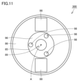
図11は、ホルダ300の構成を示す底面模式図である。図11において、第1方向101に見たホルダ300の構成が示されている。図11に示されるように、ホルダ300において、複数の吐出口98が形成されている。具体的には、第2前端面96において、複数の吐出口98が設けられている。吐出口98は、切削液が吐出される開口部である。吐出口98の数は、たとえば3個である。軸線Aに沿って見て、複数の吐出口98は、たとえば軸線Aに対して3回対称となるように位置している。 FIG. 11 is a schematic bottom view showing the configuration of the holder 300. In FIG. 11, the configuration of the holder 300 as seen in the first direction 101 is shown. As shown in FIG. 11, a plurality of discharge ports 98 are formed in the holder 300. Specifically, a plurality of discharge ports 98 are provided in the second front end surface 96 . The discharge port 98 is an opening through which cutting fluid is discharged. The number of discharge ports 98 is, for example, three. When viewed along the axis A, the plurality of discharge ports 98 are positioned, for example, three times symmetrically with respect to the axis A.

図11に示されるように、ホルダ300は、たとえば2つの突起部88を有している。軸線Aに沿って見て、2つの突起部88の間に挿入部85が位置している。 As shown in FIG. 11, the holder 300 has, for example, two protrusions 88. When viewed along the axis A, the insertion portion 85 is located between the two protrusions 88 .

図12は、図10のXII-XII線に沿った横断面模式図である。図12に示される断面は、軸線Aに垂直であり且つ、第1部材10とホルダ300との間を通る断面である。図12において、断面に投影された吐出口98が、破線を用いて示されている。 FIG. 12 is a schematic cross-sectional view taken along line XII-XII in FIG. The cross section shown in FIG. 12 is perpendicular to the axis A and is a cross section passing between the first member 10 and the holder 300. In FIG. 12, the outlet 98 projected on the cross section is shown using a dashed line.

図12に示されるように、第1部材10と第2部材20と支持部材30とは、少なくとも1つの流入口99を形成している。具体的には、第1部材10と第2部材20と支持部材30とは、たとえば3つの流入口99を形成している。流入口99は、被挿入穴95(図3参照)と空間92(図3参照)との間に位置している。流入口99は、被挿入穴95と空間92とを繋いでいる。 As shown in FIG. 12, the first member 10, the second member 20, and the support member 30 form at least one inlet 99. Specifically, the first member 10, the second member 20, and the support member 30 form, for example, three inflow ports 99. The inflow port 99 is located between the insertion hole 95 (see FIG. 3) and the space 92 (see FIG. 3). The inlet 99 connects the insertion hole 95 and the space 92.

図12に示されるように、軸線Aに沿って見て、吐出口98は、流入口99に重なっている。具体的には、軸線Aに沿って見て、少なくとも1つの吐出口98は、少なくとも1つの流入口99に重なっている。軸線Aに沿って見て、吐出口98の一部は、傾斜面15に重なっていてもよい。径方向において、吐出口98は、第1内周面12と第2内周面22との間に位置している。 As shown in FIG. 12, the outlet 98 overlaps the inlet 99 when viewed along the axis A. Specifically, when viewed along axis A, at least one outlet 98 overlaps at least one inlet 99 . When viewed along the axis A, a portion of the discharge port 98 may overlap the inclined surface 15. The discharge port 98 is located between the first inner circumferential surface 12 and the second inner circumferential surface 22 in the radial direction.

図12に示されるように、軸線Aに沿って見て、1つの流入口99に対して、1つの吐出口98が重なっている。吐出口98の数は、たとえば流入口99の数と同じである。吐出口98および流入口99の各々の数は、特に限定されない。 As shown in FIG. 12, when viewed along the axis A, one inlet 99 overlaps one outlet 98. The number of discharge ports 98 is, for example, the same as the number of inflow ports 99. The number of each of the discharge ports 98 and the inflow ports 99 is not particularly limited.

次に、本実施形態に係る切削工具500の作用効果について説明する。
切削工具500を用いて切削が行われる際において、ボディ100内に切削液が供給される。図10に示されるように、切削液は、ホルダ300から第1矢印131の方向に沿って流れる。具体的には、切削液は、吐出口98から空間92に流入する。切削液は、空間92から流路50を通って、ボディ100の外側に吐出される。
Next, the effects of the cutting tool 500 according to this embodiment will be explained.
When cutting is performed using the cutting tool 500, cutting fluid is supplied into the body 100. As shown in FIG. 10, the cutting fluid flows from the holder 300 along the direction of the first arrow 131. Specifically, the cutting fluid flows into the space 92 from the discharge port 98 . The cutting fluid is discharged from the space 92 to the outside of the body 100 through the flow path 50 .

図13は、切削インサート200の周辺における切削液の流れを示す拡大斜視模式図である。図13に示される拡大斜視模式図は、図6に示される拡大斜視模式図に対応している。図13に示されるように、流路50から吐出された切削液は、第2矢印132に沿って、切削インサート200に向かって流れる。以上により切削インサート200に対して切削液が供給される。 FIG. 13 is an enlarged schematic perspective view showing the flow of cutting fluid around the cutting insert 200. The enlarged perspective schematic diagram shown in FIG. 13 corresponds to the enlarged perspective schematic diagram shown in FIG. 6. As shown in FIG. 13, the cutting fluid discharged from the flow path 50 flows toward the cutting insert 200 along the second arrow 132. As described above, cutting fluid is supplied to the cutting insert 200.

ボディ100に空間92が形成されていない場合、切削液は、第1貫通孔91を通ってボディ100の外側に流出する。具体的には、切削液は、第2締結ネジ400と第2内周面部14との間を通って、第3方向103に沿ってボディ100の外側に流出する。本開示に係る切削工具500は、第1部材10と第2部材20とを有している。第1部材10と第2部材20との間に空間92が形成されている。空間92は、第1貫通孔91を取り囲んでいる。第2部材20において、空間92に連なり第2外周面21において開口している流路50が形成されている。このため、ボディ100内に供給された切削液は、空間92内に流入する。これによって、第1貫通孔91内に流出する切削液の流量を低減できる。このため、切削液が、第1貫通孔91を通ってボディ100の外側に流出することを抑制できる。結果として、空間92が形成されていない場合と比較して、第2外周面21から吐出される切削液の流量を増大できる。 If the space 92 is not formed in the body 100, the cutting fluid flows out of the body 100 through the first through hole 91. Specifically, the cutting fluid passes between the second fastening screw 400 and the second inner circumferential surface portion 14 and flows out of the body 100 along the third direction 103. A cutting tool 500 according to the present disclosure includes a first member 10 and a second member 20. A space 92 is formed between the first member 10 and the second member 20. Space 92 surrounds first through hole 91 . In the second member 20, a flow path 50 is formed which is continuous with the space 92 and is open at the second outer circumferential surface 21. Therefore, the cutting fluid supplied into the body 100 flows into the space 92. Thereby, the flow rate of cutting fluid flowing into the first through hole 91 can be reduced. Therefore, it is possible to suppress the cutting fluid from flowing out to the outside of the body 100 through the first through hole 91. As a result, the flow rate of the cutting fluid discharged from the second outer circumferential surface 21 can be increased compared to the case where the space 92 is not formed.

本開示に係る切削工具500によれば、空間92が切削液専用の流路として機能する。このため、空間92が形成されていない場合と比較して、切削液の流れの圧力損失を低減することができる。 According to the cutting tool 500 according to the present disclosure, the space 92 functions as a channel exclusively for cutting fluid. Therefore, the pressure loss of the cutting fluid flow can be reduced compared to the case where the space 92 is not formed.

本開示に係る切削工具500によれば、流路50に流入する前の切削液を、一時的に空間92内に保持することができる。これによって、空間92から複数の流路50の各々に流れ込む切削液の流量を均一化することができる。結果として、複数の流路50の各々から吐出される切削液の流量を均一化できる。 According to the cutting tool 500 according to the present disclosure, the cutting fluid before flowing into the flow path 50 can be temporarily held in the space 92. Thereby, the flow rate of the cutting fluid flowing from the space 92 into each of the plurality of channels 50 can be made uniform. As a result, the flow rate of the cutting fluid discharged from each of the plurality of channels 50 can be made uniform.

本開示に係る切削工具500によれば、ボディ100は、支持部材30を有している。支持部材30は、第1外周面11と第2内周面22とを繋いでいる。支持部材30は、第1前端面1および第1後端面2の各々から離間している。このため、切削工具500を用いて切削が行われる際における第1部材10および第2部材20の各々の振動を抑制できる。 According to the cutting tool 500 according to the present disclosure, the body 100 includes the support member 30. The support member 30 connects the first outer peripheral surface 11 and the second inner peripheral surface 22. The support member 30 is spaced apart from each of the first front end surface 1 and the first rear end surface 2. Therefore, vibration of each of the first member 10 and the second member 20 when cutting is performed using the cutting tool 500 can be suppressed.

本開示に係る切削工具500によれば、軸線Aに沿って見て、第3流路部53は湾曲している。このため、第3流路部53の設計自由度を向上しつつ、第3流路部53を流れる切削液の圧力損失を低減できる。 According to the cutting tool 500 according to the present disclosure, the third flow path section 53 is curved when viewed along the axis A. Therefore, the degree of freedom in designing the third flow path section 53 can be improved, and the pressure loss of the cutting fluid flowing through the third flow path section 53 can be reduced.

本開示に係る切削工具500によれば、流路50は、第1流路部51を有している。第1流路部51は、すくい面81に向かって開口している。このため、すくい面81に連なる切刃84を効果的に冷却できる。 According to the cutting tool 500 according to the present disclosure, the flow path 50 includes the first flow path section 51. The first flow path section 51 is open toward the rake surface 81. Therefore, the cutting edge 84 connected to the rake face 81 can be effectively cooled.

本開示に係る切削工具500によれば、流路50は、第3流路部53を有している。第3流路部53は、逃げ面82に向かって開口している。このため、逃げ面82に連なる切刃84を効果的に冷却できる。 According to the cutting tool 500 according to the present disclosure, the flow path 50 includes the third flow path section 53. The third flow path section 53 is open toward the flank surface 82. Therefore, the cutting edge 84 connected to the flank 82 can be effectively cooled.

3次元プリンタを用いてボディ100を形成する場合、3次元プリンタの積層方向に垂直な方向に突出する部分を形成する際にサポート材が必要になる。この場合、ボディ100からサポート材を除去する必要がある。この結果、ボディ100の形成に必要な時間が増大する。本開示に係る切削工具500によれば、第1部材10は、第1内周面12を有している。第1内周面12は、第2内周面部14を有している。第2内周面部14の直径は、第1前端面1から離間するにつれて小さくなっている。言い換えれば、第2内周面部14は、第1方向101に垂直な方向に対して傾斜している。このため、3次元プリンタの積層方向が第1方向101である場合、第2内周面部14の形成において、サポート材の使用量を低減できる。この結果、ボディ100の形成に必要な時間を低減できる。 When forming the body 100 using a three-dimensional printer, a support material is required when forming a portion that protrudes in a direction perpendicular to the stacking direction of the three-dimensional printer. In this case, it is necessary to remove the support material from the body 100. As a result, the time required to form body 100 increases. According to the cutting tool 500 according to the present disclosure, the first member 10 has the first inner peripheral surface 12. The first inner circumferential surface 12 has a second inner circumferential surface portion 14 . The diameter of the second inner circumferential surface portion 14 becomes smaller as the distance from the first front end surface 1 increases. In other words, the second inner circumferential surface portion 14 is inclined with respect to a direction perpendicular to the first direction 101. Therefore, when the stacking direction of the three-dimensional printer is the first direction 101, the amount of support material used can be reduced in forming the second inner circumferential surface portion 14. As a result, the time required to form the body 100 can be reduced.

本開示に係る切削工具500によれば、ホルダ300において、少なくとも1つの吐出口98が設けられている。ボディ100において少なくとも一つの流入口99が形成されている。軸線Aに沿って見て、少なくとも1つの吐出口98は、少なくとも1つの流入口99に重なっている。このため、軸線Aに沿って見て吐出口98が流入口99に重なっていない場合と比較して、吐出口98と流入口99との間の距離が短くなる。これによって、吐出口98から吐出された切削液が流入口99に向かって流れる際に、切削液の圧力損失を低減できる。 According to the cutting tool 500 according to the present disclosure, at least one discharge port 98 is provided in the holder 300. At least one inlet 99 is formed in the body 100. Viewed along axis A, at least one outlet 98 overlaps at least one inlet 99 . Therefore, the distance between the discharge port 98 and the inflow port 99 becomes shorter compared to the case where the discharge port 98 does not overlap the inflow port 99 when viewed along the axis A. Thereby, when the cutting fluid discharged from the discharge port 98 flows toward the inflow port 99, the pressure loss of the cutting fluid can be reduced.

(サンプル準備)
まず、サンプル1およびサンプル2に係る切削工具500を準備した。サンプル1に係る切削工具500は、比較例である。サンプル2に係る切削工具500は、実施例である。
(sample preparation)
First, cutting tools 500 according to Sample 1 and Sample 2 were prepared. The cutting tool 500 according to Sample 1 is a comparative example. The cutting tool 500 according to sample 2 is an example.

サンプル1に係る切削工具500においては、空間92は形成されなかった。言い換えれば、サンプル1に係る切削工具500においては、流路50は、第1貫通孔91に連なっていた。サンプル2に係る切削工具500の構成は、図10から図12に示される切削工具500の構成とした。具体的には、サンプル2に係る切削工具500においては、空間92が形成されていた。 In the cutting tool 500 according to Sample 1, the space 92 was not formed. In other words, in the cutting tool 500 according to Sample 1, the flow path 50 was continuous with the first through hole 91. The configuration of the cutting tool 500 according to Sample 2 was the configuration of the cutting tool 500 shown in FIGS. 10 to 12. Specifically, in the cutting tool 500 according to Sample 2, a space 92 was formed.

(評価方法)
次に、サンプル1およびサンプル2に係る切削工具500を用いて、切削液の吐出量の均一性を評価した。具体的には、回転方向Rにおいて並んでいる3つのポケット70を1つの段として、15個のポケット70を5つの段に分類した。5つの段の各々において、開口部150から吐出された切削液の量の合計値を測定した。全ての開口部150から吐出された切削液の量の合計値に対する5つの段の各々において吐出された切削液の量の割合を算出した。
(Evaluation method)
Next, using the cutting tools 500 according to Sample 1 and Sample 2, the uniformity of the discharge amount of cutting fluid was evaluated. Specifically, three pockets 70 lined up in the rotational direction R were treated as one stage, and the 15 pockets 70 were classified into five stages. In each of the five stages, the total amount of cutting fluid discharged from the opening 150 was measured. The ratio of the amount of cutting fluid discharged at each of the five stages to the total amount of cutting fluid discharged from all the openings 150 was calculated.

(評価結果) (Evaluation results)

Figure 0007343076000001

表1は、サンプル1およびサンプル2に係る切削工具500の各列における吐出量の割合を示している。表1において、1段目とは上記の5つの段の内、第1後端面2に最も近い段を示している。1段目以外の4つの段は、1段目から第3方向103に向かうにつれて、順に2段目から5段目とした。 Table 1 shows the ratio of the discharge amount in each row of the cutting tool 500 according to Sample 1 and Sample 2. In Table 1, the first stage indicates the stage closest to the first rear end surface 2 among the five stages mentioned above. The four stages other than the first stage were arranged as the second stage to the fifth stage in order from the first stage toward the third direction 103.

表1に示されるように、サンプル1に係る切削工具500において、1段目から5段目の各々の吐出量の割合は、7%以上28%以下であった。サンプル2に係る切削工具500において、1段目から5段目の各々の吐出量の割合は、18%以上21%以下であった。 As shown in Table 1, in the cutting tool 500 according to Sample 1, the ratio of the discharge amount of each of the first to fifth stages was 7% or more and 28% or less. In the cutting tool 500 according to Sample 2, the ratio of the discharge amount of each of the first to fifth stages was 18% or more and 21% or less.

以上の結果より、比較例の切削工具500と比較して、実施例の切削工具500においては、軸線Aに沿った方向において切削液の吐出量の均一性が向上されていることが確認できた。 From the above results, it was confirmed that the uniformity of the discharge amount of cutting fluid in the direction along the axis A was improved in the cutting tool 500 of the example compared to the cutting tool 500 of the comparative example. .

今回開示された実施形態および実施例は全ての点で例示であって、制限的なものではないと考えられるべきである。本発明の範囲は、上記した実施形態ではなく、請求の範囲によって示され、請求の範囲と均等の意味及び範囲内での全ての変更が含まれることが意図される。 The embodiments and examples disclosed herein are illustrative in all respects and should not be considered restrictive. The scope of the present invention is indicated by the claims rather than the embodiments described above, and it is intended that all changes within the meaning and range equivalent to the claims are included.

1 第1前端面(前端面)、2 第1後端面(後端面)、10 第1部材、11 第1外周面、12 第1内周面、13 第1内周面部、14 第2内周面部、15 傾斜面、20 第2部材、21 第2外周面(最外周面)、22 第2内周面(内周面)、30 支持部材、34 第4面、35 第5面、40 固定部材、41 第1座面(座面)、42 第2座面、43 第3座面、45 第3面、50 流路、51 第1流路部、52 第2流路部、53 第3流路部(流路部)、54 第4流路部、55 第5流路部、61 第1面、62 第2面、68 最外周面部、70 ポケット、79 第2貫通孔、80 平面、81 すくい面、82 逃げ面、83 底面、84 切刃、85 挿入部、86 ベース部、87 接続部、88 突起部、89 第2ネジ穴、90 第1締結ネジ、91 第1貫通孔(貫通孔)、92 空間、93 第1ネジ穴、94 溝部、95 被挿入穴、96 第2前端面、97 第2後端面、98 吐出口、99 流入口、100 ボディ、101 第1方向、102 第2方向、103 第3方向、131 第1矢印、132 第2矢印、150 開口部、151 第1開口部、152 第2開口部、153 第3開口部、154 第4開口部、155 第5開口部、160 接続口、200 切削インサート、300 ホルダ、400 第2締結ネジ、401 ネジ部、402 頭部、500 切削工具、A 軸線、R 回転方向、W1 第1幅、W2 第2幅。 1 First front end surface (front end surface), 2 First rear end surface (rear end surface), 10 First member, 11 First outer circumferential surface, 12 First inner circumferential surface, 13 First inner circumferential surface, 14 Second inner circumference Surface part, 15 Inclined surface, 20 Second member, 21 Second outer circumferential surface (outermost circumferential surface), 22 Second inner circumferential surface (inner circumferential surface), 30 Support member, 34 Fourth surface, 35 Fifth surface, 40 Fixation Member, 41 first seat surface (seat surface), 42 second seat surface, 43 third seat surface, 45 third surface, 50 channel, 51 first channel section, 52 second channel section, 53 third Flow path section (flow path section), 54 4th flow path section, 55 5th flow path section, 61 1st surface, 62 2nd surface, 68 outermost peripheral surface section, 70 pocket, 79 2nd through hole, 80 plane, 81 rake face, 82 flank face, 83 bottom face, 84 cutting edge, 85 insertion part, 86 base part, 87 connection part, 88 projection part, 89 second screw hole, 90 first fastening screw, 91 first through hole (through hole), 92 space, 93 first screw hole, 94 groove, 95 insertion hole, 96 second front end surface, 97 second rear end surface, 98 discharge port, 99 inflow port, 100 body, 101 first direction, 102 first direction 2 directions, 103 3rd direction, 131 1st arrow, 132 2nd arrow, 150 opening, 151 1st opening, 152 2nd opening, 153 3rd opening, 154 4th opening, 155 5th opening part, 160 connection port, 200 cutting insert, 300 holder, 400 second fastening screw, 401 threaded part, 402 head, 500 cutting tool, A axis, R rotation direction, W1 first width, W2 second width.

Claims (10)

軸線の周りを回転可能に構成された切削工具であって、
前端面と、前記前端面の反対にある後端面と、前記前端面および前記後端面の各々に連なり且つポケットが形成されている最外周面とを含むボディと、
前記ポケットに配置される切削インサートとを備え、
前記ボディは、
前記軸線を取り囲んでおり、第1外周面を有する第1部材と、
前記第1外周面を取り囲む内周面を有し且つ前記前端面、前記後端面および前記最外周面の各々を形成している第2部材と、
前記第1外周面と前記内周面とを繋いでおり且つ前記前端面および前記後端面の各々から離間している支持部材と、
前記第1外周面と前記内周面の間の隙間を塞ぐ固定部材とを含み、
前記第1部材には、前記軸線に沿って延びる貫通孔が形成されており、
前記第1部材と前記第2部材との間において、空間が形成されており、
前記空間は、前記貫通孔を取り囲んでおり、
前記第2部材において、前記空間に連なり且つ前記最外周面において開口している流路が形成されており、
前記支持部材は、前記第1外周面および前記内周面の全周の一部を支持しており、
前記固定部材は、第3面を有しており、
前記第3面は、前記第1外周面および前記内周面の各々に連なっており、
前記第1外周面、前記内周面および前記第3面は、前記空間を形成している、切削工具。
A cutting tool configured to be rotatable around an axis,
a body including a front end surface, a rear end surface opposite to the front end surface, and an outermost peripheral surface continuous with each of the front end surface and the rear end surface and having a pocket formed therein;
a cutting insert disposed in the pocket;
The body is
a first member surrounding the axis and having a first outer peripheral surface;
a second member having an inner peripheral surface surrounding the first outer peripheral surface and forming each of the front end surface, the rear end surface, and the outermost peripheral surface;
a support member that connects the first outer circumferential surface and the inner circumferential surface and is spaced apart from each of the front end surface and the rear end surface;
a fixing member closing a gap between the first outer circumferential surface and the inner circumferential surface,
A through hole extending along the axis is formed in the first member,
A space is formed between the first member and the second member,
The space surrounds the through hole,
In the second member, a flow path is formed that is continuous with the space and is open at the outermost peripheral surface ,
The support member supports part of the entire circumference of the first outer peripheral surface and the inner peripheral surface,
The fixing member has a third surface,
The third surface is continuous with each of the first outer circumferential surface and the inner circumferential surface,
The cutting tool , wherein the first outer circumferential surface, the inner circumferential surface, and the third surface form the space .
前記流路は、前記軸線に沿って見て湾曲している流路部を有している、請求項1に記載の切削工具。 The cutting tool according to claim 1, wherein the flow path has a curved flow path portion when viewed along the axis. 前記流路が延びる方向に垂直な断面において、前記流路の形状は、楕円形状である、請求項1または請求項2に記載の切削工具。 The cutting tool according to claim 1 or 2, wherein the flow path has an elliptical shape in a cross section perpendicular to the direction in which the flow path extends. 前記流路が延びる方向に垂直な断面において、前記前端面から前記後端面に向かう第1方向における前記流路の幅を第1幅とし、前記第1方向に垂直な第2方向における前記流路の幅を第2幅とした場合、
前記第1幅は、前記第2幅よりも大きい、請求項1または請求項2に記載の切削工具。
In a cross section perpendicular to the direction in which the flow path extends, the width of the flow path in a first direction from the front end surface to the rear end surface is defined as a first width, and the flow path in a second direction perpendicular to the first direction. If the width of is set as the second width,
The cutting tool according to claim 1 or 2, wherein the first width is larger than the second width.
前記切削インサートは、前記最外周面に接する底面と、前記底面の反対にあるすくい面とを含み、
前記最外周面は、前記底面に接する座面と、前記座面に対して回転方向の前方にある第1面とを有し、
前記座面および前記第1面は、前記ポケットを形成しており、
前記流路は、前記第1面において開口している第1流路部を有し、
前記第1流路部は、前記すくい面に向かって開口している、請求項1または請求項2に記載の切削工具。
The cutting insert includes a bottom surface in contact with the outermost peripheral surface and a rake surface opposite to the bottom surface,
The outermost peripheral surface has a seat surface in contact with the bottom surface, and a first surface located in front of the seat surface in the rotation direction,
The seat surface and the first surface form the pocket,
The flow path has a first flow path portion that is open on the first surface,
The cutting tool according to claim 1 or 2, wherein the first flow path portion is open toward the rake face.
前記流路は、前記第1面において開口しており且つ前記第1流路部から離間している第2流路部を有し、
前記第2流路部は、前記すくい面に向かって開口しており、
前記第1面において、前記第1流路部に連なる第1開口部と、前記第2流路部に連なる第2開口部とが形成されており、
前記第1開口部の面積は、前記第2開口部の面積と異なっている、請求項5に記載の切削工具。
The flow path has a second flow path portion that is open on the first surface and is spaced apart from the first flow path portion,
The second flow path portion is open toward the rake surface,
A first opening connected to the first flow path section and a second opening connected to the second flow path section are formed on the first surface,
The cutting tool according to claim 5, wherein the area of the first opening is different from the area of the second opening.
前記流路は、前記第1面において開口しており且つ前記第1流路部から離間している第2流路部を有し、
前記第2流路部は、前記すくい面に向かって開口しており、
前記第1流路部が延びる方向に垂直な断面における前記第1流路部の面積を第1面積とし、前記第2流路部が延びる方向に垂直な断面における前記第2流路部の面積を第2面積とした場合、
前記第1面積は、前記第2面積と異なっている、請求項5に記載の切削工具。
The flow path has a second flow path portion that is open on the first surface and is spaced apart from the first flow path portion,
The second flow path portion is open toward the rake surface,
The area of the first flow path section in a cross section perpendicular to the direction in which the first flow path section extends is defined as a first area, and the area of the second flow path section in a cross section perpendicular to the direction in which the second flow path section extends. When is the second area,
6. The cutting tool of claim 5, wherein the first area is different from the second area.
前記切削インサートは、前記すくい面に連なる逃げ面を含み、
前記最外周面は、前記座面に対して前記回転方向の後方に位置しており且つ前記座面に対して前記軸線から前記最外周面に向かう方向に位置している第2面を有し、
前記流路は、前記第2面において開口している第3流路部を有し、
前記第3流路部は、前記逃げ面に向かって開口している、請求項5に記載の切削工具。
The cutting insert includes a flank face continuous with the rake face,
The outermost circumferential surface has a second surface that is located at the rear of the seat surface in the rotational direction and that is located in a direction from the axis toward the outermost surface with respect to the seat surface. ,
The flow path has a third flow path portion that is open on the second surface,
The cutting tool according to claim 5, wherein the third flow path section is open toward the flank surface.
前記第1部材は、前記貫通孔を形成している第1内周面を含み、
前記第1内周面は、
前記軸線に沿って延びる第1内周面部と、
前記第1内周面部と前記前端面との間に位置し、且つ前記第1内周面部に対して傾斜している第2内周面部とを有し、
前記第2内周面部の直径は、前記前端面から離間するにつれて小さくなっている、請求項1または請求項2に記載の切削工具。
The first member includes a first inner circumferential surface forming the through hole,
The first inner circumferential surface is
a first inner peripheral surface portion extending along the axis;
a second inner circumferential surface portion located between the first inner circumferential surface portion and the front end surface and inclined with respect to the first inner circumferential surface portion;
The cutting tool according to claim 1 or 2, wherein the diameter of the second inner circumferential surface portion becomes smaller as the distance from the front end surface increases.
前記空間に切削液を供給するように構成されているホルダをさらに備え、
前記ホルダにおいて、少なくとも1つの吐出口が形成されており、
前記第1部材と前記第2部材と前記支持部材とは、前記空間に連なる少なくとも1つの流入口を形成しており、
前記軸線に沿って見て、前記少なくとも1つの吐出口は、前記少なくとも1つの流入口に重なっており、
前記少なくとも1つの吐出口の数は、前記少なくとも1つの流入口の数と同じである、請求項1または請求項2に記載の切削工具。
further comprising a holder configured to supply cutting fluid to the space,
At least one discharge port is formed in the holder,
The first member, the second member, and the support member form at least one inlet that connects to the space,
Viewed along the axis, the at least one outlet overlaps the at least one inlet;
The cutting tool according to claim 1 or claim 2, wherein the number of the at least one outlet is the same as the number of the at least one inlet.
JP2023512674A 2022-11-02 2022-11-02 Cutting tools Active JP7343076B1 (en)

Applications Claiming Priority (1)

Application Number Priority Date Filing Date Title
JP2022041008 2022-11-02

Publications (1)

Publication Number Publication Date
JP7343076B1 true JP7343076B1 (en) 2023-09-12

Family

ID=87934850

Family Applications (1)

Application Number Title Priority Date Filing Date
JP2023512674A Active JP7343076B1 (en) 2022-11-02 2022-11-02 Cutting tools

Country Status (1)

Country Link
JP (1) JP7343076B1 (en)

Citations (6)

* Cited by examiner, † Cited by third party
Publication number Priority date Publication date Assignee Title
JP2018149655A (en) 2017-03-14 2018-09-27 三菱マテリアル株式会社 Holder for cutting edge replacement type cutting tool, and cutting edge replacement type cutting tool
JP2018149656A (en) 2017-03-14 2018-09-27 三菱マテリアル株式会社 Holder for cutting edge replacement type cutting tool, and cutting edge replacement type cutting tool
JP2020163544A (en) 2019-03-29 2020-10-08 三菱マテリアル株式会社 Cutting insert and rolling tool
US20210101214A1 (en) 2019-10-08 2021-04-08 Kennametal Inc. Cutting Tool
US20210220956A1 (en) 2020-01-22 2021-07-22 Kennametal Inc. Indexable milling cutter with precise coolant streams
CN214079467U (en) 2020-10-19 2021-08-31 松德刀具(长兴)科技有限公司 Corn milling cutter

Patent Citations (6)

* Cited by examiner, † Cited by third party
Publication number Priority date Publication date Assignee Title
JP2018149655A (en) 2017-03-14 2018-09-27 三菱マテリアル株式会社 Holder for cutting edge replacement type cutting tool, and cutting edge replacement type cutting tool
JP2018149656A (en) 2017-03-14 2018-09-27 三菱マテリアル株式会社 Holder for cutting edge replacement type cutting tool, and cutting edge replacement type cutting tool
JP2020163544A (en) 2019-03-29 2020-10-08 三菱マテリアル株式会社 Cutting insert and rolling tool
US20210101214A1 (en) 2019-10-08 2021-04-08 Kennametal Inc. Cutting Tool
US20210220956A1 (en) 2020-01-22 2021-07-22 Kennametal Inc. Indexable milling cutter with precise coolant streams
CN214079467U (en) 2020-10-19 2021-08-31 松德刀具(长兴)科技有限公司 Corn milling cutter

Similar Documents

Publication Publication Date Title
EP3153263B1 (en) A slot milling disc and a slot milling tool comprising such a slot milling disc
JP7015832B2 (en) Machining tool
JP5591409B2 (en) Cutting insert, cutting tool and method of manufacturing workpiece
JP5491505B2 (en) Milling and cutting tips therefor
KR102307031B1 (en) Cutting tool having a cooling chamber and tool body with integrally formed coolant deflection
JP6882982B2 (en) Rotating chuck with cooling groove
KR101380422B1 (en) A boring bar for internal turning
JP4965667B2 (en) drill
JPWO2012117813A1 (en) Guide pad, cutting tool body and cutting tool
JP6621044B1 (en) Cutting inserts and milling tools
JP6955107B2 (en) Tools for machining workpieces
JP6568303B2 (en) Cutting tool insert
JP5944527B2 (en) Cutting insert, cutting tool, and method of manufacturing cut workpiece
JP7057550B1 (en) Cutting tools
JP7343076B1 (en) Cutting tools
JP6874292B2 (en) Part-Time Job
JP2022519440A (en) Rotary cutting tools, rotary cutting tools and inserts with insert pockets with seating surfaces with multiple contact elements
US20210101214A1 (en) Cutting Tool
JP5286928B2 (en) End mill
JP2008044038A (en) Ball endmill
JP5967328B1 (en) Drilling tool
RU2738868C1 (en) Vortex processing tool
WO2019220778A9 (en) Cutting insert for drill, and drill
JP2012206205A (en) Drill holder, and cutting-edge replaceable drill
WO2023090153A1 (en) Holder, cutting tool, and method for manufacturing machined product

Legal Events

Date Code Title Description
A521 Request for written amendment filed

Free format text: JAPANESE INTERMEDIATE CODE: A523

Effective date: 20230221

A621 Written request for application examination

Free format text: JAPANESE INTERMEDIATE CODE: A621

Effective date: 20230221

A871 Explanation of circumstances concerning accelerated examination

Free format text: JAPANESE INTERMEDIATE CODE: A871

Effective date: 20230221

A131 Notification of reasons for refusal

Free format text: JAPANESE INTERMEDIATE CODE: A131

Effective date: 20230523

A521 Request for written amendment filed

Free format text: JAPANESE INTERMEDIATE CODE: A523

Effective date: 20230714

TRDD Decision of grant or rejection written
A01 Written decision to grant a patent or to grant a registration (utility model)

Free format text: JAPANESE INTERMEDIATE CODE: A01

Effective date: 20230801

A61 First payment of annual fees (during grant procedure)

Free format text: JAPANESE INTERMEDIATE CODE: A61

Effective date: 20230814

R150 Certificate of patent or registration of utility model

Ref document number: 7343076

Country of ref document: JP

Free format text: JAPANESE INTERMEDIATE CODE: R150