JP7343060B2 - Resin film for current collector sheet, current collector sheet, solar cell element with current collector sheet, and solar cell - Google Patents
Resin film for current collector sheet, current collector sheet, solar cell element with current collector sheet, and solar cell Download PDFInfo
- Publication number
- JP7343060B2 JP7343060B2 JP2022571873A JP2022571873A JP7343060B2 JP 7343060 B2 JP7343060 B2 JP 7343060B2 JP 2022571873 A JP2022571873 A JP 2022571873A JP 2022571873 A JP2022571873 A JP 2022571873A JP 7343060 B2 JP7343060 B2 JP 7343060B2
- Authority
- JP
- Japan
- Prior art keywords
- current collector
- solar cell
- collector sheet
- resin film
- resin
- Prior art date
- Legal status (The legal status is an assumption and is not a legal conclusion. Google has not performed a legal analysis and makes no representation as to the accuracy of the status listed.)
- Active
Links
- 229920005989 resin Polymers 0.000 title claims description 261
- 239000011347 resin Substances 0.000 title claims description 261
- 238000007789 sealing Methods 0.000 claims description 106
- -1 polypropylene Polymers 0.000 claims description 67
- 239000004743 Polypropylene Substances 0.000 claims description 45
- 238000002834 transmittance Methods 0.000 claims description 41
- 229920001155 polypropylene Polymers 0.000 claims description 40
- 239000008393 encapsulating agent Substances 0.000 claims description 35
- 238000002844 melting Methods 0.000 claims description 33
- 230000008018 melting Effects 0.000 claims description 33
- 239000000758 substrate Substances 0.000 claims description 33
- 229920005672 polyolefin resin Polymers 0.000 claims description 32
- 239000004611 light stabiliser Substances 0.000 claims description 26
- 229920000573 polyethylene Polymers 0.000 claims description 20
- 229920013716 polyethylene resin Polymers 0.000 claims description 18
- 239000004698 Polyethylene Substances 0.000 claims description 16
- 229920001971 elastomer Polymers 0.000 claims description 15
- 239000000806 elastomer Substances 0.000 claims description 15
- 239000006097 ultraviolet radiation absorber Substances 0.000 claims description 15
- 238000003860 storage Methods 0.000 claims description 14
- 229920005633 polypropylene homopolymer resin Polymers 0.000 claims description 10
- 229920000034 Plastomer Polymers 0.000 claims description 7
- 239000010410 layer Substances 0.000 description 243
- 239000010408 film Substances 0.000 description 186
- 238000000034 method Methods 0.000 description 39
- 238000005259 measurement Methods 0.000 description 27
- 238000012360 testing method Methods 0.000 description 25
- 238000004519 manufacturing process Methods 0.000 description 22
- 239000004711 α-olefin Substances 0.000 description 17
- 239000003566 sealing material Substances 0.000 description 15
- 229920000139 polyethylene terephthalate Polymers 0.000 description 14
- 239000005020 polyethylene terephthalate Substances 0.000 description 14
- 230000006750 UV protection Effects 0.000 description 13
- 239000000463 material Substances 0.000 description 12
- 239000012790 adhesive layer Substances 0.000 description 10
- 239000011342 resin composition Substances 0.000 description 9
- 229920000089 Cyclic olefin copolymer Polymers 0.000 description 8
- 150000001412 amines Chemical class 0.000 description 8
- 238000004458 analytical method Methods 0.000 description 8
- 229920000840 ethylene tetrafluoroethylene copolymer Polymers 0.000 description 8
- 229920001684 low density polyethylene Polymers 0.000 description 7
- 239000004702 low-density polyethylene Substances 0.000 description 7
- 238000010248 power generation Methods 0.000 description 7
- VGGSQFUCUMXWEO-UHFFFAOYSA-N Ethene Chemical compound C=C VGGSQFUCUMXWEO-UHFFFAOYSA-N 0.000 description 6
- 239000005977 Ethylene Substances 0.000 description 6
- 125000004432 carbon atom Chemical group C* 0.000 description 6
- 239000011229 interlayer Substances 0.000 description 6
- 239000000126 substance Substances 0.000 description 6
- 230000000930 thermomechanical effect Effects 0.000 description 6
- 229920005992 thermoplastic resin Polymers 0.000 description 6
- 230000000052 comparative effect Effects 0.000 description 5
- 230000007423 decrease Effects 0.000 description 5
- 230000005611 electricity Effects 0.000 description 5
- 238000010438 heat treatment Methods 0.000 description 5
- 238000007373 indentation Methods 0.000 description 5
- 239000000203 mixture Substances 0.000 description 5
- 238000011160 research Methods 0.000 description 5
- 239000002356 single layer Substances 0.000 description 5
- 238000009823 thermal lamination Methods 0.000 description 5
- VXNZUUAINFGPBY-UHFFFAOYSA-N 1-Butene Chemical compound CCC=C VXNZUUAINFGPBY-UHFFFAOYSA-N 0.000 description 4
- ZGEGCLOFRBLKSE-UHFFFAOYSA-N 1-Heptene Chemical compound CCCCCC=C ZGEGCLOFRBLKSE-UHFFFAOYSA-N 0.000 description 4
- AFFLGGQVNFXPEV-UHFFFAOYSA-N 1-decene Chemical compound CCCCCCCCC=C AFFLGGQVNFXPEV-UHFFFAOYSA-N 0.000 description 4
- CRSBERNSMYQZNG-UHFFFAOYSA-N 1-dodecene Chemical compound CCCCCCCCCCC=C CRSBERNSMYQZNG-UHFFFAOYSA-N 0.000 description 4
- LIKMAJRDDDTEIG-UHFFFAOYSA-N 1-hexene Chemical compound CCCCC=C LIKMAJRDDDTEIG-UHFFFAOYSA-N 0.000 description 4
- KWKAKUADMBZCLK-UHFFFAOYSA-N 1-octene Chemical compound CCCCCCC=C KWKAKUADMBZCLK-UHFFFAOYSA-N 0.000 description 4
- WSSSPWUEQFSQQG-UHFFFAOYSA-N 4-methyl-1-pentene Chemical compound CC(C)CC=C WSSSPWUEQFSQQG-UHFFFAOYSA-N 0.000 description 4
- 125000002252 acyl group Chemical group 0.000 description 4
- 239000000654 additive Substances 0.000 description 4
- 239000000853 adhesive Substances 0.000 description 4
- 230000001070 adhesive effect Effects 0.000 description 4
- 150000001875 compounds Chemical class 0.000 description 4
- 229920001577 copolymer Polymers 0.000 description 4
- 230000006866 deterioration Effects 0.000 description 4
- 230000000694 effects Effects 0.000 description 4
- 238000010030 laminating Methods 0.000 description 4
- 238000003475 lamination Methods 0.000 description 4
- YWAKXRMUMFPDSH-UHFFFAOYSA-N pentene Chemical compound CCCC=C YWAKXRMUMFPDSH-UHFFFAOYSA-N 0.000 description 4
- QQONPFPTGQHPMA-UHFFFAOYSA-N propylene Natural products CC=C QQONPFPTGQHPMA-UHFFFAOYSA-N 0.000 description 4
- 125000004805 propylene group Chemical group [H]C([H])([H])C([H])([*:1])C([H])([H])[*:2] 0.000 description 4
- 229910000679 solder Inorganic materials 0.000 description 4
- 238000004566 IR spectroscopy Methods 0.000 description 3
- 229920010126 Linear Low Density Polyethylene (LLDPE) Polymers 0.000 description 3
- 238000010521 absorption reaction Methods 0.000 description 3
- 125000000217 alkyl group Chemical group 0.000 description 3
- 238000001125 extrusion Methods 0.000 description 3
- 150000002430 hydrocarbons Chemical group 0.000 description 3
- 239000007769 metal material Substances 0.000 description 3
- 238000000465 moulding Methods 0.000 description 3
- 229920000642 polymer Polymers 0.000 description 3
- 229920001296 polysiloxane Polymers 0.000 description 3
- GQEZCXVZFLOKMC-UHFFFAOYSA-N 1-hexadecene Chemical compound CCCCCCCCCCCCCCC=C GQEZCXVZFLOKMC-UHFFFAOYSA-N 0.000 description 2
- JRZJOMJEPLMPRA-UHFFFAOYSA-N 1-nonene Chemical compound CCCCCCCC=C JRZJOMJEPLMPRA-UHFFFAOYSA-N 0.000 description 2
- HFDVRLIODXPAHB-UHFFFAOYSA-N 1-tetradecene Chemical compound CCCCCCCCCCCCC=C HFDVRLIODXPAHB-UHFFFAOYSA-N 0.000 description 2
- DCTOHCCUXLBQMS-UHFFFAOYSA-N 1-undecene Chemical compound CCCCCCCCCC=C DCTOHCCUXLBQMS-UHFFFAOYSA-N 0.000 description 2
- 229920002799 BoPET Polymers 0.000 description 2
- CURLTUGMZLYLDI-UHFFFAOYSA-N Carbon dioxide Chemical compound O=C=O CURLTUGMZLYLDI-UHFFFAOYSA-N 0.000 description 2
- 238000005481 NMR spectroscopy Methods 0.000 description 2
- 125000002947 alkylene group Chemical group 0.000 description 2
- WPKYZIPODULRBM-UHFFFAOYSA-N azane;prop-2-enoic acid Chemical compound N.OC(=O)C=C WPKYZIPODULRBM-UHFFFAOYSA-N 0.000 description 2
- 239000010949 copper Substances 0.000 description 2
- 238000005520 cutting process Methods 0.000 description 2
- 230000002542 deteriorative effect Effects 0.000 description 2
- 238000000113 differential scanning calorimetry Methods 0.000 description 2
- 229940069096 dodecene Drugs 0.000 description 2
- BXKDSDJJOVIHMX-UHFFFAOYSA-N edrophonium chloride Chemical compound [Cl-].CC[N+](C)(C)C1=CC=CC(O)=C1 BXKDSDJJOVIHMX-UHFFFAOYSA-N 0.000 description 2
- NNBRCHPBPDRPIT-UHFFFAOYSA-N ethenyl(tripropoxy)silane Chemical compound CCCO[Si](OCCC)(OCCC)C=C NNBRCHPBPDRPIT-UHFFFAOYSA-N 0.000 description 2
- 239000005038 ethylene vinyl acetate Substances 0.000 description 2
- 229920001903 high density polyethylene Polymers 0.000 description 2
- 239000004700 high-density polyethylene Substances 0.000 description 2
- TVMXDCGIABBOFY-UHFFFAOYSA-N n-Octanol Natural products CCCCCCCC TVMXDCGIABBOFY-UHFFFAOYSA-N 0.000 description 2
- VAMFXQBUQXONLZ-UHFFFAOYSA-N n-alpha-eicosene Natural products CCCCCCCCCCCCCCCCCCC=C VAMFXQBUQXONLZ-UHFFFAOYSA-N 0.000 description 2
- CCCMONHAUSKTEQ-UHFFFAOYSA-N octadec-1-ene Chemical compound CCCCCCCCCCCCCCCCC=C CCCMONHAUSKTEQ-UHFFFAOYSA-N 0.000 description 2
- 230000035515 penetration Effects 0.000 description 2
- 125000001997 phenyl group Chemical group [H]C1=C([H])C([H])=C(*)C([H])=C1[H] 0.000 description 2
- 230000000704 physical effect Effects 0.000 description 2
- 229920001200 poly(ethylene-vinyl acetate) Polymers 0.000 description 2
- 229920005606 polypropylene copolymer Polymers 0.000 description 2
- 238000003825 pressing Methods 0.000 description 2
- 230000004224 protection Effects 0.000 description 2
- 239000000565 sealant Substances 0.000 description 2
- 230000035945 sensitivity Effects 0.000 description 2
- 229910052709 silver Inorganic materials 0.000 description 2
- 239000007787 solid Substances 0.000 description 2
- 230000003068 static effect Effects 0.000 description 2
- 238000011282 treatment Methods 0.000 description 2
- JYEUMXHLPRZUAT-UHFFFAOYSA-N 1,2,3-triazine Chemical compound C1=CN=NN=C1 JYEUMXHLPRZUAT-UHFFFAOYSA-N 0.000 description 1
- 229940106006 1-eicosene Drugs 0.000 description 1
- FIKTURVKRGQNQD-UHFFFAOYSA-N 1-eicosene Natural products CCCCCCCCCCCCCCCCCC=CC(O)=O FIKTURVKRGQNQD-UHFFFAOYSA-N 0.000 description 1
- YHQXBTXEYZIYOV-UHFFFAOYSA-N 3-methylbut-1-ene Chemical compound CC(C)C=C YHQXBTXEYZIYOV-UHFFFAOYSA-N 0.000 description 1
- RYGMFSIKBFXOCR-UHFFFAOYSA-N Copper Chemical compound [Cu] RYGMFSIKBFXOCR-UHFFFAOYSA-N 0.000 description 1
- 238000005033 Fourier transform infrared spectroscopy Methods 0.000 description 1
- BQCADISMDOOEFD-UHFFFAOYSA-N Silver Chemical compound [Ag] BQCADISMDOOEFD-UHFFFAOYSA-N 0.000 description 1
- 229920010346 Very Low Density Polyethylene (VLDPE) Polymers 0.000 description 1
- GBTKXRHCGMUSDA-UHFFFAOYSA-N [SiH3]OC(=O)CCC=C Chemical compound [SiH3]OC(=O)CCC=C GBTKXRHCGMUSDA-UHFFFAOYSA-N 0.000 description 1
- NOZAQBYNLKNDRT-UHFFFAOYSA-N [diacetyloxy(ethenyl)silyl] acetate Chemical compound CC(=O)O[Si](OC(C)=O)(OC(C)=O)C=C NOZAQBYNLKNDRT-UHFFFAOYSA-N 0.000 description 1
- AYIGWTYMCHDVTN-UHFFFAOYSA-N [dicarboxy(ethenyl)silyl]formic acid Chemical compound OC(=O)[Si](C=C)(C(O)=O)C(O)=O AYIGWTYMCHDVTN-UHFFFAOYSA-N 0.000 description 1
- 239000003522 acrylic cement Substances 0.000 description 1
- 125000003342 alkenyl group Chemical group 0.000 description 1
- RWCCWEUUXYIKHB-UHFFFAOYSA-N benzophenone Chemical compound C=1C=CC=CC=1C(=O)C1=CC=CC=C1 RWCCWEUUXYIKHB-UHFFFAOYSA-N 0.000 description 1
- 239000012965 benzophenone Substances 0.000 description 1
- QRUDEWIWKLJBPS-UHFFFAOYSA-N benzotriazole Chemical compound C1=CC=C2N[N][N]C2=C1 QRUDEWIWKLJBPS-UHFFFAOYSA-N 0.000 description 1
- 239000012964 benzotriazole Substances 0.000 description 1
- 150000001602 bicycloalkyls Chemical group 0.000 description 1
- OSIVCXJNIBEGCL-UHFFFAOYSA-N bis(2,2,6,6-tetramethyl-1-octoxypiperidin-4-yl) decanedioate Chemical compound C1C(C)(C)N(OCCCCCCCC)C(C)(C)CC1OC(=O)CCCCCCCCC(=O)OC1CC(C)(C)N(OCCCCCCCC)C(C)(C)C1 OSIVCXJNIBEGCL-UHFFFAOYSA-N 0.000 description 1
- 229920001400 block copolymer Polymers 0.000 description 1
- 238000000071 blow moulding Methods 0.000 description 1
- 238000009529 body temperature measurement Methods 0.000 description 1
- 229910002092 carbon dioxide Inorganic materials 0.000 description 1
- 239000001569 carbon dioxide Substances 0.000 description 1
- 230000008859 change Effects 0.000 description 1
- 238000000748 compression moulding Methods 0.000 description 1
- 229910052802 copper Inorganic materials 0.000 description 1
- 238000005336 cracking Methods 0.000 description 1
- 239000013078 crystal Substances 0.000 description 1
- 125000000753 cycloalkyl group Chemical group 0.000 description 1
- 238000009820 dry lamination Methods 0.000 description 1
- 238000005516 engineering process Methods 0.000 description 1
- FWDBOZPQNFPOLF-UHFFFAOYSA-N ethenyl(triethoxy)silane Chemical compound CCO[Si](OCC)(OCC)C=C FWDBOZPQNFPOLF-UHFFFAOYSA-N 0.000 description 1
- NKSJNEHGWDZZQF-UHFFFAOYSA-N ethenyl(trimethoxy)silane Chemical compound CO[Si](OC)(OC)C=C NKSJNEHGWDZZQF-UHFFFAOYSA-N 0.000 description 1
- PWOZXQOZUNMWKG-UHFFFAOYSA-N ethenyl(tripentoxy)silane Chemical compound CCCCCO[Si](OCCCCC)(OCCCCC)C=C PWOZXQOZUNMWKG-UHFFFAOYSA-N 0.000 description 1
- FEHYCIQPPPQNMI-UHFFFAOYSA-N ethenyl(triphenoxy)silane Chemical compound C=1C=CC=CC=1O[Si](OC=1C=CC=CC=1)(C=C)OC1=CC=CC=C1 FEHYCIQPPPQNMI-UHFFFAOYSA-N 0.000 description 1
- MABAWBWRUSBLKQ-UHFFFAOYSA-N ethenyl-tri(propan-2-yloxy)silane Chemical compound CC(C)O[Si](OC(C)C)(OC(C)C)C=C MABAWBWRUSBLKQ-UHFFFAOYSA-N 0.000 description 1
- 238000011156 evaluation Methods 0.000 description 1
- 239000000945 filler Substances 0.000 description 1
- 239000011521 glass Substances 0.000 description 1
- 230000006872 improvement Effects 0.000 description 1
- 229910052738 indium Inorganic materials 0.000 description 1
- 238000001746 injection moulding Methods 0.000 description 1
- 238000009434 installation Methods 0.000 description 1
- 230000010354 integration Effects 0.000 description 1
- 229920000554 ionomer Polymers 0.000 description 1
- 239000000155 melt Substances 0.000 description 1
- 125000001624 naphthyl group Chemical group 0.000 description 1
- 230000000149 penetrating effect Effects 0.000 description 1
- 230000002093 peripheral effect Effects 0.000 description 1
- 125000003884 phenylalkyl group Chemical group 0.000 description 1
- XHTWKNPMPDIELI-UHFFFAOYSA-N phenylmethoxysilane Chemical compound [SiH3]OCC1=CC=CC=C1 XHTWKNPMPDIELI-UHFFFAOYSA-N 0.000 description 1
- 229920003023 plastic Polymers 0.000 description 1
- 239000004033 plastic Substances 0.000 description 1
- 230000000379 polymerizing effect Effects 0.000 description 1
- 230000008569 process Effects 0.000 description 1
- 238000012545 processing Methods 0.000 description 1
- 229920001384 propylene homopolymer Polymers 0.000 description 1
- 239000002096 quantum dot Substances 0.000 description 1
- 229920005604 random copolymer Polymers 0.000 description 1
- 238000012827 research and development Methods 0.000 description 1
- 230000004044 response Effects 0.000 description 1
- 238000001175 rotational moulding Methods 0.000 description 1
- 239000004065 semiconductor Substances 0.000 description 1
- 229910000077 silane Inorganic materials 0.000 description 1
- 150000004756 silanes Chemical class 0.000 description 1
- 239000004332 silver Substances 0.000 description 1
- 238000001228 spectrum Methods 0.000 description 1
- 230000000087 stabilizing effect Effects 0.000 description 1
- 239000000454 talc Substances 0.000 description 1
- 229910052623 talc Inorganic materials 0.000 description 1
- 239000010409 thin film Substances 0.000 description 1
- 125000005309 thioalkoxy group Chemical group 0.000 description 1
- 229910052718 tin Inorganic materials 0.000 description 1
- 230000007704 transition Effects 0.000 description 1
- SGCFZHOZKKQIBU-UHFFFAOYSA-N tributoxy(ethenyl)silane Chemical compound CCCCO[Si](OCCCC)(OCCCC)C=C SGCFZHOZKKQIBU-UHFFFAOYSA-N 0.000 description 1
- 238000010792 warming Methods 0.000 description 1
- 238000004383 yellowing Methods 0.000 description 1
Images


Classifications
-
- B—PERFORMING OPERATIONS; TRANSPORTING
- B32—LAYERED PRODUCTS
- B32B—LAYERED PRODUCTS, i.e. PRODUCTS BUILT-UP OF STRATA OF FLAT OR NON-FLAT, e.g. CELLULAR OR HONEYCOMB, FORM
- B32B27/00—Layered products comprising a layer of synthetic resin
- B32B27/32—Layered products comprising a layer of synthetic resin comprising polyolefins
-
- H—ELECTRICITY
- H01—ELECTRIC ELEMENTS
- H01L—SEMICONDUCTOR DEVICES NOT COVERED BY CLASS H10
- H01L31/00—Semiconductor devices sensitive to infrared radiation, light, electromagnetic radiation of shorter wavelength or corpuscular radiation and specially adapted either for the conversion of the energy of such radiation into electrical energy or for the control of electrical energy by such radiation; Processes or apparatus specially adapted for the manufacture or treatment thereof or of parts thereof; Details thereof
- H01L31/04—Semiconductor devices sensitive to infrared radiation, light, electromagnetic radiation of shorter wavelength or corpuscular radiation and specially adapted either for the conversion of the energy of such radiation into electrical energy or for the control of electrical energy by such radiation; Processes or apparatus specially adapted for the manufacture or treatment thereof or of parts thereof; Details thereof adapted as photovoltaic [PV] conversion devices
- H01L31/042—PV modules or arrays of single PV cells
- H01L31/048—Encapsulation of modules
-
- H—ELECTRICITY
- H01—ELECTRIC ELEMENTS
- H01L—SEMICONDUCTOR DEVICES NOT COVERED BY CLASS H10
- H01L31/00—Semiconductor devices sensitive to infrared radiation, light, electromagnetic radiation of shorter wavelength or corpuscular radiation and specially adapted either for the conversion of the energy of such radiation into electrical energy or for the control of electrical energy by such radiation; Processes or apparatus specially adapted for the manufacture or treatment thereof or of parts thereof; Details thereof
- H01L31/04—Semiconductor devices sensitive to infrared radiation, light, electromagnetic radiation of shorter wavelength or corpuscular radiation and specially adapted either for the conversion of the energy of such radiation into electrical energy or for the control of electrical energy by such radiation; Processes or apparatus specially adapted for the manufacture or treatment thereof or of parts thereof; Details thereof adapted as photovoltaic [PV] conversion devices
- H01L31/042—PV modules or arrays of single PV cells
- H01L31/05—Electrical interconnection means between PV cells inside the PV module, e.g. series connection of PV cells
-
- Y—GENERAL TAGGING OF NEW TECHNOLOGICAL DEVELOPMENTS; GENERAL TAGGING OF CROSS-SECTIONAL TECHNOLOGIES SPANNING OVER SEVERAL SECTIONS OF THE IPC; TECHNICAL SUBJECTS COVERED BY FORMER USPC CROSS-REFERENCE ART COLLECTIONS [XRACs] AND DIGESTS
- Y02—TECHNOLOGIES OR APPLICATIONS FOR MITIGATION OR ADAPTATION AGAINST CLIMATE CHANGE
- Y02E—REDUCTION OF GREENHOUSE GAS [GHG] EMISSIONS, RELATED TO ENERGY GENERATION, TRANSMISSION OR DISTRIBUTION
- Y02E10/00—Energy generation through renewable energy sources
- Y02E10/50—Photovoltaic [PV] energy
Description
本開示は、集電シート用フィルム、集電シート、集電シート付き太陽電池素子、および太陽電池に関する。 The present disclosure relates to a film for a current collector sheet, a current collector sheet, a solar cell element with a current collector sheet, and a solar cell.
近年、二酸化炭素が原因とされる地球温暖化が世界的に問題となっている。この問題に対し、環境にやさしく、クリーンなエネルギー源として、太陽光エネルギーを利用した太陽電池が注目され、積極的な研究開発が進められている。 In recent years, global warming caused by carbon dioxide has become a worldwide problem. In response to this problem, solar cells that utilize sunlight energy are attracting attention as an environmentally friendly and clean energy source, and active research and development is underway.
太陽電池は、例えば、複数の太陽電池素子を接続したモジュールの形態で用いられる。
太陽電池素子同士を接続する方法としては、例えば、バスバーと称される幅2mm~5mm程度の帯状の導線を用いて太陽電池素子同士を接続する方法が従来から用いられている。バスバーを用いた接続方法は、太陽電池モジュールにおいてバスバーが配置された領域では太陽光が物理的に遮断されるため、太陽電子素子への太陽光の入射量が減少してしまうという課題がある。A solar cell is used, for example, in the form of a module in which a plurality of solar cell elements are connected.
As a method of connecting solar cell elements to each other, for example, a method of connecting solar cell elements to each other using a strip-shaped conducting wire with a width of about 2 mm to 5 mm, which is called a bus bar, has been conventionally used. The connection method using a bus bar has a problem in that sunlight is physically blocked in the area where the bus bar is arranged in the solar cell module, so that the amount of sunlight incident on the solar electronic element decreases.
これに対し、近年、例えば、直径150μm以上300μm以下程度のワイヤ(細線状の導線)を用いて太陽電池素子同士を接続する、マルチワイヤ接続と称される方法が採用され始めている。マルチワイヤ接続において、ワイヤを太陽電池素子に固定する方法としては、例えば、熱溶着性を有する樹脂フィルムにワイヤを埋め込んで集電シートとし、上記集電シートを太陽電池素子に熱圧着することにより固定する方法が挙げられる(特許文献1および2)。 In contrast, in recent years, a method called multi-wire connection has begun to be adopted, in which solar cell elements are connected to each other using wires (thin conductive wires) having a diameter of approximately 150 μm or more and 300 μm or less, for example. In the multi-wire connection, a method for fixing the wires to the solar cell element is, for example, by embedding the wires in a thermofusible resin film to make a current collecting sheet, and then thermocompression bonding the current collecting sheet to the solar cell element. Examples include fixing methods (
近年、太陽電池はさらなる発電効率の向上および高寿命化が求められている。これに伴い、マルチワイヤ接続に用いられる集電シートの樹脂フィルムとしては、紫外線透過率および紫外線耐性が良好であることが求められる。 In recent years, solar cells have been required to further improve power generation efficiency and extend their lifespan. Accordingly, resin films of current collector sheets used for multi-wire connections are required to have good ultraviolet transmittance and ultraviolet resistance.
本開示は上記実情に鑑みてなされた発明であり、紫外線透過率および紫外線耐性が良好な集電シート用樹脂フィルム、これを用いた集電シート、および集電シート付き太陽電池素子、ならびに光の利用効率が高い太陽電池を提供することを主目的とする。 The present disclosure is an invention made in view of the above circumstances, and provides a resin film for a current collector sheet with good ultraviolet transmittance and UV resistance, a current collector sheet using the same, a solar cell element with a current collector sheet, and a The main purpose is to provide solar cells with high utilization efficiency.
本開示は、太陽電池の集電シートに用いられる集電シート用樹脂フィルムであって、耐熱層と、上記耐熱層の一方の面側に配置された封止層とを備え、上記耐熱層はポリプロピレン樹脂を含有する、集電シート用樹脂フィルムを提供する。 The present disclosure provides a resin film for a current collector sheet used for a current collector sheet of a solar cell, and includes a heat resistant layer and a sealing layer disposed on one side of the heat resistant layer, the heat resistant layer being A resin film for a current collector sheet containing a polypropylene resin is provided.
また、本開示は、太陽電池に用いられる集電シートであって、上述の集電シート用樹脂フィルムと、上記集電シート用樹脂フィルムの上記封止層側の面側に配置されたワイヤとを備える、集電シートを提供する。 The present disclosure also provides a current collector sheet used for a solar cell, which includes the above-described resin film for current collector sheet, and a wire disposed on the surface side of the resin film for current collector sheet on the side of the sealing layer. Provided is a current collecting sheet comprising:
また、本開示は、上述の集電シートと、上記集電シートの上記封止層側の面側に配置され、上記ワイヤと電気的に接続された太陽電池素子とを備える、集電シート付き太陽電池素子を提供する。 Further, the present disclosure provides a current collecting sheet including the above-mentioned current collecting sheet and a solar cell element disposed on the surface side of the current collecting sheet on the side of the sealing layer and electrically connected to the wire. Provides a solar cell element.
さらに、本開示は、透明基板、第1封止材、上記記載の集電シート付き太陽電池素子、第2封止材、および対向基板がこの順に配置された、太陽電池を提供する。 Furthermore, the present disclosure provides a solar cell in which a transparent substrate, a first encapsulant, the solar cell element with a current collector sheet described above, a second encapsulant, and a counter substrate are arranged in this order.
本開示の集電シート用樹脂フィルムは、紫外線透過率および紫外線耐性が良好であるといった効果を奏する。また、本開示の太陽電池は、光の利用効率が高いといった効果を奏する。 The resin film for a current collector sheet of the present disclosure exhibits effects such as good ultraviolet transmittance and ultraviolet resistance. Further, the solar cell of the present disclosure has an effect of high light utilization efficiency.
下記に、図面等を参照しながら本開示の実施の形態を説明する。ただし、本開示は多くの異なる態様で実施することが可能であり、下記に例示する実施の形態の記載内容に限定して解釈されるものではない。また、図面は説明をより明確にするため、実際の形態に比べ、各部の幅、厚さ、形状等について模式的に表わされる場合があるが、あくまで一例であって、本開示の解釈を限定するものではない。また、本明細書と各図において、既出の図に関して前述したものと同様の要素には、同一の符号を付して、詳細な説明を適宜省略することがある。 Embodiments of the present disclosure will be described below with reference to the drawings and the like. However, the present disclosure can be implemented in many different ways, and should not be construed as being limited to the description of the embodiments exemplified below. Further, in order to make the explanation clearer, the drawings may schematically represent the width, thickness, shape, etc. of each part compared to the actual form, but this is just an example and does not limit the interpretation of the present disclosure. It's not something you do. In addition, in this specification and each figure, the same elements as those described above with respect to the previously shown figures are denoted by the same reference numerals, and detailed explanations may be omitted as appropriate.
「上に」、あるいは「下に」と表記する場合、特に断りの無い限りは、ある部材に接するように、直上、あるいは直下に他の部材を配置する場合と、ある部材の上方、あるいは下方に、さらに別の部材を介して他の部材を配置する場合との両方を含むものとする。同様に、本明細書において、「ある部材の面側に」と表記する場合、特段の断りのない限りは、ある部材の面に接するように直接、他の部材を配置する場合と、ある部材の面に別の部材の介して他の部材を配置する場合との両方を含むものとする。 When we say "above" or "below," unless otherwise specified, there are cases where another member is placed directly above or directly below a certain member, and cases where another member is placed above or below a certain member. This also includes the case where another member is disposed via another member. Similarly, in this specification, when the phrase "on the side of a certain member" is used, unless otherwise specified, there are cases in which another member is placed directly in contact with the surface of a certain member, and cases in which another member is placed directly in contact with the surface of a certain member. This includes both the case where another member is placed on the surface of the object via another member.
また、本明細書において、「フィルム」、「シート」、「基板」等の用語は、呼称の相違に基づいて相互に区別されない。 Further, in this specification, terms such as "film", "sheet", "substrate", etc. are not distinguished from each other based on the difference in designation.
上述したように、太陽電池モジュールにおいて、マルチワイヤ接続によって、複数の太陽電池素子を接続させる場合、太陽電池素子にワイヤを固定する方法としては、例えば、樹脂フィルムおよびワイヤを有する集電シートを太陽電池素子に熱圧着することにより、太陽電池素子にワイヤを固定する方法が挙げられる。集電シートに用いられる樹脂フィルムは、コネクティングフィルムとも称される。集電シートに用いられる樹脂フィルムとしては、例えば、ポリエチレンテレフタレート樹脂(PET樹脂)を含む耐熱層と、ポリオレフィン樹脂を含む封止層とを有する樹脂フィルムが広く用いられている。 As mentioned above, when connecting multiple solar cell elements by multi-wire connection in a solar cell module, the method of fixing the wires to the solar cell elements includes, for example, attaching a current collector sheet having a resin film and wires to the solar cell. An example of this method is to fix the wire to the solar cell element by thermocompression bonding to the battery element. The resin film used for the current collector sheet is also called a connecting film. As the resin film used for the current collector sheet, for example, a resin film having a heat-resistant layer containing polyethylene terephthalate resin (PET resin) and a sealing layer containing polyolefin resin is widely used.
PET樹脂は融点が260℃程度であり耐熱性が高い。また、PET樹脂はフィルム状に成形したとき良好な剛性が得られる。そのため、PET樹脂を含む集電シートは、熱圧着時に樹脂フィルムによってワイヤを太陽電池素子に押し当てることができ、太陽電池素子に対しワイヤを良好に固定することができる。一方で、PET樹脂は紫外線透過率が悪く、紫外線を吸収して黄変しやすい。また、PET樹脂は紫外線のダメージにより、クラック、破断等が生じやすい。そのため、PET樹脂を含む集電シートは、太陽電池に組み込んだ際、例えば集電シートより外部側に配置される封止材に紫外線吸収剤を添加する必要がある。 PET resin has a melting point of about 260°C and has high heat resistance. Furthermore, PET resin provides good rigidity when molded into a film. Therefore, in the current collector sheet containing PET resin, the wire can be pressed against the solar cell element by the resin film during thermocompression bonding, and the wire can be well fixed to the solar cell element. On the other hand, PET resin has poor ultraviolet transmittance and is prone to yellowing due to absorption of ultraviolet light. Furthermore, PET resin is susceptible to cracking, breakage, etc. due to damage from ultraviolet rays. Therefore, when a current collector sheet containing a PET resin is incorporated into a solar cell, it is necessary to add an ultraviolet absorber to a sealing material placed on the outside of the current collector sheet, for example.
ところで、太陽電池素子としては、太陽光の紫外線領域によっても発電可能な構成を有するものが広く用いられている。そのため、光の利用効率を高める観点からは、太陽電池素子とともに用いられる集電シートの樹脂フィルムとしては、紫外線透過率が高く、紫外線耐性が良好であることが求められる。そこで、PET樹脂を含む樹脂フィルムに紫外線耐性を付与する改良方法として、例えば、添加剤を加えるといった改良方法が検討されているが、所望の紫外線透過率および紫外線耐性を有する樹脂フィルムを得ることは難しいのが実情である。 Incidentally, as solar cell elements, those having a configuration capable of generating electricity even in the ultraviolet region of sunlight are widely used. Therefore, from the viewpoint of increasing light utilization efficiency, the resin film of the current collector sheet used with the solar cell element is required to have high ultraviolet transmittance and good ultraviolet resistance. Therefore, as an improvement method for imparting UV resistance to a resin film containing PET resin, methods such as adding additives are being considered, but it is difficult to obtain a resin film with desired UV transmittance and UV resistance. The reality is that it is difficult.
上記実情に鑑みて、本開示の発明者らが鋭意研究を重ねたところ、耐熱層の樹脂として、PET樹脂の代わりにポリプロピレン樹脂(PP樹脂)を用いることで、集電シートとして利用可能な剛性を有し、紫外線透過率および紫外線耐性が良好な樹脂フィルムが得られることを知見し、発明を完成させるに至った。以下、本開示の樹脂フィルム、およびこれを用いた集電シート、集電シート付き太陽電池素子、および太陽電池の詳細を説明する。 In view of the above circumstances, the inventors of the present disclosure have conducted extensive research and found that by using polypropylene resin (PP resin) instead of PET resin as the resin for the heat-resistant layer, it has a rigidity that can be used as a current collector sheet. It was discovered that a resin film having the following properties and good ultraviolet transmittance and resistance to ultraviolet rays could be obtained, and the invention was completed. Hereinafter, details of the resin film of the present disclosure, a current collector sheet using the same, a solar cell element with a current collector sheet, and a solar cell will be described.
なお、本明細書において、「紫外線」とは、波長400nm以下の波長の光線をいう。本明細書における「紫外線」は、エアマス1.5の太陽光スペクトルの中で紫外光となる300nm以上400nm以下の波長を含んだ光線である。 Note that in this specification, "ultraviolet light" refers to light rays with a wavelength of 400 nm or less. In this specification, "ultraviolet light" is a light ray that includes a wavelength of 300 nm or more and 400 nm or less, which constitutes ultraviolet light in the sunlight spectrum of Air Mass 1.5.
A.集電シート用樹脂フィルム
本開示の集電シート用樹脂フィルムは、太陽電池の集電シートに用いられる集電シート用樹脂フィルムであって、耐熱層と、上記耐熱層の一方の面側に配置された封止層とを備え、上記耐熱層はポリプロピレン樹脂を含有する。A. Resin film for current collector sheet The resin film for current collector sheet of the present disclosure is a resin film for current collector sheet used for a current collector sheet of a solar cell, and includes a heat-resistant layer and a resin film disposed on one side of the heat-resistant layer. and a sealing layer, the heat-resistant layer containing polypropylene resin.
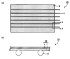
本開示の集電シート用樹脂フィルムについて図を用いて説明する。図1は本開示の集電シート用樹脂フィルムを例示する概略断面図である。図1に示す集電シート用樹脂フィルム10は、耐熱層1と、耐熱層1の一方の面側に配置された封止層2とを有し、耐熱層1は、ポリプロピレン樹脂を含有する。後述する図3(a)~(b)で説明するように、樹脂フィルム10は、ワイヤ11とともに集電シート20を構成する。また、後述する図6(a)~(c)で説明するように、樹脂フィルム10は、太陽電池素子31に電気的に接続されたワイヤ11を固定するために用いられる。 A resin film for a current collector sheet according to the present disclosure will be described with reference to the drawings. FIG. 1 is a schematic cross-sectional view illustrating a resin film for a current collector sheet according to the present disclosure. A
本開示によれば、耐熱層がポリプロピレン樹脂を含有することから、紫外線透過率および紫外線耐性が良好であり、集電シートに利用可能な剛性を有する樹脂フィルムとなる。さらに、集電シート用樹脂フィルムは剛性を有することから、集電シート用樹脂フィルムを用いて太陽電池素子にワイヤを固定する等の加熱工程において、集電シート用樹脂フィルムの熱収縮を抑え、カール変形を抑制できる。 According to the present disclosure, since the heat-resistant layer contains a polypropylene resin, the resin film has good ultraviolet transmittance and ultraviolet resistance, and has a rigidity that can be used as a current collector sheet. Furthermore, since the resin film for current collector sheets has rigidity, thermal shrinkage of the resin film for current collector sheets can be suppressed during heating processes such as fixing wires to solar cell elements using the resin film for current collector sheets. Curl deformation can be suppressed.
I.集電シート用樹脂フィルムの構成
本開示に用いられる集電シート用樹脂フィルムは、耐熱層と、封止層とを少なくとも有する。I. Configuration of resin film for current collector sheet The resin film for current collector sheet used in the present disclosure has at least a heat resistant layer and a sealing layer.
1.耐熱層
上記耐熱層は、集電シート用樹脂フィルムに耐熱性を付与する層である。ここで、「耐熱性」とは、集電シート用樹脂フィルムを用いて太陽電池素子にワイヤを固定する等の太陽電池の製造工程において加わる熱、および太陽電池の使用環境における熱に対する耐久性をいう。1. Heat-resistant layer The heat-resistant layer is a layer that imparts heat resistance to the resin film for current collector sheet. Here, "heat resistance" refers to the durability against heat applied in the manufacturing process of solar cells, such as fixing wires to solar cell elements using resin films for current collector sheets, and the heat in the environment in which solar cells are used. say.
(1)耐熱層の特性
本開示に用いられる耐熱層は、以下の特性を有することが好ましい。(1) Properties of heat-resistant layer The heat-resistant layer used in the present disclosure preferably has the following properties.
(a)融点
上記耐熱層を構成する樹脂の融点は、所望の耐熱性を示すことができれば特に限定されるものではないが、例えば、80℃以上であり、120℃以上であることが好ましく、150℃以上であることがより好ましい。また、耐熱層を構成する樹脂の融点の上限は、通常、200℃以下である。耐熱層を構成する樹脂の融点が低すぎる場合は太陽電池の製造工程中や太陽電池の使用中に集電シート用樹脂フィルムが著しく劣化する可能性があるからである。また、上記樹脂の融点が高すぎる場合は、フィルム状に成形することが困難となる可能性や、集電シート用樹脂フィルムの製造時において樹脂を融解するための温度を高くする必要があることから製造コストが増大する可能性があるからである。(a) Melting point The melting point of the resin constituting the heat-resistant layer is not particularly limited as long as it can exhibit the desired heat resistance, but is, for example, 80°C or higher, preferably 120°C or higher, More preferably, the temperature is 150°C or higher. Further, the upper limit of the melting point of the resin constituting the heat-resistant layer is usually 200° C. or lower. This is because if the melting point of the resin constituting the heat-resistant layer is too low, the resin film for the current collector sheet may deteriorate significantly during the manufacturing process of the solar cell or during the use of the solar cell. In addition, if the melting point of the resin is too high, it may be difficult to mold it into a film, or it may be necessary to increase the temperature for melting the resin when manufacturing the resin film for the current collector sheet. This is because manufacturing costs may increase.
本開示において、樹脂の融点は、プラスチックの転移温度測定方法(JIS K7121:1987)に準拠し、示差走査熱量分析(DSC)により行うことができる。なお、その際、融点ピークが2つ以上存在する場合は高い温度の方を融点とする。 In the present disclosure, the melting point of the resin can be determined by differential scanning calorimetry (DSC) in accordance with the plastic transition temperature measurement method (JIS K7121:1987). In addition, in that case, when two or more melting point peaks exist, the higher temperature is taken as the melting point.
(b)貯蔵弾性率
また、本開示の集電シート用樹脂フィルムは、太陽電池に用いられる際に集電シートとして太陽電池素子に密着して配置される。この際、集電シート用樹脂フィルムには、ワイヤを太陽電池素子に対して押し付けて電気的に接続させる程度の剛性を有することが好ましい。このような剛性は耐熱層により付与されるため、上記耐熱層は、所定の剛性を有することが好ましい。(b) Storage Modulus Furthermore, when the resin film for a current collector sheet of the present disclosure is used in a solar cell, it is placed in close contact with a solar cell element as a current collector sheet. At this time, it is preferable that the resin film for the current collector sheet has enough rigidity to press the wire against the solar cell element and electrically connect it. Since such rigidity is provided by the heat-resistant layer, it is preferable that the heat-resistant layer has a predetermined rigidity.
このような剛性は、例えば、貯蔵弾性率により評価することができる。上記耐熱層の150℃における貯蔵弾性率は、例えば、0.1MPa以上1.0GPa以下であり、1.0MPa以上100MPa以下であることが好ましい。上記範囲より上記貯蔵弾性率が小さい場合は、耐熱層の剛性が充分ではないことから、集電シート用樹脂フィルムとしての剛性も不十分となり、太陽電池素子に集電シートを配置した際に、ワイヤと太陽電池素子との接触が不十分となるといった不具合が生じる可能性がある。一方、上記範囲より上記貯蔵弾性率が大きい場合は、集電シートを太陽電池素子に配置する際に、大きな圧力を加える必要が生じ、製造装置の大型化等の不要なコストがかかるといった不具合が生じる可能性がある。 Such stiffness can be evaluated, for example, by storage modulus. The storage modulus of the heat-resistant layer at 150° C. is, for example, 0.1 MPa or more and 1.0 GPa or less, and preferably 1.0 MPa or more and 100 MPa or less. If the storage modulus is smaller than the above range, the heat-resistant layer will not have sufficient rigidity, and the resin film for the current collector sheet will also have insufficient rigidity, and when the current collector sheet is placed in the solar cell element, Problems such as insufficient contact between the wire and the solar cell element may occur. On the other hand, if the storage elastic modulus is larger than the above range, it will be necessary to apply a large amount of pressure when placing the current collector sheet on the solar cell element, which may cause problems such as increasing the size of the manufacturing equipment and other unnecessary costs. may occur.
ここで、貯蔵弾性率は、JIS K7244- 4:1999に準拠する方法により、動的粘弾性測定(DMA)により測定することができる。具体的には、まず、集電シート用樹脂フィルムを所望のサイズに切り出し、集電シート用樹脂フィルムから封止層を剥離して、または集電シート用樹脂フィルムから封止層を削り取って、耐熱層のサンプルを作製する。次に、引張方向がサンプルの長手方向となるように、動的粘弾性測定装置のチャックにサンプルの両端を取り付け、引張荷重をかけて、引張法で測定を行う。動的粘弾性測定装置としては、例えば、ユービーエム社製Rheogel-E4000を用いることができる。具体的な測定条件を下記に示す。 Here, the storage modulus can be measured by dynamic viscoelasticity measurement (DMA) according to a method based on JIS K7244-4:1999. Specifically, first, the resin film for the current collector sheet is cut out to a desired size, the sealing layer is peeled off from the resin film for the current collector sheet, or the sealing layer is scraped off from the resin film for the current collector sheet, Prepare a sample of the heat-resistant layer. Next, both ends of the sample are attached to the chuck of a dynamic viscoelasticity measuring device so that the tensile direction is the longitudinal direction of the sample, a tensile load is applied, and measurement is performed by the tensile method. As the dynamic viscoelasticity measuring device, for example, Rheogel-E4000 manufactured by UBM Corporation can be used. Specific measurement conditions are shown below.
(貯蔵弾性率の測定条件)
・測定試料:5mm×20mmの矩形
・測定モード:引張法(正弦波歪み、引張モード、歪み量:自動歪み)
・昇温速度:3℃/min
・温度:-60℃以上150℃以下
・周波数:10Hz
・引張荷重(静荷重):100g(Measurement conditions for storage modulus)
・Measurement sample: 5mm x 20mm rectangle ・Measurement mode: Tensile method (sine wave distortion, tensile mode, amount of distortion: automatic distortion)
・Temperature increase rate: 3℃/min
・Temperature: -60℃ or higher and 150℃ or lower ・Frequency: 10Hz
・Tensile load (static load): 100g
なお、耐熱層のサンプルの作製において、集電シート用樹脂フィルムから封止層を剥離するに際しては、例えば剥離試験機を用いてもよい。具体的には、所定のサイズの集電シート用樹脂フィルムを、耐熱層および封止層の界面に剥離のきっかけを付与した上で、剥離試験機に固定し、封止層を引っ張ることで、集電シート用樹脂フィルムから封止層を剥離することができる。 In addition, in preparing the sample of the heat-resistant layer, when peeling the sealing layer from the resin film for current collector sheet, for example, a peel tester may be used. Specifically, a resin film for a current collector sheet of a predetermined size is provided with a trigger for peeling at the interface between the heat-resistant layer and the sealing layer, and then fixed in a peel tester and the sealing layer is pulled. The sealing layer can be peeled off from the resin film for current collector sheet.
耐熱層の150℃における貯蔵弾性率は、例えば、耐熱層に含有されるポリプロピレン樹脂の種類、ポリプロピレン樹脂以外の材料の添加、材料組成等により調整することができる。例えば、フィラーを添加することにより、上記貯蔵弾性率を大きくすることができる。 The storage modulus of the heat-resistant layer at 150° C. can be adjusted by, for example, the type of polypropylene resin contained in the heat-resistant layer, addition of materials other than the polypropylene resin, material composition, etc. For example, the storage modulus can be increased by adding a filler.
(c)紫外線透過率
本開示における耐熱層は、上述したようにポリプロピレン樹脂を含有するものであり、従来のPET樹脂を用いたものより良好な紫外線透過率を有する。(c) Ultraviolet Transmittance The heat-resistant layer in the present disclosure contains polypropylene resin as described above, and has better ultraviolet transmittance than that using conventional PET resin.
上記耐熱層の紫外線透過率は、例えば波長350nmの光の透過率により評価できる。耐熱層の波長350nmの光の透過率としては、例えば、75%以上が好ましく、80%以上がより好ましく、85%以上がさらに好ましい。本開示に用いられる耐熱層の波長350nmの光の透過率が高いことにより、本開示の集電シート用樹脂フィルムを太陽電池素子に用いた場合に、紫外線領域を太陽電池素子の発電に寄与させることができる。 The ultraviolet transmittance of the heat-resistant layer can be evaluated, for example, by the transmittance of light at a wavelength of 350 nm. The transmittance of the heat-resistant layer for light having a wavelength of 350 nm is preferably 75% or more, more preferably 80% or more, and even more preferably 85% or more. Since the heat-resistant layer used in the present disclosure has high transmittance for light at a wavelength of 350 nm, when the resin film for current collector sheet of the present disclosure is used in a solar cell element, the ultraviolet region contributes to power generation of the solar cell element. be able to.
ここで、波長350nmの光の透過率は、例えば、分光光度計を用いて測定することができる。なお、耐熱層の波長350nmの光の透過率を測定するに際しては、測定用サンプルを作製し、測定に供する。測定用サンプルは、耐熱層の一方の面に、厚さ450μmのオレフィン樹脂を含有する封止材シート(大日本印刷社製「CVF2SS」)を積層し、設定温度150℃、真空引き5分、大気圧加圧9分、圧力100kPaの条件で真空ラミネートを行い、作製する。 Here, the transmittance of light with a wavelength of 350 nm can be measured using, for example, a spectrophotometer. In addition, when measuring the transmittance of light at a wavelength of 350 nm of the heat-resistant layer, a measurement sample is prepared and used for measurement. The measurement sample was prepared by laminating a 450 μm thick encapsulant sheet containing olefin resin (“CVF2SS” manufactured by Dai Nippon Printing Co., Ltd.) on one side of a heat-resistant layer, setting the temperature at 150°C, and vacuuming for 5 minutes. Vacuum lamination is performed under the conditions of atmospheric pressure pressurization for 9 minutes and pressure of 100 kPa.
(2)耐熱層の組成
本開示に用いられる耐熱層の組成は、ポリプロピレン樹脂を含有し、必要に応じて、光安定剤、封止層との密着性を向上させる密着性向上剤等が含有されていてもよい。(2) Composition of heat-resistant layer The composition of the heat-resistant layer used in the present disclosure contains polypropylene resin, and optionally contains a light stabilizer, an adhesion improver for improving adhesion with the sealing layer, etc. may have been done.
(a)ポリプロピレン樹脂
上記耐熱層は、少なくともポリプロピレン樹脂を含有する。(a) Polypropylene resin The heat-resistant layer contains at least polypropylene resin.
このようなポリプロピレン樹脂としては、例えば、プロピレン単独重合体であるホモポリプロピレン樹脂(ホモPP)であってもよく、プロピレンとα-オレフィンとのランダム共重合体であるランダムポリプロピレン樹脂(ランダムPP)であってもよく、ブロック共重合体であるブロックポリプロピレン樹脂(ブロックPP)であってもよい。上記耐熱層は、上述した各種ポリプロピレン樹脂の1種単独または2種以上含んでいてもよい。
本開示においては、中でも、ポリプロピレン樹脂がホモポリプロピレン樹脂であることが好ましい。ホモポリプロピレン樹脂は剛性が高いことから、集電シート用樹脂フィルムを用いて太陽電池素子に対しワイヤを固定しやすくすることができるからである。Such polypropylene resin may be, for example, homopolypropylene resin (homo PP), which is a propylene homopolymer, or random polypropylene resin (random PP), which is a random copolymer of propylene and α-olefin. It may be a block polypropylene resin (block PP) which is a block copolymer. The heat-resistant layer may contain one or more of the various polypropylene resins described above.
In the present disclosure, it is particularly preferable that the polypropylene resin is a homopolypropylene resin. This is because the homopolypropylene resin has high rigidity, so it is possible to easily fix the wire to the solar cell element using the resin film for the current collector sheet.
また、本開示における耐熱層は、樹脂としてポリプロピレン樹脂のみを含有していてもよく、ポリプロピレン樹脂を主成分とするように他の樹脂が含有されたものであってもよい。ここで、ポリプロピレン樹脂を主成分とするとは、全樹脂成分の中でもポリプロピレン樹脂の割合が最も多いことをいう。 Further, the heat-resistant layer in the present disclosure may contain only polypropylene resin as a resin, or may contain other resins such that polypropylene resin is the main component. Here, the expression "polypropylene resin is the main component" means that the proportion of polypropylene resin is the highest among all resin components.
上記耐熱層の全樹脂成分に対するポリプロピレン樹脂の割合は、例えば、50質量%以上であり、60質量%以上であってもよく、65質量%以上であってもよく、70質量%以上であってもよい。また、上記ポリプロピレン樹脂の割合は、100質量%以下であり、90質量%以下であってもよく、80質量%以下であってもよく、75質量%以下であってもよい。 The proportion of polypropylene resin to the total resin components of the heat-resistant layer is, for example, 50% by mass or more, may be 60% by mass or more, may be 65% by mass or more, and may be 70% by mass or more. Good too. Further, the proportion of the polypropylene resin is 100% by mass or less, may be 90% by mass or less, may be 80% by mass or less, and may be 75% by mass or less.
ポリプロピレン樹脂がホモポリプロピレン樹脂である場合、耐熱層の全樹脂成分に対するホモポリプロピレン樹脂の割合は、例えば、50質量%以上90質量%以下であることが好ましい。ホモポリプロピレン樹脂の割合が少なすぎると、集電シート用樹脂フィルムに対し所望の耐熱性を付与することが困難となるからである。一方、ホモポリプロピレン樹脂は例えばランダムポリプロピレン樹脂と比較して透明性に劣るため、ホモポリプロピレン樹脂の割合が多すぎると、集電シート用樹脂フィルムの透明性が低下する可能性があるからである。 When the polypropylene resin is a homopolypropylene resin, the ratio of the homopolypropylene resin to the total resin components of the heat-resistant layer is preferably, for example, 50% by mass or more and 90% by mass or less. This is because if the proportion of the homopolypropylene resin is too small, it will be difficult to impart desired heat resistance to the resin film for current collector sheet. On the other hand, since homopolypropylene resin has inferior transparency compared to, for example, random polypropylene resin, if the proportion of homopolypropylene resin is too large, the transparency of the resin film for the current collector sheet may decrease.
なお、集電シート用樹脂フィルムの各層に含有される各樹脂成分の割合は、例えば、示査走査熱量測定(DSC)、赤外分光法(IR)、核磁気共鳴(NMR)で検出されるピーク比等から分析することができる。 The proportion of each resin component contained in each layer of the resin film for current collector sheet is detected by, for example, differential scanning calorimetry (DSC), infrared spectroscopy (IR), or nuclear magnetic resonance (NMR). It can be analyzed based on peak ratio etc.
(b)光安定剤
本開示における耐熱層は、光安定剤を含有していてもよい。耐熱層が光安定剤を含有することで、耐熱層の紫外線劣化をより抑制できるからである。光安定剤としては、例えば、ヒンダードアミン系光安定剤(HALS)を用いることが好ましい。(b) Light stabilizer The heat-resistant layer in the present disclosure may contain a light stabilizer. This is because the heat-resistant layer containing the light stabilizer can further suppress UV deterioration of the heat-resistant layer. As the light stabilizer, it is preferable to use, for example, a hindered amine light stabilizer (HALS).
ヒンダードアミン系光安定剤としては、光安定作用を発揮できれば特に限定されないが、例えばエチレンと環状アミノビニル化合物(ヒンダードアミン系アクリレート)との共重合体であり、分子量が30000以上の分子構造を有する、高分子量タイプの光安定剤を好適に用いることができる。 The hindered amine light stabilizer is not particularly limited as long as it can exhibit a light stabilizing effect, but for example, it is a copolymer of ethylene and a cyclic aminovinyl compound (hindered amine acrylate), and a polymer having a molecular structure with a molecular weight of 30,000 or more. Molecular weight type light stabilizers can be suitably used.
高分子量タイプの光安定剤の具体例としては、エチレンと、下記化学式(1)で表される環状アミノビニル化合物(ヒンダードアミン系アクリレート)との共重合体が挙げられる。 A specific example of a high molecular weight type light stabilizer is a copolymer of ethylene and a cyclic aminovinyl compound (hindered amine acrylate) represented by the following chemical formula (1).

高分子量タイプのヒンダードアミン系光安定剤の具体例としては、例えば、日本ポリエチレン株式会社製の「XJ-100H(商品名)」(分子量:35000)を挙げることができる。 A specific example of a high molecular weight type hindered amine light stabilizer is "XJ-100H (trade name)" (molecular weight: 35,000) manufactured by Japan Polyethylene Co., Ltd., for example.
また、ヒンダードアミン系光安定剤の他の例としては、NOR型のヒンダードアミン系光安定剤を挙げることができる。NOR型ヒンダードアミン系光安定剤の一例としては、一般式(1)で表される基を含む化合物が挙げられる。 Other examples of hindered amine light stabilizers include NOR type hindered amine light stabilizers. An example of the NOR type hindered amine light stabilizer includes a compound containing a group represented by general formula (1).

一般式(1)において、Rは置換または非置換の炭化水素基またはアシル基である。Rとしては、例えば、アルキル基、アルケニル基、アルキレン基、シクロアルキル基、ビシクロアルキル基、フェニル基、ナフチル基、フェニルアルキル基、アルキル基置換フェニル基、水酸基置換アルキル基、アシル基、アルコキシ置換アルキル基、チオアルコキシ基置換アルキル基等が挙げられる。なお、一般式(1)における*および**は、他の元素と結合可能な状態を示している。 In general formula (1), R is a substituted or unsubstituted hydrocarbon group or acyl group. Examples of R include an alkyl group, an alkenyl group, an alkylene group, a cycloalkyl group, a bicycloalkyl group, a phenyl group, a naphthyl group, a phenylalkyl group, an alkyl-substituted phenyl group, a hydroxyl-substituted alkyl group, an acyl group, and an alkoxy-substituted alkyl group. group, a thioalkoxy group-substituted alkyl group, and the like. Note that * and ** in general formula (1) indicate a state in which it is possible to combine with other elements.
NOR型ヒンダードアミン系光安定剤の他の例としては、一般式(2)または一般式(3)で表される化合物が挙げられる。 Other examples of NOR type hindered amine light stabilizers include compounds represented by general formula (2) or general formula (3).

一般式(2)において、R1およびR2は、それぞれ独立に、上述した一般式(1)におけるRと同様に、置換または非置換の炭化水素基またはアシル基である。中でも、R1およびR2は、それぞれ独立に、炭素数4以上20以下のアルキル基であることが好ましい。In general formula (2), R 1 and R 2 are each independently a substituted or unsubstituted hydrocarbon group or acyl group, similar to R in general formula (1) described above. Among these, R 1 and R 2 are preferably each independently an alkyl group having 4 or more and 20 or less carbon atoms.
一般式(3)において、R3およびR4は、それぞれ独立に、上述した一般式(1)におけるRと同様に、置換または非置換の炭化水素基またはアシル基である。中でも、R3およびR4は、それぞれ独立に、炭素数4以上20以下のアルキル基であることが好ましい。また、R5は、炭素数1以上8以下のアルキレン基である。In general formula (3), R 3 and R 4 are each independently a substituted or unsubstituted hydrocarbon group or acyl group, similar to R in general formula (1) described above. Among these, R 3 and R 4 are preferably each independently an alkyl group having 4 or more and 20 or less carbon atoms. Further, R 5 is an alkylene group having 1 or more and 8 or less carbon atoms.
NOR型ヒンダードアミン系光安定剤の具体例としては、例えば、アデカ社製の「アデカスタブLA-81(商品名)」、BASF社製の「チヌビン123(商品名)」(デカン二酸ビス(2,2,6,6-テトラメチル-1-(オクチルオキシ)-4-ピペリジニル)エステル)、BASF社製の「チヌビンXT850FF(商品名)」等が挙げられる。 Specific examples of NOR-type hindered amine light stabilizers include "Adekastab LA-81 (trade name)" manufactured by Adeka, "Tinuvin 123 (trade name)" manufactured by BASF (decanedioic acid bis(2, 2,6,6-tetramethyl-1-(octyloxy)-4-piperidinyl) ester) and "Tinuvin XT850FF (trade name)" manufactured by BASF.
耐熱層の全固形分に対する光安定剤の割合は、例えば、3質量%以上10質量%以下であり、3.5質量%以上4.5質量%以下であることが好ましい。光安定剤の割合を上記範囲内とすることにより、集電シート用樹脂フィルムの紫外線耐性をより良好にすることができる。一方、上記光安定剤の割合が多すぎると、光安定剤のブリードアウトにより耐熱層の透明性が低下する可能性や、耐熱層および封止層の間の密着性が低下する可能性があるからである。 The ratio of the light stabilizer to the total solid content of the heat-resistant layer is, for example, 3% by mass or more and 10% by mass or less, and preferably 3.5% by mass or more and 4.5% by mass or less. By controlling the proportion of the light stabilizer within the above range, the ultraviolet resistance of the resin film for current collector sheet can be improved. On the other hand, if the proportion of the light stabilizer is too high, the transparency of the heat-resistant layer may be reduced due to bleed-out of the light stabilizer, or the adhesion between the heat-resistant layer and the sealing layer may be reduced. It is from.
(c)密着性向上剤
本開示における耐熱層は、上記封止層との密着性、特に封止層がポリエチレン樹脂を含有する場合の密着性を向上させるために、密着性向上剤を含有してもよい。(c) Adhesion improver The heat-resistant layer in the present disclosure contains an adhesion improver in order to improve the adhesion with the sealing layer, especially when the sealing layer contains a polyethylene resin. It's okay.
このような密着性向上剤としては、例えば、ポリエチレン系エラストマーやポリエチレン系プラストマー等を挙げることができる。本開示においては、ポリエチレン系エラストマーやポリエチレン系プラストマーを耐熱層に含有させることにより、封止層との密着性を向上させるばかりでなく、集電シート用樹脂フィルムの耐久性を向上させることができる。 Examples of such adhesion improvers include polyethylene elastomers and polyethylene plastomers. In the present disclosure, by containing a polyethylene elastomer or a polyethylene plastomer in the heat-resistant layer, it is possible to not only improve the adhesion with the sealing layer but also improve the durability of the resin film for the current collector sheet. .
ポリエチレン系エラストマーおよびポリエチレン系プラストマーとしては、例えば、エチレンとエチレン以外のα-オレフィンとの共重合体(以下、エチレン-α-オレフィン共重合体と称する場合がある。)を挙げることができる。 Examples of polyethylene elastomers and polyethylene plastomers include copolymers of ethylene and α-olefins other than ethylene (hereinafter sometimes referred to as ethylene-α-olefin copolymers).
エチレン-α-オレフィン共重合体を構成するポリエチレンとしては、特に限定されないが、低密度ポリエチレンであることが好ましい。また、低密度ポリエチレンとしては、例えば、密度0.870g/cm3以上0.910g/cm3以下の低密度ポリエチレンであることが好ましい。ポリエチレンの密度は、JIS K7112:1999に準拠した方法で測定することができる。The polyethylene constituting the ethylene-α-olefin copolymer is not particularly limited, but low density polyethylene is preferable. Further, as the low-density polyethylene, for example, it is preferable to use a low-density polyethylene having a density of 0.870 g/cm 3 or more and 0.910 g/cm 3 or less. The density of polyethylene can be measured by a method based on JIS K7112:1999.
エチレン-α-オレフィン共重合体を構成するα-オレフィンとしては、例えば、炭素数3以上20以下のα-オレフィンが挙げられる。具体的には、プロピレン、1-ブテン、4-メチル-1-ペンテン、3-メチル-1-ブテン、1-ペンテン、1-ヘキセン、1-ヘプテン、1-オクテン、1-ノネン、1-デセン、1-ウンデセン、1-ドデセン等が挙げられる。これらは1種または2種以上が用いられる。 Examples of the α-olefin constituting the ethylene-α-olefin copolymer include α-olefins having 3 or more and 20 or less carbon atoms. Specifically, propylene, 1-butene, 4-methyl-1-pentene, 3-methyl-1-butene, 1-pentene, 1-hexene, 1-heptene, 1-octene, 1-nonene, 1-decene. , 1-undecene, 1-dodecene and the like. These may be used alone or in combination of two or more.
エチレン-α-オレフィン共重合体は、例えば、市販製品を用いてもよい。市販製品としては、例えば、三井化学社製の「タフマーDF-710(商品名)」、「タフマーDF-119(商品名)」、「タフマーDF-110(商品名)」、「タフマーA-1085S(商品名)」、「タフマーA-4070S(商品名)」、「タフマーA-4085S(商品名)」、「タフマーA-4090S(商品名)」を挙げることができる。また、日本ポリエチレン社製の「カーネルKF260T(商品名)」、「カーネルKF270(商品名)」、「カーネルKF370(商品名)」、「カーネルKF360T(商品名)」、「カーネルKS240T(商品名)」、「カーネルKS340T(商品名)」、「カーネルKS260(商品名)」を挙げることができる。さらにまた、住友化学社製の「エクセレンVL100(商品名)」、「エクセレンVL102(商品名)」、「エクセレンVL200(商品名)」、「エクセレンFX201(商品名)」、「エクセレンFX301(商品名)」、「エクセレンFX307(商品名)」、「エクセレンFX351(商品名)」、「エクセレンFX352(商品名)」、「エクセレンFX357(商品名)」を挙げることができる。 As the ethylene-α-olefin copolymer, for example, a commercially available product may be used. Commercially available products include, for example, "Tafmer DF-710 (product name)", "Tafmer DF-119 (product name)", "Tafmer DF-110 (product name)", and "Tafmer A-1085S" manufactured by Mitsui Chemicals. (trade name)," "Tafmer A-4070S (trade name)," "Tafmer A-4085S (trade name)," and "Tafmer A-4090S (trade name)." In addition, "Kernel KF260T (product name)", "Kernel KF270 (product name)", "Kernel KF370 (product name)", "Kernel KF360T (product name)", "Kernel KS240T (product name)" manufactured by Japan Polyethylene Co., Ltd. ”, “Kernel KS340T (product name)”, and “Kernel KS260 (product name)”. Furthermore, "Excellen VL100 (product name)", "Excellen VL102 (product name)", "Excellen VL200 (product name)", "Excellen FX201 (product name)", "Excellen FX301 (product name)" manufactured by Sumitomo Chemical Co., Ltd. )," "Excellen FX307 (product name)," "Excellen FX351 (product name)," "Excellen FX352 (product name)," and "Excellen FX357 (product name)."
耐熱層の全樹脂成分に対する、密着性向上剤の割合は、例えば、5質量%以上であり、10質量%以上であってもよく、15質量%以上であってもよい。また、上記密着性向上剤の割合は、例えば、50質量%未満であり、40質量%以下であってもよく、30質量%以下であってもよく、20質量%以下であってもよい。密着性向上剤の割合が多すぎると、集電シート用樹脂フィルムの透明性が低下する可能性があるからである。また、集電シート用樹脂フィルムが所望の耐熱性を有することが出来なくなる可能性があるからである。 The proportion of the adhesion improver to the total resin components of the heat-resistant layer is, for example, 5% by mass or more, may be 10% by mass or more, or may be 15% by mass or more. Further, the proportion of the adhesion improver is, for example, less than 50% by mass, may be 40% by mass or less, may be 30% by mass or less, or may be 20% by mass or less. This is because if the proportion of the adhesion improver is too high, the transparency of the resin film for current collector sheet may decrease. In addition, there is a possibility that the resin film for the current collector sheet will not have the desired heat resistance.
(d)その他
本開示おける耐熱層は、ポリプロピレン系エラストマー(PP系エラストマー)を含有していてもよい。上記耐熱層は、ポリプロピレン系エラストマーを含有することにより、耐熱層の透明性を高くすることができる。(d) Others The heat-resistant layer in the present disclosure may contain a polypropylene elastomer (PP elastomer). By containing the polypropylene-based elastomer, the heat-resistant layer can have high transparency.
ポリプロピレン系エラストマーとしては、例えば、プロピレンとプロピレン以外のα-オレフィンとの共重合体(以下、プロピレン-α-オレフィン共重合体と称する場合がある。)を挙げることができる。 Examples of polypropylene elastomers include copolymers of propylene and α-olefins other than propylene (hereinafter sometimes referred to as propylene-α-olefin copolymers).
プロピレン-α-オレフィン共重合体を構成するα-オレフィンとしては、例えば、炭素数2または4以上20以下のα-オレフィンが挙げられる。具体的には、エチレン、1-ブテン、4-メチル-1-ペンテン、1-ペンテン、1-ヘキセン、1-ヘプテン、1-オクテン、1-デセン、1-ドデセン、1-テトラデセン、1-ヘキサデセン、1-オクタデセン、1-エイコセン等が挙げられる。これらは1種または2種以上が用いられる。 Examples of the α-olefin constituting the propylene-α-olefin copolymer include α-olefins having 2 or more than 4 carbon atoms and 20 or less carbon atoms. Specifically, ethylene, 1-butene, 4-methyl-1-pentene, 1-pentene, 1-hexene, 1-heptene, 1-octene, 1-decene, 1-dodecene, 1-tetradecene, 1-hexadecene. , 1-octadecene, 1-eicosene and the like. These may be used alone or in combination of two or more.
プロピレン-α-オレフィン共重合体は、中でも、プロピレンとエチレンとプロピレンおよびエチレン以外のα-オレフィンとの共重合体であることが好ましい。 The propylene-α-olefin copolymer is preferably a copolymer of propylene, ethylene, and an α-olefin other than propylene and ethylene.
プロピレン-α-オレフィン共重合体は、例えば、市販製品を用いてもよい。市販製品としては、例えば、三井化学社製のタフマーPN-3560(商品名)、タフマーPN-0040(商品名)、及びタフマーPN-2060(商品名)を挙げることができる。 As the propylene-α-olefin copolymer, for example, a commercially available product may be used. Examples of commercially available products include Tafmer PN-3560 (trade name), Tafmer PN-0040 (trade name), and Tafmer PN-2060 (trade name) manufactured by Mitsui Chemicals.
耐熱層の全樹脂成分に対する、ポリプロピレン系エラストマーの割合は、例えば、5質量%以上であり、10質量%以上であってもよく、15質量%以上であってもよい。また、上記ポリプロピレン系エラストマーの割合は、例えば、50質量%未満であり、40質量%以下であってもよく、30質量%以下であってもよく、20質量%以下であってもよい。ポリプロピレン系エラストマーの割合が上記範囲より小さい場合は、集電シート用樹脂フィルムの透明性の向上の効果が得られない可能性があるからである。また、ポリプロピレン系エラストマーの割合が上記範囲を超える場合は、集電シート用樹脂フィルムが所望の耐熱性を有することが出来なくなる可能性があるからである。 The proportion of the polypropylene elastomer to the total resin components of the heat-resistant layer is, for example, 5% by mass or more, may be 10% by mass or more, or may be 15% by mass or more. Further, the proportion of the polypropylene elastomer is, for example, less than 50% by mass, may be 40% by mass or less, may be 30% by mass or less, or may be 20% by mass or less. This is because if the proportion of the polypropylene elastomer is smaller than the above range, the effect of improving the transparency of the resin film for current collector sheet may not be obtained. Furthermore, if the proportion of the polypropylene elastomer exceeds the above range, the resin film for current collector sheet may not have the desired heat resistance.
(3)その他
上記耐熱層の厚さは、集電シート用樹脂フィルムが用いられる太陽電池の大きさ、用途に応じて適宜選択することができ、特に限定されないが、例えば、10μm以上であり、15μm以上であってもよく、20μm以上であってもよい。また、耐熱層の厚さは、例えば、50μm以下であり、45μm以下であってもよく、40μm以下であってもよい。(3) Others The thickness of the heat-resistant layer can be appropriately selected depending on the size and purpose of the solar cell in which the resin film for current collector sheet is used, and is not particularly limited, but is, for example, 10 μm or more, The thickness may be 15 μm or more, or 20 μm or more. Moreover, the thickness of the heat-resistant layer is, for example, 50 μm or less, may be 45 μm or less, or may be 40 μm or less.
2.封止層
本開示における封止層は、熱溶着性を有し、集電シートに用いた際にワイヤを支持する層である。2. Sealing Layer The sealing layer in the present disclosure is a layer that has thermal weldability and supports a wire when used in a current collector sheet.
上記封止層に用いられる樹脂は、通常、熱溶着性を有する樹脂である。また、封止層に用いられる樹脂としては、集電シートを太陽電池素子に熱圧着した際にワイヤの周囲に回りこむ性質を有することが好ましい。以下、上述の性質をモールディング性と称して説明する場合がある。 The resin used for the sealing layer is usually a resin that has thermal weldability. Further, the resin used for the sealing layer preferably has a property of wrapping around the wire when the current collecting sheet is thermocompression bonded to the solar cell element. Hereinafter, the above-mentioned property may be referred to as moldability and explained.
上記封止層は、上記耐熱層に対する密着性と、金属材料であるワイヤに対する密着性とを必要とする。このような封止層は、単層で構成されていてもよく、多層で構成されていてもよい。以下、封止層が単層である場合と、封止層が多層である場合とに分けて説明する。 The sealing layer requires adhesion to the heat-resistant layer and to the wire, which is a metal material. Such a sealing layer may be comprised of a single layer or may be comprised of multiple layers. Hereinafter, a case where the sealing layer is a single layer and a case where the sealing layer is a multilayer will be explained separately.
(1)封止層が単層である場合
封止層が単層である場合、封止層は、通常、熱溶着性およびモールディング性を有する樹脂を含有する。このような樹脂としては、例えば、熱可塑性樹脂を挙げることができる。熱可塑性樹脂としては、紫外線透過率や可視光線透過率等を考慮すると、ポリオレフィン樹脂、およびアイオノマー樹脂を用いることが好ましい。本開示においては、なかでも、ポリオレフィン樹脂であることが好ましい。以下、ポリオレフィン樹脂の詳細を説明する。(1) When the sealing layer is a single layer When the sealing layer is a single layer, the sealing layer usually contains a resin having heat-weldability and moldability. Examples of such resins include thermoplastic resins. As the thermoplastic resin, polyolefin resins and ionomer resins are preferably used in consideration of ultraviolet transmittance, visible light transmittance, and the like. In the present disclosure, polyolefin resins are particularly preferred. The details of the polyolefin resin will be explained below.
(a)ポリオレフィン樹脂
封止層に用いられるポリオレフィン樹脂の融点は、所望の熱溶着性およびモールディング性を示すことができれば特に限定されない。ポリオレフィン樹脂の融点は、例えば、125℃以下であり、120℃以下であってもよく、110℃以下であってもよい。また、ポリオレフィン樹脂の融点は、例えば、80℃以上である。ポリオレフィン樹脂の融点が高すぎる場合は集電シートを太陽電池素子に熱圧着する際の温度を高くする必要があることから、製造コストが増大したり、太陽電池素子が劣化したりする可能性があるからである。一方、ポリオレフィン樹脂の融点が低すぎる場合は太陽電池の使用環境において封止層が融解し、ワイヤを固定することが困難となる可能性があるからである。(a) Polyolefin Resin The melting point of the polyolefin resin used in the sealing layer is not particularly limited as long as it can exhibit desired thermal weldability and moldability. The melting point of the polyolefin resin is, for example, 125°C or lower, may be 120°C or lower, or may be 110°C or lower. Further, the melting point of the polyolefin resin is, for example, 80° C. or higher. If the melting point of the polyolefin resin is too high, it will be necessary to raise the temperature when thermocompression bonding the current collector sheet to the solar cell element, which may increase manufacturing costs or cause the solar cell element to deteriorate. Because there is. On the other hand, if the melting point of the polyolefin resin is too low, the sealing layer may melt in the environment in which the solar cell is used, making it difficult to fix the wire.
本開示においては、上記ポリオレフィン樹脂の中でも、ポリエチレン樹脂、ポリプロピレン樹脂が好ましく、特にポリエチレン樹脂であることが好ましい。モールディング性に優れるためである。 In the present disclosure, among the above polyolefin resins, polyethylene resins and polypropylene resins are preferred, and polyethylene resins are particularly preferred. This is because it has excellent moldability.
ポリエチレン樹脂としては、例えば、高密度ポリエチレン(HDPE)、直鎖状低密度ポリエチレン(LLDPE)、低密度ポリエチレン(LDPE)、超低密度ポリエチレン(VLDPE)等が挙げられる。これらは単独で用いてもよいし、2種以上併用してもよい。本開示においては、中でも直鎖状低密度ポリエチレン(LLDPE)であることが好ましい。耐熱層と封止層との密着性を良好にすることができるからである。 Examples of the polyethylene resin include high density polyethylene (HDPE), linear low density polyethylene (LLDPE), low density polyethylene (LDPE), and very low density polyethylene (VLDPE). These may be used alone or in combination of two or more. In the present disclosure, linear low density polyethylene (LLDPE) is particularly preferred. This is because the adhesion between the heat-resistant layer and the sealing layer can be improved.
ポリエチレン樹脂の密度は、特に限定されないが、例えば、0.890g/cm3以上0.930g/cm3以下であることが好ましく、0.900g/cm3以上0.925g/cm3以下であることがより好ましい。ポリエチレン樹脂の密度は、JIS K7112:1999に準拠したピクノメーター法により測定することができる。The density of the polyethylene resin is not particularly limited, but for example, it is preferably 0.890 g/cm 3 or more and 0.930 g/cm 3 or less, and 0.900 g/cm 3 or more and 0.925 g/cm 3 or less. is more preferable. The density of polyethylene resin can be measured by a pycnometer method based on JIS K7112:1999.
また、封止層は、ポリオレフィン樹脂として、上述したポリエチレン系エラストマーやポリエチレン系プラストマーを含有していることが好ましい。 Moreover, it is preferable that the sealing layer contains the above-mentioned polyethylene elastomer or polyethylene plastomer as the polyolefin resin.
封止層は、上述したポリオレフィン樹脂のみを含有していてもよく、ポリオレフィン樹脂に加えてポリオレフィン樹脂以外の樹脂をさらに含有していてもよい。後者の場合、封止層はポリオレフィン樹脂を主成分として含有することが好ましい。ポリオレフィン樹脂を主成分とするとは、全樹脂成分の中でもポリプロピレン樹脂の割合が最も多いことをいう。 The sealing layer may contain only the polyolefin resin described above, or may further contain a resin other than the polyolefin resin in addition to the polyolefin resin. In the latter case, the sealing layer preferably contains polyolefin resin as a main component. The phrase "polyolefin resin is the main component" means that the proportion of polypropylene resin is the highest among all resin components.
封止層中の全樹脂成分に対するポリオレフィン樹脂の割合は、例えば、50質量%以上であり、60質量%以上であってもよく、70質量%以上であってもよい。また、上記ポリオレフィン樹脂の割合は、例えば、99質量%以下であり、95質量%以下であってもよく、90質量%以下であってもよい。上記ポリオレフィン樹脂の割合は、100質量%であってもよい。 The ratio of the polyolefin resin to all resin components in the sealing layer is, for example, 50% by mass or more, may be 60% by mass or more, or may be 70% by mass or more. Further, the proportion of the polyolefin resin may be, for example, 99% by mass or less, 95% by mass or less, or 90% by mass or less. The proportion of the polyolefin resin may be 100% by mass.
また、ポリオレフィン樹脂として、上述したポリエチレン系エラストマーやポリエチレン系プラストマーを含有する場合、封止層中の全樹脂成分に対するポリオレフィン樹脂の割合は、例えば、90質量%以上100質量%以下であることが好ましい。耐熱層と封止層との密着性を特に良好にすることができ、耐久性に優れた集電シート用樹脂フィルムとすることができるからである。また、集電シート用樹脂フィルムを用いて太陽電池素子にワイヤを固定する等の加熱工程において、集電シート用樹脂フィルムの熱収縮を抑え、カール変形を抑制できるからである。 Further, when the polyolefin resin contains the above-mentioned polyethylene elastomer or polyethylene plastomer, the proportion of the polyolefin resin to the total resin components in the sealing layer is preferably, for example, 90% by mass or more and 100% by mass or less. . This is because the adhesion between the heat-resistant layer and the sealing layer can be particularly improved, and a resin film for a current collector sheet with excellent durability can be obtained. Moreover, in a heating step such as fixing a wire to a solar cell element using a resin film for a current collector sheet, thermal shrinkage of the resin film for a current collector sheet can be suppressed and curl deformation can be suppressed.
(b)光安定剤
本開示における封止層は、熱可塑性樹脂を含有していれば特に限定されず、必要に応じてその他の成分を適宜選択して追加できる。このような成分としては、例えば、光安定剤を挙げることができる。光安定剤としては、上述した「1.耐熱層 (2)耐熱層の組成
(b)光安定剤」の項で説明した内容と同様であるため、ここでの説明は省略する。(b) Light stabilizer The sealing layer in the present disclosure is not particularly limited as long as it contains a thermoplastic resin, and other components can be appropriately selected and added as necessary. Examples of such components include light stabilizers. Since the light stabilizer is the same as that explained in the above section "1. Heat-resistant layer (2) Composition of heat-resistant layer (b) Light stabilizer", the explanation here will be omitted.
封止層の全固形成分に対する、光安定剤の割合は、例えば、0.2質量%以上5質量%以下であり、0.5質量%以上3質量%以下であることが好ましい。 The ratio of the light stabilizer to the total solid components of the sealing layer is, for example, 0.2% by mass or more and 5% by mass or less, and preferably 0.5% by mass or more and 3% by mass or less.
(c)接着性向上剤
また、本開示における封止層は、ワイヤや太陽電池素子との接着性を向上させる成分を含有するものであってもよい。(c) Adhesiveness Improver Furthermore, the sealing layer in the present disclosure may contain a component that improves adhesiveness with wires and solar cell elements.
このような成分としては、例えば、シラン変性ポリエチレン樹脂が挙げられる。シラン変性ポリエチレン樹脂は、α-オレフィンとエチレン性不飽和シラン化合物とがコモノマーとして共重合されたシラン共重合体である。本開示においては、シラン変性ポリエチレン樹脂として、主鎖として直鎖状低密度ポリエチレン(LLDPE)にエチレン性不飽和シラン化合物を側鎖としてグラフト重合させた樹脂であることが好ましい。 Examples of such components include silane-modified polyethylene resins. The silane-modified polyethylene resin is a silane copolymer in which an α-olefin and an ethylenically unsaturated silane compound are copolymerized as comonomers. In the present disclosure, the silane-modified polyethylene resin is preferably a resin obtained by graft polymerizing an ethylenically unsaturated silane compound as a side chain to linear low density polyethylene (LLDPE) as a main chain.
エチレン性不飽和シラン化合物としては、例えば、ビニルトリメトキシシラン、ビニルトリエトキシシラン、ビニルトリプロポキシシラン、ビニルトリイソプロポキシシラン、ビニルトリブトキシシラン、ビニルトリペンチロキシシラン、ビニルトリフェノキシシラン、ビニルトリベンジルオキシシラン、ビニルトリメチレンジオキシシラン、ビニルトリエチレンジオキシシラン、ビニルプロピオニルオキシシラン、ビニルトリアセトキシシラン、ビニルトリカルボキシシランを挙げることができる。 Examples of ethylenically unsaturated silane compounds include vinyltrimethoxysilane, vinyltriethoxysilane, vinyltripropoxysilane, vinyltriisopropoxysilane, vinyltributoxysilane, vinyltripentyloxysilane, vinyltriphenoxysilane, and vinyltripropoxysilane. Examples include benzyloxysilane, vinyltrimethylenedioxysilane, vinyltriethylenedioxysilane, vinylpropionyloxysilane, vinyltriacetoxysilane, and vinyltricarboxysilane.
シラン変性ポリエチレン樹脂は、例えば、特開2003-46105号公報に記載されている製造方法により得ることができる。 The silane-modified polyethylene resin can be obtained, for example, by the manufacturing method described in JP-A No. 2003-46105.
封止層の全樹脂成分に対する、シラン変性ポリエチレン樹脂の割合は、特に限定されないが、例えば、5質量%以上25質量%以下が好ましい。また、エチレン性不飽和シラン化合物の含量であるグラフト量としては、例えば、封止層の全樹脂成分100重量部に対して、0.001重量部以上15重量部以下が好ましい。 The ratio of the silane-modified polyethylene resin to the total resin components of the sealing layer is not particularly limited, but is preferably, for example, 5% by mass or more and 25% by mass or less. Further, the amount of grafting, which is the content of the ethylenically unsaturated silane compound, is preferably 0.001 parts by weight or more and 15 parts by weight or less, for example, based on 100 parts by weight of the total resin components of the sealing layer.
(2)封止層が多層である場合
上記封止層は、複数の樹脂層が積層された多層であってもよい。封止層が多層である場合、例えば、図2に示すように、封止層2は、耐熱層1側の面側に配置された基材層2aと、基材層2aの耐熱層1とは反対側の面側に配置された接着層2bとを有することが好ましい。(2) When the sealing layer is multilayer The sealing layer may be a multilayer in which a plurality of resin layers are laminated. When the sealing layer is multi-layered, for example, as shown in FIG. preferably has an adhesive layer 2b disposed on the opposite surface side.
本開示においては、上記接着層に上述した接着性向上剤を添加することが好ましい。接着層中に、上述した接着性向上剤を添加することで、上記接着性向上剤の使用量と少なくすることができるため、集電シート用樹脂フィルムの製造コストを抑えることができるからである。 In the present disclosure, it is preferable to add the adhesion improver described above to the adhesive layer. This is because by adding the above-mentioned adhesion improver to the adhesive layer, the amount of use of the above-mentioned adhesion improver can be reduced, thereby reducing the manufacturing cost of the resin film for the current collector sheet. .
基材層および接着層に用いられる樹脂および任意の成分については、上述した「(1)封止層が単層である場合」の項で説明した内容と同様とすることができるため、ここでの説明は省略する。 The resin and optional components used in the base material layer and the adhesive layer can be the same as those explained in the above section "(1) When the sealing layer is a single layer", so they will be described here. The explanation of is omitted.
(3)その他
本開示における封止層の厚さとしては、集電シートとした際にワイヤを支持することができれば特に限定されず、ワイヤの太さに応じて適宜選択することができる。封止層の厚さとしては、例えば、10μm以上であり、20μm以上であってもよく、50μm以上であってもよく、65μm以上であってもよい。また、耐熱層の厚さは、例えば、170μm以下であり、100μm以下であってもよく、45μm以下であってもよく、40μm以下であってもよい。(3) Others The thickness of the sealing layer in the present disclosure is not particularly limited as long as it can support the wire when used as a current collector sheet, and can be appropriately selected depending on the thickness of the wire. The thickness of the sealing layer may be, for example, 10 μm or more, 20 μm or more, 50 μm or more, or 65 μm or more. Further, the thickness of the heat-resistant layer may be, for example, 170 μm or less, 100 μm or less, 45 μm or less, or 40 μm or less.
3.中間層
本開示の集電シート用樹脂フィルムは、耐熱層および封止層の間に中間層が配置されていてもよい。中間層としては、例えば、耐熱層および封止層を貼り合わせる接着剤を含有する接着剤層が挙げられる。接着剤としては、一般的なフィルムの貼り合わせに用いられる接着剤を挙げることができる。中間層の厚さは、集電シート用樹脂フィルムの透明性を過度に妨げない程度であれば特に限定されない。3. Intermediate Layer In the resin film for current collector sheet of the present disclosure, an intermediate layer may be disposed between the heat-resistant layer and the sealing layer. Examples of the intermediate layer include an adhesive layer containing an adhesive for bonding the heat-resistant layer and the sealing layer. Examples of the adhesive include adhesives commonly used for bonding films together. The thickness of the intermediate layer is not particularly limited as long as it does not excessively impede the transparency of the resin film for current collector sheet.
また、上記耐熱層がポリプロピレン樹脂を有し、上記封止層がポリエチレン樹脂を有する場合は、中間層として、ポリプロピレン樹脂およびポリエチレン樹脂を混合した組成からなる層を設けてもよい。 Further, when the heat-resistant layer has a polypropylene resin and the sealing layer has a polyethylene resin, a layer made of a mixture of a polypropylene resin and a polyethylene resin may be provided as an intermediate layer.
4.その他
上記耐熱層および上記封止層の層間密着強度は、例えば、1.0N/15mm以上であることが好ましく、2.0N/15mm以上であることがより好ましく、5.0N/15mm以上であることがさらに好ましい。層間密着度が上記値以上であることにより、耐熱層および封止層間の密着性を良好にすることができ、両者の剥離を効果的に抑制できるからである。4. Others The interlayer adhesion strength of the heat-resistant layer and the sealing layer is, for example, preferably 1.0 N/15 mm or more, more preferably 2.0 N/15 mm or more, and 5.0 N/15 mm or more. It is even more preferable. This is because when the degree of interlayer adhesion is equal to or higher than the above value, the adhesion between the heat-resistant layer and the sealing layer can be improved, and peeling between the two can be effectively suppressed.
層間密着強度は、例えば、以下の測定方法により測定できる。集電シート用樹脂フィルムを幅15mm×長さ100mmにカットしてサンプルを作製する。得られたサンプルの耐熱層および封止層の間に剥離のきっかけを付与する。次に、剥離試験機(エー・アンド・デイ社製のテンシロン万能試験機 RTF-1150-H)の上下10mmを治具で押さえ、チャック間距離30mm、引っ張り速度50mm/minの条件で剥離試験を行い、層間の剥離に必要な力を密着強度として測定する。 The interlayer adhesion strength can be measured, for example, by the following measuring method. A sample is prepared by cutting a resin film for a current collector sheet into a size of 15 mm in width and 100 mm in length. A trigger for peeling is provided between the heat-resistant layer and the sealing layer of the obtained sample. Next, the top and bottom of a peel tester (Tensilon Universal Testing Machine RTF-1150-H manufactured by A&D Co., Ltd.) was held down by a jig for 10 mm, and a peel test was performed under the conditions of a distance between chucks of 30 mm and a pulling speed of 50 mm/min. The force required to separate the layers is measured as the adhesion strength.
また、本開示における集電シート用樹脂フィルムの総厚さは、集電シートとした際に用いられるワイヤの太さ等に応じて適宜選択でき、特に限定されず、例えば、50μm以上200μm以下であってもよい。集電シート用樹脂フィルムが薄すぎる場合は、太陽電池素子に対しワイヤを十分に固定することが困難となる可能性があるからである。一方、集電シート用樹脂フィルムが厚すぎる場合は透明性が低下する可能性があるからである。 Further, the total thickness of the resin film for a current collector sheet in the present disclosure can be appropriately selected depending on the thickness of the wire used when forming the current collector sheet, and is not particularly limited, and is, for example, 50 μm to 200 μm. There may be. This is because if the resin film for the current collector sheet is too thin, it may be difficult to sufficiently fix the wire to the solar cell element. On the other hand, if the resin film for the current collector sheet is too thick, the transparency may decrease.
集電シート用樹脂フィルムにおいて、耐熱層と封止層との厚さについては、例えば、集電シートとした際に用いられるワイヤの太さ、配置、集電シートが配置される太陽電池素子の形態に応じて適宜選択することができ、特に限定されない。耐熱層の厚さに対する封止層の厚さの比率(封止層の厚さ/耐熱層の厚さ)は、例えば、0.1以上2.4以下であり、0.2以上2.0以下であることが好ましく、0.4以上1.8以下であることがより好ましい。耐熱層の厚さに対する封止層の厚さの比率を上述した範囲内とすることにより、集電シートとして太陽電池素子に配置した場合に、太陽電池素子に対しワイヤを良好に固定することができるからである。 In the resin film for current collector sheet, the thickness of the heat-resistant layer and sealing layer depends on, for example, the thickness and arrangement of the wires used when forming the current collector sheet, and the solar cell element on which the current collector sheet is placed. It can be appropriately selected depending on the form and is not particularly limited. The ratio of the thickness of the sealing layer to the thickness of the heat-resistant layer (thickness of the sealing layer/thickness of the heat-resistant layer) is, for example, 0.1 or more and 2.4 or less, and 0.2 or more and 2.0. It is preferably below, more preferably 0.4 or more and 1.8 or less. By setting the ratio of the thickness of the sealing layer to the thickness of the heat-resistant layer within the above range, the wire can be well fixed to the solar cell element when placed on the solar cell element as a current collector sheet. Because you can.
II.集電シート用樹脂フィルムの物性
1.紫外線透過率
本開示の集電シート用樹脂フィルムの紫外線透過率は、太陽電池素子が発電可能な程度に紫外線領域を透過させることが出来る程度であれば特に限定されない。集電シート用樹脂フィルムの紫外線透過率は、例えば波長350nmの光の透過率により評価できる。集電シート用樹脂フィルムの波長350nmの光の透過率としては、例えば、76%以上であることが好ましく、80%以上であることがより好ましく、85%以上であることがさらに好ましい。本開示の集電シート用樹脂フィルムは波長350nmの光の透過率が高いことにより、太陽光の紫外線領域を太陽電池素子の発電に寄与させることができる。II. Physical properties of resin film for
ここで、波長350nmの光の透過率は、例えば、分光光度計を用いて測定できる。なお、集電シート用樹脂フィルムの波長350nmの光の透過率を測定するに際しては、測定用サンプルを作製し、測定に供する。測定用サンプルは、集電シート用樹脂フィルムの耐熱層側の面に、厚さ450μmのオレフィン樹脂を含有する封止材シート(大日本印刷社製「CVF2SS」)を積層し、設定温度150℃、真空引き5分、大気圧加圧9分、圧力100kPaの条件で真空ラミネートを行い、作製する。なお、本開示における集電シート用樹脂フィルムでは紫外線耐性が良好であることから、上記封止材シートとしてUVスルータイプの封止材(大日本印刷社製「CVF2SS」)を用いているが、集電シート用樹脂フィルムが紫外線耐性に劣る場合には、上記封止材シートとしてUVカットタイプの封止材、例えば大日本印刷社製「CVF」を用いることとする。分光光度計としては、例えば、日本分光社製紫外可視近赤外分光光度計V-670を用いることができる。 Here, the transmittance of light with a wavelength of 350 nm can be measured using, for example, a spectrophotometer. In addition, when measuring the transmittance of light at a wavelength of 350 nm of the resin film for current collector sheet, a measurement sample is prepared and used for measurement. The measurement sample was made by laminating a 450 μm thick encapsulant sheet containing olefin resin (“CVF2SS” manufactured by Dainippon Printing Co., Ltd.) on the heat-resistant layer side of a resin film for a current collector sheet, and setting the temperature at 150°C. Vacuum lamination is performed under the following conditions: evacuation for 5 minutes, atmospheric pressure for 9 minutes, and a pressure of 100 kPa. In addition, since the resin film for the current collector sheet in the present disclosure has good UV resistance, a UV-through type encapsulant (“CVF2SS” manufactured by Dainippon Printing Co., Ltd.) is used as the encapsulant sheet. When the resin film for the current collector sheet has poor ultraviolet resistance, a UV cut type sealant, such as "CVF" manufactured by Dainippon Printing Co., Ltd., is used as the sealant sheet. As the spectrophotometer, for example, an ultraviolet-visible near-infrared spectrophotometer V-670 manufactured by JASCO Corporation can be used.
2.全光線透過率
また、集電シート用樹脂フィルムの全光線透過率は、太陽電池素子が発電可能な程度に太陽光を透過させることが出来る程度であれば特に限定されない。集電シート用樹脂フィルムの全光線透過率は、例えば、75%以上であり、80%以上であることが好ましく、85%以上であることがより好ましい。全光線透過率が上記範囲内であることにより、太陽電池素子の光の利用効率を高くすることができるからである。全光線透過率は、JIS
K7361- 1:1997に準拠して測定する。全光線透過率は、例えば、(株)村上色彩技術研究所製のヘイズメーターHM150により測定することができる。2. Total Light Transmittance Further, the total light transmittance of the resin film for the current collector sheet is not particularly limited as long as it can transmit sunlight to the extent that the solar cell element can generate electricity. The total light transmittance of the resin film for the current collector sheet is, for example, 75% or more, preferably 80% or more, and more preferably 85% or more. This is because when the total light transmittance is within the above range, the light utilization efficiency of the solar cell element can be increased. Total light transmittance is JIS
Measured in accordance with K7361-1:1997. The total light transmittance can be measured, for example, using a haze meter HM150 manufactured by Murakami Color Research Institute.
3.透明性
本開示の集電シート用樹脂フィルムの透明性としては、太陽電池素子が発電可能な程度に太陽光を透過させることができる程度であれば特に限定されない。集電シート用樹脂フィルムの透明性は、例えば、ヘイズによって評価することができる。集電シート用樹脂フィルムのヘイズは、例えば、1%以上20%以下であり、2%以上15%以下であってもよく、3%以上8%以下であってもよい。ヘイズは、JIS K7136:2000に準拠して測定する。3. Transparency The transparency of the resin film for a current collector sheet of the present disclosure is not particularly limited as long as it can transmit sunlight to an extent that allows the solar cell element to generate electricity. The transparency of the resin film for current collector sheet can be evaluated by, for example, haze. The haze of the resin film for the current collector sheet is, for example, 1% or more and 20% or less, may be 2% or more and 15% or less, or may be 3% or more and 8% or less. Haze is measured in accordance with JIS K7136:2000.
ここで、ヘイズは、例えば、(株)村上色彩技術研究所製のヘイズメーターHM150により測定することができる。なお、集電シート用樹脂フィルムのヘイズを測定するに際しては、測定用サンプルを作製し、測定に供する。測定用サンプルは、以下の方法により作製する。まず、集電シート用樹脂フィルムを50mm×50mmにカットし試験片を作製する。次いで、ETFE(テトラフルオロエチレン-エチレン共重合体)フィルムと試験片とETFEフィルムとをこの順に積層し、設定温度165℃、真空引き2分、プレス2.5分、圧力100kPaの条件で真空ラミネートを行う。これは、製膜段階での集電シート用樹脂フィルムの表面の微細な凹凸を排除するためである。続いて、試験片の両面からそれぞれETFEフィルムを除去し、測定用サンプルを作製する。 Here, the haze can be measured, for example, using a haze meter HM150 manufactured by Murakami Color Research Institute. In addition, when measuring the haze of the resin film for a current collector sheet, a sample for measurement is produced and used for measurement. The sample for measurement is prepared by the following method. First, a test piece was prepared by cutting a resin film for a current collector sheet into a size of 50 mm x 50 mm. Next, the ETFE (tetrafluoroethylene-ethylene copolymer) film, the test piece, and the ETFE film were laminated in this order, and vacuum laminated at a set temperature of 165°C, vacuuming for 2 minutes, pressing for 2.5 minutes, and pressure of 100 kPa. I do. This is to eliminate minute irregularities on the surface of the resin film for current collector sheet at the film forming stage. Subsequently, the ETFE film is removed from both sides of the test piece to prepare a measurement sample.
4.TMA曲線の傾き
本開示の集電シート用樹脂フィルムにおいては、温度90℃と100℃との間における下記定義によるTMA曲線の傾きが、-3.0以上-1.3以下であることが好ましい。
この場合、太陽電池モジュールとしての一体化時の熱ラミネーション処理時における材料樹脂の挙動が最適化されたものとなり、耐熱性とモールディング性との両立を、一般的な太陽電池モジュールの製造工程において更に安定的に発現させることができる。4. Slope of TMA Curve In the resin film for current collector sheet of the present disclosure, the slope of the TMA curve defined below between temperatures of 90°C and 100°C is preferably -3.0 or more and -1.3 or less. .
In this case, the behavior of the material resin during thermal lamination processing during integration into a solar cell module is optimized, making it possible to achieve both heat resistance and moldability even further in the general solar cell module manufacturing process. It can be stably expressed.
ここで、本明細書における「TMA曲線の傾き」とは以下の定義によるものである。
「TMA曲線の傾き」
:下記の「熱機械分析(TMA)試験」によって得ることが出来る「TMA曲線」において、温度X1(℃)において押込み深さがY1(μm)であり、温度X2(℃)(>X1(℃))において押込み深さがY2(μm)であるとき、X1とX2との間における「TMA曲線の傾き(a)」とは、(a)=(Y2-Y1)/(X2-X1)で表される(a)の値のことを言うものとする。ただし、温度がX2に達する前に押込み深さが-150μmに達した場合(針が測定対象のフィルムを貫通した場合)には、温度X2を、押込み深さが-150μmに達した時点の温度に置き換える。Here, the "slope of the TMA curve" in this specification is defined as follows.
"Slope of TMA curve"
: In the "TMA curve" that can be obtained by the "thermomechanical analysis (TMA) test" below, the indentation depth is Y1 (μm) at temperature X1 (℃), and the indentation depth is Y1 (μm) at temperature X2 (℃) (>X1 (℃) )), when the indentation depth is Y2 (μm), the "slope (a) of the TMA curve" between X1 and X2 is (a) = (Y2-Y1)/(X2-X1). It refers to the value of (a) expressed. However, if the indentation depth reaches -150 μm before the temperature reaches X2 (when the needle penetrates the film to be measured), the temperature Replace with
また、上記の「熱機械分析(TMA)試験」とは以下の条件により行われる試験のことを言う。
「熱機械分析(TMA)試験」
:熱機械分析(TMA)試験装置に厚さ150μmの集電シート用樹脂フィルムをセットし、φ1mmの針に押し込み圧力100kPaの一定圧とし、昇温速度5℃/分で室温から150℃まで昇温し、その時の針の押込み深さを測定する。この際、針の押込みは、集電シート用樹脂フィルムの封止層側の表面から行う。Furthermore, the above-mentioned "thermo-mechanical analysis (TMA) test" refers to a test conducted under the following conditions.
"Thermal Mechanical Analysis (TMA) Test"
: A resin film for a current collector sheet with a thickness of 150 μm was set in a thermomechanical analysis (TMA) test device, pushed into a needle with a diameter of 1 mm, a constant pressure of 100 kPa was applied, and the temperature was raised from room temperature to 150 °C at a temperature increase rate of 5 °C/min. Warm it up and measure the depth of needle penetration. At this time, the needle is pushed in from the surface of the resin film for current collector sheet on the sealing layer side.
また、上記の熱機械分析(TMA)試験によって得ることができる「TMA曲線」とは、上記熱機械分析(TMA)試験において、温度をX、当該温度における針の押込み深さをYとした場合のXY座標内において、温度と針の押込み深さとの相関を示す曲線のことを言うものとする。 In addition, the "TMA curve" that can be obtained by the above thermomechanical analysis (TMA) test is defined as the temperature in the above thermomechanical analysis (TMA) test where X is the temperature and Y is the needle indentation depth at that temperature. This refers to a curve that shows the correlation between temperature and needle penetration depth within the XY coordinates of .
熱機械分析(TMA)装置としては、例えば、SIIナノテクノロジー製TMA/SS7100等を用いることができる。 As the thermomechanical analysis (TMA) device, for example, TMA/SS7100 manufactured by SII Nano Technology can be used.
上記定義によるTMA曲線の傾きを-3.0以上とすることにより、太陽電池モジュールとしての一体化のための熱ラミネーション加工時に、集電シート用樹脂フィルムの封止層側の面において、集電シート用樹脂フィルムが同面側においてワイヤの外周形状に追従しつつ、太陽電池素子に密着するという、十分なモールディング性が発現する。 By setting the slope of the TMA curve according to the above definition to -3.0 or more, the current collecting sheet can be Sufficient moldability is achieved in that the resin film for the sheet follows the outer peripheral shape of the wire on the same side and adheres closely to the solar cell element.
一方、このTMA曲線の傾きを-1.3以下とすることにより、上記の熱ラミネーション加工時に、集電シート用樹脂フィルム全体としては樹脂の過剰流動を抑制し、これにより、ワイヤが集電シート用樹脂フィルムを突き抜けて耐熱層側の面から露出するのを抑制できる。 On the other hand, by setting the slope of this TMA curve to -1.3 or less, during the above-mentioned thermal lamination process, excessive flow of the resin is suppressed for the current collector sheet resin film as a whole, and this allows the wire to It is possible to prevent the heat-resistant layer from penetrating the resin film and being exposed from the heat-resistant layer side.
III.製造方法
本開示の集電シート用樹脂フィルムの製造方法は、上述した各層が積層された集電シート用樹脂フィルムを得ることが出来れば特に限定されず、例えば、上述した各層を形成するための樹脂組成物を準備し、上記樹脂組成物を溶融成形する方法を挙げることができる。溶融成形法としては、公知の成形法を用いることができ、例えば、射出成形、押出成形、中空成形、圧縮成形、回転成形等を挙げることができる。成形時の温度条件としては、例えば、樹脂組成物の融点以上であり、上限については樹脂組成物の種類に応じて適宜調整される。III. Manufacturing method The method for manufacturing the resin film for current collector sheet of the present disclosure is not particularly limited as long as it can obtain the resin film for current collector sheet in which the above-mentioned layers are laminated. A method may be mentioned in which a resin composition is prepared and the resin composition is melt-molded. As the melt molding method, a known molding method can be used, and examples thereof include injection molding, extrusion molding, blow molding, compression molding, and rotational molding. The temperature condition during molding is, for example, higher than the melting point of the resin composition, and the upper limit is adjusted as appropriate depending on the type of resin composition.
集電シート用樹脂フィルムの製造方法においては、例えば、耐熱層および封止層をそれぞれ別個のフィルムとして成形した後、接着剤等を介して両者を接合させてもよく、また例えば、共押し出し法により耐熱層および封止層が積層された積層フィルムを成形してもよいが、後者がより好ましい。耐熱層および封止層の層間密着性を良好にすることができ、また、生産効率よく、集電シート用樹脂フィルムを製造することができるからである。 In the method for producing a resin film for a current collector sheet, for example, the heat-resistant layer and the sealing layer may be formed as separate films and then bonded together using an adhesive or the like, or, for example, a co-extrusion method may be used. Although a laminated film in which a heat-resistant layer and a sealing layer are laminated may be formed by using the above method, the latter is more preferable. This is because interlayer adhesion between the heat-resistant layer and the sealing layer can be improved, and a resin film for a current collector sheet can be manufactured with good production efficiency.
B.集電シート
本開示の集電シートは、太陽電池に用いられる集電シートであって、上述した「A.集電シート用樹脂フィルム」に記載の集電シート用樹脂フィルムと、上記集電シート用樹脂フィルムの上記封止層側の面側に配置されたワイヤとを備える。B. Current collector sheet The current collector sheet of the present disclosure is a current collector sheet used for a solar cell, and includes a resin film for a current collector sheet described in "A. Resin film for current collector sheet" described above, and the above current collector sheet. and a wire arranged on the surface side of the resin film on the sealing layer side.
本開示の集電シートについて図を用いて説明する。図3(a)は本開示の集電シートを例示する概略平面図であり、図3(b)は図3(a)のA-A線断面図である。図3(a)、(b)に示す集電シートは、集電シート用樹脂フィルム10と、集電シート用樹脂フィルム10の封止層2側の面側に配置されたワイヤ11とを有する。なお、図3(a)においては、集電シート用樹脂フィルムの封止層側から集電シートを見た概略平面図を示している。 The current collecting sheet of the present disclosure will be explained using figures. FIG. 3(a) is a schematic plan view illustrating the current collector sheet of the present disclosure, and FIG. 3(b) is a sectional view taken along the line AA in FIG. 3(a). The current collector sheet shown in FIGS. 3(a) and 3(b) includes a
本開示によれば、上述した「A.集電シート用樹脂フィルム」で説明した本開示の集電シート用樹脂フィルムを有することにより、ワイヤを十分な応力で太陽電池素子に接触させることが可能であり、かつ紫外線透過率および紫外線耐性が良好な集電シートとすることができる。 According to the present disclosure, by having the resin film for current collector sheet of the present disclosure explained in "A. Resin film for current collector sheet" mentioned above, it is possible to bring the wire into contact with the solar cell element with sufficient stress. It is possible to obtain a current collector sheet that has the following characteristics and has good ultraviolet transmittance and ultraviolet resistance.
I.集電シートの構成
集電シートは、集電シート用樹脂フィルムと、ワイヤとを備える。I. Configuration of current collector sheet The current collector sheet includes a resin film for current collector sheet and a wire.
1.集電シート用樹脂フィルム
集電シート用樹脂フィルムは、ワイヤを支持する部材である。また、集電シート用樹脂フィルムは、太陽電池素子に対して熱溶着性を示し、太陽電池素子に対しワイヤを固定する部材である。集電シート用樹脂フィルムについては、上述した「A.集電シート用樹脂フィルム」で説明した内容と同様とすることができるため、ここでの説明は省略する。1. Resin film for current collector sheet The resin film for current collector sheet is a member that supports the wire. Further, the resin film for the current collector sheet is a member that exhibits thermal weldability to the solar cell element and fixes the wire to the solar cell element. Regarding the resin film for current collector sheet, the content can be the same as that explained in "A. Resin film for current collector sheet" mentioned above, so the description here will be omitted.
後述する「II.集電シートの構造」で説明するように、集電シートが複数枚の集電シート用樹脂フィルムを有する場合は、少なくとも1枚の集電シート用樹脂フィルムが、本開示の集電シート用樹脂フィルムであればよく、他の集電シート用樹脂フィルムを含んでいてもよいが、集電シートが有する複数枚の集電シート用樹脂フィルムの全てが本開示の集電シート用樹脂フィルムであることが好ましい。 As explained in "II. Structure of current collector sheet" below, when the current collector sheet has a plurality of resin films for current collector sheet, at least one resin film for current collector sheet has the structure of the present disclosure. Any resin film for a current collector sheet may be used, and it may contain other resin films for a current collector sheet, but all of the plurality of resin films for a current collector sheet that the current collector sheet has are the current collector sheet of the present disclosure. It is preferable that it is a resin film for use.
2.ワイヤ
ワイヤは、集電シート用樹脂フィルムの封止層側の面側に配置される。ワイヤは、例えば太陽電池モジュールにおいて太陽電池素子同士を接続するために用いられる。また、ワイヤは例えば、単セル型の太陽電池において太陽電池素子で発生した電気を集電するために用いられる。ワイヤは、通常、太陽電池素子の電極と接続するように配置される。2. Wire The wire is arranged on the sealing layer side surface of the resin film for current collector sheet. Wires are used, for example, to connect solar cell elements in a solar cell module. Further, the wire is used, for example, to collect electricity generated in a solar cell element in a single cell type solar cell. The wire is usually arranged to connect with the electrode of the solar cell element.
ワイヤの断面形状は、典型的には、真円形状、楕円形状等の円形状であるが、これに限定されない。 The cross-sectional shape of the wire is typically circular, such as a perfect circle or an ellipse, but is not limited thereto.
ワイヤの太さ、すなわちワイヤの断面の大きさとしては、太陽電池素子への太陽光の入射を妨げない程度であれば、特に限定されないが、例えば、100μm以上200μm以下である。ワイヤの断面の大きさは、例えば、断面形状が円形状である場合は直径、楕円である場合は長径、多角形である場合は、最大の対角線を引いた場合の距離をいう。 The thickness of the wire, that is, the size of the cross section of the wire, is not particularly limited as long as it does not prevent sunlight from entering the solar cell element, but is, for example, 100 μm or more and 200 μm or less. The cross-sectional size of the wire is, for example, the diameter when the cross-sectional shape is circular, the major axis when the cross-sectional shape is an ellipse, and the distance when the largest diagonal line is drawn when the cross-sectional shape is a polygon.
ワイヤの材料としては、所望の導電性を示すことができれば特に限定されず、一般的な太陽電池素子の集電シートに用いられるワイヤの材料と同様とすることができる。ワイヤの材料としては、例えば、銅(Cu)、銀(Ag)等の金属材料を用いることができる。
また、ワイヤは、例えば、コア部とコア部の外部側に配置された表皮部とを有していてもよい。この場合、例えば、コア部の材料として上述した金属材料を用いることができ、表皮部としてはんだを用いることができる。The material of the wire is not particularly limited as long as it can exhibit desired conductivity, and may be the same as the material of the wire used in current collector sheets of general solar cell elements. As the material of the wire, for example, metal materials such as copper (Cu) and silver (Ag) can be used.
Further, the wire may have, for example, a core portion and a skin portion disposed on the outside of the core portion. In this case, for example, the metal material mentioned above can be used as the material of the core part, and solder can be used as the skin part.
本開示においては、上記はんだの融点が、例えば、70℃以上140℃以下であることが好ましく、80℃以上135℃以下であることがより好ましい。上記はんだの融点が上記範囲より高い場合は、太陽電池素子にワイヤを接続する際に上述したポリエチレン樹脂を用いた耐熱層を劣化させるおそれがあるからである。 In the present disclosure, the melting point of the solder is preferably, for example, 70°C or more and 140°C or less, and more preferably 80°C or more and 135°C or less. This is because if the melting point of the solder is higher than the above range, there is a risk of deteriorating the heat-resistant layer using the polyethylene resin mentioned above when connecting wires to the solar cell element.
このような融点の範囲とするためには、上記はんだとして、例えば、Sn、In、Ag、Biからなる化合物を用いることができる。 In order to have such a melting point range, a compound consisting of Sn, In, Ag, or Bi, for example, can be used as the solder.
II.集電シートの構造
本開示の集電シートは、1枚の集電シート用樹脂フィルムに対し、少なくとも1本以上のワイヤが配置されていればよい。集電シートの導電性を高める観点からは、1枚の集電シート用樹脂フィルムに対し、複数本のワイヤが配置されていることが好ましい。II. Structure of Current Collecting Sheet In the current collecting sheet of the present disclosure, at least one or more wires may be arranged with respect to one resin film for current collecting sheet. From the viewpoint of increasing the conductivity of the current collector sheet, it is preferable that a plurality of wires are arranged for one resin film for current collector sheet.
集電シートが複数本のワイヤを有する場合、平面視上のワイヤの配列としては、公知の集電シートにおけるワイヤの配列と同様とすることができ、特に限定されない。ワイヤの配列としては、例えば、図3(a)に示すようにライン状に配置されていてもよく、図示はしないが格子状に配列されていてもよい。 When the current collector sheet has a plurality of wires, the arrangement of the wires in plan view can be the same as the arrangement of the wires in a known current collector sheet, and is not particularly limited. The wires may be arranged, for example, in a line as shown in FIG. 3(a), or in a grid (not shown).
また、集電シートにおいて、ワイヤは集電シート用樹脂フィルムの封止層側に配置される。本開示においては、例えば、図3(b)に示すように、ワイヤ11の一部が集電シート用樹脂フィルム10の封止層2に埋め込まれ、ワイヤの一部が露出するように配置されていることが好ましい。ワイヤ11を良好に固定することができるからである。また、例えば、図3(b)に示すように、ワイヤ11が耐熱層1に接触しないように封止層2に埋め込まれていてもよく、図4に示すように、ワイヤ11が耐熱層1に接触するように封止層2に埋め込まれていてもよい。ワイヤが耐熱層に接触するように封止層に埋め込まれている場合には、集電シートの厚さをより薄くすることができるので、後述する太陽電池を薄型化することができる。ワイヤの埋め込みの程度(ワイヤの露出の程度)については、特に限定されず、封止層の材料、厚さ、ワイヤの太さ、および集電シートが配置される太陽電池素子の形態に応じて適宜選択できる。 Moreover, in the current collector sheet, the wire is arranged on the sealing layer side of the resin film for the current collector sheet. In the present disclosure, for example, as shown in FIG. 3(b), a part of the
本開示においては、例えば、複数枚の集電シート用樹脂フィルムに対し、同一のワイヤが配置されていてもよい。例えば、図5に示す例では、2枚の集電シート用樹脂フィルム10Aおよび集電シート用樹脂フィルム10Bに対し、同一のワイヤ11が配置されている例を示している。また、図5に示すように隣接する集電シート用樹脂フィルム同士は、互いに封止層側の面側が逆の面方向となるように配置されていてもよい。すなわち、一方の集電シート用樹脂フィルム10Aの封止層2側の面と他方の集電シート用樹脂フィルム10Bの耐熱層1側の面とが同一の面方向に配置されていてもよい。集電シートが上記構造を有することにより、例えば、図6(a)に示すように、2つの太陽電池素子31を直列に配置することが可能な集電シート10とすることができる。なお、図示しないが、互いに封止層側の面が同一の面方向となるように配置されていてもよい。 In the present disclosure, for example, the same wire may be arranged on a plurality of resin films for current collector sheets. For example, in the example shown in FIG. 5, the
III.製造方法
集電シートの製造方法としては、集電シート用樹脂フィルムの封止層側の面側にワイヤを固定できる程度に埋め込むことができれば特に限定されず、公知の方法を用いることができる。一例としては、集電シート用樹脂フィルムの封止層側の面側にワイヤを設置し、ワイヤを加熱することで、封止層中の樹脂成分の一部を溶融させてワイヤを埋め込む方法を挙げることができる。III. Manufacturing method The method for manufacturing the current collector sheet is not particularly limited as long as the wire can be embedded to the extent that the wire can be fixed to the surface of the resin film for the current collector sheet on the sealing layer side, and any known method can be used. One example is a method in which a wire is placed on the sealing layer side of a resin film for a current collector sheet, and the wire is heated to melt part of the resin component in the sealing layer and embed the wire. can be mentioned.
C.集電シート付き太陽電池素子
本開示の集電シート付き太陽電池素子は、上述した「B.集電シート」に記載の集電シートと、上記集電シートの上記封止層側の面側に配置され、上記ワイヤと電気的に接続された太陽電池素子とを備えることを特徴とする。C. Solar cell element with a current collector sheet The solar cell element with a current collector sheet of the present disclosure includes the current collector sheet described in "B. Current collector sheet" and the surface side of the current collector sheet on the sealing layer side. It is characterized by comprising a solar cell element arranged and electrically connected to the wire.
本開示の集電シート付き太陽電池素子について図を用いて説明する。図6(a)は本開示の集電シート付き太陽電池素子を例示する概略斜視図であり、図6(b)は図6(a)のA-A線断面図、図6(c)は図6(a)のB-B線断面図である。図6(a)~(c)に示す集電シート付き太陽電池素子30は、集電シート10と、集電シート10の封止層2側の面側に配置され、ワイヤ11と電気的に接続された太陽電池素子31とを備える。図6(a)~(c)においては、集電シート20が2枚の集電シート用樹脂フィルム10を有し、それぞれの集電シート用樹脂フィルム10に太陽電池素子31が配置されている例について示している。 A solar cell element with a current collector sheet according to the present disclosure will be explained using figures. FIG. 6(a) is a schematic perspective view illustrating a solar cell element with a current collector sheet according to the present disclosure, FIG. 6(b) is a cross-sectional view taken along line AA in FIG. 6(a), and FIG. 6(c) is a FIG. 6(a) is a sectional view taken along line BB in FIG. 6(a). The
本開示によれば、上述した「B.集電シート」で説明した本開示の集電シートを有することにより、太陽電池素子の光の利用効率を高くできる。 According to the present disclosure, the light utilization efficiency of the solar cell element can be increased by having the current collector sheet of the present disclosure described in "B. Current collector sheet" above.
I.集電シート付き太陽電池素子の構成
集電シート付き太陽電池素子は、集電シートと、太陽電池素子とを有する。I. Configuration of solar cell element with current collector sheet A solar cell element with current collector sheet includes a current collector sheet and a solar cell element.
1.集電シート
集電シートについては、上述した「B.集電シート」で説明した内容と同様とすることができるため、ここでの説明は省略する。本開示において、集電シート付き太陽電池素子が複数枚の集電シートを有する場合、少なくとも1枚の集電シートが本開示の集電シートであればよく、他の集電シートを含んでいてもよい。本開示においては、全ての集電シートが本開示の集電シートであることが好ましい。また、本開示の集電シートは、太陽電池にとしたときに受光面側に位置するよう配置されることが好ましい。1. Current Collector Sheet The current collector sheet can be the same as that explained in "B. Current Collector Sheet" above, so the description here will be omitted. In the present disclosure, when the solar cell element with a current collector sheet has a plurality of current collector sheets, at least one current collector sheet may include the current collector sheet of the present disclosure, and may include other current collector sheets. Good too. In the present disclosure, it is preferable that all current collector sheets are the current collector sheets of the present disclosure. Further, the current collector sheet of the present disclosure is preferably arranged so as to be located on the light-receiving surface side when used as a solar cell.
2.太陽電池素子
太陽電池素子としては、一般的な太陽電池に用いられる素子と同様とすることができる。太陽電池素子としては、例えば、単結晶シリコーン型太陽電池素子、多結晶シリコーン型太陽電池素子、アモルファスシリコーン型太陽電池素子、化合物半導体型太陽電池素子、色素増感型太陽電池素子、量子ドット型太陽電池素子、有機薄膜型太陽電池素子等が挙げられる。太陽電池素子の大きさ、形態等については、太陽電池の用途に応じて適宜選択できる。2. Solar Cell Element The solar cell element may be similar to an element used in a general solar cell. Examples of solar cell elements include single-crystal silicone solar cells, polycrystalline silicone solar cells, amorphous silicone solar cells, compound semiconductor solar cells, dye-sensitized solar cells, and quantum dot solar cells. Examples include battery elements, organic thin film type solar cell elements, and the like. The size, form, etc. of the solar cell element can be appropriately selected depending on the use of the solar cell.
II.集電シート付き太陽電池素子の構造
集電シート付き太陽電池素子は、通常、集電シートと太陽電池素子とが積層された積層構造を有する。II. Structure of a solar cell element with a current collector sheet A solar cell element with a current collector sheet usually has a laminated structure in which a current collector sheet and a solar cell element are laminated.
集電シート付き太陽電池素子は、太陽電池素子の集電シートの配置面を基準として見たとき、例えば、図6(c)に示すように、配置面に対する垂直方向DLでの集電シート用樹脂フィルム10の厚さ、すなわち、太陽電池素子31の集電シート20が配置された面から、耐熱層1の太陽電池素子31とは反対側の面までの距離は、ワイヤ11が配置された領域が他の領域に対して厚い(距離が大きい)ことが好ましい。このような積層構造とすることにより、耐熱層1が効果的にワイヤ11を太陽電池素子31側に押圧でき、ワイヤ11の太陽電池素子31に対する接触不良等の不具合を防止できるからである。When the solar cell element with a current collector sheet is viewed from the arrangement surface of the current collector sheet of the solar cell element, for example, as shown in FIG . The thickness of the
この場合、配置面に対する垂直方向DLのワイヤ11の最大距離yが、すなわち、ワイヤ11の太陽電池素子31の集電シート20が配置された面からの最大距離yと、配置面に対する垂直方向DLの封止層2の最小距離x、すなわち、太陽電池素子31の集電シート20が配置された面から、耐熱層1の太陽電池素子31とは反対側の面までの距離のうちの最小距離xとの比率x/yは、2/3以下であることが好ましく、1/2以下であることがより好ましい。In this case, the maximum distance y of the
なお、上記比率x/yの下限は、集電シートにおける封止層の厚さ、およびワイヤの太さに応じて適宜調整される値ではあるが、例えば、1/20以上である。上記比率がx/yが上記範囲内であることにより、太陽電池素子に対し、集電シートの集電シート用樹脂フィルムを用いてワイヤを良好に固定することができる。 Note that the lower limit of the ratio x/y is a value that is appropriately adjusted depending on the thickness of the sealing layer in the current collector sheet and the thickness of the wire, and is, for example, 1/20 or more. When the ratio x/y is within the above range, the wire can be well fixed to the solar cell element using the current collector sheet resin film of the current collector sheet.
このような比率x/yは、上述したワイヤの太さ(直径等)と、上記封止層の厚さを調整することにより得ることが可能である。また、後述する集電シート付き太陽電池素子の製造方法における上記集電シートを上記太陽電池素子に熱圧着させる際の圧力を調整することによっても得ることが可能となる。 Such a ratio x/y can be obtained by adjusting the thickness (diameter, etc.) of the wire described above and the thickness of the sealing layer. It can also be obtained by adjusting the pressure when thermocompression bonding the current collector sheet to the solar cell element in the method for manufacturing a solar cell element with a current collector sheet, which will be described later.
また、例えば図6(c)に示すように、集電シート付き太陽電池素子30の断面視において、上記最大距離yとなる位置から上記最小距離xとなる位置に向かって、太陽電池素子31の集電シート20側の面から、耐熱層1の太陽電池素子31とは反対側の面までの距離が徐々に小さくなっていることが好ましい。 Further, as shown in FIG. 6(c), for example, in a cross-sectional view of the
また、ワイヤが複数配置されている場合、例えば図6(c)に示すように、集電シート付き太陽電池素子30の断面視において、隣接するワイヤの間に、太陽電池素子31の集電シート20が配置された面から、耐熱層1の太陽電池素子31とは反対側の面までの距離のうち、最小の距離となる部分が配置されていることが好ましい。ワイヤ間に窪みができ、集電シートが凹凸形状を持つような構造になるので、耐熱層の太陽電池素子とは反対側の面の面積が大きくなる。したがって、耐熱層と後述する封止材との接触面積が大きくなるので、封止材との密着性を向上させることができる。 Moreover, when a plurality of wires are arranged, for example, as shown in FIG. It is preferable that the distance from the surface on which the heat-
また、集電シート付き太陽電池素子においては、上述の「B.集電シート」の項にも記載したように、例えば図6(c)に示すように、ワイヤ11が耐熱層1に接触するように封止層2に埋め込まれていてもよい。これにより、集電シート付き太陽電池素子の厚さをより薄くできるので、太陽電池を薄型化することができる。 In addition, in the solar cell element with a current collector sheet, as described in the section "B. Current collector sheet" above, the
集電シート付き太陽電池素子は、少なくとも1つの太陽電池素子と、上記太陽電池素子の正極および負極の少なくとも一方の電極と接続された集電シートとを有していれば特に限定されない。例えば、1つの太陽電池素子の正極および負極のそれぞれに集電シートが配置された、単セル型の太陽電池を構成する集電シート付き太陽電池素子であってもよい。また、例えば、複数の太陽電池素子を集電シートを用いて並列または直列に接続した太陽電池モジュール型の太陽電池(太陽電池モジュール)を構成する集電シート付き太陽電池素子であってもよい。 The solar cell element with a current collector sheet is not particularly limited as long as it has at least one solar cell element and a current collector sheet connected to at least one of the positive and negative electrodes of the solar cell element. For example, it may be a solar cell element with a current collecting sheet that constitutes a single cell type solar cell, in which a current collecting sheet is placed on each of the positive electrode and the negative electrode of one solar cell element. Alternatively, for example, a solar cell element with a current collecting sheet may be used, which constitutes a solar cell module type solar cell (solar cell module) in which a plurality of solar cell elements are connected in parallel or in series using a current collecting sheet.
III.その他
本開示の集電シート付き太陽電池素子の製造方法としては、太陽電池素子に対し、集電シートのワイヤを電気的に接続させて固定した構造を得ることができれば特に限定されない。例えば、太陽電池素子に対し、集電シートを仮接着する仮接着工程と、仮接着された集電シートを上記太陽電池素子に熱圧着させることにより、上記太陽電池素子に対し上記集電シートのワイヤを電気的に接続させて固定する固定工程とを有する製造方法を挙げることができる。仮接着方法、熱圧着方法については公知の方法を用いることができ、例えば、真空熱ラミネート法を挙げることができる。また、固定工程は、例えば後述する「D.太陽電池」の項で説明するように、太陽電池の各部材を積層させて一体化する一体化工程と同時に行ってもよい。III. Others The method for manufacturing the solar cell element with a current collecting sheet of the present disclosure is not particularly limited as long as it can obtain a structure in which the wires of the current collecting sheet are electrically connected and fixed to the solar cell element. For example, by temporarily adhering the current collector sheet to the solar cell element and thermocompression bonding the temporarily adhered current collector sheet to the solar cell element, the current collector sheet can be attached to the solar cell element. A manufacturing method including a fixing step of electrically connecting and fixing wires can be mentioned. As for the temporary adhesion method and thermocompression bonding method, known methods can be used, such as a vacuum thermal lamination method. Further, the fixing step may be performed at the same time as the unifying step of laminating and integrating each member of the solar cell, for example, as described in the section "D. Solar Cell" below.
集電シート付き太陽電池素子は、通常、太陽電池を構成する部材として用いられる。なお、集電シート付き太陽電池素子が、例えば、1つの太陽電池素子と、上記太陽電池素子の正極または負極のうち、一方の電極のみと接続された集電シートとを有する場合、上記集電シート付き太陽電池素子は、例えば、上述した単セル型の太陽電池または太陽電池モジュールを構成する集電シート付き太陽電池素子の一部として用いることができる。 A solar cell element with a current collector sheet is normally used as a member constituting a solar cell. In addition, when the solar cell element with a current collector sheet has, for example, one solar cell element and a current collector sheet connected to only one electrode of the positive electrode or the negative electrode of the solar cell element, the current collector The solar cell element with a sheet can be used, for example, as a part of the solar cell element with a current collector sheet that constitutes the above-mentioned single cell type solar cell or solar cell module.
D.太陽電池
本開示の太陽電池は、透明基板、第1封止材、集電シート付き太陽電池素子、第2封止材、および対向基板を備え、上記集電シート付き太陽電池素子が、上述した集電シート付き太陽電池素子である。D. Solar Cell The solar cell of the present disclosure includes a transparent substrate, a first encapsulant, a solar cell element with a current collecting sheet, a second encapsulant, and a counter substrate, wherein the solar cell element with the current collecting sheet is as described above. This is a solar cell element with a current collector sheet.
本開示の太陽電池について図を用いて説明する。図7は本開示の太陽電池を例示する概略断面図である。図7に示す太陽電池40は、透明基板41、第1封止材42、集電シート付き太陽電池素子30、第2封止材43、および対向基板44を備える。また、上記集電シート付き太陽電池素子30は上述した「C.集電シート付き太陽電池素子」で説明した集電シートを含むものである。
本開示の太陽電池は、複数の上記集電シート付き太陽電池素子を備える太陽電池モジュールとして用いられてもよい。The solar cell of the present disclosure will be explained using figures. FIG. 7 is a schematic cross-sectional view illustrating the solar cell of the present disclosure. The
The solar cell of the present disclosure may be used as a solar cell module including a plurality of the solar cell elements with current collector sheets.
本開示によれば、紫外線透過率および紫外線耐性が良好な集電シートが配置されていることから、光の利用効率が高い太陽電池とすることができる。 According to the present disclosure, since a current collector sheet with good ultraviolet transmittance and ultraviolet resistance is arranged, a solar cell with high light utilization efficiency can be obtained.
I.太陽電池の構成
本開示の太陽電池は、透明基板、第1封止材、集電シート付き太陽電池素子、第2封止材、および対向基板を備える。I. Configuration of Solar Cell The solar cell of the present disclosure includes a transparent substrate, a first encapsulant, a solar cell element with a current collector sheet, a second encapsulant, and a counter substrate.
1.集電シート付き太陽電池素子
上記集電シート付き太陽電池素子については、上述した「C.集電シート付き太陽電池素子」の項で説明した内容と同様とすることができるため、ここでの説明は省略する。1. Solar cell element with current collector sheet The solar cell element with current collector sheet described above can be the same as that explained in the above section "C. Solar cell element with current collector sheet", so the explanation here is given. is omitted.
2.透明基板および対向基板
上記透明基板は、上記対向基板とともに太陽電池素子を保護する部材である。また、透明基板は、通常、太陽電池の受光面側に配置され、受光面側の前面保護板として機能する。透明基板の透明性は、太陽電池素子の発電を阻害しない程度であれば特に限定されない。透明基板としては、一般的な太陽電池に用いられる透明基板と同様とすることができるため、ここでの説明は省略する。2. Transparent Substrate and Counter Substrate The transparent substrate is a member that protects the solar cell element together with the counter substrate. Further, the transparent substrate is usually arranged on the light-receiving surface side of the solar cell, and functions as a front protection plate on the light-receiving surface side. The transparency of the transparent substrate is not particularly limited as long as it does not inhibit the power generation of the solar cell element. The transparent substrate can be the same as the transparent substrate used in general solar cells, so the explanation here will be omitted.
上記対向基板は、上述した透明基板とともに太陽電池素子を保護する部材である。対向基板は透明性を有していてもよく、透明性を有していなくてもよい。対向基板が透明性を有する場合は、太陽電池の両面を太陽光の受光面として用いることができる。対向基板としては、上述した透明基板を用いることができる。また、対向基板としては、太陽電池用の裏面保護シートを用いることもできる。 The counter substrate is a member that protects the solar cell element together with the transparent substrate described above. The counter substrate may or may not have transparency. When the counter substrate has transparency, both surfaces of the solar cell can be used as sunlight receiving surfaces. As the counter substrate, the above-mentioned transparent substrate can be used. Further, as the counter substrate, a back protection sheet for solar cells can also be used.
3.第1封止材および第2封止材
上記第1封止材は、第2封止材とともに太陽電池素子を封止する部材である。第1封止材は、通常、太陽電池の受光面側に配置される。3. First Encapsulant and Second Encapsulant The first encapsulant is a member that encapsulates the solar cell element together with the second encapsulant. The first sealing material is usually placed on the light-receiving surface side of the solar cell.
第1封止材は、熱可塑性樹脂を含有する。第1封止材に用いられる熱可塑性樹脂としては、一般的な太陽電池の封止材に用いられる熱可塑性樹脂と同様とすることができ、例えば、ポリエチレン樹脂、エチレン-酢酸ビニル共重合体(EVA)等の各種のオレフィン樹脂を主成分とする封止材を用いることができる。これらの樹脂を主成分とするとは、全樹脂成分の中でもこれらの樹脂の割合が最も多いことをいう。 The first sealing material contains thermoplastic resin. The thermoplastic resin used for the first encapsulant may be the same as the thermoplastic resin used for the encapsulant of general solar cells, such as polyethylene resin, ethylene-vinyl acetate copolymer ( Encapsulants mainly composed of various olefin resins such as EVA) can be used. When these resins are used as main components, it means that the proportion of these resins is the largest among all resin components.
本開示においては、上記第1封止材は、紫外線吸収剤を実質的に含有していないことが好ましい。 In the present disclosure, it is preferable that the first sealing material does not substantially contain an ultraviolet absorber.
従来の太陽電池においては、上記耐熱層にポリエチレンテレフタレート(PET)が用いられ、PETの紫外線による劣化を防止するために、上記第1封止材に紫外線吸収剤が含有されていた。したがって、このような太陽電池では紫外光領域での発電効率が低いものであった。 In conventional solar cells, polyethylene terephthalate (PET) is used for the heat-resistant layer, and the first encapsulant contains an ultraviolet absorber in order to prevent PET from deteriorating due to ultraviolet rays. Therefore, such solar cells have low power generation efficiency in the ultraviolet light region.
一方、本開示の太陽電池においては、上述した通り「C.集電シート付き太陽電池素子」の項で説明した集電シートを用いるものであるので、上記耐熱層の紫外線による劣化を抑えることができる。したがって、上記第1封止材に紫外線吸収剤を含有させる必要性が無く、実質的に紫外線吸収剤が含有されていない第1封止材を用いることにより、本開示の太陽電池は紫外領域での発電効率を向上させることが可能となることから、全体としての発電効率も向上させることが可能となる。 On the other hand, in the solar cell of the present disclosure, since the current collecting sheet described in the section "C. Solar cell element with current collecting sheet" is used as described above, deterioration of the heat-resistant layer due to ultraviolet rays can be suppressed. can. Therefore, there is no need for the first encapsulant to contain an ultraviolet absorber, and by using the first encapsulant that does not substantially contain an ultraviolet absorber, the solar cell of the present disclosure can be used in the ultraviolet region. Since it becomes possible to improve the power generation efficiency of , it becomes possible to improve the power generation efficiency as a whole.
本開示における上記第1封止材は、上述した通り、実質的に紫外線吸収剤を含有しないものである。具体的には、第1封止材中の紫外線吸収剤の含有量が、3.0質量%以下であることが好ましく、1.0質量%以下であることがより好ましく、0.5質量%以下であることがさらに好ましい。 As described above, the first sealing material in the present disclosure does not substantially contain an ultraviolet absorber. Specifically, the content of the ultraviolet absorber in the first sealing material is preferably 3.0% by mass or less, more preferably 1.0% by mass or less, and 0.5% by mass. It is more preferable that it is the following.
上記紫外線吸収剤の含有量は、例えば、赤外分光法(FTIR)により測定される。 The content of the ultraviolet absorber is measured by, for example, infrared spectroscopy (FTIR).
上記紫外線吸収剤としては、一般的な太陽電池の封止材に用いられる紫外線吸収剤と同様とすることができるが、具体的には、ベンゾトリアゾール系、トリアジン系、ベンゾフェノン系を示すものであり、第1封止材が実質的に紫外線吸収剤を含有しないとは、上記紫外線吸収剤を実質的に含有しないことを示すものとする。 The above-mentioned ultraviolet absorber can be the same as the ultraviolet absorber used in general solar cell encapsulants, but specifically includes benzotriazole-based, triazine-based, and benzophenone-based. The phrase "the first sealing material does not substantially contain an ultraviolet absorber" means that it does not substantially contain the ultraviolet absorber.
本開示における第2封止材は、第1封止材とともに太陽電池素子を封止する部材である。上述した対向基板が透明性を有する場合、第2封止材としては第1封止材と同様に紫外線吸収剤を含有していていないことか好ましい。 The second sealing material in the present disclosure is a member that seals the solar cell element together with the first sealing material. When the above-mentioned counter substrate has transparency, it is preferable that the second sealing material does not contain an ultraviolet absorber like the first sealing material.
第1封止材および第2封止材の厚さは、太陽電池の種類、大きさに応じて適宜選択される。 The thicknesses of the first encapsulant and the second encapsulant are appropriately selected depending on the type and size of the solar cell.
II.太陽電池の物性
本開示の太陽電池は、紫外線透過率および紫外線耐性が良好な集電シートを有することから、紫外線を積極的に利用することができる。本開示の太陽電池は、紫外線領域に吸収感度を有することが好ましく、具体的には、100nm以上400nm以下に吸収感度を有することが好ましい。II. Physical Properties of Solar Cell Since the solar cell of the present disclosure has a current collector sheet with good ultraviolet transmittance and ultraviolet resistance, it can actively utilize ultraviolet rays. The solar cell of the present disclosure preferably has absorption sensitivity in the ultraviolet region, and specifically, preferably has absorption sensitivity in the range from 100 nm to 400 nm.
III.製造方法
本開示の太陽電池の製造方法としては、一般的な太陽電池の製造方法と同様とすることができる。一例としては、透明基板、第1封止材、集電シート付き太陽電池素子、第2封止材および対向基板をこの順に積層した積層体を形成する積層体形成工程と、上記積層体に加熱および加圧処理することにより一体化して太陽電池とする一体化工程とを有する製造方法を挙げることができる。III. Manufacturing method The method for manufacturing the solar cell of the present disclosure can be the same as the manufacturing method for general solar cells. As an example, a laminate forming step of forming a laminate in which a transparent substrate, a first encapsulant, a solar cell element with a current collector sheet, a second encapsulant, and a counter substrate are laminated in this order, and heating the laminate. and a step of integrating them into a solar cell by pressure treatment.
加熱および加圧処理としては、一般的な太陽電池の製造時において行われる処理と同様とすることができ、特に限定されないが、例えば、真空熱ラミネート法であることが好ましい。真空熱ラミネート法の条件としては、太陽電池の大きさ、各部材の種類等に応じて適宜選択でき、特に限定されないが、例えば、ラミネート温度は130℃以上170℃以下であることが好ましく、ラミネート時間は5分以上30分以下であることが好ましく、8分以上15分以下であることがより好ましい。 The heating and pressurizing treatments can be similar to those performed during the manufacture of general solar cells, and are not particularly limited, but are preferably, for example, a vacuum thermal lamination method. Conditions for the vacuum thermal lamination method can be appropriately selected depending on the size of the solar cell, the type of each member, etc., and are not particularly limited. For example, the lamination temperature is preferably 130°C or more and 170°C or less The time is preferably 5 minutes or more and 30 minutes or less, more preferably 8 minutes or more and 15 minutes or less.
IV.用途
本開示の太陽電池は、例えば、電子機器用の太陽電池、屋外設置用の大型太陽電池等の種々の用途として用いることができる。IV. Applications The solar cell of the present disclosure can be used in various applications, such as a solar cell for electronic equipment, a large solar cell for outdoor installation, and the like.
なお、本開示は、上記実施形態に限定されるものではない。上記実施形態は、例示であり、本開示の特許請求の範囲に記載された技術的思想と実質的に同一な構成を有し、同様な作用効果を奏するものは、いかなるものであっても本開示の技術的範囲に包含される。 Note that the present disclosure is not limited to the above embodiments. The above-mentioned embodiments are illustrative, and any embodiment that has substantially the same configuration as the technical idea stated in the claims of the present disclosure and provides similar effects is the present invention. within the technical scope of the disclosure.
[実施例1~10]
下記表1に示す樹脂成分および添加剤を用いて、耐熱層ならびに封止層を構成する基材層および接着層の各層を形成するための樹脂組成物を調製した。Tダイを設置した押出機を用い、上述した樹脂組成物を190℃で溶融し、共押し出しすることにより、耐熱層、基材層および接着層がこの順に積層された集電シート用樹脂フィルムを得た。集電シート用樹脂フィルムでは、総厚さ100μm、耐熱層の厚さ40μm、基材層の厚さ30μm、接着層の厚さ30μmとした。[Examples 1 to 10]
Using the resin components and additives shown in Table 1 below, a resin composition for forming each layer of the base material layer and the adhesive layer constituting the heat-resistant layer and the sealing layer was prepared. By melting the above-mentioned resin composition at 190°C and coextruding it using an extruder equipped with a T-die, a resin film for a current collector sheet in which a heat-resistant layer, a base material layer, and an adhesive layer are laminated in this order can be obtained. Obtained. The resin film for the current collector sheet had a total thickness of 100 μm, a heat-resistant layer thickness of 40 μm, a base layer thickness of 30 μm, and an adhesive layer thickness of 30 μm.
[実施例11~20]
下記表1に示す樹脂成分および添加剤を用いて、耐熱層および封止層の各層を形成するための樹脂組成物を調製した。Tダイを設置した押出機を用い、上述した樹脂組成物を190℃で溶融し、共押し出しすることにより、耐熱層および封止層が積層された集電シート用樹脂フィルムを得た。集電シート用樹脂フィルムでは、総厚さ100μm、耐熱層の厚さ40μm、封止層の厚さ60μmとした。[Examples 11-20]
A resin composition for forming each layer of the heat-resistant layer and the sealing layer was prepared using the resin components and additives shown in Table 1 below. Using an extruder equipped with a T-die, the resin composition described above was melted at 190° C. and coextruded to obtain a resin film for a current collector sheet in which a heat-resistant layer and a sealing layer were laminated. The resin film for the current collector sheet had a total thickness of 100 μm, a heat-resistant layer thickness of 40 μm, and a sealing layer thickness of 60 μm.
[比較例1]
下記表1に示す樹脂成分および添加剤を用いて、耐熱層ならびに封止層を構成する基材層および接着層の各層を形成するための樹脂組成物を調製したこと以外は、実施例1と同様にして集電シート用樹脂フィルムを得た。[Comparative example 1]
Example 1 except that the resin compositions for forming the base material layer and the adhesive layer constituting the heat-resistant layer and the sealing layer were prepared using the resin components and additives shown in Table 1 below. A resin film for a current collector sheet was obtained in the same manner.
[比較例2]
耐熱層を構成するフィルムとしてPETフィルム、封止層を構成するフィルムとしてLDPEフィルムを準備し、アクリル系接着剤によるドライラミネート法を用いてPETフィルムおよびLDPEフィルムと貼り合わせることにより、集電シート用樹脂フィルムを得た。[Comparative example 2]
By preparing a PET film as a film constituting a heat-resistant layer and an LDPE film as a film constituting a sealing layer, and laminating them with the PET film and LDPE film using a dry lamination method using an acrylic adhesive, a current collector sheet can be formed. A resin film was obtained.
[評価]
(紫外線透過率)
まず、実施例1から20まで、および比較例1については、集電シート用樹脂フィルムの耐熱層側の面に、厚さ450μmのオレフィン樹脂を含有する封止材シート(大日本印刷社製「CVF2SS」)を積層し、設定温度150℃、真空引き5分、大気圧加圧9分、圧力100kPaの条件で真空ラミネートを行い、測定用サンプルを作製した。また、比較例2については、集電シート用樹脂フィルムの耐熱層側の面に、厚さ450μmのオレフィン樹脂を含有する封止材シート(大日本印刷社製「CVF」)を積層し、設定温度150℃、真空引き5分、大気圧加圧9分、圧力100kPaの条件で真空ラミネートを行い、測定用サンプルを作製した。次に、測定用サンプルの波長350nmの光の透過率を、分光光度計(日本分光社製「V-650」)により測定した。[evaluation]
(UV transmittance)
First, for Examples 1 to 20 and Comparative Example 1, an encapsulant sheet containing an olefin resin with a thickness of 450 μm ("CVF2SS'') were laminated and vacuum laminated under the conditions of a set temperature of 150° C., evacuation for 5 minutes, atmospheric pressure for 9 minutes, and pressure of 100 kPa to prepare a sample for measurement. In addition, for Comparative Example 2, a 450 μm thick encapsulant sheet (“CVF” manufactured by Dainippon Printing Co., Ltd.) containing an olefin resin was laminated on the heat-resistant layer side surface of the resin film for current collector sheet, and the settings were Vacuum lamination was performed under conditions of a temperature of 150° C., evacuation for 5 minutes, atmospheric pressure for 9 minutes, and a pressure of 100 kPa to prepare a sample for measurement. Next, the transmittance of the measurement sample to light at a wavelength of 350 nm was measured using a spectrophotometer ("V-650" manufactured by JASCO Corporation).
(全光線透過率)
得られた集電シート用樹脂フィルムの全光線透過率を、JIS K7361- 1:1997に準拠して、(株)村上色彩技術研究所製のヘイズメーターHM150により測定した。(Total light transmittance)
The total light transmittance of the obtained resin film for current collector sheet was measured according to JIS K7361-1:1997 using a haze meter HM150 manufactured by Murakami Color Research Institute Co., Ltd.
(ヘイズ)
得られた集電シート用樹脂フィルムを50mm×50mmにカットし試験片を作製した。次いで、ETFE(テトラフルオロエチレン-エチレン共重合体)フィルムと試験片とETFEフィルムとをこの順に積層し、設定温度165℃、真空引き2分、プレス2.5分、圧力100kPaの条件で真空ラミネートを行った。続いて、試験片の両面からそれぞれETFEフィルムを除去し、測定用サンプルを得た。そして、測定用サンプルのヘイズを、JIS K7136:2000に準拠して、(株)村上色彩技術研究所製のヘイズメーターHM150により測定した。(Haze)
The obtained resin film for current collector sheet was cut into 50 mm x 50 mm to prepare a test piece. Next, the ETFE (tetrafluoroethylene-ethylene copolymer) film, the test piece, and the ETFE film were laminated in this order, and vacuum laminated at a set temperature of 165°C, vacuuming for 2 minutes, pressing for 2.5 minutes, and pressure of 100 kPa. I did it. Subsequently, the ETFE film was removed from both sides of the test piece to obtain a measurement sample. Then, the haze of the measurement sample was measured using a haze meter HM150 manufactured by Murakami Color Research Institute Co., Ltd. in accordance with JIS K7136:2000.
(耐熱層および封止層の層間密着強度(共押し出し製膜適性))
得られた集電シート用樹脂フィルムを幅15mm×長さ100mmにカットしサンプルを作製した。得られたサンプルの耐熱層および封止層の界面に剥離のきっかけを付与した上で剥離試験機(エー・アンド・デイ社製のテンシロン万能試験機 RTF-1150-H)の上下10mmを冶具で押さえ、チャック間距離30mm、引っ張り強度50mm/minの剥離試験を行い、耐熱層および封止層の層間密着強度を測定した。(Interlayer adhesion strength of heat-resistant layer and sealing layer (co-extrusion film forming suitability))
The obtained resin film for current collector sheet was cut into a sample having a width of 15 mm and a length of 100 mm. A trigger for peeling was applied to the interface between the heat-resistant layer and the sealing layer of the obtained sample, and then the top and bottom 10 mm of the peel tester (Tensilon Universal Testing Machine RTF-1150-H manufactured by A&D Co., Ltd.) were tested using a jig. A peel test was conducted with a distance between the press and chuck of 30 mm and a tensile strength of 50 mm/min to measure the interlayer adhesion strength of the heat-resistant layer and the sealing layer.
(耐熱層の貯蔵弾性率)
まず、集電シート用樹脂フィルムを5mm×20mmのサイズに切り出し、集電シート用樹脂フィルムから封止層を削り取って、耐熱層のサンプルを作製した。次に、耐熱層の貯蔵弾性率を、JIS K7244-4:1999に準拠する方法により、動的粘弾性測定(DMA)により測定した。具体的には、引張方向がサンプルの長手方向となるように、動的粘弾性測定装置(ユービーエム社製Rheogel-E4000)のチャックにサンプルの両端を取り付け、下記の測定条件にて、引張荷重をかけて、引張法で測定を行った。(Storage modulus of heat-resistant layer)
First, a resin film for a current collector sheet was cut into a size of 5 mm x 20 mm, and the sealing layer was scraped off from the resin film for a current collector sheet to prepare a sample of the heat-resistant layer. Next, the storage modulus of the heat-resistant layer was measured by dynamic mechanical analysis (DMA) in accordance with JIS K7244-4:1999. Specifically, both ends of the sample were attached to the chuck of a dynamic viscoelasticity measuring device (Rheogel-E4000 manufactured by UBM) so that the tensile direction was the longitudinal direction of the sample, and the tensile load was applied under the following measurement conditions. Measurements were made using the tensile method.
<貯蔵弾性率の測定条件>
・測定試料:5mm×20mmの矩形
・測定モード:引張法(正弦波歪み、引張モード、歪み量:自動歪み)
・昇温速度:3℃/min
・温度:-60℃以上150℃以下
・周波数:10Hz
・引張荷重(静荷重):100g<Measurement conditions for storage modulus>
・Measurement sample: 5mm x 20mm rectangle ・Measurement mode: Tensile method (sine wave distortion, tensile mode, amount of distortion: automatic distortion)
・Temperature increase rate: 3℃/min
・Temperature: -60℃ or higher and 150℃ or lower ・Frequency: 10Hz
・Tensile load (static load): 100g
(耐光性試験)
50mm×50mmにカットした集電シート用樹脂フィルムの試験片を、スーパーUV試験機(岩崎電気株式会社製「アイスーパーUVテスター」)に投入し、100mW/cm2の照射条件にて、168時間、劣化促進試験を行った。168時間経過後、試験片の外観を目視により観察して耐光性を評価した。
A:特に外観上変化ないもの
B:細かなクラックが生じているもの
C:外観上完全にひび割れが生じているもの(Light resistance test)
A test piece of a resin film for a current collector sheet cut into 50 mm x 50 mm was placed in a super UV tester (“I-Super UV Tester” manufactured by Iwasaki Electric Co., Ltd.), and was irradiated at 100 mW/cm 2 for 168 hours. , an accelerated deterioration test was conducted. After 168 hours, the appearance of the test piece was visually observed to evaluate light resistance.
A: Items with no particular change in appearance B: Items with small cracks C: Items with complete cracks in appearance
(熱収縮率)
150mm×150mmにカットした集電シート用樹脂フィルムの試験片に、長さが100mmとなるように井桁の線を描いた後、150℃に設定したオーブン中、タルク上で10分加熱した。そして、加熱前後で、井桁の線の内側の距離をガラススケールで測定し、熱収縮率を求めた。なお、比較例1~2では、集電シート用樹脂フィルムが加熱により溶けるため、測定不可であった。(Heat shrinkage rate)
A grid line was drawn on a test piece of a resin film for a current collector sheet cut to 150 mm x 150 mm so that the length was 100 mm, and then heated on talc in an oven set at 150° C. for 10 minutes. Then, before and after heating, the distance inside the grid lines was measured using a glass scale, and the thermal shrinkage rate was determined. Note that in Comparative Examples 1 and 2, measurement was not possible because the resin film for the current collector sheet melted when heated.
(カール試験)
得られた集電シート用樹脂フィルムを150mm×150mmにカットしてサンプルを作製した。上記サンプルを耐熱層側の表面を下方に向けて水平面に載置し、試験片の各側辺の水平面からの乖離距離の平均値を測定した。乖離距離の平均値が10mm未満である場合を「A」、乖離距離の平均値が40mmを超えた場合を「B」とした。(curl test)
The obtained resin film for current collector sheet was cut into a size of 150 mm x 150 mm to prepare a sample. The above sample was placed on a horizontal surface with the heat-resistant layer side surface facing downward, and the average value of the distance of deviation from the horizontal surface of each side of the test piece was measured. The case where the average value of the deviation distance was less than 10 mm was rated "A," and the case where the average value of the deviation distance was more than 40 mm was rated "B."


なお、表1および表2中、「S135」はプライムポリマー株式会社製のS135(商品名)(密度0.9g/cm3、融点165℃、MFR(190℃)4.0g/10min)、「S235」はプライムポリマー株式会社製のS235(商品名)(密度0.900g/cm3、融点135℃、MFR(230℃)10g/10min)、「PN3560」は三井化学株式会社製のタフマーPN3560(商品名)(密度0.866g/cm3、融点160℃、MFR(190℃)2.8g/10min)、「PN0040」は三井化学株式会社製のタフマーPN0040(商品名)(密度0.868g/cm3、融点160℃、MFR(190℃)2.0g/10min)、「DF110」は三井化学株式会社製のタフマーDF110(商品名)(密度0.905g/cm3、融点94℃、MFR(190℃)1.2g/10min)、「A4090S」は三井化学株式会社製のタフマーA4090S(商品名)(密度0.893g/cm3、融点77℃、MFR(190℃)3.6g/10min)、「XJ100H」は日本ポリエチレン株式会社製のXJ-100X(商品名)(密度0.93g/cm3、融点115℃、MFR(190℃)3.0g/10min)、「KF260T」は日本ポリエチレン株式会社製のカーネルKF260T(商品名)(密度0.9g/cm3、融点93℃、MFR(190℃)2.0g/10min)、「MF900N」は三菱ケミカル社製のリンクロンMF900N(商品名)(密度0.9g/cm3、融点83℃、MFR(190℃)1.0g/10min)である。In Tables 1 and 2, "S135" refers to S135 (trade name) manufactured by Prime Polymer Co., Ltd. (density 0.9 g/cm 3 , melting point 165°C, MFR (190°C) 4.0 g/10 min), ""S235" is S235 (trade name) manufactured by Prime Polymer Co., Ltd. (density 0.900 g/cm 3 , melting point 135 °C, MFR (230 °C) 10 g/10 min), "PN3560" is Tafmer PN3560 manufactured by Mitsui Chemicals Co., Ltd. (Product name) (density 0.866g/cm 3 , melting point 160°C, MFR (190°C) 2.8g/10min), "PN0040" is Tafmer PN0040 (product name) manufactured by Mitsui Chemicals Co., Ltd. (density 0.868g/10min). cm 3 , melting point 160°C, MFR (190°C) 2.0 g/10 min), "DF110" is Tafmer DF110 (trade name) manufactured by Mitsui Chemicals, Inc. (density 0.905 g/cm 3 , melting point 94°C, MFR ( 190℃) 1.2g/10min), "A4090S" is Tafmer A4090S (trade name) manufactured by Mitsui Chemicals, Inc. (density 0.893g/cm 3 , melting point 77℃, MFR (190℃) 3.6g/10min) , "XJ100H" is XJ-100X (trade name) manufactured by Japan Polyethylene Co., Ltd. (density 0.93 g/cm 3 , melting point 115 °C, MFR (190 °C) 3.0 g/10 min), "KF260T" is manufactured by Japan Polyethylene Co., Ltd. Kernel KF260T (product name) manufactured by the company (density 0.9g/cm 3 , melting point 93℃, MFR (190℃) 2.0g/10min), "MF900N" is Linklon MF900N (product name) manufactured by Mitsubishi Chemical Corporation. (Density 0.9 g/cm 3 , melting point 83° C., MFR (190° C.) 1.0 g/10 min).
実施例1~20の結果から、集電シート用樹脂フィルムの耐熱層にポリプロピレン樹脂を含有させることにより、紫外線透過率が良好であり、耐光性試験後も外観の劣化が少ない集電シート用樹脂フィルムとすることができることが確認された。 From the results of Examples 1 to 20, by including polypropylene resin in the heat-resistant layer of the resin film for current collector sheets, the resin for current collector sheets has good ultraviolet transmittance and shows little deterioration in appearance even after the light resistance test. It was confirmed that it can be made into a film.
すなわち、本開示においては、以下の発明を提供できる。
[1]太陽電池の集電シートに用いられる集電シート用樹脂フィルムであって、耐熱層と、前記耐熱層の一方の面側に配置された封止層とを備え、前記耐熱層はポリプロピレン樹脂を含有する、集電シート用樹脂フィルム。
[2]前記耐熱層は光安定剤を含有する、[1]に記載の集電シート用樹脂フィルム。
[3]前記耐熱層に用いられる樹脂の融点が、80℃以上200℃以下である、[1]または[2]に記載の集電シート用樹脂フィルム。
[4]前記耐熱層の150℃における貯蔵弾性率が、0.1MPa以上1.0GPa以下である、[1]から[3]までのいずれかに記載の集電シート用樹脂フィルム。
[5]前記ポリプロピレン樹脂がホモポリプロピレン樹脂である、[1]から[4]までのいずれかに記載の集電シート用樹脂フィルム。
[6]前記耐熱層は、ポリエチレン系エラストマーおよびポリエチレン系プラストマーの少なくともいずれかを含有する、[1]から[5]までのいずれかに記載の集電シート用樹脂フィルム。
[7]前記封止層は、融点が80℃以上125℃以下であるポリオレフィン樹脂を含有する、[1]から[6]までのいずれかに記載の集電シート用樹脂フィルム。
[8]前記ポリオレフィン樹脂がポリエチレン樹脂である、[7]に記載の集電シート用樹脂フィルム。
[9]前記封止層は、シラン変性ポリエチレン樹脂を含有する、[8]に記載の集電シート用樹脂フィルム。
[10]太陽電池に用いられる集電シートであって、[1]から[9]までのいずれかに記載の集電シート用樹脂フィルムと、前記集電シート用樹脂フィルムの前記封止層側の面側に配置されたワイヤとを備える、集電シート。
[11][10]に記載の集電シートと、前記集電シートの前記封止層側の面側に配置され、前記ワイヤと電気的に接続された太陽電池素子とを備える、集電シート付き太陽電池素子。
[12]前記太陽電池素子の前記集電シートが配置された面から、前記耐熱層の前記太陽電池素子とは反対側の面までの距離のうちの最小距離が、前記ワイヤの前記太陽電池素子の前記集電シートが配置された面からの最大距離の、2/3以下である、[11]に記載の集電シート付き太陽電池素子。
[13]前記ワイヤを複数有し、前記集電シート付き太陽電池素子の断面視において、前記太陽電池素子の前記集電シートが配置された面から、前記耐熱層の前記太陽電池素子とは反対側の面までの距離のうち、最小の距離となる部分が、隣接するワイヤの間に位置する、[12]に記載の集電シート付き太陽電池素子。
[14]前記ワイヤが、前記耐熱層と接触している、[11]から[13]までのいずれかに記載の集電シート付き太陽電池素子。
[15]透明基板、第1封止材、[11]から[14]までのいずれかに記載の集電シート付き太陽電池素子、第2封止材、および対向基板がこの順に配置された、太陽電池。
[16]前記第1封止材は、前記第1封止材中の紫外線吸収剤の含有量が3.0質量%以下である、[15]に記載の太陽電池。
[17]前記太陽電池は、複数の前記集電シート付き太陽電池素子を備える太陽電池モジュールである、[15]または[16]に記載の太陽電池。That is, the present disclosure can provide the following inventions.
[1] A resin film for a current collector sheet used in a current collector sheet of a solar cell, comprising a heat resistant layer and a sealing layer disposed on one side of the heat resistant layer, the heat resistant layer being made of polypropylene. A resin film for current collector sheets containing resin.
[2] The resin film for a current collector sheet according to [1], wherein the heat-resistant layer contains a light stabilizer.
[3] The resin film for a current collector sheet according to [1] or [2], wherein the resin used for the heat-resistant layer has a melting point of 80°C or more and 200°C or less.
[4] The resin film for a current collector sheet according to any one of [1] to [3], wherein the heat-resistant layer has a storage modulus at 150° C. of 0.1 MPa or more and 1.0 GPa or less.
[5] The resin film for a current collector sheet according to any one of [1] to [4], wherein the polypropylene resin is a homopolypropylene resin.
[6] The resin film for a current collector sheet according to any one of [1] to [5], wherein the heat-resistant layer contains at least one of a polyethylene elastomer and a polyethylene plastomer.
[7] The resin film for a current collector sheet according to any one of [1] to [6], wherein the sealing layer contains a polyolefin resin having a melting point of 80°C or higher and 125°C or lower.
[8] The resin film for a current collector sheet according to [7], wherein the polyolefin resin is a polyethylene resin.
[9] The resin film for a current collector sheet according to [8], wherein the sealing layer contains a silane-modified polyethylene resin.
[10] A current collector sheet used for a solar cell, comprising the resin film for a current collector sheet according to any one of [1] to [9], and the sealing layer side of the resin film for a current collector sheet. A current collecting sheet comprising a wire arranged on the surface side of the current collector sheet.
[11] A current collecting sheet comprising the current collecting sheet according to [10] and a solar cell element disposed on the sealing layer side of the current collecting sheet and electrically connected to the wire. With solar cell element.
[12] The minimum distance from the surface of the solar cell element on which the current collector sheet is arranged to the surface of the heat-resistant layer opposite to the solar cell element is the distance between the solar cell element and the wire. The solar cell element with a current collecting sheet according to [11], wherein the maximum distance from the surface on which the current collecting sheet is arranged is 2/3 or less.
[13] Having a plurality of the wires, in a cross-sectional view of the solar cell element with the current collector sheet, the heat-resistant layer is opposite to the solar cell element from the surface on which the current collector sheet of the solar cell element is disposed. The solar cell element with a current collector sheet according to [12], wherein the minimum distance to the side surface is located between adjacent wires.
[14] The solar cell element with a current collector sheet according to any one of [11] to [13], wherein the wire is in contact with the heat-resistant layer.
[15] A transparent substrate, a first encapsulant, a solar cell element with a current collector sheet according to any one of [11] to [14], a second encapsulant, and a counter substrate arranged in this order, solar cells.
[16] The solar cell according to [15], wherein the first encapsulant has an ultraviolet absorber content of 3.0% by mass or less.
[17] The solar cell according to [15] or [16], wherein the solar cell is a solar cell module including a plurality of the solar cell elements with current collector sheets.
1 … 耐熱層
2 … 封止層
2a … 基材層
2b … 接着層
10、10A、10B … 集電シート用樹脂フィルム
11 … ワイヤ
20 … 集電シート
30 … 集電シート付き太陽電池素子
31 … 太陽電池素子
40 … 太陽電池
41 … 透明基板
42 … 第1封止材
43 … 第2封止材
44 … 対向基板1... Heat-
Claims (14)
前記集電シート用樹脂フィルムの波長350nmの光の透過率が、76%以上であり、
耐熱層と、前記耐熱層の一方の面側に配置された封止層とを備え、
前記耐熱層はポリプロピレン樹脂を主成分として含有し、
前記封止層はポリオレフィン樹脂を主成分として含有し、前記ポリオレフィン樹脂がポリエチレン樹脂であり、
前記耐熱層は、ポリエチレン系エラストマーおよびポリエチレン系プラストマーの少なくともいずれかを含有する、集電シート用樹脂フィルム。 A resin film for a current collector sheet used for a current collector sheet of a solar cell,
The transmittance of the resin film for current collector sheet for light with a wavelength of 350 nm is 76% or more,
comprising a heat-resistant layer and a sealing layer disposed on one side of the heat-resistant layer,
The heat-resistant layer contains polypropylene resin as a main component,
The sealing layer contains a polyolefin resin as a main component, the polyolefin resin is a polyethylene resin,
The heat-resistant layer is a resin film for a current collector sheet containing at least one of a polyethylene elastomer and a polyethylene plastomer .
請求項1に記載の集電シート用樹脂フィルムと、前記集電シート用樹脂
フィルムの前記封止層側の面側に配置されたワイヤと、を備える、集電シート。 A current collector sheet used for solar cells,
A current collecting sheet comprising: the resin film for current collecting sheet according to claim 1; and a wire disposed on the surface side of the resin film for current collecting sheet on the side of the sealing layer.
前記ワイヤと電気的に接続された太陽電池素子とを備える、集電シート付き太陽電池素子。 The current collector sheet according to claim 7 , disposed on the surface side of the current collector sheet on the side of the sealing layer,
A solar cell element with a current collecting sheet, comprising a solar cell element electrically connected to the wire.
前記集電シート付き太陽電池素子の断面視において、前記太陽電池素子の前記集電シートが配置された面から、前記耐熱層の前記太陽電池素子とは反対側の面までの距離のうち、最小の距離となる部分が、隣接するワイヤの間に位置する、請求項9に記載の集電シート付き太陽電池素子。 having a plurality of the wires,
In a cross-sectional view of the solar cell element with the current collector sheet, the minimum distance from the surface of the solar cell element on which the current collector sheet is arranged to the surface of the heat-resistant layer opposite to the solar cell element. 10. The solar cell element with a current collector sheet according to claim 9 , wherein the portion corresponding to a distance of is located between adjacent wires.
Priority Applications (1)
| Application Number | Priority Date | Filing Date | Title |
|---|---|---|---|
| JP2023049168A JP2023076551A (en) | 2021-06-07 | 2023-03-27 | Resin film for current collection sheet, current collection sheet, solar cell element with current collection sheet, and solar cell |
Applications Claiming Priority (3)
| Application Number | Priority Date | Filing Date | Title |
|---|---|---|---|
| JP2021095083 | 2021-06-07 | ||
| JP2021095083 | 2021-06-07 | ||
| PCT/JP2022/022897 WO2022260027A1 (en) | 2021-06-07 | 2022-06-07 | Resin film for current collecting sheet, current collecting sheet, solar cell element with current collecting sheet, and solar cell |
Related Child Applications (1)
| Application Number | Title | Priority Date | Filing Date |
|---|---|---|---|
| JP2023049168A Division JP2023076551A (en) | 2021-06-07 | 2023-03-27 | Resin film for current collection sheet, current collection sheet, solar cell element with current collection sheet, and solar cell |
Publications (3)
| Publication Number | Publication Date |
|---|---|
| JPWO2022260027A1 JPWO2022260027A1 (en) | 2022-12-15 |
| JPWO2022260027A5 JPWO2022260027A5 (en) | 2023-05-24 |
| JP7343060B2 true JP7343060B2 (en) | 2023-09-12 |
Family
ID=84425014
Family Applications (2)
| Application Number | Title | Priority Date | Filing Date |
|---|---|---|---|
| JP2022571873A Active JP7343060B2 (en) | 2021-06-07 | 2022-06-07 | Resin film for current collector sheet, current collector sheet, solar cell element with current collector sheet, and solar cell |
| JP2023049168A Pending JP2023076551A (en) | 2021-06-07 | 2023-03-27 | Resin film for current collection sheet, current collection sheet, solar cell element with current collection sheet, and solar cell |
Family Applications After (1)
| Application Number | Title | Priority Date | Filing Date |
|---|---|---|---|
| JP2023049168A Pending JP2023076551A (en) | 2021-06-07 | 2023-03-27 | Resin film for current collection sheet, current collection sheet, solar cell element with current collection sheet, and solar cell |
Country Status (3)
| Country | Link |
|---|---|
| EP (1) | EP4354522A1 (en) |
| JP (2) | JP7343060B2 (en) |
| WO (1) | WO2022260027A1 (en) |
Families Citing this family (1)
| Publication number | Priority date | Publication date | Assignee | Title |
|---|---|---|---|---|
| CN116583124B (en) * | 2023-07-13 | 2024-01-23 | 北京曜能科技有限公司 | Wire, flat cable, connecting piece and preparation method thereof, photovoltaic device and preparation method thereof |
Citations (10)
| Publication number | Priority date | Publication date | Assignee | Title |
|---|---|---|---|---|
| JP2006210905A (en) | 2004-12-28 | 2006-08-10 | Mitsui Chemical Fabro Inc | Material for sealing solar cells |
| JP2009290201A (en) | 2008-04-28 | 2009-12-10 | Asahi Kasei Chemicals Corp | Laminate for solar cell back sheet and back sheet comprising the same |
| JP2010226046A (en) | 2009-03-25 | 2010-10-07 | Asahi Kasei E-Materials Corp | Resin sealing sheet |
| CN102504407A (en) | 2011-10-14 | 2012-06-20 | 北京太阳能电力研究院有限公司 | Polypropylene composition for solar battery and preparation method thereof |
| WO2013136904A1 (en) | 2012-03-13 | 2013-09-19 | 株式会社フジクラ | Solar cell back sheet and solar cell provided with back sheet |
| JP2014120665A (en) | 2012-12-18 | 2014-06-30 | Toray Advanced Film Co Ltd | Rear surface protection sheet for solar cell module, and solar cell module using the same |
| JP2014149961A (en) | 2013-01-31 | 2014-08-21 | Lintec Corp | Film-like sealing material for electronic device, sealing sheet for electronic device, and electronic device |
| JP2016063019A (en) | 2014-09-17 | 2016-04-25 | 凸版印刷株式会社 | Sealing material with electric wiring for back contact type battery module and back contact type battery module |
| JP2017017257A (en) | 2015-07-03 | 2017-01-19 | 大日本印刷株式会社 | Sealing material sheet for solar cell module and sealing material-integrated back face protective sheet using the same |
| JP2018530168A (en) | 2015-11-06 | 2018-10-11 | マイヤー・バーガー・(スウィツァーランド)・アーゲー | Polymer conductor sheet, solar cell, and manufacturing method thereof |
Family Cites Families (2)
| Publication number | Priority date | Publication date | Assignee | Title |
|---|---|---|---|---|
| JP2003046105A (en) | 2001-08-02 | 2003-02-14 | Dainippon Printing Co Ltd | Filler layer for solar battery module |
| DE10239845C1 (en) | 2002-08-29 | 2003-12-24 | Day4 Energy Inc | Electrode for photovoltaic cells, photovoltaic cell and photovoltaic module |
-
2022
- 2022-06-07 EP EP22820206.5A patent/EP4354522A1/en active Pending
- 2022-06-07 WO PCT/JP2022/022897 patent/WO2022260027A1/en active Application Filing
- 2022-06-07 JP JP2022571873A patent/JP7343060B2/en active Active
-
2023
- 2023-03-27 JP JP2023049168A patent/JP2023076551A/en active Pending
Patent Citations (10)
| Publication number | Priority date | Publication date | Assignee | Title |
|---|---|---|---|---|
| JP2006210905A (en) | 2004-12-28 | 2006-08-10 | Mitsui Chemical Fabro Inc | Material for sealing solar cells |
| JP2009290201A (en) | 2008-04-28 | 2009-12-10 | Asahi Kasei Chemicals Corp | Laminate for solar cell back sheet and back sheet comprising the same |
| JP2010226046A (en) | 2009-03-25 | 2010-10-07 | Asahi Kasei E-Materials Corp | Resin sealing sheet |
| CN102504407A (en) | 2011-10-14 | 2012-06-20 | 北京太阳能电力研究院有限公司 | Polypropylene composition for solar battery and preparation method thereof |
| WO2013136904A1 (en) | 2012-03-13 | 2013-09-19 | 株式会社フジクラ | Solar cell back sheet and solar cell provided with back sheet |
| JP2014120665A (en) | 2012-12-18 | 2014-06-30 | Toray Advanced Film Co Ltd | Rear surface protection sheet for solar cell module, and solar cell module using the same |
| JP2014149961A (en) | 2013-01-31 | 2014-08-21 | Lintec Corp | Film-like sealing material for electronic device, sealing sheet for electronic device, and electronic device |
| JP2016063019A (en) | 2014-09-17 | 2016-04-25 | 凸版印刷株式会社 | Sealing material with electric wiring for back contact type battery module and back contact type battery module |
| JP2017017257A (en) | 2015-07-03 | 2017-01-19 | 大日本印刷株式会社 | Sealing material sheet for solar cell module and sealing material-integrated back face protective sheet using the same |
| JP2018530168A (en) | 2015-11-06 | 2018-10-11 | マイヤー・バーガー・(スウィツァーランド)・アーゲー | Polymer conductor sheet, solar cell, and manufacturing method thereof |
Also Published As
| Publication number | Publication date |
|---|---|
| WO2022260027A1 (en) | 2022-12-15 |
| JP2023076551A (en) | 2023-06-01 |
| EP4354522A1 (en) | 2024-04-17 |
| JPWO2022260027A1 (en) | 2022-12-15 |
Similar Documents
| Publication | Publication Date | Title |
|---|---|---|
| JP5639930B2 (en) | SOLAR CELL SEALING MATERIAL AND SOLAR CELL MODULE PRODUCED BY USING THE SAME | |
| KR20130100999A (en) | Solar battery cover film for and solar battery module manufactured using same | |
| TWI735468B (en) | Multilayer sheet for solar cell encapsulant, method for manufacture thereof and solar cell module | |
| JP2012216805A (en) | Solar cell module filler sheet | |
| KR102652878B1 (en) | Insulating multilayer sheets and solar modules | |
| JP7343060B2 (en) | Resin film for current collector sheet, current collector sheet, solar cell element with current collector sheet, and solar cell | |
| KR102219535B1 (en) | Electronic devices comprising two encapsulant films | |
| JP2016174123A (en) | Sealing material sheet for solar cell module, and solar cell module | |
| TW201640686A (en) | Photovoltaic power generation module | |
| JP2019021702A (en) | Solar battery module and method for manufacturing the same | |
| JP6772458B2 (en) | A backside protective sheet with an integrated sealing material for the solar cell module, and a solar cell module using it. | |
| JP6772457B2 (en) | A backside protective sheet with an integrated sealing material for the solar cell module, and a solar cell module using it. | |
| JP2020136427A (en) | Collector wire fixing film for solar cell module | |
| JP7088255B2 (en) | A backside protective sheet with an integrated sealing material for the solar cell module, and a solar cell module using it. | |
| JP2020013863A (en) | Current collector wire fixing film for solar cell module | |
| JPWO2014049778A1 (en) | Solar cell module filler sheet, solar cell encapsulating sheet, and method for manufacturing solar cell module | |
| JP2014187172A (en) | Encapsulant sheet for solar battery module, and solar battery module | |
| JP7135939B2 (en) | Encapsulant-integrated back protective sheet for solar cell module and method for producing the same | |
| WO2023238844A1 (en) | Resin film for current collector sheets, film for current collector sheets, current collector sheet, solar cell element with current collector sheet, and solar cell | |
| JP2018508127A (en) | Electronic device module | |
| JP2010226045A (en) | Resin sealing sheet and solar cell module using the same | |
| JP6915275B2 (en) | A backside protective sheet with an integrated sealing material for the solar cell module, and a solar cell module using the same. | |
| JP2023178632A (en) | Resin film for power collection sheet, power collection sheet, solar battery element with power collection sheet, and solar battery | |
| JP6880631B2 (en) | A backside protective sheet with an integrated sealing material for the solar cell module, and a solar cell module using the same. | |
| JP2017162874A (en) | Sealant for solar battery modules and solar battery module |
Legal Events
| Date | Code | Title | Description |
|---|---|---|---|
| A521 | Request for written amendment filed |
Free format text: JAPANESE INTERMEDIATE CODE: A523 Effective date: 20221122 |
|
| A621 | Written request for application examination |
Free format text: JAPANESE INTERMEDIATE CODE: A621 Effective date: 20221122 |
|
| A871 | Explanation of circumstances concerning accelerated examination |
Free format text: JAPANESE INTERMEDIATE CODE: A871 Effective date: 20221122 |
|
| A131 | Notification of reasons for refusal |
Free format text: JAPANESE INTERMEDIATE CODE: A131 Effective date: 20230117 |
|
| A521 | Request for written amendment filed |
Free format text: JAPANESE INTERMEDIATE CODE: A523 Effective date: 20230216 |
|
| A131 | Notification of reasons for refusal |
Free format text: JAPANESE INTERMEDIATE CODE: A131 Effective date: 20230307 |
|
| A601 | Written request for extension of time |
Free format text: JAPANESE INTERMEDIATE CODE: A601 Effective date: 20230508 |
|
| A521 | Request for written amendment filed |
Free format text: JAPANESE INTERMEDIATE CODE: A523 Effective date: 20230529 |
|
| TRDD | Decision of grant or rejection written | ||
| A01 | Written decision to grant a patent or to grant a registration (utility model) |
Free format text: JAPANESE INTERMEDIATE CODE: A01 Effective date: 20230801 |
|
| A61 | First payment of annual fees (during grant procedure) |
Free format text: JAPANESE INTERMEDIATE CODE: A61 Effective date: 20230814 |
|
| R150 | Certificate of patent or registration of utility model |
Ref document number: 7343060 Country of ref document: JP Free format text: JAPANESE INTERMEDIATE CODE: R150 |