JP7341977B2 - Pest monitoring system with conductive electrodes - Google Patents
Pest monitoring system with conductive electrodes Download PDFInfo
- Publication number
- JP7341977B2 JP7341977B2 JP2020500134A JP2020500134A JP7341977B2 JP 7341977 B2 JP7341977 B2 JP 7341977B2 JP 2020500134 A JP2020500134 A JP 2020500134A JP 2020500134 A JP2020500134 A JP 2020500134A JP 7341977 B2 JP7341977 B2 JP 7341977B2
- Authority
- JP
- Japan
- Prior art keywords
- bait
- electrode
- pest
- monitoring system
- gateway
- Prior art date
- Legal status (The legal status is an assumption and is not a legal conclusion. Google has not performed a legal analysis and makes no representation as to the accuracy of the status listed.)
- Active
Links
Images


Classifications
-
- A—HUMAN NECESSITIES
- A01—AGRICULTURE; FORESTRY; ANIMAL HUSBANDRY; HUNTING; TRAPPING; FISHING
- A01M—CATCHING, TRAPPING OR SCARING OF ANIMALS; APPARATUS FOR THE DESTRUCTION OF NOXIOUS ANIMALS OR NOXIOUS PLANTS
- A01M1/00—Stationary means for catching or killing insects
- A01M1/02—Stationary means for catching or killing insects with devices or substances, e.g. food, pheronones attracting the insects
- A01M1/026—Stationary means for catching or killing insects with devices or substances, e.g. food, pheronones attracting the insects combined with devices for monitoring insect presence, e.g. termites
-
- A—HUMAN NECESSITIES
- A01—AGRICULTURE; FORESTRY; ANIMAL HUSBANDRY; HUNTING; TRAPPING; FISHING
- A01M—CATCHING, TRAPPING OR SCARING OF ANIMALS; APPARATUS FOR THE DESTRUCTION OF NOXIOUS ANIMALS OR NOXIOUS PLANTS
- A01M25/00—Devices for dispensing poison for animals
- A01M25/002—Bait holders, i.e. stationary devices for holding poisonous bait at the disposal of the animal
-
- A—HUMAN NECESSITIES
- A01—AGRICULTURE; FORESTRY; ANIMAL HUSBANDRY; HUNTING; TRAPPING; FISHING
- A01M—CATCHING, TRAPPING OR SCARING OF ANIMALS; APPARATUS FOR THE DESTRUCTION OF NOXIOUS ANIMALS OR NOXIOUS PLANTS
- A01M31/00—Hunting appliances
- A01M31/002—Detecting animals in a given area
-
- G—PHYSICS
- G01—MEASURING; TESTING
- G01V—GEOPHYSICS; GRAVITATIONAL MEASUREMENTS; DETECTING MASSES OR OBJECTS; TAGS
- G01V3/00—Electric or magnetic prospecting or detecting; Measuring magnetic field characteristics of the earth, e.g. declination, deviation
- G01V3/02—Electric or magnetic prospecting or detecting; Measuring magnetic field characteristics of the earth, e.g. declination, deviation operating with propagation of electric current
- G01V3/06—Electric or magnetic prospecting or detecting; Measuring magnetic field characteristics of the earth, e.g. declination, deviation operating with propagation of electric current using ac
Description
関連出願の相互参照
本願は、2017年7月7日に出願された米国仮特許出願第62/529,681号、2017年8月11日に出願された米国仮特許出願第62/544,428号、及び2018年5月11に出願された米国仮特許出願第62/670,248号の利益を主張するものであり、それぞれのすべての内容を本明細書に援用する。
Cross-References to Related Applications This application is filed in U.S. Provisional Patent Application No. 62/529,681, filed on July 7, 2017, U.S. Provisional Patent Application No. 62/544,428, filed on August 11, 2017, and Claims the benefit of U.S. Provisional Patent Application No. 62/670,248, filed May 11, 2013, and the entire contents of each are incorporated herein by reference.
本開示は、一般的には有害生物監視システムに関し、より詳細には、導電性電極を備えた有害生物監視システムに関する。 TECHNICAL FIELD This disclosure relates generally to pest monitoring systems and, more particularly, to pest monitoring systems with conductive electrodes.
有害生物は、原材料、構造、作物、食物、家畜、及び他の人的関連物に損害を与える可能性がある。従来の有害生物監視装置では、有害生物が収集及び/又は消費を目的として噛む傾向にある誘引薬(又は、ベイト(bait))を配置することによって、有害生物の探索、阻止、及び/又は根絶を容易化する場合が多い。 Pests can damage raw materials, structures, crops, food, livestock, and other human-related property. Traditional pest monitoring devices seek for, deter, and/or eradicate pests by placing attractants (or baits) that pests tend to chew for collection and/or consumption. In many cases, it facilitates
従来の多くの有害生物監視装置では、物理的な検査(例えば、手作業による分解)によって、有害生物がベイトを噛んでいるか(或いは、食い尽くしているか)、及びその程度を視覚的に判定する必要がある。例えば、現行のシロアリ監視システムにおいては、通常、地中の空洞に挿入された物理的なステーションハウジング(station housing)にベイトマトリックス(bait matrix)(又は、複数のマトリックス)が挿入されている。採餌時、食べ物を探しているシロアリは、ステーションに出くわし、ステーションハウジングの内部に入って、摂食可能な一つ以上のベイトマトリックスを食べ始める。ベイトは通常、無毒物質或いは無毒物質及び有毒物質の混合物(すなわち、殺有害生物剤活性成分)から成る。 Many conventional pest monitoring devices use physical inspection (e.g., manual disassembly) to visually determine whether pests are chewing (or devouring) the bait, and to what extent. There is a need. For example, in current termite monitoring systems, a bait matrix (or matrices) is typically inserted into a physical station housing inserted into a cavity in the ground. When foraging, a termite searching for food encounters a station, enters the interior of the station housing, and begins feeding on one or more inedible bait matrices. Bait usually consists of a non-toxic substance or a mixture of non-toxic and toxic substances (ie, a pesticide active ingredient).
有害生物監視システムは、防除処置を適用及び/又は使用すべきタイミングを決定するのに採用可能であり、例えば特許文献1に開示された通りであって、そのすべての内容を本明細書に援用する。 Pest monitoring systems can be employed to determine when control treatments should be applied and/or used, such as those disclosed in US Pat. do.
有害生物(例えば、シロアリ)の検出における有害生物監視システムの成否は、有害生物の存否を識別できるか否かによって決まる。誤検出(実際には存在しないのに有害生物が存在するという表示)も検出漏れ(実際には存在するのに有害生物が存在しないという表示)もなく、有害生物の真の存否を判別するシステムの相対的能力は、堅牢で正確な有害生物存否判定のための重要な要素である。有害生物の存否を素早く識別できるようにこのシステムを改良することによって、有害生物防除の可能性が高くなり、損害のリスクが最小限に抑えられ、有害生物の存否の誤表示が少なくなる。 The success of pest monitoring systems in detecting pests (eg, termites) depends on their ability to identify the presence or absence of pests. A system that determines the true presence or absence of pests without false positives (indications that pests are present when they are not actually present) or false positives (displays that pests are not present even though they are actually present) The relative capacity of pests is an important factor for robust and accurate pest presence/absence determination. Improving this system to quickly identify the presence or absence of pests will increase the likelihood of pest control, minimize the risk of damage, and reduce false indications of pest presence or absence.
一実施形態において、有害生物監視システムは一般的に、回路を備え、当該回路が最初は、有害生物の活動によって第2のインピーダンス状態へと変化するように構成された第1のインピーダンス状態にあり、第2のインピーダンス状態が、第1のインピーダンス状態よりも低い。 In one embodiment, a pest monitoring system generally comprises a circuit initially in a first impedance state configured to change to a second impedance state due to pest activity. , the second impedance state is lower than the first impedance state.
別の態様において、有害生物監視システムは一般的に、回路を備え、当該回路が最初は、有害生物の活動によって第2のインピーダンス状態へと変化するように構成された第1のインピーダンス状態にあり、第2のインピーダンス状態が、第1のインピーダンス状態よりも低い。また、このシステムは、回路の測定した電気的特性に基づいて、有害生物の存否を判定するように構成された、制御ユニットを備える。 In another aspect, a pest monitoring system generally comprises a circuit initially in a first impedance state configured to change to a second impedance state due to pest activity. , the second impedance state is lower than the first impedance state. The system also includes a control unit configured to determine the presence or absence of a pest based on the measured electrical characteristics of the circuit.
さらに別の態様において、有害生物監視システムは一般的に、ベイトの有無を問わず、ベイトステーション(bait station)と、構造物の接続システムの中央機器とを備える。組み立てられたベイトステーションは、回路を備え、当該回路が最初は、有害生物の活動によって第2のインピーダンス状態へと変化するように構成された第1のインピーダンス状態にあり、第2のインピーダンス状態が、第1のインピーダンス状態よりも低い。また、ベイトステーションは、検出されたインピーダンスの変化に基づいて、有害生物存否信号を送信するように構成された制御ユニットを備える。中央機器は、ベイトステーションから、有害生物存否信号を受信するように構成されている。 In yet another aspect, pest monitoring systems generally include a bait station, with or without bait, and a central equipment of a structure connection system. The assembled bait station includes a circuit that is initially in a first impedance state configured to change to a second impedance state upon pest activity, and wherein the circuit is in a first impedance state configured to change to a second impedance state by pest activity. , lower than the first impedance state. The bait station also includes a control unit configured to transmit a pest presence/absence signal based on the detected impedance change. The central device is configured to receive pest presence signals from the bait station.
図面の複数の図全体を通して、対応する参照記号は、対応する部分を示す。 Corresponding reference symbols indicate corresponding parts throughout the figures of the drawings.
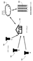
ここで図面、特に図1を参照して、本開示の一実施形態に係る有害生物監視及び/又は検出システム(広義には「有害生物監視システム」)を参照番号100で大略示している。図示実施形態において、システム100は、シロアリ(又は、他の昆虫/節足動物)等の有害生物を少なくとも監視及び/又は検出し、いくつかの実施形態においては防除するように構成されている。ただし、他の考え得る実施形態において、システム100は、他の有害生物を監視及び/又は検出し、いくつかの実施形態においては防除するように構成されていてもよく、他の有害生物としては、例えばゴキブリ、アリ等の昆虫、ラット、マウス、野ネズミ等の齧歯動物、鳥、コウモリ等が挙げられるが、これらに限定されない。
Referring now to the drawings, and in particular to FIG. 1, a pest monitoring and/or detection system (broadly referred to as a "pest monitoring system") according to an embodiment of the present disclosure is generally designated by the
システム100は、多様な用途における有害生物の監視に使用可能であり、建物(例えば、住居、事務所、貯蔵施設、倉庫等)、壁、車道、堤防/ダム、造船所、ドック、橋梁、鉄道線路、作物(例えば、サトウキビ)、果樹園、落花生(例えば、ピーナッツ)、及び/又はその他任意の適当な用途が挙げられるが、これらに限定されない。
図示のシステム100は、少なくとも一つのベイトステーション102と、ベイトステーション102から遠隔に配置され、以下により詳しく示す通り、少なくともベイトステーション102から信号を受信するとともに、いくつかの実施形態においてはベイトステーション102に信号を送信するために、ベイトステーション102と通信可能なゲートウェイ104とを具備する。表現「ベイトステーション(bait station)」は、本開示の全体に登場するが、ベイトコンポーネント(bait component)を要するものと解釈するのではなく、有害生物存否信号を発生可能な本明細書に記載の回路のハウジングとして機能するものと広く解釈すべきである。このように、ベイトステーションは、一つ以上の有害生物が侵入して有害生物存否信号を発せられる任意のハウジングと考えるべきである。同様に、「ベイトケージ(bait cage)」に対する言及でも、ベイトの構成要素を含む必要がない。むしろ、「ベイトケージ」は、本発明の電極アセンブリ及び他の構成要素を含むケージフレームとして機能する。ゲートウェイ104は、関連付けられたメモリを伴うプロセッサベース若しくはマイクロプロセッサベースの機器(コンピュータ若しくはマイクロコントローラ等)、又は縮小命令セット回路(RISC)、特定用途向け集積回路(ASIC)、及び/若しくは論理回路の任意適当な構成を適当に具備していてもよい。他の実施形態において、ゲートウェイ104は、本明細書に記載の当該ゲートウェイ104の機能を実行可能な任意の回路及び/又はプロセッサを適当に具備していてもよい。さらに別の実施形態において、ゲートウェイ104は、接続システムに組み込まれていてもよく、スマートホームシステム及び/又はホームセキュリティパネル/システムが挙げられるが、これらに限定されない。本明細書において、用語「信号」は、特定の種類の信号伝達方法に限定されず、任意適当な種類の(好ましくは)無線信号伝達(例えば、WiFi又は携帯電話)を広く表している。図1においては、ゲートウェイ104を一つしか示していないが、複数のゲートウェイ104が採用されてもよいこと及び/又はゲートウェイ104が構造物内の別の接続システムに不可欠なものでもよいことが了解される。
The illustrated
図示実施形態において、ゲートウェイ104は、ベイトステーション102のそれぞれから離隔した関係で配置されている(図1においては、8個のベイトステーションを示しているが、任意適当な数のベイトステーション102をシステム100に使用可能である)。ただし、ゲートウェイ104は、ベイトステーション102の構成要素を含むとともに、ベイトステーション102として機能するようになっていてもよいことが了解される。このため、適当な一実施形態において、ゲートウェイ104及びベイトステーション102のうちの一つは、共通アセンブリに組み込むことができる。
In the illustrated embodiment, the
考え得る一実施形態において、有害生物監視システム100は、有害生物の活動を監視及び/又は検出する現場(例えば、家の周辺)に配置された複数のベイトステーション102を具備していてもよく、ゲートウェイ104は、現場から遠隔に、当該現場に対して不動に配置されるとともに、以下により詳しく示す通り、遠隔位置からベイトステーション102と通信するようにしてもよい。考え得る別の実施形態において、ゲートウェイ104は、現場で使用するように構成されていてもよい(例えば、ゲートウェイ104は、ベイトステーション102に対して可動の、例えば技術者が現場で使用できる適当な手持ち機器(無線機器等)を具備していてもよい)。
In one possible embodiment,
図2Aを参照して、各ベイトステーション102は、大略108で示されるセンサアセンブリと、任意選択として、本明細書において詳述する通りベイト及び電極アセンブリを包囲及び/又は収容するとともに、設置位置(例えば、地中/地上)での作動に先立ってセンサアセンブリ108に結合された適当なケージフレーム101とを具備する。ステーションハウジング109は、(例えば、当該ステーションハウジングのスリット又は孔を介した)当該ステーションハウジング109に対するシロアリの出入りを可能にすることによって、以下により詳しく示す通り当該ステーションハウジング109内に配置された任意選択的なベイトマトリックス124の摂食或いは移動をシロアリが行えるように構成されている。ステーションハウジング109は、ベイトステーション102及び/又はゲートウェイ104のすべての実施形態に不要であることが了解される。図2Bを参照して、別の特徴としては、輸送、取り扱い、及び埋め込みの容易化のほか、審美性を目的として、ケージフレーム101に結合されたセンサアセンブリ108を保持するステーションハウジング109及びキャップ103が挙げられる。
Referring to FIG. 2A, each
図示のセンサアセンブリ108は一般的に、センサホルダ110、電極アセンブリ126、及び制御ユニット128を備える。以下により詳しく示す通り、図示実施形態の電極アセンブリ126はベイトマトリックス124に隣接するか、又は、ベイトマトリックス124に囲まれており、制御ユニット128は、電極アセンブリ126に電気刺激を選択的に供給するように構成されている。また、特定の実施形態において、制御ユニット128は、電極アセンブリ126に供給されている電気刺激の関数として、有害生物(シロアリ)の存否及び/又は電極アセンブリ126の少なくとも一つの電気的特性を示す信号を送信するように動作可能である。このように、制御ユニット128は、ゲートウェイ104を介して遠隔監視を容易化し、ゲートウェイ104は、制御ユニット128により送信された信号を受信可能である。
The illustrated
図17及び図18に示すように、耐水部材156が電極アセンブリ126を囲んでいてもよい。図17A及び図18Aは、一実施形態を示している。図17B及び図18Bは、代替実施形態を示している。したがって、本発明は、特定の形状にも設計要素にも限定されないものとする。耐水部材156は、発泡体で構成されているのが好ましく、任意選択として、リブ125等、有害生物の採取をさらに促進させるのに役立つ一つ以上の関心点(points of interest)を含んでいてもよい。耐水部材156は、電極アセンブリ126を囲んでおり、一方でベイトマトリックス124に囲まれている。関心点のリブ125は、図17Aに示すように、耐水部材156の長さの長手方向リブであってもよいし、図18A及び図18Bに示すように、底部又は上部等、耐水部材156の一部に集中していてもよい。さらに、図17及び図18においてより詳しく示すように、有害生物の採取に対して、面取り127及び窪み129が付加的な関心点を提供する。
A water-
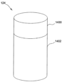
図2Aを参照して、図示のベイトマトリックス124は、第1の端面130、第2の端面132、円周外面134、及び当該ベイトマトリックス124の内部空洞137を規定する円周内面136を有する大略管状(例えば、図示実施形態では、内部通路を備えた大略円筒状)である。
Referring to FIG. 2A, the illustrated
一実施形態を円筒として示しているが、ベイトマトリックス124は、他の適当な形状であってもよいことが了解される。例えば、ベイトマトリックス124は、大略円筒状ではない管形状を有していてもよく(例えば、管形状は、実質的に多角形の断面を有していてもよく)、及び/又は、空洞は、第1の端面130から第2の端面132まで延びていなくてもよい。他の適当な実施形態において、ベイトマトリックス124は、管状ではなく、球体、角錐、立方体、又は他の適当な形状で大略成形されていてもよい。形状に関わらず、ベイトマトリックスは、当該ベイトマトリックス124の有害生物による採取を促進させる関心点を含んでいてもよい。
Although one embodiment is shown as a cylinder, it is understood that the
また、図2Aに示す管状ベイトマトリックス124の厚さ(すなわち、外面134から内面136までの横方向幅)は、図示するためのものであることが了解される。他の適当な実施形態に係るベイトマトリックス124の厚さは、図に示した厚さより相当大きくてもよいし、相当小さくてもよい。ただし、ベイトマトリックス124の厚さは、本発明の範囲から逸脱することなく、任意適当な厚さであってもよい。
It is also understood that the thickness (ie, lateral width from
適当な一実施形態において、ベイトマトリックス124は、木材、紙、厚紙等、シロアリによる摂食又は移動が可能なセルロース系材料で少なくとも一部又は全部を構成可能である。他の適当な実施形態においては、寒天マトリックス単独若しくは寒天マトリックスの糖類(すなわち、キシロース、マンノース、ガラクトース、エリスリトール、アスパルテーム、サッカリン)との組み合わせ並びに/又は純粋なセルロース材料がベイトマトリックス124として用いられるようになっていてもよい。本開示のいくつかの態様から逸脱することなく、シロアリによる摂食又は移動が可能な任意適当な材料をベイトマトリックス124として使用可能と考えられる。
In one suitable embodiment,
図示実施形態において、図19Aを参照すると、いくつかの実施形態において電極アセンブリ126がベイトマトリックス124に囲まれるように、ベイトマトリックス124の内部空洞137内に電極アセンブリ126が配置されている。例えば、電極アセンブリ126は、ベイトマトリックス124に囲まれたもの、ベイトマトリックス124に埋め込まれたもの、ベイトマトリックス124に封止されたもの、又はベイトマトリックス124に包み込まれたもののうちのいずれか一つであってもよい。他の適当な実施形態において、電極アセンブリ126は、少なくとも一部がベイトマトリックス124の内部空洞137内に配置されている。他の適当な実施形態において、電極アセンブリ126は、ベイトマトリックス124の隣り、上方、下方、近傍、周囲、又はベイトマトリックス124に対するその他任意の適当な場所に配置されている。
In the illustrated embodiment, referring to FIG. 19A, the
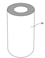
一実施形態において、センサアセンブリ108は、電極アセンブリ126を囲む耐水部材156(例えば、耐水性で、好ましくは架橋した独立気泡フォームスリーブ(closed cell foam sleeve))を具備する。本明細書において、耐水性は一般的に、防水性、耐湿性、不浸透性、及び/又は不通水性として規定される。耐水部材156は、有害生物が実際に電極アセンブリ126を貫通するまで、水又は水分を電極アセンブリ126に接触させない(ひいては、有害生物存否の誤表示を生じさせない)ように構成されている。この点において、電極アセンブリ126には、別の誤検出シグナリングを最小限に抑えるように調整された感度プロファイルが構成されていてもよい。図2A及び図2Bに示す実施形態において、耐水部材156は、大略管状であり、円周内面136により規定されたベイトマトリックス124の内部空洞137内に適合するようにサイズ規定されている。一実施形態においては、図20の断面詳細に示すように、付加的なメッシュスリーブ159が耐水部材156を囲んで、円筒圧力を生成するとともに、内部空洞137の耐水性を保証する。メッシュスリーブ159は、ポリエチレンで構成されているのが好ましく、耐水部材周りに圧力及び周応力をさらに与え、ベイトマトリックス124内の堅い適合を維持する。本発明は、これに限定されると考えるべきではないが、発明者らは、ベイトマトリックス124の耐水部材156との近接(すなわち、直接接触)によって、シロアリがベイトマトリックス124を穿孔し続け耐水部材156に入り、それにより信号を発生させる可能性が高くなると考える。シロアリの挙動に基づいて、開放空間が利用可能とならない限り又は利用可能となるまで、穿孔が継続するように見える。このため、一実施形態において、ベイトマトリックス124は、耐水部材156と直接接触するように構成されている。
In one embodiment,
他の適当な実施形態において、耐水部材156は、電極アセンブリ126を受け入れるようにサイズ規定及び成形されていてもよく、また、ベイトマトリックス124の隣り、上方、下方、近傍、周囲、又はベイトマトリックス124に対するその他任意の適当な場所に配置されていてもよい。図示実施形態において、耐水部材156は、大略第1の端面130から第2の端面132まで延びている。ただし、耐水部材156は、任意適当なサイズ又は形状が可能であることが了解される。一実施形態においては、電極アセンブリが耐水部材156内に構成されると、耐水部材156が封止される。耐水シールを保証するため、耐水部材156は、超音波シーリングで封止されるのが好ましい。耐水部材156は、大略円筒状ではない管形状を有していてもよく(例えば、管形状は、実質的に多角形の断面を有していてもよく)、及び/又は、空洞は、第1の端面130から第2の端面132まで延びていなくてもよい。他の適当な実施形態において、耐水部材156は、管状ではなく、球体、角錐、立方体、又は他の適当な形状で大略成形されていてもよい。一実施形態において、ベイトマトリックス124は、別個の耐水部材156が不要となるように、耐水材料を用いて構成されていてもよい。
In other suitable embodiments, the water-
耐水部材156は、任意適当な耐水材料から形成可能である。例えば、耐水部材156は、独立気泡押出ポリエチレン、発泡ポリスチレン、発泡ポリプロピレン等の発泡又は押出ポリマーを用いて形成されていてもよい。他の例において、耐水部材156としては、フィルム又は被膜であってもよい。例えば、適当な一実施形態において、耐水部材156としては、ベイトマトリックス124に適用された耐水性被膜であってもよい。
Water-
図2及び図3を参照して、電極アセンブリ126は、第1の電極144及び第2の電極148を含む。一実施形態において、電極144、148は、導電性材料(例えば、銅)の細長ストリップである。図示実施形態において、電極144、148は、互いに平行に延び、接触しないように離隔している。電極144、148は、ベイトステーション102に取り付けられた場合、ベイトステーション102が埋められた地面に対して実質的に垂直な方向に延びる。適当な一実施形態において、電極144、148は、大略「U」字状をなしていてもよく、電極144、148の第1の部分が地面に対して実質的に垂直に延び、電極144、148の第2の部分がベイトステーション102の底面に沿って、地面に対して実質的に水平に延び、電極144、148の第3の部分が第1の部分から離れて地面に対して実質的に垂直に延びる。他の実施形態において、電極144、148は、任意適当な材料で構成されていてもよく、また、電極アセンブリ126が本明細書に記載の通り機能し得る任意適当な形状、構成、及び/又は配向を有していてもよい。図19A(縦断面)及び図19B(斜視断面)に示すように、一実施形態において、電極144、148は、耐水部材156の壁に対して堅く適合する。一態様においては、有害生物が電極アセンブリ126と接触し得るようにするため、耐水部材156の壁にごく近接するように好適な一実施形態が電極アセンブリ126を構成する。したがって、形状に関わらず、電極アセンブリ126は、耐水部材156及びベイトマトリックス124の形状と整合するのが好ましい。したがって、この点においては、電極アセンブリ126が半剛性で、ベイトステーション102を完全に組み立てられるように、有限の場所に配置可能であるのが好ましい。
Referring to FIGS. 2 and 3,
いくつかの適当な実施形態において、電極アセンブリ126は、図2Aに示すように、電気絶縁材料(例えば、ゴム又はプラスチック材料)で構成された電極トラック157を含む。電極トラック157は、第1及び第2の電極144、148を取り付けて電極144、148の適正な配置を保証するとともに、電極144、148が互いに接触しないようにし得る基部を提供する。
In some suitable embodiments,
図2Aに示すように、第1の電極144は、電気刺激を与える信号を送信する電源回路の第1の端子160に結合されており、第2の電極148は、第2の端子162に結合されて、センサアセンブリ108の状態を監視する。電極144、148が互いに接触しないことから、第1の端子160、第1の電極144、第2の端子162、及び第2の電極148により規定される回路は、開回路である。回路が開回路である場合は、インピーダンス等の電気的特性の測定によって、無限大に近い非常に高い値が返される。このため、回路が開放されている場合は、「高インピーダンス状態」にあると称し得る。或いは、ベイトステーション102、より具体的にはベイトマトリックス124がシロアリにより採取されている場合は、電極144、148を横断して導電性材料(例えば、土、水、シロアリ排泄物、シロアリ唾液分泌物等)が配置され、回路が完全すなわち閉回路となる。回路が閉回路である場合は、インピーダンスの測定によって、測定可能な値が返される。このため、回路が閉鎖されている場合は、「低インピーダンス状態」にあると称し得る。低インピーダンス状態は、無限大に近い高インピーダンス状態の回路のインピーダンスよりも低い任意のインピーダンスを回路が有することを意味する。したがって、ベイトステーション102内のシロアリの活動によって、通常開である回路全体に測定可能なインピーダンスが生じる。
As shown in FIG. 2A, a
図示実施形態において、制御ユニット128は、少なくとも一部がセンサホルダ110の内部区画138内に配設されている。制御ユニット128は、電極アセンブリ126に既知の電気刺激を供給するように構成されている。適当な一実施形態において、電気刺激は、電流である。また、制御ユニット128は、ベイトステーション102からゲートウェイ104まで、有害生物の存否及び/又は電極アセンブリ126の一つ以上の電気的特性(例えば、抵抗又はリアクタンス)のうちの少なくとも一つを示す一つ以上の信号を有線又は無線で送信するように動作可能であってもよい。
In the illustrated embodiment,
制御ユニット128は、任意の適当なプロセッサベースの機器(例えば、実行可能命令が格納された関連するメモリを伴うマイクロコントローラ)又は縮小命令セット回路(RISC)、特定用途向け集積回路(ASIC)、及び/若しくは論理回路の任意の適当な構成を具備していてもよい。或いは、制御ユニット128は、本明細書に記載の当該制御ユニット128の機能を実行可能な任意の回路及び/又はプロセッサを適当に具備していてもよい。
また、適当な一実施形態において、制御ユニット128は、センサホルダ110の中空の内部区画138内に適当に配設されて、当該制御ユニット128への給電及び/又は適当な電気的相互接続を介した電極アセンブリ126への電気刺激の供給を行う適当な電源139及び機能回路(例えば、電気化学電池、バッテリ、電子回路等)を具備していてもよい。図21に示すように、一実施形態において、電源139は、コインセルバッテリ141であって、制御ユニット128のバッテリを堅牢に保持するとともに、組み立てられたベイトステーション102の動作の寿命を長くする。電源139は、如何なるアンテナからも離隔又は遠隔配置することによって、RF干渉を最小限に抑えるように配置されているのが好ましい。一実施形態においては、保持スナップ143の使用により、電源139を適所に取り付けて、制御ユニットを収容するセンサホルダ110の壁から離して電源139を固定するようにしてもよい。さらには、図22及び図23に示すように、好ましくは堅牢な電気的相互接続を保証すると考えられる加締め保持を使用して、接続ピン145でセンサホルダ110の底壁を形成するのが好ましい。
Also, in one suitable embodiment, the
或いは、電源139は、ベイトステーション102から遠隔に配置されていてもよく、制御ユニット128及び/又は電極アセンブリ126に対して任意の適当な様態で電気的に接続されていてもよい(例えば、ベイトステーション102の外部で複数の地上又は地下端子を利用可能とし、当該端子を介して、遠隔の電源及び/又はゲートウェイ104を制御ユニット128及び/又は電極アセンブリ126に選択的に接続してもよい)。或いは、受動的なシステムにおいては、ゲートウェイ104又は別の適当な機器により送信される信号において電源が提供されていてもよい。
Alternatively,
図2A及び図2Bに示すベイトステーション102を組み立てるため、電極アセンブリ126は、電極トラック157に結合された電極144、148を含み、電極144、148が実質的に垂直な方向に延びるように耐水部材156内に配置される。耐水部材156及びその内部に配設された電極アセンブリ126は、ベイトマトリックス124内に配置され、これがステーションハウジング109中に配置される。
To assemble the
制御ユニット128及び関連する電源139は、センサホルダ110の内部区画138内に適当に収納される。センサホルダ110は、接続機構140を用いてステーションハウジング109に結合されるように構成されている。接続機構140は、ねじ式の接続機構であってもよく、センサホルダ110がステーションハウジング109にねじ込まれる。図24に示すように、接続機構140の一実施形態には、ねじ式の接続機構を含むのが好ましく、センサホルダ110のケージフレーム101への接続によってガスケット147が圧縮されることにより、ケージフレーム101内に収容される電極アセンブリ126がさらに耐水封止される。図25においてさらに詳しく示すように、ケージフレーム101は、発泡体等の圧縮性材料151を含むチャネル149を具備していてもよい。センサホルダ110は、チャネル149に沿ったリブ付き天井部153を具備していてもよく、センサホルダ110のケージフレーム101への接続によって、天井部153が圧縮性材料151を圧縮し、これがチャネル149を満たして耐水封止を形成する。接続機構140は、ステーションハウジング109にねじ込まれるセンサホルダ110により閉鎖されるスイッチを具備する。スイッチは、閉鎖された場合、電源139を制御ユニット128に結合させて、ベイトステーションの電源オン及び動作を容易化する。したがって、センサホルダ110がステーションハウジング109にねじ込まれるまで、ベイトステーション102は電源オフ状態のままとなる。図26に示すように、一実施形態において、センサホルダ110の底部には成形されたストッパ155aがあり、ケージフレーム101の上部にある対応するストッパ155bに沿っている。センサホルダ110をケージフレーム101にねじ込むと、ストッパ155a及び155bによって、電気接点を損傷し得る過回転が防止される。さらに、ストッパ155a及び155bは、設置者に対して、接続が固定され、ステーション102が組み立てられたことの確認となる。他の実施形態においては、可視インジケータ、可聴インジケータ、又はばね荷重接点を含んでいてもよい。図24に示すように、ストッパ155a及び155bは、外周上に配置されて、成形されたプラスチック材料の物理的応力を最小化し、許容範囲をより厳格に制御する。
制御ユニット128は、電源139及び機能回路の第1の端子160及び第2の端子162それぞれを介して電極144、148に動作可能に接続され、電極144、148に電気刺激を選択的に供給できるようになっている。第1の電極144及び第2の電極148は、一切接触することなく互いに平行な方向に延びている。このように、機能回路の第1の端子160及び第2の端子162それぞれに電極144、148が結合されていることから、電極144、148間の空間によって開回路が形成される。
The
耐水部材156は、電極144、148を適当に囲んで保護する。より具体的に、耐水部材156は、電極144、148を水分から保護するように構成されている。いくつかの実施形態においては、図2A及び図2Bに示すように、ベイトマトリックス124及び耐水部材156の両者が電極144、148を囲んで保護する。
センサアセンブリ108が組み立てられたら、ステーションハウジング109の中に含めずに配置されることも可能であるし、センサアセンブリ108の少なくとも一部を含むステーションハウジングに適当に挿入されてもよい。センサアセンブリ108は、ステーションハウジングの使用なく、シロアリの活動が疑われる現場又は検出された現場において、少なくとも一部を適当に地中に埋めることができる。一方、センサアセンブリ108及び/又はそのステーションハウジングの図示実施形態は、地上配置によって、任意の適当な種類の有害生物の任意の適当な様態での配置、監視、阻止、及び/又は根絶を容易化するように適当に構成されていてもよい。例えば、センサアセンブリ108及び/又はそのステーションハウジングは、土の上、地面に対して大略水平な表面上、地面に対して傾斜した表面上、地面に対して垂直な取り付け面上(住宅若しくは建物の内部若しくは外部壁、樹木、フェンスの支柱若しくは柵、床下空間等)、又は他の適当な地上位置での適当な地上配置用に構成されていてもよい。適当な実施形態において、有害生物監視システム100は、一つ以上の地中ベイトステーション102、一つ以上の地上ベイトステーション102、並びに/又は地中及び地上ベイトステーション102の組み合わせを具備していてもよいことが了解される。
Once assembled, the
ベイトステーション102の配置後、制御ユニット128は、電極144、148に電気刺激を供給するように動作することができる。電極144、148に対する電気刺激の印加中又は印加後、制御ユニット128は、電極アセンブリ126の電気的特性(例えば、抵抗又はリアクタンス)を測定するとともに、有害生物の存否及び/又は電気的特性を示す信号をゲートウェイ104に送信するように動作することができる。
After positioning the
一実施形態において、制御ユニット128は、電気刺激の電極144、148への自動的(例えば、計画的、断続的)供給及び電気的特性の測定を行うように構成されているという意味において、自律動作するように構成されていてもよい。例えば、好適な一実施形態において、制御ユニット128は、所定の時間間隔(例えば、一日に一度、一日に二度、一週間に一度等)でステータスレポートを生成するようにプログラムされている。ステータスレポートに含まれる情報としては、インピーダンス測定低情報(impedance measured low information)、ステーションの低バッテリ状態情報、及び/又はステーションの低信号強度情報が挙げられるが、これらに限定されない。制御ユニット128は、所定の時間間隔に従って、ステータスレポートをゲートウェイ104に送信する。制御ユニット128が電気的特性を測定して、ステータスレポートを直ちに送信するため、制御ユニットによるデータの格納は不要である。別の適当な実施形態において、制御ユニット128は、測定された電気的特性が有害生物の存在を示す場合にのみ、ステータスレポート信号をゲートウェイ104に送信するように構成される。
In one embodiment, the
代替実施形態において、制御ユニット128は、遠隔制御システムによる指示を受けた場合に電極144、148に電気刺激を供給及び/又は関連する信号のゲートウェイ104への送信を行うように構成されていてもよいという意味において、適当な遠隔制御システムの指示の下に補助的な動作を行うように構成されていてもよい。このため、制御ユニット128のいくつかの実施形態では、リアルタイムで(例えば、ベイトマトリックス124の監視のたび、その直後に)信号をゲートウェイ104に送信するようにしてもよく、制御ユニット128の他の実施形態では、計画又は指示された場合に、バッチ型信号をゲートウェイ104に送信するイベントを、そのメモリに記憶してもよい。
In an alternative embodiment, the
また、いくつかの実施形態においては、シロアリの存否判定の閾値として、電気的特性の一回の読み出し又は測定が設定されていてもよい。制御ユニット128は、電気的特性の一回の測定の発生を格納又は記録して、要求された場合に(すなわち、タイミングアルゴリズム、ゲートウェイ104による外部要求等によって)当該発生を送信するようにしてもよい。例えば、適当な一実施形態において、制御ユニット128は、一日に一度の確認により、シロアリの存否を監視するようにしてもよい。或いは、電気的特性の複数の測定結果を要求するように、シロアリの存否判定の閾値が設定されていてもよい。
Further, in some embodiments, one readout or measurement of electrical characteristics may be set as a threshold value for determining the presence or absence of termites. The
センサアセンブリ108の図示実施形態が展開された場合、シロアリは、ベイトマトリックス124及びセンサアセンブリ108の位置を特定する。シロアリは、ベイトマトリックス124及び耐水部材156を貫通すると、(例えば、穿孔、採餌、採食、掘削、移動、或いは分離等によって)ベイトマトリックス124及び耐水部材156から粒子を取り出す。一部の粒子は、巣及び/又は地下穴(gallery system)に戻されて、消費/蓄積される場合もある。ベイトステーション102には、ベイトマトリックス124のみ、耐水部材156のみ、又はベイトマトリックス124及び耐水部材156の両者が設けられていてもよいことを理解されたい。
When the illustrated embodiment of
シロアリによりベイトマトリックス124及び耐水部材156から粒子が取り出されると、電極144、148は、水分侵入及び/又は電極144、148を横断して材料200を堆積させるシロアリ(図3参照)に曝される。材料200としては、例えば水、土、シロアリ排泄物、シロアリ唾液分泌物、シロアリの死骸等が挙げられる。電極144、148を横断して配置される材料200又は水分により、電極144、148及び機能回路の端子160、162によって形成された開回路が閉鎖され、測定可能な電気的特性が生じる。例えば、開回路は通常、無限大に近い抵抗を有し、低インピーダンス回路は測定可能な値を有する。電極144、148が互いに比較的ごく近接して存在することから、シロアリが耐水部材156を貫通すると、材料200が、電極トラック157上に広がり、配置され、又は蓄積されて、電極144、148間を電気的に接触させることになる。このため、シロアリの活動によって電極144、148間の回路が閉鎖され、回路が低インピーダンス状態となる。
Once particles are removed from the
電極144、148は、地面に対する垂直構成、地面に対する水平構成、地面に対する斜め構成、これらの組み合わせ、又は必要に応じた任意の適当な構成を含みこれらに限定されない、電極144、148が埋められている地面に対する任意の構成で配置されてよいことを理解されたい。さらに、電極は、互いから様々な距離で配置されてよいことが了解されるものとし、電極間の最短距離は、0、10マイクロメートル(μm)、100μm、1ミリメートル(mm)、10mmより大きな任意の距離であってよく、また、より好ましくは最大5センチメートル(cm)、最大2cm、最大10mm、最大5mm、最大1mm、最大100μm、又は最大10μmであってもよい。ただし、このような範囲は、所望の機器のサイズ及び構成に対して調整されてもよい。
The
図示実施形態においては、制御ユニット128がシロアリの存否を判定するとともに、このような存否をゲートウェイ104に送信される信号において示すのに、測定可能な電気的特性が発生しさえすれば十分である。回路は通常開回路で高インピーダンス状態にあるため、高インピーダンス状態は既知の基準となる測定可能な特性(無限大に近い高インピーダンス値)を提供する。回路は、材料200が電極144、148間を接触させた場合にのみ低インピーダンス状態となって、シロアリが耐水部材156を貫通したことを示す。したがって、測定の実際値の変化とは対照的に、測定可能な電気的特性を取得することが有害生物(シロアリ)の存否のインジケータとなるため、有害生物の存否を検出するのに、制御ユニット128が測定結果を格納/送信する必要はない。
In the illustrated embodiment, the occurrence of a measurable electrical characteristic is sufficient for
代替実施形態において、電気的インピーダンスは、電極144、148に配置された材料200の量に基づいて変化する。例えば、電極144、148に配置される材料200が増えるほど、電気抵抗が小さくなる。測定された電気抵抗のレベルは、例えばシロアリの活動の経時的な変化等、付加的な判定のため、周期的にゲートウェイ104に送信されるようになっていてもよい。
In an alternative embodiment, the electrical impedance changes based on the amount of
図示実施形態において、電極144、148に供給される電流の各パルスにより、制御ユニット128は、電気的特性を測定するとともに、測定した電気的特性に基づいて、シロアリが存在するかを判定する。例えば、適当な一実施形態において、電気的特性は、電気抵抗である。回路が開いている間は、電気抵抗の測定によって無限大に近い値が返されるが、回路が閉じると、電気抵抗は測定可能な値を返す。或いは、別の適当な実施形態において、電気的特性は、電気リアクタンスである。回路が開いている間は、電気リアクタンスの測定によってほぼゼロの値が返されるが、回路が閉じると、電気リアクタンスは異なる測定可能な値となる。シロアリの存在が判定された場合、制御ユニット128は、シロアリの存在を示す信号をゲートウェイ104に送信する。
In the illustrated embodiment, each pulse of current supplied to the
制御ユニット128は、ベイトマトリックス124の他の適当な特性を示す信号も同様に送信可能と考えられる。さらに、ベイトマトリックス124のそのようなすべての特性及びその環境を、制御ユニット128及び/又はゲートウェイ104が利用することで、それによって物件所有者に有害生物に関する状況報告が提供可能となる予測モデル又は指標モデルを作成するようにしてもよい。
It is contemplated that
また、代替実施形態において、図4及び5に示すように、制御ユニット128は、外部機器304により給電された場合に、ベイトステーション102及び/又はゲートウェイ104によって、オンにすること、起動、再設定、又は他のそのような機能を開始することが可能な一つ以上のスイッチを具備していてもよい。このようなスイッチとしては、機械的作動接点及び相互接続、磁気スイッチ、RFスイッチ、超音波スイッチ、手動スイッチ、又は追加することを選べるその他任意の上記のようなスイッチが挙げられる。有害生物監視システム100の考え得る地下位置を前提とすると、磁気リード、誘導性及び容量性、地震、赤外線、写真、熱、電界、化学、及び/又は超音波スイッチ等、受動及び/又は近接型スイッチが能動及び/又は手動型スイッチよりも好ましい場合がある。
Also, in an alternative embodiment, as shown in FIGS. 4 and 5, the
さらに別の実施形態において、有害生物監視システム100は、図5に示す通り、一つ以上のベイトステーション102及び/又は一つ以上のゲートウェイ104を起動、オン、及び/又はリセットするのに、磁気リードスイッチ302を好ましく使用できる。図5に示す通り、磁気リードスイッチ302は、電力を回路基板に供給してもよい。有害生物監視システム100を地下環境に設置できることを考え合わせると、磁気リードスイッチ302は、ロックスイッチである、超音波スイッチ等の他の選択肢よりも使用電力が少ない、確実な周囲の封止筐体を可能にするために内部に設置させ得る等、様々な利点を提供する。
In yet another embodiment, the
外部機器304による磁気リードスイッチ302の作動前に、ベイトステーション102及び/又はゲートウェイ104のうちの一つ以上は、スリープ状態又はオフ状態で省エネを図るようにしてもよい。磁気リードスイッチ302の使用により一つ以上のベイトステーション102及び/又は一つ以上のゲートウェイ104に電力が供給されると、一つ以上のベイトステーション102は、この時点で発見モード又は管理モードとなり、一つ以上のゲートウェイ104を探索することができる。別の種類のスイッチの使用により、一つ以上のベイトステーション102及び/又は一つ以上のゲートウェイ104を起動、オン、及び/又はリセットするようにしてもよいことが了解される。
Prior to actuation of
図6は、図1の有害生物監視・検出システム100の通信経路を提供する有害生物監視ネットワーク600の一例を示した図である。
FIG. 6 is a diagram illustrating an example of a pest monitoring network 600 that provides a communication path for the pest monitoring/
有害生物監視ネットワーク600には、ゲートウェイ104に通信可能に結合されたベイトステーション102を含む。有害生物監視ネットワーク600は、設置箇所ごとに一つのゲートウェイ104及び複数のベイトステーション102を有するプライベートネットワークとして構成されている。ゲートウェイ104は、クラウドサービス602中に存在する長距離無線(LoRa)ネットワークサーバへのパケット転送器として機能する。ゲートウェイ104は、住宅所有者のWiFi若しくはイーサネット接続又はセルラーSIMカードを備えたセルラーバックホールを通じてインターネットに接続されている。設置セットアップ及び通信装置のプロビジョニングを補助するため、スマートフォンアプリケーションが用いられてもよい。ネットワークサーバがパケットをミドルウェア/アプリケーションプラットフォームに送信すると、パケットが復号化され、収集データの解釈及びルーティング、解析の実行、並びにシロアリの検出及び装置保守の必要性等、プロジェクト管理専門家(PMP)への重要なイベントの通知に用いられる。
Pest monitoring network 600 includes
センサホルダ110をステーションハウジング109にねじ込んでスイッチを閉じるとともに電源139を制御ユニット128に適用することによって、ベイトステーション102が最初に起動されると、制御ユニット128は、「セットアップモード」に入る。セットアップモードの間、ベイトステーション102は、制御ユニット128を介して、ゲートウェイ104から登録の確認を受信するまで、登録リクエストをゲートウェイ104に対して周期的に送信する。登録が確認された後、ベイトステーション102は、通常動作モードに遷移し、所定の時間間隔(例えば、一日に一度)に従って、ステータス送信パケットの形態のステータス更新をゲートウェイ104に送信する。ステータス送信パケットには、ステーションID、レポート番号、センサインピーダンス測定結果、バッテリ電圧測定結果、及び/又はゲートウェイ104から最も新しく受信した確認の信号強度を含むが、これらに限定されない。
When the
ベイトステーション102からゲートウェイ104へのパケット構造は、プリアンブル>PHDR>PHDR_CRC>PHYペイロード>CRCである。
The packet structure from
ベイトステーション102とゲートウェイ104との間に選定される送信モードはLoRaであって、これは、1キロメートル超の伝送距離を利点とし、多くの障害物を通過し得る非認可の周波数スペクトルを用いた低帯域幅変調方式である。LoRaで使用する電力は小さく、ベイトステーション102からの各送信後の受信ウィンドウが短いため、ベイトステーション102は、報告間隔の間に低電力モードに移行して節電することも可能である。
The selected transmission mode between
ゲートウェイ104は、ベイトステーション102からデータを収集し、クラウド中に存在するネットワークサーバに情報を渡すように構成されている。各ベイトステーション102から受信したデータのほか、ゲートウェイ104は、各ステーションレポートのタイムスタンプ及び/又は各ベイトステーション102からの測定信号強度等、付加的なパラメータを追加するようにしてもよい。
ゲートウェイ104からクラウドへのアップリンクは、既知の任意の適当な方法を用いて接続するように構成可能なインターネット接続である。一実施形態において、インターネット接続は、インターネットにアクセスするスマートフォンで使用するのと同様に、デジタルセルラーネットワーク(例えば、3G又は4G)を用いて行われる。別の実施形態においては、データをインターネットクラウドデータベースに渡すため、顧客WiFiネットワークに対するWiFi接続が確立されてもよい。また、別の実施形態において、ゲートウェイ104は、有線イーサネット接続を通じて、住宅所有者のルータに直接接続することも可能である。
The uplink from
ネットワークサーバは、クラウドサービス602中に存在し、どのベイトステーション102がどのゲートウェイ104及び顧客宅内の場所と関連付けられているかの記録をつけるのに用いられる。また、(a)機器をネットワークに参加させるための機器作動、(b)機器デューティサイクルネゴシエーション(例えば、各フレーム間のX秒の待機)又はバンド幅ネゴシエーション等、使用する領域/帯域に応じた無線調節、(c)無線チャネル選択、(d)機器クラス支持(A、C、B)、(e)フレーム重複排除(複数のゲートウェイが機器フレームを受信した場合)、(f)フレームダウンリンクルーティング(最適なダウンリンク経路を選択)、(g)フレーム完全性(データが破損していないことを保証)、(h)フレーム暗号化/復号化(データ傍受の回避)、(i)フレームカウンタチェック(リプレイアタックの禁止)、(j)LoRaWANバージョン全体の後方互換性、(k)終点からアプリケーションサーバへのデータパケットのリアルタイムのルーティング、(l)エンドノード、ネットワークサーバ、及びアプリケーションサーバ間のセキュリティキーの認証、並びに(m)ネットワークスループット、ネットワーク可用性、パケット損失、パケット遅延、及び/若しくはパケット遅延ジッタ等のネットワーク効率測定基準の管理といったプロセスを担う。
A network server resides in the
ネットワークサーバは、IPアドレスを通じてデータをアプリケーションサーバに送信するが、その後は、監視エンティティがこれにアクセスして、(a)パケットの復号化、(b)解析、(c)PMP関連タスク、(d)SAP関連タスク、(e)フルフィルメント(Fulfillment)、及び/又は(f)マーケティングコミュニケーションを実行する。 The network server sends the data to the application server through the IP address, which can then be accessed by the monitoring entity to (a) decrypt the packet, (b) parse it, (c) perform PMP-related tasks, and (d ) Perform SAP-related tasks, (e) Fulfillment, and/or (f) Marketing communications.
ゲートウェイは、プリアンブル>PHDR>PHDR_CRC>PHYペイロード>CRCというフォーマットで、アップリンクメッセージをネットワークに送信することになる。 The gateway will send the uplink message to the network in the format Preamble>PHDR>PHDR_CRC>PHY Payload>CRC.
また、ネットワークサーバは、ゲートウェイへの必要なダウンリンクメッセージの送信も担う。パケット構造は、プリアンブル>PHDR>PHDR_CRC>PHYペイロードである。 The network server is also responsible for sending the necessary downlink messages to the gateway. The packet structure is Preamble>PHDR>PHDR_CRC>PHY payload.
高いレベルにおいて、ミドルウェア/アプリケーションプラットフォームは、パブリック又はプライベートクラウド上に存在するオンデマンドのスケーラブル且つセキュアなコンピューティングシステムを構成する一群のマイクロクラウドサービスである。このプラットフォームは、IoTプロジェクトに関するゲートウェイ104及びベイトステーション102の発見、識別、目録化、接続、及び制御が可能である。
At a high level, a middleware/application platform is a collection of microcloud services that constitute an on-demand, scalable, and secure computing system that resides on a public or private cloud. This platform is capable of discovering, identifying, cataloging, connecting, and controlling
機器は、MQTT、WiFi、IP、セルラー、又は衛星を通じてプラットフォームにつながる。この接続は、直接的であってもよいし、ゲートウェイ/ネットワーク又はモバイル機器を介して統合されていてもよい。機器がプラットフォームに接続されると、データが(該当する場合)正規化され、REST APIを介して、(a)APIを介しての履歴データのマイニングのためにサービスプロバイダがデータを利用可能となった場合のデータ格納/管理、(b)特定の日時及び時間帯に基づく時限イベント(timed events)のスケジューリング、(c)特定の閾値の超過又は満足に基づくSMS/電子メール警報、(d)シロアリの検出、低バッテリ、及び/又はゲートウェイ104とベイトステーション102のうちのいずれかとの間の低信号強度等、サービスプロバイダへの通知を促進するIf/Thenイベントトリガ、(e)データ視覚化、並びに(f)LoRa追跡といった機能が利用可能となる。REST APIによれば、外部のビジネスインテリジェンス、人工知能、及び他の第三者サービスがミドルウェア/アプリケーションレイヤを消費する又はミドルウェア/アプリケーションレイヤと相互作用することが可能となる。
Devices connect to the platform via MQTT, WiFi, IP, cellular, or satellite. This connection may be direct or integrated via a gateway/network or mobile device. Once the equipment is connected to the platform, the data is normalized (if applicable) and made available via the REST API to service providers for (a) mining historical data via the API; (b) scheduling of timed events based on specific dates and times; (c) SMS/email alerts based on exceeding or satisfying specific thresholds; (d) termite detection of low battery, and/or low signal strength between the
システム100の設置は、設置者は、顧客宅内でゲートウェイ104を設置することから始める。通常は、商用電源へのアクセス及びインターネットアクセスの計画的な方法へのアクセスのある屋内に設置される。ゲートウェイ104は、電力の供給及びWiFi、イーサネット、又はセルラーを通じた接続の後、LEDステータス照明により示される確認モードに入る。ゲートウェイ104の接続ステータスが完了(すなわち、緑色のソリッド(solid)LED照明)すると、設置者は、スマートフォンアプリケーションを用いてバーコードラベルからゲートウェイIDを読み出し、(a)ネットワークサーバに対するゲートウェイアップリンク(ダウンリンク確認を伴う)、(b)ネットワークサーバパケット認証、(c)ネットワークサーバ及びアプリケーションサーバ認証、(d)ネットワークサーバからゲートウェイへのダウンリンク、(e)スマートフォンアプリケーション認証への適用といった認証ステップを介してゲートウェイ104が登録される。
Installation of
セルラーネットワークがアップリンクとして用いられる場合は、ゲートウェイ104のSIMカードデータの入力によって、ゲートウェイ通信が可能となる。顧客WiFiネットワークが用いられる場合は、設置者のスマートフォンとゲートウェイとの間にローカルWiFi接続を確立して、顧客のネットワークSSID及びパスワードを入力することが必要となり得る。
If a cellular network is used as an uplink, entry of SIM card data for
設置者は、ガイドラインに従ってベイトステーション102の配置を選定し、各ベイトステーション102をATBS筐体中に設置する。設置者は、設置用スマートフォンアプリケーションを使用して、各ベイトステーション102のバーコードIDを読み込むことにより、各ステーションを登録する。
The installer selects the placement of the
上述の通り、設置者が電子モジュールをベイトアセンブリにねじ込むと、ベイトステーション102は、起動してセットアップモードに入り、登録リクエストを周期的(例えば、30秒ごと)にブロードキャストする。その後、ゲートウェイ104は、リクエストを受信し、それをネットワークアプリケーションサーバに送信して認証を受ける。アプリケーションサーバは、スマートフォンアプリケーションとの通信によって、当該ベイトステーション102の設置が完了したことを確認する。そして、スマートフォンアプリケーションは、次のステーションに移るよう設置者に知らせる。
As mentioned above, when the installer screws the electronic module into the bait assembly, the
設置者は、最後のベイトステーション102を設置した後、スマートフォンアプリケーション上で設置を完了するオプションを選択する。システムは、オンして、ネットワーク及びアプリケーションサーバと通信するゲートウェイ104にすべてのリアルタイムのステーションデータを送信し、確認することによって、テスト確認を実行する。スマートフォンアプリケーションは、設置が完了したことを確認して、設置者に設置場所を通知する。その後、システムは、通常動作モードに入り、前述の通り、所定の時間周期でデータを送信する。
After installing the
ゲートウェイ104は、(a)内部及び/又は(b)外部通信が可能である。ゲートウェイ104の内部通信は、ネットワークを用いて行われるようになっていてもよい。ゲートウェイ104の外部通信は、図7~図12に示すように、ホームセキュリティ(HS)ハブ402、さらには通信ポータル404に送られるようになっていてもよい。ゲートウェイ104及びHSハブ402は、WiFi接続、インターネット接続、イーサネット接続、セルラー接続、及び/又はその他任意の適当な形態の通信手段を用いて、ゲートウェイ104及び/又はHSハブ402及び/又は通信ポータル404から外部にデータを送信できることが了解される。HSハブ402及び/又は通信ポータル404は、有害生物監視システム100を使用する顧客並びに/又はその他任意の外部源により提供されるようになっていてもよい。HSハブ402及び/又は通信ポータル404は、センサ/ネットワークデータの外部ホストクラウドへの定期的な記録を可能にする。ゲートウェイ104からクラウドへのデータの伝送には、アプリケーションプログラミングインターフェース(API)が用いられるようになっていてもよい。また、ベイトステーション102からゲートウェイ104へのデータの伝送には、APIが用いられるようになっていてもよい。また、クラウドからウェブインターフェースへのデータ伝送にAPIが用いられるようになっていてもよい。APIは、JSON、XML、又はMessagePack、protobuf、bson、avro、若しくはその他任意のバイナリフォーマット等、他のテキストベースのフォーマット若しくはバイナリシリアライゼーション等、様々な異なるフォーマットで記述されていてもよい。
いくつかの適当な実施形態において、ゲートウェイ104は、(図7~図12に示すように)スマートホームシステム及び/又はホームセキュリティパネル/システムを含み、それらに限定されない、接続システム又はネットワークに組み込まれ得ることが了解される。このような実施形態においては、HSハブ402及び/又は通信ポータル404がゲートウェイ104として機能し、ベイトステーション102がHSハブ402及び/又は通信ポータル404と直接通信し得る。このような通信においては、WiFi接続を使用するのが好ましいが、インターネット接続、イーサネット接続、セルラー接続、及び/又はその他の任意の適当な形態の通信手段がデータ送信に使用され得る。また、ベイトステーション102の少なくとも一部が地下に存在する場合は、ベイトステーション102とHSハブ402及び/又は通信ポータル404との間の通信に、低電力ワイドエリアネットワーク(LPWAN又はLoRaWAN)接続が用いられてもよい。
In some suitable embodiments, the
例示的な実施形態において、ゲートウェイ104は、複数のベイトステーション102並びにHSハブ402及び/若しくは通信ポータル404と通信可能に結合されている。ゲートウェイ104は、複数のベイトステーション102とHSハブ402及び/又は通信ポータル404との間のゲートウェイとして作用する。例示的な実施形態において、ゲートウェイ104は、ベイトステーション102とHSハブ402及び/又は通信ポータル404との間のセキュアな通信リンクを提供する一方、通信のフィルタリングによって、サイバーセキュリティの脅威を防止する。例示的な実施形態において、ゲートウェイ104は、ベイトステーション102のそれぞれとセキュアな通信チャネルを確立する。セキュアな通信チャネルは、二方向通信チャネルである。いくつかの実施形態において、セキュアな通信チャネルは、暗号データを送受信する。いくつかの別の実施形態において、セキュアな通信チャネルは、認証情報を通信に含めることを要求する。セキュアな通信チャネルは、他の方法での保護によって、本明細書に記載のシステム及び方法が機能し得るようにしてもよい。
In the exemplary embodiment,
ゲートウェイ104は、動作に際して、(a)当該ゲートウェイ104によるベイトステーション102の検出及びネットワークへの追加を可能にする管理モード(保守モード又は発見モードとも称し得る)又は(b)レポートモードという二つの異なるモードを有していてもよい。ゲートウェイ104は、管理モードに設定されている場合、そのネットワークに追加するベイトステーション102を探索しており、発見したベイトステーション102に試験用パケットを送り出す。ゲートウェイ104は、その最初の作動時に、デフォルトが自動で管理モードとなるようにするのが望ましい場合もある。ベイトステーション102は、ゲートウェイ104のネットワークに取り付けられたら、別段の指定及び/又はリセットがない限り、他の如何なるネットワークにもつながろうとしない。ゲートウェイ104及びベイトステーション102の両者は、形成されるネットワークに関して、管理モードへの設定が必要となり得ることを理解されたい。また、モバイル機器アプリケーションの使用によって、ゲートウェイ104を管理モードに設定するようにしてもよい。有害生物監視システム100の設定に際しては、設置者がまず、ゲートウェイ104をオンし、管理モードにした後、個々のベイトステーション102の作動によって有害生物監視システムのネットワークを形成するようにしてもよい。有害生物監視システム100は、本明細書に記載の通り、スター型ネットワークを用いて通信を行うのが好ましく、スター型ネットワークでは各ベイトステーション102がゲートウェイ104と直接通信する。
The
また、ゲートウェイ104は、(a)ベイトステーション102と情報を送信若しくは受信する有害生物監視システムネットワーク上の内部通信、又は(b)遠隔機器及び/若しくはクラウドと情報を送信若しくは受信する外部通信という二つの異なる通信モードを有していてもよい。ベイトステーション102からデータを受信するため、有害生物の活動の存否の判定に応じたゲートウェイ104への信号の自動送信を各ベイトステーション102が行うように構成されていてもよく、及び/又はゲートウェイ104が所定間隔でネットワーク上の個々のベイトステーション102を確認してもよい。
The
ゲートウェイ104は、そのネットワークに属するベイトステーション102を把握していてもよい。一方、ベイトステーション102自体は、具体的に対話している相手を認識していない。ゲートウェイ104は、少なくともベイトステーション102から送られたデータを外部箇所及び/又は機器に送るまで、当該データを格納するように構成されている。ゲートウェイ104は、命令の受信並びに/又はベイトステーション102及び/若しくはゲートウェイ104のファームウェアにプログラムされた時間間隔の経過に際して、データをクラウド又は外部源に送信するのが好ましい。ゲートウェイ104は、以下により詳しく説明する通り、プログラムされた時間間隔において及び/又は遠隔機器で用いられるモバイルアプリケーションからのリクエストに応じて、データをクラウド及び/又は外部源に送信するようにしてもよいことが了解される。
ゲートウェイ104は、ベイトステーション102及び/又はゲートウェイ104の両者として機能するようになっていてもよく、また、他のベイトステーション102及び/又はゲートウェイ104の両者との内部通信のほか、外部通信が可能であってもよいことが了解される。
The
図5に示すように、ゲートウェイ104は、磁気リードスイッチ302及び/又は超音波スイッチ301を有していてもよい。超音波センサがゲートウェイ104上の超音波スイッチ301に給電するとともに、ゲートウェイ104の停止/起動サイクルに用いられるようになっていてもよい。超音波スイッチ301によって、遠隔機器を用いたゲートウェイ104の遠隔起動が可能となり得る。これにより、ゲートウェイ104がその計画的ダウンロード毎にデータを送り出すのを待つのではなく、ゲートウェイ104に格納されたデータをそのタイミングで瞬時にダウンロードできるようになる。ゲートウェイ104に格納されたデータは、ベイトステーション102からゲートウェイ104への最新のレポートデータであってもよいことが了解される。
As shown in FIG. 5, the
電話又は手持ち機器等のモバイルクライアントは、(a)ゲートウェイ104に接続されたすべてのベイトステーション102の一覧を取得し、(b)ベイトステーション及び/若しくはゲートウェイ104をリセットし、(c)ゲートウェイ104を顧客のホームネットワーク(WiFiネットワーク若しくは携帯電話ネットワーク等)にリンクさせ、(d)ホストクラウドレポートを設定し、(e)顧客のホームネットワークをチェックし、(f)ネットワークからベイトステーション102を消去し、(g)ベイトステーション102及び/若しくはゲートウェイ104を発見モードにし、並びに/又は(h)ネットワーク全体を消去する、という動作を実行可能であることが了解される。
A mobile client, such as a phone or handheld device, can (a) obtain a list of all
いくつかの実施形態において、超音波スイッチ301は、地下環境においてより良く作用し得るため、例えば赤外線スイッチ等の他種のスイッチよりも好ましい場合があることが了解される。超音波スイッチ301は、超音波送信機及び超音波受信機の組み合わせに依拠する。送信機が超音波信号を発すると、これが無線で超音波受信機に送信された後、超音波受信機により、様々な機能に使用可能な電気信号に変換される。本開示の主題である有害生物監視システム100において、超音波スイッチ301又は機器は、有害生物監視システム100の一部であるセンサホルダ110内に存在する。有害生物監視システム100中のゲートウェイ104及び/又はベイトステーション102は、地中、地表、又は地上に設置されたプラスチックセンサハウジング(図示せず)内に設置されていてもよい。また、有害生物監視システム100の構成要素は、プラスチックセンサハウジングを使用することなく、同様に地中、地表、又は地上に設置されていてもよい。超音波送信機が発した信号は、センサの覆いのほか、任意のセンサハウジング材料を通過する必要がある。また、超音波信号は、土壌、マルチ、又は壁、コンクリート、及び/若しくは人工障壁等の他の材料(すなわち、有機又は無機)の通過が必要となる場合もある。地下環境のほか、機器の周囲のプラスチック材料を通って伝わる能力が高いため、赤外線よりも超音波信号を使用するのが好ましい。超音波スイッチ301の使用は、現場でテストが行われ、有害生物監視システム100内で所要の動作機能を作動できる点において有効であることが証明されている。超音波送信機は、超音波信号を発し得る如何なる種類の手持ち機器であってもよいことが了解される。
It will be appreciated that in some embodiments,
図7~図12に例示する一実施形態において、有害生物監視システム100は、接続システム又はHSハブ402に直接組み込まれていてもよい。本願の目的のために、接続システムは、工業、住居及び/又は商業施設内の任意の自動又は無線相互接続及び/又は接続システムを意味することが了解される。接続システムは、HSハブ402等、すべての機器の通信を集める通信中央点又は機器を有していてもよい。また、接続システムによれば、工業、住居又は商業施設内の様々な機器は、相互の通信又は中央位置との通信が可能であることが了解される。このような機器としては、火災/煙探知機、侵入検出器、医療警報機器、エネルギー管理機器、水/漏洩検出機器、灌漑システム、スマート家電、照明機構、ドアロック、窓センサ、ビデオ/オーディオ機器等が挙げられるが、これらに限定されない。また、接続システムは、HSハブ402及び/又は通信ポータル404を通じて、施設400から分散ネットワークシステム若しくは通信ポータル404、又はクラウド、単一サーバシステム、若しくは類似システム等の別の外部源へと外部通信するようにしてもよいことが了解される。有害生物監視システム100は、住居及び/若しくは商用の接続システム並びに/又は分散ネットワークシステムと互換であってもよい。有害生物監視システム100は、直接設置されるとともに、サービスプロバイダによって、既存及び/又は個人による接続システムの一部に組み込まれていてもよく、ホームセキュリティプロバイダ、建設業者、有害生物管理専門家、他の技術サービスプロバイダ及び/又は施設所有者等が挙げられるが、これらに限定されない。
In one embodiment illustrated in FIGS. 7-12,
前述の通り、有害生物監視システム100は、消費及び/又は移動可能なベイトマトリックス124内、ベイトマトリックス124上、又はベイトマトリックス124周囲の有害生物の活動を検出するように設計されている。有害生物の活動の検出に有効と決定された距離で間隔を空けた状態で工業施設、商業施設、及び/又は住居構造物400のほか、堤防、ドック、鉄道線路、及びこのような他の木材ベースの構造物に近接して、一つ以上のベイトステーション102及び少なくとも一つのゲートウェイ104が設置されていてもよい。様々なベイトステーション102及び/又はゲートウェイ104間のこのような間隔は、5~30フィート、5~15フィート、及び1~100フィートであってもよい。
As previously discussed, the
有害生物によるベイトマトリックス124の一部の取り去りによって、個々のベイトステーション102からゲートウェイ104又は、これらに限定されないが、データ管理、格納、解析、並びに/又は技術プロバイダ、設置会社、及び施設所有者を非限定的に含む認定者への伝達のための分散ネットワークシステムに伝えられる信号が発せされるようになっていてもよい。図7~図12に示すように、信号は、ゲートウェイ104から接続システムのHSハブ402を通って通信ポータル404及びその先へ送信されるようになっていてもよい。有害生物の活動を示す信号は、接続システムのサービスプロバイダ(406、412)によって、適当な受信者(410、413、414、416、418等)へとさらにルーティングされるようになっていてもよく、技術所有者、認定サービスプロバイダ、及び/又は施設/物件所有者400が挙げられるが、これらに限定されない。認定サービスプロバイダ(414、416)に、潜在的な有害生物の脅威が通知され、それに対する応答が要求される場合がある。
Dislodgement of portions of
これらに限定されないが、セキュリティ及び監視業界で一般的な既存の技術、インフラ、及び専門知識を利用することにより、監視プロセスの複雑さが抑えられ、脅威が伝達されるとともに、脅威への応答が容易化される。有害生物監視システム100の接続システム(これに限定されない)への組み込みによって、元はセキュリティ及び監視業界が提供していたのと同じようなレベルの施設保護及び安心がもたらされる可能性があり、それらには、有害生物の活動に関する従来の視覚的検査を必要としない生命の安全(火災、侵入、医療)及び/又はライフスタイル(温度、照明、ドア等)管理が挙げられるが、これらに限定されない。有害生物監視を別のホームセキュリティ/監視システムと組み合わせることによって、より広範な快適さ及び安心が物件所有者にもたらされる。有害生物監視システム100によって有害生物が検出された場合は、警報がセキュリティ会社に直接伝わり、有害生物監視プロバイダ、監視している施設の窓口、管理者、若しくは所有者、並びに/又は有害生物監視システム100を提供している会社のうちの一つ以上に警報が送信されるようになっていてもよいことが了解される。
By leveraging existing technology, infrastructure, and expertise common in the security and surveillance industry, including but not limited to, the complexity of the surveillance process is reduced and threats are communicated and responded to. Facilitated. The incorporation of
いくつかの実施形態においては、シロアリの存在を示すベイトステーション102からの信号の受信に際して、建物/構造物の所有者/連絡先に通知するための警報をHSハブ402が生成する。この警報には、HSハブ402に接続されたスマートテレビの有害生物警報の表示、建物/構造物内の照明の所定順序での点滅、及び/又は建物/構造物のドアベルを所定順序で鳴らすことを含んでいてもよいが、これらに限定されない。
In some embodiments, upon receiving a signal from
ゲートウェイ104により集められたデータの通信は、多様な手段により行われるようになっていてもよく、(a)ベイトステーション102(又はゲートウェイ104)からデータを受信するHSハブ402、(b)データ源(HSハブ402の有無に依らない)からクラウドへのデータ送信を可能にするとともに、WiFiルータ、携帯電話等の機器を備え得る通信ポータル404、(c)通信ポータルから送信済みの可能性があるクラウドデータをホスティング可能なHS会社データサービス406、(d)ホームセキュリティ会社等のサービスプロバイダ410、(e)DM会社又はデータ管理会社412/413、(f)検出された任意の有害生物に対処し得る有害生物管理専門家「PMP」(ルーティングサービス414/416の有無に依らない)、(g)PMPに通知するPMルーティングサービス418、(h)住居又は物件所有者400、及び/又は(i)クラウドサービスネットワークプロバイダ407のうちの一つ以上との通信を含んでいてもよいことが了解される。図7~図12は、様々な通信経路の例を与えている。これらの経路は調整可能であり、有害生物監視システム100の共通の目標は、有害生物の存在に関するデータをシステム100の場所から最終的に物件所有者及び/又は有害生物管理専門家等のサービスプロバイダへと提供することであることが了解される。この目的を実現するために、様々な中間通信経路を使用可能であることが了解される。
Communication of data collected by
本開示の別の実施形態は、従前又は従来のベイトを現場に配置した後、ベイトを消費しているシロアリ(又は、他の昆虫/節足動物)が現場の施設に進入しているシロアリ(又は、他の昆虫/節足動物)と同じであるかを判定する方法である。したがって、このような判定を容易化するベイトを提供することが有用となる。 Another embodiment of the present disclosure provides that after placing a conventional or conventional bait on a site, termites (or other insects/arthropods) that are consuming the bait are invading the site facility. or other insects/arthropods). Therefore, it would be useful to provide bait that facilitates such determination.
一実施形態において、ベイトは一般的に、多糖類担体材料と、担体材料と混ぜ合わされたマーカ材料とを含む。マーカ材料は、昆虫(又は、別の節足動物)が消費可能であり、昆虫(又は、別の節足動物)の観察に際して、昆虫(又は、別の節足動物)がベイトを活発に食べている旨の判定を容易化する物質を含む。 In one embodiment, the bait generally includes a polysaccharide carrier material and a marker material mixed with the carrier material. The marker material is consumable by the insect (or another arthropod), and upon observation of the insect (or another arthropod), the insect (or another arthropod) is actively eating the bait. Contains substances that facilitate the determination that
別の実施形態において、昆虫を監視する方法は一般的に、現場の第1の場所にベイトを配置するステップを含み、ベイトは、昆虫/節足動物がベイトを活発に食べている旨の判定を容易化するマーカ材料を含む。また、この方法は、ベイトでの昆虫/節足動物の活動を監視するステップと、監視の結果としてベイトでの昆虫/節足動物の活動のレベルを検出するステップと、検出の結果としての昆虫/節足動物の活動に関して、現場の第2の場所を視覚的に検査するステップとを含む。この方法は、第2の場所の昆虫/節足動物を観察することにより、昆虫/節足動物がマーカ材料を消費し、ベイトを活発に食べているものと判定するステップをさらに含む。 In another embodiment, a method of monitoring insects generally includes placing a bait at a first location at a site, wherein the bait is determined by determining that the insect/arthropod is actively feeding on the bait. Contains marker material to facilitate. The method also includes the steps of monitoring insect/arthropod activity on the bait, detecting the level of insect/arthropod activity on the bait as a result of the monitoring, and detecting the insect/arthropod activity on the bait as a result of the monitoring. /visually inspecting the second location of the scene for arthropod activity. The method further includes determining that the insect/arthropod has consumed the marker material and is actively feeding on the bait by observing the insect/arthropod at the second location.
図13は、導電性ベイトマトリックス1400及び非導電性ベイトマトリックス1402を含む、(図1に示す)有害生物監視システム100と併用し得る例示的なベイトマトリックス124の斜視図である。好適な一実施形態において、「導電性ベイトマトリックス」は一般的に、導電性粒子を含むベイトマトリックスを意味することが了解される。また、ベイトが導電性粒子を含むものの、それ自体は導電性ではない場合もあることを理解されたい。本開示の目的のため、この種のベイトは、「導電性ベイト」とも称する場合がある。一実施形態において、ベイトマトリックス124は、導電性ベイトマトリックス1400のみを含む。
FIG. 13 is a perspective view of an
ただし、他の実施形態において、ベイトマトリックス124は、一つ以上の部分を含み、少なくとも一つの部分が導電性ベイトマトリックス1400を含み、第2の部分が非導電性ベイトマトリックス1402を含み得るのが好ましい場合もある。
However, in other embodiments,
さらに、他の適当な実施形態においては、ベイトマトリックス124が非導電性となり得る(すなわち、導電性粒子を実質的に含まないベイトマトリックス1402のみを含む)ことが了解される。
Furthermore, it is appreciated that in other suitable embodiments,
導電性ベイトマトリックス1400は、ベイトマトリックス124全体(導電性の部分1400及び非導電性の部分1402)のサイズの最大5%、ベイトマトリックス124全体の最大10%、ベイトマトリックス124全体の最大15%、ベイトマトリックス124全体の最大30%、ベイトマトリックス124全体の最大50%、ベイトマトリックス124全体の最大75%、及び/又はベイトマトリックス124全体の最大100%であってもよい。
The
適当な一実施形態において、以下の表2に示すとともに本明細書の実施例1でより詳しく示す通り、導電性ベイトマトリックス1400は、有害生物に強く受け入れられ、有害生物による消費又は移動に好ましい場合もある。
In one suitable embodiment, as shown in Table 2 below and in more detail in Example 1 herein, the
さらに、図1に示すベイトマトリックス124は、導電性ベイトマトリックス1400を含むことなく、有害生物に強く受け入れられるとともに、有害生物による消費又は移動に好ましい場合もあることが了解される。
Furthermore, it is understood that the
一実施形態に係るベイトマトリックス124は、大略固体の構成である。代わりに、他の実施形態において、ベイトマトリックス124は、半固体(例えば、ジェルの形態)であってもよいし、大略液体の状態(例えば、流体懸濁液の形態)であってもよい。特に適当な一実施形態において、ベイトマトリックス124は、押し出しベイトマトリックスである。
適当な一実施形態に係るベイトマトリックス124及び/又は導電性ベイトマトリックス1400は、担体材料及び複数の導電性粒子及び/又は複数の受け入れ可能性増大粒子を含む。非導電性ベイトマトリックス1402は、導電化及び/又は電荷輸送のための導電性粒子を含んでいなくてもよいし、十分に含んでいなくてもよいことが了解される。また、導電性ベイトマトリックス1400は、ベイトマトリックス124の一部(導電性の部分1400)に過ぎなくてもよいことが了解される。さらに、導電性ベイトマトリックス1400に対しては、電荷が適用されてもよし、適用されなくてもよいことが了解される。一実施形態に係る導電性粒子又は摂食刺激性粒子は、鉄、亜鉛、マグネシウム、銅、又はアルミニウム等の金属粒子であってもよいが、これらに限定されない。粒子は、塵状、酸化物状、粉状、スラグ状、フレーク状、又は他の適当な粒子形態等、任意の適当な粒子形態であってもよい。
According to one suitable embodiment, the
他の実施形態において、導電性粒子又は摂食刺激性粒子は、半金属又は非金属の導電性粒子である。一実施形態に係る適当な例としては、黒鉛、カーボンナノチューブ片、カーボンブラック、コークス、及び炭化炭粉等のカーボンベースの粒子が挙げられるが、これらに限定されない。 In other embodiments, the conductive particles or phagostimulant particles are semimetallic or nonmetallic conductive particles. Suitable examples, according to one embodiment, include, but are not limited to, carbon-based particles such as graphite, carbon nanotube pieces, carbon black, coke, and carbonized carbon powder.
特に適当な一実施形態において、導電性粒子又は摂食刺激性粒子は、黒鉛の粒子である。黒鉛は、例えば片状黒鉛、非晶質黒鉛、鱗状黒鉛、膨張性黒鉛、又は高配向性熱分解黒鉛(HOPG)等の様々な種類で利用可能である。 In one particularly suitable embodiment, the electrically conductive particles or phagostimulant particles are particles of graphite. Graphite is available in various types, such as flake graphite, amorphous graphite, scale graphite, expandable graphite, or highly oriented pyrolytic graphite (HOPG).
黒鉛は、EDM等級(例えば、「Properties and Characteristics of Graphite, For the EDM Industry」、Fifth Printing-February 2002,1987、Poco Graphite, Inc.、POCO Graphite, Inc.、300 Old Greenwood Rd. Decatur, TX 76234に記載)、工業等級(例えば、「Industrial Material Solutions」、Poco Graphite Inc.、brochures IND-92480-0514, 6204-7085INK-0414, all 2014に記載)、半導体等級、イオン注入等級、生物医学等級(例えば、「Biomedical Grade Graphites」、Poco Graphite Inc.、Brochure IND-7334-0514に記載)、及びグラスメート(Glassmate)等級(例えば、「Glassmate」、Poco Graphite Inc.、brochure GLA 102930-0214, 2014に記載)等、様々な用途向けに様々な等級のものが市販されている。 Graphite is EDM grade (e.g., "Properties and Characteristics of Graphite, For the EDM Industry," Fifth Printing-February 2002,1987, Poco Graphite, Inc., 300 Old Greenwood Rd. Decatur, TX 76234 ), industrial grade (e.g., listed in "Industrial Material Solutions", Poco Graphite Inc., brochures IND-92480-0514, 6204-7085INK-0414, all 2014), semiconductor grade, ion implantation grade, biomedical grade ( For example, "Biomedical Grade Graphites", Poco Graphite Inc., Brochure IND-7334-0514) and Glassmate grades (e.g., "Glassmate", Poco Graphite Inc., Brochure GLA 102930-0214, 2014) A variety of grades are commercially available for various uses, such as (as described).
異なる種類及び等級の黒鉛は、例えば密度、ショア硬さ、ロックウェル硬さ、曲げ強度、熱膨張、熱伝導性、熱容量、放射率、圧縮強度、電気抵抗率、又は平均粒子サイズ等の特性のうちの一つ以上が異なることがよく知られている。 Different types and grades of graphite have different properties such as density, Shore hardness, Rockwell hardness, flexural strength, thermal expansion, thermal conductivity, heat capacity, emissivity, compressive strength, electrical resistivity, or average particle size. It is well known that one or more of these are different.
一般的には、ベイトマトリックスへの組み込みによってベイトマトリックスの食味選好が促進されることを前提として、如何なる種類且つ如何なる等級の黒鉛が用いられてもよい。適当な一実施形態において、導電性粒子を含む材料は、導電性ポリマーを製造するための導電性フィラーとして、黒鉛製造業者(例えばアズベリーグラファイトミルズ社(Asbury Graphite Mills, Inc.))が提供する黒鉛である。一実施形態において、導電性粒子を含む材料は、超微細黒鉛及び/又は超大表面積黒鉛である。 In general, any type and grade of graphite may be used, provided that its incorporation into the bait matrix promotes the taste preference of the bait matrix. In one suitable embodiment, the material comprising conductive particles is graphite provided by graphite manufacturers (e.g., Asbury Graphite Mills, Inc.) as a conductive filler for producing conductive polymers. It is. In one embodiment, the material containing the conductive particles is ultrafine graphite and/or ultrahigh surface area graphite.
適当な一実施形態において、黒鉛の平均粒子サイズは、1μm~20μm、1μm~15μm、1μm~10μm、1μm~5μm、1μm~3μmであってもよい。平均粒子サイズを決定する方法は、当業者によく知られている。一実施形態において、黒鉛の表面積は、1m2/g~500m2/g、20m2/g~400m2/g、50m2/g~300m2/gの範囲である。 In one suitable embodiment, the average particle size of the graphite may be between 1 μm and 20 μm, between 1 μm and 15 μm, between 1 μm and 10 μm, between 1 μm and 5 μm, and between 1 μm and 3 μm. Methods for determining average particle size are well known to those skilled in the art. In one embodiment, the surface area of the graphite ranges from 1 m 2 /g to 500 m 2 /g, 20 m 2 /g to 400 m 2 /g, 50 m 2 /g to 300 m 2 /g.
電気抵抗率(抵抗率、電気比抵抗、又は体積抵抗率としても知られている)は、所与の材料が電流の流れに対抗する強さを定量化する固有特性である。当業者は、電気抵抗率を測定する方法を熟知している。例えば、黒鉛サンプルの電気抵抗率を測定する標準的な一方法は、ASTM C611-98に記載されている。 Electrical resistivity (also known as resistivity, electrical resistivity, or volume resistivity) is an inherent property that quantifies the strength with which a given material resists the flow of electrical current. Those skilled in the art are familiar with how to measure electrical resistivity. For example, one standard method for measuring the electrical resistivity of graphite samples is described in ASTM C611-98.
表1:導電性ポリマーの製造用にアズベリーグラファイトミルズ社(Asbury Graphite Mills, Inc.)が提供する黒鉛の種類 Table 1: Types of graphite offered by Asbury Graphite Mills, Inc. for the production of conductive polymers.

一実施形態において、導電性ベイトマトリックス1400は、1kΩ~500kΩ、10kΩ~100kΩ、好ましくは40kΩ~80kΩ、より好ましくは1kΩ~20kΩの範囲の導電性ベイトマトリックス1400の電気抵抗をもたらすのに十分な量の導電性粒子、好ましくは黒鉛を含む。
In one embodiment, the
一実施形態において、導電性ベイトマトリックス1400は、その総重量と比較して、約0.1重量%~約50重量%、1重量%~約25重量%、好ましくは約5重量%~約15重量%、より好ましくは約8重量%~約12重量%の黒鉛粒子を含む。このような実施形態における導電性ベイトマトリックス1400のその他の部分は、担体材料である。また、他の実施形態においては、活性成分等の毒物がベイトマトリックス124に含まれていてもよく、黒鉛粒子の濃度、担体材料の濃度、又は両者を低減させるようにしてもよい。
In one embodiment, the
有効な殺虫剤成分として、例えばエリスリトール等のいくつかの摂食刺激物質も使用可能であることを理解されたい。 It should be understood that some feeding stimulants, such as erythritol, can also be used as effective insecticide ingredients.
また、他の適当な導電性粒子が用いられ、なお本開示のいくつかの態様の範囲内に留まることもできる。さらに、図1に示すベイトマトリックス124は、導電性ベイトマトリックス1400を含むことなく、毒物を含んでいてもよいことが了解される。さらに、導電性ベイトマトリックス1400は、それ自体に電流が流れることなく機器に使用可能であることを理解されたい。
Also, other suitable conductive particles can be used and still remain within the scope of some embodiments of this disclosure. Furthermore, it is understood that the
一実施形態に係るベイトマトリックス124の担体材料は、消費可能な材料(例えば、ベイトマトリックスを用いて監視されている有害生物が消費及び消化可能な材料)を含む。例えば、特に適当な一実施形態において、担体材料は、多糖類材料(例えば、木粉、αセルロース、微結晶性セルロース等のセルロース材料、又はシロアリが消費可能な他の適当なセルロース材料)を含む。担体材料は、本開示の範囲から逸脱することなく、他の消費可能な材料を含んでいてもよいことが了解される。他の適当な実施形態においては、寒天マトリックス単独若しくは糖類(すなわち、キシロース、マンノース、ガラクトース、エリスリトール、アスパルテーム、サッカリン)との組み合わせ並びに/又は純粋なセルロース材料がベイトマトリックス124の担体材料として用いられてもよい。
The carrier material of the
また、この代替又は追加として、担体材料は、消費可能ではあるものの消化不可能又は本質的に消化不可能な材料(例えば、ベイトマトリックス124を用いて監視されている有害生物が消費可能ではあるものの消化可能ではない材料)を含むことも考えられる。一例において、担体材料として用いられる適当な消費可能且つ消化不可能、又は本質的に消化不可能な材料は、熱硬化性材料及び/又は樹脂系材料である。このような材料は、導電性粒子(及び、消化可能な材料(存在する場合))を溶融するとともに混合して一体的に押し出され、ベイトマトリックス124を形成することができる。
Alternatively or additionally, the carrier material may be a consumable but non-digestible or essentially non-digestible material (e.g., a consumable but non-digestible material that is consumable by the pest being monitored using the bait matrix 124). may also contain non-digestible materials). In one example, suitable consumable and non-digestible or essentially non-digestible materials used as carrier materials are thermoset materials and/or resin-based materials. Such materials can be extruded together by melting and mixing the conductive particles (and digestible material, if present) to form
ただし、ベイトマトリックス124は、導電性ベイトマトリックス1400を含むことなく、図1に記載の通り機能し得ることが了解される。
However, it is understood that
「本質的に消化不可能」であることにより、ベイトマトリックス124を用いて監視されている有害生物によって、経口取得された材料の50重量%未満、好ましくは10重量%未満、より好ましくは1重量%未満、さらに好ましくは0.1重量%未満が後で消化されることが了解される。本願を目的とした消化可能性は、消費後に消費者によってより単純な形に分解され得ることを意味する。
By being "essentially indigestible" less than 50% by weight, preferably less than 10% by weight, more preferably 1% by weight of the material acquired orally by the pest being monitored using the
また、この代替又は追加として、担体材料は、移動可能な材料すなわち有害生物が摂食及び/又は消化せずに押し退け得る材料を含んでいてもよいと考えられる。熱可塑性材料は一般的に、特定の温度を上回るときに成形又は鋳造しやすくなり、冷却で固化する周知の材料である。適当な熱可塑性材料としては、ポリフタルアミド(PPA)、ポリフェニレンスルファイド(PPS)、液晶ポリマー(LCP)、ポリエーテルエーテルケトン(PEEK)、ポリエーテルイミド(PEI)、ポリアリルスルホン(PSU)、ポリエーテルスルホン(PES)、ポリフェニルスルホン(PPSU)等の高温熱可塑性プラスチック、シンジオタクチックポリスチレン(SPS)、ポリエチレンテレフタレート(PET)、ポリブチレンテレフタレート(PBT)、ポリオキシメチレン(POM)、ポリアミド(PA)、ポリプロピレン(PP)、ポリカーボネート(PC)、ポリ(p-フェニレンオキシド)(PPE)、ポリ(メチルメタクリレート)(PMMA)、アクリロニトリルブタジエンスチレン(ABS)、スチレン-アクリロニトリル共重合体(SAN)、アクリロニトリルスチレンアクリレート(ASA)等のエンジニアリング熱可塑性プラスチック、高密度ポリエチレン(HDPE)、低密度ポリエチレン(LDPE)、直鎖状低密度ポリエチレン(LLDPE)、ポリ(ブチレンアジペート-co-テレフタレート)(PBAT)、アクリロニトリルブタジエンスチレン(ABS)等の標準的な熱可塑性プラスチック、等の多くの例が存在するが、これらに限定されない。 It is also contemplated that, alternatively or additionally, the carrier material may include a mobile material, ie a material that pests can displace without being ingested and/or digested. Thermoplastic materials are generally known materials that become easier to mold or cast when above a certain temperature and solidify on cooling. Suitable thermoplastic materials include polyphthalamide (PPA), polyphenylene sulfide (PPS), liquid crystal polymer (LCP), polyetheretherketone (PEEK), polyetherimide (PEI), polyallylsulfone (PSU), High temperature thermoplastics such as polyethersulfone (PES) and polyphenylsulfone (PPSU), syndiotactic polystyrene (SPS), polyethylene terephthalate (PET), polybutylene terephthalate (PBT), polyoxymethylene (POM), polyamide ( PA), polypropylene (PP), polycarbonate (PC), poly(p-phenylene oxide) (PPE), poly(methyl methacrylate) (PMMA), acrylonitrile butadiene styrene (ABS), styrene-acrylonitrile copolymer (SAN), Engineering thermoplastics such as acrylonitrile styrene acrylate (ASA), high density polyethylene (HDPE), low density polyethylene (LDPE), linear low density polyethylene (LLDPE), poly(butylene adipate-co-terephthalate) (PBAT), There are many examples including, but not limited to, standard thermoplastics such as acrylonitrile butadiene styrene (ABS).
一実施形態において、担体材料は、融点が約220℃未満、約180℃未満、約160℃未満、又は約140℃未満の熱可塑性材料を含む。 In one embodiment, the carrier material comprises a thermoplastic material with a melting point of less than about 220°C, less than about 180°C, less than about 160°C, or less than about 140°C.
また、一実施形態において、ベイトマトリックス124及び/又は導電性ベイトマトリックス1400は、少なくとも一つの殺有害生物剤活性成分を含む。
Also, in one embodiment,
また、ベイトマトリックス124及び/又は導電性ベイトマトリックス1400が殺有害生物剤活性成分を含む場合、担体材料を作成する際の熱可塑性材料の溶融又は軟化に用いられる処理温度は、殺有害生物剤活性成分の機能が無効となる温度及び/又は活性成分の分子の完全性が損なわれる温度未満であることが好ましい。
Additionally, if the
適当な熱可塑性材料としては、酢酸プロピオン酸セルロース(CAP)、酢酸酪酸セルロース(CAB)、又はポリエステルが挙げられるが、これらに限定されない。米国特許出願公開第2015/0305326A1号は、段落[0077]及び[0078]において特に適当な熱可塑性材料を記載しており、その内容を本明細書に援用する。特に適当な一実施形態において、熱可塑性担体材料は、比較的低い融点を有するポリエステルであり、この融点は例えば、170℃未満、160℃未満、150℃未満、140℃未満、130℃未満である。適当なポリエステルは、例えばWO-A 92/09654及びWO-A 96/15173に開示のポリエステルであり、それらの内容を本明細書に援用する。 Suitable thermoplastic materials include, but are not limited to, cellulose acetate propionate (CAP), cellulose acetate butyrate (CAB), or polyester. US Patent Application Publication No. 2015/0305326A1 describes particularly suitable thermoplastic materials in paragraphs [0077] and [0078], the contents of which are incorporated herein by reference. In one particularly suitable embodiment, the thermoplastic carrier material is a polyester with a relatively low melting point, for example below 170°C, below 160°C, below 150°C, below 140°C, below 130°C. . Suitable polyesters are, for example, those disclosed in WO-A 92/09654 and WO-A 96/15173, the contents of which are incorporated herein by reference.
好ましい適当なポリエステルは、DIN 53728に準ずる150~320cm3/gの固有粘度及びDIN EN 12634に準ずる1.2mg KOH/g未満、好ましくは1.0mg KOH/g未満の酸性度指数を有する脂肪族又は脂肪族/芳香族(半芳香族)のポリエステルである。 Preferred suitable polyesters are aliphatic or aliphatic polyesters having an intrinsic viscosity of 150 to 320 cm 3 /g according to DIN 53728 and an acidity index of less than 1.2 mg KOH/g, preferably less than 1.0 mg KOH/g, according to DIN EN 12634. It is a family/aromatic (semi-aromatic) polyester.
他の好ましいポリエステルは、160cm3/gより大きな固有粘度、1.0mg KOH/g未満の酸性度指数、及び(重量216kgの場合に190℃で測定して)6.0cm3/10分未満のメルトボリュームフローレート(MVR)を有する堆肥化可能な半芳香族ポリエステルである。 Other preferred polyesters have an intrinsic viscosity of greater than 160 cm 3 /g, an acidity index of less than 1.0 mg KOH/g, and a melt volume (measured at 190° C. for a weight of 216 kg) of less than 6.0 cm 3 /10 min. Compostable semi-aromatic polyester with a high flow rate (MVR).
上述の好ましい堆肥化可能な半芳香族ポリエステル及びその製造プロセスは、WO-A 09/127556に開示されており、その内容を本明細書に援用する。また、熱可塑性材料は、加水分解の影響を受けやすいポリマーを含む生分解性の半芳香族ポリエステルの混合物を含んでいてもよく、その例は、PLA(ポリラクチド)、PHA(ポリヒドロキシアルカン酸)、PBS(ポリブチレン多糖類)、及びデンプンである。特に適当なポリエステルは、エコフレックス(登録商標)という商品名でビーエーエスエフ社(BASF SE)により販売されている。この材料は、高分子鎖中のモノマー1.4-ブタンジオール、アジピン酸、及びテレフタル酸に基づく堆肥化可能な統計的脂肪族-芳香族コポリエステルである。エコフレックス(登録商標)の融点は、約110~120℃である。 The above-mentioned preferred compostable semi-aromatic polyesters and processes for their production are disclosed in WO-A 09/127556, the contents of which are incorporated herein by reference. The thermoplastic material may also include mixtures of biodegradable semi-aromatic polyesters containing polymers that are susceptible to hydrolysis, examples of which are PLA (polylactide), PHA (polyhydroxyalkanoic acid). , PBS (polybutylene polysaccharide), and starch. A particularly suitable polyester is sold by BASF SE under the trade name Ecoflex®. This material is a compostable statistical aliphatic-aromatic copolyester based on the monomers 1,4-butanediol, adipic acid, and terephthalic acid in a polymeric chain. The melting point of Ecoflex® is approximately 110-120°C.
熱可塑性ポリマーは、単一のポリマー又は少なくとも二つの異なるポリマーの混合物を含み得る。例えば、一実施形態において、熱可塑性ポリマーは、相対的に高い分子量のポリマー及び相対的に低い分子量のポリマーの混合物を含む。例えばエコフレックス(登録商標)のようなポリエステル、その製造及び使用については、特許出願EP-A 1656423、EP-A 937120、EP-A 950689、EP-A 1838784、EP-A 947559、EP-A 965615に記載されており、それらの内容を本明細書に援用する。一実施形態において、熱可塑性ポリマーは、エコフレックス(登録商標)及びエコバイオ(ecovio)(登録商標)等のようなポリ乳酸(PLA)の混合物を含む。 Thermoplastic polymers may include a single polymer or a mixture of at least two different polymers. For example, in one embodiment, the thermoplastic polymer includes a mixture of relatively high molecular weight polymers and relatively low molecular weight polymers. For polyesters, for example Ecoflex®, their production and use, see patent applications EP-A 1656423, EP-A 937120, EP-A 950689, EP-A 1838784, EP-A 947559, EP-A 965615 , the contents of which are incorporated herein by reference. In one embodiment, the thermoplastic polymer comprises a mixture of polylactic acid (PLA), such as Ecoflex® and ecovio®.
担体材料として(例えば、CAP又はCABの対照として)低融点のポリエステルポリマーを使用することの利点は、例えば160℃、180℃、200℃を上回るような高温で分解する活性成分を含むベイトマトリックスの押し出しにある。例えば、CAP及びCABは通常、約180℃に近い融点を有する。このポリエステルポリマー(例えば、エコフレックス(登録商標))の高温での押し出しによって、低温での押し出しよりも大きな悪影響が活性成分に及ぶ可能性がある。180℃より高い融点を使用可能であることを理解されたい。また、予備研究に基づいて、シロアリは、表3及び表4に示すとともに実施例2でより詳しく示す同じ相対濃度において、黒鉛及びCAB又はCAPで構成されたベイトマトリックスよりも黒鉛及びエコフレックス(登録商標)で構成されたベイトマトリックスを好むと考えられる。 The advantage of using low melting point polyester polymers as carrier materials (e.g. as controls for CAP or CAB) is that bait matrices containing active ingredients decompose at high temperatures, e.g. above 160°C, 180°C, 200°C, It's in the extrusion. For example, CAP and CAB typically have melting points near about 180°C. Extrusion of this polyester polymer (eg, Ecoflex®) at high temperatures can have a greater detrimental effect on the active ingredient than extrusion at lower temperatures. It is understood that melting points higher than 180°C can be used. Additionally, based on preliminary studies, termites were found to be more susceptible to graphite and Ecoflex® than bait matrices composed of graphite and CAB or CAP at the same relative concentrations as shown in Tables 3 and 4 and in more detail in Example 2. It is thought that it prefers a bait matrix composed of a trademark).
本明細書において、物質又は物質の混合物は、DIN EN 13432に規定されたプロセスにおいて、少なくとも60%の百分率の生分解性を有する場合に、「生分解性」と考えられる。生分解性を決定する他の方法は、一例としてABNT 15448-1/2及びASTM D6400に記載されている。本明細書において、物質又は物質の混合物は、堆肥化中に微生物等の生物学的プロセスによって分解され、他の既知の堆肥化可能な材料と整合する速度でCO2、水、無機化合物、及びバイオマスを生成し得るとともに、視認可能、識別可能、若しくは有害な残留物を残さない場合、並びに/又は欧州のDIN EN 13432、米国のASTM D 6400、若しくは日本のグリーンプラ標準等の堆肥化標準のいずれかに記載の基準を満足する場合に「堆肥化可能」と考えられる。 A substance or a mixture of substances is considered herein "biodegradable" if it has a percentage biodegradability of at least 60% in the process specified in DIN EN 13432. Other methods for determining biodegradability are described, by way of example, in ABNT 15448-1/2 and ASTM D6400. As used herein, a substance or mixture of substances is decomposed by biological processes, such as microorganisms, during composting to produce CO 2 , water, inorganic compounds, and Composting standards such as the European DIN EN 13432, the US ASTM D 6400, or the Japanese GreenPla standard are A material is considered "compostable" if it satisfies any of the criteria listed above.
生分解性及び/又は堆肥化可能性の結果として、一般的に、物質(例えば、ポリエステル)が適当且つ実証可能な期間内に分解する。分解は、酵素的、加水分解的、酸化的、及び/又はUV放射等の電磁放射への曝露によってもたらされてもよく、主として、バクテリア、酵母、菌類、及び藻類等の微生物への曝露によって引き起こされる。生分解性を定量化する方法の一例では、ポリエステルを堆肥と混合して特定の時間にわたり保管する。一例として、DIN EN 13432によれば、CO2を含まない空気が堆肥化プロセス中に熟成堆肥を通過し、堆肥は既定の温度プロファイルに従う。ここで、生分解性は、試料により放出された考え得る最大のCO2量(試料の炭素含有量から計算される)に対する(試料のない堆肥により放出されたCO2量を差し引いた後の)試料から放出された正味のCO2量の比によって規定されるが、この比は、百分率の生分解性として規定されている。堆肥化の数日後であっても、生分解性ポリエステル又は生分解性ポリエステル混合物は一般的に、カビの生育、亀裂、及び穿孔等の著しい分解の兆候を示す。 As a result of biodegradability and/or compostability, the material (eg, polyester) generally degrades within a reasonable and demonstrable period of time. Degradation may be effected enzymatically, hydrolytically, oxidatively, and/or by exposure to electromagnetic radiation such as UV radiation, primarily by exposure to microorganisms such as bacteria, yeast, fungi, and algae. caused. One example of a method to quantify biodegradability is to mix polyester with compost and store it for a specific amount of time. As an example, according to DIN EN 13432, CO2 -free air is passed through the aged compost during the composting process, and the compost follows a predetermined temperature profile. Here, biodegradability is calculated relative to the maximum possible amount of CO 2 released by the sample (calculated from the carbon content of the sample) (after subtracting the amount of CO 2 released by the compost without the sample) It is defined by the ratio of the net amount of CO2 released from the sample, which is defined as a percentage biodegradable. Even after several days of composting, biodegradable polyesters or biodegradable polyester blends typically exhibit significant signs of decomposition such as mold growth, cracking, and puncturing.
ポリエステルは、周知のポリマーである。ジオール及び二塩基酸(若しくは、ジエステル)又はヒドロキシ酸(若しくは、ヒドロキシエステル)等の重合形態のモノマーを含む。適当なポリエステルは、例えば脂肪族ポリエステルである。脂肪族ヒドロキシカルボン酸又はラクトンのホモポリマーのほか、異なるヒドロキシカルボン酸若しくはラクトン又はこれらの混合物の共重合体又はブロック共重合体が挙げられる。また、これらの脂肪族ポリエステルは、ジオール及び/又はイソシアネートの単位を含んでいてもよい。また、脂肪族ポリエステルは、三官能性又は多官能性化合物(例えばエポキシド、酸、又はトリオール)に由来する単位を含んでいてもよい。脂肪族ポリエステルは、後者の単位を個々の単位として含んでいてもよいし、これらの多くを場合によりジオール及び/又はイソシアネートと併せて含んでいてもよい。脂肪族ポリエステルを作成するプロセスは、当業者によく知られている。脂肪族ポリエステルの作成に際しては、当然のことながら、二つ以上のコモノマー及び/又は他の単位(例えば、エポキシド、多官能性脂肪族酸若しくは芳香族酸、又は多官能性アルコール)で構成された混合物を使用することもできる。脂肪族ポリエステルは一般的に、10,000~100,000g/molのモル質量(数平均)を有する。 Polyester is a well-known polymer. It includes monomers in polymerized form such as diols and dibasic acids (or diesters) or hydroxy acids (or hydroxyesters). Suitable polyesters are, for example, aliphatic polyesters. In addition to homopolymers of aliphatic hydroxycarboxylic acids or lactones, mention may be made of copolymers or block copolymers of different hydroxycarboxylic acids or lactones or mixtures thereof. These aliphatic polyesters may also contain diol and/or isocyanate units. Aliphatic polyesters may also contain units derived from trifunctional or polyfunctional compounds (eg epoxides, acids, or triols). Aliphatic polyesters may contain the latter units as individual units or many of them, optionally in combination with diols and/or isocyanates. Processes for making aliphatic polyesters are well known to those skilled in the art. In making aliphatic polyesters, it is of course possible to use polyesters composed of two or more comonomers and/or other units (e.g., epoxides, polyfunctional aliphatic or aromatic acids, or polyfunctional alcohols). Mixtures can also be used. Aliphatic polyesters generally have a molar mass (number average) of 10,000 to 100,000 g/mol.
脂肪族ポリエステルの例は、乳酸の高分子反応生成物、ポリ-3-ヒドロキシブタン酸、又は脂肪族又は脂環式ジカルボン酸及び脂肪族又は脂環式ジオールで構成されたポリエステルである。また、脂肪族ポリエステルは、他のモノマーを含むランダム又はブロックコポリエステルであってもよい。他のモノマーの比率は一般的に、最大10重量%である。好ましいコモノマーは、ヒドロキシカルボン酸、ラクトン、又はこれらの混合物である。 Examples of aliphatic polyesters are polymeric reaction products of lactic acid, poly-3-hydroxybutanoic acid, or polyesters composed of aliphatic or cycloaliphatic dicarboxylic acids and aliphatic or cycloaliphatic diols. The aliphatic polyester may also be a random or block copolyester containing other monomers. The proportion of other monomers is generally at most 10% by weight. Preferred comonomers are hydroxycarboxylic acids, lactones, or mixtures thereof.
乳酸の高分子反応生成物は、それ自体が既知であり、又はそれ自体が既知のプロセスにより作成されるようになっていてもよい。ポリ乳酸のほか、他のモノマーを含む乳酸に基づく共重合体又はブロック共重合体が用いられてもよい。直鎖状ポリ乳酸が最も使用される。ただし、分岐乳酸ポリマーも使用可能である。分岐剤の例は、多官能性の酸又はアルコールである。一例として述べ得るポリ乳酸は、少なくとも一つの脂肪族C4-C10ジカルボン酸及び少なくとも一つのC3-C10アルカノールが3~5つのヒドロキシル基を有する乳酸、そのC1-C4-アルキルエステル、又はこれらの混合物から本質的に得られるポリ乳酸である。 The polymeric reaction products of lactic acid may be known per se, or may be made by processes known per se. In addition to polylactic acid, copolymers or block copolymers based on lactic acid containing other monomers may be used. Linear polylactic acid is most used. However, branched lactic acid polymers can also be used. Examples of branching agents are polyfunctional acids or alcohols. Polylactic acids which may be mentioned by way of example are lactic acids, C 1 -C 4 -alkyl esters thereof, in which at least one aliphatic C 4 -C 10 dicarboxylic acid and at least one C 3 -C 10 alkanol have from 3 to 5 hydroxyl groups . or a mixture thereof.
ポリ-3-ヒドロキシブタン酸は、4-ヒドロキシブタン酸及び特に最大30%、好ましくは3-ヒドロキシブタン酸の最大20%の重量比の3-ヒドロキシ吉草酸を含む3-ヒドロキシブタン酸のホモポリマー若しくは共重合体又はこれらの混合物である。また、この種の適当なポリマーとしては、R立体特異性の構成を有するポリマーが挙げられる。微生物によって、これらのポリヒドロキシブタン酸又は共重合体を作成可能である。 Poly-3-hydroxybutanoic acid is a homopolymer of 3-hydroxybutanoic acid containing 4-hydroxybutanoic acid and especially 3-hydroxyvaleric acid in a weight ratio of up to 30%, preferably up to 20% of 3-hydroxybutanoic acid. or a copolymer or a mixture thereof. Suitable polymers of this type also include polymers having an R stereospecific configuration. These polyhydroxybutanoic acids or copolymers can be made by microorganisms.
立体特異性ポリマーを作成するプロセスのほか、様々なバクテリア及び菌類から作成するプロセスが知られている。また、上述のヒドロキシカルボン酸若しくはラクトン、又はこれらの混合物、オリゴマー、若しくはポリマーのブロック共重合体を使用することもできる。 Processes for making stereospecific polymers as well as from various bacteria and fungi are known. It is also possible to use the above-mentioned hydroxycarboxylic acids or lactones, or mixtures thereof, oligomers, or block copolymers of polymers.
脂肪族又は脂環式のジカルボン酸及び脂肪族又は脂環式のジオールで構成された適当なポリエステルは、脂肪族又は脂環式のジカルボン酸又はこれらの混合物及び脂肪族又は脂環式のジオール又はこれらの混合物で構成されたポリエステルである。本開示によれば、ランダム共重合体が用いられても、ブロック共重合体が用いられてもよい。 Suitable polyesters composed of aliphatic or cycloaliphatic dicarboxylic acids and aliphatic or cycloaliphatic diols include aliphatic or cycloaliphatic dicarboxylic acids or mixtures thereof and aliphatic or cycloaliphatic diols or It is a polyester composed of a mixture of these. According to the present disclosure, either random copolymers or block copolymers may be used.
適当な脂肪族ジカルボン酸は一般的に、2~10個の炭素原子を有する。これらは、直鎖状であってもよいし、分岐していてもよい。本明細書で使用する脂環式ジカルボン酸は、一般的に7~10個の炭素原子、特に8個の炭素原子を有する。ただし、原理上は、より多くの炭素原子(例えば、最大30個の炭素原子)を有するジカルボン酸が用いられるようになっていてもよい。例としては、マロン酸、コハク酸、グルタル酸、アジピン酸、ピメリン酸、アゼライン酸、セバシン酸、フマル酸、2,2-ジメチルグルタル酸、スベリン酸、1,3-シクロペンタンジカルボン酸、1,4-シクロヘキサンジカルボン酸、1,3-シクロヘキサンジカルボン酸、オキシニ酢酸、イタコン酸、マレイン酸、及び2,5-ノルボルナンジカルボン酸、特にアジピン酸が挙げられるが、これらに限定されない。また、特にジメチル、ジエチル、ジ-n-プロピル、ジイソプロピル、ジ-n-ブチル、ジイソブチル、ジ-t-ブチル、ジ-n-ペンチル、ジイソペンチル、及びジ-n-ヘキシルエステル等のジ-C1-C6-アルキルエステルと同様に使用可能な上述の脂肪族又は脂環式のジカルボン酸のエステル形成性誘導体についても言及すべきである。ジカルボン酸の無水物も同様に使用可能である。ジカルボン酸又はこれらのエステル形成性誘導体は、個別に用いられてもよいし、二つ以上の混合物として用いられてもよい。 Suitable aliphatic dicarboxylic acids generally have 2 to 10 carbon atoms. These may be linear or branched. The cycloaliphatic dicarboxylic acids used herein generally have 7 to 10 carbon atoms, especially 8 carbon atoms. However, in principle dicarboxylic acids with more carbon atoms (for example up to 30 carbon atoms) could also be used. Examples include malonic acid, succinic acid, glutaric acid, adipic acid, pimelic acid, azelaic acid, sebacic acid, fumaric acid, 2,2-dimethylglutaric acid, suberic acid, 1,3-cyclopentanedicarboxylic acid, 1, Examples include, but are not limited to, 4-cyclohexanedicarboxylic acid, 1,3-cyclohexanedicarboxylic acid, oxyniacetic acid, itaconic acid, maleic acid, and 2,5-norbornanedicarboxylic acid, especially adipic acid. Also, di- C 1 , such as dimethyl, diethyl, di-n-propyl, diisopropyl, di-n-butyl, diisobutyl, di-t-butyl, di-n-pentyl, diisopentyl, and di-n-hexyl esters, among others. Mention should also be made of the ester-forming derivatives of the abovementioned aliphatic or cycloaliphatic dicarboxylic acids which can be used analogously to the -C 6 -alkyl esters. Anhydrides of dicarboxylic acids can be used as well. The dicarboxylic acids or their ester-forming derivatives may be used individually or as a mixture of two or more.
適当な脂肪族又は脂環式ジオールは一般的に、2~10個の炭素原子を有する。これらは、直鎖状であってもよいし、分岐していてもよい。その例は、1,4-ブタンジオール、エチレングリコール、1,2-若しくは1,3-プロパンジオール、1,6-ヘキサンジオール、1,2-若しくは1,4-シクロヘキサンジオール、又はこれらの混合物である。 Suitable aliphatic or cycloaliphatic diols generally have 2 to 10 carbon atoms. These may be linear or branched. Examples are 1,4-butanediol, ethylene glycol, 1,2- or 1,3-propanediol, 1,6-hexanediol, 1,2- or 1,4-cyclohexanediol or mixtures thereof. be.
脂肪族ポリエステルの例は、WO 94/14870に記載の脂肪族コポリエステル、特に、コハク酸、そのジエステル、又は他の脂肪族酸との混合物で構成された脂肪族コポリエステル、ジエステル(例えば、グルタル酸及びブタンジオール)、又はこのジオールとエチレングリコール、プロパンジオール、若しくはヘキサンジオールそれぞれとの混合物、又はこれらの混合物である。別の実施形態において、好ましい脂肪族ポリエステルには、ポリカプロラクトンが含まれる。 Examples of aliphatic polyesters are the aliphatic copolyesters described in WO 94/14870, in particular aliphatic copolyesters composed of succinic acid, its diesters or mixtures with other aliphatic acids, diesters such as glutaric acid, etc. acid and butanediol), or a mixture of this diol with ethylene glycol, propanediol, or hexanediol, respectively, or a mixture thereof. In another embodiment, preferred aliphatic polyesters include polycaprolactone.
本明細書において、半芳香族ポリエステルは、重合形態の脂肪族及び芳香族モノマーを含むポリエステルを表す。また、半芳香族ポリエステルという用語は、半芳香族ポリエーテルエステル、半芳香族ポリエステルアミド、又は半芳香族ポリエーテルエステルアミド等、半芳香族ポリエステルの誘導体を含むことが意図される。適当な半芳香族ポリエステルには、直鎖状の非鎖伸長型(non-chain-extended)ポリエステルがある(WO 92/09654)。鎖伸長型(chain-extended)及び/又は分岐型半芳香族ポリエステルが好ましい。後者は、例えばWO 96/15173、WO 96/15174、WO 96/15175、WO 96/15176、WO 96/21689、WO 96/21690、WO 96/21691、WO 96/21689、WO 96/25446、WO 96/25448、及びWO 98/12242に開示されており、これらを本明細書に明示的に援用する。また、異なる半芳香族ポリエステルの混合物が用いられてもよい。特に、半芳香族ポリエステルという用語は、エコフレックス(登録商標)(ビーエーエスエフ社(BASF SE))、イースター(Eastar)(登録商標)バイオ(Bio)及びオリゴビー(Origo-Bi)(ノヴァモン(Novamont))等の製品を意味することが意図される。 As used herein, semi-aromatic polyester refers to polyesters containing aliphatic and aromatic monomers in polymerized form. The term semi-aromatic polyester is also intended to include derivatives of semi-aromatic polyesters, such as semi-aromatic polyether esters, semi-aromatic polyester amides, or semi-aromatic polyether ester amides. Suitable semi-aromatic polyesters include linear non-chain-extended polyesters (WO 92/09654). Chain-extended and/or branched semi-aromatic polyesters are preferred. The latter are for example WO 96/15173, WO 96/15174, WO 96/15175, WO 96/15176, WO 96/21689, WO 96/21690, WO 96/21691, WO 96/21689, WO 96/25446, WO 96/25448, and WO 98/12242, which are expressly incorporated herein by reference. Also, mixtures of different semi-aromatic polyesters may be used. In particular, the term semi-aromatic polyester includes Ecoflex® (BASF SE), Eastar® Bio and Origo-Bi (Novamont). ) is intended to mean products such as
特に好ましい半芳香族ポリエステルには、(A)(a1) 30~99mol%の少なくとも一つの脂肪族若しくは少なくとも一つの脂環式のジカルボン酸又はそのエステル形成性誘導体、或いはこれらの混合物、(a2) 1~70mol%の少なくとも一つの芳香族ジカルボン酸若しくはそのエステル形成性誘導体又はこれらの混合物、並びに(a3) 0~5mol%のスルホン酸基含有化合物で構成された酸成分と、(B) 少なくとも一つのC2-C12アルカンジオール及び少なくとも一つのC5-C10シクロアルカンジオール又はこれらの混合物から選択されるジオール成分といった重要な成分を含むポリエステルがある。また、半芳香族ポリエステルは、必要に応じて、(C)及び(D)から選択される一つ以上の成分を含んでいてもよい。(C)は、
(c1) 式を有する少なくとも一つのエーテル官能基含有ジヒドロキシ化合物、
HO-[(CH2)n-O]m-H (I)
[ここで、nは2、3、又は4であり、mは2~250の整数である]
(c2) 式IIa又はIIbの少なくとも一つのヒドロキシカルボン酸、
Particularly preferred semi-aromatic polyesters include (A) (a1) 30 to 99 mol% of at least one aliphatic or at least one cycloaliphatic dicarboxylic acid or an ester-forming derivative thereof, or a mixture thereof; (a2) an acid component consisting of 1 to 70 mol% of at least one aromatic dicarboxylic acid or its ester-forming derivative, or a mixture thereof, and (a3) 0 to 5 mol% of a sulfonic acid group-containing compound; There are polyesters that contain important components such as a diol component selected from C 2 -C 12 alkanediols and at least one C 5 -C 10 cycloalkanediol or mixtures thereof. Further, the semi-aromatic polyester may contain one or more components selected from (C) and (D), if necessary. (C) is
(c1) at least one ether functional group-containing dihydroxy compound having the formula;
HO-[(CH 2 ) n -O] m -H (I)
[Here, n is 2, 3, or 4, and m is an integer from 2 to 250]
(c2) at least one hydroxycarboxylic acid of formula IIa or IIb,


(c3) 少なくとも一つアミノ-C2-C12アルカノール、少なくとも一つのアミノ-C5-C10シクロアルカノール、又はこれらの混合物、
(c4) 少なくとも一つのジアミノ-C1-C8アルカン、
(c5) 式IIIの少なくとも一つの2,2'-ビスオキサゾリン、
(c3) at least one amino- C2 - C12 alkanol, at least one amino- C5 - C10 cycloalkanol, or mixtures thereof;
(c4) at least one diamino-C 1 -C 8 alkane;
(c5) at least one 2,2'-bisoxazoline of formula III,

(c6) 天然に存在するアミノ酸、炭素原子数4~6のジカルボン酸と炭素原子数4~10のジアミンとの重縮合によって得られるポリアミド、式IVa及び式IVbの化合物から成る群から選択される少なくとも一つのアミノカルボン酸、
(c6) selected from the group consisting of naturally occurring amino acids, polyamides obtained by polycondensation of dicarboxylic acids having 4 to 6 carbon atoms and diamines having 4 to 10 carbon atoms, compounds of formula IVa and formula IVb; at least one aminocarboxylic acid,


及び、繰返し単位Vを有するポリオキサゾリン、
and a polyoxazoline having a repeating unit V,

或いは、(c1)~(c6)で構成された混合物から選択される化合物である。
(D)は、
(d1) エステル形成が可能な少なくとも三つの基を有する少なくとも一つの化合物、
(d2) 少なくとも一つのイソシアネート、
(d3) 少なくとも一つのジビニルエーテル、
或いは、(d1)~(d3)で構成された混合物から選択される化合物である。
Alternatively, it is a compound selected from a mixture consisting of (c1) to (c6).
(D) is
(d1) at least one compound having at least three groups capable of ester formation;
(d2) at least one isocyanate;
(d3) at least one divinyl ether;
Alternatively, it is a compound selected from a mixture consisting of (d1) to (d3).
半芳香族ポリエステルの酸成分Aは、30~70mol%、特に40~60mol%のa1、及び30~70mol%、特に40~60mol%のa2を含んでいてもよい。 The acid component A of the semi-aromatic polyester may contain 30-70 mol%, especially 40-60 mol% a1, and 30-70 mol%, especially 40-60 mol% a2.
使用可能な脂肪族酸及び対応する誘導体a1は一般的に、2~10個の炭素原子を有する。これらは、直鎖状であってもよいし、分岐していてもよい。脂環式ジカルボン酸は、一般的に7~10個の炭素原子、特に8個の炭素原子を有する。ただし、原理上は、より多くの炭素原子(例えば、最大30個の炭素原子)を有するジカルボン酸を用いることも可能である。例としては、マロン酸、コハク酸、2-メチルグルタル酸、3-メチルグルタル酸、アジピン酸、ピメリン酸、アゼライン酸、セバシン酸、フマル酸、2,2-ジメチルグルタル酸、スベリン酸、1,3-シクロペンタンジカルボン酸、1,4-シクロヘキサンジカルボン酸、1,3-シクロヘキサンジカルボン酸、オキシニ酢酸、イタコン酸、マレイン酸、ブラシル酸、及び2,5-ノルボルナンジカルボン酸が挙げられるが、これらに限定されない。また、使用可能且つ言及可能な上述の脂肪族又は脂環式のジカルボン酸のエステル形成性誘導体は、特にジメチル、ジエチル、ジ-n-プロピル、ジイソプロピル、ジ-n-ブチル、ジイソブチル、ジ-t-ブチル、ジ-n-ペンチル、ジイソペンチル、又はジ-n-ヘキシルエステル等のジ-C1-C6-アルキルエステルである。また、ジカルボン酸の無水物を使用することもできる。 The aliphatic acids that can be used and the corresponding derivatives a1 generally have 2 to 10 carbon atoms. These may be linear or branched. Cycloaliphatic dicarboxylic acids generally have 7 to 10 carbon atoms, especially 8 carbon atoms. However, in principle it is also possible to use dicarboxylic acids with more carbon atoms (for example up to 30 carbon atoms). Examples include malonic acid, succinic acid, 2-methylglutaric acid, 3-methylglutaric acid, adipic acid, pimelic acid, azelaic acid, sebacic acid, fumaric acid, 2,2-dimethylglutaric acid, suberic acid, 1, These include 3-cyclopentanedicarboxylic acid, 1,4-cyclohexanedicarboxylic acid, 1,3-cyclohexanedicarboxylic acid, oxyniacetic acid, itaconic acid, maleic acid, brassylic acid, and 2,5-norbornanedicarboxylic acid. Not limited. Ester-forming derivatives of the abovementioned aliphatic or cycloaliphatic dicarboxylic acids which can also be used and may be mentioned are in particular dimethyl, diethyl, di-n-propyl, diisopropyl, di-n-butyl, diisobutyl, di-t- -butyl, di-n-pentyl, diisopentyl, or di-C 1 -C 6 -alkyl esters such as di-n-hexyl esters. It is also possible to use dicarboxylic acid anhydrides.
ジカルボン酸又はそのエステル形成性誘導体は、個別に用いられてもよいし、それらの二つ以上で構成された混合物の形態で用いられてもよい。 The dicarboxylic acid or its ester-forming derivative may be used individually or in the form of a mixture composed of two or more thereof.
別の実施形態では、コハク酸、アジピン酸、アゼライン酸、セバシン酸、ブラシル酸、若しくはこれらの各エステル形成性誘導体、又はこれらの混合物が用いられてもよい。「硬質」又は「脆性」成分を含むポリマー混合物(例えば、ポリヒドロキシブチレート又は特にポリラクチド)を作成する場合には、脂肪族ジカルボン酸がセバシン酸又はセバシン酸とアジピン酸との混合物を含んでいてもよい。別の実施形態において、「軟質」又は「靭性」成分を含むポリマー混合物(例えば、ポリヒドロキシブチレート-co-バレレート)を作成する場合には、脂肪族ジカルボン酸がコハク酸又はコハク酸とアジピン酸との混合物を含んでいてもよい。 In another embodiment, succinic acid, adipic acid, azelaic acid, sebacic acid, brassylic acid, or their respective ester-forming derivatives, or mixtures thereof may be used. When making polymer mixtures containing "hard" or "brittle" components (e.g. polyhydroxybutyrate or especially polylactide), the aliphatic dicarboxylic acid may contain sebacic acid or a mixture of sebacic acid and adipic acid. Good too. In another embodiment, when making a polymer mixture containing a "soft" or "tough" component (e.g., polyhydroxybutyrate-co-valerate), the aliphatic dicarboxylic acid is succinic acid or succinic acid and adipic acid. It may also contain a mixture of.
コハク酸、アゼライン酸、セバシン酸、及びブラシル酸の別の利点として、これらは、入手しやすく、再生可能な原料である。 Another advantage of succinic, azelaic, sebacic, and brassylic acids is that they are readily available and renewable raw materials.
言及可能な芳香族ジカルボン酸a2は、一般的に8~12個の炭素原子、好ましくは8個の炭素原子を有する。一例として、テレフタル酸、イソフタル酸、2,6-ナフトエ酸、及び1,5-ナフトエ酸、並びにこれらのエステル形成性誘導体に言及し得る。ここでは特に、ジ-C1-C6-アルキルエステル、例えばジメチル、ジエチル、ジ-n-プロピル、ジイソプロピル、ジ-n-ブチル、ジイソブチル、ジ-t-ブチル、ジ-n-ペンチル、ジイソペンチル、又はジ-n-ヘキシルエステルに言及し得る。また、ジカルボン酸a2の無水物も適当なエステル形成性誘導体である。 The aromatic dicarboxylic acids a2 that may be mentioned generally have 8 to 12 carbon atoms, preferably 8 carbon atoms. By way of example, mention may be made of terephthalic acid, isophthalic acid, 2,6-naphthoic acid and 1,5-naphthoic acid and their ester-forming derivatives. In particular, di-C 1 -C 6 -alkyl esters such as dimethyl, diethyl, di-n-propyl, diisopropyl, di-n-butyl, diisobutyl, di-t-butyl, di-n-pentyl, diisopentyl, Or di-n-hexyl esters may be mentioned. Anhydrides of dicarboxylic acids a2 are also suitable ester-forming derivatives.
ただし、原理上は、より多くの炭素原子(例えば、最大20個の炭素原子)を有する芳香族ジカルボン酸(a2)を使用することができる。 However, in principle aromatic dicarboxylic acids (a2) with more carbon atoms (eg up to 20 carbon atoms) can be used.
芳香族ジカルボン酸又はこれらのエステル形成性誘導体(a2)は、個別に用いられてもよいし、二つ以上の混合物として用いられてもよい。 The aromatic dicarboxylic acids or their ester-forming derivatives (a2) may be used individually or as a mixture of two or more.
スルホン酸基含有化合物(a3)は通常、5-スルホイソフタル酸のアルカリ金属塩又はこれらの混合物等、スルホン酸基を含有するジカルボン酸又はそのエステル形成性誘導体のアルカリ金属又はアルカリ土類金属塩のうちの一つである。 The sulfonic acid group-containing compound (a3) is usually an alkali metal or alkaline earth metal salt of a dicarboxylic acid containing a sulfonic acid group or an ester-forming derivative thereof, such as an alkali metal salt of 5-sulfoisophthalic acid or a mixture thereof. It's one of them.
一実施形態において、酸成分Aは、40~60mol%のa1、40~60mol%のa2、及び0~2mol%のa3を含む。別の実施形態において、酸成分Aは、40~59.9mol%のa1、40~59.9mol%のa2、及び0.1~1mol%のa3、特に40~59.8mol%のa1、40~59.8mol%のa2、及び0.2~0.5mol%のa3を含む。 In one embodiment, acid component A comprises 40-60 mol% a1, 40-60 mol% a2, and 0-2 mol% a3. In another embodiment, acid component A comprises 40-59.9 mol% a1, 40-59.9 mol% a2, and 0.1-1 mol% a3, in particular 40-59.8 mol% a1, 40-59.8 mol% Contains a2 and 0.2 to 0.5 mol% a3.
ジオールBは一般的に、2~12個の炭素原子を有する分岐鎖若しくは直鎖アルカンジオールから成る群又は5~10個の炭素原子を有するシクロアルカンジオールから成る群から選択される。アルカンジオールの例は、エチレングリコール、1,2-プロパンジオール、1,3-プロパンジオール、1,2-ブタンジオール、1,4-ブタンジオール、1,5-ペンタンジオール、2,4-ジメチル-2-エチル-1,3-ヘキサンジオール、2,2-ジメチル-1,3-プロパンジオール、2-エチル-2-ブチル-1,3-プロパンジオール、2-エチル-2-イソブチル-1,3-プロパンジオール、及び2,2,4-トリメチル-1,6-ヘキサンジオール、特にエチレングリコール、1,3-プロパンジオール、1,4-ブタンジオール、又は2,2-ジメチル-1,3-プロパンジオール(ネオペンチルグリコール)、シクロペンタンジオール、1,4-シクロヘキサンジオール、1,2-シクロヘキサンジメタノール、1,3-シクロヘキサンジメタノール、1,4-シクロヘキサンジメタノール、又は2,2,4,4-テトラメチル-1,3-シクロブタンジオールである。特に成分(a1)としてのアジピン酸と組み合わせた1,4-ブタンジオール及び特に成分(a1)としてのセバシン酸と組み合わせた1,3-プロパンジオールが特に好ましい。1,3-プロパンジオールの別の利点として、これは、入手しやすく、再生可能な原料である。また、異なるアルカンジオールの混合物を使用することもできる。 Diol B is generally selected from the group consisting of branched or straight-chain alkanediols having 2 to 12 carbon atoms or from the group consisting of cycloalkanediols having 5 to 10 carbon atoms. Examples of alkanediols are ethylene glycol, 1,2-propanediol, 1,3-propanediol, 1,2-butanediol, 1,4-butanediol, 1,5-pentanediol, 2,4-dimethyl- 2-ethyl-1,3-hexanediol, 2,2-dimethyl-1,3-propanediol, 2-ethyl-2-butyl-1,3-propanediol, 2-ethyl-2-isobutyl-1,3 -propanediol, and 2,2,4-trimethyl-1,6-hexanediol, especially ethylene glycol, 1,3-propanediol, 1,4-butanediol, or 2,2-dimethyl-1,3-propane Diol (neopentyl glycol), cyclopentanediol, 1,4-cyclohexanediol, 1,2-cyclohexanedimethanol, 1,3-cyclohexanedimethanol, 1,4-cyclohexanedimethanol, or 2,2,4,4 -Tetramethyl-1,3-cyclobutanediol. Particularly preferred are 1,4-butanediol in combination with adipic acid as component (a1) and 1,3-propanediol in particular in combination with sebacic acid as component (a1). Another advantage of 1,3-propanediol is that it is a readily available and renewable raw material. It is also possible to use mixtures of different alkanediols.
過剰の酸基又は過剰のOH末端基が必要か否かに応じて、成分A又は成分Bが過剰に用いられてもよい。好適な一実施形態において、使用する成分A及びBのモル比は、0.4:1~1.5:1、好ましくは0.6:1~1.1:1であってもよい。 Component A or component B may be used in excess depending on whether excess acid groups or excess OH end groups are needed. In one preferred embodiment, the molar ratio of components A and B used may be from 0.4:1 to 1.5:1, preferably from 0.6:1 to 1.1:1.
成分A及びBのほか、ポリエステルは、他の成分を含んでいてもよい。 In addition to components A and B, the polyester may also contain other components.
使用可能なジヒドロキシ化合物(c1)は、ジエチレングリコール、トリエチレングリコール、ポリエチレングリコール、ポリプロピレングリコール、及びポリテトラヒドロフラン(ポリTHF)、特に好ましくはジエチレングリコール、トリエチレングリコール、及びポリエチレングリコールであり、これらの混合物も使用可能である。同様に、異なる変数nを有する化合物(式I参照)、例えばプロピレン単位(n=3)を含むポリエチレングリコール(例えば、それ自体既知の重合方法を用いて、最初にエチレンオキシドと重合させ、次にプロピレンオキシドと重合させることによって得られる)、特に好ましくは異なる変数nを有するポリエチレングリコールに基づくポリマー(エチレンオキシドから形成された単位が主要部を占める)を使用することもできる。ポリエチレングリコールのモル質量(Mn)は一般的に、250~8000g/mol、好ましくは600~3000g/molの範囲内で選択される。 Dihydroxy compounds (c1) that can be used are diethylene glycol, triethylene glycol, polyethylene glycol, polypropylene glycol and polytetrahydrofuran (polyTHF), particularly preferably diethylene glycol, triethylene glycol and polyethylene glycol, mixtures thereof also being used. It is possible. Similarly, compounds with different variables n (see formula I), such as polyethylene glycol containing propylene units (n=3), for example polymerized first with ethylene oxide and then with propylene, using polymerization methods known per se. It is also possible to use polymers based on polyethylene glycol (obtained by polymerization with ethylene oxide), particularly preferably with different variables n (in which units formed from ethylene oxide predominate). The molar mass (M n ) of the polyethylene glycol is generally selected in the range from 250 to 8000 g/mol, preferably from 600 to 3000 g/mol.
半芳香族ポリエステルを作成する一実施形態においては、B及び(c1)のモル量に基づいて、例えば15~98mol%、好ましくは60~99.5mol%のジオールBと、2~85mol%、好ましくは0.5~40mol%のジヒドロキシ化合物(c1)が用いられるようになっていてもよい。 In one embodiment of making a semi-aromatic polyester, based on the molar amounts of B and (c1), for example 15-98 mol%, preferably 60-99.5 mol% diol B and 2-85 mol%, preferably 0.5 to 40 mol% of dihydroxy compound (c1) may be used.
好適な一実施形態において、使用するヒドロキシカルボン酸(c2)は、グリコール酸、D-、L-、又はD,L-乳酸、6-ヒドロキシヘキサン酸、これらの環状誘導体、例えばグリコリド(1,4-ジオキサン-2,5-ジオン)、D-又はL-ジラクチド(3,6-ジメチル-1,4-ジオキサン-2,5-ジオン)、p-ヒドロキシ安息香酸、或いはそれらのオリゴマー及びポリマー、例えば3-ポリヒドロキシ酪酸、ポリヒドロキシ吉草酸、ポリラクチド(例えば、ネイチャワークス(NatureWorks)(登録商標)4042D(ネイチャワークス(NatureWorks))として入手可能)、或いは3-ポリヒドロキシ酪酸及びポリヒドロキシ吉草酸の混合物(ピーエイチビーインダストリアル(PHB Industrial)、ティアナン(Tianan)、又はメタボリクス(Metabolix)から入手可能)、及び半芳香族ポリエステルの作成用として、特に好ましくは、これらの低分子量の環状誘導体である。 In one preferred embodiment, the hydroxycarboxylic acid (c2) used is glycolic acid, D-, L- or D,L-lactic acid, 6-hydroxyhexanoic acid, cyclic derivatives thereof, such as glycolide (1,4 -dioxane-2,5-dione), D- or L-dilactide (3,6-dimethyl-1,4-dioxane-2,5-dione), p-hydroxybenzoic acid, or oligomers and polymers thereof, e.g. 3-polyhydroxybutyric acid, polyhydroxyvaleric acid, polylactide (available for example as NatureWorks® 4042D (NatureWorks)), or a mixture of 3-polyhydroxybutyric acid and polyhydroxyvaleric acid (available from PHB Industrial, Tianan, or Metabolix) and low molecular weight cyclic derivatives thereof for making semi-aromatic polyesters.
ヒドロキシカルボン酸の使用可能な量の例は、A及びBの量に基づいて、0.01~50重量%、好ましくは0.1~40重量%である。 Examples of usable amounts of hydroxycarboxylic acids are from 0.01 to 50% by weight, preferably from 0.1 to 40% by weight, based on the amounts of A and B.
アミノ-C2-C12アルカノール又はアミノ-C5-C10シクロアルカノール(成分c3)は、4-アミノメチルシクロヘキサンメタノールを含んでいてもよく、好ましくは2-アミノエタノール、3-アミノプロパノール、4-アミノブタノール、5-アミノペンタノール、又は6-アミノヘキサノール等のアミノ-C2-C6アルカノール或いはアミノシクロペンタノール及びアミノシクロヘキサノール等のアミノ-C5-C6シクロアルカノール、又はこれらの混合物である。 The amino- C2 - C12 alkanol or the amino- C5 - C10 cycloalkanol (component c3) may include 4-aminomethylcyclohexanemethanol, preferably 2-aminoethanol, 3-aminopropanol, 4-aminomethylcyclohexanemethanol, -Amino-C 2 -C 6 alkanols such as aminobutanol, 5-aminopentanol, or 6-aminohexanol or amino-C 5 -C 6 cycloalkanols such as aminocyclopentanol and aminocyclohexanol, or mixtures thereof. It is.
使用するジアミノ-C1-C8アルカン(成分c4)は、1,4-ジアミノブタン、1,5-ジアミノペンタン、又は1,6-ジアミノヘキサン(ヘキサメチレンジアミン「HMD」)等のジアミノ-C4-C6アルカンであるのが好ましい。 The diamino-C 1 -C 8 alkane (component c4) used is a diamino-C such as 1,4-diaminobutane, 1,5-diaminopentane, or 1,6-diaminohexane (hexamethylene diamine "HMD"). Preferably it is a 4 - C6 alkane.
半芳香族ポリエステルを作成する一実施形態においては、Bのモル量に基づいて、0.5~99.5mol%、好ましくは0.5~50mol%の(c3)と、Bのモル量に基づいて、0~50mol%、好ましくは0~35mol%の(c4)が用いられてもよい。 In one embodiment of making a semi-aromatic polyester, 0.5 to 99.5 mol %, preferably 0.5 to 50 mol % of (c3) based on the molar amount of B and 0 to 50 mol %, based on the molar amount of B. %, preferably 0 to 35 mol% of (c4) may be used.
式IIIの2,2'-ビスオキサゾリン(c5)は一般的に、Angew. Chem. Int. Edit., Vol. 11 (1972), pp. 287-288のプロセスにより得られる。ビスオキサゾリンは、R1が単結合、(CH2)z-アルキレン(ここで、z=2、3、又は4)、例えばメチレン、エタン-1,2-ジイル、プロパン-1,3-ジイル、若しくはプロパン-1,2-ジイル、又はフェニレン基であるものである。言及可能な特に好ましいビスオキサゾリンは、2,2'-ビス(2-オキサゾリン)、ビス(2-オキサゾリニル)メタン、1,2-ビス(2-オキサゾリニル)エタン、1,3-ビス(2-オキサゾリニル)プロパン、及び1,4-ビス(2-オキサゾリニル)ブタン、特に1,4-ビス(2-オキサゾリニル)ベンゼン、1,2-ビス(2-オキサゾリニル)ベンゼン、又は1,3-ビス(2-オキサゾリニル)ベンゼンである。 2,2'-bisoxazolines (c5) of formula III are generally obtained by the process of Angew. Chem. Int. Edit., Vol. 11 (1972), pp. 287-288. Bisoxazoline is a compound in which R 1 is a single bond, (CH 2 ) z -alkylene (where z=2, 3, or 4), such as methylene, ethane-1,2-diyl, propane-1,3-diyl, or propane-1,2-diyl, or a phenylene group. Particularly preferred bisoxazolines which may be mentioned are 2,2'-bis(2-oxazoline), bis(2-oxazolinyl)methane, 1,2-bis(2-oxazolinyl)ethane, 1,3-bis(2-oxazolinyl) ) propane, and 1,4-bis(2-oxazolinyl)butane, especially 1,4-bis(2-oxazolinyl)benzene, 1,2-bis(2-oxazolinyl)benzene, or 1,3-bis(2- oxazolinyl)benzene.
半芳香族ポリエステルを作成する際には、例えば、それぞれの場合に成分B、c3、c4、及びc5の合計モル量に基づいて、70~98mol%のB、最大30mol%の(c3)、0.5~30mol%の(c4)、及び0.5~30mol%の(c5)が用いられてもよい。別の実施形態においては、A及びBの総重量に基づいて、0.1~5重量%、好ましくは0.2~4重量%の(c5)が用いられてもよい。 When making semi-aromatic polyesters, for example, 70 to 98 mol% B, up to 30 mol% (c3), 0.5 ~30 mol% (c4) and 0.5-30 mol% (c5) may be used. In another embodiment, from 0.1 to 5% by weight, preferably from 0.2 to 4% by weight (c5), based on the total weight of A and B, may be used.
使用する成分(c6)は、天然に存在するアミノカルボン酸であってもよい。これらには、バリン、ロイシン、イソロイシン、トレオニン、メチオニン、フェニルアラニン、トリプトファン、リシン、アラニン、アルギニン、アスパラギン酸、システイン、グルタミン酸、グリシン、ヒスチジン、プロリン、セリン、チロシン、アスパラギン、及びグルタミンを含む。 The component (c6) used may be a naturally occurring aminocarboxylic acid. These include valine, leucine, isoleucine, threonine, methionine, phenylalanine, tryptophan, lysine, alanine, arginine, aspartic acid, cysteine, glutamic acid, glycine, histidine, proline, serine, tyrosine, asparagine, and glutamine.
式IVa及び式IVbの好ましいアミノカルボン酸は、sが1~1000の整数、tが1~4の整数、好ましくは1又は2であり、Tはフェニレン及び-(CH2)u-(ここで、uは1、5、又は12)から成る群から選択されたものである。 Preferred aminocarboxylic acids of formulas IVa and IVb are those in which s is an integer from 1 to 1000, t is an integer from 1 to 4, preferably 1 or 2, and T is phenylene and -(CH 2 ) u -(wherein , u is selected from the group consisting of 1, 5, or 12).
また、(c6)は、式Vのポリオキサゾリンであってもよい。ただし、(c6)は、異なるアミノカルボン酸及び/又はポリオキサゾリンの混合物であってもよい。 Furthermore, (c6) may be a polyoxazoline of formula V. However, (c6) may be a mixture of different aminocarboxylic acids and/or polyoxazolines.
一実施形態においては、使用する(c6)の量は、成分A及びBの総量に基づいて、0.01~50重量%、好ましくは0.1~40重量%であってもよい。 In one embodiment, the amount of (c6) used may be from 0.01 to 50% by weight, preferably from 0.1 to 40% by weight, based on the total amount of components A and B.
半芳香族ポリエステルを作成するために必要に応じて使用可能な他の化合物としては、エステル形成が可能な少なくとも三つの基を含む化合物(d1)がある。 Other compounds that can optionally be used to create semi-aromatic polyesters include compounds (d1) containing at least three groups capable of ester formation.
化合物(d1)は、エステル結合を形成可能な3~10個の官能基を含んでいてもよい。特に好ましい化合物(d1)は、この種の3~6つの官能基を分子中に有し、特に3~6つのヒドロキシ基及び/又はカルボキシ基を有する。言及すべき例は、酒石酸、クエン酸、マレイン酸、トリメチロールプロパン、トリメチロールエタン、ペンタエリスリトール、ポリエーテルトリオール類、グリセロール、トリメシン酸、トリメリット酸、トリメリット酸無水物、ピロメリット酸、ピロメリット酸二無水物、及びヒドロキシイソフタル酸である。 Compound (d1) may contain 3 to 10 functional groups capable of forming an ester bond. A particularly preferred compound (d1) has 3 to 6 functional groups of this kind in its molecule, particularly 3 to 6 hydroxy groups and/or carboxy groups. Examples to be mentioned are tartaric acid, citric acid, maleic acid, trimethylolpropane, trimethylolethane, pentaerythritol, polyether triols, glycerol, trimesic acid, trimellitic acid, trimellitic anhydride, pyromellitic acid, pyro These are mellitic dianhydride and hydroxyisophthalic acid.
化合物(d1)の一般的な使用量は、成分Aに基づいて、0.01~15mol%、好ましくは0.05~10mol%、特に好ましくは0.1~4mol%である。 The general amount of compound (d1) used, based on component A, is 0.01 to 15 mol%, preferably 0.05 to 10 mol%, particularly preferably 0.1 to 4 mol%.
使用する成分(d2)は、イソシアネート又は異なるイソシアネートの混合物である。芳香族又は脂肪族ジイソシアネートが用いられてもよい。ただし、多官能性のイソシアネートが用いられてもよい。芳香族ジイソシアネートd2は、特に、トリレン2,4-ジイソシアネート、トリレン2,6-ジイソシアネート、ジフェニルメタン2,2'-ジイソシアネート、ジフェニルメタン2,4'-ジイソシアネート、ジフェニルメタン4,4'-ジイソシアネート、ナフチレン1,5-ジイソシアネート、又はキシレンジイソシアネートである。一例として、ビーエーエスエフ社(BASF SE)からバソナット(Basonat)(登録商標)として得られるイソシアネートを使用することもできる。
Component (d2) used is an isocyanate or a mixture of different isocyanates. Aromatic or aliphatic diisocyanates may also be used. However, polyfunctional isocyanates may also be used. Aromatic diisocyanates d2 are in
これらのうち、成分(d2)としては、ジフェニルメタン2,2'-、2,4'-、及び4,4'-ジイソシアネートが特に好ましい。後者のジイソシアネートは一般的に、混合物として用いられる。
Among these,
同様に使用できる三環イソシアネート(d2)は、トリ(4-イソシアノフェニル)メタンである。多環式の芳香族ジイソシアネートは、例えば、単環又は二環式ジイソシアネートの作成中に生じる。 A tricyclic isocyanate (d2) which can also be used is tri(4-isocyanophenyl)methane. Polycyclic aromatic diisocyanates occur, for example, during the preparation of monocyclic or bicyclic diisocyanates.
また、成分(d2)は、例えばイソシアネート基をキャップするため、成分(d2)の総重量に基づいて、補助量(subordinate amounts)(例えば、最大5重量%)のウレトジオン基を含んでいてもよい。 Component (d2) may also contain subordinate amounts (e.g. up to 5% by weight) of uretdione groups, based on the total weight of component (d2), for example to cap the isocyanate groups. .
脂肪族ジイソシアネート(d2)は主に、2~20個の炭素原子、好ましくは3~12個の炭素原子を有する直鎖又は分岐鎖のアルキレンジイソシアネート又はシクロアルキレンジイソシアネート、例えばヘキサメチレン1,6-ジイソシアネート、イソホロンジイソシアネート、又はメチレンビス(4-イソシアナトシクロヘキサン)である。ヘキサメチレン1,6-ジイソシアネート及びイソホロンジイソシアネートが特に好ましい脂肪族ジイソシアネート(d2)である。 Aliphatic diisocyanates (d2) are mainly linear or branched alkylene diisocyanates or cycloalkylene diisocyanates having 2 to 20 carbon atoms, preferably 3 to 12 carbon atoms, such as hexamethylene 1,6-diisocyanate. , isophorone diisocyanate, or methylenebis(4-isocyanatocyclohexane). Hexamethylene 1,6-diisocyanate and isophorone diisocyanate are particularly preferred aliphatic diisocyanates (d2).
好ましいイソシアヌレートとしては、C2-C20(好ましくはC3-C12)のシクロアルキレンジイソシアネート又はアルキレンジイソシアネート(例えば、イソホロンジイソシアネート又はメチレンビス(4-イソシアナトシクロヘキサン))に由来する脂肪族イソシアヌレートがある。ここで、アルキレンジイソシアネートは直鎖状であってもよいし、分枝していてもよい。特に好ましいものは、n-ヘキサメチレンジイソシアネートに基づくイソシアヌレート、例えばn-ヘキサメチレンジイソシアネートの環状トリマー、ペンタマー、又はより高次のオリゴマーである。 Preferred isocyanurates include C 2 -C 20 (preferably C 3 -C 12 ) cycloalkylene diisocyanates or aliphatic isocyanurates derived from alkylene diisocyanates, such as isophorone diisocyanate or methylenebis(4-isocyanatocyclohexane). be. Here, the alkylene diisocyanate may be linear or branched. Particularly preferred are isocyanurates based on n-hexamethylene diisocyanate, such as cyclic trimers, pentamers or higher oligomers of n-hexamethylene diisocyanate.
化合物(d2)の一般的な使用量は、A及びBの総モル量に基づいて、0.01~5mol%、好ましくは0.05~4mol%、特に好ましくは0.1~4mol%である。 The general amount of compound (d2) used is 0.01 to 5 mol%, preferably 0.05 to 4 mol%, particularly preferably 0.1 to 4 mol%, based on the total molar amount of A and B.
使用可能なジビニルエーテル(d3)は一般的に、市販されている慣用のジビニルエーテルのいずれかである。1,4-ブタンジオールジビニルエーテル、1,6-ヘキサンジオールジビニルエーテル、1,4-シクロヘキサンジメタノールジビニルエーテル、又はこれらの混合物を使用することが好ましい。 Divinyl ethers (d3) that can be used are generally any of the customary divinyl ethers that are commercially available. Preference is given to using 1,4-butanediol divinyl ether, 1,6-hexanediol divinyl ether, 1,4-cyclohexanedimethanol divinyl ether or mixtures thereof.
ジビニルエーテルの好ましい使用量は、A及びBの総重量に基づいて、0.01~5重量%、特に0.2~4重量%である。 The preferred amount of divinyl ether used is from 0.01 to 5% by weight, in particular from 0.2 to 4% by weight, based on the total weight of A and B.
半芳香族ポリエステルの例は、(A、B、d1)、(A、B、d2)、(A、B、d1、d2)、(A、B、d3)、(A、B、c1)、(A、B、c1、d3)、(A、B、c3、c4)、(A、B、c3、c4、c5)、(A、B、d1、c3、c5)、(A、B、c3、d3)、(A、B、c3、d1)、(A、B、c1、c3、d3)、又は(A、B、c2)といった成分に基づく。これらのうち、特に好ましいのは、(A、B、d1)、(A、B、d2)、又は(A、B、d1、d2)に基づく半芳香族ポリエステルである。別の好適な実施形態において、半芳香族ポリエステルは、(A、B、c3、c4、c5)又は(A、B、d1、c3、c5)に基づく。 Examples of semi-aromatic polyesters are (A, B, d1), (A, B, d2), (A, B, d1, d2), (A, B, d3), (A, B, c1), (A, B, c1, d3), (A, B, c3, c4), (A, B, c3, c4, c5), (A, B, d1, c3, c5), (A, B, c3 , d3), (A, B, c3, d1), (A, B, c1, c3, d3), or (A, B, c2). Among these, particularly preferred are semiaromatic polyesters based on (A, B, d1), (A, B, d2) or (A, B, d1, d2). In another preferred embodiment, the semi-aromatic polyester is based on (A, B, c3, c4, c5) or (A, B, d1, c3, c5).
上記開示に係るポリエステルポリマーは、生分解性のポリエステルポリマーであるが、本開示の範囲から逸脱することなく、非生分解性であってもよいことが了解される。 Although the polyester polymers disclosed above are biodegradable polyester polymers, it is understood that they may be non-biodegradable without departing from the scope of this disclosure.
適当な一例において、担体材料は、セルロース材料等の多糖類材料及びポリエステル等の熱可塑性材料の両者を含む。例えば、このような実施形態において、熱可塑性材料は、約20~約40重量%、20~約60重量%、又は20~約80重量%のベイトマトリックス124を含んでいてもよい。
In one suitable example, the carrier material includes both polysaccharide materials such as cellulose materials and thermoplastic materials such as polyesters. For example, in such embodiments, the thermoplastic material may include about 20 to about 40%, 20 to about 60%, or 20 to about 80
導電性ベイトマトリックス1400のいくつかの適当な組成を表1aに示す。
Some suitable compositions for
表1a: Table 1a:

非導電性ベイトマトリックス1402のいくつかの適当な組成を表1bに示す。
Some suitable compositions for
表1b: Table 1b:

例えば、共押し出し、圧縮、浸漬、成形、懸架(これらに限定されない)等の他の適当な製造プロセスも、担体材料を組み合わせるために考えられることが了解される。 It is understood that other suitable manufacturing processes are also contemplated for combining the carrier materials, such as, but not limited to, coextrusion, compression, dipping, molding, suspension.
ワークピースを作成する一つの方法は、
(1)以下の混合物、
a.軟化点又は融点が約220℃を下回る軟化又は溶融熱可塑性ポリマー
b.対象有害生物の摂食刺激物質材料(すなわち、消費目的でのマトリックスの旨味(palatability)を増大させる材料であり、「消化可能」又は「栄養あり」と考えられるが、このような利点がなくてもよい)
c.導電性粒子及び/又は摂食刺激性粒子を含む材料
を用意するステップと、
(2)混合物を成形して、所望の形状のワークピースを提供するステップと、
(3)プラスチックの軟化点又は融点を下回る温度にワークピースを冷却して、固体複合品を提供するステップと、
を含む。
One way to create a workpiece is
(1) A mixture of:
a. Softening or melting thermoplastic polymers with softening or melting points below about 220°C
b. Target pest feeding stimulant materials (i.e., materials that increase the palatability of the matrix for consumption purposes and are considered ``digestible'' or ``nutritive''; such benefits are (Optional)
c. providing a material comprising conductive particles and/or orexigenic particles;
(2) shaping the mixture to provide a workpiece of a desired shape;
(3) cooling the workpiece to a temperature below the softening or melting point of the plastic to provide a solid composite article;
including.
一つのワークピースが導電性ベイトマトリックス1400であるか、又は導電性ベイトマトリックス1400を含むのが好ましい。
Preferably, one workpiece is or includes a
ワークピースを作成する別の方法は、
(1)以下の混合物、
a.軟化点又は融点が約220℃を下回る軟化又は溶融熱可塑性ポリマー
b.対象有害生物の摂食刺激物質材料(すなわち、「消化可能」又は「栄養あり」の成分)
c.任意選択的な別の成分
を用意するステップと、
(2)混合物を成形して、所望の形状のワークピースを提供するステップと、
(3)プラスチックの軟化点又は融点を下回る温度にワークピースを冷却して、固体複合品を提供するステップと、
を含む。
Another way to create a workpiece is
(1) A mixture of:
a. Softening or melting thermoplastic polymers with softening or melting points below about 220°C
b. Feeding stimulant materials for target pests (i.e., “digestible” or “nutritious” ingredients)
c. providing an optional further ingredient;
(2) shaping the mixture to provide a workpiece of a desired shape;
(3) cooling the workpiece to a temperature below the softening or melting point of the plastic to provide a solid composite article;
including.
別の適当なワークピースが非導電性ベイトマトリックス1402であってもよいし、非導電性ベイトマトリックス1402を含んでいてもよい。
Another suitable workpiece may be or include a
本明細書において、用語「溶融」は、熱可塑性材料が完全に溶融、部分的に溶融、十分に軟化又は粘化して、例えば押し出し又は成形及びその後の冷却によって、ポリマーをプラスチックマトリックスに形成可能な材料の状態を表すことが意図される。同様に、本明細書で使用する用語「融点」は、所与の材料(ポリマー又はポリマーの混合物)が溶融、軟化、又は粘化して、非晶質ポリマーのガラス転移温度を含む温度を表すことが意図される。当業者には当然のことながら、所与の材料(ポリマー又はポリマーの混合物)の融点は、材料(ポリマー又はポリマーの混合物)を特定の溶媒及び/又は他の添加剤と接触させることによって変更可能である。一実施形態において、ワークピースは、押し出しにより形成される。 As used herein, the term "melt" refers to a thermoplastic material that is completely melted, partially melted, softened or viscous enough to form a polymer into a plastic matrix, e.g. by extrusion or molding and subsequent cooling. It is intended to represent the state of the material. Similarly, the term "melting point" as used herein refers to the temperature at which a given material (polymer or mixture of polymers) melts, softens, or becomes viscous, including the glass transition temperature of amorphous polymers. is intended. It will be appreciated by those skilled in the art that the melting point of a given material (polymer or mixture of polymers) can be altered by contacting the material (polymer or mixture of polymers) with certain solvents and/or other additives. It is. In one embodiment, the workpiece is formed by extrusion.
一実施形態に係る固体複合品を作成するために、粒状又は微粒子状の熱可塑性ポリマー、対象有害生物の摂食刺激物質材料、及び複数の導電性粒子及び/又は摂食刺激性粒子を含む材料の混合物が用意された後、配合により各成分が混ぜ合わされ、所定の温度及び圧力で押し出し又は成形される。適当な一実施形態においては、ポリマー単独の場合とは対照的に、黒鉛及びポリマーの組み合わせが摂食刺激性である。ポリマー、摂食刺激物質材料、及び複数の摂食刺激性粒子を含む材料は、標準的な混合又は配合技術を用いて各成分を混ぜ合わせるとともに過剰な水分を追い出すことにより組み合わせることができる。例えば、これらの材料は、回転ミキサー又は配合押し出し機において混ぜ合わせることができる。必要に応じて熱が印加されて、熱可塑性ポリマーを柔軟又は塑性にして押し出し等による成形に適したものとするのに十分高い温度へと混合物を加熱する。一実施形態において、この温度は、少なくともポリマーの融点と同じ高さである。別の実施形態において、この温度は、少なくともポリマーのガラス転移温度と同じ高さである。 To create a solid composite article according to one embodiment, a material comprising a granular or particulate thermoplastic polymer, a target pest feeding stimulant material, and a plurality of conductive particles and/or feeding stimulant particles. After the mixture is prepared, each component is mixed by compounding and extruded or molded at a predetermined temperature and pressure. In one suitable embodiment, the combination of graphite and polymer is phagostimulant, as opposed to the polymer alone. The material including the polymer, the orexigenic material, and the plurality of orexigenic particles can be combined using standard mixing or compounding techniques by combining each component and driving off excess water. For example, these materials can be combined in a rotary mixer or compounding extruder. Heat is applied, if necessary, to heat the mixture to a temperature high enough to render the thermoplastic polymer flexible or plastic, making it suitable for molding, such as by extrusion. In one embodiment, this temperature is at least as high as the melting point of the polymer. In another embodiment, the temperature is at least as high as the glass transition temperature of the polymer.
当業者であれば、より高い温度が必要となる場合があり、例えば消化可能な又は栄養のある材料のチャーリング(charring)等、複合品の他の成分に重大な害を及ぼす温度まで昇温しない限りにおいて、ポリマーを処理し得るように処理温度を最適化可能であることが認識されよう。また、当業者であれば、混合物に溶媒を含めることによって、熱可塑性材料の軟化温度を変更可能であることが理解されよう。溶媒が存在する実施形態において、溶媒により変更された場合のポリマー表面での軟化は、溶媒がない場合のポリマーの通常の融点を下回る温度で開始となることが了解される。言い換えると、ポリマーの通常の融点を下回る温度は、その通常の融点を下回る温度でポリマー表面を軟化させるのに溶媒が有効な実施形態において、適当な成形温度と考えられる。 Those skilled in the art will appreciate that higher temperatures may be required, e.g. charring of digestible or nutritious materials, to temperatures that would seriously harm other components of the composite product. It will be appreciated that the processing temperature can be optimized to process the polymer. Those skilled in the art will also appreciate that the softening temperature of the thermoplastic material can be altered by including a solvent in the mixture. It is understood that in embodiments where a solvent is present, softening at the polymer surface when modified by the solvent will begin at a temperature below the normal melting point of the polymer in the absence of the solvent. In other words, temperatures below the normal melting point of the polymer are considered suitable forming temperatures in embodiments where the solvent is effective in softening the polymer surface below its normal melting point.
多様な押し出し又は成形技術を使用可能であり、当技術分野においては、その多くの例が知られている。本願は如何なる理論によっても制限されるものではないが、本明細書に記載の方法で適用される押し出し又は成形条件の下、ポリマー顆粒は、軟化、粘化、又は完全に溶融すると考えられる。これが起こると、混合物に印加された圧力によって、軟化したポリマー顆粒が相互に接触して付着するか、又はポリマーが完全に溶融するため、溶融ポリマーが混合物中に連続相を形成する。圧縮が適用される温度は、所望レベルのポリマー粒子付着又はポリマー溶融を実現するのに十分高い温度である。多様な材料仕様(ポリマーの種類、ポリマーのサイズ、顆粒サイズの分布、及び成分の比等)並びに多様なプロセスパラメータ(温度及び圧力等)の使用により、種々の有利な特性を有する製品を提供可能であることが了解される。過度の実験なく、上述のシステムにおける有効なベイトマトリックスとしての使用のため、異なる量の導電性粒子、異なるレベルの旨味(palatability)、及び異なる物性を有する製品を提供するための材料及びパラメータの有利な組み合わせを選択することは、本願の記載を体得した当業者の能力の範囲内である。 A variety of extrusion or molding techniques can be used, many examples of which are known in the art. Although this application is not to be bound by any theory, it is believed that under the extrusion or molding conditions applied in the methods described herein, the polymer granules soften, thicken, or completely melt. When this occurs, the pressure applied to the mixture either causes the softened polymer granules to stick together in contact with each other, or the polymer melts completely so that the molten polymer forms a continuous phase in the mixture. The temperature at which compression is applied is sufficiently high to achieve the desired level of polymer particle attachment or polymer melting. The use of different material specifications (e.g., polymer type, polymer size, granule size distribution, and component ratios) and different process parameters (e.g., temperature and pressure) can provide products with different advantageous properties. It is understood that Without undue experimentation, the advantages of materials and parameters to provide products with different amounts of conductive particles, different levels of palatability, and different physical properties for use as effective bait matrices in the systems described above. Selection of suitable combinations is within the ability of one of ordinary skill in the art given the description of this application.
この方法を実施する一様態において、溶融混合物は、ポリマー、摂食刺激物質(すなわち、消化を助ける又は栄養あり)材料、並びに複数の導電性及び/若しくは摂食刺激性粒子を含む材料を混ぜ合わせて混合物を形成した後、高圧及び高温下で前記混合物を混錬し溶融材料を形成することによって提供される。 In one embodiment of carrying out this method, the molten mixture combines materials that include a polymer, an orexigenic (i.e., digestive or nutritious) material, and a plurality of electrically conductive and/or orexigenic particles. to form a mixture, and then kneading the mixture under high pressure and temperature to form a molten material.
この方法を実施する別の様態において、この方法は、配合の前に混合物のペレット又はフレークを形成するステップを含む。 In another embodiment of carrying out the method, the method includes forming pellets or flakes of the mixture prior to compounding.
ワークピースを作成する一様態においては、すべての成分が混ぜ合わされた後、二軸ミキサー等、別途混ぜ合わせた後にダイを通じて押し出すことにより特定の断面プロファイルを複合材料に与えた後、水槽又は噴霧中で冷却可能な機器において、含まれる熱可塑性ポリマーの融点を上回るように(例えば、いくつかの実施形態においては、約220℃まで)混合物が加熱される。 In one manner of creating the workpiece, after all the ingredients are mixed, the composite is given a specific cross-sectional profile by extruding through a die after being mixed separately, such as in a twin-screw mixer, and then in a water bath or by spraying. The mixture is heated to above the melting point of the included thermoplastic polymer (eg, in some embodiments, to about 220° C.) in a device capable of being cooled at a temperature of 200° C.
ワークピースを形成する別の様態において、ポリマー、摂食刺激物質材料、及び複数の導電性粒子及び/又は摂食刺激性粒子を含む材料は、押し出し機において正圧及び高温下で組み合わされ、その後押し出されることによって細長ワークピースが提供される。 In another embodiment of forming a workpiece, a polymer, an orexigenic material, and a material comprising a plurality of conductive particles and/or orexigenic particles are combined under positive pressure and elevated temperature in an extruder, and then An elongated workpiece is provided by extrusion.
ワークピースを形成する別の様態において、熱可塑性ポリマー及び複数の導電性粒子及び/又は摂食刺激性粒子を含む材料は、上流で個別且つ同時に押し出し機に供給され、摂食刺激物質材料は、下流で押し出し機に追加される。 In another embodiment of forming the workpiece, materials comprising a thermoplastic polymer and a plurality of conductive particles and/or phagostimulant particles are separately and simultaneously fed into an extruder upstream, and the phagostimulant material is It is added downstream to the extruder.
ワークピースを形成する別の様態において、熱可塑性ポリマー、複数の導電性粒子及び/又は摂食刺激性粒子を含む材料、及び摂食刺激物質材料は、個別且つ同時に押し出し機に供給される。 In another embodiment of forming the workpiece, the thermoplastic polymer, the material comprising a plurality of conductive particles and/or orexigenic particles, and the orexigenic material are fed separately and simultaneously to an extruder.
上述のワークピースを形成する様態により、複数の導電性及び/又は摂食刺激性粒子を含む材料を用いなくても、適当なワークピースを製造可能であることを理解されたい。 It should be appreciated that the manner of forming the workpiece described above allows suitable workpieces to be manufactured without the use of materials containing a plurality of electrically conductive and/or orexigenic particles.
好適な一実施形態において、完成したワークピースの表面は、mm~cmのスケールで構造的に不均一である。一実施形態において、表面は、幅が0.1mm~100mm、1mm~50mm、1mm~20mm、深さが0.1mm~10mm、1mm~5mm、1mm~3mmの複数の空洞を含む。空洞は、如何なる形状も可能である。空洞は、相互に接続することも可能であるし、相互に分離することも可能である。同じワークピースの個々の空洞は、サイズ及び形状が異なる可能性がある。 In one preferred embodiment, the surface of the finished workpiece is structurally non-uniform on a scale of mm to cm. In one embodiment, the surface includes a plurality of cavities with widths of 0.1 mm to 100 mm, 1 mm to 50 mm, 1 mm to 20 mm, and depths of 0.1 mm to 10 mm, 1 mm to 5 mm, 1 mm to 3 mm. The cavity can be of any shape. The cavities can be connected to each other or separated from each other. Individual cavities of the same workpiece can differ in size and shape.
図14は、構造的に不均一な表面を有する例示的なベイトマトリックス124を示している。
FIG. 14 shows an
一実施形態においては、押し出しワークピースの表面が幅0.1mm~20mm、深さ0.1mm~5mmの分離又は相互接続された空洞を含むように、例えば温度、持続時間、押し出し速度、押し出し添加剤、押し出し後処理等、押し出しプロセスのパラメータのうちの一つ以上が選定される。 In one embodiment, the temperature, duration, extrusion rate, extrusion additives, etc. One or more of the parameters of the extrusion process are selected, such as post-extrusion processing.
当業者は、ワークピースの表面が不完全/構造的に不均一となる押し出しプロセスのパラメータを把握可能である。例えば、押し出される熱可塑性半結晶ポリマーの融点をTmとして、高々Tm+80℃、Tm+70℃、又はTm+60℃の押し出し温度を適用することにより、表面を構造的に不均一にすることができる。 Those skilled in the art will be aware of the parameters of the extrusion process that result in imperfections/structural non-uniformities in the surface of the workpiece. For example, by applying an extrusion temperature of at most T m +80°C, T m +70°C, or T m +60°C, where T m is the melting point of the thermoplastic semicrystalline polymer to be extruded, the surface can be rendered structurally unstructured. It can be made uniform.
冷却は、例えばワークピースを水槽に浸けたりワークピースに水を噴霧したりすることによって実現可能である。 Cooling can be achieved, for example, by immersing the workpiece in a water bath or by spraying the workpiece with water.
別の実施形態において、完成したワークピースの表面は、構造的に均一である。すなわち、mm~cmスケールの空洞がほとんど見当たらないか、又は全く見当たらない。 In another embodiment, the surface of the finished workpiece is structurally uniform. That is, very few or no cavities on the mm to cm scale are found.
図15は、ベイトマトリックス124の適当な一実施形態の断面である。容易に分かることとして、(円1600で模式的に示す)摂食刺激性若しくは非可溶性バイオマーカ並びに(正方形1602で模式的に示す)担体材料粒子は、ベイトマトリックス124の厚さ及び高さの両方向全体でランダムに散在している。
FIG. 15 is a cross-section of one suitable embodiment of
図16に示すように、ベイトマトリックス124の別の考え得る実施形態において、ベイトマトリックス124は、複数の異なる層1700を有するように、共押し出しのプロセスによって形成されていてもよい。このような実施形態においては、担体材料粒子1602の層と同時に導電性粒子1600の層が押し出されることで、担体材料粒子1602の層が導電性粒子1600の層の外面を覆うことになる。任意選択として、導電性粒子1600の層は、担体材料粒子1602の層間に挟まれていてもよい。
As shown in FIG. 16, in another possible embodiment of
特定のベイトマトリックス化合物に対するシロアリの選好
[実施例1]
黒鉛(導電性ベイトマトリックス)に対するシロアリの選好
製造業者の指示により混ぜ合わせたクイックストーン(QuickStone)(登録商標)実験用石(ケンタッキー州ルイビルのホイップミックス社(Whip Mix Corp.))によって、100mm×20mmポリスチレン皿で構成された活動領域を充填した(およそ5mmの深さ)。クイックストーン(QuickStone)(登録商標)実験用石は、使用前に、24時間にわたって保存した。最初の水和反応として、5mlの精製水を各活動領域に追加し、過剰な水を2時間後に捨てた。そして、表面を軽く拭いた。エコフレックス(登録商標)及び黒鉛を含むか、エコフレックス(登録商標)を含み黒鉛を含まない二つの異なるベイトマトリックス組成物の均一サイズ(約1.0×1.0×0.5cm(各組成物の10個の複製))のベイト部を量って、プラスチック運搬皿(4cm×4cmで、シロアリアクセス用に両側壁に切り込まれた開口を有する)に個別に設置した。栄養のない5%寒天プラグ(およそ0.5cm×1.0cm)を水源として各活動領域に追加した。寒天プラグを3~4日ごとに交換するとともに、約0.25mlの精製水を4日ごとに各活動領域の表面に追加した。約100匹のシロアリ(働きアリ及び重量比で約10%の兵隊アリ)を各活動領域に移した。検定試料を27℃、80%RHに維持した。2週間後、ベイトサンプルを活動領域から取り出し、110°Fで約24時間にわたりオーブン乾燥させた。ベイトの重さを量り、ベイト受け入れの指標として、シロアリがベイトを取り去った結果としての前後重量の差を比較した。ベイトの取り去りは、消費、提供(働きアリによる兵隊アリの給餌)、及びベイトの活動領域表面への適用の組み合わせの結果生じた。
Termite preference for specific bait matrix compounds
[Example 1]
Preference of termites for graphite (conductive bait matrix). The active area was filled consisting of a 20 mm polystyrene dish (approximately 5 mm deep). QuickStone® laboratory stones were stored for 24 hours before use. As an initial hydration reaction, 5 ml of purified water was added to each active area, and excess water was discarded after 2 hours. Then, I wiped the surface lightly. Uniform size (approximately 1.0 x 1.0 x 0.5 cm) of two different bait matrix compositions containing Ecoflex® and graphite or containing Ecoflex® and no graphite The bait portions of the replicates) were weighed and placed individually in plastic transport dishes (4 cm x 4 cm, with openings cut into both walls for termite access). Nutrient-free 5% agar plugs (approximately 0.5 cm x 1.0 cm) were added to each active area as a water source. The agar plugs were replaced every 3-4 days, and approximately 0.25 ml of purified water was added to the surface of each active area every 4 days. Approximately 100 termites (workers and approximately 10% soldiers by weight) were transferred to each activity area. Test samples were maintained at 27°C and 80%RH. After two weeks, bait samples were removed from the active area and oven dried at 110°F for approximately 24 hours. The baits were weighed and the difference in weight between the front and back as a result of termite removal of the bait was compared as an indicator of bait acceptance. Bait removal resulted from a combination of consumption, provision (feeding of soldiers by workers), and application of bait to active area surfaces.
結論
表2のデータで示すように、黒鉛を含むエコフレックス(登録商標)のマトリックス受け入れは、黒鉛を含まないエコフレックス(登録商標)よりもはるかに大きかった。
Conclusion As shown by the data in Table 2, matrix acceptance of Ecoflex® with graphite was much greater than Ecoflex® without graphite.
表2.「アセンブリの導電部」(エコフレックス(登録商標)、ラティス(Lattice)(登録商標)NT 100(微結晶セルロースの形態)、及び黒鉛(アズベリー(Asbury)(登録商標)4848)の混合物を含む「KA」)並びに「アセンブリの非導電部」(エコフレックス(登録商標)及びラティス(Lattice)(登録商標)NT 100(微結晶セルロースの形態)を含む「HW」)の相対的な消費データ。無選択検定(t試験、0.05%レベル)では、KAの受け入れがHWの受け入れよりもはるかに大きかった。 Table 2. "Conductive Part of the Assembly" (Mixture of Ecoflex®, Lattice® NT 100 (in the form of microcrystalline cellulose), and graphite (Asbury® 4848) Relative consumption of non-conductive parts of the assembly (“HW”, including Ecoflex® and Lattice® NT 100 (in the form of microcrystalline cellulose)) data. A no-choice test (t test, 0.05% level) showed that acceptance of KA was much greater than acceptance of HW.

[実施例2]
エコフレックス(登録商標)材料に対するシロアリの選好
目的:イエシロアリ(Coptotermes formosanus)及びヤマトシロアリ(Reticulitermes flavipes)が特定のベイトマトリックス成分を好むか否かを判定するため、無選択及び単皿選択法によって、表3に示す三つの試作ベイトマトリックスをシロアリに与えた。
[Example 2]
Termite Preference for Ecoflex® Materials Objective: To determine whether Coptotermes formosanus and Reticulitermes flavipes prefer particular bait matrix components by no-choice and single-plate selection methods. Three prototype bait matrices shown in Table 3 were fed to termites.
表3.イエシロアリ(C. formosanus)及びヤマトシロアリ(R. flavipes)による受け入れを評価した試作マトリックス Table 3. Prototype matrix evaluated for acceptance by C. formosanus and R. flavipes.

各種のベイトサンプルにおいては、同等割合(X%)のエコフレックス(登録商標)、CAB、及びCAPを使用し、同じ割合のNT100(Y%)及び黒鉛(Z%)と組み合わせた。X、Y、及びZはそれぞれ、特定割合のベイト組成を表しており、サンプル間で一致する(例えば、X%は、ベイトサンプル(エコフレックス(登録商標)、CAB、及びCAP)間で同じである)。適当な一実施形態においては、Xの値が35、Yの値が55、Zの値が10である。 In the various bait samples, equal proportions (X%) of Ecoflex®, CAB, and CAP were used, combined with the same proportions of NT100 (Y%) and graphite (Z%). X, Y, and Z each represent a specific percentage of bait composition that is consistent between samples (e.g., X% is the same between bait samples (Ecoflex®, CAB, and CAP)). be). In one suitable embodiment, the value of X is 35, the value of Y is 55, and the value of Z is 10.
無選択検定試験:
製造業者の指示により混ぜ合わせたクイックストーン(QuickStone)(登録商標)実験用石(ケンタッキー州ルイビルのホイップミックス社(Whip Mix Corp.))によって、100mm×20mmポリスチレン皿で構成された活動領域を充填した(およそ5mm深さ)。クイックストーン(QuickStone)(登録商標)は、使用前に、24時間にわたって保存した。最初の水和反応として、5mlの精製水を各活動領域に追加し、過剰な水を2時間後に捨てた。そして、表面を軽く拭いた。均一サイズのベイト部(10個の複製)又は松部(四個の複製)を量って、プラスチック運搬皿(4cm×4cmで、シロアリアクセス用に両側壁に切り込まれた開口を有する)に個別に設置した。栄養のない5%寒天プラグ(およそ0.5cm×1.0cm)を水源として各活動領域に追加した。寒天プラグを3~4日ごとに交換するとともに、約0.25mlの精製水を4日ごとに各活動領域の表面に追加した。100匹のシロアリ(働きアリ及び重量比で約10%の兵隊アリ)を各活動領域に移した。検定試料を27℃、80%相対湿度に維持した。2週間後、ベイト/松サンプルを活動領域から取り出し、110°Fで約24時間にわたりオーブン乾燥させた。ベイトの重さを量り、ベイト受け入れの指標として、シロアリがベイトを取り去った結果としての前後重量の差を比較した。ベイトの取り去りは、消費、提供(働きアリによる兵隊アリの給餌)、及びベイトの活動領域表面への適用の組み合わせの結果生じた。
Non-choice certification exam:
Fill the active area consisting of a 100 mm x 20 mm polystyrene pan with QuickStone® laboratory stones (Whip Mix Corp., Louisville, Kentucky) mixed according to the manufacturer's instructions. (approx. 5mm depth). QuickStone® was stored for 24 hours before use. As an initial hydration reaction, 5 ml of purified water was added to each active area, and excess water was discarded after 2 hours. Then, I wiped the surface lightly. Weigh uniformly sized bait parts (10 replicates) or pine parts (4 replicates) into a plastic transport dish (4 cm x 4 cm, with openings cut into both walls for termite access). Installed separately. Nutrient-free 5% agar plugs (approximately 0.5 cm x 1.0 cm) were added to each active area as a water source. The agar plugs were replaced every 3-4 days, and approximately 0.25 ml of purified water was added to the surface of each active area every 4 days. One hundred termites (workers and approximately 10% soldiers by weight) were transferred to each activity area. The assay samples were maintained at 27°C and 80% relative humidity. After 2 weeks, the bait/pine samples were removed from the active area and oven dried at 110°F for approximately 24 hours. The baits were weighed and the difference in weight between the front and back as a result of termite removal of the bait was compared as an indicator of bait acceptance. Bait removal resulted from a combination of consumption, provision (feeding of soldiers by workers), and application of bait to active area surfaces.
単皿選択検定試験:
単皿選択の複製(三個)を含めて、木材の存在下でシロアリがベイトを受け入れ/消費するか否かを判定した。以降は、木材の部分を活動領域に追加した状態で、無選択検定に関して説明したのと同じ方法である。
Single dish selection test:
Single plate selection replicates (three) were included to determine whether termites accepted/consumed bait in the presence of wood. The following is the same method as described for the no-choice test, with the wood part added to the active area.
結果
概説:評価の期間中、両種のシロアリは、歩いて三つの試作ベイトに集まることが観察された。48時間後、すべての活動領域のほとんどのシロアリにおいて、ベイト(黒鉛でマーキング)が体壁を通して見えた。侵入の2週間後、CAB及びCAPの活動領域との比較により、エコフレックス(登録商標)の活動領域のシロアリにおいて、ベイトがより可視化されているように見えた。
Results Overview: During the evaluation period, termites of both species were observed walking and congregating on the three prototype baits. After 48 hours, the bait (marked with graphite) was visible through the body wall in most termites in all active areas. Two weeks after infestation, the bait appeared to be more visible to termites in the Ecoflex® active area compared to the CAB and CAP active areas.
イエシロアリ(表4)
無選択検定:
副サンプルから取り去られた材料の量で示されるエコフレックス(登録商標)のベイト受け入れは、CAB、CAP、及び松よりもはるかに大きかった。
House termite (Table 4)
No-choice test:
Ecoflex® bait acceptance, as measured by the amount of material removed from the sub-sample, was much greater than CAB, CAP, and Pine.
CAPの受け入れは、エコフレックス(登録商標)、CAB、及び松よりもはるかに小さかった。 Acceptance of CAP was much less than Ecoflex®, CAB, and Pine.
CAB及び松の受け入れに有意な差はなかった。 There was no significant difference in acceptance of CAB and pine.
単皿選択検定:
シロアリは、松(20.97mg)よりも多くのエコフレックス(登録商標)(59.37mg)を取り去った。シロアリは、松(56.43mg)よりも少ないCAB(0.83mg)を取り去った。
Single-dish selection test:
Termites removed more Ecoflex® (59.37 mg) than pine (20.97 mg). Termites removed less CAB (0.83 mg) than pine (56.43 mg).
シロアリは、松(41.60mg)よりも少ないCAP(0.93mg)を取り去った。 Termites removed less CAP (0.93 mg) than pine (41.60 mg).
ヤマトシロアリ(表4)
無選択検定:
エコフレックス(登録商標)、CAB、及び松の受け入れに有意な差はなかった。
Yamato termites (Table 4)
No-choice test:
There were no significant differences in the acceptance of Ecoflex®, CAB, and Pine.
CAPの受け入れは、エコフレックス(登録商標)、CAB、及び松よりもはるかに小さかった。 Acceptance of CAP was much less than Ecoflex®, CAB, and Pine.
単皿選択検定:
シロアリは、松(11.03mg)よりも多くのエコフレックス(登録商標)(66.63mg)を取り去った。
Single-dish selection test:
Termites removed more Ecoflex® (66.63 mg) than pine (11.03 mg).
シロアリは、松(59.17mg)よりも少ないCAB(35.37mg)を取り去った。 Termites removed less CAB (35.37 mg) than pine (59.17 mg).
シロアリは、松(74.30mg)よりも少ないCAP(11.83mg)を取り去った。 Termites removed less CAP (11.83 mg) than pine (74.30 mg).
結論
エコフレックス(登録商標)は、無選択及び単皿選択(ベイト及び松)実験法の両者において、イエシロアリ(Coptotermes formosanus)及びヤマトシロアリ(Reticulitermes flavipes)により容易に受け入れられた。
Conclusion Ecoflex® was readily accepted by Coptotermes formosanus and Reticulitermes flavipes in both no-choice and single-dish selection (bait and pine) experiments.
無選択検定において、CAP(CEポリマー26627含有)のベイト受け入れは、エコフレックス(登録商標)及びCAB(CEポリマー24647含有)よりもはるかに小さかった。 In a no-choice assay, bait acceptance of CAP (containing CE polymer 26627) was much less than Ecoflex® and CAB (containing CE polymer 24647).
単皿選択実験検定において、CAB及びCAPのベイト受け入れは、松食料源と組み合わせた場合に大きく低減した。 In a single-dish choice experiment assay, bait acceptance of CAB and CAP was greatly reduced when combined with pine food sources.
単皿選択実験検定において、エコフレックス(登録商標)のベイト受け入れは、松食料源よりも大きかった。 In a single-dish choice experiment assay, Ecoflex® bait acceptance was greater than the pine food source.
表4.イエシロアリ(Coptotermes formosanus)及びヤマトシロアリ(Reticulitermes flavipes)によるエコフレックス(登録商標)(熱可塑性材料=エコフレックス(登録商標))、CAB(熱可塑性材料=CAB)、及びCAP(熱可塑性材料=CAP)という三つの試作トレロナ(Trelona)(商標)MYシロアリベイトマトリックスの受け入れ1。 Table 4. Ecoflex (registered trademark) (thermoplastic material = Ecoflex (registered trademark)), CAB (thermoplastic material = CAB), and CAP (thermoplastic material) by Coptotermes formosanus and Reticulitermes flavipes Acceptance of three prototype Trelona(TM) MY termite bait matrices (=CAP) 1 .

[実施例3]
エコフレックス(登録商標)ベイトマトリックスに対する別の選好を以下の表5のデータに示す。現場調査で、三種のベイトマトリックス組成物をイエシロアリに4週間曝露した。使用した三個のベイトは、a)セルロース(Y%)、酢酸プロピオン酸セルロースCAP(X%)、及び黒鉛(Z%)の混合物、b)セルロース(Y%)、エコフレックス(登録商標)(X%)、及び黒鉛(Z%)の混合物、並びにc)セルロース(Y%)、酢酸酪酸セルロースCAB(X%)、及び黒鉛(Z%)の混合物である。X、Y、及びZはそれぞれ、特定割合のベイト組成を表しており、サンプル間で一致する(例えば、X%は、ベイトa)、b)、及びc)間で同じである)。三個の異なるベイトの複製を地中のバケツに設置し、30日間にわたって、シロアリのコロニーに食べさせた。調査の最初には、バケツに導かれたシロアリの推定数を提供し、調査の完了時には、バケツに残るシロアリの推定数を提供した。下表に示すように、一部のバケツは、複数のベイトマトリックスを含んでいた。他のバケツは、個々のマトリックスを含んでいた。バケツ3~6は、同じ場所(木)を囲んで相互に近く設置し、バケツ7~10は、同じ場所(第2の木)を囲んで相互に近く設置した。30日の期間後、ベイトをバケツから取り出し、消費を観察、評価した後、ベイトの重さを量った。
[Example 3]
Additional preferences for the Ecoflex® bait matrix are shown in the data in Table 5 below. In a field study, three different bait matrix compositions were exposed to domestic termites for 4 weeks. The three baits used were: a) a mixture of cellulose (Y%), cellulose acetate propionate CAP (X%), and graphite (Z%); b) cellulose (Y%), Ecoflex® ( and c) a mixture of cellulose (Y%), cellulose acetate butyrate CAB (X%), and graphite (Z%). X, Y, and Z each represent a specific percentage of bait composition that is consistent between samples (eg, X% is the same between baits a), b), and c)). Three different bait replicas were placed in buckets in the ground and fed to termite colonies over a 30-day period. At the beginning of the survey, we provided an estimate of the number of termites introduced into the bucket, and at the completion of the survey, we provided an estimate of the number of termites remaining in the bucket. Some buckets contained multiple bait matrices, as shown in the table below. Other buckets contained individual matrices. Buckets 3-6 were placed close to each other surrounding the same location (tree), and buckets 7-10 were placed close to each other surrounding the same location (second tree). After a period of 30 days, the bait was removed from the bucket, consumption was observed and assessed, and the bait was weighed.
結論
シロアリは、コロニーのサイズ及びベイトが個別に提供されているか相互に組み合わせて提供されているかに関わらず、ベイト(a)(CAPブレンド)及びベイト(c)(CABブレンド)よりもベイト(b)(エコフレックス(登録商標)ブレンド)に対する明確な選好を示した。
Conclusion Termites are more likely to eat bait (b) than bait (a) (CAP blend) and bait (c) (CAB blend), regardless of colony size and whether the baits are provided individually or in combination with each other. ) (Ecoflex® blend).
表5.消費30日後の(a)CAPブレンドベイト、(b)エコフレックス(登録商標)ブレンドベイト、及び(c)CABブレンドベイトに対するシロアリの好みを比較した実地試行による選好データ Table 5. Preference data from a field trial comparing termite preferences for (a) CAP blend bait, (b) Ecoflex® blend bait, and (c) CAB blend bait after 30 days of consumption.

本発明は、以下の態様を含む。
[項1]
回路を備え、前記回路が最初は、有害生物の活動によって第2のインピーダンス状態へと変化するように構成された第1のインピーダンス状態にあり、前記第2のインピーダンス状態が、前記第1のインピーダンス状態よりも低い、有害生物監視システム。
[項2]
前記回路が、
第1の電位を有する第1の電極と、
最初は前記第1の電極と接触しておらず、有害生物の活動を感知するために前記第1の電極と組み合わせで使用される第2の電極と、
を備える、項1に記載の有害生物監視システム。
[項3]
前記回路に隣接して配置された任意選択的なベイトマトリックス(bait matrix)をさらに備える、項2に記載の有害生物監視システム。
[項4]
前記ベイトマトリックスが、前記第1の電極及び前記第2の電極を少なくとも部分的に囲む、項3に記載の有害生物監視システム。
[項5]
a)前記ベイトマトリックスを採取する有害生物により堆積された材料及びb)水分侵入の一方が、開回路を閉回路にする前記第1の電極と前記第2の電極との間の測定可能なインピーダンスを生成する、項2に記載の有害生物監視システム。
[項6]
前記第1の電極と前記第2の電極との間のインピーダンスの変化が、存在する場合に、有害生物による前記ベイトマトリックスの採取を示す測定可能な電気的特性を生成する、項5に記載の有害生物監視システム。
[項7]
前記ベイトマトリックスと前記第1の電極及び前記第2の電極との間に配置され、有害生物の活動の存在に先立って、前記第1の電極及び前記第2の電極への水分侵入を防止するように構成された耐水部材をさらに備える、項3に記載の有害生物監視システム。
[項8]
電気的絶縁材料で形成され、
前記第1の電極及び前記第2の電極が取り付けられる基部を提供することと、
前記第1の電極及び前記第2の電極の適正な配置を容易化することと、
前記第1の電極及び前記第2の電極が互いに接触しないようにすることと
を行うように構成された非導電性ギャップをさらに備える、項2に記載の有害生物監視システム。
[項9]
第1の端子を介して前記第1の電極に第1の電気信号を生成するとともに、第2の端子を介して前記第2の電極を監視するように構成された制御ユニットをさらに備える、項1に記載の有害生物監視システム。
[項10]
前記制御ユニットが、
前記第1の電極と前記第2の電極との間の電気的特性を測定することと、
前記測定した電気的特性に基づいて、有害生物の存否を判定することと
を行うようにさらに構成されている、項9に記載の有害生物監視システム。
[項11]
最初は、有害生物の活動によって第2のインピーダンス状態へと変化するように構成された第1のインピーダンス状態にあり、前記第2のインピーダンス状態が、前記第1のインピーダンス状態よりも低い、回路と、
前記回路の測定された電気的特性に基づいて、有害生物の存否を判定するように構成された制御ユニットと
を備える、有害生物監視システム。
[項12]
前記回路が、
第1の電位を有する第1の電極と、
最初は前記第1の電極と接触しておらず、有害生物の活動を感知するために前記第1の電極と組み合わせで使用される第2の電極と
を備える、項11に記載の有害生物監視システム。
[項13]
前記制御ユニットが、前記第1の電極と前記第2の電極との間のインピーダンスの変化を検出するようにさらに構成されている、項12に記載の有害生物監視システム。
[項14]
前記制御ユニットが、有害生物の存在を示す信号を送信するようにさらに動作可能である、項11に記載の有害生物監視システム。
[項15]
前記測定された電気的特性が、電気抵抗及び電気リアクタンスの一方である、項11に記載の有害生物監視システム。
[項16]
最初は、有害生物の活動によって第2のインピーダンス状態へと変化するように構成された第1のインピーダンス状態にあり、前記第2のインピーダンス状態が、前記第1のインピーダンス状態よりも低い、回路と、
検出されたインピーダンスの変化に基づいて、有害生物存否信号を送信するように構成された制御ユニットと
を備える、ベイトステーション(bait station)と、
構造物の接続システムの中央機器であり、前記ベイトステーションから、前記有害生物存在信号を受信するように構成されている、中央機器と
を備える、有害生物監視システム。
[項17]
前記ベイトステーションが、前記中央機器と直接通信するように構成されている、項16に記載の有害生物監視システム。
[項18]
前記ベイトステーションが、無線接続を用いて、前記中央機器と直接通信する、項17に記載の有害生物監視システム。
[項19]
前記中央機器が、前記ベイトステーションにおける有害生物の存在を示す警報を発するようにさらに構成されている、項16に記載の有害生物監視システム。
[項20]
前記中央機器が、技術所有者、認定サービスプロバイダ、及び前記構造物の所有者のうちの少なくとも一つに前記警報を送信する、項19に記載の有害生物監視システム。
[項21]
前記中央機器が、電気通信ネットワークにつながり、WiFi接続、セルラー接続、インターネット接続、及びイーサネット接続のうちの少なくとも一つを用いて、前記警報を送信する、項19に記載の有害生物監視システム。
[項22]
前記中央機器が、スマートテレビ、照明、及び前記構造物のドアベルのうちの少なくとも一つの出力を制御することにより、前記警報を発するように構成されている、項19に記載の有害生物監視システム。
[項23]
複数のベイトステーションをさらに備え、前記複数のベイトステーションのそれぞれが、前記中央機器と直接通信する、項16に記載の有害生物監視システム。
[項24]
前記接続システムが、ホームセキュリティシステムを備える、項16に記載の有害生物監視システム。
[項25]
一つ以上の耐水ステーションを備え、各耐水ステーションが、インピーダンスの変化を監視する一つ以上の回路を備え、前記インピーダンスの変化が、有害生物の存在のマーカとして用いられる、有害生物監視システム。
[項26]
a.一つ以上の回路を備える一つ以上の耐水ステーションであり、前記一つ以上の回路が、インピーダンスを監視する、一つ以上の耐水ステーションと、
b.前記一つ以上の回路と連通した一つ以上の制御ユニットであり、インピーダンスの任意の変化を検出して信号を生成する、一つ以上の制御ユニットと、
c.前記一つ以上の制御ユニットと連通した一つ以上のゲートウェイであり、前記信号を受信するとともに、ネットワークサーバに対するパケット転送器として機能する、一つ以上のゲートウェイと、
d.前記信号を受信し、前記インピーダンスの変化を有害生物の存在を示すものと解釈する一つ以上のアプリケーションプラットフォームと
を備える、有害生物監視システム。
[項27]
二つ以上の電極間のインピーダンスの変化を検出する制御ユニットを備え、前記制御ユニットが、前記二つ以上の電極にわたる電位の変化を示す一つ以上の信号を送信する、有害生物監視システム。
[項28]
前記電極を保持する耐水ハウジングをさらに備える、項27に記載の有害生物監視システム。
[項29]
前記信号が、中央機器に送信される、項27又は28に記載の有害生物監視システム。
[項30]
前記信号が、データ収集サービスに送信される、項27又は28に記載の有害生物監視システム。
[項31]
前記信号が、クラウドサーバに送信される、項27又は28に記載の有害生物監視システム。
[項32]
前記信号が、ホームモニタリングシステムに送信される、項27又は28に記載の有害生物監視システム。
[項33]
前記信号が、有害生物管理専門家に直接送信される、項27又は28に記載の有害生物監視システム。
[項34]
消費可能なマーカ材料を含み、前記材料が、前記消費可能なマーカ材料の活発な摂食の判定を容易化する、ベイトマトリックス組成物。
[項35]
前記材料が、カーボンベースの導電性粒子を含む、項34に記載のベイトマトリックス。
[項36]
前記カーボンベースの導電性粒子が、黒鉛、カーボンナノチューブ片、カーボンブラック、コークス、及び炭化炭粉のうちの一つ以上から選択される、項34又は35に記載のベイトマトリックス。
[項37]
有害生物ベイトマトリックスの食味選好を容易化する方法であって、黒鉛を前記ベイトマトリックスに導入することを含む、方法。
[項38]
有害生物ベイトマトリックスの食味を増強する方法であって、黒鉛を導入することを含む、方法。
[項39]
有害生物の食味が増強されたベイトマトリックスであって、黒鉛を含む、ベイトマトリックス。
本発明又はその好適な実施形態の要素の導入に際して、冠詞「a」、「an」、「the」、及び「said」は、当該要素が一つ以上存在することを意味するものである。用語「備える(comprising)」、「具備する(including)」、及び「有する(having)」は、包含的であり、列挙された要素以外の別の要素が存在し得ることを意味するものであって、本発明の範囲から逸脱することなく、上記構成において種々変更も可能であることから、上記説明に含まれるすべての内容又は添付の図面に示されるすべての内容は、例示に過ぎず、限定的な意味では解釈されないものとする。
The present invention includes the following aspects.
[Section 1]
a circuit, the circuit initially being in a first impedance state configured to change to a second impedance state by pest activity, the second impedance state being the first impedance state; Lower than state, pest monitoring system.
[Section 2]
The circuit is
a first electrode having a first potential;
a second electrode not initially in contact with the first electrode and used in combination with the first electrode to sense pest activity;
The pest monitoring system according to item 1, comprising:
[Section 3]
3. The pest monitoring system of
[Section 4]
4. The pest monitoring system of clause 3, wherein the bait matrix at least partially surrounds the first electrode and the second electrode.
[Section 5]
a) material deposited by pests harvesting said bait matrix; and b) moisture ingress. A measurable impedance between said first electrode and said second electrode, one of which causes an open circuit to become a closed circuit. The pest monitoring system according to
[Section 6]
Clause 5, wherein a change in impedance between the first electrode and the second electrode produces a measurable electrical characteristic indicative of harvesting of the bait matrix by a pest. Pest monitoring system.
[Section 7]
disposed between the bait matrix and the first and second electrodes to prevent moisture ingress into the first and second electrodes prior to the presence of pest activity; 4. The pest monitoring system according to item 3, further comprising a water-resistant member configured as follows.
[Section 8]
formed of electrically insulating material;
providing a base to which the first electrode and the second electrode are attached;
Facilitating proper placement of the first electrode and the second electrode;
Preventing the first electrode and the second electrode from coming into contact with each other;
3. The pest monitoring system of
[Section 9]
Claim further comprising a control unit configured to generate a first electrical signal to the first electrode via a first terminal and monitor the second electrode via a second terminal. Pest monitoring system as described in 1.
[Section 10]
The control unit includes:
Measuring electrical characteristics between the first electrode and the second electrode;
determining the presence or absence of pests based on the measured electrical characteristics;
10. The pest monitoring system of clause 9, further configured to:
[Section 11]
a circuit initially in a first impedance state configured to change to a second impedance state by pest activity, said second impedance state being lower than said first impedance state; ,
a control unit configured to determine the presence or absence of a pest based on the measured electrical characteristics of the circuit;
Pest monitoring system.
[Section 12]
The circuit is
a first electrode having a first potential;
a second electrode not initially in contact with said first electrode and used in combination with said first electrode to sense pest activity;
The pest monitoring system according to item 11, comprising:
[Section 13]
13. The pest monitoring system of clause 12, wherein the control unit is further configured to detect a change in impedance between the first electrode and the second electrode.
[Section 14]
12. The pest monitoring system of clause 11, wherein the control unit is further operable to transmit a signal indicative of the presence of a pest.
[Section 15]
12. The pest monitoring system according to item 11, wherein the measured electrical property is one of electrical resistance and electrical reactance.
[Section 16]
a circuit initially in a first impedance state configured to change to a second impedance state by pest activity, said second impedance state being lower than said first impedance state; ,
a control unit configured to transmit a pest presence/absence signal based on the detected change in impedance;
a bait station comprising;
a central device of a structure connection system, the central device being configured to receive the pest presence signal from the bait station;
Pest monitoring system.
[Section 17]
17. The pest monitoring system of clause 16, wherein the bait station is configured to communicate directly with the central device.
[Section 18]
18. The pest monitoring system of clause 17, wherein the bait station communicates directly with the central equipment using a wireless connection.
[Section 19]
17. The pest monitoring system of clause 16, wherein the central device is further configured to issue an alarm indicating the presence of pests at the bait station.
[Section 20]
20. The pest monitoring system of clause 19, wherein the central device transmits the alert to at least one of a technology owner, an authorized service provider, and an owner of the structure.
[Section 21]
20. The pest monitoring system of clause 19, wherein the central device is coupled to a telecommunications network and transmits the alert using at least one of a WiFi connection, a cellular connection, an Internet connection, and an Ethernet connection.
[Section 22]
20. The pest monitoring system of clause 19, wherein the central device is configured to issue the alarm by controlling an output of at least one of a smart television, a light, and a doorbell of the structure.
[Section 23]
17. The pest monitoring system of clause 16, further comprising a plurality of bait stations, each of the plurality of bait stations in direct communication with the central device.
[Section 24]
17. The pest monitoring system of clause 16, wherein the connected system comprises a home security system.
[Section 25]
A pest monitoring system comprising one or more watertight stations, each watertight station comprising one or more circuits that monitor changes in impedance, the changes in impedance being used as a marker of the presence of pests.
[Section 26]
a. one or more waterproof stations comprising one or more circuits, the one or more circuits monitoring impedance;
b. one or more control units in communication with the one or more circuits, the one or more control units detecting any change in impedance and generating a signal;
c. one or more gateways in communication with the one or more control units, receiving the signals and functioning as a packet forwarder to a network server;
d. one or more application platforms that receive said signal and interpret said change in impedance as an indication of the presence of a pest;
Pest monitoring system.
[Section 27]
A pest monitoring system comprising a control unit that detects a change in impedance between two or more electrodes, the control unit transmitting one or more signals indicative of a change in electrical potential across the two or more electrodes.
[Section 28]
28. The pest monitoring system of clause 27, further comprising a water resistant housing holding the electrode.
[Section 29]
29. Pest monitoring system according to paragraph 27 or 28, wherein the signal is sent to a central device.
[Section 30]
29. A pest monitoring system according to paragraph 27 or 28, wherein the signal is transmitted to a data collection service.
[Section 31]
29. The pest monitoring system according to paragraph 27 or 28, wherein the signal is transmitted to a cloud server.
[Section 32]
29. Pest monitoring system according to paragraph 27 or 28, wherein the signal is transmitted to a home monitoring system.
[Section 33]
29. Pest monitoring system according to paragraph 27 or 28, wherein the signal is sent directly to a pest management professional.
[Section 34]
A bait matrix composition comprising a consumable marker material, said material facilitating determination of active ingestion of said consumable marker material.
[Section 35]
35. The bait matrix of paragraph 34, wherein the material comprises carbon-based conductive particles.
[Section 36]
36. A bait matrix according to paragraph 34 or 35, wherein the carbon-based conductive particles are selected from one or more of graphite, carbon nanotube pieces, carbon black, coke, and carbonized carbon powder.
[Section 37]
A method of facilitating taste preference of a pest bait matrix, the method comprising incorporating graphite into the bait matrix.
[Section 38]
A method of enhancing the palatability of a pest bait matrix, the method comprising introducing graphite.
[Section 39]
A bait matrix with enhanced palatability for pests, the bait matrix containing graphite.
In introducing an element of the invention or a preferred embodiment thereof, the articles "a,""an,""the," and "said" are intended to mean that one or more of the element is present. The terms "comprising,""including," and "having" are inclusive and mean that other elements than the listed elements may be present. Since various changes can be made to the above configuration without departing from the scope of the present invention, all content contained in the above description or shown in the accompanying drawings is intended to be illustrative only and not limiting. shall not be construed in that sense.
本発明の範囲から逸脱することなく、上記構成において種々変更も可能であることから、上記説明に含まれるすべての内容又は添付の図面に示されるすべての内容は、例示に過ぎず、限定的な意味では解釈されないものとする。 Since various modifications can be made to the above configuration without departing from the scope of the present invention, all content contained in the above description or shown in the accompanying drawings is intended to be illustrative only and not limiting. shall not be construed in any meaningful sense.
Claims (10)
有害生物の活動に先立って、前記第1の電極及び前記第2の電極への水分侵入を防止するように構成された耐水部材であって、少なくとも一部に有害生物の採取を促進させるように構成された一つ以上の関心点を含んでいる耐水部材と、
を備える、有害生物監視システム。 a circuit having a first electrode and a second electrode, the circuit being configured to initially be in a first impedance state and change to a second impedance state by pest activity;
A water-resistant member configured to prevent moisture from entering the first electrode and the second electrode prior to pest activity, the water-resistant member being configured to at least partially promote collection of pests. a water-resistant member including one or more configured points of interest;
Pest monitoring system.
前記第1の電極が、第1の電位を有する第1の端子を含み、
前記第2の電極が、最初は前記第1の電極と接触しておらず、前記第2の電極が第2の端子を含み、前記第2の電極が、有害生物の活動を感知するために前記第1の電極と組み合わせで使用され、
前記制御ユニットが、接続機構を介して前記第1の端子及び前記第2の端子と取り外し可能に接続される、請求項1に記載の有害生物監視システム。 further comprising a control unit,
the first electrode includes a first terminal having a first potential;
the second electrode is initially not in contact with the first electrode, the second electrode includes a second terminal, and the second electrode is configured to sense pest activity. used in combination with the first electrode,
2. The pest monitoring system of claim 1, wherein the control unit is removably connected to the first terminal and the second terminal via a connection mechanism.
前記第1の電極と前記第2の電極との間の電気的特性を測定することと、
前記測定した電気的特性に基づいて、有害生物の存否を判定することと
を行うようにさらに構成されている、請求項2に記載の有害生物監視システム。 The control unit includes:
Measuring electrical characteristics between the first electrode and the second electrode;
3. The pest monitoring system according to claim 2, further configured to determine the presence or absence of pests based on the measured electrical characteristics.
Priority Applications (1)
| Application Number | Priority Date | Filing Date | Title |
|---|---|---|---|
| JP2023100833A JP2023134471A (en) | 2017-07-07 | 2023-06-20 | Pest monitoring system with conductive electrodes |
Applications Claiming Priority (7)
| Application Number | Priority Date | Filing Date | Title |
|---|---|---|---|
| US201762529681P | 2017-07-07 | 2017-07-07 | |
| US62/529,681 | 2017-07-07 | ||
| US201762544428P | 2017-08-11 | 2017-08-11 | |
| US62/544,428 | 2017-08-11 | ||
| US201862670248P | 2018-05-11 | 2018-05-11 | |
| US62/670,248 | 2018-05-11 | ||
| PCT/US2018/041011 WO2019010365A1 (en) | 2017-07-07 | 2018-07-06 | Pest monitoring system with conductive electrodes |
Related Child Applications (1)
| Application Number | Title | Priority Date | Filing Date |
|---|---|---|---|
| JP2023100833A Division JP2023134471A (en) | 2017-07-07 | 2023-06-20 | Pest monitoring system with conductive electrodes |
Publications (2)
| Publication Number | Publication Date |
|---|---|
| JP2020526199A JP2020526199A (en) | 2020-08-31 |
| JP7341977B2 true JP7341977B2 (en) | 2023-09-11 |
Family
ID=64903750
Family Applications (2)
| Application Number | Title | Priority Date | Filing Date |
|---|---|---|---|
| JP2020500134A Active JP7341977B2 (en) | 2017-07-07 | 2018-07-06 | Pest monitoring system with conductive electrodes |
| JP2023100833A Pending JP2023134471A (en) | 2017-07-07 | 2023-06-20 | Pest monitoring system with conductive electrodes |
Family Applications After (1)
| Application Number | Title | Priority Date | Filing Date |
|---|---|---|---|
| JP2023100833A Pending JP2023134471A (en) | 2017-07-07 | 2023-06-20 | Pest monitoring system with conductive electrodes |
Country Status (8)
| Country | Link |
|---|---|
| US (3) | US10448627B2 (en) |
| EP (1) | EP3648594A4 (en) |
| JP (2) | JP7341977B2 (en) |
| CN (2) | CN111093368B (en) |
| AU (1) | AU2018297307B2 (en) |
| BR (1) | BR112020000157B1 (en) |
| MX (1) | MX2020000229A (en) |
| WO (1) | WO2019010365A1 (en) |
Families Citing this family (11)
| Publication number | Priority date | Publication date | Assignee | Title |
|---|---|---|---|---|
| CN102349481B (en) * | 2007-07-26 | 2014-09-24 | 美国陶氏益农公司 | Techniques for maintaining palatability of a bait material in a pest control device |
| US11051504B2 (en) * | 2015-07-13 | 2021-07-06 | Basf Corporation | Pest control and detection system with conductive bait matrix |
| EP4328951A3 (en) | 2017-01-06 | 2024-04-10 | Discovery Purchaser Corporation | Sensor for a wireless animal trap detection system |
| US11213025B1 (en) * | 2018-05-04 | 2022-01-04 | Nathaniel Burns | Device for dispensing pesticides and/or parasiticides to rodents or other animals |
| BR102018072956B1 (en) * | 2018-11-08 | 2024-02-20 | Livefarm Tecnologia Agropecuaria Ltda | ADAPTER FOR AUTOMATION OF DETECTION DEVICES, REMOTE, AUTOMATIC AND UNINTERRUPTED COUNTING OF TARGET PESTS AND PERIMETERAL CONTROLLER OF LEPIDOPTERA |
| WO2020150430A1 (en) * | 2019-01-16 | 2020-07-23 | University Of Florida Research Foundation | Remote detection of pre-determined termite feeding activities in soil |
| US10595524B1 (en) * | 2019-04-04 | 2020-03-24 | Nick Suteerawanit | Tracking powder poison station |
| TWI795619B (en) * | 2019-12-23 | 2023-03-11 | 奇邑科技股份有限公司 | Gateway device with built-in server module and communication system thereof |
| US11344020B1 (en) * | 2020-05-08 | 2022-05-31 | Royal Guemar Group, LLC | System of home improvement devices in communication over a low power wide area network |
| CN111696326B (en) * | 2020-06-15 | 2022-03-01 | 大坝卫士(北京)网络技术股份有限公司 | Dykes and dams alarm device based on thing networking |
| WO2022173519A1 (en) * | 2021-02-09 | 2022-08-18 | Ethan Vickery | Adaptable bait station |
Citations (3)
| Publication number | Priority date | Publication date | Assignee | Title |
|---|---|---|---|---|
| JP2000217492A (en) | 1999-02-01 | 2000-08-08 | Toshiba Chem Corp | Termite sensor and system for detecting termite |
| JP2006296432A (en) | 2001-08-09 | 2006-11-02 | Dow Agrosciences Llc | Detection and control of pest |
| JP2012500259A (en) | 2008-08-19 | 2012-01-05 | ダウ アグロサイエンシィズ エルエルシー | Bait material containing polyurethane foam, pest monitoring devices and other pest control devices |
Family Cites Families (28)
| Publication number | Priority date | Publication date | Assignee | Title |
|---|---|---|---|---|
| CA2090256A1 (en) * | 1993-02-24 | 1994-08-25 | Timothy George Myles | Method for controlling termites |
| JPH0998701A (en) * | 1995-10-04 | 1997-04-15 | Ikari Shodoku Kk | Termite detector |
| JPH10248467A (en) * | 1997-03-14 | 1998-09-22 | Ikari Yakuhin Kk | Termite sensor and termite intrusion detection system |
| US6914529B2 (en) | 1999-07-21 | 2005-07-05 | Dow Agrosciences Llc | Sensing devices, systems, and methods particularly for pest control |
| US7212112B2 (en) | 1999-07-21 | 2007-05-01 | Dow Agrosciences Llc | Detection and control of pests |
| CN101023743A (en) * | 2001-08-09 | 2007-08-29 | 道农业科学有限公司 | Detection and control of pests |
| WO2003082002A1 (en) * | 2002-03-22 | 2003-10-09 | Dow Agrosciences Llc | Hermetically sealed baits for termites |
| EP1849255A4 (en) | 2005-02-07 | 2010-08-18 | Agilemesh Inc | Video node for wireless mesh network |
| US20070245617A1 (en) * | 2006-04-21 | 2007-10-25 | Deibert Ronald H | Electronic multiple-use vermin trap and method |
| JP5066575B2 (en) | 2006-10-23 | 2012-11-07 | ダウ アグロサイエンシィズ エルエルシー | Bedbug detection, monitoring and control technology |
| AU2008224690B2 (en) | 2007-03-13 | 2011-08-11 | Syngenta Participations Ag | Methods and systems for ad hoc sensor network |
| US7690147B2 (en) * | 2007-07-09 | 2010-04-06 | Woodstream Corporation | Rearming electronic animal trap with baffle, mechanical switch and multiple-killing-plate configuration |
| CN102349481B (en) * | 2007-07-26 | 2014-09-24 | 美国陶氏益农公司 | Techniques for maintaining palatability of a bait material in a pest control device |
| CN201185502Y (en) * | 2008-02-27 | 2009-01-21 | 王新博 | Moth proof apparatus |
| US7987630B2 (en) | 2008-05-23 | 2011-08-02 | Basf Corporation | Pest control system and method |
| US8026822B2 (en) | 2008-09-09 | 2011-09-27 | Dow Agrosciences Llc | Networked pest control system |
| NZ608703A (en) * | 2010-10-17 | 2014-06-27 | Purdue Research Foundation | Automatic monitoring of insect populations |
| CN102511460B (en) * | 2011-12-16 | 2014-01-01 | 杭州市白蚁防治研究所 | Termite monitoring system based on passive radiofrequency technology |
| CN202890310U (en) * | 2012-05-11 | 2013-04-24 | 陶寿龙 | Mosquito trap convenient and fast to use |
| US9123228B2 (en) | 2012-09-07 | 2015-09-01 | Livewatch Security, Llc | Security alarm systems and methods for collecting and utilizing condition data |
| BR112015028315A2 (en) | 2013-05-14 | 2017-07-25 | Infestation Tracking Systems Pty Ltd | infestation tracking system, tracking module, tracking method, computer program code, and, computer readable medium |
| EA201600244A1 (en) * | 2013-09-10 | 2016-08-31 | Басф Се | SYSTEM AND METHOD OF MONITORING PESTS |
| GB2524307B (en) * | 2014-03-20 | 2016-04-20 | Rentokil Initial Plc | Apparatus |
| WO2015154127A1 (en) * | 2014-04-07 | 2015-10-15 | Pest Ip Pty Limited | Improved termite monitoring and control apparatus and methods of using same |
| US9918884B2 (en) * | 2015-04-22 | 2018-03-20 | Kpr U.S., Llc | Remote monitoring of absorbent article |
| WO2017011574A1 (en) * | 2015-07-13 | 2017-01-19 | Basf Corporation | Pest control and/or detection system with conductive bait matrix |
| CN105900959A (en) * | 2016-05-02 | 2016-08-31 | 仪陇铭崧科创中心 | Intelligent cockroach extinguishing environment-friendly electric shock plate |
| CN106106399A (en) * | 2016-06-30 | 2016-11-16 | 杭州三速科技有限公司 | Coptotermes formosanus Shtrari. automatic monitoring warning system and method thereof |
-
2018
- 2018-07-06 WO PCT/US2018/041011 patent/WO2019010365A1/en unknown
- 2018-07-06 CN CN201880058295.4A patent/CN111093368B/en active Active
- 2018-07-06 EP EP18827675.2A patent/EP3648594A4/en active Pending
- 2018-07-06 BR BR112020000157-0A patent/BR112020000157B1/en active IP Right Grant
- 2018-07-06 US US16/028,899 patent/US10448627B2/en active Active
- 2018-07-06 CN CN202211176404.7A patent/CN115568450A/en active Pending
- 2018-07-06 AU AU2018297307A patent/AU2018297307B2/en active Active
- 2018-07-06 MX MX2020000229A patent/MX2020000229A/en unknown
- 2018-07-06 JP JP2020500134A patent/JP7341977B2/en active Active
-
2019
- 2019-09-13 US US16/570,134 patent/US11570978B2/en active Active
-
2023
- 2023-01-18 US US18/098,476 patent/US20230148583A1/en active Pending
- 2023-06-20 JP JP2023100833A patent/JP2023134471A/en active Pending
Patent Citations (3)
| Publication number | Priority date | Publication date | Assignee | Title |
|---|---|---|---|---|
| JP2000217492A (en) | 1999-02-01 | 2000-08-08 | Toshiba Chem Corp | Termite sensor and system for detecting termite |
| JP2006296432A (en) | 2001-08-09 | 2006-11-02 | Dow Agrosciences Llc | Detection and control of pest |
| JP2012500259A (en) | 2008-08-19 | 2012-01-05 | ダウ アグロサイエンシィズ エルエルシー | Bait material containing polyurethane foam, pest monitoring devices and other pest control devices |
Also Published As
| Publication number | Publication date |
|---|---|
| US20190008131A1 (en) | 2019-01-10 |
| AU2018297307B2 (en) | 2024-02-08 |
| BR112020000157B1 (en) | 2023-12-12 |
| BR112020000157A2 (en) | 2020-09-01 |
| EP3648594A4 (en) | 2021-03-31 |
| EP3648594A1 (en) | 2020-05-13 |
| WO2019010365A1 (en) | 2019-01-10 |
| JP2023134471A (en) | 2023-09-27 |
| US20230148583A1 (en) | 2023-05-18 |
| US20200107532A1 (en) | 2020-04-09 |
| CN111093368A (en) | 2020-05-01 |
| JP2020526199A (en) | 2020-08-31 |
| AU2018297307A1 (en) | 2020-01-23 |
| US11570978B2 (en) | 2023-02-07 |
| CN111093368B (en) | 2022-10-11 |
| CN115568450A (en) | 2023-01-06 |
| US10448627B2 (en) | 2019-10-22 |
| MX2020000229A (en) | 2020-08-17 |
Similar Documents
| Publication | Publication Date | Title |
|---|---|---|
| JP7341977B2 (en) | Pest monitoring system with conductive electrodes | |
| US10729116B2 (en) | Pest control and detection system with conductive bait matrix | |
| US11700844B2 (en) | Pest control and detection system with conductive bait matrix | |
| Giordano et al. | IoT solutions for crop protection against wild animal attacks | |
| AU2015245929A1 (en) | Improved termite monitoring and control apparatus and methods of using same | |
| Ritchie et al. | A lethal ovitrap‐based mass trapping scheme for dengue control in Australia: I. Public acceptability and performance of lethal ovitraps | |
| Tome et al. | Nest-site selection and nesting success of Little Owls (Athene noctua) in Mediterranean woodland and open habitats | |
| CN107535451A (en) | A kind of real-time monitoring node of termite based on resistance variations | |
| CN206150247U (en) | Termite automatic monitoring alarm system | |
| KR20200055295A (en) | Irrigation automatic control equipment for crops on bare ground based on self-charging and long-range wireless networks | |
| Urfi | The Snake Conservation Programme of Sundarvan Nature Discovery Centre, Ahmedabad (Gujarat, India) an evaluation | |
| Maithili et al. | Agricultural Advancement Using IoT | |
| AU2004201272A1 (en) | Termite Sentinel | |
| Baker | Termite control for homeowners |
Legal Events
| Date | Code | Title | Description |
|---|---|---|---|
| A621 | Written request for application examination |
Free format text: JAPANESE INTERMEDIATE CODE: A621 Effective date: 20210706 |
|
| A977 | Report on retrieval |
Free format text: JAPANESE INTERMEDIATE CODE: A971007 Effective date: 20220722 |
|
| A131 | Notification of reasons for refusal |
Free format text: JAPANESE INTERMEDIATE CODE: A131 Effective date: 20220802 |
|
| A601 | Written request for extension of time |
Free format text: JAPANESE INTERMEDIATE CODE: A601 Effective date: 20221102 |
|
| A521 | Request for written amendment filed |
Free format text: JAPANESE INTERMEDIATE CODE: A523 Effective date: 20221117 |
|
| A02 | Decision of refusal |
Free format text: JAPANESE INTERMEDIATE CODE: A02 Effective date: 20230314 |
|
| A521 | Request for written amendment filed |
Free format text: JAPANESE INTERMEDIATE CODE: A523 Effective date: 20230620 |
|
| A911 | Transfer to examiner for re-examination before appeal (zenchi) |
Free format text: JAPANESE INTERMEDIATE CODE: A911 Effective date: 20230628 |
|
| TRDD | Decision of grant or rejection written | ||
| A01 | Written decision to grant a patent or to grant a registration (utility model) |
Free format text: JAPANESE INTERMEDIATE CODE: A01 Effective date: 20230801 |
|
| A61 | First payment of annual fees (during grant procedure) |
Free format text: JAPANESE INTERMEDIATE CODE: A61 Effective date: 20230830 |
|
| R150 | Certificate of patent or registration of utility model |
Ref document number: 7341977 Country of ref document: JP Free format text: JAPANESE INTERMEDIATE CODE: R150 |