JP7341736B2 - Information processing device, information processing method and program - Google Patents
Information processing device, information processing method and program Download PDFInfo
- Publication number
- JP7341736B2 JP7341736B2 JP2019106238A JP2019106238A JP7341736B2 JP 7341736 B2 JP7341736 B2 JP 7341736B2 JP 2019106238 A JP2019106238 A JP 2019106238A JP 2019106238 A JP2019106238 A JP 2019106238A JP 7341736 B2 JP7341736 B2 JP 7341736B2
- Authority
- JP
- Japan
- Prior art keywords
- feature
- region
- information processing
- plane
- features
- Prior art date
- Legal status (The legal status is an assumption and is not a legal conclusion. Google has not performed a legal analysis and makes no representation as to the accuracy of the status listed.)
- Active
Links
Images


Classifications
-
- G—PHYSICS
- G06—COMPUTING; CALCULATING OR COUNTING
- G06V—IMAGE OR VIDEO RECOGNITION OR UNDERSTANDING
- G06V10/00—Arrangements for image or video recognition or understanding
- G06V10/20—Image preprocessing
- G06V10/25—Determination of region of interest [ROI] or a volume of interest [VOI]
-
- G—PHYSICS
- G06—COMPUTING; CALCULATING OR COUNTING
- G06F—ELECTRIC DIGITAL DATA PROCESSING
- G06F3/00—Input arrangements for transferring data to be processed into a form capable of being handled by the computer; Output arrangements for transferring data from processing unit to output unit, e.g. interface arrangements
- G06F3/01—Input arrangements or combined input and output arrangements for interaction between user and computer
- G06F3/011—Arrangements for interaction with the human body, e.g. for user immersion in virtual reality
- G06F3/012—Head tracking input arrangements
-
- G—PHYSICS
- G06—COMPUTING; CALCULATING OR COUNTING
- G06F—ELECTRIC DIGITAL DATA PROCESSING
- G06F3/00—Input arrangements for transferring data to be processed into a form capable of being handled by the computer; Output arrangements for transferring data from processing unit to output unit, e.g. interface arrangements
- G06F3/01—Input arrangements or combined input and output arrangements for interaction between user and computer
- G06F3/03—Arrangements for converting the position or the displacement of a member into a coded form
- G06F3/0304—Detection arrangements using opto-electronic means
- G06F3/0325—Detection arrangements using opto-electronic means using a plurality of light emitters or reflectors or a plurality of detectors forming a reference frame from which to derive the orientation of the object, e.g. by triangulation or on the basis of reference deformation in the picked up image
-
- G—PHYSICS
- G06—COMPUTING; CALCULATING OR COUNTING
- G06T—IMAGE DATA PROCESSING OR GENERATION, IN GENERAL
- G06T19/00—Manipulating 3D models or images for computer graphics
- G06T19/006—Mixed reality
-
- G—PHYSICS
- G06—COMPUTING; CALCULATING OR COUNTING
- G06T—IMAGE DATA PROCESSING OR GENERATION, IN GENERAL
- G06T7/00—Image analysis
- G06T7/70—Determining position or orientation of objects or cameras
- G06T7/73—Determining position or orientation of objects or cameras using feature-based methods
-
- G—PHYSICS
- G06—COMPUTING; CALCULATING OR COUNTING
- G06V—IMAGE OR VIDEO RECOGNITION OR UNDERSTANDING
- G06V10/00—Arrangements for image or video recognition or understanding
- G06V10/40—Extraction of image or video features
- G06V10/44—Local feature extraction by analysis of parts of the pattern, e.g. by detecting edges, contours, loops, corners, strokes or intersections; Connectivity analysis, e.g. of connected components
-
- G—PHYSICS
- G06—COMPUTING; CALCULATING OR COUNTING
- G06V—IMAGE OR VIDEO RECOGNITION OR UNDERSTANDING
- G06V10/00—Arrangements for image or video recognition or understanding
- G06V10/70—Arrangements for image or video recognition or understanding using pattern recognition or machine learning
- G06V10/764—Arrangements for image or video recognition or understanding using pattern recognition or machine learning using classification, e.g. of video objects
-
- G—PHYSICS
- G06—COMPUTING; CALCULATING OR COUNTING
- G06V—IMAGE OR VIDEO RECOGNITION OR UNDERSTANDING
- G06V10/00—Arrangements for image or video recognition or understanding
- G06V10/70—Arrangements for image or video recognition or understanding using pattern recognition or machine learning
- G06V10/82—Arrangements for image or video recognition or understanding using pattern recognition or machine learning using neural networks
-
- G—PHYSICS
- G06—COMPUTING; CALCULATING OR COUNTING
- G06V—IMAGE OR VIDEO RECOGNITION OR UNDERSTANDING
- G06V20/00—Scenes; Scene-specific elements
- G06V20/20—Scenes; Scene-specific elements in augmented reality scenes
-
- G—PHYSICS
- G06—COMPUTING; CALCULATING OR COUNTING
- G06V—IMAGE OR VIDEO RECOGNITION OR UNDERSTANDING
- G06V20/00—Scenes; Scene-specific elements
- G06V20/60—Type of objects
- G06V20/64—Three-dimensional objects
-
- G—PHYSICS
- G06—COMPUTING; CALCULATING OR COUNTING
- G06T—IMAGE DATA PROCESSING OR GENERATION, IN GENERAL
- G06T2210/00—Indexing scheme for image generation or computer graphics
- G06T2210/04—Architectural design, interior design
Description
本発明は、情報処理装置、情報処理方法及びプログラムに関する。 The present invention relates to an information processing device, an information processing method, and a program.
現実世界と仮想世界とを融合させる技術として、複合現実感(MR:Mixed Reality)技術や拡張現実感(AR:Augmented Reality)技術が知られている。これらの技術は、現実空間とコンピュータによって作られる仮想空間を繋ぎ目なく融合する技術である。これらは、組み立て作業時に作業手順や配線の様子を重畳表示する組み立て支援、患者の体表面に体内の様子を重畳表示する手術支援等、様々な分野への応用が期待され、実際に世の中への適用が進んでいる。
MRやARを実現するために、CGを現実環境の任意の位置に適切に位置合わせをすることが行われている。位置合わせの結果、ユーザはディスプレイを通じて見まわしたとしても、常に現実環境の一点に存在するCGを視認でき、あたかもそこに存在するかのような体験ができる。
Mixed reality (MR) technology and augmented reality (AR) technology are known as technologies for fusing the real world and the virtual world. These technologies seamlessly fuse real space and virtual space created by computers. These technologies are expected to be applied in a variety of fields, such as assembly support that superimposes the display of work procedures and wiring conditions during assembly work, and surgical support that superimposes the display of internal conditions on the patient's body surface. Application is progressing.
In order to realize MR and AR, CG is appropriately positioned at an arbitrary position in the real environment. As a result of alignment, even when the user looks around through the display, the user can always see the CG existing at one point in the real environment, providing an experience as if it were there.
このような位置合わせを実現する技術として、従来は、白黒の特徴的なパターンを持つマーカーを用いて空間の座標系を定義し、カメラから観察し位置が既知であるマーカーを画像処理によって検出することで位置合わせを行う技術がある。
また、近年では、このようなマーカーを用いずに、位置合わせを実現する技術が提案されており、例えば、SLAM(Simultaneous Localiztion And Mapping)という手法がある。非特許文献1には、SLAMの基本的な原理が開示されている。SLAMでは、カメラ画像を入力とし、その画像中の一つ以上の静止した特徴から、相対的な位置姿勢を求めることでカメラ位置姿勢を更新する。このような特徴としては、画像中の色変化が激しく輪郭、特にコーナーを形成している点やエッジがある。例えば無地の机の上に、机とは違う色のキューブが置かれていれば、そのキューブの各頂点が特徴点となり、それぞれの輪郭線はエッジとなる。
MR等のアプリケーションでは、位置合わせの結果を用いて、現実環境の特定の位置にCGを配置した画像を提供することが行われている。
Conventionally, the technology to achieve this kind of alignment is to define a spatial coordinate system using markers with a distinctive black and white pattern, and then detect markers whose positions are known through observation with a camera and through image processing. There is a technology to align the position by
Furthermore, in recent years, techniques have been proposed for realizing position alignment without using such markers, and for example, there is a technique called SLAM (Simultaneous Localization and Mapping). Non-Patent Document 1 discloses the basic principle of SLAM. In SLAM, a camera image is input, and the camera position and orientation are updated by determining a relative position and orientation from one or more stationary features in the image. Such features include contours, especially points and edges forming corners, with sharp color changes in the image. For example, if a cube of a different color than the desk is placed on a plain desk, each vertex of the cube becomes a feature point, and each outline becomes an edge.
In applications such as MR, the results of alignment are used to provide an image in which CG is placed at a specific position in a real environment.
画像内の特徴群に基づく位置合わせ精度は、現実環境が撮影された画像内、特に1フレームごとの画像内の特徴の分布に依存する。現実空間において、特徴となる箇所の数がより多く、かつ、万遍なく配置されているほど、より高い精度の位置合わせを期待できる。
逆に、現実空間において特徴となる箇所の数が極端に少ないと、位置合わせの精度が不十分となる部分が発生しうる。
また、現実空間中において、ある一方を向いた際の視野には特徴となる箇所が充足されて配置されているが、他の一方を向いた際の視野には特徴となる箇所が極端に少なく配置されている場合がある。このように、空間中に特徴となる箇所が万遍なく配置されていない場合、位置合わせの精度が不十分となる場合がある。
The alignment accuracy based on a group of features within an image depends on the distribution of features within an image of a real environment, particularly within an image for each frame. In real space, the greater the number of characteristic locations and the more evenly distributed they are, the more accurate alignment can be expected.
Conversely, if the number of characteristic locations in real space is extremely small, there may be locations where alignment accuracy is insufficient.
Furthermore, in real space, the field of view when facing one direction is filled with characteristic points, but the field of view when facing the other side has extremely few characteristic points. It may be located. In this way, if the characteristic locations are not evenly distributed in the space, the alignment accuracy may be insufficient.
空間中における特徴となる箇所の数や分布が好適でない場合には、位置合わせを継続できなくなる場合がある。しかしながら、MR等のアプリケーションを利用するユーザは、このような位置合わせの特性についての知識を有しない場合がある。そのため、ユーザは、ある程度アプリケーションを体験し位置合わせが安定していないアプリケーションの挙動を見て初めて、位置合わせにとって好ましくない方向にカメラを向けていることを把握する。
このような課題に対しては、画像中で特徴となる箇所の分布及び量が適切に存在する部分にカメラを向けるように誘導することが考えられる。特許文献1には、ユーザに提示する表示部に誘導オブジェクトを表示し、推奨する観察方向を通知する仕組みが開示されている。
If the number or distribution of characteristic locations in space is not suitable, alignment may not be able to be continued. However, users who use applications such as MR may not have knowledge of such alignment characteristics. Therefore, it is not until the user experiences the application to some extent and observes the behavior of the application that alignment is not stable that the user realizes that the camera is pointing in a direction that is not favorable for alignment.
A possible solution to this problem is to guide the camera to a portion of the image where the distribution and amount of characteristic portions are appropriate. Patent Document 1 discloses a mechanism for displaying a guiding object on a display unit presented to a user and notifying a recommended viewing direction.
MRで用いられている位置合わせのように、現実空間を撮影した画像を用いた位置合わせにおいて、現実空間内に特徴となる箇所が少ない場合や、偏りがある場合には、一部分でしか位置合わせを適切に行うことができない。
このような状況に対応して、ユーザが、現実空間内に特徴を付与することが考えられる。例えば、ユーザが、現実空間において特徴の分布が不適切な領域に、特徴となるコーナー点を有する物体を配置することが考えられる。また、例えば、ユーザが、無地の壁に絵柄のあるポスターを貼る、無地の床にカーペットを敷く等を行うことで、現実空間に特徴を付与することが考えられる。
ただし、特徴の不足する場所であれば、どこでも容易に特徴を付与できるわけではない。例えば、MR体験を行っている部屋の中空に何らかの物体を固定することは容易ではない。この場合、例えば、固定器具を使うことが考えられるが、固定器具により人の通路等が妨げられ、体験環境そのものを壊すことになってしまうため、固定器具を設置できない場合がある。
そのため、ユーザが、特徴を付与する適切な場所を把握することが重要となる。しかし、ユーザは、位置合わせの特性についての知識を有しない場合がある。そのため、ユーザは、現実空間のどこに、特徴を付与すればよいかを把握できずに、適切に特徴を現実空間内に付与できないため、適切な位置合わせを実現できない場合がある。
本発明は、適切な位置合わせの実現に寄与することを目的とする。
When aligning using images taken in real space, such as alignment used in MR, if there are few characteristic locations in real space or there are deviations, alignment may be performed only in a portion. cannot be performed properly.
In response to such a situation, it is conceivable that the user adds features to the real space. For example, it is conceivable that a user places an object having a characteristic corner point in an area where the distribution of characteristics is inappropriate in real space. Furthermore, it is conceivable that, for example, the user may add characteristics to the real space by pasting a poster with a pattern on a plain wall, laying a carpet on a plain floor, or the like.
However, it is not easy to add characteristics to any place where the characteristics are lacking. For example, it is not easy to fix some kind of object in the hollow of a room where an MR experience is being performed. In this case, for example, it is possible to use a fixed device, but it may not be possible to install a fixed device because the fixed device would obstruct the passage of people and destroy the experience environment itself.
Therefore, it is important for the user to understand the appropriate place to add features. However, the user may not have knowledge of the alignment characteristics. Therefore, the user cannot grasp where in the real space to add the feature, and cannot properly add the feature in the real space, and therefore may not be able to achieve appropriate alignment.
The present invention aims to contribute to realizing appropriate alignment.
本発明の情報処理装置は、撮像部による撮像画像を取得する取得手段と、前記取得手段により取得された前記撮像画像に基づいて、前記撮像画像に含まれる一つ以上の特徴それぞれに対応する現実空間における三次元位置を推定する推定手段と、前記推定手段により推定された三次元位置に基づいて、特徴が付与される領域の候補として、現実空間に存在するオブジェクト上の平面上の領域である候補領域を決定する第1の決定手段と、前記候補領域から、特徴が付与される領域である特徴付与推奨領域を決定する第2の決定手段と、を有し、前記第2の決定手段は、前記第1の決定手段により決定された前記候補領域を入力データ、前記特徴付与推奨領域を出力データとして学習した学習済みモデルにより、前記決定を行う。 The information processing device of the present invention includes an acquisition unit that acquires an image captured by an imaging unit, and a reality corresponding to each of one or more features included in the captured image based on the captured image acquired by the acquisition unit. an estimation means for estimating a three-dimensional position in space; and a region on a plane on an object existing in real space as a candidate for a region to which a feature is added based on the three-dimensional position estimated by the estimation means. a first determining means for determining a candidate region; and a second determining means for determining a feature addition recommended region, which is a region to which a feature is to be added, from the candidate region , the second determining means The determination is made using a trained model that has been trained using the candidate region determined by the first determining means as input data and the feature-adding recommended region as output data.
本発明によれば、適切な位置合わせの実現に寄与することができる。 According to the present invention, it is possible to contribute to realizing appropriate alignment.
以下に、本発明の実施の形態の一例を、図面に基づいて詳細に説明する。 DESCRIPTION OF THE PREFERRED EMBODIMENTS An example of an embodiment of the present invention will be described in detail below based on the drawings.
<実施形態1>
[1.ハードウェア構成]
図1は、本実施形態の画像処理装置100のハードウェア構成の一例を示す図である。画像処理装置100は、撮影された画像から、位置合わせのための特徴を付与すべき領域を決定する情報処理装置である。本実施形態では、画像処理装置100は、パーソナルコンピュータ(PC)であるとするが、サーバ装置、タブレット装置、スマートグラス、コンピュータが組み込まれたヘッドマウントディスプレイ等の他の情報処理装置であってもよい。
画像処理装置100は、撮像部101、入力部102、記憶部103、表示部104、制御部105、バス106を含む。撮像部101、入力部102、記憶部103、表示部104、制御部105は、バス106を介して相互に通信可能に接続されている。
<Embodiment 1>
[1. Hardware configuration]
FIG. 1 is a diagram showing an example of the hardware configuration of an
The
撮像部101は、画像を撮像する1つ以上のカメラモジュールである。撮像部101は、CCD(Charge Coupled Device)、CMOS(Complementary Metal Oxide Semiconductor)等の撮像素子を用いて現実空間を撮像し、撮像画像を生成する。撮像部101により生成される撮像画像は、制御部105が実行する画像処理にとっての入力画像となる。
本実施形態では、撮像部101は、画像処理装置100に含まれることとするが、画像処理装置100に含まれずに、画像処理装置100と有線又は無線で接続された外部の撮像装置であることとしてもよい。
The
In this embodiment, the
入力部102は、ユーザが画像処理装置100を操作し又は画像処理装置100へ情報を入力するために使用される入力デバイスである。入力部102は、例えば、マウス・タッチパッド等のポインティングデバイス、キーボード、キーパッド、ハードボタン、ハードスイッチ、タッチパネルの操作部等である。
記憶部103は、各種プログラム、各種設定情報、撮像部101による撮像画像等を記憶する記憶装置である。記憶部103は、半導体メモリ又はハードディスク等の記憶媒体を含む。記憶部103により記憶されるデータは、例えば、撮像画像、カメラパラメータ、及び、様々なデータベース(DB)内のデータである。本実施形態では、画像処理装置100の処理に係るプログラム、各種データは、記憶部103に記憶されることとするが、外部の記憶部(例えば、データサーバ、ネットワークストレージ、外付けメモリ等)に記憶されていることとしてもよい。その場合、画像処理装置100は、その外部の記憶部から各種プログラム、各種データを取得する。
The
The
表示部104は、LCD(Liquid Crystal Display)、OLED(Organic light-Emitting Diode)、CRT(Cathode Ray Tube)等のディスプレイを含む表示モジュールである。表示部104は、例えば、画像処理装置100により生成されるアプリケーションの画像を表示する。
本実施形態では、表示部104は、画像処理装置100に含まれる表示モジュールであることとするが、画像処理装置100に含まれない外部の表示モジュールであることとしてもよい。その場合、表示部104は、有線又は無線で、画像処理装置100と接続される。
The
In this embodiment, the
制御部105は、CPU(Central Processing Unit)、DSP(Digital Signal Processor)等のプロセッサである。制御部105が記憶部103又は他の記憶部に記憶されるプログラムにしたがって処理を実行することで、図2で後述する画像処理装置100の機能、図3、4で後述するフローチャートの処理等が実現される。
バス106は、撮像部101、入力部102、記憶部103、表示部104、制御部105を相互に接続する伝送経路である。
The
The
[2.機能構成]
図2は、画像処理装置100の機能構成の一例を示す図である。
画像処理装置100は、画像取得部110、カメラ情報取得部120、特徴取得部130、位置推定部140、候補決定部150、領域決定部160を含む。
[2. Functional configuration]
FIG. 2 is a diagram illustrating an example of the functional configuration of the
The
画像取得部110は、撮像部101が撮像した撮像画像を入力画像として受け取る。本実施形態では、画像取得部110は、撮像部101から、撮像部101により連続して撮影された各フレームの画像を周期的に取得する。画像取得部110は、取得した入力画像を、特徴取得部130に送信する。
カメラ情報取得部120は、撮像部101のカメラパラメータを取得する。カメラパラメータとは、撮像部101の各種属性を示すパラメータであり、撮像部101の位置姿勢を示す外部パラメータ、撮影条件に関する内部パラメータを含む。
The
The camera
特徴取得部130は、画像取得部110から入力画像を取得し、カメラ情報取得部120から撮像部101のカメラパラメータを取得する。特徴取得部130は、入力画像に映る一つ以上の特徴を抽出する。
位置推定部140は、特徴取得部130により抽出された特徴それぞれの位置を推定し、推定した特徴の位置に基づいて、現実空間における撮像部101の位置姿勢を推定する。位置推定部140は、推定した特徴取得部130により抽出された特徴それぞれの位置を候補決定部150に送信する。
特徴取得部130及び位置推定部140は、撮像部101により撮影されたフレームごとに、特徴抽出及び撮像部101の位置推定の処理を継続することで、異なる位置姿勢の撮像部101からの撮像画像に映る特徴を取得していく。位置推定部140は、特徴取得部130により抽出された1つ以上の特徴の位置の情報を特徴位置情報として候補決定部150に送信する。
The
The
The
候補決定部150は、位置推定部140から特徴の位置情報を受け取る。候補決定部150は、受け取った特徴それぞれの位置情報に基づいて、特徴の付与が可能な領域を、1つ以上決定する。候補決定部150は、決定した1つ以上の領域の情報を、特徴の付与が可能な領域の情報として領域決定部160に送信する。以下では、候補決定部150が決定した特徴の付与が可能な領域を、特徴の付与が行われる領域の候補の領域である候補領域とする。
領域決定部160は、候補決定部150から1つ以上の候補領域の情報を受け取る。領域決定部160は、候補領域それぞれについて、候補領域を、個別の部分領域に区分したうえで、その部分領域の中で特徴の数が任意の閾値以下の領域を、特徴が付与される領域として決定し、決定した領域の情報を記憶部103に記憶する。以下では、領域決定部160が決定する特徴が付与される領域を、特徴付与推奨領域とする。領域決定部160は、特徴付与推奨領域の情報を、表示部104に表示する。
The
[3.画像処理装置の処理の詳細]
図3は、画像処理装置100の処理の一例を示すフローチャートである。
本実施形態では、画像処理装置100は、室内における特徴付与推奨領域を決定する。
S310において、カメラ情報取得部120は、撮像部101のカメラパラメータを取得する。本実施形態では、撮像部101のカメラパラメータは、予め制御部105により記憶部103に記憶されているとする。そのため、カメラ情報取得部120は、記憶部103から、撮像部101のカメラパラメータを取得する。ただし、カメラ情報取得部120は、入力部102を介して入力された情報に基づいて、撮像部101のカメラパラメータを取得してもよい。また、カメラ情報取得部120は、撮像部101に問い合わせることで、撮像部101のカメラパラメータを取得してもよい。
[3. Processing details of image processing device]
FIG. 3 is a flowchart illustrating an example of processing by the
In the present embodiment, the
In S310, the camera
S320において、画像取得部110は、撮像部101から撮像画像を、入力画像として取得する。画像取得部110は、撮像部101から、撮像画像として、撮像部101により連続して撮像された複数のフレームを1つずつ、周期的に取得する。そのため、撮像部101により取得される撮像画像それぞれは、撮像された位置、又は撮像時間の何れか1つ以上が異なる。
In S320, the
S330において、特徴取得部130は、S320で取得された入力画像から、特徴を抽出する。本実施形態では、特徴取得部130は、入力画像のうち、横方向にも縦方向にも輝度変化の度合が予め定められた閾値以上となる点を、入力画像に含まれる特徴として検出する。即ち、本実施形態では、特徴取得部130が検出する特徴は、輝度の変化が激しく輝度の変化に係るエッジが縦方向にも横方向にも立つ(横方向及び縦方向における輝度の変化の大きさが設定された閾値以上である)ように撮影される箇所である。
1フレームの入力画像から特徴取得部130により抽出された特徴からは、その入力画像中の特徴に対応する位置しか得られない。そこで、位置推定部140は、S310で取得されたカメラパラメータと、S320で取得された複数の入力画像と、これらの入力画像それぞれにおける特徴に対応する位置と、に基づいて、特徴の現実空間における位置を推定する。本実施形態では、画像処理装置100は、現実空間における位置を、現実空間に設定された3次元座標系における座標値として表すこととする。
In S330, the
From the features extracted by the
本実施形態では、位置推定部140は、KLTと呼ばれる特徴追跡手法によって、時系列に沿って位置を変えて撮像された複数の入力画像から同一の特徴を追跡し、複数の入力画像間での特徴の対応付けを行う。
そして、位置推定部140は、求めた複数の入力画像間における特徴の対応情報から、E行列(基礎行列)と呼ばれる変換行列を決定する。位置推定部140は、決定したE行列から撮像部101の位置姿勢を求め、複数の入力画像間の相対位置姿勢に基づいて、現実空間における特徴に対応する位置の3次元情報を推定する。以下では、現実空間における特徴に対応する位置を、特徴点とする。位置推定部140は、推定した特徴それぞれの位置の情報を、特徴位置情報として候補決定部150に送信する。
In this embodiment, the
Then, the
S340において、候補決定部150は、位置推定部140から送信された特徴位置情報が示す各特徴点の位置から、現実空間に存在するオブジェクト(例えば、壁面、床、テーブル等)の平面部の検出を行う。本実施形態では、画像処理装置100は、現実空間に存在するオブジェクトの平面部の領域を、特徴の付与が可能な候補領域として決定する。本実施形態では、候補決定部150は、公知の技術を用いて、平面部の検出を行う。候補決定部150は、設定された閾値以上の広さの範囲で広がっている平面部を1つ検出する処理を、この閾値以上の平面部が検出できなくなるまで繰り返す。候補決定部150は、検出した1つ以上の平面部の領域を、候補領域として決定し、決定した候補領域の情報を、領域決定部160に送信する。
In S340, the
領域決定部160は、候補決定部150から受信した候補領域の情報に基づいて、特徴量付与推奨領域を決定する。より具体的には、領域決定部160は、候補領域それぞれについて、候補領域内に設定された部分領域について、含まれる特徴の数が設定された閾値以下であれば、その部分領域を特徴量付与推奨領域として決定する。
S340の処理の詳細については、図4で後述する。
The
Details of the process in S340 will be described later with reference to FIG.
図4を用いて、S340の処理の詳細について説明する。
図4のフローチャートにおけるS401~S407の処理は、S340での候補決定部150の処理を示す。また、S408~S414の処理は、S340での領域決定部160の処理を示す。
The details of the process in S340 will be explained using FIG. 4.
The processes of S401 to S407 in the flowchart of FIG. 4 indicate the process of the
S401において、候補決定部150は、位置推定部140から受信した特徴位置情報が示す特徴点から、平面検出フラグの立っていない特徴点を抽出する。平面検出フラグとは、特徴位置情報が示す各特徴点について対応付けられたフラグ情報であり、対応する特徴点がオブジェクトの平面部の検出処理に既に用いられたか否かを示す情報である。本実施形態では、平面検出フラグは、1又は0の2値の値を取る情報である。平面検出フラグの値1は、その平面検出フラグに対応する特徴点が既に平面検出に用いられたことを示す。平面検出フラグの値0は、その平面検出フラグに対応する特徴点がまだ平面検出に用いられていないことを示す。即ち、候補決定部150は、S401で、特徴位置情報が示す特徴点から対応する平面検出フラグの値が0である特徴点を抽出することとなる。以下では、最新のS401の処理で抽出された特徴点の集合を、抽出特徴点集合とする。
In S401, the
候補決定部150は、特徴位置情報を取得すると、取得した特徴位置情報が示す特徴点それぞれについて、平面検出フラグを生成し、値を0に初期化して、記憶部103に記憶する。初回のS401の処理では、全ての特徴点に対応する平面検出フラグが0となるため、全ての特徴点が抽出される。
図5に室内における特徴位置情報が示す特徴点の分布の様子の一例を示す。図中の黒色の星印が、特徴点を示す。
Upon acquiring the feature position information, the
FIG. 5 shows an example of the distribution of feature points indicated by feature position information in a room. Black stars in the figure indicate feature points.
S402において、候補決定部150は、抽出特徴点集合から、重複しないように、ランダムに3つの特徴点を選択する。以下では、S402で選択された3つの特徴点を、それぞれp0、p1、p2とおく。
S403において、候補決定部150は、S402で選択した3つの特徴点を通る平面を求める。本実施形態では、候補決定部150は、p0、p1、p2を、以下の式1に当てはめることで、求める平面の法線Vの式を求める。
In S402, the
In S403, the

そして、候補決定部150は、p0と求めたVとを、以下の式2に当てはめることで、p0、p1、p2を通る平面の式を求める。
The

式2のpは、この平面上の任意の点を示す。候補決定部150は、求めた式が示す平面(式2を満たすpの集合となる平面)をp0、p1、p2を通る平面とする。
p in Equation 2 indicates an arbitrary point on this plane. The
S404において、候補決定部150は、S403で求めた平面と、抽出特徴点集合の各特徴点との距離を計算し、設定された閾値を下回る特徴点の数を計算する。この処理により、抽出特徴点集合のうち、S403で求めた平面に含まれるとみなされる特徴点の数を取得する。候補決定部150は、S403で求めた平面と対応付けて、取得した特徴点の数を、記憶部103に記憶する。
S405において、候補決定部150は、抽出特徴点集合から、3つの特徴点の全ての組み合わせについて、S402で抽出したか否かを判定する。候補決定部150は、抽出特徴点集合から、3つの特徴点の全ての組み合わせについて、S402で抽出したと判定した場合、処理をS406へ進める。また、候補決定部150は、抽出特徴点集合にS402で抽出していない3つの特徴点の組み合わせが存在すると判定した場合、処理をS402へ進める。
In S404, the
In S405, the
S406において、候補決定部150は、S404で記憶部に記憶された特徴点の数のうち、最大のものを特定する。そして、候補決定部150は、特定した特徴点の数に対応するS403で求めた平面の式の情報を記憶部103に記憶し、特定した特徴点の数についても記憶部103に記憶する。以下では、S406で式の情報を記憶された平面を、対象平面とする。
S407において、候補決定部150は、S406で記憶された特徴点の数が、特徴位置情報が示す特徴点全体の数の設定された割合として定められた閾値を下回るか否かを判定する。候補決定部150は、S406で記憶された特徴点の数が閾値以上であると判定した場合、対象平面の領域を、候補領域として決定し、処理をS408に進め、S406で記憶された特徴点の数が閾値を下回ると判定した場合、処理をS414に進める。
In S406, the
In S407, the
現実空間に存在するオブジェクトの平面部を包含する平面には、オブジェクト上の特徴点が含まれることとなる。そのため、本実施形態では、このような平面には、現実空間における他の平面(例えば、オブジェクトの平面部と重ならない平面)よりも、多くの特徴点が含まれると仮定する。
そこで、本実施形態では、候補決定部150は、S406で記憶された特徴点の数が定められた閾値以上である場合に、対象平面を、何らかのオブジェクトの平面部を包含する平面として判断し、処理をS408に進めることとする。
A plane that includes a plane part of an object existing in real space includes feature points on the object. Therefore, in this embodiment, it is assumed that such a plane includes more feature points than other planes in real space (for example, planes that do not overlap with the plane part of the object).
Therefore, in the present embodiment, the
S408において、領域決定部160は、対象平面に含まれる特徴点(S406で記憶された特徴点の数に対応する特徴点)それぞれについての平面検出フラグの値を1に更新する。
図6が示す状態は、S408の処理の完了した後の状態の一例である。図6の平面1は、対象平面を示す。図6には、平面1に含まれる特徴点について、平面検出フラグが1になったことが示されている。
In S408, the
The state shown in FIG. 6 is an example of the state after the process of S408 is completed. Plane 1 in FIG. 6 indicates the target plane. FIG. 6 shows that the plane detection flag has become 1 for the feature points included in plane 1.
S409において、領域決定部160は、S408で対応する平面検出フラグの値を1に更新した特徴点の集合を抽出する。
S410において、領域決定部160は、S409で抽出した特徴点の集合の重心と、対象平面上における縦横の偏差と、求める。そして、領域決定部160は、対象平面上で、求めた重心を中心に、求めた縦横の偏差の幅を有する領域を特定する。以下では、S410で特定された領域を、対象領域とする。図7にS410で特定された対象領域の一例を示す。
また、領域決定部160は、縦横の幅が、求めた縦横の偏差の1/2であるサイズを、サイズSとして記憶部103に記憶する。
In S409, the
In S410, the
Further, the
S411において、領域決定部160は、S410で特定した領域中で特徴点が粗な領域の探索に用いられる探索ウィンドウのサイズを、サイズSに決定する。
S412において、領域決定部160は、対象領域中で、サイズSの探索ウィンドウを走査させつつ、対象領域全域を走査し終わるまで、以下の処理を繰り返す。即ち、領域決定部160は、対象領域中の探索ウィンドウに含まれる特徴点の数を特定し、特定した特徴点の数が、設定された閾値以下である場合、その際の探索ウィンドウの領域を、特徴が粗な領域として決定する。そして、領域決定部160は、決定した特徴が粗な領域を特徴付与推奨領域に決定する。そして、領域決定部160は、その探索ウィンドウの領域の情報を、特徴付与推奨領域の情報として、記憶部103に記憶する。
図8にS412の処理で決定された特徴付与推奨領域の一例を示す。
In S411, the
In S412, the
FIG. 8 shows an example of the feature addition recommended area determined in the process of S412.
S413において、領域決定部160は、サイズSの値を縦横の幅を1/2にすることで、更新する。そして、領域決定部160は、更新後のサイズSが設定された閾値以上であるか否かを判定する。領域決定部160は、更新後のサイズSが設定された閾値以上であると判定した場合、処理をS411に進め、更新後のサイズSが設定された閾値未満であると判定した場合、処理をS401に進める。
図9に、S413の処理において、更新後のサイズSが設定された閾値未満であると判定された時点において、決定された特徴付与推奨領域の一例を示す。
In S413, the
FIG. 9 shows an example of the feature-adding recommended region determined at the time when the updated size S is determined to be less than the set threshold in the process of S413.
画像処理装置100は、S413からS401に処理を進めた後、更に、S401~S413の処理を、S407で、S406で記憶された特徴点の数が閾値を下回ると判定するまで繰り返す。
例えば、候補決定部150は、2度目のS401で平面検出フラグの立っていない特徴点を抽出する。2度目のS408の処理の完了後の各特徴点を、図10に示す。図10には、平面1に含まれる特徴点だけでなく、平面2(対象平面)に含まれる各特徴点についても、対応する平面検出フラグが1となっている様子が示されている。
また、その場合にS413の処理において、更新後のサイズSが設定された閾値未満であると判定された時点において、決定された特徴付与推奨領域の一例を図11に示す。平面2中に特徴付与推奨領域が決定されていることが分かる。
After proceeding with the process from S413 to S401, the
For example, the
Further, in this case, FIG. 11 shows an example of the feature-adding recommended region determined at the time when the updated size S is determined to be less than the set threshold in the process of S413. It can be seen that the feature addition recommended region has been determined in plane 2.
更に、3度目のS408の処理の完了後の各特徴点を、図12に示す。図12には、平面1、2に含まれる特徴点だけでなく、平面3(対象平面)に含まれる各特徴点についても、対応する平面検出フラグが1となっている様子が示されている。
また、その場合にS413の処理において、更新後のサイズSが設定された閾値未満であると判定された時点において、決定された特徴付与推奨領域の一例を図13に示す。平面3中に特徴付与推奨領域が決定されていることが分かる。
Further, each feature point after the third processing of S408 is completed is shown in FIG. 12. FIG. 12 shows that the corresponding plane detection flag is set to 1 not only for the feature points included in planes 1 and 2, but also for each feature point included in plane 3 (target plane). .
Further, in this case, FIG. 13 shows an example of the feature-adding recommended region determined at the time when it is determined in the process of S413 that the updated size S is less than the set threshold. It can be seen that the feature addition recommended region has been determined in the plane 3.
S414において、領域決定部160は、S412で記憶した各情報が示す各領域を、最終的な特徴付与推奨領域として決定する。
図3の説明に戻る。
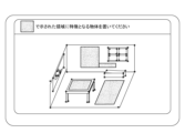
S350において、領域決定部160は、S414で決定した特徴付与推奨領域の情報を、表示部104に表示する。本実施形態では、領域決定部160は、室内の画像に特徴付与推奨領域の情報が示す領域を重畳して表示する。その場合、領域決定部160は、特徴付与推奨領域の情報が示す領域を、設定された表示態様(例えば、設定された色で表示、点滅表示等)で表示することで強調表示する。図14にS360で表示部104に表示される画面の一例を示す。図14の例では、表示部104に現実空間とCGを重畳するMR空間を描画するアプリーションが提供する画面上に、特徴付与推奨領域が強調して提示されている様子が示されている。
本実施形態では、領域決定部160は、S350で、特徴量付与推奨領域の情報を、表示部104に表示することで出力することとした。ただし、他の例として、領域決定部160は、S340で決定した特徴量付与推奨領域の情報を、印刷機等を介して、印刷媒体に印刷することで出力してもよい。また、領域決定部160は、S340で決定した特徴量付与推奨領域の情報を、設定された送信先(例えば、ユーザの保有する端末等)に送信することで出力してもよい。
In S414, the
Returning to the explanation of FIG. 3.
In S350, the
In the present embodiment, the
以上、本実施形態では、画像処理装置100は、撮像部101による撮像画像と、撮像部101のカメラパラメータと、に基づいて、撮影画像内における一つ以上の特徴それぞれに対応する現実空間における1つ以上の位置を推定することとした。そして、画像処理装置100は、推定した1つ以上の位置に基づいて、特徴が付与される領域の候補となる候補領域を決定し、候補領域で走査される探索ウィンドウの領域に含まれる特徴の個数に基づいて、特徴付与推奨領域を決定した。ユーザは、画像処理装置100が決定した特徴付与推奨領域の情報を確認することで、特徴を付与すべき領域を適切に把握できる。この結果、ユーザが現実空間に適切に特徴を付与することが可能となる。これにより、適切な位置合わせが実現されることとなる。即ち、画像処理装置100は、適切な位置合わせの実現に寄与することができる。
As described above, in the present embodiment, the
(変形例1)
本実施形態では、画像処理装置100は、特徴付与推奨領域として、平面の領域を決定した。ただし、他の例として、画像処理装置100は、ユーザが特徴を付与できる場所で、かつ、特徴が粗な領域であるならば、平面以外の領域を、特徴付与推奨領域に決定してもよい。
本変形例では、画像取得部110は、撮像部101に含まれるデプスカメラからデプスデータを取得するものとして説明する。特徴取得部130は、撮像画像から特徴を抽出すると共に、現実空間のサーフェース、又はポイントクラウド(デプスカメラが計測した現実空間上の点の集合)を特定する。候補決定部150は、このサーフェース、又はポイントクラウドを、候補領域として決定する。領域決定部160は、S412で候補領域の中で探索ウィンドウを走査させ、特徴付与推奨領域を決定することとしてもよい。
(Modification 1)
In this embodiment, the
In this modification, the
(変形例2)
本実施形態では、画像処理装置100は、S340の処理として、S401~S414の処理を実行することとした。ただし、他の例として、画像処理装置100は、例えば、撮像対象の領域(室内)の全体について設定されたサイズの探索ウィンドウを用いて、走査しつつ、S412と同様の処理で、特徴が粗な領域を決定する。そして、画像処理装置100は、決定した特徴が粗な領域のうち、設定された条件(例えば、平面領域であること等)を満たす領域を、特徴付与推奨領域を決定してもよい。
(Modification 2)
In this embodiment, the
(変形例3)
ユーザの個別の事情によっては、特徴付与推奨領域として決定される領域の中にも特徴の付与が望ましくない領域があり得る。また、特徴付与推奨領域として決定されない領域(例えば、中空の領域等)の中にも特徴の付与が望ましい領域もあり得る。
そこで、画像処理装置100は、表示部104に表示されるGUI、入力部102等を介してユーザから、特徴を付与できる領域、又は特徴の付与を許可しない領域の情報(例えば、テキスト情報等)を受付けてもよい。
その場合、画像処理装置100は、ユーザから受け付けた情報が示す特徴を付与できる領域を候補領域として決定し、特徴付与推奨領域を決定してもよい。また、画像処理装置100は、ユーザから受け付けた情報が示す特徴を付与できる領域を候補領域として決定し、特徴付与推奨領域を決定し、他の領域について、本実施形態で説明した処理を行うことで、他の領域について、特徴付与推奨領域を決定してもよい。
また、画像処理装置100は、本実施形態で説明した処理で特徴付与推奨領域を決定し、決定した特徴量付与推奨領域からユーザから受け付けた情報が示す特徴を付与できない領域を除外した領域を、最終的な特徴量付与推奨領域に決定してもよい。
(Modification 3)
Depending on the individual circumstances of the user, there may be areas in which it is not desirable to add features, even among the areas determined as recommended feature addition areas. Furthermore, there may be regions to which it is desirable to add features, even among regions (for example, hollow regions) that are not determined as recommended regions for feature addition.
Therefore, the
In that case, the
Furthermore, the
<その他の実施形態>
画像処理装置100は、各機能構成要素のうち、位置推定部140、領域決定部160等については、その代わりとして、機械学習された学習済みモデルを代わりに用いて処理してもよい。その場合、例えば、その機能構成要素への入力データと出力データとの組合せを学習データとして複数個準備されているとする。そして、画像処理装置100は、学習データから機械学習によって知識を獲得し、獲得した知識に基づいて入力データに対する出力データを結果として出力する学習済みモデルを予め生成する。このような学習済みモデルとしては、例えば、ニューラルネットワークモデル等がある。そして、その学習済みモデルは、前記処理部と同等の処理をするためのプログラムとして、CPU、GPU等と協働で動作することにより、対応する機能構成要素の処理を行う。なお、画像処理装置100は、このような学習済みモデルを、必要に応じて一定の処理後に更新してもよい。
<Other embodiments>
The
本発明は、上述の実施形態の1以上の機能を実現するプログラムを、ネットワーク又は記憶媒体を介してシステム又は装置に供給し、そのシステム又は装置のコンピュータにおける1つ以上のプロセッサがプログラムを読み出し実行する処理でも実現可能である。また、1以上の機能を実現する回路(例えば、ASIC)によっても実現可能である。 The present invention provides a system or device with a program that implements one or more functions of the embodiments described above via a network or a storage medium, and one or more processors in a computer of the system or device reads and executes the program. This can also be achieved by processing. It can also be realized by a circuit (for example, ASIC) that realizes one or more functions.
例えば、上述した画像処理装置100の機能構成の一部又は全てをハードウェアとして画像処理装置100に実装してもよい。以上、本発明の実施形態の一例について詳述したが、本発明は係る特定の実施形態に限定されるものではない。例えば、上述した各実施形態を任意に組み合わせる等してもよい。
For example, part or all of the functional configuration of the
100 画像処理装置
101 撮像部
105 制御部
100
Claims (19)
前記取得手段により取得された前記撮像画像に基づいて、前記撮像画像に含まれる一つ以上の特徴それぞれに対応する現実空間における三次元位置を推定する推定手段と、前記推定手段により推定された三次元位置に基づいて、特徴が付与される領域の候補として、現実空間に存在するオブジェクト上の平面上の領域である候補領域を決定する第1の決定手段と、
前記候補領域から、特徴が付与される領域である特徴付与推奨領域を決定する第2の決定手段と、
を有し、
前記第2の決定手段は、前記第1の決定手段により決定された前記候補領域を入力データ、前記特徴付与推奨領域を出力データとして学習した学習済みモデルにより、前記決定を行う情報処理装置。 acquisition means for acquiring an image captured by the imaging unit;
an estimation means for estimating a three-dimensional position in real space corresponding to each of one or more features included in the captured image, based on the captured image acquired by the acquisition means; and a three-dimensional position estimated by the estimation means; a first determining means that determines a candidate region that is a plane region on an object existing in real space as a candidate region to which a feature is added based on the original position;
a second determining means for determining a feature addition recommended region, which is a region to which a feature is added, from the candidate regions;
has
The second determining means is an information processing device that performs the determination using a trained model that has been trained using the candidate region determined by the first determining means as input data and the feature-adding recommended region as output data.
前記推定手段により三次元位置が推定された複数の前記特徴のうち、重複しないように選択された3つに基づいて特定される平面と、前記選択された3つ以外の特徴の三次元位置の関係に基づいて、前記現実空間に存在するオブジェクト上の平面を特定する請求項2に記載の情報処理装置。 The first determining means includes:
Among the plurality of features whose three-dimensional positions have been estimated by the estimation means, a plane specified based on three selected so as not to overlap, and the three-dimensional positions of features other than the selected three. The information processing apparatus according to claim 2, which identifies a plane on an object existing in the real space based on a relationship.
前記特徴から3つの特徴点を選択される3つの特徴の全ての組合せについて、該3つの特徴の三次元位置に基づいて特定される平面と、前記選択された3つ以外の各特徴の三次元位置との間の距離に基づいて、前記平面に含まれる特徴を取得する請求項6に記載の情報処理装置。 The first determining means includes:
For all combinations of three features for which three feature points are selected from the features, a plane specified based on the three-dimensional positions of the three features, and a three-dimensional plane of each feature other than the three selected features. The information processing apparatus according to claim 6, wherein features included in the plane are acquired based on a distance between the plane and the plane.
前記距離を計算し、前記距離が第2閾値を下回る特徴の数を、前記平面に含まれる特徴の数として取得する請求項7に記載の情報処理装置。 The first determining means includes:
The information processing apparatus according to claim 7, wherein the distance is calculated, and the number of features for which the distance is less than a second threshold is obtained as the number of features included in the plane.
前記平面に含まれる特徴の数が、定められた第3閾値以上である場合、前記平面を、前記現実空間に存在するオブジェクト上の平面として特定する請求項7に記載の情報処理装置。 The first determining means includes:
The information processing apparatus according to claim 7 , wherein when the number of features included in the plane is equal to or greater than a predetermined third threshold, the plane is identified as a plane on an object existing in the real space.
前記現実空間に存在するオブジェクト上の平面に含まれる特徴の分布に基づいて、前記特徴付与推奨領域を決定する請求項9に記載の情報処理装置。 The second determining means includes:
The information processing device according to claim 9, wherein the recommended feature addition region is determined based on a distribution of features included in a plane on the object existing in the real space.
前記現実空間に存在するオブジェクト上の平面のうち、前記推定手段によって三次元位置が推定された特徴を含まない小領域の集合を、前記特徴付与推奨領域と決定する請求項10に記載の情報処理装置。 The second determining means includes:
The information processing according to claim 10, wherein a set of small regions that do not include a feature whose three-dimensional position has been estimated by the estimating means, among planes on the object existing in the real space, are determined as the feature-adding recommended region. Device.
前記現実空間に存在するオブジェクト上の平面のうち、前記推定手段によって三次元位置が推定された特徴を含まない部分を、前記特徴付与推奨領域と決定する請求項10に記載の情報処理装置。 The second determining means includes:
The information processing apparatus according to claim 10, wherein a portion of a plane on the object existing in the real space that does not include the feature whose three-dimensional position has been estimated by the estimating means is determined as the feature addition recommended region.
前記現実空間に存在するオブジェクト上の平面のうち、前記推定手段によって三次元位置が推定された特徴が粗な部分を、前記特徴付与推奨領域と決定する請求項10に記載の情報処理装置。 The second determining means includes:
11. The information processing apparatus according to claim 10, wherein a portion of a plane on the object existing in the real space where features are rough and whose three-dimensional position is estimated by the estimating means is determined as the feature addition recommended region.
前記推定手段は、前記取得手段により取得された前記撮像画像と、前記パラメータ取得手段により取得された前記カメラパラメータと、に基づいて、前記撮像画像に含まれる一つ以上の特徴それぞれに対応する現実空間における三次元位置を推定する請求項1に記載の情報処理装置。 further comprising parameter acquisition means for acquiring camera parameters of the imaging unit,
The estimation means calculates a reality corresponding to each of one or more features included in the captured image, based on the captured image acquired by the acquisition unit and the camera parameters acquired by the parameter acquisition unit. The information processing device according to claim 1, which estimates a three-dimensional position in space.
撮像部による撮像画像を取得する取得ステップと、
前記取得ステップで取得された前記撮像画像と、に基づいて、前記撮像画像に含まれる一つ以上の特徴それぞれに対応する現実空間における三次元位置を推定する推定ステップと、
前記推定ステップで推定された三次元位置に基づいて、特徴が付与される領域の候補として、現実空間に存在するオブジェクト上の平面上の領域である候補領域を決定する第1の決定ステップと、
前記候補領域から、特徴が付与される領域である特徴付与推奨領域を決定する第2の決定ステップと、
を含み、
前記第2の決定ステップは、前記第1の決定ステップにて決定された前記候補領域を入力データ、前記特徴付与推奨領域を出力データとして学習した学習済みモデルにより、前記決定を行う情報処理方法。 An information processing method executed by an information processing device, the method comprising:
an acquisition step of acquiring an image captured by the imaging unit;
an estimation step of estimating a three-dimensional position in real space corresponding to each of one or more features included in the captured image, based on the captured image acquired in the acquisition step;
a first determining step of determining a candidate region, which is a region on a plane on an object existing in real space, as a candidate for a region to which features are to be added, based on the three-dimensional position estimated in the estimation step;
a second determining step of determining a feature addition recommended area, which is an area to which a feature is added, from the candidate areas;
including;
The second determining step is an information processing method for making the determination using a trained model that has been trained using the candidate region determined in the first determining step as input data and the feature-adding recommended region as output data.
Priority Applications (2)
| Application Number | Priority Date | Filing Date | Title |
|---|---|---|---|
| JP2019106238A JP7341736B2 (en) | 2019-06-06 | 2019-06-06 | Information processing device, information processing method and program |
| US16/893,268 US11423622B2 (en) | 2019-06-06 | 2020-06-04 | Apparatus for generating feature positions in a virtual world, information processing method, and storage medium |
Applications Claiming Priority (1)
| Application Number | Priority Date | Filing Date | Title |
|---|---|---|---|
| JP2019106238A JP7341736B2 (en) | 2019-06-06 | 2019-06-06 | Information processing device, information processing method and program |
Publications (3)
| Publication Number | Publication Date |
|---|---|
| JP2020201572A JP2020201572A (en) | 2020-12-17 |
| JP2020201572A5 JP2020201572A5 (en) | 2022-06-13 |
| JP7341736B2 true JP7341736B2 (en) | 2023-09-11 |
Family
ID=73650680
Family Applications (1)
| Application Number | Title | Priority Date | Filing Date |
|---|---|---|---|
| JP2019106238A Active JP7341736B2 (en) | 2019-06-06 | 2019-06-06 | Information processing device, information processing method and program |
Country Status (2)
| Country | Link |
|---|---|
| US (1) | US11423622B2 (en) |
| JP (1) | JP7341736B2 (en) |
Families Citing this family (2)
| Publication number | Priority date | Publication date | Assignee | Title |
|---|---|---|---|---|
| JP2022096379A (en) * | 2020-12-17 | 2022-06-29 | 富士通株式会社 | Image output program, image output method, and image output device |
| CN116309442B (en) * | 2023-03-13 | 2023-10-24 | 北京百度网讯科技有限公司 | Method for determining picking information and method for picking target object |
Citations (6)
| Publication number | Priority date | Publication date | Assignee | Title |
|---|---|---|---|---|
| JP2013225245A (en) | 2012-04-23 | 2013-10-31 | Sony Corp | Image processing device, image processing method, and program |
| JP2016004292A (en) | 2014-06-13 | 2016-01-12 | 富士通株式会社 | Terminal device, information processing system, and display control program |
| JP2017054484A (en) | 2015-09-09 | 2017-03-16 | キヤノン株式会社 | Information processing apparatus, control method of information processing apparatus, and program |
| JP2017067704A (en) | 2015-10-01 | 2017-04-06 | トヨタ紡織株式会社 | Three-dimensional shape data generation method and component inspection method using the same, as well as three-dimensional shape data generation device and component inspection program |
| JP2018091667A (en) | 2016-11-30 | 2018-06-14 | キヤノン株式会社 | Information processing device, method for controlling information processing device, and program |
| WO2018180442A1 (en) | 2017-03-31 | 2018-10-04 | オリンパス株式会社 | Inspection support device, inspection support method, and program |
Family Cites Families (6)
| Publication number | Priority date | Publication date | Assignee | Title |
|---|---|---|---|---|
| JP4956375B2 (en) * | 2007-10-30 | 2012-06-20 | キヤノン株式会社 | Image processing apparatus and image processing method |
| EP2750110B1 (en) * | 2011-08-24 | 2020-03-18 | Sony Corporation | Information processing device, information processing method, and program |
| US10452892B2 (en) * | 2013-12-17 | 2019-10-22 | Sony Corporation | Controlling image processing device to display data based on state of object in real space |
| JP6723798B2 (en) * | 2015-05-20 | 2020-07-15 | キヤノン株式会社 | Information processing device, method, and program |
| US10789622B2 (en) * | 2018-05-07 | 2020-09-29 | Adobe Inc. | Generating and providing augmented reality representations of recommended products based on style compatibility in relation to real-world surroundings |
| US11263457B2 (en) * | 2019-04-01 | 2022-03-01 | Houzz, Inc. | Virtual item display simulations |
-
2019
- 2019-06-06 JP JP2019106238A patent/JP7341736B2/en active Active
-
2020
- 2020-06-04 US US16/893,268 patent/US11423622B2/en active Active
Patent Citations (6)
| Publication number | Priority date | Publication date | Assignee | Title |
|---|---|---|---|---|
| JP2013225245A (en) | 2012-04-23 | 2013-10-31 | Sony Corp | Image processing device, image processing method, and program |
| JP2016004292A (en) | 2014-06-13 | 2016-01-12 | 富士通株式会社 | Terminal device, information processing system, and display control program |
| JP2017054484A (en) | 2015-09-09 | 2017-03-16 | キヤノン株式会社 | Information processing apparatus, control method of information processing apparatus, and program |
| JP2017067704A (en) | 2015-10-01 | 2017-04-06 | トヨタ紡織株式会社 | Three-dimensional shape data generation method and component inspection method using the same, as well as three-dimensional shape data generation device and component inspection program |
| JP2018091667A (en) | 2016-11-30 | 2018-06-14 | キヤノン株式会社 | Information processing device, method for controlling information processing device, and program |
| WO2018180442A1 (en) | 2017-03-31 | 2018-10-04 | オリンパス株式会社 | Inspection support device, inspection support method, and program |
Non-Patent Citations (1)
| Title |
|---|
| TATENO, Keisuke et al.,CNN-SLAM:Real-time dense monocular SLAM with learned depth prediction,[online],2017年,https://ieeexplore.ieee.org/document/8100178 |
Also Published As
| Publication number | Publication date |
|---|---|
| US11423622B2 (en) | 2022-08-23 |
| JP2020201572A (en) | 2020-12-17 |
| US20200388078A1 (en) | 2020-12-10 |
Similar Documents
| Publication | Publication Date | Title |
|---|---|---|
| CN109561296B (en) | Image processing apparatus, image processing method, image processing system, and storage medium | |
| CN104380338B (en) | Information processor and information processing method | |
| JP6423435B2 (en) | Method and apparatus for representing a physical scene | |
| EP2786353B1 (en) | Methods and systems for capturing and moving 3d models and true-scale metadata of real world objects | |
| US10600169B2 (en) | Image processing system and image processing method | |
| US6968084B2 (en) | Specific point detecting method and device | |
| CN106548516B (en) | Three-dimensional roaming method and device | |
| US20170214899A1 (en) | Method and system for presenting at least part of an image of a real object in a view of a real environment, and method and system for selecting a subset of a plurality of images | |
| US10930008B2 (en) | Information processing apparatus, information processing method, and program for deriving a position orientation of an image pickup apparatus using features detected from an image | |
| US9846942B2 (en) | Method and system for determining a pose of camera | |
| TWI701941B (en) | Method, apparatus and electronic device for image processing and storage medium thereof | |
| JP2011095797A (en) | Image processing device, image processing method and program | |
| JP6352208B2 (en) | 3D model processing apparatus and camera calibration system | |
| EP3804328A1 (en) | Synthesizing an image from a virtual perspective using pixels from a physical imager array | |
| JP6723798B2 (en) | Information processing device, method, and program | |
| US11490062B2 (en) | Information processing apparatus, information processing method, and storage medium | |
| JP7341736B2 (en) | Information processing device, information processing method and program | |
| JP2019003428A (en) | Image processing device, image processing method, and program | |
| JP6640294B1 (en) | Mixed reality system, program, portable terminal device, and method | |
| EP3706070A1 (en) | Processing of depth maps for images | |
| CN111291746A (en) | Image processing system and image processing method | |
| JP2015050482A (en) | Image processing device, stereoscopic image display device, image processing method, and program | |
| JP2004030408A (en) | Three-dimensional image display apparatus and display method | |
| JP6719945B2 (en) | Information processing apparatus, information processing method, information processing system, and program | |
| US10798360B2 (en) | Information processing system, method for controlling same, and program |
Legal Events
| Date | Code | Title | Description |
|---|---|---|---|
| A521 | Request for written amendment filed |
Free format text: JAPANESE INTERMEDIATE CODE: A523 Effective date: 20220602 |
|
| A621 | Written request for application examination |
Free format text: JAPANESE INTERMEDIATE CODE: A621 Effective date: 20220602 |
|
| A977 | Report on retrieval |
Free format text: JAPANESE INTERMEDIATE CODE: A971007 Effective date: 20230427 |
|
| A131 | Notification of reasons for refusal |
Free format text: JAPANESE INTERMEDIATE CODE: A131 Effective date: 20230516 |
|
| A521 | Request for written amendment filed |
Free format text: JAPANESE INTERMEDIATE CODE: A523 Effective date: 20230712 |
|
| TRDD | Decision of grant or rejection written | ||
| A01 | Written decision to grant a patent or to grant a registration (utility model) |
Free format text: JAPANESE INTERMEDIATE CODE: A01 Effective date: 20230801 |
|
| A61 | First payment of annual fees (during grant procedure) |
Free format text: JAPANESE INTERMEDIATE CODE: A61 Effective date: 20230830 |
|
| R151 | Written notification of patent or utility model registration |
Ref document number: 7341736 Country of ref document: JP Free format text: JAPANESE INTERMEDIATE CODE: R151 |