JP7340640B2 - Interoperable power supply module for servers - Google Patents
Interoperable power supply module for servers Download PDFInfo
- Publication number
- JP7340640B2 JP7340640B2 JP2022037008A JP2022037008A JP7340640B2 JP 7340640 B2 JP7340640 B2 JP 7340640B2 JP 2022037008 A JP2022037008 A JP 2022037008A JP 2022037008 A JP2022037008 A JP 2022037008A JP 7340640 B2 JP7340640 B2 JP 7340640B2
- Authority
- JP
- Japan
- Prior art keywords
- power
- pair
- electrical contacts
- clip
- power supply
- Prior art date
- Legal status (The legal status is an assumption and is not a legal conclusion. Google has not performed a legal analysis and makes no representation as to the accuracy of the status listed.)
- Active
Links
Images


Classifications
-
- G—PHYSICS
- G06—COMPUTING; CALCULATING OR COUNTING
- G06F—ELECTRIC DIGITAL DATA PROCESSING
- G06F1/00—Details not covered by groups G06F3/00 - G06F13/00 and G06F21/00
- G06F1/16—Constructional details or arrangements
- G06F1/18—Packaging or power distribution
- G06F1/183—Internal mounting support structures, e.g. for printed circuit boards, internal connecting means
- G06F1/188—Mounting of power supply units
-
- H—ELECTRICITY
- H05—ELECTRIC TECHNIQUES NOT OTHERWISE PROVIDED FOR
- H05K—PRINTED CIRCUITS; CASINGS OR CONSTRUCTIONAL DETAILS OF ELECTRIC APPARATUS; MANUFACTURE OF ASSEMBLAGES OF ELECTRICAL COMPONENTS
- H05K7/00—Constructional details common to different types of electric apparatus
- H05K7/14—Mounting supporting structure in casing or on frame or rack
- H05K7/1485—Servers; Data center rooms, e.g. 19-inch computer racks
- H05K7/1488—Cabinets therefor, e.g. chassis or racks or mechanical interfaces between blades and support structures
- H05K7/1492—Cabinets therefor, e.g. chassis or racks or mechanical interfaces between blades and support structures having electrical distribution arrangements, e.g. power supply or data communications
-
- H—ELECTRICITY
- H05—ELECTRIC TECHNIQUES NOT OTHERWISE PROVIDED FOR
- H05K—PRINTED CIRCUITS; CASINGS OR CONSTRUCTIONAL DETAILS OF ELECTRIC APPARATUS; MANUFACTURE OF ASSEMBLAGES OF ELECTRICAL COMPONENTS
- H05K7/00—Constructional details common to different types of electric apparatus
- H05K7/20—Modifications to facilitate cooling, ventilating, or heating
-
- G—PHYSICS
- G06—COMPUTING; CALCULATING OR COUNTING
- G06F—ELECTRIC DIGITAL DATA PROCESSING
- G06F1/00—Details not covered by groups G06F3/00 - G06F13/00 and G06F21/00
- G06F1/16—Constructional details or arrangements
- G06F1/18—Packaging or power distribution
- G06F1/189—Power distribution
-
- H—ELECTRICITY
- H02—GENERATION; CONVERSION OR DISTRIBUTION OF ELECTRIC POWER
- H02J—CIRCUIT ARRANGEMENTS OR SYSTEMS FOR SUPPLYING OR DISTRIBUTING ELECTRIC POWER; SYSTEMS FOR STORING ELECTRIC ENERGY
- H02J7/00—Circuit arrangements for charging or depolarising batteries or for supplying loads from batteries
-
- H—ELECTRICITY
- H05—ELECTRIC TECHNIQUES NOT OTHERWISE PROVIDED FOR
- H05K—PRINTED CIRCUITS; CASINGS OR CONSTRUCTIONAL DETAILS OF ELECTRIC APPARATUS; MANUFACTURE OF ASSEMBLAGES OF ELECTRICAL COMPONENTS
- H05K5/00—Casings, cabinets or drawers for electric apparatus
- H05K5/02—Details
- H05K5/0217—Mechanical details of casings
-
- H—ELECTRICITY
- H05—ELECTRIC TECHNIQUES NOT OTHERWISE PROVIDED FOR
- H05K—PRINTED CIRCUITS; CASINGS OR CONSTRUCTIONAL DETAILS OF ELECTRIC APPARATUS; MANUFACTURE OF ASSEMBLAGES OF ELECTRICAL COMPONENTS
- H05K7/00—Constructional details common to different types of electric apparatus
- H05K7/02—Arrangements of circuit components or wiring on supporting structure
-
- H—ELECTRICITY
- H05—ELECTRIC TECHNIQUES NOT OTHERWISE PROVIDED FOR
- H05K—PRINTED CIRCUITS; CASINGS OR CONSTRUCTIONAL DETAILS OF ELECTRIC APPARATUS; MANUFACTURE OF ASSEMBLAGES OF ELECTRICAL COMPONENTS
- H05K7/00—Constructional details common to different types of electric apparatus
- H05K7/14—Mounting supporting structure in casing or on frame or rack
- H05K7/1485—Servers; Data center rooms, e.g. 19-inch computer racks
- H05K7/1487—Blade assemblies, e.g. blade cases or inner arrangements within a blade
Description
開示する実施形態は、一般的に、サーバ、特に、限定しないが、データセンタに位置するサーバラック内のサーバに電力を供給するための回転電力供給モジュールに関する。 TECHNICAL FIELD The disclosed embodiments relate generally to rotating power supply modules for powering servers, and more particularly, but not limited to, servers in server racks located in data centers.
クラウドコンピューティングセンタ等の現代のデータセンタは、サーバ、ブレードサーバ、ルータ、エッジサーバ等の大量の情報技術(IT)機器を収納する。これら個々のIT機器は通常、各ラック内の複数のIT機器を備えたコンピューティングセンタ内のラックに収納される。ラックは通常、データセンタ内のクラスタにグループ化される。 Modern data centers, such as cloud computing centers, house large amounts of information technology (IT) equipment such as servers, blade servers, routers, edge servers, etc. These individual IT devices are typically housed in racks within a computing center with multiple IT devices in each rack. Racks are typically grouped into clusters within a data center.
パブリッククラウドサービスおよびプライベートクラウドサービスの両方において、サービスプロバイダは、同一データセンタ内の1つのデータセンタクラスタから他のクラスタへサーバを移転する必要があったり、あるいは、異なる地理的位置の1つのデータセンタサイトから他のデータセンタサイトへとサーバを移転し、移行する必要があったりする。サーバの移転は、異なるデータセンタのラック間で移動させることを意味し、同一データセンタ内の異なるクラスタは異なる種類のラックを使用しうる。これは、IT機器の設計は実装されるラックと互換でなければならないから、困難である。 In both public and private cloud services, service providers may need to relocate servers from one data center cluster to another within the same data center, or from one data center cluster in a different geographic location. There may be a need to move and migrate servers from one site to another data center site. Relocating a server means moving it between racks in different data centers, and different clusters within the same data center may use different types of racks. This is difficult because the design of the IT equipment must be compatible with the rack in which it is installed.
多くの異なるラック構成があるが、ラック標準において大きな構成の違いが存在しうるOCPオープンラック、ODCCスコルピオラック等を含む業界標準がある。ラックは、形状因子、電力供給設計、冷却方法等が異なる。これは、サーバ等のIT機器は、多種多量のラックに収納する前に複数のラック仕様と互換でなければならないことを意味する。互換でなければ、IT機器は実装が難しく、様々な種類のラックで適切に機能しないかもしれない。これは、サーバおよびシステム設計を大幅に限定し、OEMベンダ、ラックベンダ、サーバベンダ、部品供給者およびエンドユーザにとって課題である。ハードウエアコストは、クラウドサービスビジネスおよびインターネットサービスビジネスにとってクリティカルであり、相互運用性は、ハードウエアコストを低減するために重要な特徴である。以前のIT機器設計は、1つあるいは少数のラックの種類でのみ、設計が使用可能である。この相互運用性の欠如は、大きな不足である。 Although there are many different rack configurations, there are industry standards including OCP open racks, ODCC Scorpio racks, etc. where there can be large configuration differences in rack standards. Racks differ in form factors, power supply designs, cooling methods, etc. This means that IT equipment such as servers must be compatible with multiple rack specifications before being housed in a large number of different types of racks. Without compatibility, IT equipment may be difficult to implement and may not function properly in different types of racks. This significantly limits server and system design and is a challenge for OEM vendors, rack vendors, server vendors, component suppliers, and end users. Hardware costs are critical for cloud service businesses and Internet service businesses, and interoperability is an important feature to reduce hardware costs. Previous IT equipment designs have only been available in one or a few rack types. This lack of interoperability is a major shortfall.
本開示の一態様は、互いに平行な第1の面と第2の面とを有し、前記第1の面に対して垂直な第1の軸を中心に第1の向きと第2の向きの間で回転可能な電力供給ボード(PDB)と、前記第1の面上に位置決めされ、第1の負接点と隣接する第1の正接点を有する電気接点の第1の対と、前記第1の面上に位置決めされ、前記電気接点の第1の対とは間隙を介しており、第2の正接点および第2の負接点を有する電気接点の第2の対と、前記電力供給ボードに接続され、前記電気接点の第1の対または前記電気接点の第2の対と電気的に接続するように適合される1対の電力クリップを有し、前記第1の軸とは平行で、間隙を介した第2の軸を中心に回転可能であり、前記1対の電力クリップが前記電気接点の第1の対に電気的に接続される第1の位置と、前記1対の電力クリップが前記電気接点の第2の対に電気的に接続される第2の位置との間で回転可能である電力クリップモジュールと、を具備する電力供給モジュールである。 One aspect of the present disclosure has a first surface and a second surface parallel to each other , and has a first orientation and a second orientation centered on a first axis perpendicular to the first surface. a power delivery board (PDB) rotatable between; a first pair of electrical contacts having a first positive contact positioned on the first side and adjacent a first negative contact; a second pair of electrical contacts positioned on a surface of the power supply board and spaced apart from the first pair of electrical contacts and having a second positive contact and a second negative contact; a pair of power clips connected to and adapted to electrically connect with the first pair of electrical contacts or the second pair of electrical contacts, parallel to the first axis; , a first position rotatable about a second axis with a gap therebetween, wherein the pair of power clips are electrically connected to the first pair of electrical contacts; a power clip module rotatable to and from a second position where the clip is electrically connected to the second pair of electrical contacts.
以下の図を参照し、本発明の限定しない、非包括的な実施形態を説明する。同じの参照符号は、特に指定しない限り、図全体において同じ部品を指す。 Non-limiting, non-exhaustive embodiments of the invention will now be described with reference to the following figures. Like reference numbers refer to like parts throughout the figures, unless otherwise specified.
ITラックにおいて、IT機器に電力を供給する回転電力供給モジュールの実施形態を説明する。詳細は、実施形態を理解するために説明するが、当業者は、他の方法、構成要素、材料等の1つ以上がなくても本発明が実施できることは認識できる。いくつかの例において、周知の構造、材料および動作は、詳細に示されていない、あるいは、説明されていないが、それでも本発明の範囲に含まれる。 An embodiment of a rotating power supply module that supplies power to IT equipment in an IT rack will be described. Although details are described to provide an understanding of the embodiments, those skilled in the art will recognize that the invention may be practiced without one or more other methods, components, materials, etc. In some instances, well-known structures, materials and operations are not shown or described in detail, but are still within the scope of the invention.
明細書における「一実施形態」あるいは「実施形態」という記述は、記載される特徴、構造あるいは特性が、少なくとも1つの実施形態に含まれうることを意味し、出現する「一実施形態において」または「実施形態において」は、必ずしもすべてが同じ実施形態を参照しているわけではない。さらに、特定の特徴、構造、または特性は、1つ以上の実施形態において適切に組み合わせてもよい。本願で使用されているように、「前」、「後」、「上」、「下」、「側」、「横」、「縦」等の方向の用語は、図面において提示される実施形態の向きを指すが、方向の用語は、実際の使用時に記載する実施形態の特定の向きを暗示する、あるいは要求すると解釈すべきではない。 References in the specification to "one embodiment" or "an embodiment" mean that the described feature, structure, or characteristic can be included in at least one embodiment; The terms "in an embodiment" are not necessarily all referring to the same embodiment. Furthermore, the particular features, structures, or characteristics may be combined as appropriate in one or more embodiments. As used herein, directional terms such as "front", "rear", "top", "bottom", "side", "lateral", "portrait" and the like refer to the embodiments presented in the drawings. However, directional terminology should not be construed to imply or require a particular orientation of the described embodiments in actual use.
回転可能な電力分配ボードおよび回転可能な電力クリップモジュールを有する回転可能な電力供給モジュールの実施形態を以下に説明する。電力分配ボードは、サーバシャシーに対して回転可能であり、電力クリップモジュールは、電力分配ボードに対して回転可能である。安全ピンまたはネジは、電力供給モジュールを適切な向きに確実に保持するために用いられる。これらの2つの要素の組み合わせた回転は、電力クリップモジュールが異なるバスバ構造と異なるラック内の位置を一致させることを可能とし、また、対応する正および負の接続をバスバ設計と確実に一致させる。動作において、電力供給ボードは180度回転し、電力クリップモジュールは180度回転する。これら2つの180度の回転は、電力モジュールが異なるラック電力構造と一致するように調整されることを可能とする。したがって、実施形態は、サーバとラックの相互運用性を向上させ、サーバ電力供給システム位置の動的調整を可能とし、サーバシャシー内のより良好な気流の形成を支援する。また実施形態は、特に、道具なしで動作され、すなわち、実施形態は、動作またはサービス提供のための物理的なハードウエアツールを必要としないから、電力供給設計のサービス性も向上させる。さらにサービス性を向上させるため、あるいはサービスの必要性を低減させるため、実施形態は、不適切な動作を防止する機能を有する。 Embodiments of rotatable power supply modules having rotatable power distribution boards and rotatable power clip modules are described below. The power distribution board is rotatable relative to the server chassis and the power clip module is rotatable relative to the power distribution board. Safety pins or screws are used to securely hold the power supply module in the proper orientation. The combined rotation of these two elements allows the power clip module to match different busbar structures and locations in different racks, and also ensures corresponding positive and negative connections match the busbar design. In operation, the power supply board rotates 180 degrees and the power clip module rotates 180 degrees. These two 180 degree rotations allow the power module to be adjusted to match different rack power configurations. Thus, embodiments improve server and rack interoperability, enable dynamic adjustment of server power supply system positions, and assist in creating better airflow within the server chassis. Embodiments also improve the serviceability of the power supply design, particularly since they are operated without tools, ie, embodiments do not require physical hardware tools for operation or servicing. To further improve serviceability or reduce the need for service, embodiments include functionality to prevent inappropriate operation.
電力供給モジュール(PDM)の実施形態は、PDMシャシーに統合され、PDMシャシーは、ITシャシーに統合され、固定される。PDMは、2組の電力接続を備えた電力供給ボード(PDB)を有し、電力接続の各組は、PDBにパッケージ化された電力電子機器に接続される。電力接続の各組は、1つの正接続および1つの負接続を有する。電力クリップモジュールは、PDBに取り付けられる。電力クリップモジュールは、電力クリップと共に電力コネクタとパッケージ化され、これらの電力コネクタおよびクリップは、ラック電力バスバとPDBの間の電気回路を接続する。クリップモジュールの一部は、電流を伝導するために設計され、クリップモジュールの一部は絶縁され、非導電性である。クリップモジュールの導電部分は、PDBの電力接続のいずれかの組に接続し、PDBおよび対応する電力電子機器に接続する。PDBは180度回転され、クリップモジュールは180度回転され、PDMは異なるラック構成の間で相互運用可能である。 An embodiment of a power delivery module (PDM) is integrated into a PDM chassis, and the PDM chassis is integrated and fixed to an IT chassis. A PDM has a power delivery board (PDB) with two sets of power connections, each set of power connections connected to power electronics packaged in the PDB. Each set of power connections has one positive connection and one negative connection. A power clip module is attached to the PDB. The power clip module is packaged with power connectors along with power clips that connect electrical circuits between the rack power bus bar and the PDB. A portion of the clip module is designed to conduct current, and a portion of the clip module is insulated and non-conductive. The conductive portions of the clip module connect to either set of power connections on the PDB and to the PDB and corresponding power electronics. The PDB is rotated 180 degrees, the clip module is rotated 180 degrees, and the PDM is interoperable between different rack configurations.
図1は、データセンタで共通に用いられるITコンテナの種類である電子機器ラックの実施形態の側面図を示すブロック図である。実施形態において、電子機器ラック100は、CDI101、ラック管理ユニット(RMU)102、1つ以上のサーバブレード103A~103D(集合的にサーバブレード103と呼ぶ)を有する。サーバブレード103は、電子機器ラック100の前端104それぞれからサーバスロットのアレイに挿入可能である。なお、4つのサーバブレード103A~103Dのみを図示しているが、それより多くの、あるいは少ないサーバブレードを電子機器ラック100内に保持できる。また、CDU101、CMU102およびサーバブレード103の特定の位置は、例示の目的のためだけに示しており、CDU101、CMU102およびサーバブレード103の他の配置あるいは構成も実施可能である。さらに、前端104に配置されるフロントドアおよび後端105に配置されるバックドアは任意である。いくつかの実施形態において、前端104および/または後端105にドアがなくてもよい。
FIG. 1 is a block diagram illustrating a side view of an embodiment of an electronic equipment rack, a type of IT container commonly used in data centers. In embodiments, electronics rack 100 includes a CDI 101, a rack management unit (RMU) 102, and one or more server blades 103A-103D (collectively referred to as server blades 103). A
一実施形態において、CDU101は、熱交換器111、液体ポンプ112およびポンプコントローラ110を有する。熱交換器111は、液体間熱交換器である。熱交換器111は、外部液体供給/戻り配管131~132に接続され、一次ループを形成する液体コネクタの第1の対を有する第1チューブを有し、外部液体供給/戻り配管131~132に接続されるコネクタは、電子機器ラック100の後端105に配置または装着される。また、熱交換器111はさらに、液体分岐管125に接続される液体コネクタの第2の対を有する第2チューブを有し、液体分岐管125は、サーバブレード103に冷却液を供給する供給分岐管と、CDU101に戻る温まった液体を戻す戻り分岐管とを有する。プロセッサは、冷却板に装着され、冷却板は、中に埋め込まれ、液体分岐管125から冷却液を受け取り、プロセッサから液体分岐管125に戻って交換される熱を伝達する冷却液を戻す液体分配溝を有する。ラック100は、図3A以降で示されるような電力供給モジュールの実施形態を使用可能なITラックの一例である。
In one embodiment, CDU 101 includes a
各サーバブレード103は、1つ以上のIT構成要素(たとえば、CPU、GPU、メモリ、および/または記憶装置)を有する。各IT構成要素は、データ処理タスクを実行し、IT構成要素は、記憶装置にインストールされ、メモリにロードされ、1つ以上のプロセッサにより実行されてデータ処理タスクを実行するソフトウエアを有する。サーバブレード103は、1つ以上の計算サーバ(計算ノードとも呼ばれる)に接続されるホストサーバ(ホストノードと呼ばれる)を有する。ホストサーバ(1つ以上のCPUを有する)は通常、ネットワーク(たとえば、インターネット)においてクライアントとインタフェース接続し、ストレージサービス(たとえば、バックアップおよび/または復元等のクラウドベースストレージサービス)等の特定のサービスの要求を受信し、アプリケーションを実行して特定の動作(たとえば、サービスとしてのソフトウエアまたはSaaSプラットフォームの一部としての画像処理、ディープデータラーニングアルゴリズムまたはモデリング等)を実行する。要求に応答して、ホストサーバは、ホストサーバにより管理される1つ以上の計算サーバ(1つ以上のGPUを有する)にタスクを分散させる。計算サーバは実際のタスクを実行し、これにより動作中に熱が発生する。
Each
電子機器ラック100はさらに、サーバブレード103およびCDU101に供給される電力を供給、管理するRMU102を有する。RMU102は、電力供給ユニット(不図示)に接続され、電力供給ユニットの他の熱管理(たとえば、冷却ファン)と共に、電力供給ユニットの電力消費を管理する。電力供給ユニットは、電子機器ラック100の残りの部品に電力を供給する必要な回路(たとえば、交流(AC)直流(DC)、または、DCDC電力変換器、電池、変圧器あるいは調整器等)を有する。
The
一実施形態において、RMU102は、最適制御ロジック111とラック管理コントローラ(RMC)122を有する。最適制御ロジック111は、サーバブレード103の少なくとも一部に接続され、プロセッサのプロセッサ温度、液体ポンプ112の現在ポンプ速度、冷却液の液体温度等、各サーバブレード103の動作状態を受信する。この情報に基づいて、最適制御ロジック111は、目的関数の出力が最大に到達すると共に、一連の所定の制約を満たすように、所定の目的関数を最適化することにより、液体ポンプ112の最適ポンプ速度を決定する。最適ポンプ速度に基づいて、RMC122は、ポンプコントローラ110に信号を送信し、最適ポンプ速度に基づいて液体ポンプ112のポンプ速度を制御する。
In one embodiment,
図2A~2Bは、情報技術(IT)ラックのバスバの実施形態を示す。図2Aおよび図2Bは共に、後部から見たラックを示す。図2Aは、垂直のスタックにおいて収納される1つ以上のIT機器202を有するラック200の実施形態を示す。IT機器202は、下記において主にサーバとして記載するが、様々な実施形態において、IT機器202は、ラックに収納可能な任意の種類のIT機器であり、たとえば、サーバ、グラフィックス処理ユニット(GPU)、電力ユニット、電池バックアップ(BBU)ユニット、電力供給ユニット(PSU)、冷却ユニット、あるいは、これらのいくつかの組み合わせである(たとえば、図1を参照)。ラック内のすべてのIT機器、あるいは、ラックに収納可能なすべてのIT機器に電力を供給するため、バスバ204はラックの下から上までのほぼ高さ全体に延設される。バスバ204は、電気接点として機能する2つのバー、正極(+)バーおよび負極(-)バーを有する。ラックの後部から見て、正極バーが右側で、負極バーが左側であるのは業界標準である。実施形態において、バスバ204は、後部から見てラックの右側近くの、ラック中心線の右に位置する。
2A-2B illustrate an embodiment of a bus bar for an information technology (IT) rack. Figures 2A and 2B both show the rack from the rear. FIG. 2A shows an embodiment of a
図2Bは、ラック250の実施形態を示す。ラック250は、あらゆる点でラック200に類似しており、垂直のスタックにおいて収納される1つ以上のサーバ202を有し、ラックの下から上までのほぼ高さ全体に延設され、ラック内に収納された、または収納可能なすべてのサーバに電力を供給するバスバ254を有する。バスバ204と同様に、バスバ254は、電気接点として機能する2つのバー、正極(+)バーおよび負極(-)バーを有し、ラックの後部から見て、正極バーが右側で、負極バーが左側である。ラック200とラック250の主な違いは、バスバの位置である。バスバ254が、ラックの中心線の右ではなく、ほぼラックの中心線に沿って位置する。IT機器202がラック200からラック250へ、あるいは、その逆に容易に移動することを可能とするため、サーバ202またはラックは、異なるバスバ位置に適合可能な電力供給モジュールを有さなければならない。
FIG. 2B shows an embodiment of a
図3A~3Fは、電力供給モジュール300の実施形態を示す。図3A~3Bは、組み立てた電力供給モジュールを示す。電力供給モジュール300は、電力供給ボード302と電力クリップモジュール310の2つの主要要素を有する。
3A-3F illustrate an embodiment of a
電力供給ボード302は、第1の面S1(図3Aを参照)および第2の面S2(図3Bを参照)を有する。一実施形態において、第1の面S1および第2の面S2は平面であり、互いにほぼ平行で、ボード302の厚さ分だけ互いに離れている。一実施形態において、ボード302は印刷回路基板であるが、他の実施形態において、他の種類のボードでもよい。実施形態において、位置決めネジまたはピン301を使用して、電力供給モジュール(PDM)シャシーにボード302を取り付けて保持し、電力供給モジュール300を特定の向きに保持する(図4A~4Bを参照)。他の実施形態において装着方法は異なってもよく、位置決めネジ301はわずかに異なっていてもよい。あるいは、いくつかの適用において、不要である。
ボード302は、第1の軸Aを中心に回転可能である。実施形態において、第1の軸A1は、ボード302の面に対してほぼ垂直であり、ボードのほぼ中央(すなわち、W1=W2)であるが、他の実施形態において、第1の軸A1はボード302の平面内に対して垂直である必要はなく、また、ボードの中央に位置する必要はない(すなわち、W1≠W2)。位置決めネジ301および出力コネクタ304は、軸A1の中心であり、第2の面S2に装着され、出力コネクタ304は、サーバのようなIT機器のメインボードに電力供給モジュール300を接続するために使用される(例えば、図4A~4Bを参照)。
ボード302の第1の面S1は、第1の負接点(1-)および第1の正接点(1+)を有する、間隙を介した電気接点の第1の対と、第2の負接点(2-)および第2の正接点(2+)を有する、間隙を介した電気接点の第2の対の2つ対の電気接点を有する。他の実施形態において、電気接点の対ごとに、負接点および正接点は、単一モジュールとして包括される。
The first side S1 of the
図3Cでよくわかるように、クリップ装着モジュール308は、ボードの平面に垂直なボード302に形成、あるいは取り付けられ、装着溝は、電気接点の2つの対それぞれの正および負電気接点の間に位置決めされる。クリップ装着溝308は、クリップモジュール310を回転可能に収容し、クリップモジュールがクリップモジュールのクリップ装着溝および/またはシャフトにより定義される第2の軸A2を中心に回転可能となるように設計される。実施形態において、第2の軸A2は、第1の軸A1とほぼ平行であり、非ゼロの距離W3の分だけ、第1の軸から離れている。一般的に、W3は、電力供給モジュールが使用される2つのラック構成において、バスバ間の距離の半分であることが望ましい。たとえば、図2A~2Bで示されるラック構成で使用するための実施形態において、W3は、図2の右側のバスバと図2Bの中央のバスバの間の距離の半分である。
As best seen in FIG. 3C, the
電力クリップモジュール310は、バスバに電気的に接続する電力クリップ318+と318―の対と、電力クリップ318+および318-をボード302の電気接点の対の一方、すなわち、1+/1-または2+/2-の一方に電気的に接続する1対の接触パッド314+および314-の2つの主要部分を有する。電力クリップおよび接触パッドに加えて、電力クリップ310は、位置決めネジ309と位置決めナット311を有する。電力クリップモジュール310は、位置決めネジ309および位置決めナット311を使用して、電力供給ボード302に取り付けられる。位置決めネジ309がクリップ装着溝308に挿入され、電力クリップモジュール310が回転可能なシャフトとして機能する。位置決めネジ309および位置決めナット309は、ボード302に取り付けられた電力クリップモジュール310を保持し、ネジはナットに挿入され、締め付けられてクリップモジュール310およびボード302を保持する。一実施形態において、位置決めナット311は、バネのような可撓性構造を有し、クリップモジュール310が回転動作中に部分的に引っ張られ、クリップモジュールを場所に戻す自動的な弾性を与え、ボードとクリップモジュールを締め付ける。クリップモジュール310の詳細は、図3D~3Eに関連して後述する。
図3Cは、ボード302上の電気接点の対の位置決めを最適に示す。電力供給ボードは、ITシャシー内に垂直に実装され(図4A~4Bを参照)、したがって、図はサーバの後部から見たPDBの図である。上述したように、第1の面S1は、第1の負接点(1-)および第1の正接点(1+)を有する、水平に間隙を介した電気接点の第1の対を有する。また、第1の面S1には、第2の負接点(2-)および第2の正接点(2+)を有する、水平に間隙を介した電気接点の第2の対を有する。電気接点の第1の対および第2の対は、ボード上で垂直に離間され、第1の正接点1+は第2の負接点2-の真上であり、第1の負接点1-は第2の正接点2+の真上である。言い換えれば、第1の正接点1+は、第2の正接点2+の対角線上にあり、第1の負接点1-は、第2の負接点2-の対角線上にある。クリップ装着モジュール308は、ボード302内で電気接点の対の間に位置決めされ、4つの電気接点およびクリップ装着モジュールは、5点形を形成する。
FIG. 3C best illustrates the positioning of pairs of electrical contacts on
図3D~3Eは、電力クリップモジュール310の実施形態を示す。図3Dは、平面図である。図3Eは、断面図である。電力クリップモジュール310は、バスバと電力供給モジュール300の電気接点の間の電気的接続を形成する。電力クリップモジュール310は、第1の面CS1および第2の面CS2を有するクリップモジュール基板312を有する。クリップモジュール基板は、硬質な材料から作成され、一実施形態において、たとえば、硬質な電気的絶縁材料から作成される。他の実施形態において、クリップモジュール基板312は、導電性材料から作成され、接触パッドおよび電力クリップを相互に電気的に絶縁する。実施形態において、クリップモジュール基板312は円形であるが、他の実施形態において、四角形のように異なる形状を有する(たとえば、図3Gを参照)。
3D-3E illustrate an embodiment of a
電力クリップモジュール310がボード320上に実装されると、第1の面CS1はボードに対向する(図3Bを参照)。電気接点の第1の対1+/1-、または電気接点の第2の対2+/2-の一方と電気的に接触するため、正接触パッド314+および負接触パッド314-は、第1の面CS1内、あるいは第1の面CS1上に形成される。電力クリップ318の対は、第2の面CS2上に形成され、正クリップ318+は正接触パッド314+に電気的に接続され、負電力クリップ318-は、負接触パッド314-に電気的に接続される。電力クリップ318+および318-と同様に、正接触パッド314+および負接触パッド314-は、互いに電気的に絶縁される。また、クリップモジュール基板312は孔320を有し、ネジ/シャフト309を収容し、シャフトを中心に回転する。実施形態において、正接触パッド314+および負接触パッド314-は、円形のパイ形状部分であり、それぞれ、ほぼ円の4分の1であるが、他の実施形態では、正接触パッド314+および負接触パッド314-は他の形状を有する(たとえば、図3Gを参照)。本配置で、電力クリップ318+および318-は所定の時間に、接触パッド314+および314-を介して、ボード302上の電気接点の1つの対、すなわち、電気接点の第1の対1+/1-あるいは電気接点の第2の対2+/2-のいずれかにのみ、電気的に接続される。
When the
正電力クリップを正バスバ接点に、負電力クリップを負バスバ接点に(図4Bを参照)、適切に確実に接続する安全機能として、電力クリップモジュール310は、作業者に電力クリップモジュールの正しい向きを示す視覚的表示器である実装シンボル322を有する。実施形態において、実装シンボル322は、電力クリップモジュールが正しく向いている場合、上向きを指す矢印(すなわち、ラックの上部に向かう)である。しかし、他の実施形態において、もちろん、同じ、または異なる向きの視覚的表示器の他の種類も使用できる。
As a safety feature to ensure proper connection of the positive power clip to the positive busbar contact and the negative power clip to the negative busbar contact (see Figure 4B), the
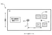
図3Fは、電力分配ボード302上の部品間の電気的接続を示す。電力調整電子機器306は、第1の面S1または第2の面S2の一方に装着される。実施形態において、電力調整電子機器は、第1の面S1上に装着され、S1の図において実線で示される。電力調整電子機器は、出力コネクタ304を介してIT機器に出力される前に、電気接点の2つの対の一方(1+/1-または2+/2-)でバスバから受電する電力を調整する。様々な実施形態において、電力調整電子機器306は、電圧調整器、整流器、あるいは他の電力調整および制御要素を有する。
FIG. 3F shows the electrical connections between components on the
電力調整電子機器306が電気接点1+/1-または電気接点2+/2-から受電する電力を確実に調整するため、ボード302は、電気接点の第1および第2の対を電力調整電子機器に電気的に接続し、電気接点の各対が電力電子機器に経路指定する回路を有するように、配線または接続を有する。実施形態において、実線で示される配線対T1は、実線で示されるように、接点の第1の対1+/1-を電力電子機器に電気的に接続する。配線対T1は、接点1+に接続される配線T1+と、接点1-に接続される配線T1-を有する。同様に、破線で示される面S2の配線対T2は、破線で示されるように、接点の第2の対2+/2-を電力電子機器に電気的に接続する。配線対T2は、接点2+に接続される配線T2+と、接点2-に接続される配線T2-を有する。他の実施形態において、配線対T1およびT2は、同じ側、あるいは異なる側、もしくは、電力供給ボード302において均一である。さらに、電力クリップモジュール310の動作は、任意の時間において、接点の2つの対の一方のみ(第1の対1+/1-あるいは第2の対2+/2-)が電力電子機器に電力を確実に向ける。出力コネクタ304は、ボード302の向きにかかわらず、PDBをIT機器のメインボードに接続するために使用されるから(図4A~4Bを参照)、配線324の単一の対のみが電力電子機器およびコネクタ304の間で必要である。
To ensure that
図3Gは、電力供給モジュール350の他の実施形態を示し、クリップモジュールの回転を支援するいくつかの補助構造は図において示されていない。電力供給モジュール350は、電力供給モジュール300とほぼ類似している。電力供給モジュール350および300の主な違いは、電力クリップモジュールの構成である。電力供給モジュール350は、円形ではなく、四角形の電力クリップモジュール352を有する。四角形であるから、電力クリップモジュール352も四角形の接触パッドを有する。電力クリップモジュール352は、ボード302上の電気接点の両方の対の両方の対(1+/1-および2+/2-)を完全に覆っていて、適切に位置合わせしているか見ることは困難である。この課題に対処するため、システムの実装を容易にし、信頼性を向上させるため、電力クリップモジュール352は、クリップの2つの面上に変位緩衝材354を有する。追加の実施形態において、電力クリップモジュールは、異なる形状因子にパッケージ化され、複数のクリップモジュールが電力供給ボード上に配置される。
FIG. 3G shows another embodiment of a
図4A~4Bは、モジュール300のような電力供給モジュールを有するサーバ等のIT装置400の実施形態を示す。図4Aは平面図、図4Bは側面図である。IT装置400は、中に収納されるメインボード404を備えたITシャシー402を有する。様々な実施形態において、メインボード404は、IT装置400の機能を実行する複数の電子構成要素(不図示)を有する。
4A-4B illustrate an embodiment of an
電力供給モジュール(PDM)シャシー406も、ITシャシー402内に位置決めされ、電力供給モジュール300等の電力供給モジュールを収容し、保持する(図3A~3Fを参照)。PDMシャシーは、システム実装の支持(すなわち、構造の装着および固定)を含む、電力モジュール全体の構造的支持を与える。一実施形態において、PDMシャシー406は、電力供給ボード302の端および装着/位置決めネジ301を係止するフレームであるが、他の実施形態において、PDMシャシーは異なる構成である。PDMシャシー406は、支持物408(図4において可視)によりITシャシー402に固定され、PDMシャシー406はITシャシー402に対して固定である。PDMシャシー406は、ITシャシー402の後部に位置決めされ、電力クリップモジュール310の電力クリップは、ITシャシーの背面から突出し、IT装置400が配置されるラックのバスバに接続される。PDMシャシー406も位置決めされ、電力供給モジュール300を垂直に、すなわち、垂直に位置決めされたボード302の平面で、あるいは、水平に位置決めされた軸A1およびA2で保持する。そのため、図5A~5Cで示すように異なる向きの間で回転可能であり、電力クリップモジュールを、異なるバスバを係止可能な異なる位置に移動させる。
A power delivery module (PDM)
電力供給モジュール300は、出力コネクタ304とメインボードの間に接続されるワイヤ408を使用して、メインボード404に電気的に接続される。その結果、電力供給モジュール300がある向きから他の向きに移動された場合(たとえば、図5A~5Cを参照)、ケーブルまたは1つ以上のワイヤ408はねじれる。しかし、回転可能な出力コネクタ304の中央位置は、408に対する断裂を確実に最小とし、メインボード404への電力接続の断裂を最小とする。他の実施形態において、ケーブル/ワイヤ接続は、直接ブラインド結合または他の技術により省くことが可能である。
図5A~5Cは、電力供給モジュール300のような電力供給モジュールの動作の実施形態を示す。これらの図は、ラックの後部からの図である。実施形態において、電力供給モジュール300は、ボード302およびPDMシャシーに垂直な軸A1で、PDMシャシー406に回転可能に取り付けられる。また、上述したように、クリップモジュール310はボード302に回転可能に接続され、軸A1と平行な軸A2を中心に回転する。
5A-5C illustrate embodiments of the operation of a power supply module, such as
図5Aは、図2Aに示すように、後ろから見たときにバスバがラックの右側であるラックで使用するのに適した電力供給モジュール300の位置を示す。この位置において、電力供給モジュールは、ボード302の面S1上の電気的接点1+および1-に電気的に接続される電力クリップにより、バスバに接続される。バスバがラックの中央にある(図2Bを参照)ラックでサーバを使用可能とするため、電力供給モジュール300は、図5Aで示す位置から図5Bで示す位置へと、軸A1を中心に180度回転される。PDMシャシー406は固定であり、したがって、電力供給モジュール300と回転しない。
FIG. 5A shows a position of the
図5Bに示す位置において、電力クリップモジュール310の電力クリップは、中央のバスバと接触可能となる位置に移動するが、図5Aおよび図5Bの間での電力供給モジュール300の回転は、誤った電気接点の組であるから、電気接点1+および1-に電気的に接続したまま、バスバへの適切な正・正および負・負の電気的接続とする。電力クリップを向けなおし、正しい向きとして正しい電気接点(すなわち、図5Bの接点2+/2-)に接続するため、電力クリップモジュール310は、図5Bの位置から図5Cの位置に180度回転され、実装シンボルが上向きに指した状態となる。図5Cの向きにおいて、電力クリップは正しい位置、正しい向きであり、電気接点2+/2-と中央バスバの間は適切な接続となる(図6A~6Cも参照)。
In the position shown in FIG. 5B, the power clip of
図6A~6Cは、異なるラック構成における電力供給モジュール300のような電力供給モジュールを示す。図はラックの後部であり、ラックは、電力供給ユニット(PSU)および電池バックアップユニット(BBU)等のサーバに加えて、様々な種類のIT装置を装着し、相互運用性を高める。実施形態において、電力供給モジュールは同一に示されているが、他の実施形態において、ラック内で使用されるすべての電力供給モジュールが同一である必要はない。電力供給モジュールの主要要素、特に、電気コネクタ、電力クリップモジュールおよび出力コネクタが存在する場合、異なるIT機器は、サイズ、形状、軸の配置、部品の配置等を変更した電力供給モジュールを使用できる。さらに、回転の大きさW3が異なる、あるいは、異なるラック構成を提供するように設計されるから、電力供給モジュールの異なる実施形態は、電力供給モジュール、あるいは電力供給モジュールの任意の構成要素の異なる形状因子を使用することができる。
6A-6C illustrate power supply modules, such as
図6Aは、面の近くのバスバを備えた、高密度に並んだ、あるいは倍幅のラックの実施形態を示す。本実施形態において、2つの異なる実施形態の電力供給モジュール300を使用できる。右側のIT機器に関して、電力供給モジュール300は、図3A~3Bに示すように使用される。左側のIT機器に関して、電力供給モジュールは電力供給モジュール300とほぼ同様であるが、主な変更は、電力クリップモジュール310と共に、電力供給ボード302の右側ではなく、左側に、電気接点1+/1-および2+/2-を移動させる。なお、電気接点1+/1-および2+/2-は、左側あるいは右側でも、互いに対して同じ位置を保持する。
FIG. 6A shows an embodiment of a densely lined or double-wide rack with near-plane busbars. In this embodiment, two different embodiments of
図6Bは、高密度ラックおよび異なるサーバ構成に対応するために使用される他の構成を示す。このようなシステムは、エッジコンピューティングシステムおよびエッジデータセンタ配置に、より適している。図示する配置において、図6Aの配置から開始し、右側および左側の電力供給ボード302の両方は180度回転され、それらの電力クリップモジュール310は、より中央のバスバと接続するように位置決めされる。すべての電力クリップモジュール310も180度回転され、実装シンボルは上向きを指し、電力クリップモジュールは、対応するバスバ導体に接続される電力クリップの正しい向きとなる。
FIG. 6B shows other configurations used to accommodate high density racks and different server configurations. Such systems are more suitable for edge computing systems and edge data center deployments. In the illustrated arrangement, starting from the arrangement of FIG. 6A, both the right and left
図6Cは、より中央のバスバで動作可能な図6Aの右側電力供給モジュールの回転の結果を示す。実施形態において、図6Aの位置から開始した電力供給ボード302は180度回転され(図5A~5Bを参照)、電力クリップモジュール310は、より中央のバスバと接続するように位置決めされる。電力クリップモジュール310も180度回転され(図5B~5Cを参照)、実装シンボルは上向きを指し、電力クリップモジュールは、対応するバスバ導体に接続される電力クリップの正しい向きとなる。
FIG. 6C shows the result of rotation of the right power supply module of FIG. 6A that can be operated with a more central busbar. In an embodiment, starting from the position of FIG. 6A,
上述したものに加えて、他の電力供給モジュールの実施形態が可能である。たとえば、クリップモジュールとPDBモジュールの統合方法が異なってもよい。また、追加の構造を電力供給モジュールおよびクリップモジュールに追加し、回転を支援してもよい。あるいは、PDBシャシーをITシャシーに装着する方法は、固定機構を含んで異なってもよい。 In addition to those described above, other power supply module embodiments are possible. For example, the methods of integrating the clip module and the PDB module may be different. Additionally, additional structure may be added to the power supply module and clip module to assist in rotation. Alternatively, the method of attaching the PDB chassis to the IT chassis may be different, including the securing mechanism.
上述した実施形態の説明は、本発明を記載する態様に包含する、あるいは限定することを意図しない。本発明の特定の実施形態および実施例は、例示的の目的で記載しており、様々な変形が可能である。 The above description of the embodiments is not intended to encompass or limit the invention to the described aspects. The particular embodiments and examples of the invention have been described for purposes of illustration and are susceptible to various modifications.
Claims (20)
前記第1の面上に位置決めされ、第1の負接点と隣接する第1の正接点を有する電気接点の第1の対と、
前記第1の面上に位置決めされ、前記電気接点の第1の対とは間隙を介しており、第2の正接点および第2の負接点を有する電気接点の第2の対と、
前記電力供給ボードに接続され、前記電気接点の第1の対または前記電気接点の第2の対と電気的に接続するように適合される1対の電力クリップを有し、前記第1の軸とは平行で、間隙を介した第2の軸を中心に回転可能であり、前記1対の電力クリップが前記電気接点の第1の対に電気的に接続される第1の位置と、前記1対の電力クリップが前記電気接点の第2の対に電気的に接続される第2の位置との間で回転可能である電力クリップモジュールと、
を具備することを特徴とする電力供給モジュール。 A power source having a first surface and a second surface parallel to each other and rotatable between a first orientation and a second orientation around a first axis perpendicular to the first surface. a supply board (PDB);
a first pair of electrical contacts positioned on the first surface and having a first positive contact adjacent a first negative contact;
a second pair of electrical contacts positioned on the first surface and spaced apart from the first pair of electrical contacts and having a second positive contact and a second negative contact;
a pair of power clips connected to the power supply board and adapted to electrically connect with the first pair of electrical contacts or the second pair of electrical contacts; a first position rotatable about a second axis parallel to and spaced apart from, the pair of power clips being electrically connected to the first pair of electrical contacts; a power clip module rotatable to and from a second position where a pair of power clips are electrically connected to the second pair of electrical contacts;
A power supply module comprising:
第1の面および第2の面を有するクリップモジュール基板と、
前記クリップモジュール基板の前記第1の面上に位置決めされ、前記電気接点の第1の対または前記電気接点の第2の対に電気的に接続可能な正接触パッドおよび負接触パッドと、
前記クリップモジュール基板の前記第2の面上に位置決めされる正電力クリップおよび負電力クリップであって、前記正電力クリップは前記正接触パッドに電気的に接続され、前記負電力クリップは前記負接触パッドに電気的に接続される正電力クリップおよび負電力クリップと、
前記クリップモジュール基板に接続され、前記電力クリップモジュールが前記電力供給ボードに接続されると、前記第2の軸と位置合わせされるシャフトと、
を有することを特徴とする請求項1に記載の電力供給モジュール。 The power clip module includes:
a clip module substrate having a first side and a second side;
a positive contact pad and a negative contact pad positioned on the first side of the clip module substrate and electrically connectable to the first pair of electrical contacts or the second pair of electrical contacts;
a positive power clip and a negative power clip positioned on the second side of the clip module substrate, the positive power clip electrically connected to the positive contact pad, and the negative power clip electrically connected to the negative contact pad; a positive power clip and a negative power clip electrically connected to the pad;
a shaft connected to the clip module board and aligned with the second axis when the power clip module is connected to the power supply board;
The power supply module according to claim 1, characterized in that it has a.
前記ITシャシー内に装着され、電子部品を有するメインボードと、
前記ITシャシーに装着される電力供給モジュールシャシーと、
前記電力供給モジュールシャシーに装着され、前記メインボードに電気的に接続され、
互いに平行な第1の面と第2の面とを有し、前記第1の面に対して垂直な第1の軸を中心に第1の向きと第2の向きの間で回転可能な電力供給ボード(PDB)と、
前記第1の面上に位置決めされ、第1の負接点と隣接する第1の正接点を有する電気接点の第1の対と、
前記第1の面上に位置決めされ、前記電気接点の第1の対とは間隙を介しており、第2の正接点および第2の負接点を有する電気接点の第2の対と、
前記電力供給ボードに接続され、前記電気接点の第1の対または前記電気接点の第2の対と電気的に接続するように適合される1対の電力クリップを有し、前記第1の軸とは平行で、間隙を介した第2の軸を中心に回転可能であり、前記1対の電力クリップが前記電気接点の第1の対に電気的に接続される第1の位置と、前記1対の電力クリップが前記電気接点の第2の対に電気的に接続される第2の位置との間で回転可能である電力クリップモジュールと、
前記電力供給ボードの前記第2の面上に装着され、前記第1の軸と位置合わせされ、前記電気接点の第1の対および前記電気接点の第2の対の両方と電気的に接続され、電力供給モジュールを前記メインボードに電気的に接続する回転可能コネクタと、
を有する電力供給モジュールと、
を具備することを特徴とする情報技術(IT)装置。 IT chassis and
a main board installed in the IT chassis and having electronic components;
a power supply module chassis mounted on the IT chassis;
mounted on the power supply module chassis and electrically connected to the main board;
A power source having a first surface and a second surface parallel to each other and rotatable between a first orientation and a second orientation around a first axis perpendicular to the first surface. a supply board (PDB);
a first pair of electrical contacts positioned on the first surface and having a first positive contact adjacent a first negative contact;
a second pair of electrical contacts positioned on the first surface and spaced apart from the first pair of electrical contacts and having a second positive contact and a second negative contact;
a pair of power clips connected to the power supply board and adapted to electrically connect with the first pair of electrical contacts or the second pair of electrical contacts; a first position rotatable about a second axis parallel to and spaced apart from, the pair of power clips being electrically connected to the first pair of electrical contacts; a power clip module rotatable to and from a second position where a pair of power clips are electrically connected to the second pair of electrical contacts;
mounted on the second side of the power supply board, aligned with the first axis and electrically connected to both the first pair of electrical contacts and the second pair of electrical contacts. , a rotatable connector electrically connecting a power supply module to the main board;
a power supply module having;
An information technology (IT) device comprising:
第1の面および第2の面を有するクリップモジュール基板と、
前記クリップモジュール基板の前記第1の面上に位置決めされ、前記電気接点の第1の対または前記電気接点の第2の対に電気的に接続可能な正接触パッドおよび負接触パッドと、
前記クリップモジュール基板の前記第2の面上に位置決めされる正電力クリップおよび負電力クリップであって、前記正電力クリップは前記正接触パッドに電気的に接続され、前記負電力クリップは前記負接触パッドに電気的に接続される正電力クリップおよび負電力クリップと、
前記クリップモジュール基板に接続され、前記電力クリップモジュールが前記電力供給ボードに接続されると、前記第2の軸と位置合わせされるシャフトと、
を有することを特徴とする請求項11に記載の情報技術装置。 The power clip module includes:
a clip module substrate having a first side and a second side;
a positive contact pad and a negative contact pad positioned on the first side of the clip module substrate and electrically connectable to the first pair of electrical contacts or the second pair of electrical contacts;
a positive power clip and a negative power clip positioned on the second side of the clip module substrate, the positive power clip electrically connected to the positive contact pad, and the negative power clip electrically connected to the negative contact pad; a positive power clip and a negative power clip electrically connected to the pad;
a shaft connected to the clip module board and aligned with the second axis when the power clip module is connected to the power supply board;
12. Information technology device according to claim 11, characterized in that it has:
Applications Claiming Priority (2)
| Application Number | Priority Date | Filing Date | Title |
|---|---|---|---|
| US17/206,758 US11449112B1 (en) | 2021-03-19 | 2021-03-19 | Interoperable power delivery module for servers |
| US17/206,758 | 2021-03-19 |
Publications (2)
| Publication Number | Publication Date |
|---|---|
| JP2022084734A JP2022084734A (en) | 2022-06-07 |
| JP7340640B2 true JP7340640B2 (en) | 2023-09-07 |
Family
ID=79730594
Family Applications (1)
| Application Number | Title | Priority Date | Filing Date |
|---|---|---|---|
| JP2022037008A Active JP7340640B2 (en) | 2021-03-19 | 2022-03-10 | Interoperable power supply module for servers |
Country Status (4)
| Country | Link |
|---|---|
| US (1) | US11449112B1 (en) |
| EP (1) | EP3965540A3 (en) |
| JP (1) | JP7340640B2 (en) |
| CN (1) | CN115119452A (en) |
Citations (3)
| Publication number | Priority date | Publication date | Assignee | Title |
|---|---|---|---|---|
| JP2018160572A (en) | 2017-03-23 | 2018-10-11 | 富士通株式会社 | Electronic device |
| JP2019053700A (en) | 2017-09-12 | 2019-04-04 | マジックハンド合同会社 | Rotary work table for tablet pc |
| JP2022068339A (en) | 2021-03-05 | 2022-05-09 | バイドゥ ユーエスエイ エルエルシー | Rotational power delivery module for servers |
Family Cites Families (11)
| Publication number | Priority date | Publication date | Assignee | Title |
|---|---|---|---|---|
| US6498716B1 (en) * | 2001-08-21 | 2002-12-24 | Compaq Information Technologies Group, L.P. | DC main power distribution |
| EP2048746B1 (en) * | 2007-08-13 | 2016-10-05 | Tyco Electronics Nederland B.V. | Busbar connection system |
| US10164373B1 (en) * | 2013-03-15 | 2018-12-25 | Koolance, Inc. | Automatic engagement system for liquid or power connections |
| JP6229361B2 (en) * | 2013-08-01 | 2017-11-15 | 富士通株式会社 | Electronic equipment and board unit |
| US9998404B2 (en) * | 2015-03-25 | 2018-06-12 | Lenovo Enterprise Solutions (Singapore) Pte. Ltd. | Automatically orienting hardware ports in a computing device |
| US9772663B2 (en) * | 2015-10-15 | 2017-09-26 | LiThul LLC | System and method for distributing power to rack mounted servers |
| US9986658B2 (en) * | 2015-12-03 | 2018-05-29 | Facebook, Inc | Power connection clip for a shelf in a server rack |
| JP6888469B2 (en) * | 2017-08-04 | 2021-06-16 | 富士通株式会社 | Information processing device |
| EP3849292A1 (en) * | 2017-09-01 | 2021-07-14 | Delta Electronics, Inc. | Ac power adapter and power distribution system employing same |
| US10470333B2 (en) * | 2018-01-05 | 2019-11-05 | Quanta Computer Inc. | Flexible chassis for different sized sleds |
| US11177599B2 (en) * | 2019-01-28 | 2021-11-16 | TE Connectivity Services Gmbh | Power connector for a bus bar |
-
2021
- 2021-03-19 US US17/206,758 patent/US11449112B1/en active Active
- 2021-12-22 CN CN202111582757.2A patent/CN115119452A/en active Pending
-
2022
- 2022-01-19 EP EP22152129.7A patent/EP3965540A3/en not_active Withdrawn
- 2022-03-10 JP JP2022037008A patent/JP7340640B2/en active Active
Patent Citations (3)
| Publication number | Priority date | Publication date | Assignee | Title |
|---|---|---|---|---|
| JP2018160572A (en) | 2017-03-23 | 2018-10-11 | 富士通株式会社 | Electronic device |
| JP2019053700A (en) | 2017-09-12 | 2019-04-04 | マジックハンド合同会社 | Rotary work table for tablet pc |
| JP2022068339A (en) | 2021-03-05 | 2022-05-09 | バイドゥ ユーエスエイ エルエルシー | Rotational power delivery module for servers |
Also Published As
| Publication number | Publication date |
|---|---|
| EP3965540A3 (en) | 2022-08-17 |
| US20220300047A1 (en) | 2022-09-22 |
| CN115119452A (en) | 2022-09-27 |
| US11449112B1 (en) | 2022-09-20 |
| EP3965540A2 (en) | 2022-03-09 |
| JP2022084734A (en) | 2022-06-07 |
Similar Documents
| Publication | Publication Date | Title |
|---|---|---|
| JP3565767B2 (en) | Cartridge type server unit, housing for mounting the server unit, and server device | |
| US7746654B2 (en) | Adaptable plug-in mezzanine card for blade servers | |
| US7983039B1 (en) | Reversible airflow fan tray design for electronic device in a data center | |
| US8964396B1 (en) | Rack power and data bus | |
| CA3037935A1 (en) | Unified connection array for battery module | |
| JP2014207803A (en) | Motor drive device and motor drive system | |
| TW201317760A (en) | Power supply unit and power supply system for servers | |
| EP3409082B1 (en) | Server with increased motherboards density | |
| EP3996479A2 (en) | Rotational power delivery module for servers | |
| JP2022062243A (en) | Advanced fluid connection design for multiphase system | |
| JP7340640B2 (en) | Interoperable power supply module for servers | |
| TW202115528A (en) | Computer power supply assembly and manufacturing method thereof | |
| US10939572B2 (en) | Circuit board assembly | |
| US10170263B2 (en) | Circuit breaker assemblies with changeable orientation | |
| US10512188B2 (en) | Line, arrangement and server insert | |
| JP2022058848A (en) | Mutual utilization server power board supporting structure | |
| US20170347482A1 (en) | Cable connection system | |
| US10477718B2 (en) | Electronic device with supporting structure of substrate | |
| CN114461041A (en) | Multi-node server PSU access and energy consumption heat dissipation management structure and method | |
| EP2671131A2 (en) | System and method for a redundant and keyed power solution | |
| CN111694407A (en) | Server system | |
| US11388834B1 (en) | Power distribution board | |
| US11856729B2 (en) | Compatible co-design for server and rack liquid interface | |
| US20240045486A1 (en) | Electronic device including power supplying apparatus, and computing system | |
| US20030035280A1 (en) | Daughter-card structural support |
Legal Events
| Date | Code | Title | Description |
|---|---|---|---|
| A621 | Written request for application examination |
Free format text: JAPANESE INTERMEDIATE CODE: A621 Effective date: 20220310 |
|
| A977 | Report on retrieval |
Free format text: JAPANESE INTERMEDIATE CODE: A971007 Effective date: 20230419 |
|
| A131 | Notification of reasons for refusal |
Free format text: JAPANESE INTERMEDIATE CODE: A131 Effective date: 20230425 |
|
| RD13 | Notification of appointment of power of sub attorney |
Free format text: JAPANESE INTERMEDIATE CODE: A7433 Effective date: 20230427 |
|
| A521 | Request for written amendment filed |
Free format text: JAPANESE INTERMEDIATE CODE: A821 Effective date: 20230427 |
|
| A521 | Request for written amendment filed |
Free format text: JAPANESE INTERMEDIATE CODE: A523 Effective date: 20230721 |
|
| TRDD | Decision of grant or rejection written | ||
| A01 | Written decision to grant a patent or to grant a registration (utility model) |
Free format text: JAPANESE INTERMEDIATE CODE: A01 Effective date: 20230822 |
|
| A61 | First payment of annual fees (during grant procedure) |
Free format text: JAPANESE INTERMEDIATE CODE: A61 Effective date: 20230828 |
|
| R150 | Certificate of patent or registration of utility model |
Ref document number: 7340640 Country of ref document: JP Free format text: JAPANESE INTERMEDIATE CODE: R150 |