JP7339240B2 - Abdominal apparatus and method - Google Patents
Abdominal apparatus and method Download PDFInfo
- Publication number
- JP7339240B2 JP7339240B2 JP2020508594A JP2020508594A JP7339240B2 JP 7339240 B2 JP7339240 B2 JP 7339240B2 JP 2020508594 A JP2020508594 A JP 2020508594A JP 2020508594 A JP2020508594 A JP 2020508594A JP 7339240 B2 JP7339240 B2 JP 7339240B2
- Authority
- JP
- Japan
- Prior art keywords
- surgical instrument
- handling
- sleeve
- surgical
- instrument
- Prior art date
- Legal status (The legal status is an assumption and is not a legal conclusion. Google has not performed a legal analysis and makes no representation as to the accuracy of the status listed.)
- Active
Links
- 238000000034 method Methods 0.000 title claims description 24
- 230000003187 abdominal effect Effects 0.000 title claims 5
- 238000001356 surgical procedure Methods 0.000 claims description 43
- 238000006073 displacement reaction Methods 0.000 claims description 35
- 230000014759 maintenance of location Effects 0.000 claims description 18
- 208000037265 diseases, disorders, signs and symptoms Diseases 0.000 claims description 14
- 238000010992 reflux Methods 0.000 claims description 14
- 210000001015 abdomen Anatomy 0.000 claims description 13
- 201000010099 disease Diseases 0.000 claims description 13
- 210000005070 sphincter Anatomy 0.000 claims description 8
- 230000000747 cardiac effect Effects 0.000 claims description 6
- 210000002784 stomach Anatomy 0.000 description 24
- 210000003238 esophagus Anatomy 0.000 description 19
- 238000005452 bending Methods 0.000 description 16
- 208000021302 gastroesophageal reflux disease Diseases 0.000 description 12
- 210000001519 tissue Anatomy 0.000 description 12
- 210000000683 abdominal cavity Anatomy 0.000 description 11
- 239000007943 implant Substances 0.000 description 8
- 230000002496 gastric effect Effects 0.000 description 5
- 230000007774 longterm Effects 0.000 description 5
- 210000000111 lower esophageal sphincter Anatomy 0.000 description 4
- 210000000115 thoracic cavity Anatomy 0.000 description 4
- 238000011282 treatment Methods 0.000 description 4
- 208000034991 Hiatal Hernia Diseases 0.000 description 3
- 210000003815 abdominal wall Anatomy 0.000 description 3
- 210000000981 epithelium Anatomy 0.000 description 3
- 239000002184 metal Substances 0.000 description 3
- 239000002253 acid Substances 0.000 description 2
- 230000000151 anti-reflux effect Effects 0.000 description 2
- 230000000694 effects Effects 0.000 description 2
- 210000003236 esophagogastric junction Anatomy 0.000 description 2
- 230000000762 glandular Effects 0.000 description 2
- 239000007788 liquid Substances 0.000 description 2
- 239000000463 material Substances 0.000 description 2
- 208000017667 Chronic Disease Diseases 0.000 description 1
- 206010020028 Hiatus hernia Diseases 0.000 description 1
- 206010028980 Neoplasm Diseases 0.000 description 1
- 208000008589 Obesity Diseases 0.000 description 1
- 210000003484 anatomy Anatomy 0.000 description 1
- 230000004888 barrier function Effects 0.000 description 1
- 201000011510 cancer Diseases 0.000 description 1
- 210000003850 cellular structure Anatomy 0.000 description 1
- 210000000038 chest Anatomy 0.000 description 1
- 230000000295 complement effect Effects 0.000 description 1
- 238000002651 drug therapy Methods 0.000 description 1
- 230000004064 dysfunction Effects 0.000 description 1
- 210000004211 gastric acid Anatomy 0.000 description 1
- 230000001771 impaired effect Effects 0.000 description 1
- 238000002513 implantation Methods 0.000 description 1
- 238000003780 insertion Methods 0.000 description 1
- 230000037431 insertion Effects 0.000 description 1
- 238000012830 laparoscopic surgical procedure Methods 0.000 description 1
- 238000011866 long-term treatment Methods 0.000 description 1
- 239000012528 membrane Substances 0.000 description 1
- 230000005012 migration Effects 0.000 description 1
- 238000013508 migration Methods 0.000 description 1
- 210000003205 muscle Anatomy 0.000 description 1
- 210000004165 myocardium Anatomy 0.000 description 1
- 235000020824 obesity Nutrition 0.000 description 1
- 238000002355 open surgical procedure Methods 0.000 description 1
- 229920000052 poly(p-xylylene) Polymers 0.000 description 1
- 229920001296 polysiloxane Polymers 0.000 description 1
- -1 polytetrafluoroethylene Polymers 0.000 description 1
- 229920001343 polytetrafluoroethylene Polymers 0.000 description 1
- 239000004810 polytetrafluoroethylene Substances 0.000 description 1
- 229920002635 polyurethane Polymers 0.000 description 1
- 239000004814 polyurethane Substances 0.000 description 1
- 230000001052 transient effect Effects 0.000 description 1
- 210000002438 upper gastrointestinal tract Anatomy 0.000 description 1
- 230000000007 visual effect Effects 0.000 description 1
Images


Classifications
-
- A—HUMAN NECESSITIES
- A61—MEDICAL OR VETERINARY SCIENCE; HYGIENE
- A61B—DIAGNOSIS; SURGERY; IDENTIFICATION
- A61B17/00—Surgical instruments, devices or methods, e.g. tourniquets
- A61B17/02—Surgical instruments, devices or methods, e.g. tourniquets for holding wounds open; Tractors
- A61B17/0218—Surgical instruments, devices or methods, e.g. tourniquets for holding wounds open; Tractors for minimally invasive surgery
-
- A—HUMAN NECESSITIES
- A61—MEDICAL OR VETERINARY SCIENCE; HYGIENE
- A61B—DIAGNOSIS; SURGERY; IDENTIFICATION
- A61B17/00—Surgical instruments, devices or methods, e.g. tourniquets
- A61B17/00234—Surgical instruments, devices or methods, e.g. tourniquets for minimally invasive surgery
-
- A—HUMAN NECESSITIES
- A61—MEDICAL OR VETERINARY SCIENCE; HYGIENE
- A61B—DIAGNOSIS; SURGERY; IDENTIFICATION
- A61B17/00—Surgical instruments, devices or methods, e.g. tourniquets
- A61B17/04—Surgical instruments, devices or methods, e.g. tourniquets for suturing wounds; Holders or packages for needles or suture materials
- A61B17/0469—Suturing instruments for use in minimally invasive surgery, e.g. endoscopic surgery
-
- A—HUMAN NECESSITIES
- A61—MEDICAL OR VETERINARY SCIENCE; HYGIENE
- A61B—DIAGNOSIS; SURGERY; IDENTIFICATION
- A61B17/00—Surgical instruments, devices or methods, e.g. tourniquets
- A61B17/34—Trocars; Puncturing needles
- A61B17/3468—Trocars; Puncturing needles for implanting or removing devices, e.g. prostheses, implants, seeds, wires
-
- A—HUMAN NECESSITIES
- A61—MEDICAL OR VETERINARY SCIENCE; HYGIENE
- A61F—FILTERS IMPLANTABLE INTO BLOOD VESSELS; PROSTHESES; DEVICES PROVIDING PATENCY TO, OR PREVENTING COLLAPSING OF, TUBULAR STRUCTURES OF THE BODY, e.g. STENTS; ORTHOPAEDIC, NURSING OR CONTRACEPTIVE DEVICES; FOMENTATION; TREATMENT OR PROTECTION OF EYES OR EARS; BANDAGES, DRESSINGS OR ABSORBENT PADS; FIRST-AID KITS
- A61F5/00—Orthopaedic methods or devices for non-surgical treatment of bones or joints; Nursing devices; Anti-rape devices
- A61F5/0003—Apparatus for the treatment of obesity; Anti-eating devices
- A61F5/0013—Implantable devices or invasive measures
- A61F5/0069—Implantable devices or invasive measures in the wall of the stomach
-
- A—HUMAN NECESSITIES
- A61—MEDICAL OR VETERINARY SCIENCE; HYGIENE
- A61F—FILTERS IMPLANTABLE INTO BLOOD VESSELS; PROSTHESES; DEVICES PROVIDING PATENCY TO, OR PREVENTING COLLAPSING OF, TUBULAR STRUCTURES OF THE BODY, e.g. STENTS; ORTHOPAEDIC, NURSING OR CONTRACEPTIVE DEVICES; FOMENTATION; TREATMENT OR PROTECTION OF EYES OR EARS; BANDAGES, DRESSINGS OR ABSORBENT PADS; FIRST-AID KITS
- A61F5/00—Orthopaedic methods or devices for non-surgical treatment of bones or joints; Nursing devices; Anti-rape devices
- A61F5/0003—Apparatus for the treatment of obesity; Anti-eating devices
- A61F5/0013—Implantable devices or invasive measures
- A61F5/0076—Implantable devices or invasive measures preventing normal digestion, e.g. Bariatric or gastric sleeves
- A61F5/0079—Pyloric or esophageal obstructions
-
- A—HUMAN NECESSITIES
- A61—MEDICAL OR VETERINARY SCIENCE; HYGIENE
- A61F—FILTERS IMPLANTABLE INTO BLOOD VESSELS; PROSTHESES; DEVICES PROVIDING PATENCY TO, OR PREVENTING COLLAPSING OF, TUBULAR STRUCTURES OF THE BODY, e.g. STENTS; ORTHOPAEDIC, NURSING OR CONTRACEPTIVE DEVICES; FOMENTATION; TREATMENT OR PROTECTION OF EYES OR EARS; BANDAGES, DRESSINGS OR ABSORBENT PADS; FIRST-AID KITS
- A61F5/00—Orthopaedic methods or devices for non-surgical treatment of bones or joints; Nursing devices; Anti-rape devices
- A61F5/0003—Apparatus for the treatment of obesity; Anti-eating devices
- A61F5/0089—Instruments for placement or removal
-
- A—HUMAN NECESSITIES
- A61—MEDICAL OR VETERINARY SCIENCE; HYGIENE
- A61B—DIAGNOSIS; SURGERY; IDENTIFICATION
- A61B17/00—Surgical instruments, devices or methods, e.g. tourniquets
- A61B17/00234—Surgical instruments, devices or methods, e.g. tourniquets for minimally invasive surgery
- A61B2017/00292—Surgical instruments, devices or methods, e.g. tourniquets for minimally invasive surgery mounted on or guided by flexible, e.g. catheter-like, means
- A61B2017/00296—Surgical instruments, devices or methods, e.g. tourniquets for minimally invasive surgery mounted on or guided by flexible, e.g. catheter-like, means mounted on an endoscope
-
- A—HUMAN NECESSITIES
- A61—MEDICAL OR VETERINARY SCIENCE; HYGIENE
- A61B—DIAGNOSIS; SURGERY; IDENTIFICATION
- A61B17/00—Surgical instruments, devices or methods, e.g. tourniquets
- A61B17/00234—Surgical instruments, devices or methods, e.g. tourniquets for minimally invasive surgery
- A61B2017/00292—Surgical instruments, devices or methods, e.g. tourniquets for minimally invasive surgery mounted on or guided by flexible, e.g. catheter-like, means
- A61B2017/003—Steerable
- A61B2017/00305—Constructional details of the flexible means
- A61B2017/00309—Cut-outs or slits
-
- A—HUMAN NECESSITIES
- A61—MEDICAL OR VETERINARY SCIENCE; HYGIENE
- A61B—DIAGNOSIS; SURGERY; IDENTIFICATION
- A61B17/00—Surgical instruments, devices or methods, e.g. tourniquets
- A61B17/00234—Surgical instruments, devices or methods, e.g. tourniquets for minimally invasive surgery
- A61B2017/00292—Surgical instruments, devices or methods, e.g. tourniquets for minimally invasive surgery mounted on or guided by flexible, e.g. catheter-like, means
- A61B2017/003—Steerable
- A61B2017/00318—Steering mechanisms
- A61B2017/00323—Cables or rods
-
- A—HUMAN NECESSITIES
- A61—MEDICAL OR VETERINARY SCIENCE; HYGIENE
- A61B—DIAGNOSIS; SURGERY; IDENTIFICATION
- A61B17/00—Surgical instruments, devices or methods, e.g. tourniquets
- A61B2017/00367—Details of actuation of instruments, e.g. relations between pushing buttons, or the like, and activation of the tool, working tip, or the like
- A61B2017/00389—Button or wheel for performing multiple functions, e.g. rotation of shaft and end effector
-
- A—HUMAN NECESSITIES
- A61—MEDICAL OR VETERINARY SCIENCE; HYGIENE
- A61B—DIAGNOSIS; SURGERY; IDENTIFICATION
- A61B17/00—Surgical instruments, devices or methods, e.g. tourniquets
- A61B2017/0042—Surgical instruments, devices or methods, e.g. tourniquets with special provisions for gripping
-
- A—HUMAN NECESSITIES
- A61—MEDICAL OR VETERINARY SCIENCE; HYGIENE
- A61B—DIAGNOSIS; SURGERY; IDENTIFICATION
- A61B17/00—Surgical instruments, devices or methods, e.g. tourniquets
- A61B2017/0046—Surgical instruments, devices or methods, e.g. tourniquets with a releasable handle; with handle and operating part separable
- A61B2017/00473—Distal part, e.g. tip or head
-
- A—HUMAN NECESSITIES
- A61—MEDICAL OR VETERINARY SCIENCE; HYGIENE
- A61B—DIAGNOSIS; SURGERY; IDENTIFICATION
- A61B17/00—Surgical instruments, devices or methods, e.g. tourniquets
- A61B2017/00477—Coupling
-
- A—HUMAN NECESSITIES
- A61—MEDICAL OR VETERINARY SCIENCE; HYGIENE
- A61B—DIAGNOSIS; SURGERY; IDENTIFICATION
- A61B17/00—Surgical instruments, devices or methods, e.g. tourniquets
- A61B2017/00743—Type of operation; Specification of treatment sites
- A61B2017/00818—Treatment of the gastro-intestinal system
- A61B2017/00827—Treatment of gastro-esophageal reflux
-
- A—HUMAN NECESSITIES
- A61—MEDICAL OR VETERINARY SCIENCE; HYGIENE
- A61B—DIAGNOSIS; SURGERY; IDENTIFICATION
- A61B17/00—Surgical instruments, devices or methods, e.g. tourniquets
- A61B2017/00831—Material properties
- A61B2017/00946—Material properties malleable
Description
本発明は、概して、ヒト患者の胃食道逆流症(GERD)および/または肥満を治療するための器具に関する。 The present invention relates generally to devices for treating gastroesophageal reflux disease (GERD) and/or obesity in human patients.
胃食道逆流症(GERD)、または酸逆流症は、食道で酸逆流が繰り返し発生することにより生じる食道の粘膜損傷を引き起こす慢性疾患である。これは通常、食道と胃の間の障壁の一時的または永続的な変化によるものである。これは、下部食道括約筋(LES)の機能不全、一過性のLED弛緩、食道からの胃逆流の排出障害、または食道裂孔ヘルニアが原因である可能性がある。 Gastroesophageal reflux disease (GERD), or acid reflux disease, is a chronic disease that causes esophageal mucosal damage caused by repeated occurrences of acid reflux in the esophagus. This is usually due to temporary or permanent changes in the barrier between the esophagus and stomach. This may be due to lower esophageal sphincter (LES) dysfunction, transient LED relaxation, impaired esophageal gastric reflux, or hiatal hernia.
胃食道逆流症は多くの方法で治療することができ、外科的治療は長期の薬物療法よりも好ましい場合がある。標準的な外科的治療はニッセン胃底形成術であり、括約筋を強化し、酸逆流を防ぎ、裂孔ヘルニアを修復するために、胃の上部をLESの周りに巻き付ける。この手順は、しばしば腹腔鏡下で行われ、経口で行うのは困難である。 Gastroesophageal reflux disease can be treated in many ways, and surgical treatment may be preferable to long-term drug therapy. The standard surgical treatment is the Nissen fundoplication, which wraps the upper part of the stomach around the LES to strengthen the sphincter, prevent acid reflux, and repair hiatal hernias. This procedure is often performed laparoscopically and is difficult to perform orally.
別の外科的治療は、基底組織の逆流防止弁を作成することである。内視鏡を使用してZ線を視覚化し、組織を引き付けて適切な弁を作成してから固定することにより、この治療を経口で行うことができる。このような治療は難しく、熟練した内視鏡医が必要である。各手順には多数のステップが含まれ、通常は組織を2回以上操作し、複数の個別のファスナーを適用して逆流防止バルブを作成する。一部の患者は、治療するための追加のステップである裂孔ヘルニアにも苦しんでいる。これにより、内視鏡医の時間消費が増加し、ステップを追加するたびに、元に戻すのが難しい可能性があるミスのリスクが増加する。 Another surgical treatment is to create an underlying tissue anti-reflux valve. This treatment can be performed orally by using an endoscope to visualize the Z-ray and attracting tissue to create an appropriate flap prior to fixation. Such treatment is difficult and requires a skilled endoscopist. Each procedure involves a number of steps, typically manipulating the tissue more than once and applying multiple individual fasteners to create the anti-reflux valve. Some patients also suffer from hiatal hernias, an additional step to treat. This increases the endoscopist's time consumption and each additional step increases the risk of mistakes that can be difficult to undo.
医療機器の移植の経験から、移植された機器と人間の組織との間の縫合糸は長期的には保持されないことが知られている。デバイスの長期移植の場合、デバイスを所定の位置に保持する2つの可能性がある。最初の解決策は、人間の組織を人間の組織に縫合し、それによってデバイスを所定の位置に保持することでした。第二のアプローチは、短期的にデバイスを適所に保持する縫合糸を提供し、長期にわたってデバイスを適所に保持するために、ヒト組織がデバイス内に成長することを可能にすることであった。 It is known from experience with implanting medical devices that the sutures between the implanted device and human tissue do not hold long term. For long-term implantation of the device, there are two possibilities for holding the device in place. The first solution was to suture human tissue to human tissue, thereby holding the device in place. A second approach has been to provide sutures that hold the device in place in the short term and to allow human tissue to grow into the device to hold the device in place over the long term.
食道に関連する移植可能な装置を提供することに関する問題は、食道の外表面が食道筋肉組織のみで構成されていることであり、これは損傷または移動が非常に容易である。これは、おそらく、上記のAnglechikプロテーゼが移行などの多くの合併症をもたらした理由の1つである。 A problem with providing implantable devices related to the esophagus is that the outer surface of the esophagus consists only of esophageal muscle tissue, which is very easy to damage or dislodge. This is probably one of the reasons why the Anglechik prosthesis described above has resulted in many complications such as migration.
一方、胃は、その外側に漿膜を有し、それにより、縫合のためのはるかに強い膜を提供する。したがって、デバイスを胃壁に直接縫合すると、移植したデバイスを食道に縫合するよりも良い結果が得られる。 The stomach, on the other hand, has a serosa on its outside, which provides a much stronger membrane for suturing. Therefore, suturing the device directly to the stomach wall provides better results than suturing the implanted device to the esophagus.
今日、以前の治療よりも効果的で、重篤な合併症を引き起こさないGERDの長期治療が必要とされている。 There is a need today for long-term treatment of GERD that is more effective than previous treatments and does not cause serious complications.
上部消化管の外科的治療は、今日、最小限または非侵襲的な方法で行うのが一般的に複雑である。治療の侵襲性のレベルは、手術器具の配置とその取り扱いに依存する。したがって、胃腔内の外科的治療のための従来の器具よりも効果的な方法で外科手術を行うための器具の必要性が存在する。 Surgical treatment of the upper gastrointestinal tract today is generally complex to perform in a minimal or non-invasive manner. The level of invasiveness of the treatment depends on the placement of surgical instruments and their handling. Accordingly, a need exists for an instrument for performing surgery in a more effective manner than conventional instruments for surgical treatment within the gastric cavity.
本発明の目的は、胃食道逆流症(GERD)の既存の外科的治療に関連する問題のいくつかを克服するか、少なくとも軽減することである。本発明の別の目的は、胃食道逆流症を治療するための器具および方法を提供することである。これらのオブジェクトおよびその他は、添付のクレームによって取得される。 SUMMARY OF THE INVENTION It is an object of the present invention to overcome, or at least alleviate, some of the problems associated with existing surgical treatments for gastroesophageal reflux disease (GERD). Another object of the present invention is to provide devices and methods for treating gastroesophageal reflux disease. These objects and others are captured by the appended claims.
患者の逆流疾患を治療するための外科的手順で使用するための運動制限装置を配置するための外科用器具が提供される。外科用器具は、スリーブと、運動制限装置と係合するように構成された保持装置とを備え、保持装置は、スリーブ内に配置され、スリーブに対して変位可能に構成される。器具は、スリーブに接続された第1のハンドリング部と、保持装置に接続された第2のハンドリング部とをさらに備える。第1および第2のハンドリング部の少なくとも一方のハンドリングは、スリーブに対する保持装置の相対変位を生じ、これにより、保持装置が運動制限装置から外れて、運動制限装置の配置が実行される。この器具は、外科的処置中に運動制限装置を安全に保持し、外科的処置の完了時に簡単に外すことができる。器具はまた、器具が引き込まれたときに、運動制限装置がその固定位置から取り外されたり変位したりするリスクを減らす。 A surgical instrument is provided for deploying a motion restriction device for use in a surgical procedure for treating reflux disease in a patient. The surgical instrument includes a sleeve and a retention device configured to engage the motion restriction device, the retention device disposed within the sleeve and configured to be displaceable relative to the sleeve. The instrument further comprises a first handling portion connected to the sleeve and a second handling portion connected to the retaining device. Handling of at least one of the first and second handling parts causes relative displacement of the retaining device with respect to the sleeve, whereby the retaining device disengages from the motion limiter and deployment of the motion limiter is effected. The instrument securely holds the motion restriction device during the surgical procedure and can be easily removed upon completion of the surgical procedure. The device also reduces the risk of the motion restriction device becoming dislodged or displaced from its fixed position when the device is retracted.
一実施形態によれば、手術器具は、使用中に患者の身体に入るように構成された遠位部分と、使用中に患者の身体の外側に留まるように構成された近位部分とを含む。保持装置は遠位部分に配置され、第1および第2のハンドリング部は近位部分に配置される。 According to one embodiment, a surgical instrument includes a distal portion configured to enter a patient's body during use and a proximal portion configured to remain outside the patient's body during use. . A retainer is disposed on the distal portion and the first and second handling portions are disposed on the proximal portion.
一実施形態によれば、保持装置は、第2のハンドリング部に接続された細長い部材上に配置される。 According to one embodiment, the retaining device is arranged on an elongated member connected to the second handling part.
一実施形態によれば、保持装置は、運動制限装置の凹部に係合するように構成された突出部材を備える。 According to one embodiment, the retention device comprises a protruding member configured to engage a recess of the motion limiter.
一実施形態によれば、第1のハンドリング部は、器具の主長軸に沿って第2のハンドリング部に対して直線的に変位可能であり、代替の実施形態では、第1のハンドリング部は、第2のハンドリング部に対して周囲で回転変位可能である。機器の主長軸。 According to one embodiment the first handling part is linearly displaceable relative to the second handling part along the main longitudinal axis of the instrument, and in an alternative embodiment the first handling part is , is rotationally displaceable about the second handling part. The major longitudinal axis of the instrument.
第1のハンドリング部は、第2のハンドリング部に対する第1のハンドリング部の回転変位が第1のハンドリングの線形変位を生成するように、ねじ部と第2のハンドリング部およびスリーブの少なくとも一方を含むことができる。器具の主長軸に沿った、第2のハンドリング部に関する部分。 The first handling part includes at least one of the threaded part and the second handling part and the sleeve such that rotational displacement of the first handling part relative to the second handling part produces linear displacement of the first handling part. be able to. A portion of the second handling portion along the major longitudinal axis of the instrument.
一実施形態によれば、遠位部分は、器具の主長軸に対して曲げられている。遠位部は、器具の主長軸に対して20°以上、器具の主長軸に対して30°以上、または器具の主長軸に対して45°以上曲げることができる。機器、または機器の主長軸に対して60°を超える、または機器の主長軸に対して75°を超える、または機器の主長軸に対して90°を超える。曲げることにより、器具を回転させて必要な位置に器具を配置できます。 According to one embodiment, the distal portion is bent with respect to the main longitudinal axis of the instrument. The distal portion can be bent 20° or more relative to the major axis of the instrument, 30° or greater relative to the major axis of the instrument, or 45° or greater relative to the major axis of the instrument. Greater than 60° to the device, or the major long axis of the device, or greater than 75° to the major long axis of the device, or greater than 90° to the major long axis of the device. Bending allows you to rotate the fixture and place it in the desired position.
スリーブの遠位部分は剛性であってもよく、細長い部材の遠位部分は可撓性であってもよく、あるいは、スリーブの遠位部分は可撓性であり、細長い部材の遠位部分は剛性である。 The distal portion of the sleeve may be rigid and the distal portion of the elongated member may be flexible, or the distal portion of the sleeve may be flexible and the distal portion of the elongated member may be Rigidity.
一実施形態によれば、遠位部分は、遠位部分を器具の主長軸に対して曲げることができるように柔軟である。遠位部分は、外科医が外科処置中に遠位部分を曲げることができるように動作可能に柔軟であり得、これは、外科医が外科処置中に遠位部分を曲げることができるように細長い部材が動作可能に柔軟であることを意味し得る。一実施形態では、動作可能に柔軟な遠位部分は、30°を超えて曲げられるように構成される。一実施形態では、動作可能に柔軟な遠位部分は、45°を超えて曲げられるように構成される。一実施形態では、動作可能に柔軟な遠位部分は、60°を超えて曲げられるように構成される。一実施形態では、動作可能に柔軟な遠位部分は、75°を超えて曲げられるように構成される。一実施形態では、動作可能に柔軟な遠位部分は、90°を超えて曲げられるように構成される。 According to one embodiment, the distal portion is flexible to allow bending of the distal portion relative to the major longitudinal axis of the instrument. The distal portion may be operably flexible to allow a surgeon to bend the distal portion during a surgical procedure, which is an elongated member to allow a surgeon to bend the distal portion during a surgical procedure. is operationally flexible. In one embodiment, the operably flexible distal portion is configured to bend more than 30°. In one embodiment, the operably flexible distal portion is configured to bend more than 45°. In one embodiment, the operably flexible distal portion is configured to bend more than 60°. In one embodiment, the operably flexible distal portion is configured to bend more than 75°. In one embodiment, the operably flexible distal portion is configured to bend more than 90 degrees.
一実施形態によれば、近位部分は、外科処置中に操作可能に柔軟な遠位部分を操作するための第3のハンドリング部をさらに含む。第3のハンドリング部は、外科処置中に動作可能に柔軟な遠位部分を操作するために、器具の主長軸に沿って第2のハンドリング部に対して直線的に変位可能であってもよい。代替の実施形態では、第3のハンドリング部は、外科処置中に操作可能に柔軟な遠位部分を操作するために、器具の主長軸の周りで第2のハンドリング部に対して回転変位可能である。 According to one embodiment, the proximal portion further includes a third handling portion for manipulating the operably flexible distal portion during a surgical procedure. The third handling portion may be linearly displaceable relative to the second handling portion along the major longitudinal axis of the instrument for manipulating the operably flexible distal portion during a surgical procedure. good. In an alternative embodiment, the third handling portion is rotationally displaceable relative to the second handling portion about the major longitudinal axis of the instrument for manipulating the operably flexible distal portion during a surgical procedure. is.
一実施形態によれば、第3のハンドリング部はねじ部を備え、第2のハンドリング部は対応するねじ部を備え、第2のハンドリング部に対する第3のハンドリング部の回転変位は、器具の主長軸に沿った第2のハンドリング部への、外科手術中に操作可能に柔軟な遠位部分を操作するための、第3のハンドリング部の線形変位をもたらす。 According to one embodiment, the third handling part comprises a threaded part and the second handling part comprises a corresponding threaded part, the rotational displacement of the third handling part relative to the second handling part being the main Provides linear displacement of the third handling portion along the longitudinal axis to the second handling portion for manipulating the operably flexible distal portion during a surgical procedure.
一実施形態によれば、スリーブは、屈曲するように構成された剛性部分および可撓性部分を備え、スリーブは保持装置に対して変位可能であり、屈曲が始まる外科用器具上の点を移動させることができる。 According to one embodiment, the sleeve comprises a rigid portion and a flexible portion configured to bend, the sleeve being displaceable relative to the retainer to move the point on the surgical instrument where bending begins. can be made
本明細書の実施形態のいずれか1つによる外科用器具は、トロカールを通して患者の腹部に挿入されるように構成されてもよい。 A surgical instrument according to any one of the embodiments herein may be configured to be inserted into a patient's abdomen through a trocar.
一実施形態によれば、第1のハンドリング部は、第2のハンドリング部の少なくとも一部を収容するように適合された少なくとも1つの溝または凹部を備える。好ましくは、第1のハンドリング部は、器具の長さ軸に沿って延びる少なくとも2つの溝または凹部を備える。溝または凹部は、変位中に第2のハンドリング部を支持する。好ましくは、溝または凹部は、器具の幅軸の動きを防止または妨害する。 According to one embodiment, the first handling part comprises at least one groove or recess adapted to accommodate at least part of the second handling part. Preferably, the first handling portion comprises at least two grooves or recesses extending along the longitudinal axis of the instrument. The groove or recess supports the second handling portion during displacement. Preferably, the groove or recess prevents or impedes lateral movement of the instrument.
一実施形態によれば、少なくとも1つの溝または凹部は、第2のハンドリング部および第1のハンドリング部の相対変位を可能にするように適合されている。好ましくは、第2のハンドリング部に対する第1のハンドリング部の相対変位中に、第2のハンドリング部の少なくとも一部が少なくとも1つの溝または凹部に配置される。 According to one embodiment, the at least one groove or recess is adapted to allow relative displacement of the second handling part and the first handling part. Preferably, at least part of the second handling part is arranged in the at least one groove or recess during relative displacement of the first handling part with respect to the second handling part.
いくつかの実施形態によれば、保持装置は、第2のハンドリング部に接続された細長い部材と一体化される。保持装置は、細長い部材と一体的に形成されてもよい。これは、細長い部材をワイヤの形で提供することにより達成できる。 According to some embodiments, the retainer is integrated with the elongated member connected to the second handling portion. The retainer may be integrally formed with the elongated member. This can be accomplished by providing the elongated member in the form of a wire.
いくつかの実施形態によれば、第2のハンドリング部は、細長い部材と一体化される。第2のハンドリング部は、細長い部材と一体的に形成されてもよい。これは、細長い部材をワイヤの形で提供することにより達成できる。 According to some embodiments, the second handling portion is integral with the elongated member. The second handling portion may be integrally formed with the elongated member. This can be accomplished by providing the elongated member in the form of a wire.
いくつかの実施形態によれば、第2のハンドリング部は、運動制限装置に対して遠位の細長い部材の端部で形成される。第2のハンドリング部は、その端部で細長い部材を輪にすることにより提供され得る。細長い部材がワイヤである例では、ワイヤをループ状にして第2のハンドリング部を形成することができる。次いで、ループの部分を、第1のハンドリング部の少なくとも1つの溝または凹部に配置することができる。ループにより、器具のユーザーは第2のハンドリング部を簡単につかむことができます。 According to some embodiments, the second handling portion is formed at the end of the elongated member distal to the motion restriction device. A second handling portion may be provided by looping the elongated member at its end. In examples where the elongate member is a wire, the wire can be looped to form the second handling portion. A portion of the loop can then be placed in at least one groove or recess of the first handling portion. A loop allows the user of the instrument to easily grasp the second handling part.
いくつかの実施形態によれば、保持装置は、運動制限装置に近位の細長い部材の端部で形成される。細長い部材がワイヤである例では、ワイヤの端部が保持装置であってもよい。運動制限装置のくぼみは、ワイヤの端部がくぼみと係合できるように寸法決めされてもよい。 According to some embodiments, the retainer is formed at the end of the elongated member proximal to the motion restriction device. In examples where the elongated member is a wire, the end of the wire may be the retainer. The recess of the motion limiter may be sized so that the end of the wire can engage the recess.
いくつかの実施形態では、第2のハンドリング部の少なくとも一部は湾曲した形状を有する。 In some embodiments, at least a portion of the second handling portion has a curved shape.
患者の逆流疾患を治療するための外科的手順で使用するための運動制限装置を配置するための外科用器具の開示された要素は、インプラントまたは外科用器具を体内で保持および解放する必要がある他の用途に使用することができる患者。一般的な器具は、スリーブ、医療用インプラントまたは外科用ツールと係合するように構成された保持装置を備えてもよく、保持装置は、スリーブ内に配置され、スリーブに対して変位可能に構成され、第1のハンドリング部は、スリーブに接続される、および保持装置に接続された第2のハンドリング部。第1および第2のハンドリング部の少なくとも一方のハンドリングは、スリーブに対する保持装置の相対的変位を生じさせ、医療インプラントまたは外科ツールの配置を実行するために医療インプラントまたは外科ツールから保持装置を外す。 Disclosed elements of a surgical instrument for deploying a motion restriction device for use in a surgical procedure for treating reflux disease in a patient requiring retention and release of the implant or surgical instrument within the body Patients who can be used for other purposes. A typical instrument may comprise a sleeve, a retention device configured to engage a medical implant or surgical tool, the retention device disposed within the sleeve and configured to be displaceable relative to the sleeve. and a first handling part connected to the sleeve and a second handling part connected to the retaining device. Handling by at least one of the first and second handling portions causes relative displacement of the retaining device with respect to the sleeve to disengage the retaining device from the medical implant or surgical tool to effect placement of the medical implant or surgical tool.
外科用器具を使用して運動制限装置を埋め込むことにより、患者の逆流疾患を治療する外科的方法がさらに提供される。外科的方法は、患者の腹部に少なくとも1つの切開を行い、胃底部を含む領域で切開し、運動制限装置を保持する外科用器具を患者の腹部に少なくとも部分的に挿入し、運動制限を配置することを含む。胃の底部に接触し、胃の外側で、運動制限装置を基底壁に固定し、保持装置に対してスリーブを移動させることにより運動制限装置を外す。 Further provided is a surgical method of treating reflux disease in a patient by implanting a motion restriction device using a surgical instrument. The surgical method includes making at least one incision in the patient's abdomen, making an incision in an area including the fundus of the stomach, inserting a surgical instrument carrying a motion restriction device at least partially into the patient's abdomen, and restricting motion. Including placing. Contacting the fundus of the stomach, outside the stomach, securing the motion restriction device to the basal wall, and removing the motion restriction device by moving the sleeve relative to the retainer.
一実施形態によれば、運動制限装置を固定するステップは、胃対胃縫合またはステープラーを使用して胃底壁に運動制限装置を陥入させることを含む。 According to one embodiment, the step of securing the motion restriction device includes invaginating the motion restriction device into the fundic wall using gastric-to-gastric sutures or staplers.
一実施形態によれば、外科的方法は、ステープラーの縫合を使用して胃を食道に固定するステップをさらに含む。 According to one embodiment, the surgical method further includes securing the stomach to the esophagus using stapler sutures.
外科用器具の遠位部分が曲がっている実施形態では、外科的処置は、運動制限装置を位置決めするために、器具を曲げて回転させるステップを含むことができる。 In embodiments where the distal portion of the surgical instrument is curved, the surgical procedure can include bending and rotating the instrument to position the motion restriction device.
外科用器具の遠位部分が動作可能に可撓性である実施形態では、外科手術手順は、動作制限デバイスを位置決めするために動作可能に可撓性の遠位部分を動作させるステップを含み得る。 In embodiments in which the distal portion of the surgical instrument is operably flexible, the surgical procedure may include operating the operably flexible distal portion to position the motion restriction device. .
一実施形態によれば、保持装置は突出部材を備え、運動制限装置は突出部材と係合するように構成された凹部を備え、保持装置に対してスリーブを変位させることにより運動制限装置を解放するステップは、突出部を解放することを含む。凹部からのメンバー。 According to one embodiment, the retention device comprises a protruding member and the motion limiting device comprises a recess configured to engage the protruding member, displacing the sleeve relative to the holding device to release the motion limiting device. The step of releasing includes releasing the protrusion. Member from recess.
外科的方法は、腹腔鏡下外科的方法であり得、この場合、方法は、以下のステップのうちの少なくとも1つをさらに含み得る:
腹壁を通してチューブを導入し、
腹腔に液体または気体を充填し、
2つ以上のトロカールを腹腔に導入し、
トロカールの1つを介して腹腔内にカメラを導入し、
腹腔鏡下切開器具を使用して腹部を切開し、
トロカールを通して腹腔内に手術器具を導入し、
腹腔鏡下縫合またはステープル留め器具を使用した縫合またはステープル留め、および
トロカールを介して腹腔内に手術器具を取り外す。
The surgical method may be a laparoscopic surgical method, in which case the method may further comprise at least one of the following steps:
introducing a tube through the abdominal wall,
filling the abdominal cavity with liquid or gas,
introducing two or more trocars into the abdominal cavity;
introducing a camera into the abdominal cavity through one of the trocars;
Make an incision in the abdomen using a laparoscopic incision instrument,
introducing surgical instruments into the abdominal cavity through the trocar;
Suturing or stapling using a laparoscopic suturing or stapling instrument and removing the surgical instruments into the abdominal cavity via the trocar.
実施形態または実施形態の一部、ならびに方法または方法の一部または装置または装置の一部または機能または機能の一部またはシステムまたはシステムの一部または図または図の一部は、該当する方法。本明細書のすべての例は、一般的な説明の一部とみなされるべきであり、したがって、一般的な用語で何らかの形で組み合わせることが可能である。 Embodiments or parts of embodiments, as well as methods or parts of methods or devices or parts of devices or functions or parts of functions or systems or parts of systems or figures or parts of figures, refer to the applicable methods. All examples herein should be considered part of the general description and thus can be combined in some way in general terms.
ここで、添付図面を参照して、例として本発明を説明する。 The invention will now be described, by way of example, with reference to the accompanying drawings.
以下において、本発明の実施形態の詳細な説明は、添付の図面を参照して与えられる。図面は例示のみを目的としており、本発明の範囲を決して限定するものではないことを理解されたい。したがって、「上」または「下」などの方向への言及は、図に示されている方向のみを指します。同じ参照番号を有する特徴は同じ機能を有することに留意すべきであり、異なる最初の数字であるが下2桁が同じである異なる実施形態の特徴、すなわち110、210および310は同様であることにさらに留意すべきである。したがって、明確に矛盾しない限り、一実施形態は、同じ最後の2桁を有する別の実施形態からの特徴と交換することができる。したがって、同じ下2桁を持つ類似の機能の説明は、機能の基本的な考え方を説明し、それによって機能の汎用性を示す際に互いに補完するものと見なされる必要がある。 In the following, detailed descriptions of embodiments of the invention are given with reference to the accompanying drawings. It should be understood that the drawings are for the purpose of illustration only and in no way limit the scope of the invention. Therefore, references to directions such as "up" or "down" refer only to the direction shown in the figures. It should be noted that features with the same reference number have the same function, features of different embodiments with different first digits but the same last two digits i.e. 110, 210 and 310 are similar should be further noted. Thus, unless explicitly contradicted, one embodiment may be interchanged with features from another embodiment having the same last two digits. Therefore, descriptions of similar functions with the same last two digits should be considered complementary to each other in explaining the basic idea of the function and thereby demonstrating the versatility of the function.
噴門括約筋、噴門筋および下部食道括約筋という用語は、食道内の括約筋が胃内容物および胃酸が食道に到達するのを妨げると理解されるべきである。 The terms cardiac sphincter, cardiac muscle and lower esophageal sphincter should be understood as a sphincter within the esophagus that prevents gastric contents and acid from reaching the esophagus.
外科的処置は、あらゆる種類の外科的処置、観血的外科的処置または腹腔鏡下外科的処置として理解されるべきである。本明細書の実施形態のすべてにおいて、外科用器具は、腹腔鏡トロカールを通して患者の腹部に挿入されるように構成され得る。そのような場合、外科用器具は、80mm、100mm、120mmまたは150mmの直径を有する腹腔鏡トロカールへの挿入のために構成され得る。 Surgical procedures are to be understood as all kinds of surgical procedures, open surgical procedures or laparoscopic surgical procedures. In all of the embodiments herein, surgical instruments can be configured to be inserted into the patient's abdomen through a laparoscopic trocar. In such cases, the surgical instrument may be configured for insertion into a laparoscopic trocar having a diameter of 80mm, 100mm, 120mm or 150mm.
図1は、逆流疾患の治療のための外科的処置が行われたときのヒトの患者1を示す。運動制限装置10は、胃12の基底部分に配置されている。運動制限装置10の機能および動作は、以下の説明で詳細に説明および説明される。
FIG. 1 shows a human patient 1 undergoing a surgical procedure for treating reflux disease. A
図2は、さらに噴門括約筋14を支持する胸部横隔膜18を通過する食道5を含む患者の胃領域を示し、胃内容物および胃酸が食道5の領域に到達するのを防ぐ。 5は、胃組織を含む胃12に至る実質的にチューブ状の組織である。食道は、食道中心軸4を有し、患者の頭尾軸と実質的に整列し、直立した患者の水平面と実質的に整列した実質的に円周を有する。食道5は、食道5の中心軸4に対して半径方向に延びる実質的に円筒状の内側表面2および外側表面3をさらに有する。
FIG. 2 also shows the patient's stomach region including the
逆流性疾患の患者では、噴門括約筋14は胸部横隔膜18の孔18’を通って上に滑り、したがって胸部横隔膜18によってもはや支持されない。逆流性疾患は胃内容物および胃酸を食道5および食道組織に熱感を引き起こし、長期間曝露すると、食道組織の内層の細胞構造に影響を与え、扁平上皮から腺上皮に構造を変化させ、腺癌のリスクを増加させる。食道5は、通常、胸部横隔膜18の下に配置される胃食道接合部8で胃に接続する。噴門括約筋が横隔膜18の孔18 ’を通って上方にスライドする場合、胃食道接合部8は、孔18 ’または胸部に配置される。
In patients with reflux disease, the
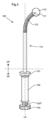
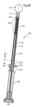
図3は、患者の逆流疾患を治療するための外科的処置で使用するための運動制限装置110を配置するための外科用器具100の第1の実施形態を示している。器具100は、外科手術中に患者の腹部に挿入されるように構成された遠位部分DPと、患者の体外に留まり、外科医によって取り扱われるように構成された近位部分PPから構成される。外科的処置。器具100は、スリーブ113を備え、その主要部分は遠位部分DPに配置される。スリーブ113は、第2のハンドリング部102に対して移動可能な第1のハンドリング部101に接続され、または一体化されている。図3に示される実施形態では、遠位部分の一部は可撓性であり、その結果、遠位部分は、器具100の主長軸LAに対して曲がることができ、したがって曲がることができる。図3に示すように、遠位部分DPの可撓性部分は、外科医が外科処置中に遠位部分を曲げることができるように動作可能に可撓性である。代替実施形態では、柔軟な部分は、柔軟な遠位部分の適切な角度ができるように、手動で、患者の外側および外科的処置の前にのみ曲げることができる。
FIG. 3 shows a first embodiment of a
図3に示す実施形態に戻ると、スリーブ113の遠位部は、可撓性スリーブ部112を含む。可撓性スリーブ部112は、例えば、螺旋状に巻かれた金属スリーブ、ポリマー材料から作られた可撓性スリーブ、織物可撓性金属スリーブ、または上記の組み合わせである。
Returning to the embodiment shown in FIG. 3, the distal portion of
器具100の遠位部DPは、外科処置中に運動制限装置110と係合し、したがって運動制限装置110を保持するように構成された保持装置111をさらに備える。保持装置111は、スリーブ113内に配置され、スリーブ113に対して変位可能であるように構成されている。図3に示すように、保持装置111は、運動制限装置110の凹部に係合し、それにより運動制限装置110を保持するように構成された突出部材を備える。運動制限装置は、第3操作部103に接続または一体化される。保持装置111は、第2のハンドリング部102に対して変位可能である(図4~6を参照してさらに詳しく説明する)。
Distal portion DP of
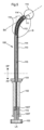
図4および図5は、第1の実施形態による外科用器具100を断面で示している。最も遠位の部分から開始するために、運動制限装置110は、運動制限装置110の凹部に係合する突出部材を有する保持装置111によって保持される。突出部材は、その最上部114 ’に固定または一体化される。細長い部材114は、外科医が外科手術中に遠位部分DPを曲げることができるように、動作可能に柔軟である。
Figures 4 and 5 show the
曲げ運動を生成する操作デバイスは、三角形の断面を有する複数の曲げ要素116を備え、曲げ要素116は、細長い部材114の左側で互いに接触し、右側の空隙によって分離されるようになっている。プルワイヤ115は、最上部の曲げ要素116の右側に固定され、最上部の曲げ要素に引張力を加えるように構成され、それにより、曲げ要素116の幾何学的形状は、細長い部材114を曲げさせ、曲げ要素116間の空隙が小さくなる。可撓性スリーブ部分112は、その中に配置された細長い部材114と共に曲がる。スリーブ113は、剛性部分および曲げるように構成された可撓性スリーブ部分112を備え、スリーブ113が細長い部材114および保持装置に対して変位可能であるため、曲げが始まる外科用器具上の点は、スリーブ113を移動させることにより移動し、器具を調整するためのさらなる手段を作り出す。
A manipulation device for generating a bending motion comprises a plurality of bending
細長い部材114の近位部分は、第2のハンドリング部102に接続または一体化され、したがって、細長い部材114の最上部114 ’および第2のハンドリング部102に接続された保持装置111である。ワイヤ115は、器具100の最遠位部分である第3のハンドリング部103に接続される。第3のハンドリング部103は、プルを操作するために、器具の主長軸LAの周りで第2のハンドリング部102に対して回転変位可能である。外科処置中に、ワイヤ115、したがって操作可能に柔軟な遠位部分。第3のハンドリング部103はねじ部103Tを備え、第2のハンドリング部102は対応するねじ部102Tを備え、第2のハンドリング部102に対する第3のハンドリング部103の回転変位は第3のハンドリング部103の直線変位を生じさせる。直線変位は、プルワイヤ115を近位方向に引っ張り、動作可能に柔軟な遠位部分を曲げさせる。
A proximal portion of the
図5は、第3のハンドリング部103が回転により操作され、プルワイヤ115が屈曲要素116が操作可能な可撓性の遠位部分をある角度まで曲げるのに十分な距離だけ引っ張られたときの外科用器具100の第1の実施形態を示す。器具の主長軸LAと屈曲軸BAとの間のα。これは、細長い部材の最上部114 ’および保持装置111の長軸である。一実施形態では、動作可能に柔軟な遠位部は屈曲するように構成される。 20°を超える角度αまで。一実施形態では、動作可能に柔軟な遠位部分は、30°を超える角度αに曲がるように構成される。一実施形態では、動作可能に柔軟な遠位部分は、45°を超える角度αに曲がるように構成される。一実施形態では、動作可能に柔軟な遠位部分は、60°を超える角度αに曲がるように構成される。一実施形態では、動作可能に柔軟な遠位部分は、75°を超える角度αに曲がるように構成される。一実施形態では、動作可能に柔軟な遠位部分は、90°を超える角度αに曲がるように構成される。
FIG. 5 illustrates the surgical procedure when the
別の実施形態では、第3のハンドリング部は、プルワイヤ115を直線的に引っ張る直線的に変位可能なハンドリング部である。そのような実施形態では、第3のハンドリング部は、第2のハンドリング部に摺動可能に接続され、そのような実施形態では、器具の主長軸LAに沿って近位方向に引っ張ることができ、操作可能な柔軟な遠位部分の曲げを作り出す。
In another embodiment, the third handling portion is a linearly displaceable handling portion that pulls the
ここで、保持装置111の動作に目を向ける。図6Aは、第1の実施形態による外科用器具100の直線構成を断面で示している。第1のハンドリング部101は、器具の主長軸LAに沿って第2のハンドリング部102に対して直線的に変位可能である。第1のハンドリング部101がスリーブ113と一体化されると、第1のハンドリング部101の遠位方向への直線変位により、スリーブ113の最遠位部分も遠位方向に移動し、したがって最上部を越えて通過する。スリーブ113と保持装置111のこの相対変位は、保持装置の突出部材が保持装置111から外れることにより、保持装置111を運動制限装置110から外す。したがって、手術器具100は、運動制限装置を患者の体内に配置し、その後、腹部から取り外すことができる。
We now turn to the operation of the retaining
図6Bは、第1のハンドリング部101が器具の主長軸LAの周りで第2のハンドリング部102に対して回転変位可能である外科用器具100の代替実施形態を示す。第1のハンドリング部101はねじ部101Tを備え、第2のハンドリング部102および/またはスリーブ113は対応するねじ部113Tを備え、第2のハンドリング部102に対する第1のハンドリング部101の回転変位は、器具の主長軸LAに沿った、第2のハンドリング部101に対する第1のハンドリング部101の角度に関連して、線形変位を生じさせる。
FIG. 6B shows an alternative embodiment of
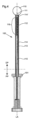
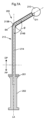
図7Aおよび図7Bは、外科用器具200の第2の実施形態を示す。第2の実施形態では、遠位部分DPは、固定曲げによって器具200の主長軸LAに対して曲げられる。図1に示す実施形態では、図7Aでは、主長軸LAは、保持装置211および運動制限装置210の曲げ軸BAに対して角度βで曲げられている。一実施形態では、屈曲部の角度βは20°を超える。一実施形態では、屈曲部の角度βは30°を超える。一実施形態では、屈曲部の角度βは45°を超える。一実施形態では、屈曲部の角度βは60°を超える。一実施形態では、屈曲部の角度βは75°を超える。一実施形態では、屈曲部の角度βは90°を超える。
7A and 7B show a second embodiment of
図1に示す実施形態では、図7Aでは、スリーブ213は剛性であり、剛性ベンド213Bを含むが、細長い部材214の遠位部分は可撓性であり、スリーブ213内に可撓性ベンド214Bを形成し、細長い部材214は、曲げが固定されていても、スリーブ213に対して変位できる。
In the embodiment shown in FIG. 1,
代替実施形態では、細長い部材214の遠位部分は剛性であり、剛性の曲げを含むが、スリーブ213の遠位部分は可撓性であり、可撓性の曲げを形成するため、これにより、曲げが固定されていても、細長い部材214をスリーブ213に対して変位させることができる。
In an alternative embodiment, the distal portion of
図7Bは、細長い部材214、したがって保持装置211がスリーブ213に対して変位し、運動制限装置210が器具から外された状態の外科用器具200の第2の実施形態を示す。
FIG. 7B shows a second embodiment of
第2の実施形態による器具は、スリーブ213が細長い部材214に対して直接直線的に変位可能であるように示されているが、第2の実施形態による器具が、図6に示すように、回転する第1のハンドリング部を備えることも同様に考えられる。
Although the device according to the second embodiment is shown such that the
図8A~8Dは、本明細書の実施形態の1つによる外科用器具300を使用して運動制限装置310を埋め込むことにより、患者の逆流疾患を治療する外科的方法を示す。
8A-8D illustrate a surgical method of treating reflux disease in a patient by implanting a
図8Aでは、運動制限装置310を保持する器具300は、患者の腹部に切開を施して患者の腹部に挿入されている。図8Aに示される手順ステップの前に、胃の基底部を含む領域で切開するステップが行われ、その結果、運動制限装置310は、患者の基底と係合して配置することができる。手術器具が動作して胃の外側に胃の基底部に接触する運動制限装置を配置する間、グラスパーは基底の胃壁を保持するために使用される。実施形態では、外科用器具が曲げられるとき、器具は、運動制限デバイスを位置決めするための曲げで器具を回転させるステップによって位置決めされ得る。外科用器具の遠位部分が動作可能に可撓性である実施形態では、動作制限デバイスを位置決めするために動作可能に可撓性の遠位部分を動作させるステップによって器具を位置決めすることができる。
In FIG. 8A, the
患者の逆流疾患を治療するための外科的処置で使用するための運動制限装置を配置するための外科用器具の開示された要素は、患者の体内でインプラントまたは手術道具を保持および解放する必要がある場合、他の用途に使用することができる。一般的な器具は、スリーブ、医療用インプラントまたは外科用ツールと係合するように構成された保持装置を備えてもよく、保持装置は、スリーブ内に配置され、スリーブ、スリーブに接続された第1のハンドリング部、および保持装置に接続された第2のハンドリング部に対して変位可能であるように構成される。第1および第2のハンドリング部の少なくとも一方のハンドリングは、スリーブに対する保持装置の相対的変位を生じさせ、医療インプラントまたは外科ツールの配置を実行するために医療インプラントまたは外科ツールから保持装置を外す。 The disclosed elements of a surgical instrument for deploying a motion restriction device for use in a surgical procedure to treat reflux disease in a patient require holding and releasing an implant or surgical tool within the patient's body. In some cases, it can be used for other purposes. A typical instrument may include a sleeve, a retention device configured to engage a medical implant or surgical tool, the retention device disposed within the sleeve and connected to the sleeve, the sleeve, and a second device connected to the sleeve. It is configured to be displaceable with respect to one handling part and a second handling part connected to the holding device. Handling by at least one of the first and second handling portions causes relative displacement of the retaining device with respect to the sleeve to disengage the retaining device from the medical implant or surgical tool to effect placement of the medical implant or surgical tool.
図8A~図8Dに示される外科的処置では、運動制限装置は、外科縫合針による胃から胃への縫合糸301によって胃底壁に陥入される。しかしながら、胃壁に運動制限装置を陥入させるステップでステープル装置を使用することも同様に考えられる。
In the surgical procedure shown in FIGS. 8A-8D, the motion restriction device is invaginated into the fundic wall by gastric-to-
図8Bおよび図8Cは、運動制限装置310が胃壁の外側、その外側の作成されたポーチに固定的に配置されるように、運動制限装置310を陥入させるためのさらなる縫合を示す。
8B and 8C show additional sutures to invaginate the
図8Dは、保持装置311に対してスリーブ313を変位させることにより、運動制限装置を外す器具のステップを示している。図8A~図8Dでは、保持装置311は突出部材を備え、運動制限装置310は突出部材と係合するように構成された凹部を備え、保持装置に対してスリーブ313を変位させることにより運動制限装置310を解放するステップを行う。 311は、突出部材を凹部から外すことを含む。その後、器具310が患者の腹部から除去される。
FIG. 8D shows the steps of the instrument removing the motion restriction device by displacing the
図8A~8Dに示される手順ステップは、腹腔鏡手術法のステップであり、この場合、外科的方法は、腹腔に液体または気体を充填するために腹壁を通してチューブを導入し、それによって腹腔を拡張して視覚空間を作り出すステップをさらに含む。この方法はさらに、2つ以上のトロカールを腹腔内に導入すること、およびトロカールの1つを通して腹腔内にカメラを導入することを含む。次に、この方法は、トロカールを介して腹腔内に手術器具を導入する前に、腹腔鏡切開器具を使用して腹部を切開することを含む。縫合またはステープラーによる固定は、腹腔鏡による縫合またはステープル留め器具を使用して行われ、この方法は、トロカールを通して腹腔内への外科用器具の取り外しによって終了する。 The procedural steps shown in FIGS. 8A-8D are laparoscopic surgical method steps, where the surgical method introduces a tube through the abdominal wall to fill the abdominal cavity with liquid or gas, thereby expanding the abdominal cavity. to create the visual space. The method further includes introducing two or more trocars into the abdominal cavity and introducing a camera into the abdominal cavity through one of the trocars. Next, the method includes using a laparoscopic incision to incise the abdomen prior to introducing surgical instruments into the abdominal cavity through the trocar. Suturing or stapling is performed using laparoscopic suturing or stapling instruments, the method terminating with removal of the surgical instruments through the trocar and into the abdominal cavity.
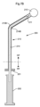
図9は、運動制限装置が基底壁に埋め込まれたときの食道と胃の上部を示す。運動制限装置は、複数の縫合糸305により胃12の壁に陥入することにより固定される。図1に示す実施形態では、図9に示されるように、運動制限装置の固定は、運動制限装置310の固定配置のための縫合糸305 ’による食道への胃底壁の固定が先行している。運動制限装置310は、好ましくは、少なくとも1つの層を備えることができる弾性の生体適合性シリコーン材料から作られる。例えば、金属層、パリレン層、ポリテトラフルオロエチレン層またはポリウレタン層である。
FIG. 9 shows the esophagus and upper part of the stomach when the motion restriction device is implanted in the basal wall. The motion restriction device is secured by invagination into the
運動制限装置は、40mm未満の最大直径、または30mm未満の最大直径、または20mm未満の最大直径を有してもよい。 The motion restriction device may have a maximum diameter of less than 40 mm, or a maximum diameter of less than 30 mm, or a maximum diameter of less than 20 mm.
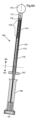
図10は、患者の逆流疾患を治療するための外科的処置で使用するための運動制限装置110の配置のための外科用器具100の第3の実施形態を示す。第3の実施形態に示される器具は、第1の実施形態に示される器具に類似しており、対応する要素には同様の番号が付けられている。器具100は、スリーブ113を備える。スリーブ113は、第1のハンドリング部101に接続または一体化される。第1のハンドリング101部は、近位部Pおよび遠位部Dを備える。第1のハンドリング部101は、好ましくは溝または凹部を備える。第2のハンドリング部102の部品を配置することができる。第2のハンドリング部102は、好ましくは、スリーブ113の内側の長手方向軸に沿って延びる細長い部材114と一体化される。第2のハンドリング部102は、保持できるように細長い部材の近位端のループを形成することによって形成され得る。その溝または凹部によって第1のハンドリング部101に配置される。細長い部材は、好ましくはワイヤであり得る。第1のハンドリング部101は、所定の変位量で第2のハンドリング部102の相対変位を停止するように適合された少なくとも1つの停止部104a、104bをさらに備えてもよい。
FIG. 10 shows a third embodiment of
器具100は、外科処置中に運動制限デバイス110と係合し、したがって運動制限デバイス110を保持するように構成された保持装置111をさらに備える。保持装置111は、スリーブ113内に配置され、スリーブ113に対して変位可能であるように構成される。保持装置111は、第1のハンドリング部101と第2のハンドリング部との間の相対変位が生じるように細長い部材114と一体化されてもよい。 102は、スリーブ113と保持装置111との間の相対的な変位をもたらす。図10に示すように、保持装置111は、運動制限装置110の凹部に係合し、それにより運動制限装置110を保持するように構成された突出部材を備える。
次に、保持装置111の動作に移る。図11Aおよび11Bは、第3の実施形態による外科用器具100を示す。図11Aでは、第2のハンドリング部102は、細長い部材114のループ状近位端として形成され、第1のハンドリング部の溝または凹部内に部分的に配置される。細長い部材114の近位端は、保持装置111で終わる。第2のハンドリング部102が第1のハンドリング部101の近位位置に配置されると、保持装置111は、保持部材111がスリーブ113から延びる。 111は、運動制限装置110と係合することができる。
Next, the operation of the holding
第1のハンドリング部101は、器具の主長軸に沿って第2のハンドリング部102に対して直線的に変位可能である。第1のハンドリング部101がスリーブ113と一体化されると、第1のハンドリング部101の遠位方向への直線変位により、スリーブ113の最遠位部分も遠位方向に移動し、したがって最上部を越えて通過する。スリーブ113と保持装置111のこの相対変位は、保持装置111の突出部材が凹部から外れることにより、保持装置111を運動制限装置110から外す。実際には、図11Bに示すように、この相対変位は、第2のハンドリング部102を第1のハンドリング部101の遠位位置から第1のハンドリング部の近位位置にハンドリングすることにより達成できる。これにより、スリーブ113と保持装置111との相対変位が達成され、保持装置111が運動制限装置110から外れる。したがって、手術器具100は、運動制限装置を患者の体内に配置し、その後、腹部から取り外すことができる。
The
図12Aおよび12Bは、側面図でトロカール112の内側に配置されたときの、第3の実施形態による外科用器具100を示す。 トロカール112は、運動制限装置110を胃壁に配置できるように、腹壁組織の拡張を支援する。 上述のように、外科用器具100が運動制限装置を体内に配置すると、外科用器具100をトロカール112から取り外し、続いてトロカール112を身体から取り外すことができる。
12A and 12B show
実施形態または実施形態の一部、ならびに方法または方法の一部または装置または装置の一部または機能または機能の一部またはシステムまたはシステムの一部は、適用可能な方法で組み合わせることができることに留意されたい。 本明細書のすべての例は、一般的な説明の一部とみなされるべきであり、したがって、一般的な用語で何らかの形で組み合わせることが可能である。 Note that embodiments or parts of embodiments and methods or parts of methods or devices or parts of devices or functions or parts of functions or systems or parts of systems may be combined in any applicable way. want to be All examples herein should be considered part of the general description and thus can be combined in some way in general terms.
Claims (22)
前記外科用器具(100)は、
-スリーブ(113)、
-前記スリーブ(113)内に配置され、該スリーブ(113)に対して変位可能に構成され、前記運動制限装置(110)と係合するように構成された保持装置(111)、
-前記スリーブ(113)に接続された第1のハンドリング部(101)、
-前記保持装置(111)に接続された第2のハンドリング部(102)、
とを備え、
前記第1および第2のハンドリング部(101,102)の少なくとも一方のハンドリング部は、前記スリーブ(113)に対する前記保持装置(111)の相対変位を生じさせるとともに、前記保持装置(111)を前記運動制限装置(10)から後退させて前記運動制限装置が前記スリーブ(113)に当接することにより生じるさらなる相対変位により、前記保持装置(111)の前記運動制限装置(10)との係合を外して当該運動制限装置(10)の腹部配置を実行する、外科用器具(100)であり、
前記保持装置(111)は、前記第2のハンドリング部(102)に接続された細長い部材(114)上に配置されているとともに一体化されており、さらに、
前記第2のハンドリング部(102)は、前記細長い部材(114)の近位端部から形成される、外科用器具(100)。 A surgical instrument (100) for abdominal placement of a motion restriction device (110) adapted to restrict movement of the cardiac sphincter (14) for use in a surgical procedure for treating reflux disease in a patient. ) and
The surgical instrument (100) comprises:
- a sleeve (113),
- a retaining device (111) arranged in said sleeve (113) and configured to be displaceable relative to said sleeve (113) and configured to engage said movement limiting device (110),
- a first handling part (101) connected to said sleeve (113),
- a second handling part (102) connected to said holding device (111),
and
At least one of the first and second handling parts (101, 102) causes a relative displacement of the holding device (111) with respect to the sleeve (113) and moves the holding device (111) to the Further relative displacement caused by withdrawal from the motion-limiting device (10) and said motion-limiting device abutting against said sleeve (113) disengages said retaining device (111) from engagement with said motion-limiting device (10). A surgical instrument (100) for removal to perform abdominal placement of the motion restriction device (10),
said holding device (111) is arranged on and integral with an elongated member (114) connected to said second handling portion (102);
Surgical instrument (100) wherein said second handling portion (102) is formed from a proximal end of said elongated member (114).
使用時に患者の身体に入るように構成された遠位部分(DP)と、使用時に患者の身体の外側に残るように構成された近位部分(PP)とを備え、
前記保持装置(111)は前記遠位部分(DP)に配置され、前記第1および第2のハンドリング部(101,102)は前記近位部分(PP)内に配置される、請求項1に記載の外科用器具(100)。 The surgical instrument (100) comprises:
a distal portion (DP) configured to enter a patient's body in use and a proximal portion (PP) configured to remain outside the patient's body in use;
2. The method of claim 1, wherein the holding device (111) is arranged in the distal part (DP) and the first and second handling parts (101, 102) are arranged in the proximal part (PP). A surgical instrument (100) as described.
前記第2のハンドリング部(102)および前記スリーブ(113)の少なくとも一方がねじ部(113T)を備え、
前記第2のハンドリング部(102)に対する前記第1のハンドリング部(101)の回転変位は、前記第2のハンドリング部(102)に対する前記第1のハンドリング部(101)の前記主長軸(LA)に沿った直線的な変位を生じさせる、請求項5に記載の外科用器具(100)。 said first handling part (101) comprises a threaded part (101T),
at least one of said second handling portion (102) and said sleeve (113) comprises a threaded portion (113T);
The rotational displacement of the first handling part (101) relative to the second handling part (102) is the major longitudinal axis (LA) of the first handling part (101) relative to the second handling part (102). 6. The surgical instrument (100) of claim 5 , wherein the linear displacement along the .
前記外科用器具(100)は、
-スリーブ(113)、
-前記スリーブ(113)内に配置され、該スリーブ(113)に対して変位可能に構成され、前記運動制限装置(110)と係合するように構成された保持装置(111)、
-前記スリーブ(113)に接続された第1のハンドリング部(101)、
-前記保持装置(111)に接続された第2のハンドリング部(102)、
とを備え、
前記第1および第2のハンドリング部(101,102)の少なくとも一方のハンドリング部は、前記スリーブ(113)に対する前記保持装置(111)の相対変位を生じさせるとともに、前記保持装置(111)を前記運動制限装置(10)から後退させて前記運動制限装置が前記スリーブ(113)に当接することにより生じるさらなる相対変位により、前記保持装置(111)の前記運動制限装置(10)との係合を外して当該運動制限装置(10)の腹部配置を実行する、外科用器具(100)であり、
前記外科用器具(100)は遠位部分(DP)を備え、
前記遠位部分(DP)は、前記外科用器具(100)の主長軸(LA)に対して屈曲可能であるように可撓性であり、
前記外科用器具(100)はさらに近位部分(PP)を備え、前記近位部分(PP)が、外科処置中に前記遠位部分(DP)を操作するための第3のハンドリング部(103)をさらに含む、外科用器具(100)。 A surgical instrument (100) for abdominal placement of a motion restriction device (110) adapted to restrict movement of the cardiac sphincter (14) for use in a surgical procedure for treating reflux disease in a patient. ) and
The surgical instrument (100) comprises:
- a sleeve (113),
- a retaining device (111) arranged in said sleeve (113) and configured to be displaceable relative to said sleeve (113) and configured to engage said movement limiting device (110),
- a first handling part (101) connected to said sleeve (113),
- a second handling part (102) connected to said holding device (111),
and
At least one of the first and second handling parts (101, 102) causes a relative displacement of the retaining device (111) with respect to the sleeve (113) and moves the retaining device (111) to the Further relative displacement caused by withdrawal from the motion-limiting device (10) and said motion-limiting device abutting against said sleeve (113) disengages said retaining device (111) from engagement with said motion-limiting device (10). A surgical instrument (100) for removal to perform abdominal placement of the motion restriction device (10),
The surgical instrument (100) comprises a distal portion (DP),
said distal portion (DP) is flexible so as to be bendable relative to a major longitudinal axis (LA) of said surgical instrument (100);
Said surgical instrument (100) further comprises a proximal portion (PP), said proximal portion (PP) having a third handling portion (103) for manipulating said distal portion (DP) during a surgical procedure. ), the surgical instrument (100) further comprising :
Priority Applications (1)
| Application Number | Priority Date | Filing Date | Title |
|---|---|---|---|
| JP2023136085A JP2023162312A (en) | 2017-08-16 | 2023-08-24 | Abdominal instrument and method |
Applications Claiming Priority (3)
| Application Number | Priority Date | Filing Date | Title |
|---|---|---|---|
| SE1750996-9 | 2017-08-16 | ||
| SE1750996A SE541401C2 (en) | 2017-08-16 | 2017-08-16 | Abdominal instrument |
| PCT/EP2018/072042 WO2019034661A1 (en) | 2017-08-16 | 2018-08-14 | Abdominal instrument and method |
Related Child Applications (1)
| Application Number | Title | Priority Date | Filing Date |
|---|---|---|---|
| JP2023136085A Division JP2023162312A (en) | 2017-08-16 | 2023-08-24 | Abdominal instrument and method |
Publications (4)
| Publication Number | Publication Date |
|---|---|
| JP2020531098A JP2020531098A (en) | 2020-11-05 |
| JP2020531098A5 JP2020531098A5 (en) | 2021-07-26 |
| JPWO2019034661A5 JPWO2019034661A5 (en) | 2022-10-24 |
| JP7339240B2 true JP7339240B2 (en) | 2023-09-05 |
Family
ID=63449428
Family Applications (2)
| Application Number | Title | Priority Date | Filing Date |
|---|---|---|---|
| JP2020508594A Active JP7339240B2 (en) | 2017-08-16 | 2018-08-14 | Abdominal apparatus and method |
| JP2023136085A Pending JP2023162312A (en) | 2017-08-16 | 2023-08-24 | Abdominal instrument and method |
Family Applications After (1)
| Application Number | Title | Priority Date | Filing Date |
|---|---|---|---|
| JP2023136085A Pending JP2023162312A (en) | 2017-08-16 | 2023-08-24 | Abdominal instrument and method |
Country Status (8)
| Country | Link |
|---|---|
| US (2) | US11596539B2 (en) |
| EP (1) | EP3668459A1 (en) |
| JP (2) | JP7339240B2 (en) |
| KR (1) | KR20200054965A (en) |
| CN (2) | CN116269552A (en) |
| AU (3) | AU2018319204B2 (en) |
| SE (1) | SE541401C2 (en) |
| WO (1) | WO2019034661A1 (en) |
Citations (4)
| Publication number | Priority date | Publication date | Assignee | Title |
|---|---|---|---|---|
| JP2006051349A (en) | 2004-07-30 | 2006-02-23 | Cordis Neurovascular Inc | Embolic coil distribution system with u-shaped filament release mechanism |
| JP2011251164A (en) | 2004-07-09 | 2011-12-15 | Gi Dynamics Inc | Method and device for placing gastrointestinal sleeve |
| JP2012516196A (en) | 2009-01-29 | 2012-07-19 | ミルックス・ホールディング・エスエイ | Obesity treatment |
| US20140058434A1 (en) | 2012-08-21 | 2014-02-27 | Donald K. Jones | Releasable device system |
Family Cites Families (21)
| Publication number | Priority date | Publication date | Assignee | Title |
|---|---|---|---|---|
| US7060077B2 (en) * | 1992-09-04 | 2006-06-13 | Boston Scientific Scimed, Inc. | Suturing instruments and methods of use |
| US6494888B1 (en) * | 1999-06-22 | 2002-12-17 | Ndo Surgical, Inc. | Tissue reconfiguration |
| US6540789B1 (en) * | 2000-06-15 | 2003-04-01 | Scimed Life Systems, Inc. | Method for treating morbid obesity |
| US7247160B2 (en) * | 2002-12-30 | 2007-07-24 | Calypso Medical Technologies, Inc. | Apparatuses and methods for percutaneously implanting objects in patients |
| US7255675B2 (en) * | 2004-03-23 | 2007-08-14 | Michael Gertner | Devices and methods to treat a patient |
| CN101083954A (en) * | 2004-03-23 | 2007-12-05 | 米尼穆斯外科系统公司 | Devices and methods to treat a patient |
| US20050251176A1 (en) * | 2004-05-07 | 2005-11-10 | Usgi Medical Inc. | System for treating gastroesophageal reflux disease |
| US8246533B2 (en) * | 2006-10-20 | 2012-08-21 | Ellipse Technologies, Inc. | Implant system with resonant-driven actuator |
| US9526649B2 (en) * | 2008-10-10 | 2016-12-27 | Peter Forsell | Method and instrument for treating obesity |
| EP2367503A1 (en) * | 2008-11-25 | 2011-09-28 | AttenueX Technologies, Inc. | Implant with high vapor pressure medium |
| WO2010087756A1 (en) * | 2009-01-29 | 2010-08-05 | Milux Holding S.A. | Stomach instrument and method |
| EP3957283B1 (en) * | 2009-01-29 | 2023-12-13 | Implantica Patent Ltd. | Obesity treatment |
| EP2391315A4 (en) * | 2009-01-29 | 2012-12-12 | Milux Holding Sa | An apparatus for treating gerd |
| US20120089236A1 (en) * | 2010-10-08 | 2012-04-12 | E2 Llc | Anti-Reflux Devices and Methods for Treating Gastro-Esophageal Reflux Disease (GERD) |
| US10420665B2 (en) * | 2010-06-13 | 2019-09-24 | W. L. Gore & Associates, Inc. | Intragastric device for treating obesity |
| US8628554B2 (en) * | 2010-06-13 | 2014-01-14 | Virender K. Sharma | Intragastric device for treating obesity |
| US20130226219A1 (en) * | 2011-01-21 | 2013-08-29 | Obalon Therapeutics, Inc. | Intragastric device |
| US9314362B2 (en) * | 2012-01-08 | 2016-04-19 | Vibrynt, Inc. | Methods, instruments and devices for extragastric reduction of stomach volume |
| WO2017201424A1 (en) * | 2016-05-19 | 2017-11-23 | Metamodix, Inc. | Pyloric anchor retrieval tools and methods |
| US10828064B2 (en) * | 2018-03-01 | 2020-11-10 | Torax Medical, Inc. | Laparoscopic sizing instrument |
| KR20230071156A (en) * | 2020-09-22 | 2023-05-23 | 보스톤 사이언티픽 리미티드 | Medical refractive device and method of using the same |
-
2017
- 2017-08-16 SE SE1750996A patent/SE541401C2/en unknown
-
2018
- 2018-08-14 CN CN202310294241.0A patent/CN116269552A/en active Pending
- 2018-08-14 CN CN201880052734.0A patent/CN110996859B/en active Active
- 2018-08-14 WO PCT/EP2018/072042 patent/WO2019034661A1/en unknown
- 2018-08-14 US US16/636,344 patent/US11596539B2/en active Active
- 2018-08-14 EP EP18762454.9A patent/EP3668459A1/en active Pending
- 2018-08-14 AU AU2018319204A patent/AU2018319204B2/en active Active
- 2018-08-14 JP JP2020508594A patent/JP7339240B2/en active Active
- 2018-08-14 KR KR1020207007197A patent/KR20200054965A/en active IP Right Grant
-
2021
- 2021-10-08 AU AU2021245239A patent/AU2021245239B2/en active Active
-
2023
- 2023-02-21 US US18/111,913 patent/US20230210680A1/en active Pending
- 2023-08-24 JP JP2023136085A patent/JP2023162312A/en active Pending
-
2024
- 2024-01-12 AU AU2024200234A patent/AU2024200234A1/en active Pending
Patent Citations (4)
| Publication number | Priority date | Publication date | Assignee | Title |
|---|---|---|---|---|
| JP2011251164A (en) | 2004-07-09 | 2011-12-15 | Gi Dynamics Inc | Method and device for placing gastrointestinal sleeve |
| JP2006051349A (en) | 2004-07-30 | 2006-02-23 | Cordis Neurovascular Inc | Embolic coil distribution system with u-shaped filament release mechanism |
| JP2012516196A (en) | 2009-01-29 | 2012-07-19 | ミルックス・ホールディング・エスエイ | Obesity treatment |
| US20140058434A1 (en) | 2012-08-21 | 2014-02-27 | Donald K. Jones | Releasable device system |
Also Published As
| Publication number | Publication date |
|---|---|
| AU2018319204A1 (en) | 2020-04-02 |
| US20200163786A1 (en) | 2020-05-28 |
| WO2019034661A1 (en) | 2019-02-21 |
| AU2018319204B2 (en) | 2021-07-08 |
| CN110996859B (en) | 2023-04-11 |
| AU2024200234A1 (en) | 2024-02-01 |
| US11596539B2 (en) | 2023-03-07 |
| AU2021245239B2 (en) | 2023-10-12 |
| AU2021245239A1 (en) | 2021-11-04 |
| SE541401C2 (en) | 2019-09-17 |
| KR20200054965A (en) | 2020-05-20 |
| EP3668459A1 (en) | 2020-06-24 |
| US20230210680A1 (en) | 2023-07-06 |
| JP2020531098A (en) | 2020-11-05 |
| JP2023162312A (en) | 2023-11-08 |
| CN116269552A (en) | 2023-06-23 |
| CN110996859A (en) | 2020-04-10 |
| SE1750996A1 (en) | 2019-02-17 |
Similar Documents
| Publication | Publication Date | Title |
|---|---|---|
| US8469972B2 (en) | Methods and devices for reducing gastric volume | |
| JP5367933B2 (en) | A device for making and holding tissue bags | |
| US7988617B2 (en) | Extragastric minimally invasive methods and devices to treat obesity | |
| US6926722B2 (en) | Devices and related methods for securing a tissue fold | |
| US20150127021A1 (en) | Devices for reconfiguring a portion of the gastrointestinal tract | |
| AU2001294651A1 (en) | Methods and devices for folding and securing tissue | |
| BR112020020005A2 (en) | SYSTEMS AND METHODS FOR ANCHORING AND RESTRICTING GASTROINTESTINAL PROSTHESES | |
| JP7339240B2 (en) | Abdominal apparatus and method | |
| AU2011265332A1 (en) | Devices and methods to treat a patient |
Legal Events
| Date | Code | Title | Description |
|---|---|---|---|
| A521 | Request for written amendment filed |
Free format text: JAPANESE INTERMEDIATE CODE: A523 Effective date: 20210514 |
|
| A621 | Written request for application examination |
Free format text: JAPANESE INTERMEDIATE CODE: A621 Effective date: 20210514 |
|
| A977 | Report on retrieval |
Free format text: JAPANESE INTERMEDIATE CODE: A971007 Effective date: 20220330 |
|
| A131 | Notification of reasons for refusal |
Free format text: JAPANESE INTERMEDIATE CODE: A131 Effective date: 20220419 |
|
| A601 | Written request for extension of time |
Free format text: JAPANESE INTERMEDIATE CODE: A601 Effective date: 20220719 |
|
| A601 | Written request for extension of time |
Free format text: JAPANESE INTERMEDIATE CODE: A601 Effective date: 20220920 |
|
| A524 | Written submission of copy of amendment under article 19 pct |
Free format text: JAPANESE INTERMEDIATE CODE: A524 Effective date: 20221014 |
|
| A521 | Request for written amendment filed |
Free format text: JAPANESE INTERMEDIATE CODE: A523 Effective date: 20221017 |
|
| A131 | Notification of reasons for refusal |
Free format text: JAPANESE INTERMEDIATE CODE: A131 Effective date: 20230110 |
|
| A521 | Request for written amendment filed |
Free format text: JAPANESE INTERMEDIATE CODE: A523 Effective date: 20230410 |
|
| TRDD | Decision of grant or rejection written | ||
| A01 | Written decision to grant a patent or to grant a registration (utility model) |
Free format text: JAPANESE INTERMEDIATE CODE: A01 Effective date: 20230725 |
|
| A61 | First payment of annual fees (during grant procedure) |
Free format text: JAPANESE INTERMEDIATE CODE: A61 Effective date: 20230824 |
|
| R150 | Certificate of patent or registration of utility model |
Ref document number: 7339240 Country of ref document: JP Free format text: JAPANESE INTERMEDIATE CODE: R150 |