JP7337407B2 - Battery modules and battery packs containing the same - Google Patents
Battery modules and battery packs containing the same Download PDFInfo
- Publication number
- JP7337407B2 JP7337407B2 JP2021544392A JP2021544392A JP7337407B2 JP 7337407 B2 JP7337407 B2 JP 7337407B2 JP 2021544392 A JP2021544392 A JP 2021544392A JP 2021544392 A JP2021544392 A JP 2021544392A JP 7337407 B2 JP7337407 B2 JP 7337407B2
- Authority
- JP
- Japan
- Prior art keywords
- battery
- module
- cell stack
- battery cell
- end plate
- Prior art date
- Legal status (The legal status is an assumption and is not a legal conclusion. Google has not performed a legal analysis and makes no representation as to the accuracy of the status listed.)
- Active
Links
Images


Classifications
-
- H—ELECTRICITY
- H01—ELECTRIC ELEMENTS
- H01M—PROCESSES OR MEANS, e.g. BATTERIES, FOR THE DIRECT CONVERSION OF CHEMICAL ENERGY INTO ELECTRICAL ENERGY
- H01M50/00—Constructional details or processes of manufacture of the non-active parts of electrochemical cells other than fuel cells, e.g. hybrid cells
- H01M50/20—Mountings; Secondary casings or frames; Racks, modules or packs; Suspension devices; Shock absorbers; Transport or carrying devices; Holders
-
- H—ELECTRICITY
- H01—ELECTRIC ELEMENTS
- H01M—PROCESSES OR MEANS, e.g. BATTERIES, FOR THE DIRECT CONVERSION OF CHEMICAL ENERGY INTO ELECTRICAL ENERGY
- H01M50/00—Constructional details or processes of manufacture of the non-active parts of electrochemical cells other than fuel cells, e.g. hybrid cells
- H01M50/50—Current conducting connections for cells or batteries
- H01M50/502—Interconnectors for connecting terminals of adjacent batteries; Interconnectors for connecting cells outside a battery casing
- H01M50/507—Interconnectors for connecting terminals of adjacent batteries; Interconnectors for connecting cells outside a battery casing comprising an arrangement of two or more busbars within a container structure, e.g. busbar modules
-
- H—ELECTRICITY
- H01—ELECTRIC ELEMENTS
- H01M—PROCESSES OR MEANS, e.g. BATTERIES, FOR THE DIRECT CONVERSION OF CHEMICAL ENERGY INTO ELECTRICAL ENERGY
- H01M50/00—Constructional details or processes of manufacture of the non-active parts of electrochemical cells other than fuel cells, e.g. hybrid cells
- H01M50/20—Mountings; Secondary casings or frames; Racks, modules or packs; Suspension devices; Shock absorbers; Transport or carrying devices; Holders
- H01M50/258—Modular batteries; Casings provided with means for assembling
-
- H—ELECTRICITY
- H01—ELECTRIC ELEMENTS
- H01M—PROCESSES OR MEANS, e.g. BATTERIES, FOR THE DIRECT CONVERSION OF CHEMICAL ENERGY INTO ELECTRICAL ENERGY
- H01M50/00—Constructional details or processes of manufacture of the non-active parts of electrochemical cells other than fuel cells, e.g. hybrid cells
- H01M50/20—Mountings; Secondary casings or frames; Racks, modules or packs; Suspension devices; Shock absorbers; Transport or carrying devices; Holders
- H01M50/204—Racks, modules or packs for multiple batteries or multiple cells
- H01M50/207—Racks, modules or packs for multiple batteries or multiple cells characterised by their shape
- H01M50/211—Racks, modules or packs for multiple batteries or multiple cells characterised by their shape adapted for pouch cells
-
- H—ELECTRICITY
- H01—ELECTRIC ELEMENTS
- H01M—PROCESSES OR MEANS, e.g. BATTERIES, FOR THE DIRECT CONVERSION OF CHEMICAL ENERGY INTO ELECTRICAL ENERGY
- H01M50/00—Constructional details or processes of manufacture of the non-active parts of electrochemical cells other than fuel cells, e.g. hybrid cells
- H01M50/20—Mountings; Secondary casings or frames; Racks, modules or packs; Suspension devices; Shock absorbers; Transport or carrying devices; Holders
- H01M50/218—Mountings; Secondary casings or frames; Racks, modules or packs; Suspension devices; Shock absorbers; Transport or carrying devices; Holders characterised by the material
- H01M50/22—Mountings; Secondary casings or frames; Racks, modules or packs; Suspension devices; Shock absorbers; Transport or carrying devices; Holders characterised by the material of the casings or racks
- H01M50/222—Inorganic material
- H01M50/224—Metals
-
- H—ELECTRICITY
- H01—ELECTRIC ELEMENTS
- H01M—PROCESSES OR MEANS, e.g. BATTERIES, FOR THE DIRECT CONVERSION OF CHEMICAL ENERGY INTO ELECTRICAL ENERGY
- H01M50/00—Constructional details or processes of manufacture of the non-active parts of electrochemical cells other than fuel cells, e.g. hybrid cells
- H01M50/20—Mountings; Secondary casings or frames; Racks, modules or packs; Suspension devices; Shock absorbers; Transport or carrying devices; Holders
- H01M50/233—Mountings; Secondary casings or frames; Racks, modules or packs; Suspension devices; Shock absorbers; Transport or carrying devices; Holders characterised by physical properties of casings or racks, e.g. dimensions
- H01M50/24—Mountings; Secondary casings or frames; Racks, modules or packs; Suspension devices; Shock absorbers; Transport or carrying devices; Holders characterised by physical properties of casings or racks, e.g. dimensions adapted for protecting batteries from their environment, e.g. from corrosion
-
- H—ELECTRICITY
- H01—ELECTRIC ELEMENTS
- H01M—PROCESSES OR MEANS, e.g. BATTERIES, FOR THE DIRECT CONVERSION OF CHEMICAL ENERGY INTO ELECTRICAL ENERGY
- H01M50/00—Constructional details or processes of manufacture of the non-active parts of electrochemical cells other than fuel cells, e.g. hybrid cells
- H01M50/20—Mountings; Secondary casings or frames; Racks, modules or packs; Suspension devices; Shock absorbers; Transport or carrying devices; Holders
- H01M50/233—Mountings; Secondary casings or frames; Racks, modules or packs; Suspension devices; Shock absorbers; Transport or carrying devices; Holders characterised by physical properties of casings or racks, e.g. dimensions
- H01M50/242—Mountings; Secondary casings or frames; Racks, modules or packs; Suspension devices; Shock absorbers; Transport or carrying devices; Holders characterised by physical properties of casings or racks, e.g. dimensions adapted for protecting batteries against vibrations, collision impact or swelling
-
- H—ELECTRICITY
- H01—ELECTRIC ELEMENTS
- H01M—PROCESSES OR MEANS, e.g. BATTERIES, FOR THE DIRECT CONVERSION OF CHEMICAL ENERGY INTO ELECTRICAL ENERGY
- H01M50/00—Constructional details or processes of manufacture of the non-active parts of electrochemical cells other than fuel cells, e.g. hybrid cells
- H01M50/20—Mountings; Secondary casings or frames; Racks, modules or packs; Suspension devices; Shock absorbers; Transport or carrying devices; Holders
- H01M50/244—Secondary casings; Racks; Suspension devices; Carrying devices; Holders characterised by their mounting method
-
- H—ELECTRICITY
- H01—ELECTRIC ELEMENTS
- H01M—PROCESSES OR MEANS, e.g. BATTERIES, FOR THE DIRECT CONVERSION OF CHEMICAL ENERGY INTO ELECTRICAL ENERGY
- H01M50/00—Constructional details or processes of manufacture of the non-active parts of electrochemical cells other than fuel cells, e.g. hybrid cells
- H01M50/20—Mountings; Secondary casings or frames; Racks, modules or packs; Suspension devices; Shock absorbers; Transport or carrying devices; Holders
- H01M50/262—Mountings; Secondary casings or frames; Racks, modules or packs; Suspension devices; Shock absorbers; Transport or carrying devices; Holders with fastening means, e.g. locks
- H01M50/264—Mountings; Secondary casings or frames; Racks, modules or packs; Suspension devices; Shock absorbers; Transport or carrying devices; Holders with fastening means, e.g. locks for cells or batteries, e.g. straps, tie rods or peripheral frames
-
- H—ELECTRICITY
- H01—ELECTRIC ELEMENTS
- H01M—PROCESSES OR MEANS, e.g. BATTERIES, FOR THE DIRECT CONVERSION OF CHEMICAL ENERGY INTO ELECTRICAL ENERGY
- H01M50/00—Constructional details or processes of manufacture of the non-active parts of electrochemical cells other than fuel cells, e.g. hybrid cells
- H01M50/20—Mountings; Secondary casings or frames; Racks, modules or packs; Suspension devices; Shock absorbers; Transport or carrying devices; Holders
- H01M50/271—Lids or covers for the racks or secondary casings
-
- H—ELECTRICITY
- H01—ELECTRIC ELEMENTS
- H01M—PROCESSES OR MEANS, e.g. BATTERIES, FOR THE DIRECT CONVERSION OF CHEMICAL ENERGY INTO ELECTRICAL ENERGY
- H01M50/00—Constructional details or processes of manufacture of the non-active parts of electrochemical cells other than fuel cells, e.g. hybrid cells
- H01M50/50—Current conducting connections for cells or batteries
- H01M50/502—Interconnectors for connecting terminals of adjacent batteries; Interconnectors for connecting cells outside a battery casing
- H01M50/505—Interconnectors for connecting terminals of adjacent batteries; Interconnectors for connecting cells outside a battery casing comprising a single busbar
-
- Y—GENERAL TAGGING OF NEW TECHNOLOGICAL DEVELOPMENTS; GENERAL TAGGING OF CROSS-SECTIONAL TECHNOLOGIES SPANNING OVER SEVERAL SECTIONS OF THE IPC; TECHNICAL SUBJECTS COVERED BY FORMER USPC CROSS-REFERENCE ART COLLECTIONS [XRACs] AND DIGESTS
- Y02—TECHNOLOGIES OR APPLICATIONS FOR MITIGATION OR ADAPTATION AGAINST CLIMATE CHANGE
- Y02E—REDUCTION OF GREENHOUSE GAS [GHG] EMISSIONS, RELATED TO ENERGY GENERATION, TRANSMISSION OR DISTRIBUTION
- Y02E60/00—Enabling technologies; Technologies with a potential or indirect contribution to GHG emissions mitigation
- Y02E60/10—Energy storage using batteries
Description
(関連出願との相互参照)
本出願は、2019年10月24日付の韓国特許出願第10-2019-0133054号および2020年7月6日付の韓国特許出願第10-2020-0082995号に基づく優先権の利益を主張し、当該韓国特許出願の文献に開示されたすべての内容は本明細書の一部として含まれる。
(Cross-reference with related application)
This application claims the benefit of priority based on Korean Patent Application No. 10-2019-0133054 dated October 24, 2019 and Korean Patent Application No. 10-2020-0082995 dated July 6, 2020, All contents disclosed in the documents of the Korean patent application are included as part of the present specification.
本発明は、電池モジュールおよびこれを含む電池パックに関し、より具体的には、電池セルのスウェリング防止のための新規な構造を有する電池モジュールおよび電池パックに関する。 TECHNICAL FIELD The present invention relates to a battery module and a battery pack including the same, and more specifically to a battery module and a battery pack having a novel structure for preventing swelling of battery cells.
製品群による適用の容易性が高く、高いエネルギー密度などの電気的特性を有する二次電池は、携帯用機器だけでなく、電気的駆動源によって駆動する電気自動車またはハイブリッド自動車、電力貯蔵装置などに普遍的に応用されている。このような二次電池は、化石燃料の使用を画期的に減少させることができるという一次的な利点だけでなく、エネルギーの使用による副産物が全く発生しないという点から、環境配慮型であり、且つエネルギー効率性アップのための新たなエネルギー源として注目されている。 Rechargeable batteries, which are easy to apply depending on the product group and have electrical characteristics such as high energy density, are not only used in portable devices, but also in electric vehicles or hybrid vehicles driven by an electric drive source, power storage devices, etc. universally applied. Such a secondary battery not only has the primary advantage of being able to dramatically reduce the use of fossil fuels, but also is environmentally friendly in that it does not generate any by-products from the use of energy. And it is attracting attention as a new energy source for improving energy efficiency.
小型モバイル機器にはデバイス1台あたり1個または2、3個の電池セルが用いられるのに対し、自動車などのような中大型デバイスには高出力大容量が必要である。したがって、多数の電池セルを電気的に連結した中大型電池モジュールが用いられる。 Small mobile devices use one, two or three battery cells per device, while medium and large devices such as automobiles require high output and large capacity. Therefore, medium and large battery modules in which a large number of battery cells are electrically connected are used.
中大型電池モジュールはできる限り小型で且つ軽量に製造されることが好ましいので、高い集積度で積層可能であり、容量対比重量が小さい角型電池、パウチ型電池などが中大型電池モジュールの電池セルとして主に用いられている。一方、電池モジュールは、電池セル積層体を外部からの衝撃、熱または振動から保護するために、前面と後面が開放されて電池セル積層体を内部空間に収納するフレーム部材を含むことができる。 Since it is preferable that medium- and large-sized battery modules are manufactured to be as small and lightweight as possible, battery cells for medium- and large-sized battery modules such as prismatic batteries and pouch-shaped batteries, which are small in weight relative to capacity, can be stacked with a high degree of integration. It is mainly used as Meanwhile, the battery module may include a frame member having an open front surface and a rear surface to house the battery cell stack in an internal space in order to protect the battery cell stack from external impact, heat, or vibration.
図1は、従来のモジュールフレームを有する電池モジュールを示す斜視図である。 FIG. 1 is a perspective view showing a battery module having a conventional module frame.
図1を参照すれば、電池モジュールは、複数の電池セル11が積層されて形成された電池セル積層体12と、電池セル積層体12を覆うように前面と後面が開放されたモノフレーム20と、モノフレーム20の前面および後面を覆うエンドプレート60とを含むことができる。このような電池モジュールを形成するために、図1に示した矢印のようにX軸方向に沿ってモノフレーム20の開放された前面または後面に電池セル積層体12が挿入されるように水平方向の組立が必要である。ただし、このような水平方向の組立が安定的になるように電池セル積層体12とモノフレーム20との間に十分な余裕空間(clearance)を確保しなければならない。ここで、余裕空間(clearance)とは、嵌め合いなどによって発生する隙間をいう。余裕空間が小さい場合に、水平方向の組立過程で部品の損傷が起こることがある。したがって、モノフレーム20の高さは、電池セル積層体12の最大高さと挿入過程での組立公差(tolerance)などを考慮して大きく設計されなければならない。したがって、それによって無駄な空間が発生することがある。
Referring to FIG. 1, the battery module includes a battery cell stack 12 formed by stacking a plurality of
これだけでなく、電池セルのスウェリングを制御するためにフレーム部材の厚さが厚くなる必要があり、空間活用性に劣る問題がある。 In addition, the thickness of the frame member must be increased in order to control the swelling of the battery cells, resulting in poor space utilization.
本発明が解決しようとする課題は、電池セルのスウェリング防止のための新規な構造を有する電池モジュールおよび電池パックを提供することである。 The problem to be solved by the present invention is to provide a battery module and battery pack having a novel structure for preventing swelling of battery cells.
しかし、本発明の実施例が解決しようとする課題は上述した課題に限定されず、本発明に含まれている技術的な思想の範囲で多様に拡張可能である。 However, the problems to be solved by the embodiments of the present invention are not limited to the problems described above, and can be variously expanded within the scope of the technical ideas included in the present invention.
本発明の一実施例による電池モジュールは、複数の電池セルが積層されている電池セル積層体と、前記電池セル積層体を収容すると共に上部が開放されたモジュールフレームと、前記モジュールフレームの上部において前記電池セル積層体を覆う上部プレートと、前記電池セル積層体と連結されるバスバーフレームと、前記電池セル積層体の両側に位置するエンドプレートとを含み、前記モジュールフレームは、前記電池セル積層体に含まれている前記電池セルの積層方向に沿って前記電池セル積層体を開放する構造を有し、前記モジュールフレームの開放された両側において前記エンドプレートが前記電池セル積層体の積層面を覆っている。 A battery module according to an embodiment of the present invention includes a battery cell stack in which a plurality of battery cells are stacked, a module frame that accommodates the battery cell stack and has an open top, and an upper portion of the module frame. The module frame includes an upper plate covering the battery cell stack, a busbar frame connected to the battery cell stack, and end plates positioned on both sides of the battery cell stack. The battery cell stack is opened along the stacking direction of the battery cells included in the module frame, and the end plates cover the stacking surfaces of the battery cell stack on both sides of the module frame where the module frame is opened. ing.
前記モジュールフレームは、底部および互いに対向する2つの側面部を含み、前記側面部と前記電池セル積層体との間に前記バスバーフレームが位置することができる。 The module frame may include a bottom portion and two side portions facing each other, and the busbar frame may be positioned between the side portions and the battery cell stack.
前記エンドプレートは、前記電池セルの電極リードが突出した方向に垂直な方向に位置することができる。 The end plates may be positioned in a direction perpendicular to a direction in which the electrode leads of the battery cells protrude.
前記電池モジュールは、前記バスバーフレームと前記モジュールフレームの前記側面部との間に位置する絶縁プレートをさらに含むことができる。 The battery module may further include an insulating plate positioned between the busbar frame and the side portion of the module frame.
前記上部プレートの両側には、下部に突出した第1係止部が形成される。 Both sides of the upper plate are formed with first locking portions that protrude downward.
前記エンドプレートは、上端部に第1段差部が形成され、前記第1段差部に前記第1係止部が係止可能である。 The end plate has a first stepped portion formed at an upper end thereof, and the first engaging portion can be engaged with the first stepped portion.
前記モジュールフレームの両側の底部には、上部に突出した第2係止部が形成される。 A second locking part protruding upward is formed at the bottom of both sides of the module frame.
前記エンドプレートの下端部に第2段差部が形成され、前記第2段差部に前記第2係止部が係止可能である。 A second stepped portion is formed at the lower end of the end plate, and the second locking portion can be locked to the second stepped portion.
前記第1段差部および前記第2段差部は、前記エンドプレートの前記上端部および下端部それぞれに溝構造(Groove)を形成することができる。 The first stepped portion and the second stepped portion may form grooves on the upper end portion and the lower end portion of the end plate, respectively.
前記エンドプレートは、前記第1段差部の両方の外縁に形成されたモジュールマウンティング部を有することができる。 The end plate may have module mounting portions formed on both outer edges of the first stepped portion.
前記モジュールマウンティング部に対応するように前記上部プレートには第1切開部が形成され、前記第1切開部によって前記モジュールマウンティング部の上端部が開放される。 A first cutout is formed in the upper plate so as to correspond to the module mounting part, and the first cutout opens an upper end of the module mounting part.
前記モジュールマウンティング部に対応するように前記モジュールフレームの底部には第2切開部が形成され、前記第2切開部によって前記モジュールマウンティング部の下端部が開放される。 A second cutout is formed in the bottom of the module frame to correspond to the module mounting part, and the second cutout opens the lower end of the module mounting part.
前記電池モジュールは、前記エンドプレートと前記電池セル積層体との間に位置する圧縮パッドをさらに含むことができる。 The battery module may further include a compression pad positioned between the end plate and the battery cell stack.
前記電池モジュールは、前記エンドプレートと前記電池セル積層体との間に位置する絶縁カバーをさらに含むことができる。 The battery module may further include an insulating cover positioned between the end plate and the battery cell stack.
前記絶縁カバーのZ軸方向への幅は、前記エンドプレートのZ軸方向への幅より大きく、前記絶縁カバーのZ軸方向への上端部と前記エンドプレートの上端部との間には第1段差部が形成され、前記第1段差部に前記第1係止部が係止可能である。 The width of the insulating cover in the Z-axis direction is larger than the width of the end plate in the Z-axis direction, and a first gap is provided between the upper end of the insulating cover in the Z-axis direction and the upper end of the end plate. A stepped portion is formed, and the first locking portion can be locked to the first stepped portion.
前記モジュールフレームの両側の底部には、上部に突出した第2係止部が形成される。 A second locking part protruding upward is formed at the bottom of both sides of the module frame.
前記絶縁カバーのZ軸方向への下端部と前記エンドプレートの下端部に第2段差部が形成され、前記第2段差部に前記第2係止部が係止可能である。 A second stepped portion is formed at the lower end of the insulating cover in the Z-axis direction and the lower end of the end plate, and the second locking portion can be locked to the second stepped portion.
前記エンドプレートは、金属物質で形成される。 The end plate is made of a metal material.
本発明の他の実施例による電池パックは、前述した電池モジュールを含む。 A battery pack according to another embodiment of the present invention includes the battery module described above.
実施例によれば、新規な構造の電池モジュールを実現して電池セルのスウェリングを効果的に制御しながら、空間活用率を高めることができる。 According to the embodiments, it is possible to realize a battery module with a novel structure, effectively control swelling of battery cells, and improve space utilization.
以下、添付した図面を参照して、本発明の様々な実施例について、本発明の属する技術分野における通常の知識を有する者が容易に実施できるように詳しく説明する。本発明は種々の異なる形態で実現可能であり、ここで説明する実施例に限定されない。 Various embodiments of the present invention will now be described in detail with reference to the accompanying drawings so that those skilled in the art can easily carry them out. This invention may be embodied in many different forms and is not limited to the illustrative embodiments set forth herein.
本発明を明確に説明するために説明上不必要な部分は省略し、明細書全体にわたって同一または類似の構成要素については同一の参照符号を付す。 In order to clearly explain the present invention, parts that are not necessary for explanation are omitted, and the same or similar components are given the same reference numerals throughout the specification.
また、図面に示された各構成の大きさおよび厚さは説明の便宜のために任意に示したので、本発明が必ずしも図示のところに限定されない。図面において、様々な層および領域を明確に表現するために厚さを拡大して示した。そして、図面において、説明の便宜のために、一部の層および領域の厚さを誇張して示した。 In addition, the size and thickness of each component shown in the drawings are arbitrarily shown for convenience of explanation, and the present invention is not necessarily limited to those shown in the drawings. In the drawings, the thicknesses are exaggerated for clarity of the various layers and regions. Also, in the drawings, the thickness of some layers and regions are exaggerated for convenience of explanation.
また、層、膜、領域、板などの部分が他の部分の「上に」あるとする時、これは、他の部分の「直上に」ある場合のみならず、その中間にさらに他の部分がある場合も含む。逆に、ある部分が他の部分の「直上に」あるとする時には、中間に他の部分がないことを意味する。さらに、基準となる部分の「上に」あるというのは、基準となる部分の上または下に位置するものであり、必ずしも重力の反対方向に向かって「上に」位置することを意味するわけではない。 Also, when a part such as a layer, film, region, plate, etc., is "on" another part, it means not only that it is "directly on" the other part, but also that there is another part in between. including when there is Conversely, when a part is said to be "directly on" another part, it means that there is no other part in between. Furthermore, being "above" a reference part means being above or below the reference part, not necessarily "above" in the direction opposite to the direction of gravity. isn't it.
また、明細書全体において、ある部分がある構成要素を「含む」とする時、これは、特に反対の記載がない限り、他の構成要素を除くのではなく、他の構成要素をさらに包含できることを意味する。 Also, throughout the specification, when a part "includes" a certain component, this does not mean that the other component is excluded, but that the other component can be further included unless specifically stated to the contrary. means
さらに、明細書全体において、「平面上」とする時、これは、対象部分を上からみた時を意味し、「断面上」とする時、これは、対象部分を垂直に切断した断面を横からみた時を意味する。 Furthermore, throughout the specification, the term “on a plane” means when the target portion is viewed from above, and the term “on a cross section” means a cross section obtained by cutting the target portion vertically. It means the time when viewed from the side.
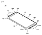
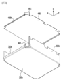
図2は、本発明の一実施例による電池モジュールを示す分解斜視図である。図3は、図2の電池モジュールの構成要素が結合した状態を示す斜視図である。図4は、図2の電池セル積層体に含まれている1つの電池セルを示す斜視図である。図5は、図3の電池モジュールにおけるモジュールフレーム、上部プレートおよびエンドプレートを上部から斜めに眺めた分解斜視図である。図6は、図3の電池モジュールにおけるモジュールフレームと上部プレートを下部から斜めに眺めた分解斜視図である。 FIG. 2 is an exploded perspective view showing a battery module according to one embodiment of the present invention. FIG. 3 is a perspective view showing a state in which components of the battery module of FIG. 2 are combined. 4 is a perspective view showing one battery cell included in the battery cell stack of FIG. 2. FIG. FIG. 5 is an exploded perspective view of the module frame, upper plate and end plates of the battery module of FIG. 3 obliquely viewed from above. FIG. 6 is an exploded perspective view of the module frame and upper plate in the battery module of FIG. 3 obliquely viewed from below.
図2および図3を参照すれば、本実施例による電池モジュール100は、複数の電池セル110が積層されて形成された電池セル積層体120と、電池セル積層体120が収納されるモジュールフレーム300と、モジュールフレーム300の開放された上部を覆う上部プレート400と、モジュールフレーム300の前面および後面を覆うエンドプレート150とを含むことができる。エンドプレート150は、アルミニウムのような金属物質で形成される。エンドプレート150は、モジュールフレーム300の一側を覆う前面プレートと、モジュールフレーム300の他の一側を覆う後面プレートとを含むことができる。
2 and 3, the
モジュールフレーム300は、U字状フレームであってもよく、前記U字状フレームの開放された両側をそれぞれ第1側と第2側とする時、モジュールフレーム300は、前記第1側および前記第2側に対応する電池セル積層体120の面を除いた残りの外面のうち、互いに隣接した前面、下面および後面を連続して囲むように折曲げられた板状構造からなる。モジュールフレーム300の下面に対応する上面は開放されている。本実施例において、モジュールフレーム300は、電池セル積層体120に含まれている電池セル110の積層方向に沿って電池セル積層体120を開放する構造を有する。この時、モジュールフレーム300の開放された両側においてエンドプレート150が電池セル積層体120の積層面を覆っている構造である。
The
本実施例による電池モジュール100は、モジュールフレーム300の側面部と電池セル積層体120との間に位置するバスバーフレーム130をさらに含み、バスバーフレーム130とモジュールフレーム300の側面部との間に位置する絶縁プレート135をさらに含むことができる。絶縁プレート135は、電極リード111、112およびバスバー131がモジュールフレーム300と絶縁できるようにする機能を有する。絶縁プレート135は、プラスチック射出物で形成される。
The
図2、図5および図6を参照すれば、本実施例によるモジュールフレーム300は、底部300aおよび互いに対向する2つの側面部300bを含む。また、本実施例による電池モジュール100は、電池セル積層体120がモジュールフレーム300の底部300aに装着される前に、モジュールフレーム300の底部300aに熱伝導性樹脂を塗布し、熱伝導性樹脂を硬化して形成された熱伝導性樹脂層310をさらに含む。
2, 5 and 6, the
本実施例による上部プレート400は、その両側から下部に突出した第1係止部400hを含む。第1係止部400hが形成された上部プレート400の両側は、電池セル積層体120が積層される方向であるX軸方向への両側に対応する。本実施例によるモジュールフレーム300は、モジュールフレーム300の前記第1側および前記第2側にそれぞれ形成された第2係止部300cをさらに含む。第2係止部300cは、モジュールフレーム300の底部300aの一端から上部に突出した構造に形成される。モジュールフレーム300の前記第1側および前記第2側は、電池セル積層体120が積層される方向であるX軸方向への両側に対応する。
The
図6に示すように、本実施例による上部プレート400には第1切開部AP1が形成されている。第1切開部AP1は、第1係止部400hの両端部に隣接して形成され、上部プレート400の4つの角に形成される。本実施例によるモジュールフレーム300の底部300aには第2切開部AP2が形成されている。第2切開部AP2は、第2係止部300cの両端部に隣接して形成され、モジュールフレーム300の底部300aの4つの角に形成される。
As shown in FIG. 6, the
上部プレート400は、モジュールフレーム300によって囲まれる前面、下面および後面を除いた残りの上面を囲む1つの板状構造からなる。モジュールフレーム300と上部プレート400は、互いに対応する角部位が接触した状態で、溶接などによって結合されることによって電池セル積層体120を囲む構造を形成することができる。つまり、モジュールフレーム300と上部プレート400は、互いに対応する角部位に溶接などの結合方法で形成された結合部が形成される。
The
電池セル積層体120は、一方向に積層された複数の電池セル110を含み、複数の電池セル110は、図2に示すように、X軸方向に積層できる。電池セル110は、パウチ型電池セルであることが好ましい。例えば、図4を参照すれば、本実施例による電池セル110は、2つの電極リード111、112が互いに対向し、電池本体113の一端部114aと他の一端部114bからそれぞれ突出している構造を有する。電池セル110は、電池ケース114に電極組立体(図示せず)を収納した状態で、ケース114の両端部114a、114bとこれらを連結する両側面114cとを接着することによって製造できる。言い換えれば、本実施例による電池セル110は、計3箇所のシーリング部114sa、114sb、114scを有し、シーリング部114sa、114sb、114scは、熱融着などの方法でシーリングされる構造であり、残りの他の一側部は、連結部115からなってもよい。電池ケース114の両端部114a、114bの間を電池セル110の長手方向と定義し、電池ケース114の両端部114a、114bを連結する一側部114cと連結部115との間を電池セル110の幅方向と定義することができる。
The
連結部115は、電池セル110の一周縁に沿って長く延びている領域であり、連結部115の端部に電池セル110の突出部110pが形成される。突出部110pは、連結部115の両端部の少なくとも1つに形成され、連結部115が延びる方向に垂直な方向に突出できる。突出部110pは、電池ケース114の両端部114a、114bのシーリング部114sa、114sbのうちの1つと連結部115との間に位置することができる。
The connecting
電池ケース114は、一般に樹脂層/金属薄膜層/樹脂層のラミネート構造からなる。例えば、電池ケースの表面がO(oriented)-ナイロン層からなる場合には、中大型電池モジュールを形成するために多数の電池セルを積層する時、外部衝撃によって滑りやすい傾向がある。したがって、これを防止し電池セルの安定した積層構造を維持するために、電池ケースの表面に両面テープなどの粘着式接着剤または接着時に化学反応によって結合される化学接着剤などの接着部材を付着させて電池セル積層体120を形成することができる。本実施例において、電池セル積層体120は、X軸方向に積層され、Z軸方向にモジュールフレーム300の内部に収容され、熱伝導性樹脂層310によって熱伝達され、電池モジュールに隣接した冷却部材によって冷却が行われる。これに対する比較例として、電池セルがカートリッジ形態の部品に形成され、電池セル間の固定が電池モジュールフレームへの組立で行われる場合がある。このような比較例では、カートリッジ形態の部品の存在によって、冷却作用がほとんどないか、または電池セルの面方向に行われ、電池モジュールの高さ方向には冷却がうまくいかなくなる。
The
図2および図4を再び参照すれば、エンドプレート150は、電池セル110の電極リード111、112が突出した方向に垂直な方向に位置することができる。
2 and 4, the
以下、図7および図8を参照して、本実施例による電池モジュールにおける電池セルのスウェリングを防止する構造について詳しく説明する。 Hereinafter, a structure for preventing swelling of battery cells in the battery module according to the present embodiment will be described in detail with reference to FIGS. 7 and 8. FIG.
図7は、図3の電池モジュールにおける上部プレートとエンドプレートとの結合関係を示すための斜視図である。図8は、図3の電池モジュールにおけるモジュールフレームとエンドプレートとの結合関係を示すための斜視図である。 FIG. 7 is a perspective view showing a coupling relationship between a top plate and an end plate in the battery module of FIG. 3; 8 is a perspective view showing a coupling relationship between a module frame and an end plate in the battery module of FIG. 3. FIG.
図2、図3および図7を参照すれば、本実施例による電池モジュールに含まれているエンドプレート150の上端部に第1段差部160が形成される。第1段差部160は、エンドプレート150を加工成形する時に形成され、図7に示すように、第1段差部160が形成されたエンドプレート150の上端部は、Z軸方向に若干突出した構造を有する。この時、第1段差部160に上部プレート400の第1係止部400hが係止可能である。第1段差部160に第1係止部400hが係止された状態で、上部プレート400とエンドプレート150とが互いに溶接によって結合できる。
2, 3 and 7, a first stepped
本実施例によるエンドプレート150は、第1段差部160の両方の外縁に形成されたモジュールマウンティング部154をさらに含む。モジュールマウンティング部154は、本実施例による電池モジュールがパックフレーム(図示せず)と結合して電池パックを構成するために用いられる構造物であってもよい。仮に、モジュールマウンティング部154にマウンティング部材(図示せず)が挿入されて、パックフレーム(図示せず)と電池モジュールとが連結可能である。この時、図6で説明した上部プレート400の第1切開部AP1にモジュールマウンティング部154が対応し、第1切開部AP1によってモジュールマウンティング部154の上端部が開放される。
The
図2、図3および図8を参照すれば、エンドプレート150の下端部に第2段差部170が形成される。第2段差部170は、エンドプレート150を加工成形する時に形成され、図8に示すように、第2段差部170が形成されたエンドプレート150の下端部は、Z軸方向に若干突出した構造を有する。この時、第2段差部170にモジュールフレーム300の底部300aの第2係止部300cが係止可能である。第2段差部170に第2係止部300cが係止された状態で、モジュールフレーム300の底部300aとエンドプレート150とが互いに溶接によって結合できる。
2, 3 and 8, a second stepped
図6で説明したモジュールフレーム300の底部300aの第2切開部AP2にモジュールマウンティング部154が対応し、第2切開部AP2によってモジュールマウンティング部154の下端部が開放される。
The module mounting portion 154 corresponds to the second cutout AP2 of the
以上に説明した本実施例による電池モジュール構造によれば、既存のU字状フレームモジュール構造においてモジュールフレームの位置を90度回転させることによって、電池セルのスウェリングが起こるX軸方向に沿ってエンドプレート150が形成される。したがって、エンドプレート150が電池セルのスウェリングを直接制御できるようにする。係止部400h、300cと段差部160、170の構造によって、エンドプレート150と上部プレート400およびエンドプレート150とモジュールフレーム300が固定され、固定される方向が電池セルのスウェリングが発生するX軸方向と一致するので、電池セルのスウェリングによる問題を効果的に制御することができる。それだけでなく、電池セルのスウェリング制御のためにエンドプレート150の厚さとモジュールフレームの底面の厚さを増加させる必要が無くなるので、空間活用率を増加させることができる。
According to the battery module structure according to the present embodiment described above, by rotating the position of the module frame in the existing U-shaped frame module structure by 90 degrees, the swelling of the battery cells occurs along the X-axis direction. A
図7および図8で説明した第1段差部160および第2段差部170は、エンドプレート150の上端部および下端部それぞれに溝構造(Groove)を形成することができる。エンドプレート150の第1、第2段差部160、170に第1、第2係止部400h、300cが固定されるため、上部プレート400とモジュールフレーム300の底部300aがエンドプレート150の最外側の面より突出するのを防止することができる。また、第1、第2段差部160、170は、エンドプレート150が上部プレート400およびモジュールフレーム300の底部300aと組立時にガイドの役割を果たすことができる。
The first stepped
図2を再び参照すれば、本実施例による電池モジュール100は、エンドプレート150と電池セル積層体120との間に位置する圧縮パッド119をさらに含むことができる。圧縮パッド119は、ウレタンフォームのような弾性部材で形成され、電池セルのスウェリング問題を追加的に低減することができる。また、圧縮パッド119は、エンドプレート150と電池セル積層体120との間に絶縁を維持する。
Referring back to FIG. 2 , the
以下、図9~図11を参照して、本発明の変形実施例について説明する。 Modified embodiments of the present invention will be described below with reference to FIGS. 9 to 11. FIG.
図9は、本発明の他の実施例による電池モジュールを示す分解斜視図である。図10は、図9の電池モジュールにおける上部プレートとエンドプレートとの結合関係を示すための斜視図である。図11は、図9の電池モジュールにおけるモジュールフレームとエンドプレートとの結合関係を示すための斜視図である。 FIG. 9 is an exploded perspective view of a battery module according to another embodiment of the present invention. FIG. 10 is a perspective view showing the coupling relationship between the upper plate and the end plate in the battery module of FIG. 9. FIG. 11 is a perspective view showing the coupling relationship between the module frame and the end plate in the battery module of FIG. 9. FIG.
図9および図10を参照すれば、本実施例による電池モジュールは、エンドプレート150と電池セル積層体120との間に位置する絶縁カバー140をさらに含む。絶縁カバー140は、プラスチック射出物で形成される。図10に示すように、絶縁カバー140のZ軸方向への幅は、エンドプレート150のZ軸方向への幅より大きい。絶縁カバー140は、エンドプレート150の上端面より上に延びている。この時、絶縁カバー140のZ軸方向への上端部とエンドプレート150の上端部との間に第1段差部160が形成され、第1段差部160に上部プレート400の第1係止部400hが係止可能である。具体的には、エンドプレート150の内側に形成される絶縁カバー140がエンドプレート150の厚さだけ後退しており、Z軸方向にエンドプレート150の上端面から突出した絶縁カバー140の部分とエンドプレート150の上端面とによって段差が形成される。このような段差に第1係止部400hが係止された状態で、上部プレート400とエンドプレート150とが互いに溶接によって結合できる。
9 and 10, the battery module according to this embodiment further includes an insulating
図9および図11を参照すれば、絶縁カバー140は、エンドプレート150の下端面より下へ延びている。この時、絶縁カバー140のZ軸方向への下端部とエンドプレート150の下端部との間に第2段差部170が形成され、第2段差部170にモジュールフレーム300の底部300aの第2係止部300cが係止可能である。具体的には、エンドプレート150の内側に形成される絶縁カバー140がエンドプレート150の厚さだけ後退しており、Z軸方向にエンドプレート150の下端面から突出した絶縁カバー140の部分とエンドプレート150の下端面とによって段差が形成される。このような段差に第2係止部300cが係止された状態で、モジュールフレーム300の底部300aとエンドプレート150とが互いに溶接によって結合できる。
9 and 11, the insulating
一方、本発明の実施例による電池モジュールは、1つまたはそれ以上がパックケース内にパッケージングされて電池パックを形成することができる。 Meanwhile, one or more battery modules according to embodiments of the present invention may be packaged in a pack case to form a battery pack.
先に説明した電池モジュールおよびこれを含む電池パックは、多様なデバイスに適用可能である。このようなデバイスには、電気自転車、電気自動車、ハイブリッド自動車などの運送手段に適用可能であるが、本発明はこれに制限されず、電池モジュールおよびこれを含む電池パックを使用できる多様なデバイスに適用可能であり、これも本発明の権利範囲に属する。 The battery modules and battery packs including the same described above can be applied to various devices. Such devices can be applied to transportation means such as electric bicycles, electric vehicles, and hybrid vehicles, but the present invention is not limited thereto, and can be applied to various devices that can use battery modules and battery packs including the same. applicable and also within the scope of the present invention.
以上、本発明の好ましい実施例について詳しく説明したが、本発明の権利範囲はこれに限定されるものではなく、以下の特許請求の範囲で定義している本発明の基本概念を利用した当業者の様々な変形および改良形態も本発明の権利範囲に属するのである。 Although the preferred embodiments of the present invention have been described in detail above, the scope of the invention is not limited thereto, and any person skilled in the art who utilizes the basic concepts of the invention defined in the following claims should be able to Various modifications and improvements of are also within the scope of the present invention.
11:電池セル
12:電池セル積層体
60:エンドプレート
100:電池モジュール
110:電池セル
111:電極リード
112:電極リード
119:圧縮パッド
120:電池セル積層体
130:バスバーフレーム
131:バスバー
135:絶縁プレート
140:絶縁カバー
150:エンドプレート
154:モジュールマウンティング部
160:第1段差部
170:第2段差部
300:モジュールフレーム
300a:底部
300b:側面部
300c:第2係止部
400:上部プレート
400h:第1係止部
300c:第2係止部
11: Battery cell 12: Battery cell laminate 60: End plate 100: Battery module 110: Battery cell 111: Electrode lead 112: Electrode lead 119: Compression pad 120: Battery cell laminate 130: Busbar frame 131: Busbar 135: Insulation Plate 140: Insulating cover 150: End plate 154: Module mounting part 160: First stepped part 170: Second stepped part 300:
Claims (12)
前記電池セル積層体を収容すると共に上部が開放されたモジュールフレームと、
前記モジュールフレームの上部において前記電池セル積層体を覆う上部プレートと、
前記電池セル積層体と連結されるバスバーフレームと、
前記電池セル積層体の両側に位置するエンドプレートとを含み、
前記モジュールフレームは、前記電池セルの積層方向に沿って前記電池セル積層体を開放する構造を有し、
前記モジュールフレームの開放された両側において前記エンドプレートが前記電池セル積層体の積層面を覆っており、
前記上部プレートの両側には、下部に突出した第1係止部が形成されており、
前記エンドプレートは、上端部に第1段差部が形成され、前記第1段差部に前記第1係止部が係止されており、
前記モジュールフレームの両側の底部には、上部に突出した第2係止部が形成されており、
前記エンドプレートの下端部に第2段差部が形成され、前記第2段差部に前記第2係止部が係止されており、
前記エンドプレートと前記電池セル積層体との間に位置する絶縁カバーをさらに含み、
前記電池セルの前記積層方向に垂直な方向のZ軸方向において、前記絶縁カバーの幅は、前記エンドプレートの幅より大きく、前記絶縁カバーの前記Z軸方向への上端部と前記エンドプレートの前記Z軸方向への上端部との間に第1段差部が形成され、前記第1段差部に前記第1係止部が係止されている、電池モジュール。 a battery cell stack in which a plurality of battery cells are stacked;
a module frame housing the battery cell stack and having an open top;
a top plate covering the battery cell stack on top of the module frame;
a busbar frame connected to the battery cell stack;
and end plates located on both sides of the battery cell stack,
The module frame has a structure that opens the battery cell stack along the stacking direction of the battery cells,
The end plates cover the stacking surfaces of the battery cell stack on both open sides of the module frame,
Both sides of the upper plate are formed with first locking portions protruding downward,
The end plate has a first stepped portion formed at an upper end portion, and the first locking portion is locked to the first stepped portion,
Second locking portions protruding upward are formed on the bottoms of both sides of the module frame,
A second stepped portion is formed at the lower end of the end plate, and the second locking portion is locked to the second stepped portion,
further comprising an insulating cover positioned between the end plate and the battery cell stack;
In the Z-axis direction perpendicular to the stacking direction of the battery cells, the width of the insulating cover is larger than the width of the end plate, and the upper end portion of the insulating cover in the Z-axis direction and the end plate A battery module, wherein a first stepped portion is formed between an upper end portion in the Z-axis direction, and the first locking portion is locked to the first stepped portion.
前記側面部と前記電池セル積層体との間に前記バスバーフレームが位置する、請求項1に記載の電池モジュール。 the module frame includes a bottom portion and two side portions facing each other;
2. The battery module according to claim 1, wherein said busbar frame is positioned between said side portion and said battery cell stack.
Applications Claiming Priority (5)
| Application Number | Priority Date | Filing Date | Title |
|---|---|---|---|
| KR20190133054 | 2019-10-24 | ||
| KR10-2019-0133054 | 2019-10-24 | ||
| KR1020200082995A KR102477607B1 (en) | 2019-10-24 | 2020-07-06 | Battery module and battery pack including the same |
| KR10-2020-0082995 | 2020-07-06 | ||
| PCT/KR2020/009089 WO2021080124A1 (en) | 2019-10-24 | 2020-07-10 | Battery module and battery pack including same |
Publications (2)
| Publication Number | Publication Date |
|---|---|
| JP2022519234A JP2022519234A (en) | 2022-03-22 |
| JP7337407B2 true JP7337407B2 (en) | 2023-09-04 |
Family
ID=75620166
Family Applications (1)
| Application Number | Title | Priority Date | Filing Date |
|---|---|---|---|
| JP2021544392A Active JP7337407B2 (en) | 2019-10-24 | 2020-07-10 | Battery modules and battery packs containing the same |
Country Status (4)
| Country | Link |
|---|---|
| US (1) | US20220158290A1 (en) |
| EP (1) | EP3926736A4 (en) |
| JP (1) | JP7337407B2 (en) |
| WO (1) | WO2021080124A1 (en) |
Families Citing this family (2)
| Publication number | Priority date | Publication date | Assignee | Title |
|---|---|---|---|---|
| KR20220039301A (en) * | 2020-09-22 | 2022-03-29 | 주식회사 엘지에너지솔루션 | Battery module and battery pack including the same |
| EP4239766A1 (en) * | 2022-03-04 | 2023-09-06 | SK On Co., Ltd. | Battery pack |
Citations (2)
| Publication number | Priority date | Publication date | Assignee | Title |
|---|---|---|---|---|
| CN107706325A (en) | 2017-06-30 | 2018-02-16 | 多氟多(焦作)新能源科技有限公司 | Power module and vehicle |
| CN208955070U (en) | 2018-11-15 | 2019-06-07 | 宁德时代新能源科技股份有限公司 | Side plate and battery modules |
Family Cites Families (4)
| Publication number | Priority date | Publication date | Assignee | Title |
|---|---|---|---|---|
| KR101642325B1 (en) * | 2013-10-17 | 2016-07-25 | 주식회사 엘지화학 | Battery module and battery pack including the same |
| KR101688489B1 (en) * | 2013-11-19 | 2016-12-21 | 삼성에스디아이 주식회사 | Battery module |
| US10601003B2 (en) * | 2017-10-30 | 2020-03-24 | Lg Chem, Ltd. | Battery module and method of assembling the battery module |
| KR102159347B1 (en) * | 2017-11-14 | 2020-09-23 | 주식회사 엘지화학 | Battery module having end plates pressurizing battery cells and extensible sensing housing parts |
-
2020
- 2020-07-10 EP EP20878274.8A patent/EP3926736A4/en active Pending
- 2020-07-10 US US17/440,423 patent/US20220158290A1/en active Pending
- 2020-07-10 WO PCT/KR2020/009089 patent/WO2021080124A1/en active Application Filing
- 2020-07-10 JP JP2021544392A patent/JP7337407B2/en active Active
Patent Citations (2)
| Publication number | Priority date | Publication date | Assignee | Title |
|---|---|---|---|---|
| CN107706325A (en) | 2017-06-30 | 2018-02-16 | 多氟多(焦作)新能源科技有限公司 | Power module and vehicle |
| CN208955070U (en) | 2018-11-15 | 2019-06-07 | 宁德时代新能源科技股份有限公司 | Side plate and battery modules |
Also Published As
| Publication number | Publication date |
|---|---|
| EP3926736A1 (en) | 2021-12-22 |
| US20220158290A1 (en) | 2022-05-19 |
| EP3926736A4 (en) | 2022-05-11 |
| JP2022519234A (en) | 2022-03-22 |
| WO2021080124A1 (en) | 2021-04-29 |
Similar Documents
| Publication | Publication Date | Title |
|---|---|---|
| KR102473335B1 (en) | Battery module and battery pack including the same | |
| JP7282435B2 (en) | BATTERY MODULE, MANUFACTURING METHOD THEREOF, AND BATTERY PACK | |
| JP7297365B2 (en) | Battery modules and battery packs containing the same | |
| KR102477607B1 (en) | Battery module and battery pack including the same | |
| JP7210088B2 (en) | Battery module and battery pack containing same | |
| JP7451007B2 (en) | Battery module, its manufacturing method and battery pack | |
| KR102465865B1 (en) | Battery module, method of manufacturing the same and battery pack | |
| JP7354265B2 (en) | Battery module, its manufacturing method and battery pack | |
| JP7337407B2 (en) | Battery modules and battery packs containing the same | |
| US20230012792A1 (en) | Battery module and battery pack including the same | |
| JP7278392B2 (en) | Battery modules and battery packs containing the same | |
| US20240030512A1 (en) | Battery module and battery pack including the same | |
| JP2022523953A (en) | Battery module and battery pack containing it | |
| JP7297370B2 (en) | BATTERY MODULE, MANUFACTURING METHOD THEREOF, AND BATTERY PACK | |
| US20230282925A1 (en) | Battery module and battery pack including the same | |
| KR20220051776A (en) | Battery module and battery pack including the same | |
| KR20210064079A (en) | Battery module, method of manufacturing the same and battery pack | |
| KR20220025413A (en) | Battery module and battery pack including the same |
Legal Events
| Date | Code | Title | Description |
|---|---|---|---|
| A621 | Written request for application examination |
Free format text: JAPANESE INTERMEDIATE CODE: A621 Effective date: 20210729 |
|
| A977 | Report on retrieval |
Free format text: JAPANESE INTERMEDIATE CODE: A971007 Effective date: 20220713 |
|
| A131 | Notification of reasons for refusal |
Free format text: JAPANESE INTERMEDIATE CODE: A131 Effective date: 20220719 |
|
| A521 | Request for written amendment filed |
Free format text: JAPANESE INTERMEDIATE CODE: A523 Effective date: 20221019 |
|
| A02 | Decision of refusal |
Free format text: JAPANESE INTERMEDIATE CODE: A02 Effective date: 20230220 |
|
| A521 | Request for written amendment filed |
Free format text: JAPANESE INTERMEDIATE CODE: A523 Effective date: 20230620 |
|
| A911 | Transfer to examiner for re-examination before appeal (zenchi) |
Free format text: JAPANESE INTERMEDIATE CODE: A911 Effective date: 20230628 |
|
| TRDD | Decision of grant or rejection written | ||
| A01 | Written decision to grant a patent or to grant a registration (utility model) |
Free format text: JAPANESE INTERMEDIATE CODE: A01 Effective date: 20230724 |
|
| A61 | First payment of annual fees (during grant procedure) |
Free format text: JAPANESE INTERMEDIATE CODE: A61 Effective date: 20230816 |
|
| R150 | Certificate of patent or registration of utility model |
Ref document number: 7337407 Country of ref document: JP Free format text: JAPANESE INTERMEDIATE CODE: R150 |